DOW CONSTRUCTION PRODUCTS - Design for · PDF fileDow Construction Products Insulated Pitched...
60
DOW CONSTRUCTION PRODUCTS (a division of the Dow Chemical Company Ltd) “INSULATED PITCHED ROOFING” Welcome to this RIBA approved CPD self tutorial. First some information about the Dow Chemical Company itself: US origin, 100 years old. 2nd largest chemical company in the world Produces: chemicals, plastics, agrochemicals. Annual sales: £18 billion. Employs: 45,000 globally (Europe 8,000) Dow in the UK STYROFOAM* production since 1969 : polystyrene produced at Barry, Wales; extruded foam insulation produced in Kings Lynn. Dow Construction Products offers the STYROFOAM range of blue extruded polystyrene foam insulation: Floors - Floormate* 200,350,500 and 700 Cavity Walls - Wallmate* CW Walls internally - Styrofoam* IB Structures below ground - Perimate* DI Pitched Roofs - Roofmate* PR, RL Inverted Flat Roofs - Roofmate* SL, LG Conventional Flat Roofs - Deckmate* CM, FF * Trademarks of the Dow Chemical Company
Transcript of DOW CONSTRUCTION PRODUCTS - Design for · PDF fileDow Construction Products Insulated Pitched...
DOW CONSTRUCTION PRODUCTS(a division of the Dow Chemical Company Ltd)
“INSULATED PITCHED ROOFING”
Welcome to this RIBA approved CPD self tutorial.
First some information about the Dow Chemical Company itself:
US origin, 100 years old.2nd largest chemical company in the worldProduces: chemicals, plastics, agrochemicals.Annual sales: £18 billion.Employs: 45,000 globally (Europe 8,000)
Dow in the UK
STYROFOAM* production since 1969 : polystyrene produced at Barry,Wales; extruded foam insulation produced in Kings Lynn.
Dow Construction Products offers the STYROFOAM range of blueextruded polystyrene foam insulation:
Floors - Floormate* 200,350,500 and 700
Cavity Walls - Wallmate* CW
Walls internally - Styrofoam* IB
Structures below ground - Perimate* DI
Pitched Roofs - Roofmate* PR, RL
Inverted Flat Roofs - Roofmate* SL, LG
Conventional Flat Roofs - Deckmate* CM, FF
* Trademarks of the Dow Chemical Company
Dow Construction Products
Insulated Pitched Roofing
This self-tutorial seminar covers all aspects of the so called “ WarmRoof Concept” at rafter level pitched roof insulation.
You will discover
• The insulation options
• The advantages of the “warm” versus the “cold” roof
• How a “warm” roof is constructed
• The general design considerations, relevant codes of practice and applicable standards to adhere to
• The role and selection of the various components with particular emphasis on the insulation, the underlay, fasteners and methods of securement
• The relevance and importance of the building physics issues, thermal insulation, condensation and ventilation
• The “ins and outs” of detail design: eaves, ridge, valley, hip and roof penetrations
• How the warm roof concept has been put to the test in the field

INSULATED PITCHED ROOFING
INTRODUCTION:
It is estimated that today around 10% of new pitchedroofs are insulated at rafter level and that thisfigure is increasing.Various insulation solutions are available which aredependent on the type of insulation used and itslocation ( ie above, between or below the rafters or acombination of these ), and the type of underlayused. Although the insulation of pitched roofs cannotbe considered a new application it is now the subjectof much debate both in the technical press and withinthe industry itself - indeed the BRE, NFRC and BSIare all actively involved.The aim of this seminar is to review the applicationfrom an insulant manufacturer’s point of view.

• Insulation options• Advantages of an insulated roof structure• The Warm roof concept• Design considerations• Roof build-up: the components• Building Regulations: requirements• Case study
• Detailing
• Conclusions
CONTENT

Roof structure: uninsulated
attic/loftspace
insulation atceiling level
• insulation at ceiling / joist level - mineral / glass fibre normally used
• attic / loft space ventilated (vents provided at eaves and at ridge)
Note: Could adequate ventilation be provided by awater vapour permeable (breather) underlay andthus do away with providing vents at eaves’ andridge level ?
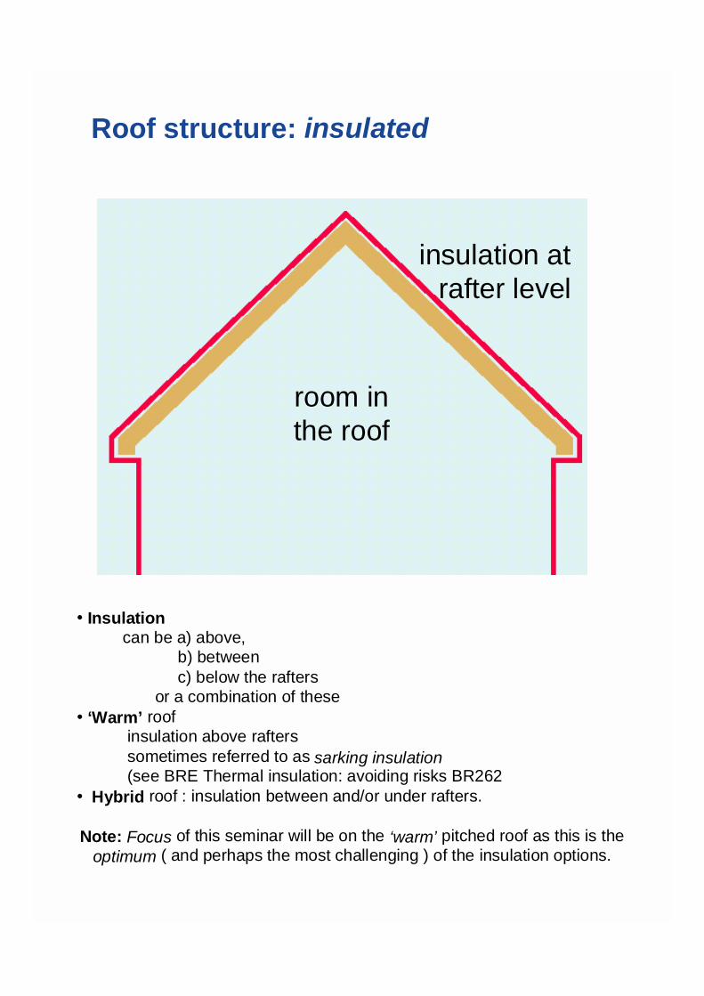
Roof structure: insulated
room inthe roof
insulation atrafter level
• Insulation can be a) above, b) between c) below the rafters or a combination of these• ‘Warm’ roof insulation above rafters sometimes referred to as sarking insulation (see BRE Thermal insulation: avoiding risks BR262• Hybrid roof : insulation between and/or under rafters.
Note: Focus of this seminar will be on the ‘warm’ pitched roof as this is theoptimum ( and perhaps the most challenging ) of the insulation options.

ADVANTAGES : INSULATED VSUNINSULATED ROOF STRUCTURE
• Increased living /working space for same “footprint”
• Additional space at lower cost
• Added value
• Allows room to grow
Cost of providing additional space in the attic can be less than 50% of the standard floor cost.
plus ----- with a ‘warm’ roof: - reduced risk of condensation on structural membranes. - thermal movement of roof structure reduced. - roof structure kept dry - no need for timber preservative treatment.

THE WARM PITCHED ROOF
Rafter
Tiling batten TilesCounterbatten
InsulationVapour permeableunderlay
- roof build up
• Insulation shown above and between rafters
• Vapour permeable underlay (breather type) can be laid either in direct contact with the insulation ( as shown ) or over the counterbattens
• Suitable for new build or where the roof covering is to be replaced ( note increase in roof height ! ) and where it would be difficult to provide eaves ventilation
Note: Need for a vapour control layer (VCL) ? YES for areas exposed to high humidity levels e.g swimming pools, kitchens, changing rooms. Use plasterboard (13 mm) to cover exposed XPS insulation.

THE WARM PITCHED ROOF CONCEPT
• rigid insulation over (and between) rafters
plus
• a water vapour permeable (breather) underlay
Note: Where proprietary products are to be specified,manufacturers’ recommendations should be followed.Designers should satisfy themselves that the performance ofthese products and the given recommendations have beenproven by relevant experience in use or by test data basedon the conditions and methods of application in equivalentand appropriate internal and external climatic conditions.

THE WARM PITCHED ROOF
• First …… thatched roofing !
• Developed from Scottish sarking - early 80’s
• Agrément certification - mid 80’s
• Thousands roofs, millions sq metres installed
• Includes all insulation types
• Minimal condensation problems
• No securement problems
Note: Thatched roof - really is a “breathing” warm roof
Sarking - originated in Germany / Scandinavia refers to a sheet or underskirt of boarding.
- traditionally in Scotland 25mm thick close timber boarding at underslating level. - helps reduce effect of wind uplift on slates.

Design considerations
! BS 5268 : Part 7 : 1990 Roofconstruction - rafters & purlins(Approved Document A : 1994 )
! BS 5534 : Part 1 : 1997 Slating & tiling! BS 6399 : Part 1 : 1984 Dead loading! BS 6399 : Part 2 : 1995 Wind loading! BS 6399 : Part 3 : 1988 Imposed &
snow loading
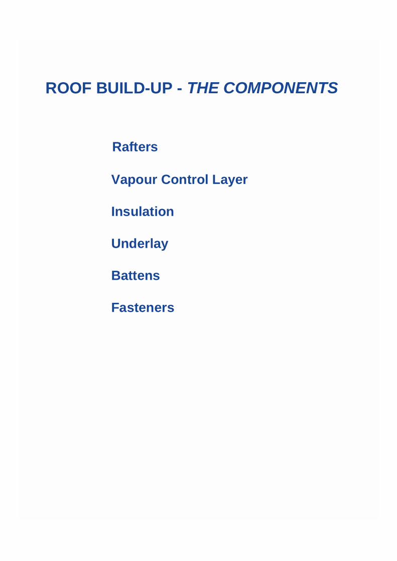
ROOF BUILD-UP - THE COMPONENTS
Rafters
Vapour Control Layer
Insulation
Underlay
Battens
Fasteners

RAFTERS
Consider:
• Roof slope
• Cut vs trussed
• Dimensions (and tolerances)
• Spacing
• Bracing
Note:
Must assume that insulation does not contribute tothe racking strength of roof structure.

VAPOUR CONTROL LAYER (VCL)
• Usually a membrane (eg 500 gauge polyethylene sheet)
• Substantially reduces transfer of water vapour
• Installed on warm side of insulation
A VCL reduces water vapour transfer through any building component inwhich it is incorporated.
(BRE document BR 262: ‘Thermal insulation - avoiding risks’ specifies aminimum water vapour resistance of 200 MNs/g. BS 5250 refers to the useof 500 gauge polyethylene with a range of 200 to 350 MNs/g, typically 250MNs/g.)
The VCL should be installed on the warm side of the insulation. ( Note that aVCL at ceiling level will require increased ventilation below it during the wettrade phases of construction.)
Performance of a VCL also is dependant on workmanship and build ability -see Clause 9.2 of BS 5250.
It is essential that it is adequately lapped and sealed so as to maintain itsintegrity.
Particular care should be given to detail design and installation aroundpenetrations through the VCL (e.g services, compartment walls) and to thesealing of punctures caused by fasteners.

INSULATION• Location - above / between / below (or any combination)
• Selection - thermal performance
- water vapour permeability - water resistance (absorption) - user friendliness
• Thickness
• Installation - thermal integrity - convection tight
Location:(a) over the rafters(b) between the rafters(c) under the raftersor any combination of theseNote : Option (a) is sometimes referred to as a “warm” roof construction or as“sarking” insulation.All options can be used for new roof constructions or where the roof is to bereplaced from rafter level up.Only options (b) and (c) can be used in situations where the roof covering cannot be removed or replaced.Selection:Rigid, semi-rigid and flexible insulants can be used. Each has its own specificphysical characteristics as regards performance and installation requirements -the manufacturers’ recommendations should be followed. cont ->

Thickness:The thickness of the insulation will be determined by the required thermalperformance as well as by the roof construction (see Approved DocumentL). It is important to ensure the continuity of the thermal insulation. If thisis broken eg by the rafters and /or penetrations through the roof, theresulting thermal bridges can increase the risk of localised condensationand pattern staining of ceilings at rafter line.
Note: Building Regulations require the effect of thermal bridging to betaken into account when calculating the thermal performance (U-value) ofthe roof. Refer to BS 5250 Section 9.6 and BRE Document 262: Thermalinsulation - avoiding risks.
Installation:Thermal integrity is essential.
The roof void should be completely insulated. For example gable endwalls will need to be insulated to their full height.
The designer should take care to ensure that there are no gaps or breaksin the insulation envelope.
The insulation should be installed to fit tightly at ridges, at eaves andaround penetrations. Seal if necessary with flexible (polyethylene) or PUfoam.
Insulation boards should fit tightly together with no gaps around them.Rigid board joints should be correctly positioned so as to shed any likelyincoming external water. Some types of board will require their joints tobe sealed with tape - refer to the manufacturers’ instructions.
Special care needs to be taken with rebated boards designed for over andbetween rafter installation e.g Roofmate PR to ensure that the rafterspacing is accurately set out so as to avoid gaps or unnecessary cutting ofboards.
Convection tight/airtight:A roof system in which the free movement of air through any section of theconstruction is prevented by use of airtight joints and seals is said to be“convection tight” or “airtight”.

INSULATION - typical physical properties
XPS EPS PUR MFThermal conductivity W/mK 0.025 0.036 0.024 0.036
Water vapour resistance(relative to MF)
- 140 60 80 1
Water vapour resistivity MNs/gm 1000 300 600 5
Water absorption % vol 0.3 6 3 ?
Compressive strength kPa 300+ 190max
175max
120max
Density kg/m3 30 15-30 30 180
• XPS - extruded foamed polystyrene EPS - expanded foamed polystyrene (bead board) PUR - polyurethane/polyisocyanurate MF - mineral fibre
• Thermal conductivityXPS, EPS measured at 90 days (after equilibrium reached) - long term value.PUR measured immediately after production ie before equilibriumreached - short term value.
• Water vapour resistanceDetermined relative to MF(air) for equivalent U-value thicknesses (XPS=50mm)
• Water absorption Be sure to take into account likely effect on thermal conductivity !

ROOFMATE* RL, PR- physical characteristics
PR RLDensity kg/m3 34 34Thermal conductivity W/mK 0.025 0.025Compressive strength kN/m2 300 300Water absorption % vol 0.3 0.3Water vapour resistivity MNs/gm 940 940
Board size mm 2500 x 600 2500 x 600Thickness mm 80, 90, 120 35, 50Edge profile - rebated tongue & groove
• Roofmate RL
Tongue and groove on all sides.Board should be laid so the tongues in horizontal joints face up the slope.
• Roofmate PR
Available with edge flanged to suit 38 and 50mm rafters - type 38 and 50respectively.Boards should be laid so that horizontal lap joints (i.e top and bottom of boards)point down the slope so that boards higher up the roof overlap those furtherdown (boards are marked so as to facilitate this e.g with an arrow pointing up theslope of the roof).
UNDERLAYS-REQUIREMENTS
- TRADITIONAL
• Keep water (snow, dust) out
• Air tight
• Adequate strength
- WATER VAPOUR PERMEABLE (Breather)
• As Traditional plus water vapour permeability
• Keep water etc. out - secondary defense against wind driven rain, snow and dust.
• Air tight - to reduce wind load on primary roof covering.
• Adequate strength - tensile, tear strength (for nails), extensibility (reduce movement under wind pressure). Working temp. range - 20 to + 80 deg C.
• Water vapour permeability
- Traditional underlay e.g BS747 Type IF felt These are defined (BS5250) as having a water vapour resistance in excess of 50MNs/g - Water vapour permeable (breather) underlay BS 4016 : 1995 Flexible building membranes (breather type) - max. water vapour resistance 0.6MNs/g BRE Thermal Insulation : Avoiding risks - specifies 0.1 - 2.0 MNs/g.

UNDERLAYSWATER VAPOUR RESISTANCE
Traditional MNs/gBS 747 Type IF felt 50 - 270Monarfil* 250 420
BreatherPermo* 0.20Tyvek* HD - Soft 0.24Tyvek* 2001 - Pro 0.16Roofshield* 0.08Monarperm* 450 0.11
InsulationXPS - 90mm 85PUR - 80mm 46MF - 115 mm 0.6 * Tradenames
• Monarfil 250 - reinforced polyethylene (0.25mm)
• Permo - laminated spunbond polypropylene
• Tyvek Soft - spunbond polyethylene (0.19mm)
• Tyvek Pro - spunbond polyethylene / polypropylene laminate (0.42mm)
• Roofshield - spunbond polypropylene laminate (0.60mm)
• Monarperm 450 - spunbond polypropylene (0.45mm)

BREATHER UNDERLAYS Performance criteria should reflect “real life” roof conditions
• Water vapour permeability + water resistance• - working conditions• - compatibility• - “tenting”• - “blinding”
• Installation
• Roof conditions : - 20 to +800C, 0 to 100% RH, seasonal, daily, hourly changes
• Compatibility - specifically with timber preservatives - water ( surfactants ) vs solvent based ( swelling ) cause loss of performance.
• “Tenting” - a problem with the early materials. Underlay leaks when touching surface below.
• “Blinding” - by dust, ice (?)
• Installation - laid direct on insulation (common practice in North) - can cause noise (ie wind flutter ) ?
or - supported on counterbattens(common practice in South) - userfriendliness => slipperiness underfoot for roofer !

BATTENS
● Tiling, counter
● Dimensions
● Location of underlay
● Securement
• When the insulation is installed over the rafters, counter-battens will be required to secure the insulation to the rafters and to provide drainage under the tile battens - refer to BS 5534 Part 1 Section 3.6.3.2.• Care should be taken to ensure that the construction techniques employed provide for adequate and accurate location of the fixings used to secure the battens and counterbattens to the rafters.• Width determined by diameter of fasteners (10 - 11 x diameter)• Thickness determined by method of securement• Underlay can be in direct contact with surface of insulation or located above the counter battens
• Who installs what ?
Carpenter - up to and including counterbattens (rafters, insulation)Roofer - above counterbattens (underlay, tile battens, tiles) or from the rafters up (insulation, battens, underlay,tiles)

SECUREMENT
- need to secure tiles/slates, underlay and insulation against dead wind and imposed loads
• Insulation consider: - thickness (over rafters), physical properties
• Fasteners
eg BS 1202 nails, Helifix Inskew, Proctor PR nails
consider: - penetration, pull-out strength, deflection under load - ease and accuracy of installation
Refer to manufacturers for advice
When the insulation is installed over the rafters the fasteners securing thecounter battens or battens through to the rafters must be of sufficient strengthand length and correctly spaced so as to resist dead, wind and imposedloads.
The following should be considered:
• Site locality - the assessment and determination of wind and imposed loads
• Roof Construction - roof pitch, rafter spacing, depth and width, insulationthickness; batten/counter batten length, width and depth; fastener diameter,length and spacing.
• Materials and related properties - slate/tile weight; rafter andbattens/.counter battens: timber specification; fasteners: pull-out and pull-through strengths, shear strength and deformation under load characteristics.
• Consideration should also be given to the deflection and possibleoverloading of the fasteners under load down the slope of the roof. It isrecommended that the deflection should not exceed 3mm. A fastener mustbe capable of withstanding the dead and imposed loads vectored down theslope of the roof i.e its maximum allowable bending stress must not beexceeded - refer to the fastener and insulation manufacturers for advice. Itmay be necessary to provide stronger and larger diameter fasteners (with acorresponding increase in batten and rafter dimensions) or a reducedspacing and/or stop battens (i.e parallel to the eaves/ridge)
Note : The trend towards increased thickness of insulation with reduced
U values (June 2000 proposals to change Approved Document L).
SECUREMENT cont

Securement cont
! BS 6399 : Part 1 : 1996 Deadloads! BS 6399 : Part 2 : 1995 Wind uplift! BS 6399 : Part 3 : 1988 Imposed Loads! BS 5268 : Part 2 : 1996! BS 5534 : Part 1 : 1997! BS 1202 : Part 1 : 1994
use above to determine fastener sizeand density ( per m2)
Note:Designers must take into account the two loading conditions forthe fasteners:• Wind uplift on the roof.• Resistance to slip (deflection of the fastener) down the slope - dependant on the pitch of the roof and the dead and imposed loading. Insulation should not be considered to be a structural material.
Refer to manufacturer’s literature for the specialist fasteners.

Fasteners - method of securement
Tile battensnailed to counter battens
Counter battens nailed torafters through insulation
Rafter thickness
• Figure above shows a method of securement for insulation laid over and between the rafters, in this case Roofmate PR.
• Counterbattens 32 mm thick secured with galvanised slab nails 100mm long x 3.35 mm dia spaced at 200 and 150 mm centres for duo and mono pitched roofs respectively - refer to BS 5268 : Part 2 : 1996.
• Tiling battens are secured with galvanised slab nails at the required gauge - refer to BS 5534 : Part 1: 1997.
Tiles

BUILDING REGULATIONS
“Reasonable provision shall be madefor the conservation of fuel and powerin buildings by limiting the heat lossthrough the fabric of the building”
• Building Regulations 1991, amended 1994
- Requirement LI : Conservation of Fuel and Power

BUILDING REGULATIONS
Approved Document L : 1995 U-values
Approved Document L
Maximum U-values (W/m2K)
DWELLINGS
SAP </= 60 >60 Cold roof 0.20 0.25 Warm roof 0.20 0.35
OTHER BUILDINGS
Cold roof 0.25 Warm roof - residential 0.35 - others 0.45
• If roof slope is greater than 70o then max U = 0.45 W/m2K
• For building classification see Approved Document B
• Building Regulations specify maximum allowable U-values - the optimum cost effective U-values are in fact lower eg:
W/m2K Floors 0.35
Roofs 0.20 - 0.25Walls 0.30 - 0.35

BUILDING REGULATIONS CONDENSATION Approved Document F:1995
“Adequate provision shall be made to prevent excessive condensation in a roof”
but …. Is based on traditional underlay experience
therefore …..
refer to: BRE Thermal insulation : avoiding risks 1994 - see Section 2.7 - 2.10 ‘Sarking insulation’
BS 5250 1989 -see Clauses 9.1, 9.2 and 9.3

CONDENSATION - it’s prevention
• Short, long term concerns
• Insulation - continuity, convection tight, performance
• Underlay - choice, performance
• Roof covering (tiles/slates) - air permeability (?)
• Ventilation
YES - between underlay/roof covering
YES - between insulation/traditional underlay
NO - between insulation/breather underlay
Control of condensation is of particular concern for those roofsystems where a breather underlay is used without a ventilatedairspace between it and the insulation. It is recommended that acondensation risk analysis is undertaken - refer to to BS 5250.Use of the criteria for condensation build-up within the roof systemas detailed in BS 6229 : 1982 (Section A.2.5.5.) is recommended.
The roof system below a breather underlay should be designedand installed so as to be convection tight as is possible throughoutits design life.
Consideration should be given to installing a VCL on the warmside of insulation if the insulation has a low water vapourresistance - refer to the insulation manufacturer for advice.
cont ->

For buildings with high internal temperatures and humidities it isrecommended that a VCL be installed and for exceptional conditions,as may be experienced in say swimming pools, laundries, that theadvice of a design specialist be sought.
Ventilation
- defined as “ the controlled movement of air”
There are two air spaces to be considered:
Between the underlay and the insulation
For traditional underlays ventilation should be provided inaccordance with the recommendations given in BS 5250 andApproved Document F2 (1990). For breather underlays ventilation isnot normally required.
Between the roof covering and underlayWhere a traditional underlay is used it is not normally necessary toprovide ventilation.
Where a breather underlay is used without ventilation between theunderlay and insulation it will be necessary to ensure that there isadequate ventilation. This may be provided through the slate/tileassembly. Apertures for ventilation can be provided at the eaves,ridge or incorporated into the slate/tile assembly - refer to BS 5250 forventilation aperture sizes.
NOTE: Ventilation through the slate/tile joints may not be sufficientdue to the close fitting of the slates/tiles. There may also be a riskthat the joints become blocked by vegetation or dust over the lifespanof the roof. Additional ventilation inlets or outlets may, therefore, berequired. Particular attention should be given to long span roofs toensure that adequate ventilation is provided.

BUILDING REGULATIONS
FIRE
APPROVED DOCUMENT B : 1992
EXTERNAL FIRE SPREAD - B4 BS 476 : Part 3 : 1958
AA (best) rating - tile/slate roofs - unaffected by insulation
INTERNAL FIRE SPREAD - B2
BS476 : Part 7 : 1971
Class O rating - 13mm plasterboard
• BS476 : Part 7 External fire exposure roof tests• BS476 : Part 1 Surface spread of flame test
- lists Classes 1 (highest) to 4; XPS is unclassifiable Class O is not identified in BS476. However, it can be achieved by materials of limited combustibility e.g plasterboard or a Class 1 material which has a fire propagation index (I) < 12 and a sub-index (I,) < 6.
• For useful information on aspects of XPS in building applications see BS 6203 : 1989

INSULATED PITCHED ROOFING
In summary:
• Warm roof concept 15 + years proven track record minimal condensation problems secure• Design for the total system• Pay attention to the design of details*• Take care in installation
The issues:
• Insulation - location, selection, installation
• Underlay - selection, performance, installation
• Condensation - its prevention
• Securement
* see end of tutorial for typical details

Case Case study - Hospital - Hospital
Extension - 2600m2 insulated pitched roof
• Architects: Watkins, Gray International
• Main contractor: J Longley & Co.
• Insulation installer: NH Etheridge Ltd
• Roofer: Cobsen, Davies
• Location: Conquest Hospital, Hastings, East Sussex• Project: BUPA extension - completed 1998

Case study - Hospital
! Insulation: Roofmate* PR Type 50 (90mm)! Roof space for services - heating, ventilation

Case study - Hospital
! Underlayer:: TyvekTyvek 2001-B Pro 2001-B Pro
(over (over counterbattenscounterbattens))
!! SecurementSecurement:: Helifix InscrewHelifix Inscrew 600 600fasteners - 110mm longfasteners - 110mm long
!! Tiles:Tiles: MarleyMarley Modern Modern

Case study - HospitalU-value calculations
Tiles
Tyvek 2001-B Pro
Roofmate PR
U-value = 0.25 W/m2K
Vented airspace
Unvented airspace
Plasterboard
Thickness Thermal Resistance (mm) (m2K/W)Outside surface resistance - 0.020Concrete tiles 8.00 0.007Vented airspace - 0.120(between tiles and sarking)Tyvek 2001-BPro - -Unvented airspace - 0.180Roofmate PR 90.00 3.600Unvented airspace - 0.180Plasterboard 13.00 0.081Inside surface resistance - 0.100

•Notes:•Element: Pitched roof, ceiling at rafter line, warm pitched roof•Exposure: exposed•Internal surface emissivity: high•External surface emissivity: high•Building use: hospital•Environmental conditions Summer Winter•Internal temp ºC 25 25•External temp ºC 18 5•Internal humidity % 60 60•External humidity % 65 95
•Construction Thickness (mm) Vapour Resistance (MNs/g)•Outside surface resistance - -•Concrete tiles 8.00 0.91•Vented airspace - -•(between tiles and sarking)•Tyvek 2001-BPro - 0.16•Unvented airspace - -•Roofmate PR 30.00 28.08•Roofmate PR 60.00 56.16•Umvented airspace - -•Plasterboard 13.00 0.68•Inside surface resistance - -
-10 0 10 20 30Red : Actual temperature profile
Blue : dew point temperature
Condensation occurs where red and blue lines touch or cross
Case study - HospitalCondensation riskanalysis
U-value: 0.25 W/m2K
Condensation build upwinter 0 g/m2
summer 0 g/m2
annual 0 g/m2
Temperature ºC

Warm pitched roof construction - detailing
7
6
5
4
3
2
1

Warm pitched roof construction
Rafter
Tiling battens TilesCounter battens
Vapour permeablemembrane
Type A - insulation over and between rafters - Roofmate PR
Roofmate PR Insulation

A1- Eaves detail
Ensure continuityof insulation
Set rebated edges of insulationover rafters
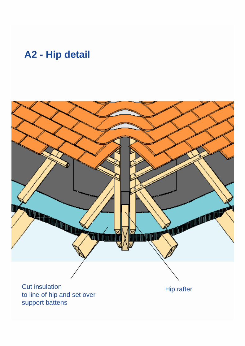
A2 - Hip detail
Cut insulationto line of hip and set oversupport battens
Hip rafter

A3 - Roof window detail
Cut insulation to fit tight against roofwindow trimmers and seal with gap fillerRoof window
Counter batten

A4 - Valley detail
Cut insulation boards toline of valley. Form rebateto set over valley boards
Discontinuous edge batten toallow drainage and ventilation
Gutter lining onseparating layer
Set valley boardsbetween rafters

A5 - Ridge detail
Cut insulation to fittight at ridge and sealwith gap filler
Nail counterbattens to rafters
Nail tiles tobattens
Nail tiling battensto counterbattens

A6 - Abutment detail
Fix batten ingap between insulationand wall
UnderlayInsulation over andbetween rafters

A7 - Verge detail
Insulation set over andbetween rafters BargeboardFlying rafter

Warm pitched roof constructionType B - insulation over rafters Roofmate RL
Tiling battensCounterbattens
Vapourpermeablemembrane
Tiles
RafterRoofmate RLInsulation

B1 - Eaves detail
Ensure continuityof insulation

B2 - Hip detail
Cut insulationto line of hip and set ontosupport battens Hip rafter
Supportbattens

B3 - Roof window detail
Cut insulation to fit tight againstroof window trimmers and sealwith gap fillerRoof window
Counter batten

B4 - Valley detail
Cut insulationboards to line ofvalley and set overvalley boards
Discontinuous edgebatten to allowdrainage andventilation
Gutter lining onseparating layer
Set valley boardsbetween rafters
Valley rafter

B5 - Ridge detail
Cut insulation to fit tight at ridgeand seal with gap filler
Nail counterbattens to rafters Nail tiles to battens
Nail tiling battens tocounterbattens

B6 - Abutment detail
Plasterboardceiling
Nail battens to counterbattens
Lay insulation boardsover rafters
Nail counterbattens to rafters

B7 - Verge detail
Plasterboard ceiling Bargeboard
Make up piece of insulation setover gable wall

INSULATED PITCHED ROOFING
Summarising :
• Warm Roof: 15 years proven experience ! minimal condensation, securement problems• Design for total system• Attention to detail design• Care in installation
Issues :• Insulation selection, performance,
installation• Underlay selection, performance, installation• Condensation: it’s prevention
• Securement

If the following questionnaire is successfully completed and sent to Dow ConstructionProducts, 2 Heathrow Boulevard, 284 Bath Road, West Drayton, Middx UB7 0DQFax Number 0208 917 5413 a CPD certificate will be forwarded to you.
1. In the “warm roof concept” the insulation is placed
above the rafters
between the rafters
above and between the rafters
between the rafters
2. If a pitched roof is insulated at rafter level (and the loft space is to be utilised)
What are the maximum allowable U-values
0.25 0.35 0.45
Domestic Buildings (SAP>60)
Non-Domestic
- Old Peoples Home
- Office
3. What is the difference between a “traditional” and “breather” underlay
Water tight
Air tight
Tear Strength (nails)
Tensile properties
Water Vapour permeable
4. Where would you provide ventilation in a pitched roof construction insulated at rafter
level if a) a traditional or b) a breather underlay is used ?
(a) (b)
Below rafters
Below insulation
Between insulation and underlay
Between underlay and tiles/slates

5. Which properties are of particular importance for breather underlays ?
Water resistance
Water vapour resistance
Compatibility with timber preservatives
Tear strength
Tearing resistance
Slipperiness
Blinding resistance
Colour
Air tightness
6. In designing a pitched roof which standards should you refer to for
1 2 3 4 5
General design - slating/tiling
Wind loads
Design - timber structure
Dead loads
Imposed loads
1 = BS 6399 : Part 1
2 = BS 6399 : Part 2
3 = BS 6399 : Part 3
4 = BS 5534 : Part 1
5 = BS 5268 : Part 2

7. Where would you go for advice on how to avoid condensation in a pitched roof ?
BS 5250
Approved Document L
Approved Document F
BRE 262 Thermal Insulation : avoiding risks
BS 5534
Insulation manufacturers
8. In a “warm roof construction” what issues did you need to consider to avoid/reducethe risk of condensation. ?
Use of a vapour control layer
Water vapour permeability of insulation
Convection tightness of insulation layer
Type of underlay
Location of underlay
Where to ventilate
Air permeability of primary roof covering
Drying our of building structure
Attention to details e.g. at eaves
Securement of underlay
9. What factors must be considered when selecting and specifying fasteners ?
Length
Diameter
Pull-out strength (from timber)
Bending stress
Ease and accuracy of installation
Deflection under load
Width of battens, rafters

10. Which of these should be considered when selection of insulation for
installation or rafter level ?
Location
Compressive strength
Rigidity
Water vapour permeability
Water resistance
Thermal conductivity
Ease of installation
Fire resistance
Nail ability
Name _______________________________________
Company Name______________________________________________________
Address______________________________________________________
______________________________________________________
______________________________________________________
Telephone Number______________________________________________________