
Douglas Getson PE, Global Product Manager, ZA … · ... Enerdata & Economist Intelligence Unit....
37
G R T f ™ Douglas Getson PE, Global Product Manager, ZA Transformer Day, May 2013 Green-R-Trafo™ Green transformer program Green transformer program © ABB Group May 20, 2013 | Slide 1
Transcript of Douglas Getson PE, Global Product Manager, ZA … · ... Enerdata & Economist Intelligence Unit....

G R T f ™Douglas Getson PE, Global Product Manager, ZA Transformer Day, May 2013
Green-R-Trafo™Green transformer programGreen transformer program
© ABB Group May 20, 2013 | Slide 1

Agenda
Energy Policy
Transformer Losses and Efficiencyy
AMDT - Amorphous Metal Distribution Transformers
BIOTEMP® - Natural Ester Dielectric Fluid
Green-R-Trafo™ - Green Transformer Program
Summaryy
© ABB Group May 20, 2013 | Slide 2
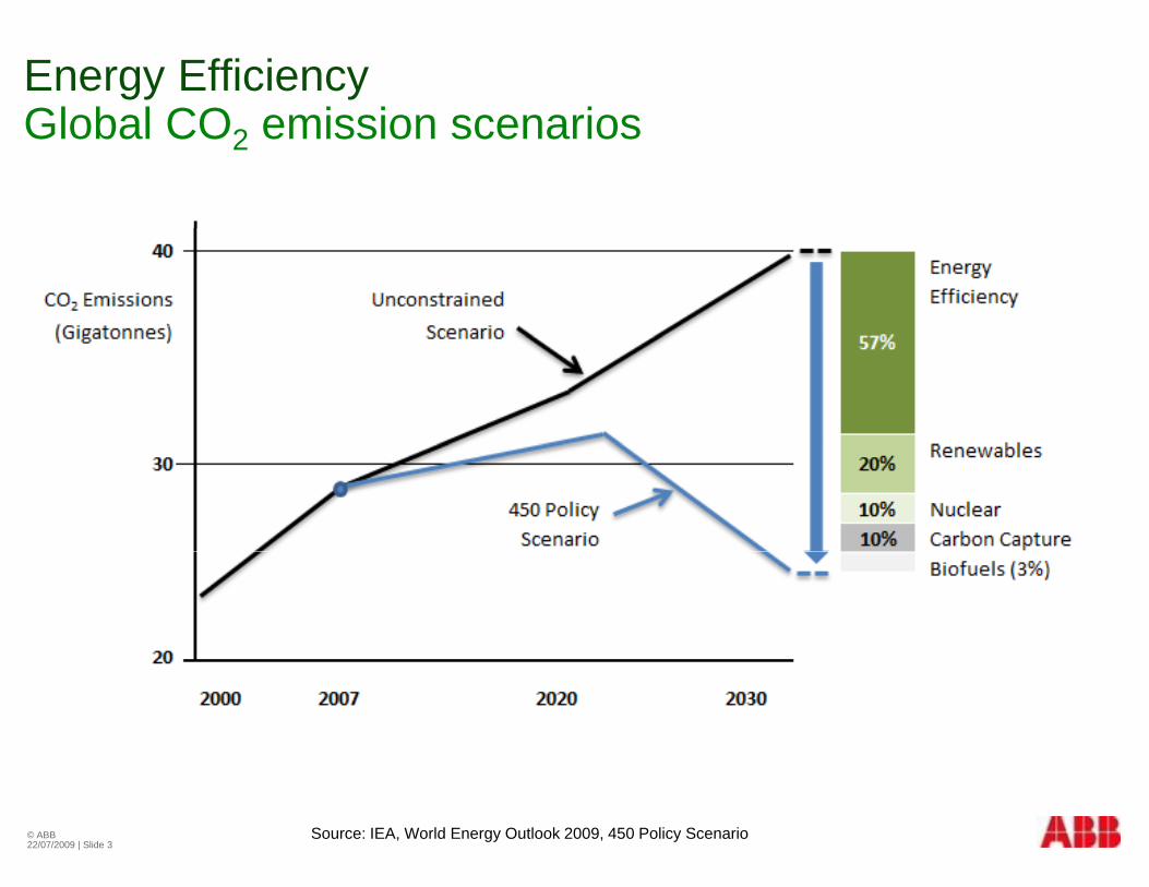
Energy Efficiency Global CO emission scenariosGlobal CO2 emission scenarios
© ABB22/07/2009 | Slide 3
Source: IEA, World Energy Outlook 2009, 450 Policy Scenario
South AfricaHistorical grid losses and emissionsHistorical grid losses and emissions
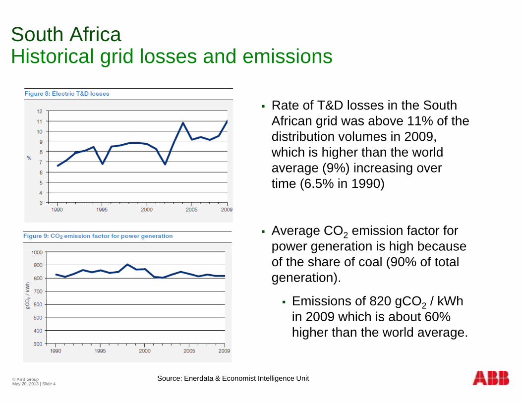
Rate of T&D losses in the South Rate of T&D losses in the South African grid was above 11% of the distribution volumes in 2009, which is higher than the worldwhich is higher than the world average (9%) increasing over time (6.5% in 1990)
Average CO2 emission factor for power generation is high because po e ge e at o s g becauseof the share of coal (90% of total generation).
Emissions of 820 gCO / kWh Emissions of 820 gCO2 / kWh in 2009 which is about 60% higher than the world average.
© ABB Group May 20, 2013 | Slide 4
Source: Enerdata & Economist Intelligence Unit
South AfricaEnergy consumption and policyEnergy consumption and policy
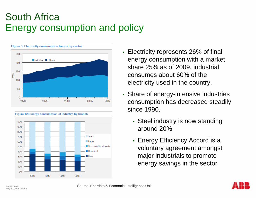
Electricity represents 26% of final Electricity represents 26% of final energy consumption with a market share 25% as of 2009. industrial consumes about 60% of theconsumes about 60% of the electricity used in the country.
Share of energy-intensive industries consumption has decreased steadily since 1990.
Steel industry is now standing Stee dust y s o sta d garound 20%
Energy Efficiency Accord is a voluntary agreement amongstvoluntary agreement amongst major industrials to promote energy savings in the sector
© ABB Group May 20, 2013 | Slide 5
Source: Enerdata & Economist Intelligence Unit
Transformer EfficiencyGlobal standardsGlobal standards
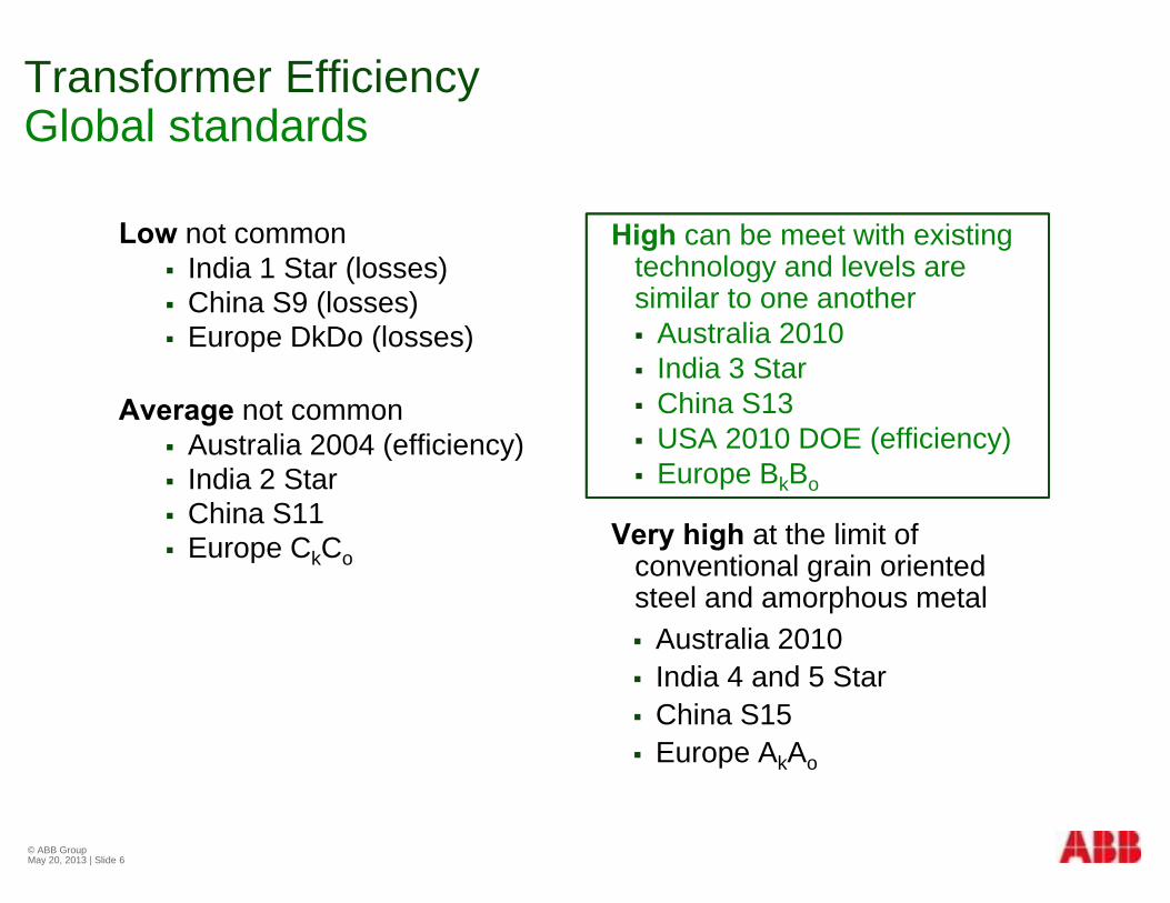
High can be meet with existingLow not common High can be meet with existing technology and levels are similar to one another Australia 2010
Low not common India 1 Star (losses) China S9 (losses) Europe DkDo (losses) Australia 2010
India 3 Star China S13 USA 2010 DOE (efficiency)
Europe DkDo (losses)
Average not common Australia 2004 (efficiency) ( y)
Europe BkBo
Very high at the limit of conventional grain oriented
Australia 2004 (efficiency) India 2 Star China S11 Europe CkCo conventional grain oriented
steel and amorphous metal Australia 2010
India 4 and 5 Star
p k o
India 4 and 5 Star China S15 Europe AkAo
© ABB Group May 20, 2013 | Slide 6
Transformera s o eLosses and efficiencyy
© ABB Group May 20, 2013 | Slide 7
Distribution TransformersNo load losses have greater impact at lower loadsNo-load losses have greater impact at lower loads
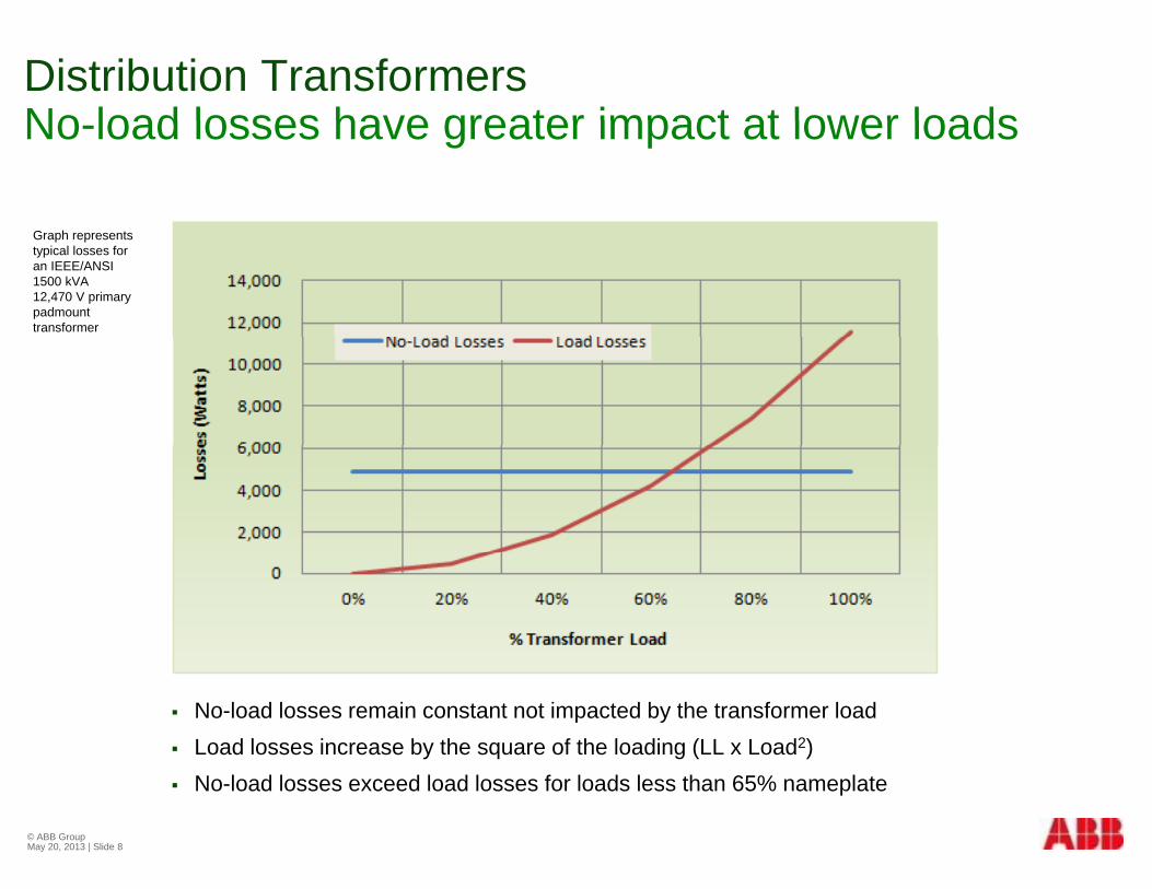
Graph represents typical losses for an IEEE/ANSI 1500 kVA 12,470 V primary padmount transformer
No-load losses remain constant not impacted by the transformer load Load losses increase by the square of the loading (LL x Load2)
© ABB Group May 20, 2013 | Slide 8
No-load losses exceed load losses for loads less than 65% nameplate

Energy EfficiencyTransformer losses impact energy efficiencyTransformer losses impact energy efficiency
Distribution transformers are already efficient (~98%) but due to the Distribution transformers are already efficient (~98%) but due to the large installed based equates to a significant amount of losses
10)(%5PFkVALEfficiency
Efficiency reduced by N-Load (NL) and Load (LL) losses
Hysterisisbeing the reorientation of the magnetic moments taking
)()10()(% 23 LLLNLPFkVAL
Efficiency
y y ( ) ( )
NL losses are from the core when transformer is energized Hysteresis Losses - chemistry, coating, processing
place 50 or 60 times per second.
Eddy Currentsflow perpendicular to
Eddy Current Losses – laminate thickness
LL losses are from the windings when there is load on the transformer and is proportional to the load (amps)
the flux but broken up by laminating the core and adding silicon increasing resistivity
I2R Loss - material (CU vs. AL), size and length Eddy Loss - geometry, proximity to steel parts
© ABB Group May 20, 2013 | Slide 9
L = per unit load, kVA = nameplate rating, PF = power factor, NL = No Load losses, LL = Load Losses
Transformer DesignOptimising for optimal lossesOptimising for optimal losses
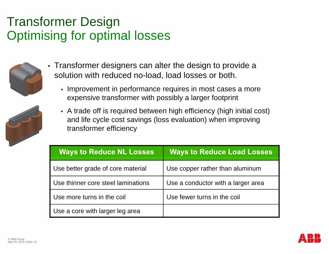
Transformer designers can alter the design to provide a Transformer designers can alter the design to provide a solution with reduced no-load, load losses or both. Improvement in performance requires in most cases a more
e pensi e transformer ith possibl a larger footprintexpensive transformer with possibly a larger footprint
A trade off is required between high efficiency (high initial cost) and life cycle cost savings (loss evaluation) when improving transformer efficiency
Ways to Reduce NL Losses Ways to Reduce Load Losses
transformer efficiency
Use better grade of core material Use copper rather than aluminum
Use thinner core steel laminations Use a conductor with a larger area
Use more turns in the coil Use fewer turns in the coil
Use a core with larger leg area
© ABB Group May 20, 2013 | Slide 10
Amorphous Metalo p ous etaLower no-load losses
© ABB Group May 20, 2013 | Slide 11
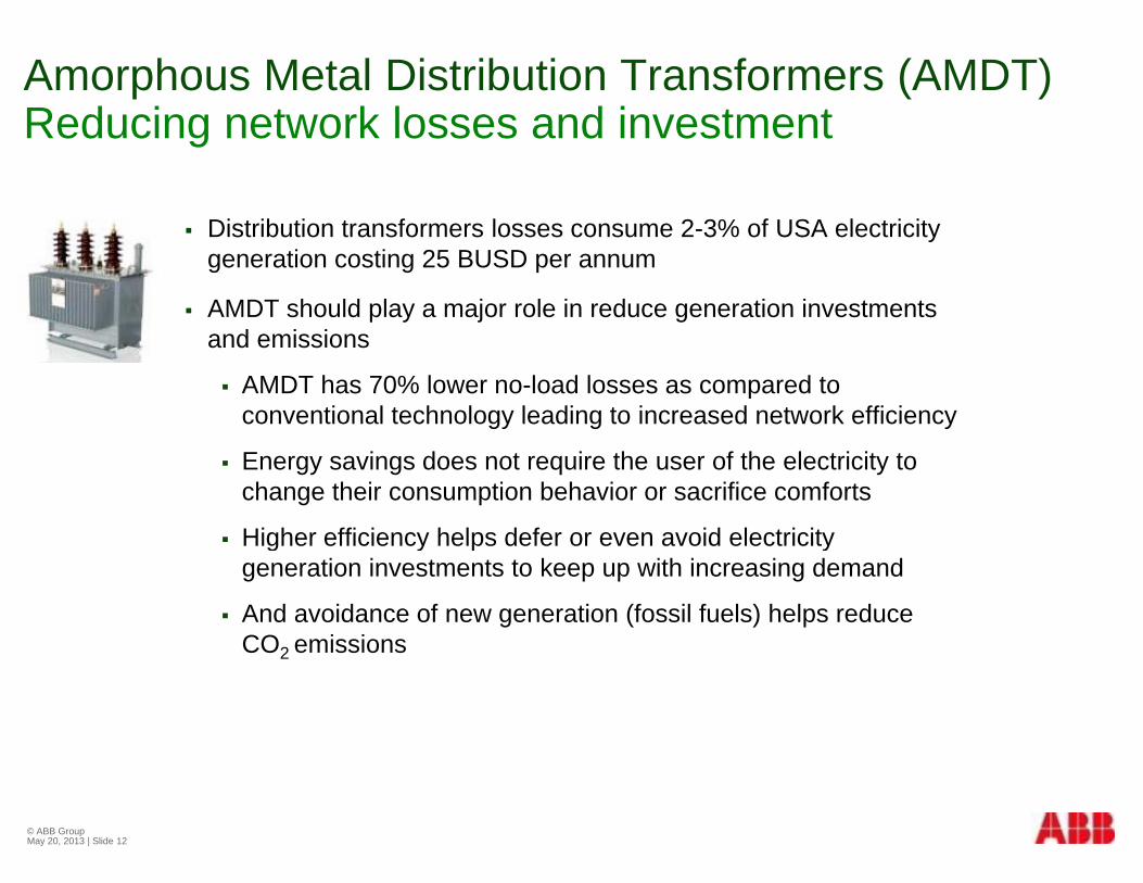
Amorphous Metal Distribution Transformers (AMDT)Reducing network losses and investmentReducing network losses and investment
Distribution transformers losses consume 2 3% of USA electricity Distribution transformers losses consume 2-3% of USA electricity generation costing 25 BUSD per annum
AMDT should play a major role in reduce generation investments and emissionsand emissions
AMDT has 70% lower no-load losses as compared to conventional technology leading to increased network efficiency
Energy savings does not require the user of the electricity to change their consumption behavior or sacrifice comforts
Higher efficiency helps defer or even avoid electricity g y p ygeneration investments to keep up with increasing demand
And avoidance of new generation (fossil fuels) helps reduce CO2 emissions2
© ABB Group May 20, 2013 | Slide 12
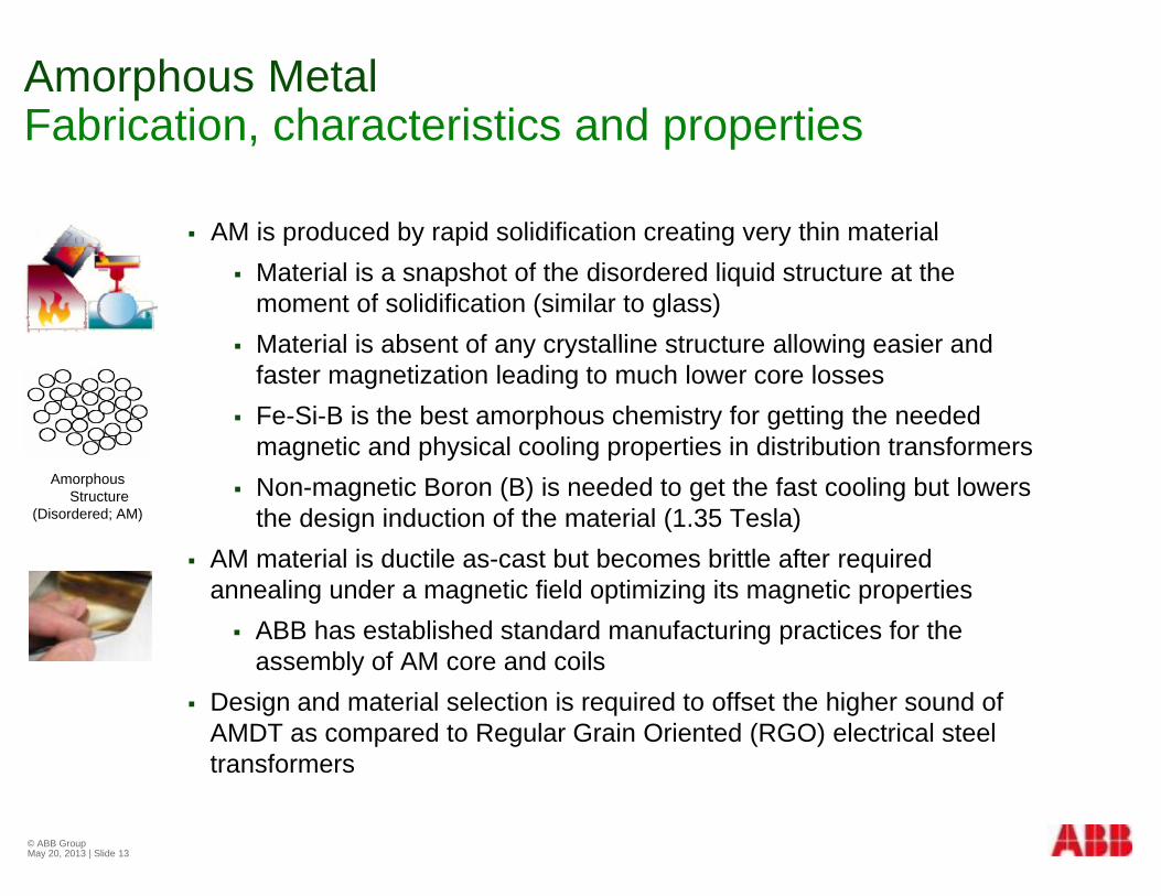
Amorphous MetalFabrication characteristics and propertiesFabrication, characteristics and properties
AM is produced by rapid solidification creating very thin material AM is produced by rapid solidification creating very thin material Material is a snapshot of the disordered liquid structure at the
moment of solidification (similar to glass)Material is absent of any crystalline structure allowing easier and Material is absent of any crystalline structure allowing easier and faster magnetization leading to much lower core losses
Fe-Si-B is the best amorphous chemistry for getting the needed magnetic and physical cooling properties in distribution transformersmagnetic and physical cooling properties in distribution transformers
Non-magnetic Boron (B) is needed to get the fast cooling but lowers the design induction of the material (1.35 Tesla)
AM material is ductile as cast but becomes brittle after required
Amorphous Structure
(Disordered; AM)
AM material is ductile as-cast but becomes brittle after required annealing under a magnetic field optimizing its magnetic properties ABB has established standard manufacturing practices for the
assembly of AM core and coilsassembly of AM core and coils Design and material selection is required to offset the higher sound of
AMDT as compared to Regular Grain Oriented (RGO) electrical steel transformers
© ABB Group May 20, 2013 | Slide 13

Transformer Core LossesLoss componentsLoss components
Core losses are the power consumed in magnetizing core material Core losses are the power consumed in magnetizing core material through its excitation cycle
Core losses are the sum of the following loss componentsH t i l L B1 7 f
B (T)
Hysteresis losses Lh B1.7 x f Eddy Classical losses Lcl (B x f)2 x t2 / Eddy Excess losses Lex (B x f)1.5 x (d x t) /
H (A/M)
B-H Curve
Hysteresis is the ease of magnetization and depends linearly on excitation frequency – area within the B-H curve
Eddy currents make up the rest of the losses generated by variation in
VariablesB = flux densityf = frequencyt = thicknessresistivityd = domain width
Material is Eddy currents make up the rest of the losses generated by variation in the magnetic properties of the material
Classical are found within the uniform structure of the material dependent on material thickness and resistivity
Material is organized into domains, or regions wherein all magnetic moments are lined up in one direction dependent on material thickness and resistivity
Excess are the currents localized within the domain walls of the material dependent on material thickness, resistivity and domain spacing
direction
Domain walls are the boundaries between the domains
spacing
© ABB Group May 20, 2013 | Slide 14

Transformer Core LossesAM losses are inherently lowerAM losses are inherently lower
RGO Electrical Steel (Fe Si)RGO Electrical Steel (Fe-Si)
RGO losses have been reduced over the years by improving grain orientation (Lh), reducing thickness (Lcl , Lex), and scribing to reduce domain spacing (Lex)
Lh, Lcl, Lex losses are approximately 40%, 35%, and 25%
Amorphous Metal (Fe-Si-B)
AM is inherently thin and, due to a lack of crystalline structure, has y , y ,high resistivity and an ease of magnetization
Thus, hysteresis (Lh) and eddy current losses (Lcl , Lex) are naturally lower in AM than in RGOnaturally lower in AM than in RGO
Lh and Lex are each 50% but Lcl is negligible
© ABB Group May 20, 2013 | Slide 15
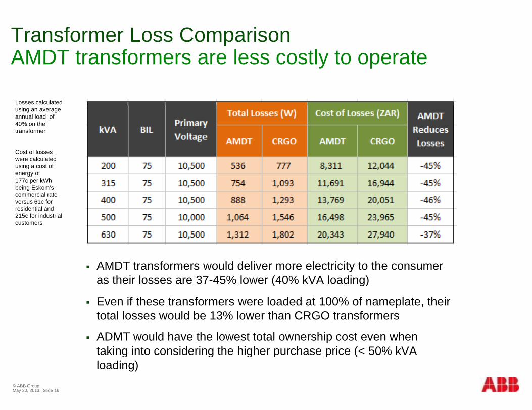
Transformer Loss ComparisonAMDT transformers are less costly to operateAMDT transformers are less costly to operate
Losses calculated using an average annual load of 40% on the transformer
Cost of losses were calculated using a cost of energy of 177c per kWh being Eskom’s commercial rate versus 61c for residential and 215c for industrial customers
AMDT transformers would deliver more electricity to the consumer as their losses are 37-45% lower (40% kVA loading)
Even if these transformers were loaded at 100% of nameplate, theirEven if these transformers were loaded at 100% of nameplate, their total losses would be 13% lower than CRGO transformers
ADMT would have the lowest total ownership cost even when taking into considering the higher purchase price (< 50% kVAtaking into considering the higher purchase price ( 50% kVA loading)
© ABB Group May 20, 2013 | Slide 16
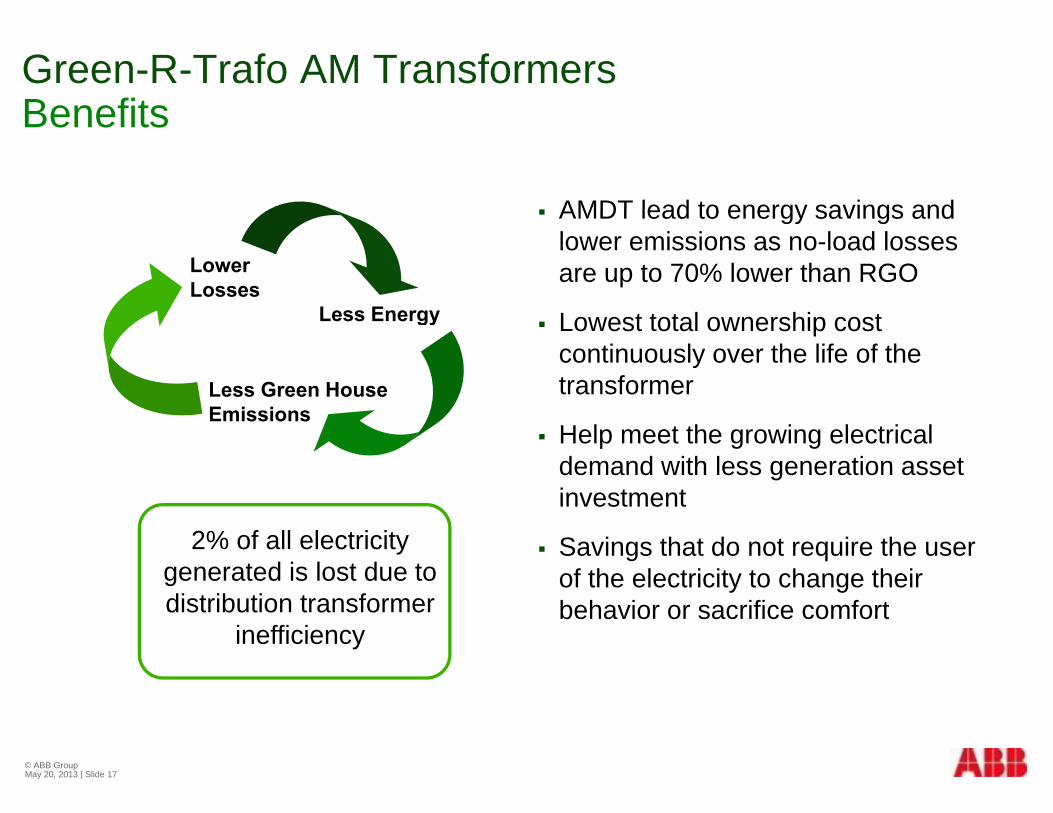
Green-R-Trafo AM Transformers BenefitsBenefits
AMDT lead to energy savings and AMDT lead to energy savings and lower emissions as no-load losses are up to 70% lower than RGOLower
LossesL E Lowest total ownership cost
continuously over the life of the transformer
Less Energy
Less Green House E i i
Help meet the growing electrical demand with less generation asset investment
Emissions
investment
Savings that do not require the user of the electricity to change their b h i ifi f t
2% of all electricity generated is lost due to distribution transformer behavior or sacrifice comfortdistribution transformer
inefficiency
© ABB Group May 20, 2013 | Slide 17
BIOTEMP®ODielectric fluid
© ABB Group May 20, 2013 | Slide 18

Ester Dielectric FluidsDevelopment of an alternative fluidDevelopment of an alternative fluid
Ester fluids came to market in the 1980’s as an alternative with Ester fluids came to market in the 1980 s as an alternative with fire safety and biodegradability properties
Esters are a class of organic compounds that can be chemically synthesized (synthetic esters) or from agricultural products (natural esters)
Natural esters have a near neutral carbon footprint as seed oilNatural esters have a near neutral carbon footprint as seed oil production nets a negative CO2 footprint (photosynthesis)
Natural ester composition from 100% renewable resource
Natural esters are recognized as environmentally friendly and “less flammable” dielectric insulating fluid by the industry
Natural esters are readily biodegradable in 21 days and non Natural esters are readily biodegradable in 21-days and non toxic
© ABB Group May 20, 2013 | Slide 19
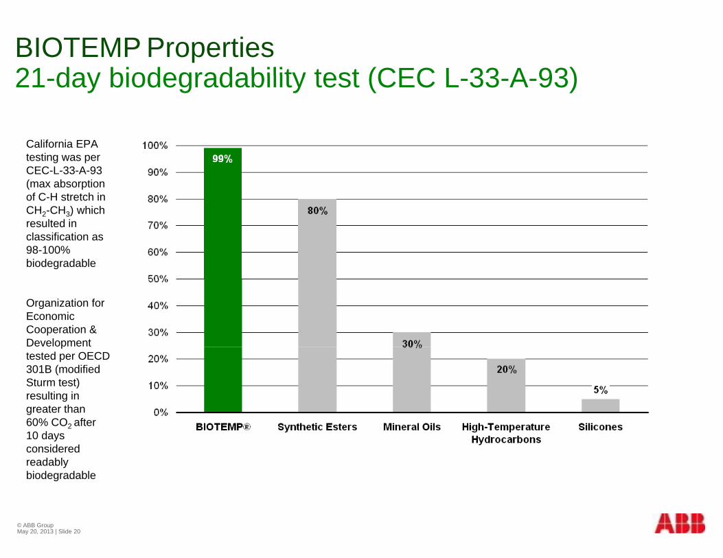
BIOTEMP Properties21 day biodegradability test (CEC L 33 A 93)21-day biodegradability test (CEC L-33-A-93)
California EPACalifornia EPA testing was per CEC-L-33-A-93 (max absorption of C-H stretch in CH2-CH3) whichCH2-CH3) which resulted in classification as 98-100% biodegradable
Organization for Economic Cooperation & Development ptested per OECD 301B (modified Sturm test) resulting in greater than g60% CO2 after 10 days considered readably biodegradable
© ABB Group May 20, 2013 | Slide 20
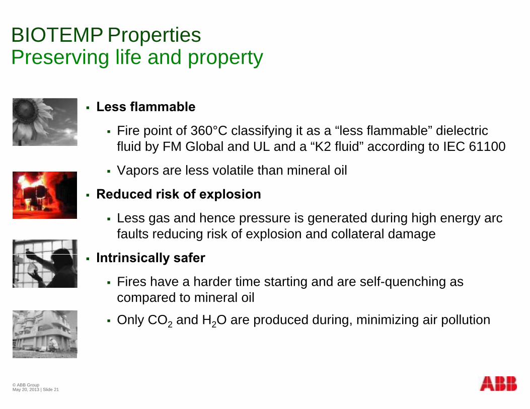
BIOTEMP PropertiesPreserving life and propertyPreserving life and property
Less flammable Less flammable
Fire point of 360°C classifying it as a “less flammable” dielectric fluid by FM Global and UL and a “K2 fluid” according to IEC 61100
Vapors are less volatile than mineral oil
Reduced risk of explosion
Less gas and hence pressure is generated during high energy arc faults reducing risk of explosion and collateral damage
I t i i ll f Intrinsically safer
Fires have a harder time starting and are self-quenching as compared to mineral oilp
Only CO2 and H2O are produced during, minimizing air pollution
© ABB Group May 20, 2013 | Slide 21
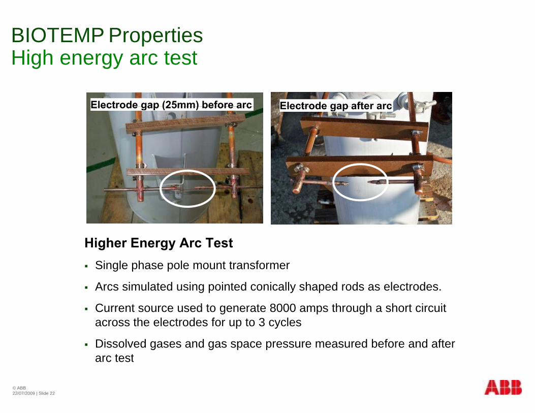
BIOTEMP PropertiesHigh energy arc testHigh energy arc test
Electrode gap (25mm) before arc Electrode gap after arcElectrode gap (25mm) before arc Electrode gap after arc
Higher Energy Arc Test Single phase pole mount transformer
Arcs simulated using pointed conically shaped rods as electrodes.
Current source used to generate 8000 amps through a short circuit Current source used to generate 8000 amps through a short circuit across the electrodes for up to 3 cycles
Dissolved gases and gas space pressure measured before and afterarc test
© ABB22/07/2009 | Slide 22
arc test

High Energy Arc TestMineral oil filled transformerMineral oil filled transformer
Pole mount single phase transformer filled with mineral oil
At the point of highest energy level, internal pressures generated by the arc ruptures the cover with an ensuing fire as the hot oil is
© ABB22/07/2009 | Slide 23
y p gexposed to the atmosphere.
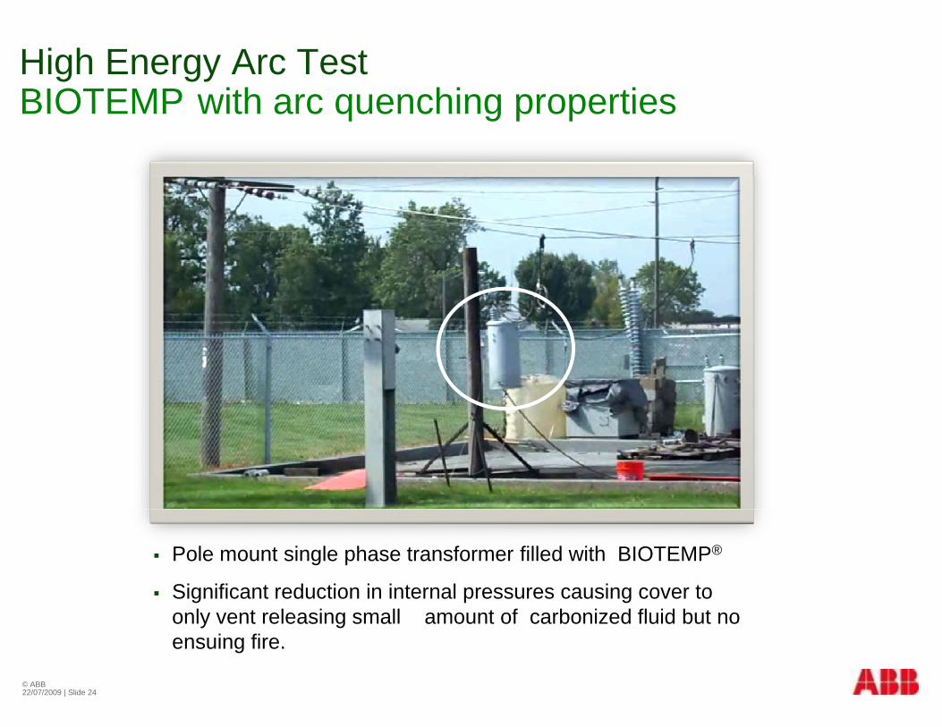
High Energy Arc TestBIOTEMP with arc quenching propertiesBIOTEMP with arc quenching properties
Pole mount single phase transformer filled with BIOTEMP®
Significant reduction in internal pressures causing cover to only vent releasing small amount of carbonized fluid but no
© ABB22/07/2009 | Slide 24
ensuing fire.

BIOTEMP PropertiesEnhancing performanceEnhancing performance
Greater affinity for water Greater affinity for water
Higher water saturation limit than mineral oil 4 times that of mineral oil under normal operating conditions 4 times that of mineral oil under normal operating conditions
BIOTEMP impregnated paper becomes a barrier reducing moisture absorption in the paper
Lowers aging rate and higher hotspot temperatures
Aging rate is much lower than mineral oil impregnated paper Aging rate is much lower than mineral oil-impregnated paper
Can operate at 10°C higher hotspot temperatures at same life expectancy as mineral oil-impregnated paper
© ABB Group May 20, 2013 | Slide 25

BIOTEMP PropertiesLeading to lower aging rateLeading to lower aging rate
M t i lMaterial evidence shows a 20ºC advantage for BIOTEMP
Functional life testing also shows a 20ºCshows a 20 C advantage as compared to published loading curves
ABB conservatively recommending a 10ºC higher hot spot for the same useful life
© ABB Group May 20, 2013 | Slide 26
Paper AgingHow does one define end of life?How does one define end of life?
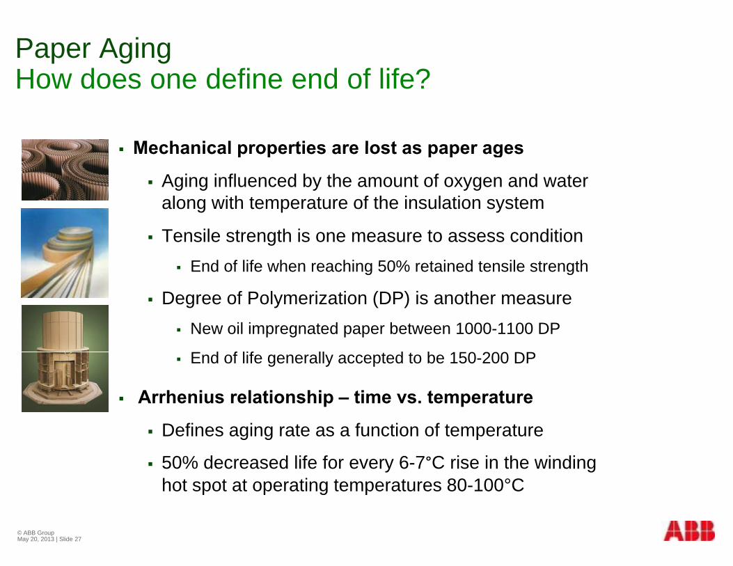
Mechanical properties are lost as paper ages Mechanical properties are lost as paper ages
Aging influenced by the amount of oxygen and water along with temperature of the insulation system
Tensile strength is one measure to assess condition End of life when reaching 50% retained tensile strength
Degree of Polymerization (DP) is another measure New oil impregnated paper between 1000-1100 DP
E d f lif ll t d t b 150 200 DP End of life generally accepted to be 150-200 DP
Arrhenius relationship – time vs. temperature
Defines aging rate as a function of temperature
50% decreased life for every 6-7°C rise in the winding hot spot at operating temperatures 80-100°Chot spot at operating temperatures 80 100 C
© ABB Group May 20, 2013 | Slide 27

BIOTEMP Performance versus Mineral OilSealed tube testSealed tube test
Tensile Strength Tensile Strength
Arrhenius plot of temperature and time to reach 50% retained tensile strength (end of life)
BIOTEMP has a 10°C temperature advantage over
Extended life expectancy at same temperature
10°C
temperature advantage over mineral oil for the same life expectancy
D f P l i ti Degree of Polymerization
Arrhenius plot of temperature and time to reach a DP of 200 (end of life)
BIOTEMP has a 7°C advantage over mineral oil for same life
Extended life expectancy at same temperature
7°C
© ABB Group May 20, 2013 | Slide 28
over mineral oil for same life expectancy

BIOTEMP Performance versus Mineral Oil Functional life testFunctional life test
ABB 4 25kVA 1Ф Transformers ABB 4-25kVA 1Ф Transformers
2 units at 180°C for 2500 hrs
2 units at 200°C for 720 hrs 2 units at 200 C for 720 hrs
IEEE C57.91 estimates 180,000 hrs of life of
Extended life expectancy at same temperature
20°C
expectancy for transformer under normal loading
Units reached end of life as
same temperature
U ts eac ed e d o e asinsulation DP between 185 and 260 at winding hot spot
BIOTEMP advantage of +20°C BIOTEMP advantage of +20 C over similar units specified in IEEE loading guide
© ABB Group May 20, 2013 | Slide 29

Ester Dielectric FluidsIndustry standards activitiesIndustry standards activities
Industry standards have begun to incorporate the properties Industry standards have begun to incorporate the properties and benefits into their technical standards and guides
IEEE C57-154-2012High-Temperature Insulation Systems Annex B - Ester liquid and cellulose paper
IEC TS 60076-14IEC TS 60076 14High-Temperature Insulation Materials Revision incorporating ester fluids to be balloted in 2013
IEEE C57 147 2008 IEEE C57-147-2008Natural Ester Fluid Guide
IEC equivalent to be balloted in 2013q
IEEE PC57.155Dissolved Gas Analysis of natural ester fluids still in working group under development
© ABB Group May 20, 2013 | Slide 30
group under development
Green-R-Trafo BIOTEMP-filled TransformersBenefitsBenefits
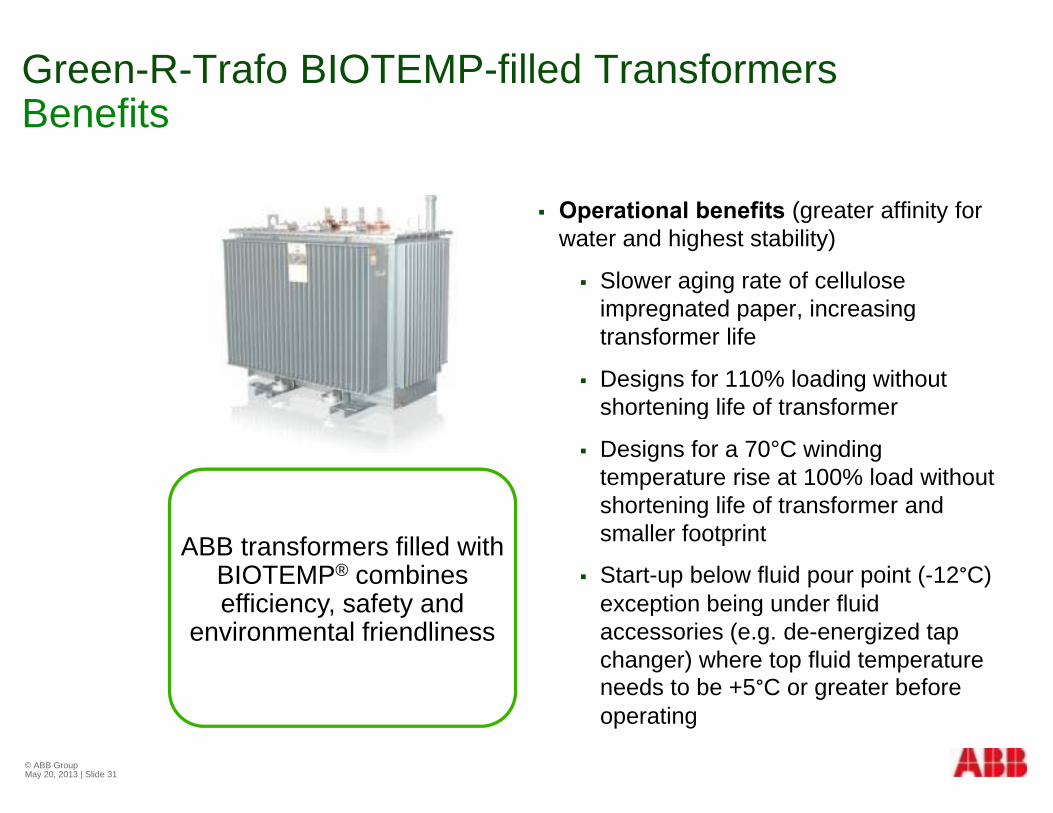
Operational benefits (greater affinity for Operational benefits (greater affinity for water and highest stability)
Slower aging rate of cellulose impregnated paper increasingimpregnated paper, increasing transformer life
Designs for 110% loading without shortening life of transformershortening life of transformer
Designs for a 70°C winding temperature rise at 100% load without shortening life of transformer andshortening life of transformer and smaller footprint
Start-up below fluid pour point (-12°C) exception being under fluid
ABB transformers filled with BIOTEMP® combines efficiency safety and exception being under fluid
accessories (e.g. de-energized tap changer) where top fluid temperature needs to be +5°C or greater before
efficiency, safety and environmental friendliness
© ABB Group May 20, 2013 | Slide 31
operating

Green-R-Trafo™G ee a oGreen transformer programp g
© ABB Group May 20, 2013 | Slide 32

Green Transformer Program Technological solutionsTechnological solutions
© ABB Group May 20, 2013 | Slide 33
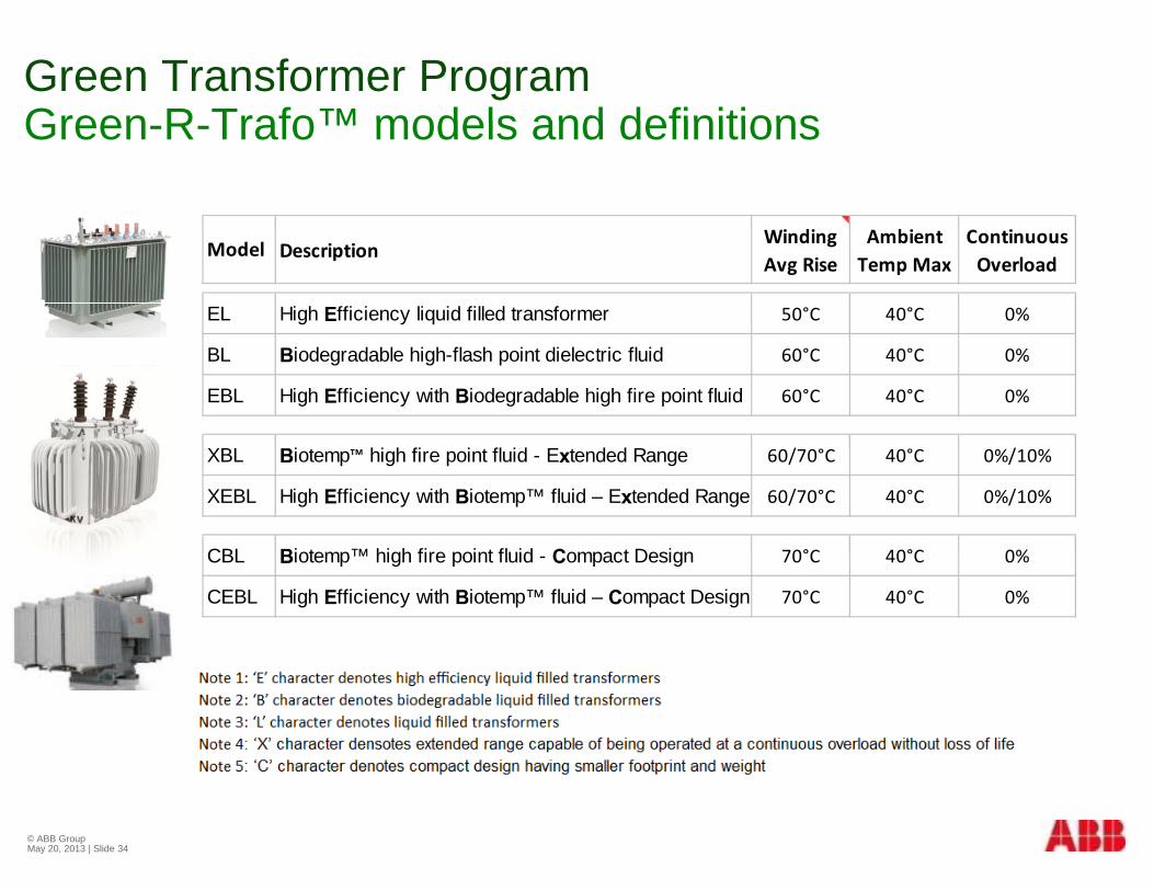
Green Transformer Program Green R Trafo™ models and definitionsGreen-R-Trafo™ models and definitions
i di bi iDescription
Winding Avg Rise
Ambient Temp Max
Continuous Overload
EL High Efficiency liquid filled transformer 50°C 40°C 0%
Model
BL Biodegradable high-flash point dielectric fluid 60°C 40°C 0%
EBL High Efficiency with Biodegradable high fire point fluid 60°C 40°C 0%
XBL Biotemp™ high fire point fluid - Extended Range 60/70°C 40°C 0%/10%
XEBL High Efficiency with Biotemp™ fluid – Extended Range 60/70°C 40°C 0%/10%
CBL Biotemp™ high fire point fluid Compact Design 70°C 40°C 0%CBL Biotemp™ high fire point fluid - Compact Design 70 C 40 C 0%
CEBL High Efficiency with Biotemp™ fluid – Compact Design 70°C 40°C 0%
© ABB Group May 20, 2013 | Slide 34
SummarySu a y
© ABB Group May 20, 2013 | Slide 35
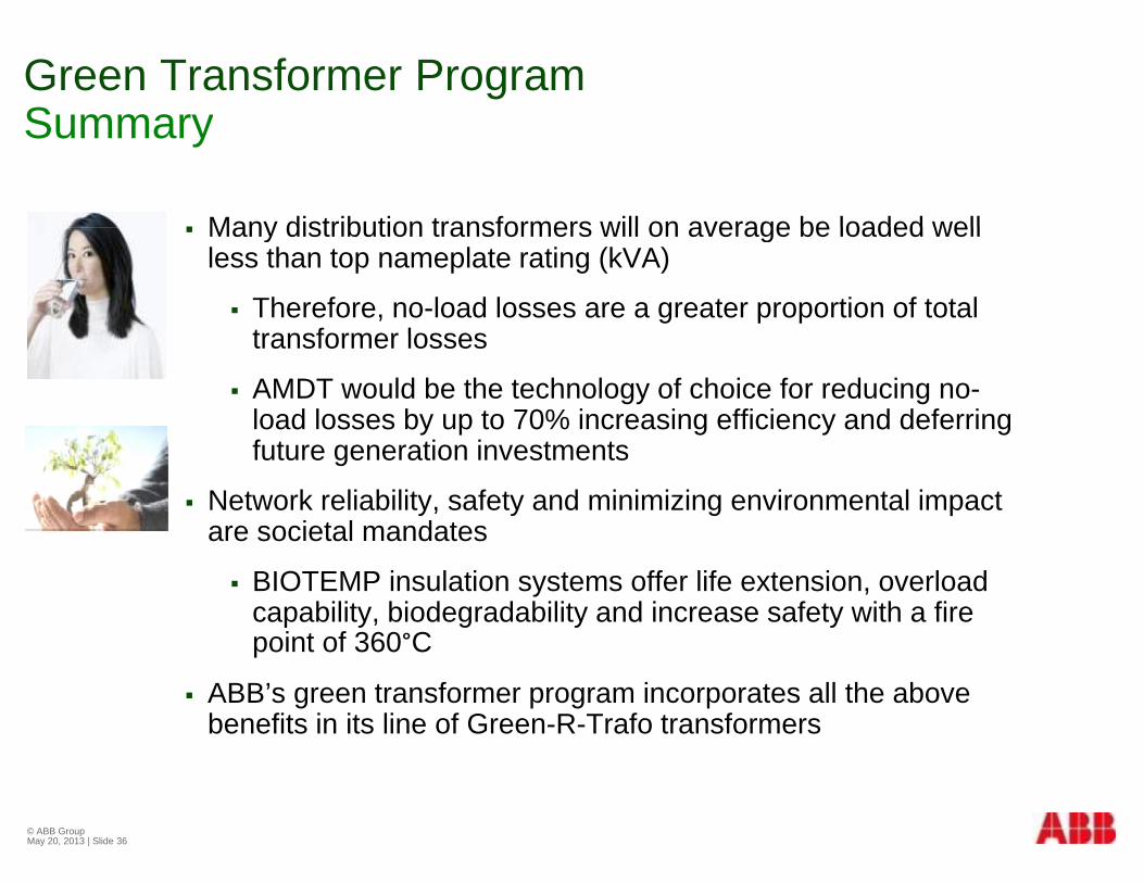
Green Transformer ProgramSummarySummary
Many distribution transformers will on average be loaded well Many distribution transformers will on average be loaded well less than top nameplate rating (kVA)
Therefore, no-load losses are a greater proportion of total transformer lossestransformer losses
AMDT would be the technology of choice for reducing no-load losses by up to 70% increasing efficiency and deferring f t ti i t tfuture generation investments
Network reliability, safety and minimizing environmental impact are societal mandates
BIOTEMP insulation systems offer life extension, overload capability, biodegradability and increase safety with a fire point of 360°Cp
ABB’s green transformer program incorporates all the above benefits in its line of Green-R-Trafo transformers
© ABB Group May 20, 2013 | Slide 36

© ABB Group May 20, 2013 | Slide 37


![Healthy Diet & Lifestyle Choices - RSDSA · Healthy Diet & Lifestyle Choices Philip Getson, D.O. ... YOGA, GARDENING READING ... Getson- Healthy Diet.ppt [Compatibility Mode]](https://static.fdocuments.net/doc/165x107/5b0265e37f8b9a84338f914a/healthy-diet-lifestyle-choices-rsdsa-diet-lifestyle-choices-philip-getson-do.jpg)


