Douglas DC2 for FSX - gotoandflash.comgotoandflash.com/DC2/pic/DC2_manual.pdf · Douglas DC2 for...
41
Douglas DC2 for FSX
-
Upload
vuongthien -
Category
Documents
-
view
238 -
download
1
Transcript of Douglas DC2 for FSX - gotoandflash.comgotoandflash.com/DC2/pic/DC2_manual.pdf · Douglas DC2 for...

Douglas DC2 for FSX

Douglas DC2 for FSX
Thank you for downloading this Douglas DC2 package for Microsoft Flight simulator X.
If you payed for it, ENJOY, if you didn't, and you like it, please re-consider to purchase.
All profit generated by the purchase of this package will be donated to the Aviodrome Dutch National Aviation Theme Park and Museum. The Museum has one ofthe last two airworthy Douglas DC2's in its collection. Your purchase will help to enable them to keep this valuable and priceless aeroplane in flying condition.
These files are copyright by The "UIVER" Team (see credits below). All rights reserved. The contents of this package are not to be reproduced, decompiled, reverseengineered or distributed in any form, manner or fashion without the explicit prior written consent of Rob Cappers. The "UIVER" Team does not guarantee the fitness
of this package for any purpose and does not accept any warranties or liabilities.
Credits:A big thanks to the people of the Aviodrome, for enabling us to take numerous photographs, and helping us with data and input on the flightmodel:
Raymond Oostergo, William Groot, Dick Algra, Peter Baeten, Willem HondersFS Flight Dynamics: Tom Falley, Rob Cappers
DLL programming: HansJörg NaegeleExterior Model: Alexander Schreijnders, Rob CappersLivery: Tim Scharnhop, Gerrit Kranenbarg, Jan VisserVC, Interior: Rob Cappers, Tim Scharnhop, Jan Visser
Effects: Roland Berger, HansJörg NaegeleGauges: XML Programming: HansJörg Naegele, Gauge bitmaps: Rob Cappers, Tim Scharnhop
Modern Avionics: Simflyer and HansJörg NaegeleInterior and exterior custom animations: XML Programming: HansJörg Naegele, Animation modeling: Rob Cappers
Sound Suite: Rob Cappers, Jan VisserManual: HansJörg Naegele, Rob Cappers
Printable Checklist: Howard Sodja, HansJörg Naegele
Testing
Developers and Beta teamPat Cox, Jasper van der Heijden, Wolter van der Spoel, Arjen Dicke, Tom Falley, HansJörg Naegele, Ferry van Orden, Tim Scharnhop, Jan Visser, Roland Berger,
Gerrit Kranenbarg, Roger Law, Howard Sodja.
WebsiteMarieke Hannen, www.mariekehannen.nl
2
Douglas DC2 for FSX
3
Douglas DC2 for FSX
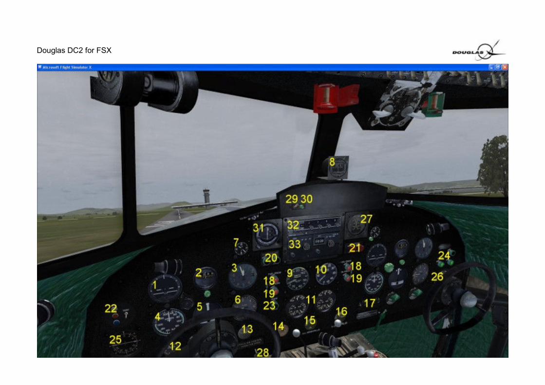
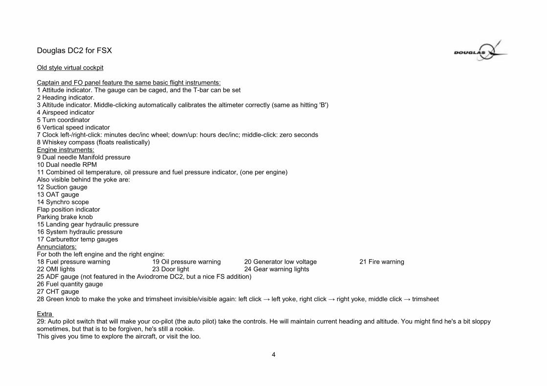
Old style virtual cockpit
Captain and FO panel feature the same basic flight instruments:1 Attitude indicator. The gauge can be caged, and the T-bar can be set 2 Heading indicator.3 Altitude indicator. Middle-clicking automatically calibrates the altimeter correctly (same as hitting 'B')4 Airspeed indicator5 Turn coordinator6 Vertical speed indicator7 Clock left-/right-click: minutes dec/inc wheel; down/up: hours dec/inc; middle-click: zero seconds8 Whiskey compass (floats realistically)Engine instruments:9 Dual needle Manifold pressure10 Dual needle RPM11 Combined oil temperature, oil pressure and fuel pressure indicator, (one per engine)Also visible behind the yoke are:12 Suction gauge13 OAT gauge14 Synchro scopeFlap position indicatorParking brake knob15 Landing gear hydraulic pressure16 System hydraulic pressure17 Carburettor temp gaugesAnnunciators:For both the left engine and the right engine:18 Fuel pressure warning 19 Oil pressure warning 20 Generator low voltage 21 Fire warning22 OMI lights 23 Door light 24 Gear warning lights25 ADF gauge (not featured in the Aviodrome DC2, but a nice FS addition)26 Fuel quantity gauge27 CHT gauge28 Green knob to make the yoke and trimsheet invisible/visible again: left click → left yoke, right click → right yoke, middle click → trimsheet
Extra 29: Auto pilot switch that will make your co-pilot (the auto pilot) take the controls. He will maintain current heading and altitude. You might find he's a bit sloppysometimes, but that is to be forgiven, he's still a rookie.This gives you time to explore the aircraft, or visit the loo.
4

Douglas DC2 for FSX
30 NAV/GPS switchTo the GPS: When connected to the GPS, the NAV1 CDI-needle gives you an idea for your deviation to the GPS track. It does NOT allow you to manually take thebearing to the waypoint ("station"), it's not the way the GPS is used. It is more like approaching a localizer: if the needle rotates to the right, you are left of the GPStrack and therefore have to steer more to the right (and vice versa). Each white point on the NAV1 gauge face corresponds to approx. 1nm deviation. So, withmanual steering, and without looking at the Garmin, you can stay on the GPS track with a precision better than +-0.5nm. Sure, with 120knots IAS, it takes some timeuntil the needle moves, ie. if you are intercepting the track at an angle much less than 90deg, say 30deg.
The Captains panel also features:
31 Special FS NAV Gauge. This gauge is also a little cheat to facilitate more functions
A) Default it shows the NAV 2 gauge (as in the old Aviodrome cockpit) B) Middle click on the OBS knob, and the NAV 1 gauge with glide slope appears.When you hold the mouse over the gauge face, the tooltip shows the ID and the DME of the selected beacon.3D working OBS buttons (left click, right click, mouse wheel scroll to change)
5

Douglas DC2 for FSX
Radios:
32 Transponder
The three positions (OFF, STDBY and ON) need more explanation:The transponder code can be changed only, if the red light is turned on (knob in position ON). Inposition STDBY, the transponder code is set 1200 (and red light off). In position OFF, the broadcasted code is 0000, although the code displayed is 1200. The fourthposition TEST is only for testing the bulb of the red light and has no other function.
After loading a saved flight situation, or after the plane has been loaded, the transponder initializes to OFF, if the transponder code is 0 STDBY, if the transponder code is 1200 ON (red light turned on=active), with every other code.
6
Douglas DC2 for FSX
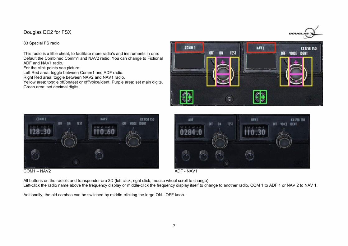
33 Special FS radio
This radio is a little cheat, to facilitate more radio’s and instruments in one:Default the Combined Comm1 and NAV2 radio. You can change to FictionalADF and NAV1 radio.For the click points see picture:Left Red area: toggle between Comm1 and ADF radio. Right Red area: toggle between NAV2 and NAV1 radio.Yellow area: toggle off/on/test or off/voice/ident. Purple area: set main digits.Green area: set decimal digits
COM1 – NAV2 ADF - NAV1
All buttons on the radio's and transponder are 3D (left click, right click, mouse wheel scroll to change)Left-click the radio name above the frequency display or middle-click the frequency display itself to change to another radio, COM 1 to ADF 1 or NAV 2 to NAV 1.
Aditionally, the old combos can be switched by middle-clicking the large ON - OFF knob.
7

Douglas DC2 for FSX
C enter Pedestal: 1 Throttle control (throttle is maximum with the levers pushedforward)2 Prop pitch control (pitch is maximum with the levers pushedforward)3 Mixture control (CAUTION, mixture is maximum with thelevers pulled backwards. )These can be operated per engine separately, or linked. Thiscan be toggled by right clicking the mouse while over thecontrols.
4 Carburettor heat lever5 Fuel tank selector6 Fuel engine selectorTo operate the fuel engine and tank selectors : (left-click - anti-clockwise, right-click – clockwise).7 Fuel dump levers8 Elevator trim9 Rudder trim10 Aileron trim11 Tail wheel lock
Space between seats:12 Flap lever13 Gear lever14 Manual gear pump. 15 Cross feed switch 16 Under the red lid marked Fire extinguishers (click on it toremove the cover): Fire extinguisher switch.
8

Douglas DC2 for FSX
O verhead panel features all the switches:
F rom left to right
1 Landing light left On/Off 2 Landing light right On/Off3 Ship battery / power off / auxiliary power cart
This is a working auxiliary power source.When the parking brake is on, and the switch is set to cart, a power cart is parked in front of the DC2, with the power cable connected.The cart will supply power to the aircraft, when the battery is depleted
4 Radio master switch 5 Inverters (inoperative)6 Hydraulic switch (Hydraulic system is described in detail below) 7 Seat belt / No smoking switch8 Navigation lights Steady / Off / Flashing 9 Remote compass (inoperative)10 Leading edge light (inoperative) 11 Passing light, On / Off12 Rotating Beacon On /Off
9
Douglas DC2 for FSX
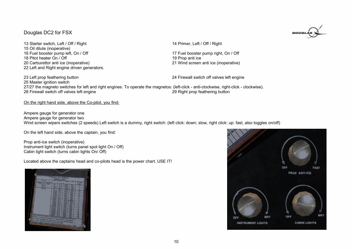
13 Starter switch, Left / Off / Right 14 Primer, Left / Off / Right15 Oil dilute (inoperative)16 Fuel booster pump left, On / Off 17 Fuel booster pump right, On / Off18 Pitot heater On / Off 19 Prop anti ice20 Carburettor anti ice (inoperative) 21 Wind screen anti ice (inoperative)22 Left and Right engine driven generators.
23 Left prop feathering button 24 Firewall switch off valves left engine25 Master ignition switch27/27 the magneto switches for left and right engines. To operate the magnetos: (left-click - anti-clockwise, right-click - clockwise).28 Firewall switch off valves left engine 29 Right prop feathering button
On the right hand side, above the Co-pilot, you find:
Ampere gauge for generator oneAmpere gauge for generator twoWind screen wipers switches (2 speeds) Left switch is a dummy, right switch: (left click: down; slow, right click: up: fast, also toggles on/off)
On the left hand side, above the captain, you find:
Prop anti-ice switch (inoperative)Instrument light switch (turns panel spot light On / Off)Cabin light switch (turns cabin lights On/ Off)
Located above the captains head and co-pilots head is the power chart. USE IT!
10

Douglas DC2 for FSX
11

Douglas DC2 for FSX
Modern VC, as featured in the present day Douglas DC2 of the Aviodrome museum.
1 – 30 are the same as above in the Old style VC:
31 Garmin VOR1by Simflyer32 Garmin VOR2 by Simflyer
3D working OBS buttons (left click, right click, mouse wheel scroll to change)
33 Garmin GMA 340 Audio panel by Simflyer
For the manual see attached PDF from Simflyer
12

Douglas DC2 for FSX
34 Garmin GTX 330 transponder by Simflyer
For the manual see attached PDF from Simflyer
35 Garmin GNS 430 GPS by Simflyer
For the manual see attached PDF and video from Simflyer
3D working buttons (left click, right click, mouse wheelscroll to change)
36 Bendix King KX 165A TSO The modern model Bendix radio is a COM1/NAV2 combo(and FS cheat for enhanced functionality, like the old styleradio) The COM1 can be switched into an ADF 1 radio, and theNAV 2 into a NAV 1. To do this, either left-click the radioname (COMM, NAV), or middle-click into the frequencywindows.
3D knobs to operate the radio. (left click, right click,mouse wheel scroll to change)
Radio cannot be switched off, due to compatibility with theGarmin GPS.
When the COM 1 or NAV 1 frequencies are set using theSimFlyer GPS, the standby frequency is set and thenmust be made active.
13

Douglas DC2 for FSX
1. SYSTEMS DESCRIPTION
HYDRAULIC SYSTEMThe hydraulic system is of constant pressure type and consists of two electricallydriven pumps. The main pump is providing hydraulic pressure for operation oflanding gear, wing flaps, and wheel brakes, while the other auxiliary pump isentirely separate and only supplies the wheel brakes in the event of the mainpump or hydraulic system failed. There are no engine-driven hydraulic pumps.Normal system pressure is between 650 and 800 psi. Either one of the pumps canbe toggled by the selector switch (Fig. 1-1) on the overhead panel.This switch must be in position MAIN (up), except in emergency, when the mainpump has failed and must be switched off. To use the auxiliary hydraulic pump,simply place the switch to AUX position during periods of required brakeapplication.NOTE - REMEMBER THIS AUXILIARY HYDRAULIC PUMP OPERATESBRAKES ONLY.The hydraulic system may take damage, if gear or flaps are operated at too high
airspeed (see limits section). The hydraulic system also fails if there is not enoughelectrical power available, ie. due to generator failure.Other possibilities are failures invoked using the FSX failure menu.A hydraulic hand pump (Fig. 1-2) is available to furnish hydraulic pressure forlanding gear operation, flaps, or brakes in case of failure of the electric pump. Forthis to work, the hydraulic shut-off valve (Fig. 1-3) must be closed when the handpump is to be used.Left-clicking the hand pump causes the hand pump to move once, while middle-clicking lets it pump from alone unless it is clicked again.At least 650 psi must be created by the hand pump to allow operation of gear,wing flaps and brakes.A failed hydraulic system may be reset by closing and re-opening of the hydraulicshut-off valve (Fig. 1-3). After turning on the main electrical hydraulic pump, waitsome time until enough hydraulic pressure has built, and gear, flaps or brakesshould be operative again.
14
Douglas DC2 for FSX
NOTE - THE HYDRAULIC SHUT-OFF VALVE MUST BE OPEN WHEN THE MAIN ELECTRICAL PUMP IS USED AND CLOSED AT ALL TIMES WHEN THEHYDRAULIC HAND PUMP IS NEEDED.
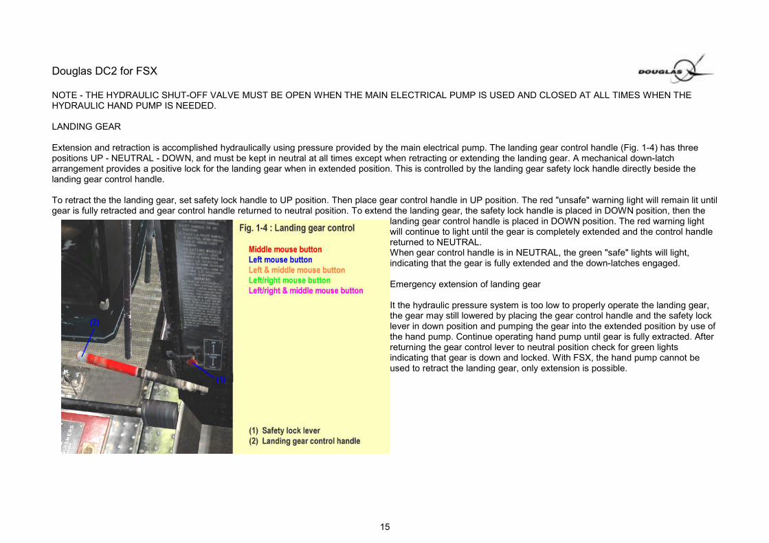
LANDING GEAR
Extension and retraction is accomplished hydraulically using pressure provided by the main electrical pump. The landing gear control handle (Fig. 1-4) has threepositions UP - NEUTRAL - DOWN, and must be kept in neutral at all times except when retracting or extending the landing gear. A mechanical down-latcharrangement provides a positive lock for the landing gear when in extended position. This is controlled by the landing gear safety lock handle directly beside thelanding gear control handle.
To retract the the landing gear, set safety lock handle to UP position. Then place gear control handle in UP position. The red "unsafe" warning light will remain lit untilgear is fully retracted and gear control handle returned to neutral position. To extend the landing gear, the safety lock handle is placed in DOWN position, then the
landing gear control handle is placed in DOWN position. The red warning lightwill continue to light until the gear is completely extended and the control handlereturned to NEUTRAL.When gear control handle is in NEUTRAL, the green "safe" lights will light,indicating that the gear is fully extended and the down-latches engaged.
Emergency extension of landing gear
It the hydraulic pressure system is too low to properly operate the landing gear,the gear may still lowered by placing the gear control handle and the safety locklever in down position and pumping the gear into the extended position by use ofthe hand pump. Continue operating hand pump until gear is fully extracted. Afterreturning the gear control lever to neutral position check for green lightsindicating that gear is down and locked. With FSX, the hand pump cannot beused to retract the landing gear, only extension is possible.
15

Douglas DC2 for FSX
WING FLAPS
The wing flaps lever (Fig. 1-5) has three positions UP - NEUTRAL - DOWN. Eachmovement of the lever to DOWN position, increases the flaps by one stage, whileUP is reducing the flaps to the next lower position, provided that sufficienthydraulic pressure is available.The lever automatically returns to neutral position if the next higher or lower flapstage has been reached. While wing flaps are not to be used for take-off, theyshould be used for all landings. When extending flaps, they should be fullyextended (there is no particular gain with this airplane in using partial flapextension).
NOTE - DO NOT EXTEND THE FLAPS COMPLETELY ABOVE 87 KNOTS IAS(HYDRAULIC SYSTEM MAY TAKE DAMAGE).
BRAKE SYSTEM
The brakes are conventional hydraulic brakes, individually controlled by the rudderpedals. At least 650 psi hydraulic pressure must be provided by the regularhydraulic system to make the brakes fully operative. Emergency pressure isavailable by use of the hydraulic hand pump (Fig. 1-2) or the emergency electricpump (Fig. 1-1). Parking brakes are operated by pulling out the parking brakehandle (Fig. 1-6) in front of the pilot. To release parking brakes, simply push downon the brake pedals.
16

Douglas DC2 for FSX
FUEL TANKS
The fuel system consists of four fuel tanks located in the center section of the wing. There are two main fuel tanks, and two auxiliaries, with capacities as follows:1. Left Main - 180 gallons2. Right Main - 180 gallons3. Two auxiliaries - 75 gal. each (connected to common line)
Total tank capacity is 510 gal. Fuel pressure for the engines is provided by an engine-driven fuel pump on each engine. Additionally, there are two electrical boosterpumps installed, but only for temporary use, during engine start or if another fuel tank is selected.NOTE - ELECTRICAL BOOSTER PUMPS MAY OVERHEAT AND FAIL IF LEFT ON LONGER THAN 5 MINS
A single tank selector valve (Fig. 1-9) on the left top of the control pedestal allows fuel to be fed from either main tank (position LEFT or RIGHT) or from bothauxiliaries (position AUX) as desired. The right auxiliary tank drains into the left aux, from where the fuel is transferred to the tank selector switch. Since there is onlyone tank selector for both engines, it is impossible to run the engines on different tanks. This implies, that the tank selector positions LEFT and RIGHT cause anunbalanced weight situation, while in position AUX, both auxiliary tanks are emptied simultaneously.The right main tank is selected automatically as current tank, if the aircraft is loaded with a fuel tank selector position, which is not used on that aircraft.From the tank selector switch, the fuel is pipe lined to the engine selector switch (Fig. 1-9), located on the opposite side of the pedestal, permitting fuel to be fed toeither or both engines. A closed fuel valve causes the engine to be cut off fromany fuel (exception: cross feed switch open, see below). Therefore, the normalposition is BOTH ON, while LEFT ENGINE ON, RIGHT ENGINE ON are usedonly in emergency, if one engine has failed.NOTE - NEVER SWITCH TO AN OTHER TANK WITH ELECTRICAL BOOSTERPUMPS TURNED OFF.
If you switch to an empty tank (wrong decision), the engine won't stallimmediately, because there is some fuel left in the lines which is burned first.Within that short period of time, you can revise your decision, if you becomeaware, that you moved the switch into the wrong direction. After the engine selector switch, each engine has its own fuel line, transferring thefuel to the booster pumps and to the carburettor. However, a connection betweenthese two separate fuel lines can be opened with the cross feed switch (Fig. 1-7,and "OMLOOPKRAAN"). This allows to transfer fuel from one engine's fuel line tothe other in case of a single fuel pump failure, so that the remaining pump can beused for both engines. Note, the cross feed valve is located between the engineselector switch and the carburettors, therefore it neither allows to equalize tanksnor does it influence in any other way from which tank the fuel is currently taken(tank cross feed). It is used only in emergency to allow the remaining fuel pump tosupply fuel to the other engine.
17

Douglas DC2 for FSX
If one fuel pump fails: 1. Set booster pump switch of the failed pump to OFF 2. Open the cross feed valve (control switch located on floor at left front corner of co-pilot's seat)3. Close the fuel valve of the engine with the failed pump (set engine selector switch to LEFT ENGINE ON if the right fuel pump fails, and to RIGHT ENGINE ON if the left fuel pump is not working.
FSX can simulate a single booster pump failure, and you will notice an increasing fuel press on the engine with the not working fuel pump, when the cross feed valveis opened.Users who have activated the "virtual co-pilot" feature, may get "low fuel" warnings, if tank selector is set to position AUX, no matter if aux tanks are empty or full.This wrong message is caused by a problem from within FS, so this warnings can be ignored, instead, use fuel quantity gauge and trim sheet to get preciseinformation about the current tank level.
A fuel dump valve is installed on the right main tank, controlled by two push-pull controls (Fig. 1-9). The one on the left pedestal opens the dump valve, and pullingon the right side control closes the dump valve (dumping speed is approx. 50 gals per min).NOTE - OPENING THE DUMP VALVE WILL DUMP ALL FUEL IN THE RIGHT MAIN TANK.ELECTRICAL SYSTEM
Electrical power is supplied by a 24 volt battery, and two generators, one on eachengine. It is possible to start engines using thebattery only without ground power. However, for this to work, the battery must befully charged (battery voltage > 23 volts). Toconnect the airplane to an external power source (power cart), parking brakesmust be set and the battery master switch (Fig. 1-8)set to CART. With the switch in CART position, a depleted ship battery is chargedby the power cart.
18
Douglas DC2 for FSX
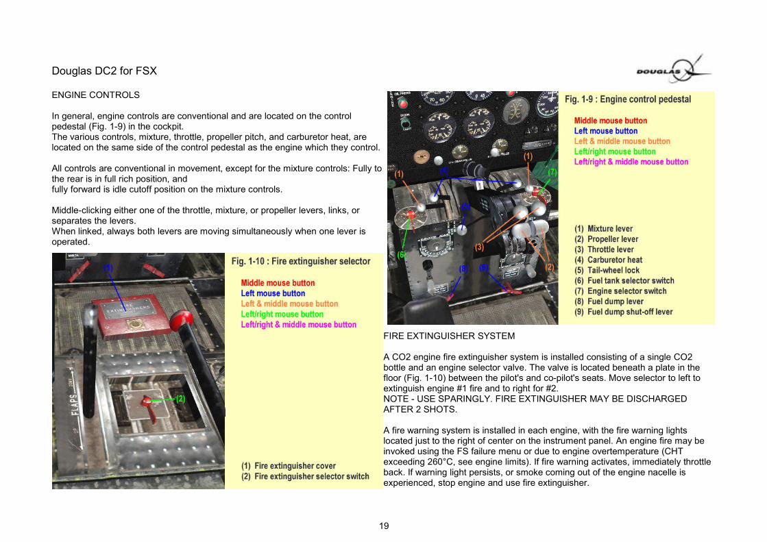
ENGINE CONTROLS
In general, engine controls are conventional and are located on the controlpedestal (Fig. 1-9) in the cockpit. The various controls, mixture, throttle, propeller pitch, and carburetor heat, arelocated on the same side of the control pedestal as the engine which they control.
All controls are conventional in movement, except for the mixture controls: Fully tothe rear is in full rich position, andfully forward is idle cutoff position on the mixture controls.
Middle-clicking either one of the throttle, mixture, or propeller levers, links, orseparates the levers.When linked, always both levers are moving simultaneously when one lever isoperated.
FIRE EXTINGUISHER SYSTEM
A CO2 engine fire extinguisher system is installed consisting of a single CO2bottle and an engine selector valve. The valve is located beneath a plate in thefloor (Fig. 1-10) between the pilot's and co-pilot's seats. Move selector to left toextinguish engine #1 fire and to right for #2.NOTE - USE SPARINGLY. FIRE EXTINGUISHER MAY BE DISCHARGEDAFTER 2 SHOTS.
A fire warning system is installed in each engine, with the fire warning lightslocated just to the right of center on the instrument panel. An engine fire may beinvoked using the FS failure menu or due to engine overtemperature (CHTexceeding 260°C, see engine limits). If fire warning activates, immediately throttleback. If warning light persists, or smoke coming out of the engine nacelle isexperienced, stop engine and use fire extinguisher.
19
Douglas DC2 for FSX
STARTING ENGINES
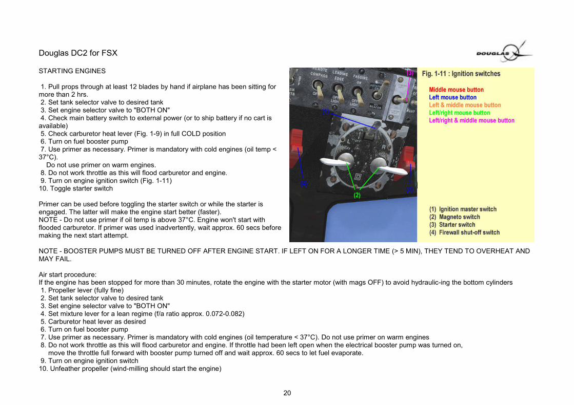
1. Pull props through at least 12 blades by hand if airplane has been sitting formore than 2 hrs. 2. Set tank selector valve to desired tank 3. Set engine selector valve to "BOTH ON" 4. Check main battery switch to external power (or to ship battery if no cart isavailable) 5. Check carburetor heat lever (Fig. 1-9) in full COLD position 6. Turn on fuel booster pump 7. Use primer as necessary. Primer is mandatory with cold engines (oil temp <37°C). Do not use primer on warm engines. 8. Do not work throttle as this will flood carburetor and engine. 9. Turn on engine ignition switch (Fig. 1-11)10. Toggle starter switch
Primer can be used before toggling the starter switch or while the starter isengaged. The latter will make the engine start better (faster).NOTE - Do not use primer if oil temp is above 37°C. Engine won't start withflooded carburetor. If primer was used inadvertently, wait approx. 60 secs beforemaking the next start attempt.
NOTE - BOOSTER PUMPS MUST BE TURNED OFF AFTER ENGINE START. IF LEFT ON FOR A LONGER TIME (> 5 MIN), THEY TEND TO OVERHEAT ANDMAY FAIL.
Air start procedure:If the engine has been stopped for more than 30 minutes, rotate the engine with the starter motor (with mags OFF) to avoid hydraulic-ing the bottom cylinders 1. Propeller lever (fully fine) 2. Set tank selector valve to desired tank 3. Set engine selector valve to "BOTH ON" 4. Set mixture lever for a lean regime (f/a ratio approx. 0.072-0.082) 5. Carburetor heat lever as desired 6. Turn on fuel booster pump 7. Use primer as necessary. Primer is mandatory with cold engines (oil temperature < 37°C). Do not use primer on warm engines 8. Do not work throttle as this will flood carburetor and engine. If throttle had been left open when the electrical booster pump was turned on, move the throttle full forward with booster pump turned off and wait approx. 60 secs to let fuel evaporate. 9. Turn on engine ignition switch10. Unfeather propeller (wind-milling should start the engine)
20

Douglas DC2 for FSX
When the engine does not start:
If start problems are experienced, further attempts should be made using the mouse areas of the control panel (Fig. 2-2).It allows a better overview of the relevant settings (wrong positions may be indicated in red font), and the tooltip of the click area activating the starter motor on thestarter table (Fig. 2-4) serves as your "engine start assistant": The tooltip tells if the engine will start or what has to be changed for a successful attempt. In detail,following error messages are displayed by the tooltip:
! Reduce Altitude
The aircraft is flying too high (above 13,000ft) for an engine start.
! Crash Landing
Engines are damaged due to a belly landing before. You must load an other flight situation or reset the current situation, ie. by middle-clicking the "CLOSE"-button of the trim sheet.
! Bus Voltage
Starter motor won't activate if the available electrical power is below 23 volts. When reading this message, check if the battery is turned on and not depleted.With low battery, connect to external power by setting the battery switch to CART(parking brake must be set). If one engine is already running, turn on thegenerator of that engine.
! Toggle Firewall Shut-off Switch
The engine is cut-off from any fuel because its firewall shut-off valve is closed. Open the valve by toggling the switch (Fig. 1-11).
! Check Fuel Tank Selector Switch
The fuel tank selector switch is turned OFF, or a tank with no fuel has been selected.
! Check Engine Selector Switch
Make sure that the engine selector switch is set to position "BOTH ON".
! Check Carb Heat Position
For engine start on ground, needed carburetor heat position is COLD (Fig. 1-9)
21

Douglas DC2 for FSX
! Close Throttle LeverAn opened throttle lever will flood carburetor. Close throttle and wait until the tooltip no longer displays this error message.
! Open Mixture LeverThe fuel-air-ratio is too lean for an engine start. Open the mixture lever to full rich or at least to the extent that the f/a ratio readout value (Fig. 2-6) is notdisplayed in red font.
! Unfeather PropThe propeller is still feathered.
! Rotate Prop with Starter The feathering inhibit flag is not set although the propeller is unfeathered. Feather again, activate starter a few seconds to rotate propellers.
Important: Before pulling the feather button, wait until propeller has come to a stop. ! Toggle Booster Pump
Fuel lines may be empty or partly filled with air. Toggle electrical booster pump.
! Toggle Master IgnitionThe master ignition switch is set OFF (Fig. 1-11)
! Check Magneto SwitchFor engine start, the magneto switches must be in position BOTH (Fig. 1-11)
! Wait - Carburetor floodedCarburetor or engine is flooded, ie. due to use of too much primer or if throttle lever was left open more than 10% with booster pump turned on.Wait until engine has cooled down (oil temperature < 37°C), or until message isn't displayed anymore (can take about one minute after inadvertent use of primer).However, waiting time may be much longer, if engine was flooded because booster pump has been turned on and the throttle lever was not closed before.In that case, the waiting period can be drastically reduced, if booster pumps are turned off and throttle is opened as much as possible to allow the flooded fuel to evaporate out of the carburetor. Then, the next start attempt can be made as soon as the start assistant tooltip calls for closing the throttle lever.
! Use PrimerCold engine, primer is needed (before or while activating the starter motor)
If the tooltip just reads 'Starter' (and starter column readout is not in red font), no error was detected and the engine should start. However, there is one possibility leftfor an unsuccessful start attempt: The starter motor torque may be too low. Check engine RPM (tachometer) readout on the power table (Fig. 2-6) to confirm thatwith activated starter motor at least 375 RPM are reached, which is the minimum needed for a start. If not, you must edit the AIRCRAFT.CFG and increase thestarter torque [piston_engine]-section: normalized_starter_torque=0.3 Increase to 0.5 or higher (until engine starts).
22
Douglas DC2 for FSX
ENGINE WARM UP
After engine start, oil pressure should show within 30 secs or engine should be stopped and checked. Keep engine RPM under 400 until oil pressure is at least 15-20 psi. Warm-up engines at 500-1000 RPM. Normal oil pressure during warm-up and flight is about 65 psi.
Monitor cylinder head temperature closely while on ground as there is very little cooling during ground operation. Minimum take-off CHT is 148°C. If absolutemaximum CHT (260°C) is exceeded, engine may take damage or catch fire (see engine limits)
TAXIING
When taxiing, speed should be maintained at a low enough value that control is available through use of throttles only.Brakes should be used sparingly. Keep tail wheel locked (Fig 1-9) during all straight taxiing, unlocking it only when necessary to turn the airplane. When turning, donot lock the inner wheel as it is to hard on tires and landing gear. Keep it rolling slightly at all times.
TAKE-OFF
After taxiing into take-off position, roll airplane forward in a straight line for a short distance to engage tail wheel lock. Wing flaps are not to be used during take-off.Advance throttle slowly and evenly until maximum take-off manifold pressure of 37 inHg is reached. As soon as the airplane is airborne, lower nose slightly andretract landing gear immediately. Hold nose down until best climbing airspeed of 87 KIAS is reached then proceed into normal climb.
NOTE - THROTTLE BACK FROM TAKE-OFF POWER TO METO (CLIMB) POWER AS SOON AS POSSIBLE. ENGINES MAY TAKE DAMAGE WHENOPERATED AT MAX POWER (SEE ENGINE LIMITS).
STOPPING ENGINES
Engines should be idling, and the mixture controls should be moved to idle cut-off (fully forward). Ignition switches (Fig. 1-11) should be turned off after propellershave quit rotating.
23

Douglas DC2 for FSX
OPERATING LIMITS AND FAILURES:
Airspeed: Level flight (Vno): 165 KIAS Glide or Dive (Vne): 204 KIAS Flap Extension (Vfe): 87 KIAS Landing Gear (Vle): Vne (no limit, gear may be used as speedbrake) V1 & V2: 69 KIASNOTE - HYDRAULIC SYSTEM MAY TAKE DAMAGE AND FAIL IF WING FLAPS ARE COMPLETELY EXTENDED ABOVE 87 KIAS.
Engine: Take-off : 37inHg, 2350 RPM (SL: 2 mins) In-flight emergency : 37 inHg, 2360 RPM (7.500ft, 5 mins) Max. Continuous (Meto) : 32 inHg, 2300 RPM (SL), 27.9 inHG, 2300 RPM (13.300 ft) Straight line variation of MAP between these altitudes Min. oil temp : 37°C (take-off) Max. CHT : 260°C Min. CHT : 148°C (take-off) Min. oil pressure : 45psi Min. fuel pressure : 5psiNOTE - EXCEEDING MAP OR RPM TIME LIMITS FOR TAKE-OFF AND METO CLIMB MAY DAMAGE ENGINES AND CAUSE FAILURE.NOTE - CHT OVERTEMPERATURE DRASTICALLY INCREASES THE RISK OF ENGINE FIRES.
Weight: Max. take-off: 18560 lbs. Landing weight: 18000 lbs. Baggage (aft): 1000 lbs. Baggage (fwd): 315 lbs.
Other limits: Min. hydraulic press : 650 psi Max. hydraulic press : 800 psi Minimum voltage required for starter motor: 23V Time limit electrical booster pumps: 8 mins
NOTE - USE BOOSTER PUMPS SPARINGLY AND ONLY WHEN NEEDED (ENGINE START, TANK SWITCHING). THEY CAN OVERHEAT AND FAIL. IN THATCASE, TURN OFF AND WAIT UNTIL PUMP HAS COOLED.
24

Douglas DC2 for FSX
THE WAY TO HANDLE THE DOUGLAS DC2: (by William Groot, Aviodrome DC2 pilot)
Taxi:Pull back your yoke, to keep that tail wheel on the ground at all times. Steer with differential brakes and differential throttle.
Before Take off:What you do need to be careful with is climb and trim settings.Initial trim settings can be read from the trim sheet. (shift-3). Here you can read the Center of Gravity with different loads. It will also indicate an advised trim settingfor Take Off. Trim can easily be set in the VC.
Take off:Throttle up to 37”MAP, 2350RPM, no flaps. @ 30 knots, give a bit of forward stick, to get the tail up, and then accelerate more to an airspeed for take off @ minimum65 knots. After 65 knots it will go airborne, stay level to gain climb speed . Blue line on airspeed indicator .Remember, stall speed is about 40 knots, don’t take off sooner than 65 knots. Not a good idea. Don't use flaps, you don't need that. Flaps on take-off, and a lowtake-off speed are inadvisable, in case of engine failure, you need to have some margin. So: take off clean.Direct after Take Off: gear up, set max extended take off power 32” and 2300 RPMAt safe altitude (500 ft AGL) : Climb settings: 30" and 2000 RPM (see reference sheet, this measures 675 HP. During climb, keep your hand on the elevator trim,and trim her gently to get a climb speed of 800-1000 fpm. Airspeed 105 knots during climb.Don’t fly with full throttle for more than a few minutes. The engines WILL fail. Than the fire extinguisher WILL come in handy. Throttle back to climb settings soonafter you have your gear up. Adjust mixture during climb as necessary.
Cruise:Reaching cruise altitude go to cruise settings: 27"and 1850 RPM (600 HP) also see ref. Sheet.
Descend:For descend reduce throttle. First to 20” 1850 RPM.Down wind leg:First slow down in airspeed during level flight. Mid down-wind: gear down (2 green lights). Adjust speed with throttle to maintain a speed of 100 knots, due toincreased drag by the gear. End of down-wind speed 100 knots. Set flap 15°.Base leg:Set flaps 25°. On base leg, reduce airspeed to 80 knots, and keep reducing throttle to have a descend rate of 500 fpm. .On Final:
Props to High RPM. Reduce airspeed to 65 knots (safety margin)Full FlapsFinal Check: Fuel booster pumps onFull flapsLanding clearanceThreshold speed 65 - 60 knots
25

Douglas DC2 for FSX
Landing:Always make a main wheel landing (NEVER a three point landing)@ 30 knots, push the tail wheel down (stick back)
End of landing roll on the runway, prior to taxi: Flaps up, Fuel boost pumps off ,Tail wheel lock off
ENGINE FAILURE IN FLIGHT
- Both Props 2300 throttle 32” than look to indicators and feel the paddles- Retard the throttle of the suspected engine- Feather the prop to reduce drag on failed engine- Mixture control to idle cut-off- Safe the live engine, reduce if you can but maintain airspeed- Verify that engine rotation has ceased. Look outside or check the tachometer.- Magnetos off- Fuel selector for that engine to OFF; Generator OFF.
In case of engine fire, put out the fire with the fire extinguishersIf fire persist shut off fuel to the engineIf engine 1 fails, you have to switch to the alternate vacuum source, to keep the vacuum powered flight instruments running, and the Autopilot active.If both engines fail, you can still get the gear down by manually pumping down the gear. Manual gear down: Safety lock down, gear handle down, move the hand pump lever left of the co-pilot seat until the gear is completely down, gear handle back toneutral. (2 green lights)
26

Douglas DC2 for FSX
2. TRIMSHEET & CONTROL PANEL POPUP
The trimsheet popup consists of two pages, page 1 shows fuel, weights, and trim data, while page 2 is a control panel monitoring almost all relevant flightinstrumentation data. Both pages offer several mouse (click-)areas for multiple action, so that the aircraft can (almost) be operated completely from within this popuppanel. With the aircraft on ground, it is possible to change payload weights and fuel tank contents. After the DC-2 has been selected in the aircraft menu, thetrimsheet popup is loaded once in place of the 2D-panel. It remains visible in all views (VC, fly-by, tower etc.) until it is closed.Refer to the following descriptions and illustrations for details on what mouse events are accepted by which areas: Often, a middle-click (push mouse-wheel)changes the unit of a displayed readout value, ie. fuel can be viewed as gallons or pounds (lbs). Also, in many cases, the mouse event wheel-down triggers thesame action than a left-click and mouse wheel up is equivalent to a right-click.
TRIMSHEET (PAGE 1)
(1) Clicking into the flight number opens or closes the FS ATC-window. This field is also visible on the control panel (page 2).
(2) The tank currently feeding is displayed in yellow font color. Aleft-click into the tank name selects it asnew tank feeding the engines. Please note, that the electricalbooster pumps must be turned on at the time another tank isselected, otherwise the engines may stall (also refer to fuelsystem section).
(3) Indicates the fuel quantity left in a tank. If it's the tank currentlyfeeding, the amount of fuel is displayed yellow(red if there are less than 10 gallons left). If the aircraft is onground, it is possible to change the content of a tank.Each left-/right-click causes the fuel to be inc-/decreased by 5gallons. The fuel quantities also can be middle-clickedto change the unit of display: By default, fuel is showed in"galllons", but it also is possible to display "lbs", "percent oftank capacity", and "remaining air time". The latter is the timebased on the current fuel flow until the tank will be empty.
(4) While it is possible to change the content of each tankseperately by clicking into the fuel quantity, it also is possible toapply pre-defined fuel configurations: Repeat clicking with left orright mouse button into the "Total fuel:" field. When clicked, thefield will change to "Select fuel:" in blue color and offers on theright side (5) one of the pre-defined fuel configurations, which are
27

Douglas DC2 for FSX
"MAX", "NORM", "PATTERN", and "EMPTY". Middle-click field (4) while it is in blue color to choose the selected configuration displayed in (5): If "MAX" is chosen, allfour tanks are filled 100%, "PATTERN" selects minimum fuel for a short flight only, while "NORM" applies medium fuel load allowing more payload capacity. Use"EMPTY" to remove all fuel from the tanks ("EMPTY" additionally is setting the plane into a "cold & dark" condition).
(5) Adds the amount of fuel in all four tanks (total fuel). The field can be middle-clicked to change between "gallons", "pounds", "percentage of total capacity" and"remaining air time". If a pre-defined fuel config is selected using field (4), one of "MAX", "NORM", "PATTERN", and "EMPTY" is displayed in blue color instead ofthe total fuel quantity.
(6) The weight of each payload station can be changed by a left- or right-click. Each left-click decreases the weight by 10 pounds, each right-click increases it. Note,that payload changes are only possible if the aircraft is on ground. The maximum weight allowed for a station is limited to 315 lbs for "Mail" (fwd station), 1000 lbs for"Luggage" (aft station), and not more than 400 lbs for each passenger row (see also limits section). When loading the aircraft, take care to keep total weight underthe maximum allowed gross weight, and CG (center of gravity) within envelope. Also, ensure that the maximum landing weight won't be exceeded at the final stageof flight.
(7) Similar to the pre-defined fuel configurations, there is also the possibility to choose a pre-defined payload config: Repeat clicking with left or right mouse buttoninto the "Total payload:" field. When clicked, the field will change to "Select payload:" in blue color and offers on the right side one of the pre-defined configurations,which are "PASS", "FREIGHT", "HEAVY", "LIGHT", and "EMPTY". Middle-click "Select payload:" while it is in blue color to choose the offered configuration on theright side: If "PASS" is chosen, all payload weights are set exactly like specified in the AIRCRAFT.CFG, so that this is equivalent to the default configuration whenthe aircraft has been selected in the FS aircraft menu. Note, that with "HEAVY" the maximum take-off weight will be exceeded with no fuel removed from the tanks.The total weight readout value (shown below the total payload weight) is displayed in red color, if maximum gross weight is exceeded. When the font is green, totalweight is under the maximum landing weight (see limits section).
(8) Elevator (pitch) trim position in degrees. Left-clicking is increasing nose-down attitude, and right-clicking trims nose up. A middle-click zeros pitch trim. Use therecommended trim setting for take-off which is shown directly above the current trim position.
The clock (9) can be right-clicked to change between normal clock and a timer. Left-clicking activates or stops the timer. Font color is white (clock selected), yellow(timer selected), and green (timer is running). A middle-click zeros the timer. The clock is also visible on page 2 of the trimsheet.
The "CLOSE" button (10) is used to close the popup-panel. When middle-clicked, additionally the current flight situation is rewinded to the beginning (ie. this is usefulto proceed after a crash landing).
Left-/right clicking the "NEXT" or "PREV" button (11) selects either page 1 (trimsheet) or page 2 (control panel).
28

Douglas DC2 for FSX
CONTROL PANEL (PAGE 2)
The control panel consists of nine tables, each of them iscollecting a couple of related data and parameters for easymonitoring and control, ie. for engine start, fuel management,power setting and autopilot control. Many fields andtable columns can be clicked to trigger an action, ie. to toggle thecorresponding switch or handle. Also, often the headerof a column field can be middle-clicked to change the unit ofdisplay or to show different readout data in the field below.For more details, refer to the following description of each table.
29

Douglas DC2 for FSX
ELECTRICS TABLE
(1) Shows battery voltage in red (depleted, external power isneeded for starter motor), green (battery fully charged),or yellow (low voltage, must be charged) color. Clicking into thefield toggles master battery switch (Fig. 1-8) between SHIPand OFF position.
(2) External (ground) power voltage. Left-click to toggle batteryswitch CART - OFF.
(3) Main bus voltage is displayed in red color if voltage is too lowfor starter motor, and green if voltage is high enough tocharge battery, otherwise font color is yellow.
(4) Click to toggle radio master switch ON - OFF. Font color isred, if avionics bus voltage is too low (< 17V). Yellowindicates a voltage lower than normal.
(5) Left-click to toggle both landing lights on/off.
(6) Toggles the navigation, leading edge, passing, and beaconlights. (leading edge light is inoperative).
(7) Cockpit & cabin lights toggle
30

Douglas DC2 for FSX
STARTER TABLE
(1) Yellow or red font indicates that engine has failed (color is redif aircraft is flying)
(2) Toggles firewall shut-off valve (Fig. 1-11). Red color indicates aclosed valve.
(3) Shows state of electrical booster pumps. With engine notrunning, font is red if pump is turned off (because booster pumpsare needed for start). Yellow indicates that pump is turned on.With engine running, the color may change from yellow to red ifpump is left on too long and overheating. In that case, immediatelyturn off booster pump and let it cool down. Left-clicking toggles thebooster pump switch ON - OFF, middle-click into field to turn on/offthe automatic activation of booster pump when starter switch isengaged.
(4) Generator voltage is displayed red if voltage is too low forcharging the battery. Clicking the field toggles the generatorswitch.
(5) This column displays the position of the engine magnetoswitches (OFF - LE - RI - BTH). When color is red, either themaster ignition switch (Fig. 1-11) or the engine magneto switch isin position OFF. Middle-click to operate the master ignition switchor right-/left-click to inc-/decrease the magneto switch position.
(6) Click to toggle engine primer. If primer is needed for engine start depends on oil temperature, do not use primer with hot engine (oil temperature > 37°C).Therefore, font is red if engine is cold and primer is mandatory, or when engine is hot and primer has been used inadvertently (in that case, wait until color changesto white).
(7) Left-clicking activates, middle-clicking stops the starter motor. If starter field is red, engine very likely won't start because of a wrong setting. Follow engine startchecklist to be sure to have all levers and switches set correctly for a successful engine start. When font color is red, use tooltip to find out what setting is wrong (seeengine start procedure for a complete list of all possible error messages and what to do to clear that error).
31

Douglas DC2 for FSX
FUEL MEASURE TOOL
Left-click into digital time (2) to start or stop the timer. Elapsedtime in green font indicates that the timer is running.The timer can be stopped and restarted at any time so that it ispossible to leave out certain stages of flight whenaccumulating the amount of fuel burned (1). For example, thetimer can be stopped while in cruise, causing that only the fuelburn during climb and descent is measured. Middle-clicking thetimer resets (zeros) time and the accumulated fuel burn.The fuel burned in the period of time while the timer wasactivated is displayed on the left side. Middle-click to changebetween "total gal", "total lbs", "gals/hr", and "lbs/hr".
32

Douglas DC2 for FSX
FUEL TABLE
Clicking into field (2) toggles the carburetor heat lever (Fig. 1-9)to position HOT or COLD. COLD is needed for engine start,therefore the column value displays red if the engine is notrunning and the current lever position is HOT. With enginerunning, red font color indicates low carburetor temperature(danger of icing). You can middle-click the table headline to getcarburetor air temperature displayed instead of the lever position.
If (3) displays OFF, the engine selector valve (Fig. 1-9) is closed,otherwise the amount of fuel in the tank currently selected isshown in units "gallons", "lbs", "percent of tank capacity", and"remaining air time" (based on the current fuel flow).To change between these different units, middle-click columnheader. The engine selector valve can be toggled by left-click intothe field for the desired engine: Opening the selector valve for theleft engine either is setting position LEFT ON or BOTH ON (if oldposition was RIGHT ON). Closing the valve for the left engine issetting OFF or RIGHT ON (if old position was BOTH ON).Equivalent settings are made for the right engine. Color is red, ifthe valve is closed or less than 10 gallons of fuel are selected.
Column (4) gives information about the current fuel flow.Available units are "gal/hr" and "lbs/hr", and the name of the tankcurrently feeding, "LE" (left main), "RI" (right main), "AUX"(auxiliary tanks), or "OFF". Middle-click column header to changebetween these display variants.
(5) Fuel pressure indicator, if pressure is below minimum, the value is displayed in red color.
(6) Displays the current mixture ratio as percentage or as f/a ratio. Use to set a rich or lean mixture ratio, ie. 0.085 peaks BMEP (best power), while 0.072 isproducing peak EGT. The mixture ratio is displayed red if the f/a ratio is below 0.060. Middle-click column header to change between output of f/a ratio and mixturepercentage.
Column (7) allows to change the current mixture position. Right-/left-click to inc-/decrease mixture percentage, middle-clicking automatically is setting the best powerratio suitable for the current pressure altitude ("mixture set best" event). Middle-clicking into the column header links or separates the engine control levers. Whenlinked, always both engine levers move although only one is clicked and the header is displayed in yellow font. The engine control levers also can be linked orseparated by middle-clicking the levers directly in the virtual cockpit.
33

Douglas DC2 for FSX
POWER TABLE
(1) Engine condition state. When number of engine is displayedyellow, the engine is operated above the limits (see limits section)and should be monitored carefully (ie. during take-off). Red fontindicates that engine is on fire or has been overpowered for a toolong time (immediate action required, because engine may takedamage and fail at any time).
(2) Tachometer (RPM). Red, if max (take-off) rpm are reached,and yellow if meto (climb) rpm is exceeded (see limits section).
(3) Middle-click column header to change between MAP(manifold pressure), BHP (horsepower), and BMEP (brake meaneffective pressure) readout. Value is in red color if max (take-off)MAP is exceeded and yellow above meto (climb) limit.
Column (4) can display either cylinder head temperature (CHT)or exhaust gas temperature (EGT). Color is red with CHT abovemax limit. Middle-click column header to change between CHTand EGT.
(5) Oil temperature indicator. Red warning is given below 37°C,the minimum for take-off and also the limit below that an engineis considered as cold and the primer must be used for enginestart.
(6) Oil pressure is displayed red when below 45 psi.
Column (7) allows to change the current throttle position. Right-/left-click to inc-/decrease throttle percent. Middle-clicking into the column header links or separates the engine control levers. When linked, always both engine levers move although only one is clicked andthe header is displayed in yellow font. The engine control levers also can be linked or separated by middle-clicking the levers directly in the virtual cockpit.
34
Douglas DC2 for FSX
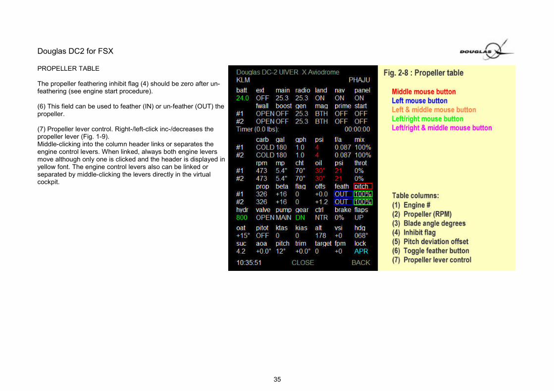
PROPELLER TABLE
The propeller feathering inhibit flag (4) should be zero after un-feathering (see engine start procedure).
(6) This field can be used to feather (IN) or un-feather (OUT) thepropeller.
(7) Propeller lever control. Right-/left-click inc-/decreases thepropeller lever (Fig. 1-9).Middle-clicking into the column header links or separates theengine control levers. When linked, always both engine leversmove although only one is clicked and the header is displayed inyellow font. The engine control levers also can be linked orseparated by middle-clicking the levers directly in the virtualcockpit.
35

Douglas DC2 for FSX
HYDRAULICS TABLE
(1) Hydraulic pressure is shown in red (below 650 psi), green(above 725 psi), and yellow (low pressure) color. The hydraulichand pump (Fig. 1-2) can be operated by left-clicking the field(one stroke) or middle-clicking (continuous pumping until clickedagain).
(2) Opens or closes the hydraulic shut-off valve (Fig. 1-3). Thevalve must be open all times except in emergency case when thehand pump is to be used. The valve position is displayed red ifeither the hand pump is currently operated and the valve is open,or the valve is closed although the hand pump is not in use.
(3) Toggles the hydraulic pump switch on the overhead panel(Fig. 1-1). Right-click to set switch from AUX to OFF and toMAIN, and use left mouse button to move switch down fromMAIN to OFF and to AUX. When set to MAIN, the hydraulic shut-off valve (Fig. 1.3) must be open. Position AUX turns on anauxiliary hydraulic pump only providing pressure for the wheelbrakes (see description of hydraulic system for more details).
(4) Gear position indicator reads DN (100% down) or UP (0%down). If a percentage value is displayed, the gear is currentlymoving or stuck in an intermediate position (ie. due to a hydraulicproblem). Red color indicates that gear is unsafe, while greenconfirms that both main wheels are down and locked (colorscorrespond to the gear indicator lights in the virtual cockpit).
(5) Position of the landing gear control handle. There are three positions UP, NTRL and DOWN. Left-clicking sets the handle from NTRL to DN or from UP to NTRL,while right-clicking moves the handle into the other direction. Red color indicates that the gear is down although airspeed is above the gear operation limit. However,since there is no Vle with this aircraft, the color will never change to red unless gear is operated above 204 KIAS (Vne). When the landing gear control lever isoperated using this mouse click area, the gear safety lock lever is automatically moved to the properposition, so that the pilot does not have to take care about. The same happens if the gear is operated using the keyboard command 'G' or triggered by a hardwareswitch (ie. a joystick button). When using keyboard commands or joystick for the gear, the landing gear control lever automatically moves to position NTRL after thegear has moved down or up.
(6) The header of this column reads "park" if the parking brake is set in, otherwise "brake" is visible. Left-clicking is applying brake pressure (indicated by apercentage value). A middle-click activates or releases the parking brake (Fig. 1-6). Red color indicates a brake failure (use either hand pump (Fig. 1-2) or set
36

Douglas DC2 for FSX
hydraulic switch (Fig. 1.1) to AUX).(7) The wing flap position can be shown as percentage (0%=up, 100%=down), deflection angle in degrees, or position (UP, P1, P2,DN). Middle-click column header to change the display unit. Left-click to increase flaps towards down position and right-clickfor decreasing. The flaps lever automatically moves to neutral position. Do not extend the flaps completely above 87 KIAS (Vfe). Red warning is given if flaps are notup above that airspeed limit.
SPEED TABLE
(1) Displays outside air temperature, barometer pressure, or anumber representing air density. Middle-ckicking the headerchanges between these three possibilities. The value is shown inred font, if air temperature is lower than -1°C (danger of icing).
(2) Turns pitot heater on or off. Red warning is given in case of apitot blockade with heater off (ie. causes failure of ASI).
(3) Shows true airspeed (TAS) in various units. Middle-clickcolumn header to choose, knots (KTAS), mach number,kilometers per hour (kph), and miles per hour (mph).
(4) Indicated airspeed (IAS) in knots. Color is yellow if Vno isexceeded, and red above Vne (see limits section).
(5) Altimeter (indicated altitude in feet)
(6) VSI (vertical speed in feet/min)
(7) Displays gyro heading degrees.
37

Douglas DC2 for FSX
AUTOPILOT TABLE
(1) Left-click toggles standby vacuum pump. With low suctionpressure, the display changes to red.
Field (4) shows elevator trim position in degrees. Left-clicking istrimming nose-down, and right-clicking nose-up.A middle-click zeros pitch trim.
(5) The target altitude is the altitude the autopilot will climb ordescent to if mode "ALT hold" is active. To select thedesired target altitude, left-/right-click to dec-/increase the value in100 feet steps. Middle-clicking the value activatesor deactivates the autopilot mode "ALT hold". If "ALT hold" isactive, the column header is displayed in green color.
Column (6) controls the vertical speed the autopilot is climbing ordescenting to the currently selected target altitude.Left-/right-click to dec-/increase the autopilot vertical speed.Middle-clicking the value causes following action: If the value isnot zero, the desired vertical speed is set 0. However, if the valueis already zero and the autopilot is completely turned off, theautopilot is turned on, holding current altitude and heading. Thecolumn header is displayed in green font, if autopilot mode "ALThold" is active.
(7) Select autopilot modes for automatic heading, navigation andapproach. Four different modes can be selected, which are "NAVhold" (fly towards a VOR station), "APR hold" (ILS approach with glide slope), "LOC hold" (ILS, localizer only), and the normal "HDG hold" (hold heading bugdegrees). To select a mode: Middle-click into header "lock" until the desired mode is displayed in blue font: "NAV", "APR", "LOC", or heading bug degrees(representing HDG mode). Then, while in blue font: Middle-click into the desired mode to select it as new active mode for the autopilot. When the selected mode hasmade active, the header ("lock") is displayed in green color. To turn off an active autopilot mode, middle-click into the field which is displaying the currently selected mode (the header "lock" should turn from green to white color, indicating that the selected mode is no longer active). If the currentlyselected mode is HDG, the desired autopilot heading course (heading bug degrees) can be set by left-/right-clicking into the field.
Example 1: How to activate the autopilot to hold current heading and altitude
Push autopilot button on the glareshield panel in the virtual cockpit. To do the same using the autopilot table on the control panel you must act as follows: Withautopilot turned off, middle-click vertical speed value (6). If that value is not zero, middle-click again (the first click zeros the value and the second activates the
38

Douglas DC2 for FSX
autopilot). Alternatively, you can enter the current altitude as new autopilot target altitude (5), and middle-click it. This activates "ALT hold".To activate "HDG hold" with the current course, click into header of column (7) until the autopilot heading bug degrees are displayed in the field below. There, enterthe current heading degrees as desired new autopilot heading using left-/right-clicking or mouse-wheel. Finally, middle-click both, header and value field of column(7): Middle-clicking "lock" makes the currently selected autopilot mode be displayed in blue font, and middle-clicking the blue heading degrees activates "HDG hold"with the desired course.
Example 2: How to make the autopilot flying towards a VOR-station
First, enter the NAV-frequency of the desired VOR-station on the NAV1-radio. When a signal is received, center the CDI-needle of the VOR1-indicator (with visible"TO"-flag). Then, middle-click "lock" (header column (7) on the autopilot table) until "NAV" is displayed in blue font in the field below. Middle-click into "NAV", while itis still shown in blue color, to make this mode active.
Example 3: How to let the autopilot fly an ILS approach
Begin with entering the correct ILS frequency on the NAV1 radio. Then, enter final runway course on the VOR1-indicator (rotate OBS1 knob until the VOR1-indicatorcompass rose aligns with final runway heading). Wait, until CDI-needle is beginning to move from one side to the other, indicating that the ILS-beam is intercepted.At this time, middle-click "lock" until "APR" is selected in the value field of column (7). While it is displayed in blue font, middle-click "APR" to make "APR hold" activeas new autopilot mode. The autopilot is calibrated in the way, that the aircraft is not climbing into the glide slope when flying below the GS-beam. In that case, theautopilot activates "ALT hold" until the glide slope is reached and then "GS hold" isautomatically activated.
If the runway ILS does not have a glide slope (localizer signal only), choose "LOC" instead of "APR" as mode. Then, use target altitude (5) and vertical speed (6) onthe autopilot table to let the autopilot control the altitude, or fly without "ALT hold" for manual altitude control.
39

Douglas DC2 for FSX
Possible issues with the Douglas DC2 for FSX:
1) Simconnect.
The SimConnect.xml file contains communication information for the SimConnect server. Normally it will not need to be changed, but the file should be placed in thein the <Drive>:\Documents and Settings\<alias>\Application Data\Microsoft\FSXfolder on the computer the server is running on. If you don't have a file named "SimConnect.xml" in that directory, place the file version shipped with the DC-2 into it(file is taken from the FSX SDK). If you already find a SimConnect.xml, do not overwrite it, as other add-ons may no longer work correctly. To work with the DC-2,the SimConnect.xml must include a "local" section:
<SimConnect.Comm> <Disabled>False</Disabled> <Protocol>Auto</Protocol> <Scope>local</Scope> <Address></Address> <MaxClients>64</MaxClients> <Port></Port> <MaxRecvSize>4096</MaxRecvSize> <DisableNagle>False</DisableNagle> </SimConnect.Comm>
If your SimConnect.xml does not have such a section, add the above to the file. If this file is missing or does not have a "local" section, you cannot change fuel andpayload weights by mouse-clicking into the trim sheet pop up.
2) Starter torque.
Some may experience trouble starting the engine. This can be caused by the Engine starter torque.Change the following in the AIRCRAFT.CFG:[piston_engine]normalized_starter_torque=0.3 // increase if engine rpm does not reach 375
3) Steering tail wheel.
When you want to steer on the ground “the easy way” (so not using differential throttle and brakes:Change the following in the AIRCRAFT.CFG:[contact_points]point.0 = 1, -32.763, 0, -1.40, 2974, 0, 0.8, 180, 0.3, 0.4, 0.9, 0, 0, 0, 0, 0//point.0 = 1, -32.763, 0, -1.4, 2974, 0, 0.8, 90, 0.3, 0.9, 0.8, 0, 0, 0, 0, 0 //changes to steerable TW.
40

Douglas DC2 for FSX
4) Ground Power
To have ground power available as intended in FSX+SP2 check below mentioned line in the aircraft.cfg:
max_battery_voltage = 24.0 // with FSX SP2 set = 28.2, with FSX Accel set = 24.0
The standard setting in the aircraft.cfg is for FSX Acceleration
5) Brake failure after engine start
If you are experiencing a brake failure after starting the engines, although sufficient hydraulic pressure is available, the problem may be caused by using an old flightsituation (FLT-file) which was created before this update package had been installed. To avoid this, we recommend to no longer use those old flight situations. Seebelow, how to create a cold & dark situation for your DC-2. Alternatively, if you have a flight situation which is producing the brake failure bug, you can edit thecorresponding FLT-file manually by hand and remove all those [SystemFailureX.0]sections you can find in it. Then, save the file, restart FSX and load the flight situation. The brakes should now be operative.
You can create a cold & dark situation following these steps:a) Start FSX with a default flight situation which is NOT the DC-2. Ideally, it is a FSX stock plane with RUNNING ENGINE(S), ie. A situation, like "Cessna on my home base".
b) Change to the desired airport/location and then load the DC-2 (still with running engines)
c) Choose "EMPTY" as fuel configuration on the trim sheet popup panel.
d) Save as your DC-2 cold&dark situation.
41