double adjustable shock absorbers! You can rest ... Coil Over Instructions... · Congratulations on...
10
Rev. 140424 1 Phone: 952-469-4130 www.vi-king.com Fax: 952-469-4132 21401 Hemlock Ave. Lakeville, MN 55044 Phone: 952-469-4130 www.vi-king.com Fax: 952-469-4132 Congratulations on your purchase of Viking Warrior TM double adjustable shock absorbers! You can rest assured that you are getting the best value for your dollar with Viking high performance shocks. *Note: It is strongly recommended that you purchase a spanner wrench and thrust bearing kit (part #7995-102) for ease of adjustment. INSTALLATION Please read these instructions carefully and entirely prior to installing your new Viking shocks. 1. Verify that your shocks are the correct lengths and mount style before beginning installation. Contact your chassis builder, supplier or Viking if you have any questions. 2. Measure your vehicle’s ride height by measuring from the center point of the fender lip down to the ground. Mark the spot you measured to for later reference. 3. Reference your vehicle’s owner’s manual to determine the proper jacking locations, and the instructions for removing the shocks and springs. FAILURE TO FOLLOW THE INSTRUCTIONS CAN RESULT IN SERIOUS INJURY OR DEATH. 4. Jack your vehicle up until the tires do not touch the ground and the suspension hangs freely and remove the wheels. Remove the shocks and sway bar mounts, if applicable, and retain all mounting hardware. 5. Important: Ensure that factory or replacement compression bumpers are in place and in good condition prior to installing the shocks. Also check other components on the chassis such as bushings, ball joints, etc. and replace if needed. 6. Use a floor jack to support the lower control arm and remove the cotter pin and ball joint nut from the lower ball joint. Loosen the ball joint stud from the spindle using a tie rod / ball joint separator. Carefully and slowly release the lower control arm assembly by lowering the floor jack until the spring can be safely removed. 7. Remove the hardware that retained the stock shock in the lower control arm. Clean the mounting bolt holes thoroughly. You may need to slightly open them using a file or 3/8” drill bit. 8. Important: Verify the shock body will clear the spring pocket sheet metal. These tolerances varied greatly out of the factory, and this pocket may need to be opened up to allow adequate clearance for the shock body. 9. Install one stud washer and one bushing (half of the shock stud bushing pack) onto the stud. 10. Fully extend the piston rod. 11. Screw the lock nut (shoulder up) and the spring nut (shoulder up) down to the last thread only (See figure on the right). INSTALLATION / TUNING GUIDE FOR VIKING WARRIOR DOUBLE ADJUSTABLE GM / MUSTANG II KITS [Part Numbers Beginning A201 – A2xx]
Transcript of double adjustable shock absorbers! You can rest ... Coil Over Instructions... · Congratulations on...
Rev. 140424
1 Phone: 952-469-4130 www.vi-king.com Fax: 952-469-4132
21401 Hemlock Ave. Lakeville, MN 55044 Phone: 952-469-4130 www.vi-king.com Fax: 952-469-4132
Congratulations on your purchase of Viking WarriorTM double adjustable shock absorbers! You can rest assured that you are getting the best value for your dollar with Viking high performance shocks.
\
*Note: It is strongly recommended that you purchase a spanner wrench and thrust bearing kit (part #7995-102) for ease of adjustment.
INSTALLATION Please read these instructions carefully and entirely prior to installing your new Viking shocks. 1. Verify that your shocks are the correct lengths and mount style before beginning installation.
Contact your chassis builder, supplier or Viking if you have any questions. 2. Measure your vehicle’s ride height by measuring from the center point of the fender lip down to
the ground. Mark the spot you measured to for later reference. 3. Reference your vehicle’s owner’s manual to determine the proper jacking locations, and the
instructions for removing the shocks and springs. FAILURE TO FOLLOW THE INSTRUCTIONS CAN RESULT IN SERIOUS INJURY OR DEATH.
4. Jack your vehicle up until the tires do not touch the ground and the suspension hangs freely and remove the wheels. Remove the shocks and sway bar mounts, if applicable, and retain all mounting hardware.
5. Important: Ensure that factory or replacement compression bumpers are in place and in good condition prior to installing the shocks. Also check other components on the chassis such as bushings, ball joints, etc. and replace if needed.
6. Use a floor jack to support the lower control arm and remove the cotter pin and ball joint nut from the lower ball joint. Loosen the ball joint stud from the spindle using a tie rod / ball joint separator. Carefully and slowly release the lower control arm assembly by lowering the floor jack until the spring can be safely removed.
7. Remove the hardware that retained the stock shock in the lower control arm. Clean the mounting bolt holes thoroughly. You may need to slightly open them using a file or 3/8” drill bit.
8. Important: Verify the shock body will clear the spring pocket sheet metal. These tolerances varied greatly out of the factory, and this pocket may need to be opened up to allow adequate clearance for the shock body.
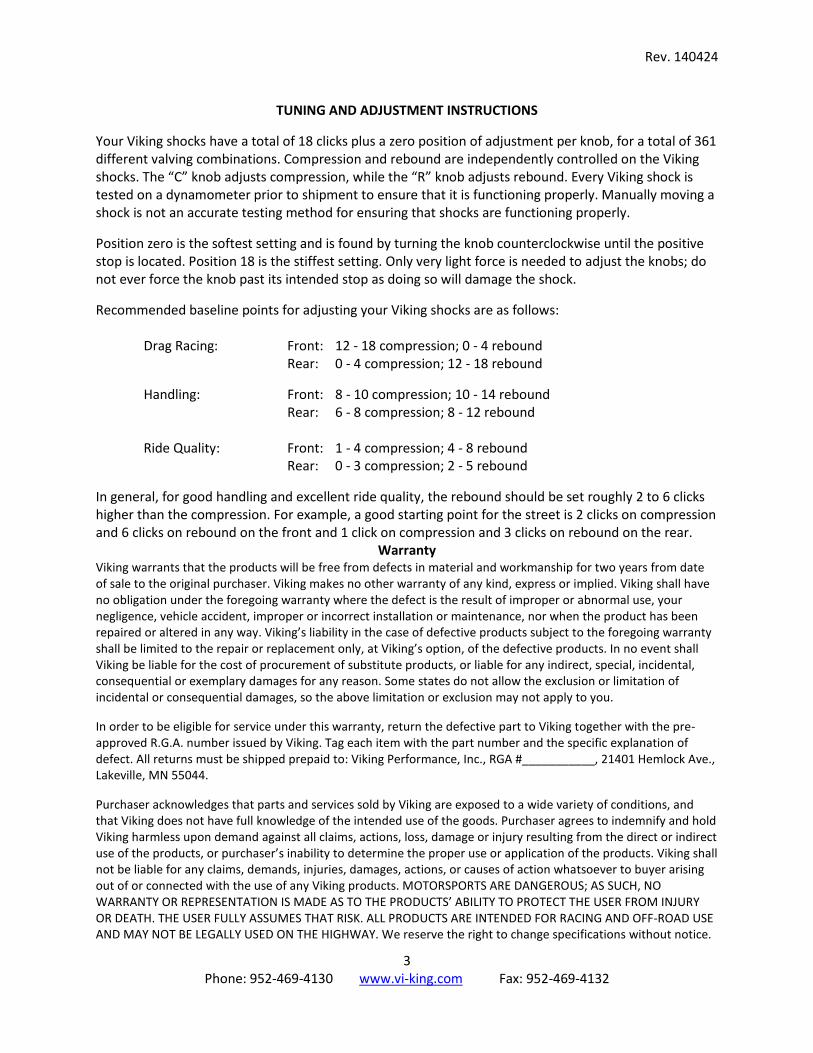
9. Install one stud washer and one bushing (half of the shock stud bushing pack) onto the stud. 10. Fully extend the piston rod. 11. Screw the lock nut (shoulder up) and the spring nut (shoulder up) down to the last thread only
(See figure on the right).
INSTALLATION / TUNING GUIDE FOR VIKING WARRIOR DOUBLE ADJUSTABLE
GM / MUSTANG II KITS [Part Numbers Beginning A201 – A2xx]
mark
Typewriter
NOTE: Kits may contain Viking or QA1 Shocks.
mark
Typewriter
mark
Typewriter
mark
Typewriter
mark
Typewriter
mark
Typewriter
mark
Typewriter
Rev. 140424
2 Phone: 952-469-4130 www.vi-king.com Fax: 952-469-4132
12. Apply anti-seize to the threads on the nuts and the shock. If the Viking thrust bearing kit is used
(recommended), coat both washers with anti-seize. Install the spring seat washer, then the bearing, then the second washer. If you do not use the thrust bearing kit, then coat one side of the washer supplied with the shock with anti-seize and place it coated side down on the spring nut. THE WARRANTY IS VOID AND DOES NOT COVER DAMAGE TO THE SHOCK RESULTING FROM THE FAILURE TO APPLY ANTI-SEIZE PRIOR TO MAKING RIDE HEIGHT ADJUSTMENTS.
13. Install the spring onto the shock, putting the small end of the spring over the shock body and down onto the spring seat.
14. For GM Kits: Install the shock with the T-bar on top of the lower control arm with the adjustment knobs facing out toward the spindle utilizing the 3/8” bolts and nylock nuts. Before tightening, ensure that the shock is centered in the lower control arm.
15. For Mustang II Kits: If necessary, drill out the lower control arm bolt holes to the appropriate size depending on the shock style selected. If applicable, insert the bearing in a twisting motion. It may be necessary to press the bearings into the shock. If so, do not press on the ball; press only on the race surrounding the ball. Install snap rings on both sides of each bearing and ensure they are fully seated in the loops.
16. Jack the control arm up very slowly until the shock stud extends through the factory mount while vertically rotating the assembly and making sure that the shock is not binding. You may need to also rotate the spring until it is properly located in the factory recesses.
17. Install the upper stud bushing, washer and nut. 18. Reassemble the lower a-arm and the spindle. Torque the spindle nut to factory specifications
and insert the cotter pin. 19. Adjust the spring nut up about 1/3 of the way from the bottom of the threads on the shock. 20. Reattach the wheels and torque everything to the specifications defined by the vehicle’s
manufacturer. 21. Verify that there is clearance around the coil-over shock and that the suspension does not bind
at all, even when wheels are turned to full lock position. 22. Carefully place the car on the ground to check clearances again. Lightly bounce the vehicle at
each corner to verify that there are not any clearance issues. 23. Measure the ride height as you did prior to installation and ensure that there is sufficient travel
in both directions. Ideally, 60% of the shock stroke is available for compression. Adjust the ride height only with the weight of the vehicle fully off of the tires. THE WARRANTY IS VOID AND DOES NOT COVER DAMAGE TO THE SHOCK DUE TO INCORRECT RIDE HEIGHT OR BY MAKING RIDE HEIGHT ADJUSTMENTS WITHOUT THE TIRES RAISED OFF THE GROUND. Raise or lower the ride height by adjusting the spring nut to achieve the desired ride height. If it is at the extreme top or bottom of the threads, then you may need a softer or heavier spring.
24. Once ride height is correct, spin the lock nut up to the bottom of the spring nut and lock them together using the two spanner wrenches.
25. It is important to note that your shocks should never be used as a travel limiter. Straps or cables made for travel limitation should be used prevent topping out. Vehicles used in a manner where they could bottom out the shocks (such as drag racing) should use a higher rate spring and a bump stop to help prevent shock damage. Any shock can be damaged from wheel stands despite bump stops.
26. Have your front end realigned upon completion of installation.
Rev. 140424
3 Phone: 952-469-4130 www.vi-king.com Fax: 952-469-4132
TUNING AND ADJUSTMENT INSTRUCTIONS Your Viking shocks have a total of 18 clicks plus a zero position of adjustment per knob, for a total of 361 different valving combinations. Compression and rebound are independently controlled on the Viking shocks. The “C” knob adjusts compression, while the “R” knob adjusts rebound. Every Viking shock is tested on a dynamometer prior to shipment to ensure that it is functioning properly. Manually moving a shock is not an accurate testing method for ensuring that shocks are functioning properly. Position zero is the softest setting and is found by turning the knob counterclockwise until the positive stop is located. Position 18 is the stiffest setting. Only very light force is needed to adjust the knobs; do not ever force the knob past its intended stop as doing so will damage the shock. Recommended baseline points for adjusting your Viking shocks are as follows:
Drag Racing: Front: 12 - 18 compression; 0 - 4 rebound Rear: 0 - 4 compression; 12 - 18 rebound
Handling: Front: 8 - 10 compression; 10 - 14 rebound Rear: 6 - 8 compression; 8 - 12 rebound Ride Quality: Front: 1 - 4 compression; 4 - 8 rebound Rear: 0 - 3 compression; 2 - 5 rebound
In general, for good handling and excellent ride quality, the rebound should be set roughly 2 to 6 clicks higher than the compression. For example, a good starting point for the street is 2 clicks on compression and 6 clicks on rebound on the front and 1 click on compression and 3 clicks on rebound on the rear.
Warranty Viking warrants that the products will be free from defects in material and workmanship for two years from date of sale to the original purchaser. Viking makes no other warranty of any kind, express or implied. Viking shall have no obligation under the foregoing warranty where the defect is the result of improper or abnormal use, your negligence, vehicle accident, improper or incorrect installation or maintenance, nor when the product has been repaired or altered in any way. Viking’s liability in the case of defective products subject to the foregoing warranty shall be limited to the repair or replacement only, at Viking’s option, of the defective products. In no event shall Viking be liable for the cost of procurement of substitute products, or liable for any indirect, special, incidental, consequential or exemplary damages for any reason. Some states do not allow the exclusion or limitation of incidental or consequential damages, so the above limitation or exclusion may not apply to you. In order to be eligible for service under this warranty, return the defective part to Viking together with the pre-approved R.G.A. number issued by Viking. Tag each item with the part number and the specific explanation of defect. All returns must be shipped prepaid to: Viking Performance, Inc., RGA #___________, 21401 Hemlock Ave., Lakeville, MN 55044. Purchaser acknowledges that parts and services sold by Viking are exposed to a wide variety of conditions, and that Viking does not have full knowledge of the intended use of the goods. Purchaser agrees to indemnify and hold Viking harmless upon demand against all claims, actions, loss, damage or injury resulting from the direct or indirect use of the products, or purchaser’s inability to determine the proper use or application of the products. Viking shall not be liable for any claims, demands, injuries, damages, actions, or causes of action whatsoever to buyer arising out of or connected with the use of any Viking products. MOTORSPORTS ARE DANGEROUS; AS SUCH, NO WARRANTY OR REPRESENTATION IS MADE AS TO THE PRODUCTS’ ABILITY TO PROTECT THE USER FROM INJURY OR DEATH. THE USER FULLY ASSUMES THAT RISK. ALL PRODUCTS ARE INTENDED FOR RACING AND OFF-ROAD USE AND MAY NOT BE LEGALLY USED ON THE HIGHWAY. We reserve the right to change specifications without notice.
Rev. 140424
4 Phone: 952-469-4130 www.vi-king.com Fax: 952-469-4132
OTHER PRODUCTS FROM VIKING
Coil-Over Springs - Made in the U.S.A. - Ultra-lightweight, high travel springs engineered with an expanded body diameter for
unsurpassed performance. Up to a 25% weight savings over some other springs in the market!
- High tensile spring steel with a sleek silver powder coat finish as standard; Mustang II springs are chrome plated
- Cold wound, heat treated and shot peened; ground at both ends; manufactured to precision tolerances
- 4" - 14" free lengths available in a wide variety of rates - Lengths and rates clearly marked on springs - Lifetime guaranteed to remain within 2% of the original free height and rate - Viking prices its springs based on actual material used, which equals lower cost for many of
the most popular springs Rod End & Spherical Bearings
- Same day shipment! - Huge selection of styles, materials and sizes
o Sizes 3/16” – 1” stocked as standard, larger sizes available upon request o Aluminum and stainless, chromoly and carbon steel bearings stocked as standard o Injection molded loaded slot and two-piece stocked as standard; other styles
available special order - 2 year materials and workmanship warranty
Adjusters, Clevises, Solid Rod Eyes, Jam Nuts
- Stocked as standard - Wide variety of sizes available
Now Available Viking’s patent pending CrusaderTM shocks are now available! These shocks feature interchangeable needles and seats to allow fine tuning of the rebound adjustment range without disassembling the shocks – no special tools required. These shocks are capable of generating very soft rebound for the ultimate comfort ride or extremely high progressive rebound forces that are ideal for 750+ hp drag vehicles and small tire, drag radial applications. Follow Viking on Facebook at: www.facebook.com/vikingperformance to get the most up-to-date product releases first! At Viking, we are all about providing exceptional customer service. We will always strive to keep you more than satisfied by delivering great quality parts on time and at the best value.
Thank you for your business!

Rev. 05/09/06
MOTORSPORTS
Technical Support Line: (952) 985-5675Fax Line: (952) 985-5679
ASSEMBLY INSTRUCTIONSREAD ALL INSTRUCTIONS CAREFULLY AND THOROUGHLY PRIOR TO STARTING
INSTALLATION. PRODUCTS THAT HAVE BEEN INSTALLED ARE NOT ELIGlBLE FOR RETURN.SEE YOUR CAR'S OWNER'S MANUAL FOR PROPER JACKING LOCATIONS AND SHOCKISPRING
REMOVAL TECHNIQUES. DEATil OR SERIOUS INJURY CAN RESULT IF INSTRUCTIONS ARENOT CORRECTLY FOLLOWED. A GOOD CHASSIS MANUAL, AVAILABLE AT YOUR LOCAI.
PARTS STORE, MAY ALSO AlD IN YOUR INSTALLATION.
Proma Star (DR, DDR)Ultra Ride* (UR)
Aluma Matic" (ALN)Stocker Star* (TC, DTC, MU, DMU)
Stocker Star*"R" Series (RC)
• DISCLAIMER / WARRANTY •
QAl warrants that the products will be free from defëets in material and workmanship for one year from date of saleto the original purchaser. QAl makes no other warranty of any kind, express or implied. OAl shall have noobligation under the foregoing warranty where the defect is the result of improper or abnormal use, your negligence,vehicle accident, improper or incorrect installation or maintenance, nor when the product has been repaired oraltered in any way. QAl's liability in the case of defective products subject to the foregoing warranty shall belimited to the repair or replacement, at QA I 's option, of the defective products.
The user understands and recognizes that racing parts, specialized street rod equipment, and all parts andservices sold by QAl are exposed to many and varied conditions due to the manner in which they areinstalled and used. QAl shall bear no liability for any loss, damage or injury, either to a person or toproperty, resulting from the installation, direct or indirect use of any QAI products or inability by the buyerto determine proper use or application of QAI products. With the exception of the limited liability warrantyset forth ahove, QAl SHALL NOT BE LIABLE FOR ANY CLAIMS, DEMANDS, INJURIES, DAMAGES,ACTIONS, OR CAUSES OF ACTION WHATSOEVER TO BUYER ARISlNG OUT OF OR CONNECTEDWITH THE USE OF ANY QAl PRODUCTS.
MOTORSPORTS ARE DANGEROUS; AS SUCH, NO WARRANTY OR REPRESENTATION IS MADEAS TO THE PRODUCT'S ABILITY TO PROTECT THE USER FROM INJURY OR DEATH. THE USERASSUMES TIIAT RISK.

Rev. 08/08/05
• INSTRUCTIONS • PROMA STAR* / ULTRA RIDE / AL UMA MATIC*• INSTRUCTIONS •
To maintain the integrity of the product, it is recommended that the shock be installed at the specific ride height for each modelsize to protect the piston and valve assembly from possibly topping or bottoming out.
SHOCK PART # RECOMMENDED RECOMMENDED RECOMMENDED APPLICAT1ONRIDE HEIGHT SPRING LENGTH
(FREE I ENGTH)ALN -3855 9 ¾" 10 34" T FRONTALN -4855 12" 12 ½" 9", 10" FRONT / REARALN -5855 13 ½" 14" 12 ' REARDR / DDR -3855 9 ½· 10 ' T' FRONTDR/DDR -3955 10¾" 11 " 7",8",9" FRONTDR / DDR -4855 11 ½ - l2 · 9", 10" FRONT / REARDR / DDR -5855 13 ¼ - 14 ' 12" REARDR / DDR -7855 L5 ¼" 15 " 14" REARDR / DDR -8855 16" - 16¾" 14" REARDR / DDR -9855 18 ½" 19 ½" 14" REARUR -3855 9 ¾" - 10 ¼" 7" FRONTUR -3955 10 ¾" 11 ¼" 7", 8".9" FRONTUR -4855 11 ¾" 12 "
9", 10" FRONT / REARUK -5855 i3¾"-i44" 12' REARUR -7855 15 ¼" 15 ¼" 14" REAR
• Clamp the lower mounting loop in a large vise. Use of soft jaws is recommended to protect the aluminum housing fromscratches, etc.
• Screw the aluminum lock nut (shoulder up) and the spring seat adjuster nut (shoulder up) down to the last thread - NOFURTEIER. Now is a good time to lubricate the threads ofthe shock body with an anti-seize lubricant. Pull the piston rodall the way out. Check the jam nut under the upper bearing housing making sure it is secure.
• Coat one side of the stainless steel spring seat washer with anti-seize lubricant. Place the lubricated side of the washer downon the spring seat. Slide the spring over the shock body and down onto the spring scat, Slip the spring cap in place, makingsure that it is set in the spring squarely. The spring rate and length selectcd for your application will determine how difficultthey will be to install.
• Adjust the spring scat up until the spring is slightly compressed. This ensures that the spring cap, spring and spring seatwasher remain in place and aligned. Make sure that the spring cap is aligned properly under the upper bearing mount.
• For poly bushing mounted shocks, insert the proper bushings into your poly mount and repeat for the other assembly,• For bearing mounted shocks, test fit the bearings in both ends of the shock - bearings may move easier on one side than the
other. Assemble by inserting the bearing in a twisting motion. Install snap rings on both sides of the bearing. In some casesit may be necessary to press the bearings into the mount. Repeat for the other assembly.
• Bolt both assemblies onto the car. Place the car on the ground and check the shock ride height measurements. Shock rideheight is the distance from the center of the top mounting loop to the center of the bottom mounting loop. Make sure thatthe measurement is taken with the car weighted as it would be race ready. Compare this measurement to the recommendedride height listed for your part number in the chart above. Raise or lower the spring seat to obtain the required ride height.If you have selected the proper spring rate, your spring seat should be approximately in the center to 1/3 from the bottom ofthe threaded area of the shock. If the spring seat is at either the extreme top or bottom of the threads, the purchase of a softeror stiffer spring may be required. Now spin the jamnut up to the bottom of the spring seat and lock them together.
• If the car sits higher or lower than desired. unbolt the adiustable shock mount brackets and move the car up or down to getthe car ride height you are looking to achieve.
• See back page for diagrams and technical assistance.
•PROMA STAR*/ ULTRA RIDE*e VALVING ADJUSTMENT•• QAl shocks have 12 damping settings (24 settings for double adjustables). Them are 4 clicks per revolution of the knob (8
for double adjustables). The knob has 3 complete revolutions. The knob set fully counter clockwise is the softest setting -
start your adjusting from that point. Recommended base settings to begin testing with are as follows:• For Proma Star* rear drag racing shocks, 3-5 clicks for foot brake and 4-7 clicks for trans brake racing;. For Proma Star* front shocks. 0-3 clicks for foot brake and 2-5 clicks for trans brake racing; and,• For Ultra Ridc* shocks, 2-5 clicks for the front, and 3-6 clicks for the rear.
NOTE: DO NOT FORCE THE ADJUSTER KNOB. DO NOT USE PLIERS OR ANY OTHER TOOLS ON THEPISTON ROD OR THE ADJUSTER KNOB. DO NOT EXCEED 12 CLICKS UNDER ANY CIRCUMSTANCES (24CLICKS FOR DOUBLE ADJUSTABLES). THIS COULD DAMAGE THE IDLER PIN AND CAUSE THE SHOCKNOT TO ADJUST. THIS WILL VOID ALL WARRANTIES. DO NOT USE THE SHOCK ABSORBER AS A DROOPLIMITER. SEVERE DAMAGE TO THE SHOCK COULD OCCUR AND VOID ALL WARRANTIES.
2

Rev. 08/08/05
• INSTRUCTIONS• STOCKER STAR*/ STOCKER STAR*"R" SERIES•INSTRUCTIONS•See the back page for diagrams and technical assistance.
FRONT SHOCKS.• Before installing your new Stocker Stars", make sure that the original compression bumpers (control arm & frame) are in
place and in good condition. [f they have been removed or damaged they must be replaced before you continue with thisinstallation. If the shocks are installed without the factory bumpers or equivalent, damage to the shocks may resultand will void all warranties.
• Begin by checking to see if the Stocker Star wm fit through the lower control arm without modification. OM recommendsdropping the control arm to install the shock to avoid modifying the control arm. This requires separating the ball joint studfrom the spindle.
• See your car's owner's manual for proper jacking locations and shock/spring removal techniques. Death or seriousinjury can result if instructions are not correctly followed.
. Start by jackingthe car up with a floor jack under the lower control arm the car should be high enough to put a jack standunder the chassis. Rcmove the existing shock. With the floor jack under the control arm, remove the cotter pin from thelower ball joint, then loosen the nut on the ball joint.
. The floor jack should be positioned so it will not slip offthe control arm. Split the ball joint with a tie rod wedge and slowlylower the jack. Slowly, CAREFULLY, Ict the A-arm assembly down until the spring is free and can be removed,
e To install the Stocker Star*. put the t-bar end of the shock through the hole in the control arm and install the 2 bolts on the t-bar do not lighten fully at this point. Slide the coil spring over the shock and align the bottom properly in the control arm.Move assembly up into the spring pocket in the frame. Align the spring up in the spring bucket and align the upper shockmount. Slowly jack the control arm up making sure not to bind the shock as the spring is compressed. lnsert ball joint studimo spindle and reinstall the nut. Torque the ball joint stud to the factorv spets and reinsert the cotter pin. Next, tighten thetwo shock bolts in the control arm.
• Check the ride height ofthe shocks and make sure there is adequate travel in both directions. Repeat the completeprocedure for the other side. A good rule of thumb 60% of the stroke should be used for compression. If the ride height isnot correct, damage may result and will not be covered under warranty.
REAR SHOCKS:• See your car's owner's manual for proper jacking locations and shock/spring removal techniques. Death or serious
injury can result if instructions are not correctly followed.• Begin by jacking the rear of the car up with a suitable floor jack. Place jack stands under the frame before continuing.
Remove the old pair of shocks using the floor jack to support the rear end housing. Retain the hardware as it may be usedfor reinstallation.
• Start the reinstallation by mounting the upper portion first. Depending on the application there should be littic or nomodifications necessary. Next, mount the lower portion of the shock to the rear end housing. Again there should be little orno modifications necessary.
. After a quick double check of the mounting hardware, making sure everything is secure, jack the rear end housing back upinto the chassis, if the rear end housing has been lowered far enough to release the springs, make sure they are realigned asthe housing isjackedback into place.
. Set car back on the ground,
. Because of deviations in ride heights from the factory specs, check to make sure that there is sufficient travel for bothextension and compression in the shoek. A good rule of thumb is that 60% of the stroke should be available forcompression. If the ride height is not correct, damage may result and will not be covered under warranty.
•STOCKER STAR*/ STOCKER STAR*"R" SERIES• VALVING ADJUSTMENT e
• Stocker Stars have 12 damping settings (24 settings for double adjustables). There are 4 clicks per revolution of the knob(8 clicks for double adjustables). The knob has 3 complete revolutions. The knob set filily counter clockwise is the softestsetting - start your adjusting from that point. Do not adjust past the 12th click (24 for double adjustables) or 3 revolutionsfrom the softest setting.
• The correct valve setting for your application is up to you. There are too many variables to recommend a specific setting foreach type of vehicle.
NOTE: DO NOT FORCE THE ADJUSTER KNOB. DO NOT USE PLIERSOR ANY OTHER TOOLSONTHE PISTON ROD OR THE ADJUSTER KNOB. DO NOT EXCEED 12 CLICKS UNDER ANYCIRCUMSTANCES (24 CLICKS FOR DOUBLE ADJUSTABLES). THIS COULD DAMAGE THE IDLERPIN AND CAUSE THE SHOCK NOT TO ADJUST. THIS WILL VOID ALL WARRANTIES.
3
Rev. 08/08/05
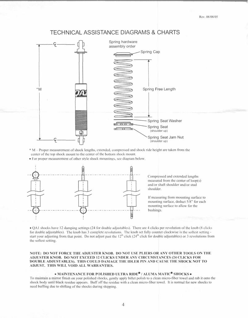
TECHNICAL ASSISTANCE DIAGRAMS& CHARTSSpring hardwareassembly order
.. Spring Cap
*M Spring Free Length
Spring Seat Washernrir,rrrir-h...
,a ..Spring Seat
(shoulder up)
C Spring Seat Jam NutL (shoulder up)
* M Proper measurement of shock lengths.extended, compressed and shock ride height are taken from thecenter of the top shock mount to the center of the bottom shock mount.
• For proper measurement of other style shock mountings, see diagram below.
Compressed and extended lengthsmeasured from the center of loop(s)and/or shaft shoulder and/or studshoulder.
If measurmg from mounting surface tomounting surface, deduct 5/8" for eachmounting surface to allow for the
-- ---------------- ---------------- - -- bushings.
•QA I shocks have 12 damping settings (24 for double adjustables), There are 4 clicks per revolution of the knob (8 elicksfor double adjustables). The knob has 3 completc revolutions. The knob set fully counter clockwise is the sollest setting -
start your adjusting from that point. Do not adjust past the 12 click (24*click for double adjustables) or 3 revolutions fromthe softest setting.
NOTE: DO NOT FORCE THE ADJUSTER KNOB. DO NOT USE PLIERS OR ANY OTHER TOOLS ON THEADJUSTER KNOB. DO NOT EXCEED 11 CLICKS UNDER ANY CIRCUMSTANCES (24 CLICKS FORÐOUBLE ADJUSTABLES). THIS COULD DAMAGE THE IDLER PIN AND CAUSE THE SHOCK NOT TOADJUST. THIS WILL VOID ALL WARRANTIES.
•MAINTENANCE FOR POLISHED ULTRA RIDE*/ ALUMA MATIC*SHOCKS•To maintain a mirror finish on your polished shocks, gently apply billet polish to a clean micro-fiber towel and rub it onto theshock body until black residue appears. Buff off the residue with a clean micro-tiber towel. It is normal for new shocks toneed buffing due to shifting of the shocks during shipping.
4
Doc #780-65531
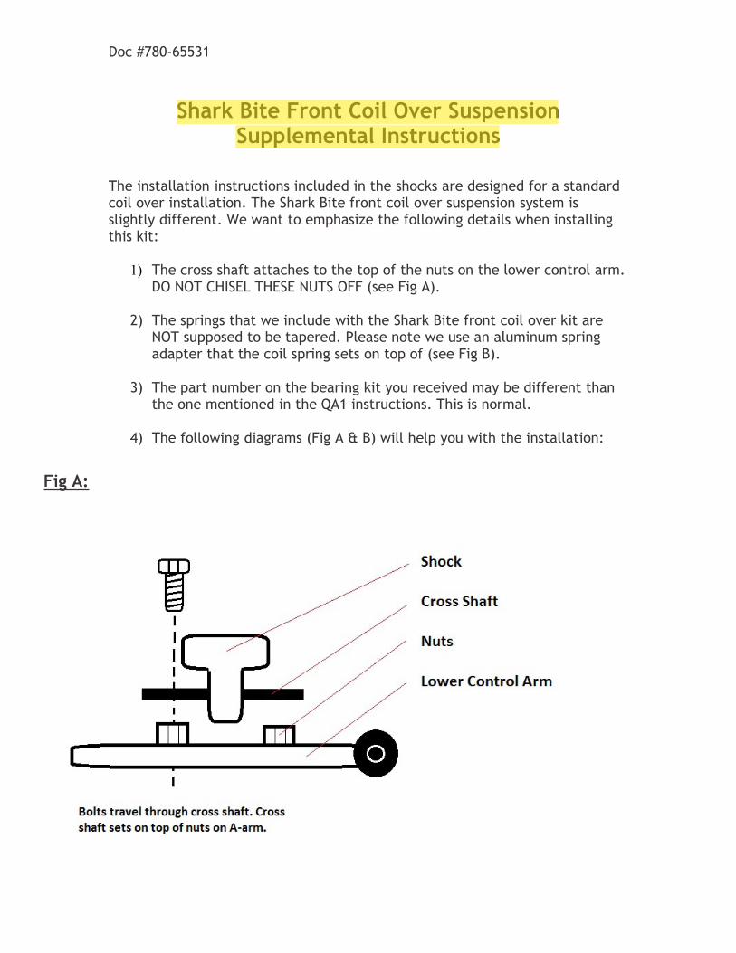
Shark Bite Front Coil Over SuspensionSupplemental Instructions
The installation instructions included in the shocks are designed for a standard coil over installation. The Shark Bite front coil over suspension system is slightly different. We want to emphasize the following details when installing this kit:
1) The cross shaft attaches to the top of the nuts on the lower control arm. DO NOT CHISEL THESE NUTS OFF (see Fig A).
2) The springs that we include with the Shark Bite front coil over kit are NOT supposed to be tapered. Please note we use an aluminum spring adapter that the coil spring sets on top of (see Fig B).
3) The part number on the bearing kit you received may be different than the one mentioned in the QA1 instructions. This is normal.
4) The following diagrams (Fig A & B) will help you with the installation:
Fig A:
mark
Highlight
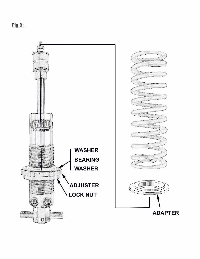
Fig B: