Boundary element analysis of stress intensity factor K in ...

' •
DOT/FAA/CT-93/68
FAA Technical Center Atlantic City International Airport, N.J. 08405
Stress-Intensity Factor Solutions for nk Rivet
February 1994
Final Report
t~ U.S. Department of Transportation Federal Aviation Administration
Tension

filiii 00015182
DOT/FAA ICT-93/ 68 C.2
Tan, P.w. Stress intensity factor solutions for cracks at countersunk rivet
j under the sponsorship Jrtation in the interest ted States Government ents or use thereof.
does not endorse products acturers' names appear ~sidered essential to the
1. Report No. 2. Go•••--• Accauion No.
DOT/FAA/CT-93/68 4. Title oncl Subtitle
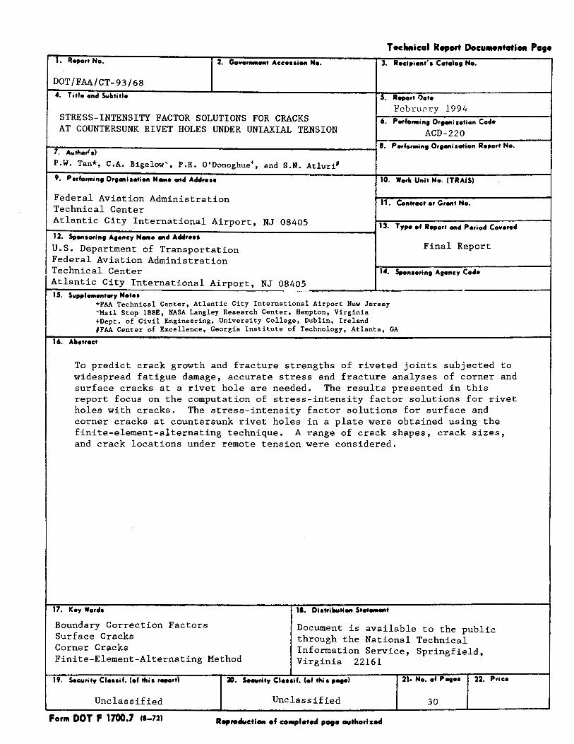
STRESS-INTENSITY FACTOR SOLUTIONS FOR CRACKS AT COUNTERSUNK RIVET HOLES UNDER UNIAXIAL TENSION
Technical Meport Docu!Hntation Page
3. Recipient' • Catalog No.
5. Report l)oto
Februnry 1994
6. Porfo1111ing Orgonilotion Coda
ACD-220
~r7":'::L:":;:;~----------------------------11. PerforMing Organization Report No. 1 7. Autftor' s)
P.W. Tan*, C.A. Bigelow', P.E. O'Donoghue+, and S.N. Atluri'
9. Performing Organization N-o ancl Acldrau 10. Worlc Unit No. (TRAIS)
Federal Aviation Administration Technical Center
11. Contract or Grant No.
Atlantic City International Airport, NJ 08405 t--;~-:----:--:----:-:----:-~:--------------------1 13. Typo of Report oncl Period Co•orocl
12. Sponsoring Ago,.cy N-• and Aclclrau
U.S. Department of Transportation Final Report Federal Aviation Administration Technical Center 1~. Sponsoring Agency Coda
Atlantic City International Airport, NJ 08405 15. Suppl-ontory Notes
*FAA Technical Center, Atlantic City International Airport New Jersey 'Mail Stop 188E, NASA Langley Research Center, Hampton, Virginia +Dept. of Civil Engineering, University College, Dublin, Ireland #FAA Center of Excellence, Georgia Institute of Technology, Atlanta, GA
16. Abstract
To predict crack growth and fracture strengths of riveted joints subjected to widespread fatigue damage, accurate stress and fracture analyses of corner and surface cracks at a rivet hole are needed. The results presented in this report focus on the computation of stress-intensity factor solutions for rivet holes with cracks. The stress-intensity factor solutions for surface and corner cracks at countersunk rivet holes in a plate were obtained using the finite-element-alternating technique. A range of crack shapes, crack sizes, and crack locations under remote tension were considered.
17. ICoy Worcls
Boundary Correction Factors Surface Cracks Corner Cracks Finite-Element-Alternating Method
11. Ols~illutiOfl Stot--t
Document is available to the public through the National Technical Information Service, Springfield, Virginia 22161
19. Security Clouif. (of tftis report) 211. Security Clouif. (of thi • pogo) 21. No. of Pogo• 22. Price
Unclassified Unclassified 30
Form DOT F 1700.7 Ct-72) Reprocluctlott of co111plotofl pogo authorlaofl

EXECUTIVE SUMMARY
INTRODUCTION
Table of Contents
FINITE-ELEMENT -ALTERNATING METHOD
CONFIGURATIONS AND LOADING
STRESS-INTENSITY FACTOR
RESULTS AND DISCUSSION
CONCLUDING REMARKS
REFERENCES
iii
Vll
1
2
3
3
4
5
6
Figure
1
2
3
4(a)
4(b)
5
6
7
8
9
10
11
12
13
LIST OF ILLUSTRATIONS
Page
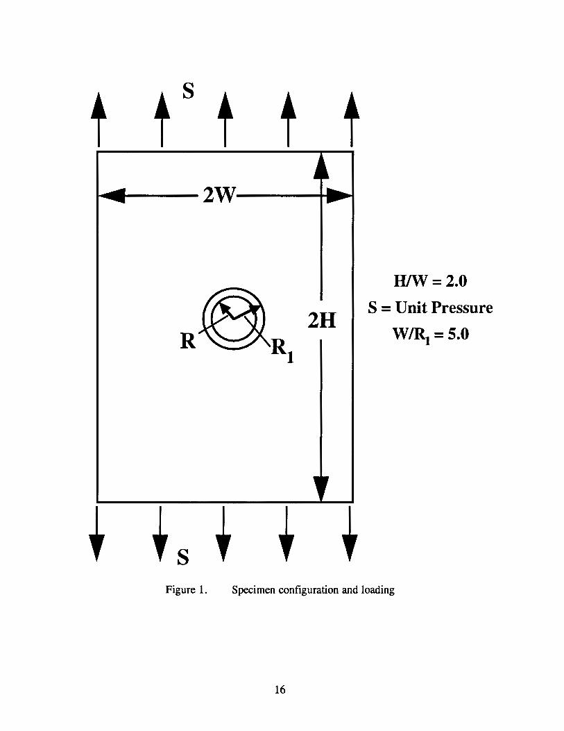
Specimen configuration and loading 16
Crack shapes and locations for countersunk hole; R/t = 2.0; h/t = 0.5; 8 = 50°; ale = 0.4, 0.7, and 2.0; aft = 0.2, 0.3 and 0.4 17
Typical convergence study results, crack location 3, aft = 0.2 and ale = 0.4
Plan view of a typical finite-element mesh, 496 elements and 2655 nodes
Detailed view of finite-element mesh at crack location
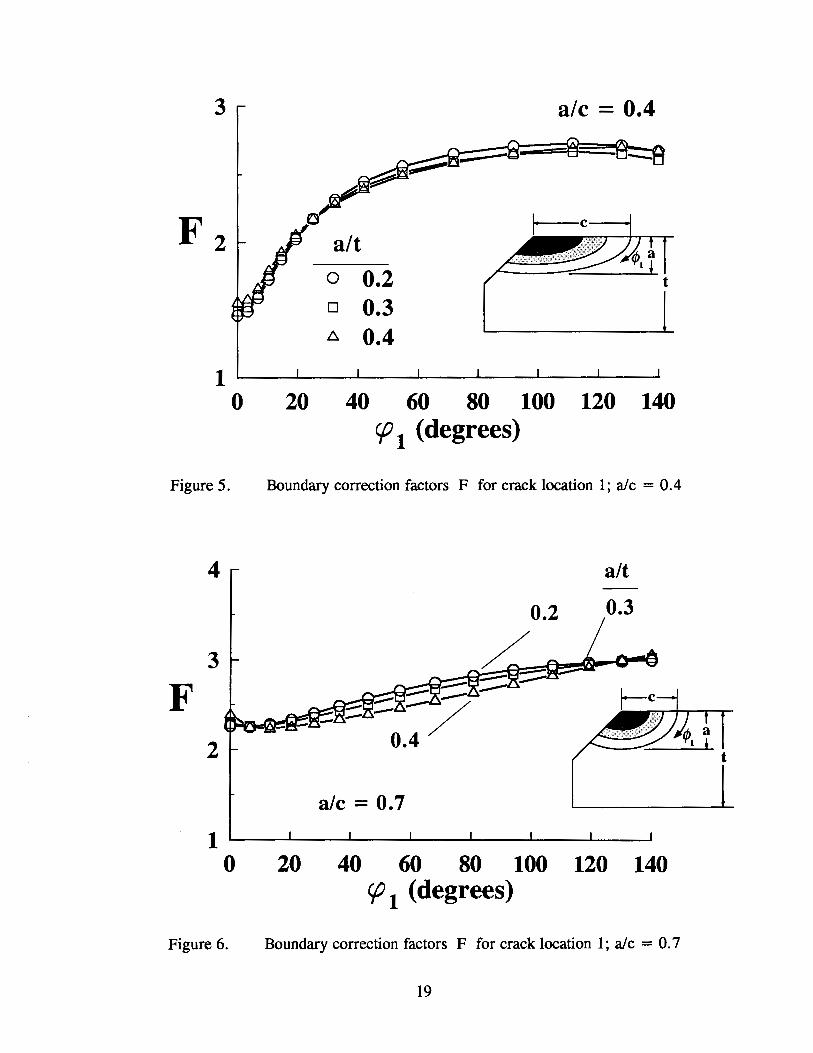
Boundary correction factors F for crack location 1; ale = 0.4
Boundary correction factors F for crack location 1; ale = 0. 7
Boundary correction factors F for crack location 1; ale = 2.0
Boundary correction factors F for crack location 2; ale = 0.4
Boundary correction factors F for crack location 2; ale = 0. 7
Boundary correction factors F for crack location 2; ale = 2.0
Boundary correction factors F for crack location 3; ale = 0.4
Boundary correction factors F for crack location 3; ale = 0. 7
Boundary correction factors F for crack location 3; ale = 2.0
iv
17
18
18
19
19
20
20
21
21
22
22
23

Table
1
2
3
4
LIST OF TABLES
Page
Statistics for FEAM meshes 9
Boundary-correction factors F for a comer crack (location 1) at a countersunk rivet hole in a plate under tension (R/t = 2.0, h/t = 0.5; F = K/(S(na/Q) 112)) 10
Boundary-correction factors F for a surface crack (location 2) at a countersunk rivet hole in a plate under tension (R/t = 2.0, h/t = 0.5; F = K/(S(na/Q) 112)) 12
Boundary-correction factors F for a surface crack (location 3) at a countersunk rivet hole in a plate under tension (R/t = 2.0, h/t = 0.5; F = K/(S(na!Q) 112)) 14
v
EXECUTIVES~Y
To predict crack growth and fracture strengths of riveted joints subjected to widespread fatigue damage, accurate stress and fracture analyses of comer and surface cracks at a rivet hole are needed. The results presented in this report focus on the computation of stress-intensity factor solutions for rivet holes with cracks. The stress-intensity factor solutions for surface and comer cracks at countersunk-rivet holes in a plate were obtained using the finite-elementalternating technique. A range of crack shapes and crack sizes under remote tension were analyzed. Three crack locations were considered: the upper edge of the countersunk bore (designated as crack location 1), the knee between the countersunk and straight shank portion (crack location 2), and the lower edge of the straight shank hole (crack location 3).
For cracks at location 1, cracks with shapes nearer to a semicircle (ale = 0.7) generally gave higher boundary correction factors because more of the crack front is closer to the free surface. However, as the crack becomes deeper, more of the crack front lies further from the surface; hence, the crack front was in a region of more uniform stresses. The boundary correction factors were also highest at locations where the crack front approached the countersunk surface of the rivet hole.
For cracks at location 2, the highest values of the boundary correction factors were found at the free surfaces for ale = 0.4 and aft = 0.4. This same crack configuration also produced the smallest values of boundary correction factors, calculated at the deepest point on the crack profile, for crack location 2. Again, the boundary correction factors were highest at locations where the crack front approached the countersunk surface of the rivet hole.
For cracks at location 3, cracks with shapes nearer to a semicircle (ale = 0. 7) generally gave higher boundary correction factor because more of the crack front is closer to the free surface. However, as the crack becomes deeper, more of the crack front lies further from the surface; hence, the crack front was in a region of more uniform stresses. The boundary correction factors were highest at locations where the crack front approached the interior surface of the straight shank of the rivet hole.
vii

INTRODUCTION
Aging aircraft research activities being conducted worldwide are aimed at developing and implementing advanced fatigue and fracture mechanics concepts into the damage tolerance analysis methodology for the aging, current, and next generation fleets. These activities include the development and implementation of a damage tolerance analysis methodology for widespread fatigue damage (WFD).
From in-service experience reports by aircraft fleet operators, the riveted lap splice joints of their aging fleet have been identified as one of the critical locations on an aircraft that is susceptible to WFD. Widespread fatigue damage at riveted lap splice joints is usually in the form of multiple cracks emanating from the stress concentrations in the rivet holes. Thus, one of the objectives of the Federal Aviation Administration's Aging Aircraft Research Program on WFD is to develop the methodology to predict crack initiation, crack growth rates, and residual strengths of aircraft structures subjected to WFD.
To reliably predict crack growth rates and fracture strengths of riveted joints subjected to WFD, accurate stress and fracture analyses of comer and surface cracks at a rivet hole are needed. Therefore, the results presented in this paper focus on the computation of the stressintensity factor solutions for rivet holes with cracks.
Many stress analyses of three-dimensional crack configurations have been done in the last two decades (references 1 to 19). Various methods have been used to obtain stressintensity factors for surface and comer cracks in plates: the alternating method (1, 2, 7),the finite-element method with singularity elements (3, 4, 10, 13, 19), the finite-element method with displacement hybrid elements (5, 6), the finite-element-alternating method (14, 15, 18), and the boundary-integral equation method (9). Stress-intensity factor equations have also been obtained by fitting empirical equations to some of the stress-intensity factors obtained by finite-element analyses (11, 16, 17).
Surface and comer cracks at holes have also been considered by many investigators. Smith and Kulgren (8) and Raju and Newman (12) analyzed a comer crack at a circular hole using the alternating method and the finite-element method, respectively. Nishioka and Atluri (15, 18) analyzed a comer crack at a circular hole and in a lug using the finite-elementalternating method. The stress-intensity factors obtained by all of the above mentioned methods agreed well with one another (12, 15) except in the region where the crack intersected the hole boundary.
In an AGARD Short-Crack Cooperative Test Program (20), the stress-intensity factor solution used for small surface and comer cracks emanating from an edge notch was based on previous solutions for cracks at holes (16), the notch stress-concentration factor, and engineering judgment. In an effort to establish a more accurate solution, a cooperative program between the National Aeronautical and Space Administration (NASA) and the Chinese Aeronautical Establishment (CAE) (21) used two different methods to obtain stressintensity factor solutions. Zhao and Wu (22, 23) used the three-dimensional weight-function method; Tan et al. (24) and Shivakumar and Newman (25) used the three-dimensional finite-
1
element method. Tan, et al., used three-dimensional finite-element analyses to obtain stressintensity factor solutions for a wide range of comer cracks at the semicircular edge notch in a finite thickness plate subjected to remote tensile loading. However, no solutions exist for comer and surface cracks at countersunk rivet holes. The purpose of this report is to present results for cracks in countersunk rivet holes.
The stress-intensity factor solutions for surface and comer cracks at countersunk rivet holes in a plate were obtained using the three-dimensional finite-element-alternating technique. A range of crack shapes, sizes, and locations were considered.
In the following sections, the finite-element-alternating method (FEAM) is briefly described. The configurations analyzed and the finite-element models used are presented. Stress-intensity factor solutions for the cases analyzed are presented and discussed.
FINITE-ELEMENT-ALTERNATING METHOD
The Schwartz-Neumann alternating method is used to obtain the stress-intensity factor solutions for a crack in a finite body. References 28 and 29 provide a more detailed description of this procedure. In the alternating method as applied to a crack in a finite solid, two types of solutions are required. First, a general analytical solution for an embedded elliptical crack in an infinite body subjected to arbitrary crack face tractions is required. A potential function approach is adopted based on the well-known Trefftz formulation (30). The work of Nishioka and Atluri (28) presents further details on this technique. Second, a numerical scheme (in this case, the finite-element method) is needed to solve for the stresses in the uncracked finite body.
In the finite-element-alternating method, the finite-element method is used to analyze the uncracked finite body under the given external loads. The geometry of the uncracked body is identical to that of the cracked body except for the crack itself. Since the crack is not explicitly modeled, nonzero stresses are calculated at the location of the actual crack. These fictitious stresses must be removed in order to create the traction-free crack surface existing in the actual problem. The analytical solution for an infinite body with an embedded elliptical crack is known for an arbitrary distribution of tractions on the crack face. To create the stressfree crack face, a polynomial function for the inverse of these fictitious stresses is determined using a least square fit and applied to the infinite cracked body. The stresses on the external surfaces of the finite body due to the applied loads on the crack faces are calculated. The inverse of these stresses is applied as an external load on the finite uncracked body. This addition to the external loads again creates fictitious stresses at the crack location which must be removed to obtain the stress-free crack faces in the actual configuration. All steps in the iteration are repeated until the stresses on the crack surface become negligible. For the cases presented here, this iteration process took from three to eight steps depending on the configuration. The overall stress-intensity factor solution is obtained by adding the stressintensity factor solutions for all the iterations.
To analyze the uncracked body, the three-dimensional finite-element method with 20-noded isoparametric elements was used. It is necessary that the finite-element mesh used to
2
describe the uncracked body be refined enough to accurately characterize the stress distribution in the uncracked body. If the geometry and applied loading of the configuration are relatively simple, not as many elements are required since the stress state is not complex. However, if either the geometry or the loading is such that there are significant stress gradients in the uncracked body, then a greater number of elements will be required. It is also necessary that there be enough refinement in the region of the crack to accurately fit a polynomial distribution to the fictitious stresses on the crack face. For the configurations analyzed here, it was found that a minimum of two elements along the major and minor axes of the crack face were required.
CONFIGURATIONS AND WADING
The loading considered in the present work is a remote uniform tension (S = 1.0 MPa), as shown in figure 1. Figure 2 shows the general configuration of the countersunk hole that was analyzed. The half-height of the plate (H) and width (W) were chosen to be large enough to have a negligible effect on the stress-intensity factors (H/W = 2) and the ratio of the maximum hole radius to plate width (W/R1) was selected as 5. The radius of the straight shank hole is defined to be R. Three crack locations were considered with a range of crack depth to plate thickness (alt) of 0.2, 0.3, and 0.4, and crack depth to crack length (ale) of 0.4, 0. 7 and 2.0. For all crack locations, the ratio of the length of the straight shank portion of the hole to the plate thickness (h/t) was set equal to 0.5. For all calculations, the total angle subtended by the countersunk hole was set to 100°.
STRESS-INTENSITY FACTOR
The remote tensile loads cause only mode I deformations. The mode I stress-intensity factor (K) at any location along the crack front was expressed as
K = S (naiQ) 112 F (alt, ale, h/t, R/t, cj>)
Values ofF, the boundary-correction factor, were calculated along the crack front for various combinations of parameters (alt, ale, and cj>). The crack dimensions and angle <I> are defined in figure 2. Note that the angle <I> is not the standard definition of a parametric angle (the angle measured with reference to the circle contained within the ellipse) but is instead the physical angle as shown .in figure 2 and is measured differently at each crack location. The shape factor for an ellipse, Q, is given by the square of the complete elliptic integral of the second kind. Empirical expressions for Q (9) are
Q = 1 + 1.464 (alc)l.65
Q = 1 + 1.464 (c/a)l.65
for ale::::; 1
for ale > 1
Convergence studies were done to determine the needed mesh refinement. Typical results for the convergence study at crack location 3, with alt = 0.2 and ale = 0.4, are shown in figure 3. Results are presented in terms ofF, the boundary correction factor. Convergence was obtained very quickly, and the mesh with 372 elements was used for the remainder of the calculations at location 3. Table 1 shows the number of elements, nodes, degrees of freedom
3

(DOF), and the computer processing units (CPU) seconds required to execute the program on a DECStation 5000/200 for each crack location. As shown in table 1, a more refined mesh was required at location 2 compared to locations 1 and 3. Figure 4(a) shows a plan view of the mesh that was used for crack location 2; figure 4(b) shows an enlarged view of the mesh near the crack location.
RESULTS AND DISCUSSION
The boundary correction factors (F) obtained with the FEAM analyses are presented in tables 2, 3, and 4 for crack locations 1, 2, and 3, respectively.
Figures 5, 6, and 7 present the variation in the boundary correction factor (F) along the crack for crack location 1 for ale = 0.4, 0.7, and 2.0, respectively. Each figure shows the variation in F for the three values of alt = 0.2, 0.3, and 0.4. Inserts in the figures show the crack shapes and the angle definition. The three figures show distinctly different behaviors for the three ale ratios. For alt = 0.3 and 0.4, the maximum values of F are found at cp 1 = 140° where the crack profile intersects the countersunk surface of the rivet hole. For alt = 0.2, the maximum values of F is found at cp 1 = 110° near to but not at the intersection of the crack front and the countersunk surface of the rivet hole. The largest value of F is calculated for ale = 0.7. There is not much difference between the three curves for F for the different alt ratios.
Figures 8, 9, and 10 present the variation in the boundary correction factor (F) along the crack for crack location 2 for ale= 0.4, 0.7, and 2.0, respectively. Each figure shows the variation in F for the three values of alt = 0.2, 0.3, and 0.4. Inserts in the figures show the crack shapes and the angle definition. The three figures show distinctly different behaviors for the three ale ratios. For ale = 0.4 and 0.7, the maximum values of F are found at cp2 = 130° where the crack profile intersects the countersunk surface of the rivet hole. For ale = 2.0, the maximum value of F is near cp2 = 85°. The largest value of F is calculated for ale = 0.4 and alt = 0.4. Again, there is not much difference between the three curves for F for the different alt ratios.
Figures 11, 12, and 13 present the variation in the boundary correction factor (F) along the crack for crack location 3 for ale= 0.4, 0.7, and 2.0, respectively. Each figure shows the variation in F for the three values of alt = 0.2, 0.3, and 0.4. Inserts in the figures show the crack shapes and the angle definition. The three figures again show distinctly different behaviors for the three ale ratios. For ale = 0.4 and 0. 7, the maximum values of F are found at cp3 = 90° where the crack profile intersects the interior surface of the straight shank portion of the rivet hole. For ale = 2.0, the maximum value of F is near cp3 = 0° where the crack profile intersects the bottom face of the plate. The largest value of F is calculated for ale = 0. 7 and alt = 0.4. Again, there is not much difference between the three curves for F for the different alt ratios.
4

CONCLUDING REMARKS
The stress-intensity factor solutions for surface and corner cracks at countersunk-rivet holes in a plate were obtained using the finite-element-alternating technique. A range of crack shapes and crack sizes under remote tension were analyzed. Three crack locations were considered: the upper edge of the countersunk bore (designated as crack location 1), the knee between the countersunk and straight shank portion (crack location 2), and the lower edge of the straight shank hole (crack location 3).
For cracks at location 1, cracks with shapes nearer to a semicircle (ale = 0. 7) generally gave higher boundary correction factors because more of the crack front is closer to the free surface. However, as the crack becomes deeper, more of the crack front lies further from the surface; hence, more of the crack front is in a region of lower stress gradient. For all crack shapes, the boundary correction factors were highest at locations where the crack front approached the countersunk surface of the rivet hole, where the larger stress gradients are expected.
For cracks at location 2, the highest values of the boundary correction factors were found at the points where the crack fronts intersect the free surfaces for the case of ale = 0.4 and alt = 0.4. This combination of alt and ale produced an elongated, sharper crack shape which resulted in larger stress gradients, compared to other crack configurations. This same crack configuration also produced the smallest values of boundary correction factors, calculated at the deepest point on the crack profile, for crack location 2. This is again due to the elongated shape of the crack, where now the crack tip at the deepest point is relatively distant from the boundaries, thus, in a region of lower stress gradient.
For cracks at location 3, cracks with shapes nearer to a semicircle (ale = 0. 7) generally gave higher boundary correction factors because more of the crack front is closer to the free surface where larger stress gradients are expected. As the crack becomes deeper and more of the crack front lies further from the surface, the boundary correction factors decrease since the crack front is in a region of lower stress gradient. The boundary correction factors were highest at locations where the crack front approached the interior surface of the straight shank of the rivet hole.
5
REFERENCES
(1) Shah, R. C., and Kobayashi, A. S., On the Surface Flaw Problem. Suiface Crack: Physical Problems and Computational Solutions. J. L. Swedlow (Ed.), ASME, American Society of Mechanical Engineers, 1972, pp. 79-142.
(2) Smith, F. W., The Elastic Analysis of the Part-Circular Surface Flaw Problem by the Alternating Method. Suiface Crack: Physical Problems and Computational Solutions, J. L. Swedlow (Ed.), ASME, American Society of Mechanical Engineers, 1972, pp. 125-152.
(3) Tracey, D. M.,. 3D Elastic Singularity Element for Evaluation ofK Along an Arbitrary Crack Front. Int. J. of Fracture, Vol. 9, 1973, pp. 340-343.
(4) Tracey, D. M., Finite Element for Three-Dimensional Elastic Crack Analysis. Nuclear Engineering and Design, Vol. 26, 1974.
(5) Atluri, S. N., and Kathiresan, K., An Assumed Displacement Hybrid Finite Element Model for Three-Dimensional Linear Elastic Fracture Mechanics Analysis. Proceedings of the 12th Annual Meeting of the Soc. Engr. Science, University of Texas, Austin, 1975.
(6) Kathiresan, K., Three-Dimensional Linear Elastic Fracture Mechanics Analysis by a Displacement Hybrid Finite Element Model. Ph. D. Thesis, Georgia Institute of Technology, 1976.
(7) Kobayashi, A. S., and Enetanya, A. N., Stress Intensity Factor of a Comer Crack. Mechanics of Crack Growth, ASTM STP 590, American Society for Testing and Materials, 1976, pp. 477-495.
(8) Smith, F. W., and Kulgren, T. E., Theoretical and Experimental Analysis of Surface Cracks Emanating From Fastener Holes. AFFDL-TR-76-104, Air Force Flight Dynamics Laboratory, 1977.
(9) Raju, I. S., and Newman, J. C., Jr., Stress-Intensity Factors for a Wide Range of Semi-Elliptical Surface Cracks in Finite-Thickness Plates. Engineering Fracture Mechanics, Vol. 11, No. 4, 1979, pp. 817-829.
(10) Newman, J. C., Jr. and Raju, I. S., Analyses of Surface Cracks in Finite Plates Under Tension and Bending Loads. NASA TP-1578, 1979.
(11) Heliot, J., Labbens, R. C., and Pellissier-Tanon, A., Semi-Elliptical Surface Cracks Subjected to Stress Gradients. Fracture Mechanics, ASTM STP 677, C.W. Smith (Ed.), American Society for Testing and Materials, 1979, pp. 341-364.
6

(12) Raju, I. S., and Newman, J. C., Jr., Stress-Intensity Factors for Two Symmetric Corner Cracks. Fracture Mechanics, ASTM STP 677, C. W. Smith (Ed.), American Society for Testing and Materials, 1979, pp. 411-430.
(13) Pickard, A. C. Stress-Intensity Factors for Cracks with Circular and Elliptic Crack Fronts- Determined by 3D Finite Element Methods. PNR-90035, Rolls Royce Limited, May 1980.
(14) Nishioka, T., and Atluri, S. N., Analytical Solution for Embedded Elliptical Cracks, and Finite Element-Alternating Method for Elliptical Surface Cracks, Subjected to Arbitrary Loadings. Engineering Fracture Mechanics, Vol. 17, 1983, pp. 247-268.
(15) Nishioka, T., and Atluri, S. N., An Alternating Method for Analysis of Surface Flawed Aircraft Structural Components. AIAA Jnl., Vol. 21, 1983, pp. 749-757.
(16) Newman, J. C., Jr., and Raju, I. S., Stress-Intensity Factor Equations for Cracks in Three-Dimensional Finite Bodies. Fracture Mechanics: Fourteenth SymposiumVolume I: Theory and Analysis. ASTM STP 791, J. C. Lewis and G. Sines (Eds.), American Society for Testing and Materials, 1983, pp. I238-I265.
(17) Newman, J. C., Jr., and Raju, I. S., Stress-Intensity Factor Equations for Cracks in Three-Dimensional Finite Bodies Subjected to Tension and Bending Loads. NASA TM-85793, April 1984.
(18) Atluri, S. N., and Nishioka, T., Computational Methods for Three-Dimensional Problems of Fracture. Computational Methods in Mechanics of Fracture, S. N. Atluri (Ed.), North Holland, Chapter 7, 1986, pp. 230-287.
(19) Raju, I. S. and Newman, J. C., Jr., Stress-Intensity Factors for Corner Cracks in Rectangular Bars. Fracture Mechanics: Nineteenth Symposium, ASTM STP 969, T. A. Cruse (Ed.), American Society for Testing and Materials, 1988, pp. 43-55.
(20) Newman, J. C., Jr. and Edwards, P.R., Short-Crack Growth Behavior in an Aluminum Alloy - An AGARD Cooperative Test Programme, AGARD R-732, 1988.
(21) Newman, J. C. Jr., Wu, X. R., Venneri, S. L. and Li, C. G., Small-Crack Effects in High-Strength Aluminum Alloys- A NASA/CAE Cooperative Program, NASA RP-1309, 1993.
(22) Zhao, W. and Wu, X. R., Stress-Intensity Factor Evaluation by Weight Function for Surface Crack in Edge Notch. Theoretical and Applied Fracture Mechanics, Vol. 13, 1990, pp. 225-238.
(23) Zhao, W. and Wu, X. R., Stress-Intensity Factors for Corner Cracks at a SemiCircular Notch Under Stress Gradients. Fatigue and Fracture of Engineering Materials and Structures, Vol. 13, No. 4, 1990, pp. 347-360.
7
(24) Tan, P. W., Raju, I. S., Shivakumar, K. N., and Newman, J. C., Jr., Evaluation of Finite-Element Models and Stress-Intensity Factors for Surface Cracks Emanating from Stress Concentrations. Surface-Crack Growth: Models, Experiments and Structures, ASTM STP 1060, W. G. Reuter, J. H. Underwood and J. C. Newman, Jr. (Eds.), American Society for Testing and Materials, 1990, pp. 34-48.
(25) Shivakumar, K. N. and Newman, J. C., Jr., Stress-Intensity Factors for Large Aspect Ratio Surface and Comer Cracks at a Semi-Circular Notch in a Tension Specimen. Engineering Fracture Mechanics, Vol. 38, No. 6, 1991, pp. 467-473.
(26) Newman, J. C., Jr.: Fracture Mechanics Parameters for Small Fatigue Cracks. SmallCrack Test Methods, ASTM STP 1149, American Society for Testing and Materials, 1992, pp. 6-28.
(27) Tan, P. W., Newman, J. C., Jr., and Bigelow, C. A., Three-Dimensional FiniteElement Analyses of Comer Cracks at Stress Concentrations. Durability of Metal Aircraft, Proceedings of the International Workshop on Structural Integrity of Aging Airplanes, Atlanta, GA, March 31- April 2, 1992, S. N. Atluri, C. E. Harris, A. Hoggard, N. Miller, and S. G. Sampath, (Eds.), Atlanta Technology Publications, Atlanta, GA, pp. 167-186.
(28) Nisioka, T. and Atluri, S. N., Analytical Solutions for Embedded Elliptical Cracks and Finite Element Alternating Method for Elliptical Cracks Subjected to Arbitrary Loading. Engineering Fracture Mechanics, Vol. 17, 1983, pp. 247-268.
(29) Sih, G. C. and Liebowitz, H., Mathematical Theories of Brittle Fracture, Fracture. An Advanced Treatise. Vol. II, H. Leibowitz, (Ed.), Academic Press, New York, 1968, pp. 68-188.
(30) Trefftz, E., Handbuch der Physik, Vol. 6, p. 92, Springer Verlag, Berlin, 1928.
8
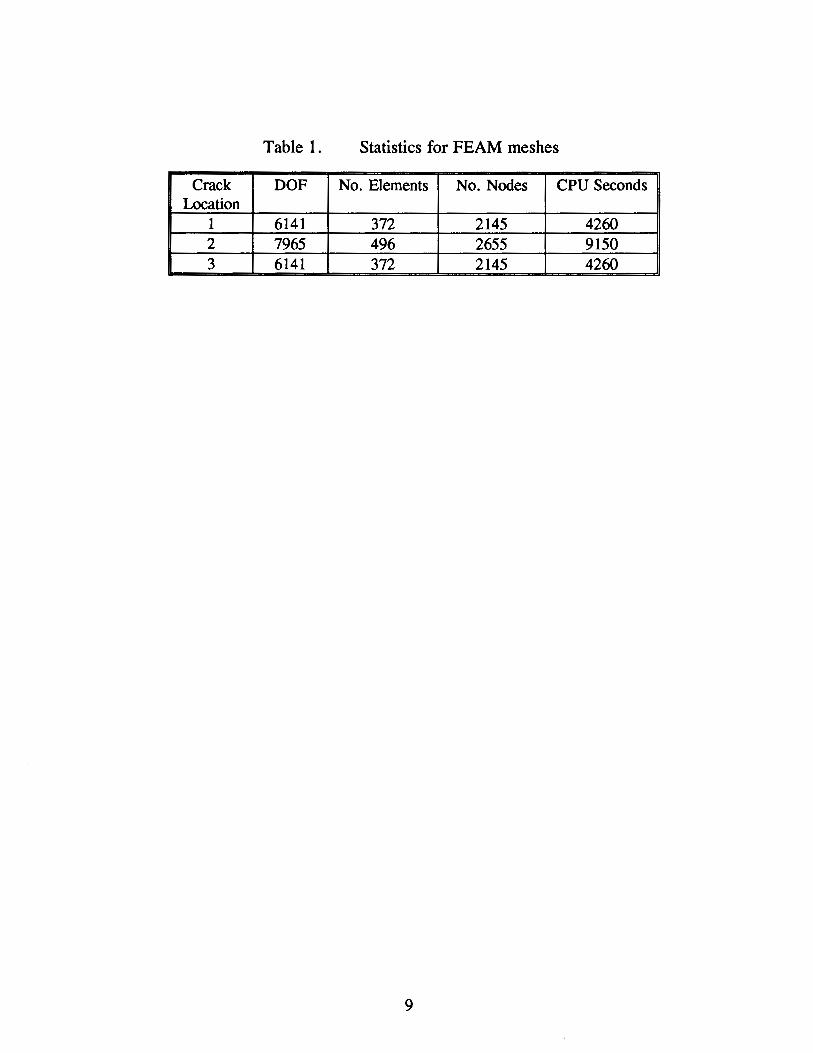
Table 1. Statistics for FEAM meshes
Crack DOF No. Elements No. Nodes CPU Seconds Location
1 6141 372 2145 4260 2 7965 496 2655 9150 3 6141 372 2145 4260
9
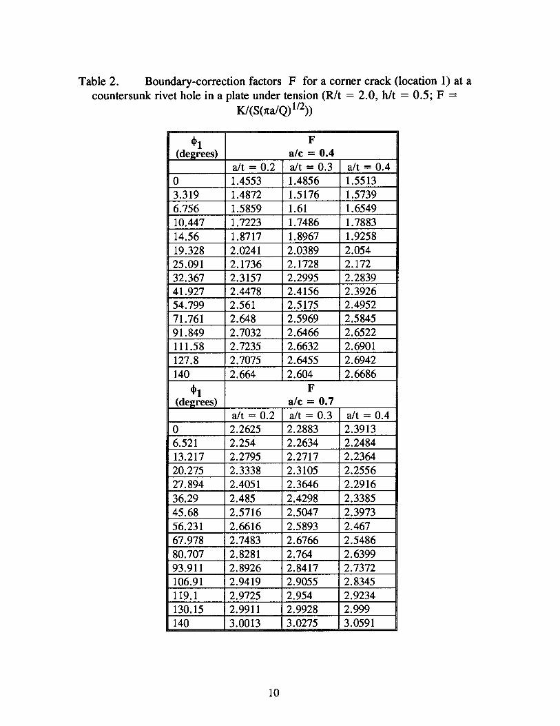
Table 2. Boundary-correction factors F for a corner crack (location 1) at a countersunk rivet hole in a plate under tension (R/t = 2.0, h/t = 0.5; F =
K/(S(7ta/Q) 112))
~1 F (de2rees) a/c = 0.4
aft= 0.2 aft= 0.3 aft = 0.4 0 1.4553 1.4856 1.5513 3.319 1.4872 1.5176 1.5739 6.756 1.5859 1.61 1.6549 10.447 1.7223 1.7486 1.7883 14.56 1.8717 1.8967 1.9258 19.328 2.0241 2.0389 2.054 25.091 2.1736 2.1728 2.172 32.367 2.3157 2.2995 2.2839 41.927 2.4478 2.4156 2.3926 54.799 2.561 2.5175 2.4952 71.761 2.648 2.5969 2.5845 91.849 2.7032 2.6466 2.6522 111.58 2.7235 2.6632 2.6901 127.8 2.7075 2.6455 2.6942 140 2.664 2.604 2.6686
~1 F (de2rees) a/c = 0.7
aft= 0.2 aft= 0.3 aft = 0.4 0 2.2625 2.2883 2.3913 6.521 2.254 2.2634 2.2484 13.217 2.2795 2.2717 2.2364 20.275 2.3338 2.3105 2.2556 27.894 2.4051 2.3646 2.2916 36.29 2.485 2.4298 2.3385 45.68 2.5716 2.5047 2.3973 56.231 2.6616 2.5893 2.467 67.978 2.7483 2.6766 2.5486 80.707 2.8281 2.764 2.6399 93.911 2.8926 2.8417 2.7372 106.91 2.9419 2.9055 2.8345 119.1 2.9725 2.954 2.9234 130.15 2.9911 2.9928 2.999 140 3.0013 3.0275 3.0591
10

Table 2. continued (R/t = 2.0, h/t = 0.5; F = K/(S(7ta/Q) 112))
cl>t F (degrees) a/c = 2.0
alt = 0.2 alt = 0.3 alt = 0.4 0 1.9677 2.0744 2.1281 21.66 1.9066 1.9834 2.018 39.558 1.8165 1.8649 1.8808 53.134 1.708 1.7351 1.7338 63.375 1.595 1.6054 1.5902 71.466 1.4758 1.4757 1.4519 78.236 1.3643 1.3572 1.3298 84.253 1.2833 1.2748 1.2477 89.926 1.2604 1.2536 1.2283 95.594 1.3093 1.3073 1.2877 101.6 1.4208 1.4295 1.4184 108.34 1.5659 1.5954 1.5966 116.39 1.7157 1.7788 1.8019 126.56 1.8929 2.0008 2.0558 140 2.258 2.4125 2.5052
11
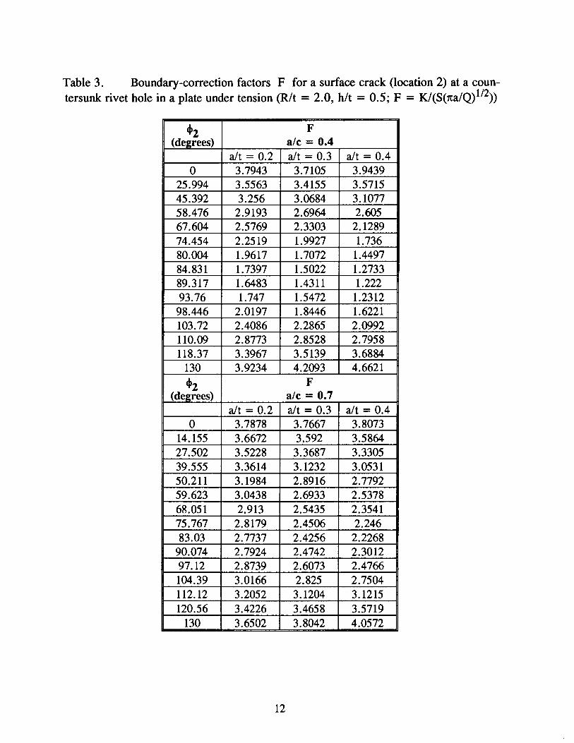
Table 3. Boundary-correction factors F for a surface crack (location 2) at a coun-tersunk rivet hole in a plate under tension (R/t = 2.0, h/t = 0.5; F = K/(S(7ta/Q) 112))
~2 F (degrees) a/c = 0.4
a/t = 0.2 a/t = 0.3 a/t = 0.4 0 3.7943 3.7105 3.9439
25.994 3.5563 3.4155 3.5715 45.392 3.256 3.0684 3.1077 58.476 2.9193 2.6964 2.605 67.604 2.5769 2.3303 2.1289 74.454 2.2519 1.9927 1.736 80.004 1.9617 1.7072 1.4497 84.831 1.7397 1.5022 1.2733 89.317 1.6483 1.4311 1.222 93.76 1.747 1.5472 1.2312
98.446 2.0197 1.8446 1.6221 103.72 2.4086 2.2865 2.0992 110.09 2.8773 2.8528 2.7958 118.37 3.3967 3.5139 3.6884
130 3.9234 4.2093 4.6621
~2 F (de2rees) a/c = 0.7
a/t = 0.2 a/t = 0.3 a/t = 0.4 0 3.7878 3.7667 3.8073
14.155 3.6672 3.592 3.5864 27.502 3.5228 3.3687 3.3305 39.555 3.3614 3.1232 3.0531 50.211 3.1984 2.8916 2.7792 59.623 3.0438 2.6933 2.5378 68.051 2.913 2.5435 2.3541 75.767 2.8179 2.4506 2.246 83.03 2.7737 2.4256 2.2268
90.074 2.7924 2.4742 2.3012 97.12 2.8739 2.6073 2.4766 104.39 3.0166 2.825 2.7504 112.12 3.2052 3.1204 3.1215 120.56 3.4226 3.4658 3.5719
130 3.6502 3.8042 4.0572
12

Table 3. continued (R/t = 2.0, h/t = 0.5; F = K/(S(1ta/Q) 112))
cl>z F (de2rees) a/c = 2.0
alt = 0.2 alt = 0.3 alt = 0.4 0 1.7661 1.7563 1.7846
4.047 1.7829 1.7688 1.7879 8.217 1.8501 1.8299 1.8375 12.643 1.9479 1.9222 1.9196 17.488 2.0624 2.032 2.0147 22.958 2.1801 2.148 2.1109 29.323 2.2931 2.2615 2.2038 36.943 2.3924 2.3638 2.2869 46.266 2.4734 2.4486 2.3572 57.747 2.5315 2.511 2.4123 71.575 2.5651 2.5484 2.4479 87.197 2.5773 2.5597 2.4652 103.13 2.5666 2.5484 2.463 117.7 2.5376 2.5185 2.4436 130 2.4933 2.4748 2.4123
13
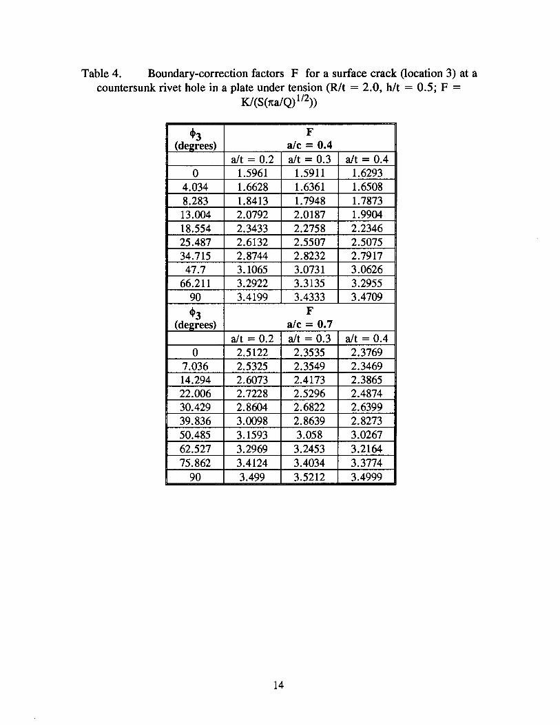
Table 4. Boundary-correction factors F for a surface crack (location 3) at a countersunk rivet hole in a plate under tension (R/t = 2.0, h/t = 0.5; F =
K/(S(7ta/Q) 112))
'3 F (degrees) a/c = 0.4
aft= 0.2 aft= 0.3 aft= 0.4 0 1.5961 1.5911 1.6293
4.034 1.6628 1.6361 1.6508 8.283 1.8413 1.7948 1.7873 13.004 2.0792 2.0187 1.9904 18.554 2.3433 2.2758 2.2346 25.487 2.6132 2.5507 2.5075 34.715 2.8744 2.8232 2.7917 47.7 3.1065 3.0731 3.0626
66.211 3.2922 3.3135 3.2955 90 3.4199 3.4333 3.4709
'3 F (de2rees) a/c = 0.7
aft= 0.2 aft= 0.3 aft = 0.4 0 2.5122 2.3535 2.3769
7.036 2.5325 2.3549 2.3469 14.294 2.6073 2.4173 2.3865 22.006 2.7228 2.5296 2.4874 30.429 2.8604 2.6822 2.6399 39.836 3.0098 2.8639 2.8273 50.485 3.1593 3.058 3.0267 62.527 3.2969 3.2453 3.2164 75.862 3.4124 3.4034 3.3774
90 3.499 3.5212 3.4999
14
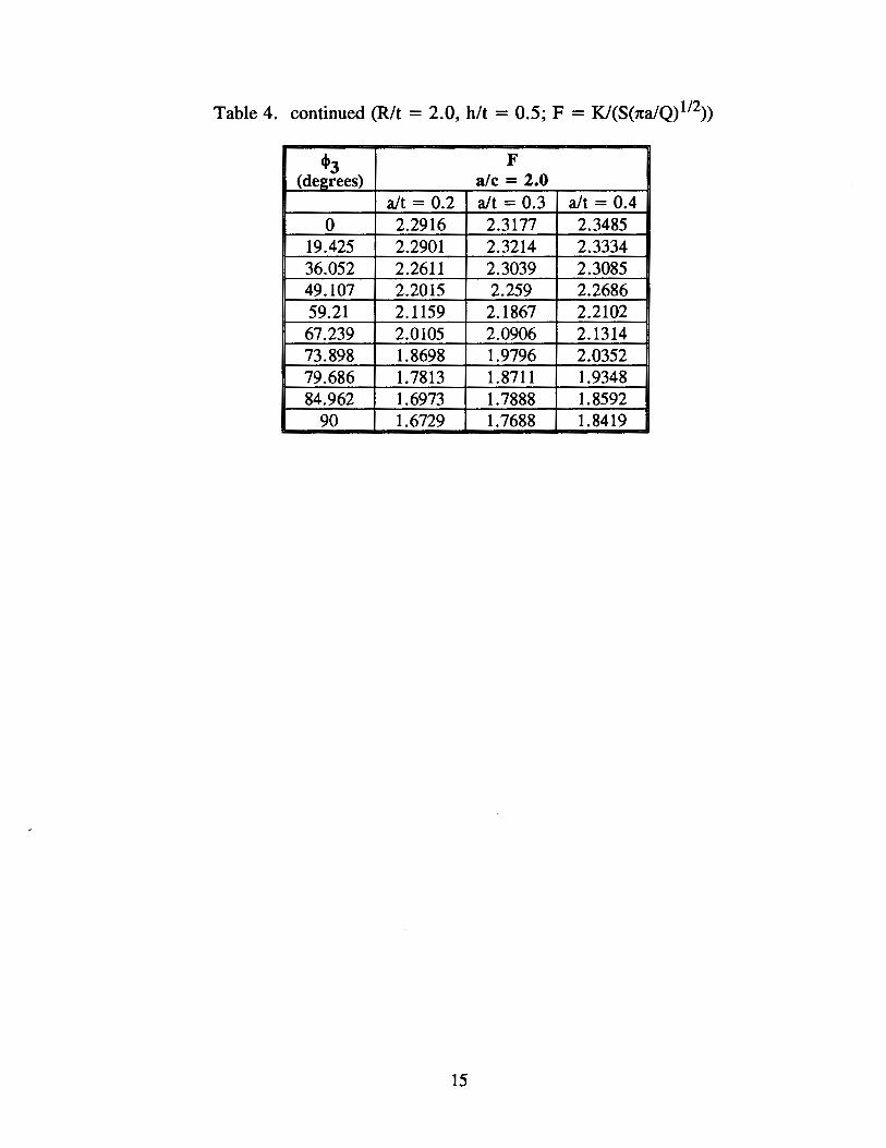
Table 4. continued (R/t = 2.0, h/t = 0.5; F = K/(S(7ta/Q) 112))
'3 F (degrees) a/c = 2.0
alt = 0.2 alt = 0.3 alt = 0.4 0 2.2916 2.3177 2.3485
19.425 2.2901 2.3214 2.3334 36.052 2.2611 2.3039 2.3085 49.107 2.2015 2.259 2.2686 59.21 2.1159 2.1867 2.2102 67.239 2.0105 2.0906 2.1314 73.898 1.8698 1.9796 2.0352 79.686 1.7813 1.8711 1.9348 84.962 1.6973 1.7888 1.8592
90 1.6729 1.7688 1.8419
15
---2W----+
2H R
HIW=2.0
S =Unit Pressure
WIR1 = 5.0
Figure 1. Specimen configuration and loading
16

t
Figure 2.
Figure 3.
Crack shapes and locations for countersunk hole; R/t = 2.0; h/t = 0.5; 8 = 50°; ale = 0.4, 0.7, and 2.0; aft = 0.2, 0.3 and 0.4
1 L---------~----------~--------~ 0 30 60 90
cp 3 (degrees)
Typical convergence study results, crack location 3, aft = 0.2 and ale = 0.4
17

Figure 4(a). Plan view of a typical finite-element mesh, 496 elements and 2655 nodes
Figure 4(b). Detailed view of finite-element mesh at crack location
18
3
a/t
0 0.2 0 0.3 ~ 0.4
a/c = 0.4
1 ~--~--~----~--~----~--~--~ 0 20 40 60 80 100 120 140
cp 1 (degrees)
Figure 5. Boundary correction factors F for crack location 1; ale = 0.4
4 a/t
0.2 0.3
3
F 2
a/c = 0.7
1 0 20 40 60 80 100 120 140
cp 1 (degrees)
Figure 6. Boundary correction factors F for crack location 1; ale = 0. 7
19

3
a/c = 2.0
1 ~--~--~----~--~--~----~--~ 0 w ~ ~ ~ 100 uo 1~
cp 1 (degrees)
Figure 7. Boundary correction factors F for crack location 1; ale = 2.0
5
4
F3
a/t ~ 0.4
/o 0.3
~00.2
1 ~--~----~--~----~--~----~--~ 0 20 40 60 80 100 120 140
cp 2 (degrees)
Figure 8. Boundary correction factors F for crack location 2; ale = 0.4
20

5 a/t
4
F 3
2 ~--~----~--~----~--~----~--~ 0 20 40 60 80 100 120 140
cp 2 (degrees)
Figure 9. Boundary correction factors F for crack location 2; ale = 0.7
3 a/t a/c = 2.0 0.2
-\0.3
F 0.4
2
1 ~--~--~----~--~----L---~--~ 0 20 40 60 80 100 120 140
cp 2 (degrees)
Figure 10. Boundary correction factors F for crack location 2; ale = 2.0
21