Dot Matrix Display using Micro controller 89c51
9
Microcontroller Based Dot Matrix Display Dot matrix display using microcontroller AT89C51 GHULAM MURTAZA ROLL NO. 9582 Bachelor of Engineering in Telecommunication Engineering National University of Modern Languages (NUML) H-9, Islamabad, Pakistan [email protected] Abstract— Now days microcontroller is used every where we can control different hardware with microcontroller in this project I used [1] microcontroller of ATMEL whose name is AT89C51 for display any text data it can either alphabets or number on Dot Matrix display. Output of microcontroller is not enough to drive the Dot Matrix display so that I use Transistors NEC 772 for rows drivers and ULN 2803 for column drivers. [2]Microcontroller just sends 7-bits data after specific time and sending data like burst on first column of display I use Serial In Parallel Out (SIPO) shift register SN74HC164N which is synchronized by microcontroller shifts data from first row to second then second to third and so on to the last fortieth column then jumps back to the first one. First I describe the functionality of all components then I pasted block diagram as well as circuit diagram in this report. You can found all information about this [4] project as after reading this report you will completely understood the function and purpose of this project. I. INTRODUCTION (AT89C51) The AT89C51 is a low-power, high-performance CMOS 8-bit microcomputer with 4K bytes of Flash programmable and erasable read only memory (PEROM). [3]The device is manufactured using ATMEL high-density nonvolatile memory technology and is compatible with the industry-standard MCS-51 instruction set and pin out. The on-chip Flash allows the program memory to be reprogrammed in-system or by a conventional nonvolatile memory programmer. By combining a versatile 8- bit CPU with Flash on a monolithic chip, the ATMEL AT89C51 is a powerful microcomputer which provides a highly- flexible and cost-effective solution to many embedded control applications. [5]There are 40 pins of microcontroller AT89C51, Each pin have it own function. Page No. 1 of 9
-
Upload
ghulammurtaza -
Category
Documents
-
view
2.805 -
download
6
Transcript of Dot Matrix Display using Micro controller 89c51
Microcontroller Based Dot Matrix DisplayDot matrix display using microcontroller AT89C51
GHULAM MURTAZAROLL NO. 9582
Bachelor of Engineering in Telecommunication EngineeringNational University of Modern Languages (NUML)
H-9, Islamabad, [email protected]
Abstract— Now days microcontroller is used every where we can control different hardware with microcontroller in this project I used [1] microcontroller of ATMEL whose name is AT89C51 for display any text data it can either alphabets or number on Dot Matrix display. Output of microcontroller is not enough to drive the Dot Matrix display so that I use Transistors NEC 772 for rows drivers and ULN 2803 for column drivers. [2]Microcontroller just sends 7-bits data after specific time and sending data like burst on first column of display I use Serial In Parallel Out (SIPO) shift register SN74HC164N which is synchronized by microcontroller shifts data from first row to second then second to third and so on to the last fortieth column then jumps back to the first one. First I describe the functionality of all components then I pasted block diagram as well as circuit diagram in this report. You can found all information about this [4] project as after reading this report you will completely understood the function and purpose of this project.
I. INTRODUCTION (AT89C51)
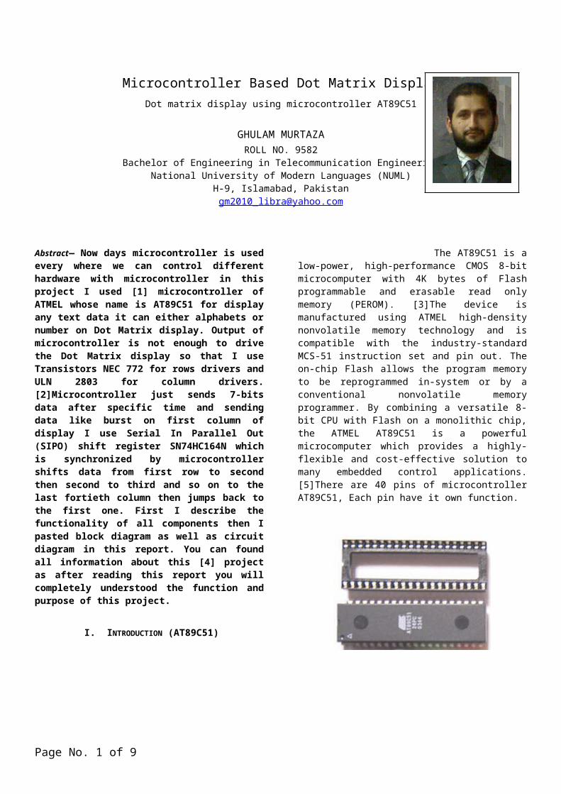
The AT89C51 is a low-power, high-performance CMOS 8-bit microcomputer with 4K bytes of Flash programmable and erasable read only memory (PEROM). [3]The device is manufactured using ATMEL high-density nonvolatile memory technology and is compatible with the industry-standard MCS-51 instruction set and pin out. The on-chip Flash allows the program memory to be reprogrammed in-system or by a conventional nonvolatile memory programmer. By combining a versatile 8-bit CPU with Flash on a monolithic chip, the ATMEL AT89C51 is a powerful microcomputer which provides a highly-flexible and cost-effective solution to many embedded control applications. [5]There are 40 pins of microcontroller AT89C51, Each pin have it own function.
Figure No. 1: Integrated circuit (AT89C51)
II. INTERNAL ARCHITECTURE OF AT89C51
[6]The internal architecture of AT89C51 consists of following parts:
It provides many functions (CPU, RAM, ROM, I/O, interrupt logic, timer, etc.) in a single package.
8-bit ALU, Accumulator and Registers; hence it is an 8-bit microcontroller.
8-bit data bus can access 8 bits of data in one operation.
16-bit address bus can access 216 memory locations, 64 KB (65536 locations) each of RAM and ROM.
On-chip RAM, 128 bytes (data memory). On-chip ROM 4 KB which is program memory. Four byte bi-directional input/output port. UART (serial port). Two 16-bit Counter/timers. Two-level interrupt priority.
Page No. 1 of 5
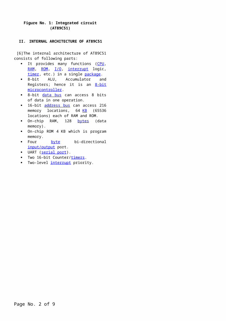
Figure No. 2: Microcontroller AT89C51 (Internal Architecture)
III. SPECIAL FUNCTION REGISTERS
Special Function Registers (SFRs) are given in the figure given below. Each of these registers as well as each bit they include, has its name, address in the scope of RAM and precisely defined purpose such as timer control, interrupt control, serial communication control etc. Even though there are 128 memory locations intended to be occupied by them, the basic core, shared by all types of AT89C51 microcontrollers, has only 21 such registers. Rest of locations is intentionally left unoccupied in order to enable the manufacturers to further develop microcontrollers keeping them compatible with the previous versions. It also enables programs written a long time ago for microcontrollers which are out of production now to be used today.
IV. DISPLAY OF PROJECT
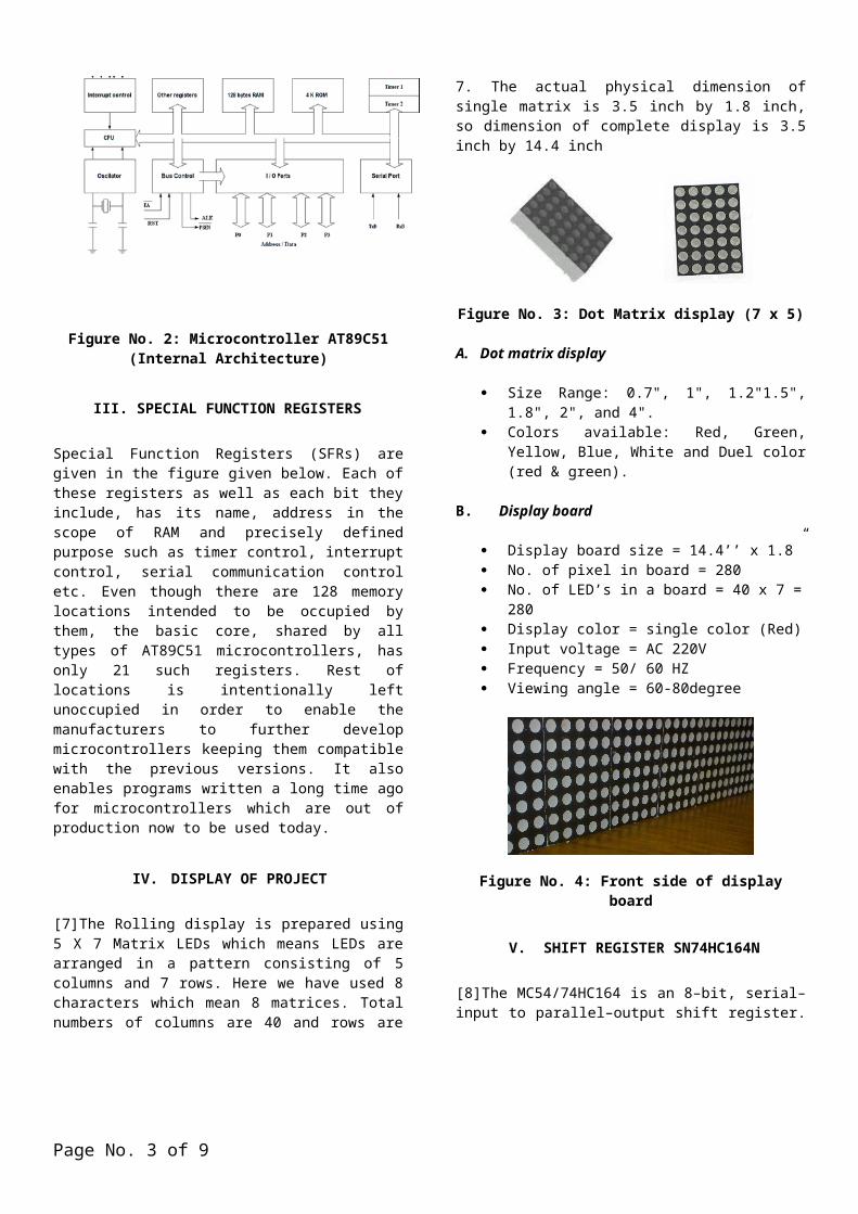
[7]The Rolling display is prepared using 5 X 7 Matrix LEDs which means LEDs are arranged in a pattern consisting of 5 columns and 7 rows. Here we have used 8 characters which mean 8 matrices. Total numbers of columns are 40 and rows are 7. The actual physical dimension of single matrix is 3.5 inch by 1.8 inch, so dimension of complete display is 3.5 inch by 14.4 inch
Figure No. 3: Dot Matrix display (7 x 5)
A. Dot matrix display
Size Range: 0.7", 1", 1.2"1.5", 1.8", 2", and 4". Colors available: Red, Green, Yellow, Blue, White
and Duel color (red & green).
B. Display board
Display board size = 14.4’’ x 1.8” No. of pixel in board = 280 No. of LED’s in a board = 40 x 7 = 280 Display color = single color (Red) Input voltage = AC 220V Frequency = 50/ 60 HZ Viewing angle = 60-80degree
Figure No. 4: Front side of display board
V. SHIFT REGISTER SN74HC164N
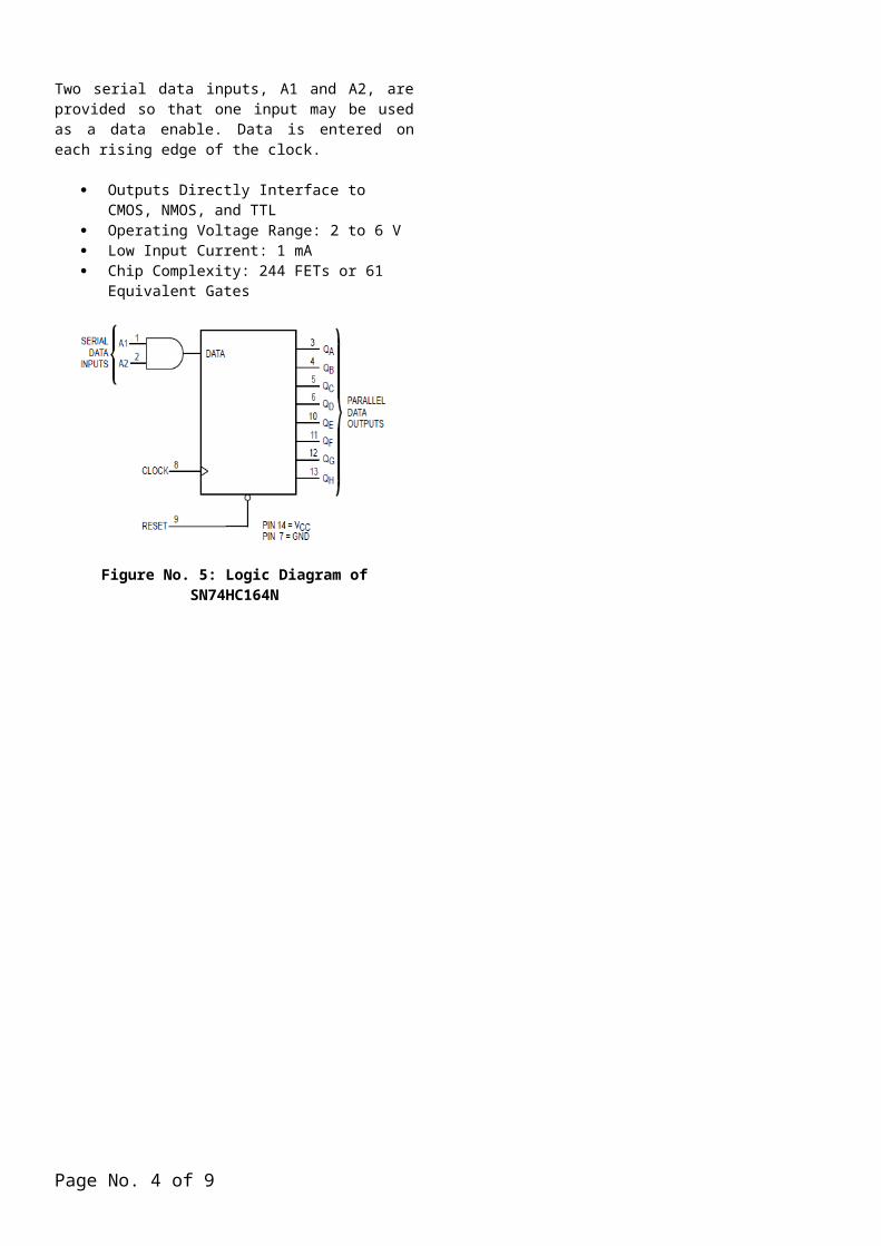
[8]The MC54/74HC164 is an 8–bit, serial–input to parallel–output shift register. Two serial data inputs, A1 and A2, are provided so that one input may be used as a data enable. Data is entered on each rising edge of the clock.
Outputs Directly Interface to CMOS, NMOS, and TTL
Operating Voltage Range: 2 to 6 V Low Input Current: 1 mA Chip Complexity: 244 FETs or 61 Equivalent
Gates
Figure No. 5: Logic Diagram of SN74HC164N
Page No. 2 of 5
VI. AMPLIFIER ULN2803
It has ground on pin number 9 and positive volts on pin number 10 remaining 8 are inputs and 8 outputs it just invert the input and amplifies the current of input to drive the outputs.
[9]It has just inverters and diodes inside it to invert the input. I use it at outputs of shift registers those have not an ability to drive the display board and I also want invert output so that this was the best choice to use in between shift register and display board.
Figure No. 6: Pin Configuration of ULN 2803
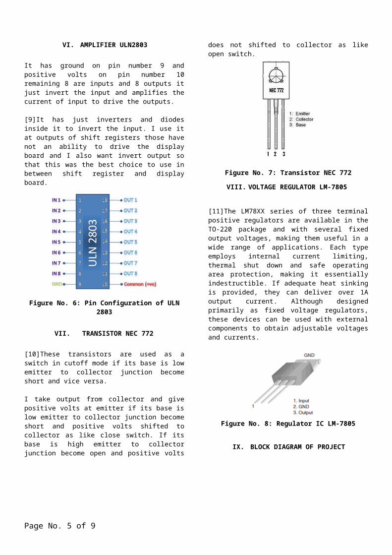
VII. TRANSISTOR NEC 772
[10]These transistors are used as a switch in cutoff mode if its base is low emitter to collector junction become short and vice versa.
I take output from collector and give positive volts at emitter if its base is low emitter to collector junction become short and positive volts shifted to collector as like close switch. If its base is high emitter to collector junction become open and positive volts does not shifted to collector as like open switch.
Figure No. 7: Transistor NEC 772
VIII. VOLTAGE REGULATOR LM-7805
[11]The LM78XX series of three terminal positive regulators are available in the TO-220 package and with several fixed output voltages, making them useful in a wide range of applications. Each type employs internal current limiting, thermal shut down and safe operating area protection, making it essentially indestructible. If adequate heat sinking is provided, they can deliver over 1A output current. Although designed primarily as fixed voltage regulators, these devices can be used with external components to obtain adjustable voltages and currents.
Figure No. 8: Regulator IC LM-7805
IX. BLOCK DIAGRAM OF PROJECT
[12]The Rolling display is prepared using 5 X 7 Matrix LED which means LED are arranged in a pattern consisting of 5 columns and 7 rows. Here we have used 8 characters which mean 8 matrices. Total numbers of columns are 40 and rows are 7. The actual physical dimension of single matrix is 3.5 inch by 1.8 inch, so dimension of complete display is 3.5 inch by 14.4 inch. Transistors NEC 772 for rows drivers and ULN 2803 for column drivers.
Figure No. 9: Block diagram
Page No. 3 of 5
X. WORKING
Microcontroller send 7-bit data using port 2 from pin 21 to 27, these bits are inverted and given to transistors 772 which again invert them also amplifies to drive rows of dot matrix display.
On the other hand when 7-bit data comes on first column of display it moved to next column then next data comes, rows and columns are synchronized with each other if they are not synchronized output is not correct and misplaced after some times and we see undefined output.
Serial-In Parallel-Out (SIPO) shift register is used to shift the data from column to column for which I used MC54/74HC164 which is an 8–bit, serial–input to parallel–output shift register. Next to this ULN 2803 is used which invert the output of shift register and amplifies to drive columns of display.
A. Control unit
This unit sifts data serial to parallel, select the matrices sequentially, control unit gets input from Microcontroller and then gives output to individual column of matrix. Only one column is selected at a time then shifted to the next one so as to display an output.
B. Control circuit diagram
Some other connections in diagram one is crystal oscillator across pin number 18 and 19 with 30pf capacitors shown in diagram. Reset pin 9 is active low because to set the controller if it is logic high microcontroller will reset. Pin number 31 is enable pin to enable the internal memory of microcontroller if it is low microcontroller take data from external memory but if it is active high then it takes data from internal memory.
Figure No. 11: Circuit Diagram
CONCLUSIONS
It is concluded that from this project I shall gain lot of knowledge about microcontroller and our mind will going to set for final project and we must gain knowledge about different components related to electronics were used in this project. I shall be very thanking full to our respected teacher who helped us in this project.
Page No. 4 of 5
REFERENCES
[1] Muhammad Ali Mazidi and Janice Gillispie Mazidi, The 8051 microcontroller and embedded systems.
[2] Myke Predko ,Michael Predko, Programming and customizing the 8051 microcontroller, ISBN 0-07-134192-7,
ISBN 0-07-134195-1.
[3] Kenneth J. Ayala , 3rd Edition, The 8051 microcontroller.
[4] Dogan Ibrahim , Microcontroller projects in C for the 8051, ISBN 0-7506-4640-3.
[5] Internal Architecture of Microcontroller, www.mikroe.com/en/books/8051book/ch2/images/01.gif.
[6] Pin configuration of microcontoller 89c51, http://www.datasheetdir.com/89C51+8051-Microcontrollers.
[7] Dot Matrix display, http://leddisplay.hisupplier.com/product-259086-5x7-led-dot-matrix-display.html.
[8] Serial In Parallel Out shift register, MC54/74HC164, http://www.seeedstudio.com/depot/74hc164-8bit-parallelout-
serial-shift-registers-p-169.html.
[9] ULN 2803, http://www.8051projects.net/forum-t9382-post.html.
[10] Transistor NEC 772, used as a switch in cutoff mode, http://upteks.en.alibaba.com/product/258113208-
209294587/PNP_Power_bipolar_Transistor_2SB772_TO_126_MP_5_.html.
[11] Voltage Regulator 7805, http://www.tipidpc.com/viewtopic.php?tid=147525.
[12] Block diagram, Rolling display using matrix LEDs, www.projectsof8051.com/projects/06-rolling-display.
Page No. 5 of 5