Dorothea Beam Engine House - · PDF filelapping equal sized steel plate, ... Dorothea beam...
27
l l l. L l Dorothea Beam Engine House Archaeological Recording Report No. 397 Prepared for Cyngor Gwynedd Council Ymddiriedolaeth Archaeolegol Gwynedd Archaeological Trust
Transcript of Dorothea Beam Engine House - · PDF filelapping equal sized steel plate, ... Dorothea beam...

l l l. L l
Dorothea Beam Engine House
Archaeological Recording
Report No. 397
Prepared for
Cyngor Gwynedd Council
Ymddiriedolaeth Archaeolegol Gwynedd Archaeological Trust

Dorothea Beam Engine House
Archaeological Recording
Project No. G 1633
Report No. 397
Prepared for
Cyngor Gwynedd Council
Text and Illustrations by Andrew Dutton
Ymddiriedolaeth Archaeolegol Gwynedd Archaeological Trust

I L
Archaeological Recording at Dorothea Beam Engine House
1. Introduction
The Oorothea Engine House sited in the Oorothea Slate Quarry at Nantlle, near Caernarfon, houses a Cornish Beam Engine that was used to pump out water from the adjoining quarry workings. The engine was built in 1904 and was used until the 1950s.
Plans for the restoration and repair of both engine and engine house have been prepared by the Welsh Mines Preservation Trust. The restoration scheme is divided into three stages, of which the removal of asbestos and recording of the beam engine comprise the first stage. The asbestos contamination was carried out by C&A Asbestos Removal Ltd and present and pending restoration work is undertaken by Oorothea Restorations Ltd (OR) . Gwynedd Archaeological Trust were contracted by OR Ltd to undertake the required archaeological recording within the present contract.
Archaeological recording at the Engine House complex was carried out at specific locations both during and on completion of decontamination work.
The Engine House is a Scheduled Ancient Monument (SAM No. C165) and all Works were carried out under Ancient Monument Consent to comply with the Ancient Monuments and Archaeological Areas Act (1979) .
2. Background
The Oorothea Beam Engine complex comprises the pump house and beam engine, the boiler house, boilers, fuel hopper, flue , chimneystack and windlass. The engine was designed by Nicholas Trestrail , last of the great Cornish pumping engineers, and built by Holman Bros. of Cambome, Cornwall in 1904. lt is housed within a custom built Engine House built of local slate but designed in Cornwall.
The Beam Engine was installed by 1906, its prime purpose to pump out the deep quarry workings, a task which previously, but increasingly less efficiently was undertaken by a series of waterwheels .
The Engine House structure remains in good sound condition and has been re-roofed in recent years.
The major components of the Engine itself are summarised below :
Beam: 34ft long, weighing some twenty-two and one half tons. The beam is apparently constructed of wrought iron, which is unusual. The massive beam is 6ft deep at the centre and some three feet at each end. The work rate was normally five strokes per minute (the maximum rate being nine per minute) . The inside stroke was 1Oft (at the piston), outside stroke 9ft (in the pumps), equivalent to one lift of the pumps at a depth of 460ft.
Cylinders: a single cylinder fourteen feet eight inches high, having a stroke of 10ft and a bore of 5ft 8in, operating at a boiler pressure of 38psi. No trouble of any serious kind was recorded throughout the working life of the installation, and the cylinder cover had not been lifted since it was first bolted in position .
Boilers : There are two boilers of Lancashire type, both the shells and the fittings, in all probability, supplied by Mather and Platt. The chimney is located at the end of a curving flue adjacent to the fuel hopper.
The engine is the only surviving example complete with boilers, headgear and winch . The latter is believed to have come from a ship and is almost entirely of non-ferrous metal.
L
In 1978 Dorothea Restorations Ltd recommended that items that might easily be removed from the site were taken into secure storage. As a result, the more vulnerable parts of the valve gear, controls etc were dismantled. Records were kept of the parts that were removed . At present these items reside at the Cadw depot on the Cibyn industrial estate, Caernarfon, an inventory made and their condition has been assessed by OR and GAT staff.
3. Archaeological Recording
Initial recording work was carried out following the removal of all accessible and loose asbestos that did not require any disassembling of the machinery.
Methodology
Photographic Record
A photographic survey was undertaken of the interior of the engine house prior to the start of any disassembling work using 35mm colour print film . The initial survey sought only to provide a record of the interior and the presence and location of items within the engine house to aid future management. Following the initial photographic survey, the engine house was cleaned of all loose asbestos so requiring the relocation or storage of particular items. Subsequently a more detailed photographic survey was undertaken to record the cylinders housing, which comprised wooden staves and steel panels enclosing the asbestos surrounding the cylinder body.
Additional photographs (colour print, colour slide and monochrome) were taken of the cylinder after it had been stripped to reveal the cast elements and all remaining asbestos removed from the main structure. The subsequent record reflects this and includes detail of the cockpit and crow beneath the middle (first) floor beam level.
The Drawn Record.
Detailed scale drawings were made of the cylinder casing prior to its removal and included individual, constructional as well as any decorative details at scales between 1:10 and 1: 50 as applicable. Elements of the middle floor (first floor ceiling) beams where also recorded.
The field drawings were subsequently transcribed digitally using Adobe Illustrator computer software and those drawings accompany this report.
Original drawings of the beam engine house are held at the Cornwall County Record Office. The archives have seven of Trestrail's original 1904 engine house drawings and photographic copies of these have been obtained. Although these have not been fully scrutin ised as yet nor any direct comparisons made in the field it is clear that they are not entirely commensurate with the existing monument. Nonetheless elements of these drawings have been used to put the present phase of recording into context where appropriate. Copies of the original drawings are appended to this report .
4. Synopsis
Two members of GAT staff undertook and completed the archaeological recording over a period of two days. In the first instance this was in the presence of OR staff who were in the process of dismantling the cylinder casing to facilitate the removal of asbestos encasing the casting. In the second instance recording took place after the removal of the cylinder casings on both the bottom (first) and middle (second) floors.
The lower floor casing (which is the main subject of this report) comprised three curving sections of lapping equal sized steel plate, with a shorter section of flat plate completing the circuit adjacent to the adjoining pipes to the rear of the cylinder. Attached around the periphery were five covers for the cylinder anchors in the floor. The main body of the cylinder was clad by vertically set wooden staves that interlocked by means of a steel tongue set into grooves running the length of the edge of the staves. These had been held in place by three metal bands that had encircled the cylinder but were now missing.

The staves had originally been varnished. The whole was bound together by a three-section iron collar that formed a junction between the staves and the lower steel panelling. Decoration on the panels and the anchor covers was still discernible and comprised of red and gold piping on a mid-green background.
A similar arrangement of decorated steel panels was apparent on the top section of the cylinder visible on the second (middle) floor.
Since the removal of the asbestos all the cylinder coverings have been left off and stored within the engine house.
A number of metal components and other items have been recovered from within the engine house during the clean up operation and these still require a provenance.
LIST OF APPENDICES :
1. Drawings
2. Selected Photographs
3. Photographic record
4. Trestrail's 1904 Archive plans

APPENDIX 1.
DRAWINGS
L
r- -
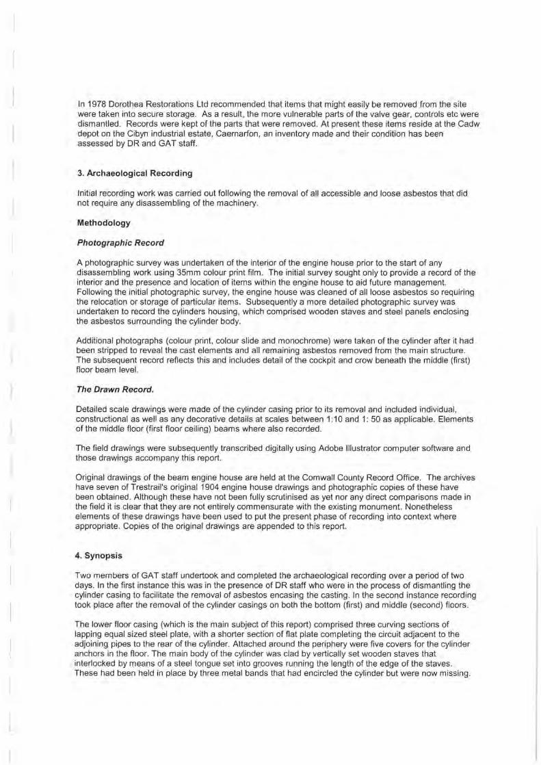
I ll us t ration o f a typica l Co rn is h P ump in g Eng i ne
extracted f ro m the Illu stra te d Cata logue o f the
Wi ll iams' Perran Found r y Co . 1870.
T he hi gh l ighted area a p proxima t es th e exten t of
the section of t he Do rothea cy l inde r reco rded in
lhe acco m panyi ng d rawings.
DOROTHEA BEAM ENGINE :SINGLE CYLINDER HOUSING
Title : DOROTHEA BEAM ENGINE : SINGLE CYLINDER HOUSING
Ymddiriedolaeth Archaeolegol Gwynedd I Client:
Gwynedd Archaeological Trust ft 01248 352535 Q 01248 370925 em;11l: gnt@~ll~n(!l>.r.o.uk
Craig Beuno : Ffordd y Garth : Bangor : LL57 2RT
Scale 1:20
0 100cm ·-- -
extended elevation showing principal components
Council
Scales:
1:40
27/10/00
LAD
Drawing number
C :\G1633_Dorothea _01 _A4.ai
1m
o I
1of2

500mm
door
door
r-------1 1 1 :.; -------:.!
: :_ ___________________________ ! : ~----------------- '--------·::::::::::::::::::' !
'
'
"~ I
' ~- - ----------- - - -~--:,~~~-'--·- --------------~ ·-------------------------- ---------------------------
' '
, ______ _
door
door
Title : DOROTHEA BEAM ENGINE : SINGLE CYLINDER HOUSING (showing arrangement of first floor supports)
Ymddiriedolaeth Archaeolegol Gwynedd Client: 11 Scales: 27/10/00
Gwynedd Archaeological Trust 1:40 LAD
'!!' 01248 352535 [;; 01248 370925 email: [email protected] - Drawing number
Cyngor Gwynedd Council C :\G 1633 _ Dorothea2 A4 .ai 2of2 Craig Beuno · Ffordd y Garth :Bangor : LL57 2RT -

Dorothea beam Engine House : Plan showing juxtaposition of First Floor (Cylinder level) , cockpit and crow. The structural detail is extracted from the original 1904 plans and incorporates elements of recent surveys carried out at specific locations.
entrance
---' ' \ ,. ... ~ \
-/ --...
/ '
\ I / D '} \ \ cylinder
1/ 1 /
I I I I I \ \2\~ !!) /~crow hole
\ 1
1,' (projected )
I -
' ' I
r--------------r-----+----~-----+--------------- ~ - -----
cock pit
t::::====::::::;-r·-- -- ----------------r.======-JL__~I
l D
Ymddiriedolaeth Archaeolegol Gwynedd
~OOd Areh~~lcgitaJI Tru~ '!! 01248 352535 1!!1 01248 370925 email: [email protected]. uk Shaft Craig Beuno · Ffordd y Garth · Bangor . LL57 2RT
Scales: 27/10/00
1:40 LAD
Drawing nu m ber 3 of 3 C :\G 1633 _ Dorothea - 03 _A4 .ai

I r
APPENDIX 2.
Selected Photographs

plate 1. The wrought iron beam.
r vie w from east
plate 2. The cylinder head, piston and linkage . Cylinder still enclosed. vie w from south east
plate 3. The cylinder head, piston , linkage and v alve chamber, cladding remo ved .
vie w from south east

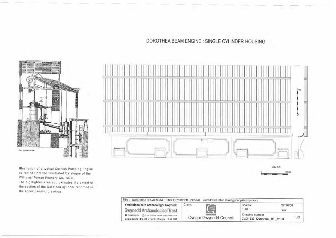
plate 4. The enclosed cylinder. Note location of missing bands . View from east.
plate 5. The cylinder revealed . Note trap to cock-pit at centre r ight. View from east.
l plate 6. The lower cylinder casing . Note decorative piping . View from west.

plate 1. The wrought iron beam. view from east
plate 2. The cylinder head, piston and linkage. Cylinder still enclosed. view from south east
plate 3. The cylinder head, piston, linkage and valve chamber, cladding removed . view from south east
plate 4. The enclosed cylinder. Note location of missing bands. View from east.
plate 5. The cylinder revealed. Note trap to cockpit at centre right. View from east.
plate 6. The lower cylinder casing. Note decorative piping. View from west.

r
plate 8. View into crow pit looking south .
plate 7. View into cockpit from trap , view north.
plate 9. Cock pit, view to trap and external door.

APPENDIX 3.
Photographic Record
L

Dorothea Beam Engine House : The Cylinder Refurbishment Film 01 colour print
Neg No. Description viewing position
01 first floor - cylinder view from EAST
02 first floor - cylinder and riser view from NW
03 first floor - cylinder at floor level view from NW
04 first floor - cyl inder& stairs view from SW
05 first floor - cylinder& stairs view from SW
06 first floor - cylinder and riser view from NW
07 first floor - rear of cylinder and riser view from NW
08 first floor - cylinder casing view from E
09 first floor - cylinder base view from SE
10 first floor - cylinder and riser view from NW
11 first floor - cylinder base, stairs and riser view from SW
12 first floor - cylinder, stairs and riser view from SW
13 first floor - rear of cylinder, riser & valve view from SE
14 first floor - cylinder & damaged casing view from SE
15 first floor - cylinder, damaged casing & 2nd floor joist view from SE
16 first floor - cylinder, riser and valve gear mount view from SE
17 first floor - cylinder, riser and valve gear mount view from W
18 first floor - cylinder, riser and valve gear mount & roof view from SW
19 first floor - rear of cylinder & riser view from S
20 first floor - riser and valve gear mount view from W
21 first floor - riser and valve gear mount view from SE
22 first floor- riser and valve gear mount view from SE
23 first floor - riser and valve gear mount and cylinder view from NW
24 first floor - riser and valve gear mount and cylinder view from NW
25 first floor - riser and valve gear mount view from NW
26 first floor - riser, and valve gear mount, cylinder & 2nd floor view from WNW
27 first floor - riser, and valve gear mount, cylinder & 2nd floor view from WNW
28 first floor - cylinder , riser & 2nd floor joist view from WNW
29 first floor - loose items & asb. bags view from W
30 first floor - stairway to 2nd floor view from NW
31 second floor - cylinder cover & 3rd floor stair view from NE
32 second floor cylinder cover piston view from SE
33 second floor - cylinder cover piston view from SE
34 second floor - cylinder cover piston & riser view from NW
35 second floor - cyl inder cover & valve housing view from W
36 second floor - cylinder cover & valve housing and stair view from NW
37 second floor- cylinder cover & valve housing and stair view from NE
l
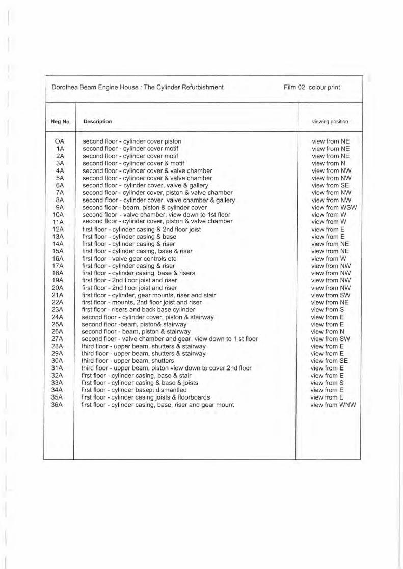
Dorothea Beam Engine House : The Cylinder Refurbishment Film 02 colour print
Neg No. Description viewing position
OA second floor - cylinder cover piston view from NE 1A second floor - cylinder cover motif view from NE 2A second floor - cylinder cover motif view from NE 3A second floor- cylinder cover & motif view from N 4A second floor - cylinder cover & valve chamber view from NW 5A second floor - cylinder cover & valve chamber view from NW 6A second floor - cyl inder cover, valve & gallery view from SE 7A second floor - cylinder cover, piston & valve chamber view from NW BA second floor - cylinder cover, valve chamber & gallery view from NW 9A second floor- beam, piston & cylinder cover view from WSW
10A second floor - valve chamber, view down to 1st floor view from W 11A second floor- cylinder cover, piston & valve chamber view from W 12A first floor - cylinder casing & 2nd floor joist view from E 13A first floor - cylinder casing & base view from E 14A first floor - cyl inder casing & riser view from NE 15A first floor- cylinder casing, base & riser view from NE 16A first floor- valve gear controls etc view from W 17A first floor- cyl inder casing & riser view from NW 18A first floor- cyl inder casing, base & risers view from NW 19A first floor - 2nd floor joist and riser view from NW 20A first floor - 2nd floor joist and riser view from NW 21A first floor - cyl inder, gear mounts, riser and stair view from SW 22A first floor - mounts, 2nd floor joist and riser view from NE 23A first floor - risers and back base cyl inder view from S 24A second floor- cylinder cover, piston & stairway view from E 25A second floor -beam, piston& stairway view from E 26A second floor- beam, piston & stairway view from N 27A second floor - valve chamber and gear, view down to 1 st floor view from SW 28A third floor - upper beam, shutters & stairway view from E 29A third floor- upper beam, shutters & stairway view from E 30A third floor- upper beam, shutters view from SE 31A third floor- upper beam, piston view down to cover 2nd floor view from E 32A first floor - cylinder casing , base & stair view from E 33A first floor - cylinder casing & base & joists view from S 34A first floor - cyl inder basept dismantled view from E 35A first floor - cylinder casing joists & floorboards view from E 36A first floor- cylinder casing , base, riser and gear mount view from WNW
l

Dorothea Beam Engine House : The Cylinder Refurbishment Film 03 colour print CD
Neg No. Description viewing position
1 lower floor - cock pit counterweight levers and pulleys view from N
2 lower floor - cock pit counterweight levers and pulleys view from N
6 lower floor - cock pit counterweight levers and pulleys view from N
7 lower floor- cock pit counterweight levers and pulleys view from N
8 lower floor - cock pit - ladder & ext.door view from S
9 lower floor - cock pit - ladder & ext.door view from S
10 lower floor - cock pit - ladder & detail of pulleys view from S
12 lower floor - cock pit - ladder & detail of pulleys view from S
13 lower floor - cock pit - south end detail of pulleys & weights. view from N
14 lower floor - cock pit detail & view down to crow view from E
15 crow pit detail view from cockpit access view from S
16 crow pit detail view from cockpit access view from S
17 lower floor - cock pit - general view from first floor access view from S
19 lower floor - cock pit - general view from first floor access view from S
21 first floor - exposed cylinder and cock pit trap view from E
22 first floor - exposed cylinder and cock pit trap view from E
23 first floor - exposed cylinder and riser view from SE
24 first floor- exposed cylinder and riser view from SE
25 first floor - exposed cylinder and riser view from SE
25 first floor - exposed cylinder and riser view from NE
27 second floor- exposed cylider, piston & valve chamber view from NE
28 second floor - exposed cylider, piston & valve chamber view from NE
29 second floor - exposed cylider, piston & valve chamber view from WSW
31 second floor- exposed cylider, piston & valve chamber view from WSW
32 second floor- exposed cylider, piston & valve chamber view from SE
33 second floor- exposed cylider, beam, piston & valve chamber view from SE
34 first floor - exposed cylinder and cock pit trap view from ENE

Dorothea Beam Engine House : The Cylinder Refurbishment Film 04 monochrome
Neg No. Description viewing position
1 lower floor - cock pit counterweight levers and pulleys view from N
2 lower floor - cock pit counterweight levers and pulleys view from N
6 lower floor - cock pit counterweight levers and pulleys view from N
7 lower floor - cock pit counterweight levers and pulleys view from N
8 lower floor - cock pit - ladder & ext.door view from S
9 lower floor - cock pit - ladder & ext.door view from S
10 lower floor - cock pit - ladder & detail of pulleys view from S
12 lower floor - cock pit - ladder & detail of pulleys view from S
13 lower floor- cock pit- south end detail of pulleys & weights. view from N
14 lower floor - cock pit detail & view down to crow view from E
15 crow pit detail view from cockpit access view from S
16 crow pit detail view from cockpit access view from S
17 lower floor - cock pit - general view from first floor access view from S
19 lower floor - cock pit - general view from first floor access view from S
21 first floor - exposed cylinder and cock pit trap view from E
22 first floor - exposed cylinder and cock pit trap view from E
23 first floor - exposed cylinder and riser view from SE
24 first floor - exposed cylinder and riser view from SE
25 first floor - exposed cylinder and riser view from SE
25 first floor - exposed cylinder and riser view from NE
27 second floor - exposed cylider, piston & valve chamber view from NE
28 second floor - exposed cylider, piston & valve chamber view from NE
29 second floor - exposed cylider, piston & valve chamber view from WSW
31 second floor - exposed cylider, piston & valve chamber view from WSW
32 second floor - exposed cylider, piston & valve chamber view from SE
33 second floor- exposed cylider, beam, piston & valve chamber view from SE
34 first floor - exposed cylinder and cock pit trap view from ENE

(
APPENDIX 4.
Nicholas Trestrail's 1904 Plans


r
r
f
l !, ; j I
I
I l I
!
l I
t -. ' I I
r

r
j ! ctift.--
.1 ,~ l) . I --1 'I : ~ ·~ 1

r
I
J I
(
-~ ·· ------~--------·,----r ~ ----~~-_,..Ill ............ _ ..,/ ~-·-r , . . ............. .......... ( •"' =r . lj- ·)' l e -,_-~ .I ' I' I' '·
I i \_ I '! ~ ( ' \ · I " I [ \
I . I • ' L- ~! t .
I l \
\ __ ,
I
~__j I ' I .
-~~- /"'-' ;. <!! .......... ~ . ) ~ ~ H-z ··- · o'/ . - ,
I i
~11/t>C..J-
~ I ... }.
-r-·-·-
\

___,. .
' ---~ 1- - - ------- - - -'---------·4-__ .. ---;;;;..z--.-.::::::r:--_ ____ ------,
,J i / ""-, ' / ~------ -~-------,-- ·- - -"--"----J
-~-
\
L· · .r.. · ·-CQ!iJ~--:_ C_L_::l? ~- . - ---
'--\ \
\ \
; J
J 1
-4 --- ~
I % ·
: /"" ! . .;. -;" / _;;
' -~ % - .. ;$ --
~- --f~

I I I I I I f
r
r
l l l l L L L L
L.
L