Donotusefornewdesigns! Type to be discontinued ......technical_datash… · Dimensions...
19
2003/10 – Subject to change – Products 2004/2005 1 / 1.3-1 Standard cylinders DNU/DNUL, ISO 6431 For new designs use standard cylinders DNC 1 / 1.2-24 Double-acting For contactless position sensing Comprehensive range of accessories ISO standard cylinders ISO 6431 1.3 Do not use for new designs! -U- Type to be discontinued
Transcript of Donotusefornewdesigns! Type to be discontinued ......technical_datash… · Dimensions...

2003/10 – Subject to change – Products 2004/2005 1 / 1.3-1
Standard cylinders DNU/DNUL, ISO 6431
For new designs use standard
cylinders DNC
� 1 / 1.2-24
�Double-acting
�For contactless position sensing
�Comprehensive range of
accessories
ISOstandardcylinders
ISO6431
1.3
Do not use for new designs!
-U- Type to be discontinued

Products 2004/2005 – Subject to change – 2003/101 / 1.3-2
Standard cylinders DNU/DNUL, ISO 6431Product range overview
Function Design Type Piston∅ Stroke Position sensing Cushioning
Adjustable
[mm] [mm] A PPV
Double- Basic version
acting DNU
Single-ended
piston rod
32, 40, 50, 63,
80, 100
25, 40, 50, 80,100, 125, 160,
200, 250, 300, 320, 400, 500
10 … 2,000
� �
DNU-…-S2
Through
piston rod
32, 40, 50, 63,
80, 100
– 10 … 2,000
� �
Non-rotating piston rod
DNUL 32 – 10 … 300
Single-ended 40 – 10 … 400� �
g
piston rod 50, 63 – 10 … 500� �
p
80, 100 – 10 … 600
ISOstandardcylinders
ISO6431
1.3
Do not use for new designs!
-U- Type to be discontinued

2003/10 – Subject to change – Products 2004/2005 1 / 1.3-3
Standard cylinders DNU/DNUL, ISO 6431Product range overview
Type Piston rod
Stainless steel
Heat resistant seal for temperatures
up to 150 °C
High corrosion protection � Page
S3 S6 S8
Basic version
DNU
Single-ended
piston rod
� � �
1 / 1.3-7
DNU-…-S2
Through
piston rod
– � –
1 / 1.3-7
Non-rotating piston rod
DNUL 1 / 1.3-7
Single-ended– � –
g
piston rod– � –
p
ISOstandardcylinders
ISO6431
1.3
Do not use for new designs!
-U- Type to be discontinued
Products 2004/2005 – Subject to change – 2003/101 / 1.3-4
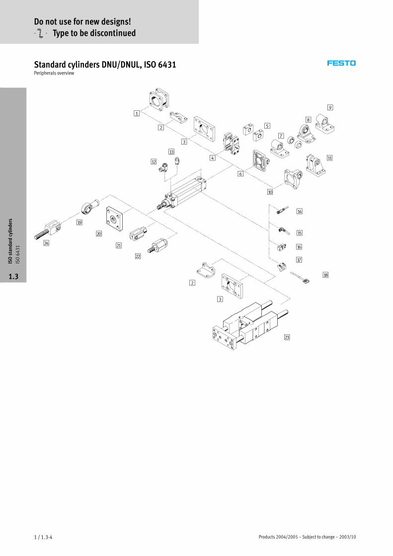
Standard cylinders DNU/DNUL, ISO 6431Peripherals overview
1
2
3
4
5
2
3
8
9
aB
aC
aI
bJ
aD
aE
aF
6
7
aG
bC
bD
bB
bA
aJ
aH
aA
ISOstandardcylinders
ISO6431
1.3
Do not use for new designs!
-U- Type to be discontinued

2003/10 – Subject to change – Products 2004/2005 1 / 1.3-5
Standard cylinders DNU/DNUL, ISO 6431Peripherals overview
Mounting attachments and accessories
Brief description � Page
1 Adapter kit
DPNN
For connecting two DNU cylinders with identical piston∅ to form a multi-position cylinder 1 / 1.3-13
2 Foot mounting
HN
For bearing and end caps 1 / 1.3-14
3 Flange mounting
FN
For bearing or end caps 1 / 1.3-14
4 Trunnion mounting kit
ZNU
For mounting anywhere along the cylinder profile barrel 1 / 1.3-15
5 Trunnion support
LNZ
– 1 / 1.3-15
6 Swivel flange
SN
For end caps 1 / 1.3-15
7 Clevis foot mounting
LN
– 1 / 1.3-17
8 Clevis foot mounting
LSN
With spherical bearing 1 / 1.3-17
9 Clevis foot mounting
LNG
– 1 / 1.3-17
aJ Swivel flange
SSN
With spherical bearing for clevis foot LBG 1 / 1.3-16
aA Clevis foot mounting
LBG
With non-rotating pivot pin 1 / 1.3-17
aB One-way flow control valve
GRLA
For speed regulation 1 / 1.3-17
aC Push-in fitting
QS
For connecting compressed air tubing with standard O.D. to CETOP RP 54 P Volume 3
aD Plug socket with cable, straight
SIM-M8
– 1 / 1.3-19
aE Plug socket with cable, angled
SIM-M8
– 1 / 1.3-19
aF Proximity sensors
SMEO-1/SMTO-1/SMPO-1
– 1 / 1.3-19
aG Sensor mounting kit
SMBU
For proximity sensor SMEO-1/SMTO-1 1 / 1.3-19
aH Sensor mounting kit
SMBS
For proximity sensor SMPO-1 1 / 1.3-19
aI Rod eye
SGS
With spherical bearing 1 / 1.3-18
bJ Coupling piece
KSG/KSZ
For compensating radial deviations 1 / 1.3-18
bA Rod clevis
SG
Permits a swivelling movement of the cylinder in one plane 1 / 1.3-18
bB Self-aligning rod coupler
FK
For compensating radial and angular deviations 1 / 1.3-18
bC Guided unit
FEN
To protect against torsion at high torque loads 1 / 1.3-18
bD Rod clevis
SGA
Suitable for spherical mounting of cylinders in conjunction with rod eye SGS 1 / 1.3-18
ISOstandardcylinders
ISO6431
1.3
Do not use for new designs!
-U- Type to be discontinued

Products 2004/2005 – Subject to change – 2003/101 / 1.3-6
Standard cylinders DNU/DNUL, ISO 6431Type code
DNU — 50 — 80 — PPV — A —
Type
Double-acting
DNU Standard cylinder
DNUL Standard cylinder, non-rotating
Piston∅ [mm]
Stroke [mm]
Cushioning
PPV Adjustable at both ends
Sensing
A Position sensing
Variants
S2 Through piston rod
S3 Stainless steel piston rod
S6 Heat resistant seal for temperatures up to
150 °C
S8 High corrosion protection
S26 Through piston rod with heat resistant seals
for temperatures up to 150 °C
ISOstandardcylinders
ISO6431
1.3
Do not use for new designs!
-U- Type to be discontinued

2003/10 – Subject to change – Products 2004/2005 1 / 1.3-7
Standard cylinders DNU/DNUL, ISO 6431Technical data
Function
-N- Diameter
32 … 125 mm
-T- Stroke length
2 … 2,000 mm
-W- www.festo.com/en/
Spare_parts_service
DIN
Variants
S2
S3
S6
S8
S26
DNGLDNU DNUL
General technical data
Piston∅ 32 40 50 63 80 100
Pneumatic connection G� G� G� G� G� G�
Piston rod thread M10x1.25 M12x1.25 M16x1.5 M16x1.5 M20x1.5 M20x1.5
Operating medium Filtered compressed air, lubricated or unlubricated
Design Pistong
Piston rod
Profile barrel
Cushioning Adjustable at both ends
Cushioning length [mm] 19 21 23 23 30 30
Position sensing Via proximity sensor
Type of mounting Via accessories
Mounting position Any
Operating and environmental conditions
Piston∅ 32 40 50 63 80 100
Operating pressure [bar] 12
Ambient temperature1) [°C] –20 … +80
1) Note operating range of proximity sensors
Forces [N]
Piston∅ 32 40 50 63 80 100
Theoretical force at 6 bar, 482 753 1,178 1,870 3,015 4,712,
advancing S2 393 586 924 1,601 2,615 4,221
Theoretical force at 6 bar, 415 633 990 1,682 2,720 4,418,
retracting S2 393 586 924 1,601 2,615 4,221
Technical data – Square piston rod
Piston∅ 32 40 50 63 80 100
Max. torque at the piston
rod1)[Nm] 0.8 1.1 1.5 1.5 3.0 3.0
1) The max. torque must also be observed when fitting mounting attachments to the piston rod.
ISOstandardcylinders
ISO6431
1.3
Do not use for new designs!
-U- Type to be discontinued

Products 2004/2005 – Subject to change – 2003/101 / 1.3-8
Standard cylinders DNU/DNUL, ISO 6431Technical data
Weights [g]
Piston∅ 32 40 50 63 80 100
Product weight at 0 mm stroke 483 727 1,146 1,674 2,662 3,864
Additional weight per 10 mm stroke 26 36 48 57 76 90
Materials
Sectional view
21
3
1
Standard cylinder
1 Bearing and end caps Aluminium
2 Cylinder barrel Anodised aluminium
3 Piston rod, tie rod High-alloy steel
– Seals Polyurethane
Max. permissible torque at the piston rod for DNUL Graphs� 1 / 1.3-9
Examples apply to piston∅ 32 mm
Example 1:
Stroke length =150 mm
Result: Permissible
Example 2:
Lateral force = 40 N
Result: Permissible
Example 3:
Stroke length =150 mm
Lever arm =100 mm
Lateral force = 9.5 N
Lever arm =84 mm
Stroke length =28 mm
Lever arm =20 mm Fq =
Max. Torque 800 Nmm
Leverarm 100 mmeve a 84 eve a 0
= 8 N
Result: Permissible
Fq 8 N < FQ max. 9.5 N
Fq
ISOstandardcylinders
ISO6431
1.3
Do not use for new designs!
-U- Type to be discontinued

2003/10 – Subject to change – Products 2004/2005 1 / 1.3-9
Standard cylinders DNU/DNUL, ISO 6431Technical data
Lateral force Fq as a function of the stroke length l and lever arm s
DNUL-32 DNUL-40
Max. torque = 800 Nmm
Max. stroke = 300 mm
Max. torque = 1,100 Nmm
Max. stroke = 400 mm
Fq[N]
s[mm]
l [mm] l [mm]
Fq[N]
s[mm]
DNUL-50/63 DNUL-80/100
Max. torque = 1,500 Nmm
Max. stroke = 500 mm
Max. torque = 3,000 Nmm
Max. stroke = 600 mm
Fq[N]
s[mm]
l [mm]
Fq[N]
s[mm]
l [mm]
ISOstandardcylinders
ISO6431
1.3
Do not use for new designs!
-U- Type to be discontinued

Products 2004/2005 – Subject to change – 2003/101 / 1.3-10
Standard cylinders DNU/DNUL, ISO 6431Technical data
Dimensions Download CAD data� www.festo.com/en/engineering
DNU/DNUL
DNUL
1 Socket head screw with female
thread for mounting
attachments
2 Regulating screw for adjustable
end-position cushioning
3 Mounting kit
SMBU-…-B for proximity sensor
4 Proximity sensor
SMEO-1/SMTO-1/SMPO-1
+ = plus stroke length
Variant S2/S26 – Through piston rod
+ = plus stroke length
++ = plus 2x stroke length
∅
[mm]
AM B
∅
f8
B1
f8
BG D4
∅
D5
∅
E EE J2 J3 J4 J5 J6
32 22 30 10 13 37 46 45 G� 7 – 25 43.7 37
40 24 35 12 13 46 56 54 G� 9 4.5 29 50.6 41
50 32 40 16 16 56 68 65 G� 11.5 5.5 33.5 59.1 45.5
63 32 42 16 19 70 84 80 G� 13 11.5 42 72.7 53
80 40 48 21 20 87 100 96 G� 17 16 49 84.1 60
100 40 52 21 20 107 132 126 G� 17.5 18 57.5 106.7 68.5
∅
[mm]
KK L1 L2 L7 MM
∅
f8
PL RT VA VD WH ZJ ZM �1
32 M10x1.25 16 94 9.5 12 9 M5 4 16 26 120 146 10
40 M12x1.25 20 105 6 16 12 M5 5.5 20 30 135 165 13
50 M16x1.5 25 106 4 20 12 M6 5 17 37 143 180 17
63 M16x1.5 28 115 – 20 14.5 M6 6 28 40 155 195 17
80 M20x1.5 34 124 – 25 14 M8 6 23 48 172 220 22
100 M20x1.5 40 134 – 25 16 M8 7 23 53 187 240 22
ISOstandardcylinders
ISO6431
1.3
Do not use for new designs!
-U- Type to be discontinued

2003/10 – Subject to change – Products 2004/2005 1 / 1.3-11
Standard cylinders DNU/DNUL, ISO 6431Technical data
Ordering data
Design Stroke
[mm]
Piston∅ 32 [mm]
Part No. Type1)Piston∅ 40 [mm]
Part No. Type1)Piston∅ 50 [mm]
Part No. Type1)
Basic version
25 14 121 DNU-32-25-PPV-A 14 132 DNU-40-25-PPV-A 14 143 DNU-50-25-PPV-A
40 14 122 DNU-32-40-PPV-A 14 133 DNU-40-40-PPV-A 14 144 DNU-50-40-PPV-A
50 14 123 DNU-32-50-PPV-A 14 134 DNU-40-50-PPV-A 14 145 DNU-50-50-PPV-A
80 14 124 DNU-32-80-PPV-A 14 135 DNU-40-80-PPV-A 14 146 DNU-50-80-PPV-A
100 14 125 DNU-32-100-PPV-A 14 136 DNU-40-100-PPV-A 14 147 DNU-50-100-PPV-A
125 14 126 DNU-32-125-PPV-A 14 137 DNU-40-125-PPV-A 14 148 DNU-50-125-PPV-A
160 14 127 DNU-32-160-PPV-A 14 138 DNU-40-160-PPV-A 14 149 DNU-50-160-PPV-A
200 14 128 DNU-32-200-PPV-A 14 139 DNU-40-200-PPV-A 14 150 DNU-50-200-PPV-A
250 14 129 DNU-32-250-PPV-A 14 140 DNU-40-250-PPV-A 14 151 DNU-50-250-PPV-A
300 14 130 DNU-32-300-PPV-A 14 141 DNU-40-300-PPV-A 14 152 DNU-50-300-PPV-A
320 34 704 DNU-32-320-PPV-A 34 705 DNU-40-320-PPV-A 34 706 DNU-50-320-PPV-A
400 32 473 DNU-32-400-PPV-A 32 475 DNU-40-400-PPV-A 32 477 DNU-50-400-PPV-A
500 32 474 DNU-32-500-PPV-A 32 476 DNU-40-500-PPV-A 32 478 DNU-50-500-PPV-A
Variable stroke 10 … 2,000 14 120 DNU-32-…-PPV-A 14 131 DNU-40-…-PPV-A 14 142 DNU-50-…-PPV-A
Variant S2 10 … 2,000 14 186 DNU-32-…-PPV-A-S2 14 187 DNU-40-…-PPV-A-S2 14 188 DNU-50-…-PPV-A-S2
Variant S3 10 … 2,000 158 844 DNU-32-…-PPV-A-S3 158 845 DNU-40-…-PPV-A-S3 158 846 DNU-50-…-PPV-A-S3
Variant S6 10 … 2,000 14 919 DNU-32-…-PPV-A-S6 14 920 DNU-40-…-PPV-A-S6 14 921 DNU-50-…-PPV-A-S6
Variant S8 10 … 2,000 158 850 DNU-32-…-PPV-A-S8 158 851 DNU-40-…-PPV-A-S8 158 852 DNU-50-…-PPV-A-S8
Variant S26 10 … 2,000 14 925 DNU-32-…-PPV-A-S26 14 926 DNU-40-…-PPV-A-S26 14 927 DNU-50-…-PPV-A-S26
With non-rotating piston rod
Variable stroke 10 … 300 15 602 DNUL-32-…-PPV-A – –
10 … 400 – 15 603 DNUL-40-…-PPV-A –
10 … 500 – – 15 604 DNUL-50-…-PPV-A
10 … 600 – – –
Variant S6 10 … 300 15 660 DNUL-32-…-PPV-A-S6 – –
10 … 400 – 15 661 DNUL-40-…-PPV-A-S6 –
10 … 500 – – 15 662 DNUL-50-…-PPV-A-S6
10 … 600 – – –
1) The scope of delivery includes a hex nut for the piston rod thread.
ISOstandardcylinders
ISO6431
1.3
Do not use for new designs!
-U- Type to be discontinued

Products 2004/2005 – Subject to change – 2003/101 / 1.3-12
Standard cylinders DNU/DNUL, ISO 6431Technical data
Ordering data
Design Stroke
[mm]
Piston∅ 63 [mm]
Part No. Type1)Piston∅ 80 [mm]
Part No. Type1)Piston∅ 100 [mm]
Part No. Type1)
Basic version
25 14 154 DNU-63-25-PPV-A 14 165 DNU-80-25-PPV-A 14 176 DNU-100-25-PPV-A
40 14 155 DNU-63-40-PPV-A 14 166 DNU-80-40-PPV-A 14 177 DNU-100-40-PPV-A
50 14 156 DNU-63-50-PPV-A 14 167 DNU-80-50-PPV-A 14 178 DNU-100-50-PPV-A
80 14 157 DNU-63-80-PPV-A 14 168 DNU-80-80-PPV-A 14 179 DNU-100-80-PPV-A
100 14 158 DNU-63-100-PPV-A 14 169 DNU-80-100-PPV-A 14 180 DNU-100-100-PPV-A
125 14 159 DNU-63-125-PPV-A 14 170 DNU-80-125-PPV-A 14 181 DNU-100-125-PPV-A
160 14 160 DNU-63-160-PPV-A 14 171 DNU-80-160-PPV-A 14 182 DNU-100-160-PPV-A
200 14 161 DNU-63-200-PPV-A 14 172 DNU-80-200-PPV-A 14 183 DNU-100-200-PPV-A
250 14 162 DNU-63-250-PPV-A 14 173 DNU-80-250-PPV-A 14 184 DNU-100-250-PPV-A
300 14 163 DNU-63-300-PPV-A 14 174 DNU-80-300-PPV-A 14 185 DNU-100-300-PPV-A
320 34 707 DNU-63-320-PPV-A 34 708 DNU-80-320-PPV-A 34 709 DNU-100-320-PPV-A
400 32 479 DNU-63-400-PPV-A 32 481 DNU-80-400-PPV-A 32 483 DNU-100-400-PPV-A
500 32 480 DNU-63-500-PPV-A 32 482 DNU-80-500-PPV-A 32 484 DNU-100-500-PPV-A
Variable stroke 10 … 2,000 14 153 DNU-63-…-PPV-A 14 164 DNU-80-…-PPV-A 14 175 DNU-100-…-PPV-A
Variant S2 10 … 2,000 14 189 DNU-63-…-PPV-A-S2 14 190 DNU-80-…-PPV-A-S2 14 191 DNU-100-…-PPV-A-S2
Variant S3 10 … 2,000 158 847 DNU-63-…-PPV-A-S3 158 848 DNU-80-…-PPV-A-S3 158 849 DNU-100-…-PPV-A-S3
Variant S6 10 … 2,000 14 922 DNU-63-…-PPV-A-S6 14 923 DNU-80-…-PPV-A-S6 14 924 DNU-100-…-PPV-A-S6
Variant S8 10 … 2,000 158 853 DNU-63-…-PPV-A-S8 158 854 DNU-80-…-PPV-A-S8 158 855 DNU-100-…-PPV-A-S8
Variant S26 10 … 2,000 14 928 DNU-63-…-PPV-A-S26 14 929 DNU-80-…-PPV-A-S26 14 930 DNU-100-…-PPV-A-S26
With non-rotating piston rod
Variable stroke 10 … 300 – – –
10 … 400 – – –
10 … 500 15 605 DNUL-63-…-PPV-A –
10 … 600 – 15 606 DNUL-80-…-PPV-A 15 607 DNUL-100-…-PPV-A
Variant S6 10 … 300 – – –
10 … 400 – – –
10 … 500 15 663 DNUL-63-…-PPV-A-S6 – –
10 … 600 – 15 664 DNUL-80-…-PPV-A-S6 15 665 DNUL-100-…-PPV-A-S6
1) The scope of delivery includes a hex nut for the piston rod thread.
ISOstandardcylinders
ISO6431
1.3
Do not use for new designs!
-U- Type to be discontinued

2003/10 – Subject to change – Products 2004/2005 1 / 1.3-13
Standard cylinders DNU/DNUL, ISO 6431Accessories
Adapter kit DPNN
Material:
Flange: Wrought aluminium alloy;
Threaded studs, hex nuts: Galvanised
steel
Free of copper and Teflon
+ = plus stroke length
Dimensions and ordering data
for∅ F1 ZJ Max. overall
stroke length
CRC1) Weight Part No. Type
[mm] [g]
-H- Note32 27 120 1,000 2 85 13 468 DPNN-32-H- Note40 27 135 1,000 2 115 13 469 DPNN-40
The maximum overall stroke length 50 32 143 1,000 2 210 13 470 DPNN-50may not be exceeded when 63 34 155 1,000 2 360 13 471 DPNN-63combining cylinders and the 80 42 172 1,000 2 620 13 472 DPNN-80adapter kit. 100 42 187 1,000 2 1,190 13 473 DPNN-100
1) Corrosion resistance class 2 according to Festo standard 940 070
Components requiring moderate corrosion resistance. Externally visible parts with primarily decorative surface requirements which are in direct contact with a
surrounding industrial atmosphere or media such as cooling or lubricating agents.
Connecting two cylinders with identical piston∅ as a 3 or 4-position cylinder
A 3 or 4-position cylinder consists of
two separate cylinders whose piston
rods advance in opposing directions.
This means that depending upon
actuation and stroke pattern, this type
of cylinder can assume up to four
positions. In each case the cylinder is
driven precisely against a stop. Note
that when one end of the piston rod is
fixed, the cylinder barrel executes the
movement. The cylinder must be con-
nected with flexible line connections.
To achieve 3 positions To achieve 4 positions
Two cylinders with identical stroke
length must be connected together.
Two cylinders with different stroke
lengths must be connected together.
ISOstandardcylinders
ISO6431
1.3
Do not use for new designs!
-U- Type to be discontinued

Products 2004/2005 – Subject to change – 2003/101 / 1.3-14
Standard cylinders DNU/DNUL, ISO 6431Accessories
Foot mounting HN
Material:
Galvanised steel
Free of copper and Teflon
+ = plus stroke length
Dimensions and ordering data
For∅ AB
∅
AH AO AT AU SA TR US XA CRC1) Weight Part No. Type
[mm] [g]
32 7 32 8 4 24 142 32 45 144 2 140 5 135 HN-32
40 9 36 10 5 28 161 36 54 163 2 220 5 136 HN-40
50 9 45 10 6 32 170 45 65 175 2 380 5 137 HN-50
63 9 50 15 6 35 185 50 80 190 2 580 5 138 HN-63
80 12 63 17 8 43 210 63 96 215 2 1,100 5 139 HN-80
100 14 71 14 8 43 220 75 126 230 2 1,480 5 140 HN-100
1) Corrosion resistance class 2 according to Festo standard 940 070
Components requiring moderate corrosion resistance. Externally visible parts with primarily decorative surface requirements which are in direct contact with a surrounding industrial atmosphere or media such as
cooling or lubricating agents.
Flange mounting FN
Material:
Galvanised steel
Free of copper and Teflon
+ = plus stroke length
Dimensions and ordering data
For∅ E FB
∅
MF R TF UF W ZF CRC1) Weight Part No. Type
[mm] [g]
32 45 7 10 32 64 77 16 130 2 80 5 141 FN-32
40 54 9 10 36 72 90 20 145 2 110 5 142 FN-40
50 65 9 12 45 90 110 25 155 2 190 5 143 FN-50
63 80 9 15 50 100 125 25 170 2 340 5 144 FN-63
80 96 12 18 63 126 154 30 190 2 520 5 145 FN-80
100 126 14 18 75 150 186 35 205 2 900 5 146 FN-100
1) Corrosion resistance class 2 according to Festo standard 940 070
Components requiring moderate corrosion resistance. Externally visible parts with primarily decorative surface requirements which are in direct contact with a surrounding industrial atmosphere or media such as
cooling or lubricating agents.
ISOstandardcylinders
ISO6431
1.3
Do not use for new designs!
-U- Type to be discontinued

2003/10 – Subject to change – Products 2004/2005 1 / 1.3-15
Standard cylinders DNU/DNUL, ISO 6431Accessories
Trunnion mounting kit ZNU
The mounting kit can be attached at
any position along the profile of the
cylinder barrel.
Material:
Galvanised steel
Free of copper and Teflon
+ = plus stroke length
Dimensions and ordering data
For∅ B1 C2 C3 TD
∅
TL TM UW CRC1) Weight Part No. Type
[mm] e9 [g]
32 30 65 80 12 12 50 65 2 300 14 210 ZNU-32
40 32 81 99 16 16 63 75 2 515 14 211 ZNU-40
50 34 93 111 16 16 75 86 2 710 14 212 ZNU-50
63 41 110 130 20 20 90 105 2 1,190 14 213 ZNU-63
80 44 130 150 20 20 110 120 2 1,590 14 214 ZNU-80
100 44 157 182 25 25 132 140 2 2,050 14 215 ZNU-100
1) Corrosion resistance class 2 according to Festo standard 940 070
Components requiring moderate corrosion resistance. Externally visible parts with primarily decorative surface requirements which are in direct contact with a surrounding industrial atmosphere or media such as
cooling or lubricating agents.
Trunnion support LNZ
Material:
Anodised aluminium
Dimensions and ordering data
For∅ CR
∅
DA
∅
FK
∅
FN HB
∅
KE NH TH UL CRC1) Weight Part No. Type
[mm] ±0.2 [g]
32 12 E10 11 12.5 ±0.1 25 6.6 6.8 15 36 50 2 90 6 184 LNZ-32
40/50 16 E10 15 18 ±0.1 36 9 9 18 36 55 2 150 6 185 LNZ-40/50
63/80 20 E10 18 20 ±0.1 40 11 11 20 42 65 2 215 6 186 LNZ-63/80
100 25 E10 20 25 ±0.1 50 14 13 25 50 75 2 380 6 187 LNZ-100/125
1) Corrosion resistance class 2 according to Festo standard 940 070
Components requiring moderate corrosion resistance. Externally visible parts with primarily decorative surface requirements which are in direct contact with a surrounding industrial atmosphere or media such as
cooling or lubricating agents.
ISOstandardcylinders
ISO6431
1.3
Do not use for new designs!
-U- Type to be discontinued

Products 2004/2005 – Subject to change – 2003/101 / 1.3-16
Standard cylinders DNU/DNUL, ISO 6431Accessories
Swivel flange SN
Material:
Die-cast aluminium
+ = plus stroke length
Dimensions and ordering data
For∅ CB CD FL L ML MR UB XC CRC1) Weight Part No. Type
[mm]
∅
[g]
32 26 10 22 14 54 10 45 142 2 110 5 153 SN-32
40 28 12 25 16 62 13 52 160 2 180 5 154 SN-40
50 32 12 27 16 70 16 60 170 2 260 5 155 SN-50
63 40 16 35 23 82 18 70 190 2 460 5 156 SN-63
80 50 16 38 24 102 18 90 210 2 700 5 157 SN-80
100 60 20 43 28 126 23 110 230 2 1,280 5 158 SN-100
1) Corrosion resistance class 2 according to Festo standard 940 070
Components requiring moderate corrosion resistance. Externally visible parts with primarily decorative surface requirements which are in direct contact with a surrounding industrial atmosphere or media such as
cooling or lubricating agents.
Swivel flange SSN
for clevis foot LBG,
with spherical bearing
+ = plus stroke length
Dimensions and ordering data
For∅ CN
∅
EP EX FL L MS XC CRC1) Weight Part No. Type
[mm] [g]
32 10 10.5 14 22 14 16 142 2 160 34 285 SSN-32
40 12 12 16 25 16 18 160 2 260 34 286 SSN-40
50 12 12 16 27 16 19 170 2 400 34 287 SSN-50
63 16 15 21 35 23 23 190 2 720 34 288 SSN-63
80 16 15 21 38 24 23 210 2 1,070 34 289 SSN-80
100 20 18 25 43 28 30 230 2 1,780 34 290 SSN-100
1) Corrosion resistance class 2 according to Festo standard 940 070
Components requiring moderate corrosion resistance. Externally visible parts with primarily decorative surface requirements which are in direct contact with a surrounding industrial atmosphere or media such as
cooling or lubricating agents.
ISOstandardcylinders
ISO6431
1.3
Do not use for new designs!
-U- Type to be discontinued

2003/10 – Subject to change – Products 2004/2005 1 / 1.3-17
Standard cylinders DNU/DNUL, ISO 6431Accessories
Ordering data – Mounting attachments Technical data� 1 / 10.1-2
Designation For∅ Part No. Type Designation For∅ Part No. Type
Clevis foot LN Clevis foot LNG
32 5 147 LN-32 32 33 890 LNG-32
40 5 148 LN-40 40 33 891 LNG-40
50 5 149 LN-50 50 33 892 LNG-50
63 5 150 LN-63 63 33 893 LNG-63
80 5 151 LN-80 80 33 894 LNG-80
100 5 152 LN-100 100 33 895 LNG-100
Clevis foot LSN Clevis foot LBG
32 5 561 LSN-32 32 31 761 LBG-32
40 5 562 LSN-40 40 31 762 LBG-40
50 5 563 LSN-50 50 31 763 LBG-50
63 5 564 LSN-63 63 31 764 LBG-63
80 5 565 LSN-80 80 31 765 LBG-80
100 5 566 LSN-100 100 31 766 LBG-100
Ordering data – One-way flow control valves Technical data� Volume 2
Connection Material Part No. Type
Thread for tubing OD
yp
G� 3 Metal design 193 142 GRLA-�-QS-3-D�
4
g
193 143 GRLA-�-QS-4-D
6 193 144 GRLA-�-QS-6-D
8 193 145 GRLA-�-QS-8-D
G� 6 193 146 GRLA-�-QS-6-D�
8 193 147 GRLA-�-QS-8-D
10 193 148 GRLA-�-QS-10-D
G� 6 193 149 GRLA-�-QS-6-D�
8 193 150 GRLA-�-QS-8-D
10 193 151 GRLA-�-QS-10-D
G� 12 193 152 GRLA-�-QS-12-D
ISOstandardcylinders
ISO6431
1.3
Core Range

Products 2004/2005 – Subject to change – 2003/101 / 1.3-18
Standard cylinders DNU/DNUL, ISO 6431Accessories
Ordering data – Piston rod attachments Technical data� 1 / 10.3-2
Designation For∅ Part No. Type Designation For∅ Part No. Type
Rod eye SGS Coupling piece KSG
32 9 261 SGS-M10x1,25 32 32 963 KSG-M10x1,25
40 9 262 SGS-M12x1,25 40 32 964 KSG-M12x1,25
50 9 263 SGS-M16x1,5 50 32 965 KSG-M16x1,5
63
9 ,
63
9 ,
80 9 264 SGS-M20x1,5 80 32 966 KSG-M20x1,5
100
9 ,
100
9 ,
Rod clevis SGA Coupling piece KSZ
32 32 954 SGA-M10x1,25 32 36 125 KSZ-M10x1,25
40 10 767 SGA-M12x1,25 40 36 126 KSZ-M12x1,25
50 10 768 SGA-M16x1,5 50 36 127 KSZ-M16x1,25
63
,
63
,
80 10 769 SGA-M20x1,5 80 36 128 KSZ-M20x1,25
100
9 ,
100
,
Rod clevis SG Self-aligning rod coupler FK
32 6 144 SG-M10x1,25 32 6 140 FK-M10x1,25
40 6 145 SG-M12x1,25 40 6 141 FK-M12x1,25
50 6 146 SG-M16x1,5 50 6 142 FK-M16x1,5
63
,
63
,
80 6 147 SG-M20x1,5 80 6 143 FK-M20x1,5
100
,
100
,
Ordering data – Guide units Technical data� 1 / 10.4-2
For∅ Stroke With recirculating ball bearing guide With sliding bearing guide
[mm] [mm] Part No. Type Part No. Type
32 10 … 500 33 484 FEN-32-…-KF -U- 19 171 FEN-32-… -U-
40
5
33 485 FEN-40-…-KF -U- 19 172 FEN-40-… -U-
50 33 486 FEN-50-…-KF -U- 19 173 FEN-50-… -U-
63 33 487 FEN-63-…-KF -U- 19 174 FEN-63-… -U-
80 33 488 FEN-80-…-KF -U- 19 175 FEN-80-… -U-
100 33 489 FEN-100-…-KF -U- 19 176 FEN-100-… -U-
ISOstandardcylinders
ISO6431
1.3
Core Range
Do not use for new designs!
-U- Type to be discontinued FEN-32 … 100

2003/10 – Subject to change – Products 2004/2005 1 / 1.3-19
Standard cylinders DNU/DNUL, ISO 6431Accessories
Ordering data – Rectangular proximity sensor, magneto-resistive Technical data� 1 / 10.2-73
Mounting Switch Electrical connection Cable length Part No. Typeg
output Cables M8 plug [m]
yp
NO contact
Via accessories PNP 3-wire – 2.5 151 683 SMTO-1-PS-K-LED-24-C
– 3-pin – 151 685 SMTO-1-PS-S-LED-24-C
NPN 3-wire – 2.5 151 684 SMTO-1-NS-K-LED-24-C
– 3-pin – 151 686 SMTO-1-NS-S-LED-24-C
Ordering data – Rectangular proximity sensor, magnetic reed Technical data� 1 / 10.2-73
Mounting Electrical connection Cable length Part No. Typeg
Cables M8 plug [m]
yp
NO contact
Via accessories 3-wire – 2.5 30 459 SMEO-1-LED-24-B
3-wire – 5.0 151 672 SMEO-1-LED-24-K5-B
– 3-pin – 150 848 SMEO-1-S-LED-24-B
Ordering data – Mounting kit for proximity sensor SMEO/SMTO-1 Technical data� 1 / 10.2-88
For∅ Mounting Part No. Type
32 … 50 mm On the cylinder profile barrel 36 173 SMBU-1-B
63 … 100 mm 36 174 SMBU-2-B
Ordering data – Rectangular proximity sensor, pneumatic Technical data� 1 / 10.2-73
Mounting Pneumatic connection Part No. Type
3/2-way valve, normally closed
Via accessories Barbed fitting for tubing ID of 3 mm 31 008 SMPO-1-H-B
Ordering data – Mounting kit for proximity sensor SMPO-1 Technical data� 1 / 10.2-88
For∅ Mounting Part No. Type
32 mm Directly on the cylinder profile barrel 150 216 SMBU-1-H-32
63 … 100 mm 36 174 SMBU-2-B
32 … 100 mm On the cylinder profile barrel via clamping strap 151 226 SMBS-2
Ordering data – Plug sockets Technical data� 1 / 10.2-108
Mounting Switch output Connection Cable length Part No. Typeg
PNP NPN [m]
yp
Straight socket
M8 union nut� �
3-pin 2.5 159 420 SIM-M8-3GD-2,5-PU� �
3 p
5 159 421 SIM-M8-3GD-5-PU
Angled plug socket
M8 union nut� �
3-pin 2.5 159 422 SIM-M8-3WD-2,5-PU� �
3 p
5 159 423 SIM-M8-3WD-5-PU
ISOstandardcylinders
ISO6431
1.3
Core Range