Données techniques Technical data - Clufix · Ø T 2 2.5 3 3.5 4568 Ep min ≥ 1 mm Ep min ...
4
2009.A 2009.A 323 Ces valeurs sont indicatives car elles dépendent de la nuance de la matière support. Pour des applications nécessitant une pose au delà des valeurs préconisées ci-dessus, LA CLUSIENNE-CLUFIX propose des produits sur mesure. Because the values depend on the grade of the workpiece material, they are given as guidelines only. For applications requiring installation beyond the values recommended above, LA CLUSIENNE-CLUFIX offers custom-made products. Préconisation sur la localisation des trous Recommendation on the location of holes Afin de garantir un sertissage optimal et pour éviter toute déformation de la tôle néfaste à la tenue de STUDFIX ™ , il est préconisé de respecter les distances (tableaux ci- dessous) entre : - les axes de deux trous poinçonnée (Dt) ; - le bord de tôle et l’axe du poinçonnage (Db) ; - l’axe du poinçonnage et le début du rayon de pliage (Dp). In order to guarantee optimal crimping, and to avoid any deformation of the sheet liable to adversely affect the STUDFIX ™ bond, compliance is recommended with the distances (shown in the table below) between: - two punched holes (Dt) - the edge of the sheet and the punching axis (Db) - the punching axis and the start of the bend radius (Dp) Ø M M 2 M 2.5 M 3 M 3.5 M 4 M 5 M 6 M 8 Type F Type T Ø T 2 2.5 3 3.5 4 5 6 8 Ep min ≥ 1 mm Ep min ≥ 0.5 mm Dt 7.2 7.9 8.1 9.6 10.9 12.3 14.2 17.6 Db 5.2 5.4 5.6 6.4 6.9 7.3 8.2 9.6 Dp (ep ≤ 3 mm) 3.5 3.5 3.5 4.1 4.75 5.25 5.75 7 Dp (3 < ep < 6 mm) - - - - 6.5 7 7.5 8.7 Type F ou T F or T type Ø M M 4 M 5 M 6 M 8 M10 Type H Type L Ø T 4 5 6 8 10 Ep min ≥ 1.2 mm Ep min ≥ 1 mm Dt 13.5 15.7 17.5 20.7 23.7 Db 9.5 10.7 11.5 12.7 13.7 Dp (ep ≤ 3 mm) 4.75 5.25 5.75 7 8.25 Dp (3 < ep < 6 mm) 6.5 7 7.5 8.7 10 Type H ou L H or L type Ø M M 2 M 2.5 M 3 M 3.5 M 4 M 5 Type R Ø T 2 2.5 3 3.5 4 5 Ep min ≥ 1 mm Dt 4.6 5.3 6.3 7.3 8.2 10.6 Db 2 2.8 3.3 3.8 4.2 5.6 Dp (ep ≤ 3 mm) 3.5 3.5 3.5 4.1 4.75 5.25 Dp (3 < ep < 6 mm) - - - - 6.5 7 Type R R type Données techniques Technical data 322 Préparation de la pièce à assembler Preparation of the workpiece to be assembled Diamètre de trou Ø T2 selon type de tête Ø T2 hole diameter according to head type Ø M M 2 M 2.5 M 3 M 3.5 M 4 M 5 M 6 M 8 M10 Ø T2 type F, T, I min 2.1 2.6 3.1 3.6 4.1 5.1 6.1 8.1 10.1 max 2.7 3.3 3.8 4.4 5.0 5.8 7.1 8.8 11.0 Ø T2 type R min 2.1 2.6 3.1 3.6 4.1 5.1 - - - max 2.4 2.8 3.3 3.9 4.3 5.5 - - - Ø T2 type H, L min - - - - 4.1 5.1 6.1 8.1 10.1 max - - - - 5.3 6.4 7.7 10.3 12.9 Ø T2 Ces quatre processus peuvent être utilisés pour la réalisation du trou recevant STUDFIX ™ . Toutefois, la qualité de préparation est prépondérante pour garantir un sertissage optimal et donc une tenue mécanique élevée. Il est donc par exemple conseillé d’utiliser un poinçon correctement affûté pour limiter l’écrouissage du trou et minorer la zone d’arrachement. These four processes can be used to create the hole destined to receive the STUDFIX ™ . Quality of preparation is, however, of overriding importance in guaranteeing optimal crimping which will result in high mechanical resistance. Use of a precision-sharpened punch is, for example, recommended - in order to limit strain-hardening of the hole and minimize the rupture zone. - Poinçonnage - Perçage au foret - Découpe laser - Découpe jet d'eau Punching Drilling Laser cutting Water jet cutting Processus de réalisation Preparation Process Poinçon Punch Zone écrouie Zone de découpe Zone d’arrachement Strain-hardened zone Cutting zone Rupture zone Pour effectuer la pose des goujons type I à tête invisible, il est nécessaire de réaliser un lamage en respectant les caractéristiques de diamètre (haut de page) et de profondeur P indiqués dans les fiches produits. Selon la hauteur du pilote (court ou long) l'épaisseur mini du support est de 1.5 mm ou 2.5 mm. To mount I type concealed head studs, it is necessary to carry out spot facing, in compliance with the characteristics for dia- meter (see top of page) and depth (‘P’: see data sheets). The minimum thickness of the metal sheet is 1.5 mm or 2.5 mm, depending on the height of the shank (short or long). Préparation du support selon goujon Workpiece preparation according to stud unité : mm (tolérances disponibles dans les fiches produits) dimensions: mm (tolerance provided in the data sheets) 2.5 M 2.5 4.35 3.5 M 3.5 7.35 Diamètre de trou Hole diameter Type F, R, T, H, ou L : F, R, T, H or L type: Type I : I type: 2.0 M 2 4.35 Ø 2 3.0 M 3 4.35 3.5 Ø 3 4.0 M 4 7.35 4.5 Ø 4 5.0 M 5 7.9 5.5 Ø 5 6.0 M 6 6.5 Ø 6 8.0 M 8 10.0 M 10 Type P : P type:
-
Upload
trinhduong -
Category
Documents
-
view
214 -
download
0
Transcript of Données techniques Technical data - Clufix · Ø T 2 2.5 3 3.5 4568 Ep min ≥ 1 mm Ep min ...

2009.A 2009.A
323
Ces valeurs sont indicatives car elles dépendent de la nuance de lamatière support. Pour des applications nécessitant une pose au delà des valeurs préconisées ci-dessus, LA CLUSIENNE-CLUFIX propose desproduits sur mesure.
Because the values depend on the grade of the workpiece material, they are given as guidelines only. For applications requiring installation beyond the values recommended above, LA CLUSIENNE-CLUFIX offers custom-madeproducts.
Préconisation sur la localisation des trous Recommendation on the location of holes
Afi n de garantir un sertissage optimal et pour éviter toute déformation de la tôle néfaste à la tenue de STUDFIX™, il est préconiséde respecter les distances (tableaux ci-dessous) entre :
- les axes de deux trous poinçonnée (Dt) ;- le bord de tôle et l’axe du poinçonnage
(Db) ;- l’axe du poinçonnage et le début du
rayon de pliage (Dp).
In order to guarantee optimal crimping, and to avoid any deformation of the sheet liable to adversely affect the STUDFIX™ bond,compliance is recommended with thedistances (shown in the table below) between:
- two punched holes (Dt)- the edge of the sheet and the punching
axis (Db)- the punching axis and the start of the
bend radius (Dp)
Ø M M 2 M 2.5 M 3 M 3.5 M 4 M 5 M 6 M 8 Type F Type TØ T 2 2.5 3 3.5 4 5 6 8
Ep min ≥ 1 mm Ep min ≥ 0.5 mm
Dt 7.2 7.9 8.1 9.6 10.9 12.3 14.2 17.6
Db 5.2 5.4 5.6 6.4 6.9 7.3 8.2 9.6
Dp (ep ≤ 3 mm) 3.5 3.5 3.5 4.1 4.75 5.25 5.75 7
Dp (3 < ep < 6 mm) - - - - 6.5 7 7.5 8.7
Type F ou T F or T type
Ø M M 4 M 5 M 6 M 8 M10 Type H Type LØ T 4 5 6 8 10
Ep min ≥ 1.2 mm Ep min ≥ 1 mm
Dt 13.5 15.7 17.5 20.7 23.7
Db 9.5 10.7 11.5 12.7 13.7
Dp (ep ≤ 3 mm) 4.75 5.25 5.75 7 8.25
Dp (3 < ep < 6 mm) 6.5 7 7.5 8.7 10
Type H ou L H or L type
Ø M M 2 M 2.5 M 3 M 3.5 M 4 M 5 Type RØ T 2 2.5 3 3.5 4 5
Ep min ≥ 1 mm
Dt 4.6 5.3 6.3 7.3 8.2 10.6
Db 2 2.8 3.3 3.8 4.2 5.6
Dp (ep ≤ 3 mm) 3.5 3.5 3.5 4.1 4.75 5.25
Dp (3 < ep < 6 mm) - - - - 6.5 7
Type R R type
Données techniquesTechnical data
322
Préparation de la pièce à assembler Preparation of the workpiece to be assembledDiamètre de trou Ø T2 selon type de tête Ø T2 hole diameter according to head type
Ø M M 2 M 2.5 M 3 M 3.5 M 4 M 5 M 6 M 8 M10
Ø T2 type F, T, Imin 2.1 2.6 3.1 3.6 4.1 5.1 6.1 8.1 10.1
max 2.7 3.3 3.8 4.4 5.0 5.8 7.1 8.8 11.0
Ø T2 type Rmin 2.1 2.6 3.1 3.6 4.1 5.1 - - -
max 2.4 2.8 3.3 3.9 4.3 5.5 - - -
Ø T2 type H, Lmin - - - - 4.1 5.1 6.1 8.1 10.1
max - - - - 5.3 6.4 7.7 10.3 12.9
Ø T2
Ces quatre processus peuvent être utilisés pour la réalisation du trourecevant STUDFIX™. Toutefois, la qualité de préparation estprépondérante pour garantir un sertissage optimal et donc une tenuemécanique élevée.Il est donc par exemple conseillé d’utiliser un poinçon correctementaffûté pour limiter l’écrouissage du trou et minorer la zone d’arrachement.
These four processes can be used to create the hole destined to receive the STUDFIX™. Quality of preparation is, however, of overriding importancein guaranteeing optimal crimping which will result in high mechanicalresistance.Use of a precision-sharpened punch is, for example, recommended - in order to limit strain-hardening of the hole and minimize the rupture zone.
- Poinçonnage
- Perçage au foret
- Découpe laser
- Découpe jet d'eau
Punching
Drilling
Laser cutting
Water jet cutting
Processus de réalisation Preparation ProcessPoinçonPunch
Zone écrouieZone de découpeZone d’arrachement
Strain-hardened zoneCutting zone
Rupture zone
Pour effectuer la pose des goujons type I à tête invisible, il est nécessaire de réaliser un lamage en respectant lescaractéristiques de diamètre (haut de page) et de profondeur P indiqués dans les fi ches produits.Selon la hauteur du pilote (court ou long) l'épaisseur mini du support est de 1.5 mm ou 2.5 mm.
To mount I type concealed head studs, it is necessary to carry out spot facing, in compliance with the characteristics for dia-meter (see top of page) and depth (‘P’: see data sheets).The minimum thickness of the metal sheet is 1.5 mm or 2.5 mm, depending on the height of the shank (short or long).
Préparation du support selon goujon Workpiece preparation according to stud
unité : mm (tolérances disponibles dans les fi ches produits)dimensions: mm (tolerance provided in the data sheets)
2.5
M 2.5
4.35
3.5
M 3.5
7.35
Diamètre de trou Hole diameter
Type F, R, T, H, ou L :F, R, T, H or L type:
Type I :I type:
2.0
M 2
4.35
Ø 2
3.0
M 3
4.35
3.5
Ø 3
4.0
M 4
7.35
4.5
Ø 4
5.0
M 5
7.9
5.5
Ø 5
6.0
M 6
6.5
Ø 6
8.0
M 8
10.0
M 10
Type P :P type:

2009.A 2009.A
325
Ces données ont une valeur indicative et l’étendue importante des efforts de pose refl ète la variation des caractéristiques mécaniques des tôles(selon la nuance de l’acier, de l’inox et de l’aluminium) et la précisiondimensionnelle du trou.
These values are given as guidelines only, and the wide range of setting forces refl ects the variation of mechanical characteristics among sheetmetals (depending on the grade of the steel, stainless steel and aluminium) and by the dimensional precision of the hole.
Données techniquesTechnical data
324
Sens de pose de STUDFIX™ STUDFIX™ fi tting orientationPour garantir une pose et une tenue maximale de STUDFIX™, il est conseillé de toujours sertir STUDFIX™ du côté :
- de l’entrée du poinçon (réalisation du trou par poinçonnage) ;- de la bavure (réalisation du trou par perçage) ;- de la source (découpe laser ou jet d’eau) surtout pour les fortes
épaisseurs.
To guarantee optimal installation and resistance of STUDFIX™, it isrecommended to always crimp the nuts from the side:
- of the punch entry (hole created by punching);- of the burr (hole created by drilling );- of the source (laser or water jet cutting), especially for signifi cant
thicknesses.
Défi nition de la course Stroke adjustmentLe réglage de la course doit permettre l’insertion intégrale de la tête dans le support pour les goujons à tête affl eurante ou des bossages et de la gorge pour les composants non affl eurants.Suivant la nuance de la matière du support et de son épaisseur, il peut être conseillé d’assurer une temporisation en fi n de course pour maintenir la pression sur le composant. Cette précaution garantira le fl uage de la matière dans la gorge.
Stroke adjustment should allow the complete insertion of the head into the workpiece (for the fl ush head studs) or the bosses and groove (fornon-fl ush components).Depending on the grade and thickness of the workpiece material, it may be wise to respect a time delay at the stroke end in order to maintainpressure on the component. Taking this precaution will guarantee the fl ow of the material into the groove.
Processus de pose de STUDFIX™ STUDFIX™ installation process
Effort de sertissage F (en daN) Setting force F (in daN)
Matière STUDFIX™
STUDFIX™ materialMatière tôle
Metal sheet material M 2 M 2.5 M 3 M 3.5 M 4 M 5 M 6 M 8 Type F Filetée
AcierSteel
AcierSteel
min max
1100 1500
1100 1500
1200 1800
1700 2400
2500 2900
2900 3500
4000 4700
4300 5100
Ep min ≥ 1 mm
InoxStainless Steel
InoxStainless Steel
min max
1300 1800
1300 1800
1500 2100
2000 2700
2900 3300
3300 3900
4500 5200
4800 5600
Inox HRHR Stainless steel
Inox fortement écrouiStrain-hardenedStainless Steel
min max - - 3500
4200 - 4400 5300
4650 5550
6500 7500 -
- AluminiumAluminium
min max
650900
650900
700 1100
1000 1450
1500 1750
1750 2100
2400 2850
2550 3100
Type F Filetées Threaded F type
Matière STUDFIX™
STUDFIX™ materialMatière tôle
Metal sheet material M 2 M 2.5 M 3 M 3.5 M 4 M 5 Type R
AcierSteel
AcierSteel
min max
400800
500900
6001000
7501100
9001250
12502100
Ep min ≥ 1 mm
InoxStainless Steel
InoxStainless Steel
min max
6001000
7001100
8001200
9501300
11001500
15002400
- AluminiumAluminium
min max - 300
550350600 - 550
750750
1250
Type R R type
Matière STUDFIX™
STUDFIX™ materialMatière tôle
Metal sheet material M 2 M 2.5 M 3 M 3.5 M 4 M 5 Type T
AcierSteel
AcierSteel
min max - - 1200
1800 - 2500 2900
2900 3500
Ep min ≥ 0.5 mm
InoxStainless Steel
InoxStainless Steel
min max - - 1500
2100 - 2900 3300
3300 3900
- AluminiumAluminium
min max - - 700
1100 - 1500 1750
1750 2100
Type T T type
Matière STUDFIX™
STUDFIX™ materialMatière tôle
Metal sheet material M 5 M 6 M 8 M 10 M 12 M 14 M 16 Type H
AcierSteel
AcierSteel
min max
2100 2800
2800 3900
3900 4800
4500 5600
5300 6600
6250 7900
7800 10000
Ep min ≥ 1.2 mm
InoxStainless Steel
InoxStainless Steel
min max
2500 3300
3300 4500
4500 5400
5000 6200
5900 7300
7000 8750
860011000
- AluminiumAluminium
min max
1250 1700
1700 2350
2350 2900
2700 3400
3200 4000
3750 4750
47006000
Type H H type
Matière STUDFIX™
STUDFIX™ materialMatière tôle
Metal sheet material M 4 M 5 M 6 M 8 Type L
AcierSteel
AcierSteel
min max - 3900
495049006150
58507350
Ep min ≥ 1 mm- Aluminium
Aluminiummin max - 2350
300029003700
35004400
Type L L type
Matière STUDFIX™
STUDFIX™ materialMatière tôle
Metal sheet material M 2 M 2.5 M 3 M 3.5 M 4 M 5 M 6 Type I
AcierSteel
AcierSteel
min max - 1000
13501000 1350 - 1700
26001750 2900 -
Ep min ≥ 1.5 mm ou ≥ 2.5 mm
InoxStainless Steel
InoxStainless Steel
min max - 1000
13501000 1350 - 1700
26001750 2900 -
Inox HRHR Stainless steel
Inox fortement écrouiStrain-hardenedStainless Steel
min max - 2000
33002000 3300 - 3300
51003500 5250 -
AluminiumAluminium
AluminiumAluminium
min max - 600
900600 900 - 1000
17001050 1950 -
Type I I type
Matière STUDFIX™
STUDFIX™ materialMatière tôle
Metal sheet material Ø 3 Ø 4 Ø 5 Ø 6 Type F Lisse Type P
AcierSteel
AcierSteel
min max
14002100
28003250
32003850
43505100
Ep min ≥ 1 mm Ep min ≥ 1 mm
InoxStainless Steel
InoxStainless Steel
min max
17502450
32503700
36504300
48505650
- AluminiumAluminium
min max
8001250
16501950
19502300
26003100
Type F Lisse et P F type unthreaded and P type
2009.A 2009.A
327
ST
UD
FIX
™ T
ype
T Ø MDimensions Enclume
Anvil Dimensions Ep ≤ 0.8 mm Ep > 0.8 mmE1 E2 + 0.1 / - 0
M 3 3.1 3.6
M 4 4.1 4.6
M 5 5.1 5.6
ST
UD
FIX
™ T
ype
H Ø MDimensions Enclume
Anvil Dimensions Ep ≤ 2.3 mm Ep > 2.3 mmE1 E2 + 0.1 h + 0.1 / - 0
M 5 5.1 5.6 0.9
M 6 6.1 6.6 1.1
M 8 8.1 8.6 1.6
M 10 10.1 10.6 2.1
M 12 12.1 12.9 2.5
M 14 14.1 15.1 3.0
M 16 16.1 17.1 3.5
ST
UD
FIX
™ T
ype
L Ø MDimensions Enclume
Anvil Dimensions Ep ≤ 1.5 mm Ep > 1.5 mmE1 E2 + 0.1 h + 0.1 / - 0
M 5 5.1 5.6 1.0
M 6 6.1 6.6 1.4
M 8 8.1 8.6 2.0
unité : mm. Cotes disponibles dans les fi ches produits dimensions : mm. Dimensions provided in the data sheets
Données techniquesTechnical data
326
Outillage de pose spécifi que STUDFIX™ STUDFIX™ specifi c installation tools
ST
UD
FIX
™ T
ype
F Ø MDimensions Enclume
Anvil Dimensions M2 → M5 : Ep ≤ 1.5 mmM6 → M8 : Ep ≤ 2.3 mm
M2 → M5 : Ep > 1.5 mmM6 → M8 : Ep > 2.3 mm
E1 E2 + 0.1 / - 0
M 2 2.1 2.6
M 2.5 2.6 3.1
M 3 3.1 3.6
M 3.5 3.6 4.1
M 4 4.1 4.6
M 5 5.1 5.6
M 6 6.1 6.6
M 8 8.1 8.6
unité : mm. Cotes disponibles dans les fi ches produits dimensions : mm. Dimensions available in the data sheets
ST
UD
FIX
™ T
ype
R Ø MDimensions Enclume
Anvil Dimensions Ep ≤ 1.5 mm Ep > 1.5 mmE1 E2 + 0.1 / - 0
M 2.5 2.6 3.1
M 3 3.1 3.6
M 4 4.1 4.6
M 5 5.1 5.6
unité : mm. Cotes disponibles dans les fi ches produits dimensions : mm. Dimensions provided in the data sheets
Type
F-H
R Ø MDimensions Enclume / Anvil Dimensions Support inox pour goujon type F en Inox HR et support à dureté élevée
Stainless steel support for F type HR stainless steel stud and extremely hard workpiecesE1 E2 ± 0.05 E3 ± 0.05 h ± 0.25
M 3 3.1 3.8 4.6 0.25
M 4 4.1 5.0 5.8 0.25
M 5 5.1 6.1 7.2 0.25
M 6 6.1 7.9 8.8 0.5
unité : mm. Cotes disponibles dans les fi ches produits dimensions : mm. Dimensions provided in the data sheets
2009.A 2009.A
329
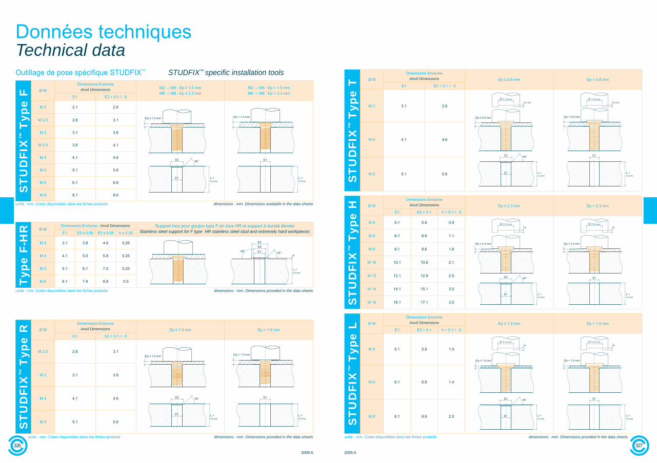
Cette valeur est représentative des effortsappliqués après assemblage sur STUDFIX™.Les valeurs d’arrachement sont fournies dans les fi ches produits STUDFIX™.
This value represents the force applied afterSTUDFIX™ assembly.The push-out force values are provided in the STUDFIX™ data sheets.
Effort d'arrachement Tensile force
Cette valeur est représentative de la tenue du composant avant assemblage.Les valeurs de dessertissage sont fournies dans les fi ches produits STUDFIX™.
This value represents component resistancebefore assembly.The push-out force values are provided in theSTUDFIX™ data sheets.
Effort de dessertissage Push-out force
Cette valeur est représentative de la tenueau dévissage après vieillissement.
This value is representative of resistance tounscrewing after ageing.
Tenue au couple direct Direct torque resistance
Dans la plupart des cas, la tenue au coupleindirect est supérieure (voire très supérieure) aux valeurs de couples de serrage maximumpréconisés pour des écrous de classe 8 aveccoeffi cient de frottement de 0.20.La valeur indiquée dans les fi ches produits a alors été limitée à la valeur de couple de serragemaximum préconisé pour des écrous de classe 8 avec coeffi cient de frottement de 0.20.Dans les autres cas, la valeur indiquée dans les fi ches produits correspond à la valeur de serrage préconisée compatible avec la tenue au coupleindirect de STUDFIX™.
In most cases, indirect torque resistance is higher (even much higher) than recommended maximumtightening torque for grade 8 nuts with a friction coeffi cient of 0.20.The value shown in the data sheets has thereforebeen limited to the recommended maximumtightening torque for grade 8 nuts with a friction coeffi cient of 0.20.In other cases, the value shown in the data sheets corresponds to the recommended torque value that is compatible with STUDFIX™ indirect torque resistance.
Tenue au couple indirect Indirect torque resistance
Données techniquesTechnical data
328
ST
UD
FIX
™ T
ype
P Ø MDimensions Enclume
Anvil Dimensions Ep ≤ 1.7 mm Ep > 1.7 mmE1 E2 + 0.1 / - 0
Ø 3 3.1 3.9
Ø 4 4.1 4.9
Ø 5 5.1 5.9
Ø 6 6.1 6.9
unité : mm. Cotes disponibles dans les fi ches produits dimensions : mm. Dimensions provided in data sheets
Typ
e F
Liss
e / U
nthr
eade
d Ø MDimensions Enclume
Anvil Dimensions Ep ≤ 1.7 mm Ep > 1.7 mmE1 E2 + 0.1 / - 0
Ø 3 3.6 4.1
Ø 4 4.1 4.6
Ø 5 5.6 6.1
Ø 6 6.1 6.6
unité : mm. Cotes disponibles dans les fi ches produits dimensions : mm. Dimensions provided in data sheets
Coeffi cient de frottementFriction coeffi cient M 3 M 4 M 5 M 6 M 8 M10 M 12 M 14 M 16
0.20 1.4 3.2 6.4 11.1 27 53 92 148 232
0.15 1.2 2.8 5.5 9.5 23 46 79 127 198
0.10 0.9 2.2 4.3 7.5 18.2 36 62 99 153
Serrage maximum préconisé (N.m)Recommended maximum tightening
torque (N.m)
NF E25-030(écrous de classe 8) / (grade 8 nuts)
Inox : la gamme STUDFIX™ inox est réalisée à partir d’un inox austénitique. Ce matériau est reconnu pour son effi cacité enambiance corrosive.
Inox HR : La résistance mécanique des composants en inox HR facilite et autorise le sertissage sur supports à dureté trèsélevée (jusqu'à 90 HRB). La gamme HR représente donc la solutionoptimale sur le plan mécanique pour les sertissages inox sur inox.
Stainless steel: The STUDFIX™ stainless steel range isproduced using austenitic stainless steel. This material isrecognised for its effectiveness in corrosive environments.
HR Stainless steel: The mechanical resistance of thecomponents facilitates and permits crimping on extremely hard workpieces (up to 90 HRB). The HR range is therefore the optimal solution, in mechanical terms, for stainless steel to stainless steel crimping.
Nuances d'inox Stainless steel grades
Pour des environnements très sévères et des applicationsspécifi ques, LA CLUSIENNE-CLUFIX propose des produits sur mesure à très haute résistance à la corrosion.
For extremely harsh environments and specifi c applications, LA CLUSIENNE-CLUFIX offers custom-made products that areextremely resistant to corrosion.
Les valeurs correspondantes à ces essais peuvent varier en fonction des matériaux et des conditions de mise en oeuvre. Il est recommandé deprocéder à des essais dans les conditions réelles d'application.
Data related to those tests is provided as a guideline only. These values may vary in accordance with the materials used and implementationconditions. It is recommended that tests be conducted in the actual application conditions.