
Normal Strain and Stress Normal Strain and Stress, Stress strain diagram, Hooke’s Law 1.
Upload
clara-terryCategory
view
216download
1
Stress and strain measurement
Done by:
Ahmad Al-Ameen Osaid J. Matar

Definition of stress and strain. Tensile test theory (experiment to find
stress and strain). Clip on extensometers.
Linear variable differential transformer (LVDT) Strain gage.
Non-contact extensometers .• Non-contact laser extensometer.• Non-contact video extensometer.
Summary. References.
Main subjects in presentation:
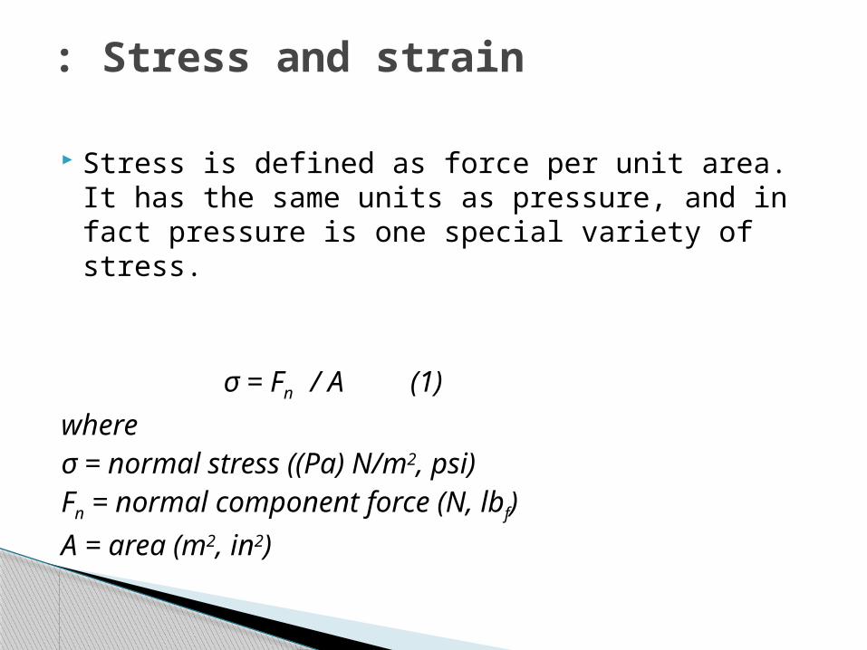
Stress is defined as force per unit area. It has the same units as pressure, and in fact pressure is one special variety of stress.
σ = Fn / A (1)
whereσ = normal stress ((Pa) N/m2, psi)Fn = normal component force (N, lbf)
A = area (m2, in2)
Stress and strain:

Strain is defined as the amount of deformation an object experiences compared to its original size and shape, Note that strain is dimensionless.
ε = dl / lo = σ / E (2)
wheredl = change of length (m, in)lo = initial length (m, in)
ε = unitless measure of engineering strainE = Young's modulus (Modulus of Elasticity) (Pa,
psi)
Stress and strain

Robert Hooke found that, when the forces are not too large (less than the yield force), the amount of strain experience by an object was directly proportional to the stress.
From Hooke's law.
Stress and strain

Objective:-
To determine the strength and several elastic and plastic property of some material.
To do the tensile test. To observe the behavior of material under
static load and to study fracture. To take a good information about the
machine and how to use it .
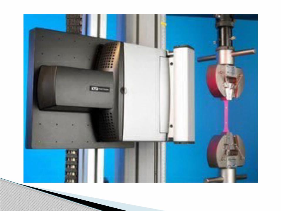
Tensile test:

If the load is divided by the original cross-section area and the elongation is divided by the original gauge length, the size effects are eliminated and the plot becomes known as an engineering (Stress-Strain) diagram,
Stress= σ =P/AoStrain= ε =∆L/Lo
Theory:

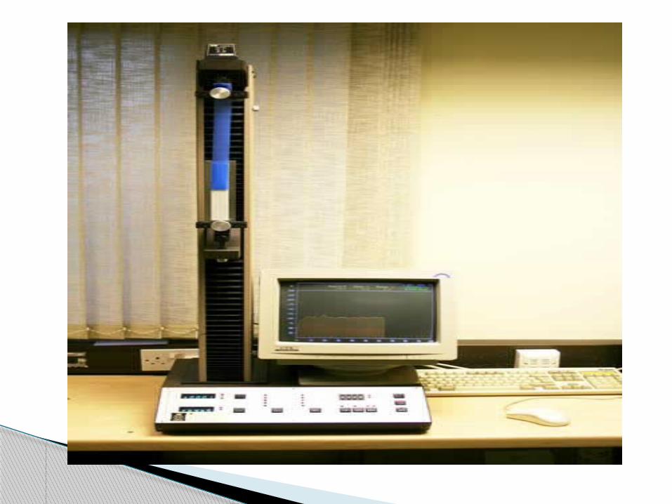
Tensile test machine (Tensometer):- It is a machine used to determine the
strength and several elastic and plastic properties of various materials; the test specimen is installed between two large grips of testing machine and then loaded in tension.
Apparatus:

Tensile test specimen:- The ends of specimen are enlarged where
they fit in the grips so that the failure will not occur near the grips themselves.
A failure at the ends will not produce the
desired information about the material because the stress distribution in uniform and the bar is subjected only to pure-tension.

Experimental results:

Theoretical result:

Source of uncertainties:- uncertainty in measuring the dimension of
specimen. The material itself. The temperature effects. The crack in the specimen.
Source of uncertainties

TENSILE TESTS are performed for several reasons.
•The results of tensile tests are used in selecting materials for engineering applications. •Tensile properties frequently are included in material specifications to ensure quality. •Tensile properties often are measured during development of new materials and processes, so that different materials and processes can be compared.• Finally, tensile properties often are used to predict the behavior of a material under forms of loading other than uniaxial tension.

Clip on extensometer: Linear variable differential transformer device (LVDT). Strain gage.
Non-contact laser extensometer. Parallel scanner. Cross scanner. Laser Doppler scanner. Biax scanner. Double beam cross scanner.
Non-contact video extensometer.
Extensometer types:

Stress –Strain Measurements by Extensometers:-
The elongation of a specimen during load application can be measured directly with various types of devices, such as clip-on extensometers ,directly-mounted strain gages and various optical devices.Selection of a device for strain measurement depends on various factors: 1- The useable range of the Extensometer .
2- Techniques for mounting the Extensometer.
3- Specimen size .
4- Environmental test conditions.
5- Electronic circuit configuration and analysis for signal processing.


•Clip-on extensometers
•It can be attached to a test specimen to measure elongation or strain as the load is applied. •This is usually used for metals and similar materials that exhibit high stiffness.
•Typical extensometers can measure for the gauge lengths such as 25 or 50 mm (1 or 2 in.).
•There also are transverse strain measuring devices that indicate the reduction in width or diameter as the specimen is tested.


The two basic types of clip-on extensometers are :-
1-Linear variable differential transformer (LVDT) devices
2- Strain-gage devices.

LVDT extensometers
•LVDT extensometers employ an LVDT with a core, which moves from specimen deformation and produces an electrical signal proportional to amount of core movement .
•LVDT extensometers are small, lightweight, and easy to use.
•They can be used on small specimens such as thread components ,and on large test specimens such as reinforcing bars, heavy steel plate, and tubing up to 75 mm (3 in.) in diameter.


Strain-gage Extensometer •A device which measures mechanical deformation. Which can convert a small mechanical motion to an electrical signal ,when a metal (wire or foil) or semiconductor is stretched, its resistance is increased.
•The strain gage attached to the beam is an electrically conductive small-sized grid that changes its resistance when deformed in tension, compression, bending, or torsion.

•Strain-gage Extensometer are also common and lighter in weight and smaller in size, but strain gages are somewhat more fragile than LVDTs.
•Thus, strain gages can be used to supply the information necessary to calculate strain, stress, angular torsion.
•These gages typically measure 9.5 to 13 mm ( 3/8 to 1 ⁄ 2 in.) in width and 13 to 19 mm ( 1 ⁄ 2 to 3 ⁄ 4 in.) in length.

How does the Strain Gauge work?
•Operation of strain-gage extensometers is based on gages that are bonded to a metallic element and connected to a bridge circuit. •Deflection of the element, due to specimen strain, changes the gage’s resistance that produces an output signal from a bridge circuit.
•This signal is amplified and processed by signal conditioners before being displayed on a digital readout, chart recorder, or computer.
•Foil strain gages currently are the most widely used, due to the ease of their attachment

Test specimen with bonded resistance strain gages and a 25 mm (1 in.) gage length.

Calibration, Classification, and Verification of Extensometers.
•All types of extensometers for materials testing must be verified, classified, and calibrated in accordance with applicable standards.
• Calibration of extensometers refers to the procedure of determining the magnitude of uncertainty in strain measurements.
•Several calibration devices can be used, including an interferometer, calibrated standard gage blocks and an indicator, and a micrometer.

•Verification is a calibration to ascertain whether the errors are within a predetermined range.
•Verification also implies certification that an extensometer meets stated accuracy requirements, which are defined by classifications such as those in ASTM.

Non-contact extensometer:
Laser extensometer .• parallel scanner .• Stereo angle scanner.• Cross scanner.• Laser Doppler scanner.• Biax scanner.• Double beam parallel scanner.
Video extensometer.

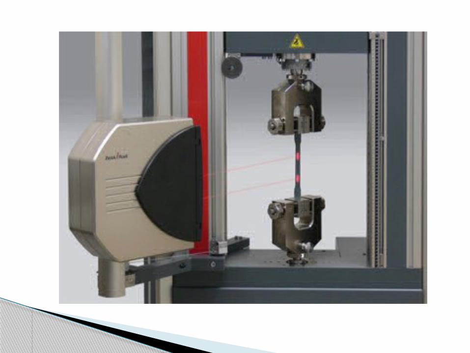
Non contact extensometers (video and laser scanning)
The main advantage of non-contact video and laser scanning extensometers is that they can be used up to break without damage even when testing specimens that exhibit whiplash. They require measurement marks to be attached to the specimen which are optically distinct from the surrounding area of the specimen.

The measurement marks are clipped, tacked, or glued onto the specimen, or the specimen is marked with a colored pen. In every case, this introduces additional sources of error as the marks can become indistinct, move, or fall off the specimen surface as it deforms during loading. The application of the measurement marks is also an additional process by the operator and can introduce higher costs as well as inaccuracies to the test results.

Laser extensometer
Scanning Laser Extensometers for measuring deformation at static, quasistatic and cyclic loading
Parallel Scannerhigh resolution and accuracy, insensitive to small variations of the working distance Stereo Angular Scannermeasurement of large strain, scanning range up to 500 mm Cross Scannersimultaneous measurement of longitudinal and lateral strain, determination of Poisson's ratio

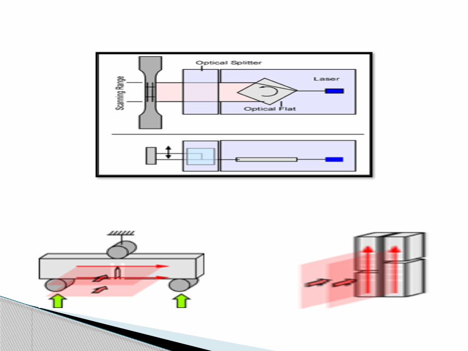
The laser extensometer - type parallel scanner is used for non-contact measurement of strain or compression of specimen at uniaxial load. Before starting the experiment, two marks are put on the sample. A laser beam is directed onto a rotating optical flat. During entering and leaving the laser beam is refracted at two opposite planes of the optical flat which results in an identical refractive angle. By the rotation of the optical flat, the laser beam is deflected in parallel to itself and is directed onto the specimen. The laser extensometer scans the measuring range with a visible laser beam. After automatically determining the reference length at the beginning, the positions of the marks are continuously observed throughout the experiment
Parallel Scanner

Technical Data P-50 P-100 P-130
Scan Range on Specimen
50 mm 100 mm 130 mm
Working Distance
100..300 mm 100..300 mm100..300
mm
Resolution (micron)
0.1 um 0.25 um 0.3 um
Accuracy (DIN EN 10002-4) Class 0.2; 0.5; 1 Class 0.5; 1 Class 0.5;
1
Scanning Rate 50 ;200 Hz 50 ;200 Hz 50 ;200 Hz
Duration of each Scan at Specimen
5.0 ms 5.0 ms 5.0 ms
Scan Speed On Specimen
10 m/s 20 m/s 27 m/s
Specimen Surface
plane orstructured
(components)
plane orstructured
(components)
plane orstructure
d(compone
nts)

Stereo Angular Scanner:
The SWS-300 is a deformation meter for all materials. Its high accuracy allows non-contact strain control from elasticity range till breaking elongation. The surface of the specimen is scanned by a laser beam. A set of stripes applied to the surface reflects the laser light. The receiver evaluates the reflected light and changes the signals into digital impulses. The positions of stripes and the measured length are determined from the time process of the signals. A novel deflection system allows the SWS-300 to measure changes in distance between specimen and scanner.

Advantages•highest precision up to a big measuring area of 300mm •accuracy class (1 (referring to DIN EN ISO 9513 .•non-contact measurement with measuring marks •no influence of specimen by extensometer •easy integration in testing machine software •measurement of pressure tests and bending tests •measurement from smallest to big strains •determination of E-module without additional receiver or rebuilding •measurement of changes in distance between specimen and SWS-300

Optional extensions
The whole experimental run is traceable on screen strain-regulated experiments are possible local dissolving at measurement of breaking elongation at welds and assembling componentsforce recording with evaluation software for calculation of characteristic valuesapplicable to climatic chambers

Technical Data SWS-300
measuring range 300 mm
accuracy class (DIN EN ISO 9513)
1
resolution 1 μm
lowest measuring length 2 mm
working distance (scanner<>specimen)
250 mm
scanning rate 100 Hz
number of stripes 2 / optional locally resolved
Laser safety class2 M (no additional protective
arrangements necessary)
dimensions/weight310 mm x 240 mm x 250 mm /
8 kg

Cross Scanner
The laser extensometer - type cross-scanner is used for simultaneous contact free measurement of longitudinal and lateral strain of specimens at uniaxial load. This scanner type is optimised for determining Possion's ratio.. Before starting the experiment, two marks for longitutinal strain and two marks for lateral strain are put on the sample. One laser beam for each measuring direction is directed onto rotating optical flats. During entering and leaving the laser beam is refracted at two opposite planes of the optical flat which results in an identical refractive angle. By the rotation of the optical flat, the laser beam is deflected in parallel to itself and is directed onto the specimen. The laser extensometer scans the measuring range with a visible laser beam. After automatically determining the reference length at the beginning, the positions of the marks are continuously observed throughout the experiment.

Cross scanner:

Technical Data K-50 K-100 K-130
Working Distance 100-300 mm 100-300 mm100-300 mm
Scan Range on Specimen 50 mm 100 mm 130 mm
Resolution (micron) 0.1 um 0.25 um 0.3 umAccuracy (DIN EN 10002-4)
Class 0.2; 0.5; 1
Class 0.5; 1
Class 0.5; 1
Scanning Rate 50 ;100 Hz 50 ;100 Hz50 ;100
HzDuration of each Scan at Specimen
5.0 ms 5.0 ms 5.0 ms
Scanning Speed at Specimen
10 m/s 20 m/s 27 m/s

Lateral Strain
Scan Range on Specimen
50 mm 50 mm 50 mm
Resolution (micron) 0.1 um 0.1 um 0.1 um
Accuracy (DIN EN 10002-4) Class 0.5 Class 0.5 Class 0.5
Scanning Rate 50 ;100 Hz 50 ;100 Hz 50 ;100 Hz
Duration of each Scan at Specimen
5.0 ms 5.0 ms 5.0 ms
Scanning Speed at Specimen
10 m/s 10 m/s 10 m/s
Specimen Surface
plane orstructured(Components)
plane orstructured(Components)
plane orstructured(Components)

Laser Doppler Extensometer
The Laser Doppler Extensometer is typically used at high speed tensile tests with deformation speed up to 50 m/s. Based on the high resolution in strain and time of our system, even the elastic range can be analyzed with a reasonable amount of data points (5000 points with an aluminum alloy at 10 m/s). The strain is measured directly at the sample. Because of the contact free and therefore non intrusive measuring principle, the samples are not influenced by the measuring equipment. Furthermore the Laser Doppler Extensometer is not endangered during the experiment and at rupture of the sample.

Technical Data
Measurement Length on Sample
any
Working Distance: 200 mm
Accuracy: 1%Sample Rate: up to 50 MHz
Deformation Speed:
0.01 .. 1 of vmax; vmax = 1 .. 50 m/sSeveral parameters are default
settings for a typical setup of a Laser Doppler Extensometer. Most of them can be chosen for the device to be
delivered .

Optical Clipon
The High Frequency Laser Extensometer (Optical Clipon) was developed for strain measurement at UHCF applications and optimized for determination of hysteresis loops and dynamic characteristics .

Technical Data
Measurement Range ±500 µm ±200 µm ±100 µm
Resolution 0.25 µm 0.1 µm 0.05 µm
Testing Frequency 1 - 1000 Hz
Sample Frequency 1 MHz
Measurement Length 5 mm - 100 mm

The laser extensometer - type biax-scanner is used for non-contact measurement of strain or compression of specimen at biaxial load. Two laser extensometers of the type parallel-scanner are combined to measure strain in X- and Y-direction. The scanning sequence of the two systems is synchronized to each other. A single receiver with special optical components is used for both scanners.
Biax Scanner

Technical Data B-50 B-100 B-130Scanning Range
on Specimen50 mm 100 mm 130 mm
Working Distance 250..400 mm 250..400 mm 250..400 mm
Resolution (micron)
0.1 um 0.25 um 0.3 um
Accuracy (DIN EN 10002-4) Class 0.2; 0.5; 1 Class 0.5; 1 Class 0.5; 1
Scanning Rate 50 ;100 Hz 50 ;100 Hz 50 ;100 Hz
Duration of each Scan at
Specimen5.0 ms 5.0 ms 5.0 ms
Scanning Speed at Specimen
10 m/s 20 m/s 27 m/s
Specimen Surface
plane orstructured
(components)
plane orstructured
(components)
plane orstructured
(components)

Double Beam Parallel Scanner
The laser extensometer P-50D is used for non-contact measurement of strain, compression, or motion of specimen along two scanning lines. A laser beam is directed onto a rotating optical flat. During entering and leaving the laser beam is refracted at two opposite planes of the optical flat which results in an identical refractive angle. By the rotation of the optical flat, the laser beam is deflected in parallel to itself and scans along the specimen. The P-50D includes an optical beam splitter which generates two scan lines. One scan line is fixed, the other is adjustable in horizontal position. The distance between the scan lines can be adjusted by the user between 0 and 20 mm - other ranges are available on request. The extensometer is optimized for experiments like shear strain, crack opening and bending tests

Technical Data P-50D
Scan Range on Specimen 50 mm
Distance between Scan Lines
0 - 20 mm
Working Distance 100..300 mm
Resolution (micron) 0.1 um
Accuracy (DIN EN 10002-4) Class 0.2; 0.5; 1
Scanning Rate 50 ;200 Hz
Duration of each Scan at Specimen
5.0 ms
Scanning Speed at Specimen
10 m/s
Specimen Surfaceplane or structured
(components)

Along with integrated software that facilitates setup and consistent calibration, advanced video extensometer (AVE) uses digital camera and real-time image processing to make strain measurements on material test samples.
Non-contact measurement design ensures extensometer has no influence on specimen, eliminating possibility of damage. Solid-state unit is available with 3 fields of view and transverse strain measurement capabilities.
Video Extensometer features non-contact measurement design-:

Contact type extensometers measure
extension extremely accurately and are very cost effective. However, clip-on extensometers require much more manual intervention and without care can introduce scatter in the test results.
Feeler arms extensometers offer extremely high accuracy, excellent repeatability, and ease of use due to fully automatic operation which includes the setting of variable gauge lengths.
Summary

Non contact extensometers are required when the specimen is sensitive to notching knife edges or when the extensometer might be damaged at specimen break. They are also still relatively expensive and time consuming to set up and calibrate especially when testing different specimen types.
In short, there is no such device as a universal extensometer. The large range of applications demands various devices with different functions and characteristics, and the extensometer must be selected for each application.

[1 ]Davis, J. R. (Editor). Tensile Testing (2nd Edition).Materials Park, OH, USA.
[2 ]http://www.fiedler-oe.de/en/index.html. [3 ]4 ASTM E 83-02 Standard Practice for Verification
and Classification of Extensometer System. [4] Anwander, M., Zagar, B.G., Weiss, B., and Weiss, H.,
‘‘Non-Contacting Strain Measurements at High Temperatures by the Digital Laser Speckle Technique,’’
Experimental Mechanics .
References:

The End