DOE-HDBK-1018/2-93; DOE Fundamentals Handbook … science part 2 - section 4.pdf · DEMINERALIZERS...
25
DEMINERALIZERS DOE-HDBK-1018/2-93 Miscellaneous Mechanical Components DEMINERALIZERS The cost of corrosion and radioactive contamination caused by poor water quality in nuclear facilities is enormous. Demineralizers are an intricate part of water quality control. The chemical theory of demineralizers is detailed in the Chemistry Fundamentals Handbook. This chapter will address the mechanics of how demineralizers operate. EO 1.11 STATE the purpose of a demineralizer. P u r po s e o f D e m in e r aliz e r s Dissolved impurities in power plant fluid systems generate corrosion problems and decrease efficiency due to fouled heat transfer surfaces. Demineralization of the water is one of the most practical and common methods available to remove these dissolved impurities. In the plant, demineralizers (also called ion-exchangers) are used to hold ion exchange resins and transport water through them. Ion exchangers are generally classified into two groups: single- bed ion exchangers and mixed-bed ion exchangers. D e m in e r aliz e r s A demineralizer is basically a cylindrical tank with connections at the top for water inlet and resin addition, and connections at the bottom for the water outlet. The resin can usually be changed through a connection at the bottom of the tank. The resin beads are kept in the demineralizer by upper and lower retention elements, which are strainers with a mesh size smaller then the resin beads. The water to be purified enters the top at a set flow rate and flows down through the resin beads, where the flow path causes a physical filter effect as well as a chemical ion exchange. Sin gle -Be d D e m in e r aliz e r s A single-bed demineralizer contains either cation or anion resin beads. In most cases, there are two, single-bed ion exchangers in series; the first is a cation bed and the second is an anion bed. Impurities in plant water are replaced with hydrogen ions in the cation bed and hydroxyl ions in the anion bed. The hydrogen ions and the hydroxyl ions then combine to form pure water. The Chemistry Handbook, Module 4, Principles of Water Treatment, addresses the chemistry of demineralizers in more detail. ME-05 Rev. 0 Page 24
Transcript of DOE-HDBK-1018/2-93; DOE Fundamentals Handbook … science part 2 - section 4.pdf · DEMINERALIZERS...

DEMINERALIZERS DOE-HDBK-1018/2-93 Miscellaneous Mechanical Components
DEMINERALIZERS
The cost of corrosion and radioactive contamination caused by poor water qualityin nuclear facilities is enormous. Demineralizers are an intricate part of waterquality control. The chemical theory of demineralizers is detailed in theChemistry Fundamentals Handbook. This chapter will address the mechanics ofhow demineralizers operate.
EO 1.11 STATE the purpose of a demineralizer.
Pur pose of Deminer alizer s
Dissolved impurities in power plant fluid systems generate corrosion problems and decreaseefficiency due to fouled heat transfer surfaces. Demineralization of the water is one of the mostpractical and common methods available to remove these dissolved impurities.
In the plant, demineralizers (also called ion-exchangers) are used to hold ion exchange resins andtransport water through them. Ion exchangers are generally classified into two groups: single-bed ion exchangers and mixed-bed ion exchangers.
Deminer alizer s
A demineralizer is basically a cylindrical tank with connections at the top for water inlet andresin addition, and connections at the bottom for the water outlet. The resin can usually bechanged through a connection at the bottom of the tank. The resin beads are kept in thedemineralizer by upper and lower retention elements, which are strainers with a mesh sizesmaller then the resin beads. The water to be purified enters the top at a set flow rate and flowsdown through the resin beads, where the flow path causes a physical filter effect as well as achemical ion exchange.
Single-Bed Deminer alizer s
A single-bed demineralizer contains either cation or anion resin beads. In most cases, there aretwo, single-bed ion exchangers in series; the first is a cation bed and the second is an anion bed.Impurities in plant water are replaced with hydrogen ions in the cation bed and hydroxyl ionsin the anion bed. The hydrogen ions and the hydroxyl ions then combine to form pure water.The Chemistry Handbook, Module 4, Principles of Water Treatment, addresses the chemistry ofdemineralizers in more detail.
ME-05 Rev. 0Page 24

Miscellaneous Mechanical Components DOE-HDBK-1018/2-93 DEMINERALIZERS
Figure 13 illustrates a single-bed demineralizer. When in use, water flows in through the inletto a distributor at the top of the tank. The water flows down through the resin bed and exits outthrough the outlet. A support screen at the bottom prevents the resin from being forced out ofthe demineralizer tank.
Single-Bed Regener ation
Figure 13 Single-Bed Demineralizer
The regeneration of a single-bed ion exchanger is a three-step process. The first step is abackwash, in which water is pumped into the bottom of the ion exchanger and up through theresin. This fluffs the resin and washes out any entrained particles. The backwash water goesout through the normal inlet distributor piping at the top of the tank, but the valves are set todirect the stream to a drain so that the backwashed particles can be pumped to a container forwaste disposal.
The second step is the actual regeneration step, which uses an acid solution for cation units andcaustic solution for anion units. The concentrated acid or caustic is diluted to approximately10% with water by opening the dilution water valve, and is then introduced through adistribution system immediately above the resin bed. The regenerating solution flows throughthe resin and out the bottom of the tank to the waste drain.
The final step is a rinsing process, which removes any excess regenerating solution. Water ispumped into the top of the tank, flows down through the resin bed and out at the bottom drain.
Rev. 0 ME-05Page 25

DEMINERALIZERS DOE-HDBK-1018/2-93 Miscellaneous Mechanical Components
To return the ion exchanger to service, the drain valve is closed, the outlet valve is opened, andthe ion exchanger is ready for service.
Single-bed demineralizers are usually regenerated "in place." The resins are not pumped out toanother location for regeneration. The regeneration process is the same for cation beds and foranion beds; only the regenerating solution is different. It is important to realize that if the ionexchanger has been exposed to radioactive materials, the backwash, regeneration, and rinsesolutions may be highly radioactive and must be treated as a radioactive waste.
Mix ed-Bed Deminer alizer
A mixed-bed demineralizer is a demineralizer in which the cation and anion resin beads aremixed together. In effect, it is equivalent to a number of two-step demineralizers in series. Ina mixed-bed demineralizer, more impurities are replaced by hydrogen and hydroxyl ions, andthe water that is produced is extremely pure. The conductivity of this water can often be lessthan 0.06 micromhos per centimeter.
Mix ed-Bed Regener ation
The mixed-bed demineralizer shown in Figure 14 is designed to be regenerated in place, but theprocess is more complicated than the regeneration of a single-bed ion exchanger. The steps inthe regeneration are shown in Figure 14.
Figure 14a shows the mixed-bed ion exchanger in the operating, or on-line mode. Water entersthrough a distribution header at the top and exits through the line at the bottom of the vessel.Regeneration causes the effluent water to increase in electrical conductivity.
The first regeneration step is backwash, as shown in Figure 14b. As in a single-bed unit,backwash water enters the vessel at the bottom and exits through the top to a drain. In additionto washing out entrained particles, the backwash water in a mixed-bed unit must also separatethe resins into cation and anion beds. The anion resin has a lower specific gravity than thecation resin; therefore, as the water flows through the bed, the lighter anion resin beads floatupward to the top. Thus, the mixed-bed becomes a split bed. The separation line between theanion bed at the top and the cation bed at the bottom is called the resin interface. Some resinscan be separated only when they are in the depleted state; other resins separate in either thedepleted form or the regenerated form.
The actual regeneration step is shown in Figure 14c. Dilution water is mixed with causticsolution and introduced at the top of the vessel, just above the anion bed. At the same time,dilution water is mixed with acid and introduced at the bottom of the vessel, below the cationbed. The flow rate of the caustic solution down to the resin interface is the same as the flow rateof the acid solution up to the resin interface. Both solutions are removed at the interface anddumped to a drain.
ME-05 Rev. 0Page 26

Miscellaneous Mechanical Components DOE-HDBK-1018/2-93 DEMINERALIZERS
Figure 14 Regeneration of a Mixed-Bed Demineralizer
Rev. 0 ME-05Page 27
DEMINERALIZERS DOE-HDBK-1018/2-93 Miscellaneous Mechanical Components
During the regeneration step, it is important to maintain the cation and anion resins at theirproper volume. If this is not done, the resin interface will not occur at the proper place in thevessel, and some resin will be exposed to the wrong regenerating solution. It is also importantto realize that if the ion exchanger has been involved with radioactive materials, both thebackwash and the regenerating solutions may be highly radioactive and must be treated as liquidradioactive waste.
The next step is the slow rinse step, shown in Figure 14d, in which the flow of dilution wateris continued, but the caustic and acid supplies are cut off. During this two-direction rinse, thelast of the regenerating solutions are flushed out of the two beds and into the interface drain.Rinsing from two directions at equal flow rates keeps the caustic solution from flowing downinto the cation resin and depleting it.
In the vent and partial drain step, illustrated in Figure 14e, the drain valve is opened, and someof the water is drained out of the vessel so that there will be space for the air that is needed tore-mix the resins. In the air mix step, (Figure 14f) air is usually supplied by a blower, whichforces air in through the line entering the bottom of the ion exchanger. The air mixes the resinbeads and then leaves through the vent in the top of the vessel. When the resin is mixed, it isdropped into position by slowly draining the water out of the interface drain while the air mixcontinues.
In the final rinse step, shown in Figure 14g, the air is turned off and the vessel is refilled withwater that is pumped in through the top. The resin is rinsed by running water through the vesselfrom top to bottom and out the drain, until a low conductivity reading indicates that the ionexchanger is ready to return to service.
Exter nal Regener ation
Some mixed-bed demineralizers are designed to be regenerated externally, with the resins beingremoved from the vessel, regenerated, and then replaced. With this type of demineralizer, thefirst step is to sluice the mixed bed with water (sometimes assisted by air pressure) to a cationtank in a regeneration facility. The resins are backwashed in this tank to remove suspendedsolids and to separate the resins. The anion resins are then sluiced to an anion tank. The twobatches of separated resins are regenerated by the same techniques used for single-bed ionexchangers. They are then sluiced into a holding tank where air is used to remix them. Themixed, regenerated, resins are then sluiced back to the demineralizer.
External regeneration is typically used for groups of condensate demineralizers. Having onecentral regeneration facility reduces the complexity and cost of installing several demineralizers.External regeneration also allows keeping a spare bed of resins in a holding tank. Then, whena demineralizer needs to be regenerated, it is out of service only for the time required to sluiceout the depleted bed and sluice a fresh bed in from the holding tank. A central regenerationfacility may also include an ultrasonic cleaner that can remove the tightly adherent coating ofdirt or iron oxide that often forms on resin beads. This ultrasonic cleaning reduces the need forchemical regeneration.
ME-05 Rev. 0Page 28

Miscellaneous Mechanical Components DOE-HDBK-1018/2-93 DEMINERALIZERS
Summary
The important information in this chapter is summarized below.
Demineralizers Summary
Demineralization of water is one of the most practical and commonmethods used to remove dissolved contaminates. Dissolved impuritiesin power plant fluid systems can generate corrosion problems anddecrease efficiency due to fouled heat transfer surfaces. Demineralizers(also called ion-exchangers) are used to hold ion exchange resins andtransport water through them. Ion exchangers are generally classifiedinto two groups: single-bed ion exchangers and mixed-bed ionexchangers.
A demineralizer is basically a cylindrical tank with connections at thetop for water inlet and resin addition, and connections at the bottom forthe water outlet. The resin can usually be changed out through aconnection at the bottom of the tank. The resin beads are kept in thedemineralizer by upper and lower retention elements, which are strainerswith a mesh size smaller then the resin beads.
The water to be purified enters the top at a set flow rate, flows downthrough the resin beads where the flow path causes a physical filtereffect as well as a chemical ion exchange. The chemistry of the resinexchange is explained in detail in the Chemistry FundamentalsHandbook.
There are two types of demineralizers, single-bed and mixed-bed. Single-bed demineralizers have resin of either cation or anion exchangesites. Mixed-bed demineralizers contain both anion and cation resin.
All demineralizers will eventually be exhausted from use. To regenerate the resin and increase the demineralizer's efficiency, thedemineralizers are regenerated. The regeneration process is slightlydifferent for a mixed-bed demineralizer compared to the single-beddemineralizer. Both methods were explained in this chapter.
Rev. 0 ME-05Page 29

PRESSURIZERS DOE-HDBK-1018/2-93 Miscellaneous Mechanical Components
PRESSURIZERS
Pressurizers are used for reactor system pressure control. The pressurizer is thecomponent that allows a water system, such as the reactor coolant system in aPWR facility, to maintain high temperatures without boiling. The function ofpressurizers is discussed in this chapter.
EO 1.12 STATE the four purposes of a pressurizer.
EO 1.13 DEFINE the following terms attributable to a dynamicpressurizer system:
a. Spray nozzle c. Outsurgeb. Insurge d. Surge volume
I ntr oduction
There are two types of pressurizers: static and dynamic. A static pressurizer is a partially filledtank with a required amount of gas pressure trapped in the void area. A dynamic pressurizeris a tank in which its saturated environment is controlled through use of heaters (to controltemperature) and sprays (to control pressure).
This chapter focuses on the dynamic pressurizer. A dynamic pressurizer utilizes a controlledpressure containment to keep high temperature fluids from boiling, even when the systemundergoes abnormal fluctuations.
Before discussing the purpose, construction, and operation of a pressurizer, some preliminaryinformation about fluids will prove helpful.
The evaporation process is one in which a liquid is converted into a vapor at temperatures belowthe boiling point. All the molecules in the liquid are continuously in motion. The moleculesthat move most quickly possess the greatest amount of energy. This energy occasionally escapesfrom the surface of the liquid and moves into the atmosphere. When molecules move into theatmosphere, the molecules are in the gaseous, or vapor, state.
Liquids at a high temperature have more molecules escaping to the vapor state, because themolecules can escape only at higher speeds. If the liquid is in a closed container, the spaceabove the liquid becomes saturated with vapor molecules, although some of the molecules returnto the liquid state as they slow down. The return of a vapor to a liquid state is calledcondensation. When the amount of molecules that condense is equal to the amount of moleculesthat evaporate, there is a dynamic equilibrium between the liquid and the vapor.
ME-05 Rev. 0Page 30

Miscellaneous Mechanical Components DOE-HDBK-1018/2-93 PRESSURIZERS
Pressure exerted on the surface of a liquid by a vapor is called vapor pressure. Vapor pressureincreases with the temperature of the liquid until it reaches saturation pressure, at which timethe liquid boils. When a liquid evaporates, it loses its most energetic molecules, and the averageenergy per molecule in the system is lowered. This causes a reduction in the temperature of theliquid.
Boiling is the activity observed in a liquid when it changes from the liquid phase to the vaporphase through the addition of heat. The term saturated liquid is used for a liquid that exists atits boiling point. Water at 212oF and standard atmospheric pressure is an example of a saturatedliquid.
Saturated steam is steam at the same temperature and pressure as the water from which it wasformed. It is water, in the form of a saturated liquid, to which the latent heat of vaporizationhas been added. When heat is added to a saturated steam that is not in contact with liquid, itstemperature is increased and the steam is superheated. The temperature of superheated steam,expressed as degrees above saturation, is called degrees of superheat.
Gener al Descr iption
The pressurizer provides a point in the reactor system where liquid and vapor can be maintainedin equilibrium under saturated conditions, for control purposes. Although designs differ fromfacility to facility, a typical pressurizer is designed for a maximum of about 2500 psi and 680°F.
Dynamic Pr essur izer s
A dynamic pressurizer serves to:
maintain a system's pressure above its saturation point,
provide a means of controlling system fluid expansion and contraction,
provide a means of controlling a system's pressure, and
provide a means of removing dissolved gasses from the system by venting thevapor space of the pressurizer.
Constr uction
A dynamic pressurizer is constructed from a tank equipped with a heat source such as electricheaters at its base, a source of cool water, and a spray nozzle. A spray nozzle is a devicelocated in the top of the pressurizer that is used to atomize the incoming water.
Rev. 0 ME-05Page 31
PRESSURIZERS DOE-HDBK-1018/2-93 Miscellaneous Mechanical Components
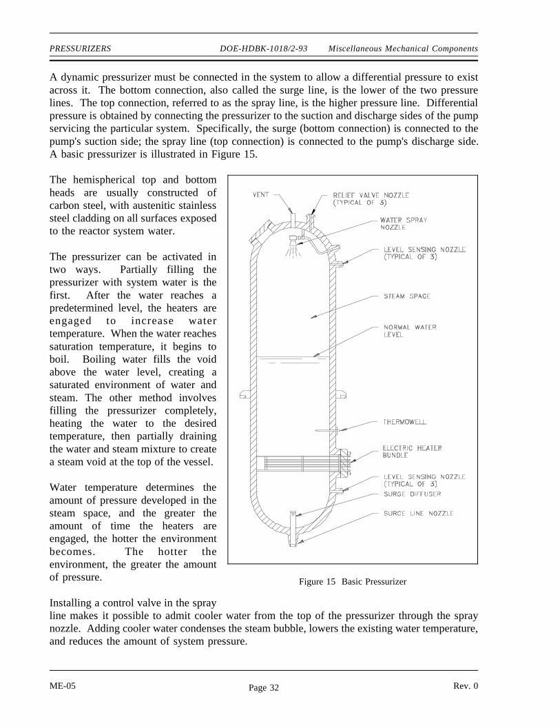
A dynamic pressurizer must be connected in the system to allow a differential pressure to existacross it. The bottom connection, also called the surge line, is the lower of the two pressurelines. The top connection, referred to as the spray line, is the higher pressure line. Differentialpressure is obtained by connecting the pressurizer to the suction and discharge sides of the pumpservicing the particular system. Specifically, the surge (bottom connection) is connected to thepump's suction side; the spray line (top connection) is connected to the pump's discharge side.A basic pressurizer is illustrated in Figure 15.
The hemispherical top and bottom
Figure 15 Basic Pressurizer
heads are usually constructed ofcarbon steel, with austenitic stainlesssteel cladding on all surfaces exposedto the reactor system water.
The pressurizer can be activated intwo ways. Partially filling thepressurizer with system water is thefirst. After the water reaches apredetermined level, the heaters areengaged to increase watertemperature. When the water reachessaturation temperature, it begins toboil. Boiling water fills the voidabove the water level, creating asaturated environment of water andsteam. The other method involvesfilling the pressurizer completely,heating the water to the desiredtemperature, then partially drainingthe water and steam mixture to createa steam void at the top of the vessel.
Water temperature determines theamount of pressure developed in thesteam space, and the greater theamount of time the heaters areengaged, the hotter the environmentbecomes. The hotter theenvironment, the greater the amountof pressure.
Installing a control valve in the sprayline makes it possible to admit cooler water from the top of the pressurizer through the spraynozzle. Adding cooler water condenses the steam bubble, lowers the existing water temperature,and reduces the amount of system pressure.
ME-05 Rev. 0Page 32
Miscellaneous Mechanical Components DOE-HDBK-1018/2-93 PRESSURIZERS
Oper ation
The level of water within a pressurizer is directly dependant upon the temperature, and thus thedensity, of the water in the system to which the pressurizer is connected. An increase in systemtemperature causes the density of the water to decrease. This decreased density causes the waterto expand, causing the level of water to increase in the vessel. The increased level of water ina pressurizer is referred to as an insurge. An insurge compresses the vapor space, which in turncauses the system pressure to rise. This results in slightly superheated steam in contact with thesubcooled pressurizer liquid. The superheated steam transfers heat to the liquid and to thepressurizer walls. This re-establishes and maintains the saturated condition.
A decrease in system temperature causes the density to increase which causes the system watervolume to contract. The contraction (drop) in pressurizer water level and increase in vapor spaceis referred to as an outsurge. The increase in vapor space causes the pressure to drop, flashingthe heated water volume and creating more steam. The increased amount of steam re-establishesthe saturated state. Flashing continues until the decrease in water level ceases and saturatedconditions are restored at a somewhat lower pressure.
In each case, the final conditions place the pressurizer level at a new value. The system pressureremains at approximately its previous value, with relatively small pressure variations during thelevel change, provided that the level changes are not too extreme.
In actual application, relying on saturation to handle all variations in pressure is not practical.In conditions where the system water is surging into the pressurizer faster than the pressurizercan accommodate for example, additional control is obtained by activating the spray. This spraycauses the steam to condense more rapidly, thereby controlling the magnitude of the pressurerise.
When a large outsurge occurs, the level can drop rapidly and the water cannot flash to steam fastenough. This results in a pressure drop. The installed heaters add energy to the water and causeit to flash to steam faster, thereby reducing the pressure drop. The heaters can also be left onto re-establish the original saturation temperature and pressure. In certain designs, pressurizerheaters are energized continuously to make up for heat losses to the environment.
The pressurizer's heater and spray capabilities are designed to compensate for the expected surgevolume. The surge volume is the volume that accommodates the expansion and contraction ofthe system, and is designed to be typical of normal pressurizer performance. Plant transients mayresult in larger than normal insurges and outsurges. When the surge volume is exceeded, thepressurizer may fail to maintain pressure within normal operating pressures.
Rev. 0 ME-05Page 33

PRESSURIZERS DOE-HDBK-1018/2-93 Miscellaneous Mechanical Components
Pressurizer operation, including spray and heater operation, is usually automatically controlled.Monitoring is required in the event the control features fail, because the effect on the systemcould be disastrous without operator action.
Summary
The important information in this chapter is summarized below.
Pressurizer Summary
Two types of pressurizers -- static and dynamic
Purposes of a pressurizer:
Maintains system pressure above saturation
Provides a surge volume for system expansion and contraction
Provides a means of controlling system pressure
Provides a means of removing dissolved gases
A spray nozzle is a device located in the top of the pressurizer, used to atomizeincoming water to increase the effects of spraying water into the top of thepressurizer to reduce pressure by condensing steam.
Insurge is the volume absorbed within the pressurizer during a level increase tocompensate for a rise in the system's temperature.
Outsurge is the volume released from the pressurizer during a level decrease tocompensate for a reduction in the system's temperature.
The surge volume is the volume of water that accommodates the expansion andcontraction of the system, and is designed to be typical of normal pressurizerperformance.
ME-05 Rev. 0Page 34

Miscellaneous Mechanical Components DOE-HDBK-1018/2-93 STEAM TRAPS
STEAM TRAPS
Steam traps are installed in steam lines to drain condensate from the lines withoutallowing the escape of steam. There are many designs of steam traps for highand low pressure use.
EO 1.14 STATE the purpose and general operation of a steam trap.
EO 1.15 IDENTIFY the following types of steam traps:
a. Ball float steam trap c. Bucket steam trapb. Bellow steam trap d. Impulse steam trap
Gener al Oper ation
In general, a steam trap consists of a
Figure 16 Ball Float Steam Trap
valve and a device or arrangement thatcauses the valve to open and close asnecessary to drain the condensate frompiping without allowing the escape ofsteam. Steam traps are installed at lowpoints in the system or machinery to bedrained. Some types of steam traps thatare used in DOE facilities are describedin this chapter.
Ball Float Steam T r ap
A ball float steam trap is illustrated inFigure 16. The valve of this trap isconnected to the float in such a way thatthe valve opens when the float rises.When the trap is in operation, the steamand any water that may be mixed with itflows into the float chamber. The water,being heavier than the steam, falls to the bottom of the trap, causing the water level to rise. Asthe water level rises, it lifts the float; thus lifting the valve plug and opening the valve. Thecondensate drains out and the float moves down to a lower position, closing the valve before thecondensate level gets low enough to allow steam to escape. The condensate that passes out ofthe trap is returned to the feed system.
Rev. 0 ME-05Page 35

STEAM TRAPS DOE-HDBK-1018/2-93 Miscellaneous Mechanical Components
Bucket Steam T r ap
Figure 17 Bucket Steam Trap
A bucket steam trap is illustrated inFigure 17. As condensate enters the trapbody, the bucket floats. The valve isconnected to the bucket in such a way thatthe valve closes as the bucket rises. Ascondensate continues to flow into the trapbody, the valve remains closed until thebucket is full. When the bucket is full, itsinks and thus opens the valve. Thevalve remains open until enoughcondensate has passed out to allow thebucket to float, and closing the valve.
Ther mostatic Steam T r aps
There are several kinds of thermostatic steam traps in use. In general, these traps are morecompact and have fewer moving parts than most mechanical steam traps.
Bellows-Type Steam T r ap
A bellows-type steam trap is illustrated in Figure 18. The operation of this trap is controlled bythe expansion of the vapor of a volatile liquid, which is enclosed in a bellows-type element.Steam enters the trap body and heats the volatile liquid in the sealed bellows, causing expansionof the bellows.
Figure 18 Bellows-Type Steam Trap
ME-05 Rev. 0Page 36

Miscellaneous Mechanical Components DOE-HDBK-1018/2-93 STEAM TRAPS
The valve is attached to the bellows in such a way that the valve closes when the bellowsexpands. The valve remains closed, trapping steam in the valve body. As the steam cools andcondenses, the bellows cools and contracts, thereby opening the valve and allowing thecondensate to drain.
I mpulse Steam T r ap
Impulse steam traps, illustrated in Figure 19, pass steam and condensate through a strainer beforeentering the trap. A circular baffle keeps the entering steam and condensate from impinging onthe cylinder or on the disk. The impulse type of steam trap is dependent on the principle thathot water under pressure tends to flash into steam when the pressure is reduced.
The only moving part in the steam trap is the disk. A flange near the top of the disk acts as a
Figure 19 Impulse Steam Trap
piston. As demonstrated in Figure 19, the working surface above the flange is larger than theworking surface below the flange.
Rev. 0 ME-05Page 37

STEAM TRAPS DOE-HDBK-1018/2-93 Miscellaneous Mechanical Components
A control orifice runs through the disk from top to bottom, which is considerably smaller at thetop than at the bottom. The bottom part of the disk extends through and beyond the orifice inthe seat. The upper part of the disk (including the flange) is inside a cylinder. The cylindertapers inward, so the amount of clearance between the flange and the cylinder varies accordingto the position of the valve. When the valve is open, the clearance is greater than when thevalve is closed.
When the trap is first placed in service, pressure from the inlet (chamber A) acts against theunderside of the flange and lifts the disk off the valve seat. Condensate is thus allowed to passout through the orifice in the seat; and, at the same time, a small amount of condensate (calledcontrol flow) flows up past the flange and into chamber B. The control flow discharges throughthe control orifice, into the outlet side of the trap, and the pressure in chamber B remains lowerthan the pressure in chamber A.
As the line warms up, the temperature of the condensate flowing through the trap increases. Thereverse taper of the cylinder varies the amount of flow around the flange until a balancedposition is reached in which the total force exerted above the flange is equal to the total forceexerted below the flange. It is important to note that there is still a pressure difference betweenchamber A and chamber B. The force is equalized because the effective area above the flangeis larger than the effective area below the flange. The difference in working area is such that thevalve maintains at an open, balanced, position when the pressure in chamber B is approximately86% of the pressure in chamber A.
As the temperature of the condensate approaches its boiling point, some of the control flowgoing to chamber B flashes into steam as it enters the low pressure area. Because the steam hasa much greater volume than the water from which it is generated, pressure builds up in the spaceabove the flange (chamber B). When the pressure in this space is 86% of the inlet pressure(chamber A), the force exerted on the top of the flange pushes the entire disk downward andcloses the valve. With the valve closed, the only flow through the trap is past the flange andthrough the control orifice. When the temperature of the condensate entering the trap dropsslightly, condensate enters chamber B without flashing into steam. Pressure in chamber B isthus reduced to the point where the valve opens and allows condensate to flow through theorifice in the valve seat. The cycle is repeated continuously.
With a normal condensate load, the valve opens and closes at frequent intervals, discharging asmall amount of condensate at each opening. With a heavy condensate load, the valve remainsopen and allows a continuous discharge of condensate.
Or if ice-Type Steam T r ap
DOE facilities may use continuous-flow steam traps of the orifice type in some constant servicesteam systems, oil-heating steam systems, ventilation preheaters, and other systems or servicesin which condensate forms at a fairly constant rate. Orifice-type steam traps are not suitable forservices in which the condensate formation is not continuous.
ME-05 Rev. 0Page 38

Miscellaneous Mechanical Components DOE-HDBK-1018/2-93 STEAM TRAPS
Although there are several variations of the orifice-type steam trap, each has one thing incommon; it contains no moving parts. One or more restricted passageways or orifices allowcondensate to trickle through, but do not allow steam to flow through. Some orifice-type steamtraps have baffles in addition to orifices.
Summary
The following important information in this chapter is summarized below.
Steam Traps Summary
A steam trap consists of a valve and a device or arrangement that causes the valveto open and close as necessary to drain the condensate from the lines withoutallowing the escape of steam. Steam traps are installed at low points in the systemor machinery to be drained.
The type of steam trap used depends primarily on its application. Types include ballfloat, bucket traps, thermostatic traps, bellows-type traps, impulse traps, and orifice-type traps.
Impulse steam traps pass steam and condensate through a strainer before entering thetrap. A circular baffle keeps the entering steam and condensate from impinging onthe cylinder or on the disk. The impulse type of steam trap is dependent on the factthat hot water under pressure tends to flash into steam when the pressure is reduced.
Rev. 0 ME-05Page 39

FILTERS AND STRAINERS DOE-HDBK-1018/2-93 Miscellaneous Mechanical Components
FILTERS AND STRAINERS
When it is necessary to remove suspended solids from a liquid, the usual methodis to filter or strain the liquid. The two methods differ only in the size of themesh being used. Filtering removes the very small solids, and straining removesthe larger solids. Because filtering and straining are for all practical purposesthe same, this chapter will differentiate the two terms on the basis of applicationof the filter or strainer.
EO 1.16 DESCRIBE each of the following types of strainers and filters,including an example of typical use.
a. Cartridge filters d. Bucket strainerb. Precoated filters e. Duplex strainerc. Deep-bed filters
EO 1.17 EXPLAIN the application and operation of a strainer or filterbackwash.
I ntr oduction
Filtration is a process used to remove suspended solids from a solution. Other processes suchas demineralization remove ions or dissolved ions. Different filters and strainers are used fordifferent applications. In general, the filter passage must be small enough to catch the suspendedsolids but large enough that the system can operate at normal system pressures and flows. Filtersand strainers are used throughout most DOE facilities. They are used in hydraulic systems, oilsystems, cooling systems, liquid waste disposal, water purification, and reactor coolant systems.
Cartr idge Filter s
Figure 20 illustrates a typical multi-cartridge filter. The cartridges are cylinders and usuallyconsist of a fiber yarn wound around a perforated metal core. The liquid being filtered is forcedthrough the yarn, which is approximately 1/2 inch thick, and then through the perforations in themetal core to the filter outlet, which can be at either end. A cartridge filter may include severalcartridges, the exact number depending on the liquid flow rate that must be handled.
ME-05 Rev. 0Page 40

Miscellaneous Mechanical Components DOE-HDBK-1018/2-93 FILTERS AND STRAINERS
In the filter assembly illustrated in Figure 21, the cartridges are held between plates so that the
Figure 20 Typical Multi-Cartridge Filter
water must pass through the layer of yarn to reach the filter outlet. The type of yarn that is useddepends on the application. Some of the fibers commonly used include resin-impregnated woolor cellulose, cotton-viscose, polypropylene, nylon, and glass. In some applications that involvehigh temperatures or pressures, porous metal cartridges are used. These cartridges are usuallymade of 316 stainless steel, but inconel, monel, and nickel are also used.
Depending on the fiber or metal that is used,
Figure 21 Cartridge Filter
cartridges are available that will filter out allparticle matter down to a specified size. Forexample, a certain cartridge might bedesigned to remove all particles larger than10 microns, one micron, or even 0.1 micron.(A micron is 10-3 millimeters.)
Cartridge filters have the advantage of beingrelatively inexpensive to install and operate.Instruments measure the differential pressureacross these filters to let the operator knowwhen a filter is plugged and must bereplaced. When the cartridges are removedfrom radioactive systems, the radiation levelscan be very high. For this reason, the
cartridges may be withdrawn into a shielded cask for moving to a storage area or a solid wasteprocessing area. When the porous metal cartridges become plugged, they can be cleanedultrasonically and reused. When this is done, the cleaning solution becomes contaminated andmust be processed as liquid radioactive waste.
Rev. 0 ME-05Page 41

FILTERS AND STRAINERS DOE-HDBK-1018/2-93 Miscellaneous Mechanical Components
Another type of cartridge filter is the wafer, or disk filter. In this filter, disks are stacked toform a cartridge and placed down over a central perforated pipe. Each disk is typically 1/8 inchto 1/4 inch thick and made of cellulose or asbestos fibers.
Liquid that enters the disk filter moves up around the outside of the stack of disks, is forcedbetween the disks, travels through the perforations in the central pipe, and then leaves the filter.The filtering action takes place as the liquid is forced between the disks.
As with the smaller cartridges, if a disk filter is used to filter radioactive water, it may be veryradioactive when it is removed, and must be handled very carefully. One way to remove a diskfilter is by means of a crane, which lifts the filter out of its housing and moves it to a shieldedcontainer. The disposal problem is one of the major disadvantages of cartridge and disk-cartridge filters.
Pr ecoat Filter s
A precoat filter eliminates the problem of physically handling radioactive materials, because thefilter material (called the medium) can be installed and removed remotely. Inside the filterhousing is a bundle of septums (vertical tubes, on which the filter medium is deposited). Theseptums in some filters are approximately 1 inch in diameter and 3 feet long and are usuallymade of perforated or porous metal (normally stainless steel). There may be several hundredof these septums in a filter. Septums in other filters are approximately 3 inches in diameter and3 feet long and are made of porous stone or porous ceramic material. There are usually lessthan 100 of these larger septums in a filter.
The filtering medium fibers may be finely divided diatomite, perlite, asbestos, or cellulose.Diatomite, the least expensive medium, is used to filter liquid waste that will be discharged fromthe plant. Cellulose is generally used for processing water that will be returned to a reactor,because diatomite can allow silica leaching.
When a precoat filter is in use, water that enters the filter vessel passes through the filtermedium that is deposited on the septums and then leaves through the outlet. Before the filtercan be placed into operation, however, the filter medium must be installed; that is, the filter mustbe precoated.
The first step in precoating the filter is to close the inlet and outlet valves to the filter. The filtermedium used is mixed with demineralized water in an external mixing tank to form a slurry,which is pumped through the filter. Some of the filter medium deposits on the septums and isheld there by the pressure of water on the outside of the septums. At the beginning of theprecoating process, some of the fibers of the filter medium pass through the septums, eitherbecause they are smaller than the openings or because they pass through lengthwise. Thus, thereis still some filter medium in the water as it leaves the filter, so the slurry is recirculated againand again until the water is clear. Clear water indicates that all of the filter medium is depositedon the septums, and the filter is precoated.
ME-05 Rev. 0Page 42

Miscellaneous Mechanical Components DOE-HDBK-1018/2-93 FILTERS AND STRAINERS
One characteristic of the precoating process is that a very even layer of filter medium(approximately 1/8 inch thick) is deposited on the septums. This occurs because the circulatingslurry follows the path of least resistance. When the coating at one point reaches a certainthickness, the slurry takes the fibers to another point, and this process continues until precoatingis complete.
Because water pressure holds the filter in place, flow must be maintained through therecirculating loop to keep the medium from falling off. This is called a holding flow. As theinlet and outlet valves are opened for normal usage, called service flow, the holding flow isgradually cut off.
Backwashing Pr ecoat Filter s
After a filter has been precoated, it is put into service and kept on line until the pressuredifferential indicates that the filter medium is becoming plugged. When this occurs, the old filtermedium is removed and the filter is precoated again. Filters are usually installed in pairs, so thatone filter can remain in service while the other is undergoing the filter backwashing andprecoating process.
Since water pressure helps to hold the filter medium against the septums, some of the old filtermedium will fall off as soon as this pressure is removed. Backwashing is used to remove thefilter medium that does not fall off. Backwashing is usually done in one of two ways. Withsome filters, demineralized water is pumped backwards through the center of the septums, andthe filter medium coating is knocked off by the water as it comes out through the septums.
Most filters use a multi-step backwashing procedure. First, the inlet valve and the outlet valveare closed, and the drain valve and the top vent are opened to allow the water to drain. Thenthe drain valve and the vent are closed, and the inlet water valve is opened to raise the waterlevel. The filter is equipped with a special high-domed top to trap and compress air. When thewater inlet valve is closed and the drain valve is opened quickly, the compressed air forces waterdown through the center of the septums. This water knocks the filter medium off of theseptums.
With both types of backwashing, the filter medium coating that is removed is sluiced out througha drain line to a filter sludge tank, where it is stored for further processing. The filter is thenprecoated again and put back into service.
With precoat filters, the type and quantity of filter medium is critical. If too little material ortoo coarse a material is used, some of the finely divided crud in the water may get into theopenings of the septums. When the filter is backwashed, this crud is usually not removed. Itcontinues to build up during subsequent use of the filter until the septums become so pluggedthat they have to be replaced.
Rev. 0 ME-05Page 43

FILTERS AND STRAINERS DOE-HDBK-1018/2-93 Miscellaneous Mechanical Components
If too much filter medium is used, the layer that builds up on the septums will bridge the areabetween the septums. When the filter is backwashed, these bridges are usually not removed.Therefore the bridging continues, and the filter runs become progressively shorter. Eventually,the filter must be opened and the filter medium must be removed manually.
Precoat filters are much more complicated than cartridge filters, and the equipment required ismuch more expensive to install and maintain. The major advantage of precoat filters is theremote operation, which eliminates the physical handling of highly radioactive filter cartridges.
Deep-Bed Filter s
Deep-bed filters are usually found only in makeup water systems, where they are used to filterwater after it has been treated in a clarifier. They are used to remove organic matter, chlorine,and very fine particulate matter.
A deep-bed filter is based on a support
Figure 22 Deep-Bed Filter
screen (decking), which is mounted afew inches above the bottom of thetank. The screen is perforated toallow water to flow through it. Acoarse, aggregate layer of crushed rockor large lumps of charcoal is placedon top of the screen, and the deep beditself (2 to 4 feet of granular anthraciteor charcoal) is placed on top of theaggregate. The filter is sized so thatthere is 1 to 2 feet of "free board"above the deep bed.
When the filter is in service, rawwater is pumped in through a pipe thatfeeds a distribution pipe above thedeep bed. The water is filtered as itpercolates down through the granules.(Charcoal granules will filter outorganic matter, chlorine, and fineparticulates, while anthracite granulesremove only the particulates.) Thewater collects in the bottom of thetank, below the support screen, andleaves the filter through a pipe in thebottom of the filter vessel.
ME-05 Rev. 0Page 44
Miscellaneous Mechanical Components DOE-HDBK-1018/2-93 FILTERS AND STRAINERS
Deep-bed filters, like precoat filters, are cleaned by backwashing. Water is pumped through thedistribution piping near the top of the filter. The flow rate of the water is kept high enough tolift the granulated charcoal or anthracite up into the free space. The water washes away thedeposits that have accumulated. When the backwash cycle is completed, the flow is stopped, andthe granules settle back down into the filter bed. The filter can then be put back into service.
Metal-Edged Filter s
Metal-edged filters are used in the lubrication (oil) systems of many auxiliary units. A metal-edged filter consists of a series of metal plates or disks. Turning a handle moves the plates ordisks across each other in a manner that removes any particles that have collected on the metalsurfaces. Some metal-edged type filters have magnets to aid in removing fine particles ofmagnetic materials.
Strainer s
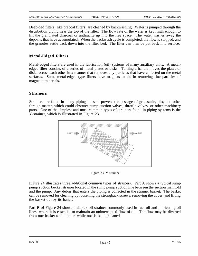
Strainers are fitted in many piping lines to prevent the passage of grit, scale, dirt, and otherforeign matter, which could obstruct pump suction valves, throttle valves, or other machineryparts. One of the simplest and most common types of strainers found in piping systems is theY-strainer, which is illustrated in Figure 23.
Figure 23 Y-strainer
Figure 24 illustrates three additional common types of strainers. Part A shows a typical sumppump suction bucket strainer located in the sump pump suction line between the suction manifoldand the pump. Any debris that enters the piping is collected in the strainer basket. The basketcan be removed for cleaning by loosening the strongback screws, removing the cover, and liftingthe basket out by its handle.
Part B of Figure 24 shows a duplex oil strainer commonly used in fuel oil and lubricating oillines, where it is essential to maintain an uninterrupted flow of oil. The flow may be divertedfrom one basket to the other, while one is being cleaned.
Rev. 0 ME-05Page 45

FILTERS AND STRAINERS DOE-HDBK-1018/2-93 Miscellaneous Mechanical Components
Part C of Figure 24 shows a manifold steam strainer. This type of strainer is desirable wherespace is limited, because it eliminates the use of separate strainers and their fittings. The coveris located so that the strainer basket can be removed for cleaning.
Backwashing
Figure 24 Common Strainers
If the filter or strainer cannot be easily removed for cleaning, the system design will usuallyinclude a flowpath for backwashing. The backwashing of precoated filters has already beenexplained because it is more complex than a typical backwash. The intent of a backwash is toflow liquid in the opposite direction of normal flow, creating a pressure that pushes the debrisoff the strainer or filter. The debris is flushed to a waste tank or drain.
Normally, to establish a backwash lineup, the flowpath upstream of the inlet to the strainer orfilter is closed, the flow path downstream of the outlet is closed, and a drain flowpath is opened.
ME-05 Rev. 0Page 46

Miscellaneous Mechanical Components DOE-HDBK-1018/2-93 FILTERS AND STRAINERS
The flush source is then opened and the flow goes into the outlet of the strainer or filter, throughthe strainer or filter, and exits the inlet to the backwash drain or waste tank, carrying the debriswith it.
Summary
The important information in this chapter is summarized below.
Filters and Strainers Summary
A cartridge filter may be a single cartridge or multi-cartridge filter. Thecartridges are cylinders that usually consist of a fiber yarn wound around aperforated metal core. The liquid being filtered is forced through the yarn andthen through the perforations in the metal core to the filter outlet, which can beat either end. This type of filter is used to remove fine particles in any flowcondition. Radioactive systems may use these because they are inexpensive andeasy to replace.
Precoat filters consists of a filter housing that contains a bundle of septums,(vertical tubes, on which the filter medium is deposited) usually made ofperforated or porous metal (normally stainless steel), porous stone, or porousceramic material. The filtering medium fibers may be finely divided diatomite,perlite, asbestos, or cellulose. Diatomite, the least expensive medium, is used tofilter liquid waste that will be discharged from the plant. Cellulose is generallyused for processing water that will be returned to the reactor, because diatomitecan allow silica leaching.
A deep-bed filter is based on a support screen (decking), which is mounted a fewinches above the bottom of the tank. The screen is perforated to allow water toflow through it. A coarse, aggregate layer of crushed rock or large lumps ofcharcoal is placed on top of the screen, and the deep bed itself (2 to 4 feet ofgranular anthracite or charcoal) is placed on top of the aggregate. This type offilter is frequently used in raw water treatment.
The bucket strainer is literally a bucket to catch debris. The bucket can beremoved for cleaning by loosening the strongback screws, removing the cover,and lifting the bucket out by its handle. It is usually used in systems expected tohave larger debris.
Rev. 0 ME-05Page 47

FILTERS AND STRAINERS DOE-HDBK-1018/2-93 Miscellaneous Mechanical Components
Filters and Strainers Summary (Cont.)
A duplex strainer is a strainer consisting of two sides with a basket in each side.Only one side is placed in service at a time. These are commonly used in fueloil and lubricating oil lines, where it is essential to maintain an uninterrupted flowof oil. The flow may be diverted from one basket to the other, while one is beingcleaned.
If the filter or strainer cannot be easily removed for cleaning, the system designwill usually include a flowpath for backwashing. The intent of a backwash is toflow liquid in the opposite direction of normal flow, creating a pressure thatpushes the debris off the strainer or filter. The debris is flushed to a waste tankor drain.
Normally, to establish a backwash lineup, the flowpath upstream of the inlet tothe strainer or filter is closed, the flow path down stream of the outlet is closed,and a drain flowpath is opened. The flush source is then opened and the flowgoes into the outlet of the strainer or filter, through the strainer or filter, and exitsthe inlet to the backwash drain or waste tank, carrying the debris with it.
end of text.
CONCLUDING MATERIAL
Review activities: Preparing activity:
DOE - ANL-W, BNL, EG&G Idaho, DOE - NE-73EG&G Mound, EG&G Rocky Flats, Project Number 6910-0024LLNL, LANL, MMES, ORAU, REECo,WHC, WINCO, WEMCO, and WSRC.
ME-05 Rev. 0Page 48