Documenting Process Calibrator - Fluke Corporationassets.fluke.com/manuals/74x_____cmeng0200.pdf74X...
44
® 74X Series Documenting Process Calibrator Calibration Manual PN 602505 February 1997 Rev. 2, 4/99 © 1997,1998,1999 Fluke Corporation, All rights reserved. Printed in U.S.A. All product names are trademarks of their respective companies.
Transcript of Documenting Process Calibrator - Fluke Corporationassets.fluke.com/manuals/74x_____cmeng0200.pdf74X...

®
74X SeriesDocumenting Process Calibrator
Calibration Manual
PN 602505February 1997 Rev. 2, 4/99© 1997,1998,1999 Fluke Corporation, All rights reserved. Printed in U.S.A.All product names are trademarks of their respective companies.


i
Table of Contents
Title PageIntroduction ......................................................................................................... 1Safety Information ............................................................................................... 1Specifications....................................................................................................... 3
DC Voltage Measurement ............................................................................... 3AC Voltage Measurement ............................................................................... 3DC Current Measurement................................................................................ 4Resistance Measurement ................................................................................. 4Continuity Testing........................................................................................... 4Frequency Measurement ................................................................................. 4DC Voltage Output.......................................................................................... 5DC Current Output .......................................................................................... 5Resistance Sourcing ........................................................................................ 5Frequency Sourcing......................................................................................... 6Temperature, Thermocouples.......................................................................... 6Temperature, Resistance Temperature Detectors ............................................ 8Loop Power Supply ......................................................................................... 9Top and Bottom Limits of Ranges with Auto Range On................................. 9
General Specifications ......................................................................................... 10Performance Verification Tests ........................................................................... 11
Equipment Required for Verification .............................................................. 11How to Verify.................................................................................................. 11
DC Volts Measurement............................................................................... 12AC Volts Measurement............................................................................... 14DC Current Measurement ........................................................................... 15Resistance Measurement ............................................................................. 16Frequency Measurement ............................................................................. 17DC Volts Source ......................................................................................... 18DC Current Source...................................................................................... 19Simulate Transmitter Function.................................................................... 20Frequency Source........................................................................................ 22Thermocouple Measure............................................................................... 23Thermocouple Source ................................................................................. 24RTD Measure, Four-Wire ........................................................................... 25RTD Measure, Three-Wire ......................................................................... 26RTD Source ................................................................................................ 27Loop Power................................................................................................. 28
74X SeriesCalibration Manual
ii
HART Mode Verification.................................................................................... 29Calibration ........................................................................................................... 30
Equipment Required for Calibration ............................................................... 30Calibration Status Indicator ............................................................................. 31Calibration Constant Out of Bounds ............................................................... 31Order of Calibration ........................................................................................ 31How to Calibrate ............................................................................................. 32
Adjustment of Potentiometers ............................................................................. 34Replaceable Parts................................................................................................. 35Service Centers .................................................................................................... 36

iii
List of Tables
Table Title Page
1. Definition of Symbols............................................................................................. 22. Equipment Required for Verification...................................................................... 113. DC Volts Measurement Verification Points............................................................ 134. AC Volts Measurement Verification Points............................................................ 145. DC Current Measurement Verification Points ........................................................ 156. Resistance Measurement Verification Points.......................................................... 167. Frequency Measurement Verification Points .......................................................... 178. DC Volts Source Verification Points ...................................................................... 189. DC Current Source Verification Points................................................................... 1910. Simulate Transmitter Verification Points................................................................ 2011. Resistance Source Verification Points .................................................................... 2112. Frequency Source Verification Points..................................................................... 2213. Temperature Measure Verification ......................................................................... 2314. Temperature Source Verification (Type-K Thermocouple, ITS-90)....................... 2415. RTD Measure Verification (100W Pt (385), Four-Wire Connection) .................... 2516. RTD Measure Verification (100W Pt (385), Three-Wire Connection)................... 2617. RTD Source Verification (100W Pt (385)) ............................................................. 2718. Loop Power Verification......................................................................................... 2819. Replacement Parts................................................................................................... 35

74X SeriesCalibration Manual
iv

v
List of Figures
Figure Title Page
1. LCD Operating Environment Specification ............................................................ 102. DC Volts and AC Volts Measurement Connections ............................................... 123. DC Current Measurement Verification Connections .............................................. 154. Resistance Measurement Verification Connections ................................................ 165. Frequency Measurement Verification Connections ................................................ 176. DC Volts Source Verification Connections ............................................................ 187. DC Current Source Verification Connections......................................................... 198. Simulate Transmitter Verification Connections...................................................... 209. Resistance Source Verification Connections........................................................... 2110. Frequency Source Verification Connections........................................................... 2211. Temperature Measure (TC) Verification Connections............................................ 2312. Four-Wire RTD Measure Verification Connections ............................................... 2513. Three-Wire RTD Measure Verification Connections ............................................. 2614. Loop Power Verification Connections .................................................................... 2815. HART Verification Connections............................................................................. 3016. Proper and Improper Jumper Use ........................................................................... 33

74X SeriesCalibration Manual
vi

1
IntroductionThis manual contains information necessary to perform performance verification testsand calibration adjustments on your Documenting Process Calibrator. General safetyinformation and product specifications are also included.
Unless stated otherwise, everything in this manual applies to the Fluke 741, 741B, 743,743B and 744 Documenting Process Calibrators, also referred to as the 74X Series in thismanual.
The phone number in the USA and Canada for replacement parts is: 1-888-993-5853.
To contact Fluke, call one of the following telephone numbers:
USA and Canada: 1-888-99-FLUKE(1-888-993-5853)
Europe: +31 402-678-200
Japan: +81-3-3434-0181
Singapore: +65-738-5655
Anywhere in the world: +1-425-356-5500
Or, visit Fluke’s Web site at www.fluke.com
Safety InformationThis calibrator is designed and tested in accordance with IEC1010-1 and CAN/CSAC22.2 No. 1010.1-92. Use the calibrator only as specified in this manual, otherwise theprotection provided by the calibrator may be impaired.
A Warning identifies conditions and actions that pose hazards to the user; a Cautionidentifies conditions and actions that may damage the calibrator or the equipment undertest.
Symbols used on the calibrator and in this manual are explained in Table 1. To protectyourself, follow these safety guidelines:
• Do not use the calibrator if it is damaged. Before you use the calibrator, inspect theinsulating cover. Look for cracks or missing plastic. Pay particular attention to theinsulation surrounding the connectors.
• Disconnect the power and discharge all high-voltage capacitors in the equipmentunder test before testing resistance or continuity.
• Inspect the test leads for damaged insulation or exposed metal. Check test leadcontinuity. Replace damaged test leads before using the calibrator.

74X SeriesCalibration Manual
2
• Do not use the calibrator if it operates abnormally. Protection may be impaired.When in doubt, have the calibrator serviced.
• Select the proper function and range for your measurement.
• Use caution when working above 30V ac rms, 42V ac pk, or 60V dc. Such voltagespose a shock hazard.
• When using the probes, keep your fingers away from the probe contacts. Keep yourfingers behind the finger guards on the probes.
• Connect the common test lead before you connect the live test lead. When youdisconnect test leads, disconnect the live test lead first.
• Do not operate the calibrator around explosive gas, vapor, or dust.
• When using a pressure module, make sure the process pressure line is shut off anddepressurized before you connect it to or disconnect it from the pressure module.
• Disconnect test leads before changing to another measure or source function.
• When servicing the calibrator, use only specified replacement parts.
Table 1. Definition of Symbols
AC-Alternating Current CAUTION see explanation
DC-Direct Current Common (LO) Input equipotentiality
FuseEquipment protected throughout by DOUBLEINSULATION or REINFORCED INSULATION
Pressure Conforms to relevant European Union directives
ON/OFFConforms to relevant Canadian StandardsAssociation directives
Recycling
Overvoltage (Installation) Category II per IEC 1010-1refers to the level of Impulse Withstand Voltageprotection provided. Typical locations include; MainsWall outlets, local appliances and PORTABLEEQUIPMENT

Specifications
3
SpecificationsAll specifications apply from +18 °C to +28 °C unless stated otherwise.
All specifications assume a 5 minute warmup period.
Measurement specifications are valid only when damping is turned on. When damping isturned off, or when the gö annunciator is displayed, floor specifications are multipliedby 3. Floor specifications are the second part of the specifications, usually expressed as"% of full scale." The measure pressure, temperature, and frequency functions arespecified only with damping on.
The standard specification intervals for the 74X Series is 1 and 2 years. Typical 90-daysource and measurement accuracy can be estimated by dividing the 1 year "% ofReading" or "% of Output" specifications by 2. Floor specifications, expressed as "% off.s.", remain constant.
To achieve the best noise rejection, use battery power and tie all three common jackstogether when performing DC and AC measurements.
DC Voltage Measurement
Range Resolution % of Reading +% of Full Scale
1 Year 2 Year
110 mV 1 µV 0.025% + 0.015% 0.05% + 0.015%
1.1V 10 µV 0.025% + 0.005% 0.05% + 0.005%
11V 100 µV 0.025% + 0.005% 0.05% + 0.005%
110V 1 mV 0.05% + 0.005% 0.1% + 0.005%
300V 10 mV 0.05% + 0.005% 0.1% + 0.005%
Temperature Coefficient: (0.001% of rdg. + 0.0015% f.s.)/ °C in the ranges -10 to 18 °C and 28 to 50 °CInput Impedance: 5 MΩCommon Mode Error: 0.008% f.s./(Common Mode Volt)Maximum Input Voltage: 300V rms
AC Voltage Measurement
Frequency Range % of Reading + Number of Counts
1 Year 2 Year
20 Hz to 40 Hz 2% + 10 2% + 10
40 Hz to 500 Hz 0.5% + 5 0.5% + 5
500 Hz to 1 kHz 2% + 10 2% + 10
1 kHz to 5 kHz 10% + 20 10% + 20
Ranges : 1.1000V, 11.000V, 110.00V, 300.0V rmsResolution: 11.000 counts in all ranges except 300V; 3,000 counts on 300V range.Input Impedance: 5 MΩ and <100 pFTemperature Coefficient: 10% of specification/ °C in the ranges -10 to 18 °C and 28 to 50 °CInput Coupling: acMaximum Input Voltage: 300 °V rmsMinimum Input Voltage: 0.5V above 1 kHz
Specifications apply for 10% to 100% of voltage range.

74X SeriesCalibration Manual
4
DC Current Measurement
Range Resolution % of Reading +% of Full Scale
1 Year 2 Year
30 mA 1 µA 0.01% + 0.015% 0.02% + 0.015%
110 mA 10 µA 0.01% + 0.015% 0.02% + 0.015%
Temperature Coefficient: (0.001% of rdg. + 0.002% f.s.)/ °C in the ranges -10 to 18 °C and 28 to 50 °CCommon Mode Error: 0.01% f.s./(Common Mode Volt)Maximum Input Voltage: 30V dc
Resistance Measurement
Range Resolution % of Reading + ohms
1 Year 2 Year
11Ω 0.001Ω 0.05% + 0.05 0.075% + 0.05
110Ω 0.01Ω 0.05% + 0.05 0.075% + 0.05
1.1 kΩ 0.1Ω 0.05% + 0.5 0.075% + 0.5
11 kΩ 1Ω 0.1% + 10 0.1% + 10
Temperature Coefficient: (0.01% f.s. + 2 mΩ) / °C in the ranges -10 to 18 °C and 28 to 50 °CCommon Mode Error: 0.005% f.s/(Common Mode Volt)Maximum Input Voltage: 30V dc
Continuity Testing
Tone Resistance
Continuous toneMay or may not get toneNo tone
<25Ω25 to 400Ω>400Ω
Frequency Measurement
Ranges Accuracy
1 Year 2 Year
1.00 Hz to 109.99 Hz 0.05 Hz 0.05 Hz
110.0 Hz to 1099.9 Hz 0.5 Hz 0.5 Hz
1.100 kHz to 10.999 kHz 0.005 kHz 0.005 kHz
11.00 kHz to 50.00 kHz 0.05 kHz 0.05 kHz
Minimum amplitude for frequency measurement (square wave):<1 kHz: 300 mV p-p1 kHz to 30 kHz: 1.4 V p-p>30 kHz: 2.8V p-p
Maximum Input:<1 kHz: 300V rms>1 kHz: 30V rms
Input Impedance: 5 MΩFor frequency measurement less than 109.99 Hz, specifications apply for signals with a slew rate greaterthan 5 volt/millisecond.

Specifications
5
DC Voltage Output
Range Resolution % of Output + % of Full Scale
1 Year 2 Year
110 mV 1 µV 0.01% + 0.005% 0.015% + 0.005%
1.1 V 10 µV 0.01% + 0.005% 0.015% + 0.005%
15 V 100 µV 0.01% + 0.005% 0.015% + 0.005%
Temperature Coefficient: (0.001% of output + 0.001% of f.s.)/ °C in the ranges -10 to 18 °C and 28 to 50°CMaximum Output Current: 10 mALoading: (0.001% f.s. + 1 µV)/ mACommon Mode Error: 0.008% f.s/(Common Mode Volt)Maximum Input Voltage: 30V dc
DC Current Output
Range/Mode Resolution % of Output + % of Full Scale
1 Year 2 Year
22 mA/ Source mA 1 µA 0.01% + 0.015% 0.02% + 0.015%
22 mA/ Simulate Transmitter(Current Sink)
1 µA 0.02% + 0.03% 0.02% + 0.03%
Maximum Burden Voltage: 24VTemperature Coefficient: (0.003% of output + 0.003% of f.s.)/ °C in the ranges -10 to 18 °C and 28 to50 °CCommon Mode Error: 0.008% f.s/(Common Mode Volt)Maximum Input Voltage: 30V dc
Specification applies for currents between 2 mA and 22 mA. For current below 2 mA, typical accuracy is0.15% of full scale.
Resistance Sourcing
Range Resolution % of Output + ohms
1 Year 2 Year
11.000Ω 1 mΩ 0.01% + 0.02 0.02% + 0.02
110.00Ω 10 mΩ 0.01% + 0.04 0.02% + 0.04
1.1000 kΩ 100 mΩ 0.02% + 0. 5 0.03% + 0.5
11.000 kΩ 1Ω 0.03% + 5 0.04% + 5
Temperature Coefficient: (0.01% of f.s.)/ °C in the ranges -10 to 18 °C and 28 to 50 °CMaximum and Minimum Current through Source Resistance:11Ω Range: 3 mA dc max, 0.1 mA dc min110Ω Range: 3 mA dc max, 0.1 mA dc min1.1 kΩ Range: 3 mA dc max, 0.01 mA dc min11 kΩ Range: 1 mA dc max, 0.01 mA dc minCommon Mode Error: 0.008% f.s/(Common Mode Volt)Maximum Input Voltage: 30V dc

74X SeriesCalibration Manual
6
Frequency SourcingRange Accuracy
0.00 Hz to 10.99 Hz 0.01 Hz
11.00 Hz to 109.99 Hz 0.1 Hz
110.0 Hz to 1099.9 Hz 0.1 Hz
1.100 kHz to 21.999 kHz 0.002 kHz
22.000 kHz to 50.000 kHz 0.005 kHz
Waveform Choices: Zero-symmetric sine or positive square wave, 50% duty cycleAmplitude: 0.1 to 10V p-pAmplitude Accuracy:
0 Hz to 1099 Hz: 3% of output + 0.5% f.s1.1 kHz to 10.9 kHz: 10% of output + 0.5% f.s11 kHz to 50 kHz: 30% of output + 0.5% f.s
Maximum Input Voltage: 30V dc
Temperature, ThermocouplesTemperature, TCs
Type Range °C Measure °C Source °C
1 Year 2 Year 1 Year 2 Year
E -250 to -200 1.3 2.0 0.6 0.9
-200 to -100 0.5 0.8 0.3 0.4
-100 to -600 0.5 0.8 0.3 0.4
600 to 1000 0.4 0.6 0.2 0.3
N -200 to -100 1.0 1.5 0.6 0.9
-100 to 900 0.5 0.8 0.5 0.8
900 to 1300 0.6 0.9 0.3 0.4
J -210 to -100 0.6 0.9 0.3 0.4
-100 to 800 0.3 0.4 0.2 0.3
800 to 1200 0.5 0.8 0.2 0.3
K -200 to -100 0.7 1.0 0.4 0.6
-100 to 400 0.3 0.4 0.3 0.4
400 to 1200 0.5 0.8 0.3 0.4
1200 to 1372 0.7 1.0 0.3 0.4
T -250 to -200 1.7 2.5 0.9 1.4
-200 to 0 0.6 0.9 0.4 0.6
0 to 400 0.3 0.4 0.3 0.4
B 600 to 800 1.3 2.0 1.0 1.5
800 to 1000 1.0 1.5 0.8 1.2
1000 to 1820 0.9 1.3 0.8 1.2

Specifications
7
Temperature, Thermocouples (cont.)Temperature, TCs
Type Range °C Measure °C Source °C
1 Year 2 Year 1 Year 2 Year
R -20 to 0 2.3 2.8 1.2 1.8
0 to 100 1.5 2.2 1.1 1.7
100 to 1767 1.0 1.5 0.9 1.4
S -20 to 0 2.3 2.8 1.2 1.8
0 to 200 1.5 2.1 1.1 1.7
200 to 1400 0.9 1.4 0.9 1.4
1400 to 1767 1.1 1.7 1.0 1.5
C 0 to 800 0.6 0.9 0.6 0.9
800 to 1200 0.8 1.2 0.7 1.0
1200 to 1800 1.1 1.6 0.9 1.4
1800 to 2316 2.0 3.0 1.3 2.0
L -200 to -100 0.6 0.9 0.3 0.4
-100 to 800 0.3 0.4 0.2 0.3
800 to 900 0.5 0.8 0.2 0.3
U -200 to 0 0.6 0.9 0.4 0.6
0 to 600 0.3 0.4 0.3 0.4
Sensor inaccuracies not included.
Accuracy with external cold junction; for internal junction add 0.2 °C
Resolution: 0.1 °C
Temperature Scale: ITS-90 or IPTS-68, selectable
Compensation: ITS-90 per NIST Monograph 175 for B,R,S,E,J,K,N,T; IPTS-68 per IEC 584-1 forB,R,S,E,J,K,T; IPTS-68 per DIN 43710 for L,U.
Temperature Coefficient: 0.05 °C/ °C in the range -10 to 18 °C and 28 to 50 °C
Common Mode Error: 0.01 °C/(Common Mode Volt)
Maximum Input Voltage: 30V
74X SeriesCalibration Manual
8
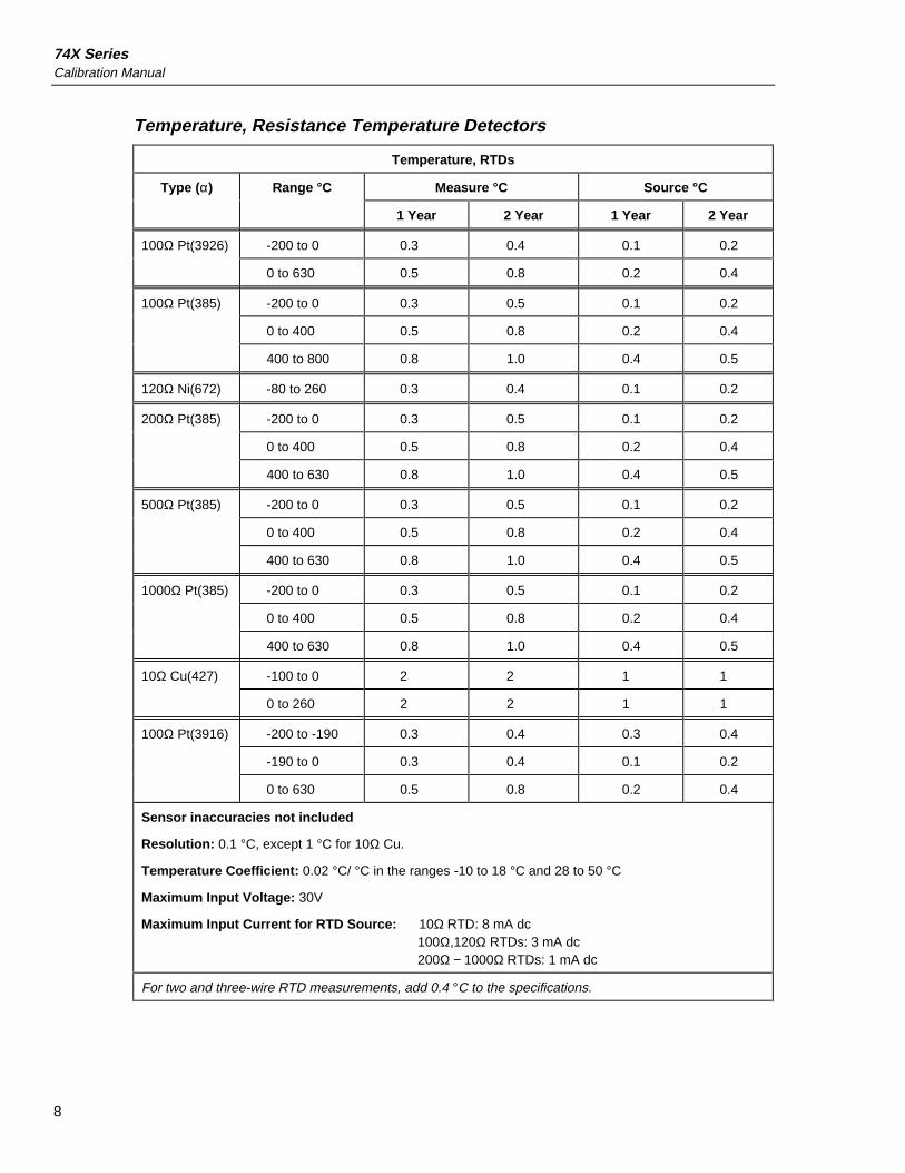
Temperature, Resistance Temperature Detectors
Temperature, RTDs
Type (α) Range °C Measure °C Source °C
1 Year 2 Year 1 Year 2 Year
100Ω Pt(3926) -200 to 0 0.3 0.4 0.1 0.2
0 to 630 0.5 0.8 0.2 0.4
100Ω Pt(385) -200 to 0 0.3 0.5 0.1 0.2
0 to 400 0.5 0.8 0.2 0.4
400 to 800 0.8 1.0 0.4 0.5
120Ω Ni(672) -80 to 260 0.3 0.4 0.1 0.2
200Ω Pt(385) -200 to 0 0.3 0.5 0.1 0.2
0 to 400 0.5 0.8 0.2 0.4
400 to 630 0.8 1.0 0.4 0.5
500Ω Pt(385) -200 to 0 0.3 0.5 0.1 0.2
0 to 400 0.5 0.8 0.2 0.4
400 to 630 0.8 1.0 0.4 0.5
1000Ω Pt(385) -200 to 0 0.3 0.5 0.1 0.2
0 to 400 0.5 0.8 0.2 0.4
400 to 630 0.8 1.0 0.4 0.5
10Ω Cu(427) -100 to 0 2 2 1 1
0 to 260 2 2 1 1
100Ω Pt(3916) -200 to -190 0.3 0.4 0.3 0.4
-190 to 0 0.3 0.4 0.1 0.2
0 to 630 0.5 0.8 0.2 0.4
Sensor inaccuracies not included
Resolution: 0.1 °C, except 1 °C for 10Ω Cu.
Temperature Coefficient: 0.02 °C/ °C in the ranges -10 to 18 °C and 28 to 50 °C
Maximum Input Voltage: 30V
Maximum Input Current for RTD Source: 10Ω RTD: 8 mA dc100Ω,120Ω RTDs: 3 mA dc200Ω − 1000Ω RTDs: 1 mA dc
For two and three-wire RTD measurements, add 0.4 °C to the specifications.

Specifications
9
Loop Power Supply
Setting 1 Year 2 Year
24 Volt 5% 5%
28 Volt 5% 5%
Short circuit protected
Maximum Current: 22 mA
Maximum Input Voltage: 30V dc
Top and Bottom Limits of Ranges with Auto Range On
Range, dc V Measure Top of Range Bottom of Range
110 mV ±110.000 mV 0.000 mV
1.1V ±1.10000V ±0.10000V
11V ±11.0000V ±1.0000V
110V ±110.000V ±10.000V
300V ±300.00V ±100.00V
Range, dc V Source
110 mV +110.000 mV -10.000 mV
1.1V +1.10000V +0.10000V
15V +15.000V +1.1000V
Range, ohms Measure and Source
11Ω 11.000Ω 0.000Ω
110Ω 110.00Ω 10.00Ω
1.1 kΩ 1100.0Ω 100.0Ω
11 kΩ 11.000 kΩ 1.000 kΩ
Range, Current Measure
22 mA +22.000 mA 0.000 mA
110 mA +110.00 mA +30.00 mA
Range, Current Source
22 mA +30.000 mA 0.000 mA
Range, Frequency Measure
100 Hz 109.99 Hz 1.00 Hz
1 kHz 1099.9 Hz 100.00 Hz
10 kHz 10.999 kHz 1.000 kHz
50 kHz 50.00 kHz 10.00 kHz

74X SeriesCalibration Manual
10
General SpecificationsDisplay: 240 by 200 pixel graphic LCD, 70 x 58 mm.
Power: Internal battery pack: NiCd, 7.2V, 1700 mAh.
Memory Backup: Lithium battery, 5 years typical lifetime.
Dimensions: 130 x 236 x 61 mm (5.1 x 9.3 x 2.4 in.).
Weight: 1.4 kg (3 lb. 1 oz.).
Altitude: Up to 2800 meters (9186 ft) above mean sea level.
Operating -10 to 50 °C (typically to -20 °C, except for frequency measure andTemperature: ac voltage measure).
Storage Temperature: -20 to 60 °C
Humidity: Avoid prolonged use outside the safe operating boundaries shown in thegraph on the next page.
RF Fields: Accuracy for all functions is not specified in RF fields >3 V/mAccuracy for thermocouple measurement is not specified in RF fields >1V/mAccuracy for ohms/RTD source is not specified in RF fields >0.5 V/mAccuracy for mADC measurement is not specified in RF fields >1.5 V/m
Safety: Designed in accordance with CAT II 300 Volts Pollution Degree 2, IEC1010-1, ANSI/ISA-S82, UL3111, and CSA C22.2 No. 1010.1-92. See“Safety Information” near the front of this manual.
Warranty: See the WARRANTY, inside front cover of the Users Manual.
100
90
80
70
60
50
40
30
20
10
0-20 0 20 40 60 80 100 120 140
Temperature (˚F)
Temperature (˚C)
%RH
-4
-20 0 30 40 50 60
= Normal Operation (-10˚C — 50˚C)
= Storage (-20˚C — 60˚C)+
14
-10
gb02f.eps
Figure 1. LCD Operating Environment Specification

Performance Verification Tests
11
Performance Verification TestsFluke recommends re-certification every year. To re-certify, perform the verificationprocedure. If any test points are out of tolerance, you need to calibrate, then re-verify.Two-year specifications are included for those customers who do not require the highestaccuracy.
The following tests verify compliance to specifications on the Documenting ProcessCalibrator.
Equipment Required for Verification
The equipment required for verification of the Documenting Process Calibrator is listedin the following table. If the recommended instruments are not available, you cansubstitute other source and measure instruments as long as they meet the minimum testrequirements.
Table 2. Equipment Required for Verification
Equipment Minimum Specification Recommended Model
Calibrator No substitute recommended Fluke 5500A
Frequency Counter 1Hz to 50kHz, 25ppm timebase Fluke PM6666
Oscilloscope 1Hz to 50 kHz (duty cycle accuracy1%)
Fluke 123
DMM No substitute recommended Hewlett Packard 3458A
Short jumpers (2) banana type Fluke PN 944632
Test leads (2 sets) banana to banana type Fluke TL20
Thermocouple miniplug polarize, with type-K thermocouplewelded to copper wire
see Figure 11
Lag bath characterized by a 0.1 °C standardthermometer (0.02 °C resolution)and a 1-pint thermos bottle
Princo ASTM-56C MercuryThermometer, Dewar Flask andCap
Smart (HART) Pressure Transmitter HART communication protocol Rosemount 1151 or 3051
HART Interface Cable Assembly No substitute recommended Fluke PN 689653
How to Verify
For each procedure there is a table of test points and acceptable readings. If the result ofthe test is outside the range shown, the Unit Under Test (UUT) is out of tolerance andshould be re-calibrated or repaired if necessary. There are separate columns for one andtwo-year specifications wherever the specifications differ.
Follow these general instructions for all the tests:
• For all tests, operate the UUT on battery power. Make sure the battery is fullycharged. Do not use the battery eliminator (BE9005).
• For measurement functions, press the [RANGE] button to lock the range on the rangespecified in the table of test points. The [RANGE] button may need to be pressedseveral times.

74X SeriesCalibration Manual
12
• Ranges in the specification tables include the 10% over-range capability. Rangenames on the 74X display do not include the 10% over-range. For example, the UUTdisplay shows Range 100 mV, but the range name in the table is 110 mV.
• Allow each item of verification equipment to satisfy its specified warm-up period.
• Allow at least 5 minutes for warm up.
• For each test, make sure the verification equipment has settled and that the"unsettled" annunciator on the UUT is not displayed.
DC Volts Measurement
Proceed as follows to verify the DC Volts Measurement function:
1. Connect the UUT to the 5500A as shown in Figure 2. Connect the three lows (blackinput jacks) with jumpers.
Caution Do not force a dual banana plug between any two jacks in the
horizontal orientation. Doing so will damage the jacks. Usethe supplied jumper wires (P/N 944632). You can use a dualbanana plug in the vertical orientation.
2. Set the UUT to the DC Volts Measurement function.
3. Press [RANGE] on the UUT to lock on the 110 mV range.
4. Set the 5500A to the first test point in Table 3.
5. Observe the reading on the UUT and check to see if it is within the range shownunder the appropriate column.
6. Continue through the test points, being careful to lock the UUT on the specifiedrange.
7. When you are finished, set the 5500A to [STANDBY].
TC
mA mA VVRTD
RTD
SOURCE 300VMAX30V
MAX30VMAX
30VMAX
MEASCAT
20V PK MAX
HI
LO
TC
TRIGOUT
1000V RMSMAX
20V RMSMAX
1V PKMAX
20V PK MAX
NORMAL AUX SCOPEV, ,RTD
A, -SENSE, AUX V
200V PK MAX
FLUKE 74X FLUKE 5500A CALIBRATOR
+_
gb03f.eps
Figure 2. DC Volts and AC Volts Measurement Connections

Performance Verification Tests
13
Table 3. DC Volts Measurement Verification Points
UUT
Range
Input
DCV
Minimum
1 Year
Maximum
1 Year
Minimum
2 Year
Maximum
2 Year
110mV 0 mV -0.017 0.017 -0.017 0.017
110mV 100 mV 99.959 100.042 99.934 100.067
110mV -100 mV -100.042 -99.959 -100.067 -99.934
1.1 V 0 mV -0.00006 0.00006 -0.00006 0.00006
1.1 V 1 V 0.99970 1.00031 0.99945 1.00056
1.1 V -1 V -1.00031 -0.99970 -1.00056 -0.99945
11 V 0 V -0.0006 0.0006 -0.0006 0.0006
11 V 10 V 9.9970 10.0031 9.9945 10.0056
11 V -10 V -10.0031 -9.9970 -10.0056 -9.9945
110V 0 mV -0.006 0.006 -0.006 0.006
110V 100 V 99.945 100.056 99.895 100.106
110V -100 V -100.056 -99.945 -100.106 -99.895
300V 0 mV -0.02 0.02 -0.02 0.02
300V 300 V 299.84 300.17 299.69 300.32
300V -300 V -300.17 -299.84 -300.32 -299.69

74X SeriesCalibration Manual
14
AC Volts Measurement
Proceed as follows to verify the AC Volts Measurement function:
1. Connect the UUT to the 5500A as shown in Figure 2. Connect the three lows (blackjacks) with jumpers.
2. Set the UUT to the AC Volts Measurement function.
3. Press [RANGE] on the UUT to lock on the 1.1V range.
4. Set the 5500A to the first test point in Table 4. Wait for the output to settle.
5. Observe the reading on the UUT and check to see if it is within the range shown.
6. Continue through the test points, being careful to lock the UUT on the specifiedrange.
7. When you are finished, set the 5500A to Standby.
Table 4. AC Volts Measurement Verification Points
UUTRange
Input(RMS)
Frequency Minimum 1 & 2 Year
Maximum 1 & 2 Year
1.1 V 0.2 V 500 Hz 0.1985 0.2015
1.1 V 1.0 V 20 Hz 0.9790 1.0210
1.1 V 1.0 V 40 Hz 0.9945 1.0055
1.1 V 1.0 V 500 Hz 0.9945 1.0055
1.1 V 1.0 V 1 kHz 0.9790 1.0210
1.1 V 1.0 V 5 kHz 0.8980 1.1020
11 V 2.0 V 500 Hz 1.985 2.015
11 V 10.0 V 500 Hz 9.945 10.055
11 V 10.0 V 5 kHz 8.980 11.020
110 V 20.0 V 500 Hz 19.85 20.15
110 V 100.0 V 500 Hz 99.45 100.55
110 V 100.0 V 5 kHz 89.80 110.20
300 V 50.0 V 500 Hz 49.3 50.8
300 V 120.0 V 60 Hz 118.9 121.1
300 V 250.0 V 500 Hz 248.3 251.8
300 V 219.0 V 5kHz 195.1 242.9

Performance Verification Tests
15
DC Current Measurement
Proceed as follows to verify the DC Current Measurement function:
1. Connect the UUT to the 5500A and the HP3458A as shown in Figure 3. Disconnectthe jumpers on the three commons (lows) of the UUT if they are present.
2. Set the UUT and the HP3458A to the DC-Current Measurement function and the5500A to Source DC-Current.
3. Press [RANGE] on the UUT to lock on the 30 mA range.
4. Set the 5500A to the first test point in Table 5, and edit its output so that the correctreading is displayed on the HP3458A.
5. Observe the reading on the UUT and check to see it is within the range shown underthe appropriate column.
6. Continue through the test points, being careful to lock the UUT on the specifiedrange.
7. When you are finished, set the 5500A to [STANDBY].
TC
mA mA VVRTD
RTD
SOURCE 300VMAX30V
MAX30VMAX
30VMAX
MEASCAT
FLUKE 74X
Ω SENSE INPUT
HI
LO
GUARD
HI
LO
HP3458
20V PK MAX
HI
LO
TC
TRIGOUT
1000V RMSMAX
20V RMSMAX
1V PKMAX
20V PK MAX
NORMAL AUX SCOPEV, ,RTD
A, -SENSE, AUX V
200V PK MAX
FLUKE 5500A CALIBRATOR
gb04f.eps
Figure 3. DC Current Measurement Verification Connections
Table 5. DC Current Measurement Verification Points
UUTRange
InputmA
Minimum 1 Year
Maximum 1 Year
Minimum 2 Year
Maximum 2 Year
30 mA 4 mA 3.995 4.005 3.995 4.005
30 mA 20 mA 19.994 20.007 19.992 20.009
30 mA 30 mA 29.993 30.008 29.990 30.011
30 mA -30 mA -30.008 -29.993 -30.011 -29.990
110 mA 0 mA 0.02 -0.02 0.017 -0.02
110 mA 100 mA 99.97 100.03 99.96 100.04
110 mA -100 mA -100.03 -99.97 -100.04 -99.96

74X SeriesCalibration Manual
16
Resistance Measurement
Proceed as follows to verify the Resistance Measurement function:
1. Connect the UUT to the 5500A as shown in Figure 4. Use a four-wire connection atthe 5500A, transitioning to two wires at the UUT, and turn Two-Wire Compensationon.
2. Set the UUT to the Resistance Measurement function.
3. Press [RANGE] on the UUT to lock on the 11Ω range.
4. Set the 5500A to the first test point in Table 6.
5. Observe that the reading on the UUT is within the range shown under the appropriatecolumn.
6. Continue through the test points, being careful to lock the UUT on the specifiedrange.
7. When you are finished, set the 5500A to [STANDBY].
TC
mA mA VVRTD
RTD
SOURCE 300VMAX30V
MAX30VMAX
30VMAX
MEASCAT
20V PK MAX
HI
LO
TC
TRIGOUT
1000V RMSMAX
20V RMSMAX
1V PKMAX
20V PK MAX
NORMAL AUX SCOPEV, ,RTD
A, -SENSE, AUX V
200V PK MAX
FLUKE 74X FLUKE 5500A CALIBRATOR
2-WIRE COMP ON
gb05f.eps
Figure 4. Resistance Measurement Verification Connections
Table 6. Resistance Measurement Verification Points
UUTRange
Input Minimum 1 Year
Maximum 1 Year
Minimum 2 Year
Maximum 2 Year
11 ohm 0.0 ohm -0.050 0.050 -0.050 0.050
11 ohm 10 ohm 9.945 10.055 9.943 10.058
110 ohm 0.0 ohm -0.05 0.05 -0.05 0.05
110 ohm 100 ohm 99.90 100.10 99.88 100.13
1100 ohm 0.0 ohm -0.5 0.5 -0.5 0.5
1100 ohm 1000 ohm 999.0 1001.0 998.8 1001.3
11 kohm 0.0 ohm -0.010 0.010 -0.010 0.010
11 kohm 10 kohm 9.980 10.020 9.980 10.020

Performance Verification Tests
17
Frequency Measurement
Proceed as follows to verify the Frequency Measurement function:
1. Connect the UUT as shown in Figure 5.
2. Set the UUT to the Frequency Measurement function.
3. Select the <20 Hz range for the first step. Use the ≥20 Hz range thereafter.
4. Set the 5500A to the first test point in Table 7.
5. Observe that the frequency reading on the UUT is within the range shown.
6. Continue through the test points, using the ≥20 Hz range of the UUT.
7. When you are finished, set the 5500A to [STANDBY].
TC
mA mA VVRTD
RTD
SOURCE 300VMAX30V
MAX30VMAX
30VMAX
MEASCAT
FLUKE 74X
20V PK MAX
HI
LO
TC
TRIGOUT
1000V RMSMAX
20V RMSMAX
1V PKMAX
20V PK MAX
NORMAL AUX SCOPEV, ,RTD
A, -SENSE, AUX V
200V PK MAX
FLUKE 5500A CALIBRATOR
gb06f.eps
Figure 5. Frequency Measurement Verification Connections
Table 7. Frequency Measurement Verification Points
UUT RangeFrequency
Input V RMSMinimum
1 & 2 YearMaximum 1 & 2 Year
<20 Hz 10 Hz 150 mV 9.95 10.05
>20 Hz 500 Hz 150 mV 499.5 500.5
>20 Hz 10 kHz 700 mV 9.995 10.005
>20 Hz 50 kHz 1.4 V 49.95 50.05

74X SeriesCalibration Manual
18
DC Volts Source
Proceed as follows to verify the DC-Volts Source function:
1. Connect the UUT to the HP3458A as shown in Figure 6.
2. Set the 3458A to measure dc-volts.
3. Set the UUT to the DC-Volts Source function at -10 mV.
4. Observe that the reading on the 3458A is within the range shown under theappropriate column in Table 8.
5. Continue through the test points, verifying compliance to specifications.
6. When you are finished, press the cbutton on the UUT twice to set the Sourcefunction to off. This saves battery life.
Ω SENSE INPUT
HI
LO
GUARD
HI
LO
HP3458A
TC
mA mA VVRTD
RTD
SOURCE 300VMAX30V
MAX30VMAX
30VMAX
MEASCAT
FLUKE 74X
gb07f.eps
Figure 6. DC Volts Source Verification Connections
Table 8. DC Volts Source Verification Points
UUT
Range
UUT
Output
Minimum
1Year
Maximum
1Year
Minimum
2Year
Maximum
2Year
110 mV -10 mV -10.0065 -9.9935 -10.0070 -9.9930
110 mV 100 mV 99.9845 100.0155 99.9795 100.0205
1.1 V 0.12 V 0.119933 0.120067 0.119927 0.120073
1.1 V 1 V 0.999845 1.000155 0.999795 1.000205
15 V 1.2 V 1.19913 1.20087 1.19907 1.20093
15 V 14 V 13.99785 14.00215 13.99715 14.00285

Performance Verification Tests
19
DC Current Source
Proceed as follows to verify the DC Current Source function.
1. Connect the UUT to the HP3458A as shown in Figure 7 .
2. Set the 3458A [NPLC] to 30, and the function to [DC Current].
3. Set the UUT to DC Current Source (not Simulate Transmitter) function at 2 mA.
4. Observe that the reading on the 3458A is within the range shown under theappropriate column in Table 9 .
5. Continue through the test points, verifying compliance to specifications.
6. When you are finished, press c twice on the UUT to set the Source function tooff. This saves battery life.
TC
mA mA VVRTD
RTD
SOURCE 300VMAX30V
MAX30VMAX
30VMAX
MEASCAT
Ω SENSE INPUT
HI
LO
GUARD
HI
LO
HP3458 FLUKE 74X
i
gb08f.eps
Figure 7. DC Current Source Verification Connections
Table 9. DC Current Source Verification Points
UUTRange
UUTOutput
Minimum1 Year
Maximum1 Year
Minimum2 Year
Maximum2 Year
22 mA 2 mA 1.9965 2.0035 1.9963 2.0037
22 mA 4 mA 3.9963 4.0037 3.9959 4.0041
22 mA 22 mA 21.9945 22.0055 21.9923 22.0077

74X SeriesCalibration Manual
20
Simulate Transmitter Function
Proceed as follows to verify the Simulate Transmitter function (accessed through DCCurrent Source function):
1. Connect the UUT, HP3458A, and 5500A as shown in Figure 8. The 5500A is used asa stable dc voltage source. Its value is not critical, and another dc source such as abattery can be substituted.
2. Set the 3458A [NPLC] to 30, and the function to [DC Current].
3. Set the UUT to the [mA Source] function, then select Simulate Transmitter.
4. Set the UUT source value to 4 mA.
5. Set the 5500A to output 4V dc.
6. Observe that the reading on the 3458A is within the range shown in Table 10.
7. Change the UUT source value to 22 mA and check the results again in Table 10.
8. Set the 5500A to [STANDBY], and press ctwice on the UUT to turn the Sourcefunction off. This saves battery life.
TC
mA mA VVRTD
RTD
SOURCE 300VMAX30V
MAX30VMAX
30VMAX
MEASCAT
FLUKE 74X
Ω SENSE INPUT
HI
LO
GUARD
HI
LO
HP3458
20V PK MAX
HI
LO
TC
TRIGOUT
1000V RMSMAX
20V RMSMAX
1V PKMAX
20V PK MAX
NORMAL AUX SCOPEV, ,RTD
A, -SENSE, AUX V
200V PK MAX
FLUKE 5500A CALIBRATOR
gb09f.eps
Figure 8. Simulate Transmitter Verification Connections
Table 10. Simulate Transmitter Verification Points
Range Output Minimum 1 & 2 Year Maximum 1 & 2 Year
22 mA 4 mA 3.9926 4.0074
22 mA 22 mA 21.9890 22.0110

Performance Verification Tests
21
Proceed as follows to verify the Resistance Source function.
1. Connect the UUT to the HP3458A as shown in Figure 9. Use a four-wire connectiontransitioning to two wires at the UUT.
2. Set the UUT to the Resistance Source function at 0.1Ω.
3. On the 3458A, select four-wire ohms measurement and up-range to the 100Ω range.Use the 100Ω range for the first three tests points, and autorange thereafter. The lowrange of the 3458A supplies too much current back into the UUT.
4. Observe that the reading on the 3458A is within the range shown under theappropriate column in Table 11.
5. Continue through the test points, verifying compliance to specifications.
6. When you are finished, press ctwice on the UUT to set the Source function to off.This saves battery life.
TC
mA mA VVRTD
RTD
SOURCE 300VMAX30V
MAX30VMAX
30VMAX
MEASCAT
FLUKE 74X
Ω SENSE INPUT
HI
LO
GUARD
HI
LO
HP3458A MULTIMETER
gb10f.eps
Figure 9. Resistance Source Verification Connections
Table 11. Resistance Source Verification Points
UUTRange
UUTOutput
Minimum1 Year
Maximum1 Year
Minimum2 Year
Maximum2 Year
11 ohm 0.1 ohm 0.0800 0.1200 0.0800 0.1200
11 ohm 1 ohm 0.9799 1.0201 0.9798 1.0202
11 ohm 10 ohm 9.9790 10.0210 9.9780 10.0220
110 ohm 20 ohm 19.958 20.042 19.956 20.044
110 ohm 100 ohm 99.950 100.050 99.940 100.060
1100 ohm 200 ohm 199.46 200.54 199.44 200.56
1100 ohm 1000 ohm 999.30 1000.70 999.20 1000.80
11 kohm 2 kohm 1.9944 2.0056 1.9942 2.0058
11 kohm 10 kohm 9.9920 10.0080 9.9910 10.0090

74X SeriesCalibration Manual
22
Frequency Source
Proceed as follows to verify the Frequency Source function:
1. Connect the UUT to the PM6666 counter as shown in Figure 10.
2. Set the UUT to Source, Frequency, 1.000 Vpp , Square Wave, at 5Hz.
3. Observe that the reading on the PM6666 is within the range shown in Table 12.
4. Use the ScopeMeter to check for a positive square wave, with a 50% duty-cycle(±5%), and 1.0V peak amplitude. Observe that the amplitude is within the rangeshown in Table 12. The HP3458A can also be used to check the RMS value of thesignal.
5. Continue through the test points, verifying compliance to specifications.
6. At the last test point, change the UUT to source a Sine Wave. Verify the correctfrequency, waveform, and amplitude.
7. When you are finished, press ctwice on the UUT to set the Source function to off.This saves battery life.
TC
mA mA VVRTD
RTD
SOURCE 300VMAX30V
MAX30VMAX
30VMAX
MEASCAT
DC-120 MHz
FLUKE 74XPM 6666 TIMER/COUNTER FLUKE SCOPEMETER
93 50 MHz SCOPEMETER
Use Channel ABNC Input
gb11f.eps
Figure 10. Frequency Source Verification Connections
Table 12. Frequency Source Verification Points
UUTRange
Frequency@ 1 Vpp
MinimumFreq.
MaximumFreq.
Amplitude Tolerance+/- mV peak +/- mV RMS
10.999 Hz 5 Hz 4.99 5.01 80 40
109.99 Hz 50 Hz 49.9 50.1 80 40
1099.9 Hz 500 Hz 499.9 500.1 80 40
21.999 kHz 10 kHz 9.998 10.002 150 75
50 kHz 50 kHz 49.995 50.005 350 175
Sine Wave
1099.9 Hz 1000 Hz 999.9 1000.1 80 28.29

Performance Verification Tests
23
Thermocouple Measure
Proceed as follows to verify the Thermocouple Measure function.
1. Use Type-K thermocouple wire and copper wire to connect the 5500A output to theUUT-TC jack as shown in Figure 11. The Type K-to-Copper junctions should beeither welded or made with tight screw terminals and submersed in the lag bath(room temperature). Use the standard thermometer (0.1 °C accuracy) to measure thetemperature of the lag bath.
2. Set the 5500A to source DC-millivolts and the UUT to the Thermocouple Measurefunction, TC Type K; ITS-90 scale, internal reference, and °C.
3. Wait at least 1 minute for thermal "emfs" (caused by insertion of the connectors) todissipate, and allow the lag bath at least 15 minutes to stabilize.
4. Use the 5500A to source the millivolt equivalents of the temperatures in Table 13. Ateach point, correct the 5500A output voltage by subtracting the millivolt equivalentof the temperature at the lag bath junction (use reference chart below).
5. Observe each reading on the UUT and check to see it is within the range shownunder the appropriate column in Table 13.
6. When you are finished, set the 5500A to [Standby].
HI HI
HI
LO LO
OUTPUT SENSE
WIDEBAND
V, , A V, ,
TC
FLUKE 74X FLUKE 5500A CALIBRATOR
STANDARDTHERMOMETER Cu
Cu
TYPE-K THERMOCOUPLE
WIRE
ROOM TEMPERATURELAG BATH
AUX CURRENT
GUARD GROUND
TC
mA mA VVRTD
RTD
SOURCE 300VMAX30V
MAX30VMAX
30VMAX
MEASCAT
gb12f.eps
Figure 11. Temperature Measure (TC) Verification Connections
Table 13. Temperature Measure Verification
Input dcmV
(referenced to 0 °C)
Minimum
1-Year °C
Maximum
1-Year °C
Minimum
2-Year °C
Maximum
2-Year °C
-5.550 mV (-180 °C) -179.1 -180.9 -178.8 -181.2
0.000 mV (0 °C) -0.5 0.5 -0.6 0.6
33.275 mV (800 °C) 799.3 800.7 799.0 801.0
52.410 mV (1300 °C) 1299.1 1300.9 1298.8 1301.2
Lag Bath Reference Table, Type K, ITS-90
Temp. °C 18 19 20 21 22 23 24 25 26 27 28
mV 0.718 0.758 0.798 0.838 0.879 0.919 0.960 1.000 1.041 1.081 1.122

74X SeriesCalibration Manual
24
Thermocouple Source
Proceed as follows to verify the Thermocouple Source function. This test uses a Type-Kthermocouple setting on the UUT.
1. Use Type-K thermocouple wire and copper wire to connect the HP3458A to the UUT-TC jack as shown in Figure 11 (the HP3458A is used in place of the 5500A). Thetype K-to-copper junctions should be either welded or made with tight screwterminals and submersed in the lag bath (room temperature). Use the standardthermometer (0.1% accuracy) to measure the temperature of the lag bath.
2. Set the UUT to the thermocouple source function, linear mode, TC type K; ITS-90scale, internal reference, and °C.
3. Set the HP3458A to measure mV-DC.
4. Wait at least 1 minute for thermal "emfs" (caused by insertion of the connectors) todissipate, and allow the lag bath at least 15 minutes to stabilize.
5. Source each of the temperatures in Table 14 from the UUT. At each point, correct theDMM measured voltage by adding the millivolt equivalent of the Type-K junction atthe lag bath temperature (use the Type-K ITS-90 chart).
6. Compare the result with the values under the appropriate column in Table 14.
7. When you are finished, press ctwice on the UUT to set the source function to off.This saves battery life.
Table 14. Temperature Source Verification (Type-K Thermocouple, ITS-90)
UUT
Output
Nominal
DC mV
Minimum
1 Year
Maximum
1 Year
Minimum
2 Year
Maximum
2 Year
-180 °C -5.5504 -5.5616 -5.5390 -5.5653 -5.5353
0 °C 0.0000 -0.0197 0.0197 -0.0237 0.0237
800 °C 33.2754 33.2549 33.2959 33.2508 33.2999
1300 °C 52.4103 52.3928 52.4277 52.3893 52.4312

Performance Verification Tests
25
RTD Measure, Four-Wire
Proceed as follows to verify the four-wire RTD Measure function. Three-wire RTDMeasure function requires a separate verification procedure because it uses differentcircuits. The two-wire RTD Measure circuit is tested during the Ohms Measureprocedure. If a 5500A is not available, substitute a variable resistance source such as aGeneral Resistance RTD-100 RTD Simulator and a DMM to measure the variableresistance source for accuracy. Use the resistance equivalents shown in Table 15.
1. Connect the UUT to the 5500A as shown in Figure 12. Use a four-wire connectionand 4-wire compensation.
2. Set the UUT to the RTD Measure function, Pt100 (385), ITS-90 scale, and 4-Wiretermination.
3. Set the 5500A to RTD, Pt100 (385) at -180 °C, ITS-90 scale, and comp four-wire.Set the 5500A to [Operate].
4. Observe the reading on the UUT and check to see if it is within the range shownunder the appropriate column in Table 15.
5. Continue through the test points.
6. When you are finished, set the 5500A to [Standby].
TC
mA mA VVRTD
RTD
SOURCE 300VMAX30V
MAX30VMAX
30VMAX
MEASCAT
20V PK MAX
HI
LO
TC
TRIGOUT
1000V RMSMAX
20V RMSMAX
1V PKMAX
20V PK MAX
NORMAL AUX SCOPEV, ,RTD
A, -SENSE, AUX V
200V PK MAX
FLUKE 5500A CALIBRATOR
4-WIRE COMP ON 4-WIRE RTD
FLUKE 74X
gb13f.eps
Figure 12. Four-Wire RTD Measure Verification Connections
Table 15. RTD Measure Verification (100W Pt (385), Four-Wire Connection)
Input °C(Resistance)
1-Year ( °C ) 2-Year ( °C )
-180 ° (27.096Ω) -179.7 to -180.3 -179.5 to -180.5
100 ° (138.505Ω) 99.5 to 100.5 99.2 to 100.8
780 ° (369.712Ω) 779.2 to 780.8 779.0 to 781.0

74X SeriesCalibration Manual
26
RTD Measure, Three-Wire
Proceed as follows to verify the three-wire RTD measure function. If a 5500A is notavailable, substitute a variable resistance source such as a General Resistance RTD-100RTD Simulator and a DMM to measure the variable resistance source accurately. Use theresistance equivalents shown in Table 16.
1. Connect the UUT to the 5500A as shown in Figure 13.
2. Set the UUT to the RTD Measure function, Pt100 (385), ITS-90 scale, 3-Wiretermination.
3. Set the 5500A to RTD, Pt100 (385) at -180 °C, ITS-90 scale, and comp four-wire to"OFF" position. Set the 5500A to [Operate].
4. Observe the reading on the UUT and check to see if it is within the range shownunder the appropriate column in Table 16.
5. Continue through the test points.
6. When you are finished, set the 5500A to [Standby].
TC
mA mA VVRTD
RTD
SOURCE 300VMAX30V
MAX30VMAX
30VMAX
MEASCAT
5500A CALIBRATOR
20V PK MAX
HI
LO
TC
TRIGOUT
1000V RMSMAX
20V RMSMAX
1V PKMAX
20V PK MAX
NORMAL AUX SCOPEV, ,RTD
A, -SENSE, AUX V
200V PK MAX
3 WIRE RTD
FLUKE 5500A CALIBRATOR
FLUKE 74X
gb14f.eps
Figure 13. Three-Wire RTD Measure Verification Connections
Table 16. RTD Measure Verification (100W Pt (385), Three-Wire Connection)
Input °C (Resistance) 1-Year ( °C ) 2-Year ( °C )
-180 ° (27.096Ω) -179.3 to -180.7 -179.1 to -180.9
100 ° (138.505Ω) 99.1 to 100.9 98.8 to 101.2
780 ° (369.712Ω) 778.8 to 781.2 778.6 to 781.4

Performance Verification Tests
27
RTD Source
Proceed as follows to verify the RTD Source function:
1. Connect the UUT to the HP3458A DMM as shown in Figure 9. Use a 4-wireconnection transitioning to 2-wires at the UUT. Set the HP3458A to 4-Wire Ohms,auto-range.
2. Set the UUT to the RTD Source function, Pt100 (385) at -180 °C, ITS-90 scale.
3. Observe the resistance reading on the DMM and check to see if it is within the rangeshown under the appropriate column in Table 17.
4. Continue through the test points.
5. When you are finished, press ctwice on the UUT to set the Source function to off.This saves battery life.
Table 17. RTD Source Verification (100W Pt (385))
UUT
Output
Nominal
(Ohms)
Minimum
1 Year
Maximum
1 Year
Minimum
2 Year
Maximum
2 Year
-180 °C 27.096 27.053 27.139 27.011 27.181
100 °C 138.505 138.429 138.581 138.353 138.657
780 °C 369.712 369.592 369.832 369.562 369.862

74X SeriesCalibration Manual
28
Loop Power
Proceed as follows to verify the Loop Power function.
1. Connect the UUT to the HP3458A DMM as shown in Figure 14.
2. On the UUT press [SETUP], [ENTER], select Loop Power 24V, and press [ENTER]again.
3. Observe the no-load voltage reading on the DMM and verify that it is within therange shown in Table 18.
4. Set the Loop Power voltage to the 28V setting and repeat step 3.
5. When complete, disable Loop Power through the [SETUP] menu or by turning theUUT off. This saves battery life.
TCTC
mA mA VVRTD
RTD
SOURCE 300VMAX30V
MAX30VMAX
30VMAX
MEASCAT
FLUKE 74X
Ω SENSE INPUT
HI
LO
GUARD
HI
LO
HP3458A
gb15f.eps
Figure 14. Loop Power Verification Connections
Table 18. Loop Power Verification
UUT SETTING Output Accuracy 1 and 2Year
24 Volt 22.8 to 25.2
28 Volt 26.6 to 29.4

HART Mode Verification
29
HART Mode VerificationThe following test verifies the ability of the Fluke 744 to communicate over a serialHART® (Highway Addressable Remote Transducer) interface to a HART transmitter.The calibrator communicates with virtually all HART transmitters and related softwareversions. These are “supported transmitters”. All other transmitters are “generic”. Thisprocedure requires a Smart (HART) Pressure Transmitter. The Rosemount Models 1151or 3051 are recommended (may be substituted with any HART communicator protocoldevice).
This verification test is a pass or fail test. The HART mode requires no calibration. If thecalibrator fails this test repair is required. Refer to the 744 HART Mode Users Guide foradditional information on the HART feature.
It is not necessary to open the case or adjust the calibrator to perform this test. Simplymake the required connections and determine if the calibrator responds properly.
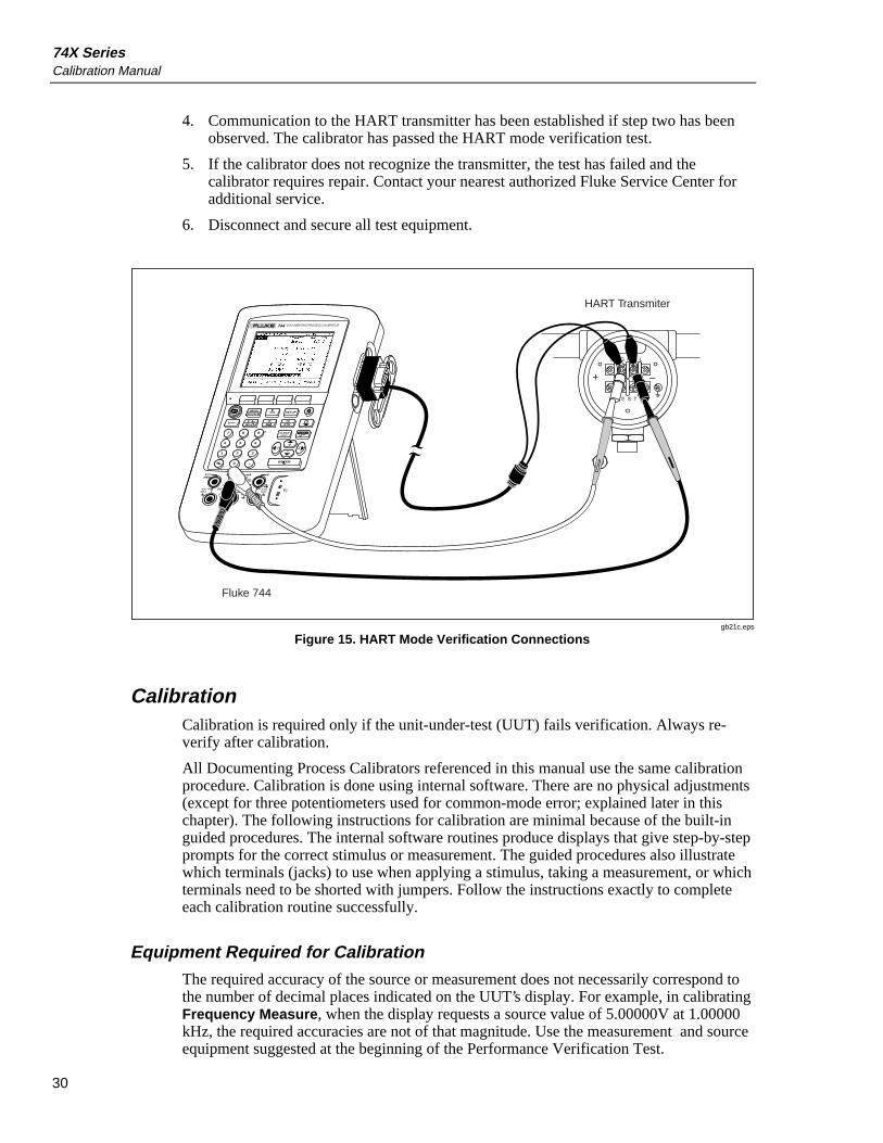
1. Connect the 744 to the HART transmitter as shown in Figure 15.
2. Press to activate HART mode. If required, press the appropriate blue soft keyto enable Loop Power.
3. The calibrator will recognize and identify the HART transmitter. When used with aModel 3051, the display will appear as follows:
gb20s.bmp
The Active Device screen provides the following information for all HARTtransmitters, supported or generic:
• Poll address (if not 0)• Model number and Tag ID• PV (Primary Variable)• PVAO (digital representation of the Analog Output)• PV LRV (PV Lower Range Value)• PV URV (PV Upper Range Value)• Softkeys for accessing HART operation menus
74X SeriesCalibration Manual
30
4. Communication to the HART transmitter has been established if step two has beenobserved. The calibrator has passed the HART mode verification test.
5. If the calibrator does not recognize the transmitter, the test has failed and thecalibrator requires repair. Contact your nearest authorized Fluke Service Center foradditional service.
6. Disconnect and secure all test equipment.
7 8 9
4 5 6
1 2 3
0 .
V
MEASSOURCE SETUPmA
VHz
TCRTD
CLEAR(ZERO)
ENTER
TC
mA mA VVRTD
RTD
SOURCE 300VMAX30V
MAX30V
MAX
30VMAX
MEASCAT
DOCUMENTING PROCESS CALIBRATOR744
S I G N A L
T E S T
+ –
Fluke 744
HART Transmiter
gb21c.eps
Figure 15. HART Mode Verification Connections
CalibrationCalibration is required only if the unit-under-test (UUT) fails verification. Always re-verify after calibration.
All Documenting Process Calibrators referenced in this manual use the same calibrationprocedure. Calibration is done using internal software. There are no physical adjustments(except for three potentiometers used for common-mode error; explained later in thischapter). The following instructions for calibration are minimal because of the built-inguided procedures. The internal software routines produce displays that give step-by-stepprompts for the correct stimulus or measurement. The guided procedures also illustratewhich terminals (jacks) to use when applying a stimulus, taking a measurement, or whichterminals need to be shorted with jumpers. Follow the instructions exactly to completeeach calibration routine successfully.
Equipment Required for Calibration
The required accuracy of the source or measurement does not necessarily correspond tothe number of decimal places indicated on the UUT’s display. For example, in calibratingFrequency Measure, when the display requests a source value of 5.00000V at 1.00000kHz, the required accuracies are not of that magnitude. Use the measurement and sourceequipment suggested at the beginning of the Performance Verification Test.

Calibration
31
Calibration Status Indicator
The calibration display is accessed by pressing [SETUP], and then the Next Page softkeythree times. At the top of the display is the Calibration Status followed by a number.This number is incremented after each subroutine is finished and the new constants aresaved. Doing a complete calibration increments the Calibration Status by 10. Becausethe Calibration Status number is changed only by a re-calibration, it can be used toconfirm that previous cal constants have not been changed.
Calibration Constant Out of Bounds
If one or more of the calibration stimuli (or measurements) were out of range during acalibration routine, or the cabling arrangement was incorrect, the message [Error -Calibration Constant Out of Bounds] will appear at the end of the routine. A generalfault with the UUT can also be indicated by this error. The fault will first have to berectified before repeating the entire sub-routine.
Order of Calibration
There are ten (10) sub-routines in the Calibration menu display. The sub-routines are asfollows:
• Volts DC Measure
• Volts AC Measure
• Frequency Measure
• mA Measure
• Volts DC Source
• Frequency Source
• Ohms Source
• mA Source
• Ohms Measure
• TC Measure
To completely re-calibrate these Process Calibrators, do each of the 10 sub-routines. Atthe end of each sub-routines you are prompted to either save the new constants, orabandon them and start over.
The best course is to do them in order from top to bottom. However, the first seven areindependent and can be done in any order. The last three subroutines (mA Source, OhmsMeasure, and TC Measure) are dependent on previous calibration constants, and must bedone in a specific order, as follows:

74X SeriesCalibration Manual
32
1. If mA Source is to be calibrated, mA Measure should be calibrated first. In otherwords, re-calibrating mA Measure could affect mA Source.
2. If Ohms Measure is to be calibrated, the following sub-routines should be donefirst in the order shown: Volts DC Measure, mA Measure, mA Source, andOhms Measure. This means that re-calibrating Volts DC Measure or mAMeasure can have an impact on Ohms Measure.
3. If TC Measure is to be calibrated, Volts DC Source must be calibrated first.Calibrating Volts DC Source could affect TC Measure.
NoteTC Measure also characterizes component RT2, which could affect theTC Source function (of which there is no calibration sub-routine), andaffects the contrast of the display LCD.
How to Calibrate
Follow these general instructions for all calibrations:
• Operate the UUT on battery power. Make sure the battery is fully charged. Do notuse the battery eliminator (BE9005).
• Allow each item of calibration equipment to satisfy its specified warm-up period.
• Allow the UUT a minimum of 5 minutes to warm up.
• For each calibration, make sure the calibration equipment has settled and that the"unsettled" annunciator on the UUT is not displayed.
Proceed as follows:
1. Turn on the UUT , press [SETUP] , and then the Next Page softkey three times.
2. The cursor bar should be at the Volts DC Measure subroutine. If you want to startwith another subroutine, use the Ù (up) and Ú (down) keys to move the cursor to thedesired subroutine. To start, press the Calibrate softkey.
3. For Volts DC Measure, do as the display illustrates: connect a shorting bar across theright side high and low jacks (not the TC connector), then connect all three lows(commons) together with two jumpers. Press the Continue softkey.

Calibration
33
Caution Do not force a dual banana plug between any two jacks in the
horizontal orientation (see Figure 16). Doing so will damage thejacks. Use the supplied jumper wires. You can use a dual bananaplug in the vertical orientation.
NOT OK
VRTD
MEASSOURCE
mA mA
RTD
V
300VMAX
30V MAXTC
VRTD
MEASSOURCE
mA mA
RTD
V
300VMAX
30V MAXTC
VRTD
MEASSOURCE
mA mA
RTD
V
300VMAX
30V MAXTC
OK
OK
gb16f.eps
Figure 16. Proper and Improper Jumper Use
4. Again, do as the display illustrates: remove the shorting bar, connect the test leadsfrom the right side jacks to the output of the dc source.
5. The display requests an input of 100.000 mV dc but shows an allowed range of 90.0≤ 100.000 mV ≤ 110.0. Apply the requested input, or apply an input in the allowedrange, and use the numeric keys to enter the value into the UUT, followed by[ENTER]. Press the Continue softkey.
6. Apply the next requested value as in step 5. Press the Continue softkey.
Warning Some of the voltages required for calibration are dangerous.
To avoid injury or death from electric shock, do not touch liveconductors during high voltage calibration. Put the sourcedevice into Standby after each calibration step.
7. Continue applying voltages as requested. Make sure you follow the hookupinstructions each time because the input jack configuration changes.
8. When you complete the last point in the subroutine, the display asks you if you wantto save the new constants. If you save the new constants, the calibration takes effectand the Calibration Status counter is incremented and the date is updated. If youdiscard the constants at this point, the calibration has no effect, the CalibrationStatus counter is not incremented, and the date does not change.

74X SeriesCalibration Manual
34
The other functions are also calibrated by following the step-by-step instructions on thedisplay.Frequency Source: When you calibrate the [Frequency Source] function, it requeststhat you measure the frequency and voltage output. This signal is an approximate 50%duty cycle, positive square wave, and the amplitude needs to be measured in pk volts, somultiply the DMM reading by 2. The DMM must be a true-RMS type.mA Measure: When you calibrate the [mA Measure] function, the display requests 0.0mA input. This does not equate to a short between mA high and low. Instead, set thesource device to source 0.0 mA, which is in effect the same as an open circuit.TC Measure: For [TC Measure] calibration, refer to the Thermocouple Measure part ofthe Verification Procedure for the correct techniques. [TC Measure] should be calibratedusing ITS-90 standards.Ohms Source: Always configure the DMM in a 4-wire configuration.
Adjustment of PotentiometersThere are three potentiometers on the Main PCA: R61, R77, and R82. These are factoryadjusted to tune out common mode error. Normally these should never need re-adjustment. If after a repair you need to repeat this adjustment, proceed as follows.
1. Carefully gain access to the Main PCA, and carefully power on the UUT.
2. Set the calibrator to the [DC Voltage Measure] function.
3. Short the front panel V MEAS high and low jacks together.
4. Apply 10V at 60 Hz between the V MEAS high jack and TP12 on the Main PCB.
5. Adjust R82 for a minimum output measured between TP24 and TP12. This valuemust be less than 3 mV rms.
6. Remove the jumper, then set the UUT to the [DC Current Measure] function.
7. Apply 10V at 60 Hz between mA/Ω/RTD MEAS low jack (common) and TP12.
8. Adjust R61 for a minimum output measured between TP17 and TP12. This valuemust be less than 12 mV rms.
9. Set the UUT to the [TC Measure] function, any type.
10. Short the TC jack "+" and "-" terminals.
11. Apply 10V at 60 Hz between the TC jacks and TP12.
12. Adjust R77 for a minimum output measured between TP40 and TP12. This valuemust be less than 3 mV rms.
13. Remove the jumper.
Replaceable Parts
35
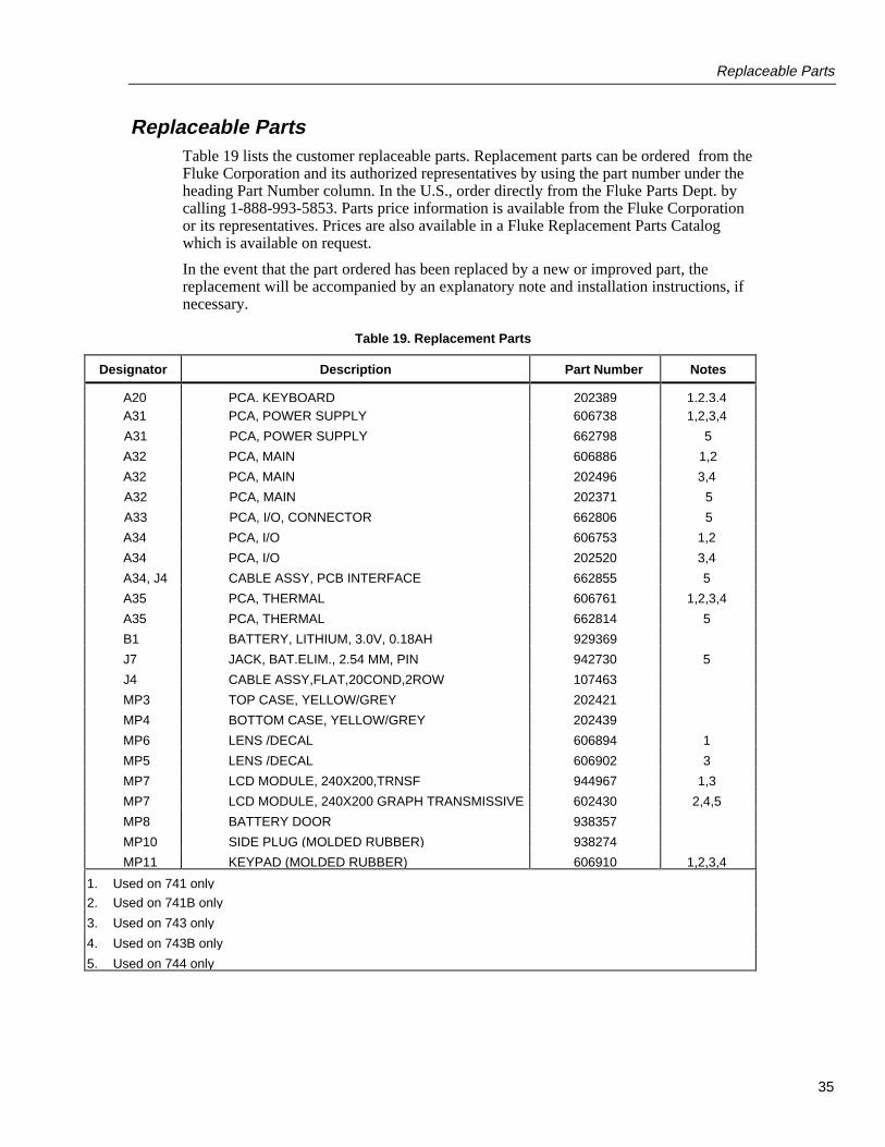
Replaceable PartsTable 19 lists the customer replaceable parts. Replacement parts can be ordered from theFluke Corporation and its authorized representatives by using the part number under theheading Part Number column. In the U.S., order directly from the Fluke Parts Dept. bycalling 1-888-993-5853. Parts price information is available from the Fluke Corporationor its representatives. Prices are also available in a Fluke Replacement Parts Catalogwhich is available on request.
In the event that the part ordered has been replaced by a new or improved part, thereplacement will be accompanied by an explanatory note and installation instructions, ifnecessary.
Table 19. Replacement Parts
Designator Description Part Number Notes
A20 PCA, KEYBOARD 202389 1,2,3,4 A31 PCA, POWER SUPPLY 606738 1,2,3,4
A31 PCA, POWER SUPPLY 662798 5
A32 PCA, MAIN 606886 1,2
A32 PCA, MAIN 202496 3,4
A32 PCA, MAIN 202371 5
A33 PCA, I/O, CONNECTOR 662806 5
A34 PCA, I/O 606753 1,2
A34 PCA, I/O 202520 3,4
A34, J4 CABLE ASSY, PCB INTERFACE 662855 5
A35 PCA, THERMAL 606761 1,2,3,4
A35 PCA, THERMAL 662814 5
B1 BATTERY, LITHIUM, 3.0V, 0.18AH 929369
J7 JACK, BAT.ELIM., 2.54 MM, PIN 942730 5
J4 CABLE ASSY,FLAT,20COND,2ROW 107463
MP3 TOP CASE, YELLOW/GREY 202421
MP4 BOTTOM CASE, YELLOW/GREY 202439
MP6 LENS /DECAL 606894 1
MP5 LENS /DECAL 606902 3
MP7 LCD MODULE, 240X200,TRNSF 944967 1,3
MP7 LCD MODULE, 240X200 GRAPH TRANSMISSIVE 602430 2,4,5
MP8 BATTERY DOOR 938357
MP10 SIDE PLUG (MOLDED RUBBER) 938274
MP11 KEYPAD (MOLDED RUBBER) 606910 1,2,3,4
1. Used on 741 only
2. Used on 741B only
3. Used on 743 only
4. Used on 743B only
5. Used on 744 only

74X SeriesCalibration Manual
36
Table 19. Replacement Parts (cont)
Designator Description Part Number Notes
MP14 BATTERY PACK ASSY 938170 1,2,3,4 MP14 BATTERY PACK, NIMH 665083 5
MP19 BATTERY PAD 949441
MP33 DECAL FOR TOP CASE 202413
MP77 DISPLAY BRACKET 946681
MP109 CABLE ASSY, 2 COND, 9P/9S D-SUB, 2 CLIPS 689653 5
MP111 GUIDE SET, ENG/FR/SP USER 689646 5
MP203 HANDLE STRAP 946769
MP210 CORD,LINE, EURO, 2.5M, 10A 769422
MP211 BATTERY CHARGER DECAL 949453 1,2,3,4
MP404 BAT CHRGR STAND 943746 1,2,3,4
MP405 PWR SUP, 30W, 15VDC @ 2A, INTL 690552 5
MP405 PWR SUP, BAT CHRGR, INTL, 15W, 15V@1A 944223 1,2,3,4
MP406 PWR SUP, BAT CHRGR, USA, 15W, 15V@1A 106200 1,2,3,4
MP406 PWR SUP 23W 15V @ 1.5A CHRGR/CNV USA 690344 5
MP821 MAIN SHIELD 606787
MP840 MANUAL SET, ENG/FR/SP, USER 688846 5
MP843 LENS DECAL 662871 5
MP843 LENS DECAL 949487 2
MP843 LENS DECAL 949490 4
MP94 KEYPAD 662863 5
P3 CONN., CIRCLULAR, 5 SOCKET 942714
P4 702 SERIAL CONN, D-SUB, 9 SCKT 942727
TM1 MANUAL, USER, ENG 601689 1,3
TM1 MANUAL, PERF BIND, USER, ENGLISH 644788 2,4
TM4 BC7210 INSTRUCTION SHEET,INTL 944020
1. Used on 741 only
2. Used on 741B only
3. Used on 743 only
4. Used on 743B only
5. Used on 744 only
Service CentersTo locate an authorized service center, call Fluke using any of the phone numbers listedbelow, or visit us on the World Wide Web: www.fluke.com
USA and Canada: 1-888-99-FLUKE (1-888-993-5853)Europe: +31-402-678-200Japan: +81-3-3434-0181Singapore: +65-738-5655Anywhere in the world: +1-425-356-5500