NORTH AMERICAN HEALTH CARE, INC. DOCUMENTATION–DOCUMENTATION– DOCUMENTATION DOCUMENTATION.
Documentation
KL6781
M-Bus Master Terminals
2.0.02018-01-16
Version:Date:


Table of contents
KL6781 3Version: 2.0.0
Table of contents1 Foreword .................................................................................................................................................... 5
1.1 Notes on the documentation........................................................................................................... 51.2 Safety instructions .......................................................................................................................... 61.3 Documentation Issue Status........................................................................................................... 7
2 Product overview....................................................................................................................................... 82.1 Introduction ..................................................................................................................................... 82.2 Technical data of the KL6781 ......................................................................................................... 92.3 LED displays................................................................................................................................. 10
3 Mounting and wiring ............................................................................................................................... 113.1 Installation on mounting rails ........................................................................................................ 113.2 Installation instructions for enhanced mechanical load capacity .................................................. 133.3 Connection.................................................................................................................................... 14
3.3.1 Connection system........................................................................................................... 143.3.2 Wiring............................................................................................................................... 163.3.3 Connection....................................................................................................................... 17
4 Access from the user program .............................................................................................................. 184.1 Register Overview ........................................................................................................................ 184.2 Control and status word................................................................................................................ 194.3 Process image .............................................................................................................................. 214.4 Mapping ........................................................................................................................................ 224.5 Register description ...................................................................................................................... 234.6 Examples of Register Communication.......................................................................................... 25
4.6.1 Example 1: reading the firmware version from Register 9 ............................................... 254.6.2 Example 2: Writing to an user register ............................................................................. 25
5 M-bus ........................................................................................................................................................ 285.1 Introduction ................................................................................................................................... 285.2 Overview....................................................................................................................................... 285.3 Topology ....................................................................................................................................... 29
6 Programming ........................................................................................................................................... 306.1 TwinCAT libraries ......................................................................................................................... 30
7 Appendix .................................................................................................................................................. 317.1 Support and Service ..................................................................................................................... 31

Table of contents
KL67814 Version: 2.0.0

Foreword
KL6781 5Version: 2.0.0
1 Foreword
1.1 Notes on the documentation
Intended audience
This description is only intended for the use of trained specialists in control and automation engineering whoare familiar with the applicable national standards.It is essential that the documentation and the following notes and explanations are followed when installingand commissioning these components.It is the duty of the technical personnel to use the documentation published at the respective time of eachinstallation and commissioning.
The responsible staff must ensure that the application or use of the products described satisfy all therequirements for safety, including all the relevant laws, regulations, guidelines and standards.
Disclaimer
The documentation has been prepared with care. The products described are, however, constantly underdevelopment.
We reserve the right to revise and change the documentation at any time and without prior announcement.
No claims for the modification of products that have already been supplied may be made on the basis of thedata, diagrams and descriptions in this documentation.
Trademarks
Beckhoff®, TwinCAT®, EtherCAT®, Safety over EtherCAT®, TwinSAFE®, XFC® and XTS® are registeredtrademarks of and licensed by Beckhoff Automation GmbH.Other designations used in this publication may be trademarks whose use by third parties for their ownpurposes could violate the rights of the owners.
Patent Pending
The EtherCAT Technology is covered, including but not limited to the following patent applications andpatents: EP1590927, EP1789857, DE102004044764, DE102007017835 with corresponding applications orregistrations in various other countries.
The TwinCAT Technology is covered, including but not limited to the following patent applications andpatents: EP0851348, US6167425 with corresponding applications or registrations in various other countries.
EtherCAT® is registered trademark and patented technology, licensed by Beckhoff Automation GmbH,Germany
Copyright
© Beckhoff Automation GmbH & Co. KG, Germany.The reproduction, distribution and utilization of this document as well as the communication of its contents toothers without express authorization are prohibited.Offenders will be held liable for the payment of damages. All rights reserved in the event of the grant of apatent, utility model or design.
Foreword
KL67816 Version: 2.0.0
1.2 Safety instructions
Safety regulations
Please note the following safety instructions and explanations!Product-specific safety instructions can be found on following pages or in the areas mounting, wiring,commissioning etc.
Exclusion of liability
All the components are supplied in particular hardware and software configurations appropriate for theapplication. Modifications to hardware or software configurations other than those described in thedocumentation are not permitted, and nullify the liability of Beckhoff Automation GmbH & Co. KG.
Personnel qualification
This description is only intended for trained specialists in control, automation and drive engineering who arefamiliar with the applicable national standards.
Description of symbols
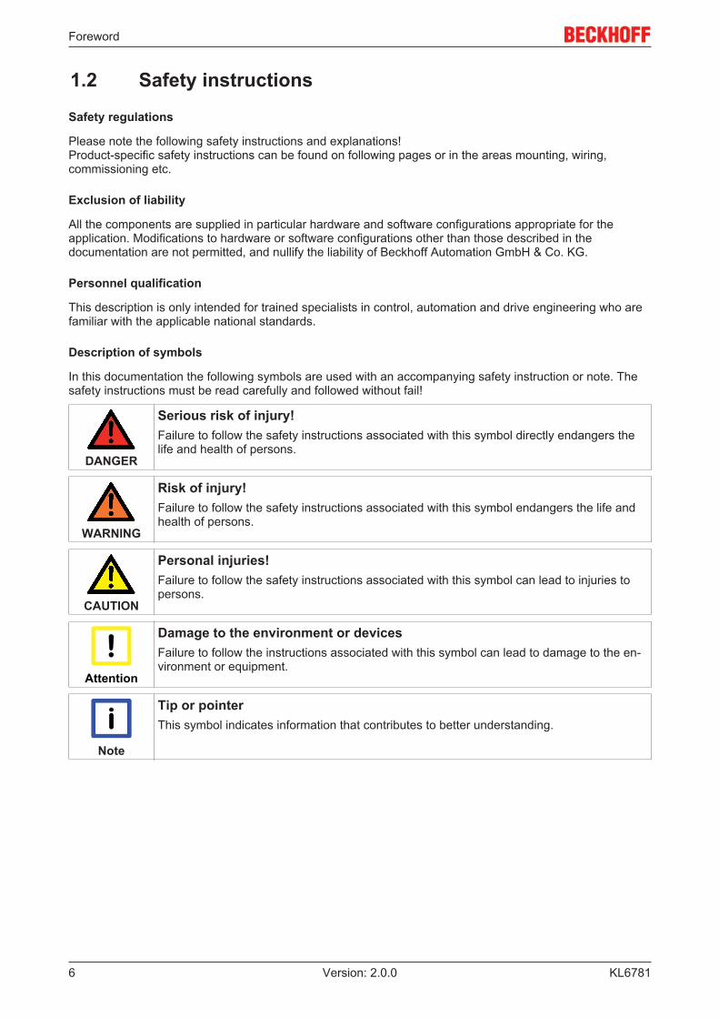
In this documentation the following symbols are used with an accompanying safety instruction or note. Thesafety instructions must be read carefully and followed without fail!
DANGER
Serious risk of injury!Failure to follow the safety instructions associated with this symbol directly endangers thelife and health of persons.
WARNING
Risk of injury!Failure to follow the safety instructions associated with this symbol endangers the life andhealth of persons.
CAUTION
Personal injuries!Failure to follow the safety instructions associated with this symbol can lead to injuries topersons.
Attention
Damage to the environment or devicesFailure to follow the instructions associated with this symbol can lead to damage to the en-vironment or equipment.
Note
Tip or pointerThis symbol indicates information that contributes to better understanding.

Foreword
KL6781 7Version: 2.0.0
1.3 Documentation Issue StatusVersion Comment2.0.0 • Migration1.4.0 • Programming description moved to the TwinCAT Information System [} 30].
• Library updated to version 2.0.1• Technical data updated
1.3.0 • Function block FB_MBUS_SBC_ALD1 added• Library updated to version 120
1.2.0 • Programming chapter updated1.1.0 • Foreword updated
• Mounting instructions extended• Description of control and status word expanded• Register description extended• M-bus chapter added• Programming chapter extended
1.0.0 • First release
Firmware and hardware versions
Documentation Version
KL6781Firmware Hardware
2.0.0 1C 031.4.0 1B 011.3.0 1B 011.2.0 1B 011.1.0 1B 011.0.0 1A 00
The firmware and hardware versions (delivery state) can be found in the serial number printed on the side ofthe terminal.
Syntax of the serial number
Structure of the serial number: KK YY FF HH
KK - week of production (CW, calendar week)YY - year of productionFF - firmware versionHH - hardware version
Example with ser. no.: 50 11 1A 00:
50 - week of production 5011- year of production 20111A - firmware version 1A00 - hardware version 00

Product overview
KL67818 Version: 2.0.0
2 Product overview
2.1 Introduction
Fig. 1: KL6781
The KL6781 M-bus master terminal enables direct connection of M-Bus devices. The M-bus (meter bus) is afieldbus for consumption data acquisition from electricity, water, gas or energy meters.
The KL6781 does not contain the M-bus protocol but converts the K-bus data to an M-bus compliant format.On the K-bus, 24 bytes are available for this purpose for each M-bus master terminal.
The TwinCAT M-bus library enables operation without external M-bus gateway, i.e. the M-bus devices canbe connected directly to the KL6781.
With a total line length of 300 m, up to 40 M-bus devices can be operated at a KL6781.

Product overview
KL6781 9Version: 2.0.0
2.2 Technical data of the KL6781Technical Data KL6781Data transfer channels 1M-bus devices max. 40Transmission standard M-bus propertiesData transfer rate 300...9600 baud (default 2,400 baud)Bus access Master-slave technique (polling)Cable length max. 300 mCurrent consumption from the K-bus typically 65 mACurrent consumption from power contacts max. 250 mAShort-circuit strength yesElectrical isolation 500 V (K-bus / M-bus)Width in the process image input/output: 24 bytesConfiguration TwinCAT PLC (M-bus function blocks)Rated voltage 24 VDC (-15% / +20%)Input voltage 24 VDC (-15% / +20%)Weight approx. 60 gMounting [} 11] on 35 mm mounting rail conforms to EN 60715Permissible ambient temperature range duringoperation
0 °C ... +55 °C
Permissible ambient temperature range during storage -25 °C ... +85 °CPermissible relative humidity 95 %, no condensationVibration / shock resistance conforms to EN 60068-2-6 / EN 60068-2-27
see also installation instructions [} 13] forterminals with enhanced mechanical load capacity
EMC immunity / emission conforms to EN 61000-6-2 / EN 61000-6-4Protection class IP20Installation position variableApproval CE, UL

Product overview
KL678110 Version: 2.0.0
2.3 LED displays
Fig. 2: LEDs
LED Color MeaningRun green This LED indicates the terminal's operating state:
on Normal operationoff The RUN LED goes out if no process data is transmitted to the terminal from the Bus
Coupler for 100 ms.Error red General error is signaledSend green Data transmission on the M-busReceive green Data transmission on the M-bus

Mounting and wiring
KL6781 11Version: 2.0.0
3 Mounting and wiring
3.1 Installation on mounting rails
WARNING
Risk of electric shock and damage of device!Bring the bus terminal system into a safe, powered down state before starting installation,disassembly or wiring of the Bus Terminals!
Assembly
Fig. 3: Attaching on mounting rail
The Bus Coupler and Bus Terminals are attached to commercially available 35 mm mounting rails (DIN railsaccording to EN 60715) by applying slight pressure:
1. First attach the Fieldbus Coupler to the mounting rail.2. The Bus Terminals are now attached on the right-hand side of the Fieldbus Coupler. Join the compo-
nents with tongue and groove and push the terminals against the mounting rail, until the lock clicksonto the mounting rail.If the Terminals are clipped onto the mounting rail first and then pushed together without tongue andgroove, the connection will not be operational! When correctly assembled, no significant gap shouldbe visible between the housings.
Note
Fixing of mounting railsThe locking mechanism of the terminals and couplers extends to the profile of the mountingrail. At the installation, the locking mechanism of the components must not come into con-flict with the fixing bolts of the mounting rail. To mount the mounting rails with a height of7.5 mm under the terminals and couplers, you should use flat mounting connections (e.g.countersunk screws or blind rivets).

Mounting and wiring
KL678112 Version: 2.0.0
Disassembly
Fig. 4: Disassembling of terminal
Each terminal is secured by a lock on the mounting rail, which must be released for disassembly:
1. Pull the terminal by its orange-colored lugs approximately 1 cm away from the mounting rail. In doingso for this terminal the mounting rail lock is released automatically and you can pull the terminal out ofthe bus terminal block easily without excessive force.
2. Grasp the released terminal with thumb and index finger simultaneous at the upper and lower groovedhousing surfaces and pull the terminal out of the bus terminal block.
Connections within a bus terminal block
The electric connections between the Bus Coupler and the Bus Terminals are automatically realized byjoining the components:
• The six spring contacts of the K-Bus/E-Bus deal with the transfer of the data and the supply of the BusTerminal electronics.
• The power contacts deal with the supply for the field electronics and thus represent a supply rail withinthe bus terminal block. The power contacts are supplied via terminals on the Bus Coupler (up to 24 V)or for higher voltages via power feed terminals.
Note
Power ContactsDuring the design of a bus terminal block, the pin assignment of the individual Bus Termi-nals must be taken account of, since some types (e.g. analog Bus Terminals or digital 4-channel Bus Terminals) do not or not fully loop through the power contacts. Power FeedTerminals (KL91xx, KL92xx or EL91xx, EL92xx) interrupt the power contacts and thus rep-resent the start of a new supply rail.
PE power contact
The power contact labeled PE can be used as a protective earth. For safety reasons this contact mates firstwhen plugging together, and can ground short-circuit currents of up to 125 A.

Mounting and wiring
KL6781 13Version: 2.0.0
Fig. 5: Power contact on left side
Attention
Possible damage of the deviceNote that, for reasons of electromagnetic compatibility, the PE contacts are capacitativelycoupled to the mounting rail. This may lead to incorrect results during insulation testing orto damage on the terminal (e.g. disruptive discharge to the PE line during insulation testingof a consumer with a nominal voltage of 230 V). For insulation testing, disconnect the PEsupply line at the Bus Coupler or the Power Feed Terminal! In order to decouple furtherfeed points for testing, these Power Feed Terminals can be released and pulled at least10 mm from the group of terminals.
WARNING
Risk of electric shock!The PE power contact must not be used for other potentials!
3.2 Installation instructions for enhanced mechanical loadcapacity
WARNING
Risk of injury through electric shock and damage to the device!Bring the Bus Terminal system into a safe, de-energized state before starting mounting,disassembly or wiring of the Bus Terminals!
Additional checks
The terminals have undergone the following additional tests:
Verification ExplanationVibration 10 frequency runs in 3 axes
6 Hz < f < 60 Hz displacement 0.35 mm, constant amplitude60.1 Hz < f < 500 Hz acceleration 5 g, constant amplitude
Shocks 1000 shocks in each direction, in 3 axes25 g, 6 ms
Mounting and wiring
KL678114 Version: 2.0.0
Additional installation instructions
For terminals with enhanced mechanical load capacity, the following additional installation instructions apply:
• The enhanced mechanical load capacity is valid for all permissible installation positions• Use a mounting rail according to EN 60715 TH35-15• Fix the terminal segment on both sides of the mounting rail with a mechanical fixture, e.g. an earth
terminal or reinforced end clamp• The maximum total extension of the terminal segment (without coupler) is:
64 terminals (12 mm mounting with) or 32 terminals (24 mm mounting with)• Avoid deformation, twisting, crushing and bending of the mounting rail during edging and installation of
the rail• The mounting points of the mounting rail must be set at 5 cm intervals• Use countersunk head screws to fasten the mounting rail• The free length between the strain relief and the wire connection should be kept as short as possible. A
distance of approx. 10 cm should be maintained to the cable duct.
3.3 Connection
3.3.1 Connection system
WARNING
Risk of electric shock and damage of device!Bring the bus terminal system into a safe, powered down state before starting installation,disassembly or wiring of the Bus Terminals!
Overview
The Bus Terminal system offers different connection options for optimum adaptation to the respectiveapplication:
• The terminals of ELxxxx and KLxxxx series with standard wiring include electronics and connectionlevel in a single enclosure.
• The terminals of ESxxxx and KSxxxx series feature a pluggable connection level and enable steadywiring while replacing.
• The High Density Terminals (HD Terminals) include electronics and connection level in a singleenclosure and have advanced packaging density.
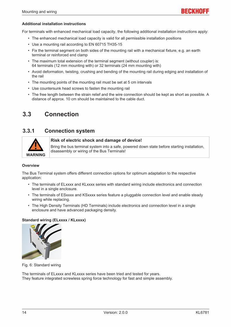
Standard wiring (ELxxxx / KLxxxx)
Fig. 6: Standard wiring
The terminals of ELxxxx and KLxxxx series have been tried and tested for years.They feature integrated screwless spring force technology for fast and simple assembly.

Mounting and wiring
KL6781 15Version: 2.0.0
Pluggable wiring (ESxxxx / KSxxxx)
Fig. 7: Pluggable wiring
The terminals of ESxxxx and KSxxxx series feature a pluggable connection level.The assembly and wiring procedure is the same as for the ELxxxx and KLxxxx series.The pluggable connection level enables the complete wiring to be removed as a plug connector from the topof the housing for servicing.The lower section can be removed from the terminal block by pulling the unlocking tab. Insert the new component and plug in the connector with the wiring. This reduces the installation time andeliminates the risk of wires being mixed up.
The familiar dimensions of the terminal only had to be changed slightly. The new connector adds about 3mm. The maximum height of the terminal remains unchanged.
A tab for strain relief of the cable simplifies assembly in many applications and prevents tangling of individualconnection wires when the connector is removed.
Conductor cross sections between 0.08 mm2 and 2.5 mm2 can continue to be used with the proven springforce technology.
The overview and nomenclature of the product names for ESxxxx and KSxxxx series has been retained asknown from ELxxxx and KLxxxx series.
High Density Terminals (HD Terminals)
Fig. 8: High Density Terminals
The Bus Terminals from these series with 16 terminal points are distinguished by a particularly compactdesign, as the packaging density is twice as large as that of the standard 12 mm Bus Terminals. Massiveconductors and conductors with a wire end sleeve can be inserted directly into the spring loaded terminalpoint without tools.
Note
Wiring HD TerminalsThe High Density (HD) Terminals of the ELx8xx and KLx8xx series doesn't support plug-gable wiring.
Ultrasonically "bonded" (ultrasonically welded) conductors
Note
Ultrasonically “bonded" conductorsIt is also possible to connect the Standard and High Density Terminals with ultrasonically"bonded" (ultrasonically welded) conductors. In this case, please note the tables concern-ing the wire-size width below!

Mounting and wiring
KL678116 Version: 2.0.0
3.3.2 Wiring
WARNING
Risk of electric shock and damage of device!Bring the bus terminal system into a safe, powered down state before starting installation,disassembly or wiring of the Bus Terminals!
Terminals for standard wiring ELxxxx/KLxxxx and for pluggable wiring ESxxxx/KSxxxx
Fig. 9: Connecting a cable on a terminal point
Up to eight terminal points enable the connection of solid or finely stranded cables to the Bus Terminal. Theterminal points are implemented in spring force technology. Connect the cables as follows:
1. Open a terminal point by pushing a screwdriver straight against the stop into the square openingabove the terminal point. Do not turn the screwdriver or move it alternately (don't toggle).
2. The wire can now be inserted into the round terminal opening without any force.3. The terminal point closes automatically when the pressure is released, holding the wire securely and
permanently.
See the following table for the suitable wire size width.
Terminal housing ELxxxx, KLxxxx ESxxxx, KSxxxxWire size width (single core wires) 0.08 ... 2.5 mm2 0.08 ... 2.5 mm2
Wire size width (fine-wire conductors) 0.08 ... 2.5 mm2 0,08 ... 2.5 mm2
Wire size width (conductors with a wire end sleeve) 0.14 ... 1.5 mm2 0.14 ... 1.5 mm2
Wire stripping length 8 ... 9 mm 9 ... 10 mm
High Density Terminals (HD Terminals [} 15]) with 16 terminal points
The conductors of the HD Terminals are connected without tools for single-wire conductors using the directplug-in technique, i.e. after stripping the wire is simply plugged into the terminal point. The cables arereleased, as usual, using the contact release with the aid of a screwdriver. See the following table for thesuitable wire size width.
Mounting and wiring
KL6781 17Version: 2.0.0
Terminal housing High Density HousingWire size width (single core wires) 0.08 ... 1.5 mm2
Wire size width (fine-wire conductors) 0.25 ... 1.5 mm2
Wire size width (conductors with a wire end sleeve) 0.14 ... 0.75 mm2
Wire size width (ultrasonically “bonded" conductors) only 1.5 mm2
Wire stripping length 8 ... 9 mm
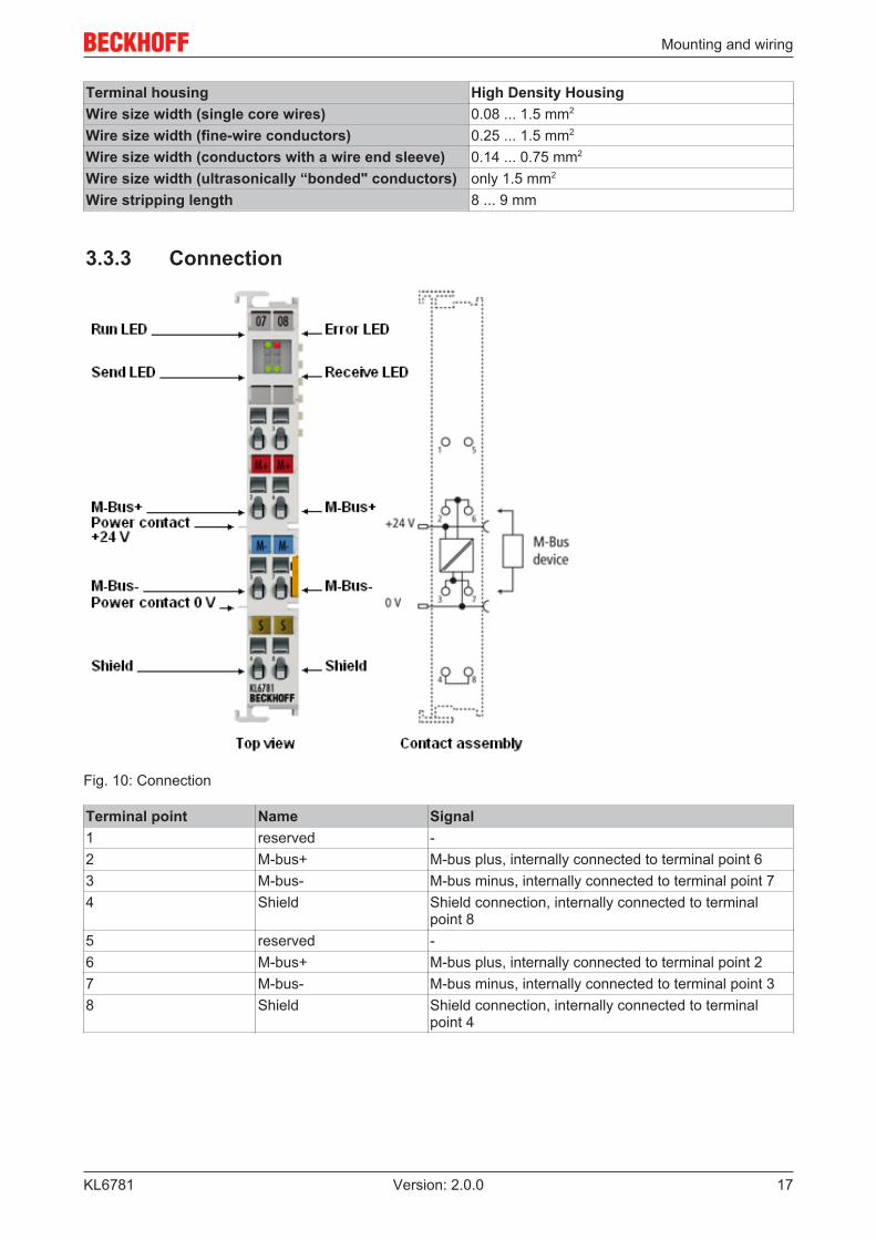
3.3.3 Connection
Fig. 10: Connection
Terminal point Name Signal1 reserved -2 M-bus+ M-bus plus, internally connected to terminal point 63 M-bus- M-bus minus, internally connected to terminal point 74 Shield Shield connection, internally connected to terminal
point 85 reserved -6 M-bus+ M-bus plus, internally connected to terminal point 27 M-bus- M-bus minus, internally connected to terminal point 38 Shield Shield connection, internally connected to terminal
point 4

Access from the user program
KL678118 Version: 2.0.0
4 Access from the user program
4.1 Register OverviewThe registers are used for parameterization the M-bus master terminal. They can be read or written bymeans of the register communication [} 25].
Register no. Comment Default value R/W MemoryR0 [} 23] Number of data bytes in the send buffer variable variable R RAM
R1 [} 23] Number of data bytes in the receive buffer variable variable R RAMR2 Number of parity errors 0x0000 0dec R -R3 Number of framing errors 0x0000 0dec R -R4 reserved 0x0000 0dec R -R5 reserved 0x0000 0dec R -R6 [} 23] Diagnostic register variable variable R RAM
R7 [} 23] Command register 0x0000 0dec R/W RAM
R8 [} 23] Terminal type 0x1A7D 6781dec R ROM
R9 [} 24] Firmware version variable variable R ROMR10 reserved 0x0000 0dec - -... ... ... ... ... ...R15 reserved 0x0000 0dec - -R16 Hardware version e.g. 0x0000 e.g.: 0dec ... EEPROMR17 reserved 0x0000 0dec - -... ... ... ... ... ...R18 reserved 0x0000 0dec - -R29 [} 24] Terminal type - special identification 0x0000 0dec R EEPROMR30 reserved 0x0000 0dec R/W RAMR31 [} 24] Code word register 0x0000 0dec R/W RAM
R32 [} 24] Baud rate register 0x0004 4dec R/W EEPROMR33 reserved 0x0000 0dec R/W -... ... ... ... ... ...R63 reserved 0x0000 0dec R/W -

Access from the user program
KL6781 19Version: 2.0.0
4.2 Control and status word
Process data mode
Control word (in process data mode)
The control word (CW) is located in the output process image [} 21], and is transmitted from the controllerto the terminal.
Bit CW.15 CW.14 CW.13 CW.12 CW.11 CW.10 CW.9 CW.8 CW.7 CW.6 CW.5 CW.4 CW.3 CW.2 CW.1 CW.0Name OL7 OL6 OL5 OL4 OL3 OL2 OL1 OL0 Reg - - - - IR RA TR
Key
Bit Name DescriptionCW.15 ... CW.8
OL7 ... OL0(OutLenght)
1dec...22dec
Number of output bytes () available for transfer from thecontroller to the terminal.
CW.7 Reg (RegAccess) 0bin Register communication off (process data mode)CW.6 ... CW.3 - 0bin reservedCW.2 IR
(InitRequest)0bin The controller once again requests the terminal to prepare for
serial data exchange.1bin The controller requests terminal for initialization. The
transmission and reception functions are disabled, the FIFOpointers are reset and the interface is initialized with thevalues in the appropriate registers. The terminalacknowledges completion of the initialization via bit SW.2[} 19] (IA).
CW.1 RA(ReceiveAccepted)
toggle The controller acknowledges receipt of data by changing thestate of this bit. Only then new data can be transferred fromthe terminal to the controller.
CW.0 TR(TransmitRequest)
toggle Via a change of state of this bit the controller notifies theterminal that the DataOut bytes contain the number of bytesindicated via the OL bits. The terminal acknowledges receiptof the data in the status byte via a change of state of bit SW.0[} 19] (TA). Only now new data can be transferred from thecontroller to the terminal.
Status word (in process data mode)
The status word (SW) is located in the input process image [} 21], and is transmitted from terminal to thecontroller.
Bit SW.15 SW.14 SW.13 SW.12 SW.11 SW.10 SW.9 SW.8 SW.7 SW.6 SW.5 SW.4 SW.3 SW.2 SW.1 SW.0Name IL7 IL6 IL5 IL4 IL3 IL2 IL1 IL0 Reg - - - BUF_F IA RR TA

Access from the user program
KL678120 Version: 2.0.0
Key
Bit Name DescriptionSW.15 ... SW8 IL7 ... IL0
(InLength)1dec ...22dec
Number of input bytes available for transfer from the terminalto the controller.
SW.7 Reg (RegAccess) 0bin Acknowledgment for process data modeSW.6 ... SW.4 - 0 reservedSW.3 BUF_F 1bin The reception FIFO is full. All further incoming data will be
lost!SW.2 IA
(InitAccepted bit)1bin Initialization was completed by the terminal.0bin The terminal is ready again for serial data exchange.
SW.1 RR(ReceiveRequest)
toggle Via a change of state of this bit the terminal notifies thecontroller that the DataIn bytes contain the number of bytesindicated via the IL bits. The controller has to acknowledgereceipt of the data in the control byte via a change of state ofbit CW.1 [} 19] (RA). Only then new data can be transferredfrom the terminal to the controller.
SW.0 TA(TransmitAccepted)
toggle The terminal acknowledges receipt of data by changing thestate of this bit. Only then new data can be transferred fromthe terminal to the controller
Register communication
Control word (in register communication)
The control word (CW) is located in the output process image [} 21], and is transmitted from the controllerto the terminal.
Bit CW.15 CW.14 CW.13 CW.12 CW.11 CW.10 CW.9 CW.8 CW.7 CW.6 CW.5 CW.4 CW.3 CW.2 CW.1 CW.0Name RegData: Reg R/W Reg. no.
Key
Bit Name DescriptionCW.15 ... CW.8
RegData: One byte of data to be written to the register. The other byte istransferred in the adjacent process data byte.
CW.7 Reg 1bin Register communication switched onCW.6 R/W 0bin Read access
1bin Write accessCW.5 to CW.0 Reg. no. Register number:
Enter the number of the register [} 18] that you want to- read with the input data word DataIN [} 21] and the HighByte of thestatus bytes (RegData) or- write the output data word DataOUT [} 21] and the HighByte ofcontrol word (RegData).
Status byte (for register communication)
The status word (SW) is located in the input process image [} 21], and is transmitted from terminal to thecontroller.
Bit SW.15 SW.14 SW.13 SW.12 SW.11 SW.10 SW.9 SW.8 SW.7 SW.6 SW.5 SW.4 SW.3 SW.2 SW.1 SW.0Name RegData: Reg R/W Reg. no.
Access from the user program
KL6781 21Version: 2.0.0
Key
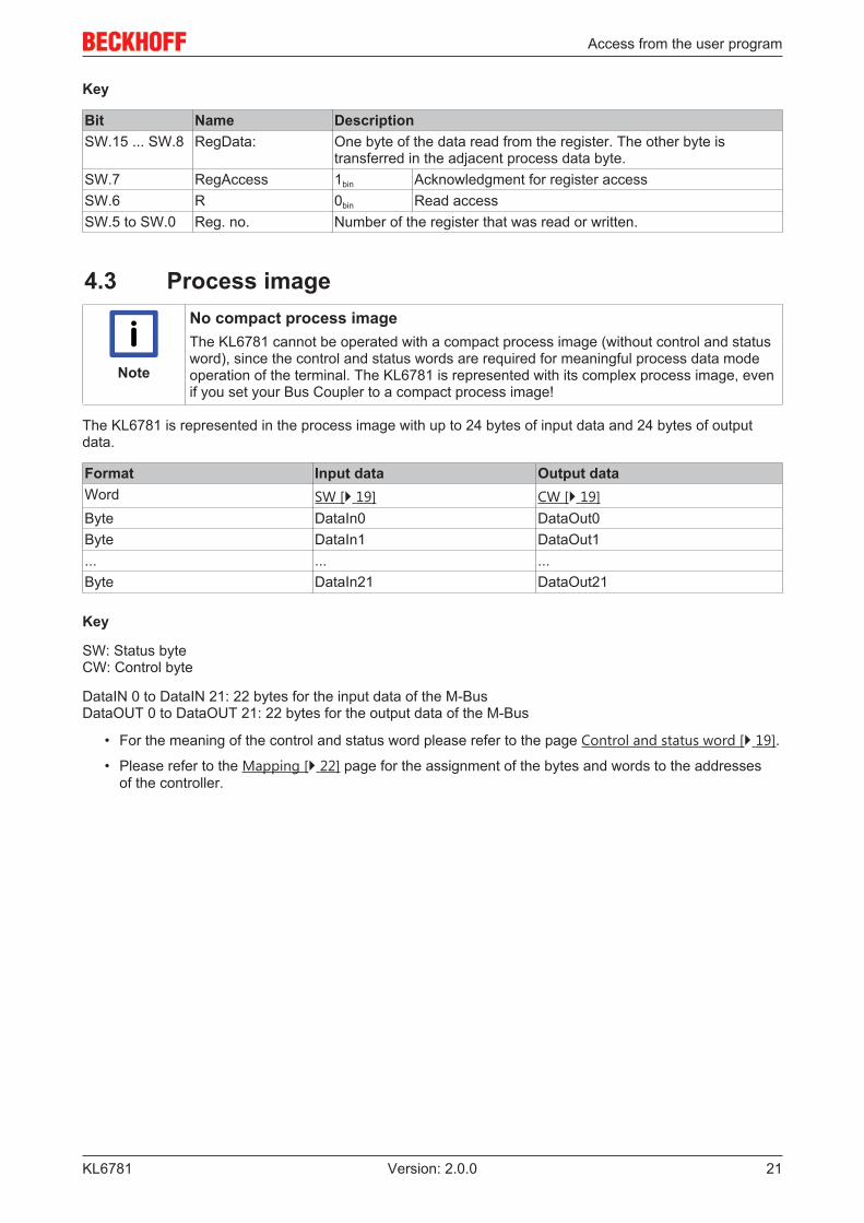
Bit Name DescriptionSW.15 ... SW.8 RegData: One byte of the data read from the register. The other byte is
transferred in the adjacent process data byte.SW.7 RegAccess 1bin Acknowledgment for register accessSW.6 R 0bin Read accessSW.5 to SW.0 Reg. no. Number of the register that was read or written.
4.3 Process image
Note
No compact process imageThe KL6781 cannot be operated with a compact process image (without control and statusword), since the control and status words are required for meaningful process data modeoperation of the terminal. The KL6781 is represented with its complex process image, evenif you set your Bus Coupler to a compact process image!
The KL6781 is represented in the process image with up to 24 bytes of input data and 24 bytes of outputdata.
Format Input data Output dataWord SW [} 19] CW [} 19]Byte DataIn0 DataOut0Byte DataIn1 DataOut1... ... ...Byte DataIn21 DataOut21
Key
SW: Status byteCW: Control byte
DataIN 0 to DataIN 21: 22 bytes for the input data of the M-BusDataOUT 0 to DataOUT 21: 22 bytes for the output data of the M-Bus
• For the meaning of the control and status word please refer to the page Control and status word [} 19].
• Please refer to the Mapping [} 22] page for the assignment of the bytes and words to the addressesof the controller.

Access from the user program
KL678122 Version: 2.0.0
4.4 MappingThe Bus Terminals occupy addresses within the process image of the controller. The assignment of processdata (input and output data) and parameterization data (control and status bytes) to the control addresses iscalled mapping. The type of mapping depends on:
• the fieldbus system used• the terminal type• the parameterization of the Bus Coupler (conditions) such as
◦ compact or complex evaluation◦ Intel or Motorola format◦ word alignment switched on or off
The following tables show the mapping depending on different conditions. For the content of the individualbytes please refer to pages Process image [} 21] and Control and status word [} 19].
Compact evaluation
Note
No compact process imageThe KL6781 cannot be operated with a compact process image (without control and statusword), since the control and status words are required for meaningful process data modeoperation of the terminal. The KL6781 is represented with its complex process image, evenif you set your Bus Coupler to a compact process image!
Complete evaluation
Complete evaluation in Intel format
Address Input data Output dataConditions Word offset High byte Low byte High byte Low byteComplete evaluation: anyMotorola format: noWord alignment: any
0 SW CW1 DataIN 1 DataIN 0 DataOUT 1 DataOUT 02 DataIN 3 DataIN 2 DataOUT 3 DataOUT 23 DataIN 5 DataIN 4 DataOUT 5 DataOUT 44 DataIN 7 DataIN 6 DataOUT 7 DataOUT 65 DataIN 9 DataIN 8 DataOUT 9 DataOUT 86 DataIN 11 DataIN 10 DataOUT 11 DataOUT 107 DataIN 13 DataIN 12 DataOUT 13 DataOUT 128 DataIN 15 DataIN 14 DataOUT 15 DataOUT 149 DataIN 17 DataIN 16 DataOUT 17 DataOUT 1610 DataIN 19 DataIN 18 DataOUT 19 DataOUT 1811 DataIN 21 DataIN 20 DataOUT 21 DataOUT 20
Access from the user program
KL6781 23Version: 2.0.0
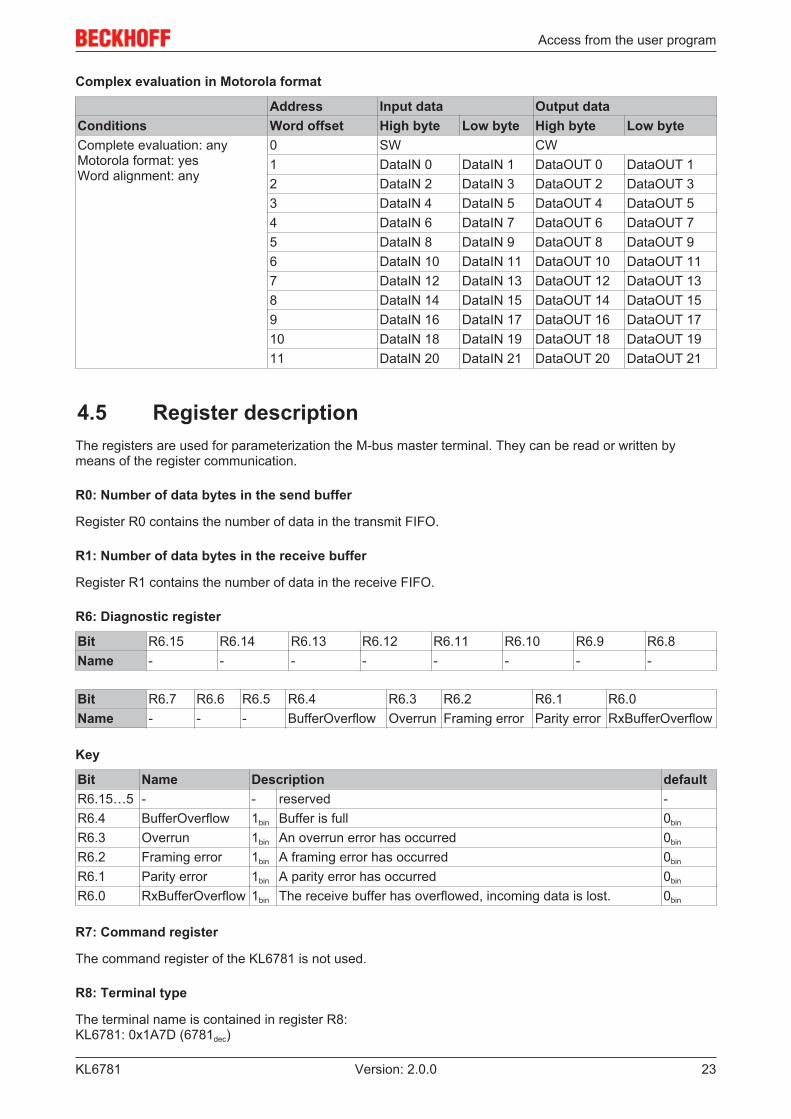
Complex evaluation in Motorola format
Address Input data Output dataConditions Word offset High byte Low byte High byte Low byteComplete evaluation: anyMotorola format: yesWord alignment: any
0 SW CW1 DataIN 0 DataIN 1 DataOUT 0 DataOUT 12 DataIN 2 DataIN 3 DataOUT 2 DataOUT 33 DataIN 4 DataIN 5 DataOUT 4 DataOUT 54 DataIN 6 DataIN 7 DataOUT 6 DataOUT 75 DataIN 8 DataIN 9 DataOUT 8 DataOUT 96 DataIN 10 DataIN 11 DataOUT 10 DataOUT 117 DataIN 12 DataIN 13 DataOUT 12 DataOUT 138 DataIN 14 DataIN 15 DataOUT 14 DataOUT 159 DataIN 16 DataIN 17 DataOUT 16 DataOUT 1710 DataIN 18 DataIN 19 DataOUT 18 DataOUT 1911 DataIN 20 DataIN 21 DataOUT 20 DataOUT 21
4.5 Register descriptionThe registers are used for parameterization the M-bus master terminal. They can be read or written bymeans of the register communication.
R0: Number of data bytes in the send buffer
Register R0 contains the number of data in the transmit FIFO.
R1: Number of data bytes in the receive buffer
Register R1 contains the number of data in the receive FIFO.
R6: Diagnostic register
Bit R6.15 R6.14 R6.13 R6.12 R6.11 R6.10 R6.9 R6.8Name - - - - - - - -
Bit R6.7 R6.6 R6.5 R6.4 R6.3 R6.2 R6.1 R6.0Name - - - BufferOverflow Overrun Framing error Parity error RxBufferOverflow
Key
Bit Name Description defaultR6.15…5 - - reserved -R6.4 BufferOverflow 1bin Buffer is full 0bin
R6.3 Overrun 1bin An overrun error has occurred 0bin
R6.2 Framing error 1bin A framing error has occurred 0bin
R6.1 Parity error 1bin A parity error has occurred 0bin
R6.0 RxBufferOverflow 1bin The receive buffer has overflowed, incoming data is lost. 0bin
R7: Command register
The command register of the KL6781 is not used.
R8: Terminal type
The terminal name is contained in register R8:KL6781: 0x1A7D (6781dec)

Access from the user program
KL678124 Version: 2.0.0
R9: Firmware version
Register R9 contains the ASCII coding of the terminal's firmware version, e.g. 0x3141 = '1A'. The '0x31'corresponds here to the ASCII character '1', while the '0x41' represents the ASCII character 'A'.This value cannot be changed.
R16: Hardware version
Register R16 contains the hardware version of the terminal.
R29: Terminal type - special identification
The name of the special type of the terminal is contained in register R29. KL6781-0000: 0x0000 (0000dec)
R31: Code word register• If you write values into the user registers without first entering the user code word (0x1235) into the
code word register, the terminal will not accept the supplied data.• If you write values into the user registers and have previously entered the user code word (0x1235) in
the code word register, these values are stored in the RAM registers and in the SEEPROM registersand are therefore retained when the terminal is restarted.
The code word is reset when the terminal is restarted.
R32: Baud rate register
Bit R32.15 R32.14 R32.13 R32.12 R32.11 R32.10 R32.9 R32.8Name - - - - - - - -
Bit R32.7 R32.6 R32.5 R32.4 R32.3 R32.2 R32.1 R32.0Name - - - - - Baud rate
Key
Bit Name Description defaultR32.15 - R32.3 - reserved 0bin
R32.2 - R32.0 Baud rate 110bin 9600 baud 100bin
101bin 4800 baud100bin 2400 baud (default)11bin 1200 baud010bin 600 baud001bin 300 baud

Access from the user program
KL6781 25Version: 2.0.0
4.6 Examples of Register CommunicationThe numbering of the bytes in the examples corresponds to the display without word alignment.
4.6.1 Example 1: reading the firmware version from Register 9
Output Data
Byte 0: Control byte Byte 1: DataOUT1, high byte Byte 2: DataOUT1, low byte0x89 (1000 1001bin) 0xXX 0xXX
Explanation:
• Bit 0.7 set means: Register communication switched on.• Bit 0.6 not set means: reading the register.• Bits 0.5 to 0.0 specify the register number 9 with 00 1001bin.• The output data word (byte 1 and byte 2) has no meaning during read access. To change a register,
write the required value into the output word.
Input Data (answer of the bus terminal)
Byte 0: Status byte Byte 1: DataIN1, high byte Byte 2: DataIN1, low byte0x89 0x33 0x41
Explanation:
• The terminal returns the value of the control byte as a receipt in the status byte.• The terminal returns the firmware version 0x3341 in the input data word (byte 1 and byte 2). This is to
be interpreted as an ASCII code:◦ ASCII code 0x33 represents the digit 3◦ ASCII code 0x41 represents the letter A
The firmware version is thus 3A.
4.6.2 Example 2: Writing to an user register
Note
Code wordIn normal mode all user registers are read-only with the exception of Register 31. In orderto deactivate this write protection you must write the code word (0x1235) into Register 31. Ifa value other than 0x1235 is written into Register 31, write protection is reactivated. Pleasenote that changes to a register only become effective after restarting the terminal (power-off/power-on).
I. Write the code word (0x1235) into Register 31.
Output Data
Byte 0: Control byte Byte 1: DataOUT1, high byte Byte 2: DataOUT1, low byte0xDF (1101 1111bin) 0x12 0x35
Explanation:
• Bit 0.7 set means: Register communication switched on.• Bit 0.6 set means: writing to the register.• Bits 0.5 to 0.0 specify the register number 31 with 01 1111bin.• The output data word (byte 1 and byte 2) contains the code word (0x1235) for deactivating write
protection.

Access from the user program
KL678126 Version: 2.0.0
Input Data (answer of the bus terminal)
Byte 0: Status byte Byte 1: DataIN1, high byte Byte 2: DataIN1, low byte0x9F (1001 1111bin) 0xXX 0xXX
Explanation:
• The terminal returns a value as a receipt in the status byte that differs only in bit 0.6 from the value ofthe control byte.
• The input data word (byte 1 and byte 2) is of no importance after the write access. Any values stilldisplayed are invalid!
II. Read Register 31 (check the set code word)
Output Data
Byte 0: Control byte Byte 1: DataOUT1, high byte Byte 2: DataOUT1, low byte0x9F (1001 1111bin) 0xXX 0xXX
Explanation:
• Bit 0.7 set means: Register communication switched on.• Bit 0.6 not set means: reading the register.• Bits 0.5 to 0.0 specify the register number 31 with 01 1111bin.• The output data word (byte 1 and byte 2) has no meaning during read access.
Input Data (answer of the bus terminal)
Byte 0: Status byte Byte 1: DataIN1, high byte Byte 2: DataIN1, low byte0x9F (1001 1111bin) 0x12 0x35
Explanation:
• The terminal returns the value of the control byte as a receipt in the status byte.• The terminal returns the current value of the code word register in the input data word (byte 1 and byte
2).
III. Write to Register 32 (change contents of the feature register)
Output data
Byte 0: Control byte Byte 1: DataIN1, high byte Byte 2: DataIN1, low byte0xE0 (1110 0000bin) 0x00 0x02
Explanation:
• Bit 0.7 set means: Register communication switched on.• Bit 0.6 set means: writing to the register.• Bits 0.5 to 0.0 indicate register number 32 with 10 0000bin.• The output data word (byte 1 and byte 2) contains the new value for the feature register.
CAUTION
Observe the register description!The value of 0x0002 given here is just an example! The bits of the feature register change the properties of the terminal and have a differentmeaning, depending on the type of terminal. Refer to the description of the feature registerof your terminal (chapter Register description) regarding the meaning of the individual bitsbefore changing the values.

Access from the user program
KL6781 27Version: 2.0.0
Input data (response from the Bus Terminal)
Byte 0: Status byte Byte 1: DataIN1, high byte Byte 2: DataIN1, low byte0xA0 (1010 0000bin) 0xXX 0xXX
Explanation:
• The terminal returns a value as a receipt in the status byte that differs only in bit 0.6 from the value ofthe control byte.
• The input data word (byte 1 and byte 2) is of no importance after the write access. Any values stilldisplayed are invalid!
IV. Read Register 32 (check changed feature register)
Output Data
Byte 0: Control byte Byte 1: DataOUT1, high byte Byte 2: DataOUT1, low byte0xA0 (1010 0000bin) 0xXX 0xXX
Explanation:
• Bit 0.7 set means: Register communication switched on.• Bit 0.6 not set means: reading the register.• Bits 0.5 to 0.0 indicate register number 32 with 10 0000bin.• The output data word (byte 1 and byte 2) has no meaning during read access.
Input Data (answer of the bus terminal)
Byte 0: Status byte Byte 1: DataIN1, high byte Byte 2: DataIN1, low byte0xA0 (1010 0000bin) 0x00 0x02
Explanation:
• The terminal returns the value of the control byte as a receipt in the status byte.• The terminal returns the current value of the feature register in the input data word (byte 1 and byte 2).
V. Write Register 31 (reset code word)
Output Data
Byte 0: Control byte Byte 1: DataOUT1, high byte Byte 2: DataOUT1, low byte0xDF (1101 1111bin) 0x00 0x00
Explanation:
• Bit 0.7 set means: Register communication switched on.• Bit 0.6 set means: writing to the register.• Bits 0.5 to 0.0 specify the register number 31 with 01 1111bin.• The output data word (byte 1 and byte 2) contains 0x0000 for reactivating write protection.
Input Data (answer of the bus terminal)
Byte 0: Status byte Byte 1: DataIN1, high byte Byte 2: DataIN1, low byte0x9F (1001 1111bin) 0xXX 0xXX
Explanation:
• The terminal returns a value as a receipt in the status byte that differs only in bit 0.6 from the value ofthe control byte.
• The input data word (byte 1 and byte 2) is of no importance after the write access. Any values stilldisplayed are invalid!

M-bus
KL678128 Version: 2.0.0
5 M-bus
5.1 IntroductionM-Bus = metering bus
The M-Bus is a fieldbus for the acquisition of consumption data (e.g. energy meters). Further details aboutM-Bus can be found under www.m-bus.com. The M-Bus is European standard and is described in theEN1434 standard. The data are sent serially from a slave (measuring device) to a master (level converterwith PC). Master and slave are connected via a two-wire line that is protected against polarity reversal. Withprimary addressing up to 250 slaves can be connected in star, strand or tree topologies. Ring structures arenot permitted. Devices from different manufacturers can be operated on the same bus.
The master controls the communication on the bus by requesting data from the slaves. The slaves canrespond with a fixed or variable data structure. The M-Bus library only evaluates data with variable datastructure (low byte first). The slaves do not communicate with each other. The data have to be requestedsequentially from the slaves.
5.2 Overview
Fig. 11: KL6781 as M-bus master

M-bus
KL6781 29Version: 2.0.0
5.3 Topology
Star, line and tree topology
Fig. 12: Star, line and tree topology
Ring topology
Fig. 13: Ring topology
Note
Ring topology is not supportedAlthough ring topology is possible with the M-bus, it is not recommended and therefore notsupported by Beckhoff.

Programming
KL678130 Version: 2.0.0
6 Programming
6.1 TwinCAT librariesSoftware documentation in the Beckhoff Information System:
TwinCAT 2: TwinCAT 2 PLC Lib: M-bus
TwinCAT 3: TwinCAT 3 PLC Lib: Tc2_MBus

Appendix
KL6781 31Version: 2.0.0
7 Appendix
7.1 Support and ServiceBeckhoff and their partners around the world offer comprehensive support and service, making available fastand competent assistance with all questions related to Beckhoff products and system solutions.
Beckhoff's branch offices and representatives
Please contact your Beckhoff branch office or representative for local support and service on Beckhoffproducts!
The addresses of Beckhoff's branch offices and representatives round the world can be found on her internetpages:http://www.beckhoff.com
You will also find further documentation for Beckhoff components there.
Beckhoff Headquarters
Beckhoff Automation GmbH & Co. KG
Huelshorstweg 2033415 VerlGermany
Phone: +49(0)5246/963-0Fax: +49(0)5246/963-198e-mail: [email protected]
Beckhoff Support
Support offers you comprehensive technical assistance, helping you not only with the application ofindividual Beckhoff products, but also with other, wide-ranging services:
• support• design, programming and commissioning of complex automation systems• and extensive training program for Beckhoff system components
Hotline: +49(0)5246/963-157Fax: +49(0)5246/963-9157e-mail: [email protected]
Beckhoff Service
The Beckhoff Service Center supports you in all matters of after-sales service:
• on-site service• repair service• spare parts service• hotline service
Hotline: +49(0)5246/963-460Fax: +49(0)5246/963-479e-mail: [email protected]

List of illustrations
KL678132 Version: 2.0.0
List of illustrationsFig. 1 KL6781 ........................................................................................................................................ 8Fig. 2 LEDs ............................................................................................................................................ 10Fig. 3 Attaching on mounting rail ........................................................................................................... 11Fig. 4 Disassembling of terminal............................................................................................................ 12Fig. 5 Power contact on left side............................................................................................................ 13Fig. 6 Standard wiring............................................................................................................................ 14Fig. 7 Pluggable wiring .......................................................................................................................... 15Fig. 8 High Density Terminals................................................................................................................ 15Fig. 9 Connecting a cable on a terminal point ....................................................................................... 16Fig. 10 Connection................................................................................................................................... 17Fig. 11 KL6781 as M-bus master............................................................................................................. 28Fig. 12 Star, line and tree topology.......................................................................................................... 29Fig. 13 Ring topology............................................................................................................................... 29