Document Title for the Traffic Flow Management...
58
Final, Release 9 CACR, Phase 2 Contract Number: DTFAWA-04-C-00045 CDRL: E05 February 11, 2013 Prepared for: U.S. Federal Aviation Administration Prepared by: CSC North American Public Sector – Civil Group 15245 Shady Grove Road Rockville, MD 30850 Document Title for the Traffic Flow Management-Modernization (TFM-M) Program Traffic Flow Management System-to- National Airspace Data Interchange Network Internet Protocol (TFMS-to-NADIN IP) Interface Control Document (ICD) for the Traffic Flow Management-Modernization (TFM-M) Program
Transcript of Document Title for the Traffic Flow Management...
Final, Release 9
CACR, Phase 2
Contract Number: DTFAWA-04-C-00045 CDRL: E05
February 11, 2013
Prepared for: U.S. Federal Aviation Administration
Prepared by:
CSC North American Public Sector – Civil Group
15245 Shady Grove Road Rockville, MD 30850
Document Title for the Traffic Flow Management-Modernization (TFM-M) Program
Traffic Flow Management System-to-National Airspace Data Interchange Network Internet Protocol (TFMS-to-NADIN IP) Interface Control Document (ICD) for the Traffic Flow Management-Modernization (TFM-M) Program

TFMS-to-NADIN IP Interface Control Document CSC/TFMM-13/1620 February 2013 Release 7
ii
Traffic Flow Management System-to-National Airspace Data Interchange Network Internet Protocol (TFMS-to-
NADIN IP) Interface Control Document (ICD) for the Traffic Flow Management-Modernization (TFM-M)
Program
Final, Release 9
CACR, Phase 2
Contract Number: DTFAWA-04-C-00045 CDRL: E05
February 11, 2013
Prepared for: U.S. Federal Aviation Administration
Prepared by:
CSC North American Public Sector – Civil Group
15245 Shady Grove Road Rockville, MD 20850

TFMS-to-NADIN IP Interface Control Document CSC/TFMM-13/1620 February 2013 Release 7
iii
CSC/TFMM-10/1077
Release 9, Draft
February 11, 2013
INTERFACE CONTROL DOCUMENT
APPROVAL SIGNATURE PAGE
TFMS/NADIN IP
APPROVAL SIGNATURES
PARTICIPANT NAME DATE

TFMS-to-NADIN IP Interface Control Document CSC/TFMM-13/1620 February 2013 Release 7
iv
Document History Record
Release Date Comment
Draft, Release 5 May 24, 2010 Contractual delivery. Addresses Release 5
Interface Design.
This version reflects significant restructuring of
the Release 3 Final Revision to improve the
flow of information and also to enhance easy
maintenance.
Added Appendix B in which Advisories and
General Mesages file is embedded as a
document link.
Final, Release 5 March 1, 2011 Contractual delivery. Addresses the following
CR:
TFMMP00032566
TFMMP00032688
Final, Release 9 February 11,2013 Contractual delivery.
The Advisories and General Messages (see
Appendix B) are revised to include 3 new
advisories to support Collobaorative Trajectory
Options Program (CTOP) Traffic Management
Initiative (TMI)

TFMS-to-NADIN IP Interface Control Document CSC/TFMM-13/1620 February 2013 Release 7
v
Table of Contents 1 Scope...................................................................................................... 1-1 1.1 Scope and Purpose ................................................................................ 1-1 1.2 Subsystem Responsibility List ................................................................ 1-1
1.3 Document Organization .......................................................................... 1-1 2 Applicable Documents ............................................................................ 2-1 2.1 Government Documents ......................................................................... 2-1 2.2 Non-Government Documents ................................................................. 2-2 2.3 Document Sources ................................................................................. 2-3
2.3.1 Source of FAA Documents ..................................................................... 2-3 2.3.2 ISO, IEEE, ANSI, ICAO and RFC Documents ........................................ 2-3 3 Interface Characteristics ......................................................................... 3-1
3.1 General Characteristics .......................................................................... 3-1 3.2 Functional Design Characteristics .......................................................... 3-3 3.2.1 Application Processes (APs) ................................................................... 3-3
3.2.1.1 Identification of Application Processes ................................................... 3-4 3.2.1.2 Category of Services Required by the AP ............................................... 3-4 3.2.1.2.1 TCP/IP Services ..................................................................................... 3-4
3.2.1.2.2 Application Services ............................................................................... 3-5 3.2.1.3 Information Units ..................................................................................... 3-6
3.2.1.3.1 Information Code .................................................................................... 3-6 3.2.1.3.2 Information Structure .............................................................................. 3-6 3.2.1.3.2.1 Oceanic Position Report ....................................................................... 3-10
3.2.1.3.2.2 Free-Formatted Advisories and General Messages ............................. 3-21 3.2.1.3.2.3 Formatted GDP Advisory ...................................................................... 3-21
3.2.1.3.2.4 Formatted Reroute Advisory ................................................................. 3-22 3.2.1.3.2.5 Formatted CTOP Advisories ................................................................. 3-22
3.2.1.3.2.6 Unsolicted Messages ............................................................................ 3-23 3.2.1.3.2.5.1 Slot List ................................................................................................. 3-29
3.2.1.3.2.5.2 GDP Termination (via EDCT Purge) ..................................................... 3-29 3.2.1.3.2.5.3 Substitution Message............................................................................ 3-30 3.2.1.3.3 Information Unit Segmentation ............................................................. 3-32 3.2.1.3.4 Direction of Information Flow ................................................................ 3-32 3.2.1.3.5 Frequency of Transmission ................................................................... 3-32
3.2.1.3.6 Responses ............................................................................................ 3-32 3.2.1.4 Quality of Service .................................................................................. 3-32 3.2.1.5 AP Error Handling ................................................................................. 3-32
3.2.1.6 Interface Summary Table ...................................................................... 3-33 3.2.2 Protocol Implementation ....................................................................... 3-35 3.2.2.1 Application Services ............................................................................. 3-36 3.2.2.2 Network Services .................................................................................. 3-37
3.2.2.3 Naming and Addressing........................................................................ 3-37 3.2.3 Security ................................................................................................. 3-37 3.2.4 Interface Design Characteristics Table ................................................. 3-37
3.3 Physical Design Characteristics ............................................................ 3-38

TFMS-to-NADIN IP Interface Control Document CSC/TFMM-13/1620 February 2013 Release 7
vi
3.3.1 Electrical Power and Electronic Characteristics .................................... 3-39
3.3.1.1 Connectors ........................................................................................... 3-39 3.3.1.2 Wire/Cable ............................................................................................ 3-39
3.3.1.3 Fasteners .............................................................................................. 3-39 3.3.1.4 Electromagnetic Compatibility ............................................................... 3-39 4 Verification Provisions............................................................................. 4-1 4.1 Responsibility for Verification .................................................................. 4-1 4.1.1 Pre-OT&E ............................................................................................... 4-1
4.1.2 OT&E ...................................................................................................... 4-1 4.1.3 KSAT ...................................................................................................... 4-1 4.2 Test Environments .................................................................................. 4-1 4.3 Special Verification Requirements .......................................................... 4-2 4.4 Verification Requirements Traceability Matrix (VRTM) ........................... 4-2
5 Preparation for Delivery .......................................................................... 5-1 6 Notes ...................................................................................................... 6-1
6.1 Definitions ............................................................................................... 6-1
6.2 Abbreviations and Acronyms .................................................................. 6-1 Appendix A Application-Level Data Message Format ..................................................A-1 Appendix B Advisories and General Messages ...........................................................B-1
List of Tables Table 3-I. Common NADIN Message Format ............................................................... 3-7 Table 3-II. TFMS-to-NADIN Interface Information Unit Messages ............................... 3-9
Table 3-III. Fixed Field Position (POS) Report ........................................................... 3-12 Table 3-IV. Oceanic Clearance Request Report (RCL) .............................................. 3-14
Table 3-V. Non-POS, Non-RCL Message .................................................................. 3-17 Table 3-VI. “dots_smi” Keywords File......................................................................... 3-20
Table 3-VII. Unsolicited Messages Data Fields .......................................................... 3-23 Table 3-VIII. EDCT Purge Message ........................................................................... 3-30
Table 3-IX. SUBSTITUTION Message ....................................................................... 3-31 Table 3-X. TFMS-to-NADIN Interface Summary Table .............................................. 3-33 Table 3-XI. Interface Design Characteristics of the TFMS-to-NADIN IP Interface Table3-37
List of Figures Figure 3-1. NADIN MSN Interface Connections with Ops-IP ........................................ 3-2
Figure 3-2.TFMS-to-NADIN IP Interface Block Diagram .............................................. 3-3
Figure 3-3. OSI Layer Functional Interface Connectivity Diagram for TFMS-to-NADIN IP3-36
Figure 3-4. TFMS-to-NADIN IP Interface Physical Diagram ....................................... 3-39 Figure A-1. NADIN MSN Application Data Message Basic Format .............................. A-1
TFMS-to-NADIN IP Interface Control Document CSC/TFMM-13/1620 February 2013 Release 9 Scope
1-1
1 Scope
This section identifies the scope, purpose, and organization of this Interface Control
Document (ICD) and identifies the subsystem responsibility list.
1.1 Scope and Purpose
This ICD provides the design characteristics of the interface between the Traffic
Flow Management System (TFMS) and the National Airspace Data Interchange
Network’s (NADIN) Basic Service Offering to send and receive messages over
TCP/IP sockets. This ICD was prepared under guidance from FAA-STD-025e, dated
August 9, 2002.
The TFMS-to-NADIN interface is used to link up a number of agencies and clients
to transfer Traffic Management Initiatives (TMIs), Advisories, and Reroutes. The
NADIN message switched network (MSN) is the FAA interface to the Airways
Fixed Telecommunications Network (AFTN), used for interchange of aircraft
movement flight plans, weather, and Notices to Airmen (NOTAM) messages
between the US and other nations (including international NOTAMs). The NADIN
MSN is an essential part of the AFTN and provides communications not only
between the US and its connected foreign partners, but also between foreign
countries as a pass-through data service, in accordance with the International Civil
Aviation Organization (ICAO) agreements.
The purpose of this ICD is to specify:
Interface connectivity between TFMS and NADIN
Format of data transmitted between NADIN and TFMS
1.2 Subsystem Responsibility List
The following list provides the TFMS external system interface and identifies the
responsible Federal Aviation Administration (FAA) organizations:
TFMS – FAA ATO-R
NADIN - AJW-536
FTI – AJW-53
1.3 Document Organization
This ICD is organized in six sections and one appendix:
Section 1, Scope, describes the purpose and scope of this ICD.
Section 2, Applicable Documents, provides a listing of referenced government and
non-government documents, and document sources researched and used by this ICD.
Section 3, Interface Characteristics, identifies and describes the general
characteristics, functional design, and physical design characteristics for this ICD.

TFMS-to-NADIN IP Interface Control Document CSC/TFMM-13/1620 February 2013 Release 9 Scope
1-2
Section 4, Verification Provisions, contains verification provisions for this ICD.
Section 5, Preparation for Delivery, contains any specific preparations required by
this ICD.
Section 6, Notes, provides a list of definitions, abbreviations, and acronyms used in
this ICD.
Appendix A, Application-Level Data Message Format, provides the standard
format of an application level data message.
Appendix B, Advisories and General Messages, provides a list of various
advisories that are Free Formatted and advisories associated with Delay Programs
and Re-Routes that are sent via the CDM participant client interface.

TFMS-to-NADIN IP Interface Control Document CSC/TFMM-13/1620 February 2013 Release 9 Applicable Documents
2-1
2 Applicable Documents
The following documents form part of this ICD to the extent specified herein.
2.1 Government Documents
FAA Standards:
FAA-STD-025e Preparation of Interface Documentation,
August 9, 2002
FAA-STD-039b Open Systems Architecture and Protocols, May
1, 1996
FAA-STD-043b Open System Interconnect Priority, 1996
FAA-STD-045 OSI Security Architecture, Protocol and
Mechanisms, 1994
FAA Orders:
FAA Order 1830.2 Telecommunication Standards, Selection and
Implementation Policy, August 1987
FAA Order 1370.82A Information Systems Security Program, September 11,
2006
National Airspace System (NAS) Documents
NAS-IR-24032410 Enhanced Traffic Management System (ETMS)
Interface Requirements Document (IRD) for
Traffic Flow Management Infrastructure
(TFMI), Revision A, September 16, 2005
NAS-IR-241400001 Traffic Flow Management System (TFMS)
Interface Requirements Document (IRD) for
Traffic Flow Management Modernization
(TFM-M) Version 1.0, August 14, 2006
NAS-IR-43010002 Interface Requirements Document, National
Airspace Data Interchange Network (NADIN)
Message Switch Network to TCP/IP based User
Subsystems, May 11, 2009
NAS-IC-43010002-01 Interface Control Document, National Airspace
Data Interchange Network (NADIN) Message
Switch Network (MSN) to TCP/IP User
Subsystems, June 23, 2009

TFMS-to-NADIN IP Interface Control Document CSC/TFMM-13/1620 February 2013 Release 9 Applicable Documents
2-2
NAS-SR1000 National Airspace System, System requirements
Specifications, June 19, 2007
Other Government Documents:
209232 Rev. B ARINC, Air/Ground Terminal Voice Message
Format Specification, February 18, 2004
CSC/TFMM-04/0025 Subsystem Specification (SSS) for the Traffic
Flow Management–Modernization (TFM-M)
Program, Release 8, RAPT, Revision 9.0,
September 14, 2010
CSC/TFMM-11/1431 Final Systems Security Plan (SSP) - Fiscal Year
(FY) 2012 for Traffic Flow Management–
Modernization (TFM-M), January 25, 2012
CSC/TFMM-05/0121 Interface Requirements Specification (IRS) for
the Traffic Flow Management – Modernization
(TFM-M) Program, Release 8, Revision 6.0,
RAPT, December 7, 2012
TFMM-ENGR-05 (E05) Traffic Flow Management Modernization
(TFMM), Data Item Description (DID), undated
VNTSCD-TFM-ICD-OMP-001 Offshore Message Processor: Interface Control
Document, Version 1.0, June 29, 2005
ETMS Memorandum Message Types Using ARINC and NADIN, ver.
1, June 19, 2005
Metron Aviation Memorandum FSM 1.8.8 / FSM 7.9 Advisory Changes (ETMS
7.9 Release for Fall 2004), June 15, 2004
2.2 Non-Government Documents
International Organization for Standardization (ISO):
ISO/IEC 7498-1 Information Processing Systems – Open
Systems Interconnect – Basic Reference Model,
1993
Institute of Electrical and Electronics Engineers (IEEE)
IEEE 802.3 IEEE Standard for Information Technology —
Telecommunications and Information Exchange
Between Systems, 2000
American National Standards Institute (ANSI)
ANSI X3.4 American National Standard Code for
Information Interchange (ASCII), Rev. 1992

TFMS-to-NADIN IP Interface Control Document CSC/TFMM-13/1620 February 2013 Release 9 Applicable Documents
2-3
International Civil Aviation Organization (ICAO) Document:
ICAO Aeronautical Telecommunications Manual, Annex 10, Volume II
(Amendment 71 or later).
Request For Comments (RFC) Documents
RFC 791 Internet Protocol, September 1981
RFC 793 Transmission Control Protocol, September 1983
2.3 Document Sources
This subsection provides sources for FAA and International Organization for
Standardization (ISO) documents.
2.3.1 Source of FAA Documents
Copies of FAA specifications, standards, and publications may be obtained from the
Contracting Officer, Federal Aviation Administration, 800 Independence Avenue
S.W., Washington, DC, 20591. Requests should clearly identify the desired material
by number and date and state the intended use of the material.
2.3.2 ISO, IEEE, ANSI, ICAO and RFC Documents
Copies of ISO, IEEE, and ANSI standards may be obtained from the American
National Standards Institute, 11 West 42nd Street, New York, NY, 10036.
ICAO documents may be obtained from the International Civil Aviation
Orgabization, Document Sales Unit, 999 University Street, Montreal, Quebec,
Canada H3C 5H7
RFC documents are available from the reference area electronically at the following
Web address:
http://www.faqs.org/rfcs/

TFMS-to-NADIN IP Interface Control Document CSC/TFMM-13/1620 February 2013 Release 9 Interface Characteristics
3-1
3 Interface Characteristics
This section provides the general, functional, and physical interface characteristics
for the TFMS interface with NADIN.
3.1 General Characteristics
The Federal Aviation Administration (FAA) National Airspace System (NAS)
Operational IP (Ops-IP) network is the primary service provider for Wide-Area
Network (WAN) services for the NADIN and its TCP/IP-compliant user subsystems.
The NADIN is a subsystem within the NAS. The NAS Ops-IP network is considered
an FAA trusted wide area network. Non-NAS user subsystems can access the
NADIN via the NAS Enterprise Security Gateway (NESG) which provides a
communications path for closed ‘un-trusted’ and ‘partially trusted’ systems. Figure
3-1 illustrates the NADIN MSN Interface with the Ops-IP Network.
TFMS uses NADIN as a media and carrier for the following data exchange:
Transmission of Ground Delay Program (GDP), flow control advisories and
general messages from the Air Traffic Control System Command Center
(ATCSCC) to air traffic facilities
Reception of various messages from international agencies (e.g., Oceanic
position reports, Canadian originated GDP data, etc.)

TFMS-to-NADIN IP Interface Control Document CSC/TFMM-13/1620 February 2013 Release 9 Interface Characteristics
3-2
Figure 3-1. NADIN MSN Interface Connections with Ops-IP
Figure 3-2, TFMS-to-NADIN IP Interface Block Diagram, illustrates the TFMS to
NADIN IP interface and the demarcation point. The end systems are the TPC on the
TFMS side and the NADIN users connecting to the NADIN Message Switched
Network (MSN) on the NADIN side.
The demarcation point is illustrated in Figure 3-2 as a black dot.
NAS Operational
IP Network
Atlanta (ATL)
NADIN Message Switch
Non-FAA
User
FTI Service
Delivery Point
ATL NADIN
Front-End
Server
VPN
NAS User
NADIN
CSAP
(NAS)
NADIN
CSAP
(NAS)
Salt Lake City (SLC)
NADIN Message Switch
NAS Enterprise
Security
Gateway (OKC)
NAS Enterprise
Security
Gateway (ATL)
NAS Enterprise
Security
Gateway (SLC)
NAS Enterprise
Security
Gateway (ACY)
Public Internet
SLC NADIN
Front-End
Server
Non-FAA
User
VPN
Over DTS
VPN
Over DTS
LegendVPN ----- Virtual Private Network
OKC ----- Oklahoma City
ACY ----- Atlantic City
ATL ----- Atlanta
SLC ----- Salt Lake City
DTS ----- Distributed
Transmission System
CSAP --- Combined Services
Access Point
FTI ----- Federal
Telecommunications
Infrastructure

TFMS-to-NADIN IP Interface Control Document CSC/TFMM-13/1620 February 2013 Release 9 Interface Characteristics
3-3
Figure 3-2.TFMS-to-NADIN IP Interface Block Diagram
3.2 Functional Design Characteristics
User subsystems will be given two NADIN IP addresses/port numbers. User
subsystems will use these addresses to contact either of the two operational NADIN
MSN servers. It is preferable for users to initiate and maintain the TCP socket
connections; however, if required, the NADIN MSN can initiate the TCP socket
connection.
Regardless of which side initiates the TCP socket connection, if that socket is
terminated, then the initiating side uses a different local port number when re-
establishing a new socket. Otherwise (in the case where the user subsystem is the
initiator), there is a 4-minute timeout before the NADIN MSN server’s listening port
re-enables an incoming TCP socket request from the same remote IP address/port
number to be accepted. This is due to the use of the underlying TCP Message
Segment Lifetime (MSL) timer that is used when closing sockets, documented in
RFC 793, Transmission Control Protocol.
When a TCP socket has been successfully established, the NADIN MSN and the
user subsystem can exchange AFTN messages, formatted in accordance with the
ICAO Aeronautical Telecommunications Manual, Annex 10, Volume II
(Amendment 71 or later).
3.2.1 Application Processes (APs)
This subsection identifies each application process and the applicable services,
including performance characteristics (information units, quality of service, error
handling, and responses).
TFMS-to-NADIN IP Interface Block Diagram
NADIN
Messaged
Switched
Network
(MSN)
FTI-Ops-IP
TFMS TPC
FAA Portal
SubsystemRouterFirewall

TFMS-to-NADIN IP Interface Control Document CSC/TFMM-13/1620 February 2013 Release 9 Interface Characteristics
3-4
3.2.1.1 Identification of Application Processes
The TFMS uses an AP called FAA PORTAL MIS AP to receive and send data in the
form of NADIN Messages to and from NADIN. The corresponding NADIN AP is
the NADIN MSN AP.
3.2.1.2 Category of Services Required by the AP
The TFMS-to-NADIN interface transfers the following data:
Oceanic Reports
General and Advisory messages (including international)
Ground Delay Program (GDP/AFP/GS/COMP/BLKT) initiatives
Formatted Reroute Advisories
Formatted CTOP Advisories
Loss of the TFMS-to-NADIN interface will impair full system operation, but will not
degrade TFMS operations to the point of inoperability. The TFMS-to-NADIN
interface is classified as ‘essential’ In Accordance With (IAW) the NAS category of
service specified in NAS-SR-1000.
3.2.1.2.1 TCP/IP Services
TFMS TCP/IP functionality and responsibility is as follows:
Controlling the NADIN MSN connection and communication
o Connection initiated only if there is data to be sent
o Connection accepted from other side (no matter who is connecting)
o Connections are terminated only by the initiator
o Initiated connections are terminated after a hard-coded period of inactivity
(10 seconds)
o Terminated socket can be re-enabled from the same IP Address/port number
after a hard coded period of 4 minutes
o Bi-directional data flow (no matter who initiated the connection)
o Full duplex (i.e., data can be sent in both directions simultaneously)
o Addressing and message formatting as specified by NADIN
o Adding/removing TCP/IP formatting
Supporting data exchange with NADIN
o Guaranteeing message delivery to NADIN (undeliverable messages are
queued until established timeout or message overflow occurs)
o Sending acknowledgement for each received NADIN message
o Accepting acknowledgement for each message sent to NADIN
Operational notification in special cases
TFMS-to-NADIN IP Interface Control Document CSC/TFMM-13/1620 February 2013 Release 9 Interface Characteristics
3-5
o Monitoring for no NADIN messages for parameter time
The TCP/IP protocol is involved in the TFMS-to-NADIN connection. However,
there are a variety of TFMS applications that process data received from NADIN or
sent to NADIN. These functionalities and responsibilities include:
Supporting data exchange with other TFMS applications
o Guaranteeing message delivery to authorized TFMS applications
(undeliverable messages are queued.)
o Maintaining routing table allowing one NADIN message to be distributed to
many TFMS applications and allowing one TFMS application to receive
many types of NADIN messages (based on destination address)
o Accepting acknowledgement for each message sent to authorized TFMS
applications
o Supporting (but not guaranteeing) message delivery to registered TFMS
applications
Logging the following information
o TCP/IP events and statistics
o Configuration changes – The Configuration file is an input file containing
source and destination TCP/IP addresses, a mapping table to translate
NADIN to TFMS addresses, a list of TFMS authorized recipients of TFMS
messages, and a list of TFMS applications to receive operational notification.
o Each message from/to NADIN
o Interruptions in data flow
Operational notification in special cases
o Message destined to NADIN had to be discarded (e.g. timeout or queue
overflow)
o Message destined to authorized TFMS application had to be discarded
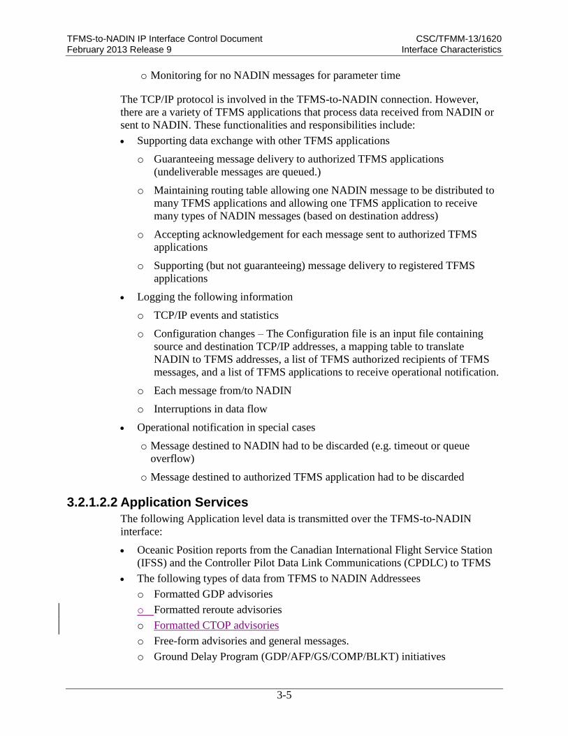
3.2.1.2.2 Application Services
The following Application level data is transmitted over the TFMS-to-NADIN
interface:
Oceanic Position reports from the Canadian International Flight Service Station
(IFSS) and the Controller Pilot Data Link Communications (CPDLC) to TFMS
The following types of data from TFMS to NADIN Addressees
o Formatted GDP advisories
o Formatted reroute advisories
o Formatted CTOP advisories
o Free-form advisories and general messages.
o Ground Delay Program (GDP/AFP/GS/COMP/BLKT) initiatives

TFMS-to-NADIN IP Interface Control Document CSC/TFMM-13/1620 February 2013 Release 9 Interface Characteristics
3-6
ATCSCC advisories and international advisories received via NADIN to the
ATCSCC for electronic logging.
3.2.1.3 Information Units
This subsection describes the formats of the data files transferred between NADIN
and TFMS. The application-level information units that cross this interface consist
only of AFTN messages that are formatted in accordance with the ICAO
Aeronautical Telecommunications Manual, Annex 10, Volume 2 (Amendment 71 or
later). Figure A-1 in Appendix A illustrates the NADIN MSN Application Data
Message Format.
3.2.1.3.1 Information Code
All TFMS-to-NADIN interface messages are encoded in American Standard Code
for Information Interchange (ASCII) alphanumeric data format in accordance with
ANSI X3.4, American National Standard Code for Information Interchange (ASCII),
as described in Section 3.2.1.3.2, and the appropriate subsections.
3.2.1.3.2 Information Structure
Messages exchanged between NADIN and TFMS all follow a consistent format as
illustrated in Table 3-I, Common NADIN Message Format.
The following syntax rules are used for field specifiers in the tables that follow:
L – represents one upper-case letter in ASCII
d – represents one numeric digits in ASCII
n – represents one integer
a – represents one alphanumeric (either number or upper-case letter) in ASCII
[ ] – means the characters enclosed are optional. Any characters not within
brackets are required. For example, Ldd [aa] would indicate an upper-case letter,
followed by two digits, and then zero, one, or two optional alphanumeric
characters.
BOLD indicates a static entry.
Italics indicate that the entry is optional

TFMS-to-NADIN IP Interface Control Document CSC/TFMM-13/1620 February 2013 Release 9 Interface Characteristics
3-7
Table 3-I. Common NADIN Message Format
Field Function Unit/Format Description Bytes
Address Line of Message
Start Start of Message
Header 0x01 Start of Header mandatory
character (ASCII 0x01)
1
Priority Message Priority LL Three characters; two alpha
characters followed by a space
character from the following:
SS – Level 1
DD – Level 2
FF – Level 3
GG – Level 4
JJ – Level 4
KK – Level 4
LL – Level 4
3
Address Destination Address
List
aaaaaaaa
[aaaaaaaa]…[a
aaaaaaa]
Eight characters mandatory
ICAO destination address.
Minimum of one address
needs to be included.
Additional addresses will be
preceded by a space character.
Maximum of seven addresses
per line with a maximum of
three lines of destination
addresses
Each line will end with
Carriage Return (CR ASCII
0x0d) and a Line Feed (LF
ASCII 0x0a)
8-188
End of Address End of Address
Header Fields (CR)(LF)(FS) Markers ending Address
fields:
Carriage Return (CR,
ASCII 0x0d)
Line Feed (LF, ASCII
0x0a)
End of Address (FS,
ASCII 0x1a)
3

TFMS-to-NADIN IP Interface Control Document CSC/TFMM-13/1620 February 2013 Release 9 Interface Characteristics
3-8
Field Function Unit/Format Description Bytes
Origin Line of Message
Timestamp Timestamp of message dddddd Mandatory six numerical
characters field representing
message creation time in UTC,
followed by a space using the
format ddhhmm:
dd – day
hh – hour
mm - minutes
7
Source Source Address aaaaaaaa Eight characters mandatory
ICAO address of message
originator. Each line will end
with Carriage Return (CR
ASCII 0x0d) and a Line Feed
(LF ASCII 0x0a)
8
Message Text of Information Unit Message
Start Start of Text (Stx) Start of text character Stx
(ASCII 0x02)
1
Message Transmitted message ---- See Sections below for
details on the particular
messages transmitted
Each line will end with
Carriage Return (CR ASCII
0x0d) and a Line Feed (LF
ASCII 0x0a); Maximum of
80 characters per line;
Maximum text length of
1800 characters
</=1800
Ending of Message
End of Text End of Text (Vt)(Etx) End of Text characters Vt
(ASCII 0x0b) and Etx (ASCII
0x03). This will follow the
CR, LF of the last line of text.
2

TFMS-to-NADIN IP Interface Control Document CSC/TFMM-13/1620 February 2013 Release 9 Interface Characteristics
3-9
An information unit message is captured in the text field of a NADIN MSN
Message. Table 3-II, TFMS-to-NADIN Interface Information Unit Messages,
presents the TFMS-to-NADIN Interface Information Unit Messages transmitted in
the text field of NADIN Messages, including the subsection reference and
mnemonic.
The maximum text length for the Information Unit Message within a NADIN MSN
Message is 1,800 characters. Information Unit Messages larger than this maximum
will be sent as separate NADIN MSN Messages. The TFMS-to-NADIN interface is
transparent to this segmentation as indicated in Section 3.2.1.3.3.
Table 3-II. TFMS-to-NADIN Interface Information Unit Messages
Product Name Product
Mnemonic ICD Subsection
Fixed Field Position Report POS 3.2.1.3.2.1a
Oceanic Clearance Request Report RCL 3.2.1.3.2.1b
Non-POS/Non-RCL Report 3.2.1.3.2.1c
ATCSCC Advisories 3.2.1.3.2.2
International Advisories 3.2.1.3.2.2
General Message 3.2.1.3.2.2
Formatted Delay Program Advisories – Section 3.2.1.3.2.3 and Appendix B, Section 1.2
Ground Delay Program Advisory – Proposed GDP 3.2.1.3.2.3 and
Appendix B Section 1.2 a
Ground Delay Program Advisory – Actual GDP 3.2.1.3.2.3 and
Appendix B Section 1.2b
Airspace Flow Program Advisory – Proposed AFP 3.2.1.3.2.3 and
Appendix B Section 1.2c
Airspace Flow Program Advisory – Actual AFP 3.2.1.3.2.3 and
Appendix B Section 1.2d
Ground Delay Program Cancel – Proposed GDP CANCEL 3.2.1.3.2.3 and
Appendix B Section 1.2e
Ground Delay Program Cancel – Actual GDP CANCEL 3.2.1.3.2.3 and
Appendix B Section 1.2f
Airspace Flow Program Cancel – Proposed AFP CANCEL 3.2.1.3.2.3 and
Appendix B Section 1.2g
Airspace Flow Program Cancel – Actual AFP CANCEL 3.2.1.3.2.3 and
Appendix B Section 1.2h
Ground Stop Advisory – Proposed GS 3.2.1.3.2.3 and
Appendix B Section 1.2i
Ground Stop Advisory – Actual GS 3.2.1.3.2.3 and
Appendix B Section 1.2j

TFMS-to-NADIN IP Interface Control Document CSC/TFMM-13/1620 February 2013 Release 9 Interface Characteristics
3-10
Product Name Product
Mnemonic ICD Subsection
Ground Stop Cancel – Proposed GS CANCEL 3.2.1.3.2.3 and
Appendix B Section 1.2k
Ground Stop Cancel – Actual GS CANCEL 3.2.1.3.2.3 and
Appendix B Section 1.2l
Ground Delay Program/Airspace Flow Program
Compression – Proposed
GDP/AFP
COMPRESSION
3.2.1.3.2.3 and
Appendix B Section 1.2m
Ground Delay Program/Airspace Flow Program
Compression – Actual
GDP/AFP
COMPRESSION
3.2.1.3.2.3 and
Appendix B Section 1.2n
Ground Delay Program Blanket Advisory – Proposed GDP BLANKET 3.2.1.3.2.3 and
Appendix B Section 1.2o
Ground Delay Program Blanket Advisory – Actual GDP BLANKET 3.2.1.3.2.3 and
Appendix B Section 1.2p
Formatted Reroute Advisory – Section 3.2.1.3.2.4
Formatted Reroute Advisory 3.2.1.3.2.4 and
Appendix B Section 1.3
Formatted CTOP Advisories – Section 3.2.1.3.2.5
CTOP Advisory– Proposed N/A 3.2.1.3.2.5 and
Appendix B Section 1.4 -
a
CTOP Advisory– Actual N/A 3.2.1.3.2.5 and
Appendix B Section 1.4 -
b
CTOP Cancel– Actual N/A 3.2.1.3.2.5 and
Appendix B Section 1.4 -
c
Unsolicted Messages – Section 3.2.1.3.2.6
Slot List N/A 3.2.1.3.2.6.1
GDP Termination N/A 3.2.1.3.2.6.2
Substitution Message N/A 3.2.1.3.2.6.3
3.2.1.3.2.1 Oceanic Position Report
There are three types of Oceanic Position Reports described in this section, identified
by the 3-character standard message ID (SMI) field in the case of the first two
message types, or by a designated token in the third instance:
Fixed Field Position Report (POS)
Oceanic Clearance Request Report (RCL)
Non-POS and Non-RCL Report (Token-indicated)

TFMS-to-NADIN IP Interface Control Document CSC/TFMM-13/1620 February 2013 Release 9 Interface Characteristics
3-11
a. Fixed Field Position Report (POS)
The “POS” character sequence indicates a fixed field position report. This type of
position report begins and ends in round brackets – ( ) – and is indicated by the
keyword “POS”. It is terminated with a carriage return (CR). There are three possible
formats in which the POS message will be represented:
1. Position – Altitude – Position
2. Altitude – Position – Position
3. Position – Position - Altitude
The syntax of a fixed field position report is as follows:
Sample Fixed Field Position (POS) Report
Format 1:
(POS-<acid>-<pos1>/<eta1> [Letter]<alt> <pos2>/<eta2> NEXT <pos3>/<eta3>-CR
[other data]CR)
Format 2:
(POS-<acid>-[Letter]<alt> <pos1>/<eta1> <pos2>/<eta2> NEXT <pos3>/<eta3>-CR
[other data]CR)
Format 3:
(POS-<acid>-<pos1>/<eta1> <pos2>/<eta2> [Letter]<alt> NEXT <pos3>/<eta3>-CR
[other data]CR)(POS-DAL125-47N50W/1500 F350 RONPO/1506 NEXT COLOR–{CR}
FUEL 58.7{CR}
CYQXR 13205{CR}
1269/AT/82/15000{CR}
In the example of the Format 1 above, the following fields are detailed:
(POS – Indicates this message is a POS report
-DAL125 - <acid> The aircraft identifier
-47N50W – Aircraft position, in this instance, a lat/long pair
/1500 – Time over this position
[space]
F350 – Altitude at this position. Preceded by an “F” (which is not used by
TFMS)
[space]
RONPO – Position fix name
/1506 – Time of this position fix
NEXT – Indicates there is a third position fix. This fix is optional.
[space]

TFMS-to-NADIN IP Interface Control Document CSC/TFMM-13/1620 February 2013 Release 9 Interface Characteristics
3-12
COLOR - Position fix name
- - Indicates no fix time entered.
The format of the POS report is described in Table 3-III.
Table 3-III. Fixed Field Position (POS) Report
Field Function Unit/Format Description Bytes
POS Message Type Identifier POS Three letters, fixed field –
“POS” (Static entry)
3
acid Aircraft Identifier La[a][a][a][a]
[a]
2 to 7 characters in length with
first character being an
uppercase letter.
2 - 7
pos1 Initial Position Fix ddddL/dddddL
or
LLLLL
Fix represented as
latitudes/longitudes pairs or fix
names.
5 - 12
eta1 Initial Position
Estimated Time of
Arrival
dddd Estimated time of arrival
(ETA) for the Initial Position
Fix. The ETA is a 4-digit
number representing hours and
minutes (hhmm). The first two
digits represent the hour and
must be between 00 to 23. The
last two digits represent the
minute and must be between
00 to 59. An invalid time is
ignored.
4
[space] Spacer Provides a break between
entries
1
alt1 Initial Position Altitude Lddd[d][d][d]
[d][d]
The Initial Position Altitude is
a numeric value between 3 and
8 digits. This entry is preceded
by a single letter (A, C, D, F,
or L), which is not used in
processing to the TO message.
4-9
[space] Spacer Provides a break between
entries
1
pos2 Second Position Fix ddddL/dddddL
or
LLLLL
Fix represented as
latitudes/longitudes pairs or fix
names.
5 - 12
eta2 Second Position
Estimated Time of
Arrival
dddd Estimated time of arrival
(ETA) for Second Position Fix.
This follows the same rules as
above.
4
[space] Spacer Provides a break between
entries
1

TFMS-to-NADIN IP Interface Control Document CSC/TFMM-13/1620 February 2013 Release 9 Interface Characteristics
3-13
Field Function Unit/Format Description Bytes
NEXT Indicator - Third
Position Fix NEXT Static Entry: NEXT 4
[space] Spacer Provides a break between
entries
1
pos3 Third Position Fix ddddL/dddddL
or
LLLLL
Fix represented as
latitudes/longitudes pairs or fix
names.
5 - 12
eta3 Third Position Estimated
Time of Arrival
dddd Estimated time of arrival
(ETA) for Third Position Fix.
This follows the same rules as
above.
4
CR Carriage Return -- --
Other Data Data not used by TFMS Variable amount of data used
by other systems, but not
utilized by TFMS.
CR Carriage Return -- --
b. Oceanic Clearance Request (RCL)
This character sequence indicates an Oceanic Clearance Request. This is processed
the same way as a “POS” message, except for a possible altitude entry defined at the
end (“_alt”). If this occurs, this altitude value will replace the previous one. The
syntax of an RCL report is as follows:
Sample Oceanic Clearance (RCL) Request
(RCL-<acid>-<pos1>/<eta1> F<alt> <pos2>/<eta2> NEXT <pos3>/<eta3> [letter]<_alt>-CR…)CR
(RCL-DAL125-47N50W/1500 F350 RONPO/1506 NEXT COLOR/1513 F390{CR}
FUEL 58.7{CR}
CYQXR 13205{CR}
1269/AT/82/15000{CR}
In the example above, the following fields are detailed:
(RCL – Indicates this message is a RCL report
-DAL125 - <acid> The aircraft identifier
-47N50W – Aircraft position, in this instance, a lat/long pair
/1500 – Time over this position
[space]
F350 – Altitude at this position. Preceded by an “F” (which is not used by
TFMS)

TFMS-to-NADIN IP Interface Control Document CSC/TFMM-13/1620 February 2013 Release 9 Interface Characteristics
3-14
[space]
RONPO – Position fix name
/1506 – Time of this position fix
NEXT – Indicates there is a third position fix. This fix is optional.
[space]
COLOR - Position fix name
/1513 - Time of this position fix
F390 – Indicates new altitude defined at this position fix
The format of the RCL report is described in Table 3-IV.
Table 3-IV. Oceanic Clearance Request Report (RCL)
Field Function Unit/Format Description Bytes
RCL Message Type Identifier RCL Three letters, fixed field –
“RCL” (Static entry)
3
acid Aircraft Identifier La[a][a][a][a]
[a]
2 to 7 characters in length with
first character being an
uppercase letter.
2 - 7
pos1 Initial Position Fix ddddL/dddddL
or
LLLLL
Fix represented as
latitudes/longitudes pairs or fix
names.
5 - 12
eta1 Initial Position
Estimated Time of
Arrival
dddd Estimated time of arrival
(ETA) for the Initial Position
Fix. It is a 4-digit number
representing hours and minutes
(hhmm). The hour must be
between 00 and 23. The minute
must be between 00 and 59. An
invalid time is ignored.
4
[space] Spacer Provides a break between
entries
1
alt1 Initial Position Altitude Lddd[d][d][d]
[d]
The Initial Position Altitude is
a numeric value between 3 and
8 digits. This entry is preceded
by a single letter (A, C, D, F,
or L), which is not used in
processing to the TO message.
4-9
[space] Spacer Provides a break between
entries
1
pos2 Second Position Fix ddddL/dddddL
or
LLLLL
Fix represented as
latitudes/longitudes pairs or fix
names.
5 - 12

TFMS-to-NADIN IP Interface Control Document CSC/TFMM-13/1620 February 2013 Release 9 Interface Characteristics
3-15
Field Function Unit/Format Description Bytes
eta2 Second Position
Estimated Time of
Arrival
dddd Estimated time of arrival
(ETA) for Second Position Fix.
This follows the same rules as
above.
4
[space] Spacer Provides a break between
entries
1
NEXT Indicator - Third
Position Fix NEXT Static Entry: NEXT 4
[space] Spacer Provides a break between
entries
1
pos3 Third Position Fix ddddL/dddddL
or
LLLLL
Fix represented as
latitudes/longitudes pairs or fix
names.
5 - 12
eta3 Third Position Estimated
Time of Arrival
dddd Estimated time of arrival
(ETA) for Third Position Fix.
This follows the same rules as
above.
4
CR Carriage Return -- --
alt3 Third Position Altitude Lddd[d][d][d]
[d]
The Third Position Altitude is a
numeric value between 3 and 8
digits. This entry is preceded
by a single letter (A, C, D, F,
or L), which is not used in
processing to the TO message.
4-9
Other Data Data not used by TFMS Variable amount of data used
by other systems, but not
utilized by TFMS.
CR Carriage Return -- --
c. Non-POS and Non-RCL Type Messages
The oceanic message received may not be either a POS or RCL report. Non-
POS/Non-RCL messages do not follow a set format, as the previous Oceanic
Position reports did. Instead, they are comprised of various Keyword tokens. These
Keyword tokens are examined and used as a processing guide. When processing the
Non-POS/Non-RCL message, the system follows the following procedure:
The first Keyword token in the message is examined by an internal process called
the Offshore Message Processor (OMP)1 and parsed if it meets the following
defined conditions:
o The first Keyword token in not an “FI” (see below)
1 The Offshore Message Processor is fully described in the Volpe document VNTSCD-TFM-ICD-OMP-001
Offshore Message Processor: Interface Control Document.

TFMS-to-NADIN IP Interface Control Document CSC/TFMM-13/1620 February 2013 Release 9 Interface Characteristics
3-16
o The first Keyword token matches one of the token listed in the ‘dots_smi”
file (see below)
If the first Keyword token does not match either of these, then the message is
ignored.
Once the initial conditions for the message are met, the message is processed
further by examining Keyword tokens, until one of the following occurs:
o An error is encountered (garble, invalid data, etc.)
o There are no more Keyword tokens
o There is sufficient data to construct the TO message
o The Keyword token “DT” is encountered, indicating the end of the
message.
The following shows the typical syntax of non-POS and non-RCL position report
messages and a sample (sample broken down by entry in Table 3-V):
Sample Non-POS and Non-RCL Report
<SMI_keyword>CR
FI <acid>/[tok1] <pos1> <eta1> <alt1>/[tok2] <pos2> <eta2> <alt2>/[tok3] <pos3> <eta3> <alt3>CR
/[tok] <data>/{tok] <data> (etc)CR
DT <other data>CR
CR
POS(Cr)
FI AJX1052/OV 33N 170E 1459 F380/EO 30N 180W 1604/NP TALON(Cr)
TA MS58/WV 310045/FB 528/TB CODE O1C(Cr)
DT SFO SC B 151500 12 (Cr)
(Cr)
In the example above, the following fields are detailed (Note – the entries in italics
are not processed by TFMS, and are simply ignored by the system):
POS – Indicates this message is a position report (differentiated from the
standard POS message by the fields following)
Carriage Return
AJX1052 – <acid> The aircraft identifier
/OV 33N 170E 1459 F380 – <tok1> <pos1> <eta1> <alt1> – Aircraft current
position (in this instance, a lat/long pair), Time, and Flight Level in thousands of
feet
/EO 30N 180W 1604 – <tok2> <pos2> <eta2> Estimated To Be Over a Position ,
(in this instance, a lat/long pair), at a Designated Time, and Flight Level in
thousands of feet
/NP TALON – <tok> <data> - Next Position (In this case, a Fix Name)

TFMS-to-NADIN IP Interface Control Document CSC/TFMM-13/1620 February 2013 Release 9 Interface Characteristics
3-17
Carriage Return
TA MS58 – <tok> <data> Static Air Temperature (in degrees Celsius)
/WV 310045 – <tok> <data> Wind direction and speed at flight level
/FB 528 – <tok> <data> Fuel on Board (in pounds)
/TB CODE 01C – <tok> <data> Turbulence (in coded figure)
Carriage Return
DT SFO SC B 151500 12 – <DT <other data> Position Report terminator. All
data beyond the letters “DT” is ignored by TFMS.
Carriage Return
Carriage Return
The format of the Non-POS, Non-RCL message is described in Table 3-V.
Table 3-V. Non-POS, Non-RCL Message
Field Function Unit/Format Description Bytes
SMI SMI Keyword LLL Keyword indicating the type of
message following. See Table
3-V for full breakout.
3
/FI Aircraft Identifier /FI Ld[d][d][d]
[d][d]
The FI field defines the aircraft
ID (ACID).
It must be two to seven
characters in length. The first
character must be an uppercase
letter, with all other characters
uppercase letters or numbers.
The ACID is stored in the
“acid” field of the flight record.
Any errors in this entry will
result in the flight record being
invalid.
6-11
/OV Present Location /OV
ddL[]dddL
dddd
[FL][A][ddd]
(For lat long
entries)
or
/OV LLLLL
dddd
[FL][A][ddd]
(for name
string entries)
The OV field defines
information for the first fix
(present location). The position
is processed, either as a single
name string or a lat/long pair.
If given as a lat/long pair, it
can be values separated by a
space or no space. The position
is stored into the “pos1” field
of the flight record.
The ETA is given as a 4-digit
time and defined as hhmm
where “hh” are hours from 0 to
23 and “mm” are minutes from
14-23

TFMS-to-NADIN IP Interface Control Document CSC/TFMM-13/1620 February 2013 Release 9 Interface Characteristics
3-18
Field Function Unit/Format Description Bytes
00 to 59. The ETA is stored in
the “eta1” field of the flight
record.
The altitude is optional and is
parsed by removing the “A” or
“F” preceding the entry. It is
stored in the “alt1” field of the
flight record.
/EO Estimated To Be Over a
Position at a Time /EO
ddL[]dddL
dddd
(For lat long
entries)
or
/EO LLLLL
dddd
(for name
string entries)
The EO field defines
information for the second fix,
(second position).
The position is processed,
either as a single name string
or a lat/long pair. If given as a
lat/long pair, it can be values
separated by a space or no
space. The position is stored
into the “pos2” field of the
flight record.
The ETA is given as a 4-digit
time and defined as hhmm
where “hh” are hours from 0 to
23 and “mm” are minutes from
00 to 59. The ETA is stored in
the “eta2” field of the flight
record.
15-17
/NP /NP
ddL[]dddL
(For lat long
entries)
or
/NP LLLLL
(for name
string entries)
The NP field defines
information for the third fix,
(last position). The position is
processed, either as a single
name string or a lat/long pair.
If given as a lat/long pair, it
can be values separated by a
space or no space. The position
is stored into the “pos3” field
of the flight record.
9-12
/DA Departure Aerodrome /DA aaa[a] The DS field defines the
departure airport.
The name must be either 3 or 4
characters in length.
This is stored in the “dept”
field of the flight record. Any
errors in this entry will result in
the flight record being invalid.
7-8
/DS Destination Aerodrome /DS aaa[a]
[dddd]
The DS field defines the
destination aerodrome. The
name must be either 3 or 4
7-13

TFMS-to-NADIN IP Interface Control Document CSC/TFMM-13/1620 February 2013 Release 9 Interface Characteristics
3-19
Field Function Unit/Format Description Bytes
characters in length. This is
stored in the “dest” field of the
flight record.
An estimated time of arrival
(ETA) is optional in this case.
The ETA is defined as (hhmm)
where “hh” are hours from 0 to
23 and “mm” are minutes from
00 to 59.
This ETA value is stored in the
“dest_eta” field of the flight
record. Any errors in this entry
will result in the flight record
being invalid.
/OF Time Off /OF dddd The OF field defines the
departure field time. A valid
time must be 4 digits in the
form (hhmm) where “hh” are
hours from 00 to 23 and “mm”
are minutes from “00” to
“59”.
The time value is stored in the
“dept_Time” field of the flight
record. An invalid time is
ignored.
8
/DT Position Report
Terminator
/DT * The DT field signifies the end
of the message. Everything
after this is ignored by OMP,
which proceeds with the
creation of the TO message
based on all of the data
gathered.
Vrbl
Note – There are five additional tokens which may appear, but are not processed by the system:
/TA - Static Air Temperature
/WV - Wind Information
/WX - Weather
/FB - Fuel On Board
/TB – Turbulence
Refer to VNTSCD-TFM-ICD-OMP-001 for details on these entries.
Table 3-VI shows the “dots_smi” file that defines the valid SMIs. Any other entry in
the SMI Keyword position will be rejected.

TFMS-to-NADIN IP Interface Control Document CSC/TFMM-13/1620 February 2013 Release 9 Interface Characteristics
3-20
Table 3-VI. “dots_smi” Keywords File
SMI *SMI
Number* REPORT TYPE
AEP 01 Position With Weather
AGM 07 Miscellaneous Air/Ground Message
AID 36 Airborne Instrumentation Data System
ALR 05 Alerting Message
ARI 40 Fuel/Close-Out Report
ARR 04 Arrival
AVR 19 Air Crew Originated Voice Request
CHO 15 Changeover Or In-Range Report
CLK 20 Airborne GMT Clock Reset
CLR 08 Flight Clearance
CMD 26 ACARS Avionics Memory Load Or Diagnostic Function
CNL 13 Cancellation Of Flight
CPL 10 Current Flight Plan
DEP 03 Departure
DFD 35 ACARS Digital Flight Data Acquisition Unit
DIV 41 Aircraft Diversion Message
DLA 12 Flight Delay
ENG 38 Aircraft Engine Data
ETA 17 Estimated Time Of Arrival
ETR 32 Aircrew Initiated Revision To Previously Advised Estimated
Time Of Arrival
FAM 14 Flight Movement Advisory Message
FML 33 ACARS Flight Management Computer - Left
FMR 34 ACARS Flight Management Computer - Right
FPL 09 Filed Flight Plan
FPR 24 Aircraft Originated Request For Flight Plan Update Via ACARS
FPU 23 Ground Originated Flight Plan Update To Aircraft Via ACARS
GVR 18 Ground Originated Voice Request
HJK 39 Aircraft Hijacked
LIF 22 Ground Originated Aircraft Load Information
MVT 16 Flight Movement
OAT 21 Airborne Optional Auxiliary Data Terminal/Device
PDM 42 Possible Duplicate Message
POS 02 Position Without Weather

TFMS-to-NADIN IP Interface Control Document CSC/TFMM-13/1620 February 2013 Release 9 Interface Characteristics
3-21
SMI *SMI
Number* REPORT TYPE
PSN 10 Aircrew Initiated Position Report With/Without Weather
Information
RDO 25 ACARS Avionics Memory Readout
RTN 29 ACARS Equipped Aircraft Return To Gate
SPL 11 Supplemental Flight Plan
SVC 37 ACARS Communications Service Message
THR 31 Air Crew Initiated Or Auto Sensed Take Off Thrust
TIS 06 Airport Terminal Information Service
WXO 28 Weather Observation Report
WXR 27 Weather Observation Request
*Note – SMI Number is not used by the system.
3.2.1.3.2.2 Free-Formatted Advisories and General Messages
A free-formatted advisory is an advisory message that is disseminated electronically
by the ATCSCC, International systems, or other originators. An advisory contains
information pertaining to the National Airspace System, and are normally used for
the following reasons:
Route and enroute information
Planning Telcon (PT) advisories
Facility outages
Special Traffic Management Programs (STMP)
This list is not all-inclusive. Any time there is information that may be beneficial to a
large number of customers, an advisory may be sent. There may be times when an
advisory is not sent due to workload or the short duration of the activity.
ATCSCC uses free form advisories to pass important information on a variety of
items. While these messages are free text, they do follow a designated header and
signature information pattern. The detailed descritiption of ATCSCC free from
advisory is presented in Appendix B.
3.2.1.3.2.3 Formatted GDP Advisory
Formatted GDP advisories are used to notify users that a Ground Delay Program is
being considered or has been implemented. There are 16 advisories described in this
section:
Ground Delay Program (GDP) Advisory – Proposed
Ground Delay Program (GDP) Advisory – Actual
Airspace Flow Program (AFP) Advisory – Proposed
Airspace Flow Program (AFP) Advisory – Actual
Ground Delay Program (GDP) Cancel – Proposed

TFMS-to-NADIN IP Interface Control Document CSC/TFMM-13/1620 February 2013 Release 9 Interface Characteristics
3-22
Ground Delay Program (GDP) Cancel – Actual
Airspace Flow Program (AFP) Cancel – Proposed
Airspace Flow Program (AFP) Cancel – Actual
Ground Stop (GS) Advisory – Proposed
Ground Stop (GS) Advisory – Actual
Ground Stop (GS) Cancel – Proposed
Ground Stop (GS) Cancel – Actual
Ground Delay Program/Airspace Flow Program (GDP/AFP) Compression –
Proposed
Ground Delay Program/Airspace Flow Program (GDP/AFP) Compression –
Actual
Ground Delay Program (GDP) Blanket Advisory – Proposed
Ground Delay Program (GDP) Blanket Advisory – Actual
Since advisories are in some cases transmitted as IATA Type B messages, the
following restrictions of this message type apply to the formatted GDP advisories:
A maximum of 68 upper case alphanumeric characters per line
Only the “/”, “-“, and “.” Punctuations
Text must be positioned using spaces, no tabs are permitted.
The above types of formatted GDP advisories are discussed in detail in Appendix B.
3.2.1.3.2.4 Formatted Reroute Advisory
Description of the Reroute Advisory message contained in this section is extracted
from the FAA Order 7210.3U, Facility Operations and Administration, Section 17,
February 16, 2006. Note – Any spaces contained in a line are included in the byte
counts. Appendix Bprovides details of this message.
3.2.1.3.2.5 Formatted CTOP Advisories
Formatted CTOP advisories are used to notify users that a Collaborative Trajectory
Options Program is being considered or has been implemented. There are 3
advisories described in this section:
Collaborative Trajectory Options Program (CTOP) Advisory – Proposed
Collaborative Trajectory Options Program (CTOP) Advisory – Actual
Collaborative Trajectory Options Program (CTOP) Cancel – Actual
All advisories contain an additional line with the date, time, desk location, and phone
number of the workstation that transmitted the advisory. This line, added during the
advisory transmission process, is not depicted in the samples provided in this
document because it is a transmission addendum and is not related to the primary
purpose of the advisory.
Since advisories are in some cases transmitted as IATA Type B messages, the
following restrictions of this message type apply to the formatted CTOP advisories:
A maximum of 68 upper case alphanumeric characters per line are permitted
TFMS-to-NADIN IP Interface Control Document CSC/TFMM-13/1620 February 2013 Release 9 Interface Characteristics
3-23
Only the “/”, “-“, and “:” Punctuations are permitted
Text must be positioned using spaces, no tabs are permitted.
The above types of formatted CTOP advisories are discussed in detail in Appendix
B.
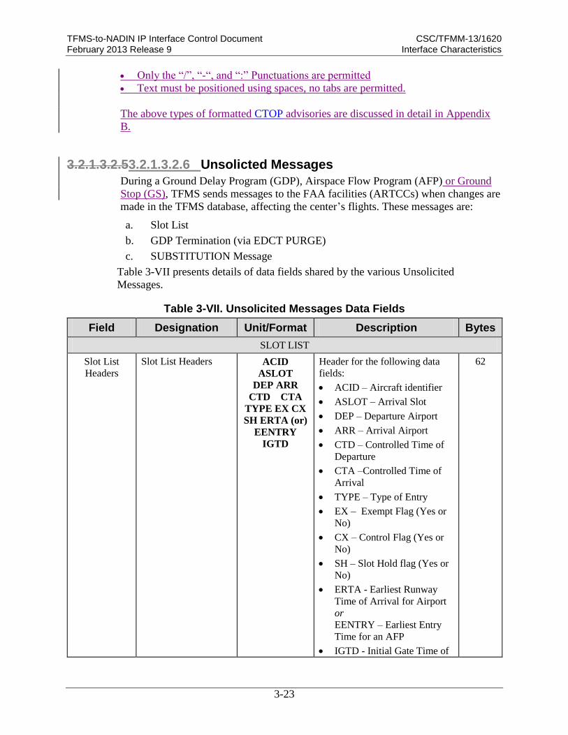
3.2.1.3.2.53.2.1.3.2.6 Unsolicted Messages
During a Ground Delay Program (GDP), Airspace Flow Program (AFP) or Ground
Stop (GS), TFMS sends messages to the FAA facilities (ARTCCs) when changes are
made in the TFMS database, affecting the center’s flights. These messages are:
a. Slot List
b. GDP Termination (via EDCT PURGE)
c. SUBSTITUTION Message
Table 3-VII presents details of data fields shared by the various Unsolicited
Messages.
Table 3-VII. Unsolicited Messages Data Fields
Field Designation Unit/Format Description Bytes
SLOT LIST
Slot List
Headers
Slot List Headers ACID
ASLOT
DEP ARR
CTD CTA
TYPE EX CX
SH ERTA (or)
EENTRY
IGTD
Header for the following data
fields:
ACID – Aircraft identifier
ASLOT – Arrival Slot
DEP – Departure Airport
ARR – Arrival Airport
CTD – Controlled Time of
Departure
CTA –Controlled Time of
Arrival
TYPE – Type of Entry
EX – Exempt Flag (Yes or
No)
CX – Control Flag (Yes or
No)
SH – Slot Hold flag (Yes or
No)
ERTA - Earliest Runway
Time of Arrival for Airport
or
EENTRY – Earliest Entry
Time for an AFP
IGTD - Initial Gate Time of
62

TFMS-to-NADIN IP Interface Control Document CSC/TFMM-13/1620 February 2013 Release 9 Interface Characteristics
3-24
Field Designation Unit/Format Description Bytes
Departure
SLOT LIST DATA FIELDS*
ACID Flight Identification Laa[a][a][a][a] Flight call sign as it appears in
the OAG and/or subsequently
will be filed on the NAS flight
plan. Padded with spaces to
equal 8 bytes.
8
ASLOT Arrival Slot LLL[Laa].dddd
ddL
The time slot reserved at the
airport or FCA for this flight to
arrive as follows:
Name – airport or FCA
name. An airport name can
be three or four characters
and can include letters and
numbers. An FCA name
must be the entry FCA
followed by three
alphanumeric characters.
The name is separated from
the Date/Time by a period
for readability
Date/Time – Slot date and
time. The format is
DDhhmm (padded as
necessary)
Suffix Letter - The suffix
letter is used to ensure that
slot name is unique.
Note - An FCA name must be
six characters starting with the
literal letters “FCA”. The
remaining characters can be
either digits, upper-case letters,
dash (“-“), or underscore (“_”).
An FCA name cannot end with
an underscore. Padded with
spaces to equal 15 bytes.
15
DEP Departure Airport LLL[L] Departure airport code in
standard 3 or 4 letter identifier,
padded with spaces to equal 5
bytes
5

TFMS-to-NADIN IP Interface Control Document CSC/TFMM-13/1620 February 2013 Release 9 Interface Characteristics
3-25
Field Designation Unit/Format Description Bytes
ARR Arrival Airport LLL[L] Arrival airport code in standard
3 or 4 letter identifier, padded
with spaces to equal 5 bytes.
Note - For a GDP, the arrival
airport will be the same for
every flight; for an AFP, they
may differ. It is padded with
spaces to equal 5 bytes
5
CTD Controlled Time of
Departure
dddddd The time the flight should take
off. In the format DDhhmm,
padded with spaces to equal 7
bytes
7
CTA Controlled Time of
Arrival
dddddd The time the flight should arrive
at the controlled airport or FCA
(e.g., 260400). In the format
DDhhmm, padded with spaces
to equal 7 bytes
7
TYPE
Control Type LLL[L] The source of the current control
times for this flight (e.g. GDP).
The control types that can
appear in a slot list are:
ABRG – the flight was
utilized to create a bridge in
order to adaptive compress a
slot.
ADPT – control time
assigned when the flight was
adaptively compressed by
the TFMS adaptive
compression process (AFP
and GDP)
AFP – Control times were
computed as part of an
initial AFP, a revision to an
AFP, or an extension to an
AFP.
BLKT – Control times were
computed by a blanket
program.
COMP – Control times were
computed by compression.
DAS – Control time which
resulted from the
assignment of the average
delay to a pop-up flight
which did not receive an
unassigned slot in an AFP or
5

TFMS-to-NADIN IP Interface Control Document CSC/TFMM-13/1620 February 2013 Release 9 Interface Characteristics
3-26
Field Designation Unit/Format Description Bytes
GDP. For DAS based
programs this is used for the
initial delay assignments to
all pop-up flights. For
GAAP and UDP based
programs, this control type
is used only if no
unassigned slot is available
for the pop-up. This control
type is not used for re-
controlled flights. (AFP and
GDP)
ECR – Control times were
assigned by an FAA ECR
request.
GAAP – control times are
the result of a GAAP or
UDP based AFP or GDP if a
pop-up or a re-control flight
is allocated to an unassigned
slot. This occurs for all pop-
up flights in a GAAP or
UDP based program when
an unassigned slot is
available for the flight.
However, only some classes
of re-controlled flights in a
GAAP or UDP are assigned
to unassigned slots. (e.g.,
those that occur after
dropping out of an AFP).
(AFP and GDP)
GDP – Control times were
computed as part of an
initial GDP, a revision to a
GDP, or an extension to a
GDP.
GS – Control times were
computed by a ground stop.
RCTL – control time which
resulted from the
assignment of the average
delay to a flight that was at
some point controlled by a
GDP or AFP, which was
then purged or the flight
dropped out and was re-
controlled in another AFP.

TFMS-to-NADIN IP Interface Control Document CSC/TFMM-13/1620 February 2013 Release 9 Interface Characteristics
3-27
Field Designation Unit/Format Description Bytes
For DAS programs this is
used for the initial delay
assignments to all re-
controlled flights. For
GAAP and UDP, this
control type is used only if
no unassigned slot is
available for the re-
controlled flight or the class
of re-controlled flight is
never assigned to
unassigned slots. As
opposed to other pop-ups,
RCTL flights retain full
substitution rights (AFP)
SBRG – Control times were
assigned when creating a
bridge for an SCS or ECR
request.
SCS – Control times were
assigned by a user slot credit
substitution message.
SUB – Control times were
assigned by a conventional
user substitution message.
UBRG – Control times
assigned when creating a
bridge for pop-up flight
assignments during UDP.
Performed automatically by
the TFMS-Core (AFP and
GDP)
UPD – Control times are
from an FAA “EDCT
UPDATE” command.
This entry is padded with spaces
to equal 5 bytes.
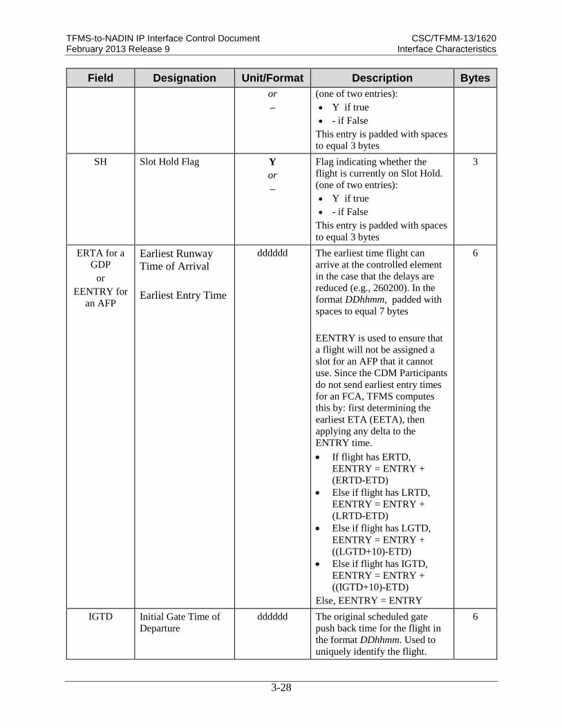
EX Exempt Flag Y
or
–
Flag indicating flight was
exempt from delays when the
GDP or AFP was computed.
(one of two entries):
Y if true
- if False
This entry is padded with spaces
to equal 3 bytes
3
CX Cancel Flag Y Flag indicating whether the
flight is currently cancelled.
3
TFMS-to-NADIN IP Interface Control Document CSC/TFMM-13/1620 February 2013 Release 9 Interface Characteristics
3-28
Field Designation Unit/Format Description Bytes
or
–
(one of two entries):
Y if true
- if False
This entry is padded with spaces
to equal 3 bytes
SH Slot Hold Flag Y
or
–
Flag indicating whether the
flight is currently on Slot Hold.
(one of two entries):
Y if true
- if False
This entry is padded with spaces
to equal 3 bytes
3
ERTA for a
GDP
or
EENTRY for
an AFP
Earliest Runway
Time of Arrival
Earliest Entry Time
dddddd The earliest time flight can
arrive at the controlled element
in the case that the delays are
reduced (e.g., 260200). In the
format DDhhmm, padded with
spaces to equal 7 bytes
EENTRY is used to ensure that
a flight will not be assigned a
slot for an AFP that it cannot
use. Since the CDM Participants
do not send earliest entry times
for an FCA, TFMS computes
this by: first determining the
earliest ETA (EETA), then
applying any delta to the
ENTRY time.
If flight has ERTD,
EENTRY = ENTRY +
(ERTD-ETD)
Else if flight has LRTD,
EENTRY = ENTRY +
(LRTD-ETD)
Else if flight has LGTD,
EENTRY = ENTRY +
((LGTD+10)-ETD)
Else if flight has IGTD,
EENTRY = ENTRY +
((IGTD+10)-ETD)
Else, EENTRY = ENTRY
6
IGTD Initial Gate Time of
Departure
dddddd The original scheduled gate
push back time for the flight in
the format DDhhmm. Used to
uniquely identify the flight.
6

TFMS-to-NADIN IP Interface Control Document CSC/TFMM-13/1620 February 2013 Release 9 Interface Characteristics
3-29
Field Designation Unit/Format Description Bytes
*Note – There may be multiple rows of data under the header.
3.2.1.3.2.5.1 Slot List
When a GDP, GS or AFP is initially issued or revised or when controlled flight
departure times change as a result of adaptive compression, substitution, or Traffic
Manager EDCT overrides, slot lists are organized by departure center and distributed
to the affected Departure Centers. The slot lists provide a list of the controlled flights
involved in the GDP, GS, or AFP for that departure center, including flights that have
been cancelled. When the program is issued or revised, the slot list contains a
complete list of all controlled flights departing from the center. Otherwise, the slot
list contains the list of flights that are affected by the event which caused the message
to be sent. A sample Slot List message for an ARTCC has the following format:
Sample Slot List for a GDP
DEP CNTR ZDC
ACID ASLOT DEP ARR CTD CTA TYPE EX CX SH ERTA IGTD
ABC1234 LGA.260400A DCA LGA 260300 260400 GDP - - - 260400 260245
ABC5678 LGA.260500A IAD LGA 260400 260500 GDP - - - 260300 260145
ABC3601 LGA.260323A BOS LGA 260206 260323 GDP Y - - 260319 260150
ABC3522 LGA.260311A DCA LGA 260215 260311 GDP - - - 260311 260145
ABC3994 LGA.260353A ROC LGA 260246 260353 GDP - Y - 260355 260235
Table 3-VII presents a breakout of the Slot List Headers and Data Fields shown
above
3.2.1.3.2.5.2 GDP Termination (via EDCT Purge)
The FAA terminates a GDP by using an EDCT PURGE command to clear the
controls out of the TFMS database. Each departure center gets a copy of the EDCT
PURGE command along with a Slot List of the affected flights (i.e., the flights no
longer controlled by the terminated delay program) departing from it. A sample
EDCT PURGE message follows:
Sample EDCT Purge Message (for an FCA)
EDCT PURGE FCAA02
ACID ASLOT DEP ARR CTD CTA TYPE EX CX SH EENTRY IGTD
ABC1234 FCAA02.260400A DCA LGA 260300 260400 AFP - - - 260400 260245
ABC5678 FCAA02.260500A DCA BOS 260400 260500 AFP - - - 260300 260145
ABC360 FCAA02.260323A DCA LGA 260206 260323 AFP Y - - 260319 260150
ABC3522 FCAA02.260311A DCA BOS 260215 260311 AFP - - - 260311 260145
ABC39 FCAA02.260353A DCA LGA 260246 260353 AFP - Y - 260355 260235
Table 3-VIII below presents a breakout of the EDCT Purge Message.

TFMS-to-NADIN IP Interface Control Document CSC/TFMM-13/1620 February 2013 Release 9 Interface Characteristics
3-30
Table 3-VIII. EDCT Purge Message
Field/Line Designation Unit/Format Description Bytes
1 EDCT Purge
Identifier EDCT PURGE
FCAaaa
or
EDCT PURGE
aaa
Identifies airport or FCA that the
EDCT Purge is for.
14-17
2
Slot List Data
Headers ACID
ASLOT
DEP ARR
CTD CTA
TYPE EX CX
SH ERTA (or)
EENTRY
IGTD
Header for the following data
fields:
ACID – Aircraft identifier
ASLOT – Arrival Slot
DEP – Departure Airport
ARR – Arrival Airport
CTD – Controlled Time of
Departure
CTA –Controlled Time of
Arrival
TYPE – Control Type
EX – Exempt Flag (Yes or
No)
CX – Control Flag (Yes or
No)
SH – Slot Hold Flag (Yes or
No)
ERTA – Earliest Runway
Time of Arrival
or
EENTRY – Earliest Entry
Time
IGTD - Initial Gate Time of
Departure
65
3 - n Slot List Data Fields Refer to Table 3-VII for detailed
breakout.
3.2.1.3.2.5.3 Substitution Message
When a user successfully substitutes flights, TFMS sends a response confirming the
new control times for those flights. The person who generated request, and/or the
application from which the request was sent, therefore know that these flights have
been updated. However, other people from that user’s organization and other
applications the user may run do not necessarily know that these flights have
changed. In order to allow a person or application to have a single source of all
control time changes, TFMS sends an unsolicited message to each departure center

TFMS-to-NADIN IP Interface Control Document CSC/TFMM-13/1620 February 2013 Release 9 Interface Characteristics
3-31
affected by a successful substitution request. The message includes a list of the
affected flights departing from the center.
A sample SUBSTITUTION message for a user has the following format:
Sample SUBSTITUTION Message (for a GDP)
SUBSTITUTION FOR LGA
ACID ASLOT DEP ARR CTD CTA TYPE EX CX SH ERTA IGTD
ABC1234 LGA.260500A DCA LGA 260400 260500 SUB - Y - - 260145
ABC5678 LGA.260400A DCA LGA 260300 260400 SUB - - - 260400 260245
Table 3-IX below presents a breakout of the Substitution message.
Table 3-IX. SUBSTITUTION Message
Field/Line Designation Unit/Format Description Bytes
1 Substitution Identifier SUBSTITUTI
ON FOR FCAaaa
or
SUBSTITUTI
ON FOR aaa
Identifies airport or FCA that the
Re control is for.
20-23
2 Blank Line Separator Blank line separating data 1
3 Slot List Data
Headers ACID
ASLOT
DEP ARR
CTD CTA
TYPE EX CX
SH ERTA (or)
EENTRY
IGTD
Header for the following data
fields:
ACID – Aircraft identifier
ASLOT – Arrival Slot
DEP – Departure Airport
ARR – Arrival Airport
CTD – Controlled Time of
Departure
CTA –Controlled Time of
Arrival
TYPE – Control Type
EX – Exempt Flag (Yes or
No)
CX – Control Flag (Yes or
No)
SH – Slot Hold Flag (Yes or
No)
ERTA - Earliest Runway
Time of Arrival
or
EENTRY – Earliest Entry
65

TFMS-to-NADIN IP Interface Control Document CSC/TFMM-13/1620 February 2013 Release 9 Interface Characteristics
3-32
Field/Line Designation Unit/Format Description Bytes
Time for FCA
IGTD - Initial Gate Time of
Departure
4-n Slot List Data Fields Refer to Table 3-VII above for
descriptions of Line 4-n entries.
3.2.1.3.3 Information Unit Segmentation
The maximum message length that NADIN can transmit or receive is 3700 bytes.
NADIN will segment AFTN messages for transmission to NADIN users that support
small message sizes.
3.2.1.3.4 Direction of Information Flow
The information flow between NADIN and TFMS is bi-directional, based on a full
duplex communication link. Information can flow from NADIN to TFMS as well as
from TFMS to NADIN at the same time on the same connection.
3.2.1.3.5 Frequency of Transmission
All messages transferred by the TFMS-NADIN interface are of an “as required”
basis. There are no regularly scheduled transmissions within this interface.
3.2.1.3.6 Responses
The TCP/IP service assures guaranteed delivery of all messages received by TFMS
from NADIN, or by NADIN from TFMS by sending back an acknowledgement.
Any message for which a TCP acknowledgement is received is considered
successfully delivered by either side.
3.2.1.4 Quality of Service
Not applicable.
3.2.1.5 AP Error Handling
When NADIN is ready to receive application-level messages, it will listen on its
TCP/IP ports awaiting incoming socket connections. NADIN will verify that the
user’s IP address is valid for the NADIN IP Address and Port number for the
incoming connection. If NADIN determines that there is an issue, then the socket
will be immediately closed by NADIN. If NADIN is unable to recover from the error
condition, it will close the socket.
TFMS performs the following functions to handle specific errors:
1. TCP acknowledgement is performed by the TCP protocol, as detailed in
Subsection 3.2.1.3.6, to verify receipt of messages

TFMS-to-NADIN IP Interface Control Document CSC/TFMM-13/1620 February 2013 Release 9 Interface Characteristics
3-33
2. TFMS preserves messages in case of temporary failure of communication with
NADIN.
No other specific error handling functions are required or performed by the TFMS-
NADIN IP interface.
3.2.1.6 Interface Summary Table
An interface summary table (see Table 3-X below) shows the association between
the messages that flow across the interface and the APs of the interfacing
subsystems. The left side of the interface summary table column lists the TFMS APs.
The center column contains the names of the messages transferred. The right hand
column lists the NADIN APs.
Table 3-X. TFMS-to-NADIN Interface Summary Table
Subsystem A
TFMS AP Message Direction of
Flow Reference Subsystem B
NADIN AP
FAA Portal
MIS AP
Fixed Field Position
Report AB Section 3.2.1.3.2.1a
and
VNTSCD-TFM-ICD-
OMP-001 Section
3.2.4.1.2.1
NADIN MSN AP
(1)
FAA Portal
MIS AP
Oceanic Clearance
Request Report
AB Section 3.2.1.3.2.1b
and
VNTSCD-TFM-ICD-
OMP-001 Section
3.2.4.1.2.2
NADIN MSN AP
(1)
FAA Portal
MIS AP
Non-POS/Non-RCL
Report
AB Section 3.2.1.3.2.1c
and
VNTSCD-TFM-ICD-
OMP-001 Section
3.2.4.1.2.3
NADIN MSN AP
(1)
FAA Portal
MIS AP
ATCSCC Advisories A B Appendix B and
FAA Order 7210.3U.
NADIN MSN AP
(2)
FAA Portal
MIS AP
International Advisories A B Appendix B and
FAA Order 7210.3U.
NADIN MSN AP
(2)
FAA Portal
MIS AP
General Message A B Appendix B and
FAA Order 7210.3U.
NADIN MSN AP
(2)
FAA Portal
MIS AP
Ground Delay Program
Advisory – Proposed A B Appendix B. NADIN MSN AP
(3)
FAA Portal
MIS AP
Ground Delay Program
Advisory – Actual A B Appendix B. NADIN MSN AP
(3)
FAA Portal
MIS AP
Airspace Flow Program
Advisory – Proposed A B Appendix B. NADIN MSN AP
(3)
FAA Portal
MIS AP
Airspace Flow Program
Advisory – Actual A B Appendix B. NADIN MSN AP
(3)

TFMS-to-NADIN IP Interface Control Document CSC/TFMM-13/1620 February 2013 Release 9 Interface Characteristics
3-34
Subsystem A
TFMS AP Message Direction of
Flow Reference Subsystem B
NADIN AP
FAA Portal
MIS AP
Ground Delay Program
Cancel – Proposed A B Appendix B. NADIN MSN AP
(3)
FAA Portal
MIS AP
Ground Delay Program
Cancel – Actual A B Appendix B. NADIN MSN AP
(3)
FAA Portal
MIS AP
Airspace Flow Program
Cancel – Proposed A B Appendix B. NADIN MSN AP
(3)
FAA Portal
MIS AP
Airspace Flow Program
Cancel – Actual A B Appendix B. NADIN MSN AP
(3)
FAA Portal
MIS AP
Ground Stop Advisory –
Proposed A B Appendix B. NADIN MSN AP
(3)
FAA Portal
MIS AP
Ground Stop Advisory –
Actual A B Appendix B. NADIN MSN AP
(3)
FAA Portal
MIS AP
Ground Stop Cancel –
Proposed A B Appendix B. NADIN MSN AP
(3)
FAA Portal
MIS AP
Ground Stop Cancel –
Actual A B Appendix B. NADIN MSN AP
(3)
FAA Portal
MIS AP
Ground Delay
Program/Airspace Flow
Program Compression –
Proposed
A B Appendix B. NADIN MSN AP
(3)
FAA Portal
MIS AP
Ground Delay
Program/Airspace Flow
Program Compression –
Actual
A B Appendix B. NADIN MSN AP
(3)
FAA Portal
MIS AP
Ground Delay Program
Blanket Advisory –
Proposed
A B Appendix B. NADIN MSN AP
(3)
FAA Portal
MIS AP
Ground Delay Program
Blanket Advisory –
Actual
A B Appendix B. NADIN MSN AP
(3)
FAA Portal
MIS AP
Formatted Reroute
Advisory A B Appendix B FAA
Order 7210.3U.
NADIN MSN AP
(4)
FAA Portal
MIS AP
CTOP Advisory –
Proposed A B Appendix B. NADIN MSN AP
(3)
FAA Portal
MIS AP
CTOP Advisory –
Actual A B Appendix B. NADIN MSN AP
(3)
FAA Portal
MIS AP
CTOP Cancel – Actual A B Appendix B. NADIN MSN AP
(3)
FAA Portal
MIS AP
Slot List A B N/A NADIN MSN AP
(5)
FAA Portal
MIS AP
GDP Termination (Via
EDCT Purge) A B N/A NADIN MSN AP
(5)

TFMS-to-NADIN IP Interface Control Document CSC/TFMM-13/1620 February 2013 Release 9 Interface Characteristics
3-35
Subsystem A
TFMS AP Message Direction of
Flow Reference Subsystem B
NADIN AP
FAA Portal
MIS AP
Substitution Message A B N/A NADIN MSN AP
(5)
Note – To save space, the following entries are entered in the Subsystem B columns:
(1) – From Canadian IFSS
(2) – To ATCSCC for electronic logging
(3) – From ATCSCC and Canadian Command Centre to all configured addressees
(4) – To all configured addressees
(5) – To configured ARTCC addresses
3.2.2 Protocol Implementation
The TFMS-to-NADIN IP interface communications functions are implemented
according to OSI reference model as defined in FAA-STD-039b, Open Systems
Architecture and Protocols, and FAA-STD-043b, Open System Interconnect Priority.
Subsection 3.2.2 documents the OSI protocols implemented for each layer of the
interface. For the layers not used, this following text will be used "This layer is not
implemented within the TFMS-to-NADIN interface".
a. Application Layer (Layer 7) - This layer is not implemented within the
TFMS-to-NADIN IP interface.
b. Presentation Layer (Layer 6) – This layer is not implemented within the
TFMS-to-NADIN IP interface.
c. Session Layer (Layer 5) - This layer is not implemented within the TFMS-to-
NADIN IP interface.
d. Transport Layer (Layer 4) - The TFMS-to-NADIN IP interface uses the TCP,
in accordance with RFC793, Transmission Control Protocol as its Transport
layer protocol.
e. Network (Packet) Layer (Layer 3) - TFMS-to-NADIN IP interface uses the
standard IP RFC791, Internet Protocol as its Network layer protocol.
f. Data-Link (Frame) Layer (Layer 2) – The TFMS-to-NADIN IP uses the 100-
baseT Ethernet standard in accordance with IEEE 802.3, IEEE Standard for
Information Technology — Telecommunications and Information Exchange
Between Systems, 2000 as the Data Link Layer.
g. Physical Layer (Layer 1) - The Physical layer of the TFMS-to-NADIN IP
interface consists of standard Category 5 (Cat-5) Ethernet cable as its Physical
layer protocol.
Figure 3-3, OSI Layer Functional Interface Connectivity Diagram for TFMS-to-
NADIN IP, gives a visual representation of the OSI layers and their structure.

TFMS-to-NADIN IP Interface Control Document CSC/TFMM-13/1620 February 2013 Release 9 Interface Characteristics
3-36
TFMS NADIN MSN
APPLICATION
PRESENTATION
SESSION
TRANSPORT
NETWORK
DATA LINK
PHYSICAL
APPLICATION
PRESENTATION
SESSION
TRANSPORT
NETWORK
DATA LINK
PHYSICAL
Application
Processes
Application
Processes
Implemented by a Category 5 (Cat-5) Ethernet cable
100 base T Ethernet
IP Protocol
TCP Protocol
OSI Layer Functional Interface Connectivity Diagram for TFMS-to-NADINIP
TFMS-NADIN Messages
Dotted lines represent standards and or protocols employed
Solid lines represent applications and / or physical connections employed
Figure 3-3. OSI Layer Functional Interface Connectivity Diagram for TFMS-to-NADIN IP
3.2.2.1 Application Services
The sequence of steps for exchanging NADIN data between the two interfacing
systems is as follows:
1. TFMS or NADIN (whichever has data to send) opens a socket connection to the
other interfacing system using a specified port number and pre-determined IP
address that has been previously exchanged via out-of-band communication.
2. The transmitting system validates that receiver is authorized to receive data.
3. The transmitting system begins transmitting data to the receiving system. (Note –
both systems may act as receivers and transmitters during the connection. Data
may pass in either direction after the connection is established)
4. The transmitting system terminates the data stream by closing the socket
connection to the reciever when the data transfer is complete.

TFMS-to-NADIN IP Interface Control Document CSC/TFMM-13/1620 February 2013 Release 9 Interface Characteristics
3-37
3.2.2.2 Network Services
The TFMS-to-NADIN IP interface uses the established standards of Transmission
Control Protocol (TCP) in accordance with RFC 793, Transmission Control
Protocol, and Internet Protocol (IP) in accordance with RFC 791, Internet Protocol,
Sep. 1981.
3.2.2.3 Naming and Addressing
NADIN differentiates messages for TFMS (and other applications) by the use of a
supplied specified message header address. This header is described in Subsection
3.2.1.3.2).
3.2.3 Security
TFMS implements FAA information security guidelines in accordance with the
Systems Security Plan (SSP) for Traffic Flow Management–Modernization
(TFMM), the FAA Information Systems Security Program, FAA Order 1370.82A,
and FAA-STD-045, OSI Security Architecture, Protocols and Mechanisms. It will
enact security strategies and measures on all incoming information into TFMS.
3.2.4 Interface Design Characteristics Table
Subsection 3.2.4 summarizes the interface functional design characteristics in an
interface design characteristics table or matrix in addition to the text. The Interface
Design Characteristics of the TFMS-to-NADIN IP Interface Table (see Table 3-XI)
serves as a "quick-look" reference.
Table 3-XI. Interface Design Characteristics of the TFMS-to-NADIN IP Interface Table
Message Name Format Min/Max
Size (Bytes)
Time Constraints
Frequency
Fixed Field Position Report ASCII 22/75* As required
Oceanic Clearance Request ASCII 22/85* As required
Non-POS/Non-RCL Report ASCII 50/95* As required
ATCSCC Advisories ASCII Variable†† As required
International Advisories ASCII Variable†† As required
General Message ASCII Variable†† As required
Ground Delay Program Advisory –
Proposed
ASCII Variable†† As required
Ground Delay Program Advisory –
Actual ASCII Variable†† As required
Airspace Flow Program Advisory –
Proposed
ASCII Variable†† As required
Airspace Flow Program Advisory –
Actual
ASCII Variable†† As required
Ground Delay Program Cancel – ASCII Variable†† As required

TFMS-to-NADIN IP Interface Control Document CSC/TFMM-13/1620 February 2013 Release 9 Interface Characteristics
3-38
Message Name Format Min/Max
Size (Bytes)
Time Constraints
Frequency
Proposed
Ground Delay Program Cancel –
Actual ASCII Variable†† As required
Airspace Flow Program Cancel –
Proposed
ASCII Variable†† As required
Airspace Flow Program Cancel –
Actual
ASCII Variable†† As required
Ground Stop Advisory – Proposed ASCII Variable†† As required
Ground Stop Advisory – Actual ASCII Variable†† As required
Ground Stop Cancel – Proposed ASCII Variable†† As required
Ground Stop Cancel – Actual ASCII Variable†† As required
Ground Delay Program/Airspace Flow
Program Compression – Proposed
ASCII Variable†† As required
Ground Delay Program/Airspace Flow
Program Compression – Actual
ASCII Variable†† As required
Ground Delay Program Blanket
Advisory – Proposed ASCII Variable†† As required
Ground Delay Program Blanket
Advisory – Actual
ASCII Variable†† As required
Formatted Reroute Advisory (W/o
Flight List)
ASCII Variable†† As required
Formatted Reroute Advisory (With
Flight List) ASCII Variable†† As required
CTOP Advisory – Proposed ASCII Variable†† As required
CTOP Advisory – Actual ASCII Variable†† As required
CTOP Cancel – Actual ASCII Variable†† As required
Slot List ASCII 153/156* As required
GDP Termination (via EDCT Purge) ASCII 146/149* As required
Substitution Message ASCII 153/156* As required
*Note – Some entries in these messages may have more than one line of entry, due to optional entries
and limits on line length (68 characters). The given maximum is valid if any entries do not
exceed one line for each entry. See the individual sections referenced for full details on line
and data layout.
**Note – These messages are variable free form and as such does not have a truly definable maximum.
The minimum given covers only the required header and footer entries.
††Note – Advisories contain variable length fields. Min/Max Byte count is not predictable.
3.3 Physical Design Characteristics
The TFMS-to-NADIN Clients connect via the FAA FTI BD-1 Gateway. TFMS
receives and sends data to NADIN clients via the operational FTI WAN through the
FAA Router, a Cisco 3845 router (designated FAARTR). This router provides a

TFMS-to-NADIN IP Interface Control Document CSC/TFMM-13/1620 February 2013 Release 9 Interface Characteristics
3-39
gateway from “trusted” networks into the TPC. The FAA Router passes data and
receives outgoing data from the Firewall, which in turn passes and receives from the
FAA Portal External Interface Server, an HP ProLiant DL380 (designated PRSR_3).
Note – the dashed line indicates limit of the TFMS system. The circled dots indicate
the Demarcation points.
Figure 3-4. TFMS-to-NADIN IP Interface Physical Diagram
3.3.1 Electrical Power and Electronic Characteristics
Not applicable. No subsystems supply electrical, mechanical, or environmental
support to another subsystem. Systems supply their own discrete power and do not
support each other in this manner.
3.3.1.1 Connectors
The TFMS-to-NADIN interface uses a standard RJ-45 Ethernet cable connector.
3.3.1.2 Wire/Cable
The TFMS-to-NADIN interface uses the standard Cat5 Ethernet cabling with RJ-45
for the FTI BD-1 interface connections.Electrical Power/Grounding
Not applicable.
3.3.1.3 Fasteners
Not applicable.
3.3.1.4 Electromagnetic Compatibility
Not applicable.
TFMS-to-NADIN IP Physical Diagram
Firewall
Cisco 3800 Series
100-240V~, 50/60Hz, 5-2A 100-240V~, 50/60Hz, 10-4A
SYS ACT
PWR1
SYS AUX SYS AUX
PWR1 PWR2PWR2
Cisco 3800 Series
100-240V~, 50/60Hz, 5-2A 100-240V~, 50/60Hz, 10-4A
SYS ACT
PWR1
SYS AUX SYS AUX
PWR1 PWR2PWR2
FTI Ops IP
Gateway
FAARTR
Cisco 3845Router
NADIN MSN
HP
ProLiant
DL380G5
UID 1 2
1 2 3 4 5 6 7 8
DIMMS
PCI
RISER
CAGE
FANS
PROCPROC
PP
M
PP
M
INTERLOCK
OVERTEMP
MIRROR
ONLINESPARE
POWER
SUPPLY
POWER
SUPPLY
PRSR_3
HP ProLiant DL380

TFMS-to-NADIN IP Interface Control Document CSC/TFMM-13/1620 Februat 2013 Release 9 Verification Provisions
4-1
4 Verification Provisions
4.1 Responsibility for Verification
Following are verification provisions for the TFMS-to-NADIN IP interface:
1. Pre-OT&E (Operational Testing and Evaluation)
2. OT&E
3. KSAT (Key Site Acceptance Test)
4.1.1 Pre-OT&E
Pre-Operational Test and Evaluation (OT&E) testing is performed to verify the
operational viability of the TFMS-NADIN IP interface and data stream prior to
formal testing. NADIN message exchange is available within this test phase but
testing may be performed using simulated data. Pre-OT&E testing verifies that the
end systems comply with and utilize the messages and formats as specified in this
ICD. This test is conducted by both end systems as part of their informal system
tests using their own test plans and test procedures. It is conducted at their
respective test facilities. The William J Hughes Technical Center (WJHTC) TFMS
Test Facility (TF) is designated as the test facility for the TFMS system. Pre-OT&E
testing of TFMS is performed in accordance with FAA-approved test plans and
procedures. TFMS test results are provided to the FAA. A TPC Auxiliary Platform
(TAP) at the WJHTC is configured with the appropriate TFMS release software to
support NADIN IP testing (refer to Section 4.2 Test Environments).
4.1.2 OT&E
The OT&E tests are live tests conducted formally by the FAA with CSC support at
the TPC. They include the Air Traffic Control System Command Center (ATCSCC)
“early look” tests with the participation of FAA field personnel. Among other
things, these tests verify end to end connectivity between TFMS and the NADIN IP.
4.1.3 KSAT
The Key Site Acceptance Test (KSAT) focuses on TFMS functionality and
connectivity tests. It is conducted under operational conditions, performed with live
data between the TPC, the ATCSCC and an FAA-selected Air Route Traffic Control
Center (ARTCC) site.
4.2 Test Environments
The TFMS-NADIN IP test environment consists of a TPC Auxiliary Platform (TAP)
that is configured with the NADIN IP software for CDM user community pre-
production testing. Each TAP is a separate test environment, loaded with either the
current operational TFMS release or the next version to be released. Each TAP is
isolated from the operational system and is configured to receive one way flow of
live flight data from a message forwarding component of the TFMS operational

TFMS-to-NADIN IP Interface Control Document CSC/TFMM-13/1620 Februat 2013 Release 9 Verification Provisions
4-2
system. Non-operational data on a TAP is not enabled to flow into the operational
system.
Access to the test environments for CDM customers requires that a separate
connection be created to access the TAPs. Current operational NADIN IP
connections (Ops) are not permitted to access the test environments. A separate non-
operational service delivery point or gateway (referred to as the FAA National Test
Bed or FNTB) provides isolation from the operational system and access to the
TFMS test environments.
4.3 Special Verification Requirements
No special verification requirements exist for this ICD.
4.4 Verification Requirements Traceability Matrix (VRTM)
No VRTM is required for this ICD.

TFMS-to-NADIN IP Interface Control Document CSC/TFMM-13/1620 February 2013 Release 9 Preparation for Delivery
5-1
5 Preparation for Delivery
Not applicable.

TFMS-to-NADIN IP Interface Control Document CSC/TFMM-13/1620 February 2013 Release 9 Notes
6-1
6 Notes
6.1 Definitions
None
6.2 Abbreviations and Acronyms
This section provides a definition of acronyms contained within this ICD.
ACARS Aircraft Communications Addressing and Reporting System
ACID Aircraft Identifier
ADL Aggregate Demand List
AFP Airspace Flow Program
AFTN Airways Fixed Telecommunications Network
ALT Altitude
ANSI American National Standards Institute
AP Application Process
ARINC Aeronautical Radio Incorporated
ARR Arrival
ARTCC Air Route Traffic Control Center
ASCII American Standard Code for Information Interchange
ASLOT Arrival Slot
ATCSCC Air Traffic Control System Command Center
BLKT Blanket Program
CDM Collaborative Decision Making
COMP Compression
COTS Commercial Off-the-Shelf
CPDLC Controller-Pilot Data Link Communications
CR Carriage Return
CTA Controlled Time of Arrival
CTD Controlled Time of Departure
CTOP Collaborative Trajectory Options Program
CX Cancel Flag
DAS Delay Assignment
DEP Departure Airport
DEST Destination Airport
DID Data Item Description
EDCT Estimated Departure Clearance Time
EENTRY Earliest Entry Time (for an AFP)
ERTA Earliest Runway Time of Arrival (for an Airport)

TFMS-to-NADIN IP Interface Control Document CSC/TFMM-13/1620 February 2013 Release 9 Notes
6-2
ERTD Earliest Runway Time of Departure (for an Airport)ETA
Estimated Time of Arrival
ETD Estimated Time of Departure
ETMS Enhanced Traffic Management System
EX Exempt Flag
FAA Federal Aviation Administration
FCA Flow Constrained Area
FEA Flow Evaluation Area
FS End of Address
FSM Flight Schedule Monitor
FTI Federal Telecommunications Infrastructure
GAAP General Aviation Airport Programs
GDP Ground Delay Program
GS Ground Stop
IAW In Accordance With
IATA International Air Transport Association
ICAO International Civil Aviation Organization
ICD Interface Control Document
ID Identification
IEC International Electrotechnical Commission
IEEE Institute of Electrical and Electronics Engineers
IFSS International Flight Service Station
IGTD Initial Gate Time of Departure
IP Internet Protocol
IR Interface Requirement
IRD Interface Requirement Document
IRS Interface Requirement Specification
ISO International Organization for Standardization
ISSP Information Systems Security Plan
KB Kilobyte
KSAT Key Site Acceptance Test
LF Line Feed
LGTD Latest Gate Time of Departure
LRTD Latest Runway Time of Departure
MSL Message Segment Lifetime
MSN Message Switched Network
NADIN National Airspace Data Interchange Network
NAS National Airspace System

TFMS-to-NADIN IP Interface Control Document CSC/TFMM-13/1620 February 2013 Release 9 Notes
6-3
NESG NAS Entgerprise Security Gateway
NOTAM Notices To Airmen
OAG Offical Airline Guide
OMP Offshore Message Processor
ORIG Origin Airport
OSI Open Systems Interconnect
OT&E Operational Test and Evaluation
POS Fixed Field Position Report
PSN Packet Switched Network
PT Planning Telcon
RCL Oceanic Clearance RequestRFC Requext For Comments
RFS Request-For-Service
SH Slot Hold Flag
SMI Standard Message Identifier
SSS System/Subsystem Specification
STD Standard
STMP Special Traffic Management Programs
TAP TFMS Production Center (TPC) Auxiliary Platform
TCP Transmission Control Protocol
TFM Traffic Flow Management
TFMI Traffic Flow Management Infrastructure
TFM-M Traffic Flow Management - Modernization
TFMS Traffic Flow Management System
TMI Traffic Management Initiative
TPC TFMS Production Center
US United States
UTC Universal Time Coordinate
VNTSC Volpe National Transportation Systems Center
VRTM Verification Requirements Traceability Matrix
WAN Wide Area Network
WJHTC William J Hughes Technical Center

TFMS-to-NADIN IP Interface Control Document CSC/TFMM-13/1620 February 2013 Release 9 Appendix A
A-1
Appendix A Application-Level Data Message Format
All NADIN MSN application-level data messages that cross this interface in either
direction conform to the format defined in Figure A-1, NADIN MSN Application
Data Message Basic Format, below.
Figure A-1. NADIN MSN Application Data Message Basic Format
The NADIN MSN data field contains a single AFTN message, formatted in
accordance with the ICAO message format (International Alphabet No. 5 (IA-5)), as
specified in the Aeronautical Telecommunications Manual, Annex 10, Volume 2
(Amendment 71 or later).
The AFTN message consists of three parts, the Heading, Text, and Ending, with the
Heading itself further broken down to three components, the Heading Line, Address,
and Origin. All of these fields are well-defined in Figure 4-4 of the Aeronautical
Telecommunications Manual.
The NADIN MSN also supports the following options to support existing legacy
systems:
The Alignment function can also be <CR><CR><LF>
A 1-character field can be used as an “End of Address” delineator. (The
delineator, the <FS> character, may be inserted after the last Alignment
function(s) in the Address line and before the Filing Time in the Origin line.)
The Heading line may also contain a Date-Time group, which the NADIN MSN
uses to specify the time it transmits an AFTN message to a user.
Note: The NADIN MSN supports all of the options defined by the ICAO format (as
well as the above NADIN MSN options) by means of configurable parameters
specified on a per-user basis. This configuration is defined and agreed upon during
the NADIN Request-ForService (RFS) process.

TFMS-to-NADIN IP Interface Control Document CSC/TFMM-13/1620 February 2013 Release 9 Appendix B
B-1
Appendix B Advisories and General Messages
The Advisories and General Messages list Free Format ATCSCC advisories,
formatted GDP advisories, formatted Re-Route Advisories and CTOP Advisories.
These Advisories are detailed in the Advisories and General Messages document that
is shown on the CDM webpage: http://cdm.fly.faa.gov/ad/CDM-GDP_specs.htm.
The latest document is version 1.3, dated November 2012.