Document revision 2.2 – Last modification : 22/08/17 ...
13
www.soundskulptor.com Document revision 2.2 – Last modification : 22/08/17 MP573 Assembly guide Safety warning The kits are main powered and use potentially lethal voltages. Under no circumstance should someone undertake the realisation of a kit unless he has full knowledge about safely handling main powered devices. Please read the “DIY guide” before beginning. Print or open the following documents : • MP573 Schematics • MP573 Components layout • MP573 Parts list • MP573 Setup guide Follow this guide from item number 1 till the end, in this order. The assembly order is based on components height, from low to high profile, in order to ease the soldering process : The component you are soldering is always taller than the previously assembled ones and it is pressing nicely against the work area foam. Soldering All the PCB holes are metallized. It means the connections between the top and bottom pads are already made. The parts must be soldered only from below (unless differently stated). Use only small diameter solder, 0.5 or 0.7 mm, 1mm maximum. Use the minimum possible amount of solder. Bad joints are almost always caused by too much solder. Here are two excellent introduction to soldering videos: http://www.eevblog.com/2011/06/19/eevblog-180-soldering-tutorial-part-1-tools/ http://www.eevblog.com/2011/07/02/eevblog-183-soldering-tutorial-part-2/ MP573 Assembly guide – PCB split 1. PCB split Split the multiple PCB along the red lines on the picture. This will separate the main PCB, DI PCB, input & output transformer PCB, link PCB's and the protection cover. Clean up the break line with very thin sand paper. There is an extra input transformer PCB available and 2 connection PCB's for the EQ573 link cable. These won't be used for this build. Copyright ©2015 SoundSkulptor
Transcript of Document revision 2.2 – Last modification : 22/08/17 ...

www.soundskulptor.com
Document revision 2.2 – Last modification : 22/08/17
MP573 Assembly guide
Safety warning
The kits are main powered and use potentially lethal voltages. Under no circumstance should someone undertake the realisation of a kit unless he has full knowledge about safely handling main powered devices.
Please read the “DIY guide” before beginning.
Print or open the following documents :
• MP573 Schematics
• MP573 Components layout
• MP573 Parts list
• MP573 Setup guide
Follow this guide from item number 1 till the end, in this order. The assembly order is based on components height, from low to high profile, in order to ease the soldering process : The component you are soldering is always taller than the previously assembled ones and it is pressing nicely against the work area foam.
Soldering
All the PCB holes are metallized. It means the connections between the top and bottom pads are already made. The parts must be soldered only from below (unless differently stated).
Use only small diameter solder, 0.5 or 0.7 mm, 1mm maximum. Use the minimum possible amount of solder. Bad joints are almost always caused by too much solder.
Here are two excellent introduction to soldering videos:http://www.eevblog.com/2011/06/19/eevblog-180-soldering-tutorial-part-1-tools/http://www.eevblog.com/2011/07/02/eevblog-183-soldering-tutorial-part-2/
MP573 Assembly guide – PCB split
1. PCB split
Split the multiple PCB along the red lines on the picture.
This will separate the main PCB, DI PCB, input & output transformer PCB, link PCB's and the protection cover.
Clean up the break line with very thin sand paper.
There is an extra input transformer PCB available and 2 connection PCB's for the EQ573 link cable. These won't be used for this build.
Copyright ©2015 SoundSkulptor

www.soundskulptor.com
Document revision 2.2 – Last modification : 22/08/17
MP573 Assembly guide – Main PCB, B side
2. B side
The MP573 main PCB carries components on both sides. The A side is the side with the title writing “MP573”. We will start by the B side which holds only a few components.
3. Diodes
Add D1, D2, D5. Use a lead forming tool to bend the leads at 0.4”.Warning : Make sure to respect the direction of the diodes which is marked by a ring on the component and a double line on the PCB marking.
4. Resistors
Add R4, R5, R6, R28.Control the resistor values with a digital multimeter. Bend the leads at 0.4” with a lead forming tool.
5. Relays
Add RLY1 to RLY3. Cut the pins ultra-short.Warning : Make sure to respect the direction of the relays which is marked by a white line on the component and on the PCB marking.
Warning : Be careful to make very good solders here because later, these will be hidden by the input transformer and thus difficult to repair.
6. LED
Bend the leads of D10 right angle at 6mm from the body taking care of the anode position (the longest lead).Insert from the PCB B side and solder with the leads at 2mm from the PCB surface.
Warning : it is easy to bend the leads in the wrong direction !
Copyright ©2015 SoundSkulptor

www.soundskulptor.com
Document revision 2.2 – Last modification : 22/08/17
MP573 Assembly guide – Main PCB, B side
MP573 Assembly guide – Main PCB, A side
7. A side
Turn the board over, A side up. Make sure all the B side component leads have been cut as short as possible.
8. Diodes
Add D3, D4, D6 to D9. Use a lead forming tool to bend the leads at 0.4”.Warning : Make sure to respect the direction of the diodes which is marked by a ring on the component and a double line on the PCB marking.
9. Horizontal resistors
Add R1, R2, R17, R18, R21, R24, R26, R27, R29 to R37, R39 to R58.Control the resistor values with a digital multimeter. Bend the leads at 0.4” with a lead forming tool, except for R26 and R47 which are bended at 0.6”.
10. Integrated Circuit
Insert U3 and solder. You will need to bend the pins slightly inwards before inserting. Make sure you are not charged with electrostatic electricity before handling the IC (or remove your shoes).Warning : Make sure to respect the IC direction, marked by a notch. Do not use a socket because it would be to high for the Di01 board.
11. Test pins
Solder the 4 test pins TP1, TP2, V+, TP4 as well as 4 additional identical pins, used for mechanical strengthening near CN1 and CN2.These pins are inserted from the top PCB side, long tail up. They may require some pressure for insertion. After soldering, cut flush on the solder side.
Copyright ©2015 SoundSkulptor

www.soundskulptor.com
Document revision 2.2 – Last modification : 22/08/17
MP573 Assembly guide – Main PCB, A side
12. Jumper header
Solder jumper header JMP3. Solder one pin first, check verticality, then solder the other pins. JMP1 and JMP2 are for future use. They allow moving the insert point, situated between first and second stage, to the back connector. When used you will also need to add 2 wires shown in the bottom side layout (mp573-layout.pdf).
13. Ceramic capacitors
Add C2, C3, C4, C28, C30, C31, C32, C33.
14. Vertical resistors
Insert R3, R7 to R16, R19, R20, R22, R23, R25, R38.
These resistors are placed vertically. Bend one leg 180° sharp and insert.
15. Film capacitors
Add C5, C9, C15, C16, C17, C21, C25, C26.
Warning : most film capacitors have provision for 2 sizes. Small size capacitors must be inserted in the correct holes as shown in the picture.
16. Tantalum capacitors
Add C14, C24, C20, C22. The plus lead is always on the right when facing the marking with the leads pointing down.
Warning : The +lead must go into the +hole. Do not reverse !
17. Transistors
Add Q1 to Q5.
Warning : Watch out the transistor direction.
18. PTC 1
Solder the thermistor PTC1.
Copyright ©2015 SoundSkulptor

www.soundskulptor.com
Document revision 2.2 – Last modification : 22/08/17
MP573 Assembly guide – Main PCB, A side
19. DI Connector
Solder the connector socket CN3a. Solder one pin first, check verticality, then solder the other pins.
20. Output TX connector
Solder the connector socket CN2. Solder one pin first, check verticality, then solder the other pins.
21. Link Connector
Solder the connector header CN. Solder one pin first, check verticality, then solder the other pins.
22. Trimmer potentiometer
Add P2. Solder one pin, check verticality then solder the other pins.
23. Small electrolytic capacitors
Add C18, C27, C6, C8, C19, C29, C1.Solder one lead first, adjust verticality then solder the second lead.Warning : The +lead must go into the +hole. Do not reverse (they may explode !)
Copyright ©2015 SoundSkulptor

www.soundskulptor.com
Document revision 2.2 – Last modification : 22/08/17
MP573 Assembly guide – Main PCB, A side
24. Switches
Add SW1, SW2 and SW3. The position of the switches is critical for a good front-plate matching. They must sit flat on the PCB. Press firmly the switch on the PCB and solder one of the front pins (housing). Check verticality and horizontality. Then solder the other pins.
25. Potentiometer
Place the bracket on the potentiometer bush. Attach with lock washer and nut. Insert potentiometer and bracket into the PCB holes. Solder the 2 central potentiometer pins, taking care that it sits perfectly flat on the PCB. Double check that the potentiometer shaft is parallel to the PCB surface. Adjust if needed. Once the position is correct, solder the other pins.
26. Rotary switch
If your kit contains the switch with adjustable stops, insert the supplied metal stops into the holes that are circled in the picture. Then place the adhesive sticker to lock them in place.Warning : Work carefully over a large tray because these metal stops are incredibly easy to drop and lose!
Insert SW4. Make sure that the switch if sitting perfectly flat on the PCB. Solder 2 opposite pins, check that the shaft is parallel to the PCB, then solder the other pins.Warning : Double or triple check the switch position before committing to solder because it is impossible to unsolder and pretty expensive to replace. The pads are small and take some care to solder.
27. Regulators
Add U1 and U2. Insert as far down as possible, solder one pin, adjust the verticality, then solder the two other pins.
Warning : Watch out the direction, the metal tab at the back of the device is symbolized by a double line on the PCB marking.
28. Large electrolytics
Add C7, C10, C11, C12, C13, C23.
Solder one lead first, adjust verticality then solder the second lead.Warning : The +lead must go into the +hole. Do not reverse (they will explode !)
29. Power transistor Q6
Clip Q6 into its heatsink making sure it is well centred. The transistor must be firmly pinched by the clip. If available a drop of thermal paste can be layered on the back of the transistor.
Insert the 2 heatsink pins all the way down into the PCB holes. The transistor pins are going through the slot. Solder the heatsink pins. Bend the 3 transistor pins 90° in direction of the 3 rectangular pads underneath the PCB. Cut the pins slightly shorter than the pads and solder.
Copyright ©2015 SoundSkulptor
www.soundskulptor.com
Document revision 2.2 – Last modification : 22/08/17
MP573 Assembly guide – Main PCB, A side
30. Input transformer front PCB
Use the input transformer front PCB, the one with the pin holes and numbers. Two units of this PCB are available. Only one will be used.Insert the 90°, 13 pins headers, long tails first, into the holes, from the top side, marked SOUNDSKULPTOR.
Solder one pin, adjust the position then solder the other pins. Cut the straight pins sharp.
Warning : the pin headers must sit perfectly perpendicular to the PCB surface for a good matching with the main PCB.
Copyright ©2015 SoundSkulptor
www.soundskulptor.com
Document revision 2.2 – Last modification : 22/08/17
MP573 Assembly guide – Main PCB, A side
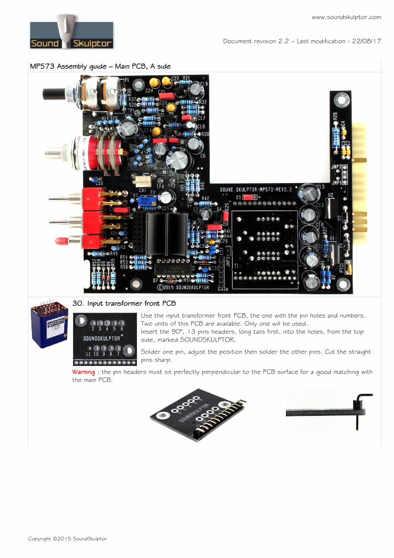
31. Input transformer back PCB
Use the input transformer back PCB. Insert the 90°, 13 pins headers, long tails first, into the holes, from the side marked NOT VISIBLE.Solder one pin, adjust the position then solder the other pins. Only one pin out of two are soldered. Cut the straight pins sharp.
32. Input transformer assembly
Remove the 2 screws from the transformer pin side and insert the front PCB on top of the transformer, checking the pins number correspondence and with the NOT VISIBLE text hidden. Assemble with the 2 screws. Solder the transformer pins.Place the back PCB on the other side of the transformer, with the NOT VISIBLE text hidden. Assemble with the 2 provided screws.
Insert the transformer into the main PCB and solder the pins.Warning: The pins do not protrude much over the PCB so make sure that you heat generously and see the solder flow into the holes.
33. Output transformer PCB
Place the 2x8 pins, 90° connector on the output transformer PCB, on the side where it is drawn. Solder.
Cut the output transformer wires at approximately 14 cm (5.5”). Strip out 5mm. Insert, one at a time, the wires from the PCB side with the colour identifiers, taking care of matching the wire colour with the ID. Insert the stripped end into the corresponding hole and solder.
For a cleaner aspect, respect the wire parallelism from transformer to PCB.YE=yellow, BK=black, OR=orange, BL=blue, GR=green, RD=red, VI=violet, BR=brown.
34. Jumpers
Place one jumper on CN1 at the position marked by a white line.Place one jumper on JMP3. This jumper will be removed after testing.
35. Visual check
At this point, brush the solder side with a hard tooth brush to remove any remaining solder bits.
Make a full visual check. Any missing component on the board ? Any remaining component in the box ?
When everything looks correct, proceed with the frame assembly.
Copyright ©2015 SoundSkulptor

www.soundskulptor.com
Document revision 2.2 – Last modification : 22/08/17
MP573 Assembly guide – Main PCB, A side
36. Output transformer assembly
Insert 4 M3x35mm countersunk screws into the side plate. On each screw, insert one 4mm spacer. Insert the transformer on the 4 screws and attach with 4 self locking nuts. Tighten without crushing the transformer frame.
37. PCB & front plate assembly
Place the PCB on the side plate and attach with four 25mm spacers and 4 lock washers. Do not tighten yet, letting the PCB free to play within the holes size.
Remove the nut on the Grayhill rotary switch but leave the lock washer in place.
Assemble the front plate, watching the LED position and attach to the side plate with 2 M3x6mm countersunk black screws.
Place the nut on the Grayhill and tighten gently.
Tighten the 4 spacers on the PCB.
Warning : Do not confuse the M3x6mm countersunk black screws with the #4-40 3/8" black screw that are used to attach the module in the lunchbox.
38. Output transformer connection
Twist the output transformer wires several times and plug the connector into the main PCB, matching the white dot positions on the two PCB's.
Copyright ©2015 SoundSkulptor

www.soundskulptor.com
Document revision 2.2 – Last modification : 22/08/17
MP573 Assembly guide – Main PCB, A side
39. Knobs
Attach the 2 knobs, using the included 1.5mm hex key.
MP573 Assembly guide – DI board
40. Horizontal resistors
Add R59 to R61, R63 to R69.Control the resistor values with a digital multimeter. Bend the leads at 0.4” with a lead forming tool.
41. Vertical resistor
Add R62. This resistor is placed vertically. Bend one leg 180° sharp and insert.
42. Diodes
Add D11 and D12. These diodes are placed vertically. Bend the cathode leg (identified by the black ring).Warning : Make sure to respect the direction of the diodes which is marked by a ring on the component and a 'K' on the PCB marking.
43. Film capacitor
Add C34.
44. Transistors
Add Q7 and Q8.The PCB has provision for two pinouts for Q8. With the current 2SK170, use the A position.
Warning : Watch out the transistor direction.
45. Electrolytic capacitors
Add C35, C36, C37.Solder one lead first, adjust verticality then solder the second lead.Warning : The +lead must go into the +hole. Do not reverse!
Copyright ©2015 SoundSkulptor
www.soundskulptor.com
Document revision 2.2 – Last modification : 22/08/17
MP573 Assembly guide – DI board
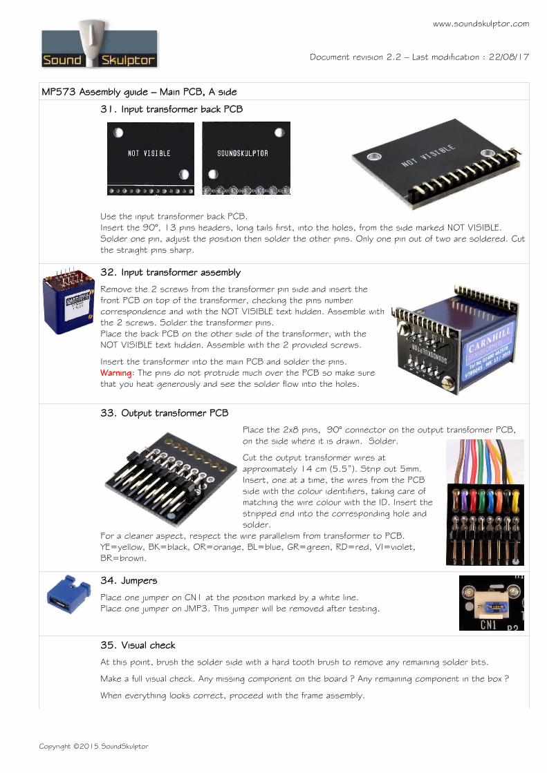
46. Jack connector
Add CN4. The position of the socket is important for a good front-plate matching. It must sit flaton the PCB. Press firmly the socket on the PCB and solder one of the pins. Check position then solderthe other pins.
47. 6 pins Connector
Solder the connector CN3b. Solder one pin first, check verticality, then solder the other pins.Warning : the connector pins must be exactly perpendicular to the PCB to allow proper insertion into the preamp board.
48. Visual check
Brush the solder side with a hard tooth brush to remove any remaining solder bits. Make a full visual check. Any missing component on the board ? Any remaining component in the box ?
MP573 Assembly guide – Final assembly
49. Setup
Your MP573 is now ready for test and setup. Please follow instructions in the “MP573 Setup” document.
50. DI board installation
Place one 1.2mm black plastic spacer on the jack socket and insert into the front panel while fitting the CN3 connector pins into the socket on the main PCB. Screw in the front nut through the bevelled front spacer with an M12 socket spanner.
51. Closing
Attach the cover PCB with four M3x6 countersunk screws.
Copyright ©2015 SoundSkulptor

www.soundskulptor.com
Document revision 2.2 – Last modification : 22/08/17
MP573 Assembly guide – Final assembly
MP573 Assembly guide – Link cable assembly (for connecting to EQ573)
1. Connector soldering
Insert the 3 pins female connector into the second row of holes (circled red). You can add a drop of instant glue between connector and PCB to improve reliability. And solder. Repeat for the second PCB.
2. Cable striping
Split the 2 sections of the wire on a length of 3cm.Strip 2cm of each section.Merge the shield wires from the 2 sections and twist, red in the middle.Strip red and yellow wires on 4mm.Tin the wire tips to keep them together, with very little solder or they won't fit into the PCB holes.
Copyright ©2015 SoundSkulptor

www.soundskulptor.com
Document revision 2.2 – Last modification : 22/08/17
MP573 Assembly guide – Link cable assembly (for connecting to EQ573)
3. Cable soldering
Insert the cable 3 wires from beneath the PCB into the 3 unplated holes, red in centre, yellow on the “Y” side. Insert the red and yellow wire tips into the corresponding PCB holes and solder.
Cut the shield cable to the good length, flatten it on the rectangular pad and solder.
Repeat for the other side of the cable.
Copyright ©2015 SoundSkulptor
![First Revision No. 49-NFPA 17A-2015 [ Detail ]€¦ · First Revision No. 12-NFPA 17A-2015 [ Section No. 2.2 ] 2.2 NFPA Publications. National Fire Protection Association, 1 Batterymarch](https://static.fdocuments.net/doc/165x107/5f81326cfdb6e6131b21892d/first-revision-no-49-nfpa-17a-2015-detail-first-revision-no-12-nfpa-17a-2015.jpg)


![Second Revision No. 11-NFPA 30-2013 [ Section No. 2.2 ]€¦ · · 2013-08-14Second Revision No. 11-NFPA 30-2013 [ Section No. 2.2 ] ... NFPA 96, Standard for Ventilation Control](https://static.fdocuments.net/doc/165x107/5b053b107f8b9abf568b62fc/second-revision-no-11-nfpa-30-2013-section-no-22-2013-08-14second-revision.jpg)


![First Revision No. 339-NFPA 72-2013 [ Section No. 2.2 ] Revision No. 339-NFPA 72-2013 [ Section No. 2.2 ] ... National Fire Protection Association, 1 Batterymarch Park, Quincy, MA](https://static.fdocuments.net/doc/165x107/5af4a3ef7f8b9a74448d1f27/first-revision-no-339-nfpa-72-2013-section-no-22-revision-no-339-nfpa-72-2013.jpg)
![First Revision No. 20-NFPA 56-2015 [ Section No. 1.1.2 ]...First Revision No. 5-NFPA 56-2015 [ Section No. 2.2 ] 2.2 NFPA Publications. National Fire Protection Association, 1 Batterymarch](https://static.fdocuments.net/doc/165x107/61279d16205e26649553b2aa/first-revision-no-20-nfpa-56-2015-section-no-112-first-revision-no.jpg)


![First Revision No. 1-NFPA 96-2015 [ Section No. 2.2 ] · 2016-03-18 · First Revision No. 1-NFPA 96-2015 [ Section No. 2.2 ] ... NFPA 5000®, Building Construction and Safety Code®,](https://static.fdocuments.net/doc/165x107/5b5924617f8b9a657c8cd885/first-revision-no-1-nfpa-96-2015-section-no-22-2016-03-18-first-revision.jpg)