Document on Different Power Plants In Pakistan
35
this page is intentionally left blank
-
Upload
malik-zaid -
Category
Documents
-
view
528 -
download
3
Transcript of Document on Different Power Plants In Pakistan

this page is intentionally left blank

BRIEF CONTENTS
Chapter 1 Introduction
Chapter 2 Brief History Of Electric Power
Chapter 3 Electric Power System
Chapter 4 Generation Of Electric Energy
Chapter 5 Energy Supply And Consumption In Pakistan
Chapter 6 Potential Available For Power Generation
Chapter 7 Power Transmission
Chapter 8 Power Distribution
Chapter 9 Three Phase Power System
Chapter 10 Star – Delta Connections
Chapter 11 Power Transformer
Chapter 12 Auto Transformer
Chapter 13 132/220 KV Switchyard
Chapter 14 Earthing
Chapter 15 Protection Relays & Protection System Of Hydel Power Plant
Chapter 16 Turbines & Generators
Chapter 17 50/230V D.C Batteries
Chapter 18 Auxiliary And Emergency Supply System
Chapter 19 Fire Protection System

TABLE OF CONTENTS
Chapter 1 Introduction ........................................................................................................................................... 1
1.1 electric charge ........................................................................................................................................ 1
1.2 electric field ............................................................................................................................................ 1
1.3 electric potential .................................................................................................................................... 1
1.4 electric current ....................................................................................................................................... 1
1.5 electromagnets ...................................................................................................................................... 1
1.6 electric power ........................................................................................................................................ 1
1.7 electronics .............................................................................................................................................. 1
1.8 Generation ............................................................................................................................................. 2
1.9 Transmission system .............................................................................................................................. 2
1.10 Load ...................................................................................................................................................... 2
Chapter 2 BRIEF HISTORY OF ELECTRIC POWER ............................................................................................ 2
2.1 Early 1880’s ............................................................................................................................................ 2
Chapter 3 ELECTRICAL POWER SYSTEM ........................................................................................................ 3
3.1 STEPS OF TYPICAL POWER SYSTEM ............................................................................................................... 3
Chapter 4 GENEARATION OF ELECTRICAL ENERGY ........................................................................................ 4
4.1 TYPES OF GENERATION STATIONS ................................................................................................................ 4
4.2 GENERATION SOURCES IN PAKISTAN ............................................................................................................ 5
Chapter 5 ENERGY SUPPLY & CONSUMPTION IN PAKISTAN .......................................................................... 5
Chapter 6 POTENTIAL AVAILABLE FOR POWER GENERATION ........................................................................ 6
6.1 MULTIPURPOSE PROJECT .............................................................................................................................. 6
6.2 HYDEL POTENTIAL ......................................................................................................................................... 6
6.2.1 Run of River Projects Feasibility Studies in Hand ................................................................................... 6

6.2.2 PAKISTAN’S TOTAL HYDROPOWER POTENTIAL ..................................................................................... 7
6.3 COAL POTENTIAL ........................................................................................................................................... 7
6.3.1 COAL RESOURCES OF PAKISTAN: ............................................................................................................ 8
6.3.2 COAL RESOURCES IN SINDH ................................................................................................................... 8
6.3.3 COAL RESOURCES IN BALOCHISTAN ....................................................................................................... 9
6.3.4 COAL RESOURCES IN PUNJAB ................................................................................................................. 9
6.3.5 COAL RESOURCES IN KPK ........................................................................................................................ 9
6.3.6 COAL RESOURCES IN AJK ...................................................................................................................... 10
6.3.7 FUTURE COAL BASED POWER PROJECTS .............................................................................................. 10
Chapter 7 POWER TRANSMISSION ............................................................................................................. 11
Chapter 8 POWER DISTRIBUTION ............................................................................................................... 12
8.1 FEEDERS ....................................................................................................................................................... 13
8.2 DISTRIBUTORS ............................................................................................................................................. 13
8.3 SERVICE ........................................................................................................................................................ 13
8.4 UTILITY ......................................................................................................................................................... 14
Chapter 9 THREE PHASE POWER SYSTEM ................................................................................................... 14
9.1 THREE-PHASE SUPPLY ................................................................................................................................. 15
9.2 BALANCED 3-PHASE SYSTEM ....................................................................................................................... 16
9.3 ADVANTAGES OF 3-PHASE POWER SYSTEM ............................................................................................... 16
9.4 THREE PHASE TRANSMISSION LINES ........................................................................................................... 16
Chapter 10 STAR-DELTA CONNECTIONS ..................................................................................................... 17
Chapter 11 POWER TRANSFORMER ........................................................................................................... 18
11.1 TRANSFORMERS ........................................................................................................................................ 18
11.1.1 INDUCTION ......................................................................................................................................... 18
11.2 POWER TRANSFORMERS ........................................................................................................................... 19
Chapter 12 AUTO TRANSFORMER .............................................................................................................. 20
12.1 CUIRCUIT DIAGRAM OF AUTO TRANSFORMER ........................................................................................ 20
12.2 As a result .................................................................................................................................................. 20
12.3 USE OF AUTO TRANSFORMER ................................................................................................................... 21
Chapter 13 132/220 KV SWITCHYARD ........................................................................................................ 21
Chapter 14 EARTHING ................................................................................................................................ 22
14.1 CONCEPT OF EARTHING SYSTEM .............................................................................................................. 22

14.2WHAT IS EARTHING .................................................................................................................................... 22
14.3 GOOD EARTHING MEANS: ......................................................................................................................... 23
14.4 QUALITIES .................................................................................................................................................. 23
14.5 PURPOSE.................................................................................................................................................... 23
Chapter 15 PROTECTION RELAYS & PROTECTION SYSTEM OF HYDEL POWER PLANT ................................... 23
Chapter 16 AUXILIARY AND EMERGENCY SUPPLY SYSTEM .......................................................................... 25
16.1 GENERAL REQUIREMENTS ........................................................................................................................ 25
Chapter 17 FIRE PROTECTION SYSTEM ....................................................................................................... 26
17.1 FIRE PROTECTION SYSTEM ........................................................................................................................ 26
17.2 OVER SPEED PROTECTION SYSTEM ........................................................................................................... 26
17.3 OVER TEMPERATURE PROTECTION SYSTEM............................................................................................. 26
-------------------------------------------------------------------------------------------------------

LIST OF FIGURES
Figure 1. Components of a Power System ................................................................................. 2
Figure 2. Typical Power System. ............................................................................................ 3
Figure 3. Typical Power Distribution System ............................................................................ 13
Figure 4. Elements of a Distribution System .......................................................................... 14
Figure 5. Three-phase supply .................................................................................................. 15
Figure 6. Three Phase Transmission Lines ................................................................................ 17
Figure 7. (a) Mesh connected network ............................................................................. 17
(b) Delta-connected network. .............................................................................. 17
Figure 8. (a) T-connected network. .................................................................................... 17
(b) Star-connected network. ................................................................................ 18
Figure 9. induction law in Transformer .................................................................................... 19
Figure 10. An example of a power transformer used in electric power system........................ 20
Figure 11. Auto vs Isolation Transformer ................................................................................. 20
Figure 12. Concept of Earthing ................................................................................................ 22
Figure 13. Typical single –line ac connection of a protective relay with its de trip schematic .. 25

LIST OF TABLES
Table 1 - Primary Energy Mix by Country 2003-04 .................................................................. 5
Table: 2 – Energy Supply in Pakistan 2003-04 ............................................................................ 5
Table 3 – Energy Consumption in Pakistan 2003-04 .................................................................. 5
Table 4 – Future Multipurpose projects in Pakistan 2003-04 ..................................................... 6
Table 5 - Hydel Projects under Feasibilty in Pakistan 2003-04 ................................................... 7
Table 6 – Total Hydro Power Potential in Pakistan 2003-04 ....................................................... 7
Table 7 – Coal Resources in Sindh 2003-04 ................................................................................ 8
Table 8 – Coal Resources in Balochistan 2003-04 ...................................................................... 9
Table 9 – Coal Resources in Punjab 2003-04 .............................................................................. 9
Table 10 – Coal Resources in KPK 2003-04 ............................................................................... 9
Table 11 – Coal Resources in AJK 2003-04 ............................................................................... 10
Table 12 – Future Coal Based Power Projects 2003-04 ............................................................ 10


1
Introduction
Electricity is the set of physical phenomena associated with the presence and flow of electric charge. Electricity gives a wide variety of well-known effects, such as lightning, static electricity, electromagnetic induction and electric current. In addition, electricity permits the creation and reception of electromagnetic radiation such as radio waves.
In electricity, charges produce electromagnetic fields which act on other charges. Electricity occurs due to several types of physics:
electric charge: a property of some subatomic particles, which determines their electromagnetic interactions. Electrically charged matter is influenced by, and produces, electromagnetic fields.
electric field (see electrostatics): an especially simple type of electromagnetic field produced by an electric charge even when it is not moving (i.e., there is no electric current). The electric field produces a force on other charges in its vicinity.
electric potential: the capacity of an electric field to do work on an electric charge, typically measured in volts.
electric current: a movement or flow of electrically charged particles, typically measured in amperes.
electromagnets: Moving charges produce a magnetic field. Electric currents generate magnetic fields, and changing magnetic fields generate electric currents.
In electrical engineering, electricity is used for:
electric power where electric current is used to energise equipment;
electronics which deals with electrical circuits that involve active electrical
components such as vacuum tubes, transistors,diodes and integrated circuits, and associated passive interconnection technologies.
Electricity is the basic need for the economic development of any country. Electricity has
now become a necessity for all as it powers the machinery, the computers, the health-care
systems and the entertainment of modern society. Every power system has three major
components.which are as follows:

2
LoadT.L
Transmission Line
Generator
Distribution
Figure 1 Components of a Power System
Generation: source of power, ideally with a specified voltage and Frequency.
Transmission system: transmits power; ideally as a perfect conductor.
Load: consumes power; ideally with a constant resistive value.
BRIEF HISTORY OF ELECTRIC POWER Early 1880’s – Edison introduced Pearl Street dc system in Manhattan supplying 59
customers
1884 – Sprague produces practical dc motor
1885 – invention of transformer
Mid 1880’s – Westinghouse/Tesla introduce ac system
Late 1880’s – Tesla invents ac induction motor
1893 – First 3 phase transmission line operating at 2.3 kV
1896 – ac lines deliver electricity from hydro generation at Niagara Falls to Buffalo, 20
miles away
Early 1900’s – Private utilities supply all customers in area (city); recognized as a natural
monopoly; states step in to begin regulation
By 1920’s – Large interstate holding companies control most electricity systems
1935 – Congress passes Public Utility Holding Company Act to establish national
regulation, breaking up large interstate utilities

3
1935/6 – Rural Electrification Act brought electricity to rural areas
ELECTRICAL POWER SYSTEM How electrical power system works in various places is defined in the figure given
below:
Figure 2 Typical Power System.
STEPS OF TYPICAL POWER SYSTEM:
1) The generating station converts the energy of gas, oil, coal or nuclear fuel to electric
energy. The generator voltage is around 15-25 kV (12.5KV at Mangla Dam Generation).
2) The main transformer increases the voltage to 230-765 kV. (220-500KV in Pakistan). This
reduces the current and losses.
3) The high voltage transmission line transports the energy from the generating station to
the large loads, like towns. Example: Energy generated at Palo Verde is transported by a
500 kV line to the KYRENE substation at Phoenix.
4) The high voltage substation reduces the voltage to 500-220 / (220-132) kV. The substation
serves as a node point for several lines.

4
5) The sub-transmission lines (132 kV-11 kV) connect the high voltage substation to the local
distribution station.
6) The Distribution lines 11 kV distribute the energy along streets or underground. Each line
supplies several step-down transformers distributed along the line.
7) The distribution transformer reduces the voltage to 240 (1-phase) or 415V (3-phase)
which supplies the houses, shopping centers, etc.
GENEARATION OF ELECTRICAL ENERGY Electrical energy is generated at the power stations by synchronous generators. Typical
generation voltages vary from 3.3 to 33 kV depending upon the demand of the load.
TYPES OF GENERATION STATIONS:
1. Thermal Power Plant
Large plants (more than 500 MVA) carry constant load (base load plant).
Smaller plants loads are regulated but they operate continuously. Minimum down
time is 20-35 hours. Depending upon the situation of the fossil fuel availability, it
can be used as base load or peak load plant. But in Pakistan, it is used as peak load
plant.
2. Nuclear Power Plant
These plants carry constant load and are used as base loads plants.
3. Hydroelectric Plants
These plants are loaded to the maximum capacity, because of the low
operating cost. (Water is free)
4. Combined Steam and Gas-Turbine Power Plants
High efficiency plants for variable load.
5. Gas Turbine Power Plants
Peak load plants, high operating and low investment cost.
6. Renewable Energy Sources (Solar & Wind) Power Plants
Loaded to the maximum capacity when sun or wind power available.

5
GENERATION SOURCES IN PAKISTAN:
The Energy mix in Pakistan and various other countries for the year 2003-04 is given
in Table 1.1:
Sources Pakistan India UK USA Canada
Oil 30.0% 35.0% 35.0% 40.0% 30.0%
Natural Gas 50.0 % 7.0% 35.0% 23.0% 27.0%
Coal 1.0 % 55.0% 16.0% 23.0% 24.0%
Other (Hydel, Nuclear, etc.) 19% 3.0% 14.0% 14.0% 19.0%
Table 1 - Primary Energy Mix by Country 2003-04
ENERGY SUPPLY & CONSUMPTION IN PAKISTAN Source wise primary energy supply in Pakistan in 2003-04 is indicated below:
Gas Hydel Coal Nuclear
15.8 % 50.8 % 30 % 0.2 % Oil
Table: 2 – Energy Supply in Pakistan 2003-04
Sector wise energy consumption, excluding fuels consumed in thermal power generation in the
Year 2004 is as follow:
Industry Transport Domestic Commercial Agriculture Other
Governments
38.3 % 32.0 % 21.7 % 3.2 % 2.5 % 2.3 %
Table 3 – Energy Consumption in Pakistan 2003-04
6
POTENTIAL AVAILABLE FOR POWER GENERATION God has blessed Pakistan with tremendous potentials available for power generation is:
Hydel Potential
Coal Potential
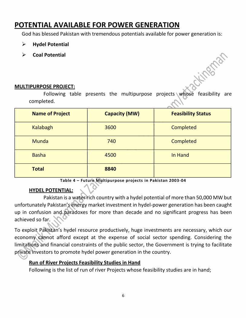
MULTIPURPOSE PROJECT:
Following table presents the multipurpose projects whose feasibility are
completed.
Name of Project Capacity (MW) Feasibility Status
Kalabagh 3600 Completed
Munda 740 Completed
Basha 4500 In Hand
Total 8840
Table 4 – Future Multipurpose projects in Pakistan 2003-04
HYDEL POTENTIAL:
Pakistan is a water rich country with a hydel potential of more than 50,000 MW but
unfortunately Pakistan’s energy market investment in hydel-power generation has been caught
up in confusion and paradoxes for more than decade and no significant progress has been
achieved so far.
To exploit Pakistan’s hydel resource productively, huge investments are necessary, which our
economy cannot afford except at the expense of social sector spending. Considering the
limitations and financial constraints of the public sector, the Government is trying to facilitate
private investors to promote hydel power generation in the country.
Run of River Projects Feasibility Studies in Hand
Following is the list of run of river Projects whose feasibility studies are in hand;

7
Name of Project Capacity (MW) Feasibility Status
Bunji 5400 In Hand “
Dasu 3700 “
Gabral 105 “
Keyel Khwar 130 “
Lawi 65 “
Spat Gah
Lower scheme
545 “
Chor Nullah
Lower scheme
386 “
Total 10331
Table 5 - Hydel Projects under Feasibilty in Pakistan 2003 -04
PAKISTAN’S TOTAL HYDROPOWER POTENTIAL :
Following is the total hydro power potential in Pakistan;
Station/Projects Capacity (MW)
Hydel Stations in Operation 6596
Under Implementations 1965
Feasibility Study Completed
i. Run Of River
ii. Multipurpose
1780
8840
Feasibility Studies in Hand 10331
Projects for Which Feasibility Studies are to be Carried Out 25000
Total 54511
Table 6 – Total Hydro Power Potential in Pakistan 2003 -04
COAL POTENTIAL:
Coal is global energy source in the true sense of the world. Coal contributes
approximately 38% to the total global primary energy demand. Share of coal in total electricity
production in different countries are:
China = 81%
USA = 56 %

8
UK = 58 %
Unfortunately, the share of coal in total electricity production in Pakistan is less than 1%.
Pakistan is a coal rich country, but unfortunately coal has not been developed for power
generation for more than three decades due to lack of infrastructure, insufficient financing and
absence of modern coal mining expertise. The Government has now determined to facilitate
private investors to promote investment in coal development and coal power generation.
Coal is a cheap indigenous resource and after the discovery of 175.5 billion tones of coal in Thar
area of Sind, Pakistan’s coal power potential has increased manifold. It is anticipated that if
properly exploited, Pakistan’s coal resources may generate more than 100,000 MW of electricity
for the next 30 years. Pakistan is now the 6th richest nation of the world in respect of coal
resources.
COAL RESOURCES OF PAKISTAN:
There are vast resources of coal i.e. 185,175 million tonnes in all four of Pakistan’s
provinces and in AJK
COAL RESOURCES IN SINDH:
Following are the coal resource is Sindh area.
Location Million Tonnes
Thar 175,506
Lakhra 1,328
Sondra – Jherruck 5,523
Meting – Jhimpir 473
Indus East 1,777
Badin 16
Total 184,623
Table 7 – Coal Resources in Sindh 2003-04

9
COAL RESOURCES IN BALOCHISTAN:
Following are the coal resources in Balochistan.
Location Million Tonnes
Sor - Range/Degari 50
Khostan/sharigh/Hanai/Ziarat 88
Mach 23
Duki 56
Total 217 Table 8 – Coal Resources in Balochistan 2003-04
COAL RESOURCES IN PUNJAB:
Following are coal resources in Punjab.
Location Million Tonnes
Salt - Range 213
Makarwal 22
Total 235
Table 9 – Coal Resources in Punjab 2003-04
COAL RESOURCES IN KPK:
Following are coal resources in NWFP
Location Million Tonnes
Cherat 9
Hungu 82
Total 91
Table 10 – Coal Resources in KPK 2003-04

10
COAL RESOURCES IN AJK:
Following is coal resource in AJK.
Location Million Tonnes
Kotli 9
Table 11 – Coal Resources in AJK 2003-04
FUTURE COAL BASED POWER PROJECTS:
Following is the list of coal based power project in Pakistan.
Projects Capacity ( MW )
Thar Coal 4200
Lakhra Coal 450
Sonda – Jherruk Coal 200
Ghotki 150
Total 5000
Table 12 – Future Coal Based Power Projects 2003-04
The electricity demand in the country is increasing day by day. The demand/supply
projections indicates that power shortage will appear from the year 2006, and will increase to
5500 MW in the year 2010 if no measures are taken to bring in new capacity.For Pakistan, the
cornerstone of self-reliance in power sector development is optimal utilization of hydel
resources.

11
Hydropower is cheaper, eternally available source of energy and a bounty of nature in contrast
to environmentally hazardous and non-renewable sources of energy. Pakistan is fortunate to be
endowed with economically exploitable hydropower potential of more than 50,000 MW.
There are vast resources of coal in Pakistan as well and coal is a cheap indigenous energy
resource. Pakistan’s coal resources may generate more than 100,000 MW of electricity for the
next 30 years.
The power requirements must be fulfilled by setting up new projects based on indigenous fuel
resources such as coal, hydel power, and renewable energies.
Development & utilization of indigenous available potential fuel resources will not only reduce
the cost of electricity but also strengthen the country’s economy and save precious foreign
exchange.
POWER TRANSMISSION The power stations are located quite far away from the load centers. Transmission
networks are required to:
Connect generating plants to consumption points
Create large power pools for increased reliability
The primary transmission voltages are 110, 132, 220 or 500 kV depending upon the distance and
amount of power to be transmitted. Secondary transmission is normally of the order of 66kV
(obsolete in Pakistan now) and 132 kV.
High voltage AC transmission offers:
Higher transmission capacity / Km
Lower line-voltage drop / Km
Lower transmission losses / MW transfer
Reduced right-of-way requirement / MW transfer
Lower capital and operating costs / MW transfer
The equipment used for power transmission system is
Transformers
Step-up transformer

12
Voltage Regulators
Phase Shifters
Step-down Transformers
Transmission Lines & Cables
Relays & Circuit Breakers
Disconnectors & Earthing Switches
Shunt & Series Reactors & Capacitors
Static VAR Compensators
Current Transformers & Potential Transformers
POWER DISTRIBUTION Power Distribution System receives electrical energy from the HV/MV levels at bulk
power delivery points and supplies energy to customers
At standard voltage levels
Single phase and/or three-phase
The voltages for primary distribution are 11, 6.6 or 3.3 kV depending upon the requirement of
bulk consumers and for secondary distribution the voltage level are 415/240V.
It is made up of the following main equipment:
Distribution transformers (DXF)
Feeder sections (including underground cables)
Switches, fuses, reclosures
Automatic load transfers

13
14
Bulk
Power
Point
33/11
DXF11/5
DXF
5/0.4/0.21
DXF
HV / MV
Network
33KV 15 KV 5 KV220V
Industrial
Customers
Residential
Customers
Commercia
l
& Municipal
Customers
Large
Industrial
Customers
Power Distribution
Figure 3. Typical Power Distribution System
A distribution system may further be classified into feeders, distributors and service mains.
1. FEEDERS:
Feeders are the conductors, which connect the substations to the areas fed
by those substations. Generally feeders are not tapped at any point for supply to
the consumers, therefore, current density remains constant throughout the length
of the feeder. Hence, it is designed mainly for constant current carrying density.
2. DISTRIBUTORS:
Distributors are the conductors from which load is tapped at different points
for supply to the consumers. The current density of a distributor does not remains
constant throughout its length. Distributors are designed mainly for voltage drop
in them. The voltage drop in a distributor should not exceed +- 5%.
3. SERVICE MAINS:
Service Mains are the conductors, which connect the distributor to the
consumer’s premises.

14
Figure 4. Elements of a Distribution System
UTILITY RESTRUCTURING :
Driven by significant regional variations in electric rates
Goal of competition is to reduce rates through the introduction
of competition
Eventual goal is to allow consumers to choose their electricity
supplier
In Pakistan, WAPDA is also under the process of disintegration. Eight Distribution
companies (Disco) are being constituted: which are
LESCO
GEPCO
MEPCO
IESCO
FESCO
KESC
PESCO
THREE PHASE POWER SYSTEM:

15
THREE-PHASE SUPPLY:
A three-phase supply is generated when three coils are placed 120° apart and the
whole rotated in a uniform magnetic field as shown in Figure 19.2(a). The result is three
independent supplies of equal voltages which are each displaced by 120° from each other as
shown in Figure 19.2(b).
The convention adopted to identify each of the phase voltages is:
R-red, Y-yellow, and B-blue, as shown in Figure 19.2.
Figure 5. Three-phase supply
The phase-sequence is given by the sequence in which the conductors pass the point
initially taken by the red conductor. The national standard phase sequence is R, Y, B.
A three-phase a.c. supply is carried by three conductors, called ‘lines’ which are coloured red,
yellow and blue. The currents in these conductors are known as line currents (IL) and the
p.d.’s between them are known as line voltages (VL). A fourth conductor, called the neutral
(coloured black, and connected through protective devices to earth) is often used with a
three-phase supply.
If the three-phase windings shown in Figure 19.2 are kept independent then six wires are
needed to connect a supply source (such as a generator) to a load (such as motor). To reduce
the number of wires it is usual to interconnect the three phases. There are two ways in which
this can be done, these being:
A Astar connection, and
A delta, or mesh, connection.
Sources of three-phase supplies, i.e. alternators, are usually connected in star,

16
whereas three-phase transformer windings, motors and other loads may be connected
either in star or delta.
BALANCED 3-PHASE SYSTEM:
A balanced 3 phase () system has
three voltage sources with equal magnitude, but with an angle shift of 120
equal loads on each phase
equal impedance on the lines connecting the generators to the loads
Bulk power systems are almost exclusively 3
Single phase is used primarily only in low voltage, low power settings, such as residential and
some commercial
ADVANTAGES OF 3-PHASE POWER SYSTEM:
Can transmit more power for same amount of wire (twice as much as single phase)
Torque produced by 3 machines is constant
Three phase machines use less material for same power rating
Three phase machines start more easily than single phase machines
THREE PHASE TRANSMISSION LINES:

17
Figure 6. Three Phase Transmission Lines
STAR-DELTA CONNECTIONS:
The network shown in Figure (a) consisting of three mpedances ZA, ZB and ZC is said to be
p-connected. This network can be redrawn as shown in Figure (b), where the arrangement is
referred to as deltaconnected or mesh-connected.
Figure 7. (a) Mesh connected network,
(b) Delta-connected network.
The network shown in Figure 34.2(a), consisting of three impedances, Z1, Z2 and Z3, is said to be
T-connected. This network can be redrawn as shown in Figure 34.2(b), where the arrangement
is referred to as starconnected.
Figure 8 (a) T-connected network.

18
(b) Star-connected network.
POWER TRANSFORMER TRANSFORMERS:
A transformer is a static electrical device used in electric power systems to transfer
power between circuits through the use of electromagnetic induction. Transformers are devices
that transfer energy from one circuit to another by means of a common magnetic field. When
an alternating current flows in a conductor, a magnetic field exists around the conductor. If
another conductor is placed in the field created by the first conductor such that the flux lines
link the second conductor, then a voltage is induced into the second conductor. The use of a
magnetic field from one coil to induce a voltage into a second coil is the principle on which
transformer theory and application is based. Transformers range in size from thumbnail-sized
used in microphones to units weighing hundreds of tons interconnecting the power grid. A wide
range of transformer designs are used in electronic and electric power applications.
Transformers are essential for the transmission, distribution and utilization of electrical energy.
INDUCTION LAW:
The transformer is based on two principles:
An electric current can produce a magnetic field.
A changing magnetic field within a coil of wire induces a voltage across the ends of
the coil (electromagnetic induction).

19
Figure 9. induction law in Transformer
Referring to the figure here, current passing through the primary coil creates a magnetic field.
The primary and secondary coils are wrapped around a core of very high magnetic permeability,
so that most of the magnetic flux passes through both the primary and secondary coils. Any
secondary winding connected load causes current
and voltage induction from primary to secondary circuits in indicated directions. POWER TRANSFORMERS
The term power transformer is used to refer to those transformers used in the generator and the distribution circuits, and these are usually rated at 500 KVA and above. Power systems typically consist of a large number of generation locations, distribution points, and interconnections within the system or with nearby systems, such as a neighboring utility. The complexity of the system leads to a variety of transmission and distribution voltages. Power transformers must be used at each of these points where there is a transition between voltage levels.

20
Figure 10. An example of a power transformer used in electric power system
AUTO TRANSFORMER Transformer that acts like an isolation transformer by changing
Voltage Levels
Current Levels
Impedance values
But does not isolate between the Primary and the Secondary
CUIRCUIT DIAGRAM OF AUTO TRANSFORMER:
Circuit diagram of auto transformer is as follow:
Figure 11. Auto vs Isolation Transformer
As a result:

21
Requires less copper
Lighter
I2R losses are less
More efficient
Lower leakage
Lower losses
Lower magnetizing current
Increase kVA rating
No galvanic Isolation
USE OF AUTO TRANSFORMER:
In power distribution lines to counteract line Z
Motor starting circuits
If there is an insulation breakdown between coils the supply voltage may be
imposed onto the low voltage load
It is recommended that the voltage reduction should only be by a maximum of
25%
132/220 KV SWITCHYARD Switchyard is basically switching scheme which may be termed as substation for
transmission while Planning and design of substations to be based on the following aspects:
Security of supply, extendibilty, maintainabilty and operational flexibility
Statutory safety requirements
Protection from direct lightening stroke
Switching scheme:-
765 kV Substation: Double bus double breaker
400 kV Substation: One and half breaker scheme/ double main and transfer bus bar
scheme
220 kV Substation: Double main and transfer scheme/ double main with breaker
by-pass scheme

22
132kV Substation: Main and transfer scheme.
EARTHING:
CONCEPT OF EARTHING SYSTEM:
All the people living or working in residential, commercial and industrial
installations, particularly the operators and personnel who are in close operation and contact
with electrical systems and machineries, should essentially be protected against possible
electrification. To achieve this protection, earthing system of an installation is defined,designed
and installed according to the standard requirements.
WHAT IS EARTHING:
The process of connecting metallic bodies of all the electrical apparatus and
equipment to huge mass of earth by a wire having negligible resistance is called Earthing. The
term earthing means connecting the neutral point of supply system or the non current carrying
parts of the electrical apparatus to the general mass of earth in such a manner that all times an
immediate discharge of electrical energy takes place without danger.
Figure 12. Concept of Earthing
1 OBJECTIVES OF THE EARTHING:
Provide an alternative path for the fault current to flow so that it will not
endanger the user

23
Ensure that all exposed conductive parts do not reach a dangerous potential
Maintain the voltage at any part of an electrical system at a known value so as
to prevent over current or excessive voltage on the appliances or equipment.
GOOD EARTHING MEANS:
Good Earthing must have low impedance enough to ensure that sufficient
current can flow through the safety device so that it disconnects the supply ( <0.4
sec ). Fault current is much more than the full load current of the circuit which melts
the fuse. Hence, the appliance is disconnected automatically from the supply
mains.
1 QUALITIES OF GOOD EARTHING:
Must be of low electrical resistance
Must be of good corrosion resistance
Must be able to dissipate high fault current repeatedly
1 PURPOSE OF EARTHING:
To save human life from danger of electrical shock or death by blowing a fuse
i.e. To provide an alternative path for the fault current to flow so that it will not
endanger the user
To protect buildings, machinery & appliances under fault conditions ie. To
ensure that all exposed conductive parts do not reach a dangerous potential.
To provide safe path to dissipate lightning and short circuit currents.
To provide stable platform for operation of sensitive electronic
equipments i.e. To maintain the voltage at any part of an electrical system at a
known value so as to prevent over current or excessive voltage on the
appliances or equipment .
To provide protection against static electricity from friction
PROTECTION RELAYS & PROTECTION SYSTEM OF HYDEL POWER
PLANT 1 WHAT IS A RELAY?
(IEEE) define a relay as an electric device that is designed to interpret input
condition in a prescribed manner and after specified condition are met to respond to cause

24
contact operation .Relay are utilized in all as pacts of activity, the home ,communication ,
industry…..etc.
A protective relay is defined as a relay whose function is to detect defective line or apparatus or
other power system condition of an abnormal or dangerous nature and to initiate appropriate
control circuit condition. Fuse are also used in protection and define as an over current
protective device with in a circuit opening fusible part that is heated and severed by the passage
of the over current thought it.
A primary objective of all power system is to maintain a very high level of condition of service,
and to minimize the outage times when intolerable conditions occur. Loss of power, dip of
voltage and over voltage will occur due to consequences of natural events, physical accident,
equipment failure a disoperation by human error.
Protection is the science, skill, and art of applying and setting and / or fuses to provide
maximum sensitivity to fault and undesirable condition.
1 TYPICAL POWER CIRCUIT BREAKER:
Protective relays provide the "brains" to same trouble ,but as low energy device
they are able to open and isolate the problem area of the power system . CBs and varions types
of circuit interrupters are used to provide the "muscle" for fault isolation .
Thus protective relays and interrupting devices are "team" . protective relays without CBs have
no basic value except for alarm. On the other hand , CBs without protective relays are only
energized or de energized manually.
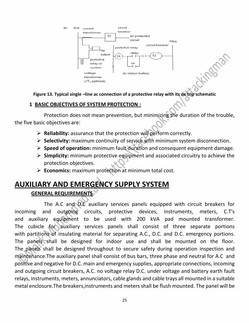
1 TYPICAL RELAY & CB CONNECTION :
Usually protective relays are connected to power system through CT and/or VT.
The circuit can be represented by a typical "one-line'" ac schematic and dc trip circuit schematic
as shown in fig (1-9) . in normal operation and when CB(52) is closed , it is contact closes to
energize the CB trip coil 52T, which function to open breaker main contact and de energize the
connected circuit. The relay contacts are not designed to interrupt the CB trip coil current so an
auxiliary relay is used to "seal in" or by pass the protective relay. Then 52a will open to de
energize the breaker coil.
25
Figure 13. Typical single –line ac connection of a protective relay with its de trip schematic
1 BASIC OBJECTIVES OF SYSTEM PROTECTION :
Protection does not mean prevention, but minimizing the duration of the trouble,
the five basic objectives are:
Reliability: assurance that the protection will perform correctly.
Selectivity: maximum continuity of service with minimum system disconnection.
Speed of operation: minimum fault duration and consequent equipment damage.
Simplicity: minimum protective equipment and associated circuitry to achieve the
protection objectives.
Economics: maximum protection at minimum total cost.
AUXILIARY AND EMERGENCY SUPPLY SYSTEM GENERAL REQUIREMENTS
The A.C and D.C auxiliary services panels equipped with circuit breakers for
incoming and outgoing circuits, protective devices, instruments, meters, C.T's
and auxiliary equipment to be used with 200 kVA pad mounted transformer.
The cubicle for auxiliary services panels shall consist of three separate portions
with partitions of insulating material for separating A.C., D.C. and D.C. emergency portions.
The panels shall be designed for indoor use and shall be mounted on the floor.
The panels shall be designed throughout to secure safety during operation inspection and
maintenance.The auxiliary panel shall consist of bus bars, three phase and neutral for A.C and
positive and negative for D.C. main and emergency supplies, appropriate connections, incoming
and outgoing circuit breakers, A.C. no voltage relay D.C. under voltage and battery earth fault
relays, instruments, meters, annunciators, cable glands and cable trays all mounted in a suitable
metal enclosure.The breakers,instruments and meters shall be flush mounted. The panel will be

26
fed through LT underground cables which will be connected directly to the A.C. and D.C.
incoming circuit breakers terminations.
FIRE PROTECTION SYSTEM FIRE PROTECTION SYSTEM
The CO2 fire protection system for the gas turbine unites extinguishing the fire by
reducing the oxygen.
To reduce the oxygen content, a quantity of Co2 greater than 34% a compared by
volume is discharged in to the combustion chamber, when exposed to high
temperature.
OVER SPEED PROTECTION SYSTEM
Under normal operation the speed of the shaft is under the control of speed loop
or temperature loop.
The over speed protection system consists of a primary electronic system.
The primary electronic over speed protection system senses the turbine speed,
speed detection software and associated circuits.
Mechanical over speed protection system is a backup for electronic over speed
protection system failure.
OVER TEMPERATURE PROTECTION SYSTEM
The over temperature protection system protects the GT from possible damage
caused by over firing. It is a backup system which operates only after failure of the
speed and temperature over ride loops.
Control of turbine is done mainly by start up speed acceleration, synchronization
and temperature controls
Temperature, speed, vibration, flame and compressor operation limits over
temperature and over speed systems are provided as independent backup system
for temperature control and speed control systems.
Vibration detections and protection is activated by abnormal turning vibration
amplitude.
Flame Diction and protection system is activated if flame is not established during
start up or if it is lost during operation.

27
-----------------------------------------------------------------------------------------------------------------------