Document 3 018 281B-NP, EPRI TR-106439 Critical … · 2013-01-11 · in Section 4 documents a...
144
4 NON-PROPRIETARY ARolls-Royce D6slgnation du document Document name Affalre Product Equipement [] Eýquipment EPRI TR-106439 Critical Characteristics and EPRI TR-107330 Compliance Matrix Assessment Report SPINLINE 3 NRC Qualification SPINLINE 3 Digital Safety I&C Platform Sous-ensemble Subassembly Class6 IE ou 6quiv. Safety classification 0 Document contractuel (pour IS client) Contractual document (for custormer oui F non E] yes no Nbre de pages 144 Number of pages Code projet Project code Diffusion interne: Internal distnibution Diffusion externe: External distnbution Nyl1/ Level1 Niv2 / Lewe/2- E.RE-1. 117 ICC, QUA, KLI, MKT, LOG INRC1 Tampon archivage I/ Archive stamp Version francaise R6dIg6 par V6rifl6 par Approuv6 par Witten by Checked by Approved by Nom: Nom: Nom: Name Name Name Visa: Visa: visa: iature Signature Signature -'naura " ia:. Signa. Date •Date Date English version R6dIg6 ou tradult par V6rffi6 par Approuvh par Written or translated by Checked by Approved by Nom : M. Burzynskl Nom : H. Jegou Nom : M. P. Durand Visea.e : Via:e Visa:•! Name Name Name V is a ýht4)I _ , ' • . . . J Vi s a :V is a :1 - Signature'~'YJ Signature Signal Date: Date : Date. I Z) Q f Date /7 A4 ' m•_-o,..,/- Date Date Th. d-Monn collins iffmniotno vwtih i. proyoloony Ond colidendf 10 Rolls-Royo.Civil Nudea, SAS nhich n.~y nok WllýA~ On prior owcifter -oot of Rolls-Royo. Civi Nodeo, SAS, b* wod orprod-Wo, i . hleOlin poll, or nononoicatbdto soy person not emplolyed by Rolln-Royce Civi Noudon &AS, e Roll-Royce plc 2009 Le doocueld Oolttiert don intotmalinOO oottfid~~tielle ot propoiodil do Rol!-Royc. Civi Nuclesir SAS ot no pool noo fs-ord 6otS prdadatde do Roto-Royce CMd Nod..o, SAS, a". uUtUd on repldtntwil, o btolil no wo parde,on COOt C om-minbp 6 m ln. 0 Roll-ROYCa ple 2009 Impriom n' 8303090 F 3 018 281B-NP Page 1
Transcript of Document 3 018 281B-NP, EPRI TR-106439 Critical … · 2013-01-11 · in Section 4 documents a...

4
NON-PROPRIETARY
ARolls-RoyceD6slgnation du documentDocument name
AffalreProduct
Equipement []Eýquipment
EPRI TR-106439 Critical Characteristicsand EPRI TR-107330 Compliance Matrix
Assessment Report
SPINLINE 3 NRC Qualification
SPINLINE 3 Digital Safety I&C Platform
Sous-ensembleSubassembly
Class6 IE ou 6quiv.Safety classification
0
Document contractuel (pour IS client)Contractual document (for custormer
oui F non E]yes no
Nbre de pages 144Number of pages
Code projetProject code
Diffusion interne:Internal distnibution
Diffusion externe:External distnbution
Nyl1/ Level1 Niv2 / Lewe/2-E.RE-1. 117
ICC, QUA, KLI, MKT, LOG
INRC1
Tampon archivage I/ Archive stamp
Version francaise
R6dIg6 par V6rifl6 par Approuv6 parWitten by Checked by Approved by
Nom: Nom: Nom:Name Name NameVisa: Visa: visa:iature Signature Signature
-'naura " ia:. Signa.
Date •Date Date
English version
R6dIg6 ou tradult par V6rffi6 par Approuvh parWritten or translated by Checked by Approved by
Nom : M. Burzynskl Nom : H. Jegou Nom : M. P. DurandVisea.e : Via:e Visa:•!Name Name NameV is a ýht4)I _ , ' • . . . J Vi s a :V is a :1 -Signature'~'YJ Signature SignalDate: Date : Date. I Z) Q fDate /7 A4 ' m•_-o,..,/- Date Date
Th. d-Monn collins iffmniotno vwtih i. proyoloony Ond colidendf 10 Rolls-Royo. Civil Nudea, SAS nhich n.~y nok WllýA~ On prior owcifter -oot of Rolls-Royo. CiviNodeo, SAS, b* wod orprod-Wo, i . hleOlin poll, or nononoicatbd to soy person not emplolyed by Rolln-Royce Civi Noudon &AS, e Roll-Royce plc 2009Le doocueld Oolttiert don intotmalinOO oottfid~~tielle ot propoiodil do Rol!-Royc. Civi Nuclesir SAS ot no pool noo fs-ord 6otS prdadatde do Roto-Royce CMd Nod..o, SAS, a".uUtUd on repldtntwil, o btolil no wo parde, on COOt C om-minbp 6 m ln. 0 Roll-ROYCa ple 2009
Impriom n' 8303090 F 3 018 281B-NPPage 1

NON-PROPRIETARY
jRolls-Royce
TABLEAU DE MISE A JOURRecord of revisions
Indice /dateRedige par Pages modifiles Origine et designation de la modification
Revision letter/date Modified pages Origin and designation of the modificationWritten by
A/ 14.03.2012
M. BURZYNSKI
BI 16.11.2012
M.BURZYNSKI
Edition originale OU First issue
§1.3, §2.1, §4, and §5 Incorporated results of qualification testing
Identification des moyens de production de ce documentIdentification of document production means
Outils Microsoft Office Word Fichier: SPL3_Assessment.Report_3018281B-NP.doc
Tools File
EPRI TR-1 06439 and EPRI TR-1 07330 Compliance Matrix- Assessment ReportImprirne n' 8303090 F
Page 2
3 018 281 B-NP

NON-PROPRIETARY
jRolls-Royce
TABLE DES MATIERESTable of contents
1 INTRODUCTION ......................................................................................................................... 41 .1 P u rp o s e ....................................................................................................................... 41.2 A cronym s and A bbreviations ................................................................................... 41.3 B ackg round ..................................................................................................... . . . . . 61 .4 A p p ro a c h ..................................................................................................................... 8
2 METHODOLOGY AND RESULTS ...................................................... 102.1 M ethod 1 Im plem entation ..................................................................................... 102.2 M ethod 2 Im plem entation .................................................................................... 13
2.2.1 SPINLINE 3 Software Development Process Evaluation ......................... 132.2.2 SPINLINE 3 System Design Evaluation ................................................... 142.2.3 SPINLINE 3 OSS Design Evaluation ........................................................ 152.2.4 SPINLINE 3 Embedded Firmware Evaluation .......................................... 202.2.5 SPINLINE 3 Embedded Software Evaluation .......................................... 21
2.3 M ethod 4 Im plem entation ..................................................................................... 22
3 EPRI TR-1 06439 CRITICAL CHARACTERISTICS FOR ACCEPTANCE .................................... 26
4 EPRI TR-1 07330 REQUIREMENTS AND COMPLIANCE TRACEABILITY MATRIX ...................... 35
5 R EFERENCES ....................................................................................................................... 139
EPRI TR-106439 and EPRI TR-107330 Compliance Matrix- Assessment Reporthmprim, n' 8303090 F
Page 3
3 018 281B-NP

NON-PROPRIETARY
LJ Rolls-Royce
1 INTRODUCTION
1.1 Purpose
This report contains the results of the assessment of the critical characteristics for SPINLINE 3Digital Safety I&C Platform, performed in accordance with EPRI TR-1 06439 (Reference 7).Section 3 shows a "critical characteristics matrix' that lists critical characteristics and providesreferences to acceptance criteria and the verification methods used in verifying them. The matrixcovers each of the three categories of critical characteristics: physical characteristics, performancecharacteristics, and dependability characteristics.
This report also contains the results of the assessment of the SPINLINE 3 Digital Safety I&CPlatform, performed in accordance with EPRI TR-107330 (Reference 6). The assessment resultsin Section 4 documents a detailed compliance matrix demonstrating how the SPINLINE 3 systemcomplies (i.e., Requirement Not Applicable, Fully Complies, Exception Taken, or TR DiscrepancyNoted) with each of the requirements specified in EPRI TR-107330.
This report supplements the information provided in the Rolls-Royce Dedication Report for theGeneric SPINLINE 3 Digital Safety I&C Platform (Reference 12), which was submitted to NRC byRolls-Royce letter dated June 30, 2011.
1.2 Acronyms and Abbreviations
AC Alternating Current
ANSI/NCSL American National Standard Institute/National Conference of StandardsLaboratories
ASME American Society of Mechanical Engineers
ASOA Application Software Objects Acceptance
BTP Branch Technical Position
C Centigrade
CB Consistency Block
CD-ROM Compact Disc Read Only Memory
CFR Code of Federal Regulations
CNET French National Centre for Telecommunication Studies
CPLD Complex Programmable Logic Device
CPU Central Processing Unit
CSS Core System Software
DAS Data Acquisition System
DC Direct Current
dB Decibel
EdF ýlectricit6 de France
EEPROM Electrically Erasable Programmable Read-Only Memory
EFT Electrical Fast Transient
EPRI TR-1 06439 and EPRI TR-1 07330 Compliance Matrix- Assessment Report 3 018 281B-NPImpdm6 n' 8303090 F
Page 4

NON-PROPRIETARY
jRolls-RoyceEMI Electromagnetic Interference
EPRI Electric Power Research Institute
ESD Electrostatic Discharge
F Fahrenheit
FMEA Failure Modes and Effects Analysis
FPGA Field Programmable Gate Array
g Gravity
HMI Human Machine Interface
Hz Hertz
I&C Instrumentation and Controls
I/O Input/Output
IEC International Electrotechnical Commission
IEEE Institute of Electrical and Electronic Engineers
ISA Instrument Society of America
ISG Interim Staff Guidance
kV Kilovolt
LCD Liquid Crystal Display
LDU Local Display Unit
LED Light Emitting Diode
LSB Least Significant Bit
LTR Licensing Topical Report
mA Milliampere
MIL-STD Military Standard
MMU Monitoring and Maintenance Unit
NRC Nuclear Regulatory Commission
OBE Operating Basis Earthquake
OSS Operating System Software
PID Proportional-Integral-Derivative
PLC Programmable Logic Controller
PLD Programmable Logic Device
PVC Polyvinyl Chloride
PWR Pressurized Water Reactor
QTS Qualification Test Specimen
RAM Random Access Memory
RFI Radio Frequency Interference
RBMK Russian High Power Channel-type Reactor
RRS Required Response Spectrum
RTD Resistance Temperature Detector
SCADE Safety Critical Application Development Environment
EPRI TR-106439 and EPRI TR-107330 Compliance Matrix- Assessment Report 3 018 281B-NPImpdm6 n' 8303090 F
Page 5

NON-PROPRIETARY
0 Rolls-Royce
SMQP Software Modification Quality Plan
SOE Sequence of Events
SQAP Software Quality Assurance Plan
SQP Software Quality Plan
SSE Safe Shutdown Earthquake
SWP Software Verification and Validation Plan
TR Topical Report
TSAP Test Specimen Application Program
TTL Transistor-Transistor Logic
V Volt
V&V Verification and Validation
WER Russian Pressurized Water Reactor
ZPA Zero Period Acceleration
1.3 Background
SPINLINE 3 originally was designed, qualified, and manufactured to meet European nuclear safetyand quality standards. In addition, SPINLINE 3 systems have demonstrated compliance with thenuclear safety regulations in several nations outside of Europe. The SPINLINE 3 LicensingTopical Report (LTR, Reference 9) describes the safety case that demonstrates that the SPINLINE3 safety I&C platform and the associated quality and software life cycle processes comply withU.S. nuclear safety requirements. Compliance is demonstrated via the following licensingapproach:
Dedicate the generic SPINLINE 3 digital safety I&C platform, which was not originallydeveloped under a 10 CFR Part 50 Appendix B (Reference 1) quality assurance program.
- Consistent with the basic requirements for commercial dedication as defined in 10CFR Part 21 (Reference 2), Rolls-Royce is employing the commercial dedicationprocesses described in EPRI TR-107330 and EPRI TR-106439.
- The suitability of SPINLINE 3 for dedication is documented in the Design AnalysisReport (Reference 13) and the Dedication Plan (Reference 11).
- The generic SPINLINE 3 platform is managed under a 10 CFR Part 50 Appendix Bquality program during and after dedication.
* Qualify SPINLINE 3 hardware to meet U.S. standards. The SPINLINE 3 hardware wasqualified and will be maintained under the 10 CFR Part 50 Appendix B quality program.If new boards are developed or existing boards modified for obsolescence or otherreasons, the new or modified hardware will be appropriately tested and/or analyzed tomaintain equipment qualification to U.S. standards. '
" Develop plant-specific application software in accordance with software life cycle plansthat are compliant with NRC Branch Technical Position 7-14 (Reference 3)
" The non-Class 1 E set of software tools, which are used as design aids and not as areplacement for verification and validation, are not dedicated but continue to be subjectto a configuration management program.
The SPINLINE 3 LTR is organized as follows:
EPRI TR-106439 and EPRI TR-107330 Compliance Matrix- Assessment Report 3 018 281B-NPImprim6 n' 8303090 F
Page 6

NON-PROPRIETARY
SRolls-Royce
" Chapter 1, Introduction: This chapter provides an overview of the report and identifies thenumerous supporting documents that were submitted for NRC review. This chapter alsoprovides an overview of the quality program and the quality process employed to dedicatethe generic SPINLINE 3 platform software and hardware.
" Chapter 2, SPINLINE 3 Development and Operational History: This chapter provides anoverview of SPINLINE 3 development and operational use in many French andinternational nuclear power plants where it is currently deployed in a variety of digital safetyI&C applications. This historical information is intended to illustrate the substantial legacyof safety I&C developments that led to the SPINLINE 3 digital safety I&C platform.
" Chapter 3, Regulations, Codes and Standards: This chapter provides summaries ofSPINLINE 3 compliance with the U.S. and international regulations, codes and standardslisted or referenced in the NRC Standard Review Plan, Table 7-1, "RegulatoryRequirements, Acceptance Criteria, and Guidelines for Instrumentation and ControlSystems Important to Safety" (Reference 4) plus additional standards referenced in thereport. Detailed compliance matrices for selected regulations, codes, and standards areprovided in Appendix A of the LTR. This chapter and Appendix A serve as a complianceroadmap and include references to where additional compliance details are provided in thereport or other supporting documents submitted by Rolls-Royce for NRC review.
" Chapter 4, Description of the SPINLINE 3 Digital Safety I&C Platform: This chapterprovides generic descriptions of the hardware and software that comprise the SPINLINE 3digital safety I&C platform. In addition, details are provided on how digital communicationsand testability are implemented in SPINLINE 3. Data sheets for individual SPINLINE 3hardware items are provided in Appendix B of the LTR.
* Chapter 5, Equipment Qualification and Analysis: This chapter provides an overview ofthe generic equipment qualification program, which is described in detail in the EquipmentQualification Plan (Reference 14). The SPINLINE 3 qualification "envelope" is generic andis intended to meet or exceed the environmental qualification requirements for nuclearpower plants in the U.S. using the EPRI TR-107330 criteria. The Equipment QualificationPlan defines the Qualification Test Specimen and the specific test procedures and theresulting test reports for each test. This chapter also provides: (1) a summary of the board Idevice-level reliability analysis process and results reported separately, and (2) an overviewof the setpoint analysis support information reported separately.
* Chapter 6, Software Development Process for SPINLINE 3 Platform Software andApplication Software: This chapter describes the development history and the softwarelife cycle processes applicable to the SPINLINE 3 platform software (i.e., the standardOperating System Software, the application-oriented library of re-usable softwarecomponents, embedded software in the NERVIA+ board and ICTO Pulse Input board, andthe CLARISSE System and Software Development Environment). The software life cycleprocesses used for the SPINLINE 3 platform software were developed in the mid-1 980s inconnection with the development of digital safety I&C systems for the Ilectricit6 de FranceP4 and N4 fleets of plants. These software life cycle processes are examined in more detailin the Design Analysis Report. This chapter also describes the separate software life cycleprocesses for plant-specific application software.
* Appendix A, Compliance Matrices: This appendix contains the detailed regulatorycompliance matrices referenced in Chapter 3 of the LTR.
* Appendix B, SPINLINE 3 Hardware Data Sheets: This appendix contains the data sheetsfor SPINLINE 3 standard hardware items described in Section 4.3 of the LTR.
EPRI TR-106439 and EPRI TR-107330 Compliance Matrix- Assessment Report 3 018 281B-NPImprmC n' 8303090 F
Page 7

NON-PROPRIETARY
jRolls-Royce1.4 Approach
The Rolls-Royce commercial grade dedication effort for the SPINLINE 3 platform was performedusing the NRC-approved guidance of EPRI TR-106439, which is based on the NRC-approvedguidance in EPRI NP-5652 (Reference 8). This set of guidance provides the overall framework forthe technical basis for acceptance and the specific methods used to establish acceptance. It isimportant to understand how this guidance relates to the use of testing in the acceptance review.Testing can be used to support acceptance in three distinct ways, each with its own set of rules.
Method 1 - EPRI NP-5652 Section 3.1.2 states that "Method 1 should be used when the purchaserdesires to verify critical characteristics after the item is received." Method 1 testing isperformed during the commercial grade dedication process. EPRI NP-5652 Section2.5 specifies that this work must be performed in accordance with a 10 CFR Part 50,Appendix B program.
Method 2 - EPRI NP-5652 Section 3.2.2 states that "Method 2 should be used when the purchaserdesires to accept commercial grade items based on the merits of a supplier'scommercial quality controls. These controls may constitute quality programs,procedures, or practices." EPRI NP-5652 Section 3.2.3 states that "Two basic criteriamust be met when conducting a commercial grade survey. The purchaser mustconfirm that the selected commercial grade item's critical characteristics are controlledunder the scope of commercial quality system activities. The purchaser must also bereasonably assured that the commercial supplier's activities adequately control thecommercial grade items supplied." EPRI NP-5652 Table 3-1 lists typical suppliercontrols that can be surveyed using Method 2, which includes testing. Similarly, EPRITR-106439 Figure 3-2 shows a review of vendor testing as an element of thededication process. EPRI NP-5652 Section 2.5 specifies that the review foracceptance of vendor testing must be performed in accordance with a 10 CFR Part 50,Appendix B program; however, the vendor testing itself is not performed in accordancewith a 10 CFR Part 50, Appendix B program.
Method 3 - EPRI NP-5652 Section 3.3.1 states that "Method 3 involves the verification of criticalcharacteristics by witnessing quality activities before releasing the item for shipment."EPRI NP-5652 Section 2.5 specifies that the verification for acceptance of vendortesting must be performed in accordance with a 10 CFR Part 50, Appendix B program;however, the vendor testing itself is not performed in accordance with a 10 CFR Part50, Appendix B program.
Method 4 - EPRI NP-5652 Section 3.3.1 states that "Method 4 allows the purchaser to acceptcommercial grade items based upon a confidence in the supplied item achievedthrough proven performance of the item. It also allows the purchaser to take credit foritem performance based upon historical verification gained from the successfulutilization of Methods 1, 2, or 3 or pertinent industry-wide performance data."
NRC Generic Letter 89-02 (Reference 5) places two limitations of the use of EPRI NP-5652:
1. Acceptance Method 2, "Commercial-Grade Survey of Supplier", should not be employed as thebasis for accepting items from suppliers with undocumented commercial quality controlprograms or with programs that do not effectively implement their own necessary controls.Likewise, Method 2 should not be employed as the basis for accepting items from distributorsunless the survey includes the part manufacturer(s) and the survey confirms adequate controlsby both the distributor and the part manufacturer(s).
2. Acceptance Method 4, "Acceptable Supplier/Item Performance Record," should not beemployed alone unless:
EPRI TR-106439 and EPRI TR-107330 Compliance Matrix- Assessment Report 3 018 281B-NPImpnm6 n' 8303090 F
Page 8
NON-PROPRIETARY
SRolls-Roycea. The established historical record is based on industry-wide performance data that is directly
applicable to the item's critical characteristics and the intended safety-related application;and
b. The manufacturer's measures for the control of design, process, and material changeshave been adequately implemented as verified by audit (multi-licensee team audits areacceptable).
Rolls-Royce performed a review of the historical development records for the SPINLINE 3 platformas part of the commercial grade dedication effort and made two broad conclusions. First, Rolls-Royce concluded that additional testing would be needed to satisfy the US regulatory requirementsfor hardware qualification. These hardware qualification tests represent Method 1 activities andare described in LTR Section 5.1. Second, Rolls-Royce concluded that the SPINLINE 3 softwareand firmware development processes (including the original validation testing) were of acceptablebased on the rigor of the development processes, quality of the development documentation, andthe validity of the results obtained. The software validation tests were accepted by Method 2 andare described in LTR Sections 6.2 and 6.3.
Method 3 was not used by Rolls-Royce for the SPINLINE 3 commercial grade dedication effort. AMethod 3 process, if used, would be akin to a licensee observing a factory acceptance test for asystem they purchased.
Method 4 was not used to compensate for shortcomings in legacy software nor was it used as abasis for establishing module failure rates. Rolls-Royce has only used the SPINLINE operatingexperience to demonstrate satisfactory performance with the performance platform technology.
EPRI TR-106439 and EPRI TR-107330 Compliance Matrix- Assessment Report1mprim6 n* 8303090 F
Page 9
3 018 281B-NP

NON-PROPRIETARY
SRolls-Royce
2 METHODOLOGY AND RESULTS
Table A-1 in the Dedication Report for the Generic SPINLINE 3 Digital Safety I&C Platform mapsthe dedication elements of EPRI TR-106439 to the applicable SPINLINE 3 documentation.Section 3 shows a "critical characteristics matrix" that lists the three categories of criticalcharacteristics (i.e., physical characteristics, performance characteristics, and dependabilitycharacteristics) and provides references to acceptance criteria and the verification methods thatcan be used in verifying them. The assessment results in Section 4 documents a detailedcompliance matrix demonstrating how the SPINLINE 3 system complies (i.e., Requirement NotApplicable, Complies, Partially Complies, Exception Taken, or TR Discrepancy Noted) with each ofthe requirements specified in EPRI TR-107330.
Additional information on the use of Methods 1, 2, and 4 are described below.
2.1 Method 1 Implementation
The SPINLINE 3 Qualification Plan, which is based on EPRI TR-1 07330, identifies qualificationtesting to verify critical performance characteristics. These tests represent the Method 1 activitiesthat are used in the commercial grade dedication process for the SPINLINE 3 platform. TheSPINLINE 3 qualification program is summarized in LTR Section 5.1.
The high level critical performance characteristics for acceptance to be validated through theSPINLINE 3 qualification testing are summarized below:
" The SPINLINE 3 QTS will continue to function correctly during and/or after exposure toabnormal environmental conditions (i.e., incident gamma radiation, temperature, andhumidity).
" The SPINLINE 3 QTS will continue to function correctly during and after exposure toOperating Basis and Safe Shutdown Earthquake seismic events.
* The SPINLINE 3 QTS will continue to function correctly during and after exposure toEMI/RFI, voltage surges, and electrical fast transients.
* The SPINLINE 3 QTS will continue to function correctly during and after exposure toelectrical faults applied to selected external interface points.
The SPINLINE 3 Qualification Plan identifies the safety functions to be demonstrated by thequalification testing during normal and abnormal operating conditions as follows:
* Proper response of inputs to applied input signals,* Proper response of outputs to application program control,* Proper control of connected output devices,* Proper operation of communication interfaces,* Acceptable input/output accuracy,* Acceptable response time,* Proper response to momentary interruption of input power,* Proper response to loss of input power,* Proper response to input power quality (voltage and frequency) variations,* Proper failover to redundant components.
The qualification tests inherently test the basic functionality of the SPINLINE 3 OSS, TSAP, andNERVIA communication software and the component firmware and software operating within theQTS hardware environment.
EPRI TR-1 06439 and EPRI TR- 07330 Compliance Matrix- Assessment Report 3 018 281B-NPImprim6 n' 8303090 F
Page 10

NON-PROPRIETARY
j Rolls-RoyceThe Operability Test Procedure (Reference 27) defines specific critical performance characteristicsfor acceptance that are verified for the various test sequences. These critical performancecharacteristics for acceptance are summarized below:
* Analog Input and Output Accuracy, to demonstrate no degradation in the accuracy ofanalog input and analog output circuits.
* Response Time, to demonstrate no degradation in the response time of the digitalhardware, as indicated by a change in outputs in response to a change in inputs.
* Discrete Input Operation, to demonstrate no degradation in discrete input circuit voltageswitching levels.
* Discrete Output Operation, to demonstrate no degradation in operation and load capabilityof relay output circuits.
* Timer Function Accuracy, to demonstrate no degradation in hardware implementation ofsoftware timer functions.
* Failover Performance, to demonstrate no degradation in automatic failover to redundantcomponents.
* Loss of Power performance, to demonstrate no degradation in capability to fail to a knownstate on loss of power.
* Power Interrupt Performance, to demonstrate no degradation in capability to operatethrough momentary input power interruptions.
* Power Quality Tolerance, to demonstrate no degradation in capability to operate underdegraded input power voltage and frequency conditions.
Operability Testing is performed at the following times during hardware qualification testing:
* At the completion of Radiation Exposure Withstand Testing* At the completion of the high temperature, high humidity phase of Environmental Testing* At the completion of the low temperature phase of Environmental Testing* At the completion of the low humidity phase of Environmental Testing* At the completion of Environmental Testing* At the completion of Seismic Testing
The Prudency Test Procedure (Reference 28) also defines specific critical performancecharacteristics for acceptance that are verified for the various test sequences. These criticalperformance characteristics for acceptance are summarized below:
* Burst of Events Performance, to demonstrate no degradation in capability to process rapidlychanging inputs.
* Communication Port Failure Performance, to demonstrate no degradation in performanceduring conditions of simulated electrical faults on connected communication ports.
Prudency Testing is performed at the following times during hardware qualification testing:
* At the completion of Radiation Exposure Withstand Testing* At the completion of the high temperature, high humidity phase of Environmental Testing* At the completion of Seismic Testing* During Performance Proof Testing
Other critical characteristics for acceptance for SPINLINE 3 0SS, TSAP, and NERVIAcommunication software and the component firmware and software operating within the QTShardware environment were specified as correct performance of the system. These verificationsdemonstrate correct operation of the SPINLINE 3 software operation, as shown in LTR Figures
EPRI TR-106439 and EPRI TR-107330 Compliance Matrix- Assessment Report 3 018 281B-NPImprime n° 8303090 F
Page 11

NON-PROPRIETARY
JRolls-Royce4.4-2 through 4.4-9. The critical characteristics for acceptance to demonstrate normal operation ofthe SPINLINE 3 software include:
* Successful initialization* Transition to cyclical mode* Execution of self-diagnostic tests to detect and signal failures in the hardware environment* Cycle time management maintaining a fixed cycle time (absence of halts due to cycle time
being exceeded)* Acquisition and data management of analog and discrete inputs, including inputs from
NERVIA networks* Execution of the application software* Transmission of output data to analog and discrete outputs, including outputs to NERVIA
networks
The critical characteristics for acceptance were verified as specified in the following testprocedures:
* System Setup and Checkout Test Procedure (Reference 18)- Attachment 4, Normal Operating Performance Data Verification Checklist
" Environmental Test Procedure (Reference 20)- Attachment 3, Normal Operating Performance Data Verification Checklist- Attachment 4, Data Evaluation For Normal Operating Performance
* Seismic Test Procedure (Reference 21)- Attachment 3, Data Evaluation For Normal Operating Performance- Attachment 4, Normal Operating Performance Data Verification Checklist
" EMI/RFI Test Procedure (Reference 22)- Attachment 4, Data Evaluation For Normal Operating Performance- Attachment 5, Normal Operating Performance Data Verification Checklist
* Electrostatic Discharge (ESD) Test Procedure (Reference 23)- Attachment 3, Data Evaluation For Normal Operating Performance- Attachment 4, Normal Operating Performance Data Verification Checklist
* Electrical Fast Transient (EFT) Test Procedure (Reference 24)- Attachment 3, Data Evaluation For Normal Operating Performance- Attachment 4, Normal Operating Performance Data Verification Checklist
* Surge Withstand Test Procedure (Reference 25)- Attachment 3, Data Evaluation For Normal Operating Performance- Attachment 4, Normal Operating Performance Data Verification Checklist
* Operability Test Procedure (Reference 27)- Section 7- Failover Operability Test
o Attachment 3, Normal Operating Performance Data Verification Checklist- Section 8 - Loss Of Power Test
o Attachment 3, Normal Operating Performance Data Verification Checklisto Attachment 4, Data Verification Checklist After System Reseto Attachment 5, Resume Normal Operation Data Verification Checklisto Attachment 6, Loss Of Power Data Verification Checklisto Attachment 7, System Reset Data Verification Checklist
- Section 9 - Power Interruption Testo Attachment 3, Normal Operating Performance Data Verification Checklist
- Section 10 - Power Quality Tolerance Testo Attachment 3, Normal Operation Data Verification Checklisto Attachment 4, Normal Operation Data Verification Checklisto Attachment 5, Normal Operation Data Verification Checklist
EPRI TR-1 06439 and EPRI TR-1 07330 Compliance Matrix- Assessment Report 3 018 281B-NPImpdm6 n' 8303090 F
Page 12

NON-PROPRIETARY
SRolls-Royceo Attachment 6, Normal Operation Data Verification Checklist
The following documents exist (and have been submitted to NRC) that describe the SPINLINE 3qualification testing:
* Equipment Qualification Plan (Reference 14)* Factory Acceptance Test Procedure (Reference 17)* System Setup and Checkout Test Procedure (Reference 18)* Radiation Exposure Test Procedure (Reference 19)* Environmental Test Procedure (Reference 20)* Seismic Test Procedure (Reference 21)* EMI / RFI Test Procedure (Reference 22)* ESD Test Procedure (Reference 23)* Electrical Fast Transient Test Procedure (Reference 24)* Surge Withstand Test Procedure (Reference 25)* Class 1 E to Non-Class 1 E Isolation Test Procedure (Reference 26)* Operability Test Procedure (Reference 27)* Prudency Test Procedure (Reference 28)
The results of the qualification testing were documented in a various test reports described in theEquipment Qualification Plan.
The Summary EQ Test Report (Reference 29) provides a summary of the qualification testingperformed in on the Rolls-Royce SPINLINE 3 Qualification Test Specimen.
All of these documents are maintained in the Rolls-Royce records management system.
2.2 Method 2 Implementation
Method 2 was applied to the SPINLINE 3 technology in three broad parts. First, the SPINLINE 3software development process (based on International Electrotechnical Commission standard IEC880-1986) was compared to the applicable NRC review guidance for safety system softwaredevelopment defined in NRC Branch Technical Position 7-14. Second, the SPINLINE 3development process was compared to the applicable US industry process standards applied tosoftware development for safety systems. And third, the SPINLINE 3 platform designcharacteristics were compared to the applicable US regulatory guidance.
As noted in EPRI NP-5652 Section 3.2.3 states that "Two basic criteria must be met whenconducting a commercial grade survey. The purchaser must confirm that the selected commercialgrade item's critical characteristics are controlled under the scope of commercial quality systemactivities. The purchaser must also be reasonably assured that the commercial supplier's activitiesadequately control the commercial grade items supplied."
2.2.1 SPINLINE 3 Software Development Process Evaluation
The results of the comparison of the SPINLINE 3 software development process to BranchTechnical Position 7-14 are documented in the following tables in LTR Appendix A:
* Table 3.10-1, IEC 880-1986 Appendix B Compliance Matrix* Table 3.10-2, Comparison of IEC 880-1986 and NRC Branch Technical Position 7-14
Requirements
EPRITR-106439 and EPRI TR-107330 Compliance Matrix- Assessment Report 3 018 281B-NPImpdmC n° 8303090 F
Page 13

NON-PROPRIETARY
SRolls-Royce
The results of the comparison of the SPINLINE 3 development process to the applicable USindustry process standards applied to hardware and software development for safety systems aredocumented in the following tables in LTR Appendix A:
* Table 3.1-1, Standard Review Plan Table 7-1 Compliance Summary* Table 3.2-1, 10CFR50 Appendix B and ASME NQA-1-1994 Map to Corresponding I&C
France QA Plans & Procedures* Table 3.2-2, 1OCFR50 Appendix B and ASME NQA-1-1994 Map to Corresponding I&C US
QA Plans & Procedures* Table 3.8-1, IEEE 7-4.3.2-2003 Compliance Matrix* Table 3.8-3, Mapping SPINLINE 3 SQP MC3 and Other Content to IEEE 730-1998 SQAP
Content Guidance* Table 3.8-4, Mapping SPINLINE 3 SMQP and Other Content to IEEE 730-1998 SQAP
Content Guidance* Table 3.8-5, Mapping SPINLINE 3 Application SQAP and Other Content to IEEE 730-1998
SQAP Content Guidance* Table 3.8-6, Mapping SPINLINE 3 SQP MC3 and Other Content to IEEE 828-1998 SCMP
Content Guidance* Table 3.8-7, Mapping SPINLINE 3 Platform SCMP and Other Content to IEEE 828-1998
SCMP Content Guidance* Table 3.8-8, Mapping SPINLINE 3 Application SCMP and Other Content to IEEE 828-1998
SCMP Content Guidance• Table 3.8-9, Mapping SPINLINE 3 SQP MC3 and Other Content to IEEE 1012-1998 SWP
Content Guidance* Table 3.8-10, Mapping SPINLINE 3 SMQP and Other Content to IEEE 1012-1998 SWP
Content Guidance* Table 3.8-11, Mapping SPINLINE 3 Application SWP and Other Content to IEEE 1012-
1998 SVVP Content Guidance* Table 3.8-12, Alignment of IEEE 1074-1995 Activities, ISG-06 Tier 3 Document Guidance,
and SPINLINE 3 Documents
These comparisons demonstrate that the Rolls-Royce processes used for SPINLINE 3 softwaredevelopment provided adequately control of the software development."
2.2.2 SPINLINE 3 System Design Evaluation
The SPINLINE 3 development process comparison is supplemented with the information providedin Rolls-Royce document Map of ISG-06 Tier 3 Submittal Guidance to Generic SPINLINE 3 DigitalSafety I&C Platform Licensing Documents (Reference 10).
The results of the comparison of the SPINLINE 3 platform design characteristics to the applicableUS regulatory guidance are documented in the following tables in LTR Appendix A:
* Table 3.6-1, Responses to NUREG/CR-6082 Communications System Questions* Table 3.7-1, Interim Staff Guide DI&C-ISG-04 Compliance Matrix* Table 3.8-2, IEEE 603-1991 Compliance Matrix
These results demonstrate that the SPINLINE 3 system developed with the Rolls-Royce processesmeets the identified critical system characteristics.
The SPINLINE 3 digital safety I&C platform has the following general attributes:
EPRI TR-106439 and EPRI TR-107330 Compliance Matrix- Assessment Report 3 018 281B-NPImpdme n' 8303090 F
Page 14
NON-PROPRIETARY
*Rolls-Royce
" Fail-safe: SPINLINE 3 assures that, in case of detected failure, the outputs associated witha central processing Unit achieve a pre-defined safe position.
" Fault-tolerance: SPINLINE 3 supports system architectures that meet the redundancyrequirements of the single failure criterion. In addition, SPINLINE 3 microprocessors canautomatically reconfigure their voting logic to accomplish the intended safety function withone or more divisions out of service.
* Diversity: SPINLINE 3 supports system architectures that employ signal diversity to defendagainst common cause failures. SPINLINE 3 also can be deployed as a diverse system aspart of a plant-level defense-in-depth and diversity strategy.
* Functional isolation: SPINLINE 3 equipment and communications design preventspropagation of failures between redundant equipment in separate divisions. In addition,communication paths to nonsafety I&C systems are electrically isolated with one-waycommunications from SPINLINE 3 to the nonsafety I&C system. This prevents faults in anon-safety I&C system from affecting SPINLINE 3.
" Determinism: For all processing, the same inputs produce the same outputs within. aguaranteed response time.
* Ease of use: Operation and maintenance are simplified by automated on-line systemsupervision, fault detection, and self-diagnosis.
* Flexibility: Through carefully controlled processes, many system operating characteristicscan be updated without hardware modification.
* Modularity: SPINLINE 3 can be delivered either in standard chassis to be integrated intoexisting cabinets (for refurbishment purposes) or in new cabinets.
" Scalability: SPINLINE 3 has been deployed internationally in a wide variety of safety I&Capplications, including Reactor Trip System, Engineered Safety Feature Actuation System,Nuclear Instrumentation System, and diverse trip system applications.
" Secure development and operational environment: The software life cycle processesapplied by Rolls-Royce establish a secure development and operational environment formanaging the generic SPINLINE 3 platform baseline and developing the plant-specificapplication software through the factory test phase. These processes protect againstunauthorized, unintended, and unsafe modifications to the system, and supportimplementation of design requirements that promote integrity and reliability during operationand maintenance in the event of inadvertent operator actions or undesirable behavior ofconnected equipment
Twelve generic board-level Reliability and Predictive Safety Analysis reports were prepared toassess the failure modes and effects of the individual modules and provide reliability estimates foreach board References 30 through 41). The reliability assessments for the SPINLINE 3 hardwarewere summarized LTR Section 5.2. These reliability characteristics represent Method 2dependability characteristics for acceptance.
2.2.3 SPINLINE3OSS Design Evaluation
The SPINLINE 3OSS originally was designed and validated based on the requirements providedin IEC 880-1986, which provides technical and process requirements for the development ofsoftware in the safety systems of nuclear power plants. These requirements include the following:
* no interrupts* no dynamic memory allocation* no support for event driven multi-tasking• be simple and include only the functions and components necessary for I&C safety
functions
EPRI TR-106439 and EPRI TR-107330 Compliance Matrix- Assessment Report 3 018 281B-NPImpdm6 n' 8303090 F
Page 15
NON-PROPRIETARY
j Rolls-Royce* be self-tested* include defense-in-depth safety programming* execution must be safety oriented (i.e., go to a safe position when a failure is detected)
These requirements represent critical design performance characteristics that were verified and/orvalidated during the development process described in SPINLINE 3 LTR Section 6.2. Of particularinterest to NRC is the validation testing of the SPINLINE 3 OSS. This testing was performed aspart of the original software development. As such, it was assessed as part of the Method 2 effort.The critical dependability characteristics for acceptance include the following validation testdocuments:
* SPINLINE 3 Technical Instruction V&V of software components (Reference 53) - Thistechnical instruction sets the verification and validation rules for safety-classified softwarecomponents.
" SPINLINE 3 Safety of Processing Unit Software (Reference 54) - Section 2.5 describes theoverall Test strategy for the SPINLINE 3 0SS. The tests performed on the Class 1 E OSSare:
- Unit tests of each module - The unit tests are comprised of [[
I]- Integration tests - The purpose of integration tests is to ensure that mutual relations
between software modules and relations between these modules and the targethardware are in accordance with the design.
- Validation tests - The purpose of validation tests is to check that the softwareoperates in accordance with the specification.
* SPINLINE 3/ OSS / Software Validation Test Plan (Reference 49) - This documentconstitutes the OSS Validation Tests Analysis for safety class Units. This software isapplicable to software developments for 1 E-class Units which based on SPINLINE 3-standard boards and are compatible with SPINLINE 3 technology. It defines the strategyemployed in the tests performed in order to check that the OSS operates in accordancewith specified requirements. The document covers all of the functions indicated in the OSSSystem Requirements Specification (Reference 46) for safety class Units. Validation testsare defined in a [[
]] The critical design performancecharacteristics validated in the original development process are identified in Section 5 ofthe Software Validation Test Plan.
EPRI TR-106439 and EPRI TR-107330 Compliance Matrix- Assessment Report 3 018 281B-NPImprim6 n' 8303090 F
Page 16

NON-PROPRIETARY
SRolls-Royce" SPINLINE 3/ OSS / Software Validation Test Report (Reference 51) - This document
contains the following information:- Section 2 provides information of the environment required for the execution of the
tests, indicating the hardware, software, and test sets used.- Section 3 describes the layout and content of the test forms and test reports.- Section 4 contains all of the test forms corresponding to the tests identified in the
Software Validation Test Plan (Reference 49). Each form sets out the testprocedure together with the expected results of the tests. This section contains allof the test forms designed for this software, even including those which were notused in the most recent test run.
- Section 5 contains the test run reports for each version of the software,- The appendices contain all non-conformity reports for each version of the software.
* SPINLINE 3/CSS I Software Integration Test Plan and Report (Reference 50) -Thisdocument contains the following information:
- Section 2 outlines:o the test strategy,o the various stages of the integration process and the order in which these
steps are performed.- Section 3 describes the test facilities required for the integration of the Core System
Software (CSS), i.e.:o hardware requirements,o software requirements,o test configurations.
- Section 4 describes implementation of the tests. This section includes:o a description of the test forms and test reports,o all procedures for tests and associated verifications. These procedures are
referred to later in the test description (test forms).- Section 5 gives a detailed description of the tests to be performed at each stage of
the integration process.- Section 6 relates to test coverage, i.e. the relationship between the modules and the
tests for the various steps in the integration process.- Section 7 sets out the principles applied to determine which tests need to be run
again if the software is upgraded (i.e. tests associated with the upgrade andregression tests).
- Section 8 contains reports on the different tests performed and includes thefollowing information for each version of the CSS:
o description of characteristics for the various test sequences performed,o a table summarizing data for the test sequences performed,o conclusions arising from the test sequences performed.
- Section 9 provides an index for the different test cases identified in section 2 and forthe various test procedures and verifications specified in section 3.
- Section 10 at the end of the document contains the appendices. There is anappendix for each version of the CSS, containing nonconformance reports coveringthe non-conformities detected during the different test sequences.
These results demonstrate that the SPINLINE 3 software was appropriately tested with a rigorousvalidation process, that high quality test documentation was available to describe the testingperformed and results obtained, and that the test results remain valid through the implementationof the Rolls-Royce design control and configuration management systems.
The assessment of the SPINLINE 3 platform development process described in SPINLINE 3 LTRSection 6.3 and Appendix A as well as Rolls-Royce document Map of ISG-06 represents theMethod 2 data. These development process characteristics represent Method 2 dependabilitycharacteristics for acceptance. The SPINLINE 3 Design Analysis Report (MPR Document No.
EPRI TR-106439 and EPRI TR-107330 Compliance Matrix- Assessment Report 3 018 281B-NPImpdm6 n' 8303090 F
Page 17

NON-PROPRIETARY
SRolls-RoyceMPR-3337, Revision 1) provides an independent assessment of documented evidence related tothe SPINLINE 3 platform software design and software life cycle processes and determine if thereis an adequate technical basis for dedication of the platform software using the process defined inEPRI technical reports TR-107330 and TR-106439. MPR's favorable conclusions are documentedin the report. The MPR work builds on previous assessment work they had performed with EPRIon the SPINLINE 3 technology.
All of these documents cited in the Tables in LTR Appendix A and Rolls-Royce document Map ofISG-06 are maintained in the Rolls-Royce records management system.
The use of Method 2 is appropriate to accept the original development test records, since thereview for acceptance was done during the dedication period and the review was performed with aprogram in accordance with 10 CFR Part 50 Appendix B requirements whereas the originalvalidation test was not.
The results of the Method 2 review of the validation testing were favorable. The review found thatthe development processes (including the original validation testing) were rigor and comparable toUS nuclear safety standards, the development documentation was available and of high quality,and the design and test results remain valid.
EPRI TR-106439 envisioned the approach of using the historical development records as a basisfor acceptance in a commercial grade dedication review.
EPRI TR-106439 notes on page 3-3 in the discussion on the equivalent assurance for commercialequipment that "Because the vendor does not have a 10 CFR Part 50 Appendix B qualityassurance program, the process that was followed in development and verification of the productmay not have included all of the elements of an Appendix B program, and documentation of theprocess may be lacking." The Rolls-Royce review of the SPINLINE 3 software developmentprocess found that it was comparable to an Appendix B program and that the full set ofdevelopment documentation was available.
EPRI TR-106439 notes on page 3-4 that:
Additional activities will be required by the dedicator to reach an adequate level ofassurance for a commercial grade item. An example would be additional testingneeded to supplement the vendor's tests and build confidence in the device and itsfunctionality, or to examine its response to specific conditions or abnormal events.Additional reviews or analyses may be needed (e.g., review of the device designand analysis of its failure modes), depending on the extent of reviews andverifications performed by the vendor during product development. Additionaldocumentation may need to be produced, for example, in areas where it is evidentthat some process steps were performed by the vendor but not adequatelydocumented.
The Rolls-Royce review of the SPINLINE 3 platform development process found that additionalhardware qualification testing was needed to demonstrate performance in to response the specificconditions or abnormal events outlined in the EPRI TR-1 07330 regimen of Operability andPrudency tests. On the other hand, Rolls-Royce found that no additional activities were required tosupplement the original software development process or validation testing.
EPRI TR-106439 notes on page 4-5 in the discussion on performance characteristics that:
These include the functionality required of the device (the "must-do" functions) andperformance related to this functionality (e.g., response time). They also include
EPRI TR-106439 and EPRI TR-107330 Compliance Matrix- Assessment Report 3 018 281B-NPImprim6 n' 8303090 F
Page 18

NON-PROPRIETARY
SRolls-Royceenvironmental requirements related to the needed performance (e.g., meetingaccuracy requirements over a specified range of ambient temperatures). Theacceptance criteria and verification methods for these again are similar to those foranalog equipment. However, this category also includes characteristics related tofailure management and "must-not-do" functions. For example, based on a failureanalysis the utility may require specific behavior of the device under certainabnormal or faulted conditions. Acceptance criteria might include items such asdetection of classes of failures, and "preferred" or fail-safe failure modes to beentered under prescribed circumstances (e.g., a specific output state required onloss of power or signal input). Verification methods include testing and designreviews, supported by failure analysis and reviews of operating history. Theseactivities can involve Methods 1 (Tests and Inspections), 2 (Commercial GradeSurvey), and 4 (Supplier/Item Performance Record) of EPRI NP-5652.
The Rolls-Royce review of the SPINLINE 3 platform development process found that additionalhardware qualification testing was needed to demonstrate performance in to response theperformance and failure management conditions outlined in EPRI TR-1 07330 regimen ofOperability and Prudency tests. On the other hand, Rolls-Royce found that no additional activitieswere required to supplement the original software development process or validation testing.
EPRI TR-1 06439 notes in Table 4-1 on the discussion of performance characteristics that:
The dedicator typically reviews tests that were performed by the vendor or a thirdparty, and runs supplementary tests as part of the dedication. Some characteristicsmay be verified through special stress or "challenge" testing performed by thevendor or dedicator (e.g., tests of performance under conditions of high data ratesor calculation burden).
The Rolls-Royce review of the SPINLINE 3 platform development process found that additionalhardware qualification testing was needed to demonstrate performance in to response thechallenge testing outlined in EPRI TR-107330 regimen of Operability and Prudency tests. On theother hand, Rolls-Royce found that no additional activities were required to supplement the originalsoftware development process or validation testing.
EPRI TR-106439 Table 4-2 provides an example on the assessment of "built-in quality" forcommercial digital equipment that addresses the review of vendor testing:
Review of Functional and performance testing
vendor testing Environmental testing including EMI/RFI
Extent of software verification testing (e.g., module, line, or branch coverage)
Extent of validation testing (e.g., static, dynamic, random)Extent of challenge testing (e.g., tests specifically designed to uncover failuremodes)Documentation of testing
The Rolls-Royce review of the SPINLINE 3 platform development process found that additionalhardware qualification testing was needed to demonstrate qualification to environmental, seismic,and EMI/RFI conditions and in to response the challenge testing outlined in EPRI TR-107330regimen of Operability and Prudency tests. On the other hand, Rolls-Royce found that noadditional activities were required to supplement the original software development process orvalidation testing. The validation tests were found to be comprehensive with regard to functional,performance, and fault management requirements.
EPRI TR-1 06439 and EPRI TR-1 07330 Compliance Matrix- Assessment Report 3 018 281B-NPImpnme n* 8303090 F
Page 19

NON-PROPRIETARY
0 Rolls-Royce
2.2.4 SPINLINE3 Embedded Firmware Evaluation
The use of a structured design process for the firmware, the robust module type test program, andthe integrated validation test with the SPINLINE 3 UC25 N+ hardware and software form the basisfor the commercial grade acceptance of the firmware on the 32ACT module, 16 EANA ISOmodule, 32ETOR TI SR module, and NERVIA+ Daughter Board.
These modules were designed to the I&C France Quality Assurance Program applicable to Class1E hardware, as described in LTR Section 2.1. Roll-Royce established a development process(with associated design and validation instructions) to be used for FPGA development, due to theprogrammable capability of these components and to their ability to embed potentially complexfunctions.
]] (References 97 and 98). Thedevelopment process used for FPGA- and PLD-based components is briefly described in LTRSection 6.2.10.
The following development documents exist (in French) that describe the design and testing of the32ACT firmware:
* 32ACT FPGA Requirements Specification (Reference 99)* 32ACT FPGA Detailed Design Specification (Reference 100)* 32ACT FPGA Detailed Design Report (Reference 101)* 32ACT FPGA Test Program Specification (Reference 102)* 32ACT FPGA Simulation Test Report (Reference 103)* 32ACT FPGA Programming Instruction (Reference 104)
The following development documents exist (in French) that describe the design and testing of the16 E.ANA ISO board firmware:
* 16 E.ANA ISO FPGA Requirements Specification (Reference 105)* 16 E.ANA ISO FPGA Detailed Design Specification (Reference 106)* 16 E.ANA ISO FPGA Detailed Design Report (Reference 107)* 16 E.ANA ISO FPGA Test Program Specification (Reference 108)* 16 E.ANA ISO FPGA Simulation Test Report (Reference 109)* 16 EANA ISO FPGA Programming Instruction (Reference 110)
The following development documents (in French) exist that describe the design and testing of theNERVIA+ Daughter Board firmware:
* NERVIA+ CPLD Requirements Specification (Reference 111)* NERVIA+ CPLD Detailed Design Specification (Reference 112)* NERVIA+ CPLD Detailed Design Report (Reference 113)* NERVIA+ CPLD Test Program Specification (Reference 114)* NERVIA+ CPLD Simulation Test Report (Reference 115)* NERVIA+ CPLD Programming Instruction (Reference 116)
]] (Reference 97). The firmware for the32ETOR TI SR module was developed in 1998. [[
EPRI TR-106439 and EPRI TR-107330 Compliance Matrix- Assessment Report 3 018 281B-NPImpdm6 n' 8303090 F
Page 20

NON-PROPRIETARY
SRolls-Royce
]]
The following development documents exist (in French) that describe the design and testing of the32ACT firmware:
* 5 100 435 511 A, Type Test Procedure for 32ETOR Board* 5 100 435 512 B, Type Test Report for 32ETOR Board
The 32ACT module, 16 E.ANA ISO module, 32ETOR TI SR module, and NERVIA+ DaughterBoard were also included in the validation testing of the SPINLINE 3 0SS, a documented inSPINLINE 3/ OSS / Software Validation Test Plan (Reference 49) and SPINLINE 3/ OSS /Software Validation Test Report (Reference 51).
The 32ACT module, 16 E.ANA ISO module, 32ETOR TI SR module, and NERVIA+ DaughterBoard firmware is controlled by the following configuration management procedures (in French):
* Product Identification and Traceability (Reference 117)* Management of Electronic Board Embedding Programmable Components (Reference 118)* Configuration Management during Electronic Development (Reference 119)* Documentation Management of Electronic Sub-Assemblies (Reference 120)
2.2.5 SPINLINE 3 Embedded Software Evaluation
The Class 1 E software embedded in the ICTO Pulse Acquisition Board and the Class 1 E softwareembedded in the NERVIA+ Daughter Board was developed according to the life cycle process,configuration management controls, and Quality Assurance Program applicable to Class 1 Esoftware that was used for the development of the SPINLINE 3 OSS, as discussed in LTRSections 6.2.1 through 6.2.8.
The use of a structured design process for the software and the integrated validation test with theSPINLINE 3 UC25 N+ hardware and software form the basis for the commercial grade acceptanceof the Class 1 E software embedded in the ICTO Pulse Acquisition and NERVIA+ Daughter Boards.The following development documents exist (in French) that describe the design and testing of theICTO Pulse Acquisition Board software:
* ICTO Software Requirements Specification (Reference 121)* ICTO Software Design Description (Reference 122)* ICTO Software Component Test File (Reference 123)* ICTO Software Integration Test Plan (Reference 124)* ICTO Software Integration Test Report (Reference 125)* ICTO Software Validation Test Plan (Reference 126)* ICTO Software Validation Test Report (Reference 127)
The following development documents (in French) exist that describe the design and testing of theNERVIA+ Daughter Board software:
* NERVIA+ Software Requirements Specification (Reference 128)* NERVIA+ Software Preliminary Design Description: Volume 1 - Analysis of Architecture
Solutions (Reference 129)* NERVIA+ Software Preliminary Design Description: Volume 2 - Architecture Description
(Reference 130)
EPRI TR-1 06439 and EPRI TR-1 07330 Compliance Matrix- Assessment Report 3 018 281B-NPImpnm6 n* 8303090 F
Page 21

NON-PROPRIETARY
A Rolls-Royce* NERVIA+ Software Detailed Design Description: Volume 1 - Description of Functions
(Reference 131)* NERVIA+ Software Design Description (Reference 132)* NERVIA+ Test Strategy Analysis (Reference 133)* NERVIA+ Software Integration Test File (Reference 134)* NERVIA+ Software Validation Test Analysis: Volume 1 - Top Level Document (Reference
135)NERVIA+ Software Validation Test Analysis: Volume 2 - RequisitePro Report (Reference136)NERVIA+ Software Validation Test Report (Reference 137)
The ICTO Pulse Acquisition and NERVIA+ Daughter Boards were also included in the validationtesting of the SPINLINE 3 0SS, a documented in SPINLINE 3/ OSS / Software Validation TestPlan (Reference 49) and SPINLINE 3 / OSS / Software Validation Test Report (Reference 51).The use of a structured design process for the software and firmware, the robust module type testprogram, and the integrated validation test with the SPINLINE 3 UC25 N+ hardware and softwareform the basis for the commercial grade acceptance of the ICTO Pulse Acquisition and NERVIA+Daughter Boards.
2.3 Method 4 Implementation
Rolls-Royce has been designing and manufacturing safety I&C systems for nuclear power plantsfor more than 30 years. Rolls-Royce originally developed non-software-based analog safety I&Csystems for the Electricite de France (EdF) fleet of 900 megawatt pressurized water reactors(PWRs). In the 1980s, Rolls-Royce designed and deployed two generations of software-baseddigital safety I&C systems for EdF's later fleet of P4 and N4 PWRs. SPINLINE 3 is the nextgeneration of Rolls-Royce digital safety I&C systems. This chapter provides an overview ofSPINLINE 3 development and operational use in the many French and international nuclear powerplants where it is currently deployed in a variety of digital safety I&C applications. This historicalinformation is intended to illustrate the substantial legacy of safety I&C developments that led tothe SPINLINE 3 digital safety I&C platform.
The operating experience summarized in SPINLINE 3 LTR Section 2 and section 6.1 correlates tothe Method 4 data that demonstrates that the SPINLINE 3 technology has operated reliably intypical nuclear power plant environments.
EPRI TR-1 06349 and EPRI TR-1 07330 discuss the use of operating experience in support of thecommercial grade dedication of a legacy digital system. In particular, operating experience can beused in the following ways:
* If the device has been applied previously (it is not the first of its kind), its operatingexperience may be reviewed to determine whether it has been satisfactory.
* The qualifier may compensate for shortcomings in legacy software by evaluatingdocumented operating experience in applications similar to nuclear safety relatedapplications, and by performing tests of legacy software to confirm conformance torequirements.
* If operating experience is used as a basis for establishing module failure rates, the PLCmanufacturer must have a problem reporting and tracking program.
EPRI TR-106439 and EPRI TR-107330 Compliance Matrix- Assessment Report 3 018 281B-NPImpdm6 n' 8303090 F
Page 22

NON-PROPRIETARY
D Rolls-Royce
From the beginning, Rolls-Royce hardware components and systems were designed,implemented, and qualified in compliance with European nuclear standards, including theInternational Atomic Energy Agency 50-C-QA code for quality assurance and the French nationalcode RCC-E, which prescribes requirements for qualification of electrical equipment used inFrench-built nuclear power plants. This experience provided a strong foundation in nuclear safetysystem design requirements that provide the basis for the modular nature of the SPINLINE 3technology that provides the flexibility to meet customer performance requirement (e.g.,functionality and reliability) and local regulatory requirements (e.g., redundancy, independence,and diversity).
The Rolls-Royce safety software evolved in stages to adapt to the introduction of new digitalcomponents and software methods and tools. These evolutionary stages started with softwaredevelopment "from scratch" using low-level manual coding and have now matured into processesbased on high-level languages, including application-oriented languages, code re-use andautomated code generation.
The P4 SPIN software was developed using life cycle processes targeted to produce "close to zerofaults" software. The main features are:
SA "V" model software development cycle* A top-down modular design* Design and coding rules aimed at developing reliable software* A Verification and Validation (V&V) team independent of the software design team* The verification of all design documents and source code* "White box" unit testing of all the software modules, achieving 100% branch coverage* "Black box" validation testing performed at the processing unit level, channel/division/train
level, and system level
This technology uses the Motorola 6800 microprocessor with unidirectional and asynchronouscommunication links for data exchange. A single P4 unit's SPIN system has 52 safety processingunits distributed in a four-channel architecture. Today, 20 P4 SPIN systems are in operation with atotal of 1,040 safety processing units. P4 SPIN systems have accumulated more than 500 reactor-years of operation.
The P4 SPIN software consists of about 40,000 instructions written in 6800 assembly code. Thissoftware includes the application software performing the processing of the safety functions, and
EPRI TR-106439 and EPRI TR-107330 Compliance Matrix- Assessment Report 3 018 281B-NPImpdm6 n' 8303090 F
Page 23

NON-PROPRIETARY
IRolls-Roycethe OSS that performs data acquisition, actuator control, data communication, and hardware self-supervision functions.
This main software development effort took place during the years 1981 and 1982 and wasperformed according to the guidance in working drafts of the future IEC 880 standard, which wasintended to significantly improve the reliability of software used for the implementing nuclear safetyfunctions. The feedback of experience gained on the P4 project was a major input to this IEC 880standard which was eventually issued in 1986. This experience provided a strong foundation innuclear safety system software development.
The EdF N4 project deployed 1450 megawatt four-loop PWRs with a fully-computerized MainControl Room that implemented new I&C technologies. For the N4 nuclear power plants, Rolls-Royce developed a new generation of its software-based safety I&C system technology, called N4SPIN, which is based on the Motorola (now Freescale) MC68000 family of microprocessors and onan Rolls-Royce proprietary high-speed deterministic communications network called NERVIA. Themain improvements relative to the P4 SPIN technology were:
* A reduction in the number of separate functional processing units, from seven for P4 to fivefor N4, enabled by the greater processing power of the 68000 microprocessor;
• The NERVIA digital communications network, which allowed for a significant reduction ofelectronic boards and wiring; and
* The implementation of software-based voting units for both the Reactor Protection Systemand the Engineered Safety Feature Actuation System actuators.
A single N4 unit's SPIN system uses 40 safety processing units used in a four channel / two outputtrain system architecture. Today, four N4 SPIN systems are in operation with a total of 160 safetyprocessing units. The same digital safety I&C technology is also employed in the protectionsystems of 11 research reactors. The N4 SPIN has been in operational use since the first N4 plantcommissioning tests in 1991 and has been in commercial operation since 1996. N4 SPIN systemshave accumulated more than 50 reactor-years of operation.
The N4 SPIN software consists of about 200,000 instructions implemented in C language, most ofthem generated from 200 graphical views created using a proprietary Functional Block Diagramlanguage named SAGA.
As for the P4 project, the N4 software was developed with the objective of producing "close to zerofaults" software, using basically the same software life cycle processes, but with intensive use ofsoftware tools for the tasks that could be automated or assisted.
This main software development effort for the N4 project took place during the years 1988 and1989 and was performed according to the guidance provided in IEC 880-1986. The basicprocesses for developing the N4 safety software have not changed since the P4 project. However,process changes were made to take into account the evolution in languages and tools used for theN4 project and evolution in software engineering processes not explicitly required in IEC 880-1986,such as requirements for dedicated software plans.
The SPINLINE 3 platform was developed between 1993 and 1996, based on the N4 technology. Itincludes enhancements to the N4 hardware and the development of platform software and toolsneeded to produce an adaptable safety I&C platform suitable for use worldwide in refurbishment ofexisting nuclear power plant safety I&C systems and for new construction safety I&C systems. Themain improvements relative to the N4 SPIN technology are:
* Hardware:- New EMC-proofed chassis, cabling, and terminal blocks
EPRI TR-1 06439 and EPRI TR-1 07330 Compliance Matrix- Assessment Report 3 018 281B-NPImpdm6 n* 8303090 F
Page 24

NON-PROPRIETARY
UJ Rolls-Royce
Additional CPU, I/O, and communication boardsSoftware:
Configurable OSS,An enhanced software engineering tool set, including a platform-dedicated tool toconfigure and set the parameters for the processing Units and NERVIA networksA non-proprietary version of the SAGA environment called the Safety CriticalApplication Development Environment (SCADE), developed and maintained by thesoftware company Esterel Technologies.
The software for the SPINLINE 3 platform also builds on N4 software design and experience. Thefollowing software was developed for the SPINLINE 3 platform:
* A Class 1 E standardized OSS, which creates the environment in which the SPINLINE 3application software runs
* A Class 1 E application-oriented library of re-usable software components* Class 1 E software embedded in the communication board of the 10 megabits/second
version of the NERVIA network* A non-Class 1 E set of tools integrated in a software development environment called
CLARISSE, which is used for the configuration of the OSS and for the development of theapplication software for SPINLINE 3 systems
SPINLINE 3 has been implemented successfully for the refurbishment of Class 1 E I&C systems onseveral models of PWR nuclear power plants and on several Russian-designed nuclear powerplants, including both WER and RBMK. SPINLINE 3 also is deployed in safety I&C systems onseveral new PWRs in the Republic of China. SPINLINE 3 systems have accumulated more than220 reactor-years of operation.
The life cycle processes for the SPINLINE 3 platform software were established according to theguidance provided in IEC 880-1986 and were documented in dedicated software plans. TheSPINLINE 3 software life cycle processes also took into account additional process enhancementsemployed on the N4 project and ongoing standardization works for a supplement to IEC 880, whichwas issued in 2000. The experience gained at Rolls-Royce in developing several safety I&Csystems using the SPINLINE 3 digital I&C platform was an input to the revision of IEC 880-1986,which started in 2001 and was completed in 2006 as IEC 60880 Edition 2. The project leader forthis revision was from Rolls-Royce.
The generic SPINLINE 3 platform now is managed under a quality assurance program thatcomplies with 10 CFR Part 50 Appendix B.
The base of SPINLINE nuclear operating experience validates performance and has providedopportunities to identify latent errors. As a consequence of the high quality software development,the feedback of experience gained from the P4, the N4, and the SPINLINE 3 safety I&C systems isthat no failure with software as a root cause has been detected during operation in installed Class1 E systems. In addition, operating experience with SPINLINE 3 systems and the previousgenerations of Rolls-Royce digital safety I&C systems has shown no instances where the capabilityof the safety I&C system to perform its intended safety function(s) was compromised during ananticipated operational occurrence. Specifically, the SPINLINE 3 systems have not experiencedan unsafe condition in more than 220 reactor-years of operation as of December 2011.
Rolls-Royce has a problem reporting and tracking system as described in the Rolls-Royce CivilNuclear SAS Instrumentation & Control Quality Manual (Reference 61). The applicableimplementing procedures are identified in SPINLINE 3 LTR Table 3.2-1 Item XV - NonconformingMaterials, Parts of Components and Item XVI - Corrective Action).
EPRI TR-106439 and EPRI TR-107330 Compliance Matrix- Assessment Report 3 018 281B-NPImprhm6 n' 8303090 F
Page 25

NON-PROPRIETARY
*Rolls-Royce
3 EPRI TR-106439 CRITICAL CHARACTERISTICS FOR ACCEPTANCE
Critical Characteristics for Acceptance Criteria Methods of Verification Application of Methods• Acceptance- . . .. .... iai o eh d
Physical
Product/part identification: Product/part identification for QTS Hardware part identifications See References 16 and 70.* Model/part number must be identified, including both are documented for the QTS" Firmware revision number hardware and software. and verified by inspection• Software revision level (Method 1). Firmware revision* Hardware version (e.g., is directly linked to part number
module or circuit board verification.revision level)
Physical characteristics of Criteria for other physical and Physical and interface See Reference 9 Appendix B.hardware, e.g.: interface characteristics are characteristics verified by" Size defined for use in project-specific review of original design" Mounting applications, documents (Method 2).
Physical characteristics of deviceinterfaces, e.g.:" Power• Signal* Data communications* Human-machine interfaces
EPRI TR-106439 and EPRI TR-107330 Compliance Matrix- Assessment Reporthinprin6 n^ 8303090 F
Page 26
3 018 281 B-NP

NON-PROPRIETARY
*Rolls-Royce
.Critical Characterist~i!6ý-f riiiil, . ." ... ... .SActetc - Acceptance Criteria Methods of Verification Application of MethodsAcceppitane :. AcpaceCiei
Performance
Required functionality, e.g.; Functional and performance Functional and performance See discussion of input functionality" Input processing criteria are defined for use in characteristics were verified by in Section 4 (EPRI TR-107330* Specific functions or project-specific applications, review of existing design Section 4.3.2).
algorithms required documents (Method 2)." Output signal requirements See discussion of specific functions" HMI functionality or algorithms in Section 4 (EPRITest and diagnostic functions - TR-107330 Sections 4.3.4, 4.3.5,on-line and off-line and 4.4.1,4.4.2, 4.4.3, 4.4.5, and
4.4.7).
See discussion of outputfunctionality in Section 4 (EPRI TR-107330 Section 4.3.3).
See discussion of HMI functionalityin Section 4 (EPRI TR-107330Section 4.5).
See discussion of test anddiagnostic functions in Section 4(EPRI TR-107330 Sections 4.2.3.6,4.2.3.7, and 4.4.6.).
EPRI TR-106439 and EPRI TR-107330 Compliance Matrix- Assessment ReporthInprim6 n° 8303090 F
Page 27
3 018 281 B-NP

NON-PROPRIETARY
j Rolls-RoyceCritical ChArateristincs- fr Acceptance Criteria Methods of Verification Application of Methods
Acceptance-,
Performance (cont.)
Performance requirements related Performance requirements are Performance characteristics See discussion of operability testingto the required functionality, e.g.: defined in the Qualification Plan were verified by testing in Section 4 (EPRI TR-107330" Response time and the Operability and Prudency (Method 1). Sections 5.3, 5.4, and 5.5).• Accuracy Test Procedures (References 27" Range and 28). The use of a single QTS for the* Stability testing is acceptable, since the" Data throughput rate performance characteristics being" Interfaces including the item verified are determined solely by
power, signal and data the basic design.communication
Environmental conditions (harsh Performance requirements are Functional and performance See discussion of qualificationor mild) related to the required defined in the Qualification Plan characteristics in the presence functionality in Section 4 (EPRI TR-functionality and performance, (Reference 14) and associated test of defined environmental 107330 Sections 4.3.6, 4.3.7, 4.3.8,e.g.: procedures (References 18 conditions were verified by and 4.3.9).* Temperature through 28). testing (Method 1).• Humidity The use of a single QTS for the• Seismic testing is acceptable, since the" EMI/RFI susceptibility and Performance requirements for Performance characteristics performance characteristics being
emissions, and ESD specific faults (e.g., loss of power) were verified by testing verified are determined solely byare defined in the Qualification (Method 1). the basic design.Plan and the Operability andPrudency Test Procedures.
EPRI TR-1 06439 and EPRI TR-1 07330 Compliance Matrix- Assessment ReportInprimn n' 8303090 F
Page 28
3 018 281 B-NP

NON-PROPRIETARY
*Rolls-Royce:• .Critical Characteristics for. -•l.-" " • '" " ' 'frAcceptance Acceptancecriteria Methods of verification Application of Methods,
Performance (cont.)
Normal operation of the The critical characteristics for Normal operation of the See Qualification Test SummarySPINLINE 3 software. acceptance were specified in the SPINLINE 3 software was Report (Reference 29)." Successful initialization following test procedures: verified by testing (Method 1).* Transition to cyclical mode 0 System Setup and Checkout The use of a single QTS for the" Execution of self-diagnostic Test Procedure (Reference 18) testing is acceptable, since the
tests to detect and signal * Environmental Test Procedure performance characteristics beingfailures in the hardware (Reference 20) verified are determined solely byenvironment 0 Seismic Test Procedure the basic design.
* Cycle time management (Reference 21)maintaining a fixed cycle time * EMI/RFI Test Procedure(absence of halts due to cycle (Reference 22)time being exceeded) * Electrostatic Discharge Test
* Acquisition and data Procedure (Reference 23)management of analog and 0 Electrical Fast Transient Testdiscrete inputs, including Procedure (Reference 24)inputs from NERVIA networks * Surge Withstand Test
" Execution of the application Procedure (Reference 25)software & Operability Test ProcedureTransmission of output data (Reference 27)to analog and discreteoutputs, including outputs to Critical design performance Functional and performance See SPINLINE 3 / OSS / SoftwareNERVIA networks characteristics for normalopenetworkschracteionsvaidatintoril characteristics were verified by Validation Test Report (Referenceoperation validated in the original re i w o ex s ng t t51
development process are identified review of existing test 51)in Section 5 of SPINLINE 3 / OSS / documents (Method 2).Software Validation Test Plan(Reference 49).
EPRI TR-106439 and EPRI TR-107330 Compliance Matrix- Assessment ReportInprini6 n' 8303090 F
3 018 281B-NP
Page 29

NON-PROPRIETARY
* Rolls-RoyceCritical Characteristics for Acceptance Criteria Methods of Verification Application of Methods
Acceptance P
Performance (cont.)
Behavior under specific abnormal Critical design performance Functional and performance See discussion of qualificationor faulted conditions: characteristics for abnormal and characteristics were verified by functionality in Section 4 (EPRI TR-* Response to specific faulted conditions validated in the review of existing test 107330 Sections 5.3.H through
abnormal conditions and original development process are documents (Method 2). 5.3.K and 5.4.B).events identified in Section 5 of SPINLINE
" Fail-safe characteristics 3 / OSS / Software Validation Test The use of a single QTS for thePlan (Reference 49). testing is acceptable, since the
performance characteristics beingverified are determined solely bythe basic design.
See SPINLINE 3 /OSS / SoftwareValidation Test Report (Reference51).
EPRI TR-106439 and EPRI TR-107330 Compliance Matrix- Assessment Reporthnprim6 ný 8303090 F
Page 30
3 018 281 B-NP

NON-PROPRIETARY
*Rolls-Royce
-Critical Cha-ra .. Acceptance Crteria' Methods of Verification Application of Method's
Dependability
Reliability related to the required Criteria for reliability are defined for Existing reliability calculations See discussion of reliability infunctionality use in project-specific applications, and results were reviewed for Section 4 (EPRI TR-107330
acceptance methods and Sections 4.2.3, 4.7.8.2, 8.6.3.K,results. Review and assess 8.6.3.Q, and 8.6.4).design. (Method 2) See Reference 9 Section 5.2.
Operating history data was See discussion in Section 2.3 of thisassessed for adverse report. See discussion of operatingperformance data. (Method 4) experience in Section 4 (EPRI TR-
107330 Sections 4.2.3.8 and 7.6.2).See Reference 9 Sections 2 and6.1.
Maintainability related to the Criteria for maintainability are Existing design features and See discussion of maintenance inrequired functionality defined for use in project-specific documentation were reviewed Section 4 (EPRI TR-107330
applications. for applicability to Sections 4.7). See Reference 9maintainability and testing Section 4.6.criteria. (Method 2)
EPRI TR-106439 and EPRI TR-107330 Compliance Matrix- Assessment ReporthInprim6 n' 8303090 F
3 018 281 B-NP
Page 31

NON-PROPRIETARY
Rolls-RoyceCritical Charcteristics for" ... " : ' " " ... - "Criica ChrAcceptai cfce or Acceptance Criteria Methods of Verification., Application, of Methods'
Dependability (cont.)
Built-in quality including: Basic criterion for built-in quality is Review of existing processes See discussion in Section 2.2 of this" Quality of design equivalence to the quality of a and documentation (Method 2): report." Quality of manufacture device developed and applied 0 Design, development and See Reference 9, especially" Failure management under a 10 CFR Part 50 Appendix verification processes Sections 4, 5, and 6 and Appendix" Compatibility with human B program. . Quality assurance program A.
operators, maintainers a Design and design review and practices See development documentationprocesses, including software 0 V&V program and practices summary in Reference 10.life cycle, V&V, etc.
" Design documentation Design reviews -- architecture" Configuration management review, code reviews, use of* QA program and practices analytical techniques, etc." Software requirements (Method 2)
definition and traceability" Consideration of failure modes Failure analysis, at the
and abnormal events in design component level to supportand verification assessment at project-specific
* Testing by the vendor or system level. Comparison ofdedicator device's failure modes to needs
of the application.(Method 2)
EPRI TR-106439 and EPRI TR-107330 Compliance Matrix- Assessment ReportInprimn n' 8303090 F
Page 32
3 018 281B-NP

NON-PROPRIETARY
*Rolls-RoyceCritical Characte'rist'ics fo'r Apiaino ehd
Acceptanc Acceptance, Criteria Methods of verification::pl'tono ehd
Dependability (cont.)
Built-in quality including: Basic criterion for built-in quality is Review of product operating See discussion in Section 2.3 of this" Quality of design equivalence to the quality of a history (Method 4): report." Quality of manufacture device developed and applied 0 Documented (records, See Reference 10 documentation" Failure management under a 10 CFR Part 50 Appendix traceable) summary." Compatibility with human B program. a Sufficient (units, years in See Reference 9 Section 2 for
operators, maintainers * Product operating history service) listing of units in service at nuclear* Successful (error tracking power plants.
shows good performance See Reference 9 Section 6.1 forand device including perspective on software stability.software is stable)
0 Relevant (same or similarhardware/softwareconfiguration, functionsused, operated similarly,etc.)
EPRI TR-106439 and EPRI TR-107330 Compliance Matrix- Assessment ReportIhnprimC n- 8303090 F
Page 33
3 018 281 B-NP

NON-PROPRIETARY
*Rolls-Roycecritical Characteristics for Methodsof Verification, Application of Methods
.AcceptanceAcetneCira
Dependability (cont.)
Configuration control and Basic criterion for configuration Review existing configuration See discussion of configurationtraceability of'. management is equivalence to the management program and management in Section 4 (EPRI" Hardware quality of a device developed and practices. (Method 2). TR-107330 Sections 4.4.4.C," Software applied under a 10 CFR Part 50 4.4.5.2, 7.7, and 8.4.N)." Firmware (aspects of both Appendix B program. See Reference 9 Sections 6.2 and
hardware and software 6.4.3 and Tables 3.1-1, 3.2-1, 3.2-2,configuration control) 3.8-1, 3.8-6, 3.8-7, and 3.8-8,
Problem reporting As a minimum, problem reporting Review existing problem See discussion of problem reportingmust be sufficient to support use of reporting procedures and in Section 4 (EPRI TR-107330product operating history and to practices. (Method 2) Sections 7.3, 7.8).allow dedicator to carry out 10CFR Part 21 responsibilities.Specific criteria should beestablished (e.g., on coverage,timeliness, reporting to the rightorganization or department).
EPRI TR-1 06439 and EPRI TR-1 07330 Compliance Matrix- Assessment Reporthnpririn W 8303090 F
Page 34
3 018 281 B-NP

NON-PROPRIETARY
* Rolls-Royce
4 EPRI TR-107330 REQUIREMENTS AND COMPLIANCE TRACEABILITY MATRIX
Section, Summary of EPRITR-10733 Requirements Compliance Commenti
1 Scope. Description of TR scope. --- No requirements.
Definitions, Abbreviations, Acronyms. List of definitions, abbreviations, No requirements.and acronyms used in the TR.
3 Reference Documents. List of documents referenced in the TR. --- No requirements.
4 System Requirements. (section heading) - - - No requirements.
4.1 Overview of Performance Basis. Descriptive information. --- No requirements.
4.2 Functional Requirements. (section heading) --- No requirements.
4.2.1 General Functional Requirements. Descriptive information. --- No requirements.
EPRI TR-106439 and EPRI TR-107330 Compliance Matrix- Assessment ReportInprims n' 8303090 F
Page 35
3 018 281 B-NP

NON-PROPRIETARY
* Rolls-Royce
Section, Summary of EPRI TR-107330:Requirements " Compliance 2ý Comments
See Reference 9 (Sections 4.2.6 and4.5). [[
Response Time. The overall response time from an analog or discreteinput exceeding its trip condition to the resulting discrete outputs being setshall be 100 milliseconds or less. Response time shall include time SPINLINE 3 response time varies
required for input filtering, input module signal conversion, main processor n with system configuration and4.2.1.A inpe data acquisition, two scan times of an application program containing Exception application program size. For a
input dproject-specific application, the2000 simple logic elements, main processor output data transmission, theoretical response time would bedigital output module signal conversion, and performance of self- estimated and if it exceeded thediagnostics and redundancy implementation. requirement, then the architecture
would be modified so that theresponse time fit in the requiredlimits. The qualification programOperability Test Procedure(Reference 27) verified that the testspecimen performed within theexpected response times for the testsystem. See Reference 29Appendices A, B, C, D, E, F, K, L, N,and 0.See Reference 10 (Items 1.19 and2.14) for the treatment of project-specific actions.
EPRI TR-1 06439 and EPRI TR-1 07330 Compliance Matrix- Assessment Reporthinprini6 n' 8303090 F
Page 36
3 018 281 B-NP

NON-PROPRIETARY
I Rolls-Royce
Sectioný Summary of EPRITR-107330 Requirements Co :Cmpliance 2 Comments
4.2.1.1 B Discrete I/O. The PLC shall have the capability to provide a total of at Complyleast 400 discrete I/O points. The modular nature of the
SPINLINE 3 technology supports4.2. Analo I/O. The PLC shall have the capability to provide a total of Comply this system requirement using the
100 analog I/O points. I/O modules described in
4.2.1. D Combined I/O. The PLC shall have the capability to provide a total of Comply Reference 9 (Section 4.3).50 analog and 400 discrete I/O points.
4.2.2 Control Function Requirements. The PLC shall provide a high-level Comply See Reference 9 (Sections 4.4.4language designed for control algorithms. and 4.4.5).
4.2.3 Availability/Reliability and FMEA. (section heading) --- No requirements.
4.2.3.1 Availability/Reliability Overview. Descriptive information. --- No requirements.
Availability/Reliability and Basic Requirements. The overall availability See Reference 9 (Section 5.2)4.2.3.2 goal of the PLC is 0.99. comply and References 30-41. The
predicted hardware failure rates
4.2.3.3 Availability/Reliability Calculation Requirements. An availability calculation Comply demonstrate that the reliabilityshall be prepared which conforms to IEEE 352. requirements for project-specific
Availability/Reliability Calculation Requirements Applicable to Redundant systems can be met with the
4.2.3.3.1 PLCs. For PLCs that include redundancy, the availability calculation shall Comply typical redundant architectures
address additional, redundancy-specific considerations. used for nuclear power plantsafety systems, as demonstratedby the operating experience with
PLC Fault Tolerance Requirements. Fault tolerance capability shall be SPINLINE 3 (see Reference 9
4.2.3.4 addressed in the availability calculation, and included as part of the Comply Section 2.2).qualification envelope definition. See Reference 10 (Items 2.8 and2.15) for the treatment of project-
specific actions.
EPRI TR-106439 and EPRI TR-107330 Compliance Matrix- Assessment ReportInprin• n' 8303090 F
Page 37
3 018 281 B-NP

NON-PROPRIETARY
* Rolls-Royce
Section Summary of EPRI TR-107330 Requirements 1 Compliance 2 Comments
See Reference 9 (Section 5.2)and References 30 - 41. Thehardware failure modes andeffects were analyzed for eachSPINLINE 3 hardware module.
Failure State/FMEA Requirements. An FMEA analysis shall be performed The hardware failure modes and4.2.3.5 in accordance with IEEE 352. The analysis shall evaluate the effects of Comply effects are used as input to the
failures of components in the PLC modules on the PLC performance. project-specific evaluation of acomplete system.See Reference 10 (Items 2.8 and2.15) for the treatment of project-specific actions.
Failure Detection Requirements. The PLC shall contain features to permit
4.2.3.6 generating an alarm when the on-line fault detection detects a failure. Comply See Reference 9 (Sections 4.2.9,Processor-to-processor communication for fault detection shall meet the 4.6.3, 4.6.4, and 4.6.10).given specific performance requirements.
Recovery Capability Requirements. The PLC shall include a watchdog Comply See Reference 9 (Sections 4.2.8,4.2.3.7 timer and power bus monitoring features. Output modules shall initialize to 4.4.3.5.1, and 4.4.3.5.2).
a known state.
EPRI TR-106439 and EPRI TR-107330 Compliance Matrix- Assessment ReportInprimi& n 8303090 F
Page 38
3 018 281 B-NP

NON-PROPRIETARY
*'Rolls-Royce
-Secti on Summary ofEPRI TR-107330 Requirements Compliance 2 Comments
Rolls-Royce did not use operatingexperience as a basis forestablishing module failure rates.Twelve generic board-levelReliability and Predictive SafetyAnalysis reports (References 30 -41) were prepared to assess thefailure modes and effects of theindividual modules and providereliability estimates for eachboard. The board failure rateswere calculates using IEC 62380
' predictive models rather thanRequirements for Use of Operating Experience. If operating experience is operating experience. Failure
4.2.3.8 used as a basis for establishing module failure rates, the PLC Comply rates for all electronic
manufacturer must have a problem reporting and tracking program. components installed in the board
were obtained from industryhandbooks (e.g., IEC 62380Reliability Data Handbook, CNET1993 reliability data handbookRDF93, and CNET 2000 reliabilitydata handbook UTEC80810, orMIL HDBK 217 F reliability datahandbook notice 2).See Table Section 7.8 forreference to Rolls-Royce ProblemReporting and Tracking Programprocedures.
EPRI TR-1 06439 and EPRI TR-1 07330 Compliance Matrix- Assessment ReportImprim6 n' 8303090 F
Page 39
3 018 281B-NP

NON-PROPRIETARY
*.Rolls-Royce
'Section Summary of EPRI TR-107330 Requirements Compliance Comments'
See References 9 (Section 5.2.2)Setpoint Analysis Support Requirements. An analysis shall be prepared to and 42.
4.2.4 provide the information needed to support an application specific setpoint Comply See Reference 10 (Items 1.21analysis per ISA RP 67.04. and 2.16) for the treatment of
project-specific actions.
4.3 Hardware Requirements. (section heading) --- No requirements.
4.3.1 General. (section heading) " No requirements.
4.3.1.1 Background. Descriptive information. -- - No requirements.See Table Sections 4.2.1 and
Requirements Common to All Modules. All modules shall meet or support 4.3.6. No SPINLINE 3 modules
' 4.3.1.2 the general requirements given in Section 4.2.1, and shall meet the range Comply include both inputs and outputof environmental conditions given in Section 4.3.6. Special requirements points on the same module
apply to single module assemblies that include both inputs and outputs. assembly.
4.3.1.3 External Device Requirements. External devices used to meet I/O module Comply See specific requirements in
requirements shall meet the given specific requirements. applicable table sections.
See References 14, 15, and 27.
General RThe SPINLINE 3 qualification test4.3.1.4 included in the Requirements. Redundant components may be Comply specimen verified proper failoveregeneric PLC platform. to redundant power supply
components.
4.3.2 Input Requirements. (section heading) --- No requirements.
EPRI TR-1 06439 and EPRI TR-1 07330 Compliance Matrix- Assessment ReportInprimi nW 8303090 F
Page 40
3 018 281 B-NP

NON-PROPRIETARY
L Rolls-Royce
Section 'Summary ofEPRI TR-1107330 Requirements , Compliance o.,,:Comments .
See Reference 9 (Section4.3.4.2). 16E.ANA ISO boardacquires up to 16 analog signals
4.3.2.1 Analog Input Requirements. The PLC shall include modules that provide Comply and performs the analog to digitalanalog inputs, conversion. See Reference 16
for SPINLINE 3 analog inputmodules included in thequalification program.The 16E.ANA ISO board is
4.3.2.1.A Monotonicity. The analog inputs shall be monotonic to ±1/2 LSB. Comply monotonic by design.
See Reference 9 (Section 4.3.4.2
4.3.2.1. B Number of Channels. Each analog input module shall provide a minimum Comply and Appendix B). 16E.ANA ISOof four input channels. board acquires up to 16 analog
signals.
See References 9 (Appendix B)
4.3.2.1.C Over Range. The converted value of each analog input module shall Exception and 141.remain at its maximum value for over range inputs up to twice rated.
I]
Under Range. The converted value of each analog input module shall See References 9 (Appendix B)
4.3.2.1 .D remain at its minimum value for low range inputs up to the negative of the Exception and 141. [[rated input value.
Data range is managed atOut of Range Indication. Over and under range conditions shall be Application software level. See
4.3.2.1.E indicated in a manner available to the application program. Comply References 9 (Sections 4.4.3.6.4and 4.6.8.2.2 and Table 3.7.1Item 12) and 141.
4.3.2.1.1 Voltaqe Input Requirements. (section heading) - - - No requirements.
EPRI TR-106439 and EPRI TR-107330 Compliance Matrix- Assessment Reporth'nprini ný 8303090 F
3 018 281 B-NP
Page 41

NON-PROPRIETARY
* Rolls-Royce
Section Suýmary of EPRI TR-107330 Requirements Comp lance ,: Comments
See Reference 9 (Section 4.3.4.2and Appendix B). Input voltage
Analog Voltage Input Module Ranges. The PLC shall include analog Partially measuring ranges: -10/+10 V and4.3.2.1.1.A voltage input modules with ranges of: 0to 10 VDC, -10 to 10 VDC, and ply -1/+1 V. SPINLINE3 analog
0 to 5 VDC. Comply voltage input modules do notspecifically include 0 to 10 VDCand 0 to 5 VDC input ranges.
Analogq Voltage Input Module Accuracies. Overall accuracies shall be See Reference 9 (Appendix B).4.3.2.1.1.B +0.32% of the specified range. Comply Full scale error: ± 0.1% at 25'C.
See References 9 (Appendix B)4.3.2.1.1.C Analog Voltage Input Module Resolution. The minimum resolution shall be Comply and 141. Analog to digitalconversion on 15 bits + 1 bit sign.
A voltage criterion is met.Common mode rejection ratio istypically 96 dB but can be 80 dB
Analog Voltage Input Module Common Mode Voltagqe. The common Partially minimum with unitary gain.4.3.2.1.1 .D mode voltage capability shall be at least 10 volts with a common mode y External components, especially
rejection ratio of at least 90 dB. Comply capacitors to frame ground on1.16EANA board, decrease itfurther. (References 141 and142.
Analog Voltage Input Module Response Time. The overall response time See Table Section 4.2.1.A above.4.3.2.1.1 .E of the analog voltage input modules must support the response time Comply See References 9 (Appendix B)
requirement given in Section 4.2.1.A. and 141.4.3.2.1.1. F Analog Voltage Input Module Group-to-Group Isolation. The group-to- Comply Group to group isolation is 500
group isolation shall be at least ± 30 volts peak. l (Reference 141).Analog input modules are not
4.3.2.1.1.G Analog Voltage Input Module Class 1 E to Non-1 E Isolation. The Class 1 E N/A intended for uses ae Class nE toto Non-i E isolation capability shall meet the requirements of Section 4.6.4. non-i f isolat dvCe.
Non-l E isolation device.
EPRI TR-106439 and EPRI TR-107330 Compliance Matrix- Assessment Reporth'nprim6 n^ 8303090 F
Page 42
3 018 281 B-NP

NON-PROPRIETARY
* Rolls-Royce
Section Summary of EPRI TR-107330 Requirements, Compliance. Comments
See Reference 25. Surge
4.3.2.1.1 .H Analog Voltage Input Module Surge Withstand. Surge withstand shall be Comply withstand capability meets IECas given in Section 4.6.2. 61000-4-5 and IEC 61000-4-12.
See Reference 29 Appendix H.4.3.2.1.1.1 Analog Voltage Input Module Input Impedance. The input impedance shall Comply See Reference 141.
be at least 1 megohm.
4.3.2.1.2 Current Input Requirements. (section heading) - - - No requirements.
See Reference 9 (Section 4.3.4.2and Appendix B). Input current
Analog Current Input Module Ranges. The PLC shall include analog measuring range is ± 20 mA.4.3.2.1.2.A current input modules with ranges of: 4 to 20 mA and 10 to 50 mA or Exception SPINLINE 3 analog current input
0 to 50 mA. modules do not specificallyinclude 10 to 50 mA and 0 to 50mA input ranges.
Analogq Current Input Module Accuracies. Overall accuracies shall be Comply See Reference 9 (Appendix B).4.3.2.1.2.8 ± 0.35% of the specified range. Full scale error: ± 0.1% at 25°C.
See References 9 (Appendix B)4.3.2.1.2.C Analog Current Input Module Resolution. The minimum resolution shall be Comply and 141 Analog to digital
12 bits.conversion on 15 bits + 1 bit sign.
4.3.2.1.2.D Analog Current Input Module Common Mode Voltage. The common Comply References 141 and 142.mode voltage capability shall be at least 10 volts.
4.3.2.1.2.E Analog Current Input Module Common Mode Reiection Ratio. The Comply References 141 and 142.common mode rejection ratio shall be at least 90 dB.
Analog Current Input Module Response Time. The overall response time See References 9 (Appendix B)4.3.2.1.2.F of the analog current input modules must support the response time Comply and 141.
requirement given in Section 4.2.1.A.
4.3.2.1.2.G Analog Current Input Module Group-to-Group Isolation. The group-to-group isolation shall be at least ± 30 volts peak for 4 to 20 mA inputs. Comply
Group to group isolation is 500Veff (Reference 141).
EPRI TR-1 06439 and EPRI TR-1 07330 Compliance Matrix- Assessment Reportinprirn6 n- 8303D90 F
Page 43
3 018 281B-NP

NON-PROPRIETARY
*Rolls-Royce
Section Summary of EPRI TR-107330.Requirements Compliance 2 CommentsAnalog input modules are not
4.3.2.1.2.H Analog Current Input Module Class 1 E to Non-1 E Isolation. The Class 1 E N/A intended for uses a e Class 1E toto Non-i E isolation capability shall meet the requirements of Section 4.6.4. non-i E isolat dvCe.
Non-1 E isolation device.
See Reference 25. Surge
4.3.2.1.2.1 Analog Current Input Module Surge Withstand. Surge withstand shall be Comply withstand capability meets IECas given in Section 4.6.2. 61000-4-5 and IEC 61000-4-12.
See Reference 29 Appendix H.
4.3.2.1.2.J Analog Current Input Module Input Impedance. The input impedance shall Comply Input impedance is 100 ohmsbe 250 ohms maximum. (Reference 141).
4.3.2.1.3 RTD Input Requirements. *(section heading) --- No requirements.
See Reference 9 (Section 4.3.4.1and Appendix B). 8PT100conditioning board acquires and
RTD Input Module Types. The PLC shall include RTD input modules for conditions 8 analog signals4.3.2.1.3.A use with 2, 3 or 4 wire European (DIN 43 760) or US standard 100 ohm Comply provided by PT100 platinum
RTDs. temperature sensors. SeeReference 16 for SPINLINE 3RTD input module included in thequalification program.
See Reference 9 (Appendix B).4.3.2.1.3.B RTD Input Module Ranga es. The PLC shall include RTD input modules Exception The RTD input module range is 0with a range of at least 0 to 800°C (32 to 14720F). to 4000C (32 to 7520F).
See Reference 9 (Appendix B).The RTD input module overall
4.3.2.1.3.C RTD Input Module Accuracies. Overall accuracies shall be ± 20C. Comply accuracy is Accuracy: 0.1%
(0.520C) at 25°C.
RTD Input Module Resolution. The minimum resolution shall be 0.10 or See References 141,146, and4.3.2.1.3.D less for both °C or OF scaling. Comply 155.
EPRI TR-106439 and EPRI TR-107330 Compliance Matrix- Assessment ReportInprim& n- 8303090 F
Page 44
3 018 281 B-NP

NON-PROPRIETARY
*Rolls-Royce
-Section'. Summary, of EPRI TR- 07330 Requirementis Comlinc Comments.
RTD Input Module Common Mode Voltage. The common mode voltage See References 146, 147, andcapability shall be at least 10 volts. 155.
RTD Input Module Common Mode Rejection Ratio. The common mode Comply See References 146, 147 and4.3.2.1.3.F rejection ratio shall be at least 90 dB. 155.
EPRI TR-1 06439 and EPRI TR-1 07330 Compliance Matrix- Assessment ReportImprim6 n' 8303090 F
Page 45
3 018 281 B-NP

NON-PROPRIETARY
* Rolls-Royce
Section Summary of EPRI TR-107330.Requirements' Compliance 2 Comments-
See Table Section 4.2.1.A above.RTD input signal conditionerresponse time characteristics are:
Time for propagation of thesignal on the board(propagation time betweeninput and output) for an inputthat increases at a rate of1.5'C per second is less than100 milliseconds and
* Time for stabilization of theoutput, for an input stepchange of 400'C is less than6 seconds.
RTD Input Module Response Time. The overall response time of the RTD The RTD response time4.3.2.1.3.G input modules must support the response time requirement given in Exception characteristics are long compared
Section 4.2.1 .A. to the processor and unique tothe RTD used. As such, they arenot generic (i.e., not appropriatefor platform qualification) andmask the processor responsetime. The response time to anRTD input was not measured inthe qualification tests. Theexpected time response of acomplete RTD channel would beverified for the project-specificapplication, consistent withapplicable safety analysisrequirements.
RTD Input Module Group-to-Group Isolation. The group-to-group isolation Comply Group to group isolation is 5004.3.2.1 shall be at least 30 volts peak. Veff (References 146 and 155).
EPRI TR-106439 and EPRI TR-107330 Compliance Matrix- Assessment ReportIhniprin6 n' 8303090 F
Page 46
3 018 281 B-NP

NON-PROPRIETARY
*Rolls-Royce
.Sectioni summary of'EPRI'TR-107330 Requirements I Compliance 2 Comments
RTD Input Module Class 1E to Non-1E Isolation. The Class 1E to Non-lE RTD input modules are not4.3.2.1.3.1 isolation capability shall meet the requirements of Section 4.6.4. N/A intended for use as a Class 1 E to
Non-i E isolation device.
See Reference 25. Surge
4.3.2.1.3.J RTD Input Module Surge Withstand. Surge withstand shall be as given in Comply withstand capability meets IECSection 4.6.2. 61000-4-5 and IEC 61000-4-12.
See Reference 29 Appendix H.
4.3.2.1.3.K RTD Input Module Input Impedance. The input impedance shall be 1 Comply See Reference 146.megohm minimum.
Thermocouple Input Requirements. Thermocouple (T/C) input modules This requirement is met by4.3.2.1.4 must meet performance requirements with 1000 feet of 20 AWG extension Comply manufacturer product description
wire connected to input, documentation.
T/C Input Module Types. The PLC shall include T/C input modules for use N/A The SPINLINE 3 system does not4.3.2.1.4.A with type B, E, J, K, N, R, S and T thermocouples over the specified include external thermocouple
temperature ranges. input signal conditioners.
N/A The SPINLINE 3 system does not4.3.2.1 .4.B T/C Input Module Accuracies. Overall accuracies shall be: Type E: include external thermocouple+ 4.50F, Type J: + 6.3 0F, Type K: ± 7.20F, Type T: ± 4.51F. input signal conditioners.
T/C Input Module Accuracies. Cold junction compensation shall support N/A The SPINLINE 3 system does not4.3.2.1.4.C Section 4.3.2.1.4.B accuracies for the environmental temperature range include external thermocouple
given in Section 4.3.6. input signal conditioners.
D TC Input Module Resolution. The minimum resolution shall be 0.10 or N/A The SPINLINE 3 system does not4.3.2.1.4. D T/Csfor nout Modl Resoluion. Theminclude external thermocouple
less for both °C or °F scaling. input signal conditioners.
E TC Input Module Common Mode Voltage. The common mode voltage N/A The SPINLINE 3 system does not4.3.2.1.4.E Tcapabinty Modllbe Cmo Mot 10voltase. Thinclude external thermocouplecapability shall be at least 10 volts. input signal conditioners.
EPRI TR-1 06439 and EPRI TR-1 07330 Compliance Matrix- Assessment Reporthnprim6 n' 8303090 F
Page 47
3 018 281 B-NP

NON-PROPRIETARY
* Rolls-Royce
Section i • Summary of EPRI TR-107330 Requirements Complianc ' Comments
N/A The SPINLINE 3 system does notTIC Input Module Common Mode Rejection Ratio. The common mode include external thermocouple
4.3.2.1.4.F rejection ratio shall be at least 90 dB. input signal conditioners.
4.3.2.1.4.G T/C Input Module Open Detection. The module shall provide open N/A The SPINLINE 3 system does not4.3..1 A. thrmocupl deecton.include external thermocouple
thermocouple detection. input signal conditioners.
T/C Input Module Response Time. The overall response time of the T/C N/A The SPINLINE 3 system does not4.3.2.1.4.H input modules must support the response time requirement given in include external thermocouple
Section 4.2.1.A. input signal conditioners.
TIC Input Module Group-to-Group Isolation. The group-to-group isolation N/A The SPINLINE 3 system does not4.3.2.1.4.1 T/Cll beat Modleas ±Gouplto-Grou. Ioinclude external thermocouple
shall be at least + 30 volts peak. input signal conditioners.
T/C Input Module Class 1 E to Non-i E Isolation. The Class 1 E to Non-1 E N/A The SPINLINE 3 system does not4.3.2.1.4.J isolation capability shall meet the requirements of Section 4.6.4. include external thermocouple
input signal conditioners.
4.3.2.1.4.K T/C Input Module Surge Withstand. Surge withstand shall be as given in N/A The SPINLINE 3 system does notSectioninclude external thermocouple
input signal conditioners.
TIC Input Module Input Impedance. The input impedance shall be 1 N/A The SPINLINE 3 system does not4.3.2.1.4.L T to de m inimutIm.. include external thermocouple
megohm minimum. input signal conditioners.
See Reference 9 (Section 4.3.4.3and Appendix B). 32ETOR TI SR
Discrete Input Requirements. The PLC shall include modules that provide discrete acquisition board
4.3.2.2 discrete inputs. Each module shall provide a minimum of 8 input channels Comply performs the acquisition of 32and include indicators that show the ON/OFF status of each point. signals. See Reference 16 forSPINLINE 3 discrete input
modules included in thequalification program.
EPRI TR-106439 and EPRI TR-107330 Compliance Matrix- Assessment ReportInpriri6 nr 8303090 F
Page 48
3 018 281 B-NP

NON-PROPRIETARY
*Rolls-Royce
Section Summary of EPRI TR-107330 Requirements Compliance 2 Comments
4.3.2.2.1 Discrete AC Input Requirements. (section heading) --- No requirements.
Discrete AC Input Module Types. The PLC shall include discrete AC input The SPINLINE 3 system does not4.3.2.2.1.A modules for nominal inputs of 120 VAC and 24 VAC. N/A include discrete AC input
modules.
Discrete AC Input Module ON Transition. The input must transition to ON N/A The SPINLINE 3 system does not4.3..2..B isceteAC l~utModle N Tansiion Th inut ust ranitin t ONinclude discrete AC inputat 90 VAC max. (120 VAC input) or 20 VAC max. (24 VAC input), modules.
Discrete AC Input Module OFF Transition. The input must transition to N/A The SPINLINE 3 system does not4.3.2.2.1.C OFF between 65 to 25 VAC (120 VAC input) or 15 to 6 VAC (24 VAC include discrete AC input
input), modules.
4.3.2.2.1.D Discrete AC Input Module OperatinC Range. The module must operate for N/A The SPINLINE 3 system does notDisceteAC IputModle Oerainginclude discrete AC inputinputs up to at least 150 VAC (120 VAC input) or 40 VAC (24 VAC input), modules.
Discrete AC Input Module Response Time. The overall response time of N/A The SPINLINE 3 system does not4.3.2.2.1 .E the discrete AC input modules must support the response time include discrete AC input
requirement given in Section 4.2.1.A. modules.
Discrete AC Input Module Group-to-Group Isolation. The group-to-group N/A The SPINLINE 3 system does not4.3.2.2.1.F isolation shall be at least 600 volts peak for 120 VAC inputs or 100 volts include discrete AC input
peak for 24 VAC inputs, modules.
Discrete AC Input Module Class 1 E to Non-1 E Isolation. The Class 1 E to N/A The SPINLINE 3 system does not4.3.2.2.1 G Non-1 E isolation capability shall meet the requirements of Section 4.6.4. modules.
Discrete AC Input Module Surge Withstand. Surge withstand shall be as N/A The SPINLINE 3 system does not4.3.2.2. 1.H given in Section 4.6.2. include discrete AC input
modules.
4.3.2.2.2 Discrete DC Input Requirements. (section heading) --- No requirements.
EPRI TR-1 06439 and EPRI TR-1 07330 Compliance Matrix- Assessment Reporthinprinn6 n^ 8303090 F
Page 49
3 018 281B-NP
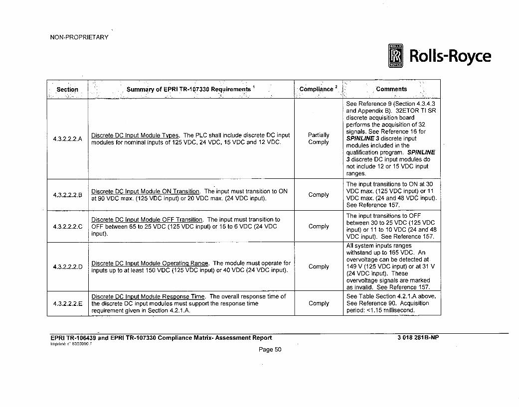
NON-PROPRIETARY
*Rolls-Royce
Section Summary of EPRI TR-1 07330 Requirements' Compliance 2 Comments
See Reference 9 (Section 4.3.4.3and Appendix B). 32ETOR TI SRdiscrete acquisition boardperforms the acquisition of 32
Discrete DC Input Module Types. The PLC shall include discrete DC input Partially signals. See Reference 16 for4.3.2.2.2.A mSPINLINE 3 discrete inputmodules for nominal inputs of 125 VDC, 24 VDC, 15 VDC and 12 VDC. Comply modules included in the
qualification program. SPINLINE3 discrete DC input modules donot include 12 or 15 VDC inputranges.
The input transitions to ON at 30Discrete DC Input Module ON Transition. The input must transition to ON VDC max. (125 VDC input) or 11at 90 VDC max. (125 VDC input) or 20 VDC max. (24 VDC input). VDC max. (24 and 48 VDC input).
See Reference 157.The input transitions to OFF
Discrete DC Input Module OFF Transition. The input must transition to between 30 to 25 VDC (125 VDC
4.3.2.2.2.C OFF between 65 to 25 VDC (125 VDC input) or 15 to 6 VDC (24 VDC Comply input) or 11 to 10 VDC (24 and 48
input). VDC input). See Reference 157.
All system inputs rangeswithstand up to 165 VDC. An
4.3.2.2.2.D Discrete DC Input Module Operating Ranqe. The module must operate for Comply overvoltage can be detected at3inputs up to at least 150 VDC (125 VDC input) or 40 VDC (24 VDC input). (24 VDC input). These
overvoltage signals are markedas invalid. See Reference 157.
Discrete DC Input Module Response Time. The overall response time of See Table Section 4.2.1.A above.4.3.2.2.2.E the discrete DC input modules must support the response time Comply See Reference 90. Acquisition
requirement given in Section 4.2.1 .A. period: <1.15 millisecond.
EPRI TR-106439 and EPRI TR-107330 Compliance Matrix- Assessment ReportIhnprimt n' 8303090 F
Page 50
3 018 281 B-NP

NON-PROPRIETARY
*Rolls-Royce
section,:, Summary of EPRI TR-07330,Requient nce 20 R eeq st .CI::•!L:•' omplian e i ,,,C. omments-, ••
Each input group is isolated forDiscrete DC Input Module Group-to-Group Isolation. The group-to-group 2000 VAC from other galvanic
4.3.2.2.2.F isolation shall be at least 600 volts peak for 125 VDC inputs or 40 volts Comply groups and mechanical groundpeak for 24 VDC inputs, linked together. See Reference
157.Discrete DC input modules are
4.3.2.2.2.G Discrete DC Input Module Class 1 E to Non-i E Isolation. The Class 1 E to N/A not intended for uselas a ClassNon-1 E isolation capability shall meet the requirements of Section 4.6.4. 1 E to N on e isoat dCe.
1 E to Non-1 E isolation device.
See Reference 25. Surge4.3.2.2.2.H Discrete DC Input Module Surge Withstand. Surge withstand shall be as Comply withstand capability meets IEC
given in Section 4.6.2. 61000-4-5 and IEC 61000-4-12.See Reference 29 Appendix H.
TTL Input Requirements. Requirements for TTL level input modules. The SPINLINE 3 system does not4.3.2.2.3 Based on exception to this requirement, Sections 4.3.2.2.3.A through N/A include TTL level input modules.
4.3.2.2.3.G are not included in this table.
4.3.2.3 Other Inputs. (section heading) --- No requirements.
See Reference 9 (Section 4.3.4.4and Appendix B). ICTO boardperforms the acquisition of two
4.3.2.3.1 Pulse Input Requirements. The PLC shall include modules that provide Comply pulse signals. See Reference 16pulse inputs. for SPINLINE 3 pulse input
modules included in thequalification program.
See Reference 9 (Section 4.3.4.4
4.3.2.3.A1 A Pulse Input Module Input Number. The module shall have at least two Comply and Appendix B). ICTO boardinputs. performs the acquisition of two
pulse signals.
EPRI TR-106439 and EPRI TR-107330 Compliance Matrix- Assessment Reporthnprinp6 n' 8303090 F
Page 51
3 018 281B-NP

NON-PROPRIETARY
* Rolls-Royce
7•Sect~ion :: Summaryof EPRI TR-m 07330 Requiremnts6 Ce -,Comments:.......... . . .. . .. . : C~om pliance• . .. ':,C m e t : "• : •
See Reference 9 (Section 4.3.4.44.3.2.3.1. B Pulse Input Module Range. The module input count frequency range shall Comply and Appendix B). Count ratebe at least 20 to 5000 Hz. range: 1 pulse/second to 6.5 106
pulses/second.Voltage: 5 V pulse inputs (3.5 V <
Pulse Input Module Operation. The input must operate for a pulse range Vih • 5 V; 0:5 Vil • 0.5 V)
4.3.2.3.1 .C of at least 3 to 28 VDC and a duty cycle of at least 20 microseconds at Exception Time : pulse width : 20 to 20090%. nanoseconds
See Reference 158.
Pulse Input Module Count Accuracy. The module shall have up and down4.3.2.3.1 .D count modes with a range of at least 9999. The accuracy of the count Exception
shall be ± 0.1%.
See Reference 158.-[
Pulse Input Module Frequency Accuracy. The module shall have a4.3.2.3.1 .E frequency mode with a range of at least 20 to 5000 Hz. The accuracy of Comply
the frequency measurement shall be ± 0.1%.
I]For generic precision, refer toReference 158.
EPRI TR-106439 and EPRI TR-107330 Compliance Matrix- Assessment ReporthinprmCn n' 8303090 F
Page 52
3 018 281 B-NP

NON-PROPRIETARY
* Rolls-Royce
-Section ' Summary of EPRI.TR-107330 Requirements Compliance 2 Comments.
Reference 9 (Section 4.3.4.4)notes that the board operatingmodes. The module responsetime depends on the project-specific application and is definedby the operation mode and by theoperating setpoints. According to
Pulse Input Module Response Time. The overall response time of the TR-107330, section 4.2.1, item A,4.3.2.3.1 .F pulse input module must support the response time requirement given in Exception the ICTO board should not be
Section 4.2.1 .A. included in the time responseevaluation. The expected timeresponse of a complete pulsecount channel would be verifiedfor the project-specific application,consistent with applicable safetyanalysis requirements. See TableSection 4.2.1 .A above.
Pulse Input Module Group-to-Group Isolation. The group-to-group Comply See Reference 158.4.3.2.3.1.G isolation shall be at least 40 VDC.
Pulse input modules are not4.3.2.3.1.H Pulse Input Module Class 1 E to Non-1 E Isolation. The Class 1 E to Non- N/A intended for uses ae Class nE to
1 E isolation capability shall meet the requirements of Section 4.6.4. Non-i E isolation device.
See Reference 25. Surge
4.3.2.3.1.1 Pulse Input Module Surge Withstand. Surge withstand shall be as given in Comply withstand capability meets IECSection 4.6.2. 61000-4-5 and IEC 61000-4-12.
See Reference 29 Appendix H.
4.3.3 Output Requirements. (section heading) --- No requirements.
EPRI TR-106439 and EPRI TR-107330 Compliance Matrix- Assessment ReportImprimne n' 8303090 F
Page 53
3 018 281B-NP

NON-PROPRIETARY
*Rolls-Royce
Section Summary of EPRI TR-107330 Requirements: Complian'e Co•. qureme 1 Comliace , Comments,
See Reference 9 (Section 4.3.4.6and Appendix B). 6SANA ISO
AnalogOutputRequirements.T C shall include modules that provide board generates up to six analog4.3.3.1 Analog Output Requirements. The PLC Comply signals. See Reference 16 for
analog outputs. SPINLINE 3 pulse input modules
included in the qualificationprogram.
4.3.3.1.A Monotonicity. The analog Ioutputs shall be monotonic to ±1/2 LSB. Comply The 6SANA ISO board ismonotonic by design.
See Reference 9 (Section 4.3.4.64.3.3.1.B Number of Channels. Each analog output module shall provide a Comply and Appendix B). 6SANA ISOminimum of four output channels. board generates up to six analog
signals,
4.3.3.1.1 Analo-g Voltage Output Requirements. (section heading) --- No requirements.
See Reference 9 (Section 4.3.4.6and Appendix B). 6SANA ISO
Analog Volta-ge Output Module Ranges. The PLC shall include analog Partially provides two kinds of voltage4.3.3.1.1.A voltage output modules with ranges of: 0 to 10 VDC, -10 to 10 VDC and 0 Comply output channels: 0/+10 V and or -
to 5 VDC. The PLC shall provide differential outputs for these ranges. C10/+10 V. SPINLINE3 analogoutput modules do not include a 0to 5 VDC output range.
See Reference 9 (Section 4.3.4.6and Appendix B). Full scale error:
4.3.3.1.1.B Analog Voltage Output Module Accuracy. Overall accuracy shall be Partially ± 0.3% at 25°C (voltage output:4 0.32% of full range. Comply 0/10 V DC). Full scale error:
+ 0.4% at 25°C (voltage output:-10/10 V DC).
4.3.3.1.1. C Analog Voltage Output Module Resolution. The minimum resolution shall Comply See Reference 91.be 12 bits.
EPRI TR-1 06439 and EPRI TR-1 07330 Compliance Matrix- Assessment ReportImprim6 n* 8303090 F
Page 54
3 018 281 B-NP

NON-PROPRIETARY
* Rolls-Royce
~~Section ~ Summrary of EPRI TR-1 0330r Rqiements Copine2p6mments
4.3.3.1.1.D Analog Voltage Output Module Load Impedance. The outputs shall Comply See Reference 91.support a load impedance of 1 kilo ohm or greater.
Analog Voltage Output Module Response Time. The overall response See Table Section 4.2.1.A above.4.3.3.1.1 .E time of the analog voltage output modules must support the response time Comply See Reference 91. Acquisition
requirement given in Section 4.2.1 .A. period: <1 millisecond.See Reference 26. Class 1 E to
Analog Voltage Output Module Isolation. The group-to-group, module-to- Non-iE isolation capability meets
4.3.3.1.1.F module and module to backplane isolation shall meet the requirements of Comply IEEE 384-1981. See Reference
Section 4.6.4. 29 Appendix J.
See Reference 25. Surge4.3.3.1.1.G Analog Voltage Output Module Surge Withstand. Surge withstand shall be Comply withstand capability meets IEC
as given in Section 4.6.2. 61000-4-5 and IEC 61000-4-12.See Reference 29 Appendix H.
4.3.3.1.2 Current Output Requirements. (section heading) --- No requirements.
See Reference 9 (Section 4.3.4.6and Appendix B). 6SANA ISOprovides one kind of current
Analog Current Output Module Ranqes. The PLC shall include analog Partially output channel: 4 to 20 mA.
4.3.3.1.2.A current output modules with ranges of: 4 to 20 mA or 0 to 20 mA, and Ply output10 to 50 mA or 0 to 50 mA. Comply SPINLINE 3 analog output
modules do not include 0 to 20
mA, 10 to 50 mA or 0 to 50 mAoutput ranges.
See Reference 9 (Section 4.3.4.64.3.3.1.2. B Analog Current Output Module Accuracy. Overall accuracy shall be Exception and Appendix B). Full scale error:
+ 0.32% of full range. + 0.4% at 25°C.
4.3.3.1.2.C Analog Current Output Module Resolution. The minimum resolution shall Comply See Reference 91.be 12 bits.
EPRI TR-1 06439 and EPRI TR-1 07330 Compliance Matrix- Assessment ReportImprim6 n' 8303090 F
Page 55
3 018 281B-NP
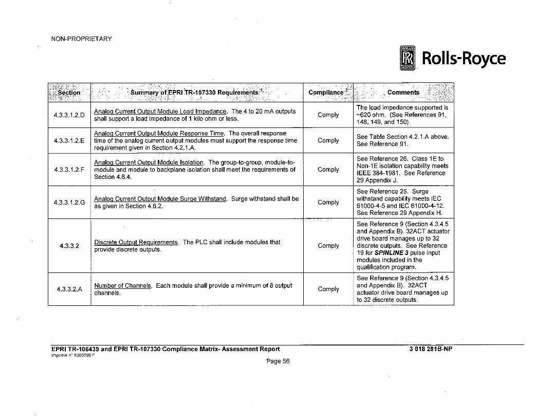
NON-PROPRIETARY
Rolls-Royce
'Section, "Summary, f EPRITR-107330 Requrmns -opinc2iComments
The load impedance supported is4.3.3.1.2.D Analol Current Output Module Load Impedance. The 4 to 20 mA outputs Comply -620 ohm. (See References 91,shall support a load impedance of 1 kilo ohm or less. 148, 149, and 150)
Analog Current Output Module Response Time. The overall response See Table Section 4.2.1.A above.4.3.3.1.2.E time of the analog current output modules must support the response time Comply See Reference 91.
requirement given in Section 4.2.1.A.See Reference 26. Class 1 E to
Analog Current Output Module Isolation. The group-to-group, module-to- Non-E isolation capa . bility meets4.3.3.1.2.F module and module to backplane isolation shall meet the requirements of Comply IEEE 384-1981. See Reference
Section 4.6.4. 29 Appendix J.
See Reference 25. Surge
4.3.3.1.2.G Analog Current Output Module Surge Withstand. Surge withstand shall be Comply withstand capability meets IECas given in Section 4.6.2. 61000-4-5 and IEC 61000-4-12.
See Reference 29 Appendix H.
See Reference 9 (Section 4.3.4.5and Appendix B). 32ACT actuatordrive board manages up to 32
4.3.3.2 Discrete O out p Reuirements. The PLC shall include modules that Comply discrete outputs. See Referenceprovide discrete outputs. 19 for SPINLINE 3 pulse input
modules included in thequalification program.
See Reference 9 (Section 4.3.4.5
4.3.3.2.A Number of Channels. Each module shall provide a minimum of 8 output Comply and Appendix B). 32ACTchannels. actuator drive board manages up
to 32 discrete outputs.
EPRI TR-106439 and EPRI TR-107330 Compliance Matrix- Assessment Reporthinprim§ n' 8303090 F
Page 56
3 018 281 B-NP

NON-PROPRIETARY
*Rolls-Royce
Section'-- Summary of EPRITR-107330oRequirements 1. Compliance 2 Comments
For 32ACT: outputs aresupervised and leakage current is1.2 mA. When put in parallel (bythe MV16), the maximum leakage
Leakage Current. Leakage current in the OFF state of non-supervised (no current is then 2.4 mA. It is less4.3.3.2.B internal ringback) modules shall be less than 80% of the minimum current Comply than the maximum leakage
needed to turn ON any digital input module. current of 10 mA tolerated by the8SRelay (type 1 or 2), which isthe only module driven by the32ACT. (See References 93, 143,and 156).SPINLINE 3 system does not
4.3.3.2.C Output Circuit Interrupter. Outputs must include a circuit interrupter. Exception provide discrete output circuitinterrupters.
Status Indication. Modules must include indicators that show the ON/OFF SPINLINE 3 system does not4.3.3.2.D status of each point. Exception provide discrete output statusindication.
4.3.3.2.1 Discrete AC Output Requirements. (section heading) --- No requirements.The SPINLINE 3 system does not
4.3.3.2.1 .A Discrete AC Output Module Types. The PLC shall include discrete AC N/A include discrete AC inputoutput modules for nominal outputs of 120 VAC and 24 VAC. modules.
Discrete AC Output Module Output Current. The output must operate with The SPINLINE 3 system does not4.3.3.2.1 .B an output current between 50 mA and 0.5 amps with an inrush capability N/A include discrete AC input
of at least 2 amps. modules.
4.332.1.C Discrete AC Output Module ON State Voltage Drop. The ON state voltage N/A The SPINLINE 3 system does notdrop shall not exceed 2 VAC at 0.5 amps. include discrete AC input
modules.
EPRI TR-106439 and EPRI TR-107330 Compliance Matrix- Assessment ReporthInprim6 n- 8303090 F
3 018 281B-NP
Page 57

NON-PROPRIETARY
*Rolls-Royce
Section Summary of EPRI TR-I07330 Requirements Compliance2 Comments
Discrete AC Output Module OFF State Leakage. The OFF state leakage The SPINLINE 3 system does not4.3.3.2.1.D curret aC ot Mod 2 Sa t N/A include discrete AC input
current shall not exceed 2 mA. modules.
Discrete AC Output Module Operating Range. The modules must operate The SPINLINE 3 system does not4.3.3.2.1 .E for point source inputs at 47 Hz to 63 Hz over the range 90 to 130 VAC N/A include discrete AC input
min. (120 VAC output). modules.
Discrete AC Output Module Response Time. The overall response time of The SPINLINE 3 system does not4.3.3.2.1 .F the discrete AC output modules must support the response time N/A include discrete AC input
requirement given in Section 4.2.1 .A. modules.
Discrete AC Output Module Group-to-Group Isolation. The group-to-group The SPINLINE 3 system does not4.3.3.2.1.G isolation shall be at least 600 volts peak for 120 VAC outputs N/A include discrete AC input
modules.
The SPINLINE 3 system does not4.3.3.2.1. H Discrete AC Output Module Class 1E to Non-iE Isolation. The Class 1Eto Non-1 E isolation capability shall meet the requirements of Section 4.6.4. modules.
Discrete AC Output Module Surale Withstand. Surge withstand shall be as The SPINLINE 3 system does not4.3.3.2.1.1 given in Section 4.6.2. N/A include discrete AC input
modules.
4.3.3.2.2 Discrete DC Output Requirements. (section heading) --- No requirements.
See Reference 9 (Section 4.3.4.5and Appendix B). 32ACT actuatordrive board manages up to 32discrete outputs. See Reference
Discrete DC Output Module Types. The PLC shall include discrete DC Partially 16 for SPINLINE 3 pulse input
4.3.3.2.2.A output modules for nominal outputs of 125 VDC, 48 VDC, 24 VDC, 15 Ply mod inlude i theVDC and 12 VDC. Comply modules included in the
qualification program. SPINLINE
3 discrete output modules do notinclude 125 VDC, 48 VDC, 15VDC, and 12 VDC output ranges.
EPRI TR-1 06439 and EPRI TR-1 07330 Compliance Matrix- Assessment ReportInprin) n' 8303090 F
Page 58
3 018 281 B-NP

NON-PROPRIETARY
* Rolls-Royce
!Section Summary of EPRI TR-1 07330 Requirements Compliance 2 Comments
See References 93, 144, and 145Discrete DC Output Module Output Current. The outputs must operate for 32ACT.
4.3.3.2.2.B with an output current between 50 mA and 0.5 amps with an inrush Comply See Reference 143 forcapability of at least 2 amps. 8SRELAY.
Exception See References 93 and 156 for32ACT. The voltage does not
4.3.3.2.2.C Discrete DC Output Module ON State Voltaqe Drop. The ON state voltage exceed 3.3 VDC at 0.5 amps.drop shall not exceed 2 VDC at 0.5 amps. See Reference 143 for
Comply 8SRELAY.
Partially See References 93 and 156 forComply 32ACT. 1.2 mA at 24 VDC.
Leakage current is roughly
Discrete DC Output Module OFF State Leakage. The OFF state leakage proportional to polarization4.3.3.2.2.D curret shalltput Mod 2 Laq voltage and stays under 2 mA
current shall not exceed 2 mA. until 40 VDC, while maximum
polarization voltage is 60 VDC.Comply Established by design for
8SRELAY.
Partially See References 93 and 156 forDiscrete DC Output Module Operating Range. The module points must Comply 32ACT (24 VDC output only).
4.3.3.2.2.E operate for source inputs of 90 to 140 VDC min. (125 VDC output), 35 to60 VDC min. (48 VDC output), and 20 to 28 VDC min. (24 VDC output). Comply See Reference 143 for
8SRELAY.See Table Section 4.2.1.A above.
Discrete DC Output Module. The overall response time of the discrete DC See Referen 92 andv9 .See References 92 and 93.
4.3.3.2.2.F output modules must support the response time requirement given in Comply Acquisition period: < 0.1Section 4.2.1 .A. millisecond.
EPRI TR-106439 and EPRI TR-107330 Compliance Matrix- Assessment ReportImprim6 n' 8303090 F
Page 59
3 018 281B-NP

NON-PROPRIETARY
*Rolls-Royce
:Section Summary of EPRI TR-107330 Requirements Compliance 2 Comments
4.3.3.2.2.G Discrete DC Output Module Group-to-Group Isolation. The group-to-group Comply Group to group isolation is 500isolation shall be at least twice nominal output. 156).
See Reference 26. Class 1 E to
4.3.3.2.2.H Discrete DC Output Module Class 1 E to Non-1 E Isolation. The Class 1 E Comply Non-1 E isolation capability meetsto Non-1 E isolation capability shall meet the requirements of Section 4.6.4. IEEE 384-1981. See Reference
29 Appendix J.
See Reference 25. Surge
4.3.3.2.2.1 Discrete DC Output Module Surge Withstand. Surge withstand shall be as Comply withstand capability meets IECgiven in Section 4.6.2. 61000-4-5 and IEC 61000-4-12.
See Reference 29 Appendix H.
4.3.3.2.3 Relay Output Requirements. (section heading) --- No requirements.
See Reference 9 (Section 4.3.4.5and Appendix B). 8SRELAY1and 8SRELAY2 relay output
4.3.3.2.3.A Relay Output Module Types. The PLC shall include relay output modules Comply modules provide normally openthat provide normally open and normally closed contacts. and normally closed contacts.
See Reference 16 for SPINLINE3 pulse input modules included inthe qualification program.
Exception Make and break switchingcapability of 1.4 A @ 220 VAC orVDC and [/R = 40 milliseconds(type 2 relays) with series
Relay Output Module Output Current. The continuous current carrying connection of contacts.4.3.3.2.3.B capacity must be at least 2 amps with make and break switching capability Make and break switching
of at least 750 VA for AC and 150 watts for DC. capability of 0.3 A @ 220 VAC orVDC and L/R = 40 milliseconds(type 1 relays).See References 143 and 159.
EPRI TR-106439 and EPRI TR-107330 Compliance Matrix- Assessment Reporthinprimn6 ný 8303090 F
Page 60
3 018 281B-NP

NON-PROPRIETARY
* Rolls-Royce
Section ~.Sumnmary of EPRI TR-4 7330 Require'ments Compliac2 Comments'
Comply See References 93, 144, and145.
4.3.3.2.3.C Relay Output Module Contact Resistance. The contact resistance shall Exception See Reference 143 (30 milliohmnot exceed 2 ohms. maximum for FD470 and
250 milliohm maximum for F480)for 8SRELAY.
4.3.3.2.3. D Relay Module Operating Range. The contacts must operate from a source Comply See Reference 143.of up to 30 VDC or 150 VAC.
Relay Output Module Response Time. The overall response time of the See Reference 9 (Appendix B).4.3.3.2.3.E relay output module must support the response time requirement given in Comply Response time is 15 milliseconds.
Section 4.2.1 .A.4.3.3.2.3. F Relay Output Module Group-to-Group Isolation. The group-to-group Comply Isolation is 1.5 kVrm, or 2.1 kV DC
isolation shall be at least 600 volts peak. (Reference 143).
See Reference 26. Class 1 E to
4.3.3.2.3.G Relay Output Module Class 1 E to Non-1 E Isolation. The Class 1 E to Non- Comply Non-1 E isolation capability meets1 E isolation capability shall meet the requirements of Section 4.6.4. IEEE 384-1981. See Reference
29 Appendix J.
See Reference 25. SurgeRelay Output Module Surge Withstand. Surge withstand shall be as given withstand capability meets IEC4.3.3.2.3.H in Section 4.6.2. Comply 61000-4-5 and IEC 61000-4-12.
See Reference 29 Appendix H.4.3.3.2.4 TTL Output Requirements. Requirements for TTL level output modules. N/A The SPINLINE 3 system does not
Sections 4.3.3.2.4.A through 4.3.3.2.4.F are not included in this table. include TTL level input modules.
4.3.4 Processor/Other System Component Requirements. (section heading) --- No requirements.
EPRI TR-106439 and EPRI TR-107330 Compliance Matrix- Assessment Reportinprimne n' 8303090 F
Page 61
3 018 281 B-NP

NON-PROPRIETARY
* RoIls-Royce
etion - Summary of EPRI TR-!107330 RequIrements Compliance" Commt s•. n :
See Table Section 4.2.1.A above.Processor Loop Time Requirements. Processor loop time shall support Analog input filter (first order): 75the response time requirement given in Section 4.2.1.A. Also, processor Hz (See Reference 9 Appendix
4.3.4.1 loop time shall be faster than the longer of the analog input conversion Comply B).time or the period associated with 2.5 times the analog filter cutoff QTS cycle time: 20 millisecondsfrequency. (See Reference 15).
Comply See References 9 (Section 4.2.3),Memory Capacity and Data Retention Capability Requirements. The 160, and 161. 2 megabytes ofmemory capacity of the main processor shall provide sufficient memory to read-only flash memory, 2execute a single application program with the number of program megabytes of write-protectedelements given. RAM for operational system
software and application software4.3.4.2 The memory used to contain the program shall be capable of retaining the Comply execution, 2 megabytes of RAM
information for a minimum of 6 months with no power applied. for data space, and 64 kilobytesof non-volatile EEPROM memory.EEPROM: Comply (100 year data
Any memory used for field modifiable constants shall be capable of at Comply retention; 100,000 write cycles)least 100,000 write cycles. Flash : (20 year data retention;
1,000,000 write cycles)
EPRI TR-106439 and EPRI TR-107330 Compliance Matrix- Assessment ReportIrnprim6 n' 8303090 F
Page 62
3 018 281 B-NP

NON-PROPRIETARY
*Rolls-Royce
Sec~tion Summary of EPRI TR-1 07330, Rqients Compliance Comments
See Reference 9 (Section4.3.2.2). The BAP businterconnects the UC25 N+ CPUboard to the different I/O boards.The UC25 N+ CPU boardcontrols the BAP bus with theSPINLINE 3 Operational SystemSoftware (OSS) through anasynchronous protocol. The datatransfer rate is included in the
Data Acquisition Requirements. The PLC shall be capable of transferring CPU cycle time. Refer to item
information between the main processor and I/O modules mounted in the Comply 4.2. 1.A
same or expansion chassis. The data transfer rate shall support the See References 46 and 51 forresponse time requirement given in Section 4.2.1 .A. generic validation testing of
SPINLINE 3 platformcommunication features.The qualification programOperability Test Procedure(Reference 27) verified that thetest specimen performed withinthe expected response times forthe test system. See Reference29 Appendices A, B, C, D, E, F,K, L, N, and 0.
Main Chassis Interconnect Device Operation. Devices used to interfaceremote or expansion chassis to the main chassis shall meet the range of Expansion chassis are not used
4.3.4.3.A environmental conditions given in Section 4.3.6. Failures of the chassis N/A for SPINLINE 3.interconnect devices shall not defeat the ability to transfer data on themain chassis.
EPRI TR-1 06439 and EPRI TR-1 07330 Compliance Matrix- Assessment ReportIrnpnm6 n 8303090 F
Page 63
3 018 281 B-NP

NON-PROPRIETARY
* Rolls-Royce
Section'Summary of EPRI TR-107330 iRequirements Compliance , 'Comments
Main Chassis Interconnect Device Failure. Failures of the chassis Expansion chassis are not used4.3.4.3.B interconnect devices shall not affect memory capacity or main processor N/A for SPINLINE 3.
data retention.
Main Chassis Interconnect Device Loss of Power. Loss of power to Expansion chassis are not used4.3.4.3.C chassis interconnect devices shall not defeat the ability to transfer data on N/A for SPINLINE 3.
the main chassis or I/O on any other chassis.
Main Chassis Interconnect Device Class 1 E to Non-i E Isolation. The Expansion chassis are not used4.3.4.3.D Class 1 E to Non-1 E isolation capability shall meet the requirements of N/A for SPINLINE 3.
Section 4.6.4.
4.3.4.3.E Main Chassis Interconnect Device Surae Withstand. Surge withstand N/A Expansion chassis are not usedshall be as given in Section 4.6.2. for SPINLINE 3.
Main Chassis Interconnect Device Data Acquisition Time. Data acquisition Expansion chassis are not used4.3.4.3.F time shall be deterministic or manufacturer shall provide information to N/A for SPINLINE 3.
establish timing effect.
4.3.4.3. G Redundant Inter-Processor Data Acquisition Backplane Busses. No requirements.Descriptive information.
4.3.4.3. G.1 Redundant Inter-Processor Data Acquisition Backplane Busses. Busses N/A The SPINLINE 3 system does notshall be at least dual redundant. use redundant backplane busses.
4.3.4.3.G.2 Redundant Inter-Processor Data Acquisition Backplane Busses. Loss of N/A The SPINLINE 3 system does notone bus shall not cause misoperation. use redundant backplane busses.
4.3.4.3.G.3 Redundant Inter-Processor Data Acquisition Backplane Busses. Loss of N/A The SPINLINE 3 system does notall busses shall not result in an indeterminate operation, use redundant backplane busses.
4.3.4.3.G.4 Redundant Inter-Processor Data Acquisition Backplane Busses. External N/A The SPINLINE 3 system does notalarm shall be activated on loss of one bus. use redundant backplane busses.
4.3.4.3.G.5 Redundant Inter-Processor Data Acquisition Backplane Busses. Data N/A The SPINLINE 3 system does notacquisition time shall be deterministic, use redundant backplane busses.
EPRI TR-1 06439 and EPRI TR-1 07330 Compliance Matrix- Assessment ReportImprini n' 8303090 F
Page 64
3 018 281 B-NP

NON-PROPRIETARY
*Rolls-Royce
'Section Summary of EPRI TR-107330 Requirements- ' Compliance 2 Comments:
Redundant Inter-Processor Data Acquisition Backplane Busses. The SPINLINE 3 system does not4.3.4.3.G.6 Operation of busses shall support the response time requirement. given in N/A
Section 4.2.1 .A. use redundant backplane busses.
Communication Port Requirements. The main processor shall provide at See Reference 9 (Sections4.3.4.4 C ommunicatio n port . Comply 4.3.2.3, 4.3.3, 4.3.4.8 and
least one communication port. Appendix B).
See Reference 9 (Sections 4.2.3and 4.3.4.8). High speed,deterministic Class 1 E digital
Communication Port Data Rate. The port shall support data rates up to communications network:4.3.4.4.A Commud. Comply NERVIA is a 10 megabit per
9600 baud. second, broadcast type networkthat implements a time-basedtoken bus communicationsprotocol.
See Reference 9 (Sections4.3.4.8, 4.5 and Table 3.6-1).The SPINLINE 3 NERVIA
4.3.4.4.B Communication Port Interface. The port shall support RS-232, RS-422, Comply communication protocol TheRS-485 or other widely used protocol. bus protocol is a time based token
bus protocol. The software isproprietary software developed byRolls-Royce. The medium isbased on IEEE Standard 802.3.
4.3.4.4.C Communication Port Connector. The port shall provide positive hold down Comply See Reference 9 Appendix B.of connectors.
EPRI TR-106439 and EPRI TR-107330 Compliance Matrix- Assessment ReportInprimne n' 8303090 F
Page 65
3 018 281B-NP

NON-PROPRIETARY
* Rolls-Royce
Section Summary of EPRI TR-107330 Requirements -. Compliance 2 Comments
UC25N+: Ethernet port (frontpanel) xl: 1500 VDC galvanicisolation. LSA - asynchronousserial link (front panel): 1500 VDC
4.3.4.4.D Communication Port Isolation. For multiple ports, the port-to-port isolation Comply isolation. See Reference 162.shall be at least 300 volts peak. I.NERVIA+: Each NERVIA
network has galvanic insulation of500 VDC. See Reference 163.Hubs galvanic isolation: 1500VAC / 2250 VDC.
Communication Port Class 1 E to Non-i E Isolation. The Class 1 E to Non- Communication ports are not4.3.4.4.E N/A intended for use as a Class 1 E to1E isolation capability shall meet the requirements of Section 4.6.4. Non-i E isolation device.
See Reference 25. Surge4.3.4.4.F Communication Port Surge Withstand. Surge withstand shall be as given Comply withstand capability meets IEC
in Section 4.6.2. 61000-4-5 and IEC 61000-4-12.See Reference 29 Appendix H.
The SPINLINE 3 system uses acoprocessor that is integral to theUC25+ CPU module. SeeReference 9 (Sections 4.3.3 and4.3.4.7 and Appendix B).
Coprocessor Module Requirements. Detailed requirements for Operation of SPINLINE 34.3.4.5 coprocessors that may be installed in I/O slots but contain local processing Comply coprocessors is invoked
capability independent of the main processor. automatically during operationindependent of any applicationsoftware program. Coprocessorprocessing capabilityperformance is inherently testedduring all qualification tests.
EPRI TR-1 06439 and EPRI TR-1 07330 Compliance Matrix- Assessment ReportInprinmi n' 8303090 F
Page 66
3 018 281B-NP

NON-PROPRIETARY
@ Rolls-Royce
ýSecion '2 Summary of EPRI TR-107330 Requirements Compliance2 Comments
Chassis Requirements. Chassis must be suitable for mounting in a See Reference 9 (Section4.3.4.6 standard 19 inch rack, and must have adequate strength and provide Comply 4.3.2.1), 21, and 76. Seepositive hold down of modules sufficient to meet seismic withstand Reference 29 Appendices E and
requirements. N.
4.3.4.7 Backup Devices/Redundancy Requirements. Descriptive information. --- No requirements.
See References 14, 15, and 27.The SPINLINE 3 qualification test
Redundant Device Requirements. Transfer to a redundant device shall specimen verified proper failover4.3.4.7.A occur within the larger of the main processor scan cycle or three data Comply to redundant power supply
conversion cycles of the failed module. components. See Reference 29Appendices A, B, C, D, E, F, K, L,N, and 0.For the case of DC/DC powersupplies: they operate in paralleland deliver approximately eachhalf of the power supply voltage.Both are continuously monitoredwith a relay device. Any required
4.3.4.7.B Redundant Device Requirements. Undetected failures in redundant Comply periodic testing of the relays willcomponents shall be detectable during periodic surveillance, be specified on a project-specific
basis in accordance with thegeneric plan to develop project-specific preventive maintenancerecommendations (Reference57).
See References 14, 15, and 14.Redundant Device Requirements. Diagnostics shall not result in The SPINLINE 3 qualification test
4.3.4.7.C indeterminate failure states and repetitive switching between redundant Comply specimen verified proper failovercomponents. to redundant power supply
components.
EPRI TR-106439 and EPRI TR-107330 Compliance Matrix- Assessment ReportImprime n' 8303090 F
Page 67
3 018 281 B-NP

NON-PROPRIETARY
Rolls-Royce
Section Summary of EPRI TR-107330 Requirements Compliance 2 Comments
See References 14, 15, and 14.
Redundant Device Requirements. Requirements for effect of transfer The SPINLINE 3 qualification test4.3.4.7.D mechanism operation on input/output module operation. Comply specimen verified proper failover
to redundant power supplycomponents.
See Reference 9 (Sections 4.4.4,Proqramminq Terminal Requirements. Special programming terminal 6.2.9, and 6.2.10). The
4.3.5 hardware or software shall meet the requirements of Sections 4.4.4, 7.7.2 Comply SPINLINE 3 programming toolsand 7.5.2. are not intended for use by the
end user.
4.3.6 Environmental Requirements. (section heading) --- No requirements.
Normal Environmental Basic Requirements. The normal PLC operatingenvironment is: See References 19 and 20.
Verified by radiation withstand4.3.6.1 Temperature Range: 16 to 400C (60 to 1040 F). Comply and environmental qualification
Humidity Range: 40 to 95% (non-condensing) testing. See Reference 29Power Source Range: As given in Section 4.6.1.1 Appendices C and D.Radiation Exposure: Up to 1000 Rads
Abnormal Environmental Basic Requirements. The abnormal PLCoperating environment is:
4.3.6.2 Temperature Range: 4 to 500 C (40 to 120 0F).Humidity Range: 10 to 95% (non-condensing)Power Source Range: As given in Section 4.6.1.1Radiation Exposure: Up to 1000 Rads
Comply
See References 19 and 20.Verified by radiation withstandand environmental qualificationtesting.. See Reference 29Appendices C and D.
+
4.3.6.3
Environmental Withstand Specific Requirements. PLC shall operate forthe temperature/humidity profile given in TR Figure 4-4 with operability asgiven in Section 5.3. Evaluations may be used to establish radiationwithstand capability.
See References 19 and 20.Verified by radiation withstandand environmental qualificationtesting. See Reference 29Appendices C and D.
EPRI TR-1 06439 and EPRI TR-1 07330 Compliance Matrix- Assessment ReportImprime n* 8303090 F
Page 68
3 018 281 B-NP

NON-PROPRIETARY
Rolls-Royce
section - Summary of EPRI TR-107330 Requirements Compliance 2 Comments
See References 22 and 24.Verified by EMC qualification
EMI/RFI Withstand Requirements. The PLC shall withstand EMI/RFI testing. See Reference 29levels given in EPRI TR-102323. When exposed to the radiated and Appendices F, G, and 0.
4.3.7 conducted test levels, the PLC processors shall continue to function, I/O Comply Additional testing from 1 - 8 GHzdata transfer shall not be interrupted, discrete I/O shall not change state, was performed in a second roundanalog I/O shall not vary more than 3%. of qualification testing, as
recommended by RegulatoryGuide 1.180, Revision 1.
See Reference 23. Verified byESD qualification testing. SeeReference 29 Appendix I. ESDTesting of the SPINLINE 3 QTSwas performed to maximum ESD
Electrostatic Discharge (ESD) Withstand Requirements. The PLC shall test levels of 8 kV for air
4.3.8 withstand ESD levels given in EPRI TR-102323 (8 kV for direct contact Ply discharges Ths leVels
discharge and 15 kV for air discharge). Comply discharges. These levelscorrespond to IEC 61000-4-2Level 3 installations. Testing tocontact discharges included thelower levels of 4 kV and 2 kV.Testing to air discharges includedthe lower levels of 4 kV and 2 kV.
EPRI TR-106439 and EPRI TR-107330 Compliance Matrix- Assessment ReportImprim& n' 8303090 F
Page 69
3 018 281 B-NP

NON-PROPRIETARY
0Rolls-Royce
Section Summary of EPRI TR-107330 Requirements Compliance 2 Comments
See Reference 21. Verified byseismic qualification testing. SeeReference 29 Appendices E and
Seismic Withstand Requirements. PLC shall be suitable for qualification N. Seismic test deficiencies wereas a Category 1 Seismic device. The PLC shall meet performance Partially resolved by a second round ofrequirements during and after exposure to OBE and SSE levels shown in Comply qualification testing. The OBETR Figure 4-5. Relay contacts of relay output modules shall not chatter. test level for some equipment was
less than the recommended value(i.e., 3.5 g ZPA versus 4.9 gZPA).
4.4 Software/Firmware. (section heading) --- No requirements.
4.4.1 Executive. (section heading) --- No requirements.
4.4.1.1 Background. Descriptive information. - - - No requirements.
Main Processor Executive Capability Requirements. The main processorexecutive shall:
A. Acquire inputs from the modules.B. Implement the application program in a continuous loop.C. Load outputs to the modules. See References 9 (Sections
4.4.1.2 D. Perform power-up and run time diagnostics. Comply 4.2.6, 4.4.4, 4.4.5, and 4.5), 46,E. Manage communications. and 48.F. Upload application programs.G. Support on-line diagnostics, maint. and troubleshooting.H. Implement the application program functions.I. Perform power-up initialize functions.J. Implement redundancy functions.
EPRI TR-106439 and EPRI TR-107330 Compliance Matrix- Assessment ReportIrnpminr nW 8303090 F
Page 70
3 018 281B-NP

NON-PROPRIETARY
*Rolls-Royce
Section Summary of EPRI TR-1 07 330.Requi~rements Compliance 2 Comment s
See References 9 (Sections4.2.6, 4.4.3.1,4.4.3.2, and 4.4.5.1and Table 3.10-1 Item B2e), 46,
Program Flow Control Requirements. Requirements for PLCs where N/A and 48.scanning of the inputs and application program execution are performed in SPINLINE 3 software operatesparallel. deterministically. Software units
The use of application program interrupts shall be restricted. The use of Comply run cyclically and sequentially. A
4.4.1.3 interrupts that result in non-deterministic application program execution fixed-duration unit cycle is always
should not be permitted. composed of the following steps:
Requirements for PLCs that implement interrupts that could result in non- Comply Self-monitoring
deterministic application program execution. Cycle time management* Data acquisition• Application processing* Data output* Local terminal management
Unintended/Unused Function Isolation Requirements. Descriptive - - - No requirements.4.4.1.4 information.
4.4.1.5 Coorocessor Executive Capability. (section heading) --- No requirements.
4.4.1.5.1 Coprocessor Executive Capability Background. Descriptive information. -- - No requirements.
he SPINLINE 3 system uses acoprocessor that is integral to theUC25+ CPU module. SeeReference 9 (Sections 4.3.3 and
4.4.1.5.2 Coprocessor Executive Capability Requirements. Requirements for Comply 4.3.4.7 and Appendix B).coprocessor resident executives or invoked utilities. SPINLINE 3 coprocessors are not
user programmable. SPINLINE 3executive software includescoding for control and operationof embedded coprocessors.
EPRI TR-106439 and EPRI TR-107330 Compliance Matrix- Assessment ReportIrnprim6 n' 8303090 F
Page 71
3 018 281 B-NP

NON-PROPRIETARY
*Rolls-Royce
Section, Summary of EPRI TR-1 07330 Requirements Compliance 2 Comments
Media Requirements. Software media provided by the manufacturer shall The SPINLINE 3 software isbe high quality and new. CD-ROMS or 3-1/2 inch floppy disks are provided on EEPROMs and can
4.4.2 acceptable. Packaging shall preclude damage during shipping. Media Comply be provided on CD-ROMs. Seeshall be clearly labeled including revision and serial number. Media shall References 94 and 95.include electronic identification.
4.4.3 Ladder Logic Requirements. Descriptive information. --- No requirements.
4.4.3.A Standard Functions. Simple normally inactive and normally active paths. Comply See References 81 and 82.
4.4.3.B Standard Functions. Transition ON/OFF (one-shot) paths. Comply See References 81 and 82.
4.4.3.C Standard Functions. Simulate break before make and make before break Comply See References 81 and 82.contact actions.
4.4.3.D Standard Functions. Coils that change paths from normal to alternate Comply See References 81 and 82.states when energized.
Standard Functions. Coils that change paths from normal to alternate4.4.3.E states when energized and remain there until the coils are de-energized Comply See References 81 and 82.
and a reset signal is applied.
4.4.31 Standard Functions. Timing functions that can be set from 0.1 seconds to Comply See References 81 and 82.2 hours.
4.4.3.G Standard Functions. Counters that perform up or down counting from at Comply See References 81 and 82.least 1 to 9999.
4.4.3.H Standard Functions. Methods to perform less than, equal to and greater Comply See References 81 and 82.than numeric comparisons.
Standard Functions. Addition, subtraction, multiplication, and division4.4.3.1 functions for integer and floating point numbers. Out of range and error on Comply See References 81 and 82.
division by zero.
4 Standard Functions. Square root, exponentiation and logarithm functions. Comply See References 81 and 82.Out of range indications.
EPRI TR-1 06439 and EPRI TR-1 07330 Compliance Matrix- Assessment ReportImprim6 n' 8303090 F
Page 72
3 018 281B-NP

NON-PROPRIETARY
* Rolls-Royce
,section Summary of EPRI TR- A07330 Requirements Compliance2 - Comments:
Standard Functions. A PID algorithm with 5 to 500% proportional band,1% resolution, 0 to 100 repeats per minute integral action, 1 repeat per The SPINLINE 3 system
4.4.3.K second resolution, anti-reset windup, 0 to 100 minutes rate action, 1 N/A application software does notsecond resolution, output limiting, out of range indication, bumpless include specific PID functions.transfer to external switch activated manual control, cascade control.
Standard Functions. A dynamic compensation function. Lead/lag ratio of The SPINLINE 3 system
4.4.3.L 0 to 10, minimum resolution of 0.05, 0.01 to 100 minute lag time, minimum N/A application software does not
1 second resolution, lead action filter. include specific lead/lagfunctions.
4.4.3.M Standard Functions. Capability to put limits on values. Comply See References 81 and 82.
The SPINLINE 3 system
4.4.3.N Standard Functions. Implement a function generator with at least five N/A application software does notslopes. include a function generator
function.
4.4.3.0 Standard Functions. Support Section 4.9.1 communications requirements. Comply See References 83 and 84.
4.4.3.P Standard Functions. Functions to capture results of self-tests. Comply See References 83 and 84.
The SPINLINE 3 system
4.4.3.Q Standard Functions. Functions to implement sequence of events N/A application software does notrequirements in Section 4.4.9. include sequence of events
functions.
4.4.3.R Standard Functions. AND, OR and XOR bit manipulation functions. Comply See References 81 and 82.
EPRI TR-106439 and EPRI TR-107330 Compliance Matrix- Assessment ReportInnprim6 n' 8303090 F
Page 73
3 018 281B-NP

NON-PROPRIETARY
* Rolls-Royce
Section. Summary of EPRI TR-107330 Requirements Compliance 2' Comments -
Parameter data used in theapplication software layer can beexported to the plant computervia a gateway (See Reference 9Section 4.5.7).Alarm and diagnostic data isexported to the MMU (See
4.4.3.S Standard Functions. Functions to store results in buffer type memory, 10 Comply Reference 9 Section 4.6.10).instances of 50 values. Facilities to transmit this data over a serial port. Individual parameter values can
be viewed by request using theLDU (See Reference 9 Section4.4.3.5.5).The LDU interface uses a serialport. The gateway and MMUinterface use the NERVIA+communication protocol.
4.4.3.T Standard Functions. Functions to implement requirements of Section Comply See References 83 and 84.
4.4.7.2.
4.4.3.U Standard Functions. Capability to attach comments to ladder logic rungs. Comply See References 83 and 84.
Software Tools Requirements. A tool shall be provided for programming, Comply See References 81, 82, 83, 84,debugging and documentation. 85, 86, and 87.
4.4.4.A Software Tools Requirements. Ability to use a host device to enter a Comply See References 83 and 84.program in the PLC.
4.4.4.A.1 Software Tools Requirements. Ability to attach explanatory comments to Comply See References 83 and 84.program steps.
4.4.4.A.2 Software Tools Requirements. Ability to store programs on removable Comply See References 83 and 84.magnetic media.
EPRI TR-106439 and EPRI TR-107330 Compliance Matrix- Assessment Report 3 018 281B-NPInprim• n' 8303090 F
Page 74

NON-PROPRIETARY
Rolls-Royce
Sectin -107330 Requireents1 om pli n Comments
4.4.4.A.3 Software Tools Requirements. Ability to perform bit by bit comparison ofprogram contained in PLC and program contained in programming device. Comply See References 83 and 84.
Software Tools Requirements. Ability to print the program contained in the4.4.4.A.4 PLC or programming device in a fashion similar in appearance to Comply See References 83 and 84.
programming device display. Include supplemental prints of programming
values.
4.4.4.A.5 Software Tools Requirements. Features to aid in I/O mapping and Comply See References 83 and 84.memory management of the PLC.
4.4.4.A.6 Software Tools Requirements. System security requirements similar to Comply See References 83 and 84.Section 4.9.2.
4.4.4.B Debugging Aids. Descriptive information. --- No requirements.
4.4.4.B.1 Debugging Aids. Ability to highlight all discrete elements not in their Comply See References 83 and 84.normal state.
4.4.4.B.2 Debugging Aids. Ability to display input, output and intermediate program Comply See References 83 and 84.values.
Debugging Aids. Ability to set constants and variables to arbitrary values, Comply See References 83 and 84.4.4.4.B.3 including values outside normal range.
4.4.4.B.4 Debugging Aids. Ability to force outputs. Comply See References 83 and 84.
4.4.4.B.5 Debugging Aids. Ability to single step through a program. Comply See References 83 and 84.
4.4.4.B.6 Debugging Aids. Ability to view the status of memory where error codes Comply See References 83 and 84.and other status information is stored.
Software Tools Requirements. Apply Configuration management Comply See Reference 52.4.4.4.C requirements per Section 7.7.3.
4.4.4.D Software Tools Requirements. Meet requirements of Sections 4.4.5.2 and Comply See Reference 52.4.4.7.2.
EPRI TR-106439 and EPRI TR-107330 Compliance Matrix- Assessment ReportIhnprim n' 8303090 F
Page 75
3 018 281B-NP

NON-PROPRIETARY
*Rolls-Royce
Section Summary:of EPRI::R-i-07330 Requirements: : : Compliance 2 Comments
4.4.4.E Software Tools Requirements. Software Verification and Validation Comply See Reference 43.requirements of Section 7.4 shall be applied to the software tools.4.4.4.F Software Tools Requirements. Provide features to aid in detecting faults Comply See References 81, 82, 83, 84,
in redundant components which are not detectable by self-diagnostics. 85, 86, and 87.
4.4.5 Configuration Identification. (section heading) --- No requirements.
4.4.5.1 Configuration Identification Background. Descriptive information. --- No requirements.
4.4.5.2 Configuration Management Aids Requirements. Descriptive information. --- No requirements.See References 9 (Sections
4.4.5.2.A Configuration Management. The PLC executive shall include a N/A 4.4.3.5.5 and 4.4.4.3) and 58retrievable, embedded electronic revision level. (Section 4.5).
The SPINLINE 3 system does not4.4.5.2.B Configuration Management. Configuration information of configurable N/A use software configurable
modules shall be retrievable in the field. modules.
See References 9 (SectionsConfiguration Management. Software tools for modifying device Comply 4.4.3.5.5 and 4.4.4.3 and Table
4.4.5.2.C configurations shall provide measures to prevent unauthorized access. 3.7.-1 Item 10, and Table 3.8-2
Item 5.9), 58, and 59.
Confi-guration Management. PLC and support tools shall provide See References 9 (Sections4.4.5.2.D capability to extract and record database information, including program Comply 4.4.3.5.5 and 4.4.4.3), 83, and 84.
constants.
Configuration Management. All PLC devices that include firmware shall Comply See Reference 88.4.4.5.2.E be marked with an identifier that includes revision level.
4.4.5.21 Configuration Management. For PLCs with redundancy, tools shall Comply See References 81, 82, 83, 84,provide capability to confirm that configurations are consistent. 85, 86, and 87.
4.4.6 Diagnostics Requirements. (section heading) --- No requirements.
EPRI TR-106439 and EPRI TR-107330 Compliance Matrix- Assessment Reportinprimne n' 8303090 F
Page 76
3 018 281 B-NP

NON-PROPRIETARY
[Rolls-Royce
Section .... Summary of EPRI TR-107330Requirements Compliance'2 Comments
General Diagqnostic Requirements. PLC must have sufficient diagnostics Comply See Reference 9 (Sections 4.4.3and test capability to detect all failures that could prevent the PLC from and 4.6). The SPINLINE 3performing its intended safety function. system does not implement
diagnostic changes in module
4.4.6.1 Items 4.4.6.1.1 through 4.4.6.1.6 must be covered by on-line self test. Comply outputs.Items 4.4.6.1.7 and 4.4.6.1.8 must be covered in power-up tests.
Short term diagnostics changes in module outputs shall be 2 milliseconds N/Aor less for DC outputs and 1/2 cycle or less for AC outputs. Capability todisable these diagnostics shall be provided.
4.4.6.1.1Processor Stall. For PLCs with redundant processors, the PLC shalldetect processor stall and halt operation of the failed processor. Comply
The SPINLINE 3 UC25+processor uses a watchdog timerfunction (See Reference 9(Sections 4.4.3 and 4.6).
SPINLINE 3 does not useredundant processors.
4.4.6.1.2 Executive Program Error. Check of executive firmware integrity using achecksum or similar test.
4.4.6.1.3 Application Program Error. Check of application program integrity using achecksum or similar test.
4.4.6.1.4 Variable Memory Error. Read/Write memory test by writing and readingback bit patterns that test both states of all bits, or similar test.
4.4.6.1.5 Module Communication Error. Check of communication data integrity.
4.4.6.1.6 Memory Battery Low. Check of memory battery capacity.
4.4.6.1.7 Module Loss of Configuration. For software configurable modules,validate configuration.
EPRI TR-1 06439 and EPRI TR-1 07330 Compliance Matrix- Assessment Reporthnprnim6 n' 8303090 F
See Reference 9 (Sections 4.4.3and 4.6).
See Reference 9 (Sections 4.4.3and 4.6).
See Reference 9 (Sections 4.4.3and 4.6).
See Reference 9 (Sections 4.4.3,4.5, and 4.6).
The SPINLINE 3 system does notuse memory batteries.
The SPINLINE 3 system does notuse software configurablemodules.
3 018 281B-NP
Page 77

NON-PROPRIETARY
* Rolls-Royce
Section Summary of EPRI TR-1 07330 Requirements Compliance 2 Comments
4.4.6.1.8 Failure of Watchdog Timer. Check of operation of watchdog timer. Comply See Reference 9 (Sections 4.4.3and 4.6).
4.4.6.1.9 Application not Executing. Failure to complete application program scan. Comply See Reference 9 (Sections 4.4.3and 4.6).
Analog Output not Following. Failure of analog output to follow Comply See Reference 9 (Sections 4.4.3,commanded value. 4.5, and 4.6).
4.4.6.1.11 Analog Input not Responding. Failure of analog input to respond to input See Reference 9 (Sections 4.4.3,signal. Comply 4.5, and 4.6).
4.4.6.1.12 Discrete Input/Output not Responding. Failure of discrete input/output to Comply See Reference 9 (Sections 4.4.3,operate correctly. 4.5, and 4.6).
Analog I/O out of Calibration. Analog input or output point out of See Reference 9 (Sections 4.4.3,4.4.6.1.13 calibration. Comply 4.5, and 4.6).
4.4.6.1.14 Power Supply out of Tolerance. Power supply to PLC is interrupted or a See Reference 9 (Sectionschassis power supply module fails. Comply 4.3.4.9 and 4.6.10).
On-Line Self-Test Requirements. On-line self-tests shall cover at least4.4.6.2 items 4.4.6.1.1 through 4.4.6.1.6 above. Results shall be made available Comply See Reference 9 (Sections 4.4.3
to the application program. and 4.6).
Power Up Diagnostics Requirements. Power up diagnostics shall includeall on-line self tests, configuration verification, and test of failure to See Reference 9 (Sections 4.4.34.4.6.3 complete a scan. Application program execution shall be inhibited if power Comply and 4.6).
up diagnostics detect a failure.
4.4.7 Data and Data Base. (section heading) --- No requirements.
4.4.7.1 Data and Data Base Overview. Descriptive information. - -- No requirements.
4.4.7.2 Data and Data Base Requirements. Descriptive information. --- No requirements.
EPRI TR-106439 and EPRI TR-107330 Compliance Matrix- Assessment Reportrnprin) n' 8303090 F
Page 78
3 018 281 B-NP

NON-PROPRIETARY
*Rolls-Royce
•Jsection !-Summary of EPRI TR-107330 Requirements 1 - Compliance 2 Comments
See References 9 (Sections 4.4.3and 4.5 and Table 3.7.-1 Items 7and 12), 46, and 47 forConsistency Blocks.
Data and Data Base Requirements. PLC shall support use of user-defined See References 9 (Sections
4.4.7.2.A program constants that are contained in non-volatile memory. Features Comply 4.4.3.5.5 and 4.4.4.3 and Table
shall confirm that constants in redundant processors are the same. 3.7.-5 Item 10) for Changeable
Parameters.SPINLINE 3 does not useredundant processors.
See References 9 (Sections 4.4.3and 4.5 and Table 3.7.-1 Items 7and 12), 46, and 47 forConsistency Blocks.
Data and Data Base Requirements. PLC shall provide functions to read See Reference 9 (Sections
4.4.7.2.B and modify data base constants. Features shall confirm that modified Comply 4.4.3.5.5 and 4.4.4.3 and Table
constants are consistent between redundant processors. 3.7.-i Item 10) for Changeable
Parameters.SPINLINE 3 does not useredundant processors.
See References 9 (Sections 4.4.3and 4.5 and Table 3.7.-1 Items 7
Data and Data Base Requirements. PLC shall provide features to prevent and 12), 46, and 47 for
4.4.7.2.C modifications to data base constants over connected communication Comply seRfence 9lSctinpaths. See Reference 9 (Sections
4.4.3.5.5 and 4.4.4.3 and Table
3.7.-1 Item 10) for ChangeableParameters.
EPRI TR-106439 and EPRI TR-107330 Compliance Matrix- Assessment ReportImprim6 n' 8303090 F
Page 79
3 018 281B-NP

NON-PROPRIETARY
* Rolls-Royce
Section Summary of EPRI TR-107330 Requirements Compliance 2 Comments
See References 9 (Sections 4.4.3and 4.5 and Table 3.7.-1 Items 7and 12), 46, and 47 for
Data and Data Base Requirements. PLC shall provide features to permit Consistency Blocks.4.4.7.2.D transmitting input, outputs and calculated values to other devices over a Comply See Reference 9 (Sections
serial port. 4.4.3.5.5 and 4.4.4.3 and Table3.7.-1 Item 10) for ChangeableParameters.Also see 4.4.3.S above.
4.4.8 Other Non-Ladder Loqic Programming Languages. (section heading) --- No requirements.
Requirements for Sequential Logic Languages. Sequential logic language See Reference 9 (Sections 4.4.4,
4.4.8.1 other than ladder logic may be used. Language shall provide capabilities Comply 6.2.9, and 6.2.10). Thegiven in Section 4.4.3. Language must support tools with features given in SPINLINE 3 programming tools
Section 4.4.4. are not intended for use by theend user.
4.4.8.2 Standard High Level Langquages. (section heading) - - - No requirements.
4.4.8.2.1 Overview of Standard Higqh Level Lanquaqes. Descriptive information. --- No requirements.
See Reference 9 (Sections 4.4.4,6.2.9, and 6.2.10). The
4.4.8.2.2 Requirements for Standard High Level Languages. Required capabilities Comply SPINLINE 3 programming toolsof supported standard high level programming languages. are not intended for use by the
end user.
4.4.9 Sequence of Events Processing Requirements. Descriptive information. --- No requirements.SPINLINE 3 status and alarm
Sequence of Events. Shall permit application program to capture, store data i stato the M lfr
4.4.9.A and time tag up to 20 transitions of up to 50 different discrete events of Exception processing and display See
inputs or application objects. Reference 9 (Section 4.6.10).
EPRI TR-106439 and EPRI TR-107330 Compliance Matrix- Assessment Reportrnprim6 n- 8303090 F
Page 80
3 018 281 B-NP

NON-PROPRIETARY
*Rolls-Royce
Sec'tion Summary of.EPRITR-107330Requirements Compliance' Commennts
SPINLINE 3 status and alarm
4.4.9.B Sequence of Events. Shall permit starting and stopping the event N/A data is sent to the MMU forrecording. processing and display See
Reference 9 (Section 4. 6.10).
4.4.9.C Sequence of Events. Shall permit transmitting the data to an external Comply See Reference 9 (Section 4.5.7).
device using a PLC communication port.
SPINLINE 3 status and alarm
4.4.9.D Sequence of Events. Relative accuracy of time tags shall be one scan N/A data is sent to the MMU forcycle ± 50 msecs. processing and display See
Reference 9 (Section 4. 6.10).
See Reference 9 (Sections 6.2and 6.4).See References 46 and 51 forgeneric platform integration
System Integration Requirements. An appropriate level of system testing.
4.4.10 integration and integration testing shall be applied to the test specimen Comply See r s5 n 6
and TSAP. See References 53 and 56 forproject specific integration testingrequirements.See References 64 and 69 forTSAP integration testing.
4.5 Human/Machine Interface (HMI). (section heading) --- No requirements.
4.5.1 Human/Machine Interface (HMI) Backqround. Descriptive information. -- - No requirements.
4.5.2 Requirements for Human/Machine Interface Functions._Descriptive --- No requirements.information.
HMI Functions. PLC shall support switching a loop controller between The SPINLINE 3 system does not4.5.2.A manual and automatic via switch inputs. For control loops with integral N/A provide operator workstations for
action, auto/manual tracking shall be provided, loop controllers.
EPRI TR-1 06439 and EPRI TR-1 07330 Compliance Matrix- Assessment Reporthnprim& n' 8303090 F
Page 81
3 018 281 B-NP

NON-PROPRIETARY
*Rolls-Royce
secti I on Suimmaryo0fEPRI TR- 07330 Requirementsi comiliance 2: Comments'
HMI Functions. PLC shall support setpoint adjustments via switch inputs. The SPINLINE 3 system does not4.5.2.8 Adjustments shall include increase, decrease, and rate of change of N/A provide operator workstations for
setpoint. controller setpoint adjustments..
See Reference 9 (Section4.2.4.2). Manual initiation of
HMI Functions. PLC shall support manual initiation of equipment via protection functions is a project-4.5.2.C switch inputs. PLC shall support detection of manually initiated Comply specific system design issue.
equipment. The SPINLINE 3 system supportscompletion of protective actionsfor manual initiation signals.
See Reference 9 (Section4.2.4.2). Display of safety
4.5.2.D HMI Functions. PLC shall support display of status of discrete and Comply parameters is a project-specificcontinuous value parameters via connected devices, system design issue. The
SPINLINE 3 system supportsdisplay of safety parameters.
HMI Functions. PLC shall support sending information to a serial port4.5.2.E device. Information sent shall include input, output and internal variable Comply See References 9 (Section 4.5.7)Values, on-line diagnostics, sequence of events (SOE) data, and results of and 15.
calculations, comparisons and bit manipulations.
Requirements for Interactive Features. The PLC shall provide Comply See References 1 (Sectionsmechanisms to prevent unauthorized access to or inadvertent use of 4.4.3.5.5 and 4.4.4.3 and Tableon-line functions. 3.7.-1 Item 10, and Table 3.8-2
Item 5.9), 58, and 59.4.5.3 Interactive features shall be available through a programming, Comply
maintenance and debugging port. PLC shall operate with no connection tothis port.
PLC shall mask interactive commands during run mode. Comply
EPRI TR-106439 and EPRI TR-107330 Compliance Matrix- Assessment ReportImprim• n' 8303090 F
Page 82
3 018 281B-NP

NON-PROPRIETARY
* Rolls-Royce
Section Summary of EPRI TR-i)07330• Requirements Compliance ' Comments
Requirements for Operator Action System Response Times. For any The SPINLINE 3 system does not4.5.4 operator action that requires PLC confirmation, the PLC shall include N/A provide operator workstations for
features to enable confirmation within 0.5 seconds. loop controllers.
See Reference 9 (Appendix B).4.5.5 Display Requirements. LEDs are acceptable for any status displays. Comply Displays on modules are provided
by LCDs and LEDs.
4.5.6 Alarm Processing Requirements. Descriptive information. - -- No requirements.
4.5.6.A Alarm Processing. PLC shall have ability to compare inputs or derived Comply See References 9 (Sectionparameters to setpoints. 4.6.10), 81, and 82.
Alarm Processing. PLC shall have ability to latch an alarm condition and See References 81 and 82.4.5.6.B rm Pron alarm condition. Comply Alarms require interface with plantreset based on alarm reset condition. alarm system.
See References 81 and 82.4.5.6.C Alarm Processing. PLC shall have ability to blink an output indicator. Partially Alarms require interface with plantComply alarm system for blink capability.
See References 81 and 82.Partially Alarms require interface with plant4.5.6.D Alarm Processing. PLC shall have ability to acknowledge an alarm. Comply alarm system for actuation and
reset controls.
4.5.6.E Alarm Processing. Application program shall have ability to capture Comply See Reference 9 (Sectionresults of self-diagnostics. 4.6.10).
Alarm Processing. Application program shall have ability to store results4.5.6.F of items A through E in a buffer and transmit the data via a communication Comply See Reference 9 (Section 4.5.7).
port.
4.5.7 Hard Manual Backup. Descriptive information. --- No requirements.
4.6 Electrical. (section header) --- No requirements.
4.6.1 Power Supply Requirements. (section heading) No requirements.
EPRI TR-106439 and EPRI TR-107330 Compliance Matrix- Assessment ReportIrnprim6 ný 8303090 F
3 018 281B-NP
Page 83

NON-PROPRIETARY
* Rolls-Royce
Section. Summary of EPRI TR-1 07330 Requirements Compliance 2 Comments
4.6.1.1 PLC Power Sources and Power Supply Requirements. Descriptive No requirements.information.
Power Sources. AC sources shall operate from at least 90 VAC to See References 14, 15, 27. and4.6.1.1 .A 150 VAC and 57 to 63 Hz. AC sources shall operate at the temperature Comply 29 Appendix D.
and humidity range given in Section 4.3.6.
See References 14, 15, 27, and________ 204 VD to29 Appendix D. ALIM 48 V / 5V -
Power Sources. DC sources shall operate from at least 20.4 VDC to supp ly boar
4.6.1.1 .B 27.6 VDC. DC sources shall operate at the temperature and humidity Exception 24 V power supply boardrang gien n Setio 4..6.powered by internal power
range given in Section 4.3.6. supplies connected to 120 VAC.
See Table Item 4.6.1.1.A above.
See References 14, 15, 27. and29. ALIM 48 V / 5 V - 24 V powersupply board powered by internal
4.6.1.1.C Power Sources. DC sources shall operate for seven days from a 30 VDC Exception power supplies connected to 120source. VAC. See Table Item 4.6.1.1.A
above. Duration of overvoltageconditions as specified in the testprocedures.
The power capacity will bechecked against the calculated
Power Sources. Sources shall be capable of supplying 1.2 times bus Exception power consumption for the4.6.1.1 .D loading for a fully loaded main chassis. project-specific application,
consistent with applicable safetyanalysis requirements.
4.6.1.1. E Power Sources. Sources shall be capable of supplying 1.2 times bus N/A Expansion chassis are not usedloading for a fully loaded expansion chassis. for SPINLINE 3.
EPRI TR-106439 and EPRI TR-107330 Compliance Matrix- Assessment ReportImprim& n 8303090 F
Page 84
3 018 281 B-NP

NON-PROPRIETARY
* .Rolls-Royce
SSection Summary of EPRI TR-1 07330 Requirements. Compliance62 Comments:~
See Reference 27. Verified byqualification program Operability
4.6.1.1.F Power Sources. Hold up time for AC supplied power sources shall be 40 Comply Test Procedure. See Referencemsec. 29 Appendices A, B, C, D, E, F,
K, L, N, and 0.
See Reference 25. Surgewithstand capability meets IEC61000-4-5 and IEC 61000-4-12.See Reference 22. Verified byEMI/RFI, Surge withstand, and
Power Sources. Sources shall meet the EMI/RFI, surge withstand and Comply ESD qualification testing. See4.6.1.1 G ESD requirements of Sections 4.3.7,'4.6.2 and 4.3.8. Reference 29 Appendices F, G, I,
and 0.Sources shall meet the grounding requirements of Section 4.6.8. Comply Grounding of the QTS and test
system is in accordance with themanufacturer recommendations(Reference 96). This groundingconfiguration met MIL-STD-461 Eand IEC 61000 requirements.
See References 9 (Section4.6.1.1 .H Power Sources. Requirements for fan cooled power sources. Comply 4.3.4.3) and 15.
Power Sources. Faults in redundant power sources shall not prevent See References 9 (Section4.6.1.1.1 oper ource alternaredupply. Comply 4.3.4.9), 27, and 29 Appendices
operation of the alternate supply. A, B, C, D, E, F, K, L, N, and 0.
EPRI TR-106439 and EPRI TR-107330 Compliance Matrix- Assessment ReportInprir6 n' 8303090 F
Page 85
3 018 281 B-NP
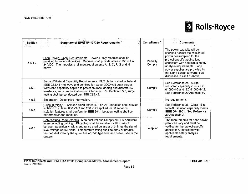
NON-PROPRIETARY
* Rolls-Royce
Section Summary of EPRI TR-107330 Requirements Compliance Comments
The power capacity will bechecked against the calculated
Loop Power Supply Requirements. Power supply modules shall be power consumption for the4.6.1.2 provided for external devices. Modules shall provide at least 500 mA at Partially project-specific application,
consistent with applicable safety24 VDC. The modules shall meet requirements A, B, C, F. G and H Comply analysis requirements. Loop
above.anlssrqieet.Lo power supplies are provided bythe same power converters asdiscussed in 4.6.1.1 above.
Surae Withstand Capability Requirements. PLC platform shall withstand See Reference 25. SurgeIEEE C62.41 ring wave and combination wave, 3000 volt peak surges. withstand capability meets IEC
4.6.2 Withstand capability applies to power sources, analog and discrete I/O Comply 61000-4-5 and IEC 61000-4-12.interfaces, and communication port interfaces. Per Section 6.3.5, surge See Reference 29 Appendix H.testing shall be conducted per IEEE C62.45.
4.6.3 Separation. Descriptive information. --- No requirements.
Class 1 E/Non-1 E Isolation Requirements. The PLC modules shall provide See Reference 26. Class 1 E to4.6.4 isolation of at least 600 VAC and 250 VDC applied for 30 seconds. Comply Non-1 E isolation capability meets
Isolation features shall conform to IEEE 384. Isolation testing shall be IEEE 384-1981. See Reference
performed on the modules. 29 Appendix J.
Cable/Wirinq Requirements. Manufacturer shall supply all PLC hardware The requirements for each powerinterconnecting cabling. All cabling shall be suitable for UL Class 2 plant can vary and must be
4.6.5 service. Specifically, withstand rating shall be larger of 3 times the signal verified for the project-specificlevel voltage or 150 volts. Temperature rating shall be 600C or greater. Exception application, consistent with
Vendor shall identify the quantities of PVC type wire and cable used in the applicable safety analysissystem. II requirements.
EPRI TR-1 06439 and EPRI TR-1 07330 Compliance Matrix- Assessment ReportImprim6 n' 8303090 F
Page 86
3 018 281B-NP

NON-PROPRIETARY
R Rols-oc
Section summary of EPRI TR-1 07330 Requiremen - 'Compliance 2 Comments
Termination Requirements. Modules shall be able to be removed without Comply See References 9 (Section 4.3disconnecting field wiring, and Appendix B), 15, and 16.
Features shall be provided to substitute test signals or monitoring Comply4.6.6 instruments for field connections. Connectors to the PLC shall have
positive hold down mechanisms.
Connectors and terminations to the PLC shall be qualified with the generic Comply
PLC.
4.6.7 Backup Power. Descriptive information. --- No requirements.
Groundinq/Shieldinq Requirements. The PLC equipment shall meet Comply See Reference 96.IEEE 1050 and EPRI TR-102323 grounding requirements. This includessupporting connection to single point, multi-point and floating groundsystems, and providing separate ground connection points on each
4.6.8 chassis for AC ground, DC ground, and signal ground.
The PLC equipment shall meet IEEE 1050 and EPRI TR-1 02323 shieldingrequirements. This includes providing shielding connection points for theI/O module field terminations.
4.7 Maintenance. (section heading) --- No requirements.
4.7.1 Maintenance Background. Descriptive information. --- No requirements.
4.7.2 Diagnosis/Built-in Testability Requirements. Descriptive information. --- No requirements.
EPRI TR-106439 and EPRI TR-107330 Compliance Matrix- Assessment Reportrnprimne n' 8303090 F
Page 87
3 018 281B-NP

NON-PROPRIETARY
* Rolls-Royce
Section Summary of EPRI TRA 07330 Requirements.' Compliance 2 Comments
Module Replacement Requirements. The PLC shall contain features to Comply See Reference 57 for genericaid in module replacement. template to prepare this
information for each project.The maintenance manual shall contain a description of any hardwareconfiguration item for each module.
The module hold downs shall be easily accessible and provide ease ofremoval and reinstallation.
Preventive Maintenance Requirements. Equipment manuals shall contain See Reference 57 for generic
4.7.4 preventive maintenance information. Preventive maintenance shall also Comply template to prepare this
include components identified in Section 4.7.8.2. information for each project. Seealso Table Section 4.7.8.2.
Surveillance Testing Requirements. The PLC shall support IEEE 338 Comply See Reference 9 (Section 4.6).surveillance testing through:
- Ability to read input, intermediate and output values.- Ability to force output values.
4.7.5 - Ability to make connections to all I/O signals.- Ability to program I/O operations.
Features and procedures shall be provided that permit detection of failures Complyof all redundant components if those failures are not detectable by self-diagnostics or'are masked by redundant channel behavior.
4.7.6 Output Bypass/Control Devices. Descriptive information. --- No requirements.
Hot Repair Capability. The PLC shall support installing I/O modules with The SPINLINE 3 system does not
4.7.7 backplane power applied. Low power modules shall support removal with N/A support on-line removal orfield power applied. When output modules are removed from the installation of components.backplane, the state of the outputs should be known.
4.7.8 Manufacturer System Life Cycle Maintenance. (section heading) --- No requirement.
EPRI TR-106439 and EPRI TR-107330 Compliance Matrix- Assessment ReportInprim, n' 8303090 F
3 018 281 B-NP
Page 88

NON-PROPRIETARY
@ Rolls-Royce
'Secti 6n Smayof EPRI.TR-7107330-R~e'quirem'ents Compliance,2 Comments
Parts Replacement Life Cycle Requirements. The baseline configuration Comply See Reference 16.of the qualified PLC shall be established. See Reference 9 (Table 3.2-1
Items Ill - Design Control).Records shall be maintained for revision history and changes. See Table Section 7.8.
4.7.8.1Records shall be maintained for tracking failures.
Testing shall be performed as necessary to maintain a qualified platformbased on future revisions or replacements.
See Reference 9 Section 5.2 andReferences 30 - 41 demonstratethat the predicted reliability forSPINLINE 3 modules are greaterthan the typical nuclear plantsurveillance intervals used todetect failures.Reference 57 contains thegeneric plan to develop project-
Component Aqing Analysis Requirements. A periodic surveillance and specific preventive maintenance
4.7.8.2 maintenance interval shall be determined per IEEE 323 to account for any Comply recommendations for any
significant aging mechanisms. components with limited life (e.g.,batteries, air filters, or electrolyticcapacitors).Regulatory Position C.1 of NRCRegulatory Guide 1.209 does notrequire the age conditioning inIEEE Std. 323-2003 Section6.2.1.2 to be applicable becauseof the absence of significantaging mechanisms onmicroprocessor-based modules.
EPRI TR-1 06439 and EPRI TR-1 07330 Compliance Matrix- Assessment ReportInprime n° 8303090 F
Page 89
3 018 281 B-NP

NON-PROPRIETARY
*Rolls-Royce
Section 'Summary of EPRITR- 07330 Requirements Compliance 2 Comments
4.7.9 Maintenance Human Factors. Descriptive information. --- No requirements.
See Reference 57 for generic4.7.9.A Special PLC Manufacturer Equipment. The manufacturer shall provide Comply template for project-specificdocumentation for PLC support equipment. operating and maintenance
documentation.
Test Equipment Connections. Test equipment connections shall be See Reference 57 for generic
4.7.9.1B supported by documentation and hardware, including interconnection Comply template for project-specificdevices. The manufacturer shall provide any special instruction for use of operating and maintenancetest equipment connections. documentation.
See Reference 57 for generic
4.7.9.C Job Aids. Aids for operating the PLC equipment shall be provided. Comply template for project-specificoperating and maintenancedocumentation.
See Reference 57 for generic
*4.7.9.D Help Screens. Help screens for software used to support maintenance Comply template for project-specificshall be provided. operating and maintenance
documentation.
Requirements for Third Party/Sub-Vendor Items. All items provided by
4.8 sub-vendors or third parties shall be subjected to all applicable Comply See References 9 (Section 4.3requirements and tests. Compatibility of operation with the PLC shall be and Appendix B), 14, 15, and 16.demonstrated through tests.
4.9 Other. (section heading) --- No requirements.
4.9.1 Data Handlinq and Communication Interface Overview. Descriptive --- No requirements.information. --- N eurmns
EPRI TR-106439 and EPRI TR-107330 Compliance Matrix- Assessment ReportImprim6 n' 8303090 F
Page 90
3 018 281 B-NP

NON-PROPRIETARY
*Rolls-Royce
Section Summary of EPRI TR- 073 euremet Compliance Comments
Peripheral Communication Requirements. The PLC executive and/orapplication software tools shall provide features to prevent loss of serialcommunication from degrading the application program. Communication See References 9 (Sections 4.4
4.9.1.1 overhead time shall be deterministic. Peripheral communications shall Comply and 4.5 and Table 3.7-i), 46, 48,support at least 1000 character communication buffers. (Note: 1 50, and 4.5character = 1 byte. A real variable uses 8 bytes or eight characters). 50, and 51.Serial communications shall support checksum (or equivalent) data qualitychecks. Requirements for redundant communication hardware.
4.9.1.1.1 Software Isolation Requirements. Descriptive information. --- No requirements.See References 9 (Sections 4.4
4.9.1.1.1 .A Software Isolation. Features shall be provided to permit sending serial Comply and 4.5 and Table 3.7.-i), 46, 48,port data with no hardware or software handshaking. 50, and 51.
Software Isolation. Features shall be-provided to permit the application See References 9 (Sections 4.4program to ignore communication port incoming data. 50, and 51.
See References 9 (Sections 4.44.9.1.1.1.C Software Isolation. Software shall permit use ofthe send data functions Comply and 4.5 and Table 3.7.-1), 46, 48,with the receive data functions disabled. 50, and 51.
See References 9 (Sections 4.44.9.1.1.1. D Software Isolation. Features shall be provided to disable interrupts caused Comply and 4.5 and Table 3.7.-1), 46, 48,by full serial port receive buffers. 50, and 51.
EPRI TR-106439 and EPRI TR-107330 Compliance Matrix- Assessment ReportImprim6 n' 8303090 F
Page 91
3 018 281 B-NP

NON-PROPRIETARY
*Rolls-Royce
Smection .ummary of EPRI tR-107330 Requirements Compliance Comments
PLC Peer-to-Peer Communication Requirements. Peer-to-peer link shallmeet requirements of Section 4.3.4.4, except item B. Communication timeshall be deterministic. Communication errors shall not affect otherportions of the application program or inhibit the PLC scan cycle. Queues See References 9 (Sections 4.4
4.9.1.2 for communicated data shall be supported and queue status shall be Comply and 4.5 and Table 3.7.-1), 46, 48,available to the communication program. Loss of communication shall be 50, and 51.detected and made available to the application program. Use of the peer-to-peer communication link shall support the response time requirementgiven in Section 4.2.1.A.
Overall System Security Requirements. Switching the main processor N/A See References (Sectionsfrom RUN mode to other modes shall be by keylock switch. 4.4.3.5.5 and 4.4.4.3 and Table
3.7.-1 Item 10, and Table 3.8-2Features shall ensure that redundant components operate in the same N/A Item 5.9), 58, and 59.mode, and that program changes are loaded into all redundant The SPINLINE 3 system does not
4.9.2 processors. utilize key switches to change theoperating mode of the
Provisions shall prevent modification of the application program and Comply processors. (See Reference 9operating system while the PLC in on-line. Section 4.4.3.4).
SPINLINE 3 does not useredundant processors.
EPRI TR-106439 and EPRI TR-107330 Compliance Matrix- Assessment Reportbnprinm n' 8303090 F
Page 92
3 018 281B-NP

NON-PROPRIETARY
* Rolls-Royce
'•i i 107330 RequirementsSection Summary of EPRI TR-107330 irements Compliance 2 Comments
See Reference 66. On eachcycle, TSAP1 increments by 1 thevalue of counter and sends it toTSAP2 and DAS via networkconnections. Each cycle, TSAP1receives a counter from TSAP2(which has been incremented by8) and sends it for information toDAS via the network. Each cycle,
Heartbeat Requirements. The PLC shall provide capability to activate a Comply TSAP1 checks the validity of data"heartbeat" external to the PLC. received from TSAP2 and
elaborates one global invalidityindicator for the networkconnection if there is at least oneinvalid datum. This informationcan be used to diagnose anynetwork problem identifiedthrough NERVIA self-tests (i.e.,the Consistency Blockrefreshment indicator).
Hazardous Materials Requirements. Material data sheets shall be No hazardous materialsprovided for all hazardous materials associated with the PLC. systems.
4.10 Shippinq and Handlinqi Requirements. Packaging and shipping shall be in Comply See References 62, 78, and 79.
accordance with ANSI N45.2.2.
4.10.1 Packa~qinq Requirements. Descriptive information. - - - No requirements.
Items Shipped. Shall be packaged to avoid damage or degradation due to4.10.1.A various environmental and handling factors which may be encountered Comply See References 62, 78, and 79.
during shipping and storage.
4.10.1.B Items Shipped. Packaging shall include desiccant materials as required. Comply See References 62, 78, and 79.
EPRI TR-1 06439 and EPRI TR-1 07330 Compliance Matrix- Assessment Reporthnprnim6 n' 8303090 F
Page 93
3 018 281B-NP

NON-PROPRIETARY
* Ro Is-Royce
-Section Summary of EPRI TR-107330 Requirements Compliance Comments
Items Shipped. Items shall be inspected for cleanliness prior to4.10.1.C packaging. Items not immediately packaged shall be protected from Comply See References 62, 78, and 79.
contamination.
Items Shipped. Cushioning shall be provided to protect against shock and Comply See References 62, 78, and 794.10.1 .D vibration.
4.10.1. E Items Shipped. Items and containers shall be marked with appropriate Comply See References 62, 78, and 79identification.
4.10.1.F Items Shipped. Copies of packing lists shall be included with each carton Comply See References 62, 78, and 79shipped.
4.10.1.G Items Shipped. ESD sensitive items shall be appropriately packaged, Comply See References 62, 78, and 79handled and marked.
4.10.1.H Items Shipped. Packaging shall be suitable for movement using hand Comply See References 62, 78, and 79trucks.
4.10.1.1 Items Shipped. Special handling or storage requirements shall be marked Comply See References 62, 78, and 79
on the containers.
The SPINLINE 3 systems do not4.10.1.J Items Shipped. See Section 4.4.2 for requirements for software storage N/A provide software media for utilitymedia. se
use.
Shippinq Requirements. Requirements for mode of shipping, use of fully4.10.2 enclosed vehicles, special handling and stacking instructions as Comply See References 62, 78, and 79
necessary, and container markings and protective covers.4.10.3 Storage Requirements. Storage and shelf life requirements shall be Comply See References 62, 78, and 79
provided for all PLC items.
5 Acceptance/Operability Testing. Descriptive information. --- No requirements.
5.1Acceptance/Operability Testinq Overview. The development, design andperformance of acceptance testing shall use the documentationrequirements of Section 8.14.
Comply See References 14 and 17 - 28.
EPRI TR-1 06439 and EPRI TR-1 07330 Compliance Matrix- Assessment ReporthInprim6 n' 8303090 F
Page 94
3 018 281 B-NP

NON-PROPRIETARY
*Rolls-Royce
Section Summary of EPRI TR-107330 Requirements Compliance Comments
5.2 Pre-Qualification Acceptance Test Requirements. Descriptive information. --- No requirements.
Reference 9 (Section 6.2.9) andReferences 43 and 45. Thequalification of the application
Application Objects Testing. Testing of the software objects in the PLC objects (SCADE Function Blocks)
5.2.A library shall be performed. This testing shall be in addition to any testing Exception wbas o n cthe softwarperfrme by he anufctuer.was based on the software
performed by the manufacturer. development process (including
independent verification andvalidation) of the Function Blocks.
5.2.IB Initial PLC Calibration. The generic qualification sample PLC shall be Comply See References 14, 17, 18, andcalibrated to NIST traceable sources. Copy 29.
5.2. C System Integration. System integration testing portion of TSAP V&V shall Comply See Reference 69.be performed during acceptance testing.
5.2.D Operability Tests. The Operability Test shall be performed during Comply See References 14, 17, 27, andacceptance testing. 29 Appendix A.
Prudency Tests. The Prudency Test shall be performed during Comply See References 14, 17, 28, and5.2.E acceptance testing. 29 Appendix A.
EPRI TR-1 06439 and EPRI TR-1 07330 Compliance Matrix- Assessment Reporthrnprimn6 n' 8303090 F
Page 95
3 018 281B-NP

NON-PROPRIETARY
*Rolls-Royce
sec tion Summary of EPRI TR-107330 Requirements Compliance2 Comments'
See Reference 14. Thesequence of testing does notinclude Burn-In Testing. TheSPINLINE 3 platformmanufacturing process includesroutine burn-in of platformhardware. In addition to theroutine burn-in during themanufacturing process, the QTSwas subjected to the FactoryAcceptance Test and the Pre-
Burn-inTes. A minimum 352 hour burn-in test shall be performed during Qualification Acceptance Testing,5.2.F Burn-In Test. ing Exception as described in Reference 29.
acceptance testing. The Pre-Qualification AcceptanceTesting sequence included bothOperability and Prudency Testing.This testing was performed priorto transportation of QTS to thequalification test facility andrepresents additional burn-in timefor the test specimen. It meetsthe intent of this requirement todetect early life failures duringPre-Qualification Testing throughperformance of Burn-In Testing.
5.3 Operability Test Requirements. Descriptive information. --- No requirements.
See References 27 and 29Appendices A, B, C, D, E, F, K, L,
Accuracy. Accuracy checks shall be performed on the analog input/output Comply N, and 0. Verified by qualification5.3.A modules.
program Operability TestProcedure.
EPRI TR-106439 and EPRI TR-107330 Compliance Matrix- Assessment Reporthmnprim n' 8303090 F
Page 96
3 018 281 B-NP

NON-PROPRIETARY
ERolls-Royce
Section 1mayo PR1,130R ieet Compliance 2 ~ Comments
The qualification program
Response Time. Response time of analog input to digital output and Operability Test Procedure
digital input to digital output sequences shall be measured. For baseline (Reference 27) verified that the
5.3.B (acceptance) testing, the acceptance criteria is that the measured Comply the expected response times forresponse time shall not vary more than 20% from the value calculated the test system (Reference 29
from manufacturer's data. For all subsequent testing, the measured value Appendices A, B, C, D, E, F, K, L,
shall not vary more than 10% from the baseline. Append A, B, C, SEctionvary N, and 0). See Table Section
4.2.1.A above.
See Reference 27. Verified byqualification program Operability
5.3.C Discrete Input Operability. Discrete inputs shall be tested for capability to Comply Test Procedure (Reference 29Sdetect changes in the inputs. Appendices A, B, C, D, E, F, K, L,
N, and 0).
See Reference 27. Verified by
Discrete Output Operability. Discrete outputs shall be tested for ability to qualification program Operability5.3.D operate within rated voltages and currents. Comply Test Procedure (Reference 29
Appendices A, B, C, D, E, F, K, L,N, and 0).
EPRI TR-1 06439 and EPRI TR-1 07330 Compliance Matrix- Assessment Reportinprim6 n' 8303090 F
Page 97
3 018 281 B-NP

NON-PROPRIETARY
*Rolls-Royce
Section Summary of EPRI R-107330 Require.ments Compliance 2 Comments
The communication Operabilitytests described in EPRI TR-107330, Section 5.3.E are notapplicable to this fiber opticcommunication interface. Instead,the NERVIA+ fiber opticcommunication interface wasconnected and exercisedcontinuously by the TSAP
Communication Operability. If any communication functions are included throughout prequalification and
5.3.E in the qualification envelope, then operability of the ports shall be tested. Exception qualification testing. DataTests shall look for degradation in bit rates, signal levels and pulse shapes transmitted through the interfaceof communication protocol. was monitored continuously
during testing and checked forconsistency with the operation ofthe TSAP. Any failures of theNERVIA+ fiber opticcommunication interface wasimmediately indicated by the testsystem data acquisition system.See Reference 29 Appendices A,B, C, D, E, F, K, L, N, and 0.
EPRI TR-106439 and EPRI TR-107330 Compliance Matrix- Assessment Reporth'nprim6 nW 8303090 F
Page 98
3 018 281 B-NP

NON-PROPRIETARY
*Rolls-Royce
Summary ofEPRI TR-107330 Requirements 1 Compliance 2 Comments
The SPINLINE 3 system uses acoprocessor that is integral to theUC25+ CPU module. SeeReference 9 (Sections 4.3.3 and
Coprocessor Operability. If any coprocessors are included in the 4.3.4.7 and Appendix B).qualification envelope, then tests shall be performed specifically on these Comply Coprocessor processingcoprocessors. capability performance is
inherently tested during allqualification tests. Separatecoprocessor qualification tests arenot required.
See Reference 27. Verified byqualification program Operability
Timer Tests. Accuracy of timer functions shall be tested. N/A Test Procedure. See Reference29 Appendices A, B, C, D, E, F,K, L, N, and 0.
EPRI TR-106439 and EPRI TR-107330 Compliance Matrix- Assessment Reporthnprine n' 8303090 F
Page 99
3 018 281 B-NP

NON-PROPRIETARY
* Rolls-Royce
ý.'-Section Summary of EPRI TR-107330 Requirements Compliance 2 Comments
The functions of the QTSmechanisms to detect a failure tocomplete a scan (the watchdogtimers) are checked duringhardware diagnostics performedon power-up of the QTS. If afailure of a watchdog timermechanism is detected, the testspecimen power-up will stop and
Test of Failure to Complete Scan Detection. The function of the a diagnostic fault indication will be5.3.H mechanism to detect failure to complete a scan shall be tested. The Comply generated. Therefore, successful
power up testing of this feature may be used to establish its operability, restart on restoration of powerindicates proper functioning of theQTS watchdog timermechanisms. The QTS ispowered down and restarted atseveral points throughoutOperability testing. Therefore, thisprocedure does not include aseparate test of the watchdogtimer mechanism function.
See References 14, 15, and 27.The SPINLINE 3 qualification test
Failover Operability Tests. If redundancy with automatic transfer to a specimen verified proper failover5.3.1 redundant device is used, tests shall be performed to establish operability Comply to redundant power supply
of the failover hardware. components. See Reference 29Appendices A, B, C, D, E, F, K, L,N, and 0.
EPRI TR-106439 and EPRI TR-107330 Compliance Matrix- Assessment ReportImprimr n' 8303090 F
3 018 281 B-NP
Page 100
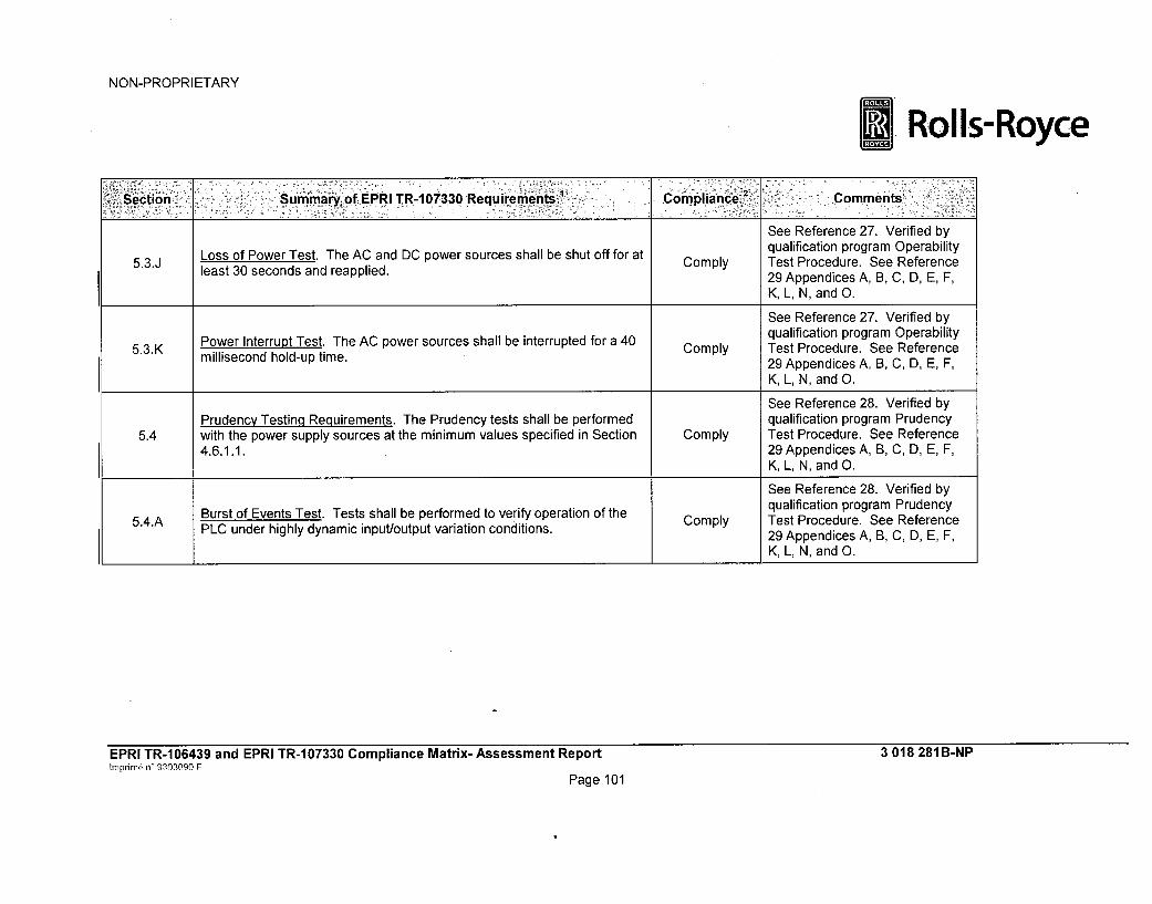
NON-PROPRIETARY
=Rolls-Royce
Section •ummary of,,EPRITR-107330 Requirements Compliance I 'Comments
See Reference 27. Verified byqualification program Operability
5.3.J Loss of Power Test. The AC and DC power sources shall be shut off for at Comply Test Procedure. See Referenceleast 30 seconds and reapplied. 29 Appendices A, B, C, D, E, F,
K, L, N, and 0.
See Reference 27. Verified by
Power Interrupt Test. The AC power sources shall be interrupted for a 40 qualification program Operability5.3.K millisecond hold-up time. Comply Test Procedure. See Reference
29 Appendices A, B, C, D, E, F,K, L, N, and 0.
See Reference 28. Verified byPrudency Testing Requirements. The Prudency tests shall be performed qualification program Prudency
5.4 with the power supply sources at the minimum values specified in Section Comply Test Procedure. See Reference4.6.1.1. 29 Appendices A, B, C, D, E, F,
K, L, N, and 0.
See Reference 28. Verified byBurt of Events Test. Tests shall be performed to verify operation of the C y qualification program Prudency
5.4.A Burstnof highly Test. Tests vari ation ofdthe Comply Test Procedure. See ReferencePLC under highly dynamic input/output variation conditions. 29 Appendices A, B, C, D, E, F,
K, L, N, and 0.
EPRI TR-106439 and EPRI TR-107330 Compliance Matrix- Assessment ReportImprine n' 8303090 F
Page 101
3 018 281 B-NP

NON-PROPRIETARY
*Rolls-Royce
Section ,Summary ofEPRI TR-107330 Requirements' Compliance Comments
The QTS includes fiber-opticcommunication ports forconnection to external safetyrelated or non-safety relatedcommunication devices. Theseconnections inherently provideelectrical isolation between theClass 1E and non-Class 1Ecommunication circuits becausethe fiber optic cables areincapable of transmitting electricalfaults. Further, the fiber opticcables do not include separate
Failure of Serial Port Receiver Test. The receiving device connected to tansmi t a n ceive d at e
5.4.B the main processor serial communication port shall be simulated to fail in Comply Therefore, the test approachvarious modes. PLC response time shall be verified to not degrade described in EPRI TR-107330 is
unacceptably. not applicable. To meet the intent
of EPRI TR-107330, Prudencytesting of the QTS will include atest that demonstrates that theQTS response time is notdegraded due to a simulatedfailure of the QTS fiber opticcommunication connection to theexternal test systemcommunication device(momentary disconnection fromthe non-Class 1 E receivingdevice).
EPRI TR-106439 and EPRI TR-107330 Compliance Matrix- Assessment Reportnprinm6 n' 8303090 F
3 018 281 B-NP
Page 102

NON-PROPRIETARY
*Rolls-Royce
isection •Summary of EPRI TR.-107330 Requirements Compliance 2 - -:. Comments,
As described above, the QTSincludes only fiber opticcommunication line connectionsto external communication
Serial Port Noise Test. The transmit line to the main processor serial devices. These lines are not5.4.C communication port shall be subjected to white noise. PLC response time N/A capable of impressing a low level
shall be verified to not degrade unacceptably. white noise voltage on the QTScommunication port. Therefore,this test is not applicable to thedesign and configuration of theQTS.
This testing is identical to the faultsimulation testing performed aspart of Operability testing
5..D Fault Simulation. For PLC's that include redundancy, failures in redundant Exception (Reference 27). Becauseelements shall be simulated. Operability testing is performed
each time Prudency testing isperformed, this testing will not berepeated during Prudency testing.
EPRI TR-106439 and EPRI TR-107330 Compliance Matrix- Assessment ReportInprim6 n^ 9303090 F
Page 103
3 018 281B-NP

NON-PROPRIETARY
*Rolls-Royce
Section Summary of EPRI T.R-107330 Requirements Compliance 2 - Comments
See References 14, 21, 27, and28. [[
Operability/Prudency Testing Applicability Requirements. As a minimum,Operability and Prudency tests shall be performed:- During acceptance testing: Operability - All, Prudency - All- During environmental testing: Operability - All, Prudency - All at end of
5.5 high temperature/relative humidity Exception- During seismic testing: Operability - All, Prudency - All- After seismic testing: Operability - All, Prudency - None- During EMI/RFI testing: Operability - All except analog-I/O checks,
Prudency - Only burst of events test- After ESD testing: Operability - All, Prudency - None
____________________ _______________________ ]]
EPRI TR-106439 and EPRI TR-107330 Compliance Matrix- Assessment Reportrnprim nW 8303090 F
Page 104
3 018 281 B-NP

NON-PROPRIETARY
*Rolls-Royce
Section Summary of EPRI TR-1,07330 Requirements' Compliance 2 Comments
See Table Section 5.2.A5.6Application Software Objects Acceptance (ASOA) Testinq._Requirementsfor ASOA testing. Based on exception to ASOA testing, Section 5.6requirements are not included in this table.
N/A
6 Qualification Testing and Analysis. Descriptive information. No requirements.
EPRI TR-106439 and EPRI TR-107330 Compliance Matrix- Assessment ReportInprim& n' 8303090 F
Page 105
3 018 281 B-NP
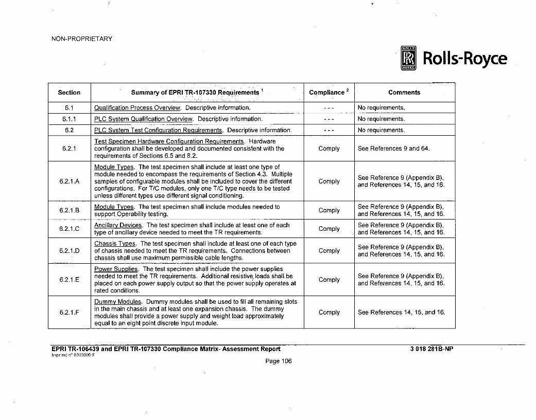
NON-PROPRIETARY
Rolls-Royce
Section Summary of EPRI TR- 07330 Requirements Compliance 2 Comments
6.1 Qualification Process Overview. Descriptive information. --- No requirements.
6.1.1 PLC System Qualification Overview. Descriptive information. --- No requirements.
6.2 PLC System Test Configuration Requirements. Descriptive information. --- No requirements.
Test Specimen Hardware Configuration Requirements. Hardware6.2.1 configuration shall be developed and documented consistent with the Comply See References 9 and 64.
requirements of Sections 6.5 and 8.2.
Module Types. The test specimen shall include at least one type ofmodule needed to encompass the requirements of Section 4.3. Multiple See Reference 9 (Appendix B),
6.2.1 .A samples of configurable modules shall be included to cover the different Comply See Reference 9 (Append B),configurations. For T/C modules, only one T/C type needs to be tested and References 14,15, and 16.unless different types use different signal conditioning.
6.2.1.B Module Types. The test specimen shall include modules needed to Comply See Reference 9 (Appendix B),support Operability testing. and References 14, 15, and 16.
6.2.1.C Ancillary Devices. The test specimen shall include at least one of each Comply See Reference 9 (Appendix B),type of ancillary device needed to meet the TR requirements. and References 14, 15, and 16.
Chassis Types. The test specimen shall include at least one of each type See Reference 9 (Appendix B),6.2.1.D of chassis needed to meet the TR requirements. Connections between Comply and References 14, 15, and 16.
chassis shall use maximum permissible cable lengths.
Power Supplies. The test specimen shall include the power suppliesneeded to meet the TR requirements. Additional resistive loads shall be Comply See Reference 9 (Appendix B),6.2.1 .E placed on each power supply output so that the power supply operates at and References 14, 15, and 16.
rated conditions.
Dummy Modules. Dummy modules shall be used to fill all remaining slots
6.2.1 .F in the main chassis and at least one expansion chassis. The dummy Comply See References 14, 15, and 16.modules shall provide a power supply and weight load approximatelyequal to an eight point discrete input module.
EPRI TR-106439 and EPRI TR-107330 Compliance Matrix- Assessment ReporthInprim& n' 8303090 F
Page 106
3 018 281 B-NP

NON-PROPRIETARY
*Rolls-Royce
Section Summary -of EPRI TR-10330 Requirements Compliance 2 Comments,
Termination Devices. The test specimen shall include at least one of each See Reference 9 (Appendix B),6.2.1.G type of termination device and associated cabling used to provide field Comply and References 14, 15, and 16.
connections.
Redundant Devices. The test specimen shall include any devices needed Comply See Reference 9 (Appendix B),6.2.1.H to implement any redundancy included in the qualification envelope. and References 14, 15, and 16.
Additional Modules. The test specimen shall include any additional See Reference 9 (Appendix B),6.2.1.1 modules needed to support Operability and Prudency testing and to Comply and References 14, 15, and 16.
support module arrangement variations.
6.2.1.1 Test Specimen Hardware Arran-gement Requirements. Descriptive No requirements.information.
6.2.1.1.A Seismic Testing. Hardware shall be arrangement to maximize stress on Comply See References 14, 15, and 16.the chassis and mountings.
6.2.1.1. B Environmental Testing. Modules shall be arranged to simulate maximum Comply See References 14, 15, and 16.expected temperature rise across the chassis.
6.2.2. Test Specimen Application Program (TSAP) Configuration Requirements. No requirements.Descriptive information.
6.2.2.A TSAP Communication Commands. TSAP shall include a serial Comply See Reference 15.communication output sequence.
6.2.2. B TSAP Programming. TSAP shall include program sequences to support Comply See Reference 15.Operability and Prudency testing.
EPRI TR-106439 and EPRI TR-107330 Compliance Matrix- Assessment Reportrnprinm ný 9303090 F
Page 107
3 018 281B-NP

NON-PROPRIETARY
*Rolls-Royce
Section Summar of EPRI TR-1 7330 Requirements Compliance Comments
See Reference 66. On eachcycle, TSAP1 increments by 1 thevalue of counter and sends it toTSAP2 and DAS via networkconnections. Each cycle, TSAP1receives a counter from TSAP2(which has been incremented by8) and sends it for information toDAS via the network. Each cycle,
6.2.2.C TSAP Programming. TSAP shall include a program sequence to change Comply TSAP1 checks the validity of datathe state of an output once each cycle. received from TSAP2 and
elaborates one global invalidityindicator for the networkconnection if there is at least oneinvalid datum. This informationcan be used to diagnose anynetwork problem identifiedthrough NERVIA self-tests (i.e.,the Consistency Blockrefreshment indicator).
6.2.2.D TSAP Programming. TSAP shall include any functions needed to support Comply See Reference 15.6.2.2.D_ redundancy, and fault detection and failover.
EPRI TR-106439 and EPRI TR-107330 Compliance Matrix- Assessment ReporthInprimr n- 8303090 F
Page 108
3 018 281 B-NP

NON-PROPRIETARY
*Rolls-Royce
~Section Summary of'EPRI TR-1 07330Requirements Compliance 2Comments
The SPINLINE 3 system uses acoprocessor that is integral to theUC25+ CPU module. SeeReference 9 (Sections 4.3.3 and4.3.4.7 and Appendix B).
Coprocessor TSAP Requirements. If a coprocessor uses a high-level Operation of SPINLINE 36.2.2.1 language, then it shall have its own TSAP which implements the given N/A coprocessors is invoked
functions. automatically during operationindependent of any applicationsoftware program. Coprocessorprocessing capabilityperformance is inherently testedduring all qualification tests.
See References 14, 15, and 17-Test Support Equipment Requirements. Test equipment to support Comply 28. This requirement is met by a
6.2.3 Acceptance and Operability testing shall be provided. documented qualification plan,
specification, and procedures.
See References 14, 15, and 17 -6.2.3.A Test Support Equipment. Equipment shall include panels for connecting Comply 28. This requirement is met by a
and simulating inputs and outputs. documented qualification plan,
specification, and procedures.
See References 14, 15, and 17-Test Support Equipment. Equipment shall include test and measurement Comply 28. This requirement is met by a
6.2.3.B equipment with required accuracy. documented qualification plan,
specification, and procedures.
See References 14, 15, and 17-Test Support Equipment. Equipment shall include special tools and Comply 28. This requirement is met by a
6.2.3.C devices needed to support testing. documented qualification plan,
specification, and procedures.
EPRI TR-106439 and EPRI TR-107330 Compliance Matrix- Assessment ReportImprim6 n' 8303090 F
Page 109
3 018 281 B-NP

NON-PROPRIETARY
*Rolls-Royce
OSection Summary of, EPRI TR107330 Req irements Complance Comments i-
See References 14 and 18.Intent of IEEE 498 requirementsfor test equipment calibration
6.2.3. D Test Support Equipment. All test equipment shall be controlled per IEEE Comply control met by requiring623D 498. Copy compliance with ANSI/NCSL
Z540-1-1994, "CalibrationLaboratories and Measuring andTest Equipment, GeneralRequirements."
See Reference 18. Verified by
Qualification Tests and Analysis Requirements. All PLC testing shall be qualification program System
6.3 performed on a calibrated system with all user setpoint values adjusted to Comply Setup and Checkout Testdefaut vaues.Procedure. See Reference 29
default values. _Appendices A, B, C, D, E, F, K, L,
N, and 0.See Reference 27. EstablishedAging Requirements. Testing shall include environmental, electrostatic by tefica por tst
6.3.1 discharge (ESD), seismic, EMI/RFI and surge withstand testing. Comply by the qualification program test
Environmental testing shall be performed first. Appendices D, F, G, H and I.
EPRI TR-1 06439 and EPRI TR-1 07330 Compliance Matrix- Assessment ReportInprim6 W 8303090 F
Page 110
3 018 281 B-NP

NON-PROPRIETARY
*Rolls-Royce
Section Summary of EPRI TR1 07330 Requirements Compliance 2 - Comments
See References 22 and 29.Established by the qualificationprogram EMI/RFI Test Procedure.
Comply Additional testing from 1 - 8 GHzwas performed in a second round
EMI/RFI Test Requirements. EMI/RFI testing to be performed as of qualification testing, as6.3.2 described in Section 4.3.7. Susceptibility tests to be performed at 25%, recommended by Regulatory
50% and 75% of specified levels in addition to the specified levels. Guide 1.180, Revision 1.
Exception
EPRI TR-1 06439 and EPRI TR-1 07330 Compliance Matrix- Assessment ReportIrnprim6 n' 8303090 F
Page 111
3 018 281B-NP

NON-PROPRIETARY
*Rolls-Royce
Section Summary of EPRI TR-107330 Requirements Compliance 2 Comments
See References 21 and 29. QTSwas mounted in one openmounting frame. [[
EMI/RFI Mounting Requirements. Test specimen shall be mounted on a6.3.2.1 non-metallic surface six feet above floor with no secondary enclosure. Exception
PLC shall be grounded per manufacturer's recommendations.
Grounding of the QTS and testsystem is in accordance with themanufacturer recommendations(Reference 96). This groundingconfiguration met MIL-STD-461Eand IEC 61000 requirements.
EPRI TR-106439 and EPRI TR-107330 Compliance Matrix- Assessment ReportInprim6 n' 8303090 F
Page 112
3 018 281 B-NP

NON-PROPRIETARY
*Rolls-Royce
:-• :Section Summary of EPRI TR-107330 Requirements 1 Compliance.2 comments
Environmental Testincq Requirements. Testing shall be performed usingthe temperature and relative humidity profile given in TR Figure 4-4.Margin shall be applied to maximum and minimum specified temperatures
6.3.3 and humidities. Power sources shall be set to maximize heat dissipation. Comply See References 14, 20, and 29.PLC shall be energized with TSAP operating. One-half of all discrete andrelay outputs shall be on and energized to rated current. All analogoutputs shall be set to one-half to two-thirds full scale output.
Environmental Test Mounting Requirements. PLC shall be mounted on a6.3.3.1 simple structure. Air temperature at bottom of chassis shall be monitored. Comply See References 14, 20, and 29.
No additional cooling fans shall be included.
Seismic Test Requirements. PLC shall be vibration aged using five OBEswith the RRS as shown in TR Figure 4-5 followed by an SSE with the RRS See References 14,15, 21, and
6.3.4 shown in TR Figure 4-5. Testing shall conform to IEEE 344. Tri-axial, Comply 29.random, multi-frequency tests shall be used. Repairs during testing shallconform to IEEE 344.
Seismic Test Mounting Requirements. Test specimen shall be mounted
6.3.4.1 per manufacturer's recommendations. Mounting structure shall have no Comply See References 14, 15, 21, andresonances below 100 Hz. Most susceptible mounting configuration shall 29.be tested. All mounting screws shall be torqued to known values.
Seismic Test Measurement Requirements. Relay contacts shall bemonitored for chatter. One half of the relays shall be energized and onehalf de-energized. One quarter of the relays shall transition from ON to
6.3.4.2 OFF and one quarter from OFF to ON during the tests. The PLC shall be Comply See References 14, 15, 21, andpowered with the TSAP operating. One half of the digital outputs shall be 29.ON and loaded to their rated current. Power sources shall be at lowervoltage and frequency limits. One or more response accelerometers shallbe mounted on each chassis.
6.3.4.3 Seismic Test Performance Requirements. Seismic test shall include a Comply See References 14, 15, 21, andresonance search, five OBEs, one SSE and an Operability test. 29.
EPRI TR-106439 and EPRI TR-107330 Compliance Matrix- Assessment ReportImprim6 n' 8303090 F
Page 113
3 018 281B-NP

NON-PROPRIETARY
*Rolls-Royce
Section Summary of EPRI TR-1 07330 Requirements I Compliance 2 Comments
See References 140 and 141.Seismic Test Spectrum Analysis Requirements. The test response NTS performed an analysis at
6.3.4.4 spectrum from the control and specimen response accelerometers shall be Comply 1/2, 1,2, 3, and 5% damping onreported at 1/2, 1, 2, 3 and 5% damping. the control accelerometers for at
least one OBE and the SSE runs.
See Reference 25. Surge
6.3.5 Surge Withstand Capability Testing. Surge testing shall be conducted per Comply withstand capability meets IECSection 4.6.2 and IEEE C62.45. 61000-4-5 and IEC 61000-4-12.
See Reference 29 Appendix H.
See Reference 25. Surgewithstand capability meets IEC61000-4-5 and IEC 61000-4-12.QTS was mounted in one openmounting frame. [[
Surge Withstand Test Mounting Requirements. Test specimen shall be6.3.5.1 mounted on a non-metallic surface six feet above floor with no secondary Exception
enclosure. PLC shall be grounded per manufacturer's recommendations.
]] SeeReference 29 Appendix H.
EPRI TR- 06439 and EPRI TR-1 07330 Compliance Matrix- Assessment ReportImprime n' 8303090 F
Page 114
3 018 281 B-NP

NON-PROPRIETARY
cRolls-Royce
Section Summary of EPRI TR-107330 Requirements Compliance 2 Comments
See Reference 26. Class 1 E toNon-1 E isolation capability meetsIEEE 384-1981. [[
Class 1E to Non-lE Isolation Testinq. Test specimen shall be mounted on6.3.6 a non-metallic surface six feet above floor with no secondary enclosure. Exception
PLC shall be grounded per manufacturer's recommendations.
]] SeeReference 29 Appendix J.
6.4 Other Tests and Analysis. (section heading) --- No requirements.See Reference 9 Section 5.2 andReferences 30 - 41. Thehardware failure modes andeffects were analyzed for eachSPINLINE 3 hardware module.The hardware failure modes and
6.4.1 FMEA. An FMEA analysis of the PLC shall be performed. Partially effects are used as input to theComply project-specific evaluation of a
complete systemSee Reference 10 entries forItems 2.8 and 2.15 for thetreatment of project-specificactions.
See Reference 23. Verified by6.4.2 Electrostatic Discharf e (ESD) Testinq Requirements. ESD testing of the Comply ESD qualification testing. SeePLC shall be performed per EPRI TR-102323. Reference 29 Appendix I.
EPRI TR-106439 and EPRI TR-107330 Compliance Matrix- Assessment ReportIprinm6 n' 8303090 F
Page 115
3 018 281B-NP

NON-PROPRIETARY
* Rolls-Royce
Section Summary of EPRI TR-107330 Requirements Compliance 2 Comments
Power Quality Tolerance Requirements. Power quality tolerance testingshall be performed during acceptance testing, at the end of the elevated See References 14, 17, 20, 21,
6.4.3 temperature test while still at high temperature and following seismic tests. Comply 27, and 29 Appendices A, B, C,The same AC source shall be connected to redundant power supplies D, E, F, K, L, N, and 0.during testing.
Requirements for Compliance to Specifications. Test instrumentation6.4.4 measurement accuracy shall be considered. Compliance to specifications Comply See References 14, 18, and 29.
shall be considered for each module or grouping of modules.
Environmental Test Compliance. Environmental Operability test results Comply See References 14, 18, 20, 27,6.4.4.A shall be evaluated for compliance to specifications. and 29 Appendix D.
See References 14, 18, 21, 27,and 29 Appendices E and N.Seismic test deficiencies were
Seismic Test Compliance. The seismic levels achieved during testing Partially resolved by a second round of6.4.4.B shall be used as the seismic withstand response spectrum. Comply qualification testing. Limitationson the qualification envelope aredescribed in Reference 29(Appendix E).
See References 14, 26 and 29
6.4.4.C Class 1 E to Non-i E Test Compliance. Test levels shall be checked for Comply Appendix J. Class 1 E to Non-i Ecompliance to Section 4.6.4 specifications. isolation capability meets IEEE
384-1981.
See References 25 and 29
6.4.4.D Surge Withstand Test Compliance. Test levels shall be checked for Partially Appendix H. Surge withstandcompliance to Section 4.6.2 specifications. Comply capability meets IEC 61000-4-5
and IEC 61000-4-12.
EPRI TR-106439 and EPRI TR-107330 Compliance Matrix- Assessment ReportImprime n' 8303090 F
Page 116
3 018 281B-NP

NON-PROPRIETARY
*Rolls-Royce
Sectioný Summary of EPRI TR-107330 Requirements q Compliance 2 Comme nts
See References 22, 24, and 29Appendices F, G and 0. Verifiedby EMC qualification testing.
EMI/RFI Test Compliance. PLC performance shall be checked for Additional testing from 1 - 8 GHz6.4.4.E compliance to Section 4.3.7 specifications. Comply was performed in a second round
of qualification testing, asrecommended by RegulatoryGuide 1.180, Revision 1.
See References 14, 17, 20, 21,
Power Quality Test Compliance. Results shall be evaluated for 27, and 29 Appendices A, B, C,6.4.4.F compliance to Sections 4.6.1 and 4.2.3.7 specifications. Comply D, E, F, K, L, N, and 0. Verified
by Operability qualificationtesting.
6.4.4.G ASOA Test Compliance. Results shall be evaluated for compliance to N/A See Table Section 5.2.A.Section 5.6 requirements.
See Reference 62.Global Quality Assurance AuditReport dated February 3, 2009.
Quality Assurance Program Compliance. Results of audits of Audit Date: January 19 - 23,6.4.4.H manufacturer's QA Program shall be checked for compliance to Section 7 Comply 2009.
requirements. Products/Scope: Design andManufacture of SafetyInstrumentation and ControlsSystems.
6.4.5 Human Factors. Descriptive Information. No requirements.
EPRI TR-106439 and EPRI TR-107330 Compliance Matrix- Assessment ReportImprim6 n' 8303090 F
Page 117
3 018 281B-NP

NON-PROPRIETARY
*Rolls-Royce
Section Summary of EPRITR-I•7330 Requirements' Compliance2 Comments
See References 9 (Section 1.4and Table 3.2-1), 14, and 64.
Quality Assurance Measures Applied to Qualification Testing. Test This requirement is met by aprogram TSAP development, hardware procurement, test specimen chain documented Qualification
6.5 fComply Program Quality Assurance Planof custody, and tests and data analysis shall meet the requirements of that references applicable10 CFR Part 50, Appendix B. 10 CFR Part 50, Appendix B
Quality Assurance Programprocedures.
7 Quality Assurance. Descriptive information. --- No requirements.
7.1 QA Overview. Descriptive information. - - - No requirements.
7.2 10 CFR Part 50, Appendix B Requirements for Safety-Related Systems. --- No requirements.Descriptive information.
See References 9 (Section 1.4and Table 3.2-1) and 14. Thisrequirement is met by a
10 CFR Part 50, Applicability. Regulations apply to all qualification documented Qualification7.2.A activit Comply Program Quality Assurance Planactivities. that references applicable
10 CFR Part 50, Appendix BQuality Assurance Programprocedures.
See Reference 9 (Section 1.4 andTable 3.2-1). This requirement ismet by a documented
7.2.B 10 CFR Part 50, Applicability. Regulations apply to application specific Comply Qualification Program Qualityactivities. Assurance Plan that references
applicable 10 CFR Part 50,Appendix B Quality AssuranceProgram procedures.
EPRI TR-1 06439 and EPRI TR-1 07330 Compliance Matrix- Assessment ReporthInprin) n' 8303090 F
Page 118
3 018 281B-NP

NON-PROPRIETARY
1Rolls-Royce
-Section -Summary of EPRI TR-1 07330 Requirements Compliance2 Comments
See Reference 9 (Section 1.4). Ifnecessary, this requirement ismet by a documented
7.2.C 10 CFR Part 50, Applicability. Regulations apply to PLC dedication Comply Qualification Program Qualityactivities. Assurance Plan that references
applicable 10 CFR Part 50,Appendix B Quality AssuranceProgram procedures.
See References 9 (Sections 1and 6.3 and Table 3.10-2) and13. Rolls-Royce concluded that
7.2.D 10 CFR Part 50 Compliance. Quality processes other than 10 CFR Part Comply the SPINLINE 3 platform software50 shall be shown to be commensurate with 10 CFR Part 50. life cycle process (based on IEC
880) achieves equivalent resultsto those that would be attainedusing BTP 7-14.
10 CFR Part 50 Compliance. Qualifier shall perform audits to confirm that Comply See Reference 9 (Table 3.2-17.2.E manufacturer's quality process has been applied to the PLC product. Item XVIII -Audits).
Rolls-Royce will manufacture the10 CFR Part 50 Compliance. Audits performed against manufacturer SPINLINE 3 systems under a
7.2.F programs other than 10 CFR Part 50 shall demonstrate that the program N/A 10 CFR Part 50, Appendix Bprocess is commensurate with 10 CFR Part 50. program.
See References 9 (Sections 1and 6.3 and Table 3.10-2) and13. Rolls-Royce concluded that
7.2.G V&V Program Evaluation. Qualifier shall evaluate the manufacturer's V&V Comply the SPINLINE 3 platform softwareprogram to the criteria in Section 7.4. life cycle process (based on IEC
880) achieves equivalent resultsto those that would be attainedusing BTP 7-14.
EPRI TR-1 06439 and EPRI TR-1 07330 Compliance Matrix- Assessment ReportImprim f ný 8303090 F
Page 119
3 018 281B-NP

NON-PROPRIETARY
*Rolls-Royce
Section. -Summary of EPRI TR-1 07330 Requirements Compliance2 Comments
7.2.H Qualification Test Witnessing. The qualifier shall have the right to witness N/A Rolls-Royce is the manufacturerqualification tests. and qualifier.
10 CFR Part 21 Compliance Requirements. Section lists 10 CFR Part 21 Comply See References 9 (Sections 1.4compliance requirements of a utility which applies the PLC in a-safety- and 4.1.2) and 13. Thisrelated application. PLC manufacturer shall support problem reporting and requirement is met by atracking. documented Qualification
7.3 Program Quality Assurance Planthat references applicable10 CFR Part 50, Appendix BQuality Assurance Programprocedures.
Verification and Validation Requirements. Qualifier shall evaluate the Comply See References 9 (Sections 1,manufacturer's V&V process for software, firmware and software tools 6.3, and 6.4 and Tables 3.8.1,against IEEE 7-4.3.2 and IEEE 1012. The qualifier shall confirm the 3.8.9 through 3.8.11), 10, and 13.following basic requirements are met: a) there is a V&V Plan for the PLC Rolls-Royce concluded that theproduct, b) software development shall be done in accordance with a life SPINLINE 3 platform software life
7.4 cycle approach (see IEEE Std 1074-1995), and c) the software cycle process (based on IEC 880)requirements document shall be reviewable. achieves equivalent results to
those that would be attainedIf the manufacturer V&V processes do not meet requirements applicable to N/A using BTP 7-14.Nuclear Power Plants, then compensatory measures shall beimplemented.
7.5 Manufacturer Qualification Maintenance Throughout Product Life Cycle. No requirements.(section heading) N q m
7.5.1 Overview of Manufacturer Qualification Maintenance Throughout Product No requirements.Life Cycle. Descriptive information.
EPRI TR-106439 and EPRI TR-107330 Compliance Matrix- Assessment ReportInprimi6 ný 8303090 F
Page 120
3 018 281B-NP

NON-PROPRIETARY
*i Rolls-Royce,• ~t~n!i:• •::•!bj•:i!•:!L!Summaryof EPRI TR-107330: Requirements:••::::•!:,, oti-:poilance!: CGommernt
Requirements for Manufacturer Qualification Maintenance Throughout Rolls-Royce is the manufacturerProduct Life Cycle. The qualifier shall obtain documentation confirming and qualifier. The development
7.5.2 that the PLC manufacturer will ensure upward compatibility, maintain rigor Comply and qualification processes to beof processes, commit to at least five year support for the qualified PLC used in the future are describedconfiguration, and commit to six months notice before withdrawing product in Reference 9 (Sections 1, 5,support. and 6).
LifeCyce fr Tols equremnt. LC anuactrer hal enureRolls-Royce is the manufacturerLieCceSupport fo ol eurmn.PCmnfcue hl nueand qualifier. The development
753 continued access to the same versions of application software Comply tools to be used in the future aredevelopment tools, or capability to reconstruct functionality with using described in Reference 9 (Sectionrevised tools. 4.4.4).
7.6 Compensatory Quality Activities for Leqacy Software. (section heading) - -- No requirements.
7.6.1 Overview of Compensatory Quality Activities for Legacy Software. - - - No requirements.Descriptive information.
EPRI TR-1 06439 and EPRI TR-1 07330 Compliance Matrix- Assessment ReportImprir•no 8303090 F
Page 121
3 018 281B-NP

NON-PROPRIETARY
I Rolls-Royce2
~Sectio~n Summary of EPRI TR-107330 Requirements- Compliance Comet
Rolls-Royce did not useSPINLINE operating experienceto compensate for shortcomingsin legacy software. Thedevelopment process for theSPINLINE 3 system was found tobe both robust and consistentwith applicable US regulatoryguidance. The SPINLINE 3software development processhad a rigorous verification andvalidation program to confirm
Requirements for Compensatory Quality Activities for Legacy Software. conformance to requirements. InThe qualifier may compensate for shortcomings in legacy software by has considerable deployment
7.6.2 evaluating documented operating experience in applications similar to N/A experience in nuclear powernuclear safety related applications, and by performing tests of legacy plants and has operated reliably
software to confirm conformance to requirements. The manufacturer shallplace legacy software under configuration control once baselined, in systems and environments
comparable to those in U.S.
nuclear power plants. SeeReference 9 (Sections 2 and 6.1)described the operationalexperience that supplements thesoftware development processesdescribed in Reference 9(Sections 6.2 and 6.4).Reference 9 (Sections 6.2.6 and6.4.3 and Tables 3.8.6 through3.8.8) describe the SPINLINE 3configuration managementsystem.
7.7 Configuration Management. (section heading) No requirements.
EPRI TR-106439 and EPRI TR-107330 Compliance Matrix- Assessment Reportnprinp6 nW 8303090 F
Page 122
3 018 281 B-NP

NON-PROPRIETARY
* Rolls-Royce
Section Summary of EPRI TR-107330 Requirements Compliance 2 Comments -
7.7.1 Configuration Management Overview. Descriptive information. --- No requirements.
See Reference 9 (Table 3.2-1Items III - Design Control, VII -
Hardware Configuration Management Requirements. The scope shall Control of Purchased Materials,7.7.2 include revisions to module design, module component configuration, Comply Equipment and Services, VIII -
compatibility of revised modules with existing hardware, and manufacturer Identification and Control ofdocumentation. Materials, Parts and Components,
and IX - Control of SpecialProcesses).
Hardware Configuration Management Review. Utility (and Qualifier) shall See Reference 9 (Table 3.2-1
7.7.2.A evaluate the manufacturer configuration management process for design Comply - Control of Purchased Materials,revisions to NQA-I. Equipment and Services).
See Reference 9 (Table 3.2-1Items III - Design Control, VII -
Hardware Configuration Management Review. Utility (and Qualifier) shall Control of Purchased Materials,
7.7.2.B evaluate the manufacturer configuration management process for methods Comply Equipment and Services, VIII -of identification of each constituent component within the PLC modules to Identification and Control ofNQA-1. Materials, Parts and Components,
and IX - Control of SpecialProcesses).
See Reference 9 (Table 3.2-1Items V - Instructions, Procedures
Hardware Configuration Management Review. Utility (and Qualifier) shall and Drawings, VI - Document7.7.2.C evaluate the manufacturer configuration management process for methods Comply Control, VII - Control of
of document control to NQA-1. Purchased Materials, Equipmentand Services, and XVII - QualityAssurance Records).
EPRI TR-106439 and EPRI TR-107330 Compliance Matrix- Assessment ReportImprim6 n' 8303090 F
3 018 281 B-NP
Page 123

NON-PROPRIETARY
* Rolls-Royce
Section Summary of EPRI TR-1 07330.Requirements Compliance 2Comments
See Reference 9 (Sections 6.2.6and 6.4.3 and Tables 3.8.6
Software Configuration Management Requirements. The scope of through 3.8.8) for a description of
software configuration management includes creation and revision of Comply management system.7.7.3 firmware, runtime software libraries, software engineering tools, and See Refenc 10etes I
documentation. See Reference 10 entries for Item1.10 for the SPINLINE 3
configuration managementimplementation documents.
See Reference 9 (Sections 6.2.6and 6.4.3 and Tables 3.8.6through 3.8.8) for a description of
Software Configuration Management Review. Utility (and Qualifier) shall the SPINLINE 3 configuration
7.7.3.A evaluate the manufacturer software configuration management process for Cm e syste m.definition of organization and responsibilities to Reg. Guide 1.169, Section Comply management system.
C. See Reference 10 entries for Item1.10 for the SPINLINE 3configuration managementimplementation documents.
See Reference 9 (Sections 6.2.6and 6.4.3 and Tables 3.8.6through 3.8.8) for a description of
Software Configuration Management Review. Utility (and Qualifier) shall the SPINLINE 3 configuration
7.7.3.B evaluate the manufacturer software configuration management process for Cm e syste m.methods of configuration identification, control, status and audits to Reg. Comply management system.
Guide 1.169, Section C. See Reference 10 entries for Item1. 10 for the SPINLINE 3
configuration managementimplementation documents.
EPRI TR-106439 and EPRI TR-107330 Compliance Matrix- Assessment Reportimnprim6 ný 8303090 F
Page 124
3 018 281 B-NP

NON-PROPRIETARY
* Rolls-Royce
Section -Summary of EPRI TR- 07330XRequirements Compliance 2 Comments
See Reference 9 (Sections 6.2.6and 6.4.3 and Tables 3.8.6through 3.8.8) for a description of
Software Configuration Management Review. Utility (and Qualifier) shall the SPINLINE 3 configuration
7.7.3.C evaluate the manufacturer configuration management process to ensure Comply management system.sub-tier suppliers maintain comparable levels of configuration See Refenc 10ete s I
management per Reg. Guide 1.169, Section C. See Reference 10 entries for Item1. 10 for the SPINLINE 3configuration managementimplementation documents.
This requirement is met by aProblem Reporting/Tracking Requirements. PLC manufacturer shall documented Quality Assurancemaintain a problem reporting and tracking system that includes Plan that references applicableclassification of problems, description of problems, identification of 10 CFR Part 50, Appendix B
7.8 affected hardware, type of application, description of configuration, name Comply Quality Assurance Programof reporting site and means to contact site, type of site, and cumulative procedures. See References 9operating time of PLC when problem occurred. Manufacturer shall provide (Table 3.2-1 Item XV -a mechanism for making this information available to all nuclear utility Nonconforming Materials, Parts ofusers. Components and Item XVI -
Corrective Action) and 61.
8 Documentation. Descriptive information. --- No requirements.
8.1 Equipment General Overview Document Requirements. Descriptive --- No requirements.information.
8.1.A Manufacturer Documentation. Documentation shall include a description Comply See Reference 9 (Section 4 andof the PLC. Appendix B).
8.1.B Manufacturer Documentation. Documentation shall include a description Comply See Reference 9 (Section 4 andof the chassis interconnections. Appendix B).
8.1.C Manufacturer Documentation. Documentation shall include a module Comply See Reference 9 (Section 4 andoverview and selection guide. Appendix B).
EPRI TR-106439 and EPRI TR-107330 Compliance Matrix- Assessment Reporthnprim6 n' 8303090 F
3 018 281B-NP
Page 125

NON-PROPRIETARY
*Rolls-Royce
Section Summary of EPRI TR-107330 Requirements Compliance 2 Comments
8.1.D Manufacturer Documentation. Documentation shall include a description See Reference 9 (Section 4 andof the overall I/O capacity and processing speeds. Comply Appendix B).
Manufacturer Documentation. Documentation shall include installation8.1.E information. Comply See References 75 and 96.
Manufacturer Documentation. Documentation shall include handling and Comply See Reference 62 and 78.storage requirements.
8.1.G Manufacturer Documentation. Documentation shall include a description Comply See Reference 9 (Section 4).of the self-diagnostics and redundancy features.
8.2 Equipment General Specifications Requirements. Manufacturer Comply See Reference 9.documentation shall provide general specifications for the PLC.
8.3 iuOperator's Manual Requirements. Manufacturer documentation shall Comply See Reference 9 (Section 4).include information on operation of the PLC.
8.4 Programmer's Manual Requirements. Manufacturer shall provide detailed Comply See References 81, 82, 83, andinformation on the use of the functions available in the PLC processors. 84.
Programmer's Manual Requirements. Manual shall include a summary See References 81, 82, 83, and8.4.A and brief description of available functions. Comply 84.
8.4.1B Programmer's Manual Requirements. Manual shall include a detailed comply See References 81, 82, 83, anddescription of each function. S Rre1 ,a84.
8.4.C Programmer's Manual Requirements. Manual shall include examples of Comply See References 81, 82, 83, andcomplex functions. 84.
8.4.D Programmer's Manual Requirements. Manual shall include limitations on See References 81, 82, 83, anduse of functions. Comply 84.
8.4.E Programmer's Manual Requirements. Manual shall include methods for See References 81,82, 83, andresource management. 84.
Programmer's Manual Requirements. Manual shall include a user manual See References 81, 82, 83, and8.4.F for programming and debugging tools, and for any programming terminal. Comply 84.
EPRI TR-106439 and EPRI TR-107330 Compliance Matrix- Assessment Reporthnprini n' 8303090 F
Page 126
3 018 281 B-NP

NON-PROPRIETARY
* Rolls-Royce
Section summary of EPRI TR-i 07330 Requirements, Cmin Comments
See References 53 and 60. The
8.4.G Programmer's Manual Requirements. Manual shall include detailed Comply SPINLINE 3 programming toolsinformation for creating user defined functions. are not intended for use by the
end user.
8.4.H Programmer's Manual Requirements. Manual shall include a detailed Comply See References 81 and 82.description of operation of conditional statements.
The SPINLINE 3 system8.4.1 Proqrammer's Manual Requirements. Manual shall include a description N/A application software does not
of limitations of PID and lead/lag functions. include specific PID or lead/lag
functions.
8.4. Programmer's Manual Requirements. Manual shall include a description Comply See References 83 and 84.of interaction between main processor and I/O modules.
Programmer's Manual Requirements. Manual shall include a detailed8.4.K description of interaction between the application program and redundancy Comply See References 83 and 84.
features.
8.4.L Programmer's Manual Requirements. Manual shall include any software Comply See References 81, 82, 83, andbuild procedures and software tools. 84.
8.4.M Programmer's Manual Requirements. Manual shall include a description Comply See References 83 and 84.of the operation of the executive.
8.4. N Programmer's Manual Requirements. Manual shall include a description Comply See References 83 and 84.of data, data base and configuration management.
8.4.0 Programmer's Manual Requirements. Manual shall include a description Comply See References 83 and 84.of operation and use of self-diagnostics.
EPRI TR-1 06439 and EPRI TR-1 07330 Compliance Matrix- Assessment Reportlrnprim6 n' 8303090 F
Page 127
3 018 281 B-NP
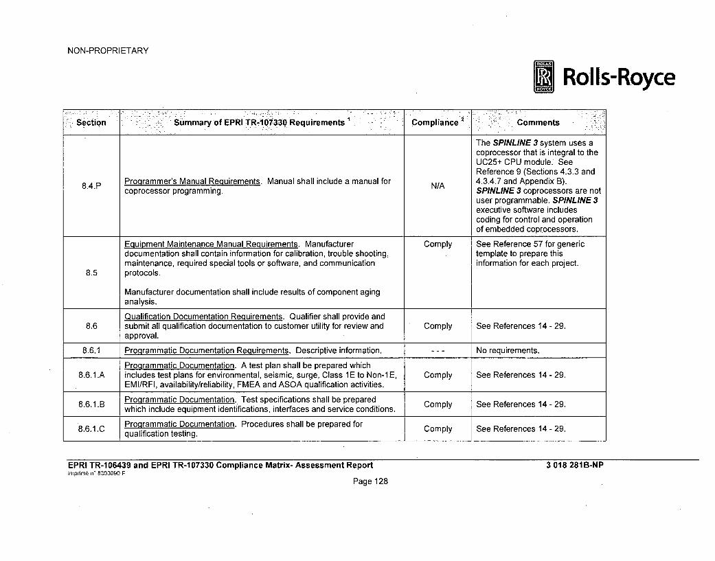
NON-PROPRIETARY
LRolls-Royce
Section Summaryof EPRITRA-17330ORequirements Compliance . Comments
The SPINLINE 3 system uses acoprocessor that is integral to theUC25+ CPU module. SeeReference 9 (Sections 4.3.3 and
8.4.P Programmer's Manual Requirements. Manual shall include a manual for N/A 4.3.4.7 and Appendix B).coprocessor programming. SPINLINE 3 coprocessors are not
user programmable. SPINLINE 3executive software includescoding for control and operationof embedded coprocessors.
Equipment Maintenance Manual Requirements. Manufacturer Comply See Reference 57 for genericdocumentation shall contain information for calibration, trouble shooting, template to prepare thismaintenance, required special tools or software, and communication information for each project.
8.5 protocols.
Manufacturer documentation shall include results of component aginganalysis.
Qualification Documentation Requirements. Qualifier shall provide and8.6 submit all qualification documentation to customer utility for review and Comply See References 14 - 29.
approval.
8.6.1 Programmatic Documentation Requirements. Descriptive information. --- No requirements.
Programmatic Documentation. A test plan shall be prepared which8.6.1 .A includes test plans for environmental, seismic, surge, Class 1 E to Non-1 E, Comply See References 14 - 29.
EMI/RFI, availability/reliability, FMEA and ASOA qualification activities.
8.6. 1. B Programmatic Documentation. Test specifications shall be prepared Comply See References 14 - 29.which include equipment identifications, interfaces and service conditions.
8.6.1.C Programmatic Documentation. Procedures shall be prepared for Comply See References 14 - 29.qualification testing.
EPRI TR-106439 and EPRI TR-107330 Compliance Matrix- Assessment ReportInprime n' 8303090 F
Page 128
3 018 281 B-NP

NON-PROPRIETARY
*Rolls-Royce
ýýSection Summary of EPRI TR1 07330 Requirements Compliance 2 Comments
See Reference 29.8.6.1.D Programmatic Documentation. Test reports shall be prepared for each Comply (To be updated after completion
qualification test performed. of second round of qualificationtesting.)
This requirement is met by
Programmatic Documentation. Reports on audits performed on the performing audits in accordance8.6.P1.aE hanumetation shall be prermded. Comply with the Rolls-Royce Qualitymanufacturer all bprepared. Assurance Manual (Reference
61).
Programmatic Documentation. Reports on design evaluations shall be Comply See References 151 - 154 for8.6.1.F prepared. examples.
8.6.2 Technical Items and Acceptance Criteria Documentation Requirements. --- No requirements.Descriptive information.
Technical Items Documentation. Documentation shall include test See References 14, 15, 16, and8.6.2.A specimen requirements. Comply 29.
TenSee Reference 70 for QTS End of8.6.2.B echnical Items Documentation. Documentation shall include test N/A Manufacturing Report (certificate
specimen purchasing records. of conformance).
Technical Items Documentation. Documentation shall include TSAP See Reference 71 for list of QTS8.6.2.C development documentation. Comply TSAP documents.
8.6.2. D Technical Items Documentation. See Sections 8.8, 8.9, 8.10, 8.12 and No requirements.
8.13.
8.6.2.E Technical Items Documentation. See Section 8.14. --- No requirements.
See Reference 29.
8.6.3 Application Guide Documentation Requirements. A qualification summary Comply (To be updated after completiondocument shall be provided. of second round of qualification
testing.)
EPRI TR-1 06439 and EPRI TR-1 07330 Compliance Matrix- Assessment Reportimprin6 n' 8303090 F
Page 129
3 018 281 B-NP

NON-PROPRIETARY
Rolls-Royce
Section Summary of EPRI TR-1 07330 Requirements Compliance 2 Comments
8.6.3.A Application Guide. Guide shall include results of environmental Operability Comply See Reference 29.testing to support each specific safety related application.See Reference 29.
Application Guide. Guide shall include results of seismic testing including
8.6.3.B seismic withstand capability for all damping values used in test data Comply (To be updated after completionanalysis. of second round of qualification
testing.)
Application Guide. Guide shall include results of Class 1 E to Non-1 E Comply See Reference 29.8.6.3.C isolation testing.
8.6.3.D Application Guide. Guide shall include results of surge withstand testing. Comply See Reference 29.
See Reference 29.
8.6.3.E Application Guide. Guide shall include results of EMI/RFI testing. Comply (To be updated after completionof second round of qualificationtesting.)
8.6.3.F Application Guide. Guide shall include results of power quality testing. Comply See Reference 29.
8.6.3.G Application Guide. Guide shall describe any combination of software N/A No software objects or specialobjects or special purpose objects created to support testing. purpose objects used in testing.
8.6.3.H Application Guide. Guide shall include a description of the as-tested PLC Comply See Reference 29.configuration.
8.6.3.1 Application Guide. Guide shall include a description of the executive Comply See References 16 and 89.software and software tools revision levels included in qualification.
8.6.3.J Application Guide. Guide shall include a description of the as-tested PLC Comply See Reference 29.8.6.3.J_ configuration.
EPRI TR-1 06439 and EPRI TR-1 07330 Compliance Matrix- Assessment Reporthnprinm• n' 8303090 F
Page 130
3 018 281 B-NP

NON-PROPRIETARY
*Rolls-Royce
•Section Summary of EPRI TR-1 07330 Requirements Compliance -Comments
See Reference 9 Section 5.2 andReferences 30 - 41. Thepredicted hardware failure ratesdemonstrate that the reliabilityrequirements for project-specificsystems can be met with thetypical redundant architecturesused for nuclear power plantsafety systems, as demonstratedby the operating experience withSPINLINE 3 (see Reference 9
8.6.3.K Application Guide. Guide shall include a summary of the FMEA and Comply Section 2.2.). The hardwareavailability analysis. failure modes and effects were
analyzed for each SPINLINE 3hardware module. The hardwarefailure modes and effects areused as input to the project-specific evaluation of a completesystem.See Reference 10 entries forItems 2.8 and 2.15 for thetreatment of project-specificactions.
See Reference 9 Section 5.2.2and Reference 42.
8.6.3. L Application Guide. Guide shall include the setpoint analysis support Comply See Reference 10 entries fordocument. Items 1.21 and 2.16 for the
treatment of project-specificactions.
8.6.3.M Application Guide. Guide shall include information from manufacturer Comply See References 88 and 164.audits and surveys applicable to future purchasing.
EPRI TR-106439 and EPRI TR-107330 Compliance Matrix- Assessment ReportIrnprim6 n^ 8303090 F
Page 131
3 018 281B-NP

NON-PROPRIETARY
Rolls-Royce
Section Summary.of EPRI TR-1 07330 Requirements Compliance 2 " Comments
8.6.3.N Application Guide. Guide shall include a description of the redundancy Comply See Reference 29.features include in qualification.
8.6.3.0 Application Guide. Guide shall include a description of external devices Comply See Reference 29.included in qualification.
8.6.3.P Application Guide. Guide shall include a description of the PLC Comply See Table Section 7.7 above.configuration management methods.
See Reference 9 Section 5.2 andReferences 30 - 41 demonstratethat the predicted reliability forSPINLINE 3 modules are greaterthan the typical nuclear plantsurveillance intervals used todetect failures,Reference 57 contains thegeneric plan to develop project-specific preventive maintenance
8.6.3.Q Application Guide. Guide shall include a summary of the component aging Comply recommendations for anyanalysis. components with limited life (e.g.,
batteries, air filters, or electrolyticcapacitors).Regulatory Position C.1 of NRCRegulatory Guide 1.209 does notrequire the age conditioning inIEEE Std. 323-2003 Section6.2.1.2 to be applicable becauseof the absence of significantaging mechanisms onmicroprocessor-based modules.
EPRI TR-106439 and EPRI TR-107330 Compliance Matrix- Assessment ReportInprim6 W 8303090 F
Page 132
3 018 281 B-NP

NON-PROPRIETARY
*Rolls-Royce
Section Summary of EPRI TR1 07330,Requirements Cqmpliance Comments
See Reference 29.
8.6.3.R Application Guide. Guide shall include a description of seismic mounting Comply (To be updated after completionmethods. of second round of qualification
testing.)
See Reference 29.
8.6.3.S Application Guide. Guide shall include a description of qualification Comply (To be updated after completionenvelopes for specific modules if different from the overall envelope. of second round of qualification
testing.)
Application Guide. Guide shall include a description of any application8.6.3.T hardware or software features that are assumed in order to meet Comply See Reference 29.
qualification requirements.
EPRI TR-106439 and EPRI TR-107330 Compliance Matrix- Assessment Reporthrnprini n' 8303090 F
Page 133
3 018 281B-NP

NON-PROPRIETARY
*Rolls-Royce
S::ectiobn=, ' - "Summary of EPRiVTR-107330 Requirements Compliance . Comments
See Reference 9 Section 5.2 andReferences 30 -41. Thepredicted hardware failure ratesdemonstrate that the reliabilityrequirements for project-specificsystems can be met with thetypical redundant architecturesused for nuclear power plantsafety systems, as demonstratedby the operating experience withSPINLINE 3 (see Reference 9
8.6.4 Supporting Analyses Documentation Requirements. Documentation shall Partially Section 2.2). The hardwarebe provided of the FMEA and Availability/Reliability Analyses. Comply failure modes and effects were
analyzed for each SPINLINE 3hardware module. The hardwarefailure modes and effects areused as input to the project-specific evaluation of a completesystem.See Reference 10 entries forItems 2.8 and 2.15 for thetreatment of project-specificactions.
Class 1 E to Non-1 E Isolation Test Plan. A Class IE to Non-1 E Isolation See Reference 26. Class 1 E to
8.6.5 test plan and report shall be provided. The test plan shall be reviewed and Comply Non-IE isolation capability meetsapprved y th utiity.IEEE 384-1981. See Referenceapproved by the utility. 29 Appendix J.
8.7 V&V Documentation Requirements. Descriptive information. --- No requirements.
V&V Documentation. Documentation shall include a software quality Comply See Reference 64.assurance plan.
EPRI TR-1 06439 and EPRI TR-1 07330 Compliance Matrix- Assessment Reporthnprim6 n- 8303090 F
Page 134
3 018 281B-NP

NON-PROPRIETARY
L Rolls-Royce
Section Summary of EPRI TR-107330 Requirements Compliance Comments
8.7. B V&V Documentation. Documentation shall include a software Comply See References 15 and 66.requirements specification.
8.7.C V&V Documentation. Documentation shall include a software design Comply See References 67 and 68.
description.
8.7.D V&V Documentation. Documentation shall include a software V&V plan. Comply See Reference 69.
8.7.E V&V Documentation. Documentation shall include a software V&V report. Comply See Reference 69.
There is no software user manual
8.7. F V&V Documentation. Documentation shall include software user N/A for TSAP, since the operator doesdocumentation. not interact with it. Reference 72
is the DAS software user manual.
8.7.G V&V Documentation. Documentation shall include a software Comply See Reference 65.configuration management plan.
System Description Requirements. A test specimen hardware and Comply See Reference 15, 67, and 68..8.8 software description document shall be provided.
8.9 Critical Characteristics Listing Requirement. A critical characteristics --- See Section 3 of this report.listing document shall be provided.
System Drawing Requirements. A set of test specimen hardware, Comply See References 67, 68, 73, and8.10 software and configuration drawings shall be provided. 74.
8.10.A System Drawinq Requirements. Drawings shall include a functional Comply See Reference 15.description of the test specimen.
8.10. B System Drawing Requirements. Drawings shall include a schematic of the Comply See Reference 73.test specimen.
8.10.C System Drawing Requirements. Drawings shall include diagrams that Comply See References 67 and 68.define the TSAP.
8.10.D System Drawing Requirements. Drawings shall show test specimen Comply See Reference 74.wiring, power distribution and grounding.
EPRI TR-106439 and EPRI TR-107330 Compliance Matrix- Assessment ReportImprim6 n• 8303090 F
Page 135
3 018 281 B-NP

NON-PROPRIETARY
*Rolls-Royce
Section Summary of EPRI TR -107330 Requirements Compliance 2 Comments
8.10.E System Drawinq Requirements. Drawings shall show layout of test Comply See References 73, 74, and 77.specimen chassis, modules and qualification test fixtures.
System Drawing Requirements. Drawings shall show test specimen8.10.F mounting and mounting fixtures, including special installation Comply See References 75 and 76.
requirements.
System Software/Hardware Configuration Document Requirements.Software and hardware configuration used for qualification testing shall be
8.11 documented, including identification and revision of executive software, Comply See References 16, 67, and 68.module firmware, software tools, downloadable PLC executive packages,and the TSAP (including printout). The identification, revision level andserial number of hardware shall be documented.
The SPINLINE 3 system does notuse a database. Projectdocuments are generated by
System Database Documentation Requirements. The TSAP database CLARISSE for a given software8.12 used for qualification testing shall be documented. Comply version and are archived as the
Controlled Baseline of thesoftware in the Dimensionsconfiguration management tool.See Reference 65.
System Setup/Calibration/Checkout Procedure Requirements. All setup,8.13 calibration and checkout procedures used during qualification shall be Comply See References 14, 18, and 29.
documented.
System Test Documentation Requirements. A test plan and test reportshall be provided covering qualification Operability testing. The
8.14 documents shall include test requirements, acceptance criteria, sequence Comply See References 14 - 29.of testing, data recording methods, test equipment requirements and a testdata summary.
EPRI TR-106439 and EPRI TR-107330 Compliance Matrix- Assessment Reporthnprim6 W 8303090 F
Page 136
3 018 281B-NP

NON-PROPRIETARY
* Rolls-Royce
seCtion Summary of EPRI TR-107330 Requirements 1 Compliance I ,' -Comments
See References 9 (Section 1.4and Table 3.2-1), 14, and 64.This requirement is met by a
5 Manufacturer's Quality Documentation Requirements. The manufacturer documented Qualification8.15 shall provide its Quality Assurance Plan. Comply Program Quality Assurance Plan
that references applicable10 CFR Part 50, Appendix BQuality Assurance Programprocedures.
See Reference 80 for generic
8.16 Manufacturer's Certifications Requirements. Manufacturer shall provide Comply procedure. See Reference 70 forcertificates of conformance for all test specimen hardware. QTS End of Manufacturing Report
(certificate of conformance).
Table Notes:1. The requirement summaries are intended to paraphrase the basic hardware, software, or programmatic requirements, and may not include all of the
detailed requirement text given in the corresponding section of EPRI TR-107330. The statement of compliance for each requirement given in the tablepertains to the detailed requirements as given in the corresponding section of EPRI TR-107330.
2. Definition of Compliance Terms:The referenced EPRI TR-107330 section does not include any specific PLC requirements. No statement of compliance isnecessary.
N/A The EPRI TR-107330 requirement is not applicable to the specific design of the SPINLINE 3 system. No. statement of complianceis necessary. The Comments column provides a basis for the requirement being not applicable.
Comply The SPINLINE 3 system design fully complies with the corresponding requirement as given in the applicable section of EPRITR-1 07330.
Partially Comply The SPINLINE 3 system design complies with given in the applicable section of EPRI TR-107330 but additional plant-specific workis required or not all range options are provided, or the intent of the requirement is met when SPINLINE 3 design differences areconsidered.
EPRI TR-106439 and EPRI TR-107330 Compliance Matrix- Assessment ReportInprimn n' 8303090 F
Page 137
3 018 281 B-NP

NON-PROPRIETARY
* Rolls-RoyceException
TR Discrepancy
The SPINLINE 3 system design does not fully comply with the corresponding requirement as given in the applicable section ofEPRI TR-107330. The Comments column provides a disposition of the compliance exception.
The requirement as given in EPRI TR-107330 cannot be met. The Comments column provides a discussion and disposition of theidentified EPRI TR-107330 discrepancy.
EPRI TR-106439 and EPRI TR-107330 Compliance Matrix- Assessment ReportInprim6 n' 8303090 F
Page 138
3 018 281 B-NP

NON-PROPRIETARY
*Rolls-Royce
5 REFERENCES
NRC Documents
1. 10 CFR Part 50 Appendix B, "Quality Assurances Requirements for NuclearPower Plants and Fuel Reprocessing Plants."
2. 10 CFR Part 21, "Reporting of Defects and Noncompliance."3. NRC Branch Technical Position 7-14, Revision 5, "Guidance on Software Reviews
for Digital Computer Based Instrumentation and Control Systems."
4. NUREG-0800, NRC Standard Review Plan, Table 7-1, "Regulatory Requirements,Acceptance Criteria, and Guidelines for Instrumentation and Control SystemsImportant to Safety," Revision 5.
5. NRC Generic Letter 89-02, "Actions to Improve the Detection of Counterfeit andFraudulently Marketed Products."
Industry Documents
6. EPRI TR-107330, "Generic Requirements Specification for Qualifying aCommercially Available PLC for Safety-Related Applications in Nuclear PowerPlants," Final Report dated December 1996.
7. EPRI TR-1.06439, "Guideline on Evaluation and Acceptance of Commercial GradeDigital Equipment for Nuclear Safety Applications," Final Report dated October1996.
8. EPRI NP-5652, "Guideline for the Utilization of Commercial-Grade Items inNuclear Safety-Related Applications (NCIG-07)," June 1988
Rolls-Royce Documents Submitted to NRC
9. Rolls-Royce Document 3 008 503 D, "SPINLINE 3 Licensing Topical Report."10. Rolls-Royce Document 3 011 552 B, "Map of ISG-06 to SPINLINE 3 Licensing
Documents."11. Rolls-Royce Document 3 010 794 A, "SPINLINE 3 Platform Dedication Plan."12. Rolls-Royce Document 3 010 795 B, "Dedication Report for the Generic
SPINLINE 3 Digital Safety I&C Platform."13. "SPINLINE 3 Design Analysis Report," Document No. MPR-3337, Revision 1,
MPR Associates, Inc., June 200914. Rolls-Royce Document 3 006 501 E, "Equipment Qualification Plan."15. Rolls-Royce Document 3 006 404 E, "SPINLINE 3 Qualification Test System
Specification."
16. Rolls-Royce Document 3 010 612 G, "SPINLINE 3 Qualification Test SystemMaster Configuration List."
17. Rolls-Royce Document 3 010 783 A, "Factory Acceptance Test Procedure."
18. Rolls-Royce Document 3 010 294 E, "System Setup and Checkout TestProcedure."
19. Rolls-Royce Document 3 010 286 B, "Radiation Exposure Test Procedure."
20. Rolls-Royce Document 3 010 287 B, "Environmental Test Procedure."
21. Rolls-Royce Document 3 010 288 D, "Seismic Test Procedure."22. Rolls-Royce Document 3 010 289 C, "EMI / REI Test Procedure."
EPRI TR-106439 and EPRI TR-107330 Compliance Matrix-Assessment Report 3 018 281B-NPImpnm6 n' 8303090 F
Page 139

NON-PROPRIETARY
Rolls-Royce23. Rolls-Royce Document 3 010 292 A, "Electrostatic Discharge Test Procedure."
24. Rolls-Royce Document 3 010 290 B, "Electrical Fast Transient Test Procedure."25. Rolls-Royce Document 3 010 291 A, "Surge Withstand Test Procedure."
26. Rolls-Royce Document 3 010 293 A, "Class 1E to Non-Class 1E Isolation TestProcedure."
27. Rolls-Royce Document 3 010 295 E, "Operability Test Procedure."28. Rolls-Royce Document 3 010 296 D, "Prudency Test Procedure."
29. Rolls-Royce Document 3 014 545 C, "SPINLINE 3 Summary EquipmentQualification Test Report."
30. Rolls-Royce Document 5 100 436 882 C, "Reliability Analysis and PredictiveSafety Analysis - RTD conditioning board: 8PT100 and 1.8PT100 Interface board."
31. Rolls-Royce Document 5 100 436 348 C, "Reliability Analysis and PredictiveSafety Analysis - Analog input board: 16E.ANA ISO and 1.16EANA interfaceboard."
32. Rolls-Royce Document 5 100 435 707 C, "Reliability Analysis and PredictiveSafety Analysis - Digital isolated input board: 32ETOR TI SR and 1.32ETOR TIinterface board,"
33. Rolls-Royce Document 1 479 513 C, "Reliability Analysis and Predictive SafetyAnalysis - Calibrated pulse acquisition board: ICTO and I.ICTO interface board."
34. Rolls-Royce Document 5 100 437 019 C, "Reliability Analysis and PredictiveSafety Analysis - Actuator drive board: 32ACT and 1.32ACT interface board."
35. Rolls-Royce Document 3 008 651 B, "Reliability Analysis and Predictive SafetyAnalysis - Analog output board: 6SANA ISO and 1.6SANA interface board."
36. Rolls-Royce Document 6 648 805 D, "Reliability Analysis and Predictive SafetyAnalysis - CPU board: UC25N+."
37. Rolls-Royce Document 1 208 933 C, "Reliability Analysis and Predictive SafetyAnalysis - NERVIA+ daughter board and I.NERVIA+ interface board."
38. Rolls-Royce Document 3 000 180 C, "Reliability Analysis and Predictive SafetyAnalysis - ALIM 48V/5V-24V power supply board and I.ALIM 48 interface board."
39. Rolls-Royce Document 5 100 436 936 C, "Reliability Analysis and PredictiveSafety (Analysis - Actuation voting module: MV16."
40. Rolls-Royce Document 5 100 436 935 C, "Reliability Analysis and PredictiveSafety Analysis - Output relays terminal block: 8SRELAY1 & 8SRELAY2."
41. Rolls-Royce Document 3 008 991 B, "Reliability Analysis and Predictive SafetyAnalysis - 32ETOR input terminal block."
42. Rolls-Royce Document 3 009 397 B. "SPINLINE 3 Setpoint Analysis Support."
43. Rolls-Royce Document 1 208 686 B, "Software Modification Quality Plan forSPINLINE 3 Software."
44. Rolls-Royce Document 1 208 356 B, "Software Quality Plan / SCADE OperatorLibrary."
45. Rolls-Royce Document 1 208 878 E, "Software Configuration Management Planfor SPINLINE 3 Software.".
46. Rolls-Royce Document 1 207 108 J, "SPINLINE 3/ OSS / Software RequirementSpecification."
47. Rolls-Royce Document 1 207 110 J, "SPINLINE 31 Interface Specifications."
48. Rolls-Royce Document 1 207 141 H, "SPINLINE 3 1CSS / Software PreliminaryDesign."
EPRI TR-106439 and EPRI TR-107330 Compliance Matrix-Assessment Report 3 018 281 B-NPImprim6 n' 8303090 F
Page 140

NON-PROPRIETARY
Rolls-Royce49. Rolls-Royce Document 1 207 146 G, "Software Validation Test Plan (SVTP) -
Operational System Software for Safety Class Units."50. Rolls-Royce Document 1 207 204 E, "SPINLINE 3 / CSS / Software Integration
Test Plan and Report."
51. Rolls-Royce Document 1 207 232 F, "SPINLINE 3 / OSS / Software ValidationTest Report."
52. Rolls-Royce Document 1 207 875 G, "Configuration Management ProcessProcedure."
53. Rolls-Royce Document 1 207 107 D, "Rules for Verification and Validation ofSoftware Components."
54. Rolls-Royce Document 1 207 228 H, "SPINLINE 3 Safety of Processing UnitSoftware."
55. Rolls-Royce Document 8 307 210 B. "SPINLINE 3 Project-Specific SoftwareVerification and Validation Plan - US Template."
56. Rolls-Royce Document 8 307 245 A, "SPINLINE 3 Project-Specific SystemIntegration and Factory Test Plan - US Template."
57. Rolls-Royce Document 8 307 244 A, "SPINLINE 3 System Operations andMaintenance Plan - US Template."
58. Rolls-Royce Document 3 013 962 A, "SPINLINE 3 Secure Development andOperational Environment."
59. Rolls-Royce Document 3 014 543 A, "SPINLINE 3 Secure Development andOperational Environment - Vulnerability Assessment."
60. Rolls-Royce Document 8 307 208 B, "SPINLINE 3 Project-Specific SoftwareQuality Assurance Plan - US Template."
61. Royce Document 8 303 186 P, "Rolls-Royce Civil Nuclear SAS Instrumentation &Control Quality Manual."
62. Global Quality Assurance Audit Report dated February 3, 2009
Rolls-Royce Documents Not Submitted to NRC (Available for Audit)
63. Rolls-Royce Document 3 010 897 B, "QTS Response Time Analysis."64. Rolls-Royce Document 3 007 964 B. "TSAP Software Quality Assurance Plan."65. Rolls-Royce Document 3 007 966 B, "TSAP Software Configuration Management
Plan."
66. Rolls-Royce Document 3 008 127 B, "Software Requirements SpecificationQTS/TSAP - SPINLINE 3 NRC Qualification."
67. Rolls-Royce Document 3 008 676 A, "Software Design Document TSAP1."
68. Rolls-Royce Document 3 008 677 A, "Software Design Document TSAP2."
69. Rolls-Royce Document 3 008 773 A, "Software Validation Test Plan and ReportTSAP."
70. Rolls-Royce Document 4 501 529 B, "QTS End of Manufacturing Report."71. Rolls-Royce Document 3 009 280 A, "List of Software Documents QTS / DAS -
SPINLINE 3 NRC Qualification."72. Rolls-Royce Document 3 009 283 A, "DAS Software User Manual."73. Rolls-Royce Document 3 007 837 G, "QTS Principle Schematics."
74. Rolls-Royce Document 3 008 630 F, "QTS Wiring Diagrams."
75. Rolls-Royce Document 3 011 606 A, "Instruction for QTS Mounting and Set-up."
EPRI TR-106439 and EPRI TR-107330 Compliance Matrix-Assessment Report 3 018 281 B-NPImprime n* 8303090 F
Page 141

NON-PROPRIETARY
j Rolls-Royce76. Rolls-Royce Document 3 009 634 D, "Equipment Mounting Details for Seismic
Testing."77. Rolls-Royce Document 3 010 520 F, "Table of Connections to QTS-DAS."
78. Rolls-Royce Document 8 303 226, "Handling, Packing and Storage Procedure."79. Rolls-Royce Document 8 303 326, "Shipping Procedure."
80. Rolls-Royce Document 8 303 228, "Establishment of Factory Reports Procedure."
81. "SCADE Language Reference Manual," Version 3.182. "SPINLINE 3 - SCADE Operators Library User Manual," Version 0200.
83. Rolls-Royce Document 3 002 582 B, "SPINLINE 3 - Clarisse Workshop -Reference Manual."
84. Rolls-Royce Document 3 002 800 C, "SPINLINE 3 - Clarisse Workshop - User'sGuide."
85. Rolls-Royce Document 3 002 593 A, "SPINLINE 3 / Software User Document ofVerif CMU tool."
86. Rolls-Royce Document 3 002 594 A, "SPINLINE 3 / Software User Document ofVerifASA tool."
87. Rolls-Royce Document 3 003 769 A, "VERIF_COMP Software User Document."
88. Rolls-Royce Document 1 203 540 E, "Self-testing Programmable HardwareComponents and Identification Rules Instruction."
89. Rolls-Royce Document 3 008 562 A, "List of Tools and Libraries Used forSoftware Development."
90. Rolls-Royce Document 5 100 435 513 B, "32ETOR TI Board - User's Sheet."
91. Rolls-Royce Document 1 479 165 B, "6SANA Board - User's Sheet."92. Rolls-Royce Document 5 100 436 541 B, "32ACT FPGA Design Requirement."
93. Rolls-Royce Document 5 100 436 366 B, "32ACT Board - User's Sheet."
94. Rolls-Royce Document 1 613 969 G, "General Procedure for Programming."95. Rolls-Royce Document 1 207 861 B, "Documentation Guide - The Software
Manufacturing File - Programming Instruction."96. Rolls-Royce Document 3 011 458 A, "SPINLINE 3 Cabling and Grounding."
97. Rolls-Royce Document 8 303 349 E, "Design Control of Electronic EquipmentProcedure."
98. Rolls-Royce Document 8 303 687 A, "Design Process of ProgrammableComponents Procedure."
99. Rolls-Royce Document 5 100 436 536 B, "32ACT FPGA RequirementsSpecification."
100. Rolls-Royce Document 5 100 436 537 A, "32ACT FPGA Detailed DesignSpecification."
101. Rolls-Royce Document 5 100 436 538 B, "32ACT FPGA Detailed Design Report."
102. Rolls-Royce Document 5 100 436 539 A, "32ACT FPGA Test ProgramSpecification."
103. Rolls-Royce Document 5 100 436 540 A, "32ACT FPGA Simulation Test Report."
104. Rolls-Royce Document 5 100 436 541 B, "32ACT FPGA ProgrammingInstruction."
105. Rolls-Royce Document 5 100 435 971 B, "16 E.ANA ISO FPGA RequirementsSpecification."
EPRI TR-106439 and EPRI TR-107330 Compliance Matrix- Assessment Report 3 018 281 B-NPImprim6 n' 8303090 F
Page 142

NON-PROPRIETARY
Rolls-Royce106. Rolls-Royce Document 5 100 435 972 B, "16 E.ANA ISO FPGA Detailed Design
Specification."
107. Rolls-Royce Document 5 100 435 992 B, "16 E.ANA ISO FPGA Detailed DesignReport."
108. Rolls-Royce Document 5 100 435 979 A, "16 E.ANA ISO FPGA Test ProgramSpecification."
109. Rolls-Royce Document 5 100 436 011 B, "16 E.ANA ISO FPGA Simulation TestReport."
110. Rolls-Royce Document 5 100 436 319 B, "16 E.ANA ISO FPGA ProgrammingInstruction."
111. Rolls-Royce Document 5 100 436 611 B, "NERVIA+ CPLD RequirementsSpecification."
112. Rolls-Royce Document 5 100 436 612 B, "NERVIA+ CPLD Detailed DesignSpecification."
113. Rolls-Royce Document 5 100 436 613 B, "NERVIA+ CPLD Detailed DesignReport."
114. Rolls-Royce Document 5 100 436 614 B, "NERVIA+ CPLD Test ProgramSpecification."
115. Rolls-Royce Document 5 100 436 615 A, "NERVIA+ CPLD Simulation TestReport."
116. Rolls-Royce Document 5 100 436 209 B, "NERVIA+ CPLD ProgrammingInstruction."
117. Rolls-Royce Document 8 303-221 H, "Product Identification and TraceabilityProcedure."
118. Rolls-Royce Document 8 303 436 C, "Management of Electronic BoardEmbedding Programmable Components Procedure."
119. Rolls-Royce Document 8 303 711 B, "Configuration Management duringElectronic Development Procedure."
120. Rolls-Royce Document 8 303 675 F, "Documentation Management of ElectronicSub-Assemblies Procedure."
121. Rolls-Royce Document 1 202 646 D, "ICTO Software RequirementsSpecification."
122. Rolls-Royce Document 1 202 715 C, "ICTO Software Design Description."123. Rolls-Royce Document 1 202 856 C, "ICTO Software Component Test File."124. Rolls-Royce Document 1 202 812 B, "ICTO Software Integration Test Plan."
125. Rolls-Royce Document 1 203 102 B, "ICTO Software Integration Test Report."
126. Rolls-Royce Document 1 202 855 B, "ICTO Software Validation Test Plan."127. Rolls-Royce Document 1 203 012 C, "ICTO Software Validation Test Report."
128. Rolls-Royce Document 1 208 689 A, "NERVIA+ Software RequirementsSpecification."
129. Rolls-Royce Document 1 208 763 A, "NERVIA+ Software Preliminary DesignDescription: Volume 1 - Analysis of Architecture Solutions."
130. Rolls-Royce Document 1 208 961 A, "NERVIA+ Software Preliminary DesignDescription: Volume 2 - Architecture Description."
131. Rolls-Royce Document 1 208 928 A, "NERVIA+ Software Detailed DesignDescription: Volume 1 - Description of Functions."
132. Rolls-Royce Document 1 208 963 B, "NERVIA+ Software Design Description."EPRI TR-106439 and EPRI TR-107330 Compliance Matrix- Assessment Report 3 018 281B-NPImpnm6 n' 8303090 F
Page 143

NON-PROPRIETARY
Rolls-Royce133. Rolls-Royce Document 1 208 879 A, "NERVIA+ Test Strategy Analysis."134. Rolls-Royce Document 1 208 992 B, "NERVIA+ Software Integration Test File."
135. Rolls-Royce Document 1 208 910 A, "NERVIA+ Software Validation TestAnalysis: Volume 1 - Top Level Document."
136. Rolls-Royce Document 1 208 956 A, "NERVIA+ Software Validation TestAnalysis: Volume 2 - RequisitePro Report."
137. Rolls-Royce Document 1 208 985 B, "NERVIA+ Software Validation Test Report."
138. Rolls-Royce Document 5 100 435 511 A, "Type Test Procedure for 32ETORBoard."
139. Rolls-Royce Document 5 100 435 512 B, "Type Test Report for 32ETOR Board."
140. NTS Report No. TR63560-12N-SEI, "Test Report for Seismic Qualification of theSPINLINE 3 Digital Safety Instrumentation & Control Platform," Revision 1 (Rolls-Royce Document 3 018 637 A).
141. NTS Laboratories Document No. TR016813-13N-SEI, "Test Report for SeismicQualification of the SPINLINE 3 Digital Safety I&C Platform for the QualificationTest Specimen," Revision 0 (Rolls-Royce Document 3 023 630 A).
142. Rolls-Royce Document 5 100 435 923 C, "16EANA User Sheet."
143. Rolls-Royce Document 1 NTC004994, INA1 14BU datasheet.144. Rolls-Royce Document 5 100 436 745 B, "RELAIS User Sheet
145. Rolls-Royce Document 1TRA006846, FZT853 datasheet.
146. Rolls-Royce Document 32414852CQ, SMBYW02 datasheet.
147. Rolls-Royce Document 5 100 436 487 A, "8PT100 User Sheet."
148. Rolls-Royce Document 1 NTC000526, I NA1 41 U/AD621 BR datasheets.149. Rolls-Royce Document 1 479 167 B, "6SANA Type Control Procedure."
150. Rolls-Royce Document 32466651 RM, Vp08O8b datasheet.
151. Rolls-Royce Document 32654110JC Xtr11Oag datasheet.152. Rolls-Royce Document MPD-08.4267, "SPINLINE 3 QTS Qualification Plan
Review."153. Rolls-Royce Document MPD-08.4249, "SPINLINE 3 QTS System Specification
Plan Review."
154. Rolls-Royce Document MPD-08.4134bis, "SPINLINE 3 QTS Qualification PlanReview."
155. Rolls-Royce Document MPD-08.4280, "SPINLINE 3 QTS Hardware Specificationand Schematic Review."
156. Rolls-Royce Document 5 100 436 552 A, "I.8PT100 User Sheet."157. Rolls-Royce Document 5 100 436 442 A, "I.32ACT Board - User's Sheet."
158. Rolls-Royce Document 3 008 626 C, "DITB - User's Sheet."159. Rolls-Royce Document 1 479 389 B, "ICTO - User's Sheet."
160. Letter from Leach dated November 27, 2001 (Re: QU01/0261 PW/CK).
161. Rolls-Royce Document 32671260PS, "UC25 EEPROM datasheet."
162. Rolls-Royce Document 32674040PS, "UC25 Flash datasheet."
163. Rolls-Royce Document 5 100 436 454 A, "UC25N+ UM."
164. Rolls-Royce Document 3 012 220 A, "Interface NERVIA+ test procedure."
165. Rolls-Royce Document 8 303 194 L, "Commercial Grade Item."
EPRI TR-106439 and EPRI TR-107330 Compliance Matrix- Assessment Report 3 018 281 B-NPImprim6 n' 8303090 F
Page 144