Dock Electrical Systems 03 June 2013 Electric... · Dock Electrical Systems. ... Enclosure Provides...
12
Dock Electrical Systems
-
Upload
vuongkhanh -
Category
Documents
-
view
215 -
download
1
Transcript of Dock Electrical Systems 03 June 2013 Electric... · Dock Electrical Systems. ... Enclosure Provides...
1
Dock Electrical Systems
M4OPBJMC
Typewritten Text
M4OPBJMC
Typewritten Text
M4OPBJMC
Typewritten Text
M4OPBJMC
Typewritten Text
M4OPBJMC
Typewritten Text
M4OPBJMC
Typewritten Text
M4OPBJMC
Typewritten Text
M4OPBJMC
Typewritten Text
M4OPBJMC
Typewritten Text
M4OPBJMC
Typewritten Text
M4OPBJMC
Typewritten Text
M4OPBJMC
Typewritten Text
M4OPBJMC
Typewritten Text
M4OPBJMC
Typewritten Text
M4OPBJMC
Typewritten Text
M4OPBJMC
Typewritten Text
M4OPBJMC
Typewritten Text
M4OPBJMC
Typewritten Text
M4OPBJMC
Typewritten Text
M4OPBJMC
Typewritten Text
M4OPBJMC
Typewritten Text
M4OPBJMC
Typewritten Text
M4OPBJMC
Typewritten Text
M4OPBJMC
Typewritten Text
M4OPBJMC
Typewritten Text
M4OPBJMC
Typewritten Text
M4OPBJMC
Typewritten Text
M4OPBJMC
Typewritten Text
M4OPBJMC
Typewritten Text
M4OPBJMC
Typewritten Text
M4OPBJMC
Typewritten Text
M4OPBJMC
Typewritten Text
M4OPBJMC
Typewritten Text
M4OPBJMC
Typewritten Text
M4OPBJMC
Typewritten Text
M4OPBJMC
Typewritten Text
03 June 2013
M4OPBJMC
Typewritten Text
M4OPBJMC
Typewritten Text
M4OPBJMC
Typewritten Text
2
Dock Electrical SystemsIncluded in the following packet is guidance on:
ELECTRICAL TYPICAL SERVICES
ENCLOSURE TYPES
OVERHEAD/UNDERGROUND SERVICES
LIGHT FIXTURES, RECEPTACLES, SWITCHES
CONDUIT TYPES
GROUNDING
Notes: ALL ELECTRICAL FACILITIES, COMPONENTS AND MATERIALS, ETC. WILL COMPLY WITH NFPA 70 - NATIONAL ELECTRICAL CODE-2011 (NEC, or the Code); NFPA 303; STATE AND LOCAL CODES. GUIDELINES FOR THE SAFE OPERATION AND MAINTENANCE OF MARINAS 2001, BY THE NATIONAL WATER SAFETY CONGRESS, IS A RECOMMENDED RESOURCE.
WHERE APPLICABLE, IT IS THE PREROGATIVE OF BEAVER LAKE PROJECT OFFICE TO INVOKE THE REQUIREMENTS OF NEC ART. 555 – MARINAS AND BOATYARDS – TO COVER DOCKS ASSOCIATED WITH SINGLE-FAMILY DWELLINGS EVEN THOUGH ART. 555.1 DOES NOT AS A MINIMUM REQUIREMENT. BEAVER LAKE PROJECT OFFICE ALSO ADOPTS ART. 80 – ADMINISTRATION AND ENFORCEMENT. (FOR EXAMPLE, PER ART. 555.13(B)(5) AND ART. 80.9, ELECTRICAL METALLIC TUBING (EMT) IS PROHIBITED ON NEW INSTALLATIONS AS WELL AS ADDITIONS, ALTERATIONS, OR REPAIRS.)
ALL CIRCUITS WILL BE GFCI PROTECTED.
DOCK SERVICE WILL HAVE A DISCONNECT SWITCH 3’ ABOVE THE 1130’ ELEVATION.
SOLAR, GENERATOR, AND 12 VOLT SYSTEMS ARE ACCEPTABLE. SOLAR ELECTRIC IS HIGHLY ENCOURAGED; DOCK MUST BE WIRED PER ELECTRICAL STANDARDS.
TWO SETS OF PLANS MUST BE FURNISHED WITH THE SIGNATURE AND LICENSE NUMBER OF MASTER OR CERTIFIED ELECTRICIAN OR LICENSED PROFESSIONAL ENGINEER FOR ALL ELECTRICAL SERVICES, ALL TYPES BEFORE CONSTRUCTION. PLANS WILL BE REVIEWED AND STAMPED PRIOR TO START OF CONSTRUCTION.
A MASTER OR CERTIFIED ELECTRICIAN OR LICENSED PROFESSIONAL ENGINEER MUST COMPLETE THE ELECTRICAL CERTIFICATION FORM AFTER CONSTRUCTION IS COMPLETE.
3
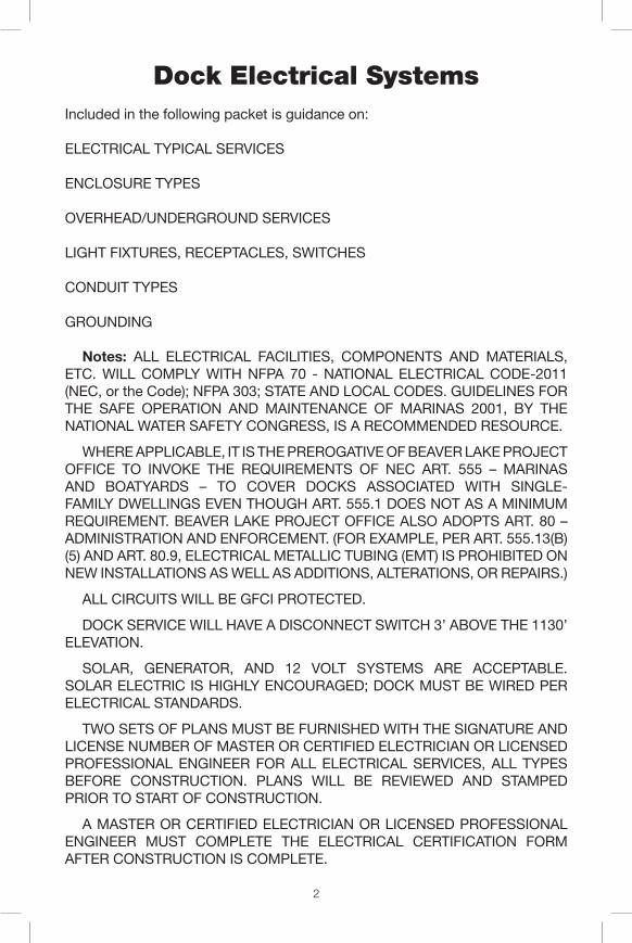
Typical Installations
New Service, Underground Power
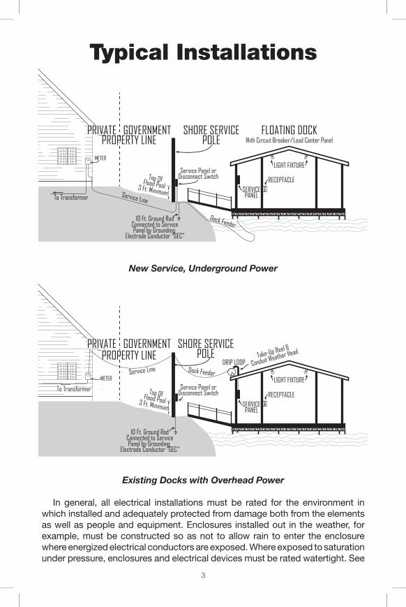
Existing Docks with Overhead Power
In general, all electrical installations must be rated for the environment in which installed and adequately protected from damage both from the elements as well as people and equipment. Enclosures installed out in the weather, for example, must be constructed so as not to allow rain to enter the enclosure where energized electrical conductors are exposed. Where exposed to saturation under pressure, enclosures and electrical devices must be rated watertight. See
METER
METER
SERVICEPANELTo Transformer
Service Panel orDisconnect Switch
LIGHT FIXTURE
RECEPTACLE
10 Ft. Ground RodConnected to ServicePanel by Grounding
Electrode Conductor “GEC”
3 Ft. MinimumService Line
FLOATING DOCKWith Circuit Breaker/Load Center Panel
SHORE SERVICEPOLE
SERVICEPANEL
Top OfFlood Pool
Service Panel orDisconnect Switch
LIGHT FIXTURE
Take-Up Reel &
Conduit Weather Head
DRIP LOOP
RECEPTACLE
TRANSFORMER POLE(Point of CommercialService and Meter)
DOCK SERVICEDISCONNECT SWITCH
(3 Ft. Above TopOf Flood Pool)
DOCK CIRCUITS:(Branch Circuits With Equipment
Grounding Conductor “EGC” To LightsAnd Weather Proof Receptacles/WP)
OVERHEAD/UNDERGROUND/UNDERWATERWITH EQUIPMENT GROUNDING CONDUCTOR “GEC”
10 Ft. Ground RodConnected to ServicePanel by Grounding
Electrode Conductor “GEC”
3 Ft. Minimum
Dock Feeder Service Line
SHORE SERVICEPOLE
ROUTES: OVERHEAD/UNDERGROUND
SERVICE LINE DOCK FEEDER
TYPICAL BOAT DOCK ENVIRONMENT
THE 10 AND 3 RULE
SERVICE POLE
PoleBurial
6 Ft. Minimum
Ground Rod
Panel Top at ≤ 6’6” Above Ground Level
Conduit Support Within 3’ Of Enclosure
Type “UF” (Underground Feeder) Direct Burial Cable
Bushing
Rigid Conduit (Schedule 40 or 80 PVC PLASTIC), “RMC” (Rigid Metal Conduit), or“IMC” (Intermdeiate Metal Conduit
Top OfFlood Pool
Top OfFlood Pool
Dock Feeder
PRIVATE GOVERNMENT PROPERTY LINE
PRIVATE GOVERNMENT PROPERTY LINE
PRIVATE GOVERNMENT PROPERTY LINE
PRIVATE GOVERNMENT PROPERTY LINE
To Transformer
SERVICEPANELTop OfPanel≤ 6’6”
LIGHTS ≥ 7’6”
Drip Loop
3 Ft. Minimum
Take-Up Reel &
Conduit Weather Head
Damp A
reaWet
Area
Wind and Rain
To 45° UnderCanopy
RECEPTACLE or SWITCH 36-48”
Wet Area-30”Deck Elevation-12”FLOTATION
Dock Feeder
Waves - Wet Area Waves - Wet Area
J-BOX OR PANEL
SUPPORTSUPPORT
SUPPORTSUPPORT
COUPLINGCOUPLING
3’ 10’10’
4’ 3’10’ 10’
10’
METER
METER
SERVICEPANELTo Transformer
Service Panel orDisconnect Switch
LIGHT FIXTURE
RECEPTACLE
10 Ft. Ground RodConnected to ServicePanel by Grounding
Electrode Conductor “GEC”
3 Ft. MinimumService Line
FLOATING DOCKWith Circuit Breaker/Load Center Panel
SHORE SERVICEPOLE
SERVICEPANEL
Top OfFlood Pool
Service Panel orDisconnect Switch
LIGHT FIXTURE
Take-Up Reel &
Conduit Weather Head
DRIP LOOP
RECEPTACLE
TRANSFORMER POLE(Point of CommercialService and Meter)
DOCK SERVICEDISCONNECT SWITCH
(3 Ft. Above TopOf Flood Pool)
DOCK CIRCUITS:(Branch Circuits With Equipment
Grounding Conductor “EGC” To LightsAnd Weather Proof Receptacles/WP)
OVERHEAD/UNDERGROUND/UNDERWATERWITH EQUIPMENT GROUNDING CONDUCTOR “GEC”
10 Ft. Ground RodConnected to ServicePanel by Grounding
Electrode Conductor “GEC”
3 Ft. Minimum
Dock Feeder Service Line
SHORE SERVICEPOLE
ROUTES: OVERHEAD/UNDERGROUND
SERVICE LINE DOCK FEEDER
TYPICAL BOAT DOCK ENVIRONMENT
THE 10 AND 3 RULE
SERVICE POLE
PoleBurial
6 Ft. Minimum
Ground Rod
Panel Top at ≤ 6’6” Above Ground Level
Conduit Support Within 3’ Of Enclosure
Type “UF” (Underground Feeder) Direct Burial Cable
Bushing
Rigid Conduit (Schedule 40 or 80 PVC PLASTIC), “RMC” (Rigid Metal Conduit), or“IMC” (Intermdeiate Metal Conduit
Top OfFlood Pool
Top OfFlood Pool
Dock Feeder
PRIVATE GOVERNMENT PROPERTY LINE
PRIVATE GOVERNMENT PROPERTY LINE
PRIVATE GOVERNMENT PROPERTY LINE
PRIVATE GOVERNMENT PROPERTY LINE
To Transformer
SERVICEPANELTop OfPanel≤ 6’6”
LIGHTS ≥ 7’6”
Drip Loop
3 Ft. Minimum
Take-Up Reel &
Conduit Weather Head
Damp A
reaWet
Area
Wind and Rain
To 45° UnderCanopy
RECEPTACLE or SWITCH 36-48”
Wet Area-30”Deck Elevation-12”FLOTATION
Dock Feeder
Waves - Wet Area Waves - Wet Area
J-BOX OR PANEL
SUPPORTSUPPORT
SUPPORTSUPPORT
COUPLINGCOUPLING
3’ 10’10’
4’ 3’10’ 10’
10’
4
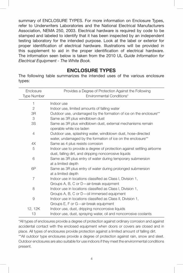
summary of ENCLOSURE TYPES. For more information on Enclosure Types, refer to Underwriters Laboratories and the National Electrical Manufacturers Association, NEMA 250, 2003. Electrical hardware is required by code to be stamped and labeled to identify that it has been inspected by an independent testing laboratory for the intended purpose. Look at the label or exterior for proper identification of electrical hardware. Illustrations will be provided in this supplement to aid in the proper identification of electrical hardware. The information seen below is taken from the 2010 UL Guide Information for Electrical Equipment - The White Book.
ENCLOSURE TYPES The following table summarizes the intended uses of the various enclosure types:
Enclosure Provides a Degree of Protection Against the Following Type Number Environmental Conditions*
1 Indoor use 2 Indoor use, limited amounts of falling water 3R Outdoor use, undamaged by the formation of ice on the enclosure** 3 Same as 3R plus windblown dust 3S Same as 3R plus windblown dust, external mechanisms remain operable while ice laden 4 Outdoor use, splashing water, windblown dust, hose-directed water, undamaged by the formation of ice on the enclosure** 4X Same as 4 plus resists corrosion 5 Indoor use to provide a degree of protection against settling airborne dust, falling dirt, and dripping noncorrosive liquids 6 Same as 3R plus entry of water during temporary submersion at a limited depth 6P Same as 3R plus entry of water during prolonged submersion at a limited depth 7 Indoor use in locations classified as Class I, Division 1, Groups A, B, C or D—air-break equipment 8 Indoor use in locations classified as Class I, Division 1, Groups A, B, C or D—oil immersed equipment 9 Indoor use in locations classified as Class II, Division 1, Groups E, F or G—air-break equipment 12, 12K Indoor use, dust, dripping noncorrosive liquids 13 Indoor use, dust, spraying water, oil and noncorrosive coolants
*All types of enclosures provide a degree of protection against ordinary corrosion and against accidental contact with the enclosed equipment when doors or covers are closed and in place. All types of enclosures provide protection against a limited amount of falling dirt.**All outdoor type enclosures provide a degree of protection against rain, snow and sleet. Outdoor enclosures are also suitable for use indoors if they meet the environmental conditions present.
5
The National Electrical Code, “NEC,” gives specific rules to be followed. However, good common sense in protecting personnel from electrical shock hazards as well as maintaining the insulation integrity of wiring and electrical devices is the major theme throughout this code. All live electrical components must be insulated and guarded by enclosures from contact by personnel. Anything which will damage or compromise the insulating or protective characteristics of wiring installations is most likely covered somewhere within the text of the Code. Holes which allow the entrance of bugs, water, dust, and the accumulation of excessive moisture are not allowed. Wiring should also be protected from sharp edges of conduits, enclosures, and structural features that can cut through either the outer cable jacket or the insulation of the conductors themselves. This would allow exposed metal objects, which personnel are likely to make contact with, to be energized, thereby creating a deadly shock hazard. Circuit breakers with proper grounding of the electrical system, as well as Ground Fault Circuit Interrupters, provide some degree of protection from shock hazards. Proper grounding of electrical installations is critical to the safety of personnel.
Starting from the incoming electrical service/meter pole, we will trace the electrical service out to the boat dock electrical devices/lights/receptacles, etc. Often the service/meter pole and dock shore service pole will be separate. We will cover the applicable rules and give examples and illustrations where necessary to clarify the NEC and SWLR 1130-2-48 dated 6 Jan 03. Direct references will be made to the NEC and the SWLR as needed. These should be referred to for more information when required. Refer to paragraph “1” pages G-5 through 9 of the SWLR.
Overhead services are not allowed on new applications per SWLR-2-48. Existing overhead service or feeder lines must comply with NEC Art. 555.13(B), 225.18, and 230.24, summarized as follows: (1) 10 ft – above grade, sidewalks, platform, or projection where accessible to
pedestrians only(2) 12 ft – over residential property and driveways, and those commercial areas
not subject to truck traffic(3) 15 ft – for those areas listed in the 12 ft classification where the voltage
exceeds 300V to ground(4) 18 ft – over areas subject to truck traffic, or other land traversed by vehicles,
such as cultivated, grazing, forest, and orchard(5) 52 ft – over navigable waterways where sailboats are commonly operated
(per ER 1110-2-4401)
Overhead services or feeders must be a minimum of 8 ft above the roof for an area extending 3 ft in all directions from the canopy, for roofs pitched less than 4 in. in 12 in. For roofs pitched 4 in. in 12 in. or steeper, this minimum clearance can be reduced to 3 ft above the roof, for an area extending 3 ft in all directions from the canopy. This requirement can be reduced to 18” if less than 6 ft of cable, or 4 ft over a roof on a 4 to 12 slope. (Refer to NEC Art. 555.13(B), 225.18, and 230.24 for the exact Code verbiage.)
6
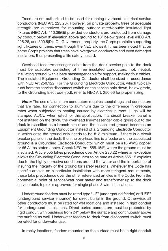
Trees are not authorized to be used for running overhead electrical service conductors (NEC Art. 225.26). However, on private property, trees of adequate strength are authorized for mounting outdoor rated/double insulated light fixtures (NEC Art. 410.36(G)) provided conductors are protected from damage by conduit below 8’ elevation above ground to 18” below grade level (NEC Art. 225.26, and 300.5(D)). On Government property, the Corps prohibits supporting light fixtures on trees, even though the NEC allows it. It has been noted that on some Corps projects that trees have overgrown conductors and even damaged insulators, thus presenting a life safety hazard.
Overhead feeder/messenger cable from the dock service pole to the dock must be quadplex consisting of three insulated conductors; hot, neutral, insulating ground, with a bare messenger cable for support, making four cables. The insulated Equipment Grounding Conductor shall be sized in accordance with NEC Art 250.122. For the Grounding Electrode Conductor, which typically runs from the service disconnect switch on the service pole down, below grade, to the Grounding Electrode (rod), refer to NEC Art. 250.66 for proper sizing.
Note: The use of aluminum conductors requires special lugs and connectors that are rated for connection to aluminum due to the difference in creepage rates when subjected to heating caused by electrical current. Lugs will be stamped AL/CU when rated for this application. If a circuit breaker panel is not installed on the dock, the overhead line/messenger cable going out to the dock is classified as a branch circuit and the associated ground becomes an Equipment Grounding Conductor instead of a Grounding Electrode Conductor in which case the ground only needs to be #12 minimum. If there is a circuit breaker panel on the dock, then the overhead line is a feeder and the associated ground is a Grounding Electrode Conductor which must be #18 AWG copper or #6 AL as stated above. Check NEC Art. 555.15(E) where the ground must be insulated. Article 555 takes precedence over Article 230.22 where an exception allows the Grounding Electrode Conductor to be bare as Article 555.15 explains due to the highly corrosive conditions around the water and the importance of insuring the integrity of the ground for safety reasons. Wherever the Code has specific articles on a particular installation with more stringent requirements, these take precedence over the other referenced articles in the Code. From the commercial point of service/watt hour meter and transformer up to the dock service pole, triplex is approved for single phase 3 wire installations.
Underground feeders must be rated type “UF” (underground feeder) or “USE” (underground service entrance) for direct burial in the ground. Otherwise, all other conductors must be rated for wet locations and installed in rigid conduit for underground installations. Direct buried conductors must be protected by rigid conduit with bushings from 24” below the surface and continuously above the surface as well. Underwater feeders to dock from disconnect switch must be rated for underwater use.
In rocky locations, feeders mounted on the surface must be in rigid conduit
7
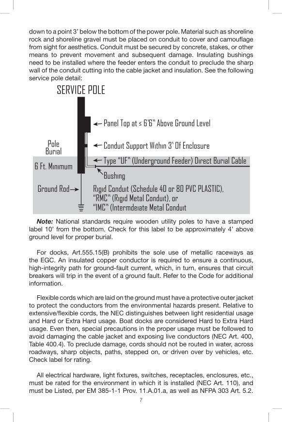
down to a point 3’ below the bottom of the power pole. Material such as shoreline rock and shoreline gravel must be placed on conduit to cover and camouflage from sight for aesthetics. Conduit must be secured by concrete, stakes, or other means to prevent movement and subsequent damage. Insulating bushings need to be installed where the feeder enters the conduit to preclude the sharp wall of the conduit cutting into the cable jacket and insulation. See the following service pole detail:
Note: National standards require wooden utility poles to have a stamped label 10’ from the bottom. Check for this label to be approximately 4’ above ground level for proper burial.
For docks, Art.555.15(B) prohibits the sole use of metallic raceways as the EGC. An insulated copper conductor is required to ensure a continuous, high-integrity path for ground-fault current, which, in turn, ensures that circuit breakers will trip in the event of a ground fault. Refer to the Code for additional information.
Flexible cords which are laid on the ground must have a protective outer jacket to protect the conductors from the environmental hazards present. Relative to extensive/flexible cords, the NEC distinguishes between light residential usage and Hard or Extra Hard usage. Boat docks are considered Hard to Extra Hard usage. Even then, special precautions in the proper usage must be followed to avoid damaging the cable jacket and exposing live conductors (NEC Art. 400, Table 400.4). To preclude damage, cords should not be routed in water, across roadways, sharp objects, paths, stepped on, or driven over by vehicles, etc. Check label for rating.
All electrical hardware, light fixtures, switches, receptacles, enclosures, etc., must be rated for the environment in which it is installed (NEC Art. 110), and must be Listed, per EM 385-1-1 Prov. 11.A.01.a, as well as NFPA 303 Art. 5.2.
METER
METER
SERVICEPANELTo Transformer
Service Panel orDisconnect Switch
LIGHT FIXTURE
RECEPTACLE
10 Ft. Ground RodConnected to ServicePanel by Grounding
Electrode Conductor “GEC”
3 Ft. MinimumService Line
FLOATING DOCKWith Circuit Breaker/Load Center Panel
SHORE SERVICEPOLE
SERVICEPANEL
Top OfFlood Pool
Service Panel orDisconnect Switch
LIGHT FIXTURE
Take-Up Reel &
Conduit Weather Head
DRIP LOOP
RECEPTACLE
TRANSFORMER POLE(Point of CommercialService and Meter)
DOCK SERVICEDISCONNECT SWITCH
(3 Ft. Above TopOf Flood Pool)
DOCK CIRCUITS:(Branch Circuits With Equipment
Grounding Conductor “EGC” To LightsAnd Weather Proof Receptacles/WP)
OVERHEAD/UNDERGROUND/UNDERWATERWITH EQUIPMENT GROUNDING CONDUCTOR “GEC”
10 Ft. Ground RodConnected to ServicePanel by Grounding
Electrode Conductor “GEC”
3 Ft. Minimum
Dock Feeder Service Line
SHORE SERVICEPOLE
ROUTES: OVERHEAD/UNDERGROUND
SERVICE LINE DOCK FEEDER
TYPICAL BOAT DOCK ENVIRONMENT
THE 10 AND 3 RULE
SERVICE POLE
PoleBurial
6 Ft. Minimum
Ground Rod
Panel Top at ≤ 6’6” Above Ground Level
Conduit Support Within 3’ Of Enclosure
Type “UF” (Underground Feeder) Direct Burial Cable
Bushing
Rigid Conduit (Schedule 40 or 80 PVC PLASTIC), “RMC” (Rigid Metal Conduit), or“IMC” (Intermdeiate Metal Conduit
Top OfFlood Pool
Top OfFlood Pool
Dock Feeder
PRIVATE GOVERNMENT PROPERTY LINE
PRIVATE GOVERNMENT PROPERTY LINE
PRIVATE GOVERNMENT PROPERTY LINE
PRIVATE GOVERNMENT PROPERTY LINE
To Transformer
SERVICEPANELTop OfPanel≤ 6’6”
LIGHTS ≥ 7’6”
Drip Loop
3 Ft. Minimum
Take-Up Reel &
Conduit Weather Head
Damp A
reaWet
Area
Wind and Rain
To 45° UnderCanopy
RECEPTACLE or SWITCH 36-48”
Wet Area-30”Deck Elevation-12”FLOTATION
Dock Feeder
Waves - Wet Area Waves - Wet Area
J-BOX OR PANEL
SUPPORTSUPPORT
SUPPORTSUPPORT
COUPLINGCOUPLING
3’ 10’10’
4’ 3’10’ 10’
10’
8
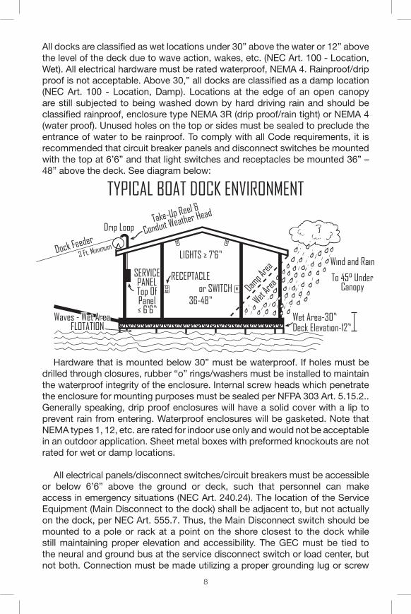
All docks are classified as wet locations under 30” above the water or 12” above the level of the deck due to wave action, wakes, etc. (NEC Art. 100 - Location, Wet). All electrical hardware must be rated waterproof, NEMA 4. Rainproof/drip proof is not acceptable. Above 30,” all docks are classified as a damp location (NEC Art. 100 - Location, Damp). Locations at the edge of an open canopy are still subjected to being washed down by hard driving rain and should be classified rainproof, enclosure type NEMA 3R (drip proof/rain tight) or NEMA 4 (water proof). Unused holes on the top or sides must be sealed to preclude the entrance of water to be rainproof. To comply with all Code requirements, it is recommended that circuit breaker panels and disconnect switches be mounted with the top at 6’6” and that light switches and receptacles be mounted 36” – 48” above the deck. See diagram below:
Hardware that is mounted below 30” must be waterproof. If holes must be drilled through closures, rubber “o” rings/washers must be installed to maintain the waterproof integrity of the enclosure. Internal screw heads which penetrate the enclosure for mounting purposes must be sealed per NFPA 303 Art. 5.15.2.. Generally speaking, drip proof enclosures will have a solid cover with a lip to prevent rain from entering. Waterproof enclosures will be gasketed. Note that NEMA types 1, 12, etc. are rated for indoor use only and would not be acceptable in an outdoor application. Sheet metal boxes with preformed knockouts are not rated for wet or damp locations.
All electrical panels/disconnect switches/circuit breakers must be accessible or below 6’6” above the ground or deck, such that personnel can make access in emergency situations (NEC Art. 240.24). The location of the Service Equipment (Main Disconnect to the dock) shall be adjacent to, but not actually on the dock, per NEC Art. 555.7. Thus, the Main Disconnect switch should be mounted to a pole or rack at a point on the shore closest to the dock while still maintaining proper elevation and accessibility. The GEC must be tied to the neural and ground bus at the service disconnect switch or load center, but not both. Connection must be made utilizing a proper grounding lug or screw
METER
METER
SERVICEPANELTo Transformer
Service Panel orDisconnect Switch
LIGHT FIXTURE
RECEPTACLE
10 Ft. Ground RodConnected to ServicePanel by Grounding
Electrode Conductor “GEC”
3 Ft. MinimumService Line
FLOATING DOCKWith Circuit Breaker/Load Center Panel
SHORE SERVICEPOLE
SERVICEPANEL
Top OfFlood Pool
Service Panel orDisconnect Switch
LIGHT FIXTURE
Take-Up Reel &
Conduit Weather Head
DRIP LOOP
RECEPTACLE
TRANSFORMER POLE(Point of CommercialService and Meter)
DOCK SERVICEDISCONNECT SWITCH
(3 Ft. Above TopOf Flood Pool)
DOCK CIRCUITS:(Branch Circuits With Equipment
Grounding Conductor “EGC” To LightsAnd Weather Proof Receptacles/WP)
OVERHEAD/UNDERGROUND/UNDERWATERWITH EQUIPMENT GROUNDING CONDUCTOR “GEC”
10 Ft. Ground RodConnected to ServicePanel by Grounding
Electrode Conductor “GEC”
3 Ft. Minimum
Dock Feeder Service Line
SHORE SERVICEPOLE
ROUTES: OVERHEAD/UNDERGROUND
SERVICE LINE DOCK FEEDER
TYPICAL BOAT DOCK ENVIRONMENT
THE 10 AND 3 RULE
SERVICE POLE
PoleBurial
6 Ft. Minimum
Ground Rod
Panel Top at ≤ 6’6” Above Ground Level
Conduit Support Within 3’ Of Enclosure
Type “UF” (Underground Feeder) Direct Burial Cable
Bushing
Rigid Conduit (Schedule 40 or 80 PVC PLASTIC), “RMC” (Rigid Metal Conduit), or“IMC” (Intermdeiate Metal Conduit
Top OfFlood Pool
Top OfFlood Pool
Dock Feeder
PRIVATE GOVERNMENT PROPERTY LINE
PRIVATE GOVERNMENT PROPERTY LINE
PRIVATE GOVERNMENT PROPERTY LINE
PRIVATE GOVERNMENT PROPERTY LINE
To Transformer
SERVICEPANELTop OfPanel≤ 6’6”
LIGHTS ≥ 7’6”
Drip Loop
3 Ft. Minimum
Take-Up Reel &
Conduit Weather Head
Damp A
reaWet
AreaWind and Rain
To 45° UnderCanopy
RECEPTACLE or SWITCH 36-48”
Wet Area-30”Deck Elevation-12”FLOTATION
Dock Feeder
Waves - Wet Area Waves - Wet Area
J-BOX OR PANEL
SUPPORTSUPPORT
SUPPORTSUPPORT
COUPLINGCOUPLING
3’ 10’10’
4’ 3’10’ 10’
10’
9
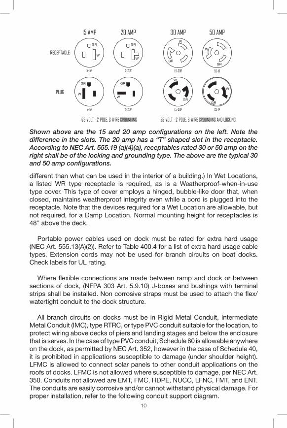
attached to the solid metal of the box, not to the mounting screws. Various manufacturers will color this screw green for identification. The NEC has found that mounting screws do not provide adequate surface contact area for proper ground connection. This ground connection is critical such that circuit breakers will trip in the event of a ground fault to preclude electrocution or fire hazards. Circuit breakers also monitor the current flowing through conductors between the hot and neutral and will trip at the predetermined setting (20 amps, etc.) to prevent a fire due to overheating which will melt the insulation. Either 20 amp or 15 amp receptacles are authorized for convenience outlets on private docks, but not for shore power where 20 amp is the minimum. Shore power outlets must also be twist lock and 30 amp for boats longer than 20 feet. Refer to NEC Art. 555.19 for more information about receptacles.
According to SWLR 1130-2-48 Regulatory, all houseboats with sanitation devices must be moored in commercial marinas. Houseboats with MSDs are not allowed in private boat dock facilities.
Light fixtures (Luminaires) must be rated and installed per NEC Art. 410.10 (A), thus fixtures subject to direct rain shall be marked “Suitable for Wet Locations,” and all other fixtures shall be marked “Suitable for Wet Locations” or “Suitable for Damp Locations” .To make this determination, as a rule of thumb, any fixture or device above/inside an imaginary plane extending 45 degrees from the eve of the roof to the interior of the dock shall be suitable for Damp Locations, as a minimum; any fixture of device below/outside this imaginary plane shall be considered subject to direct rain, and therefore shall be suitable for Wet Locations. Spot lights that are gasketed and rated weatherproof are authorized. Otherwise, all Wet-rated fixtures should be guarded and gasketed. Fixtures must be located where not subject to damage from contact with stored or moving materials (NFPA 303 Art. 5.14.2). Due to the high operating temperature of light bulbs, fixtures must be located such that unshielded bulbs are kept a safe distance away from flammable materials such as wooded members/trusses (NEC Art. 410.11 & 12).
Receptacle and switch boxes must be grounded per NEC Art. 250. An
equipment grounding conductor sized per NEC Art. 250.122, but not smaller than #12 AWG, must be run to all branch circuits. Per NEC Art. 555.19(B)(1), 15- and 20-amp receptacles must have GFCI protection, either through utilization of GFCI receptacles or a GFCI circuit breaker. Per the definitions for Damp Locations and Wet Locations, as defined by the Code, as well as mentioned above (recall discussion of the imaginary plane for rainfall), regarding luminaires, the same rules apply for dock receptacles. In Damp Locations, a listed Weather-Resistant type (WR) receptacle is required, as is a Weatherproof-with-no-plug-inserted type cover. This type of cover employs a spring-loaded flap (or a screw-on cap for a single-outlet type) that is only weatherproof when the outlet is not being used, hence Weatherproof with no plug inserted. This type of cover is, therefore, no longer weatherproof when a cord is plugged into the receptacle, because the cover is in the open position. (Note that a WR receptacle rating is
10
different than what can be used in the interior of a building.) In Wet Locations, a listed WR type receptacle is required, as is a Weatherproof-when-in-use type cover. This type of cover employs a hinged, bubble-like door that, when closed, maintains weatherproof integrity even while a cord is plugged into the receptacle. Note that the devices required for a Wet Location are allowable, but not required, for a Damp Location. Normal mounting height for receptacles is 48” above the deck.
Portable power cables used on dock must be rated for extra hard usage (NEC Art. 555.13(A)(2)). Refer to Table 400.4 for a list of extra hard usage cable types. Extension cords may not be used for branch circuits on boat docks. Check labels for UL rating.
Where flexible connections are made between ramp and dock or between sections of dock, (NFPA 303 Art. 5.9.10) J-boxes and bushings with terminal strips shall be installed. Non corrosive straps must be used to attach the flex/watertight conduit to the dock structure.
All branch circuits on docks must be in Rigid Metal Conduit, Intermediate Metal Conduit (IMC), type RTRC, or type PVC conduit suitable for the location, to protect wiring above decks of piers and landing stages and below the enclosure that is serves. In the case of type PVC conduit, Schedule 80 is allowable anywhere on the dock, as permitted by NEC Art. 352, however in the case of Schedule 40, it is prohibited in applications susceptible to damage (under shoulder height). LFMC is allowed to connect solar panels to other conduit applications on the roofs of docks. LFMC is not allowed where susceptible to damage, per NEC Art. 350. Conduits not allowed are EMT, FMC, HDPE, NUCC, LFNC, FMT, and ENT. The conduits are easily corrosive and/or cannot withstand physical damage. For proper installation, refer to the following conduit support diagram.
Shown above are the 15 and 20 amp configurations on the left. Note the difference in the slots. The 20 amp has a “T” shaped slot in the receptacle. According to NEC Art. 555.19 (a)(4)(a), receptables rated 30 or 50 amp on the right shall be of the locking and grounding type. The above are the typical 30 and 50 amp configurations.
125-VOLT - 2-POLE, 3-WIRE GROUNDING AND LOCKING
RECEPTACLE
125-VOLT - 2-POLE, 3-WIRE GROUNDING
PLUG
50 AMP30 AMP
L5-30R
W
GR
L5-30P
W
GR
SS-1R
W
GR
SS-1P
W
GR
20 AMP15 AMP
5-15R
W
GR
5-20R
W
GR
5-20P
W
GR
5-15P
W
GR
11
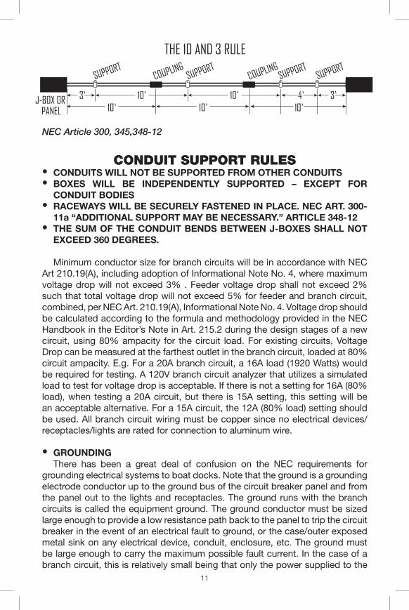
CONDUIT SUPPORT RULES● CONDUITS WILL NOT BE SUPPORTED FROM OTHER CONDUITS● BOXES WILL BE INDEPENDENTLY SUPPORTED – EXCEPT FOR
CONDUIT BODIES● RACEWAYS WILL BE SECURELY FASTENED IN PLACE. NEC ART. 300-
11a “ADDITIONAL SUPPORT MAY BE NECESSARY.” ARTICLE 348-12● THE SUM OF THE CONDUIT BENDS BETWEEN J-BOXES SHALL NOT
EXCEED 360 DEGREES.
Minimum conductor size for branch circuits will be in accordance with NEC Art 210.19(A), including adoption of Informational Note No. 4, where maximum voltage drop will not exceed 3% . Feeder voltage drop shall not exceed 2% such that total voltage drop will not exceed 5% for feeder and branch circuit, combined, per NEC Art. 210.19(A), Informational Note No. 4. Voltage drop should be calculated according to the formula and methodology provided in the NEC Handbook in the Editor’s Note in Art. 215.2 during the design stages of a new circuit, using 80% ampacity for the circuit load. For existing circuits, Voltage Drop can be measured at the farthest outlet in the branch circuit, loaded at 80% circuit ampacity. E.g. For a 20A branch circuit, a 16A load (1920 Watts) would be required for testing. A 120V branch circuit analyzer that utilizes a simulated load to test for voltage drop is acceptable. If there is not a setting for 16A (80% load), when testing a 20A circuit, but there is 15A setting, this setting will be an acceptable alternative. For a 15A circuit, the 12A (80% load) setting should be used. All branch circuit wiring must be copper since no electrical devices/receptacles/lights are rated for connection to aluminum wire.
● GROUNDINGThere has been a great deal of confusion on the NEC requirements for
grounding electrical systems to boat docks. Note that the ground is a grounding electrode conductor up to the ground bus of the circuit breaker panel and from the panel out to the lights and receptacles. The ground runs with the branch circuits is called the equipment ground. The ground conductor must be sized large enough to provide a low resistance path back to the panel to trip the circuit breaker in the event of an electrical fault to ground, or the case/outer exposed metal sink on any electrical device, conduit, enclosure, etc. The ground must be large enough to carry the maximum possible fault current. In the case of a branch circuit, this is relatively small being that only the power supplied to the
METER
METER
SERVICEPANELTo Transformer
Service Panel orDisconnect Switch
LIGHT FIXTURE
RECEPTACLE
10 Ft. Ground RodConnected to ServicePanel by Grounding
Electrode Conductor “GEC”
3 Ft. MinimumService Line
FLOATING DOCKWith Circuit Breaker/Load Center Panel
SHORE SERVICEPOLE
SERVICEPANEL
Top OfFlood Pool
Service Panel orDisconnect Switch
LIGHT FIXTURE
Take-Up Reel &
Conduit Weather Head
DRIP LOOP
RECEPTACLE
TRANSFORMER POLE(Point of CommercialService and Meter)
DOCK SERVICEDISCONNECT SWITCH
(3 Ft. Above TopOf Flood Pool)
DOCK CIRCUITS:(Branch Circuits With Equipment
Grounding Conductor “EGC” To LightsAnd Weather Proof Receptacles/WP)
OVERHEAD/UNDERGROUND/UNDERWATERWITH EQUIPMENT GROUNDING CONDUCTOR “GEC”
10 Ft. Ground RodConnected to ServicePanel by Grounding
Electrode Conductor “GEC”
3 Ft. Minimum
Dock Feeder Service Line
SHORE SERVICEPOLE
ROUTES: OVERHEAD/UNDERGROUND
SERVICE LINE DOCK FEEDER
TYPICAL BOAT DOCK ENVIRONMENT
THE 10 AND 3 RULE
SERVICE POLE
PoleBurial
6 Ft. Minimum
Ground Rod
Panel Top at ≤ 6’6” Above Ground Level
Conduit Support Within 3’ Of Enclosure
Type “UF” (Underground Feeder) Direct Burial Cable
Bushing
Rigid Conduit (Schedule 40 or 80 PVC PLASTIC), “RMC” (Rigid Metal Conduit), or“IMC” (Intermdeiate Metal Conduit
Top OfFlood Pool
Top OfFlood Pool
Dock Feeder
PRIVATE GOVERNMENT PROPERTY LINE
PRIVATE GOVERNMENT PROPERTY LINE
PRIVATE GOVERNMENT PROPERTY LINE
PRIVATE GOVERNMENT PROPERTY LINE
To Transformer
SERVICEPANELTop OfPanel≤ 6’6”
LIGHTS ≥ 7’6”
Drip Loop
3 Ft. Minimum
Take-Up Reel &
Conduit Weather Head
Damp A
reaWet
Area
Wind and Rain
To 45° UnderCanopy
RECEPTACLE or SWITCH 36-48”
Wet Area-30”Deck Elevation-12”FLOTATION
Dock Feeder
Waves - Wet Area Waves - Wet Area
J-BOX OR PANEL
SUPPORTSUPPORT
SUPPORTSUPPORT
COUPLINGCOUPLING
3’ 10’10’
4’ 3’10’ 10’
10’
NEC Article 300, 345,348-12
12
one branch circuit comes into play. In the case of the entire circuit breaker panel where the grounding electrode conductor provides protection, the fault current can be much larger. Therefore, the grounding electrode conductor is required by code to be much larger to protect the numerous branch circuits originating in the circuit breaker panel or in the electrical service. Electrical faults can occur between conductors a hot and a neutral, or hot and ground. Ground consisting of the grounding conductor system, the exposed metal in the case/enclosures of electrical equipment, and metal conduit/raceway systems. This protects personnel from being electrocuted once the insulation on an electrical conductor is compromised by breaking the source of power to the affected circuit where the fault occurred. A typical electrical service will consist of a single device which provides a means of disconnecting power to the service. It will also include a panel or means of dividing up or distributing the electrical power to individual electrical devices with protection sized closely to the maximum capacity for each branch circuit and major feeder. This way the protective devices consisting of fuses or circuit breakers will interrupt the source of power to prevent major damage from occurring once a weak spot in the insulation is detected and too much current flows through the circuit or device that it was designed to carry.
The grounding electrode conductor, “GEC,” will run from the ground rod to the disconnect switch and then extend to the ground bus of the circuit breaker panel as a part of the feeder. Branch circuits include an equipment ground conductor from the ground bus out to the individual electrical devices such as the lights and receptacles. This can be the same size as the branch circuit conductors or #12 AWG in most cases. Depending on which portion, “GEC” or “EGC,” of the service is run over the water, the feeder or the branch circuit will determine what size the ground can be and whether or not it must be insulated.