
Bay Bridge Panel Report - DRAFT 7-6...
33
Technical Review of Design and Construction of New East Span of San Francisco-Oakland Bay Bridge Friday, March 4, 2022 Panelists: Jack Baker, Ph.D. (Chair) Reginald DesRoches, Ph.D. Robert Gilbert, Ph.D., P.E. Youssef Hashash, Ph.D., P.E. Roberto T. Leon, Ph.D., P.E. Sena Kumarasena, Ph.D., P.E. Submitted to: The California Senate Transportation and Housing Committee Draft: Friday, March 4, 2022 Page 1 of 33 SRC Technical Review
Transcript of Bay Bridge Panel Report - DRAFT 7-6...
Technical Review of Design and Construction of New East Span of San Francisco-Oakland Bay Bridge
Saturday, May 6, 2023
Panelists:
Jack Baker, Ph.D.
(Chair) Reginald DesRoches, Ph.D.
Robert Gilbert, Ph.D., P.E.
Youssef Hashash, Ph.D., P.E.
Roberto T. Leon, Ph.D., P.E.
Sena Kumarasena, Ph.D., P.E.
Submitted to:The California Senate Transportation and Housing Committee
Draft: Saturday, May 6, 2023 Page 1 of 22 SRC Technical Review
Table of Contents 1 Introduction..............................................................................................................................32 Task 1: Review the seismic design criteria for the bridge.......................................................4
2.1 Background and Overview................................................................................................42.2 Findings.............................................................................................................................4
2.2.1 Earthquake hazard and ground shaking.....................................................................42.2.2 Design criteria............................................................................................................52.2.3 Modeling assumptions...............................................................................................52.2.4 Risk analysis..............................................................................................................6
2.3 Recommendations.............................................................................................................63 Task 2: Quality of foundations in the main span (Part I).......................................................7
3.1 Background and Overview................................................................................................73.2 Findings.............................................................................................................................93.3 Recommendations.............................................................................................................9
4 Task 3: Quality of foundations in the main span (Part II)....................................................114.1 Background and Overview..............................................................................................114.2 Findings:..........................................................................................................................114.3 Recommendations...........................................................................................................12
5 Task 4: Review of Broken Bolts on Shear Keys S1& S2 and the Repair Implemented.......135.1 Background and Overview..............................................................................................13
5.1.1 Use of High Strength Steels in Anchor Bolts..........................................................135.1.2 Hydrogen Embrittlement.........................................................................................145.1.3 The Original Seismic Restraint System Design at Pier E2......................................145.1.4 Design Approach.....................................................................................................155.1.5 Shear-Key (S1 and S2) Anchor Bolt Failures..........................................................155.1.6 Remedial Action and Repair Following Discovery.................................................16
5.2 Findings...........................................................................................................................165.3 Recommendations...........................................................................................................175.4 Referenced Documents:..................................................................................................18
6 Summary, Conclusions, and Recommendations...................................................................20
Draft: Saturday, May 6, 2023 Page 2 of 22 SRC Technical Review

1 Introduction
The California Senate Transportation and Housing Committee assembled this panel of engineers to provide a high-level, independent review of the design and construction of the new East Span of the San Francisco-Oakland Bay Bridge. The review focuses primarily on the processes and procedures taken by the designers to provide for a bridge that can perform as a lifeline structure in the event of a large earthquake. The conclusions and recommendations of the panel are intended to be advisory in nature and could be factored in to the future operation and maintenance of this bridge as deemed fit.
The conclusions and recommendations of the panel are based on a high level review of documents provided by Caltrans and/or their subcontractors. In preparing the report, the committee had several meetings and phone calls with Caltrans and the design and construction team, several site visits to the bridge (prior to and following the bridge opening), and numerous conference calls among the committee. The work in this contract is limited to a high level review of existing documents and does not contemplate either the generation of new data or the checking of calculations provided in the extant reports.
Draft: Saturday, May 6, 2023 Page 3 of 22 SRC Technical Review
2 Task 1: Review the seismic design criteria for the bridge.
The panel shall report on the appropriateness of Caltrans’ approach, methodologies, and modeling assumptions as they pertain to the ability of the structure as designed to withstand the assumed design earthquakes and perform as a lifeline structure in the event of an earthquake that could come from the Hayward, San Andreas, or other faults in the Bay Area. This task shall be a very high-level assessment of the risk analysis performed by Caltrans.
2.1 Background and Overview
Questions have been raised as to the potential performance of the bridge in a future earthquake. Caltrans has stated that the bridge is designed to experience only minor damage and be operational shortly after a Safety Evaluation Earthquake (defined by a ground motion intensity exceeded on average once every 1500 years). Several well-publicized problems that occurred during construction of the bridge have raised questions as to whether the bridge is likely to provide this level of performance. This Task provides an overview of the general approach to designing the structure to achieve its stated performance goal. While prediction of performance in future earthquakes can never be made with certainty, it is possible to evaluate whether appropriate standards of care were followed in the design and analysis.
2.2 Findings
2.2.1 Earthquake hazard and ground shaking
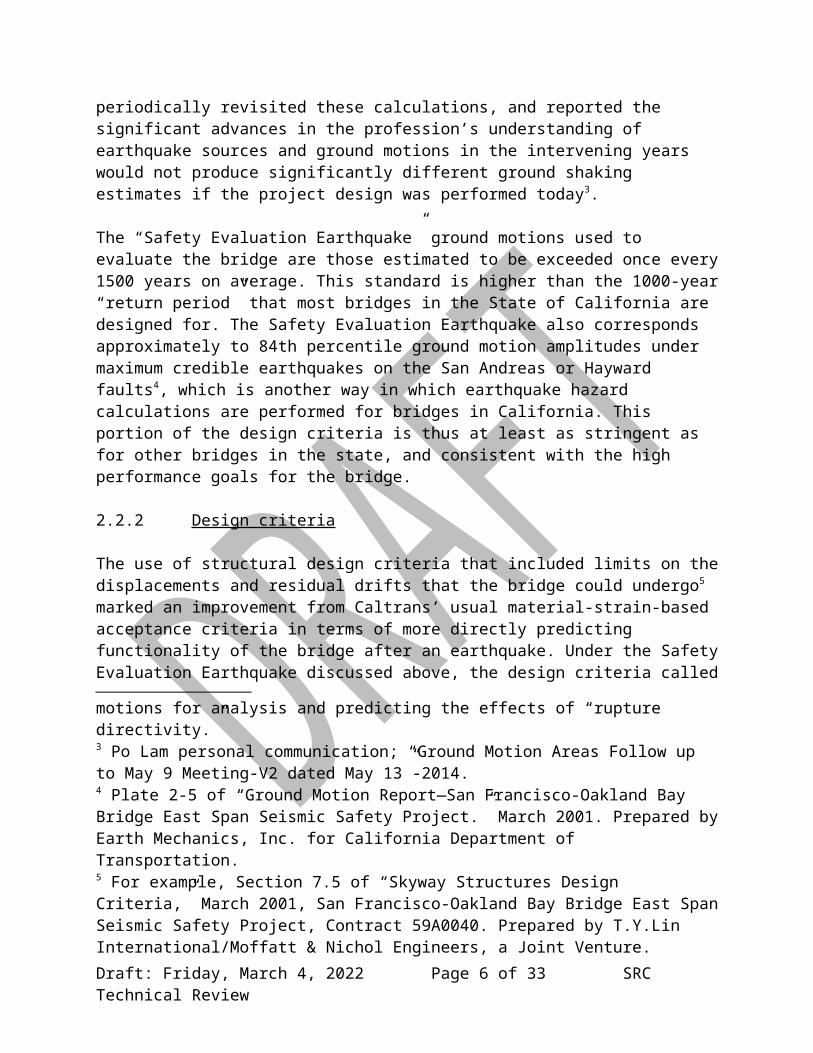
The calculations of the level of ground shaking that the bridge might experience1 were state-of –the-art at the time they were performed more than a decade ago2. The design team has periodically revisited these calculations, and reported the significant advances in the profession’s understanding of earthquake sources and ground motions in the intervening years would not produce significantly different ground shaking estimates if the project design was performed today3.
The “Safety Evaluation Earthquake” ground motions used to evaluate the bridge are those estimated to be exceeded once every 1500 years on average. This standard is higher than the 1000-year “return period” that most bridges in the State of California are designed for. The Safety Evaluation Earthquake also corresponds approximately to 84th percentile ground motion amplitudes under maximum credible earthquakes on the San Andreas or Hayward faults4, which is another way in which earthquake hazard calculations are performed for bridges in California.
1 “Ground Motion Report—San Francisco-Oakland Bay Bridge East Span Seismic Safety Project.” March 2001. Prepared by Earth Mechanics, Inc. for California Department of Transportation. 2 This project even significantly advanced the state of the art for earthquake hazard analysis in terms of developing ground motions for analysis and predicting the effects of “rupture directivity.”3 Po Lam personal communication; “Ground Motion Areas Follow up to May 9 Meeting-V2 dated May 13”-2014.
Draft: Saturday, May 6, 2023 Page 4 of 22 SRC Technical Review

This portion of the design criteria is thus at least as stringent as for other bridges in the state, and consistent with the high performance goals for the bridge.
2.2.2 Design criteria
The use of structural design criteria that included limits on the displacements and residual drifts that the bridge could undergo5 marked an improvement from Caltrans’ usual material-strain-based acceptance criteria in terms of more directly predicting functionality of the bridge after an earthquake. Under the Safety Evaluation Earthquake discussed above, the design criteria called for the structure to have “minor-to-moderate damage with some loss of operation”6, which is a much higher performance standard than for most bridges in the state. This higher standard is appropriate given the bridge’s designation as a lifeline structure.
The bridge was designed with additional conservatism in a number of areas (e.g., the T1 foundation, as discussed in Task 3) to account for uncertainty in ground motions, ground conditions and imposed loads. However, there was no apparent systematic look at the system-level performance of the overall Bay Bridge, which may have indicated inconsistent benefits from conservative decisions at the component level. Moreover, the lack of a system-level evaluation can lead to unintended consequences in terms of bridge performance. The panel recommends that such a system-level risk assessment for the entire bridge be made to support monitoring, maintenance and operation decisions going forward.
2.2.3 Modeling assumptions
The bridge is a complex system, consisting of four independent bridge structures, associated foundation systems, and underlying foundation conditions that vary significantly in their characteristics along the bridge’s length. Given these complexities, a number of modeling assumptions must be made in order to evaluate the bridge’s performance, and uncertainties are inherent to such an evaluation. The general approach to model earthquake loading was rational: ground motions were generated at a reference rock level underneath the bridge, the motions were propagated through computer models of soil columns, and the motions were then propagated into the bridge models while considering differential motions at each pier. Structural analysis of the Self-Anchored Suspension Span and other bridge structures were performed using the latest tools and methodologies available at the time.
2.2.4 Risk analysis
4 Plate 2-5 of “Ground Motion Report—San Francisco-Oakland Bay Bridge East Span Seismic Safety Project.” March 2001. Prepared by Earth Mechanics, Inc. for California Department of Transportation.5 For example, Section 7.5 of “Skyway Structures Design Criteria,” March 2001, San Francisco-Oakland Bay Bridge East Span Seismic Safety Project, Contract 59A0040. Prepared by T.Y.Lin International/Moffatt & Nichol Engineers, a Joint Venture.6 For example, Section 7.2.2 of “Skyway Structures Design Criteria,” March 2001, San Francisco-Oakland Bay Bridge East Span Seismic Safety Project, Contract 59A0040. Prepared by T.Y.Lin International/Moffatt & Nichol Engineers, a Joint Venture.
Draft: Saturday, May 6, 2023 Page 5 of 22 SRC Technical Review
No formal Probabilistic Risk Assessment (PRA) was performed to understand the probability of a bridge failure and the most likely mechanisms of a failure. This approach was consistent with Caltrans’ practice for all bridges in the state, though Probabilistic Risk Assessments are commonly performed for other critical structures such as nuclear power plants and large offshore oil and gas facilities. The lack of a PRA limits stakeholders’ ability to evaluate the impact of design decisions in terms of the overall bridge’s reliability.
2.3 Recommendations
1. Caltrans should consider conducting a life-cycle cost assessment analysis, which would include an assessment of the durability and cost associated with maintaining the bridge.
2. Caltrans should perform a comprehensive, system-level failure mode analysis to better understand the potential modes of failure, expected sequence of potential failure, and the expected performance of the system, including uncertainties associated with the demands and capacities in the bridge.
Draft: Saturday, May 6, 2023 Page 6 of 22 SRC Technical Review

3 Task 2: Quality of foundations in the main span (Part I).
The panel shall address the questions that have been raised regarding the construction quality of deep foundation elements of the main tower of the Self-Anchored Suspension (SAS) span of the bridge and its associated 13 foundation piles due to possible problems with the oversight of the construction contractor and subcontractors by Caltrans. A number of external reports and studies have been developed by others to address this issue. The panel shall review these reports and studies and opine on the appropriateness of the methodologies used.
3.1 Background and Overview
The foundation for the main tower (Pier T-1) of the Self-Anchored Suspension bridge consists of 13 reinforced-concrete piles (or drilled shafts) installed 30 m into fresh sandstone7 bedrock. The foundation was designed such that the capacity of the system is governed by the axial capacity of the individual piles. The axial capacity of individual piles was designed using an appropriate value for the bond strength (maximum side shear capacity) between the concrete pile and the surrounding bedrock, assuming no contribution from side shear in the weathered bedrock and sediments overlying the fresh bedrock, and assuming no contribution from end bearing at the tip of the pile8. In addition, the piles were designed so that there is minimal deformation and the reinforced concrete shafts respond elastically in the most extreme loading condition considered, the earthquake loading with a return period of 1,500 years. Finally, sensitivity analyses were conducted to check that the bridge structure would satisfy design criteria if the piles were stiffer than assumed. The use of a conservative approach in design was warranted given uncertainty in dealing with a natural material (bedrock), given the challenges of constructing these piles offshore and given the importance of this foundation.
Each pile was constructed by drilling a 2.2-m diameter hole down 63 m below the base of the tower, approximately 40 m below the sea floor and 30 m into fresh bedrock. The top 33 m of the pile was encased in a 2.5-m diameter steel pipe. When the hole was open it contained sea water at the same elevation as the surrounding sea level. The final step of construction was to fill the hole with reinforced concrete. A steel cage of reinforcing bars was inserted into the hole. Concrete was then poured down a tremie pipe to the bottom of the hole, displacing the sea water. The tip of the tremie pipe was gradually lifted as the concrete filled the hole.Of the three elements that make up a pile - the upper steel casing, the steel reinforcing bars, and the concrete – the one that could not easily be inspected is the concrete because it was placed deep underground and through water. The design specifications for the concrete and the spacing of the reinforcing bars were therefore intended to facilitate the wet concrete completely filling the hole when it was placed as well as to provide for the required structural capacity of the pile once the concrete cured. In addition, the construction quality assurance program focused on
7 The Franciscan Formation bedrock is described as sandstone with thin interbeds of siltstone and claystone.8 Geotechnical Foundation Report for Yerba Buena Island Approach and Self-Anchored Suspension Bridge, San Francisco-Oakland Bay Bridge East Span Seismic Safety Project, Fugro-Earth Mechanics, June 30, 2002.
Draft: Saturday, May 6, 2023 Page 7 of 22 SRC Technical Review
making sure the concrete completely filled the hole during placement and that it had adequate strength after curing.
The following steps were taken during construction to assess the quality of the concrete:1. Measurements of the ability of the concrete to flow before it cured (a slump test is an
example of this type of testing – the larger the slump of the concrete the more readily it will flow);
2. Measurements of the strength of the concrete after it cured;3. Measurements of the volume of concrete placed versus the volume of the hole filled;4. Measurements of the density of the concrete in an approximate 75-mm wide zone around
the perimeter of the pile along its length (these measurements were made using a nuclear density device called a gamma-gamma logger that is lowered into small diameter plastic tubes attached to the reinforcing bars and are not filled with concrete);
5. Measurements of the stiffness (and indirectly the strength) of the concrete across the cross-section of the pile along its length (these measurements were made using acoustical waves that are directed across the pile between small diameter steel tubes attached to the reinforcing bars and are not filled with concrete); and
6. Observation and documentation of construction materials and methods.
The construction quality assurance program included provisions to mitigate potential problems that were identified based on measurements or observations.
The information and data collected from the construction quality assurance program indicate that the piles were constructed in accordance with the design specifications9. Problems were encountered with the ability of the concrete to flow during construction of the first pile (Pile Number 2). While the slump measurements for this concrete, about 175 mm, met design specifications10,11 and were within the range of industry guidelines at the time the foundation was designed12, they are a bit low relative to guidelines today for placing concrete in large-diameter shafts with similar spacing of reinforcing bars13. Before continuing with construction, the concrete mix design for the piles was revised to provide for better flow; slump measurements with the revised mix design were greater than 225 mm. No additional problems occurred during the remainder of the concrete placement for Pile Number 2 and the other 12 piles. The discontinuity between the original concrete and the new concrete in Pile Number 2, which was located approximately 5 m above the bottom of the pile, could not be made as strong due to the interruption in concrete placement. This discontinuity was detected as a zone of less dense and weaker material in both the gamma-gamma logger measurements and the acoustical wave
9 Foundation Construction Records, Cast-In-Drill-Hole Pile information, Volumes 1 through 710 Standard Specifications, State of California, Business, Transportation and Housing Agency, Department of Transportation, July 199911 Notice to Contractors and Special Provisions for Construction on State Highway in the city and County of San Francisco at Yerba Buena Island, District 04, Route 80, State of California Department of Transportation, October 17, 200312 Drilled Shafts: Construction Procedures and Design Methods, Federal Highway Administration, Publication No. FHWA-IF-99-025, August 199913 Drilled Shafts: Construction Procedures and LRFD Design Methods, Federal Highway Administration, Publication No. FHWA-NHI-10-016, 32014, May 2010
Draft: Saturday, May 6, 2023 Page 8 of 22 SRC Technical Review

measurements. It was mitigated by drilling a 0.36-m diameter hole down through the new concrete and into the old concrete and then grouting a 0.22-m diameter steel pipe across the discontinuity to make the discontinuity as strong as the pile above and below it.
The questions about the construction quality of the piles were raised because of the concerns with one of the Caltrans employees who performed the gamma-gamma testing. About one year after the piles for the main tower were constructed, this particular employee was found to have falsified gamma-gamma testing logs on other construction projects. Both Caltrans and the U.S. Department of Transportation conducted investigations into this employee to identify where records were falsified and whether there was a concern with the quality of the piles on any of those projects. Both investigations concluded that the gamma-gamma testing logs for the piles supporting the main tower were not falsified14,15. In addition, sensitivity analyses were conducted by the designers to study the potential effect of damaged piles on the pushover capacity of the tower foundation; the foundation satisfies ultimate capacity design checks even when assuming one pile is missing16.
3.2 Findings
The panel concludes that appropriate and generally accepted procedures were followed in the design and construction of the Tower Foundation (T1). We base this conclusion on the following information:
1. All available evidence indicates that the construction quality assurance program for the concrete tower foundation piles was implemented properly.
2. Separate investigations by Caltrans and the U.S. Department of Transportation into the possibility that a Caltrans employee falsified some quality assurance test records, which provided the basis for questions regarding the quality of the piles, both concluded that these tests were conducted properly on this project and that there are no indications of falsified records.
3. The actual capacity of the pile foundation is likely greater than what was assumed in design and the foundation will likely not be the weakest link in the bridge when subjected to an extreme earthquake load.
4. The analysis conducted indicates that the piles within the foundation system have some redundancy whereby even with a hypothetical significant loss of capacity in an individual pile the overall capacity of the tower foundation is sufficient to meet seismic demands.
3.3 Recommendations
14 Background and Supplemental Information Relating to the San Francisco-Oakland Bay Bridge Self-Anchored Suspension Span T1 Foundation Design Construction and Nondestructive Testing, Earth Mechanics, Inc., prepared for the Toll Bridge Seismic Safety Peer Review Panel and the Toll Bridge Program Oversight Committee, March 201215 FHWA memo on Investigation of Gamma-Gamma Logging for T1 Foundation, by V.P. Mammano, February 16, 201216 T1 Foundation Sensitivity Study with One Pile Removed, T.Y. Lin International / Moffatt & Nichol Joint Venture, August 8, 2012
Draft: Saturday, May 6, 2023 Page 9 of 22 SRC Technical Review
The panel provides the following recommendations based on our review of this issue:1. Consideration should be given to having independent third parties responsible for
construction quality assurance services so that there are no real or perceived conflicts of interest between the owner, builder and quality assurance.
2. Consideration should be given to implementing value engineering analyses periodically throughout design to identify potential measures to improve efficiency and optimize where conservatism is placed in the system.
Draft: Saturday, May 6, 2023 Page 10 of 22 SRC Technical Review
4 Task 3: Quality of foundations in the main span (Part II).
The panel shall review the appropriateness of analyses performed by Caltrans to assess the impact of construction defects, if any, identified in Task 2, or through the course of this review. If needed, the panel may propose that Caltrans perform additional analyses and evaluations of the foundation and/or bridge using a different set of assumptions regarding the construction of the foundation and/or bridge or different assumptions about the type of earthquake.
4.1 Background and Overview
The potential problems due to quality control issues discussed in Task 2 were addressed by Caltrans by requesting (a) T.Y. Lin International / Moffatt & Nichol Joint Venture to conduct a series of analyses to determine the impact of hypothetically “losing” one of the thirteen piles that make up the foundation of the SAS tower18, and (b) Earth Mechanics Inc.16 to conduct an overall review of the technical issues related to the tower foundations. Our conclusions with respect to this task are based primarily on these documents but also on a spot check of many of the other documents provided by Caltrans in May 2013 that related to this matter. No attempt has been made by the panel to check engineering calculations; the emphasis was in determining whether Caltrans took appropriate measures to investigate the problem and to mitigate any possible long-term impacts on bridge performance.
4.2 Findings:
Based on the material provided, we conclude that:1. Caltrans commissioned appropriate analyses to address the impact of potential
construction defects on the Tower Foundation (T1). While appropriate procedures were followed in the design and construction of the foundation (see Findings in Task 2) limiting the potential for construction defects as much as practical, the additional analyses performed by Caltrans were warranted given the public attention on this issue.
2. The analyses documented are static pushover analyses intended to demonstrate the limited loss of capacity that the removal of any one pile would entail. We are not aware of any comparable non-linear time history analyses.
3. The drift capacity attained in the pushover analyses depends on many modeling parameters and cannot be checked without running extensive parametric studies. Given that the reductions in strength were small and that other non-linear time history analyses show the demand to be well below the initial yield of the foundation, no further work on assessing deformation capacity appears necessary at this time.
4. Caltrans and the Joint Venture reanalyzed the structure assuming a worst case scenario in which each of the individual piles was considered to have no strength at a time. We understand that this is a limit analysis case, as there are no realistic scenarios where the strength of any individual pile would be zero. In fact, even if a potential problem existed, the reduction in capacity of the affected pile would not be large as the pile can carry loads globally through a combination of end bearing and skin friction and locally through composite action between the steel casing, the steel reinforcement and the concrete.
Draft: Saturday, May 6, 2023 Page 11 of 22 SRC Technical Review

5. The reanalysis shows that the system has more than enough reserve capacity to carry the design loads without getting close to its design capacity. In the dead load analyses cases, the removal of one pile led to an increase of 27% in the axial force in an adjacent pile to a total of 71MN. The demand-to-capacity ratio for this case is still only 0.78. For the dynamic load cases, all combinations of axial force and moment were well within the interaction envelope (see Fig. 9 of Joint Venture report) and all combinations fall within the tensile failure governed part of the interaction diagram.
6. All of the analyses clearly indicate that the foundations have a significant factor of safety with respect to the nominal design loads.
4.3 Recommendations
1. Caltrans should develop an organized and concise explanation of how the bridge was designed and built. This is will be very useful since it may be necessary to perform post-design analyses on various aspects of the system in the future as additional information becomes available over its design life,
Draft: Saturday, May 6, 2023 Page 12 of 22 SRC Technical Review
5 Task 4: Review of Broken Bolts on Shear Keys S1& S2 and the Repair Implemented
The panel shall review the repairs to broken bolts on the shear keys on the main span. Some high-strength steel anchor rods that serve as shear keys on the eastern span of the SAS experienced failure upon tensioning. A repair was developed by Caltrans that consisted of the use of saddles and post-tensioned tendons to replace the clamping force lost by the anchor rod failures for the shear keys. The panel shall review the appropriateness of the approach, methodologies, and assumptions made in developing this retrofit for the shear keys.
5.1 Background and Overview
The following is an overview of the factors that potentially contributed to the bolt failure. The technical subject matter is not intended to be comprehensive, but an overview of the most pertinent issues related to the remainder of this discussion; the likely factors that contributed to the bolt failures; a review of actions taken by the project following the discovery of the failures; a qualitative assessment of the implemented repair; and some general commentary on suggested areas for future follow-up as part of the bridge operations, inspections and maintenance. The discussion also covers some areas that are outside of the original scope of Task 4 but are of related nature and became apparent during our review and were deemed beneficial to the process.
5.1.1 Use of High Strength Steels in Anchor Bolts
The ASTM A354BD high-strength steel used in making the 3-inch diameter bolts on the SAS shear keys is used frequently in construction. The reasons for such use are high tensile strength and the ability to be installed with high levels of pre-tension. However, use of high-strength steel requires pre-planning and caution due to its lack of ductility and the tendency for brittle failure under some conditions. In particular, hot-dip galvanizing of high-strength steel is known to increase the potential for a condition commonly referred to as embrittlement. The term embrittlement encompasses a large number of processes that could cause a brittle failure of the affected steel at loads considerably less than its nominal strength. Embrittlement processes lead to microscopic cracks within the material which can gradually grow across the metal section under externally applied tension loads17. This crack growth leads to a progressive loss of the effective material cross section resisting the applied load. When the remainder of the un-cracked material section can no longer carry the applied load, the section fails with little warning in a brittle manner. There are several types of such embrittlement processes associated with hot-dip galvanizing; hydrogen embrittlement is among the most common and thus the most well-known. For these reasons, ASTM standards specifically advise against hot-dip galvanizing of A354 BD steels and the use of a different type of high-strength steel, ASTM F1554, is more common and more appropriate for use in anchor bolts due to better ductility, better ability to be bent and greater suitability for galvanizing.
17 In some cases, cracks can form even under residual stresses left over from the manufacturing process.
Draft: Saturday, May 6, 2023 Page 13 of 22 SRC Technical Review

5.1.2 Hydrogen Embrittlement
The potential for hydrogen embrittlement generally increases with increasing strength of the steel used. As a rule of thumb, steels with strengths less than 100 ksi (100,000 lbs/sqin) are generally not susceptible. Those approaching 150 ksi are considered susceptible, and those exceeding 170ksi are considered highly vulnerable. Hydrogen embrittlement involves diffusion of molecular hydrogen into the microstructure of the steel. This diffusion can occur both during the galvanizing process and during service conditions in a hydrogen-containing environment. For example, in preparation for the galvanizing process, metals are cleaned with an acidic solution in a process commonly known as ‘pickling.’ As the acids contain hydrogen irons, the steel being cleaned could absorb some hydrogen during this stage of the galvanizing process. The metal zinc used in galvanizing is a very reactive metal. However, it forms a protective inert film over time when exposed to the atmosphere; as a result, it generally does not react excessively with water. Under some conditions it could become reactive with its environment and produce hydrogen as a result. It is generally known that zinc in fresh galvanizing is susceptible to water (such as rain and atmospheric condensation) and also to alkaline environments as those present in cement containing materials18. These problems became known in the early days of the evolution of pre-stressing. The 270-ksi high-strength steels used in cable strands and pre-stressing strands are especially vulnerable to hydrogen embrittlement and a related process termed stress-corrosion. The imperfections in protective layers such as grouting, initial imperfections due to corrosion of strand material during storage, installation and during the course of construction are known contributory factors in stress-corrosion of pre-stressing strands embedded in concrete structures.
5.1.3 The Original Seismic Restraint System Design at Pier E2
The four Shear Keys (S1-S4) and the four Bearings (B1-B4) form the seismic (and service load) restraint system between the pier and the roadway superstructure at E2. The shear keys are designed to carry lateral loads, a key issue in seismic safety. These shear keys are designed to have no capacity for resisting gravity (vertical) loads. The bearings are designed to carry all of the vertical loads, but they also have adequate capacity for resisting all of the lateral loads by themselves. The design thus provides for two load paths for meeting the seismically induced lateral loads: load path A, consisting of the shear keys S1-S4, and load path B, consisting of the bearings B1-B4. However, the arrangement of the shear keys and bearings in the original design does not allow the two load paths to engage simultaneously and share the seismic loads. The shear keys S1-S4 are the primary system and would resist the seismic shears first. The bearings B1-B4 are the back-up system and would only be engaged in providing seismic shear resistance if the shear keys S1-S4 become damaged and ineffective in providing continued resistance during the course of a seismic event. While this arrangement does provide a back-up load path, it does not provide redundancy in a true sense, as the two systems are theoretically mutually exclusive.
5.1.4 Design Approach
18 Latter is the reason why galvanized pre-stressing strands are not used in contact with cement grout in current US practice
Draft: Saturday, May 6, 2023 Page 14 of 22 SRC Technical Review
The following is a brief review of the design approach, in order to establish a rationale for the subsequent recommendations we have made:
1. The choice of pre-tensioned A345BD steel for anchor bolts appears to be the result of a design decision to use friction between the steel-concrete interfaces as the force transfer mechanism. However, it is possible that this load transfer mechanism may not necessarily behave as intended under seismic shaking. There is a possibility that at least some of the bolts are already in direct bearing against the steel base plate and others could do the same during a seismic event. This situation could potentially generate large shearing forces through the bolt cross section and may present an undesirable condition for these A345BD bolts due to their inherent limited ductility.
2. The required seismic capacity levels19 suggest that the use of similar diameter bolts made from a more traditional anchor bolt material (ASTM F1554 Grade 105) would have been sufficient. This material grade is known to be safe for hot-dip galvanizing, sufficiently ductile and not susceptible to hydrogen embrittlement. Use of ASTM F1554 galvanized bolts would have provided the same seismic performance without any of the additional risks associated with the use of galvanized A345 BD bolts. In hindsight, this approach may have provided a much simpler and a more reliable design.
3. Combining the two existing and independent systems for resisting seismic forces (the shear keys and the bearings) may prove to be beneficial in improving system performance. This resilience may significantly reduce the likelihood of damage to the shear keys, bearings, and high strength bolts during a seismic event as the two systems will now share the load. The current arrangement of the secondary system engaging upon the failure of the primary system does not provide such advantage.
5.1.5 Shear-Key (S1 and S2) Anchor Bolt Failures
The material used in the failed anchor bolts, ASTM A345 BD, is a high-strength steel with an ultimate tensile strength in the range of 150 to 170 ksi (well within the vulnerable range to the effects described above). The application involved installing these in bolt wells formed into the concrete, tensioning them to about 70% of their ultimate capacity, and encasing them with cement based grout. For the reasons discussed previously, hot-dip galvanization of these bolts does put them at risk of developing embrittlement. The reported precautionary steps taken by the project of replacing acid cleaning (pickling) with sand blasting is commendable, and certainly a step in the right direction. However, this step by itself does not eliminate the possibility of subsequent hydrogen embrittlement, especially considering the remaining details of this particular application. It is likely that the galvanized bolts left in contact with water for an extended period (rain water or condensation) collected in the bolt-wells (without suitable provisions for drainage), possibly also containing alkaline cement compounds, contributed to the hydrogen embrittlement and to the failures observed following their tensioning. These bolts are also threaded anchors and the threads act as local stress risers. As such they typically amplify the effects of the applied tension load and likely contributed to increased rapidity of crack growth over the cross section. Per documents provided by Caltrans, some of the tests performed prior to
19 SFOBB-SAS New Design of Shear Keys S1 & S2 – August 2, 2013.
Draft: Saturday, May 6, 2023 Page 15 of 22 SRC Technical Review
their acceptance, as well post-failure analyses of the bolt material, appear to be suggestive of inadequate initial materials on the failed bolts. Some of the bolts material failed the elongation tests as reported by Caltrans20; however based on the documentation provided by Caltrans, it appears that the material was accepted for use on the bridge. It is not clear from the documentation provided if Caltrans originally required full application of ASTM A143, which in turn would have required application of ASTM F606 and F1624. The latter standard would probably have identified the potential hydrogen embrittlement problems that the bolts showed.
5.1.6 Remedial Action and Repair Following Discovery
As outlined before, the shear keys and bearings act as two separate systems in resisting seismic shears, each having the required capacity. Upon learning of the bolt failures, Caltrans took immediate measures to engage the secondary system by inserting suitable blocking. Thus, based on the information provided, the seismic safety of the bridge was not compromised while the permanent retrofit now in place was implemented. The retrofit design is based on ignoring the bolts on the shear keys S1 and S2 and replacing their total holding capacity through an elaborate holding device. Based on descriptions provided by Caltrans, the new device appears to adequately replace the design strength provided by the bolts and thus returns the system functionality to the original design intent. It is reported by the design team that this scheme was the one that met all of the retrofit selection criteria from the solutions considered by the team. The overall design appears relatively complex, consisting of a number of different components and does not appear easy to fix if additional performance problems arise. Thus the construction quality assurance enforced during the installation of this retrofit will be a key factor in its satisfactory performance over the life of the bridge.
5.2 Findings
The panel concludes that Caltrans took appropriate and rational steps following the discovery of the bolt failure. Temporary measures ensured that the bridge’s seismic safety was not compromised while the permanent repair was being implemented. The repair implemented appears sufficient to fulfill the original design capacity and the design function of the broken bolts.
Many factors potentially contributed to the bolt failure at S1 and S2. Some of the factors are design choices and the others are due to inadequate quality control and quality assurance procedures during construction. Following the bolt failure, Caltrans has embarked on a testing initiative to better quantify potential problems with the ASTM A345 BD anchor bolts. The conclusions from the testing (not all yet available) will be of considerable benefit in further risk identification and mitigation, as similar A345 BD galvanized bolts have been used in many locations of the project. While the risk factors associated with these other applications may not be as severe as in the case of failed bolts, they cannot be considered immune to developing distress conditions over the life of the bridge. Thus, the conclusions drawn from these tests would be of considerable benefit in deciding on any precautionary measures that should be taken
20 This is documented under item 5 (Status) in Caltrans Memo, Malcom Dougherty to Tony Anziano on Bay Bridge E2 Connector Rods, March 29, 2013 (Document D1 in Caltrans Sandisk Ultra Backup 6/14)
Draft: Saturday, May 6, 2023 Page 16 of 22 SRC Technical Review

or how to care for and monitor these bolts as part of future bridge inspection and maintenance so that they continue to meet their design intent. Based on our discussions with the project team on various issues, the implementation of the construction quality assurance has been deficient in some critical areas considering the standard of care typical within the industry. While these may not compromise the bridge safety at the moment, depending on the future effects of these quality deviations, there could potentially be an increase in the scope and the expense involved in maintaining the bridge so it continues to meet its functional objectives. Some of the construction quality deficiencies that became known to us over this review include:
1. Two out of the seven batches of the 2008 bolts failed the extension requirements for A354BD bolts but were accepted by the project. It is not clear why Caltrans accepted these materials despite the test results;
2. The galvanized high-strength anchor bolts were left over an extended period of time in an exposed condition without any provision for drainage or other protection;
3. These anchor bolts were reportedly grouted from the top down versus from the bottom up, which is conventional. This approach leads to higher risk of potential voids and imperfections within the grout that in turn could potentially increase the risk of future bolt distress;
4. Proper care was reportedly not followed in installation and stressing of pre-stressing tendons in multiple locations where they were left in exposed conditions over an extended period of time and corroded.
5.3 Recommendations
The panel makes the following recommends for consideration and further study by Caltrans. They could be implemented as part of the routine bridge inspection and maintenance program or as future enhancements:
1. Develop a risk assessment / monitoring program for all A345BD galvanized anchor bolts used within the project. Caltrans appears to have inspected all locations where similar materials and techniques were used. Evaluate risk factors such as potential reaction of galvanizing with the surrounding cement based materials over time making these susceptible to future embrittlement and the potential existence of grout voids and other imperfections due to possible use of top-down grouting procedures. Also, assess the consequences of a reduction in individual bolt capacity on the performance of the system. Develop a suitable instrumentation and monitoring program capable of detecting any future bolt breakages now embedded in concrete (such as Acoustic Emission Detection).
2. Study the benefits to system performance of combining the two load paths for seismic shear provided by shear keys and the bearings now considered acting as mutually exclusive systems. Combining these load paths could significantly reduce the risk of shear keys and bearings (or the connected parts within the superstructure or the pier) suffering any damage during a given seismic event. Improving systems resilience of the seismic shear restraint system at E2 is especially important given the level of difficulty envisioned in replacing the shear keys S1 and S2 with the implemented repair following the bolt failure.
Draft: Saturday, May 6, 2023 Page 17 of 22 SRC Technical Review
3. It is our understanding that Caltrans has taken steps to reduce the level of pre-tension in the A345BD anchor bolts. This load reduction would certainly help reduce the future risk of bolt failure due to embrittlement. However, reducing pre-tension in these bolts may increase risk of subjecting these bolts to bearing and bending at the connection interfaces, which is not a desirable condition for this type of material. This approach should be further investigated factoring in the results of the various material tests that Caltrans is now conducting.
4. The noted deficiencies in construction quality assurance and quality control may be indicative of an underlying problem of inspection vigilance of the field staff as the particular issues missed are sufficiently basic that they are unlikely the result of lack of knowledge. Caltrans may want to examine these issues in some depth and consider making appropriate changes to how construction projects are managed so that such occurrences are minimized in the future.
5. It is our understanding that the main cable corrosion protection includes dehumidification of areas that were deemed as high risk for developing corrosion. We strongly agree with dehumidification as a very effective method of corrosion mitigation of cables. However, the lack of uniformity of conditions along the cable strands could potentially increase the risk of localized corrosion and potential embrittlement of the cable strands. The application of dehumidification to only parts of the cable could increase the risk of corrosion in other parts due to formation of "concentration cells,” a type of a galvanic cell that could accelerate the process of corrosion in the less protected parts of the cable. The panel recommends monitoring of this as part of the bridge inspection program and evaluating the benefits of dehumidifying a full cable dehumidification as a future enhancement. Protecting the suspension cable of this bridge is especially important given the envisioned difficulty of future replacement of this element due to its self-anchored and inclined 3-dimensional nature.
6. The panel recommends further review of the pre-stressing strands that developed corrosion due to prolonged exposure prior to grouting. This review should include an assessment of their risk of developing stress-corrosion over the life of the bridge and the possible consequences to the performance of the system. As these strands cannot be readily inspected on a routine basis, the panel also recommends implementing a suitable instrumentation and monitoring program for detecting any future breakage of strands that were exposed for an extended period of time prior to grouting (such as Acoustic Emission Detection to monitor the health of these tendons).
5.4 Referenced Documents:
Draft: Saturday, May 6, 2023 Page 18 of 22 SRC Technical Review
1. Background Paper for Informational Hearing. CALTRANS: The State Auditor’s Recent Investigation and Bay Bridge Update, Tuesday, May 13, 2014. California Senate Transportation and Housing Committee, May 2013 2013 (Document C1 in Caltrans Sandisk Ultra Backup 6/14).
2. Caltrans Memo, Malcom Dougherty to Tony Anziano on Bay Bridge E2 Connector Rods, March 29, 2013 (Document D1 in Caltrans Sandisk Ultra Backup 6/14).
3. A354BD Bolts Testing and Evaluation Meeting: June 13, 2013 @ DJD Office – Meeting Notes and Action Items 2013 (Document C3 in Caltrans latest Sandisk Ultra Backup 6/14).
4. Metallurgical Analysis of Bay Bridge Broken Anchor Rods S1-G1 & S2-A6, AB/TYLin JV, #04-0120F4, May, 2013 (Document H13 in Caltrans latest Sandisk Ultra Backup).
5. Summary of Decision to Follow National Standards on Bolts and Testing, letter from Maolcom Dougherty to Sen. M. DeSaulnier, May 20, 2013 (Document D3 in Caltrans latest Sandisk Ultra Backup).
6. E2 SHEAR KEY - ANCHOR RODS – REV.1 - Fabrication and Installation Processes, Caltrans (Document E1 in Caltrans latest Sandisk Ultra Backup).
7. Department Audit Summaries - Facilities involved with the fabrication of A354 Grade BD anchor rods – SAS Contract Caltrans (Document E16 in Caltrans latest Sandisk Ultra Backup).
8. SAS Project List Related to Dyson (PMIV), May 10, 2013 (Document H7 in Caltrans latest Sandisk Ultra Backup).
9. Dyson Customer Presentation, Bay Bridge Production Process Flow (Document H6 in Caltrans latest Sandisk Ultra Backup)
10. Report on the A354 Grade BD High-Strength Steel Rods on the New East Span of the San Francisco-Oakland Bay Bridge With Findings and Decisions, Caltrans (Document 0 in Caltrans latest Sandisk Ultra Backup)
11. San Francisco-Oakland Bay Bridge, Self-Anchored Suspension Span – New Design of Shear Keys S1 & S2 dated August 2, 2013
Draft: Saturday, May 6, 2023 Page 19 of 22 SRC Technical Review

6 Summary, Conclusions, and Recommendations
The conclusions and recommendations of the panel are based on a high level review of existing documents provided by Caltrans and their subcontractors. In preparing the report, the committee had several meetings and phone calls with Caltrans and the design and construction team, several site visits to the bridge (prior to and following the bridge opening), and numerous conference calls among the committee members. The work in this review is limited to the assessment of existing documents and not the generation of new data or the checking of any calculations provided in the extant reports.
The Self Anchored Suspension bridge which forms the core of the new eastern span of the San Francisco Bay Bridge is the largest of its kind in the world. The signature span has many unique features, including the first use of a shear link fuse in the 525–foot tall steel tower of the cable supported bridge. It is also the first suspension bridge constructed without connection between the deck and tower. Many technical challenges were overcome in designing this very unique structure. The California Department of Transportation is well known for being at the forefront of innovation as it relates to seismic design and analysis of bridges. This innovation can be observed in many aspects of the Self Anchored Suspension Span. However, as with many project of this size, there are numerous lessons that can be learned and applied in future projects. Below is a brief summary of the panel’s response to tasks 1 through 4 followed by other observations and recommendations from the review.
1. Task 1: It appears that in general, Caltrans used appropriate methodologies, approaches, and assumptions in the hazard evaluation, design criteria and analysis methods, particularly as it pertains to the seismic performance of the bridge.
2. Task 2: Caltrans used appropriate and generally accepted procedures in the design and construction of the Tower Foundation (T1).
3. Task 3: Caltrans performed appropriate analyses to address the impact of potential construction defects on the Tower Foundation (T1).
4. Task 4: The approach for the repair implemented by Caltrans on T2 appears to have restored the strength provided by the original design. However, there are lessons to be learned including more stringent quality control and quality assurance during construction that would help avoid such situation in future projects.
A number of issues have appeared upon completion of the bridge, including apparent corrosion in cables, inadequate tolerances with the anchor bolts for the cabling system relative to the anchor plates, and potential weld problems in the deck. These issues are currently being actively pursued by Caltrans, and the committee made only a cursory review of these issues based on available information and discussions with various groups. These problems could reduce the reliability of future bridge performance, and likely increase costs of maintenance over its useful life. As with most projects of this magnitude and complexity, unintended problems are bound to occur with time. However, the number and severity of different issues that have surfaced suggest
Draft: Saturday, May 6, 2023 Page 20 of 22 SRC Technical Review

that some of the practical, yet important, aspects of design and detailing for construction execution could have benefited from the same attention that high-level seismic requirements seem to have received. The problems also point to a lack of a robust construction quality assurance and quality program. Below is a list of recommendations that specifically relate to the bridge.
1. The lack of a system-level risk assessment limits stakeholders’ ability to evaluate the impact of design decisions in terms of the overall bridge’s reliability. The panel recommends that a probabilistic risk assessment be conducted for the completed bridge to guide operation, maintenance and monitoring.
2. There is a need to develop an organized and concise technical explanation of how the bridge was designed and built. This roadmap will be needed to guide future maintenance and repair work on this bridge and its lessons will benefit future projects of this nature.
3. A robust inspection and maintenance program will be needed to address the issues raised above, and to identify any other undiscovered issues. The project team should develop, and funding should be made available for a detailed structural health monitoring program for the bridge. This program will provide much needed timely information on the condition of the bridge over time, and may point to potential problems in various bridge components. Structural health monitoring is a critical component of a state-of-the-art bridge management system.
4. Expand the risk assessment and monitoring program for all A345BD galvanized anchor bolts used within the project. Evaluate risk factors such as potential reaction of galvanizing with the surrounding cement based materials over time, making these susceptible to future embrittlement and the potential existence of grout voids and other imperfections due to possible use of top-down grouting procedures. Also, assess the consequences of a reduction in individual bolt capacity on the performance of the system. Develop an instrumentation and monitoring program capable of detecting any future bolt breakages now embedded in concrete (such as Acoustic Emission Detection).
5. Study the system performance benefits of combining the two load paths for seismic shear provided by shear keys and the bearings for the SAS now considered acting as mutually exclusive systems. Study the comparative performance between the as-built shear key and bearing systems and the combined system.
6. The effect of pretension reduction for existing anchor bolts should be further investigated, factoring in the results of the material tests that Caltrans is now conducting.
7. The panel recommends monitoring of the main cable system of the bridge and evaluating the benefits of a full cable dehumidification system as a future enhancement. Protecting the suspension cable of this bridge is especially important given the envisioned difficulty of future replacement of this element due to its self-anchored and inclined 3-dimensional nature.
8. The panel recommends further review of the pre-stressing strands that developed corrosion due to prolonged exposure prior to grouting. This review should include an assessment of their risk of developing stress-corrosion over the life of the bridge as well as the consequences on system performance. As these strands cannot be readily inspected on a routine basis, the panel also recommends implementing a suitable instrumentation and monitoring program for detecting any future breakage of strands (such as Acoustic Emission Detection to monitor the health of these tendons).
Draft: Saturday, May 6, 2023 Page 21 of 22 SRC Technical Review

9. Any solution for increasing the current clearances with the cable anchor bolts should include a careful evaluation of the possibility of further movement of these rods during service conditions, in addition to the anticipated movements in a seismic event.
The following are recommendations related to broader issues identified by the panel:
10. Consideration should be given to having independent third parties responsible for construction quality assurance services so that there are no real or perceived conflicts of interest between the owner, builder and quality assurance. Caltrans may want to examine these issues in some depth and consider making appropriate changes to how construction projects are managed so that potential conflicts are minimized in the future.
11. There is a need for a more robust independent peer review process during design, construction, and operation. The bridge’s peer review panel is a highly qualified and regarded group. However, an independent team (separate from the peer review team), would add significant value to the process and alleviate any concerns of conflict of interest.
12. Caltrans should consider integrating probabilistic risk assessment into their design guidelines for future critical projects; this would aid in quantifying uncertainties associated with performance predictions, and in understanding the benefits of design conservatism in individual elements of a bridge.
13. Some of the problems that developed are a result of the complex design that was chosen for the bridge. In an engineering system, the greater the complexity of the system, the greater the potential for problems and deficiencies. In discussions with project engineers and review of the documents, the panel understood that the SAS was not the engineers’ first choice and that, in fact, it was opposed by many on technical grounds. The SAS was chosen on the basis of aesthetics and broader community input without a full appreciation of the complexity of the undertaking and the potential for problems and cost overruns. In addition, it appears that there have been a number of interruptions during design and construction outside the control of the engineering and construction teams that added significantly to the cost of the bridge. There are important lessons from this for the state as it undertakes future large scale infrastructure projects. There is a need to streamline the political, social and community input into such large infrastructure projects. Moreover, greater weight needs to be given to technical and engineering considerations when integrating community input. This streamlining is important when making the initial decisions regarding the overall project. It is even more important to closely manage during project execution to avoid large cost overruns that interruptions will inevitably cause.
Draft: Saturday, May 6, 2023 Page 22 of 22 SRC Technical Review