DO200 manual - Cole-Parmer
62
DO250 DO260
Transcript of DO200 manual - Cole-Parmer

DO250DO260


I
CODE:M003810-3200828207-GZ0000581080 November, 2019 © 2019 Oakton Instruments.
• PrefaceThis manual describes the operation of the following instrument.
Be sure to read this manual before using the product to ensure proper and safe operation of the product. Also, safely store the manual so it is readily available whenever necessary.Product specifications and appearance, as well as the contents of this manual are subject to change without notice.
• Warranty and responsibility
Oakton Instruments. warrants that the product shall be free from defects in material and workmanship and agrees to repair or replace free of charge, at option of Oakton Instruments., any malfunctioned or damaged product attributable to responsibility of Oakton Instruments. for a period of Three (3) years from the delivery unless otherwise agreed in a written statement. In any one of the following cases, none of the warranties set forth herein shall be extended:• Any malfunction or damage attributable to improper operation• Any malfunction attributable to repair or modification by any person not authorized by Oak-
ton Instruments.• Any malfunction or damage attributable to the use in an environment not specified in this
manual• Any malfunction or damage attributable to violation of the instructions in this manual or
operations in the manner not specified in this manual• Any malfunction or damage attributable to any cause or causes beyond the reasonable
control of Oakton Instruments. such as natural disasters• Any deterioration in appearance attributable to corrosion, rust, and so on• Replacement of consumables
Oakton Instruments. SHALL NOT BE LIABLE FOR ANY DAMAGES RESULTING FROM ANY MALFUNCTIONS OF THE PRODUCT, ANY ERASURE OF DATA, OR ANY OTHER USES OF THE PRODUCT.
• Trademarks
• Microsoft, Windows, Windows Vista are registered trademarks or trademarks of Microsoft Corporation in the United States and other countries.
Other company names and brand names are either registered trademarks or trademarks of the respective companies. (R), (TM) symbols may be omitted in this manual.
Brand: OAKTON
Series name: OAKTON 200 series Handheld meters
Model: DO250, DO260
Model description: Dissolved Oxygen Meter
Regulations
• Regulations
• EU regulations
• Conformable standards
This equipment conforms to the following standards:
Warning: This product is not intended for use in industrial environments. In an industrial environment, electromagnetic environmental effects may cause the incorrect performance of the product in which case the user may be required to take adequate measures.
• Information on disposal of electrical and electronic equipment and disposal of batteries and accumulators
The crossed out wheeled bin symbol with underbar shown on the product or accompanying documents indicates the product requires appropriate treatment, collection and recycle for waste electrical and electronic equipment (WEEE) under the Directive 2012/19/EU, and/or waste batteries and accumulators under the Directive 2006/66/EC in the European Union.
The symbol might be put with one of the chemical symbols below. In this case, it satisfies the requirements of the Directive 2006/66/EC for the object chemical. This product should not
be disposed of unsorted household waste. Your correct disposal of WEEE, waste batteries and accumulators will contribute to reducing wasteful consumption of natural resources, and protecting human health and the environment from potential negative effects caused by hazardous substance in products.
Contact your supplier for information on applicable disposal methods.
EMC: EN61326-1 Class B, Basic electromagnetic environment
RoHS: EN50581 9. Monitoring and control instruments
II
Regulations
• Authorised representative in EU
Cole-Parmer UK 9 Orion Court, Ambuscade Road Colmworth Business Park St Neots Cambridgeshire PE19 8YX, United Kingdom Phone: +44-(0)1480-272279 Fax: +44-(0)1480-212111 Email: [email protected] www.coleparmer.co.uk • FCC rules
FCC Compliance Statement
This device complies with part 15 of the FCC Rules. Operation is subject to the following two conditions: (1) This device may not cause harmful interference, and (2) this device must accept any interference received, including interference that may cause undesired operation.
Responsible Party for FCC matter
Oakton Instruments 625 East Bunker Court, Vernon Hills, IL, 60061, USA Tel: 1-888-462-5866
Note
This equipment has been tested and found to comply with the limits for a Class A digital device, pursuant to part 15 of the FCC Rules. These limits are designed to provide reasonable protection against harmful interference when the equipment is operated in a commercial environment. This equipment generates, uses, and can radiate radio frequency energy and, if not installed and used in accordance with the instruction manual, may cause harmful interference to radio communications. Operation of this equipment in a residential area is likely to cause harmful interference in which case the user will be required to correct the interference at his own expense.
Any changes or modifications not expressly approved by the party responsible for compliance
could void the user's authority to operate the equipment.
III

For Your Safety
• For Your Safety
• Hazard classification and warning symbols
Warning messages are described in the following manner. Read the messages and follow the instructions carefully.
• Hazard classification
• Warning symbols
This indicates an imminently hazardous situation which, if not avoided, will result in death or serious injury. This is to be limited to the most extreme situations.
This indicates a potentially hazardous situation which, if not avoided, could result in death or serious injury.
This indicates a potentially hazardous situation which, if not avoided, may result in minor or moderate injury. It may also be used to alert against unsafe practices.
Description of what should be done, or what should be followed.
Description of what should never be done, or what is prohibited.
VI

For Your Safety
• Safety precautions This section provides precautions for using the product safely and correctly and to prevent injury and damage. The terms of DANGER, WARNING, and CAUTION indicate the degree of immanency and hazardous situation. Read the precautions carefully as it contains important safety messages.
• Instrument and electrode
Do not disassemble or modify the instrument. Otherwise, it may heat up or be ignited resulting in a fire or an accident.
Harmful chemicals Some electrodes are used with hazardous standard solutions. Handle them with care. The internal solution of DO electrode is highly concentrated potassium hydroxide (KOH). If the internal solution comes in contact with the skin, wash it off immediately. If it gets into the eyes, flush with plenty of water and then consult a doctor.
Do not use the phono jack under wet or humid conditions. Otherwise, it may cause a fire, electric shock, or breakage.
VII

For Your Safety
• Battery
Keep batteries out of reach of children. If someone accidentally swallows a battery, consult a doctor immediately.
If alkaline fluid from a battery gets into the eyes, do not rub the eyes, rinse with clean water immediately and then consult a doctor. Contact with alkaline fluid could cause blindness.
Do not put batteries in a fire, expose to heat, disassemble or remodel. Doing so can case fluid leakage, overheating or explosion.
VIII

Product Handling Information
• Product Handling Information
• Operational precautions (instrument)
• Only use the product including accessories for their intended purpose.• Do not drop or physically impact the instrument.• The instrument is made of solvent-resistant materials but that does not mean it is resistant
to all chemicals. Do not expose the instrument in strong acid or alkali solution, or wipe withsuch solution.
• If the instrument is dropped into water or gets wet, wipe it using soft cloth. Do not heat todry it.
• The instrument has a dust-proof and waterproof structure i.e., the instrument does notmalfunction even when immersed in water of 1 m depth for 30 minutes. This doesguarantee non-destructive, trouble-free, dust-proof, and waterproof performance in allsituations.
• When replacing the batteries or when a serial cable connected, the instrument does nothave the dust-proof and waterproof performance. The dust-proof and waterproofperformance is maintained only when the covers are attached correctly.
• After replacing the batteries or removing the serial cable connected, make sure that thewaterproof gasket attached to the cover is not deformed or discolored, or has foreignmatter adhering to it. If the waterproof gasket is deformed, discolored or has foreign matteradhering to it, dust could get inside, water leaks could occur that could lead to instrumentmalfunction.
• To disconnect an electrode or serial cable, hold the connector and pull it off. If you pull atthe cable, it may cause breakage.
• The phono jack communication between the instrument and a personal computer (referredto as PC in the rest of this document) may fail because of environmental conditions, suchas electromagnetic noise.
• Do not replace the batteries in a dusty place or with wet hands. Dust or moisture could getinside the instrument, possibly causing instrument malfunction.
• Do not use an object with a sharp end to press the keys.• If the power supply is interrupted while measurement data is being saved in the instrument,
the data could be corrupted.• A Ni-MH rechargeable battery can be used in this instrument.
• Operational precautions (battery)
• Do not short circuit a battery.• Position the + and - side of the battery correctly.• When the battery has depleted or the instrument will not be used for a long time, remove
the batteries.• Of the specified battery types, make sure to use two batteries of the same type.• Do not use a new battery together with a used battery.• Do not use a fully charged nickel-metal hydride battery together with a partially charged
battery.• Do not attempt to charge a non-rechargeable battery.
IX

Product Handling Information
• Environmental conditions for use and storage
• Temperature: 0 °C to 45 °C• Humidity: under 80% relative humidity and free from condensation
• Avoid the following conditions:
• Strong vibration • Direct sunlight • Corrosive gas environment• Locations close to an air-conditioner • Direct wind
• Transportation
When transporting the instrument, repackage it in the original package box. Otherwise, it may cause instrument damage.
• Disposal
• Standard solution used for the calibration must be under neutralized before the disposal.• When disposing of the product, follow the related laws and regulations of your country for
disposal of the product.
X
Contents
■ Product Overview ............................................................... 1
● Package Content........................................................ 1
● Key Features .............................................................. 2
● Product components................................................. 3
■ Basic operations ................................................................. 7
● Mode and measurement............................................ 9
● Calibration ................................................................ 11
● DO Calibration.......................................................... 11
● Temperature Calibration ......................................... 17
■ Data .................................................................................... 19
● Data capture and storage........................................ 19
● Data transfer............................................................. 20
■ Setup .................................................................................. 21
● P1 DO setup ............................................................. 21
● wP2 Data setup ........................................................ 25
● P3 General setup ..................................................... 29
● P4 CLK setup ........................................................... 34
■ Maintenance and storage ................................................. 37
● Maintenance and storage of the instrument ......... 37
● Maintenance and storage of the DO electrode ..... 38
■ Error messages and trouble shooting ............................ 39
■ Appendix ........................................................................... 43
● Appendix 1 ............................................................... 43
● Appendix 2 ............................................................... 44
● Appendix 3 ............................................................... 47
XI

MEMO
XII
Product overview
■ Product Overview
This section describes the package content, key features and product components of OAKTON DO200 series Handheld meters.
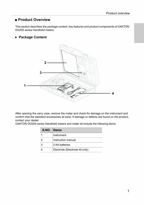
● Package Content
After opening the carry case, remove the meter and check for damage on the instrument and confirm that the standard accessories all exist. If damage or defects are found on the product, contact your dealer.OAKTON DO200 series Handheld meters and meter kit include the following items:
S.NO. Name
1 Instrument
2 Instruction manual
3 2 AA batteries
4 Electrode (Electrode kit only)
4
1
3
2
1

Product overview
● Key Features
• IP67 water ingress, dust-proof, shock-resistant, anti-slip meter housing.• Large monochrome LCD (50 x 50 mm) with white LED back lighting.• Built-in electrode holder (up to 2 electrodes). • Foldable meter stand.• Simple user interface and single parameter display.• 500 (for DO250) / 1000 (for DO260) data memory.• Automatic Temperature Compensation (ATC) with temperature calibration.• Adjustable auto shut-off time (1 to 30 minutes).• Auto-hold / Auto stable / Real-time measurement modes with stability indicators.• Powered by 2 x AA batteries. • Real-time clock (only for DO260).• PC (standard USB) / Printer (25 pin serial) connection via 2.5 mm diameter phono jack.
2

Product overview
● Product components
No Name Function
1 Monochrome LCD Displays the measured value
2 Operation keys Used for instrument operation
3 Electrode connector Connect to the BNC connector of the electrode
4 Temperature connector (T) Connect to the temperature sensor of the electrode
5 Battery cover Open/close to insert/remove batteries
6 Electrode holder Hold the electrode to carry with the instrument
7 Meter standOpen stand to place the meter at an inclined position on a flat surface
8 Serial connector Connects to the PC or printer with the appropriate cable
3

Product overview
● Display
No Name Function
1 Status IconDisplays the current operation mode (Setup, Calibration, Measurement and Data mode)
2 Parameters Displays the measured parameters like DO
3Stability indicator shows value is stable for the documentation in auto-stable and auto-hold modes
4Appears when the measured value display is stable and fixed in auto-hold mode
5Temperature display area
Displays the measured temperature
6Measured value, set item display area
Displays the measured value and the set value
7
Indicates electrode sensitivity level
8 Indicate error situations
9 Indicates data being transfered to the printer or computer
10 Displays the unit for the measurement parameter
11 Displays the battery level
4

Product overview
● Battery level display
● Electrode sensitivity level
100% battery life
50% battery life
20% battery life
Batteries are weak and need replacement. Refer “BATT LOW” on page 39 to solve this
Electrode sensitivity 80% (excellent)
Electrode sensitivity between 80% to 60% (very good)
Electrode sensitivity between 60% to 50% (good). Refer “SLPE ERR” on page 39 to solve this
5

Product overview
● Keypad operation
Keypad operation
Name Function
CAL keySwitches from the measurement mode to the calibration mode. Starts calibration in the calibration mode.
MEAS keySwitches from the operation mode to the measurement mode. Releases the fixed measurement value mode in the auto hold mode and begins a new measurement.
DATA key Switches from the measurement mode to the data mode.
MODE key In the measurement mode, changes measurement parameters.
SET keySwitches from the measurement mode to the setup mode.
ENTER keyDetermines the selection or setup.Saves data in the measurement mode and calibration mode.
UP key In the setup mode, navigates between the setup.Selects preferred option in some setup screens.Increases or decreases selected digit when entering numbers.
DOWN key
POWER key Powers ON/OFF the instrument.
6

Basic operations
■ Basic operations
This section describes function and basic operation method of each part of OAKTON DO200 series Handheld meters.
● Turning on the instrument
Inserting the batteries
This instrument is operated by batteries. You can use AA alkaline batteries or AA Ni- MH chargeable batteries. Perform the following procedure to insert batteries in the instrument.
1. Unscrew the battery cover on the back of the instrument counter-clock wise to unlock the bat-tery cover.
2. Remove the battery cover and set the batteries inside.
3. Replace battery cover.
4. Screw the battery cover on the back of the instrument clockwise to lock the battery cover.
• Do not replace the batteries in a dusty place or with wet hands. Dust or moisture could getinside the instrument and possibly cause an instrument malfunction.
• Do not short-circuit a battery.• Note polarity as shown in the battery compartment.• When the battery has depleted or the instrument will not be used for a long time, remove
the batteries.• Of the specified battery types, make sure to use two batteries of the same type.• Do not use a new battery together with an used battery.
Note
7

Basic operations
● Connecting an electrode
To perform calibration / measurement, it is necessary to use the appropriate electrode for measurement parameter. Use the following procedure to correctly connect the electrode to the instrument.
1. Insert the electrode connector by fitting its groove with the connector pin of the instrument.
2. Turn the electrode connector clockwise by following the grooves.3. Slide the connector cover on the connector.4. When using a combination electrode equipped with a temperature sensor, insert the
temperature jack (T) to the ATC socket on the meter.
Electrode connector
Temperature jack (T)
8

Basic operations
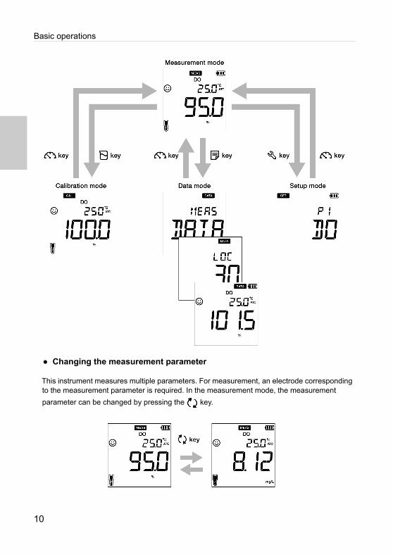
● Mode and measurement
● Changing the operation mode
You can change the operation mode to four available modes depending on the purpose of use. The status icon indicates the current mode.
You can change the operation mode using the corresponding key:
• Measurement mode: Press the key to change to the measurement mode.
• Calibration mode: In the measurement mode, press the key to change to the
calibration mode.
• Data mode: In the measurement mode, press the key to change to the data mode.
• Setup mode: In the measurement mode, press the key to change to the setup mode.
Icon Name Function
Setup mode Perform various setup functions.
Calibration mode Performs calibration.
Measurement mode
Performs measurement.
Data mode Performs data setup. Displays the saved data.
9
Basic operations
● Changing the measurement parameter
This instrument measures multiple parameters. For measurement, an electrode corresponding to the measurement parameter is required. In the measurement mode, the measurement
parameter can be changed by pressing the key.
10

DO calibration
● Calibration
This section describes the basic calibration method using OAKTON DO200 series Handheld meters and DO electrode.
● DO Calibration
Calibration is necessary for accurate dissolved oxygen measurement. Two calibration modes are available in DO meter for calibration,• Saturated oxygen concentration mode (%)• Dissolved oxygen measurement mode (mg/L)
To perform various DO calibrations, follow the procedures detailed below:
Set the air pressure value (default setup is 101.3 kPa) before calibration for accurate measurement.
● Calibration in saturated oxygen concentration mode (%)
Prerequisites
• Clean the membrane at the tip of the DO electrode with DI (deionized) water and wipe it with tissue paper.
• Switch on the DO meter and plug in the DO electrode.
• Press the key to keep the DO meter in saturated oxygen concentration mode (%) mode.
• Calibration performed in clean air is referred as air calibration.• Perform the air calibration in clean air at a location not subjected to dramatic temperature
change, rain or direct wind.• Do not hold the tip of DO electrode with hand during calibration, as the electrode may be
affected by temperature causing instability in calibration value.
To abort an ongoing calibration process at any point of time, press the key.
Note
Note
Tip
11
DO calibration
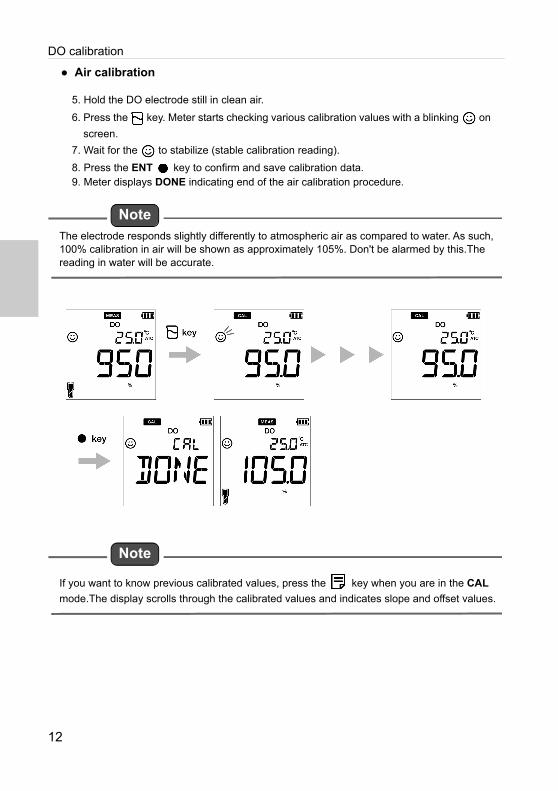
● Air calibration
5. Hold the DO electrode still in clean air.
6. Press the key. Meter starts checking various calibration values with a blinking on
screen.
7. Wait for the to stabilize (stable calibration reading).
8. Press the ENT key to confirm and save calibration data.9. Meter displays DONE indicating end of the air calibration procedure.
The electrode responds slightly differently to atmospheric air as compared to water. As such, 100% calibration in air will be shown as approximately 105%. Don't be alarmed by this.The reading in water will be accurate.
If you want to know previous calibrated values, press the key when you are in the CAL
mode.The display scrolls through the calibrated values and indicates slope and offset values.
Note
Note
12

DO calibration
● Zero calibration
1. Dip the DO electrode in the zero standard solution.
2. Press the key. Meter starts checking various calibration values with a blinking on
screen.
3. Wait for the to stabilize (stable calibration reading).
4. Press the key again to move to Zero Calibration mode.
5. Press the ENT key to confirm and save calibration data.6. Meter displays DONE indicating end of the zero calibration procedure.
• Calibration performed with zero standard solution is referred as zero calibration.• Prepare zero standard solution by adding 50 g of sodium sulfite (Na2SO3) to 1000 mL
deionized water and stirring the mixture to completely dissolve the Na2SO3.
Note
13

DO calibration
● Calibration in dissolved oxygen measurement mode (mg/L)
Prerequisites
• Clean the membrane at the tip of the DO electrode with DI (deionized) water and wipe it with tissue paper.
• Prepare required standard solutions (high-concentration and low-concentration solutions).• Switch on the DO meter and plug in the DO electrode.• Dip the DO electrode at least 6 cm in the standard solution.
• Press the key to keep the DO meter in dissolved oxygen measurement mode (mg/L) mode.
• Calibrate in the dissolved oxygen measurement mode in the order from high-concentration solution to a low-concentration solution.
• User can adjust the measured dissolved oxygen reading by calibration and the adjusted value is applied as an off set to the actual measurement.
• Prepare high-concentration solution by aerating a sample of fresh water for about 2 hours.
To abort an ongoing calibration process at any point of time, press the key.
Note
Tip
14

DO calibration
● 1st point calibration
1. After placing the DO electrode in the high concentration solution, press the key.
Meter starts checking various calibration values with a blinking on screen.
2. Wait for the to stabilize (stable calibration reading).
3. Use the keys to adjust the DO reading.
4. Press the ENT key to confirm and save calibration data.
5. Meter displays CAL DONE indicating end of the calibration procedure.
15
DO calibration
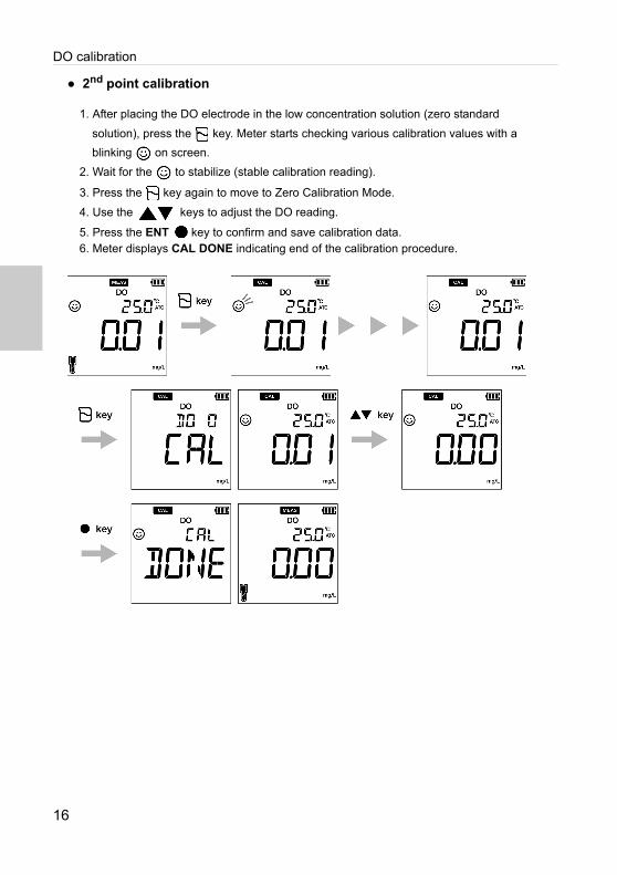
● 2nd point calibration
1. After placing the DO electrode in the low concentration solution (zero standard
solution), press the key. Meter starts checking various calibration values with a
blinking on screen.
2. Wait for the to stabilize (stable calibration reading).
3. Press the key again to move to Zero Calibration Mode.
4. Use the keys to adjust the DO reading.
5. Press the ENT key to confirm and save calibration data.6. Meter displays CAL DONE indicating end of the calibration procedure.
16

Temperature calibration
● Temperature Calibration
Temperature calibration is required to accurately match the DO electrode to the meter. Check the temperature reading and if its acceptable, no temperature calibration is required. If you need to calibrate, please follow the procedure detailed below:
Prerequisites
• Clean the DO electrode with DI (deionized) water and wipe it with tissue paper.• Switch on the DO meter and plug in the DO electrode and temperature sensor.• Dip the DO electrode in the standard solution till its temperature sensor is immersed.• Wait for 5 minutes to ensure temperature stability.
• Meter displays MTC if the temperature sensor is not plugged in and displays ATC if thetemperature sensor is plugged in.
• Temperature calibration must be performed using a known temperature solution or againsta calibrated thermometer.
To abort an ongoing calibration process at any point of time, press the key.
Note
Tip
17
Temperature calibration
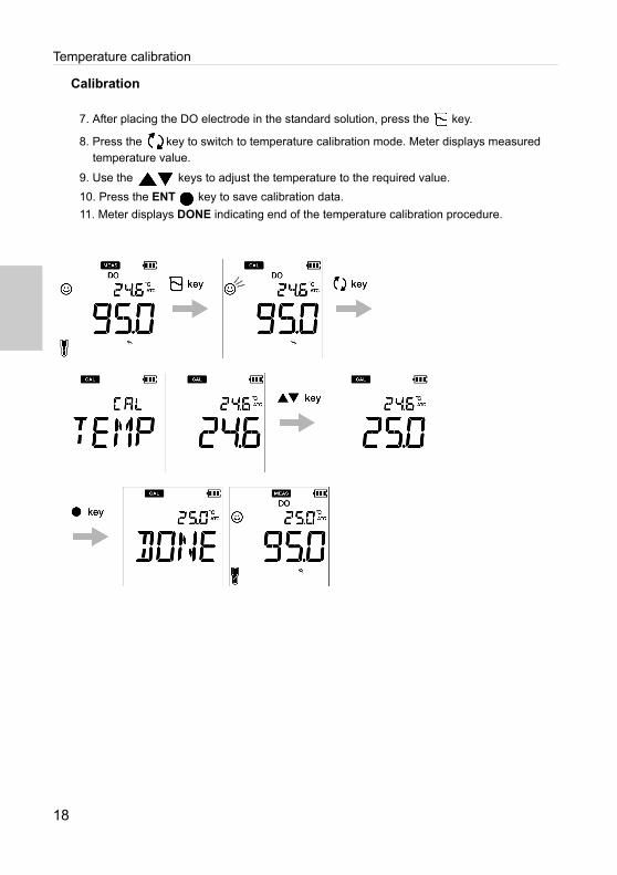
Calibration
7. After placing the DO electrode in the standard solution, press the key.
8. Press the key to switch to temperature calibration mode. Meter displays measured temperature value.
9. Use the keys to adjust the temperature to the required value.
10. Press the ENT key to save calibration data.
11. Meter displays DONE indicating end of the temperature calibration procedure.
18

Data capture and storage
■ Data
This section describes the basic method of data transferring using OAKTON DO200 series Handheld meters.
● Data capture and storage
In OAKTON DO200 series Handheld meters DO200, data measured by the instrument can be stored in the internal memory. To save the measured data:
• Press the ENT key to save the displayed data.• Meter displays the saved data for 2 seconds and then the display returns to the previous
screen automatically.
• If the data storage limit reaches 500 in DO250 model or 1000 in DO260 model, memory full error occurs and MEM FULL is displayed.
• In such case, print the data or transfer necessary data to a PC (only for DO260) and delete the data from the internal memory of the instrument.
Viewing stored data
• To view stored data, press key .
• Use keys to review different stored records.
• Press key to return to measurement mode.
Note
19

Data capture and storage
● Data transfer
● Transfer data to PC
Connect the instrument to a PC using the phono plug to USB cable to transfer saved data to the PC (for OAKTON DO200 series Handheld meters). Connect the phono jack at the instrument side to the communication port on the PC.
● Print data
To print a desired data set:
12. When the instrument is in the measurement mode, press key.
13. Use keys to view desired stored data.
14. Press key to print that individual data.
● Printer format- measurement
To print entire stored data log, refer “P2.2 Print data setup” on page 27.
Meter Model : OAKTON DO200
Serial Number : 123456789
SW Revision : 1.00
Date : 20 Aug 2018
Time : 10:10:28
Mode : DO
DO : 100.0 %
Temperature : 25.0 C (MAN)
Electrode Status : Excellent
User Name :
Signature :
Tip
20
DO set up
■ Setup
This section describes all the setup functions available in OAKTON DO200 series Handheld meters DO200.
● P1 DO setup
Using P1 DO setup function of the meter, you can: • Set salinity value• Set barometric pressure• Erase calibration dataTo set the DO functions using OAKTON DO200 series Handheld meters, follow the procedure detailed below:
Prerequisites
Switch on the DO meter.
• Default salinity value is 0.0 ppt. You can set a value in between 0.0 to 40.0 ppt.• Default barometric pressure is 101.3 kPa. You can set a value in between 10.0 to 200.0 kPa.• Erasing previous calibration data is recommended for accurate calibration. Default setup is
NO but to erase the calibration data, you need to change the setup to YES.
To return to the measurement mode, press the key.
Note
Tip
21

DO set up
● P1.1 Salinity value setup
15. Press the key, P1 DO screen appears.
16. Press the ENT key, P1.1 SAL screen appears.
17. Press the ENT key, by default SAL 0.0 ppt appears.
18. Use the keys to adjust the salinity value in between 0.0 to 40.0 ppt.
19. Press the ENT key, P1.1 SAL screen appears. This indicates completion of salin-
ity value setup.
22

DO set up
● P1.2 Barometric pressure setup
1. Press the key, P1 DO screen appears.
2. Press the ENT key, P1.1 SAL screen appears.
3. Press the key, P1.2 PRES screen appears.
4. Press the ENT key, by default PRES 101.3 appears.
5. Use the keys to adjust the barometric pressure in between 10.0 to 200.0 kPa.
6. Press the ENT key, P1.2 PRES screen appears. This indicates completion of barometric pressure setup.
23

DO set up
● P1.3 Erase calibration data
1. Press the key, P1 DO screen appears.
2. Press the ENT key, P1.1 SAL screen appears.
3. Press the key, P1.2 PRESS screen appears.
4. Press the key, P1.3 C.CLr appears.
5. Press the ENT key, C.CLr NO screen appears with NO as default setup.
6. Use the keys to change the setup to YES. This erases the calibration data.
7. Press the ENT key. P1.3 C.CLr screen appears. This indicates erasure of
calibration data.
24

Data set up
● wP2 Data setup
Using P2 Data setup function of the meter, you can: • Set data log interval• Print data log• Erase data log To set the data functions using OAKTON DO200 series Handheld meters, follow the procedure detailed below:
Prerequisites
Switch on the DO meter.
Data log interval can be set from 2 to 999 seconds.
To return to the measurement mode, press the key.
Note
Tip
25

Data set up
● P2.1 Data log interval setup
8. Press the key, P1 DO screen appears.
9. Press the key, P2 DATA screen appears.
10. Press the ENT key, P2.1 LOG screen appears.
11. Press the ENT key, previously set log interval appears.
12. Use the keys to set the data log interval.
13. Press the ENT key, P2.1 LOG screen appears. This indicates completion of data log interval setup.
.
26

Data set up
● P2.2 Print data setup
1. Press the key, P1 DO screen appears.
2. Press the key, P2 DATA screen appears.
3. Press the ENT key, P2.1 LOG screen appears.
4. Press the key, P2.2 PrNT screen appears.
5. Press the ENT key, default setup is NO.
6. Use the keys to change the setup to YES.
7. Press the ENT key, P2.2 PrNT screen appears. This indicates completion of the print data.
27
Data set up
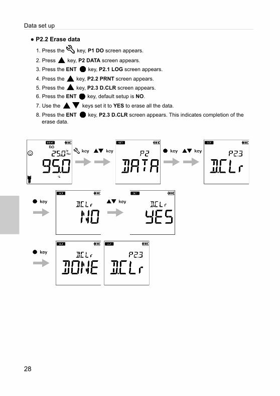
● P2.2 Erase data
1. Press the key, P1 DO screen appears.
2. Press key, P2 DATA screen appears.
3. Press the ENT key, P2.1 LOG screen appears.
4. Press the key, P2.2 PRNT screen appears.
5. Press the key, P2.3 D.CLR screen appears.
6. Press the ENT key, default setup is NO.
7. Use the keys set it to YES to erase all the data.
8. Press the ENT key, P2.3 D.CLR screen appears. This indicates completion of the erase data.
28
General set up
● P3 General setup
Using P3 General setup function of the meter, you can: • Select stability mode of the meter • Set auto shut-off time• Select temperature measurement • Reset the meter To set the general functions using OAKTON DO200 series Handheld meters, follow the procedure detailed below:
Prerequisites
Switch on the DO meter.
• In the calibration mode, the auto stable (AS) mode is activated. Default stability setup inmeasurement mode is “auto stable” (AS). You can change it to “auto hold” (AH) or “realtime” (RT).
• Default auto shut-off time is 30 minutes. You can set the time from ---- to 30 minutes, where ---- indicates “no auto shut-off time” has been set and meter will be on continuously.
• Default temperature unit is °C and you can change the unit to °F.• Default reset meter setup is NO. If you like to reset the meter, you can change it to YES.
• Stability judgment criteria remains same for both auto stability mode and auto hold mode.
• To return to the measurement mode, press the key.
Note
Tip
29

General set up
● P3.1 Auto Stable, Auto Hold and Real Time mode setup
Auto Stable (AS) mode - the meter shows live readings annunciator blinks until the reading is stable.
Auto Hold (AH) mode - the meter locks the stable reading; annunciator blinks until reading is
stable and then lights up.
Real Time (RT) mode - the meter shows live readings; Both and annunciators are inactive.
9. Press the key, P1 DO screen appears.
10. Press key, P2 DATA screen appears.
11. Press key, P3 GEN screen appears.
12. Press the ENT key, P3.1 STBL screen appears.
13. Press the ENT key, Default the stability mode is AS (auto stable).
14. Use the keys to change the stability mode as AH (auto hold) or RT (real time).
15. Press the ENT key, P3.1 STBL screen appears. This indicates completion of the stability mode selection.
30

General set up
● P3.2 Auto shut-off time setup
1. Press the key, P1 DO screen appears.
2. Press the key, P2 DATA screen appears.
3. Press the key, P3 GEN screen appears.
4. Press the ENT key, P3.1 STBL screen appears.
5. Press the key, P3.2 A.OFF screen appears.
6. Press the ENT key, default auto shut-off time is 30 minutes.
7. Use the keys to adjust the auto off time.
8. Press the ENT key, P3.2 A.OFF screen appears. This indicates completion of the
auto shut-off time setup.
The default shut off time is 30 minutes. This can be adjusted from 1 minute to 30 minutes. If you set the display to ‘----’ it indicates Auto Off is disabled. Meter will be on indefinitely till the user switches off the meter.
Note
31
General set up
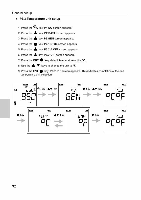
● P3.3 Temperature unit setup
1. Press the key, P1 DO screen appears.
2. Press the key, P2 DATA screen appears.
3. Press the key, P3 GEN screen appears.
4. Press the key, P3.1 STBL screen appears.
5. Press the key, P3.2 A.OFF screen appears.
6. Press the key, P3.3°C°F screen appears.
7. Press the ENT key, default temperature unit is °C.
8. Use the keys to change the unit to °F.
9. Press the ENT key, P3.3°C°F screen appears. This indicates completion of the end temperature unit selection.
32
General set up
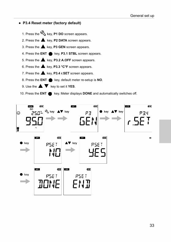
● P3.4 Reset meter (factory default)
1. Press the key, P1 DO screen appears.
2. Press the key, P2 DATA screen appears.
3. Press the key, P3 GEN screen appears.
4. Press the ENT key, P3.1 STBL screen appears.
5. Press the key, P3.2 A.OFF screen appears.
6. Press the key, P3.3 °C°F screen appears.
7. Press the key, P3.4 r.SET screen appears.
8. Press the ENT key, default meter re-setup is NO.
9. Use the key to set it YES.
10. Press the ENT key. Meter displays DONE and automatically switches off.
33

Clock set up
● P4 CLK setup
Real-time clock functionality is available only for OAKTON DO200 series Handheld meters. Using P4 Clock setup function of the meter, you can set:• Date • TimeTo set the clock function using OAKTON DO200 series Handheld meters, follow the procedure detailed below:
Prerequisites
Switch on the DO meter.
• Setup date and time is necessary before using the instrument for the first time or afterreplacing the batteries.
• Set date and time data is captured correctly while saving data in the internal memory.
To return to the measurement mode, press the key.
Note
Tip Tip
34
Clock set up
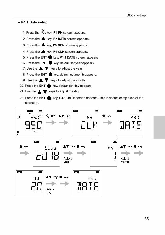
● P4.1 Date setup
11. Press the key, P1 PH screen appears.
12. Press the key, P2 DATA screen appears.
13. Press the key, P3 GEN screen appears.
14. Press the key, P4 CLK screen appears.
15. Press the ENT key, P4.1 DATE screen appears.
16. Press the ENT key, default set year appears.
17. Use the keys to adjust the year.
18. Press the ENT key, default set month appears.
19. Use the keys to adjust the month.
20. Press the ENT key, default set day appears.
21. Use the keys to adjust the day.
22. Press the ENT key, P4.1 DATE screen appears. This indicates completion of the
date setup.
35
Clock set up
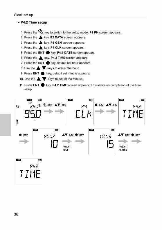
● P4.2 Time setup
1. Press the key to switch to the setup mode, P1 PH screen appears.
2. Press the key, P2 DATA screen appears.
3. Press the key, P3 GEN screen appears.
4. Press the key, P4 CLK screen appears.
5. Press the ENT key, P4.1 DATE screen appears.
6. Press the key, P4.2 TIME screen appears.
7. Press the ENT key, default set hour appears.
8. Use the keys to adjust the hour.
9. Press ENT key, default set minute appears.
10. Use the keys to adjust the minute.
11. Press ENT key, P4.2 TIME screen appears. This indicates completion of the time setup.
36

Maintenance and storage
37
■ Maintenance and storage
This section describes maintenance of OAKTON DO200 series Handheld meters, DO electrodes used with the meter.
● Maintenance Contract
Please contact your dealer for the product maintenance contract.
● Maintenance and storage of the instrument
● How to clean the instrument
• If the instrument is dirty, wipe it gently with a soft dry cloth. If it is difficult to remove the dirt,wipe it gently with a cloth moistened with alcohol.
•The instrument is made of solvent resistant materials but is not resistant to all chemicals.Donot dip the instrument in strong acid or alkali solution, or wipe it with such solutions.
• Do not wipe the instrument with polishing powder or other abrasive compound.
● Environmental conditions for storage
• Temperature: 0 °C to 45 °C• Humidity: under 80% relative humidity and free from condensation
● Avoid the following conditions
• Dusty place• Strong vibration• Direct sunlight • Corrosive gas environment• Close to an air-conditioner• Direct wind
Maintenance and storage
38
● Maintenance and storage of the DO electrode
This section describes an overview of the procedures for maintenance and storage of DO electrode to be performed as part of daily use.
● How to clean the membrane of DO electrode
The membrane of DO electrode is extremely thin. Take care, not to tear the membrane when cleaning. Clean the membrane with deionized water and wipe it with a soft cloth, take care not to damage it.
When using a neutral cleaning solution to clean the DO electrode, keep the neutral cleaning solution away from the membrane in order to prevent deterioration of the membrane.
● Daily storage of the DO electrode
Follow the steps below to store the electrode correctly. 9552-20D, 9552-50D
12. Clean the DO electrode well with deionized water.13. Store electrode in carry case in a dry condition.
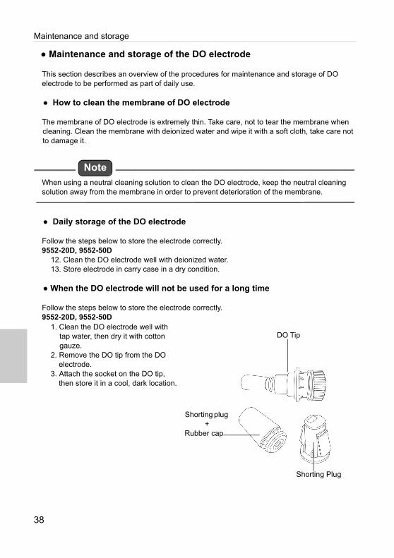
● When the DO electrode will not be used for a long time
Follow the steps below to store the electrode correctly.9552-20D, 9552-50D
1. Clean the DO electrode well with tap water, then dry it with cotton gauze.
2. Remove the DO tip from the DO electrode.
3. Attach the socket on the DO tip, then store it in a cool, dark location.
Note
DO Tip
Shorting plug +
Rubber cap
Shorting Plug

Error messages and trouble shooting
■ Error messages and trouble shooting
● Error message
This section describes the causes of typical errors and the actions to be taken to resolve respective errors.
If ERR is displayed while you are using the instrument, check the error, its cause and action to be taken in the error list below:
Meter display ERR description Cause of errorand
How to solve the problem
BATT LOW Low batteryBattery power is low. Please replace with new batteries.
OFFS ERR Offset voltage error Electrode is dirty. Clean the electrode.
SLPE ERR Slope errorElectrode sensitivity is low. Please clean and recalibrate. If the problem persists, replace the electrode with new one.
STD ERRCan not auto recognize standard solution
The instrument cannot identify the standard solution. Check the calibration solution and use fresh one if required.
Calibration interval alarm error
Exceeds the calibration interval setup. Calibrate the meter.
MEM FULLMemory data full
The number of the data saved has exceeded the specified number of items. Print or transfer the data. Or, clear stored data.
If user selects the enter key before stable in calibration mode
key is pressed before the calibration value has stabilized. Wait for the value to be stable
and then press the key.
39

Error messages and trouble shooting
● Trouble shooting
This section describes causes and actions to take for problems that customers frequently ask. The indicated value fluctuates< Problem with the electrode >
< Problem with the instrument >
The response is slow
Cause How to solve problem
The electrode is dirty. Clean the electrode.
The electrode is broken. Replace the electrode.
Cause How to solve problem
There is a motor or other device causing electrical interference.
Measure at a place where no influence from induction is given. Ground all AC-powered equipment.
The electrode is not connected correctly.
Connect the electrode properly.
Cause How to solve problem
The electrode is dirty. Clean the electrode.
The electrode is broken. Replace the electrode.
40
Error messages and trouble shooting
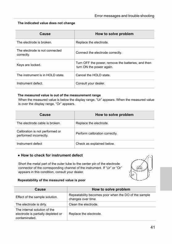
The indicated value does not change
The measured value is out of the measurement rangeWhen the measured value is below the display range, “Ur” appears. When the measured value is over the display range, “Or” appears.
● How to check for instrument defect
Short the metal part of the outer tube to the center pin of the electrode connector of the corresponding channel of the instrument. If “Ur” or “Or” appears in this condition, consult your dealer.
Repeatability of the measured value is poor
Cause How to solve problem
The electrode is broken. Replace the electrode.
The electrode is not connected correctly.
Connect the electrode correctly.
Keys are locked.Turn OFF the power, remove the batteries, and then turn ON the power again.
The instrument is in HOLD state. Cancel the HOLD state.
Instrument defect. Consult your dealer.
Cause How to solve problem
The electrode cable is broken. Replace the electrode.
Calibration is not performed or performed incorrectly.
Perform calibration correctly.
Instrument defect Check as explained below.
Cause How to solve problem
Effect of the sample solution.Repeatability becomes poor when the DO of the sample changes over time.
The electrode is dirty. Clean the electrode.
The internal solution of the electrode is partially depleted or contaminated.
Replace the electrode.
41

Error messages and trouble shooting
Nothing appears when the power is turned ON
Swelling of keypad
Part of the display is missing
Cause How to solve problem
Power is not supplied. Insert batteries.
Battery polarity (+, ) is reversed.Insert the batteries with the polarity (+, ) correctly oriented.
Battery life is low. Replace the batteries.
Instrument defect Consult your dealer.
Cause How to solve problem
Using the instrument at high elevation or other location where the air pressure is different from sea level.
To eliminate the pressure difference between the inside and outside of the instrument, briefly open and then close the serial connector cover and battery cover. After opening, correctly close the cover to maintain dust and water proofing.
Instrument defect Consult your dealer.
Cause How to solve problem
Instrument defectCheck the display by switching ON the instrument when all the LCD segments are lit.
42

Technical note
43
■ Appendix
● Appendix 1
This section describes technical information and option for OAKTON DO200 series Handheld meters.
● Saturated DO levels in water at various temperatures
ISO17289 (JIS K0102)
Temp.(°C)
SaturatedDO(mg/L)
Temp.(°C)
SaturatedDO(mg/L)
Temp.(°C)
SaturatedDO(mg/L)
Temp.(°C)
SaturatedDO(mg/L)
1 14.22 11 11.03 21 8.92 31 7.43
2 13.83 12 10.78 22 8.74 32 7.31
3 13.46 13 10.54 23 8.58 33 7.18
4 13.11 14 10.31 24 8.42 34 7.07
5 12.77 15 10.08 25 8.26 35 6.95
6 12.45 16 9.87 26 8.11 36 6.84
7 12.14 17 9.67 27 7.97 37 6.73
8 11.84 18 9.47 28 7.83 38 6.62
9 11.56 19 9.28 29 7.69 39 6.52
10 11.29 20 9.09 30 7.56 40 6.41
Printout summary
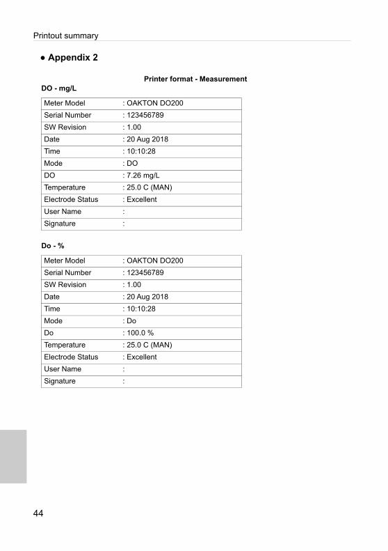
● Appendix 2
Printer format - MeasurementDO - mg/L
Do - %
Meter Model : OAKTON DO200
Serial Number : 123456789
SW Revision : 1.00
Date : 20 Aug 2018
Time : 10:10:28
Mode : DO
DO : 7.26 mg/L
Temperature : 25.0 C (MAN)
Electrode Status : Excellent
User Name :
Signature :
Meter Model : OAKTON DO200
Serial Number : 123456789
SW Revision : 1.00
Date : 20 Aug 2018
Time : 10:10:28
Mode : Do
Do : 100.0 %
Temperature : 25.0 C (MAN)
Electrode Status : Excellent
User Name :
Signature :
44

Printout summary
Printer format - Data log
Meter Model : OAKTON DO200
Serial Number : 123456789
SW Revision : 1.00
User Name :
Signature :
Logged Data
Location : 2
Date : 10 Aug 2018
Time : 10:10:28
Mode : pH
pH : 7.00 pH
mV : 0.0 mV
Temperature : 25.0 C (MAN)
Electrode Status : Excellent
Location : 1
Date : 10 Aug 2018
Time : 10:09:28
Mode : mV
mV : 178.0 mV
Temperature : 25.0 C (MAN)
45

Printout summary
Printer format - CalibrationDO (%)
DO (mg/L)
Meter Model : OAKTON DO200
Serial Number : 123456789
SW Revision : 1.00
Date : 20 Aug 2018
Time : 10:10:28
Cal Points : 100.0 %, 0.0 %
Span. Coef : 1.23
Zero. Coef : 0.12
Cal Temp. : 25.0 C (ATC)
Electrode Status : Excellent
User Name :
Signature :
Meter Model : OAKTON DO200
Serial Number : 123456789
SW Revision : 1.00
Date : 20 Aug 2018
Time : 10:10:28
Cal Points : 8.26 mg/L, 0.0 mg/L
Span. Coef : 1.23
Zero. Coef : 0.12
Cal Temp. : 25.0 C (ATC)
Electrode Status : Excellent
User Name :
Signature :
46

Specifications
● Appendix 3
ModelDO250 DO260
DO/Temp (°C/°F)
Dissolved Oxygen (DO) Range 0.0 to 20.00 mg/L0.0 to 200.0%
Resolution 0.01 mg/L, 0.1%
Accuracy ±0.1 mg/L
Salinity Compensation 0.0 to 40.0 ppt
Barometric Pressure Compensation Yes
DO Probe Type Galvanic integrated with temperature sensor
Calibration Points Up to 2
Temperature Range -30.0 to 130.0 °C / -22.0 to 266.0 °F
Resolution 0.1 °C / °F
Accuracy ± 0.5 °C / ± 0.9 °F
Calibration Option Yes
Memory 500 1000
Auto Data Log
Real-time Clock -
Date & Time Stamp -
Auto Hold / Auto Stable / Real Time
Auto Shut-Off (1 to 30 mins.)
Electrode Status
Diagnostic Messages
Software Upgrade1
PC Communication1 -
Printer Communication2 -
Meter Inputs BNC, phono
Display Custom LCD with backlight
Housing IP67, shock & resistant, non-slip
Power Requirement 2 × AA batteries
Battery Life > 500 hours
Dimensions 160 (L) × 80 (W) × 40.60 (H) mm
WeightApprox. 260 g (with batteries) /
216 g (without batteries)
47

Specifications
48

625 East Bunker Court, Vernon Hills, IL, 60061, USATel : 1-888-462-5866Fax: [email protected]
For any questions regarding this product, please contact your local agency
Oakton Instruments