DNV-RP-C301: Design, Fabrication, Operation and ... · PDF file1.2 Structure of RP ......
62
RECOMMENDED PRACTICE DET NORSKE VERITAS AS The electronic pdf version of this document found through http://www.dnv.com is the officially binding version DNV-RP-C301 Design, Fabrication, Operation and Qualification of Bonded Repair of Steel Structures APRIL 2012
Transcript of DNV-RP-C301: Design, Fabrication, Operation and ... · PDF file1.2 Structure of RP ......

RECOMMENDED PRACTICE
The electronic
DNV-RP-C301
Design, Fabrication, Operation and Qualification of Bonded Repair
of Steel StructuresAPRIL 2012
DET NORSKE VERITAS AS
pdf version of this document found through http://www.dnv.com is the officially binding version

FOREWORD
DET NORSKE VERITAS (DNV) is an autonomous and independent foundation with the objectives of safeguarding life,property and the environment, at sea and onshore. DNV undertakes classification, certification, and other verification andconsultancy services relating to quality of ships, offshore units and installations, and onshore industries worldwide, andcarries out research in relation to these functions.
DNV service documents consist of among others the following types of documents:— Service Specifications. Procedual requirements.— Standards. Technical requirements.— Recommended Practices. Guidance.
The Standards and Recommended Practices are offered within the following areas:A) Qualification, Quality and Safety MethodologyB) Materials TechnologyC) StructuresD) SystemsE) Special FacilitiesF) Pipelines and RisersG) Asset OperationH) Marine OperationsJ) Cleaner Energy
O) Subsea Systems
© Det Norske Veritas AS April 2012
Any comments may be sent by e-mail to [email protected]
This service document has been prepared based on available knowledge, technology and/or information at the time of issuance of this document, and is believed to reflect the best ofcontemporary technology. The use of this document by others than DNV is at the user's sole risk. DNV does not accept any liability or responsibility for loss or damages resulting fromany use of this document.

Recommended Practice DNV-RP-C301, April 2012Changes – Page 3
CHANGES
General
This is a new document.
Acknowledgement
This Recommended practice is based upon a project guideline developed within the Joint Industry Project“Qualification of adhesive bonding in structural repairs of FPSO's”. The following companies sponsored this JIP:
— ConocoPhillips— Norsk Hydro— Petrobras (CENPES)— PETRONAS Research and Scientific Services— Shell (Enterprise Oil)— Statoil
DNV is grateful for valuable discussions and the fruitful co-operations with these companies. The companyindividuals are hereby acknowledged for their contribution.
In addition DML, Devonport Royal Dockyard Ltd., and Umoe Mandal AS have provided services to the JIP.The contributions provided by the Advisory Committee and by DML and by Umoe Mandal are gratefullyacknowledged.
DET NORSKE VERITAS AS

Recommended Practice DNV-RP-C301, April 2012Contents – Page 4
CONTENTS
1. Introduction............................................................................................................................................ 61.1 Objective and scope ..................................................................................................................................61.2 Structure of RP..........................................................................................................................................71.3 Relationship to other Codes ......................................................................................................................71.4 Requirements to documentation ...............................................................................................................71.5 Definitions.................................................................................................................................................81.6 Abbreviations............................................................................................................................................81.7 Symbols.....................................................................................................................................................81.8 Normative References...............................................................................................................................91.9 Other References.....................................................................................................................................102. Requirements........................................................................................................................................ 122.1 Criticality assessment and repair decision making .................................................................................122.2 Examples.................................................................................................................................................143. Pt.2 Repair Philosophy and Design Format ..................................................................................... 153.1 Introduction.............................................................................................................................................153.2 Definitions...............................................................................................................................................153.3 Design format..........................................................................................................................................164. Design Basis .......................................................................................................................................... 184.1 Purpose....................................................................................................................................................184.2 General ...................................................................................................................................................184.3 Loads and Boundary Conditions.............................................................................................................194.4 Environments (Chemicals, Temperature) ...............................................................................................204.5 Special Considerations for Repair Preparation .......................................................................................215. Failure Mechanisms and Design Criteria .......................................................................................... 235.1 General....................................................................................................................................................235.2 Failure modes and failure mechanisms...................................................................................................245.3 Design criteria.........................................................................................................................................245.4 Safety factors ..........................................................................................................................................266. Analysis Methodology.......................................................................................................................... 276.1 General....................................................................................................................................................276.2 Loads and load effects ............................................................................................................................276.3 Models of bonded repair failure mechanisms.........................................................................................297. Materials ............................................................................................................................................... 317.1 General....................................................................................................................................................317.2 Substrate..................................................................................................................................................317.3 Adhesives................................................................................................................................................317.4 Composite Materials ...............................................................................................................................32
8. Qualification Testing ........................................................................................................................... 338.1 General....................................................................................................................................................338.2 Characterisation of bondline properties – General ................................................................................338.3 Characterisation of laminates and metals ...............................................................................................348.4 Component testing ..................................................................................................................................34
9. Fabrication Procedures and Quality Assurance ............................................................................... 369.1 General....................................................................................................................................................369.2 Substrate – Surface preparation ..............................................................................................................369.3 Patch fabrication .....................................................................................................................................369.4 Adhesive Bonding...................................................................................................................................399.5 Personnel.................................................................................................................................................4010. In-service Inspection............................................................................................................................ 4110.1 General....................................................................................................................................................4110.2 Inspection strategy ..................................................................................................................................4110.3 Inspection of the metal substrate.............................................................................................................4210.4 Inspection of bondline.............................................................................................................................4210.5 Inspection of patch laminate ...................................................................................................................43Appendix A. Survey Procedures .................................................................................................................. 44
Appendix B. Criticality Assessment of the Damage................................................................................... 45
Appendix C. Checklist for Repair and Criticality Assessment................................................................. 46
Appendix D. List of Required Documents for Approval of Bonded Patch Repairs ............................... 47
DET NORSKE VERITAS AS

Recommended Practice DNV-RP-C301, April 2012Contents – Page 5
Appendix E. Determination of Formula for Debond Length due to Fatigue .......................................... 49
Appendix F. (Informative) Screening Tests................................................................................................ 50
Appendix G. Crack-Patched Beam Shear Fracture Test .......................................................................... 51
Appendix H. Patched Beam Edge Fracture Test ....................................................................................... 54
Appendix I. Double Strap Shear Fracture Test ......................................................................................... 56
Appendix J. Double Strap Edge Fracture Test .......................................................................................... 58
Appendix K. Blister Fracture Resistance Test ........................................................................................... 60
Appendix L. Idealised Fracture Toughness Tests ...................................................................................... 61
DET NORSKE VERITAS AS

Recommended Practice DNV-RP-C301, April 2012Sec.1. Introduction – Page 6
1. Introduction
1.1 Objective and scope
The main objectives of this Recommended Practice (RP) are to:
— provide an accepted industry practice for using bonded repair— serve as a technical reference document in contractual matters.
This RP provides:
— An assessment and decision making process on whether to proceed with a bonded patch repair. — A design and qualification process to design and fabricate bonded patches.
The scope of this RP covers design, materials, structural analysis, fabrication, testing, in-service inspection andmaintenance of bonded repairs. Aspects relating to documentation, verification and quality control are alsoaddressed.
Guidance note:
A repair might be rehabilitation of fatigue cracks in a structural element or bridging of cracks in corroded (structuralor non-structural) tank plating.
Furthermore, this technology could be used for modification or upgrading by reinforcing structural elements toprovided added capacity.
---e-n-d---of---G-u-i-d-a-n-c-e---n-o-t-e---
The repair procedures covered by this RP utilizes patches of composite material, steel or other structuralmaterials that are bonded to an existing steel structure.
The principle of a bonded repair is shown in Figure 1-1. The original structure was designed for certain loads.A fatigue or corrosion damage reduces its capability and the structure needs repair. Instead of welding, a patchwill be applied to restore the integrity of the structure.
Figure 1-1Concept of the composite repair for cracks and corrosion thinning1
1 “Reprinted from Composites Part A: Applied Science and Manufacturing, 40, MCGEORGE, D., ECHTERMEYER, A. T., LEONG,K. H., MELVE, B., ROBINSON, M. & FISCHER, K. P, Repair of floating offshore units using bonded fibre composite materials. 17pages, Copyright (2009), with permission from Elsevier”
DET NORSKE VERITAS AS
Recommended Practice DNV-RP-C301, April 2012Sec.1. Introduction – Page 7
1.2 Structure of RPThe individual phases in the repair design are covered by the various sections as shown below:Part 1 – Decision making
— Section 1 contains general information, references and definitions. — Section 2 provides guidance on deciding whether to perform bonded repairs.
Part 2 – Technical provision
— Section 3 describes the safety and design philosophy.— Section 4 describes the required contents of the design basis.— Section 5 describes criteria for evaluation of failure mechanisms and capacity checks of the repaired
structure.— Section 6 provides guidance on modelling and analysis of the bonded repair.— Section 7 describes materials and bonding agents and points out special considerations for bonding of
patches onto steel substrates.— Section 8 provides recommendations for screening testing to aid material selection and patching process
improvements, material characterisation testing to obtain input data to theoretical models and componenttesting to directly demonstrate the performance of bonded repairs.
— Section 9 describes fabrication procedures and quality assurance including condition assessment andsurface preparation of the substrate.
— Section 10 gives guidance on in-service inspection and maintenance of the installed bonded repair.
1.3 Relationship to other CodesThis RP should be used in combination with the standards for design of steel offshore structures, denoted DNV-OS-C101 and DNV-OS-C102 or other applicable object standard (e.g. Ship Classification Rules), as well asthe standard for design of composite components, denoted DNV-OS-C501. This RP shall not be used as astand-alone document. Where reference is made to codes other than DNV documents, the valid revision shallbe taken as the revision that was current at the date of issue of this RP, unless otherwise noted, see Section 1.8.6.
1.4 Requirements to documentationThe documentation provided prior to installation of the repair shall include:
— A survey report of the damage providing information as specified in Appendix C.— A design report covering the design basis (see Section 4 for requirements) and the results of all design and
qualification activities in the bonded repair development shall be prepared. The design report forms thebasis for acceptance of the bonded repair by owner, operator and / or relevant authorities. The design reportshall document that all relevant information has been collected and all identified issues have been addressedin the design input, analysis, fabrication and qualification phases of the bonded repair process.
— An installation report shall be prepared by the repair contractor. — An in service inspection programme deemed appropriate for maintaining the integrity of the repair shall be
prepared.
Guidelines for the preparation of these reports can be found in Appendix D.
DET NORSKE VERITAS AS

Recommended Practice DNV-RP-C301, April 2012Sec.1. Introduction – Page 8
1.5 Definitions
1.6 Abbreviations
1.7 SymbolsThe Latin symbols in Table 1-2 and Greek symbols in Table 1-3 are used throughout this RP in combinationwith the indices in Table 1-1. These symbols are not always explained where they are used. Symbols not listedin these tables are explained whenever they are used.
Adherend Generic term used to denote a body or component attached to another by means of an adhesive. For bonded repairs both the patch and steel substrate are adherends.
Bondline The term bondline is used to designate the adhesive layer between the adherends as well as the interfaces between the adhesive and the adherend surfaces including surface preparation and primer layers if any.
Crack Herein, crack is used to denote a crack in the steel substrate that is to be repaired with bonded patches, see also debond. Sometimes the term substrate crack is used for clarity.
Critical elements Elements considered for repair in critical structural areas, i.e. areas that have been identified from calculations to require monitoring or from the service history of the subject vessel or unit or from similar or sister vessel or units to be sensitive to cracking, buckling or corrosion which would impair the structural integrity of the vessel or unit.
Debond Debond crack between the patch and the substrate. The term crack is not used with this meaning to avoid confusion with cracks in the substrate (those that are to be patch-repaired).
Non-critical elements structural elements that are not critical. Patch The adherend bonded to the steel substrate in order to repair it.Substrate The steel adherend onto which the patch is bonded in a bonded repair. Hence the term substrate
is used in a narrower sense than the term adherend.This RP Refers to this document, i.e. RP on Recommended Practice for Design, Fabrication, Operation and
Qualification of Bonded Composite Repair of Steel Structures
ASTM American Society for Testing and MaterialsFEA Finite Element AnalysisFEM Finite Element MethodFOU Floating Offshore UnitFRP Fibre-Reinforced PlasticsFPSO Floating Production Storage and Offloading unit.ISO International Organization for Standardization LRFD Load and Resistance Factor DesignNDI Non-Destructive InspectionRP Recommended PracticeSRA Structural Reliability Analysis
Table 1-1 Indicesc - central, i.e. referring to the position at the center of a patch bridging a crack or hole
- characteristicd - designe - edgep - patch
- plastics - substrate
Table 1-2 Latin Symbolsa - length of debond or crack (for internal cracks with two tips, the total length is by convention 2a)A - area, e.g. of a cross section
- proportionality constant in Paris’ law (substrate crack)C - proportionality constant in modified Paris’ law (debonding)D - beam flexural stiffness; equals E IE - Young’s modulus
- expected value of random variablef - axial force per unit width (F/w)F - axial force
- cumulative probability distributionG - shear modulus
DET NORSKE VERITAS AS
Recommended Practice DNV-RP-C301, April 2012Sec.1. Introduction – Page 9
1.8 Normative References
1.8.1 Revisions
The latest revisions of the referenced DNV documents apply.Guidance note:The latest revision of the DNV documents may be found in the publication list at the DNV web-site www.dnv.com - direct link: https://exchange.dnv.com/Publishing/Servicedocs.asp
---e-n-d---of---G-u-i-d-a-n-c-e---n-o-t-e---
1.8.2 DNV Offshore Standards
DNV-OS-C101: Design of Offshore Steel Structures, General (LRFD Method)
DNV-OS-C102: Structural Design of Offshore Ships
DNV-OS-C501: Composite Components.
1.8.3 DNV Recommended Practices
DNV-RP-C102: Structural Design of Offshore Ships.
DNV-RP-C203: Fatigue Strength Analysis of Offshore Steel Structures
DNV-RP-C205 Environmental Conditions and Environmental Loads.
1.8.4 DNV Classification Notes and Certification Notes
DNV Classification Note 30.1: Buckling Strength Analysis
DNV Classification Note 30.6: Structural Reliability Analysis of Ship Structures
DNV Classification Note 30.7: Fatigue Assessment of Marine Structures
DNV Classification Note 31.3: Strength Analysis of Hull Structures in Tankers.
1.8.5 DNV Rules
DNV Rules for Classification of Ships.
h - beam height- Weibull shape parameter
I - second moment of area J - fracture loading (energy release rate)k - axial stiffness, equals E Al - overlap lengthL - length; e.g. of beamm - slope parameter in Paris’ law (substrate crack)N - number of cyclesP - applied loadq - shear force per unit width (Q/w)
- Weibull scale parameterQ - shear forceR - fracture resistanceS - load effect (generic term for e.g. stress, strain, cross sectional force)t - thicknessT - timeU - elastic energyw - width; e.g. of patchW - work; e.g. by external forces or inelastic deformations
Table 1-3 Greek Symbolsε direct strainγ engineering shear strainμ slope parameter in modified Paris’ law (debonding)σ direct stressτ shear stress
Table 1-2 Latin Symbols
DET NORSKE VERITAS AS
Recommended Practice DNV-RP-C301, April 2012Sec.1. Introduction – Page 10
1.8.6 ISO and ASTM StandardsNote:The references are to the specific issues of the standards indicated.
---e-n-d---of---N-o-t-e---
ISO 2394:1998: General principles on reliability for structures.ISO 4587:2003 Adhesives -- Determination of tensile lap-shear strength of rigid-to-rigid bonded assemblies. ISO 15024:2001: Fibre-reinforced plastic composites -- Determination of mode I interlaminar fracturetoughness, GIC, for unidirectionally reinforced materials.ISO 11003-2: Adhesives -- Determination of shear behaviour of structural adhesives -- Part 2: Tensile testmethod using thick adherends.ISO/PDTS 24817 Petroleum, petrochemical and natural gas industries – Composite repairs for pipework –Qualification and design, installation testing and inspection, Working Draft, 2005-08-26.ASTM D3762-03 Standard Test Method for Adhesive-Bonded Surface Durability of Aluminum (Wedge Test).ASTM D3528-96 Standard Test Method for Strength Properties of Double Lap Shear Adhesive Joints byTension Loading (Covers metals, not FRP).ASTM D3846: Standard test method for in-plane shear strength of reinforced plastics.ASTM D3983: Standard test method for measuring strength and shear modulus of nonrigid adhesives bt thethick-adherend tensile-lap specimen.ASTM D5528-01 Standard Test Method for Mode I Interlaminar Fracture Toughness of Unidirectional Fibre-Reinforced Polymer Matrix Composites.ASTM D 5656-04, Test Method for Thick-Adherend Metal Lap-Shear Joints for Determination of the Stress-Strain Behavior of Adhesives in Shear by Tension Loading.ASTM D5868-01 Standard Test Method for Lap Shear Adhesion for Fibre Reinforced Plastic (FRP) Bonding.ASTM D6115-97(2004) Standard Test Method for Mode I Fatigue Delamination Growth Onset ofUnidirectional Fibre-Reinforced Polymer Matrix Composites.ASTM D6671/D6671M-04e1 Standard Test Method for Mixed Mode I-Mode II Interlaminar FractureToughness of Unidirectional Fibre Reinforced Polymer Matrix Composites.
1.9 Informative ReferencesIACS Guidelines for the Inspection and Maintenance of Double Hull Tanker Structures.IACS Guidance Manual for Tanker Structures.IACS Bulk Carriers Guidelines for Surveys, Assessment and Repair of Hull Structure.Hart-Smith L. J. “Adhesive-bonded double-lap joints”, NASA Report CR-112235, 1973.D. McGeorge, A. T. Echtermeyer, K. H. Leong, B. Melve, M. Robinson, and K. P. Fischer. Repair of floatingoffshore units using bonded fibre composite materials. Composites: Part A, 40:1364–1380, 2009.L. C. M. Meniconi, I. N. Porcincula, D. McGeorge, and A. Pedersen. Structural repair at a production platformby means of a composite material patch. In Proceedings of the Offshore Technology Conference. Houston,Texas, USA, 2010.S. Hashim, J. Nisar, N. Tsouvalis, K. Anyfantis, P. Moore, I. Chirica, C. Berggren, A. Orsolini, A. Quispitupa,D. McGeorge, B. Hayman, S. Boyd, K. Misirlis, J. Downes, R. Dow, and E. Juin. Fabrication, testing andanalysis of steel/composite dls adhesive joints. In Guedes Soares and Das, editors, Analysis and design ofmarine structures, pages 379–385.London: Taylor & Francis Group, 2009.H. Osnes and D. McGeorge. Experimental and analytical strength analysis of double-lap joints for marineapplications. Composites: Part B, 40:29–40, 2009.D. McGeorge. Inelastic fracture of adhesively bonded overlap joints. Engineering Fracture Mechanics, 77:1–21, 2010.H. Osnes, D. McGeorge, and G. O. Guthu. Mechanical response and fracture of adhesively bonded joints. InProceedings of the 23rd Nordic Seminar on Computational Mechanics. KTH, Stockholm, Sweden, 2010.
H. Osnes, D. McGeorge, and G. O. Guthu. Strength of overlap composite joints for marine applications. InPedro Camanho and Liyong Tong, editors, Composite joints and connections: principles, modelling andtesting. Woodhead Publishing Limited, UK, 2011.G. O. Guthu. Modelling of mechanical response and fracture of adhesively bonded joints. Master’s thesis,University of Oslo, Oslo, Norway, 2010.McGeorge D. Predicting failure of bonded structural joints. In: Weitzenböck JR, editor. Using adhesives inmarine engineering. Woodhead Publishing, in press.
DET NORSKE VERITAS AS

Recommended Practice DNV-RP-C301, April 2012Sec.1. Introduction – Page 11
Weitzenböck, J. R. & McGeorge, D. 2004. The designer's dilemma: how to deal with the uncertainty about thelong-term performance of adhesively bonded joints. Proc. Instn Mech. Engrs Part M: J. Engineering for theMaritime Environment, 218, 4.Weitzenböck, J. R. & McGeorge, D. 2011. Science and Technology of Bolt-Adhesive Joints. In: DA Silva, L.F. M., Pirondi, A. & Öchsner, A. (eds.) Hybrid adhesive joints. Berlin Heidelberg: Springer-Verlag.Weitzenböck, JR. Selecting adhesives for marine environments and pre-design. In: Weitzenböck JR, editor.Using adhesives in marine engineering. Woodhead Publishing, in press.
DET NORSKE VERITAS AS

Recommended Practice DNV-RP-C301, April 2012Sec.2. Requirements – Page 12
2. Requirements
2.1 Criticality assessment and repair decision makingThe decision making process on whether to use the bonded patch repair method is summarised in Figure 2-1.As part of an inspection, e.g. class survey, some damage is detected, see e.g. Appendix A. It is assessed usinge.g. a checklist or some other acceptance criterion. An example is shown in Appendix B and Appendix C butother applicable class rules or standards may be specified. First it is determined whether the damaged elementis critical or not. If it is not critical, it may be repaired using patch repair. In most cases surveys focus on criticalelements only. In the case of a damaged critical element, the criticality of the damage is assessed. Typicaldamages are cracks or corrosion. Depending on the vessel or unit, requirements such as ship class rules existthat can be used for assessing the criticality. If for example the thickness of a plate or pipe is still above theminimum specified thicknesses, then the damage is non-critical. However, cracks may often be consideredcritical as there are no acceptance criteria. If the damage is found to be non-critical then it can be repaired usinga bonded patch repair. Typically this may be corrosion damage that if left untreated may progress to a stagewhere extensive steel replacement is necessary. Moreover, it is important to ensure that the repair does notaccelerate damage growth by using best practice for design, qualification fabrication and maintenance ofcomposite and adhesive technology. This may be ensured by following the principles laid out in Part 2 –technical provision. It is important to note that in the situations outlined above, no rule requirements apply to the repair as thedamage is non-critical. However, in the assessment one also has to take into account the surrounding “system”the element is part of. A corroded pipe may look quite simple to repair. However, it may supply a crucialfunction to another component with quite severe consequences to the vessel or unit if it fails; e.g. uncontrolledflooding of a ballast water tank. Finally, one should also consider whether the proposed repair does not createany new problems by e.g. attracting new loads or preventing inspection.
Guidance note:An important topic is the lifetime of the repair. Today, no established accelerated test method exists that can reliablypredict the lifetime of a bonded repair. Hence this RP focuses on repairs of non-critical elements and non-criticaldamage of critical elements where lifetime is not an issue as any premature failure of the bonded repair will not havecatastrophic consequences.
---e-n-d---of---G-u-i-d-a-n-c-e---n-o-t-e---
DET NORSKE VERITAS AS

Recommended Practice DNV-RP-C301, April 2012Sec.2. Requirements – Page 13
Figure 2-1Outline of repair assessment and decision making process
Survey damage
Assess damage
Traditional repair
Criticalityassessment: critical element?
Yes
Yes
Bonded patchrepair
No
NoDo repair!
Do repair!
Start
Criticalityassessment: critical damage?
Use best practice
DET NORSKE VERITAS AS

Recommended Practice DNV-RP-C301, April 2012Sec.2. Requirements – Page 14
2.2 Examples
Figure 2-2Completed field repair of the cracked bulkhead in the Norne FPSO (inset shows bulkhead before the repair1
Figure 2-3Completed field repair of the corroded deck floor of the FPSO Abu Cluster (inset shows the deck before therepair)1
DET NORSKE VERITAS AS

Recommended Practice DNV-RP-C301, April 2012Sec.3. Repair Philosophy and Design Format – Page 15
3. Repair Philosophy and Design Format
3.1 Introduction
3.1.1 General
Design of steel structure is governed by existing design codes. Composites, on the other hand, require adifferent design approach and cannot be adequately analysed with the tools used for steel design and analyses.In order to design a repair system utilizing composite patches, design and analyses principles for both steel andcomposites must be used and merged.
The purpose of this section is to define a safety and design philosophy encompassing the concepts of traditionaloffshore and steel ship design, as well as those of composite design. This section will briefly introduce theconcepts of the Load and Resistance Factor Design format used in both offshore standards and compositeguidelines, and highlight any differences between the two design approaches.
3.1.2 Background
Adhesive bonding technology is under continuous development. Accordingly, this RP allows for the use of newresults as they become available.
The long term performance of bonded repairs is not fully documented. Service experience from real repairs inharsh service is required to reduce this uncertainty. Such experience is currently limited. The current versionof this RP accepts this uncertainty and thus confines scope to non-critical repairs only.
Repairs often need to be carried out on short notice leaving limited time for qualification of the repair design.Hence, there is demand for a simple and quick route to qualification of non-critical repairs. This route calls forthe client to balance the requirements for quick qualification against the reliability of the repair and hence therisk of having to upgrade or replace the repair in the future. These considerations are implemented in this RPby defining Repair Classes.
3.2 Definitions
3.2.1 Repair Classes
For the purpose of this RP the following repair classes are defined:
Class 0 repairs are ad hoc repairs where the integrity and efficiency of the repair are not qualified according tothe technical provisions of this RP.
Class I repairs are repairs where the basis for qualification is a reliable estimate of the short term capacity ofthe repair shown to exceed the demand.
Guidance note:For a range of typical repair configurations, Class I repairs can be qualified based on small scale test results.Otherwise, component testing will be required.
---e-n-d---of---G-u-i-d-a-n-c-e---n-o-t-e---
Class II repairs are repairs where, in addition to what is required for Class I repairs, results from state-of-the-art accelerated long term tests are used in combination with applicable long term capacity models as the basisfor qualification.
Class III repairs are repairs where sufficient documentation is provided to quantify with confidence thereliability of the repair for the intended service life of the structure.
Guidance note:Due to the limited service experience that currently exists with bonded repairs, the long term reliability of the repairscannot be quantified with sufficient confidence using accelerated tests.
---e-n-d---of---G-u-i-d-a-n-c-e---n-o-t-e---
3.2.2 Function of repair
The function of a repair can be non-structural or 2D or 3D structural as defined in the following paragraphs.
Non-structural repairs are applicable when the structural integrity of the original structure is not compromisedby the presence of the damage. Typically, the function of a non-structural repair could be to restore tightnessand prevent further damage development and growth. For non-structural repairs, it must be shown bytheoretical model predictions or experiment that the repair does not attract significant loads. Special measuressuch as bonding with flexible sealants may serve that goal. If the repair attracts significant loads, it must bequalified as structural.
Structural 2D repairs are repairs designed such that the structural integrity of the damaged element is restoredby transferring loading from the substrate to the patch primarily by shear stresses in the bondline. Typical casesinclude flat patches bridging a crack. The capacity can be assessed based on small scale testing, provided adocumented method is used.
DET NORSKE VERITAS AS
Recommended Practice DNV-RP-C301, April 2012Sec.3. Repair Philosophy and Design Format – Page 16
Structural 3D repairs are repairs where restoring the structural integrity of the damaged element requiresloading to be transferred from the substrate structure to the patch by significant stresses transverse to the planeof the bondline. This should be avoided whenever possible, but may be required where a patch with acomplicated geometry is needed due to the shape of the structure, the location of the damage and the mode ofloading that causes damage growth. Reliable capacity models are lacking for 3D repairs. Thereforequalification would normally require component testing.
3.2.3 Scope
Class III repairs are currently outside the scope of the RP.Guidance note:Class III repairs may be covered in future revisions of the RP when more experience from service in harshenvironments becomes available. If Class III repairs are included in a future revision of the RP, such Class III repairs could be allowed also in critical cases.
---e-n-d---of---G-u-i-d-a-n-c-e---n-o-t-e---
Non-critical Class I and II repairs can be qualified according to this RP.Guidance note:For repairs of Class I and II, some un-quantified uncertainty inevitably remains with regard to the long term reliabilityof the repair. Thus, the level of reliability normally required for safety-critical structures cannot be demonstrated withsufficient confidence. That is why the scope of this RP must be confined to repairs that can be shown to be non-critical.
---e-n-d---of---G-u-i-d-a-n-c-e---n-o-t-e---
This RP does not give requirements for assessment of the integrity and efficiency of Class 0 repairs.
3.3 Design format
3.3.1 Target reliability
The target reliability for each limit state for non-critical Class I and II repairs shall be taken as pf=10-3
Guidance note:Because the repair is not critical, the reserve strength after failure ensures that the failure can be considered ductileand the low consequence of failure that it can be considered of safety class Low according to DNV-OS-C501 Sec.2C703. In this case, the target reliability shall be taken to be 10-3. Thus, the above requirement is in agreement withDNV-OS-C501.
---e-n-d---of---G-u-i-d-a-n-c-e---n-o-t-e---
Guidance note: For Class I and II repairs, an un-quantified uncertainty remains with regard to the long term performance of the repair.Thus the target reliability must be regarded a notional one and the real failure probability for class I and II repairs maybe somewhat in excess of 10-3.
---e-n-d---of---G-u-i-d-a-n-c-e---n-o-t-e---
The target reliability can be considered met if the prescriptive requirements in the rest of this RP are compliedwith.
As an alternative to complying with the prescriptive requirements, the results of a full structural reliabilityanalysis according to DNV Classification Note 30.6 may be submitted as the basis for qualification of Class Iand II repairs.
3.3.2 General principles
The basic approach of the Limit State Design method consists in recognising the different failure modes relatedto each functional requirement and associating to each mode of failure a specific limit state beyond which thestructure no longer satisfies the functional requirement. Different limit states are defined, each limit state beingrelated to the kind of failure mode and its anticipated consequences.
The design analysis consists of associating each failure mode to all the possible failure mechanisms (i.e. themechanisms at the material level). A design equation or a failure criterion is defined for each failuremechanism, and failure becomes interpreted as synonymous to the design equation no longer being satisfied.
The design equations are formulated in the Load and Resistance Factor Design (LRFD) format, where partialsafety factors (load factors and resistance factors) are applied to the load effects (characteristic load values) andto the resistance variables (characteristic resistance values) that enter the design equations.
The partial safety factors, which are recommended in this RP, have been established such that acceptable andconsistent reliability levels are achieved over a wide range of structural configurations and applications.
This section discusses the limit states that have been considered relevant for the design of structures made ofFRP materials, presents the underlying safety considerations for the recommended safety factors and finallyintroduces the adopted LRFD format.
DET NORSKE VERITAS AS

Recommended Practice DNV-RP-C301, April 2012Sec.3. Repair Philosophy and Design Format – Page 17
As an alternative to the LRFD format a recognised Structural Reliability Analysis (SRA) may be applied. Theconditions for application of an SRA are discussed in the previous section.A Class I bonded repair shall be designed and qualified against a defined set of scenarios and failure modesrelated to the Ultimate Limit State or ULS corresponding to the ultimate capacity of the repair itself.The load effects in the as repaired structure should be assessed for Class I bonded repairs to demonstrate theefficiency of the bonded repair in reinstating the intended performance of the structure. This will be designatedEfficiency Limit States (ELS). Class II repairs shall be qualified against the same limit states as Class I repairs and, in addition, time-dependentLimit States using state-of-the-art time-dependent capacity models. Issues to be considered include degradationof the capacity and efficiency of the repair due to environmental ageing, fatigue debonding, creep, contact loads(local impacts, abrasion) etc.Class I and II repairs need not be designed against Accidental Limit States (ALS) (e.g. fire, explosion, collision,grounding).
DET NORSKE VERITAS AS

Recommended Practice DNV-RP-C301, April 2012Sec.4. Design Basis – Page 18
4. Design Basis
4.1 PurposeThe purpose of this section is to define the documentation that is required as the basis for design of a bondedrepair. Normally, only issues mentioned in this section need be considered as the design basis.
4.2 General
4.2.1 Outline
This section covers basic requirements and definitions related to the design input data to be collected. Loadsand operating environments are covered separately in Paragraphs 4.3 and 4.4. Special considerations for repairapplications are covered in Paragraph 4.5.
The DNV-OS-C501, Section 3 gives details on the amount of data to be considered as design input. In thefollowing, the requirements of the DNV-OS-C501 which are relevant for bonded repairs are listed.
4.2.2 Phases
All the phases of the repair that may have a bearing on the reliability of the finished repair shall be identified.Since most bonded repairs will be manufactured on-site, the construction and operation phases are the mostimportant phases, each consisting of several sub-phases as defined in Table 4-1.
For patches made from pre-preg materials, the transportation, handling and storage phases of the pre-pregmaterial become important, as the properties of the material, and thus the finished repair may depend on properhandling procedures during these phases.
Guidance note:The operation phase is usually the most important phase. However, excessive loading, UV- or chemical exposure etc.of prefabricated patches during transport before installation may degrade the properties of a patch. The loads on structure during installation of the patch may also lead to overloading and should be considered.
---e-n-d---of---G-u-i-d-a-n-c-e---n-o-t-e---
If a patch is re-bonded in place after adhesive failure, the load history of the patch should be documented in thedesign basis.
4.2.3 Design lifetime
The required lifetime of the bonded repair shall be defined. As a default the lifetime of the bonded repair shouldbe at least the same as the remaining design lifetime of the steel structure. A shorter lifetime may be chosen fortemporary repairs.
4.2.4 Functional Requirements
The functional requirements that are considered to apply for the repair shall be stated in the design basis. Thebasic functional requirement for a bonded repair is to restore the integrity of the original component.
The relevant functional requirements for a bonded repair are as listed in Table 4-2.
Table 4-1 Phases in bonded repair design lifeTransport, handling and on-site storage of constituent materials Installation on ship
Installation / constructionAcceptance testingOperation Operation on shipMaintenanceRenewal / Removal / Decommissioning Disposal of materials
Table 4-2 Functional requirements Functional requirement CommentsLoad bearing capacity Typically to restore original strength. Possibly improve strength.Stiffness requirements Typically to restore original stiffness Possibly to modify stiffness.Fluid containment / Tightness Relevant if used on a tank or the outer hull. Dimensions and dimensional stability Typically no specific requirements, unless the size of the repair is
restricted by adjacent equipment or structures.Environmental, chemical and UV resistance
Specify chemicals to which the repair may be exposed, e.g., oil, water, cleaning agents. UV radiation if applied outside.
Temperature resistance and insulation Specify minimum and maximum temperature, and preferably establish expected temperature cycle history. Identify temperature gradients.See guidance note.
DET NORSKE VERITAS AS
Recommended Practice DNV-RP-C301, April 2012Sec.4. Design Basis – Page 19
Guidance note:The expected temperature history for the bonded repair shall be established. This shall include expected operatingtemperature range, expected extreme upper and lower temperatures and number of cycles between highest and lowestoperating temperatures.
---e-n-d---of---G-u-i-d-a-n-c-e---n-o-t-e---
4.2.5 Geometry of damaged structural element and repair
The design basis shall include drawings of the damaged element and the surrounding structure clearly showingall relevant aspects of the geometry of the structure, plate thicknesses, profile cross sections, cut-outs etc.Special features of the geometry such as sharp corners, small radius bends etc. shall be carefully documented. Photographs of the damaged element shall be included showing the extent and nature of the damage and close-ups of all the surfaces that will be bonded such as to confirm that the structure is according to the drawings or,otherwise, show precisely deviations from the drawings (e.g. studs protruding from the surface).
4.2.6 Failure Modes and failure mechanisms
Typical failure modes and failure mechanisms to be considered are listed in Section 5. The design basis shallidentify precisely which failure mechanisms are regarded relevant for the particular repair.The design input should where appropriate include an evaluation of additional failure modes, which may berelevant to a specific application because of special operating conditions, special equipment in close proximityor other abnormal surroundings.
4.2.7 Inspection strategy for the installed repair
The inspection strategy for the installed repair shall be described considering the regular surveys for retentionof class.
Guidance note:The inspection strategy for the repair is a supplement to regular surveys and does not replace or alleviate therequirements in the regular survey schedules for steel structure.
---e-n-d---of---G-u-i-d-a-n-c-e---n-o-t-e---
4.3 Loads and Boundary Conditions
4.3.1 Variable Functional Loads
Variable functional loads are loads that originate from normal operation. The design basis shall specify thosethat shall be considered in the design of the repair. Examples include:
— Loads from moving equipment, e.g. cranes or anchor handling equipment.— Loads from production equipment, e.g. heave compensation relative to riser system.— Loads from ballast intake or discharge.— Pressure variations and pressure differences (filling or emptying of storage or ballast tanks, bunker holds etc.).— Gas pressure differences and pressurisation / de-pressurisation rates in tanks / holds.
The load sequence of the variable loads shall be identified. Mean loads and load amplitudes shall be describedas specified in DNV-OS-C501 Section 3. Guidance on variable loads for offshore units can be found in DNV-OS-C101, DNV-OS-C102 and in DNV-RP-C102.Load reversals and permanent loads due to changes in the overall loading condition shall be considered.
Guidance note:If a composite repair is designed to operate in tension only, and is subsequently exposed to compressive loads due toa change in global loading condition the repair may fail even at relatively moderate compressive loads.
---e-n-d---of---G-u-i-d-a-n-c-e---n-o-t-e---
Erosion, abrasion and wear resistance Identify items that may cause erosion, abrasion and wear. Identify acceptable limits.
Electrical resistance and insulation. Static electricity and grounding
Identify electrical properties, if relevant. A typical steel component will have high conductivity and will be grounded as part of the ship.
Electrochemical properties Patches made from conductive materials (i.e. carbon fibres) shall be electrically isolated from the steel substrate to avoid galvanic corrosion effects and possible cathodic debonding.
Vibration resonance frequencies and maximum vibrations
The bonded repair may change the local resonance frequencies. Check if particular frequencies are critical.
Fire and explosion resistance Usually no requirements. Assume the patch will burn away in a fire.Check requirements to toxicity.
Table 4-2 Functional requirements (Continued)Functional requirement Comments
DET NORSKE VERITAS AS
Recommended Practice DNV-RP-C301, April 2012Sec.4. Design Basis – Page 20
A simplified approach towards design for fatigue capacity may be adopted. The DNV Rules for Ships and theDNV Classification Note 30.7 specifies procedures for fatigue assessment of ship structures.
Classification Note 30.7 gives specific guidance on the use of SN-curves and allowable stress levels for variouswelded details. The data in Classification Note 30.7 can be used to establish the valid SN-curve and allowabledesign stress levels for the damaged structure.
Guidance note:The SN-curve and allowable stress level shall be established for the initial, intact configuration of the damagedstructure, i.e. for the nominal, as-designed dimensions and geometries. The fatigue performance of the damagedstructure is not relevant when establishing design loads for the bonded repair, as the overall design goal is to restorethe original capacity and performance of the damaged structure.
---e-n-d---of---G-u-i-d-a-n-c-e---n-o-t-e---
4.3.2 Permanent Loads
Permanent loads are loads that are present at all times; see DNV-OS-C501 Section 3. The design basis shallspecify those that shall be considered in the design of the repair. Examples include:
— Loads from dead weights, e.g. attached equipment.— Weight of other parts of the structure.
The magnitude of the permanent loads and possible changes with time shall be identified. Design values ofpermanent loads shall be taken as mean values of the estimated permanent loads. Guidance on loads foroffshore structures can be obtained from DNV-OS-C101, DNV-OS-C102 and DNV-RP-C102.
4.3.3 Environmental Loads
Consistent with the normal definition, environmental loads as considered here are e.g. wind- and wave-inducedloads, current and/or tidal effects, ice and snow loads, temperature variations, lightning etc.
Guidance note:Some of these environmental loads are modelled as direct loads, such as the dead weight of snow on decks or hatches,while others, such as waves and wind are defined as indirect loads, as their effect on the structure is modelled byemploying a suitable transfer function. The transfer function models the loads on the structure due to environmental phenomena, such as e.g. the pressure onhull plating due to wave slamming or pressure on superstructures due to wind.Simplified methods to establish the environmental load effects are given in Section 6.2.
---e-n-d---of---G-u-i-d-a-n-c-e---n-o-t-e---
Simple methods to estimate environmental loads are given in Section 6. Further information regardingcalculation of environmental loads and conditions for offshore structures is given in DNV -RP-C205.
4.3.4 Accidental Loads
Accidental loads such as fire and explosions are not considered for Class 0, I and II repairs.
4.4 Environments (Chemicals, Temperature)
4.4.1 General
Composites are sensitive to chemical and thermal loads from the operating environment. Poor control overchemical environment or thermal loads may lead to accelerated degradation of patch laminate and bondline andcould cause repair failure. Therefore, the design basis shall specify the intended operating environment of therepair.
4.4.2 Exposure from Surroundings
The environment in which the bonded repair shall be designed to operate shall be specified in the design basis.The term environment designates mainly the chemical and thermal environment to which the repair is exposedand which will have a degrading effect on the composite material or the bondline.
Guidance note:Wave and wind-induced loads are traditionally referred to as environmental loads. This RP follows the convention ofthe DNV-OS-C501 in that such loads are referred to as direct or indirect loads (which may be due to someenvironment), whereas the environment to which the repair is exposed would be e.g. sea water, crude oil in a tank,sour gasses, elevated or very low temperatures, or any combination of such.
---e-n-d---of---G-u-i-d-a-n-c-e---n-o-t-e---
Special care shall be paid the documentation of the environment that bonded repairs will be exposed to in tankswhere the composite will be exposed to hydrocarbons, repairs to outside areas where the composites will beexposed to UV radiation, large temperature differences and marine environment, or in general, where the localenvironment will have a profound degrading effect on the composite materials.
DET NORSKE VERITAS AS

Recommended Practice DNV-RP-C301, April 2012Sec.4. Design Basis – Page 21
Service temperature, as well as maximum and minimum temperatures for the repair shall be given. Possibletemperature gradients over the length or thickness of the bonded repair shall be identified.
Guidance note:Note that surface temperatures can reach 80oC and more if the repair can be exposed to direct sunlight. Heat transferfrom hot components near the repair should also be considered.
---e-n-d---of---G-u-i-d-a-n-c-e---n-o-t-e---
Any possible exposure to fresh water, sea water, oil, bunker or any other fluids shall be identified.
Cleaning procedures, for example using steam, water jets, detergents etc. should be considered when definingthe environmental conditions the repair is exposed to.
4.4.3 Temperature ranges
The design temperature range for a given bonded repair shall be specified in the design basis considering thegeographical area of operation, where the bonded repair is placed on the structure etc.
4.4.4 Chemical environment
The chemical environment at the repair site must be documented. This includes environmental conditionsassumed during installation and during operation.
The minimum list of factors to be considered is:
— Ambient humidity.— Exposure to seawater and fresh water.— Exposure to stagnant ballast water with possible bacteriological aspects.— Exposure to hydrocarbons or other chemicals, including consumables and drilling muds etc.— Exposure to gas or gaseous phases of chemicals.
Rapid de-pressurisation may lead to blistering or explosive decompression damages in the repair materials dueto expansion of gas trapped in the patch material. If such decompression can happen, this shall be specified inthe design basis.
4.4.5 Electrical Conductivity
Requirements to electrical conductivity for the repair shall be documented in the design basis. Guidance note:Nonconductive materials may develop static electricity which can potentially be a fire or explosion hazard.
---e-n-d---of---G-u-i-d-a-n-c-e---n-o-t-e---
4.5 Special Considerations for Repair Preparation
4.5.1 General
This section describes aspects that should be defined by the operator as a minimum set of requirements thatshall be met when the repair is applied. The requirements are mainly related to the way the repair procedureinfluences operations. Technical requirements for all disciplines in the repair fabrication and applicationprocess are found in Section 9.
The operator and the company applying the repair must cooperate in choosing a suitable application procedurethat enables the repair to be installed safely and correctly while at the same time imposing minimal restrictionson the operations. The responsible class society/authority shall be involved in the planning of the operation.
4.5.2 Safety of personnel
Applying a bonded repair may involve certain safety risks for the personnel performing the work. Thisdocument does NOT address these issues. SHE issues shall be evaluated independently of this document basedon applicable legislation and SHE guidelines for the facility in question.
4.5.3 Application of the bonded repair
Typically, the main requirement from an operator’s point of view is that the repair installation should notinvolve a fire hazard or other risk.
The following aspects should be considered as a minimum:
— Easy access to the defect area / scaffolding must be provided for access if needed— The temperature and humidity during the repair time— The time that can be allowed for the repair procedure (application and curing)— Change in loading conditions to close the crack to be repaired (for floating structures, see details in Section
4.5.4)— Hazards due to sand blasting and other cleaning activities and pollution of the surrounding environment
DET NORSKE VERITAS AS
Recommended Practice DNV-RP-C301, April 2012Sec.4. Design Basis – Page 22
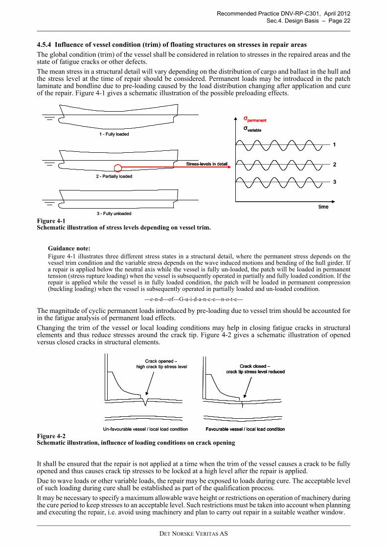
4.5.4 Influence of vessel condition (trim) of floating structures on stresses in repair areasThe global condition (trim) of the vessel shall be considered in relation to stresses in the repaired areas and thestate of fatigue cracks or other defects.The mean stress in a structural detail will vary depending on the distribution of cargo and ballast in the hull andthe stress level at the time of repair should be considered. Permanent loads may be introduced in the patchlaminate and bondline due to pre-loading caused by the load distribution changing after application and cureof the repair. Figure 4-1 gives a schematic illustration of the possible preloading effects.
Figure 4-1Schematic illustration of stress levels depending on vessel trim.
Guidance note:Figure 4-1 illustrates three different stress states in a structural detail, where the permanent stress depends on thevessel trim condition and the variable stress depends on the wave induced motions and bending of the hull girder. Ifa repair is applied below the neutral axis while the vessel is fully un-loaded, the patch will be loaded in permanenttension (stress rupture loading) when the vessel is subsequently operated in partially and fully loaded condition. If therepair is applied while the vessel is in fully loaded condition, the patch will be loaded in permanent compression(buckling loading) when the vessel is subsequently operated in partially loaded and un-loaded condition.
---e-n-d---of---G-u-i-d-a-n-c-e---n-o-t-e---
The magnitude of cyclic permanent loads introduced by pre-loading due to vessel trim should be accounted forin the fatigue analysis of permanent load effects. Changing the trim of the vessel or local loading conditions may help in closing fatigue cracks in structuralelements and thus reduce stresses around the crack tip. Figure 4-2 gives a schematic illustration of openedversus closed cracks in structural elements.
Figure 4-2Schematic illustration, influence of loading conditions on crack opening
It shall be ensured that the repair is not applied at a time when the trim of the vessel causes a crack to be fullyopened and thus causes crack tip stresses to be locked at a high level after the repair is applied.Due to wave loads or other variable loads, the repair may be exposed to loads during cure. The acceptable levelof such loading during cure shall be established as part of the qualification process.It may be necessary to specify a maximum allowable wave height or restrictions on operation of machinery duringthe cure period to keep stresses to an acceptable level. Such restrictions must be taken into account when planningand executing the repair, i.e. avoid using machinery and plan to carry out repair in a suitable weather window.
1 - Fully loaded
2 - Partially loaded
3 - Fully unloaded
Stress-levels in detail
σpermanent
σvariable
time
1
2
3
1 - Fully loaded
2 - Partially loaded
3 - Fully unloaded
Stress-levels in detailStress-levels in detail
σpermanent
σvariable
time
1
2
3
σpermanent
σvariable
time
1
2
3
Favourable vessel / local load condition
Crack closed –crack tip stress level reduced
Un-favourable vessel / local load condition
Crack opened –high crack tip stress level
Favourable vessel / local load condition
Crack closed –crack tip stress level reduced
Favourable vessel / local load condition
Crack closed –crack tip stress level reduced
Un-favourable vessel / local load condition
Crack opened –high crack tip stress level
DET NORSKE VERITAS AS

Recommended Practice DNV-RP-C301, April 2012Sec.5. Failure Mechanisms and Design Criteria – Page 23
5. Failure Mechanisms and Design Criteria
5.1 General
5.1.1 Objective and scopeThis section provides the design criteria for bonded repairs. A bonded repair consists typically of a patch(composite laminate or steel plate) applied to a metal substrate with an adhesive bondline, as shown in Figure1-1. The design criteria cover all three components and their interfaces. Detailed guidance on design and safetyphilosophy for composite components is given in DNV-OS-C501 Section 2.
5.1.2 ApproachThe reliability of the repair is assessed using limit state equations that represent the actions (loads) that affectthe repair and include an appropriate capacity model that predicts the repair’s capacity to resist these actions.The capacity may be affected by environmental factors. Design loads and load effects shall be taken according to 5.1.3.Other environmental effects shall be taken according to 5.1.4.The relevant failure mechanisms are given in Sub-Section 5.2. General design criteria are given in Paragraph 5.3.1. Specific requirements to Class 0, I, and II repairs are given in paragraphs 5.3.2, 5.3.3 and 5.3.4respectively.The partial safety factors to be used are given in Sub-Section 5.4.The characteristic material strength as described in DNV-OS-501 Section 4 shall be used for all calculationsfor composite laminates and adhesives. Both characteristic short term properties and characteristic long termproperties up to the design life shall be considered. How to obtain long term properties is described in DNV-OS-501 Section 4.
5.1.3 Loads and load effectsDesign loads and load effects shall be established according to established engineering principles. Specificmethods applicable to wave-induced load effects in bonded repairs are given in Section 6.2.Design load effects are obtained by multiplying the characteristic load effect by their corresponding load effectfactor. The design load effect is used in the design checks. Several combinations may have to be checked when loadeffects from several load categories enter one design check. The load effect factors shown in Table 5-3 shall beused.
5.1.4 Environmental effectsFor bonded repairs exposed to weather, the extreme design temperatures should be determined from the lowest,respectively highest daily mean temperature for the geographical area in question.Wind-chill and solar radiation effects should be considered for repairs exposed to weather, or where otherwiserelevant.Bonded repairs below the lowest waterline or in way of permanently heated compartments need not bedesigned for lower temperatures than 0°C. The suggested lowest design temperatures to be considered for evaluation of fracture toughness of substratesare the following:
Guidance note:Internal structures in non-heated compartments above LBW may be exposed to temperatures significantly below 0 °Cdue to cooling of adjacent structures directly exposed to weather.Structures below LBW are permanently submerged in seawater and are assumed not to experience temperaturesbelow 0 °C. Special structures for extreme arctic operation may pose more severe requirements for low temperatureperformance of structures below LBW.
---e-n-d---of---G-u-i-d-a-n-c-e---n-o-t-e---
For repairs designed to operate below the glass transition temperature, Tg of the matrix material and the adhesive,the maximum operating temperature should normally not exceed Ta = Tg - 20°C for any of the materials.
Table 5-1 Lowest design temperaturesStructure Normal operation Artic areasInternal structures 0°C Indirectly exposed structures above LBW: -20°C
Structures in way of heated compartments: 0°CStructures below lowest ballast water line (LBW)
0°C 0°C
Structures exposed to weather -20°C Lowest daily mean at geographical location
DET NORSKE VERITAS AS

Recommended Practice DNV-RP-C301, April 2012Sec.5. Failure Mechanisms and Design Criteria – Page 24
Characterisation tests may be done at one representative temperature if the service temperature range is lessthan 40°C, Ta is outside that range and no phase change occurs for any of the material in that temperature range.The representative test temperature would normally be the specified highest operating temperature. Otherwise,the test temperatures should be specially considered to ensure that representative strength data are used in thecapacity checks.
The effects of exposure to water shall be considered in the material selection for the patch, adhesive and primersif any. Generally, fresh water has a more severe degradation effect than salt water on most composites.Stagnant, rotten water or water with bacteria have unknown degradation effect on composites. If a repair isinstalled in a ballast tank or other confined space which is not regularly flushed / ventilated it may be necessaryto consider material degradation due to bacteriological activity.
5.2 Failure modes and failure mechanismsThe relevant failure modes and the associated failure mechanisms for Class I and II repairs are given in Table5-2. The relevance for crack and hole patching (CH) and other bonded repairs (O) is indicated as well aswhether the failure mechanism will be considered for Class I and II repairs (I,II) or only for Class II repairs (II)or whether the mechanism is non-critical and need not be considered (X) or not applicable (N/A).
5.3 Design criteria
5.3.1 General
If the repair can be subjected to surface actions that may degrade the performance of the repair such as e.g. UVlight, abrasion, wear and tear and/or local impacts, the surfaces shall be protected by a suitable coating or otherprotection system. If the original damage (e.g. substrate crack) may be prone to further development after therepair, the repair must be so designed as to allow for inspection of the damage.
Table 5-2 Failure modes and failure mechanisms of bonded repairsFailure mode Associated failure mechanisms CH* O**Patch debonding
Initial bondline cracking – When a crack is repaired, an initial crack through the thickness of the bondline will normally develop very quickly just above the crack. This initial crack is arrested when it reaches the fibre-reinforced patch and is thus harmless.
X N/A
Bondline fatigue debond propagation – Upon being exposed to repeated load cycles …… Where the repair keeps the crack together, a debond crack may initiate and propagate in the bondline thus partially separating the patch from the substrate. II N/A
… A debond crack may initiate and propagate from the free edges of the repair thus partially separating the patch from the substrate II II
Bondline fracture – If loading transmitted by the patch exceeds what can be transmitted by the bondline, the bondline will fracture and the repair fail. I,II I,II
Blister resistance – If a fluid pressure can build up in a crack or hole in the substrate thus pushing the patch off from the substrate and this pressure exceeds what can be resisted by the bondline, the bondline will fracture and the repair fail.
I,II N/A
Creep rupture – If the repair is exposed to a permanent load, the persistent effect of this load may be excessive creep and subsequent creep rupture that partly or fully separates the patch from the substrate.
II II
Change of material properties due to temperature changes may reduce the capacity of the bondline and lead to premature failure. I,II I,II
Diffusion and swelling induced stresses and plasticisation due to diffused compounds leading to premature failure of the bondline.† -† -†
Corrosion of substrate behind repair or undercutting corrosion. I,II I,IIPatch failure Patch matrix cracking – If the strain (or stress) in the patch exceeds a certain critical
level, matrix cracks will start to develop in the patch. I,II I,II
Patch fracture – If the loading transmitted by the patch exceeds the capacity of the patch, it will fracture and the repair fails. I,II I,II
Substrate failure
The load reduction produced by the repair is insufficient to prevent unacceptable growth of damage in the substrate. I,II I,II
Thickness reduction due to corrosion I, II I, IILoss of repair efficiency
Bondline fatigue debond propagation – (Described above) As the debond propagates, the repair becomes more flexible and less efficient in arresting the crack propagation in the substrate.
II N/A
* Crack or hole patching** Other bonded repair† It is currently beyond the state of the art to assess these mechanisms in an affordable way
DET NORSKE VERITAS AS

Recommended Practice DNV-RP-C301, April 2012Sec.5. Failure Mechanisms and Design Criteria – Page 25
Guidance note:E.g. if the damage is a fatigue crack, the repair may be designed such as to render the crack tip visible and any furthercrack development detectable by visual inspection.
---e-n-d---of---G-u-i-d-a-n-c-e---n-o-t-e---
The build-up of static electricity in the composite bonded repairs shall be avoided in explosions hazard areas.Specified conductivity requirements shall be obtained with the repair solution. If no specific requirements aregiven, the recommendations from ISO 14692-2 Section 6.6 should be applied to composite patches.
The materials used should be suitable for use in the intended service environment. Diffusion of volatilecompounds into or through the patch or adhesive material may have a degrading effect on the patch materialor cause corrosion, embrittlement or other degradation of the substrate. Where possible, materials andarrangement of substructures should be chosen such as to promote ductile or plastic type failures, rather thanbrittle type failures, as defined in DNV-OS-C501, Section 2 C400.
Guidance note:The ductile failure type is associated with failures in which the structure retains a certain amount of reserve capacityafter initial failure.The plastic failure is associated with failures in which the structure fails progressively without reserve capacity afterinitial failure.Brittle failure is associated with failures where the structure loses all structural capacity at initial failure.
---e-n-d---of---G-u-i-d-a-n-c-e---n-o-t-e---
Normally, the COV of the resistance of the repair bondline should be less than 15%. If this is not achieved, itis recommended to improve the patch manufacturing and installation process such as to reduce the COV. Inspecial cases a COV above 15% may be acceptable, but in such cases increased material factors must be usedfor the bondline capacity check instead of those given herein.
Normally, the COV of the resistance of repair patch laminates should be less than 10%. If this is not achieved,it is recommended to improve the patch manufacturing process such as to reduce the COV. In special cases aCOV above 10% may be acceptable, but in such cases increased material factors must be used for the patchlaminate capacity check instead of those given herein.
5.3.2 Class 0 repairs
Class 0 repairs may be accepted without explicit assessment of their reliability. However, some designguidelines and rules of thumb are given in what follows instead of acceptance criteria.
The repair should normally be balanced and the patch edges tapered.
The overlap length should normally not be less than 50 times the patch thickness.
Normally an adhesive should be used with a critical plastic shear stress not exceeding a conservative estimateof the through thickness shear strength of the patch material.
5.3.3 Class I repairs
For Class I repairs, a simplified capacity check is allowed that does not include long term properties andtherefore eliminates the need for fatigue and stress rupture testing. A larger safety factor is used in the staticstrength assessment to reduce the proneness to fatigue debonding in lieu of a detailed long term analysis.
The static bondline capacity shall be checked according to Section 6.3.2. Patch fracture is assessed at the endof the design life according to Section 6.3.4. The efficiency of the repair in reducing the stresses in the originalstructure is estimated according to Section 6.3.5 for nominal/initial bondline or with an assumed debond size.
5.3.4 Class II repairs
For Class II repairs a more rigorous approach than that for Class I repairs is required. The static capacity isassessed with the same methods as for Class I repairs, except that a realistic state of damage is assumed and areduced safety factor is allowed. The long term effects of cyclic and permanent loads are specifically accountedfor.
The bondline debond crack development during the design life of the repair is estimated according to Section 6.3.1. Bondline fracture is assessed for the remaining bondline at the end of the design life according to Section 6.3.2. Creep rupture is assessed for the remaining bondline at the end of the design life according to Section 6.3.3. Patch fracture is assessed at the end of the design life according to Section 6.3.4. The efficiency of therepair in reducing the stresses in the original structure is estimated for the remaining bondline at the end of thedesign life according to Section 6.3.5.
5.3.5 Class III repairs (informative)
For Class III repairs, rigorous assessment of degradation due to time-dependent processes is required such thatthe repair reliability can be documented with the confidence required for critical repairs. This can in principlebe done by reference to successful service experience, but that is currently not sufficiently documented.
DET NORSKE VERITAS AS
Recommended Practice DNV-RP-C301, April 2012Sec.5. Failure Mechanisms and Design Criteria – Page 26
Alternatively, the time dependent mechanisms could be modelled theoretically, but scientifically provenmodels and affordable tests to generate material properties are lacking. Therefore, Class III repairs are currentlynot covered by this RP.
Time-dependent mechanisms of particular concern include:
— Diffusion of moisture and other volatile compounds.— Swelling due to diffused compounds and associated swelling stresses.— Plasticisation due to diffused compounds.— Physical or chemical degradation of the constituent materials (resin, fibres, adhesives) due to the presence
of diffused compounds.— Physical or chemical degradation of the interfaces due to the presence of diffused compounds.— Gradual degradation due to local impact and abrasive loads.
Other safety factors than those specified herein would apply as the safety class of the repair may be Normal orHigh.
5.4 Safety factors
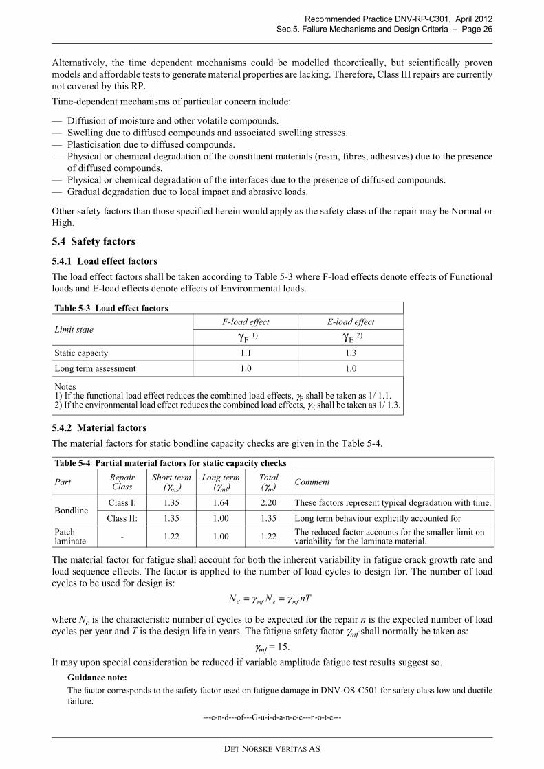
5.4.1 Load effect factors
The load effect factors shall be taken according to Table 5-3 where F-load effects denote effects of Functionalloads and E-load effects denote effects of Environmental loads.
5.4.2 Material factors
The material factors for static bondline capacity checks are given in the Table 5-4.
The material factor for fatigue shall account for both the inherent variability in fatigue crack growth rate andload sequence effects. The factor is applied to the number of load cycles to design for. The number of loadcycles to be used for design is:
where Nc is the characteristic number of cycles to be expected for the repair n is the expected number of loadcycles per year and T is the design life in years. The fatigue safety factor γmf shall normally be taken as:
γmf = 15.
It may upon special consideration be reduced if variable amplitude fatigue test results suggest so.
Guidance note:
The factor corresponds to the safety factor used on fatigue damage in DNV-OS-C501 for safety class low and ductilefailure.
---e-n-d---of---G-u-i-d-a-n-c-e---n-o-t-e---
Table 5-3 Load effect factors
Limit stateF-load effect E-load effect
1) 2)
Static capacity 1.1 1.3
Long term assessment 1.0 1.0
Notes1) If the functional load effect reduces the combined load effects, γF shall be taken as 1/ 1.1.2) If the environmental load effect reduces the combined load effects, γE shall be taken as 1/ 1.3.
Table 5-4 Partial material factors for static capacity checks
Part Repair Class
Short term (γms)
Long term (γml)
Total (γm) Comment
BondlineClass I: 1.35 1.64 2.20 These factors represent typical degradation with time.
Class II: 1.35 1.00 1.35 Long term behaviour explicitly accounted for
Patch laminate - 1.22 1.00 1.22 The reduced factor accounts for the smaller limit on
variability for the laminate material.
Fγ Eγ
nTNN mfcmfd γγ ==
DET NORSKE VERITAS AS
Recommended Practice DNV-RP-C301, April 2012Sec.6. Analysis Methodology – Page 27
6. Analysis Methodology
6.1 General
6.1.1 On modelling of fracture and debonding of bonded repairs (informative)
Guidance note:
In a bonded repair, the patch is normally designed with a strength in excess of the demands such that failure of thepatch itself is avoided. This can be achieved by well established methods. If such a bonded repair is subjected to aload that exceeds its resistance, a brittle debond fracture occurs. Many attempts at predicting such fractures by simplestress or strain criteria have been made, some reporting convincing agreement with selected experimental data. In adedicated study on bonded repair, a test programme involving a representative range of patch materials, bondlinethicknesses, and overlap lengths has been performed. It showed that a linear elastic stress approach underrated thebondline capacity by a factor ranging from 2 to 6 for different choices of patch materials and geometry. It is likely butnot proven that such linear assessment always underrates the capacity. The same study showed that, with the sameadhesive, the (inelastic) strain at fracture in one case was four times larger than in another case thus showing that thestrain at fracture is not a suitable measure of failure. This is contrary to popular belief, but consistent with the universalobservation that such debonds occur by brittle fracture.
On this basis, it seems appropriate to address the failure mode as a brittle fracture and employ fracture mechanicsprinciples. This is the approach used in what follows. One may argue that, based on careful consideration, a linearelastic stress criterion can be used as a conservative capacity check.
It has proven difficult to develop reliable fracture mechanics criteria where the fracture resistance parameters areestablished from idealised material tests and then used in a general model to predict failure of realistic repairconfigurations. Therefore, a pragmatic approach is used where the apparent fracture resistance is determined fromtests that correspond to the real repair configuration as closely as practically possible. The resulting apparent fractureresistance is used to predict the capacity of the real repair.
---e-n-d---of---G-u-i-d-a-n-c-e---n-o-t-e---
6.1.2 Application
Section 6.2 provides methods to establish the loads and load effects occurring at the bonded repair.
These loads and load affects can be combined with the models of repair failure mechanisms in Section 6.3 toassess the reliability of a specific repair design.
6.2 Loads and load effects
6.2.1 General
In case information about stresses is not available they can be back-calculated by using the following approach.
As the basis for designing bonded repairs, wave induced load effects may be assumed to follow a two-parameter Weibull distribution:
where S denotes the load effect, q is the Weibull scale parameter and h is the Weibull shape parameter.
— The shape parameter h depends on ship size and the location of the repair and should be determinedaccording to §4.3 of DNV Class Note 30.7 (2010).
— For wave-induced load effects S, the number of load cycles can be taken as 3 107 per year.
The representation of other loads (e.g. from machinery) should be in accordance with established engineeringpractice and relevant codes and standards.
6.2.2 Wave load effects established from global analysis
The characteristic load effects at the location of the repair for a given global load case may be determined froma global load effect analysis of the vessel or unit ignoring partial load factors. Such analyses shall be performedin accordance with established engineering practice and applicable codes such as e.g. DNV-OS- C101 andC102.
The Weibull scale parameter q can be taken as:
where Sc is the characteristic value of the load effect as determined from the global analysis.
( )
−−=h
q
SSF exp1
h
cSq 1
22
=
DET NORSKE VERITAS AS

Recommended Practice DNV-RP-C301, April 2012Sec.6. Analysis Methodology – Page 28
6.2.3 Load effects estimated from damage assessment and local analysisInstead of a global load effect analysis of the vessel or unit, the load effects at the location of the damage maybe estimated from the observed damage extent (crack length).The solution for the crack growth behaviour assuming crack growth according to Paris’ law can be taken as:
where Y is a geometry factor, a is the crack length (as a function of load cycle) ΔSi denotes each individualstress range, and A and m are the factors of the Paris law. For a particular long term distribution of stress ranges and denoting the integral on the left hand side by ψ, thisequation may be approximated by:
where E[ΔSm] denotes the expectation of the random variable ΔSm and ψ is the integral on the left hand side ofthe equation above. A geometry factor Y representing the damaged structure is required to solve this equation.Geometry factors for many idealised cases as well as methods to estimate geometry factors for more generalcases can be found in standard texts on fracture mechanics.The Weibull scale parameter q should be taken as that for which the observed crack length corresponds withthat predicted by the above formula. The characteristic static load may be taken as that with a return period of 100 years according to the Weibulldistribution:
Guidance note:Note that this estimate is very sensitive to the assumed Weibull shape parameter.
---e-n-d---of---G-u-i-d-a-n-c-e---n-o-t-e---
6.2.4 Simple upper bound for load effects An upper bound for the static load effect at the position of the damage may be established from the scantlingsand material properties taking into consideration the damage type and extent. E.g. if there is no evidence ofplastic deformations, the characteristic stress may be taken conservatively as an estimate of the actual yieldstress of the material (normally above the specified minimum yield stress).An upper bound for the long term distribution of wave-induced load effects can be established by combiningthe upper bound static load effect with an unfavourable long term distribution according to 6.2.1 taking theWeibull shape and scale parameters according to 6.2.1 and 6.2.2.
6.2.5 Local thermal loadsIf the service temperature may differ from the curing temperature of the patch application, local thermalstresses develop in the bonded repair. Unless these stresses are insignificant, they should be accounted for inthe analyses.
6.2.6 Deformation LoadsThe influence of the patch on the global and local deflections of the hull structure shall be evaluated if the patchchanges the stiffness of the repaired area.As for the permanent loads, large imposed deformations may lead to failure due to stress-rupture or over-straining. Load reversal shall also be considered for deformation loads.Deformation loads shall be defined using the same procedures as given for direct loads. This implies that alldeformation components (directions) shall be considered and that deformation loads shall be divided intopermanent and variable deformations.
6.2.7 Boundary conditionsAs for the loads, boundary conditions are mainly dependent on the structure in question and its location in thehull. Generally, it makes sense to consider three families of structures:
— Plates and plate fields— Beam-like structures— Brackets, lugs etc.
Plates and plate fields will normally be supported on 2, 3 or 4 sides. The boundary conditions on the supportedsides can be considered to be a combination of rotational degree of freedom, in-plane translational degree offreedom and out-of-plane translational degree of freedom.
( ) ( ) ( )=
Δ=N
i
mi
a
amm
SAaaY
daN
10 π
( ) [ ]mN SENAa Δ=ψ
qS hc
1
22=
DET NORSKE VERITAS AS
Recommended Practice DNV-RP-C301, April 2012Sec.6. Analysis Methodology – Page 29
Boundary conditions affect both the magnitude and location of the maximum curvatures in a plate, which againaffect the maximum imposed strains in a patch laminate applied on the plate.
Guidance note:A bonded repair is designed to carry the maximum strains imposed by lateral loading of a plate assuming high degreeof rotational freedom at the boundaries of the plate. This implies that the plate is assumed to carry the lateral loadthrough membrane action and that the maximum curvature is at the centre of the plate.If the rotational fixity at the edges is larger than assumed, the maximum curvature is located near the edges of the plateand the patch will fail through delamination or over-straining in this area. Thus realistic boundary conditions must beassumed.
---e-n-d---of---G-u-i-d-a-n-c-e---n-o-t-e---
Beam-like structures covers longitudinal and transverse stiffeners, free-spanning beams and also columns ifrelevant. Normally, only parts of continuous stiffeners or beams are considered, and the boundary conditionsshall reflect this in terms of degree of fixation at the ends of the considered beam segment.
For stiffeners welded to a plate field, part of the plate contributes as a flange on the beam. Shear lag effectsshall be considered when establishing the effective width of this apparent flange.
Brackets, lugs, local buckling stiffeners etc. normally have at least one free edge. The edges welded to theadjacent structures can normally be considered to be fully fixed.
6.3 Models of bonded repair failure mechanisms
6.3.1 Fatigue debonding growth
Fatigue debond crack growth can be considered governed by the following equation (modified Paris’ law):
where C and μ are material properties to be determined by experiment according to Sub-Sections 4 of AppendixG, Appendix H, Appendix I and Appendix J. C and μ generally depend on the mode mixity of the loading.
In general, ΔJ depends on crack length. This dependence is governed by the geometry and stiffness propertiesof the bonded repair.
The dependence of ΔJ(a) on a may be established by FEA.
The performance of the FE model should be demonstrated on a simple 2D example e.g. the test case used toderive the material properties.
By using the definition:
the debond advance for a given number of load cycles n of constant amplitude may be estimated by solving:
Ignoring sequence effects, the debond advance for a number Nc of variable amplitude loads may be estimatedby first setting n=1 in the equation above to obtain the advance for one cycle and then add the contributionsfrom all the expected load cycles during the lifetime of the repair considering a representative long termdistribution of the load effects. This would in general have to be done numerically.
The number of load cycles used for design shall be taken as:
where n is the expected number of load cycles per year and T is the design life in years. The material factor γmfis given in Section 5.
6.3.2 Static bondline capacity
When the loading reaches a critical level, the energy released by advancing the crack equals the bondlinefracture resistance. The selected approach to static bondline capacity assessment is to express the energybalance of the bonded repair as a function of crack length and differentiate with respect to crack length. Thisexpression involves negative terms corresponding to released energy and positive terms corresponding energyconsumed. During fracture, one term, Ri w a, denotes the energy consumed by the fracture. Ri is defined thebondline fracture resistance. At lower loads, the fracture resistance Ri in the expression may be substituted bythe strain energy release rate (or fracture load) denoted J. For a given repair subjected to a specified loading,this expression may be solved for J to produce an estimate of J at that load.
( )μJCdN
da Δ=
( ) ( )( ) Δ=
a
a aJ
daaf
0
μ
( ) Cnaf =
nTNN mfcmfd γγ ==
DET NORSKE VERITAS AS
Recommended Practice DNV-RP-C301, April 2012Sec.6. Analysis Methodology – Page 30
Fracture can be taken to occur when the fracture load J exceeds the fracture resistance Ri. Thus the acceptancecriterion becomes:
where Ri is the fracture resistance that corresponds to the failure mode investigated and should be establishedaccording to Sub-Sections 3 of Appendix G, Appendix H, Appendix I and Appendix J. The material factor γmis given in Section 5.
The static bondline capacity shall be checked for three different cases as relevant:
— Edge shear debonding – A debond that initiates at one of the free edges of the patch and propagatesunderneath the patch.
— Central shear debonding – A debond that starts from the substrate crack or other defect being repaired andpropagates from the center of the patch towards the edges.
— Blister debonding – A debond that is propagated by the action of a fluid pressure underneath the patch.
The strain energy release rate (fracture loading) can be estimated from
where the apostrophe indicates differentiation with respect to crack length a, w is the width of the patch andthe individual terms, each functions of a, are:
is the local elastic strain energy in the patch and the substrate
is the elastic strain energy in the repaired structural element
is the elastic strain energy in the adhesive
is the work by plastic deformations in the adhesive
is the work by plastic deformations in the repaired structural element
is the work done by the external forces
6.3.3 Bondline stress rupture
Stress rupture analyses shall be performed in accordance with DNV-OS-C501.
6.3.4 Patch fracture
For patches primarily loaded in one direction:
The stress in that direction shall not exceed
Patch fatigue fracture should be assessed according to DNV-OS-C501.
Otherwise, failure of the patch laminate shall be assessed according to the multiaxial failure criteria given inDNV-OS-C501.
6.3.5 Initial and long term repair efficiency
The repair is considered efficient if it is capable of reinstating the structural integrity as stated in the designbasis.
For crack-bonded repairs, this normally implies that the repair must reduce the stresses in the damaged elementto a level where the crack propagation is stopped, is reduced to a rate that is deemed acceptable considering theintended lifetime of the repair or that the crack can be shown to be arrested at some later time where the cracksize is still deemed acceptable.
For repairs of corroded elements, this implies full or partial restoration of capacity and/or stiffness.
The initial repair efficiency can be documented by appropriate modelling or testing of the repaired element inaccordance with established engineering practice and applicable codes and standards. If progressivedegradation of the repair (e.g. fatigue debonding) could affect the repair efficiency, the residual repairefficiency at the end of the design life of the repair may need to be documented.
JR
m
i >γ
′+′+′+′+′+′= emadhadhmlw WWWUUUJ 1
lU
mU
adhU
adhW
mW
eW
m
c
γσσ ≤
DET NORSKE VERITAS AS

Recommended Practice DNV-RP-C301, April 2012Sec.7. Materials – Page 31
7. Materials
7.1 General
7.1.1 General
This section gives guidance on how to obtain and evaluate material properties of substrate, adhesive and patchlaminate. The DNV Rules for Ships and the DNV-OS-C101 and DNV-OS-C102 contain more information onmetallic materials. The DNV-OS-C501 contains more information on composite materials and adhesives.
7.2 Substrate
7.2.1 General notes on substrate
General information on steel material grades and material protection for steel structures in ships can be foundin the DNV Rules for Classification of Ships. Additional information on selection and designation of materialsfor offshore ships is found in the DNV standard for design of offshore steel structures, DNV-OS-C101 Section4, and in the DNV standard for structural design of offshore ships, DNV-OS-C102 Section 2.
The information on substrate materials and material properties needed for the design of a bonded repair isdefined below in Subsection 7.2.2. For most repair designs the information outlined below is sufficient,however, for complicated or highly specialised designs, some additional information may be necessary. Thisshould be evaluated on a case-by-case basis.
7.2.2 Substrate material grades and minimum strength properties
The yield stress of the steel shall be taken according to the applicable code. The strength class, and thus theyield strength of the damaged structure must be known such that the correct value of the allowable stresses canbe determined. The Young’s modulus of the steel substrate should normally be taken as 210 GPa.
7.2.3 Fatigue and fracture mechanical properties
If specific values for the fracture mechanics parameters of the substrate steel are not available, the followingvalues may normally be used:
m = 3, A=5.21 · 10-13
where the units are da/dN in mm/cycle and ΔK in N/mm3/2.
7.3 Adhesives
7.3.1 General notes on adhesives
The adhesive material may be either a dedicated adhesive or it may simply be the matrix material serving alsoto form the bond against the substrate.
Bondline strength (per unit area) is dependent on a number of factors, most notably:
— surface condition and preparation of the substrate— adhesive strength and fracture toughness— void content in bondline— load directions.
These factors are controlled through design solutions and production process control.
All properties relevant for the analysis should be confirmed by experimental values from specimens withrepresentative bondline and adherend properties.
Characteristic material values shall be used for all properties. How to establish characteristic materialproperties is described in DNV-OS-C501.
7.3.2 Shear strength and fracture toughness
The shear strength and fracture toughness of the bondline shall be measured as described in Section 8.
7.3.3 Long term properties
The most critical long term properties are the fatigue behaviour of the bondline and long term degradation ofthe adhesive properties. The fatigue behaviour shall be characterised for Class II repairs as described in Section8.
Long term degradation of material properties due to exposure of the repair to the intended operatingenvironment is not explicitly considered for Class I and II repairs. However, only material combinations withgood durability in the intended operating environment shall be used. It is recommended that the screening testsprovided in Section Appendix F are used to identify such material combinations. Relevant long term propertiesmay be measured as described in DNV-OS-C501.
DET NORSKE VERITAS AS
Recommended Practice DNV-RP-C301, April 2012Sec.7. Materials – Page 32
7.4 Composite Materials
7.4.1 General notes on composite materialsThis section provides requirements for composite materials for use in bonded repairs. For the resins, the mainfocus is on thermosetting resins as these are either identical to, or readily compatible with the adhesives usedto form the bond between the substrate and the patch laminate.The exact combination of materials depends on the requirements to stiffness and strength of the finished repair,but also on the intended service environment, chosen or available production methods and the generalconditions under which the repair should be performed.
7.4.2 Relevant material propertiesMaterial properties and typical data for composite laminates are described in DNV-OS-C501. The materialproperties of the bonded repair must be tested according to the requirements of DNV-OS-C501. Typicalmaterial data provided in DNV-OS-C501 can be used when applicable to reduce the amount of testing for ClassI and II repairs. Characteristic material values shall be used for all properties, as described in DNV-OS-C501.Through thickness properties are very important for composite patch repair laminates. These properties areoften difficult to obtain, since they tend to be less relevant for other composite structures. DNV-OS-C501 givessome typical data and recommended test methods.
7.4.3 Fibre materialsFor most bonded repairs designed to perform as a structural part of the hull structure, the requirements forstrength and stiffness will necessitate the use of carbon fibres or equivalent.Due to concerns about galvanic corrosion however, any patch design using fibres that are conductive (e.g.carbon fibres) should be separated from the substrate. For prefabricated patches, this can be achieved by acontrolled bondline thickness. For patches laminated directly onto the substrate, the use of one or more layersof glass fibres as insulating layers is necessary to prevent corrosion of the substrate.
7.4.4 ResinsThe resin, or matrix material, may be either thermoplastic or thermosetting.Thermoplastic matrix materials may offer better resistance to some environmental exposure, but may alsoprove more problematic to bond to the steel substrate. Some thermoplastics need specialised surfacepreparation in order to obtain proper adhesion.Thermosetting matrix materials usually offer better bonding properties, as they are chemically compatible oridentical to the adhesive material itself. Thermosetting materials may be polyesters, vinylesters, epoxies ormore specialised resins, such as urethanes which may offer special processing or cure options, as e.g. the abilityto cure when exposed to water.
DET NORSKE VERITAS AS

Recommended Practice DNV-RP-C301, April 2012Sec.8. Qualification Testing – Page 33
8. Qualification Testing
8.1 General
8.1.1 Approach
This section specifies tests for qualification of bonded repairs:
— Screening tests recommended to aid material selection and repair process improvement.— Material characterisation tests used to obtain the input data required for theoretical models.— Component testing for direct experimental assessment of the repair.
The properties of patch laminates are established by dedicated tests.
Bondline properties are seen here as a combination of adhesive properties and the properties of the metal/adhesive interface or the composite patch/adhesive interface. The combined weakest link of these propertiesdetermines the performance of the bondline. Composite patches can be directly laminated to the metalsubstrate. In this case the first layer of resin takes the function of the bondline.
The adhesive and surface treatment combinations used for bonded repairs shall be tested. Data from othersources can be used as guidance but are not sufficient for the qualification of a bonded repair.
8.1.2 Test environment
The testing environment shall be representative for the service environment (e.g. temperature) as specified inthe design basis (see Section 4).
If the bonded repair is exposed to high loading rates, additional testing at such rates as specified in the designbasis may be required to establish the rate dependent material properties.
8.1.3 Specimen preparation
The manufacturing process should be representative of that specified for the real repair. Before the surfacetreatment and patch are applied the surface of the metal substrate should, as far as possible, be identical to thatof the element for which the repair is intended. The surface treatment shall be identical to the one used in theapplication in the field. The laminate shall be produced in the same way as in the real application. The rawmaterials shall be identical and the lay-up representative of the real repair. The adhesive shall be the same asin the real application and it shall be applied in the same way. The curing schedule of laminate and adhesiveshall be the same as in the real application.
8.2 Characterisation of bondline properties – General The aim of the bondline characterisation tests is to provide the inputs required for the theoretical models usedto predict the behaviour of the bonded repair. The amount of testing required depends on the models used.Generally, FE models require a rather detailed specification of material properties whereas some simplifiedmodels require only the most critical properties. In the following, the most critical parameters are covered.Should other material properties be needed as input to the models, they should be obtained in accordance withDNV-OS-C501.
The bondline characterisation tests shall be carried out for a range of patch materials covering the range ofpatch stiffnesses for which the adhesive system is intended to be used.
The shear modulus of the adhesive can be taken from data-sheets or established using standard test methods.
Guidance note:Generally, it is difficult to establish the shear modulus with great accuracy, but reliable capacity models are onlyweakly dependent on this parameter so that a rough estimate suffices. Usually, it is acceptable to perform an axial testof a cast specimen and determine G as E/(2(1+ν)). More representative values can be obtained with the TAST (seelast paragraph in Section Appendix F), but that requires rather sophisticated instrumentation.
---e-n-d---of---G-u-i-d-a-n-c-e---n-o-t-e---
The critical shear stress and fracture toughness of the adhesive bondline shall be determined according to Sub-Section 3 of Appendix G, Appendix H, Appendix I or Appendix J.
The fatigue debonding rate of the adhesive bondline shall be determined according to Sub-Section 4 of Appendix G, Appendix H, Appendix I or Appendix J as appropriate.
The stress rupture performance of the adhesive bondline shall be determined according to Sub-Section 5 of Appendix G, Appendix H, Appendix I or Appendix J as appropriate.
To characterise the effect of environmental degradation, identical tests to those above can be done onspecimens suitably preconditioned such as to represent the degradation that may be expected in the operationalenvironment specified in the design basis. Characteristic long-term properties shall be obtained from the testresults as described in DNV-OS-C501.
DET NORSKE VERITAS AS

Recommended Practice DNV-RP-C301, April 2012Sec.8. Qualification Testing – Page 34
8.3 Characterisation of laminates and metalsTesting requirements for laminates are the same as given in DNV-OS-C501. Through thickness properties canbe critical for composites and are often not readily available. Through thickness shear properties may needsome testing.
Data for the metal substrate can be obtained from DNV-OS-C101 and DNV-OS-C102.
8.4 Component testing
8.4.1 General
This sub-section provides guidelines and criteria for qualification of bonded repairs based on experimentalmodels of the entire repaired component.
The scope covers cases:
— which are not covered by the theoretical models elsewhere in this RP;— where the choice of materials, manufacturing procedures, geometry or the design is otherwise such that the
data commonly applied cannot be considered without further evidence to properly reflect the actualcircumstances;
— in which the theoretical models elsewhere in this RP would seem to lead to very conservative results and adirect experimental assessment of the limit states is envisaged to provide a more economical solution.
A detailed plan of the experimental programme shall be documented and reviewed before commencement ofthe programme. This plan shall be based on a rough quantitative preliminary analysis, or otherwise a qualitativeassessment, to identify the relevant functional requirements, potential failure mechanisms and relevant failuremodes including possible critical zones where these failure modes may materialise. On this basis, unambiguousdefinitions should be given of the limit states to be considered.
The tested repairs should be produced in the same size, by the same technology and by the same contractor asthose repairs to be qualified. The qualification of the patch configuration will be valid for the configurationtested. The validity may be extended to other geometries if the patch configuration can be scaled. Requirementsto scaling of large scale testing are given in DNV-OS-C501.
The test procedure should aim at recording the effects of phenomena relevant to the failure mechanisms andmodes (not only record the final values). The conditions during testing generally differ from those of the repairin service. These differences may be
a) size effects,
b) time effects due to the limited time available for testing compared to the intended service life of the repair,
c) boundary conditions not fully representative of the real conditions and
d) environmental effects that may affect the properties of the materials over time.
The evaluation of the recorded test data should be based on appropriate theoretical knowledge, experience intesting and sound engineering judgement considering the issues mentioned above.
8.4.2 Design qualification based on component testing only
A sufficiently large number of tests shall be carried out in order to be able to define the characteristic strengthof the repair with a confidence level at least as large as required for the data used with the analytical approach.
The characteristic values should be derived from the test data according to DNV-OS-C501.
8.4.3 Design qualification based on a combination of an analytical and experimental models
In cases where theoretical models exist but their accuracy is questionable or they are believed to produceuneconomical results, the theoretical model predictions may be combined with experimental model predictionsto form the basis for design qualification. The purpose is to update the theoretically predicted repair capacitywith the results from a limited number of tests in a manner consistent with the reliability approach of this RP.
Simple theoretical models are sometimes based on simplifying conservative assumptions leading to modelprediction biased to the safe side. In general, the introduction of conservative simplifying assumptions hinderscombination of model predictions and component tests. However, if the simplifying assumptions provide anunbiased prediction of a measurable state in a suitable component test (e.g. attainment of a certain strain levelat a particular spot, onset of nonlinearity or initial cracking), then the prediction may be updated based on suchcomponent tests according to the procedure described in DNV-OS-C501.
8.4.4 Testing for capability to stop crack growth
The most severe load direction for crack growth in the metal shall be tested.
If multiple load directions are critical and confidence into the calculation methods cannot be achieved withtesting in one load direction, more testing may be required.
DET NORSKE VERITAS AS

Recommended Practice DNV-RP-C301, April 2012Sec.8. Qualification Testing – Page 35
One test to failure shall be performed to obtain the static strength and failure mechanism. The failure strengthshall be higher than the predicted mean strength minus one standard deviation. The experimentally observedfailure mechanism shall be the same as the one predicted in calculations. More details can be found in DNV-OS-C501.Two fatigue survival tests shall be performed. Testing shall be done up to at least 10000 cycles. The appliedload shall be high enough that failure would be expected at 10000 cycles plus the logarithm of one standarddeviation in predicted lifetime. The specimens shall survive the test. More details can be found in DNV-OS-C501.
DET NORSKE VERITAS AS
Recommended Practice DNV-RP-C301, April 2012Sec.9. Fabrication Procedures and Quality Assurance – Page 36
9. Fabrication Procedures and Quality Assurance
9.1 General
Designers of the bonded repairs and application personnel should be qualified through a recognizedcertification or documented practical experience.
This section gives guidance on applicable procedures for surface preparation, bonding and patch fabrication.Critical production issues are identified with the purpose of assisting the designer in specifying a successfulquality assurance scheme.
Step by step manufacturing procedures should be provided. Each step should be assessed and found to besimple and insensitive to foreseeable deviations from the specified procedure.
A QA/QC system should be in operation that covers each step and that requires each step to be signed off byqualified and responsible personnel according to the authorisation specified in the QA system.
As a means to control the quality of surface treatment and bonding, pull-tabs may be installed at the same timeas the repair using the same materials an procedures. After cure, the pull-tabs can be pulled off from thesubstrate and the pull-off strength compared to the specified values.
9.2 Substrate – Surface preparation
The surface preparation shall be done to achieve a satisfactory bond to the substrate.
Prior to blasting operations, any grease, oil and other contaminations shall be removed according to SSPC-SP-1.
Removal of the remains of coatings, scale and rust shall be done by blast cleaning or other suitable technique.Dry blast cleaning, hydrojetting or other surface cleaning techniques may be used if the cleaning proceduresprovide the required bond strength. Cleanliness of the surface should be to SA 2½ according to ISO 8501 –1for blast cleaning or equivalent for the use of other surface cleaning procedures. Dust, blast abrasives and otherloose particles shall be removed from the surface.
The surface shall be blast cleaned to provide an anchor pattern for the bonding. The bond strength shall bedemonstrated by testing to be in accordance with the requirements given in Section 8. The surface profile ofthe surface shall be in the range 75 to 115 μm according to ISO 8503. Moreover, the surface shall have a solublesalt concentration of no more than 80mg/m2.
Priming of the cleaned surface may be done to avoid the formation of rust blooms, reduce the sensitivity tocontamination of the surface and to enhance the bond strength between the steel substrate and the patch. Thebond strength of the primed surface shall be demonstrated by testing in accordance with the requirements givenin Section 8.
9.3 Patch fabrication
9.3.1 General
This section gives guidance on control of relevant process parameters and production methods involved in thepatch fabrication process.
This guideline considers mainly patches made from fibre reinforced plastics (FRP), where the matrix materialmay be either thermosetting or thermoplastic.
Section 7 gives specific guidance on materials and should be referenced for details on material properties,material testing and qualification.
The fabrication requirements given in DNV-OS-C501 Section 11 shall be considered for bonded repairs.
Two main concepts of patch fabrication methods exist:
— Fabrication of pre-formed patch elements, i.e. plates, strips, staves to be bonded onto the substrate.— On-site fabrication of patch, i.e. direct lamination of patch onto substrate.
9.3.2 Fabrication of pre-formed patch elements
Pre-formed patch elements are generally produced in a workshop, either on-shore or in a purpose-built on-board workshop, allowing good control of production parameters.
The patch elements are produced in, or onto, a mould, which is designed based on the substrate geometry. It isimportant that the pre-formed patch conforms well to the substrate geometry, such that the patch is not forcedout of its neutral shape when bonded onto the substrate.
Guidance note:Residual stresses introduced by forcing a patch to conform to the substrate geometry by bending of the patch willintroduce tensile stresses in parts of the bondline. This will lead to a reduced maximum bond strength compared to abondline free from initial tensile stresses.
DET NORSKE VERITAS AS
Recommended Practice DNV-RP-C301, April 2012Sec.9. Fabrication Procedures and Quality Assurance – Page 37
Pre-stressing the patch may be desirable to reduce strains or crack tip opening displacements. Pre-stressing introducesadditional shear stresses in the bondline, which, although not as critical as tensile stresses must also be consideredwhen evaluating the maximum strength and load carrying capacity of the repair.
---e-n-d---of---G-u-i-d-a-n-c-e---n-o-t-e---
A number of lay-up and fabrication methods are available, and the choice of fabrication methods is mainlygoverned by requirements to patch geometry and dimensional tolerances, requirements to production quality,available workshop facilities and tools, to some degree the available time and whether or not the design is fora one-off repair or a repetitively occurring repair design.
The main fabrication methods can be summarised as follows:
— Hand lay-up / wet lay-up onto mould, cure under vacuum bag or equivalent:
— This method requires the least preparations and the least amount of tools but a comparatively skilledoperator to achieve a good quality. The operator manually impregnates reinforcement layers and placesthese onto the mould. Complex shapes can be produced and the method is well suited for one-offproduction or small production series.
— The quality of the laminate directly depends on the operator skill and care during the impregnation andlay-up process.
— Pre-preg lay-up in / onto mould, cure in mould or under vacuum bag:
— Using pre-impregnated reinforcement layers in the lay-up process eliminates the need to handle resinsduring the fabrication process and ensures better control over the impregnation process and the fibre –resin ratio in the finished laminate and thus a more uniform laminate quality. Other features are similarto those of a wet lay-up laminate.
— Resin infusion techniques:
— Several variations of resin infusion techniques are available but the most common are probably RTM(Resin Transfer Moulding) in closed moulds and RIFT (Resin Infusion under Flexible Tools). Bothrequire experience with the process and are sensitive to control of resin amounts and resin flow toensure complete and uniform wet-out of fibres. When set up properly, both methods produces laminatesof excellent quality and finish. Relatively complex shapes can be produced, but resin flow patterns andde-moulding after cure must be considered.
— Extrusion or pultrusion:
— Extrusion or pultrusion techniques may be used to produce prismatic elements such as flat or curvedplates, bars, strips etc. in virtually any length. This production method lends itself to production of alarge number of identical elements, and very consistent quality and dimensional accuracy can beachieved. Both thermosetting and thermoplastic matrix materials can be used.
Alternatively, patches can be made up of metallic sheet materials such as steel or aluminium.
Handling and application procedures for the structural adhesive are given separately in Section 9.4.
9.3.3 Direct lamination
Direct lamination of patches onto substrate similarly requires control of key parameters to obtain both sufficientbondline strength and sufficient patch laminate strength.
The most important process parameters are:
— Surface preparation of substrate:
— The substrate must be cleaned and prepared to a specific roughness to ensure proper adhesion. Therequirements for surface preparation are given in Section 9.2.
— Handling and preparation of constituent materials
— Control of lay-up:
— The stacking sequence and orientation of individual reinforcement layers must be done according tospecifications by the designer to ensure correct performance of the patch.
— The tapering is produced by the variation in length of the reinforcement layers which must be placedaccurately to form the correct taper angles and –lengths.
— The resin may be applied beyond the reinforcement.
— Control of wet-out:
— When using wet lay-up processes, sufficient wet-out must be ensured for each applied reinforcement layer.
DET NORSKE VERITAS AS
Recommended Practice DNV-RP-C301, April 2012Sec.9. Fabrication Procedures and Quality Assurance – Page 38
— Control of cure temperature and cure time:
— The cure temperature and cure time for the laminates must be controlled to obtain sufficient bondlinestrength.
9.3.4 Handling and preparation of constituent materialsCorrect handling and preparation of constituent materials must be ensured in order to obtain the expectedquality and mechanical properties of the patch laminate. The following information represents minimumrequirements. More specific handling and fabrication instructions may be given by the material supplier andshall in such cases supplement or replace the advice given here.Handling and application procedures for the structural adhesive are given separately in Section 9.4.A two-component matrix resin shall always be mixed to the ratio specified by the supplier. Adjusting themixing ratio to obtain different cure times or temperature tolerances etc. is not allowed except wherespecifically approved by the resin supplier.When laminating with a certain resin, the lamination process shall be planned such that it can be completedwithin the available pot-life of the resin. Mixed resin which has exceeded the specified pot-life is not allowedin production and shall be discarded.Dry fibre materials such as fibre tape or reinforcement mats shall be stored and transported under controlledhumidity and temperature conditions. When used in the lamination process, the moisture content shall bewithin the allowable range specified by the material supplier and it shall be verified that relevant material testshave been carried out using samples produced from reinforcements with comparable moisture content.Dry fibre materials shall be protected from contamination during storage and transport. Examples ofunacceptable contamination include dust or debris containing abrasive particles (sand, metal particles etc.), saltwater or salt spray which may leave salt crystal deposits on fibres etc. Such contamination of the fibre materialswill lead to unacceptable inclusions of debris in the laminate, possibly causing delamination, internal wear orproviding crack inducers leading to loss of fatigue capacity.Reinforcement mats or tape made from pre-impregnated material (pre-preg) shall be protected fromcontamination in similar fashion to dry fibre materials. In addition, specified storage temperature andmaximum shelf-life must be observed to avoid premature onset of the cure process.Pre-preg materials which have been exposed to temperatures above the allowable storage temperature or storedbeyond the specified shelf life are not allowed in production and shall be discarded.When producing laminates from pre-pregs care must be taken to ensure that the lay-up process, including fittingof relevant curing fixtures, vacuum bags etc. can be completed within the available room-temperature workingtime for the material. A complete work instruction, including bill of materials, SHE-instructions, mixing ratios, lay-up sequence andlaminating procedures shall always be made available to the laminator performing the patch fabrication.
9.3.5 Lay-up of laminateFor patch laminates made from reinforcement layers with specific fibre orientations, the lay-up and stackingsequence is important and the laminator must ensure that the finished laminate has correct fibre orientationsaccording to specifications.A description of fibre-orientations and stacking sequence shall be made available to the laminator. Thedescription shall be supported by a drawing, clearly specifying orientation of layers relative to the substrategeometry.If a pre-formed patch is laminated in a workshop for later installation onboard a vessel or unit, the orientationof fibres shall be marked clearly on the outermost layers to ensure correct orientation of the patch wheninstalling on site.
9.3.6 Control of wet-outWhen producing laminates by wet lay-up techniques, the laminator must ensure that there are no areas or layerswith insufficient wet-out. Simultaneously, excessively resin rich areas must be avoided. The laminator mustreceive relevant training to possess appropriate competence in the lamination process.If using lay-up of pre-preg laminates, wet-out problems do not exist, but the laminator must inspect each layerfor damages such as torn fibres, insufficient impregnation, partially cured layers etc. before they are used in thelaminate stacking.
9.3.7 Control of cure parametersThe cure and / or post-cure time shall be at least as specified by the resin supplier. The specified cure and / orpost-cure temperature shall be maintained throughout the entire cure time.The patch shall preferably be left to cure and post-cure in an unloaded condition. If complete unloading of thesubstrate structure cannot be achieved, the loads must be kept within specified limits for which sufficient bondstrength has been demonstrated.
DET NORSKE VERITAS AS
Recommended Practice DNV-RP-C301, April 2012Sec.9. Fabrication Procedures and Quality Assurance – Page 39
Barcol hardness tests shall be performed on all cured polymeric materials. Values shall match the specifiedvalues and the values obtained in the qualification testing.The global condition (trim) of the vessel or unit shall be considered. If possible, the vessel or unit shall betrimmed such as to close fatigue cracks. See also Section 5.The wave bending induced stresses on the relevant detail shall be established. The allowable wave height shallbe specified based on the allowable stresses during cure, and the repair shall only be initiated if forecasts predictsea-states within the allowable with a reasonable degree of certainty.
9.4 Adhesive Bonding
9.4.1 GeneralThis section deals with control of the formation of the adhesive bond between the substrate and the patchlaminate – the “bondline”.This section mainly focuses on bonding of pre-formed patch elements using a structural adhesive but theconsiderations are equally applicable for controlling the properties of the bondline when laminating the patchdirectly onto the substrate, i.e. forming the bondline in the patch lamination process.
9.4.2 Overview of process parametersBonding of patches onto a substrate requires control of a number of key process parameters in order to obtainsufficient bond quality.The most important process parameters are:
— Surface preparation of substrate and patch:
— The surfaces to be bonded must be cleaned and prepared to the specified cleanliness and roughness toensure proper adhesion. The requirements for surface preparation are given in Section 9.2.
— Control of bondline thickness:
— The bondline thickness may influence the strength, particularly in peel, of the interface and must becontrolled to fall within the limits specified in the design report.
— Control of contact pressure:
— When fixing the patch onto the substrate during cure, the contact pressure between patch and substrateinfluences the bondline thickness and must be controlled. The contact pressure ensures proper wettingof the substrate surface by the adhesive and fixation of the patch while the adhesive cures.
— Control of alignment:
— The patch must be aligned carefully to ensure that the reinforcement is placed in the correct locationand with the correct alignment relative to the substrate.
— Control of cure temperature and cure time:
— The cure temperature and cure time for the adhesive must be controlled to obtain sufficient bondlinestrength. These parameters must be specified in the fabrication procedure.
9.4.3 Control of bondline thicknessThe thickness of the bondline shall be controlled to obtain the engineered properties. Too thick or too thin abondline will alter and possibly weaken the bond compared to a bondline of the specified thickness.Correct bondline thickness shall be maintained by fixtures or spacers until the adhesive has cured sufficientlyto prevent movement of the patch.If spacers are used for control of bondline thickness and remain embedded in the bondline after cure, their effectas local delamination or crack initiators shall be accounted for in the design of the bonded repair.The adhesive and patch shall be applied in a way that dry spots or air inclusions do not occur.For patches laminated directly onto a substrate, the bondline thickness requirement is usually not relevant.For patches laminated directly onto a substrate, proper wet-out of the first reinforcement or insulating layershall be verified. Dry spots or excessively resin rich areas are not allowed and shall be corrected by thelaminator before the subsequent reinforcement layers are applied.
9.4.4 Control of alignmentThe patch must be installed with correct orientation relative to the substrate geometry, i.e. the fibre orientationsmust be as specified relative to the substrate geometry and load directions.The installation procedure shall contain an acceptable tolerance on the alignment, typically specifying amaximum allowable misalignment in degrees.
DET NORSKE VERITAS AS

Recommended Practice DNV-RP-C301, April 2012Sec.9. Fabrication Procedures and Quality Assurance – Page 40
9.4.5 Control of cure parametersThe cure and / or post-cure time shall be as specified in the fabrication procedure. This information may beprovided by the adhesive supplier or is established during acceptance testing. The specified cure and / or post-cure temperature shall be maintained throughout the entire cure time.The contact pressure shall be controlled and shall be as specified in the fabrication procedure.
Guidance note:Excessive contact pressure may cause the adhesive to be squeezed out, eventually causing dry spots. Loss of contactpressure may lead to loss of alignment or incorrect bondline thickness.
---e-n-d---of---G-u-i-d-a-n-c-e---n-o-t-e---
The adhesive shall preferably be left to cure and post-cure in an unloaded condition. If complete unloading ofthe bondline cannot be achieved, the loads must be kept within specified limits for which sufficient bondstrength has been demonstrated.The global condition (trim) of the vessel or unit shall be considered. If possible, the vessel or unit shall betrimmed such as to close fatigue cracks. See also Section 3.The wave bending induced stresses on the relevant detail shall be established. The allowable wave height shallbe specified based on the allowable stresses during cure, and the repair shall only be initiated if forecasts predictsea-states within the allowable with a reasonable degree of certainty.
9.5 PersonnelThe entire repair process is a manual process. Hence the quality of the bonded repair is directly dependent onthe skill and experience of the personnel carrying out the repair. As part of the fabrication instructionsdocumentation must to be provided that the personnel carrying out the repair is qualified for the job.
Guidance note:There are some national qualification schemes for composite technicians or the EWF Adhesive Bonder / AdhesiveSpecialist / Adhesive Engineer scheme or documented practical experience.
---e-n-d---of---G-u-i-d-a-n-c-e---n-o-t-e---
DET NORSKE VERITAS AS
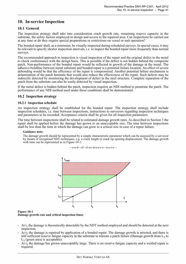
Recommended Practice DNV-RP-C301, April 2012Sec.10. In-service Inspection – Page 41
10. In-service Inspection
10.1 GeneralThe inspection strategy shall take into consideration crack growth rate, remaining reserve capacity in thesubstrate, the safety factors employed in design and access to the repaired area. Can inspections be carried outat any time or do they require special preparations or restrictions on vessel or unit operation?
The bonded repair shall, as a minimum, be visually inspected during scheduled surveys. In special cases, it maybe relevant to specify shorter inspection intervals, i.e. to inspect the bonded repair more frequently than normalsurveys.
The recommended approach to inspection is visual inspection of the repair and the original defect in the metalto check conformance with the design basis. This is possible if the defect is not hidden behind the compositepatch. Non-performance of the bonded repair would be reflected in growth of the damage in the metal. Theadhesive bondline between metal substrate and bonded repair is a potential failure location. An effect of severedebonding would be that the efficiency of the repair is compromised. Another potential failure mechanism isdelamination of the patch laminate that would also reduce the effectivness of the repair. Such defects may beindirectly detected by monitoring the development of defect in the steel structure. Complete separation of thepatch from the substrate can also be easily detected by visual inspection.
If the metal defect is hidden behind the patch, inspection requires an NDI method to penetrate the patch. Theperformance of any NDI method used under those conditions shall be demonstrated.
10.2 Inspection strategy
10.2.1 Inspection schedule
An inspection strategy shall be established for the bonded repair. The inspection strategy shall includeinspection schedules, i.e. time between inspections, instructions to surveyors regarding inspection techniquesand parameters to be recorded. Acceptance criteria shall be given for all inspection parameters.
The time between inspections shall be related to estimated damage growth rates. As described in Section 3 therepair shall be applied before the damage has grown to an unacceptable size. The time between inspectionsshall be less than the time in which the damage can grow to a critical size in case of a repair failure.
Guidance note:The damage growth should be represented by a simple characteristic parameter which can be assessed by a surveyorby means of recognised NDT-techniques, e.g. a crack length or crack tip opening displacement. The damage growthwith time can be represented as in Figure 10-1:
---e-n-d---of---G-u-i-d-a-n-c-e---n-o-t-e---
Figure 10-1Damage growth rate and critical inspection times
- At t1 the damage is theoretically detectable by the NDT method employed and should be detected at the nextinspection.
- At t2 the damage is repaired by application of a bonded repair. The damage growth is arrested, and there isstill sufficient reserve fatigue capacity in the substrate to tolerate a patch failure (Damage growth from L2 toL3 (green area) is acceptable).
- At t3 the damage has grown unacceptably large. There is no reserve fatigue capacity and a welded repair isrequired.
Ldam
t
t1 t2 t3
L1
L2
L3
Ldam
t
t1 t2 t3
L1
L2
L3
DET NORSKE VERITAS AS

Recommended Practice DNV-RP-C301, April 2012Sec.10. In-service Inspection – Page 42
Guidance note:The inspection strategy and the time between inspections shall be chosen such that the damage will not grow beyondthe critical size before the next inspection, even if the patch should fail on the first day after installation.
---e-n-d---of---G-u-i-d-a-n-c-e---n-o-t-e---
The damage growth rate and remaining time to reach a critical damage size shall be established for the substratein all repair cases and the results shall be available in the design documentation and inspection manual.
10.2.2 Critical crack length
For damaged structural details, the critical damage size shall be established. This may be done based onexperience from similar details under similar loading conditions, by direct calculations or a combination ofthese. FE-analyses may be used to determine stress distributions and stress concentrations.
The reserve capacity in the local structure with a critical damage shall be established. Adjacent structures mayprovide structural redundancy and lead to larger acceptable damages.
Guidance note:The acceptable crack length in e.g. a cracked bottom or side longitudinal may be relatively large since the damagedstiffener is part of a complex bottom structure and the remaining stiffeners ensure redundancy, provided they are notdamaged to any significant degree. The acceptable crack length in e.g. a cracked machinery foundation may berelatively small since failure of the foundation will lead to potentially dangerous situations and service interruptions.
---e-n-d---of---G-u-i-d-a-n-c-e---n-o-t-e---
10.3 Inspection of the metal substrate
10.3.1 Monitoring of damage development
Damage in the substrate shall be described by a limited number of characteristic parameters to facilitatemonitoring of damage development over time.
Relevant characteristic parameters for damage size and development depend on the damage type and locationin the structure. Examples are:
— Fatigue cracks are characterised by crack length or alternatively crack tip opening displacement.— Corrosion damage may be characterised by e.g. corroded area, corrosion depth, related to the total available
(load-carrying) area or thickness of the panel / detail. Guidance can be found in e.g. the IACS GuidanceManual for Tanker Structures, Appendix VIII Part 5.
10.3.2 Technology and methods for inspection of substrate
A number of non-destructive inspection methods and technologies exist for metals. Examples of NDI methodswhich may be applicable include:
— ultrasonic thickness gauging— thermography— x-ray.
If the metal defect is completely covered by the composite patch, the main challenge consists in achievingreliable detection of damage development through coatings and possibly through patch laminate and adhesivesif the bonded repair completely covers the damaged area. In this case the applied NDI technology shall bequalified by testing on simulated damages.
The NDI operator shall receive specific training and be certified as operator of the NDI equipment. Theoperator shall have representative samples of damages with coatings / bonded repairs available for calibrationof equipment.
10.4 Inspection of bondline
10.4.1 Monitoring of damage development
At present, no reliable methods for detection and monitoring of initial damage in the bondline have beenidentified.
Detecting and monitoring bondline damage under development may be difficult. In the unlikely event thatdamage occur, it is expected for simple 2D repairs that the damage develops progressively.
10.4.2 Technology and methods for inspection of bondline
At present, no reliable technology for inspection of the bondline has been identified.
New technology and / or inspection methods may be employed for monitoring of bondline integrity providedthey are demonstrated and qualified for the relevant application through testing.
DET NORSKE VERITAS AS

Recommended Practice DNV-RP-C301, April 2012Sec.10. In-service Inspection – Page 43
10.5 Inspection of patch laminateDelamination in the laminates is an important failure mechanism that reduces stress transfer from the metalsubstrate in to the laminate. NDI may be specified to detect such failure. NDI methods could be ultrasound,thermography, “coin tap method” and possibly x-ray.
DET NORSKE VERITAS AS

Recommended Practice DNV-RP-C301, April 2012App.A Survey Procedures – Page 44
APPENDIX A SURVEY PROCEDURES
A.1 General
This section describes inspections that may be carried out during scheduled surveys in order to identify damagecases for which bonded repairs may be suitable. APPENDIX C shows a checklist that can be used to record thefindings of the survey.
The inspection routines and actions described in this document are optional additions to the normal surveyprogramme and shall under no circumstances replace or otherwise take precedence over the survey programmespecified by the classification society or authorities.
The owner and operator of the vessel or unit shall explicitly specify to the surveyor that additional inspectionshall be carried out during a scheduled survey with the intention of identifying possible areas for bonded repair.
A.2 Location of the damage
The location of the damage in the hull shall be described and documented by drawings and photographs. Adescription of the damage shall at least contain the elements listed in Table A-1.
A.3 Assessment of damage type and damage extent
The damage type shall be recorded by the surveyor. Corrosion and fatigue damages are the main applicationsfor bonded repairs.
Typical areas include corrosion on horizontal surfaces due to accumulation of moisture and fatigue cracking atjoints, bracket toes, bulkhead openings etc.
The surveyor shall pay special attention to damage under development, even though a given damage isacceptable under the applicable survey scheme.
Guidance note:
Well advanced corrosion with significant breakdown of substrate or extensive fatigue cracking presents greatdifficulties in terms of achieving sufficient patch and bondline strength.
Advancing damages which are detected and repaired at an early stage may be arrested altogether and thus reduce oreliminate the need for future repairs in that area.
---e-n-d---of---G-u-i-d-a-n-c-e---n-o-t-e---
The function of the damaged component shall be recorded and the basic functional requirements considered.The basic functional requirements as identified by the surveyor shall be available when the feasibility of abonded repair of the component is evaluated.
Guidance note:
Basic functional requirements are those which are immediately obvious to the surveyor, such as e.g.
— A panel is corroded. It must resist water pressure from a full ballast tank, hydrostatic head approx. 5 m.
— A door frame in a bulkhead suffers from initial fatigue cracking. The fatigue cracking must be arrested, and thedoor frame must still allow the door to close. If the bulkhead and door form a waterproof collision bulkhead,watertight integrity must be restored.
— A support structure for a pump suffers fatigue cracking. The fatigue cracking must be arrested and the patch (andrepaired structure) must be able to resist fatigue loads due to vibrations. In addition the patch must possibly resistvarious chemicals if the pump suffers a leak.
---e-n-d---of---G-u-i-d-a-n-c-e---n-o-t-e---
Table A-1 Requirements to description of damageList entry CommentDescription and dimensions of structure to be repaired.
Give drawings of the structure that should be repaired. This should include immediate surrounding areas.
Location Give exact location of the damage in the ship. Support with indication of location in general arrangement drawings.
Extent of damage Describe dimensions and extent of damage or defects in the steel structure. Support with drawings and photographs. Define also operating requirements, e.g. pressure, temperature, type of fluid.
Photo documentation Provide photos of the damaged case showing all surfaces where patches may potentially be bonded, e.g. both sides of cracked plates.
DET NORSKE VERITAS AS

Recommended Practice DNV-RP-C301, April 2012App.B Criticality Assessment of the Damage – Page 45
APPENDIX B CRITICALITY ASSESSMENT OF THE DAMAGE
When the damage has been detected and documented, a criticality assessment shall be made. The repair of astructural element is non-critical if the element itself is non-critical. If the damaged element is critical but the extent of the damage is such that it does not compromise the integrityof the element and will not develop to such an extent within the next inspection interval, the repair is non-critical. The preferred time for application of a bonded repair is illustrated in Figure B-1. The extent of damage is measured by a characteristic length, denoted Ldam in the figure. The damagedevelopment over time can be described as:
— At t1 (L1) the damage has reached a detectable size.— At t2 (L2) the damage is detected by a surveyor and repaired by applying an adhesive patch. The damage
development is arrested by the bonded repair. If the damage is not detected at this time or if an appliedbonded repair unexpectedly fails, the damage will develop further.
— At t3 (L3) the damage will have reached a size where it is no longer feasible to repair with an adhesive patch.Development beyond this point is prevented by the inspection scheme.
Figure B-1 Damage development and intervention times (L = characteristic length of damage)
Figure B-1 illustrates the importance of early damage detection and application of a suitable bonded repair. Thetime window between t2 where the patch is applied and t3 where the damage has reached a critical size providesa safety margin in the event of a repair failure. This margin is due to the fact that there is still a reserve capacityin the substrate. Even if the repair unexpectedly fails after t2 there will be time to reapply a new repair beforethe damage reaches a critical size at t3.
Ldam
t
t1 t2 t3
L1
L2
L3
Ldam
t
t1 t2 t3
L1
L2
L3
DET NORSKE VERITAS AS

Recommended Practice DNV-RP-C301, April 2012App.C Checklist for Repair and Criticality Assessment – Page 46
APPENDIX C CHECKLIST FOR REPAIR AND CRITICALITY ASSESSMENT
This checklist provides the necessary background information to decide whether to patch repair or not. It isbased on the requirements specified in Section Appendix A.
Name of vessel or unit and identification number:Type of damage (e.g. corroded pipe or deckplate):Date of survey:Surveyor’s name:
Describe location and extent of damage?
<< describe damage (use also drawings, photographs or video) define also operating requirements, e.g. pressure, temperature, type of fluid and its location on the vessel or unit. How accessable is it? >>
What was the cause of the damage? << will the patch repair remove the cause of the problem; to avoid re-occurrence of the damage?>>
Criticality assessment of structural element and damage
<< depends on rule basis, but typically includes: function of structural element – local / global strength?; t < tmin or crack?, size of damage? will it compromise the structural element during the next inspection interval? >>
List of supporting documents << Photographs, drawings, video images, samples (if any), thickness measurements, e.t.c>>
DET NORSKE VERITAS AS

Recommended Practice DNV-RP-C301, April 2012App.D List of Required Documents for Approval of Bonded Patch Repairs – Page 47
APPENDIX D LIST OF REQUIRED DOCUMENTS FOR APPROVAL OF
BONDED PATCH REPAIRS
D.1 Guidelines for design report
The design Report should contain the following as a minimum:
a) Description of the relevant part of the structure to be repaired and the components it consists of and adescription of the damage.
b) A complete description of the entire repair and the parts it consists of.
c) Identification of all raw materials with general material type (e.g. carbon fibre, vinylester resin) and tradename including specification of additives, hardeners, sizing etc. as applicable.
d) Reference to the design assumptions specified in the design basis (Section 4), including design life, loadingconditions and other environmental conditions.
e) Assumptions made in the design and other relevant conditions including applicable limitations.
f) Description of analysis from design phase, evaluation of problem areas, highly utilised and critical areas ofthe structure and highlighting points that require special attention during subsequent phases.
g) Reference to accepted calculations and other documents verifying compliance with governing technicalrequirements for all phases.
h) Fabrication procedures giving a detailed description of the individual steps in the manufacturing/fabrication process, including the surface preparation and acceptable working conditions such astemperature and humidity. The fabrication procedure shall further contain references to specifications,drawings etc., discussion of problem areas, deviations from specifications and drawings, of importance forthe operational phase, identification of areas deemed to require special attention during normal operationand maintenance.
i) Documentation of qualification of personnel carrying out the repair including formal qualifications andrelevant experience.
j) A description of design lifetime and inspection strategy for the bonded repair as assumed for the repairdesign requirements to inspection procedure and inspection schedule.
k) Reference to documentation needed for repair and modification.
Design drawings shall be provided according to general standards. Tolerances shall be indicated.
All failure modes and failure mechanisms shall be clearly identified and listed in a systematic way, preferablyin a table. It shall be shown that each combination of identified failure modes and mechanisms is addressed inthe design. The design report shall contain the results of all limit state checks. All identified failure modes andfailure mechanisms shall be evaluated.
All the material properties used as basis for the design shall be documented with reference to underlyingdocumentation where applicable. All considerations mentioned in Sections 7 and 8 should be addressed.Detailed requirements to documentation of material properties are found in DNV-OS-C501, Section 4.
The qualification testing activities shall be documented and at least the following information shall becontained:
a) Identification of test motivation, i.e., the purpose of carrying out a specific test.
b) Detailed test description including test set-up, loads and measured parameters.
c) Expected test outcome based on analysis and / or experience.
d) Evaluation of results.
e) Any specific requirements to QA/QC procedures dictated by the choice of material properties shall bespecified.
f) A production and application procedure, including allowable working and cure conditions (temperatures,humidity, weather conditions, trim etc.) shall be prepared by the designer and made available to theapplication crew.
Material suppliers must provide requested documentation on materials, including material properties as definedin Section 7 as well as SHE-related documentation as requested by relevant authorities.
A bill of materials shall be prepared by the designer and made available to the application crew.
DET NORSKE VERITAS AS

Recommended Practice DNV-RP-C301, April 2012App.D List of Required Documents for Approval of Bonded Patch Repairs – Page 48
D.2 Installation reportThe installation report shall document that the bonded repair was installed in accordance with the assumptionsfor the design as specified in the design basis and furthermore in accordance with other applicable documentsThe patch manufacturer must document compliance with QA and QC procedures including documentation ofrelevant technical and SHE-related training and competence of application personnel / laminators.All materials and consumables listed in the bill of materials shall be traceable and material certificates shall beavailable to document the material properties.
D.3 In-service inspection programmeAn inspection strategy and inspection procedure shall be prepared for the bonded repair. The inspectionstrategy and inspection interval shall be reported to class or other relevant authorities and entered into thevessel’s or unit’s survey plans.
DET NORSKE VERITAS AS

Recommended Practice DNV-RP-C301, April 2012App.E Determination of Formula for Debond Length due to Fatigue – Page 49
APPENDIX E DETERMINATION OF FORMULA FOR DEBOND LENGTH
DUE TO FATIGUE
The debond length after a specified time period is sought for a simple 2D bonded repair subject to variableamplitude loading. Paris’ law for debonding reads:
Separating the variables yields:
For simple 2D bonded repairs, ΔJ is independent of crack length. Thus, by integration one obtains for constantamplitude loading:
For a single cycle numbered i one obtains:
and thus:
Adding the contributions from each cycle, one obtains the crack length as:
ΔJi for cycle i is a function of the applied loading which is a random variable with a long term distribution thatis considered known. Thus, ΔJ is also a random variable with a distribution determined by the distribution ofthe applied loading and the functional relationship between ΔJ and the applied loading. One may then write:
where E((ΔJ)μ) denotes the expected value of the random variable. Unless the probability distribution of ΔJi isestablished explicitly, the expected value above may easily be obtained by simulation.It should be noted that the above derivation disregards any sequence effects. Experimental support for thisassumption is currently lacking as fatigue tests results of simple 2D repairs are currently limited to constantamplitude loading cases.
( )μJCdN
da Δ=
( )μJC
dadN
Δ=
( )μJC
aN
ΔΔ=
( )μi
ii
JC
aN
ΔΔ== 1
( )μii JCa Δ=Δ
( )( ) Δ=Δ=i
ii
i JCaa μ
( )( ) ( )( )μμ JENJi
i Δ=Δ
DET NORSKE VERITAS AS

Recommended Practice DNV-RP-C301, April 2012App.F (Informative) Screening Tests – Page 50
APPENDIX F (INFORMATIVE)
SCREENING TESTS
F.1 General
The purpose of screening tests is to provide the basis for material selection and decisions on repair processimprovements. Screening tests aim at being quick, cheap and simple and provide results that are suitable forthis purpose, but often they do not provide results that are suitable as inputs to theoretical capacity models.
This RP and the partial resistance factors used herein are based on the assumption that high qualitymanufacturing processes are used such that the variability of the resulting material properties remains withinspecified limits. If the variability exceeds the specified limits, process improvements are needed. The screeningtests proposed herein are recommendable to monitor such improvements.
This RP is based on the assumption that only materials suitable for the specified service environment are used.Material selection may be based on relevant past experience. However, if a selection is to be made amongpromising candidates, the screening test methods proposed herein can be used to rank the candidates andidentify the material combination that appears most suitable.
The adherend surface treatment, being critical for the short and long term performance of the bondline, mustbe suitable for the particular material combination, patch application process and the intended serviceenvironment.
— The so-called Boeing wedge test (ASTM D3762-03) is recommended as a screening test for surfacetreatment. The standard test must be modified when different adherends than that assumed in the standardare used. The two adherends should have equal bending stiffness. Crack-advance results obtained in caseswith a particular adherend bending stiffness cannot be compared directly to similar measurements fromspecimens with other adherend bending stiffnesses.
— An alternative test that also allows to obtain quantitative material characteristics is the Double CantileverBeam (DCB) test (ASTM D5528-01, ISO 15024:2001).
— These two tests may also be combined such that the same specimen is first subjected to a Boeing wedgetest cycle and thereafter subjected to a DCB test.
— Many room temperature curing (rigid) adhesives have a glass transition temperature (Tg) of around 50oCto 70oC. It is therefore important to establish the precise Tg in order to select a suitable temperature foraccelerated ageing tests. These measurements are not applicable to flexible adhesive (e.g. polyurethanes)as their Tg is well below 0oC (for more details see DNV Adhesives Type Approval Programme No. 1-501.12).
— The measurement of the pH value of all adhesives is important since experience has shown that someadhesive can be quite acidic or alkaline under the long-term influence of water. This can create corrosionproblems in the joint. It is therefore important to select adhesives with a “neutral” pH value. The testprocedure follows DNV Adhesives Type Approval Programme No. 1-501.12).
The matrix-dominated properties of the patch laminate depend on manufacturing process parameters such ascuring cycle, application of vacuum pressure etc. The effects of process improvements may be established byone of the following tests:
— The so-called short beam inter-laminar shear strength (ILSS) test (ASTM 2344). Note that, to provide a faircomparison, the test parameters such as laminate thickness, span length and roller diameter must be keptconstant for all the tests.
— The notched lap compression test (ASTM D 3846). (Note that although ASTM in this standard refers to in-plane shear strength, the shear strength measured (τ31 or τ32) is more commonly referred to as out-of-planeor through thickness shear strength due to symmetry: τ31=τ13. The shear stress component τ21=τ12 is thecomponent normally denoted in-plane.)
— Transverse tensile test. Simple standard methods are lacking, but an adapted version of the ASTM C 297(which is intended for sandwiches) is in use for quality control of laminate production in the marineindustry.
For comparison of bondline performance, the double strap shear test is recommended (ASTM D3528-96). Theadaptation of this test procedure recommended for bonded repairs is described in Section Appendix I.
The thick adherend shear test (TAST) (ISO 11003-2, alternatively ASTM D3983 (flexible adhesives) or D5656(metals)) provides an estimate of the critical shear stress of the adhesive that can be used for ranking ofalternative bonding systems. However, this test provides no information of the fracture toughness of thebondline which governs the capacity of well-designed bonded repairs. It should therefore be used with caution.
DET NORSKE VERITAS AS

Recommended Practice DNV-RP-C301, April 2012App.G Crack-Patched Beam Shear Fracture Test – Page 51
APPENDIX G CRACK-PATCHED BEAM SHEAR FRACTURE TEST
G.1 PurposeThe purpose of this test is to characterise the critical plastic shear stress of the bondline and the resistance todebonding that originates from a crack (or hole) covered by the patch. Thus a specimen simulating the presenceof a crack is used.
G.2 Test specimens The shear fracture resistance of the bondline can be tested on a specimen as shown in Figure H-1.
The test aims at provoking debonding of the patch from the beam’s flange at the centre of the patch where thepatch bridges the substrate crack. The dimensions of the specimens shall be selected such as to render thisfailure mode governing. The other failure modes to be considered for the beam are: yielding of the compressionflange, local collapse of beam cross section at load introduction and support points, tensile failure of patch andedge debonding.
The maximum overlap length lmax should be long enough to ensure that significant zones of the bondlinebetween the centre and edges of the patch are unloaded. This is normally achieved if the overlap length is
where F is the patch load at fracture. Shorter maximum overlap may be accepted if it can be shown that theminimum shear stress in the bondline at fracture does not exceed 10% of the critical plastic shear stress.
Figure G-1 Test specimen for measuring shear fracture resistance of the bondline
G.3 Static debond resistanceA clip-gauge should be used to measure the opening of the mouth of the crack in the steel beam in response tothe applied load.
The loading shall be applied as a forced deflection at the specified constant rate till separation of the patch fromthe steel flange occurs. For static loads a typical loading rate of 2 mm/s is recommended. Other testing ratesmay be used as specified in the design basis to simulate for example slamming or sloshing conditions.
Testing shall be carried out for a range of overlap lengths l. This can conveniently be achieved from a set ofidentical specimens with long overlap by cutting through the patch to produce the desired reduced overlaplength l, see Fig. H-2.
In each test, the following shall be recorded as function of the applied loading P:
— The opening δ of the mouth of the crack in the beam.— The crosshead displacement.
The applied load P shall be converted to force in patch per unit width of patch f. If the local bending stiffnessesof the patch and the flange of the steel beam are small compared to the bending stiffness of the repaired crosssection, the patch force per unit width of patch may be obtained as:
pw
Fl
τ0.2max >
La La Lb Lb
as
l lmax
hw
PL=f b
2
DET NORSKE VERITAS AS

Recommended Practice DNV-RP-C301, April 2012App.G Crack-Patched Beam Shear Fracture Test – Page 52
where P is the applied load, Lb is given in Figure H-1, w is the width of the patch and d is the distance betweenthe local neutral axes of the patch and the intact steel flange.
The following results shall be reported:
— For each specimen, a curve shall be established showing the opening δ of the mouth of the crack in the beamas function of applied loading (normally denoted the P-δ curve) or patch force per unit patch width f(normally denoted the f-δ curve) (Figure H-2).
— For each set of tests on the same adhesive system and patch material and tested in the same conditions, thepatch force per unit width f as a function of overlap length shall be shown. This so-called f-L curve (FigureH-3) shall show a fracture force proportional to the overlap length for short overlaps and for long overlaplengths it should reach a plateau level where the fracture load is independent of overlap length. If the firstcondition is not met, supplementary tests at short overlaps should be done. If the latter condition is not met,supplementary tests with longer overlaps should be made. The plateau shall be shown for both initiationand progression values Pi and Pp, see definition in Figure H-2.
— The f-L curves for the same adhesive system tested in the same conditions shall be combined in one plotfor all the tested patch materials. The initial slope of all the f-L curves shall be the same for all cases. Theplateau level will generally differ for the different patch materials.
— The slope of the f-L curves shall be tabulated for all adhesive systems for all test conditions (e.g. loadingrate, temperature etc.).
— The plateau levels of the f-L curves shall be tabulated for all patch materials for all tested conditions forboth initiation and progression values.
Figure G-2 Typical P-δ curves for short and long overlaps illustrating the initiation value Pi and the progressive value Pp ofthe fracture load for long overlaps.
Figure G-3 Typical f-L curves for different patch materials for the same adhesive system tested in the same conditions (dashedline illustrating initiation value).
The critical plastic shear stress τp of the bondline can be estimated as the initial slope of the f-L curve:
δ
P
Short
Long
Pi Pp
l
f
Δf
Δl
l
fp Δ
Δ=τ
DET NORSKE VERITAS AS
Recommended Practice DNV-RP-C301, April 2012App.G Crack-Patched Beam Shear Fracture Test – Page 53
The shear fracture resistance of the bondline is estimated from the measured fracture load according to themethod of Section 6.3.2. The following simplified expression, based on the simple ideal-plastic expression forthe bondline strain, can be used:
where P is the applied load, w is the specimen width, k denotes the axial stiffness ( = E A ) of the patch (indexp) and steel substrates (index s), lb is the moment arm shown in Figure H-1, h is the height of the steel beam,D is the flexural stiffness of the steel beam ( = E I), σy is the yield stress of the steel and ts is the thickness ofthe flange of the steel beam. The last term is a rough estimate of the work by plastic deformations in the patchedsteel beam. The second term represents the contribution from the elastic potential energy in the patched steelbeam.
G.4 Fatigue debond growthThe bondline fatigue debonding resistance can be measured with the same test configuration as that used forbondline damage resistance characterisation with the maximum overlap length, however, subjected to aconstant amplitude cyclic loading with loading ratio R>0. The loading frequency shall be less than 4 Hz.The amplitude of the clip gauge opening shall be recorded as function of cycle number.The observed crack length should be correlated with the crack length estimated from the clip-gauge openingaccording to the following formula:The position of the debonding crack tip shall be recorded at regular intervals. The crack tip position should belocated by close visual inspection.
where kp is the patch stiffness (= Ep Ap), g is the adhesive shear strain, δN is the clip gauge opening at load cyclenumber N, F is the patch force and t is the adhesive thickness. If using an optical measurement system, location of the crack tip should be attempted by looking forsingularities in the strain or deformation field in the bondline. The crack tip location found by the optical systemshould be correlated with that from visual inspection. For each adhesive system, patch laminate and test condition (e.g. temperature), the crack growth rate da/dNshall be tabulated for each load level together with the fracture loading ΔJ corresponding to that loading level.The crack growth rate shall be plotted as a function of the fracture loading in a log-log scale. If a linearrelationship is observed for the intermediate range of loading most relevant to the repair, the slope of that linearsegment defines μ. The factor C is obtained as the intersection with the vertical coordinate axis of a lineextending from this linear segment.
G.5 Bondline stress ruptureThe bondline stress rupture resistance can be measured with the same test configuration as that used forbondline damage resistance characterisation with the maximum overlap length, however, subjected to asustained constant loading. The clip gauge opening shall be recorded as function of time. The occurrence of a possible debonding crackshall be monitored, and if present, the position of the tip shall be recorded at regular intervals. The crack tipposition should be located by close visual inspection. The observed crack length should be correlated with thecrack length estimated from the clip-gauge opening according to the formula given in Section 4). If using anoptical measurement system, the existence of a crack and the location of its tip should be attempted verified bylooking for singularities in the strain or deformation field in the bondline. The survival time till stress rupture shall be recorded for the specimens that rupture within the specifiedmaximum test duration. For each adhesive system, patch laminate and test condition (e.g. temperature), thesurvival time tabulated for each load level together with the fracture loading ΔJ corresponding to that loadinglevel. The survival time shall be plotted as a function of the fracture loading in a log-log scale.
( )
−+
++
=pb
ys
spp
spbc khl
t
Dwkkwkh
kklPR
2
2
2
22
168
1
12
3 σ
( )tF
ka N
p γδ −=2
DET NORSKE VERITAS AS
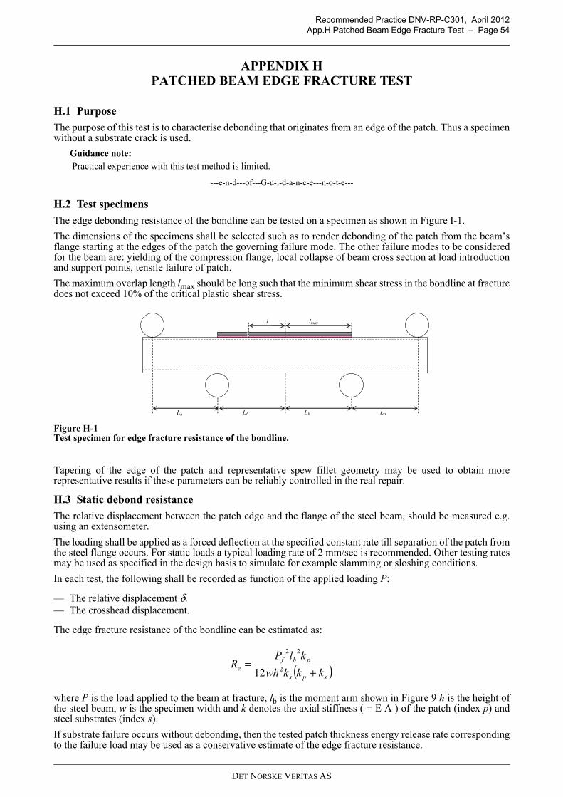
Recommended Practice DNV-RP-C301, April 2012App.H Patched Beam Edge Fracture Test – Page 54
APPENDIX H PATCHED BEAM EDGE FRACTURE TEST
H.1 Purpose
The purpose of this test is to characterise debonding that originates from an edge of the patch. Thus a specimenwithout a substrate crack is used.
Guidance note: Practical experience with this test method is limited.
---e-n-d---of---G-u-i-d-a-n-c-e---n-o-t-e---
H.2 Test specimens
The edge debonding resistance of the bondline can be tested on a specimen as shown in Figure I-1.
The dimensions of the specimens shall be selected such as to render debonding of the patch from the beam’sflange starting at the edges of the patch the governing failure mode. The other failure modes to be consideredfor the beam are: yielding of the compression flange, local collapse of beam cross section at load introductionand support points, tensile failure of patch.
The maximum overlap length lmax should be long such that the minimum shear stress in the bondline at fracturedoes not exceed 10% of the critical plastic shear stress.
Figure H-1 Test specimen for edge fracture resistance of the bondline.
Tapering of the edge of the patch and representative spew fillet geometry may be used to obtain morerepresentative results if these parameters can be reliably controlled in the real repair.
H.3 Static debond resistance
The relative displacement between the patch edge and the flange of the steel beam, should be measured e.g.using an extensometer.
The loading shall be applied as a forced deflection at the specified constant rate till separation of the patch fromthe steel flange occurs. For static loads a typical loading rate of 2 mm/sec is recommended. Other testing ratesmay be used as specified in the design basis to simulate for example slamming or sloshing conditions.
In each test, the following shall be recorded as function of the applied loading P:
— The relative displacement δ.— The crosshead displacement.
The edge fracture resistance of the bondline can be estimated as:
where P is the load applied to the beam at fracture, lb is the moment arm shown in Figure 9 h is the height ofthe steel beam, w is the specimen width and k denotes the axial stiffness ( = E A ) of the patch (index p) andsteel substrates (index s).
If substrate failure occurs without debonding, then the tested patch thickness energy release rate correspondingto the failure load may be used as a conservative estimate of the edge fracture resistance.
La La Lb Lb
l lmax
( )sps
pbfe kkkwh
klPR
+=
2
22
12
DET NORSKE VERITAS AS
Recommended Practice DNV-RP-C301, April 2012App.H Patched Beam Edge Fracture Test – Page 55
H.4 Fatigue debond growthThe bondline fatigue debonding resistance can be measured with the same test configuration as that used forbondline damage resistance characterisation with the maximum overlap length, however, subjected to aconstant amplitude cyclic loading with loading ratio R>0. The loading frequency shall be less than 4 Hz.The extensometer displacement amplitude shall be recorded as function of cycle number.The position of the debonding crack tip shall be recorded at regular intervals. The crack tip position should belocated by close visual inspection.If using an optical measurement system, location of the crack tip should be attempted by looking forsingularities in the strain or deformation field in the bondline. The crack tip location found by the optical systemshould be correlated with that from visual inspection. For each adhesive system, patch laminate and test condition (e.g. temperature), the crack growth rate da/dNshall be tabulated for each load level together with the fracture loading ΔJ corresponding to that loading level.The crack growth rate shall be plotted as a function of the fracture loading in a log-log scale. If a linearrelationship is observed for the intermediate range of loading most relevant to the repair, the slope of that linearsegment defines μ. The factor C is obtained as the intersection with the vertical coordinate axis of a lineextending from this linear segment.
H.5 Bondline stress rupture The bondline stress rupture resistance can be measured with the same test configuration as that used forbondline damage resistance characterisation with the maximum overlap length, however, subjected to asustained constant loading. The extensometer displacement shall be recorded as function of time.The occurrence of a possible debonding crack shall be monitored, and if present, the position of the tip shall berecorded at regular intervals. The crack tip position should be located by close visual inspection.If using an optical measurement system, the existence of a crack and the location of its tip should be attemptedverified by looking for singularities in the strain or deformation field in the bondline. The survival time till stress rupture shall be recorded for the specimens that rupture within the specifiedmaximum test duration.For each adhesive system, patch laminate and test condition (e.g. temperature), the survival time tabulated foreach load level together with the fracture loading ΔJ corresponding to that loading level. The survival time shallbe plotted as a function of the fracture loading in a log-log scale.
DET NORSKE VERITAS AS
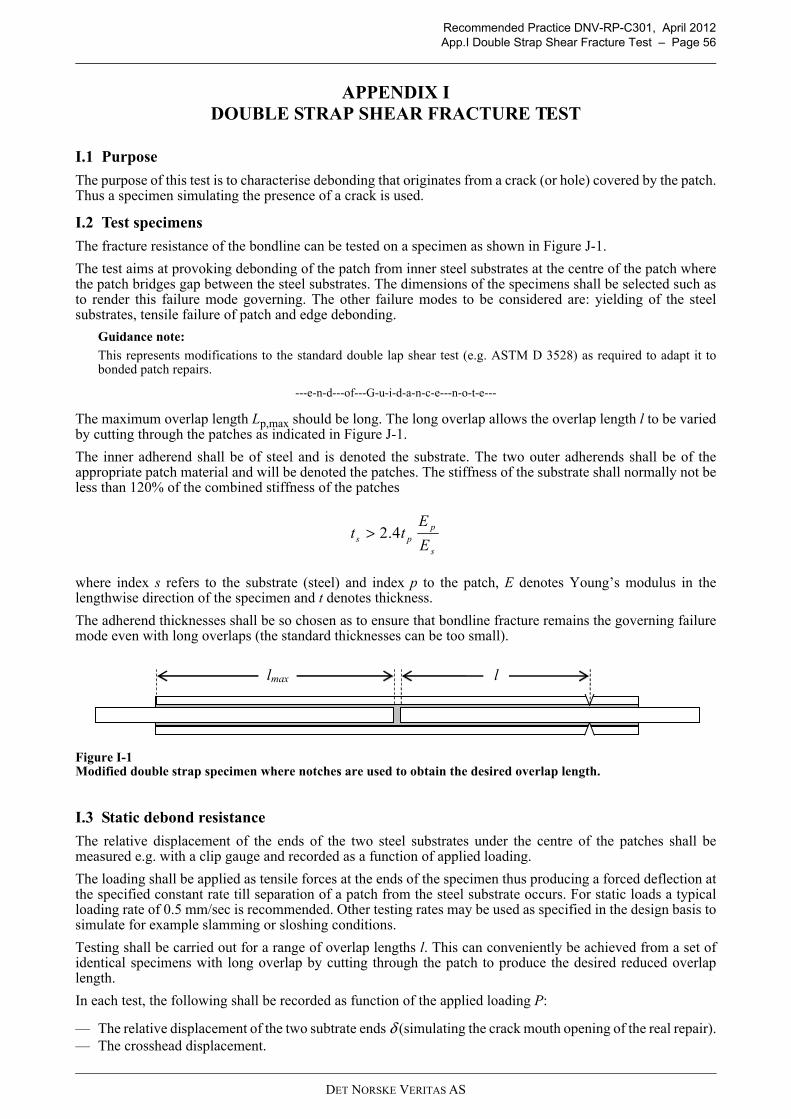
Recommended Practice DNV-RP-C301, April 2012App.I Double Strap Shear Fracture Test – Page 56
APPENDIX I DOUBLE STRAP SHEAR FRACTURE TEST
I.1 Purpose
The purpose of this test is to characterise debonding that originates from a crack (or hole) covered by the patch.Thus a specimen simulating the presence of a crack is used.
I.2 Test specimens
The fracture resistance of the bondline can be tested on a specimen as shown in Figure J-1.
The test aims at provoking debonding of the patch from inner steel substrates at the centre of the patch wherethe patch bridges gap between the steel substrates. The dimensions of the specimens shall be selected such asto render this failure mode governing. The other failure modes to be considered are: yielding of the steelsubstrates, tensile failure of patch and edge debonding.
Guidance note:
This represents modifications to the standard double lap shear test (e.g. ASTM D 3528) as required to adapt it tobonded patch repairs.
---e-n-d---of---G-u-i-d-a-n-c-e---n-o-t-e---
The maximum overlap length Lp,max should be long. The long overlap allows the overlap length l to be variedby cutting through the patches as indicated in Figure J-1.
The inner adherend shall be of steel and is denoted the substrate. The two outer adherends shall be of theappropriate patch material and will be denoted the patches. The stiffness of the substrate shall normally not beless than 120% of the combined stiffness of the patches
where index s refers to the substrate (steel) and index p to the patch, E denotes Young’s modulus in thelengthwise direction of the specimen and t denotes thickness.
The adherend thicknesses shall be so chosen as to ensure that bondline fracture remains the governing failuremode even with long overlaps (the standard thicknesses can be too small).
Figure I-1 Modified double strap specimen where notches are used to obtain the desired overlap length.
I.3 Static debond resistance
The relative displacement of the ends of the two steel substrates under the centre of the patches shall bemeasured e.g. with a clip gauge and recorded as a function of applied loading.
The loading shall be applied as tensile forces at the ends of the specimen thus producing a forced deflection atthe specified constant rate till separation of a patch from the steel substrate occurs. For static loads a typicalloading rate of 0.5 mm/sec is recommended. Other testing rates may be used as specified in the design basis tosimulate for example slamming or sloshing conditions.
Testing shall be carried out for a range of overlap lengths l. This can conveniently be achieved from a set ofidentical specimens with long overlap by cutting through the patch to produce the desired reduced overlaplength.
In each test, the following shall be recorded as function of the applied loading P:
— The relative displacement of the two subtrate ends δ (simulating the crack mouth opening of the real repair).— The crosshead displacement.
s
pps E
Ett 4.2>
lmax l
DET NORSKE VERITAS AS
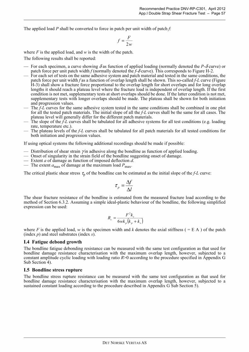
Recommended Practice DNV-RP-C301, April 2012App.I Double Strap Shear Fracture Test – Page 57
The applied load P shall be converted to force in patch per unit width of patch f:
where F is the applied load, and w is the width of the patch.The following results shall be reported:
— For each specimen, a curve showing δ as function of applied loading (normally denoted the P-δ curve) orpatch force per unit patch width f (normally denoted the f-δ curve). This corresponds to Figure H-2.
— For each set of tests on the same adhesive system and patch material and tested in the same conditions, thepatch force per unit width f as a function of overlap length shall be shown. This so-called f-L curve (FigureH-3) shall show a fracture force proportional to the overlap length for short overlaps and for long overlaplengths it should reach a plateau level where the fracture load is independent of overlap length. If the firstcondition is not met, supplementary tests at short overlaps should be done. If the latter condition is not met,supplementary tests with longer overlaps should be made. The plateau shall be shown for both initiationand progression values.
— The f-L curves for the same adhesive system tested in the same conditions shall be combined in one plotfor all the tested patch materials. The initial slope of all the f-L curves shall be the same for all cases. Theplateau level will generally differ for the different patch materials.
— The slope of the f-L curves shall be tabulated for all adhesive systems for all test conditions (e.g. loadingrate, temperature etc.).
— The plateau levels of the f-L curves shall be tabulated for all patch materials for all tested conditions forboth initiation and progression values.
If using optical systems the following additional recordings should be made if possible:
— Distribution of shear strain γ in adhesive along the bondline as function of applied loading.— Onset of singularity in the strain field of the bondline suggesting onset of damage.— Extent a of damage as function of imposed deflection d.— The extent amax of damage at the maximum load Pmax.
The critical plastic shear stress τp of the bondline can be estimated as the initial slope of the f-L curve:
The shear fracture resistance of the bondline is estimated from the measured fracture load according to themethod of Section 6.3.2. Assuming a simple ideal-plastic behaviour of the bondline, the following simplifiedexpression can be used:
where F is the applied load, w is the specimen width and k denotes the axial stiffness ( = E A ) of the patch(index p) and steel substrates (index s).
I.4 Fatigue debond growthThe bondline fatigue debonding resistance can be measured with the same test configuration as that used forbondline damage resistance characterisation with the maximum overlap length, however, subjected to aconstant amplitude cyclic loading with loading ratio R>0 according to the procedure specified in Appendix GSub Section 4).
I.5 Bondline stress ruptureThe bondline stress rupture resistance can be measured with the same test configuration as that used forbondline damage resistance characterisation with the maximum overlap length, however, subjected to asustained constant loading according to the procedure described in Appendix G Sub Section 5).
w
Ff
2=
l
fp Δ
Δ=τ
( )spp
sc kkwk
kFR
+=
6
2
DET NORSKE VERITAS AS
Recommended Practice DNV-RP-C301, April 2012App.J Double Strap Edge Fracture Test – Page 58
APPENDIX J DOUBLE STRAP EDGE FRACTURE TEST
J.1 PurposeThe purpose of this test is to characterise debonding that originates from an edge of the patch. Thus a specimenwithout a crack is used.
J.2 Test specimensThe test specimen consists of a steel substrate with composite patches bonded on both sides. The steel substrateis continuous through the whole specimen.
Figure J-1 Figure 14 Modified double strap specimen with continuous steel substrate.
The specimen should if possible be so designed as to render edge debonding the governing failure mode. Theother failure mode to consider is yield in tension of the substrate. It may be necessary to use rather thicksubstrate and patches. If the test fails to produce edge debonding, then the bondline can be regarded to be qualified for patch andsubstrate thicknesses equal to or less than those tested.Tapering of the edge of the patch and representative spew fillet geometry may be used to obtain morerepresentative results if these parameters can be reliably controlled in the real repair.Substrate thickness should not be less that that used for the repair.
J.3 StaticThe relative displacement between the patch and the steel substrate beam, should be measured e.g. using anextensometer.The loading shall be applied as a forced deflection at the specified constant rate till separation of the patch fromthe steel flange occurs. For static loads a typical loading rate of 0.5 mm/s is recommended. Other testing ratesmay be used as specified in the design basis to simulate for example slamming or sloshing conditions.In each test, the following shall be recorded as function of the applied loading P:
— The relative displacement δ.— The crosshead displacement.
The applied load P shall be converted to force in patch per unit width of patch f. If an optical system is used to measure deformations, it is recommended to record the following:
— Distribution of shear strain γ in adhesive along the bondline as function of applied loading.— Onset of singularity in the strain field of the bondline suggesting onset of damage.— Extent a of damage as function of imposed deflection d.— The extent amax of damage at the maximum load Pmax.
If edge debonding is observed, the edge fracture resistance can be estimated from:
where F is the applied load, w is the specimen width and k denotes the axial stiffness ( = E A ) of the patch(index p) and steel substrates (index s). If substrate failure occurs without debonding, then the energy release rate corresponding to the failure load maybe used as a conservative estimate of the edge fracture resistance.
J.4 Fatigue debond growthThe bondline fatigue debonding resistance can be measured with the same test configuration as that used forbondline damage resistance characterisation with the maximum overlap length, however, subjected to aconstant amplitude cyclic loading with loading ratio R>0 according to the procedure described in Section 4).
2lo
( )sps
pe kkwk
kFR
+=
6
2
DET NORSKE VERITAS AS

Recommended Practice DNV-RP-C301, April 2012App.J Double Strap Edge Fracture Test – Page 59
J.5 Bondline stress rupture The bondline stress rupture resistance can be measured with the same test configuration as that used forbondline damage resistance characterisation with the maximum overlap length, however, subjected to asustained constant loading according to the procedure described in Section 5).
DET NORSKE VERITAS AS

Recommended Practice DNV-RP-C301, April 2012App.K Blister Fracture Resistance Test – Page 60
APPENDIX K BLISTER FRACTURE RESISTANCE TEST
The bondline blister fracture resistance for patches subjected to pressure loading can be measured on a platesubstrate with a hole or slit that is patched on both sides of the plate. Sketches of possible specimen geometriesare given in Figure L-1.
Figure K-1 Blister test configurations.
A pressure P is introduced in-between the patches. The pressure and deflection of the patch are measured.An energy balance approach similar to that used for edge and central shear fracture can be used to determinethe appropriate blister fracture resistance.
Guidance note: At present there is little or no experience with such testing. However, a similar method is used successfully for pipessee e.g. ISO working draft ISO/PDTS 24817 (full reference in Section 1).
---e-n-d---of---G-u-i-d-a-n-c-e---n-o-t-e---
P P
DET NORSKE VERITAS AS

Recommended Practice DNV-RP-C301, April 2012App.L Idealised Fracture Toughness Tests – Page 61
APPENDIX L IDEALISED FRACTURE TOUGHNESS TESTS
L.1 GeneralIdealised fracture toughness tests may be used to characterise the bondline fracture properties. A selection ofsuch tests is given in Table M-1. The interpretation of test data and use of results would depend on the particulartheoretical model used to predict the repair capacity. Particular care should be taken with regard to the following issues:
— The definition used to identify initial and progressive values of fracture toughness.— The influence of fibre bridging, friction and inelastic deformations on the test results and how this should
be translated into the theoretical model.
In general, the compatibility of the theoretical model with the tests procedure and interpretation of the testresults used must be documented. This is not covered herein for the tests in this sub-section.The starter crack shall be obtained by fatigue. This can be achieved by putting a thin non-adhering plastic layeracross the width of the metal adhesive interface, before the adhesive is applied. A small number of fatigue loadcycles is usually enough to make the crack propagate a bit, creating a natural crack tip. The crack length shall be measured on both sides of the specimen and an average value shall be used for thefracture toughness calculations.The testing rate shall be 2 mm/sec. Other testing rates may be specified in addition to simulate for exampleslamming or sloshing conditions.To ensure that the laminate or laminate adhesive interface does not provide a weak link in the system, thelaminate should be similar to the one used in the actual application. However, some modifications areacceptable, such as the use of doublers to avoid failure of the laminate adherend during testing. The referencesin Section 1.9 may be consulted for further details.Characteristic values of fracture toughness shall be calculated from the measured dataset according to DNV-OS-C501.If the adhesive layer is thicker than 0.3 mm another test series with the starter crack between the laminate andthe adhesive shall be performed.References to papers discussing the parameters affecting the Mode II fracture toughness are given in Section 1.9.
DET NORSKE VERITAS AS
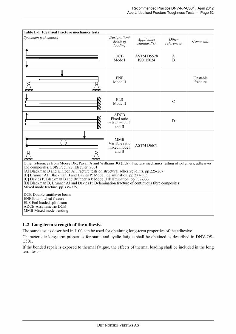
Recommended Practice DNV-RP-C301, April 2012App.L Idealised Fracture Toughness Tests – Page 62
L.2 Long term strength of the adhesiveThe same test as described in I100 can be used for obtaining long-term properties of the adhesive.Characteristic long-term properties for static and cyclic fatigue shall be obtained as described in DNV-OS-C501.If the bonded repair is exposed to thermal fatigue, the effects of thermal loading shall be included in the longterm tests.
Table L-1 Idealised fracture mechanics testsSpecimen (schematic) Designation/
Mode of loading
Applicable standard(s)
Other references Comments
DCBMode I
ASTM D5528ISO 15024
AB
ENFMode II
Unstable fracture
ELSMode II C
ADCBFixed ratio
mixed mode I and II
D
MMBVariable ratio mixed mode I
and II
ASTM D6671
Other references from Moore DR, Pavan A and Williams JG (Eds), Fracture mechanics testing of polymers, adhesives and composites, ESIS Publ. 28, Elsevier, 2001 [A] Blackman B and Kinloch A: Fracture tests on structural adhesive joints. pp 225-267 [B] Brunner AJ, Blackman B and Davies P: Mode I delamination. pp 277-305 [C] Davies P, Blackman B and Brunner AJ: Mode II delamination. pp 307-333 [D] Blackman B, Brunner AJ and Davies P: Delamination fracture of continuous fibre composites: Mixed mode fracture. pp 335-359
DCB Double cantilever beam ENF End notched flexure ELS End loaded split beamADCB Assymmetric DCB MMB Mixed mode bending
DET NORSKE VERITAS AS