DNA OLIGONUCLEOTIDE SYNTHESIS IN A MICRODEVICE FOR ... · dna oligonucleotide synthesis in a...
133
DNA OLIGONUCLEOTIDE SYNTHESIS IN A MICRODEVICE FOR MULTIPLE ANALYTICAL APPLICATIONS WANG CHEN (B. Eng, Zhejiang University) A THESIS SUBMITTED FOR THE DEGREE OF DOCTOR OF PHILOSOPHY DIVISION OF BIOENGINEERING NATIONAL UNIVERSITY OF SINGAPORE 2010
Transcript of DNA OLIGONUCLEOTIDE SYNTHESIS IN A MICRODEVICE FOR ... · dna oligonucleotide synthesis in a...

DNA OLIGONUCLEOTIDE SYNTHESIS IN A MICRODEVICE FOR
MULTIPLE ANALYTICAL APPLICATIONS
WANG CHEN
(B. Eng, Zhejiang University)
A THESIS SUBMITTED
FOR THE DEGREE OF DOCTOR OF PHILOSOPHY
DIVISION OF BIOENGINEERING
NATIONAL UNIVERSITY OF SINGAPORE
2010

i
Acknowledgements
First of all, I would like to express my sincere gratitude to my supervisor, Dr. Dieter Trau
for his guidance and support over the course of my Ph.D. study. He has taught me how to
think critically and conduct research independently. His financial support during the last
year of my study helped me pass the most difficult time.
I would like to thank all my lab mates in Nanobioanalystics Lab. Especially, Dr. Mak
Wing Cheung and Ms. Cheung Kwan Yee have taught me a lot of research techniques at
the early stage of my study and gave me a lot of valuable suggestion through the course
of my study. Mr. Bai Jianhao helped me revise my manuscript and suggest me several
good experiments. Ms. Lee Yee Wei helped me purchase everything used in my study.
I would also like to thank Dr. Partha Roy for providing me the photolithography facilities
and A/P Zhang Yong for allowing me use the oxygen plasma machine. I also thank Dr.
Shakil Rehman for his guide on optical detection.
I would also like to thank National University of Singapore for providing me Research
Scholarship for the first four years of my study.

ii
I would also like to thank Ministry of Defence of Singapore. This project is fully
supported by research grant provided by Ministry of Defence. I was also financially
supported by the research grant in the last year of my study. Without this support, this
research cannot be accomplished.
Last but not the least; I would like to thank my family who has always been there for me.
I appreciate the continuous love and encouragement from my parents. Above all, I thank
my wife Wu Liqun for her patience, understanding and unending love. During my most
difficult period, she encouraged me to continue and not give up. She also gave me
unconditional support for all decision I made. Without her accompanying me, this study
could not be completed.

iii
Table of Contents
ACKNOWLEDGEMENTS ················································································································ I
TABLE OF CONTENTS ················································································································· III
SUMMARY ········································································································································ VI
LIST OF TABLES ························································································································· VIII
LIST OF FIGURES ·························································································································· IX
ABBREVIATIONS ·························································································································· XII
CHAPTER 1 INTRODUCTION ······································································································· 1
1.1 Background ············································································································· 2
1.1.1 DNA oligonucleotide ························································································ 2
1.1.2 Microfluidic device ··························································································· 4
1.1.3 Combine oligonucleotide synthesis with microfluidic technologies ················· 5
1.2 Scope and specific aims of study ············································································· 5
CHAPTER 2 LITERATURE REVIEW··························································································· 7
2.1 DNA oligonucleotide synthesis ··············································································· 8
2.1.1 Synthesis chemistry ·························································································· 8
2.1.1.1 Phosphodiester approach ········································································· 10
2.1.1.2 Phosphotriester approach ········································································· 10
2.1.1.3 H-phosphonate approach ········································································· 11
2.1.1.4 Phosphoramidite approach ······································································· 12
2.1.2 Solid phase synthesis ······················································································ 13
2.1.2.1 Solid supports for oligonucleotide synthesis ············································ 15
2.1.2.2 Oligonucleotide synthesizer ····································································· 17
2.1.2.3 In situ oligonucleotide synthesis ······························································ 18
2.2 Microfluidic valve ································································································· 20
2.2.1 Passive and active microvalves ······································································· 20
2.2.2 Pneumatically actuated microvalves ······························································· 22
2.2.2.1 Pneumatic diaphragm microvalve ···························································· 23
2.2.2.2 Pneumatic in-line microvalve ·································································· 26
2.3 Oligonucleotide synthesis in a microfluidic device ················································ 28
2.3.1 Microfluidic device reactor ············································································· 28
2.3.2 Microfluidic oligonucleotide synthesizer ························································ 29

iv
CHAPTER 3 ZERO DEAD-VOLUME MICROVALVE ···························································· 31
3.1 Introduction ··········································································································· 32
3.2 Microvalves design and fabrication ······································································· 35
3.2.1 Zero dead-volume microvalve design ····························································· 35
3.2.2 Microvalve working principles ······································································· 37
3.2.3 Microvalve fabrication ···················································································· 37
3.2.3.1 Master fabrication and PDMS micromolding ·········································· 37
3.2.3.2 PDMS membrane fabrication ··································································· 38
3.2.3.3 Microvalve fabrication ············································································· 40
3.3 Result and discussion····························································································· 43
3.3.1 Microvalve characterization ············································································ 43
3.3.1.1 Microvalve operation ··············································································· 43
3.3.1.2 Leakage pressure ····················································································· 46
3.3.2 Zero dead-volume ··························································································· 47
3.3.3 Minimal cross contamination tested by PCR ·················································· 49
3.4 Conclusion ············································································································· 53
CHAPTER 4 OLIGONUCLEOTIDE SYNTHESIS IN A PORTABLE SYNTHESIZER ···· 54
4.1 Introduction ··········································································································· 55
4.2 Portable oligonucleotide synthesizer ····································································· 57
4.2.1 Software ········································································································· 57
4.2.2 Hardware ········································································································ 59
4.2.3 System integration ·························································································· 60
4.2.4 Microvalve assignment ··················································································· 62
4.3 Materials and methods ··························································································· 62
4.3.1 Chemicals ······································································································· 62
4.3.2 Synthesis reactor ····························································································· 63
4.3.2.1 Reactor for primer synthesis on CPG ······················································· 63
4.3.2.2 Reactor for probe synthesis on glass slide ················································ 64
4.3.3 Surface modification of microscope glass slides ············································· 65
4.3.4 Oligonucleotide synthesis protocol ································································· 66
4.3.5 PAGE and PCR ······························································································· 67
4.3.6 Probe deprotection and hybridization ····························································· 68
4.4 Result and discussion····························································································· 69
4.4.1 PCR primer synthesis ····················································································· 69

v
4.4.2 Probe synthesis ······························································································· 72
4.4.2.1 Probe for oligonucleotide hybridization ··················································· 72
4.4.2.2 Probe for single-base mismatch differentiation ········································ 73
4.5 Conclusion ············································································································· 75
CHAPTER 5 PORTABLE GENERIC DNA HYBRIDIZATION BIOASSAY SYSTEM ······ 76
5.1 Introduction ··········································································································· 77
5.2 System design ········································································································ 78
5.2.1 Texas Red fluorescence detection system ······················································· 78
5.2.2 Integration of fluorescence detection and oligonucleotide synthesis system ··· 79
5.2.2.1 Modified microfluidic chip ······································································ 80
5.2.2.2 Reactor for oligonucleotide synthesis and hybridization ·························· 81
5.2.2.3 Portable DNA bioassay system ································································ 83
5.3 Materials and methods ··························································································· 85
5.3.1 Hybridization probe immobilization on glass slide ········································· 85
5.3.2 Asymmetric PCR ···························································································· 85
5.3.3 DNA hybridization ························································································· 86
5.4 Result and discussion····························································································· 86
5.4.1 Fluorescence detection system ········································································ 86
5.4.1.1 System characterization ··········································································· 86
5.4.1.2 Detection of complementary and single-base mismatch DNA hybridization ····························································································································· 88
5.4.2 Bacterial differentiation ·················································································· 90
5.5 Conclusion ············································································································· 93
CHAPTER 6 CONCLUSION ·········································································································· 94
6.1 Conclusion and original contributions ··································································· 95
6.2 Technical challenges ······························································································ 98
6.3 Future works ·········································································································· 99
BIBLIOGRAPHY ···························································································································· 101
APPENDIX A LIST OF COMPONENTS FOR THE PORTABLE SYSTEM ······················ 114
APPENDIX B ASSIGNMENT OF NI 9476 ················································································· 116
APPENDIX C SPECTRUM OF OPTICAL PARTS FOR FLUORESCENCE DETECTION ····························································································································································· 117
APPENDIX D LIST OF PUBLICATIONS ·················································································· 119

vi
Summary
DNA Oligonucleotide, a short piece of DNA, is one of the most commonly used materials
in biomolecular applications. Nowadays, most oligonucleotides are synthesized in
commercialized oligonucleotide synthesizers. Due to the complexity of the synthesis
process, these synthesizers are bulky in size. Recently, there is an emerging need of on-
site applications of oligonucleotides, such as in civil defense to immediately detect
biological attacks. However, due to the size limitation of the available oligonucleotide
synthesizers, only pre-made oligonucleotides with certain sequence can be brought to the
field. It is practically impossible to get oligonucleotide of any sequence on demand in the
field. In this thesis, a solution is offered by proposing and building a portable
oligonucleotide synthesizer based on microfluidic technology.
Firstly, a microfluidic chip with integrated microvalves is developed. The microvalves
have zero dead-volume characteristic that is attributed to the design of zigzag shaped
main channel and special position of each microvalve. This design removes the
connecting channels between the microvalve and the main channel that are usually found
in traditional designs. Therefore, reagents cannot be trapped within the microfluidic
device and cross contamination can be effectively minimized. The zero dead-volume
characteristic is proven by detection of trace amount of DNA template molecules trapped
in the device. This contamination free characteristic is extremely important for
applications, such as DNA oligonucleotide synthesis, in which cross contamination is

vii
critical issue and can lead to failure of the synthesis.
Secondly, a portable oligonucleotide synthesizer based on the developed zero dead-
volume microchip is built. The portable synthesizer has the ability to synthesize
oligonucleotide as either primer or probe. The sequence and biological functionality of
the synthesized oligonucleotides are proven by polyacrylamide gel electrophoresis, PCR
and DNA hybridization experiment. The portable synthesizer has the ability to synthesize
oligonucleotide of any sequence on demand. To the best of our knowledge, this is the first
reported portable oligonucleotide synthesizer.
To further improve the function of the portable system and realize generic DNA bioassay
within it, a DNA hybridization and fluorescence detection unit is presented and integrated
into the portable synthesizer. The fully integrated system, a portable generic DNA
hybridization bioassay system, is successfully used to distinguish different bacteria
strains based on in situ DNA oligonucleotide synthesis, hybridization and fluorescence
detection. As far as we know, this is also the first portable generic DNA bioassay system
reported. As the system has the potential to detect DNA target of any sequence in the field,
we envisage that the system could help to enable fast responses to emerging bio-threats
for homeland security and in pandemics.

viii
List of Tables
Table 2-1 Reaction scheme of different oligonucleotide synthesis approaches, their inherent problems and their contributions to the development of oligonucleotide synthesis chemistry ............................................................................................................................. 9
Table 2-2 Categorization of active microvalves ............................................................... 22
Table 4-1 Reagents and reaction time for oligonucleotide synthesis ................................ 67
ix
List of Figures
Figure 2-1 Chemical structures of deoxyribonucleotide phosphoramidites. The protecting groups are labeled in different colors: Red color: acid-labile DMT group to protect 5’-OH. Blue color: 2-cyanoethyl group to protect phosphite. Green color: isobutyryl or benzoyl group to protect exocyclic amino group. .......................................................................... 13
Figure 2-2 Scheme of solid phase oligonucleotide synthesis. Four reactions are involved in one synthesis cycle: detritylation, coupling, oxidation and capping. ........................... 15
Figure 2-3 Schematic illustrating the working principle of the pneumatically actuated diaphragm microvalve. (a) The microvalve is closed when positive pressure is applied through the pneumatic port. (b) The microvalve is opened when negative pressure is applied, causing the formation of a connecting channel between the thin membrane and the valve seat. .................................................................................................................... 24
Figure 2-4 Schematic illustrating the working principle of pneumatically actuated inline microvalve. (a) Microvalve is open at rest. (b) Microvalve is closed when positive pressure is applied through the pneumatic channel. The thin fluidic layer is pushed down to close the valve. .............................................................................................................. 27
Figure 3-1 Traditional design of multiple valves integrated microfluidics (a) All inlets are distributed along the main channel. (b) All inlets merge into the main channel at one point. ........................................................................................................................................... 33
Figure 3-2 Virtual valve designed by Braschler and co-workers. The process of switching from reagent B to reagent A. No cross contamination from reagent B is observed after fully switching to reagent A. ............................................................................................. 34
Figure 3-3 Design of the microvalves integrated microfluidic device with zero dead-volume characteristic. The main channel is zigzag shaped. The microvalves are positioned at each turning point of the main channel. ...................................................... 36
Figure 3-4 Thickness of PDMS membranes vs. spin speed. 2 ml PDMS was applied on the silicon wafer. ............................................................................................................... 40
Figure 3-5 Schematic diagram depicting the fabrication process of the microvalve (a) PDMS fluidic layer fabricated by micromolding and fabricated PDMS thin membrane. (b) Permanent bonding of fluidic layer and thin membrane by treating them with oxygen plasma. The valve seat is covered to avoid bonding with the thin membrane. (c) Peal off the fluidic layer-thin membrane complex after baking and then permanent bonding with pneumatic layer (fabricated also by micromolding) by treating with oxygen plasma. (d) The device is ready to use after baking for overnight. ...................................................... 42
Figure 3-6 Fabricated microvalves integrated microfluidic chip ...................................... 43
x
Figure 3-7 Photograph of the microvalve. (a) The microvalve is closed by external positive pressure through pneumatic channel. (b) The microvalve is opened by external negative pressure through pneumatic channel. ................................................................. 45
Figure 3-8 Relationship between valve closing pressure and leakage pressure of the fabricated microvalve ........................................................................................................ 47
Figure 3-9 Photograph of the microvalve showing the zero dead-volume characteristic; two colored liquids (green and red) are used for illustration. (a) The microvalve that controls green liquid was opened. (b) The microvalve that controls green liquid was closed and another microvalve (located at upstream of the main channel) that controls red liquid was opened. No contamination of the red liquid from the green liquid was observed. ........................................................................................................................................... 49
Figure 3-10 Trace amount of DNA template molecules detection by PCR and gel electrophoresis. Lane 1: 100 bp DNA ladder; Lane 2-5: positive control with PCR starting from 1000, 100, 10 and 0 template molecules; Lane 6-8: PCR with effluent after washing for 10 s, 20 s and 30 s. (a) Our microvalve design (b) Traditional microvalve design ..... 52
Figure 4-1 Screen shots of the software for controlling oligonucleotide synthesis. The software was programmed under LabVIEW. (a) The information input interface (b) The synthesis monitoring interface. ......................................................................................... 58
Figure 4-2 System design and photograph of portable oligonucleotide synthesizer (a) Schematic diagram illustrating the complete system, including electrical and electronic parts, fluidic parts and pneumatic parts. Only four microvalves are shown on the diagram for simplicity. (b) Photograph of the portable oligonucleotide synthesizer: (1) PC (2) Argon tank (3) USB-DAQ (4) Solenoid valves and manifold (5) Pressure regulators (6) Vacuum pump (7) Batteries (8) Microfluidic chip (9) Synthesis reactor (10) Reagents. . 61
Figure 4-3 Assignment of microvalves to oligonucleotide synthesis reagents (1) Washing (2) Argon (3) Activator (4) A (5) T (6) G (7) C (8) Detritylation (9) Oxidation. .............. 62
Figure 4-4 Reactor for oligonucleotide primer synthesis. (1) PDMS cube (2) Glass fiber filter (3)(4) FEP tubing (5) CPG. ...................................................................................... 64
Figure 4-5 Reactor for oligonucleotide probe synthesis. (1) Top acrylic cover with tubing access holes (2) PDMS microchannel (3) Surface modified microscope glass slide (4) Bottom acrylic case. .......................................................................................................... 65
Figure 4-6 Scheme of surface modification of microscope glass slide for synthesis of oligonucleotide probe. ....................................................................................................... 66
Figure 4-7 PAGE image for synthesized oligonucleotide length confirmation. Lane 1: oligonucleotide ladder. Lane 2: HPLC purified commercial oligonucleotide with the same sequence. Lane 3: oligonucleotide synthesized by the portable oligonucleotide synthesizer. ........................................................................................................................................... 70

xi
Figure 4-8 The gel electrophoresis image of PCR product. Lane 1: 50bp DNA ladder. Lane 2: positive control with both forward and reverse primer purchased. Lane 3: PCR product amplified by the synthesized oligonucleotide in our portable synthesizer as reverse primer. ................................................................................................................... 71
Figure 4-9 Fluorescence image of 6-FAM labeled complementary DNA hybridized to synthesized probe .............................................................................................................. 72
Figure 4-10 Fluorescence image of the synthesized probe hybridizing with Texas Red labeled oligonucleotide. (a) Complementary sequence. (b) Single-base mismatch. ........ 74
Figure 5-1 (a) Schematic diagram of the Texas Red fluorescence detection system (b) Photograph of the Texas Red fluorescence detection system. .......................................... 80
Figure 5-2 Microfluidic chip for oligonucleotide synthesis and DNA hybridization. (a) Microvalve assignment (1) Washing (2) Argon (3) Activator (4) A (5) T (6) G (7) C (8) Detritylation (9) Oxidation (10) Hybridization. (b) Fabricated microfluidic chip with 10 microvalves integrated. ..................................................................................................... 81
Figure 5-3 Design of oligonucleotide probe synthesis and hybridization reactor. (1) Top acrylic cover with tubing access hole (2) PDMS microchannel (3) PT100 temperature sensor (4) Surface modified glass slide (5) Bottom acrylic case (6) Heating unit with light access hole. The whole assembly was held together by screw and then fixed inside the fluorescence detection box. ............................................................................................... 83
Figure 5-4 Photograph of the portable system: (1) PC with control software (2) Argon tank (3) NI-DAQ (4) Solenoid valves and manifold (5) Pressure regulators (6) Vacuum pump (7) Batteries (8) Microfluidic chip (9) Synthesis and hybridization reactor (10) LED (11) Photodiode (12) Lenses, filters and beam splitter (13) Injection port for hybridization related reagents. .......................................................................................... 84
Figure 5-5 Calibration curve for Texas Red fluorescence detection system. The lower range of the calibration curve (corresponding to amount of Texas Red fluorophore from 0.5 fmol to 12.5 fmol) is enlarged. .................................................................................... 88
Figure 5-6 Fluorescence image of hybridization to immobilized probes for test of fluorescence detection system. (a) Complementary hybridization (b) Single-base mismatch hybridization. .................................................................................................... 90
Figure 5-7 3D bar graph showing the fluorescence signal from specific and cross hybridization between PCR products of two different bacteria strains and synthesized strain specific probes. ........................................................................................................ 92
xii
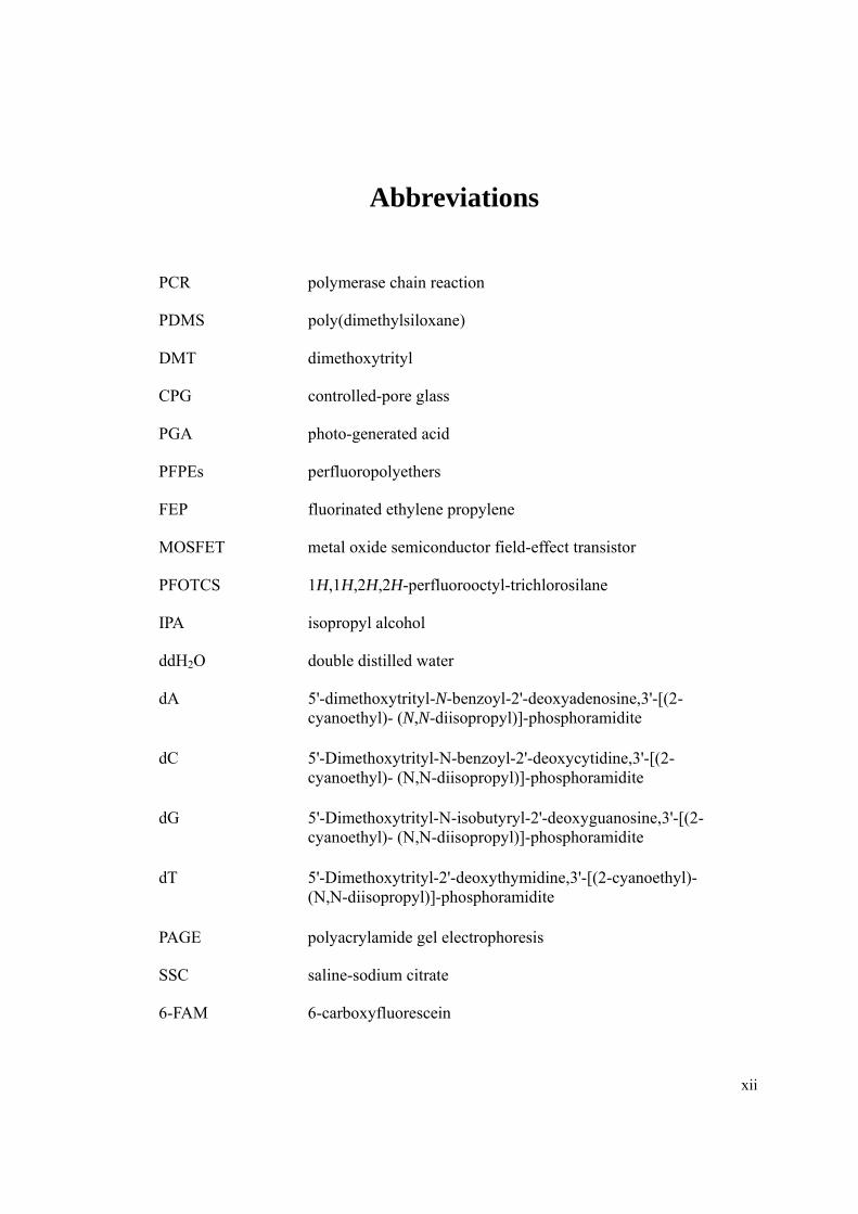
Abbreviations
PCR polymerase chain reaction
PDMS poly(dimethylsiloxane)
DMT dimethoxytrityl
CPG controlled-pore glass
PGA photo-generated acid
PFPEs perfluoropolyethers
FEP fluorinated ethylene propylene
MOSFET metal oxide semiconductor field-effect transistor
PFOTCS 1H,1H,2H,2H-perfluorooctyl-trichlorosilane
IPA isopropyl alcohol
ddH2O double distilled water
dA 5'-dimethoxytrityl-N-benzoyl-2'-deoxyadenosine,3'-[(2-cyanoethyl)- (N,N-diisopropyl)]-phosphoramidite
dC 5'-Dimethoxytrityl-N-benzoyl-2'-deoxycytidine,3'-[(2-cyanoethyl)- (N,N-diisopropyl)]-phosphoramidite
dG 5'-Dimethoxytrityl-N-isobutyryl-2'-deoxyguanosine,3'-[(2-cyanoethyl)- (N,N-diisopropyl)]-phosphoramidite
dT 5'-Dimethoxytrityl-2'-deoxythymidine,3'-[(2-cyanoethyl)- (N,N-diisopropyl)]-phosphoramidite
PAGE polyacrylamide gel electrophoresis
SSC saline-sodium citrate
6-FAM 6-carboxyfluorescein

xiii
TxRd Texas Red
LED light emitting diode
NI National Instruments
DAQ data acquisition
APTES 3-Aminopropyltriethoxysilane
DSS disuccinimidyl suberate
DMF dimethylformamide

1
CHAPTER 1
INTRODUCTION
Chapter 1 Introduction
2
1.1 Background
A DNA oligonucleotide is a single stranded, short fragment of DNA. The length of DNA
oligonucleotide usually ranges from a few bases to 50 bases. However, oligonucleotides
with length around 20 bases are more widely used in biomolecular applications and
studies. Applications for DNA oligonucleotides are widely found in biological studies
such as polymerase chain reaction (PCR) which uses DNA oligonucleotide as a primer to
initiate the PCR reaction [1], DNA microarray which uses DNA oligonucleotide as a
probe for DNA hybridization [2], or gene synthesis which uses DNA oligonucleotide as
the basic building blocks to form the target gene [3]. To obtain oligonucleotide with
desired sequence, chemical synthesis of oligonucleotide by polymerizing individual
nucleotide precursors is commonly used.
1.1.1 DNA oligonucleotide
It has been more than 50 years since the first dimer oligonucleotide was chemically
synthesized [4]. Since then, the research on oligonucleotide synthesis chemistry has been
extensively conducted due to numerous applications for DNA oligonucleotides.
Nowadays, the phosphoramidite method has become the ‘golden standard’ approach for
oligonucleotide synthesis [5]. The essence of this method is polymerizing nucleoside
phosphoramidite one by one according to the required sequence. Several different
chemical reactions, which form a synthesis cycle, take place sequentially. One nucleoside

Chapter 1 Introduction
3
phosphoramidite is added onto the growing chain in one cycle. The synthesis of an
oligonucleotide with specific length and sequence requires the repetition of this synthesis
cycle for a number of times. In Chapter 2, various oligonucleotide synthesis chemistries
and recent improvement will be reviewed.
Nowadays, the oligonucleotide synthesis process has been fully automated. Most
oligonucleotides are synthesized in commercialized oligonucleotide synthesizers [6, 7].
However, due to the complexity of the synthesis process, these synthesizers are bulky in
size. Recently, there is an emerging need of “in the field applications” for
oligonucleotides, such as in civil defense to immediately detect biological attacks.
However, due to the size limitation of the available oligonucleotide synthesizers, only
pre-synthesized oligonucleotides with certain sequence can be brought to the field. It is
practically impossible to get any sequence on demand in the field. This is because, for
example, for a 20-mer oligonucleotide, there are totally 420 (=1.1× 10¹²) possible
sequences, the cost for synthesizing and storing all the possible sequences is tremendous
and increases exponentially with the increase in the length of the oligonucleotide.
Therefore, only selected oligonucleotides can be prepared and brought in the field. As a
consequence, no immediate detection and response to artificially manipulated or naturally
mutated agents harmful to human in the field is possible. Thus, it is absolutely necessary
to develop an oligonucleotide synthesizer in a portable format in order to obtain
oligonucleotide with any required sequence in the field.

Chapter 1 Introduction
4
1.1.2 Microfluidic device
Microfluidic device or Lab-on-a-chip has gained a lot of attention and applications in the
past two decades. Its broad applications in biological and chemical studies such as DNA
analysis [8], cell separation [9], cell culture [10], and material synthesis [11] make it a
dynamic research area. The decrease of fluidic devices in dimension to micrometer scale
leads to the dramatic reduction of the volume to microliter or nanoliter. The small volume
of microfluidic devices reduces the consumption of chemicals and production of waste,
which is environment friendly and cost saving. Furthermore, many reactions can be
carried out simultaneously on a single chip, which increases the throughput [12]. The use
of silicon-based polymers in biological studies such as poly(dimethylsiloxane) (PDMS)
also makes the fabrication process of microfluidic device much easier and cheaper
compared to the use of glass or silicon.
Complicated systems based on microfluidic technologies have been reported [8, 12]. In
these microfluidic systems, often microvalves are an important fundamental element,
which implements the fluids control and manipulation in such devices. By integrating a
number of valves in one microfluidic chip, multiple liquid reagents can be controlled in
sequential or parallel manner as needed. Therefore, applications which require adding a
number of different reagents in a certain sequence can be accomplished within
microfluidic system. In chapter 2, various microvalves based on different actuation
strategies will be reviewed, with more details on pneumatically controlled microvalve.

Chapter 1 Introduction
5
1.1.3 Combine oligonucleotide synthesis with microfluidic technologies
As described, DNA oligonucleotide synthesis is such an application in which a number of
reagents are involved. These reagents need to be added into the reactor chamber in a
sequential manner for a series of reactions to take place. As microfluidic device has the
ability to control and manipulate a number of fluids with the aid of microvalve
technologies, combination of microfluidic technologies and DNA oligonucleotide
synthesis chemistry should provide an easy and efficient way to synthesize DNA
oligonucleotide. The microfluidic system can be then packed into a portable format to
form a portable oligonucleotide synthesizer, which can be used for in the field
applications.
1.2 Scope and specific aims of study
As the project is funded by Ministry of Defence of Singapore (MOD), the overall aim of
the research is to develop a portable DNA oligonucleotide synthesizer for MOD for their
in the field applications. The portable synthesizer should have the ability to synthesize
DNA oligonucleotide of any sequence on demand and the synthesized oligonucleotide
can be used as either primer or probe. Furthermore, the function of the portable system
can be extended to conduct DNA hybridization based bioassay. These aims will be
achieved by accomplishing the following four objectives:

Chapter 1 Introduction
6
1. Develop a microvalves integrated microfluidic device which can control the flow of a
number of reagents, the microfluidic device should minimize cross contamination
among reagents within the device;
2. Integrate the microfluidic device with the electronic and pneumatic controlling units,
and pack them into a portable format to form the portable oligonucleotide synthesizer;
3. Synthesize both DNA oligonucleotide primers and probes within the portable
synthesizer;
4. Design a hybridization and fluorescence detection unit and integrate it into the
portable oligonucleotide synthesizer to conduct generic DNA hybridization based
bioassay.

7
CHAPTER 2
LITERATURE REVIEW
Chapter 2 Literature Review
8
2.1 DNA oligonucleotide synthesis
DNA oligonucleotides are one of the most widely used materials in biomolecular
applications and studies. Till now, almost all oligonucleotides used in those applications
are chemically synthesized. However, researchers spent more than 25 years to find the
satisfactory method to synthesize oligonucleotide. As the development of the computer
technology and process automation, oligonucleotide synthesis has been fully automated
and is carried out in commercialized oligonucleotide synthesizers. In this section,
different oligonucleotide synthesis approaches will be reviewed first, followed by recent
advances in solid phase synthesis and oligonucleotide synthesizer design.
2.1.1 Synthesis chemistry
It has been more than 50 years since the first synthesis of a dithymidine dinucleotide was
reported by Michelson and Todd in 1955 [4]. Since then, extensive research has been
conducted on the chemistry of oligonucleotide synthesis due to numerous applications of
DNA oligonucleotides [2, 13-15]. Different approaches have been invented, including
phosphodiester approach, phosphotriester approach, H-phosphonate approach and
phosphoramidite approach. Among these methods, phosphoramidite approach has
become the standard method and has been dominantly used in the past 20 years. However,
it is necessary to understand all these methods and their respective contribution to the
development of the oligonucleotide synthesis chemistry and inherent problems. Table 2-1

Chapter 2 Literature Review
9
shows a brief summary of all these approaches and they will be reviewed in more details
in the following.
Table 2-1 Reaction scheme of different oligonucleotide synthesis approaches, their
inherent problems and their contributions to the development of oligonucleotide synthesis
chemistry
Approach Coupling Reaction Schemes Problems Contributions
Phosphodiester O
OO
OR
B1P
DMTrO
O
O
B2
O-
+
DMTrO
O
OH
B2
O
O-
O-
O
PO
OR
B2
Branched product, tedious purification
Base and 5’-OH protection, elucidation of genetic code
PhosphotriesterO
OO
O
B1P
DMTrO
O
O
B2
RO
Support
+
DMTrO
O
O
B2
RO O-
O
POH
O
O
B2
Support
Low coupling yield
Phosphate protecting group, initiate solid phase synthesis
H-phosphonate O
OO
O
B1P
DMTrO
O
O
B2
H
Support
+
DMTrO
O
O
B2
H O-
O
POH
O
O
B2
Support
Side reaction, incomplete oxidation
Easy way to get oligonucleotide analogues
PhosphoramiditeO
O
O
B1P
DMTrO
O
O
B2
RO
Support
+
OHO
O
B2
Support
P N
DMTrO
O
O
B2
RO
Water sensitive
Standard approach, automated process,synthesis of long oligonucleotide
Chapter 2 Literature Review
10
2.1.1.1 Phosphodiester approach
In the second half of 1950s, Khorana and his co-workers developed the phosphodiester
approach [16-18]. In the phosphodiester approach, phosphomonoester and the formed
internucleotide phosphodiester are not protected during the coupling reaction, leading to
the problem that oligonucleotides could branch at the internucleotide phosphate.
Therefore, tedious purification is required. Due to these reasons, the phosphodiester
approach was not in use since the 1970s. However, the use of dimethoxytrityl (DMT) as 5’
hydroxyl protecting group [19] and benzoyl and isobutyryl as base protecting group [20]
are very important improvement. These protecting groups are still used in modern
oligonucleotide synthesis (see phosphoramidite approach below). Another contribution
that Khorana has made is the elucidation of genetic code by using this approach to
synthesize short oligomers [21, 22].
2.1.1.2 Phosphotriester approach
In the 1960s, phosphotriester approach was reinvestigated after first reported in 1955 by
Michelson and Todd [4]. Its key difference from the phosphodiester approach is that the
internucleotide phosphate is protected. Therefore, oligonucleotides could not branch at
the internucleotide phosphate. A few protecting groups have been used for protecting the
internucleotide phosphate, including 2-cyanoethyl group [23, 24]. Nowadays this group is
still used in phosphoramidite approach (see below). The problem with this method is that
Chapter 2 Literature Review
11
the coupling efficiency is relatively low, which therefore limits its use in synthesizing
only short oligonucleotide [5]. However, the phosphotriester approach was the first
method used in solid phase synthesis of oligonucleotide [23]. Thereafter, massive
research in this area was initiated and automatic synthesis of oligonucleotide is made
possible due to the success of solid phase synthesis. Nowadays, most of the synthetic
oligonucleotides, if not all, are synthesized by the solid phase approach.
2.1.1.3 H-phosphonate approach
Although first reported by Hall and co-workers in the 1950s [25], this method gained
more attention thirty years later since it was applied to solid phase synthesis of
oligonucleotide [26, 27]. In H-phosphonate approach, only one oxidation reaction is
carried out to convert all the phosphonate diesters to the desired phosphodiesters at the
end of the synthesis (different from phosphoramidite method that oxidation is carried out
in each cycle, see below). The advantage of this method is that only two steps are
involved in one synthesis cycle and oligonucleotide analogues can be easily obtained
during the final oxidation by using different nucleophiles other than water [28, 29].
However, undesired side reaction during coupling and incomplete oxidation in the final
step may lower the final yield of the synthesis. Therefore it is generally accepted that
phosphoramidite approach is superior to H-phosphonate approach in terms of synthesis
efficiency.

Chapter 2 Literature Review
12
2.1.1.4 Phosphoramidite approach
In the 1970s, phosphite triester approach, a revolutionary development in oligonucleotide
synthesis chemistry, was reported [30]. This method was further developed to
phosphoramidite approach a few years later by the introduction of nucleoside
phosphoramidites by Beaucage and Caruthers in 1981 [31]. In this approach, the
phosphite triester linkage [P(III)] is formed first during the coupling reaction and then
oxidized to the desired phosphate triester linkage [P(V)]. This is because that P(III) is
much more reactive than P(V) and therefore more efficient in the formation of
internucleoside linkage [30]. Nowadays, the phosphoramidite approach has become the
‘standard’ method and is dominantly used for oligonucleotide synthesis due to its high
coupling yield (98%) [32]. Almost all automated synthesizers are specially designed for
using phosphoramidite approach. Figure 2-1 shows the chemical structure of
deoxyribonucleotide phosphoramidites which are the basic building blocks used in
phosphoramidite approach. The protecting groups for protection of various functional
groups during oligonucleotide synthesis are labeled in different colors.

Chapter 2 Literature Review
13
2.1.2 Solid phase synthesis
Since first reported by Letsinger and Mahadevan in 1965 [23], enormous research was
carried out on synthesizing oligonucleotide on solid support. In the past 20 years, almost
all commercial oligonucleotides were synthesized in solid phase. In solid phase synthesis
O CH3
OCH3
CN
NH
N
N
NH
O
O
P
O
O
O N
O
N
N-2-isobutryl-deoxyguanosine
phosphoramidite (G)
CH3NH
N
O
O
O
O
O
O CH3
OCH3
PO N
N
Deoxythymidine
phosphoramidite (T)
O
C
N
N
N
N
NH
O
O
O
O CH3
OCH3
PO N
N
N-6-benzoyl-deoxyadenosine
phosphoramidite (A)
N
N
NH
O
O
C
O
O
O
O CH3
OCH3
PO N
N
N-4-benzoyl-deoxycytidine
phosphoramidite (C)
Figure 2-1 Chemical structures of deoxyribonucleotide phosphoramidites. The
protecting groups are labeled in different colors: Red color: acid-labile DMT group to
protect 5’-OH. Blue color: 2-cyanoethyl group to protect phosphite. Green color:
isobutyryl or benzoyl group to protect exocyclic amino group.

Chapter 2 Literature Review
14
of oligonucleotides, one nucleotide is added onto a support-bonded oligonucleotide at a
time till the desired sequence is obtained. Phosphoramidite approach is the most widely
used method for solid phase synthesis of oligonucleotide. In solid phase synthesis by
phosphoramidite approach, a number of reactions forming a synthesis cycle are required
to extend one nucleotide. These reactions include detritylation, coupling, oxidation, and
capping, Excess reagents are usually added in each reaction to achieve higher synthesis
yield and then washed off from the solid support after the reaction is completed [5]. A
point worth noting is that the synthesis direction is from 3’ end to 5’ end, which is
different from the direction of chain extension in natural DNA replication or PCR (5’ end
to 3’ end). The solid phase synthesis technique is a rapid and efficient approach as excess
reagents can be easily removed and thus no tedious and time-consuming purification is
needed after each step. A practical importance of the success of solid phase synthesis is
that it makes the automation of oligonucleotide synthesis become possible. Figure 2-2
shows the reaction scheme of solid phase synthesis of oligonucleotide by using the
phosphoramidite approach.

Chapter 2 Literature Review
15
2.1.2.1 Solid supports for oligonucleotide synthesis
Various materials have been used as the solid support materials in oligonucleotide
synthesis, such as silica gel, controlled-pore glass (CPG) and polystyrene [33-35]. Among
these materials, CPG [34, 36] is still the most widely used support material nowadays.
The pore size of CPG ranges from below 10 nm to several hundred nm. The nucleoside
Figure 2-2 Scheme of solid phase oligonucleotide synthesis. Four reactions are involved
in one synthesis cycle: detritylation, coupling, oxidation and capping.
P
DMTrO
O
O
B1
1. Detritylation
P
OOH
O
B1
NNH
N N
P
OO
O
B1
P
DMTrO
O
O
B2
O
N
P
Abz
Cbz
Gib
or T=
P = Solid Support, e.g., CPG
Start
Reaction Cycle
B1,B2,Bn,Bn+1
P N
DMTrO
O
O
B2
O
N
N
O
OO
O
B1
P
DMTrO
O
O
B2
O
P
O
OO
O
B1
2. Coupling
3. Capping
4. Oxidation
OO
OH
B1
O
P
OO
O
Bn
O-
O
P
OOH
O
O-
n
Bn+1
Cleavage and deprotection

Chapter 2 Literature Review
16
loading decreases with increasing pore size, as the surface area on the CPG decreases
with increasing pore size. However, longer oligonucleotide can be synthesized with larger
pore size due to retaining of high coupling yield when growing strand became longer [37].
The commercialized CPG usually has the first nucleotide attached on the support (see
Figure 2-2 ‘start’). The linkage between CPG and the first base is cleavable [38, 39].
Upon completion of the synthesis, the linkage is cleaved and the oligonucleotide is
released from the CPG. The synthesized oligonucleotide bears 3’ end hydroxyl group,
which is important for oligonucleotide primer to initiate PCR. There are four basic CPG
(A, T, G, or C) available to start the synthesis and one must choose the CPG with the
correct first base according to the 3’ end base of the required sequence (because synthesis
direction was from 3’ end to 5’ end). This undoubtedly causes trouble and increases
possibility of using the wrong CPG. Later on, universal linker chemistry was reported by
various researchers [40-42]. The CPG with universal linker (universal CPG) does not
have the first nucleotide attached on it. Therefore, the same solid support can be used
regardless of the sequence to be synthesized, which is more convenient and reduces
human error possibility. The universal CPG has the similar efficiency for oligonucleotide
synthesis and no modification of synthesis chemistry is needed for using them on
commercial oligonucleotide synthesizer.

Chapter 2 Literature Review
17
2.1.2.2 Oligonucleotide synthesizer
Oligonucleotide synthesis has been fully automated through the development of
oligonucleotide synthesizers. In solid phase synthesis of oligonucleotides, a number of
reagents are added and removed from the solid support in a sequential manner. Therefore,
a valve system which controls the flow of different reagents is the most important part of
an oligonucleotide synthesizer. A column with solid support packed within it is used as
the synthesis reactor. However, the number of oligonucleotide that can be synthesized in
parallel is limited.
Later on, due to the high demand for oligonucleotides in genome-wide studies [43, 44],
high throughput oligonucleotide synthesizers were developed. In the high throughput
synthesizer, 96- and 384-well microplates were both successfully used as the synthesis
reactor [7, 45]. A system consisting of four 384-well microplates has also been developed
to further increase the throughput and has the ability to produce 1536 oligonucleotide at
the same time [7]. However, for such highly parallel synthesis, well-to-well quality
variation of the synthesized oligonucleotides remains a concern. Due to the high
productivity and complexity of system design, all of these synthesizers are bulky in size.
Currently, there are some research conducted on applying microfluidic technology on
oligonucleotide synthesis, this will be reviewed later.

Chapter 2 Literature Review
18
2.1.2.3 In situ oligonucleotide synthesis
In situ oligonucleotide synthesis emerged through the development of DNA microarray
technology. In situ oligonucleotide synthesis has the following advantages. Firstly,
oligonucleotide synthesized on the substrate can be directly used for DNA hybridization;
therefore, no immobilization of pre-synthesized oligonucleotide is required. Secondly, a
large number of different sequences can be synthesized simultaneously at high surface
density.
Several techniques have been used in in situ synthesis of oligonucleotides, including ink-
jet printing [46, 47], micro-contact printing [48], and photolithography [49, 50]. Ink-jet
printing technology has been successfully applied in fabricating microarray [46].
Phosphoramidites were delivered to dedicated location on a glass surface by the ink-jet
printing process. An array of 23,965 oligonucleotides representing human genes was
obtained on an area of 25 × 75 mm2 with 100 µm in diameter per spot. However, the
coupling efficiency was estimated to be 94% to 98%, slightly lower than that of
conventional oligonucleotide synthesis.
Xiao and co-workers used PDMS micro-contact printing technology to synthesize
oligonucleotide microarrays [48]. The synthesized oligonucleotide spots had a feature
size of 90 µm in diameter and 2500 probes were produced in an area of 1 cm2. As many
as 168 different microstamps were made for fabricating the 20-mer oligonucleotide array.

Chapter 2 Literature Review
19
Extra attention must be paid on alignment of the microstamps and the substrate during the
contact printing process to guarantee the quality of the synthesized oligonucleotides. The
solvent compatibility of PDMS with oligonucleotide synthesis reagent was not mentioned
in this study.
In photolithography approach, the 3’ end hydroxyl is deprotected by light instead of acid
as in the phosphoramidite approach. Therefore, a photo-labile protecting group replaced
the traditional acid-labile DMT group. Photomasks [49] or micromirror array [50] were
used to selectively produce the 3’ end hydroxyl at specific location. The synthesized
oligonucleotide spot had a feature size smaller than 25 µm in diameter. The
commercialized Affymetrix® DNA microarray chip is fabricated by this approach.
However, the limitation of this method is that the synthesis efficiency is lower than that
of traditional phosphoramidite chemistry, excluding its use in synthesizing longer
sequences.
To solve the lower synthesis efficiency problem, Gao and co-workers invented the
photogenerated acid (PGA) approach [51, 52]. In this method, standard phosphoramidite
chemistry, i.e., the acid-labile DMT protecting group, is used. The acid to remove the
DMT group is generated by illumination of an acid precursor at selected reaction
chambers. The generated acid then selectively removes the DMT group at specific
chambers. The synthesis must be carried out in a microfluidic device with thousands of

Chapter 2 Literature Review
20
micro chambers integrated instead of on flat substrate surface. When removing the DMT
group, acid diffusion among different reaction chambers must be prevented, otherwise,
the reaction will occur at wrong reaction chambers, leading to undesired oligonucleotide
sequences.
2.2 Microfluidic valve
With the development and aid of microfabrication and micromachining technologies,
microfluidic systems found applications in biological studies and material synthesis [10,
53, 54]. The microfluidic valve is an important component in microfluidic devices. With
microvalves integrated into the microfluidic system, it is possible to manipulate and
control fluid flow within microfluidic devices. In the following sections, the microfluidic
valve technology will be reviewed and the focus is on two types of pneumatically
actuated microvalves, which are widely used in microfluidic biological systems.
2.2.1 Passive and active microvalves
Microvalves can be categorized into two main classes: passive valves and active valves.
Passive valves, or check valves, only open to forward pressure [55-59]. This kind of
valves has diode-like characteristics. The advantage of passive valves is that their design
is relatively simple. However, its main disadvantage is that a leakage flow exists even
under low pressure. This disadvantage excluded the use of such valves in applications

Chapter 2 Literature Review
21
where leakage or cross contamination between reagents is a critical issue and must be
avoided.
Unlike passive valves, active valves can be operated by external means. Therefore, the
valves behavior is not dependent on direction the fluid flow. It is generally accepted that
active microvalves can be categorized into three subgroups according to their actuation
means [60]: mechanical active microvalves, non-mechanical active microvalves and
external active microvalves.
For mechanical active microvalves, the movable membranes are coupled to mechanical
moving parts which can be actuated by different methods such as magnetic, electric,
piezoelectric or thermal means. In contrast, for non-mechanical microvalves, the movable
membranes are actuated by means other than mechanical, e.g., electrochemical reaction
or phase-change materials. For external active microvalves, they are usually actuated by
external systems such as pneumatic pressure (more details in section 2.2.2). A brief list of
the categorization of active microvalves and their respective operation time are
summarized in Table 2-2.

Chapter 2 Literature Review
22
Table 2-2 Categorization of active microvalves
Category Actuation Method
Mechanism Valving Time References
Mechanical
Magnetic Magnetic force 10 ms [61-64]
Electric Electrostatic force ---- [65, 66]
Piezo-electric
Piezoelectric effect < 2 ms [67, 68]
Thermal
Thermal bimetallic actuation or volumetric thermal expansion (thermopneumatic)
bimetallic 0.2 s thermopneumatic > 5 s
bimetallic [69, 70], thermo-pneumatic [71, 72]
Non-mechanical
Electro-chemical
Electrolysis to generate O2 pressure
> 1 min [73, 74]
Phase change
Phase change of hydrogel, sol-gel, or paraffin due to temperature, pH, or light
> 2 s Hydrogel [75-77], Sol-gel[78], paraffin [79, 80]
External Pneumatic External pneumatic pressure
< 5 ms [81-85]
2.2.2 Pneumatically actuated microvalves
Pneumatically actuated microvalves are suitable for biological and chemical applications.
This is due to the reasons that pneumatically actuated microvalves have the advantage of

Chapter 2 Literature Review
23
fast actuation, ease of large-scale integration, no leakage flow and ease of fabrication.
Two types of pneumatically actuated microvalves were previously reported [81, 85], they
are the pneumatic diaphragm microvalve and the pneumatic in-line microvalve.
2.2.2.1 Pneumatic diaphragm microvalve
The pneumatically actuated diaphragm microvalve was first reported by Vieider and co-
workers in 1995 [85]. This microvalve has a three-layer structure. In this design, a
deflectable thin membrane is sandwiched in between a fluidic layer and a pneumatic layer.
The microfluidic channel (on fluidic layer) is interrupted by a valve seat. The working
principle of this type of microvalve is shown in Figure 2-3. The thin membrane is pressed
against the valve seat if a positive pressure (relative to atmospheric pressure) is applied
on the membrane through the pneumatic channel. Under positive pressure, the valve is
closed and liquid is stopped behind the valve seat. On the other hand, if a negative
pressure is applied, the membrane is deflected away from the valve seat and a connecting
channel is formed in between. Under negative pressure, the valve is opened and liquid
can flow over the valve seat.

Chapter 2 Literature Review
24
Figure 2-3 Schematic illustrating the working principle of the pneumatically actuated
diaphragm microvalve. (a) The microvalve is closed when positive pressure is applied
through the pneumatic port. (b) The microvalve is opened when negative pressure is
applied, causing the formation of a connecting channel between the thin membrane and
the valve seat.
The material of the deflectable thin membrane is a key issue in the design of such
microvalve. As the membrane is the only moving part in the microvalve, it should be
flexible, durable and readily sealable against other materials (glass, silicon or other
polymers which are used for fabricating the fluidic and pneumatic layer). The materials
that have been used as the membrane includes silicone membrane [86], 3M tape sheet [87]
and PDMS membrane [88, 89]. The PDMS membrane has been a good choice due to its

Chapter 2 Literature Review
25
low Young’s modulus [90], excellent sealing property [91] and good biocompatibility
[92]. However, a disadvantage is the incompatibility of PDMS with some organic
solvents [93]. Therefore, other materials including perfluoropolyethers (PFPEs) [94] and
commercially-available fluorinated ethylene propylene (FEP) have been introduced as
microvalve membrane materials [83, 84].
The pneumatically actuated diaphragm microvalves have been successfully used in many
applications. A microfluidic gradient generation and perfusion system was reported [95].
Microvalves were used to control 16 different inlets. A cell culture chamber can be fed by
81 possible combinations of reagents and switching among different combination can be
done within seconds.
Li and co-workers presented a micro-mixer with a fabricated pneumatic diaphragm
microvalve array [96]. Chambers of defined volumes were isolated by the microvalve
array. The microdevice allowed for storing and precisely mixing aqueous solutions at
different mixing ratios. The precision of mixing was confirmed by quantitative analysis
of the mixing between fluorescein and deionized water. The device has potential
applications in miniaturized diagnostic assays as well as in cell-based assays such as drug
screening and enzyme-based biomolecule detection.
The working principle of the microvalve also shows perfect analogy to metal oxide
Chapter 2 Literature Review
26
semiconductor field-effect transistor (MOSFET). The membrane serves as the gate that is
controlled by external pneumatic pressure, and the inlet and outlet work as the source and
drain [97]. Microfluidic integrated circuits with a pressure gain of 32.0 dB [86] and
microfluidic digital logic circuit with computing capability were demonstrated [98]. An
advantage of microfluidic circuits is that they are immune to electromagnetic interference.
A micro pump formed by serial connection of three diaphragm microvalves was also
reported by Grover and co-workers [82]. The pumping rate of the fabricated micro pump
ranging from 1 nl/s to over 100 nl/s was achieved. A microfluidic system for amino acid
analysis, with parts-per-trillion limit of detection, was demonstrated by integration of a
micro pump into the system [99].
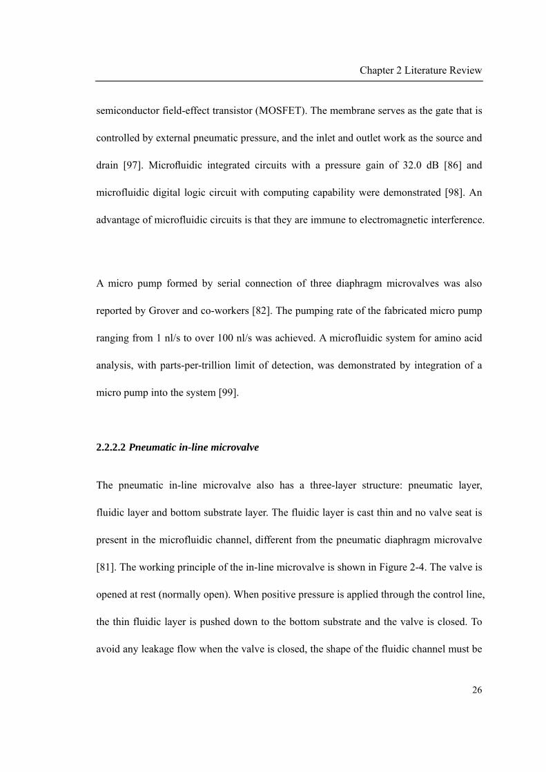
2.2.2.2 Pneumatic in-line microvalve
The pneumatic in-line microvalve also has a three-layer structure: pneumatic layer,
fluidic layer and bottom substrate layer. The fluidic layer is cast thin and no valve seat is
present in the microfluidic channel, different from the pneumatic diaphragm microvalve
[81]. The working principle of the in-line microvalve is shown in Figure 2-4. The valve is
opened at rest (normally open). When positive pressure is applied through the control line,
the thin fluidic layer is pushed down to the bottom substrate and the valve is closed. To
avoid any leakage flow when the valve is closed, the shape of the fluidic channel must be

Chapter 2 Literature Review
27
round instead of rectangular. Otherwise, the valve cannot be fully closed near the side
walls of the rectangular fluidic channel. PDMS is still the commonly used material for
fabricating such microvalves.
Figure 2-4 Schematic illustrating the working principle of pneumatically actuated inline
microvalve. (a) Microvalve is open at rest. (b) Microvalve is closed when positive
pressure is applied through the pneumatic channel. The thin fluidic layer is pushed down
to close the valve.
Large-scale integration of pneumatic in-line microvalves have been successfully
demonstrated by Quake’s group [100]. An application of this large-scale integration is in
PCR [101]. In this work, totally 2860 microvalves were integrated on a microfluidic chip.
400 PCR reactions were carried out simultaneously within isolated 3 nl compartments

Chapter 2 Literature Review
28
formed by the microvalves. The work presented is pretty useful in biochemical
experiments in which precious reagents are involved.
Marcus and co-workers reported a microdevice for single cell mRNA isolation and
analysis [8]. This system integrated the function of cell isolation, cell lysis, mRNA
purification, cDNA synthesis and cDNA purification. The device was scaled up to
process 50 different samples (50-plex) in parallel.
2.3 Oligonucleotide synthesis in a microfluidic device
Applying microfluidic technologies in oligonucleotide synthesis has been reported by
only a few researchers. In some studies, the microfluidic device offered micro reactors for
highly parallel synthesis [52, 102-104]. In other studies, a complete microfluidic
synthesizer was fabricated [105, 106].
2.3.1 Microfluidic device reactor
Oligonucleotide synthesis has been carried out in a microfluidic reactor. Hua and co-
workers developed a chemical-resistant microvalve array by coating parylene on PDMS
[102]. The microdevice was connected to a commercial oligonucleotide synthesizer and
the microvalve array was used to distribute the oligonucleotide synthesis reagents to

Chapter 2 Literature Review
29
different reaction channels for synthesizing oligonucleotide probes. However, no
characterization of the synthesized oligonucleotide was presented in this work.
Zhou and co-workers designed a microfluidic device with around 3600 reaction chambers
of picoliter volume [52, 103]. Oligonucleotides with different sequence were synthesized
in individual chambers by the PGA approach. The synthesized oligonucleotide was
successfully used for distinguishing single-base mismatch hybridization and assembly of
gene fragment with 712 and 714 bp in length.
Moorcroft and co-workers used PDMS as the solid support and directly synthesized an
oligonucleotide within the PDMS microchannel [104]. Although PDMS has the weakness
of incompatibility with certain organic solvents, this work proved that with substitution of
certain organic solvents used in oligonucleotide synthesis, PDMS can still be used as a
substrate material for oligonucleotide synthesis and potentially for fabricating DNA
microarray.
2.3.2 Microfluidic oligonucleotide synthesizer
Oligonucleotide synthesis in microfluidic reactors was usually done by connecting a
microfluidic device directly to a commercial oligonucleotide synthesizer. Therefore, there
is no fluidic control within the microfluidic device. The first real microfluidic
Chapter 2 Literature Review
30
oligonucleotide synthesizer was reported by Huang and co-workers [105]. In this work,
in-line microvalves were fabricated in PFPE solvent-resistant polymer to control the flow
of synthesis reagents. A 20-mer oligonucleotide was obtained in the device and its length
was confirmed by gel electrophoresis.
Extended research was conducted later by Lee and co-workers to simultaneously
synthesize 16 different oligonucleotides in the microfluidic synthesizer [106]. The
synthesized oligonucleotides were used for assembly of a gene fragment from Bacillus
cereus of 230 bp in length without further purification. The reported microfluidic
oligonucleotides synthesizer is a great progress in the development of oligonucleotide
synthesis instruments.

31
CHAPTER 3
ZERO DEAD-VOLUME MICROVALVE

Chapter 3 Zero Dead-volume Microvalve
32
3.1 Introduction
Microvalves integrated microfluidic devices have been used in applications where
sequential switching of a number of reagents is needed [105, 107, 108]. In some
applications, it is desirable to minimize intermixing and cross contamination among
reagents as the result can be badly affected by the purity of the reagents. In traditional
designs of microfluidic device with multiple inlets and integrated microvalves, all inlets
are distributed along the main channel or merge into the main channel at the beginning
(Figure 3-1). Connecting channels are usually placed in between the microvalves and the
main channel. During operation, small volumes of reagents can be trapped within the
connecting channels and lead to contamination of the reagent flow in the mainstream
channel. For many applications this contamination problem is negligible. However, for
some applications such as DNA synthesis, PCR and other analytical applications [109,
110], it is absolutely necessary to minimize intermixing and cross contamination among
reagents.

Chapter 3 Zero Dead-volume Microvalve
33
Figure 3-1 Traditional design of multiple valves integrated microfluidics (a) All inlets are
distributed along the main channel. (b) All inlets merge into the main channel at one point.
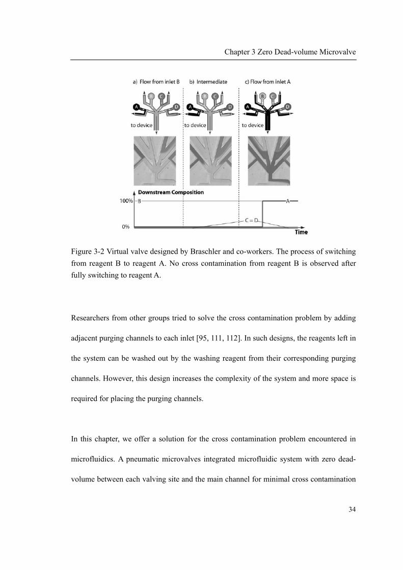
A few studies have been conducted to solve the cross contamination problem [95, 111,
112]. Braschler and co-workers have designed a virtual valve by incorporating a bypass
channel to each inlet channel side by side [111] (as shown in Figure 3-2). When a reagent
is selected (by increasing the corresponding inlet pressure), it flows towards the main
channel. At the same time, the higher inlet pressure causes reagents from other inlets to
be diverted to its bypass channel. In other words, the selected reagent washes all the other
reagents out into their respective bypass channels. Therefore, cross contamination is
avoided. However, due to the presence of bypass channels and absence of real valves,
reagents keep flowing and are wasted all the time, which is not cost effective.
(a) (b)
Chapter 3 Zero Dead-volume Microvalve
34
Figure 3-2 Virtual valve designed by Braschler and co-workers. The process of switching
from reagent B to reagent A. No cross contamination from reagent B is observed after
fully switching to reagent A.
Researchers from other groups tried to solve the cross contamination problem by adding
adjacent purging channels to each inlet [95, 111, 112]. In such designs, the reagents left in
the system can be washed out by the washing reagent from their corresponding purging
channels. However, this design increases the complexity of the system and more space is
required for placing the purging channels.
In this chapter, we offer a solution for the cross contamination problem encountered in
microfluidics. A pneumatic microvalves integrated microfluidic system with zero dead-
volume between each valving site and the main channel for minimal cross contamination
Chapter 3 Zero Dead-volume Microvalve
35
of reagents is demonstrated. The main channel is zigzag shaped and the microvalves sit
exactly at each turning point of the main channel, hence creating a zero dead-volume
between each valving site and the main channel. This zero dead-volume allows any
reagent entering the main channel to be thoroughly washed out after use and not to
remain entrapped within the microfluidic device. Therefore contamination of the reagent
used in the current step to subsequently added reagents in the next step is minimized. To
prove the zero dead-volume characteristic, PCR is used to detect trace amount of DNA
template molecules left in the device after washing.
3.2 Microvalves design and fabrication
3.2.1 Zero dead-volume microvalve design
The design of the zero dead-volume is shown in Figure 3-3. (NB: The term “zero dead-
volume” in this work refers to the volume between each valving site and the main
channel is zero and hence no reagents can be trapped. However, there is always leftover
reagent in the main channel and washing is always needed to remove these reagents from
the main channel.) All microvalves are positioned at the turning points of a zigzag shaped
main channel; except the outermost left valve which is used to control the main channel
flow itself. The novel characteristic of the design is that the connecting channel between
the main channel and each valve site, which was commonly used in previous studies [105,
107, 108], is removed in this design. The distance between each valve site and the main

Chapter 3 Zero Dead-volume Microvalve
36
channel is visibly reduced to zero, hence creating a zero dead-volume between each valve
site and the main channel. This zero dead-volume allows any reagent entering the main
channel to be thoroughly washed out after use and not to remain entrapped within the
microfluidic device. The zero dead-volume can effectively minimize cross contamination
among reagents as no previous reagents can be trapped in the device. All branch channels
are aligned with their downstream direction of the main channel to aid reagents to flow
towards the outlet. In our design a total number of 9 valves are integrated; however, more
valves could be integrated if necessary.
Figure 3-3 Design of the microvalves integrated microfluidic device with zero dead-
Chapter 3 Zero Dead-volume Microvalve
37
volume characteristic. The main channel is zigzag shaped. The microvalves are
positioned at each turning point of the main channel.
3.2.2 Microvalve working principles
The working principle of the valve is shown in Figure 2-3. When positive pressure is
applied through the pneumatic port, the membrane is pressed against the valve seat and
the valve is closed. Liquid flow stops behind the valve seat (Figure 2-3(a)). On the other
hand, when negative pressure is applied, the thin flexible membrane is lifted away from
the valve seat and a connecting channel is formed between the valve seat and the
membrane. The valve is opened and the liquid can flow over the valve seat (Figure
2-3(b)).
3.2.3 Microvalve fabrication
3.2.3.1 Master fabrication and PDMS micromolding
The microvalves integrated microfluidic chip was fully fabricated in PDMS (Sylgard 184
Silicone Elastomer kit, Dow Corning, US). The chip has a fluidic-membrane-pneumatic
three-layer structure. The fluidic layer and pneumatic layer were both fabricated by
PDMS micromolding and the membrane was made by spin-coating PDMS on silicon
wafer.
Chapter 3 Zero Dead-volume Microvalve
38
The masters for PDMS micromolding were fabricated by photolithography. SU-8 2050
negative photoresist (Microchem, US) was applied on silicon wafers by spin-coating (~50
µm thickness), followed by a two-step soft bake at 65 C for 3 minutes and 95 C for 6
minutes. The resist coated wafer was then exposed to UV light at 365 nm through a
transparency film mask, followed by a post exposure bake at 65 C for 1 minute and 95
C for 5 minutes. The exposed photoresist was finally developed in SU-8 developer for 6
minutes.
To micromold PDMS, the fabricated master was first exposed to 1H,1H,2H,2H-
perfluorooctyl-trichlorosilane (PFOTCS) vapor under vacuum at room temperature for 15
minutes. Fully mixed PDMS base and curing agent (10:1 ratio) was poured onto the
master and degassed under vacuum for 30 minutes. The PDMS was then baked at 65 C
in an oven for at least 2 hours. After baking, the PDMS microchip was peeled off from
the master, washed with isopropyl alcohol (IPA) and double distilled water (ddH2O),
blown dry with nitrogen and ready to use.
3.2.3.2 PDMS membrane fabrication
To fabricate the PDMS membrane, the PDMS was spin-coated on a silicon wafer. Firstly,
2 ml of fully mixed PDMS was directly poured on the center of a 4-inch PFOTCS coated
silicon wafer. Then the wafer was spun at 2000 rpm for 30 seconds and followed by

Chapter 3 Zero Dead-volume Microvalve
39
baking for 1 hour at 65 C on a hot plate. The PDMS membrane was then washed with
IPA, ddH2O, blown dry with nitrogen and ready to use. The fabrication process of the
PDMS membrane should be completed in a clean room environment as dust can affect
the functionality of the fabricated PDMS membrane.
The thickness of the fabricated PDMS membrane was measured by using a microscope
(Olympus BX41). A strip of the membrane was cut out and removed from the silicon
wafer. The cutting edge of the membrane that still stuck on the wafer was observed under
the microscope. First, the top surface of the membrane was focused and the reading of the
micrometer on the fine focus knob was taken. After that, the surface of the silicon wafer
was focused by adjusting the fine focus knob and the reading was taken again. By
calculating the difference of the two readings, the thickness of the PDMS membrane was
obtained.
Figure 3-4 shows the relationship between the thickness of the fabricated PDMS
membrane and the spinning speed. As the spinning speed increases, the thickness of the
PDMS membrane decreases. It is also worth to note that as the spinning speed increases,
the rate of thickness decreasing becomes smaller. An empirical equation for the
relationship between polymer thickness (t) and spinning speed ( ), solution
concentration (C) and molecular weight (η) was given before:
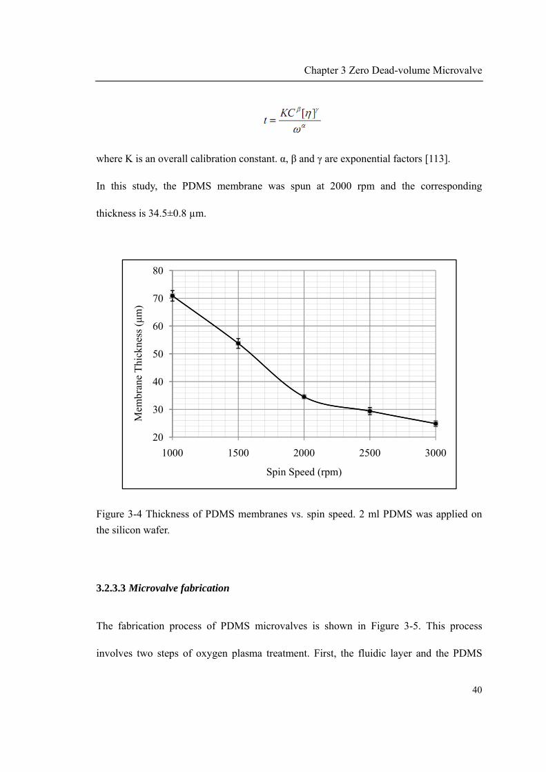
Chapter 3 Zero Dead-volume Microvalve
40
where K is an overall calibration constant. α, β and γ are exponential factors [113].
In this study, the PDMS membrane was spun at 2000 rpm and the corresponding
thickness is 34.5±0.8 µm.
Figure 3-4 Thickness of PDMS membranes vs. spin speed. 2 ml PDMS was applied on
the silicon wafer.
3.2.3.3 Microvalve fabrication
The fabrication process of PDMS microvalves is shown in Figure 3-5. This process
involves two steps of oxygen plasma treatment. First, the fluidic layer and the PDMS
20
30
40
50
60
70
80
1000 1500 2000 2500 3000
Mem
bran
e T
hick
ness
(μm
)
Spin Speed (rpm)
Chapter 3 Zero Dead-volume Microvalve
41
membrane were treated by oxygen plasma (March Instrument Incorporated, radio
frequency generator power 200 W, plasma treatment period 30 s, oxygen pressure 450
mTorr) and then bonded together for 2 hours at 65 ºC. After baking, the PDMS fluidic
layer and the thin PDMS membrane were bonded permanently. As the PDMS membrane
was the moving part of the microvalve, it should not bond with the fluidic layer at the
valve seat regions. Therefore, during oxygen plasma treatment, the valve seat regions on
the fluidic layer must be covered from exposure to plasma. The valve seat was covered
by using an oil-based permanent marker pen (Zebra, Japan) to directly mark on the target
areas. Only oil-based marker pen instead of water-based one can be used here. This is
because PDMS is very hydrophobic [114], as a consequence, water-based mark does not
stick to the raw PDMS surface well and droplets can be easily formed.
The bonded two-layer PDMS assembly was then peeled off from the flat silicon wafer.
Next, the PDMS pneumatic layer and the other surface of the thin PDMS membrane were
bonded together by treating with oxygen plasma again. Alignment of the valve seats with
the pneumatic controlling channels was done under a stereo microscope. Finally the
three-layer PDMS sandwich was baked at 65 ºC overnight. To remove the valve seat
protective marking, IPA was used to flush through the microvalves following by washing
with ddH2O. After drying in the oven, the microchip was ready to use.
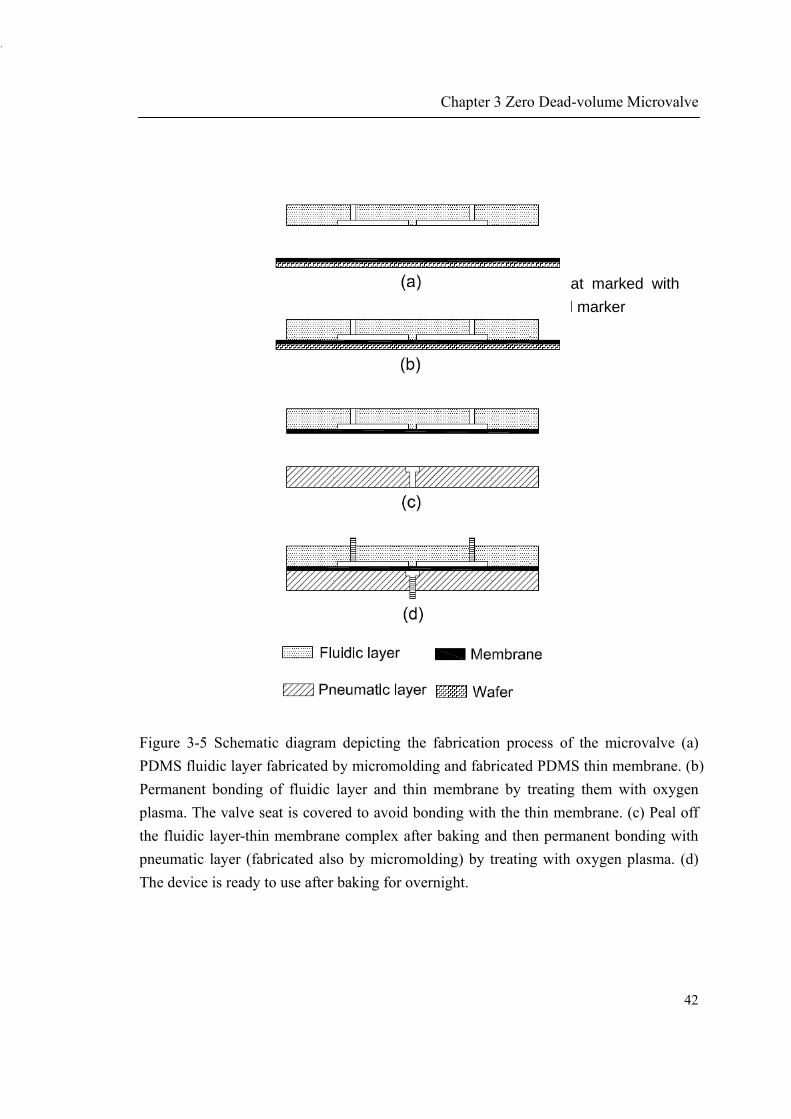
Chapter 3 Zero Dead-volume Microvalve
42
Figure 3-5 Schematic diagram depicting the fabrication process of the microvalve (a)
PDMS fluidic layer fabricated by micromolding and fabricated PDMS thin membrane. (b)
Permanent bonding of fluidic layer and thin membrane by treating them with oxygen
plasma. The valve seat is covered to avoid bonding with the thin membrane. (c) Peal off
the fluidic layer-thin membrane complex after baking and then permanent bonding with
pneumatic layer (fabricated also by micromolding) by treating with oxygen plasma. (d)
The device is ready to use after baking for overnight.
valve seat marked with
oil-based marker

The fabrica
fluidic chan
however, th
Figure 3-6
3.3 Result
3.3.1 Micro
3.3.1.1 Mic
Figure 3-7
conditions.
ated microv
nnel was fi
he size of th
Fabricated m
and discus
ovalve char
crovalve ope
shows tw
When a po
M
valves integ
lled with g
he whole chi
microvalve
ssion
racterizatio
eration
wo working
ositive press
Microvalve
grated micr
green color
ip can be fu
s integrated
on
states of
sure (7 psi)
Inlets
s
Chapter
rofluidic ch
liquid. The
urther reduc
d microfluid
the fabrica
) was applie
r 3 Zero De
hip is show
e whole chip
ced accordin
dic chip
ated microv
ed through
Pneumatic
ad-volume
wn in Figur
p is 7 cm i
ng to require
valves unde
the pneuma
c Ports
Microvalve
43
re 3-6. The
in diameter;
ement.
er different
atic channel
e
3
e
;
t
l
Chapter 3 Zero Dead-volume Microvalve
44
to the thin membrane, the membrane temporarily sealed with the valve seat and the valve
was closed (Figure 3-7(a)). Under normal conditions, i.e. without external pressure, the
design of the valve structure would allow the microvalve to remain closed. This occurs as
both the valve seat and the membrane are fabricated in PDMS and the reversible sealing
of PDMS to PDMS closes the valve. However, due to the weak bonding of PDMS-PDMS
reversible sealing, the temporary sealing can be broken by pressure of magnitude larger
than 1 psi. Therefore, an external positive pressure is intentionally used to ensure that the
valve is closed. In this microvalve design, dust or large particles cannot be tolerated. This
is because that these contaminants could be stuck in between the membrane and the valve
seat, causing the valve not to be fully closed. For this reason, in-line filters were placed in
between the reagent reservoirs and the microchip inlets in this study to avoid malfunction
of the microvalves.
On the other hand, when a negative pressure (-4.2 psi) was applied, this negative pressure
applied would overcome the reversible bonding and separate the membrane and the valve
seat. The flexible membrane would be sucked towards the pneumatic channel and a
connecting channel between the membrane and the valve seat was formed. This formed
channel provides a fluidic path for liquid to enter the main channel (Figure 3-7(b)). After
the valve is opened, in theory, less negative pressure is needed to maintain the open state
of the valve. The time needed to open the valve is estimated to be less than 17 ms (liquid
can pass through the valve when the controlling solenoid valve is energized for 25 ms to

Chapter 3 Zero Dead-volume Microvalve
45
allow vacuum to be applied on the membrane. However, the solenoid valve needs 8 ms to
be energized).
(a)
(b)
Figure 3-7 Photograph of the microvalve. (a) The microvalve is closed by external
positive pressure through pneumatic channel. (b) The microvalve is opened by external
negative pressure through pneumatic channel.
500 µm
Pneumatic channel
Valve seat
Main channel

Chapter 3 Zero Dead-volume Microvalve
46
3.3.1.2 Leakage pressure
The leakage pressure of the fabricated microvalve is defined as the maximum liquid
driven pressure the valve can retain without leakage at certain valve closing pressure.
Figure 3-8 shows the relationship between the valve closing pressure and the leakage
pressure. As expected, the microvalve can retain higher liquid driven pressure as the
valve closing pressure increases.
From Figure 3-8, we can see that when the valve closing pressure is 0, the valve can still
retain a pressure of ~1 psi. This is due to the weak reversible sealing of PDMS to PDMS.
It was reported previously that the reversible PDMS-PDMS bonding can retain as much
as 5 psi pressure [115]. In that study, both PDMS layers were thick. Therefore, the
elasticity is negligible. However, in our case, the pressure that can be retained is much
lower because the thin PDMS membrane is very flexible; as a consequence, a weaker
pressure is able to bend it and causing separation of the membrane and the valve seat.
The valve closing pressure used in this study is 7 psi. At this pressure, the leakage
pressure is as high as 9.8 psi. However, the liquid driving pressure used in this study is
only 2 psi. Therefore, under normal conditions, it can be guaranteed that there is no
leakage of reagents through the microvalve.
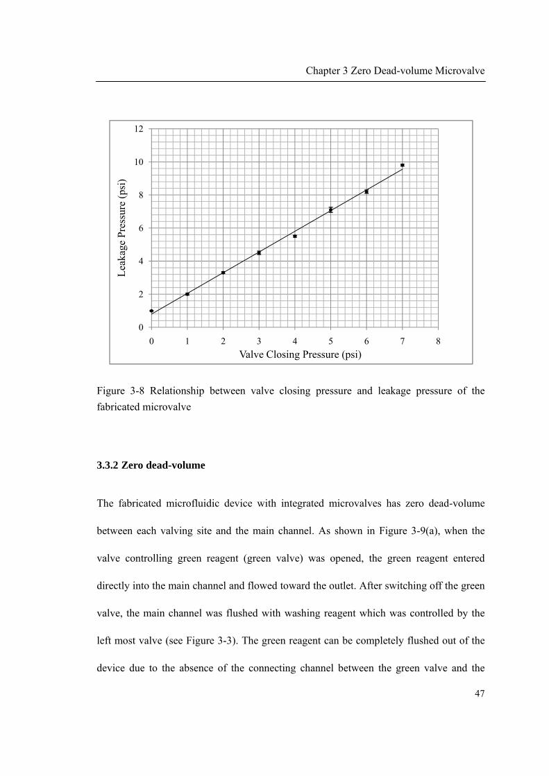
Chapter 3 Zero Dead-volume Microvalve
47
Figure 3-8 Relationship between valve closing pressure and leakage pressure of the
fabricated microvalve
3.3.2 Zero dead-volume
The fabricated microfluidic device with integrated microvalves has zero dead-volume
between each valving site and the main channel. As shown in Figure 3-9(a), when the
valve controlling green reagent (green valve) was opened, the green reagent entered
directly into the main channel and flowed toward the outlet. After switching off the green
valve, the main channel was flushed with washing reagent which was controlled by the
left most valve (see Figure 3-3). The green reagent can be completely flushed out of the
device due to the absence of the connecting channel between the green valve and the
0
2
4
6
8
10
12
0 1 2 3 4 5 6 7 8
Lea
kage
Pre
ssur
e (p
si)
Valve Closing Pressure (psi)

Chapter 3 Zero Dead-volume Microvalve
48
main channel, which is different from previous designs [105, 107, 108]. The complete
removal of green liquid minimized the possibility of its contamination to following
reagents entering the main channel. It can be seen in Figure 3-9(b) that the red reagent,
which was controlled by an upstream valve, flowed through the main channel without
mixing with green reagent after the green valve was closed.
In the design of the microfluidic device, the main channel is zigzag shaped and
microvalves sit exactly at each turning point of the main channel. The distance between
each valving site and the main channel was visibly reduced to zero, hence creating a zero
dead-volume between each valving site and the main channel. This zero dead-volume
allowed any reagent entering the main channel to be thoroughly washed out after use and
not to remain entrapped within the microfluidic device.

Chapter 3 Zero Dead-volume Microvalve
49
(a)
(b)
Figure 3-9 Photograph of the microvalve showing the zero dead-volume characteristic;
two colored liquids (green and red) are used for illustration. (a) The microvalve that
controls green liquid was opened. (b) The microvalve that controls green liquid was
closed and another microvalve (located at upstream of the main channel) that controls red
liquid was opened. No contamination of the red liquid from the green liquid was observed.
3.3.3 Minimal cross contamination tested by PCR
PCR was used as a detection tool to demonstrate minimal cross contamination of the zero

Chapter 3 Zero Dead-volume Microvalve
50
dead-volume microvalve as PCR is a very sensitive assay for detection of specific DNA
templates. With appropriate primer design and optimized amplifying conditions, as few as
10 DNA template molecules can be detected (Figure 3-10).
PCR template (plasmid DNA, 4142 bp, Promega) with a concentration of 1×10⁶
molecules/µL in 1X TE buffer was controlled and fed into the main channel by one of
these microvalves. The microvalve was opened for 5 seconds followed by TE buffer
washing for either 10, 20 or 30 seconds. TE buffer was controlled by the left most
microvalve. After washing for desired time, another 20 µL of the washing buffer was
injected into the device and the effluent was collected at the outlet. The total volume of
the PDMS main channel is 1.8 µL and flow rate is 5 µL/s.
This effluent containing the DNA template molecules was mixed with other PCR
components (PCR core system II, Promega, US) including nucleotide mix, polymerase,
primers, buffers and water to a final volume of 50 µL and a concentration described
previously [116]. 35 PCR amplification cycles were completed in PCR thermal cycler
(PTC-200, MJ Research) and the product (323 bp) was analyzed by 1.5% agarose gel
electrophoresis. The gel electrophoresis was run at 120 V for 45 minutes and stained with
SYBR® Safe dye. (Invitrogen, US). The gel was imaged with G:BOX gel documentation
system (Synoptics, UK).
As shown in Figure 3-10(a), after washing with TE buffer for 10 seconds (Lane 6), the

Chapter 3 Zero Dead-volume Microvalve
51
effluent produced a band intensity which was stronger than that of PCR product amplified
from 1000 template molecules (Lane 2), indicating that the amount of template molecules
was more than 1000 in the 20 µL effluent after 10 seconds of washing. However, after 30
seconds of washing (Lane 8), the effluent produced a band intensity which was between
the intensity of PCR product amplified from 100 (Lane 3) and 10 (Lane 4) template
molecules; equating to 0.5 to 5 template molecules per µL. By comparing with the
original concentration of the PCR template stock solution (1×10⁶ molecules/µL), there
was a 10-6 reduction factor in the concentration. Extended washing can further reduce the
concentration of the template molecules in the effluent.
For comparison, the same experiment was conducted by microvalve system of traditional
design as shown in Figure 3-1(a). The PCR and gel electrophoresis image is shown in
Figure 3-10(b). It can be seen that after washing for 30 seconds, the 20 µL effluent still
contained more than 1000 DNA template molecules, which indicates that the washing
was not as efficient as in our design. This could lead to cross contamination of reagents
that cannot be tolerated in certain applications.
In summary, it has been demonstrated that cross contamination of reagents in our
microdevice design can be minimized to part in a million (ppm) levels after washing for
30 seconds.

Figure 3-1
electrophor
from 1000,
for 10 s, 20
0 Trace am
resis. Lane 1
100, 10 an
0 s and 30 s.
mount of D
1: 100 bp D
nd 0 templat
. (a) Our mi
(a
(b
DNA temp
DNA ladder;
te molecule
icrovalve de
Chapter
a)
b)
plate molec
; Lane 2-5: p
s; Lane 6-8
esign (b) Tr
r 3 Zero De
cules detect
positive con
8: PCR with
aditional m
ad-volume
tion by PC
ntrol with P
h effluent af
microvalve d
Microvalve
52
CR and gel
PCR starting
fter washing
design
e
2
l
g
g

Chapter 3 Zero Dead-volume Microvalve
53
3.4 Conclusion
In this chapter, we designed and fabricated a microvalves integrated microfluidic device
for minimal cross contamination among the reagents. The zigzag shape of the main
microfluidic channel and the position of each microvalve removed the dead-volume
between the common pathway and each valving site, which effectively minimized the
contamination of currently used reagent to subsequently added reagents. The microfluidic
device presented in this chapter is a good candidate to be used in chemical synthesis and
biological studies where reagents need to be added into a reaction chamber in a serial
manner and cross contamination among reagents is an important issue and must be
avoided.

54
CHAPTER 4
OLIGONUCLEOTIDE SYNTHESIS
IN A PORTABLE SYNTHESIZER

Chapter 4 Oligonucleotide Synthesis in a Portable Synthesizer
55
4.1 Introduction
DNA oligonucleotides are one of the most common materials used in biomolecular
research and applications nowadays. Every year, hundreds of thousands of
oligonucleotides are synthesized. Through the development of the phosphoramidite solid
phase synthesis of oligonucleotide, the process has been fully automated and can be
completed in oligonucleotide synthesizers. The oligonucleotide synthesizer has been
commercialized for many years and there are several companies offering this product.
However, due to the complexity of the synthesis chemistry in which a number of
synthesis reagents are involved, those synthesizers are bulky in size. The limitation on the
size of the commercialized oligonucleotide synthesizers makes them only suitable to be
used in laboratory and excludes their potential in the field applications.
Nowadays, due to the continuous threat from terrorism, in the field monitoring and
detection of biological warfare and infectious disease agents such as bacteria and viruses
become absolutely necessary. State of the art DNA based bioassays for the detection of
these biological substances make use of oligonucleotides that function as either probes
for hybridization or primers for PCR [117]. However, due to the lack of portability of
existing commercialized oligonucleotide synthesizing instruments, pre-made
oligonucleotides with known sequences need to be prepared and then brought to the
places where bioassays are carried out. As a consequence, it is impossible to conduct
bioassay with oligonucleotides of completely new sequences. In such case, no immediate

Chapter 4 Oligonucleotide Synthesis in a Portable Synthesizer
56
in the field detection of artificially manipulated or naturally mutated agents harmful to
human is possible. Therefore, there is an emerging need for new instrument that can
complement the state of the art DNA bioassay technologies by immediately synthesizing
oligonucleotides as either primers or probes with any sequence on demand in the field.
Microfluidic is a promising technology due to its small size and ease of integration. The
invention of microfluidic valves enables microfluidic devices to manipulate and control
fluids flow and therefore dramatically extended their use [81, 85]. Oligonucleotide
synthesis is an application where sequential switching of a number of reagents is needed.
Therefore, microfluidic technology is a potential solution for building a portable
oligonucleotide synthesizer. As far as we know, a few studies have been conducted on
developing microfluidic device for oligonucleotide synthesis [105, 106]. However, no
work has been done aiming to develop an oligonucleotide synthesizer in a portable format
that can be potentially used for in the field applications.
In this chapter, a microfluidics based portable oligonucleotide synthesizer is proposed and
built. The zero dead-volume microvalves integrated microfluidic chip (designed and
reported in pervious chapter) is the core component of the portable synthesizer. By the aid
of other peripheral components (including electronic & electrical, fluidic, and pneumatic
part), the portable oligonucleotide synthesizer was successfully used to synthesize both
oligonucleotide primers and probes. The sequence and biological functionality of the
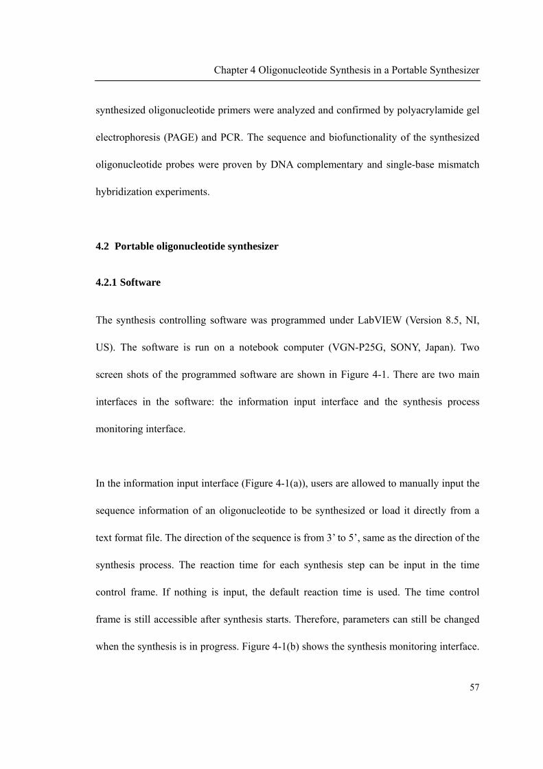
Chapter 4 Oligonucleotide Synthesis in a Portable Synthesizer
57
synthesized oligonucleotide primers were analyzed and confirmed by polyacrylamide gel
electrophoresis (PAGE) and PCR. The sequence and biofunctionality of the synthesized
oligonucleotide probes were proven by DNA complementary and single-base mismatch
hybridization experiments.
4.2 Portable oligonucleotide synthesizer
4.2.1 Software
The synthesis controlling software was programmed under LabVIEW (Version 8.5, NI,
US). The software is run on a notebook computer (VGN-P25G, SONY, Japan). Two
screen shots of the programmed software are shown in Figure 4-1. There are two main
interfaces in the software: the information input interface and the synthesis process
monitoring interface.
In the information input interface (Figure 4-1(a)), users are allowed to manually input the
sequence information of an oligonucleotide to be synthesized or load it directly from a
text format file. The direction of the sequence is from 3’ to 5’, same as the direction of the
synthesis process. The reaction time for each synthesis step can be input in the time
control frame. If nothing is input, the default reaction time is used. The time control
frame is still accessible after synthesis starts. Therefore, parameters can still be changed
when the synthesis is in progress. Figure 4-1(b) shows the synthesis monitoring interface.

Chapter 4 Oligonucleotide Synthesis in a Portable Synthesizer
58
The information about the overall synthesis progress and the current reaction in each
synthesis cycle can both be observed.
(a)
(b)
Figure 4-1 Screen shots of the software for controlling oligonucleotide synthesis. The
software was programmed under LabVIEW. (a) The information input interface (b) The
synthesis monitoring interface.
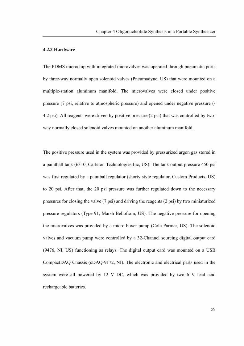
Chapter 4 Oligonucleotide Synthesis in a Portable Synthesizer
59
4.2.2 Hardware
The PDMS microchip with integrated microvalves was operated through pneumatic ports
by three-way normally open solenoid valves (Pneumadyne, US) that were mounted on a
multiple-station aluminum manifold. The microvalves were closed under positive
pressure (7 psi, relative to atmospheric pressure) and opened under negative pressure (-
4.2 psi). All reagents were driven by positive pressure (2 psi) that was controlled by two-
way normally closed solenoid valves mounted on another aluminum manifold.
The positive pressure used in the system was provided by pressurized argon gas stored in
a paintball tank (6310, Carleton Technologies Inc, US). The tank output pressure 450 psi
was first regulated by a paintball regulator (shorty style regulator, Custom Products, US)
to 20 psi. After that, the 20 psi pressure was further regulated down to the necessary
pressures for closing the valve (7 psi) and driving the reagents (2 psi) by two miniaturized
pressure regulators (Type 91, Marsh Bellofram, US). The negative pressure for opening
the microvalves was provided by a micro-boxer pump (Cole-Parmer, US). The solenoid
valves and vacuum pump were controlled by a 32-Channel sourcing digital output card
(9476, NI, US) functioning as relays. The digital output card was mounted on a USB
CompactDAQ Chassis (cDAQ-9172, NI). The electronic and electrical parts used in the
system were all powered by 12 V DC, which was provided by two 6 V lead acid
rechargeable batteries.

Chapter 4 Oligonucleotide Synthesis in a Portable Synthesizer
60
4.2.3 System integration
The complete portable oligonucleotide synthesizer comprises three main parts: the
electrical and electronic controlling part, the pneumatic controlling part, and the fluidic
part. Figure 4-2(a) shows the schematic diagram of the portable oligonucleotide synthesis
system. The three main parts are marked with different colors. Figure 4-2(b) shows the
photograph of the portable oligonucleotide synthesizer.
All parts forming the portable synthesizer were mounted on a home-made aluminum rack.
The rack was divided into two main compartments. The left compartment was for
pneumatic parts and electrical and electronic parts. The right compartment was for liquid
reagents related parts including the microfluidic device and reagent reservoirs and waste
bottle. The size of the aluminum rack is 42 cm × 19 cm × 28 cm and the weight is around
6 kg. The whole rack can be inserted into an aluminum suitcase for carrying purpose. The
portability of the whole system makes it easy to carry and suitable for being used in the
field. A detailed list of all components used to build the portable oligonucleotide
synthesizer can be seen in Appendix A.
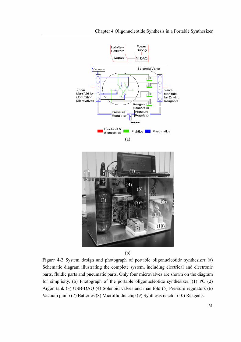
Chapter 4 Oligonucleotide Synthesis in a Portable Synthesizer
61
(a)
(b)
Figure 4-2 System design and photograph of portable oligonucleotide synthesizer (a)
Schematic diagram illustrating the complete system, including electrical and electronic
parts, fluidic parts and pneumatic parts. Only four microvalves are shown on the diagram
for simplicity. (b) Photograph of the portable oligonucleotide synthesizer: (1) PC (2)
Argon tank (3) USB-DAQ (4) Solenoid valves and manifold (5) Pressure regulators (6)
Vacuum pump (7) Batteries (8) Microfluidic chip (9) Synthesis reactor (10) Reagents.
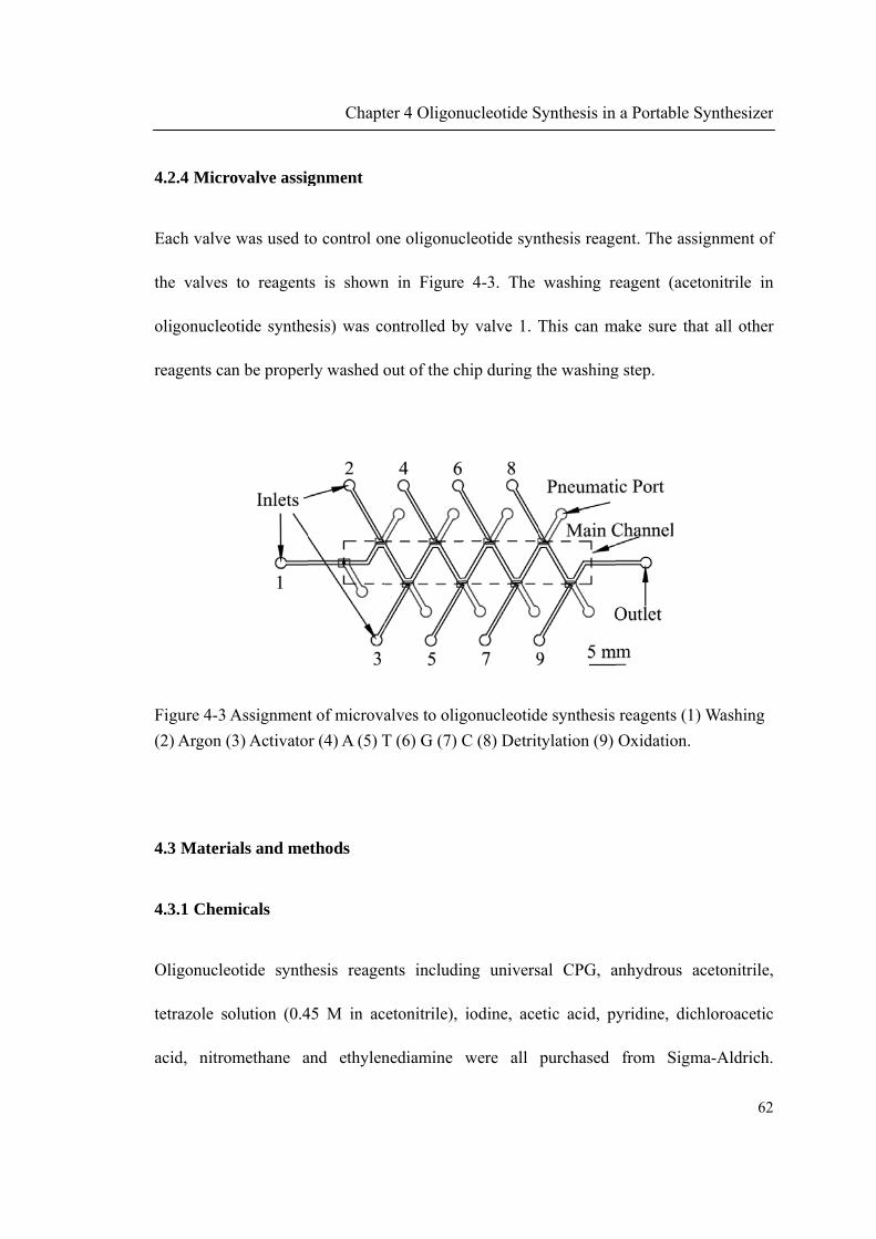
4.2.4 Micro
Each valve
the valves
oligonucleo
reagents ca
Figure 4-3 A
(2) Argon (
4.3 Materi
4.3.1 Chem
Oligonucle
tetrazole so
acid, nitro
ovalve assig
was used t
to reagent
otide synthe
an be proper
Assignment
3) Activato
als and me
micals
otide synth
olution (0.4
omethane a
Chapt
gnment
to control on
ts is shown
esis) was co
rly washed o
t of microva
r (4) A (5) T
ethods
hesis reage
45 M in ac
and ethylen
ter 4 Oligon
ne oligonuc
n in Figure
ontrolled by
out of the ch
alves to olig
T (6) G (7) C
nts includi
etonitrile),
nediamine
nucleotide S
cleotide syn
e 4-3. The
y valve 1. T
hip during t
gonucleotid
C (8) Detrit
ing univers
iodine, ace
were all
Synthesis in
nthesis reage
washing re
This can m
the washing
de synthesis
tylation (9)
sal CPG, a
etic acid, py
purchased
a Portable
ent. The ass
eagent (ace
make sure th
g step.
reagents (1
Oxidation.
anhydrous a
yridine, dic
from Sigm
Synthesizer
62
signment of
etonitrile in
hat all other
) Washing
acetonitrile
chloroacetic
ma-Aldrich
r
2
f
n
r
,
c
.

Chapter 4 Oligonucleotide Synthesis in a Portable Synthesizer
63
Phosphoramidites including 5'-dimethoxytrityl-N-benzoyl-2'-deoxyadenosine,3'-[(2-
cyanoethyl)- (N,N-diisopropyl)]-phosphoramidite (dA), 5'-Dimethoxytrityl-N-benzoyl-2'-
deoxycytidine,3'-[(2-cyanoethyl)- (N,N-diisopropyl)]-phosphoramidite (dC), 5'-
Dimethoxytrityl-N-isobutyryl-2'-deoxyguanosine,3'-[(2-cyanoethyl)- (N,N-diisopropyl)]-
phosphoramidite (dG), and 5'-Dimethoxytrityl-2'-deoxythymidine,3'-[(2-cyanoethyl)-
(N,N-diisopropyl)]-phosphoramidite (dT), were purchased from Glen Research (US). All
reagents were directly used as received without further purification.
4.3.2 Synthesis reactor
4.3.2.1 Reactor for primer synthesis on CPG
Oligonucleotide primer was directly synthesized on CPG. The reactor for primer
synthesis is shown in Figure 4-4. A hole with 1 mm in diameter was punched through a
PDMS cube. A glass microfiber filter (Schleicher & Schuell, Germany) was inserted into
the punched hole. Two FEP tubings were then inserted into the hole from both ends. The
glass fiber filter was thus fixed in between the two tubings. To load CPG into the reactor,
they were first suspended in acetonitrile. Then the FEP tubing was connected to a syringe.
The CPG (around 1 mg) was sucked into the reactor and stayed above the glass filter,
while liquid can pass through the filter. The reactor was directly connected to the outlet of
the microfluidic chip and ready for synthesis.

Chapter 4 Oligonucleotide Synthesis in a Portable Synthesizer
64
Figure 4-4 Reactor for oligonucleotide primer synthesis. (1) PDMS cube (2) Glass fiber
filter (3)(4) FEP tubing (5) CPG.
4.3.2.2 Reactor for probe synthesis on glass slide
Oligonucleotide probe was synthesized on a surface modified microscope glass slide. The
synthesis reactor (Figure 4-5) was formed by reversibly sealing the glass slide with a
PDMS microfluidic channel. The microchannel (16 mm length × 500 m width × 50 m
height) with one inlet and one outlet was fabricated by micromolding as previously
described (Section 3.2.3.1). The formed reactor had a volume of 0.4 L. Oligonucleotide
probe was then synthesized on the glass slide surface within the formed channel. The
PDMS-glass sandwich was held firmly by an acrylic case to prevent leakage. The inlet of
the formed reactor was directly connected to the outlet of the microfluidic chip.

Chapter 4 Oligonucleotide Synthesis in a Portable Synthesizer
65
Figure 4-5 Reactor for oligonucleotide probe synthesis. (1) Top acrylic cover with tubing
access holes (2) PDMS microchannel (3) Surface modified microscope glass slide (4)
Bottom acrylic case.
4.3.3 Surface modification of microscope glass slides
Oligonucleotide was synthesized on microscope glass slides as probe for DNA
hybridization. The microscope glass slides were modified as previously reported [118].
They were first treated with 2% N-(3-triethoxysilylpropyl)-4-hydroxybutyramide in 95%
ethanol for 4 hours at room temperature. After that, the slides were thoroughly rinsed
with ethanol and then cured in vacuum oven at 120 °C for 1 hour. The treated slides were
stored in dehumidifying cabinet if not immediately used. The scheme of the surface
modification reaction is shown in Figure 4-6.
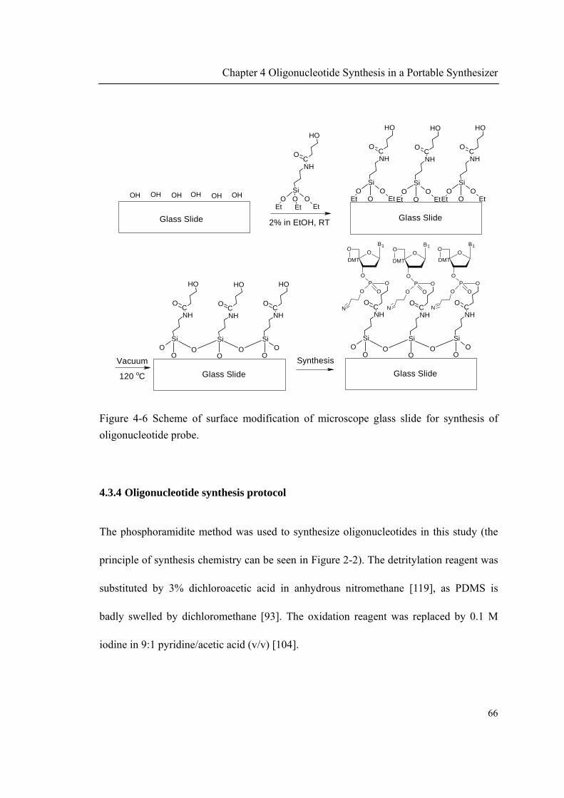
Chapter 4 Oligonucleotide Synthesis in a Portable Synthesizer
66
2% in EtOH, RTGlass Slide
OH OH OH OH OH OH
Synthesis
OH
CNH
OOOSi
Et Et Et
O
Glass Slide
OH
CNH
OO
OSi
Et Et
O
OH
CNH
OO
OSi
Et Et
O
OH
CNH
OO
OSi
Et Et
O
Glass Slide
OH
CNH
OO
OSi
O
OH
CNH
OO
Si
O
OH
CNH
OO
Si
O
Vacuum
120 oC Glass Slide
O
CNH
OO
OSi
O
O
CNH
OO
Si
O
O
CNH
OO
Si
O
DMT
O
P
OO
O
B1
O
N
DMT
O
P
OO
O
B1
O
N
DMT
O
P
OO
O
B1
O
N
Figure 4-6 Scheme of surface modification of microscope glass slide for synthesis of
oligonucleotide probe.
4.3.4 Oligonucleotide synthesis protocol
The phosphoramidite method was used to synthesize oligonucleotides in this study (the
principle of synthesis chemistry can be seen in Figure 2-2). The detritylation reagent was
substituted by 3% dichloroacetic acid in anhydrous nitromethane [119], as PDMS is
badly swelled by dichloromethane [93]. The oxidation reagent was replaced by 0.1 M
iodine in 9:1 pyridine/acetic acid (v/v) [104].
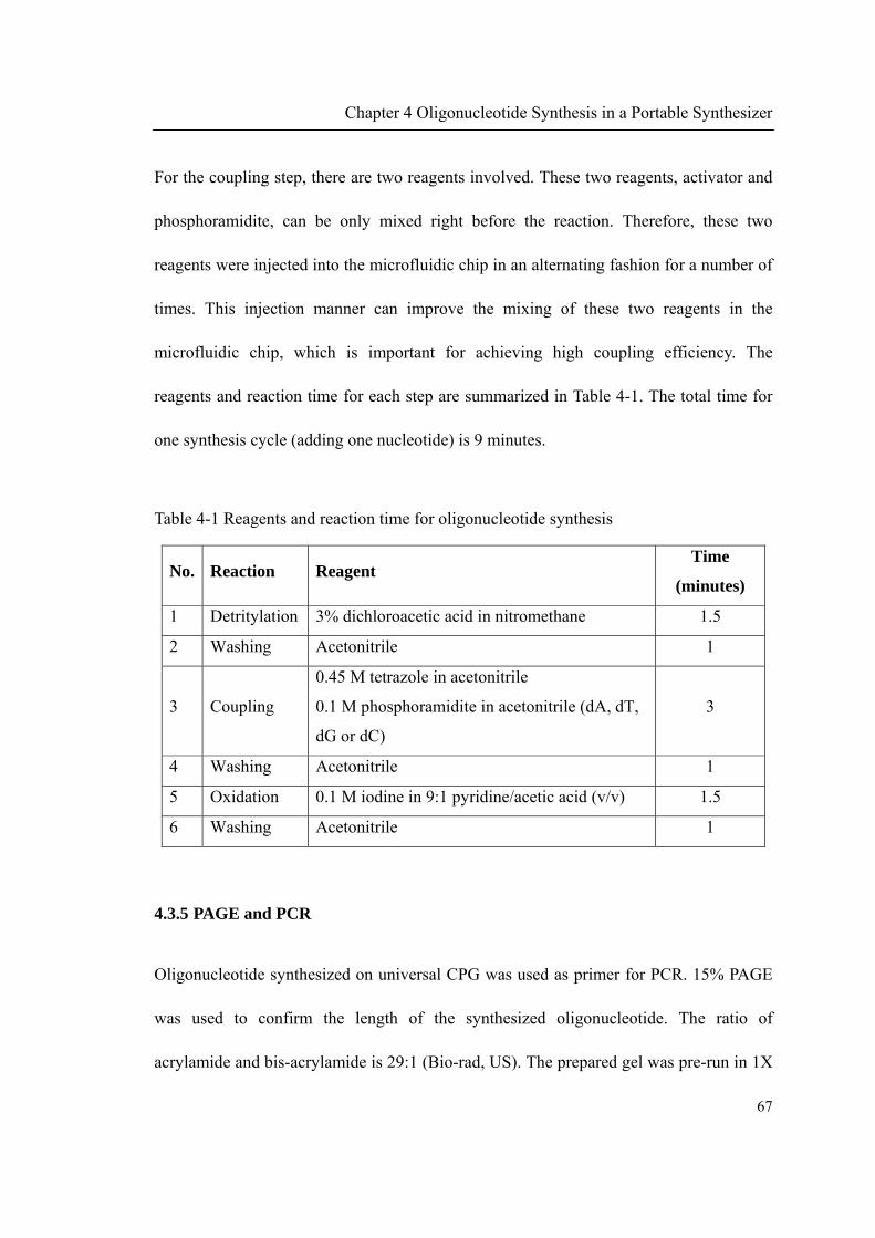
Chapter 4 Oligonucleotide Synthesis in a Portable Synthesizer
67
For the coupling step, there are two reagents involved. These two reagents, activator and
phosphoramidite, can be only mixed right before the reaction. Therefore, these two
reagents were injected into the microfluidic chip in an alternating fashion for a number of
times. This injection manner can improve the mixing of these two reagents in the
microfluidic chip, which is important for achieving high coupling efficiency. The
reagents and reaction time for each step are summarized in Table 4-1. The total time for
one synthesis cycle (adding one nucleotide) is 9 minutes.
Table 4-1 Reagents and reaction time for oligonucleotide synthesis
No. Reaction Reagent Time
(minutes)
1 Detritylation 3% dichloroacetic acid in nitromethane 1.5
2 Washing Acetonitrile 1
3 Coupling
0.45 M tetrazole in acetonitrile
0.1 M phosphoramidite in acetonitrile (dA, dT,
dG or dC)
3
4 Washing Acetonitrile 1
5 Oxidation 0.1 M iodine in 9:1 pyridine/acetic acid (v/v) 1.5
6 Washing Acetonitrile 1
4.3.5 PAGE and PCR
Oligonucleotide synthesized on universal CPG was used as primer for PCR. 15% PAGE
was used to confirm the length of the synthesized oligonucleotide. The ratio of
acrylamide and bis-acrylamide is 29:1 (Bio-rad, US). The prepared gel was pre-run in 1X

Chapter 4 Oligonucleotide Synthesis in a Portable Synthesizer
68
TBE buffer for 30 minutes at 200 V. The samples were heated to 95 °C for 2 minutes,
then immediately chilled by transferring onto ice. After that, the samples were added into
the wells and the electrophoresis was run for 1.5 hours at 200 V. Then the gel was stained
with SYBR® Gold dye and imaged with a G:BOX gel documentation system (Synoptics,
UK).
The synthesized oligonucleotide was used as reverse primer to amplify E. coli 16S
ribosomal RNA. The 596 bp PCR product was run in 1.7% agarose gel for 45 minutes at
120 V. The gel was also imaged with the G:BOX gel documentation system.
4.3.6 Probe deprotection and hybridization
Oligonucleotide probe was synthesized on a surface modified glass slide for hybridization.
After synthesis, the slide was treated with ethylenediamine:ethanol (1:1) for 2 hours at
room temperature to remove the protecting groups. It was then washed thoroughly with
ethanol followed by ddH2O and finally blown dry with nitrogen.
For hybridization, 5 M Texas Red labeled oligonucleotide was dissolved in 0.5X SSC
buffer containing 0.1% SDS. 15 L of the fluorescence labeled oligonucleotide was
spotted on the glass slide and then covered with cover slide. The hybridization was taken
place at 40 °C for 2 hours. After that, the glass slide was washed with 1X SSC buffer and

Chapter 4 Oligonucleotide Synthesis in a Portable Synthesizer
69
0.5X SSC buffer at 37 °C. The glass slide was then blown dry with compressed nitrogen.
The fluorescence image was taken by using a CCD color digital camera, Retiga 4000R
(QImaging), connected to a system microscope (Olympus BX41) with a mercury arc
(Olympus HBO103W/2) excitation source.
4.4 Result and discussion
4.4.1 PCR primer synthesis
To demonstrate whether oligonucleotide could be synthesized by the portable
oligonucleotide synthesis system and used as a primer for PCR, a 16-mer oligonucleotide
(sequence 5’-GGTTGCGCTCGTTGCG-3’) was synthesized on universal CPG. The
synthesized oligonucleotide was then cleaved from CPG by concentrated ammonium
hydroxide (28% in water) at 65 °C overnight. The synthesized oligonucleotide was used
as the reverse primer for amplifying E. coli 16S ribosomal RNA.
The oligonucleotide synthesized in the portable synthesizer was analyzed by PAGE.
Figure 4-7 shows the PAGE image of the synthesized oligonucleotide. From the PAGE
image, it can be seen that main product of the synthesized oligonucleotide is the 16-mer
full length oligonucleotide (lane 3), which has the same mobility as comparing with the
HPLC purified commercial oligonucleotide of the same sequence (lane 2). The main
impurity in the product is n-1 mer. By measuring the band intensity, the final yield of the

Chapter 4 Oligonucleotide Synthesis in a Portable Synthesizer
70
full length product was about 70%, corresponding to a step wise yield of 98%. This yield
was satisfactory and comparable with synthesis yield reported before [105]. The
synthesized primer of such yield is suitable for applications such as PCR without further
purification.
Figure 4-7 PAGE image for synthesized oligonucleotide length confirmation. Lane 1:
oligonucleotide ladder. Lane 2: HPLC purified commercial oligonucleotide with the same
sequence. Lane 3: oligonucleotide synthesized by the portable oligonucleotide synthesizer.
The synthesized 16-mer oligonucleotide was then used as reverse primer in PCR to
amplify E. coli 16S ribosomal RNA. The agarose gel electrophoresis image of the 596 bp
PCR product is shown in Figure 4-8. The sequence of the forward primer was 5’-
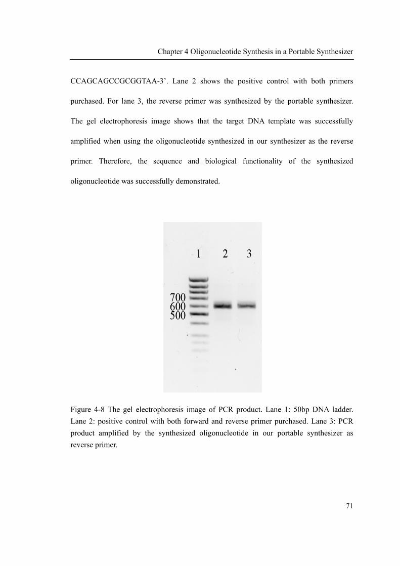
Chapter 4 Oligonucleotide Synthesis in a Portable Synthesizer
71
CCAGCAGCCGCGGTAA-3’. Lane 2 shows the positive control with both primers
purchased. For lane 3, the reverse primer was synthesized by the portable synthesizer.
The gel electrophoresis image shows that the target DNA template was successfully
amplified when using the oligonucleotide synthesized in our synthesizer as the reverse
primer. Therefore, the sequence and biological functionality of the synthesized
oligonucleotide was successfully demonstrated.
Figure 4-8 The gel electrophoresis image of PCR product. Lane 1: 50bp DNA ladder.
Lane 2: positive control with both forward and reverse primer purchased. Lane 3: PCR
product amplified by the synthesized oligonucleotide in our portable synthesizer as
reverse primer.

Chapter 4 Oligonucleotide Synthesis in a Portable Synthesizer
72
4.4.2 Probe synthesis
4.4.2.1 Probe for oligonucleotide hybridization
To further test the function of the portable oligonucleotide synthesizer, an oligonucleotide
probe (5’-GGTTGCGCTCGTTGCG-3’) was synthesized on surface modified glass slide.
After synthesis, the probe was hybridized with a complementary DNA which is labeled
with 6-carboxyfluorescein (6-FAM) fluorophore (5’-CGCAACGAGCGCAACC[6-
FAM]-3’). The fluorescence image was taken by using fluorescence microscope. The
fluorescence image in Figure 4-9 shows that the complementary DNA was successfully
hybridized to the synthesized oligonucleotide probe, which also confirmed the sequence
and biofunctionality of the synthesized oligonucleotide.
Figure 4-9 Fluorescence image of 6-FAM labeled complementary DNA hybridized to
synthesized probe
500 m
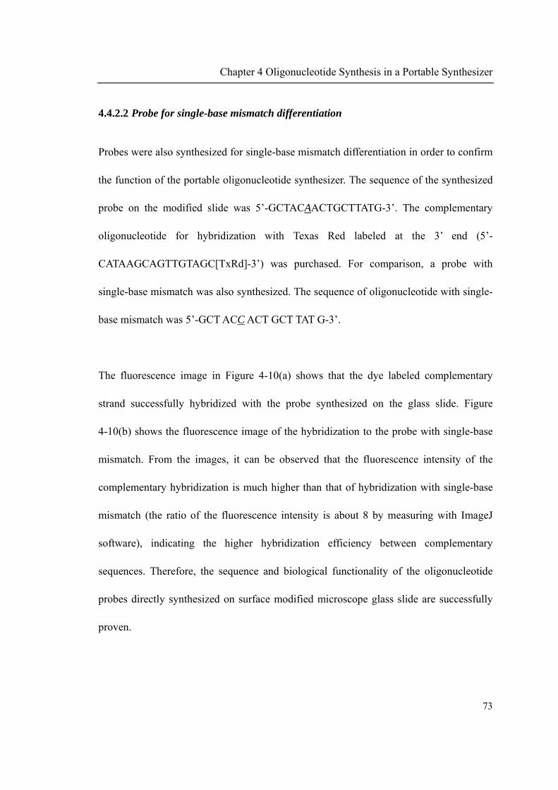
Chapter 4 Oligonucleotide Synthesis in a Portable Synthesizer
73
4.4.2.2 Probe for single-base mismatch differentiation
Probes were also synthesized for single-base mismatch differentiation in order to confirm
the function of the portable oligonucleotide synthesizer. The sequence of the synthesized
probe on the modified slide was 5’-GCTACAACTGCTTATG-3’. The complementary
oligonucleotide for hybridization with Texas Red labeled at the 3’ end (5’-
CATAAGCAGTTGTAGC[TxRd]-3’) was purchased. For comparison, a probe with
single-base mismatch was also synthesized. The sequence of oligonucleotide with single-
base mismatch was 5’-GCT ACC ACT GCT TAT G-3’.
The fluorescence image in Figure 4-10(a) shows that the dye labeled complementary
strand successfully hybridized with the probe synthesized on the glass slide. Figure
4-10(b) shows the fluorescence image of the hybridization to the probe with single-base
mismatch. From the images, it can be observed that the fluorescence intensity of the
complementary hybridization is much higher than that of hybridization with single-base
mismatch (the ratio of the fluorescence intensity is about 8 by measuring with ImageJ
software), indicating the higher hybridization efficiency between complementary
sequences. Therefore, the sequence and biological functionality of the oligonucleotide
probes directly synthesized on surface modified microscope glass slide are successfully
proven.
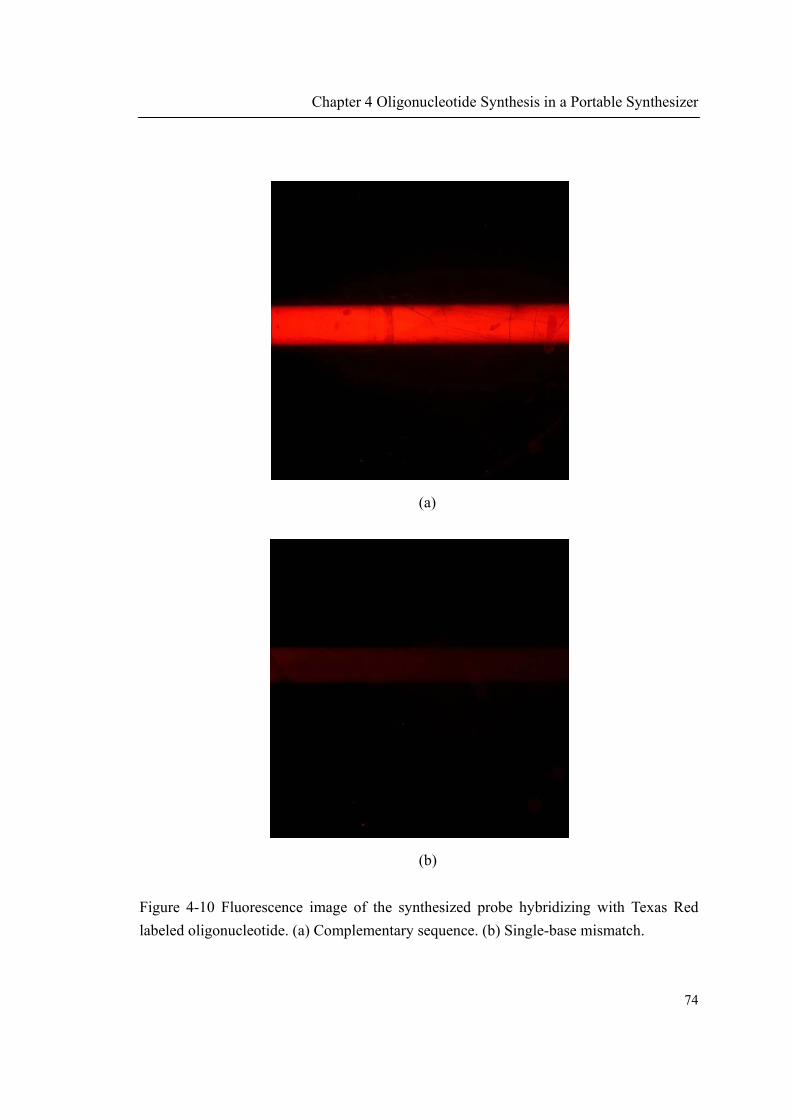
Chapter 4 Oligonucleotide Synthesis in a Portable Synthesizer
74
(a)
(b)
Figure 4-10 Fluorescence image of the synthesized probe hybridizing with Texas Red
labeled oligonucleotide. (a) Complementary sequence. (b) Single-base mismatch.
500 m
500 m

Chapter 4 Oligonucleotide Synthesis in a Portable Synthesizer
75
4.5 Conclusion
In this chapter, we presented a microfluidic device based portable oligonucleotide
synthesizer. To the best of our knowledge, this is the first portable oligonucleotide
synthesizer reported. The core component of the portable synthesizer is the zero dead-
volume microvalves integrated microfluidic chip which was designed in the previous
chapter. The portable oligonucleotide synthesizer was successfully used to synthesize
oligonucleotide primers. The length of the synthesized primer was confirmed by PAGE.
The primer was successfully used to amplify bacteria ribosomal RNA gene, therefore
proving the sequence and biofunctionality of the synthesized primer. Oligonucleotide
probe was also successfully synthesized on a flat glass surface by the portable synthesizer.
The sequence and biological functionality of the synthesized oligonucleotide probes were
demonstrated by DNA complementary and single-base mismatch hybridization
experiments. The time for synthesizing one base is 9 minutes and therefore 3 hours is
needed for a oligonucleotide with typical length of 20mer. The portable synthesizer
reported here has the potential capability of synthesizing oligonucleotide of any sequence
in the field.
76
CHAPTER 5
PORTABLE GENERIC DNA
HYBRIDIZATION BIOASSAY SYSTEM
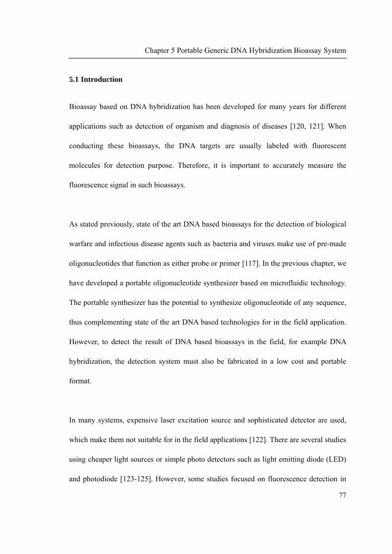
Chapter 5 Portable Generic DNA Hybridization Bioassay System
77
5.1 Introduction
Bioassay based on DNA hybridization has been developed for many years for different
applications such as detection of organism and diagnosis of diseases [120, 121]. When
conducting these bioassays, the DNA targets are usually labeled with fluorescent
molecules for detection purpose. Therefore, it is important to accurately measure the
fluorescence signal in such bioassays.
As stated previously, state of the art DNA based bioassays for the detection of biological
warfare and infectious disease agents such as bacteria and viruses make use of pre-made
oligonucleotides that function as either probe or primer [117]. In the previous chapter, we
have developed a portable oligonucleotide synthesizer based on microfluidic technology.
The portable synthesizer has the potential to synthesize oligonucleotide of any sequence,
thus complementing state of the art DNA based technologies for in the field application.
However, to detect the result of DNA based bioassays in the field, for example DNA
hybridization, the detection system must also be fabricated in a low cost and portable
format.
In many systems, expensive laser excitation source and sophisticated detector are used,
which make them not suitable for in the field applications [122]. There are several studies
using cheaper light sources or simple photo detectors such as light emitting diode (LED)
and photodiode [123-125]. However, some studies focused on fluorescence detection in

Chapter 5 Portable Generic DNA Hybridization Bioassay System
78
liquid phase instead of solid phase [123, 124]. In the other studies, DNA probes were
directly immobilized on the photodiode surface, limiting the reusability of the detector
[125].
In this chapter, we present the first portable generic DNA hybridization based bioassay
system. The system integrates the portable oligonucleotide synthesizer presented in the
previous chapter and a Texas Red fluorescence detection system based on a LED and
photodiode. The fluorescence detection system can detect Texas Red fluorophore as low
as 0.5 fmol and was successfully used for differentiating complementary and single-base
mismatch hybridization. The complete generic portable bioassay system was successfully
used to distinguish DNA from two different bacteria strains. The portable system has the
potential to detect any DNA sequence in the field.
5.2 System design
5.2.1 Texas Red fluorescence detection system
Figure 5-1(a) shows the schematic of the Texas Red fluorescence detection system. A
white color Luxeon Emitters (LXHL-PW01, Lumileds Lighting, US) was used as the
light source for excitation light. The LED was powered by a constant current Stardrive
LED driver (1 Watt, Sumatec Ltd, UK). The white light was first collimated by a lens
(f=30 mm, Edmund Optics, US) and then passed through an excitation filter (HQ575/50x,

Chapter 5 Portable Generic DNA Hybridization Bioassay System
79
Chroma, US). The filtered light was reflected by a beam splitter (Z594/750rpc, Chroma,
US) and focused onto the sample. The fluorescence emitted from the sample passed
through the emission filter (HQ645/70m-2p, Chroma, US) and was focused by a lens on a
high sensitivity, low noise photodiode detector with built-in pre-amplifier. (S8745-01,
Hamamatsu photonics, Japan). The photodiode was powered with ±6 V and the signal
from the pre-amplifier was directly measured with an NI 9219 Analog Input card
(National Instrument, US) without further amplification. All optical parts were fixed into
a home-made light tight aluminum housing. The photograph of the detection system is
shown in Figure 5-1(b). Spectrum of the various optical parts including LED, excitation
and emission filters, beam splitter, and photodiode can be seen in Appendix C.
5.2.2 Integration of fluorescence detection and oligonucleotide synthesis system
To build the portable generic DNA bioassay instrument, the fluorescence detection
system was further integrated into the portable oligonucleotide synthesizer developed in
previous chapter. As on-the-chip DNA hybridization is required, the microvalve
integrated microfluidic chip and the oligonucleotide probe synthesis reactor (as shown
previously in Figure 4-5) were both redesigned to incorporate the new function, as
described in the following.
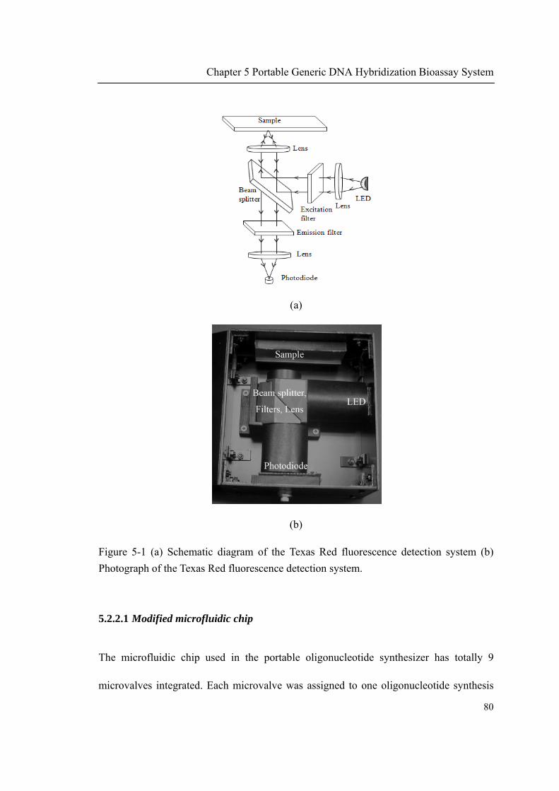
Chapter 5 Portable Generic DNA Hybridization Bioassay System
80
(a)
(b)
Figure 5-1 (a) Schematic diagram of the Texas Red fluorescence detection system (b)
Photograph of the Texas Red fluorescence detection system.
5.2.2.1 Modified microfluidic chip
The microfluidic chip used in the portable oligonucleotide synthesizer has totally 9
microvalves integrated. Each microvalve was assigned to one oligonucleotide synthesis

reagents. To
microfluidi
and washin
shown in
integrated
washing bu
plate of the
Figure 5-2 M
Microvalve
Detritylatio
microvalve
5.2.2.2 Rea
The oligonu
o realize the
ic chip to c
ng buffer (v
Figure 5-2
is shown
uffers) can
e aluminum
Microfluidi
e assignmen
on (9) Oxida
es integrated
actor for oli
ucleotide pr
Chapter 5
e integrated
ontrol hybr
valve 10). T
(a) and the
in Figure
be manuall
frame (can
(a)
ic chip for o
nt (1) Washi
ation (10) H
d.
igonucleotid
robe synthe
5 Portable G
d DNA hybr
ridization re
The assignm
e fabricated
5-2(b). Th
ly injected
be seen in F
oligonucleot
ing (2) Argo
Hybridizatio
de synthesis
esis reactor
Generic DN
ridization, o
elated reage
ment of mi
d microflui
he hybridiz
through an
Figure 5-4 p
tide synthes
on (3) Activ
on. (b) Fabri
is and hybri
designed pr
NA Hybridiz
one more va
ents such as
crovalves t
idic chip w
zation relate
injection p
part 13).
sis and DNA
vator (4) A (
icated micro
idization
reviously (F
zation Bioas
alve was add
s hybridizat
to different
with totally
ed reagents
port located
(b)
A hybridiza
5) T (6) G (
ofluidic chip
Figure 4-5(b
ssay System
81
ded into the
tion sample
reagents is
y 10 valves
s (samples
d on the top
ation. (a)
(7) C (8)
p with 10
b)) was also
m
1
e
e
s
s
,
p
o

Chapter 5 Portable Generic DNA Hybridization Bioassay System
82
modified to realize the on-site DNA hybridization. Comparing with the previous reactor,
the current one has two more elements, the temperature sensing and the heating parts.
The temperature sensor (PT100, RS) was sandwiched in between the top acrylic cover
and the microscopy glass slide on which the probe is synthesized (part 3 in Figure 5-3).
Thus the temperature measured is at the top surface of the glass slide and it is also the
surface on which the hybridization occurs. Therefore, the temperature measured is much
more accurate than placing the sensor elsewhere.
The heating unit was placed under the bottom acrylic case. A heater mat was placed on
the bottom surface of an aluminum piece (part 6 in Figure 5-3). The aluminum piece
directly contacted with the synthesis glass slide. Heat can be evenly distributed over the
aluminum piece, which can guarantee the uniform heating of the glass slide and increase
the temperature controlling accuracy. A hole was drilled into the aluminum piece to allow
excitation and emission light to pass through for fluorescence detection.

Chapter 5 Portable Generic DNA Hybridization Bioassay System
83
Figure 5-3 Design of oligonucleotide probe synthesis and hybridization reactor. (1) Top
acrylic cover with tubing access hole (2) PDMS microchannel (3) PT100 temperature
sensor (4) Surface modified glass slide (5) Bottom acrylic case (6) Heating unit with light
access hole. The whole assembly was held together by screw and then fixed inside the
fluorescence detection box.
5.2.2.3 Portable DNA bioassay system
The photograph of the complete portable generic DNA bioassay system is shown in
Figure 5-4. The fluorescence detection system was fixed inside the right partition
chamber of the original portable oligonucleotide synthesizer. The probe synthesis and
hybridization reactor was fixed on the upper wall inside the fluorescence detection device
(see part 9). The inlet of the reactor was directly connected to the outlet of the

Chapter 5 Portable Generic DNA Hybridization Bioassay System
84
microfluidic chip by FEP tubing. After probe synthesis, the hybridization reagent can be
manually injected into the reactor using a syringe through the port which was extended
outside the aluminum rack (see part 13, this injection port was controlled by valve 10 on
the microfluidic chip).
Figure 5-4 Photograph of the portable system: (1) PC with control software (2) Argon
tank (3) NI-DAQ (4) Solenoid valves and manifold (5) Pressure regulators (6) Vacuum
pump (7) Batteries (8) Microfluidic chip (9) Synthesis and hybridization reactor (10)
LED (11) Photodiode (12) Lenses, filters and beam splitter (13) Injection port for
hybridization related reagents.
42 cm
28 cm
19 cm

Chapter 5 Portable Generic DNA Hybridization Bioassay System
85
5.3 Materials and methods
5.3.1 Hybridization probe immobilization on glass slide
Hybridization probes were immobilized on glass slide for testing the function of
fluorescence detection unit. The glass slide was first cleaned with piranha solution
(sulfuric acid : hydrogen peroxide, 7:3) at 120 ºC for 30 minutes followed by thoroughly
washing with ddH2O. The cleaned glass slide reacted with 2% 3-
aminopropyltriethoxysilane (APTES) in acetone at room temperature for 2 hours and was
then baked in vacuum oven at 120 ºC for 1 hour. The glass surface was bearing amine
groups now. After that, 20 L of 50 mM disuccinimidyl suberate (DSS) in
dimethylformamide (DMF) was spotted on the amine functionalized glass slide and
covered with cover slide for 1 hour at room temperature. After washing with acetone,
1L of amine labeled oligonucleotide probe (10 M in 50 mM phosphate buffer pH 7.4)
was spotted on the activated surface for 2 hours. After washing, the slide was ready to use
for hybridization.
5.3.2 Asymmetric PCR
For bacteria strains differentiation, the bacteria genomic DNA (Bacillus cereus ATCC
14579 and Salmonella enterica subsp. enterica ATTC 13311) was first amplified by
asymmetric PCR. One primer is labeled with Texas Red fluorophore, thus the PCR
product containes the fluorophore for hybridization detection. The ratio of Texas Red

Chapter 5 Portable Generic DNA Hybridization Bioassay System
86
labeled primer and non-labeled primer was 10:1. Therefore, more fluorescence labeled
single-strand target DNA can be produced for hybridization and the competition between
the hybridization probe and the target-complementary strand can be reduced.
5.3.3 DNA hybridization
The hybridization of the Texas Red labeled PCR product to in situ synthesized probes
took place at 45 C for 1 hour in 5X SSC buffer containing 0.1% SDS. The temperature
was controlled by the integrated hybridization reactor. After hybridization, washing was
carried out with 0.1X SSC at 37 C for 5 minutes twice.
5.4 Result and discussion
5.4.1 Fluorescence detection system
5.4.1.1 System characterization
To characterize the Texas Red fluorescence detection system, a serial dilution of Texas
Red labeled oligonucleotide in water ranging from 1 nM to 500 nM was prepared. Then
0.5 μL of each dilution was spotted on glass slide (corresponding to 0.5 fmol to 250 fmol).
As the size of the spot was smaller than the size of the excitation light spot, all
fluorophores can be excited.
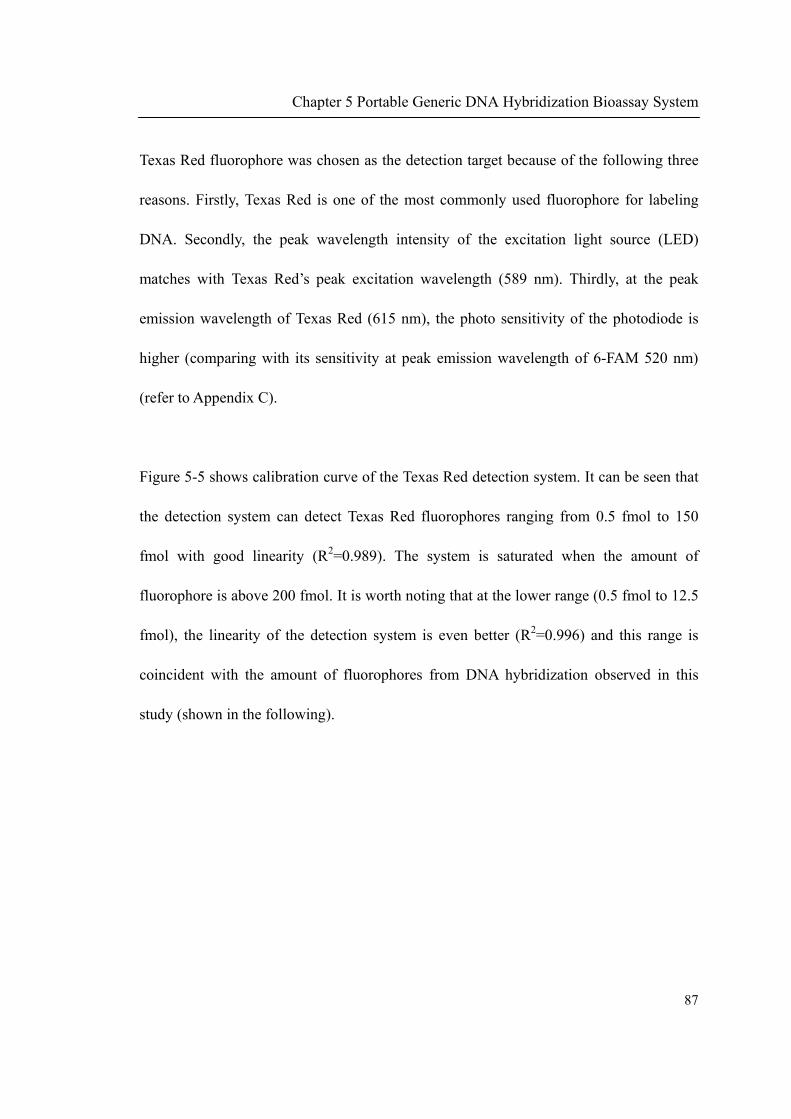
Chapter 5 Portable Generic DNA Hybridization Bioassay System
87
Texas Red fluorophore was chosen as the detection target because of the following three
reasons. Firstly, Texas Red is one of the most commonly used fluorophore for labeling
DNA. Secondly, the peak wavelength intensity of the excitation light source (LED)
matches with Texas Red’s peak excitation wavelength (589 nm). Thirdly, at the peak
emission wavelength of Texas Red (615 nm), the photo sensitivity of the photodiode is
higher (comparing with its sensitivity at peak emission wavelength of 6-FAM 520 nm)
(refer to Appendix C).
Figure 5-5 shows calibration curve of the Texas Red detection system. It can be seen that
the detection system can detect Texas Red fluorophores ranging from 0.5 fmol to 150
fmol with good linearity (R2=0.989). The system is saturated when the amount of
fluorophore is above 200 fmol. It is worth noting that at the lower range (0.5 fmol to 12.5
fmol), the linearity of the detection system is even better (R2=0.996) and this range is
coincident with the amount of fluorophores from DNA hybridization observed in this
study (shown in the following).

Chapter 5 Portable Generic DNA Hybridization Bioassay System
88
Figure 5-5 Calibration curve for Texas Red fluorescence detection system. The lower
range of the calibration curve (corresponding to amount of Texas Red fluorophore from
0.5 fmol to 12.5 fmol) is enlarged.
It was reported that the density of DNA probe immobilized on commercial ammine-
reactive glass slides was above 1012 probes/cm2 [126], corresponding to 1.66 ×10⁻⁵
fmol/µm2. Thus, by assuming 100% hybridization efficiency, our system can detect
hybridization to such probe surface with diameter as small as 200 µm.
5.4.1.2 Detection of complementary and single-base mismatch DNA hybridization
The fluorescence detection system was then tested by DNA hybridization to a surface

Chapter 5 Portable Generic DNA Hybridization Bioassay System
89
immobilized probe. Two amine labeled oligonucleotide probes (5’-
GCTACAACTGCTTATG[Amine]-3’ and 5’-GCTACCACTGCTTATG[Amine]-3’) were
immobilized on modified glass slide through DSS linker as described. These two
oligonucleotides have one base difference in the middle of the sequence. A Texas Red
labeled oligonucleotide (5’-CATAAGCAGTTGTAGC[TxRd]-3’), complementary to the
first oligonucleotide but with single-base mismatch to the second, was then hybridized to
both immobilized probes. After proper washing, the hybridization was measured by the
fluorescence detection system.
From the result of our system, the signal for complementary hybridization was 0.190 V.
However, the signal for single-base mismatch was just 0.018 V. The ratio of these two
signals is as large as 10.6, indicating that the fluorescence detection system successfully
discriminate the fluorescence signal from complementary and single-base mismatch
hybridization. A point to note is that both signals fall in the range where the system has
higher linearity.
For comparison, the fluorescence images of the complementary and single-base mismatch
hybridization were also taken by our fluorescent microscope system (Qimaging CCD
camera Retiga 4000R, and Olympus BX41 microscope) (Figure 5-6). The fluorescence
intensity was measured by using ImageJ software. The ratio of the fluorescence intensity
is 8.4, which is lower than the ratio of the signals measured by our fluorescence detection

system. Th
system is co
Figure 5-6
fluorescenc
mismatch h
5.4.2 Bacte
The functi
differentiati
illness from
ribosomal
produced m
his indicates
omparable t
6 Fluoresce
ce detectio
hybridizatio
erial differe
ion of the
ing differen
m Bacillus
RNA of th
more single
Chapter 5
s that at th
to and even
(a)
ence image
on system.
n.
entiation
complete
nt bacteria
spp. and s
hese two st
stranded ta
5 Portable G
his range, th
n slightly hig
of hybrid
(a) Com
portable D
strains. Tw
almonella s
trains were
arget DNA
Generic DN
he sensitivi
gher than th
dization to
mplementary
DNA bioas
wo bacteria
spp. were s
first ampli
for hybridi
NA Hybridiz
ity of our
hat of our m
(b
immobilize
y hybridiza
ssay instrum
strains that
selected in
ified by as
zation. In P
zation Bioas
fluorescenc
microscope s
b)
ed probes
ation (b)
ment was
may cause
this study
symmetric P
PCR, same
ssay System
90
ce detection
system.
for test of
Single-base
proved by
e foodborne
[120]. 16S
PCR which
primer pair
m
0
n
f
e
y
e
S
h
r
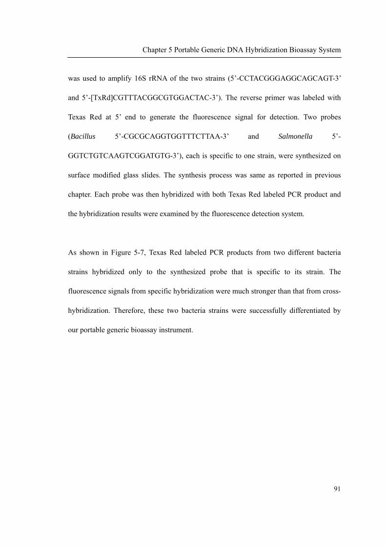
Chapter 5 Portable Generic DNA Hybridization Bioassay System
91
was used to amplify 16S rRNA of the two strains (5’-CCTACGGGAGGCAGCAGT-3’
and 5’-[TxRd]CGTTTACGGCGTGGACTAC-3’). The reverse primer was labeled with
Texas Red at 5’ end to generate the fluorescence signal for detection. Two probes
(Bacillus 5’-CGCGCAGGTGGTTTCTTAA-3’ and Salmonella 5’-
GGTCTGTCAAGTCGGATGTG-3’), each is specific to one strain, were synthesized on
surface modified glass slides. The synthesis process was same as reported in previous
chapter. Each probe was then hybridized with both Texas Red labeled PCR product and
the hybridization results were examined by the fluorescence detection system.
As shown in Figure 5-7, Texas Red labeled PCR products from two different bacteria
strains hybridized only to the synthesized probe that is specific to its strain. The
fluorescence signals from specific hybridization were much stronger than that from cross-
hybridization. Therefore, these two bacteria strains were successfully differentiated by
our portable generic bioassay instrument.
Chapter 5 Portable Generic DNA Hybridization Bioassay System
92
Figure 5-7 3D bar graph showing the fluorescence signal from specific and cross
hybridization between PCR products of two different bacteria strains and synthesized
strain specific probes.
It can also been seen that the fluorescence signals from specific hybridization were not as
high as that from previous hybridization between oligonucleotide and oligonucleotide
(5.4.1.2). This could be due to the fact that the PCR product has a length of 475-mer. The
hybridization efficiency can be affected by the length of the hybridization target [127].
Longer PCR product can lower the hybridization efficiency, leading to smaller
fluorescence signals. However, the signals are still within the detection range where the
system has higher linearity.
Chapter 5 Portable Generic DNA Hybridization Bioassay System
93
5.5 Conclusion
In this chapter, we have developed a portable and generic DNA bioassay instrument. To
the best of our knowledge, this is the first portable system developed for in situ synthesis
of oligonucleotide probe and integrated detection of DNA hybridization. The portable
oligonucleotide synthesizer is capable of synthesizing probe of any sequence on demand.
The Texas Red fluorescence detection device, based on a LED excitation light source and
a photodiode detector, can detect Texas Red fluorophore of the amount down to 0.5 fmol
and is able to discriminate complementary and single-base mismatch DNA hybridization.
The complete system was successfully used to distinguish different bacteria strains by
synthesizing strain specific probes and detecting the hybridization signals within the
portable instrument. The system presented in this work has the potential to detect any
DNA sequence in the field. We envisage that our system could help to enable fast
responses to emerging bio-threats for homeland security and in pandemics.

94
CHAPTER 6
CONCLUSION
Chapter 6 Conclusion
95
6.1 Conclusion and original contributions
This work focused on the development of a portable oligonucleotide synthesizer and
generic DNA hybridization based bioassay instrument due to the emerging need of in the
field synthesis of DNA oligonucleotide and in situ detection of specific DNA sequence.
In the following paragraphs, the important findings that were obtained in this work are
outlined.
The first part of this study was concerned with designing a microvalves integrated
microfluidic chip. The distinct advantage of the developed microchip is that it has a zero
dead-volume characteristic. This property is attributed to the special design of the zigzag
shaped main channel and the microvalves were located exactly at each turning point of
the zigzag shaped main channel. This design removed the connecting channels which are
found in previous designs. The absence of the connecting channels eliminated the
possibility of liquid reagents trapped within the microdevice, which could lead to cross
contamination to subsequently added reagents. The zero dead-volume characteristic of
the microdevice was proven by using PCR to detect trace amount of DNA template
molecules left in the device after washing. The result showed that cross contamination of
reagents in our microdevice design can be minimized to ppm levels after 30 seconds
washing, which is more efficient when comparing with traditional design. We believe that
the microdevice developed here is extremely useful for applications in which cross
contamination is a critical issue and lead to unpredictable results. DNA oligonucleotide

Chapter 6 Conclusion
96
synthesis is such an application in which cross contamination among reagents makes
successful synthesis of oligonucleotides problematic.
The second part of this work concentrated on developing a portable oligonucleotide
synthesizer with the zero dead-volume microfluidic device that was obtained in the first
part of this work as the core component. The portable synthesizer consists of three main
parts: electronic & electrical part, pneumatic part and fluidic part. The synthesis
controlling software was developed with LabVIEW to control and monitor the whole
synthesis process. All components forming the portable synthesizer were fixed within a
home-made aluminum rack. The rack had a dimension of 42 cm × 19 cm × 28 cm and 6
kg of weight and can be inserted into a suitcase for ease of carrying. The function of the
portable oligonucleotide synthesizer was proven by synthesizing both oligonucleotide
primers and probes. The primers synthesized were analyzed by PAGE to confirm the
length. The sequence and biological functionality of the synthesized primers were
successfully demonstrated by amplifying E.coli 16S ribosomal RNA. The synthesized
probes were successfully used for DNA hybridization and had the ability to differentiate
complementary and single-base mismatch sequence, which further confirmed the
sequence and biological functionality of the synthesized probes. In summary, the
developed portable synthesizer is capable of synthesizing an oligonucleotide with any
sequence on demand as either primer or probe. As far as we know, this is the first portable
oligonucleotide synthesizer reported.

Chapter 6 Conclusion
97
The third part of this work was concerned with developing a portable generic DNA
hybridization based bioassay system. A fluorescence detection unit was designed and
integrated into the portable synthesizer to form the generic bioassay system. The
fluorescence detection unit, using an ultra bright LED as the excitation source and a high-
sensitivity photodiode as the detector, was capable of detecting Texas Red fluorophore of
amounts ranging from 0.5 fmol to 150 fmol. The detection unit had a good linearity at
this range of Texas Red fluorophore amount and even a better linearity at the lower range,
which was also coincident with the amount of fluorophores from DNA hybridization
experiments. The Complementary and single-base mismatch hybridization were easily
discriminated by using the fluorescence detection unit. The complete bioassay system,
formed by integrating the portable oligonucleotide synthesizer and the fluorescence
detection system, was successfully used to differentiate two bacteria strains by in situ
synthesis of strain specific probes, hybridization to Texas Red labeled amplicons and then
on site detection of the fluorescence signals. To the best of our knowledge, no such
generic and portable DNA hybridization bioassay system was reported previously. As the
system has the potential to detect DNA target of any sequence for in the field applications,
we envisage that our system could help to enable fast responses to emerging bio-threats
for homeland security and in pandemics.
Chapter 6 Conclusion
98
6.2 Technical challenges
PDMS is one of the widely used polymeric materials for fabrication of microfluidic
device. However, it can be badly swelled by organic solvent used in oligonucleotide
synthesis such as dichloromethane in detritylation reaction and tetrahydrofuran in
oxidation reaction. To overcome this problem, these traditionally used reagents were
replaced. For detritylation reaction, dichloroacetic acid was dissolve in nitromethane,
which does not swell PDMS, instead of dichloromethane. For oxidation reaction, iodine
was dissolved in pyridine/acetic acid mixture instead of THF/Pyridine/H2O mixture. The
replace of traditional oligonucleotide synthesis reagents does not affect the synthesis
yield as the step wise yield is 98%, which is comparable to yield reported before [105].
In building the portable oligonucleotide synthesizer, the size of each component is critical.
As microvalve and liquid reagents are both controlled by argon gas pressure, a gas tank
must be integrated into the system. However, the pressurized gas tank used in laboratory
is too big and too heavy to integrate into the portable system. We finally adapted the gas
tank which is used in paintball game into our portable system. The Output pressure from
the paintball tank (~450 psi) is first regulated to 20 psi by a paintball tank regulator and
then regulated to pressures needed in the portable system. The use of paintball tank in the
system dramatically reduces the size and weight of the complete system.
Chapter 6 Conclusion
99
6.3 Future works
In the present work, single oligonucleotide was synthesized at one time in current system
design. However, the system can be easily extended due to the flexibility of the system
design and modular configuration of electronic and pneumatic hardware. One future work
could be simultaneously synthesizing multiple oligonucleotides within the portable
oligonucleotide synthesizer, which can significantly improve the throughput of the
portable system.
This task could be done by designing a new synthesis reactor in which microvalves are
integrated. The microvalves within the synthesis reactor can be used to selectively deliver
synthesis reagents to certain reaction chambers (especially different phosphoramidite
monomers during coupling reaction. All other reactions are universal regardless of the
sequence to be synthesized, thus no selective delivery of reagents is required). The
coupling reactor will occur in the chambers where coupling reagents are delivered.
Therefore, multiple oligonucleotides with different sequence could be obtained by the
proposed new reactor.
Another possible way to simultaneously synthesize multiple oligonucleotides, especially
for oligonucleotide probe, is to adopt a photochemical synthesis approach (reviewed in
2.1.2.3). A selective light excitation unit, such as an addressable LED array, could be
designed and incorporated into the system. The excitation unit could selectively activate
Chapter 6 Conclusion
100
certain regions on the flat solid support surface to remove the 5’-OH protecting group.
The surface area with proper activation could then couple with the incoming
phosphoramidite. Therefore multiple in situ synthesized oligonucleotide probes could be
obtained.

Bibliography
101
BIBLIOGRAPHY
1. Kricka, L. and P. Wilding, Microchip PCR. Anal. Bioanal. Chem., 2003. 377(5): p.
820-825.
2. Heller, M.J., DNA microarray technology: devices, systems, and applications.
Annu. Rev. Biomed. Eng., 2002. 4: p. 129-153.
3. Tian, J., K. Ma and I. Saaem, Advancing high-throughput gene synthesis
technology. Mol. BioSyst., 2009. 5(7): p. 714-722.
4. Michelson, A.M. and S.A.R. Todd, Nucleotides part XXXII. Synthesis of a
dithymidine dinucleotide containing a 3: 5-internucleotidic linkage. J. Chem. Soc.,
1955: p. 2632-2638.
5. Gait, M.J., ed. Oligonucleotide Synthesis: A Practical Approach. Practical
Approach Series. 1984, IRL PRESS: Oxford.
6. Rayner, S., S. Brignac, R. Bumeister, Y. Belosludtsev, T. Ward, O.d. Grant, K.
O'Brien, G.A. Evans and H.R. Garner, MerMade: An Oligodeoxyribonucleotide
Synthesizer for High Throughput Oligonucleotide Production in Dual 96-Well
plates. Genome Res., 1998. 8(7): p. 741-747.
7. Cheng, J.-Y., H.-H. Chen, Y.-S. Kao, W.-C. Kao and K. Peck, High throughput
parallel synthesis of oligonucleotides with 1536 channel synthesizer. Nucleic
Acids Res., 2002. 30(18): p. e93-.
8. Marcus, J.S., W.F. Anderson and S.R. Quake, Microfluidic Single-Cell mRNA
Isolation and Analysis. Anal. Chem., 2006. 78(9): p. 3084-3089.
9. Wu, L., Y. Zhang, M. Palaniapan and P. Roy, Wall effects in continuous
microfluidic magneto-affinity cell separation. Biotechnology and Bioengineering,
2010. 106(1): p. 68-75.
10. Lin, Z., T. Cherng-Wen, P. Roy and D. Trau, In-situ measurement of cellular
microenvironments in a microfluidic device. Lab Chip, 2009. 9: p. 257-262.

Bibliography
102
11. Song, Y., H. Modrow, L.L. Henry, C.K. Saw, E.E. Doomes, V. Palshin, J. Hormes
and C.S.S.R. Kumar, Microfluidic Synthesis of Cobalt Nanoparticles. Chemistry
of Materials, 2006. 18(12): p. 2817-2827.
12. Hong, J.W., V. Studer, G. Hang, W.F. Anderson and S.R. Quake, A nanoliter-scale
nucleic acid processor with parallel architecture. Nat. Biotechnol., 2004. 22(4): p.
435-439.
13. Green, E.K., Allele-Specific Oligonucleotide PCR. 2002, Humana Press. p. 47-50.
14. Rouillard, J.-M., W. Lee, G. Truan, X. Gao, X. Zhou and E. Gulari, Gene2Oligo:
oligonucleotide design for in vitro gene synthesis. Nucleic Acids Res., 2004.
32(suppl_2): p. W176-180.
15. Riordan, M.L. and J.C. Martin, Oligonucleotide-based therapeutics. Nature, 1991.
350(6317): p. 442-443.
16. Khorana, H.G., G.M. Tener, J.G. Moffat and E.H. Pol, A new approach to
synthesis of polynucleotides. Chem. and Ind., 1956: p. 1523.
17. Khorana, H.G., W.E. Razzell, P.T. Gilham, G.M. Tener and E.H. Pol, Syntheses of
Dideoxyribonucleotides. J. Am. Chem. Soc., 1957. 79(4): p. 1002-1003.
18. Gilham, P.T. and H.G. Khorana, Studies on Polynucleotides. I. A New and
General Method for the Chemical Synthesis of the C5'-C3' Internucleotidic
Linkage. Syntheses of Deoxyribo-dinucleotides. J. Am. Chem. Soc., 1958. 80(23):
p. 6212-6222.
19. Agarwal, K.L., A. Yamazaki, P.J. Cashion and H.G. Khorana, Chemical Synthesis
of Polynucleotides. Angew. Chem. Int. Ed., 1972. 11(6): p. 451-459.
20. Schaller, H., G. Weimann, B. Lerch and H.G. Khorana, Studies on
Polynucleotides. XXIV. The Stepwise Synthesis of Specific
Deoxyribopolynucleotides. Protected Derivatives of Deoxyribonucleosides and
New Syntheses of Deoxyribonucleoside-3' Phosphates. J. Am. Chem. Soc., 1963.
85(23): p. 3821-3827.
21. Khorana, H.G., Nucleic acid synthesis. Pure Appl. Chem., 1968. 17: p. 349-382.

Bibliography
103
22. Khorana, H.G., Synthesis in the study of nucleic acids. The Fourth Jubilee Lecture.
Biochem. J., 1968. 109: p. 709-725.
23. Letsinger, R.L. and V. Mahadevan, Oligonucleotide Synthesis on a Polymer
Support. J. Am. Chem. Soc., 1965. 87(15): p. 3526-3527.
24. Letsinger, R.L., K.K. Ogilvie and P.S. Miller, Nucleotide chemistry. XV.
Developments in syntheses of oligodeoxyribonucleotides and their organic
derivatives. J. Am. Chem. Soc., 1969. 91(12): p. 3360-3365.
25. Hall, R.H., A. Todd and R.F. Webb, Nucleotides. Part XLI. Mixed anhydrides as
intermediates in the synthesis of dinucleoside phosphates. J. Chem. Soc., 1957: p.
3291-3296.
26. Froehler, B.C. and M.D. Matteucci, Nucleoside h-phosphonates: Valuable
intermediates in the synthesis of deoxyoligonucleotides. Tetrahedron Lett., 1986.
27(4): p. 469-472.
27. Froehler, B.C., P.G. Ng and M.D. Matteucci, Synthesis of DNA via
deoxynudeoside H-phosphonate Intermediates. Nucleic Acids Res., 1986. 14(13):
p. 5399-5407.
28. Matsukura, M., K. Shinozuka, G. Zon, H. Mitsuya, M. Reitz, J.S. Cohen and S.
Broder, Phosphorothioate analogs of oligodeoxynucleotides: inhibitors of
replication and cytopathic effects of human immunodeficiency virus. Proc. Natl.
Acad. Sci. U. S. A. , 1987. 84(21): p. 7706-7710.
29. Froehler, B.C., Deoxynucleoside H-Phosphonate diester intermediates in the
synthesis of internucleotide phosphate analogues. Tetrahedron Lett., 1986. 27(46):
p. 5575-5578.
30. Letsinger, R.L. and W.B. Lunsford, Synthesis of thymidine oligonucleotides by
phosphite triester intermediates. J. Am. Chem. Soc., 1976. 98(12): p. 3655-3661.
31. Beaucage, S.L. and M.H. Caruthers, Deoxynucleoside phosphoramidites--A new
class of key intermediates for deoxypolynucleotide synthesis. Tetrahedron Lett.,
1981. 22(20): p. 1859-1862.
32. Narang, S.A., ed. Synthesis and applications of DNA and RNA. 1987, Academic

Bibliography
104
Press: Orlando.
33. Matteucci, M.D. and M.H. Caruthers, Synthesis of deoxyoligonucleotides on a
polymer support. J. Am. Chem. Soc., 1981. 103(11): p. 3185-3191.
34. Gough, G.R., M.J. Brunden and P.T. Gilham, Recovery and recycling of synthetic
units in the construction of oligodeoxyribonucleotides on solid supports.
Tetrahedron Lett., 1981. 22(42): p. 4177-4180.
35. McCollum, C. and A. Andrus, An optimized polystyrene support for rapid,
efficient oligonucleotide synthesis. Tetrahedron Lett., 1991. 32(33): p. 4069-4072.
36. H. Köster, H., A. Stumpe and A. Wolter, Polymer support oligonucleotide
synthesis 13: Rapid and efficient synthesis of oligodeoxynucleotides on porous
glass support using triester approach. Tetrahedron Lett., 1983. 24(8): p. 747-750.
37. Pon, R.T., Solid-Phase Supports for Oligonucleotide Synthesis, in Protocols for
Oligonucleotides and Analogs. 1993. p. 465-496.
38. Sproat, B.S. and D.M. Brown, A new linkage for solid phase synthesis of
oligodeoxyribonucleotides. Nucleic Acids Res, 1985. 13(8): p. 2979-87.
39. Pon, R.T., N. Usman and K.K. Ogilvie, Derivatization of Controlled Pore Glass
Beads for Solid Phase Oligonucleotide Synthesis. Biotechniques, 1988. 6(8): p.
768-775.
40. Lyttle, M.H., D. Hudson and R.M. Cook, A new universal linker for solid phase
DNA synthesis. Nucleic Acids Res., 1996. 24(14): p. 2793-2798.
41. Guzaev, A.P. and M. Manoharan, A Conformationally Preorganized Universal
Solid Support for Efficient Oligonucleotide Synthesis. J. Am. Chem. Soc., 2003.
125(9): p. 2380-2381.
42. Azhayev, A.V. and M.L. Antopolsky, Amide group assisted 3'-dephosphorylation
of oligonucleotides synthesized on universal A-supports. Tetrahedron, 2001.
57(23): p. 4977-4986.
43. Roberts, L., HUMAN GENOME RESEARCH:SNP Mappers Confront Reality and
Find It Daunting. Science, 2000. 287(5460): p. 1898-1899.

Bibliography
105
44. Lai, E., Application of SNP Technologies in Medicine: Lessons Learned and
Future Challenges. Genome Res., 2001. 11(6): p. 927-929.
45. Lashkari, D.A., S.P. Hunicke-Smith, R.M. Norgren, R.W. Davis and T. Brennan,
An automated multiplex oligonucleotide synthesizer: development of high-
throughput, low-cost DNA synthesis. Proc. Natl. Acad. Sci. U. S. A., 1995. 92(17):
p. 7912-5.
46. Hughes, T.R., M. Mao, A.R. Jones, J. Burchard, M.J. Marton, K.W. Shannon, S.M.
Lefkowitz, M. Ziman, J.M. Schelter, M.R. Meyer, S. Kobayashi, C. Davis, H. Dai,
Y.D. He, S.B. Stephaniants, G. Cavet, W.L. Walker, A. West, E. Coffey, D.D.
Shoemaker, R. Stoughton, A.P. Blanchard, S.H. Friend and P.S. Linsley,
Expression profiling using microarrays fabricated by an ink-jet oligonucleotide
synthesizer. Nat. Biotechnol., 2001. 19(4): p. 342-347.
47. Butler, J.H., M. Cronin, K.M. Anderson, G.M. Biddison, F. Chatelain, M.
Cummer, D.J. Davi, L. Fisher, A.W. Frauendorf, F.W. Frueh, C. Gjerstad, T.F.
Harper, S.D. Kernahan, D.Q. Long, M. Pho, J.A. Walker and T.M. Brennan, In
Situ Synthesis of Oligonucleotide Arrays by Using Surface Tension. J. Am. Chem.
Soc., 2001. 123(37): p. 8887-8894.
48. Xiao, P.F., N.Y. He, Z.C. Liu, Q.G. He, X. Sun and Z.H. Lu, In situ synthesis of
oligonucleotide arrays by using soft lithography. Nanotechnology, 2002. 13(6): p.
756-762.
49. Beier, M. and J.D. Hoheisel, Production by quantitative photolithographic
synthesis of individually quality checked DNA microarrays. Nucleic Acids Res.,
2000. 28(4): p. e11-.
50. Luebke, K.J., R.P. Balog and H.R. Garner, Prioritized selection of
oligodeoxyribonucleotide probes for efficient hybridization to RNA transcripts.
Nucleic Acids Res., 2003. 31(2): p. 750-758.
51. Gao, X., E. LeProust, H. Zhang, O. Srivannavit, E. Gulari, P. Yu, C. Nishiguchi, Q.
Xiang and X. Zhou, A flexible light-directed DNA chip synthesis gated by
deprotection using solution photogenerated acids. Nucleic Acids Res., 2001.
29(22): p. 4744-4750.

Bibliography
106
52. Zhou, X., S. Cai, A. Hong, Q. You, P. Yu, N. Sheng, O. Srivannavit, S. Muranjan,
J.M. Rouillard, Y. Xia, X. Zhang, Q. Xiang, R. Ganesh, Q. Zhu, A. Matejko, E.
Gulari and X. Gao, Microfluidic PicoArray synthesis of oligodeoxynucleotides
and simultaneous assembling of multiple DNA sequences. Nucleic Acids Res.,
2004. 32(18): p. 5409-5417.
53. Nie, Z., W. Li, M. Seo, S. Xu and E. Kumacheva, Janus and Ternary Particles
Generated by Microfluidic Synthesis: Design, Synthesis, and Self-Assembly. J. Am.
Chem. Soc., 2006. 128(29): p. 9408-9412
54. Sia, S.K. and G.M. Whitesides, Microfluidic devices fabricated in
Poly(dimethylsiloxane) for biological studies. Electrophoresis, 2003. 24(21): p.
3563-3576.
55. Guo-Hua, F. and K. Eun Sok, Micropump based on PZT unimorph and one-way
parylene valves. J. Micromech. Microeng. , 2004. 14(4): p. 429.
56. Brian, K.P. and T. Tyson, Comparison of two passive microvalve designs for
microlamination architectures. J. Micromech. Microeng. , 2000. 10(1): p. 15.
57. Yamahata, C., F. Lacharme, Y. Burri and M.A.M. Gijs, A ball valve micropump in
glass fabricated by powder blasting. Sens. Actuators, B, 2005. 110(1): p. 1-7.
58. Ahn, C.H., C. Jin-Woo, G. Beaucage, J.H. Nevin, L. Jeong-Bong, A. Puntambekar
and J.Y. Lee, Disposable smart lab on a chip for point-of-care clinical diagnostics.
Proceedings of the IEEE, 2004. 92(1): p. 154-173.
59. Leu, T.-S. and P.-Y. Chang, Pressure barrier of capillary stop valves in micro
sample separators. Sens. Actuators, A, 2004. 115(2-3): p. 508-515.
60. Kwang, W.O. and H.A. Chong, A review of microvalves. J. Micromech. Microeng.,
2006. 16(5): p. R13.
61. Choi, J.-W., K.W. Oh, A. Han, C.A. Wijayawardhana, C. Lannes, S. Bhansali, K.T.
Schlueter, W.R. Heineman, H.B. Halsall, J.H. Nevin, A.J. Helmicki, H.T.
Henderson and C.H. Ahn, Development and Characterization of Microfluidic
Devices and Systems for Magnetic Bead-Based Biochemical Detection. Biomed
Microdevices, 2001. 3(3): p. 191-200.

Bibliography
107
62. Choi, J.-W., K.W. Oh, J.H. Thomas, W.R. Heineman, H.B. Halsall, J.H. Nevin,
A.J. Helmicki, H.T. Henderson and C.H. Ahn, An integrated microfluidic
biochemical detection system for protein analysis with magnetic bead-based
sampling capabilities. Lab Chip, 2002. 2: p. 27-30.
63. Fu, C. and et al., Magnetically driven micro ball valves fabricated by multilayer
adhesive film bonding. J. Micromech. Microeng. , 2003. 13(4): p. S96.
64. Meckes, A., J. Behrens, O. Kayser, W. Benecke, T. Becker and G. Müller,
Microfluidic system for the integration and cyclic operation of gas sensors. Sens.
Actuators, A, 1999. 76(1-3): p. 478-483.
65. Goll, C. and et al., An electrostatically actuated polymer microvalve equipped
with a movable membrane electrode. J. Micromech. Microeng. , 1997. 7(3): p.
224.
66. Sato, K. and M. Shikida, An electrostatically actuated gas valve with an S-shaped
film element. J. Micromech. Microeng. , 1994. 4(4): p. 205.
67. Rogge, T., Z. Rummler and W.K. Schomburg, Polymer micro valve with a
hydraulic piezo-drive fabricated by the AMANDA process. Sens. Actuators, A,
2004. 110(1-3): p. 206-212.
68. Peige, S. and et al., Polymer micro piezo valve with a small dead volume. J.
Micromech. Microeng. , 2004. 14(2): p. 305.
69. Jerman, H., Electrically activated normally closed diaphragm valves. J.
Micromech. Microeng. , 1994. 4(4): p. 210.
70. Barth, P.W. Silicon Microvalves For Gas Flow Control. in Solid-State Sensors and
Actuators, 1995 and Eurosensors IX.. Transducers '95. The 8th International
Conference on. 1995.
71. Takao, H., K. Miyamura, H. Ebi, M. Ashiki, K. Sawada and M. Ishida, A MEMS
microvalve with PDMS diaphragm and two-chamber configuration of thermo-
pneumatic actuator for integrated blood test system on silicon. Sens. Actuators, A,
2005. 119(2): p. 468-475.
72. Kim, J.-H., K.-H. Na, C.J. Kang, D. Jeon and Y.-S. Kim, A disposable
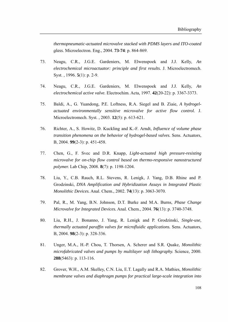
Bibliography
108
thermopneumatic-actuated microvalve stacked with PDMS layers and ITO-coated
glass. Microelectron. Eng., 2004. 73-74: p. 864-869.
73. Neagu, C.R., J.G.E. Gardeniers, M. Elwenspoek and J.J. Kelly, An
electrochemical microactuator: principle and first results. J. Microelectromech.
Syst. , 1996. 5(1): p. 2-9.
74. Neagu, C.R., J.G.E. Gardeniers, M. Elwenspoek and J.J. Kelly, An
electrochemical active valve. Electrochim. Acta, 1997. 42(20-22): p. 3367-3373.
75. Baldi, A., G. Yuandong, P.E. Loftness, R.A. Siegel and B. Ziaie, A hydrogel-
actuated environmentally sensitive microvalve for active flow control. J.
Microelectromech. Syst. , 2003. 12(5): p. 613-621.
76. Richter, A., S. Howitz, D. Kuckling and K.-F. Arndt, Influence of volume phase
transition phenomena on the behavior of hydrogel-based valves. Sens. Actuators,
B, 2004. 99(2-3): p. 451-458.
77. Chen, G., F. Svec and D.R. Knapp, Light-actuated high pressure-resisting
microvalve for on-chip flow control based on thermo-responsive nanostructured
polymer. Lab Chip, 2008. 8(7): p. 1198-1204.
78. Liu, Y., C.B. Rauch, R.L. Stevens, R. Lenigk, J. Yang, D.B. Rhine and P.
Grodzinski, DNA Amplification and Hybridization Assays in Integrated Plastic
Monolithic Devices. Anal. Chem., 2002. 74(13): p. 3063-3070.
79. Pal, R., M. Yang, B.N. Johnson, D.T. Burke and M.A. Burns, Phase Change
Microvalve for Integrated Devices. Anal. Chem., 2004. 76(13): p. 3740-3748.
80. Liu, R.H., J. Bonanno, J. Yang, R. Lenigk and P. Grodzinski, Single-use,
thermally actuated paraffin valves for microfluidic applications. Sens. Actuators,
B, 2004. 98(2-3): p. 328-336.
81. Unger, M.A., H.-P. Chou, T. Thorsen, A. Scherer and S.R. Quake, Monolithic
microfabricated valves and pumps by multilayer soft lithography. Science, 2000.
288(5463): p. 113-116.
82. Grover, W.H., A.M. Skelley, C.N. Liu, E.T. Lagally and R.A. Mathies, Monolithic
membrane valves and diaphragm pumps for practical large-scale integration into

Bibliography
109
glass microfluidic devices. Sens. Actuators, B, 2003. 89(3): p. 315-323.
83. Willis, P.A., B.D. Hunt, V.E. White, M.C. Lee, M. Ikeda, S. Bae, M.J. Pelletier
and F.J. Grunthaner, Monolithic Teflon[registered sign] membrane valves and
pumps for harsh chemical and low-temperature use. Lab Chip, 2007. 7(11): p.
1469-1474.
84. Grover, W.H., M.G.v. Muhlen and S.R. Manalis, Teflon films for chemically-inert
microfluidic valves and pumps. Lab Chip, 2008. 8(6): p. 913-918.
85. Vieider, C., O. Ohman and H. Elderstig. A pneumatically actuated micro valve
with a silicone rubber membrane for integration with fluid-handling systems. in
Solid-State Sensors and Actuators, 1995 and Eurosensors IX.. Transducers '95.
The 8th International Conference on. 1995.
86. Takao, H. and M. Ishida, Microfluidic integrated circuits for signal processing
using analogous relationship between pneumatic microvalve and MOSFET. J.
Microelectromech. Syst. , 2003. 12(4): p. 497-505.
87. Po Ki, Y. and et al., Semi-disposable microvalves for use with microfabricated
devices or microchips. J. Micromech. Microeng. , 2000. 10(3): p. 401.
88. Lagally, E.T., J.R. Scherer, R.G. Blazej, N.M. Toriello, B.A. Diep, M.
Ramchandani, G.F. Sensabaugh, L.W. Riley and R.A. Mathies, Integrated
Portable Genetic Analysis Microsystem for Pathogen/Infectious Disease
Detection. Anal. Chem., 2004. 76(11): p. 3162-3170.
89. Ohori, T., S. Shoji, K. Miura and A. Yotsumoto, Partly disposable three-way
microvalve for a medical micro total analysis system ([mu]TAS). Sens. Actuators,
A, 1998. 64(1): p. 57-62.
90. Jianhua, T. and et al., Precision patterning of PDMS membranes and applications.
J. Micromech. Microeng. , 2008. 18(3): p. 037004.
91. Thuillier, G.l. and C.K. Malek, Development of a low cost hybrid Si/PDMS multi-
layered pneumatic microvalve. Microsystem Technologies, 2006. 12(1/2): p. 180.
92. Peterson, S.L., A. McDonald, P.L. Gourley and D.Y. Sasaki,
Poly(dimethylsiloxane) thin films as biocompatible coatings for microfluidic

Bibliography
110
devices: Cell culture and flow studies with glial cells. J. Biomed. Mater. Res.,
2005. 72A(1): p. 10-18.
93. Lee, J.N., C. Park and G.M. Whitesides, Solvent compatibility of
poly(dimethylsiloxane)-based microfluidic devices. Anal. Chem., 2003. 75(23): p.
6544-6554.
94. Rolland, J.P., R.M. VanDam, D.A. Schorzman, S.R. Quake and J.M. DeSimone,
Solvent-Resistant Photocurable "Liquid Teflon" for Microfluidic Device
Fabrication. J. Am. Chem. Soc., 2004. 126(8): p. 2322-2323.
95. Cooksey, G.A., C.G. Sip and A. Folch, A multi-purpose microfluidic perfusion
system with combinatorial choice of inputs, mixtures, gradient patterns, and flow
rates. Lab Chip, 2009. 9(3): p. 417-426.
96. Li, N., C.-H. Hsu and A. Folch, Parallel mixing of photolithographically defined
nanoliter volumes using elastomeric microvalve arrays. Electrophoresis, 2005.
26(19): p. 3758-3764.
97. Takao, H., M. Ishida and K. Sawada, A pneumatically actuated full in-channel
microvalve with MOSFET-like function in fluid channel networks. J.
Microelectromech. Syst. , 2002. 11(5): p. 421-426.
98. Jensen, E.C., W.H. Grover and R.A. Mathies, Micropneumatic Digital Logic
Structures for Integrated Microdevice Computation and Control. J.
Microelectromech. Syst. , 2007. 16(6): p. 1378-1385.
99. Skelley, A.M., J.R. Scherer, A.D. Aubrey, W.H. Grover, R.H.C. Ivester, P.
Ehrenfreund, F.J. Grunthaner, J.L. Bada and R.A. Mathies, Development and
evaluation of a microdevice for amino acid biomarker detection and analysis on
Mars. Proc. Natl. Acad. Sci. U. S. A., 2005. 102(4): p. 1041-1046.
100. Thorsen, T., S.J. Maerkl and S.R. Quake, Microfluidic Large-Scale Integration.
Science, 2002. 298(5593): p. 580-584.
101. Liu, J., C. Hansen and S.R. Quake, Solving the “World-to-Chip” Interface
Problem with a Microfluidic Matrix. Anal. Chem., 2003. 75(18): p. 4718-4723.
102. Hua, Z., Y. Xia, O. Srivannavit, J.-M. Rouillard, X. Zhou, X. Gao and E. Gulari, A
Bibliography
111
versatile microreactor platform featuring a chemical-resistant microvalve array
for addressable multiplex syntheses and assays. J. Micromech. Microeng., 2006.
16(8): p. 1433-1443.
103. Srivannavit, O., M. Gulari, Z. Hua, X. Gao, X. Zhou, A. Hong, T. Zhou and E.
Gulari, Microfluidic reactor array device for massively parallel in situ synthesis
of oligonucleotides. Sens. Actuators, B, 2009. 140(2): p. 473-481.
104. Moorcroft, M.J., W.R.A. Meuleman, S.G. Latham, T.J. Nicholls, R.D. Egeland
and E.M. Southern, In situ oligonucleotide synthesis on poly(dimethylsiloxane): a
flexible substrate for microarray fabrication. Nucleic Acids Res., 2005. 33(8): p.
e75.
105. Huang, Y., P. Castrataroab, C.-C. Leeac and S.R. Quake, Solvent resistant
microfluidic DNA synthesizer. Lab Chip, 2007. 7: p. 24-26.
106. Lee, C.-C., T.M. Snyder and S.R. Quake, A microfluidic oligonucleotide
synthesizer. Nucleic Acids Res., 2010. 38(8): p. 2514-2521.
107. Wang, C.-H. and G.-B. Lee, Automatic bio-sampling chips integrated with micro-
pumps and micro-valves for disease detection. Biosens. Bioelectron., 2005. 21: p.
419-425.
108. Lee, J.-H., J. Kaplan and W. Lee, Microfluidic devices for studying growth and
detachment of Staphylococcus epidermidis biofilms. Biomed Microdevices, 2008.
10(4): p. 489-498.
109. Schlund, M., S.E. Gilbert, S. Schnydrig and P. Renaud, Continuous sampling and
analysis by on-chip liquid/solid chromatography. Sens. Actuators, B, 2007. 123(2):
p. 1133-1141.
110. Wheeler, A.R., W.R. Throndset, R.J. Whelan, A.M. Leach, R.N. Zare, Y.H. Liao,
K. Farrell, I.D. Manger and A. Daridon, Microfluidic Device for Single-Cell
Analysis. Anal. Chem., 2003. 75(14): p. 3581-3586.
111. Braschler, T., J. Theytaz, R. Zvitov-Marabi, H.v. Lintel, G. Loche, Anja Kunze, N.
Demierre, R. Tornay, M. Schlund and P. Renaud, A virtual valve for smooth
contamination-free flow switching. Lab Chip, 2007. 7: p. 1111-1113.

Bibliography
112
112. Melin, J. and S.R. Quake, Microfluidic Large-Scale Integration: The Evolution of
Design Rules for Biological Automation. Annu. Rev. Biophys. Biomol. Struct.,
2007. 36(1): p. 213-231.
113. Zhang, W.Y., G.S. Ferguson and S. Tatic-Lucic. Elastomer-supported cold
welding for room temperature wafer-level bonding. in Micro Electro Mechanical
Systems, 2004. 17th IEEE International Conference on. (MEMS). 2004.
114. McDonald, J.C., D.C. Duffy, J.R. Anderson, D.T. Chiu, H. Wu, O.J.A. Schueller
and G.M. Whitesides, Fabrication of microfluidic systems in
poly(dimethylsiloxane). ELECTROPHORESIS, 2000. 21(1): p. 27-40.
115. Martin, R.S., A.J. Gawron, S.M. Lunte and C.S. Henry, Dual-Electrode
Electrochemical Detection for Poly(dimethylsiloxane)-Fabricated Capillary
Electrophoresis Microchips. Anal. Chem., 2000. 72(14): p. 3196-3202.
116. GoTaq(R) PCR Core Systems Technical Bulletin, TB254. GoTaq(R) PCR Core
Systems Technical Bulletin, TB254.
117. Ivnitski, D., D.J. O'Neil, A. Gattuso, R. Schlicht, M. Calidonna and R. Fisher,
Nucleic acid approaches for detection and identification of biological warfare
and infectious disease agents. Biotechniques 2003. 35(4): p. 862-869.
118. Blair, S., K. Richmond, M. Rodesch, M. Bassetti and F. Cerrina, A scalable
method for multiplex LED-controlled synthesis of DNA in capillaries. Nucleic
Acids Res., 2006. 34(16): p. e110.
119. Letsinger, R.L., Nucleoside trichlorodimethylethyl posphite esters. 1988,
Northwestern University, Evanston, Ill.: United States.
120. Chiang, Y.-C., C.-Y. Yang, C. Li, Y.-C. Ho, C.-K. Lin and H.-Y. Tsen,
Identification of Bacillus spp., Escherichia coli, Salmonella spp., Staphylococcus
spp. and Vibrio spp. with 16S ribosomal DNA-based oligonucleotide array
hybridization. Int. J. Food Microbiol., 2006. 107(2): p. 131-137.
121. Min, S., J. Hyun, S. Yup and N. Choon, Applications of DNA Microarray in
Disease Diagnostics. J. Microbiol. Biotechnol, 2009. 19(7): p. 635-646.
122. Stoughton, R.B., Applications of DNA microarrays in biology. Annu. Rev.

Bibliography
113
Biochem., 2005. 74: p. 53-82.
123. Yang, F.-B., J.-Z. Pan, T. Zhang and Q. Fang, A low-cost light-emitting diode
induced fluorescence detector for capillary electrophoresis based on an
orthogonal optical arrangement. Talanta, 2009. 78(3): p. 1155-1158.
124. Novak, L., P. Neuzil, J. Pipper, Y. Zhang and S. Lee, An integrated fluorescence
detection system for lab-on-a-chip applications. Lab Chip, 2006. 7: p. 27-29.
125. Li, J., C. Xu, Z. Zhang, Y. Wang, H. Peng, Z. Lu and M. Chan, A DNA-detection
platform with integrated photodiodes on a silicon chip. Sens. Actuators, B, 2005.
106(1): p. 378-382.
126. Gong, P., G.M. Harbers and D.W. Grainger, Multi-technique Comparison of
Immobilized and Hybridized Oligonucleotide Surface Density on Commercial
Amine-Reactive Microarray Slides. Anal. Chem., 2006. 78(7): p. 2342-2351.
127. Liu, W.-T., H. Guo and J.-H. Wu, Effects of Target Length on the Hybridization
Efficiency and Specificity of rRNA-Based Oligonucleotide Microarrays. Appl.
Environ. Microbiol., 2007. 73(1): p. 73-82.

114
Appendix A List of Components for the Portable System
No. Component QTY Company Product No. / Model Remark
Oligonucleotide Synthesizer
1 Computer * 1 Sony VGN-P25G 2 Paintball Tank 1 Carleton 6310-47416 Store argon gas 3 Tank on/off Valve 1 Custom Products Mini ASA Adapter Tank main valve 4 Grip Paintball Regulator 1 Custom Products Short Black 2000 psi to 20 psi 5 Macroline Hose Kit 1 -------------- -------------- 6 CompactDAQ Chassis * 1 NI NI cDAQ-9172 7 Sourcing Digital Output * 1 NI NI 9476 Function as relay 8 Low Pressure Regulator 1 1 Marsh Bellofram 962-036-000 Fluids driven pressure 9 Low Pressure Regulator 2 1 Marsh Bellofram 962-083-000 Valve control pressure 10 Manifold 10 Stations 2 Pneumadyne MSV10-10 11 Solenoid Valve 2 Way 9 Pneumadyne S10MM-20-12-3 Normally Close 12 Solenoid Valve 3 Way 10 Pneumadyne S10MM-31-12-3 Normally Open 13 6V Battery * 2 Powerfit NAS30601D2VW0SC 14 Micro-Boxer Pumps 1 Cole-Parmer EW-79600-16 Vacuum to open valve 15 Inline Filter 10 Upchurch A-425 Fluids filter 16 FEP Tubing 1 Cole-Parmer 06406-60 Fluids tubing 17 Polyurethane Tubing 1 Pisco UB 0640-20B Pneumatic tubing 18 Polyurethane Tubing 1 Pisco UB 1810-20B Pneumatic tubing 19 Tube Fitting 19 Pisco PC 180-M5M Fittings for 18 & 10 20 Tube Fitting 1 Pisco PY 6M Fittings for 17 21 Tube Fitting 2 Pisco PLJ 6M Fittings for 17 22 Tube Fitting 1 SMC KJS01-32 23 HPA Fill Station 1 PMI CGA 580 Argon tank fill station 24 Aluminum Suitcase 1 RIMOWA Carrying case 25 Aluminum Rack 1 Home-made Mounting

115
26 Switches, cables, others various Electronic accessories 27 PDMS microvalve chip 1 Self-fabricated Microfluidic valves 28 Controlling software 1 NI Control
Fluorescence Detection System
29 Universal Analog Input 1 NI NI 9219 Measure signal from photodiode and PT 100
30 LED 1 Lumileds LXHL-PW01 White, 1W 31 Stardrive LED driver 1 Sumatec 1W Constant current source 32 Lense 3 Edmund Optics 47343 33 Excitation Filter 1 Chroma HQ575/50x 34 Emission Filter 1 Chroma HQ645/70m-2p 35 Beam Splitter 1 Chroma Z594/750rpc 36 Photodiode 1 Hamamatsu S8745-01 Built-in pre-amplifier 37 Filter cube 1 Olympus UMF-2 Mounting 38 PT100 Temp Sensor 1 RS 362-9834 For hybridization 39 Heater Mat 1 RS 245-499 For hybridization 40 Aluminum Housing 1 Home-made Housing
* Shared components that are also used in fluorescence detection system

116
Appendix B Assignment of NI 9476
Channel Connection Control String Remark DO0 A1
3 Washing DO1 B1 DO2 A2
12 Monomer A DO3 B2 DO4 A3
48 Monomer T DO5 B3 DO6 A4
192 Activator DO7 B4 DO8 A5
768 Monomer G DO9 B5
DO10 A6 3072 Monomer C
DO11 B6 DO12 A7
12288 Detritylation DO13 B7 DO14 A8
49152 Oxidation DO15 B8 DO16 A9
196608 Argon DO17 B9 DO18 A10 262144 Hybridization
DO19~30 NOT USED DO28
Heater 805306368 ----- DO29 DO30 LED 1073741824 ----- DO31 Pump 2147483648 Vacuum
Remarks: A1 is solenoid valve 1 mounted on aluminum manifold A to control the operation of microfluidic valve; B1 is solenoid valve 1 mounted on aluminum manifold B to drive oligonucleotide synthesis reagent; Heater is connected to both DO28 and DO 29 as working current of the heater is larger than the maximum current allowable in a single channel.
Pin Layout of NI 9476 – Digital output module

Ap
Figure C-1
LXHL-PW
Technical D
Figure C-2
www.chrom
ppendi
Relative in
W01). Light
Datasheet D
Spectrum o
ma.com)
ix C Sp
Fluor
ntensity vs.
that can p
DS25, Lumil
of the excita
pectrum
rescenc
wavelength
ass through
leds)
ation filter,
m of O
ce Dete
h of the wh
h the excita
emission fi
ptical P
ection
hite color L
ation filter
ilter and bea
Parts f
LED (Luxeo
is highligh
am splitter.
117
for
on Emitters
hted. (From
(Data from
7
,
m
m

Figure C-3
Red emissi
S8745-01, H
Figure C-4
Spectral re
on wavelen
HAMAMA
Excitation
esponse of t
ngth is high
ATSU Photo
and emissio
the photodio
lighted. (Fr
nics)
on spectrum
Wavele
ode. The re
rom Datashe
m of Texas R
ength (nm)
egion that o
eet of Si Ph
Red fluoroph
)
verlaps wit
hotodiode w
hore
Excitation Emission
118
th the Texas
with Preamp
8
s
p

119
Appendix D List of Publications
1. Chen WANG and Dieter TRAU, A portable generic DNA bioassay system based
on in situ oligonucleotide synthesis and hybridization detection. Biosens.
Bioelectron., 2011. 26(5): p. 2436-2441.
2. Chen WANG and Dieter TRAU, Zero dead-volume microfluidic valves for
minimal cross contamination and its application in oligonucleotide synthesis.
(Submitted)
3. Chen WANG and Dieter TRAU, Microfluidic device for oligonucleotide synthesis
in the field. Joint 6th Singapore International Symposium On Protection Against
Toxic Substances and 2nd International Chemical, Biological, Radiological &
Explosives Operations Conference, 8-11 December 2009, Singapore
4. Chen WANG and Dieter TRAU, Microfluidic device for oligonucleotide synthesis
and bioassays in the field. 20th Anniversary World Congress on Biosensors, 26-28
May 2010, Glasgow, UK