DN-3ZW215 INSTRUCTION MANUAL - TMEIC 東芝三 … INSTRUCTION MANUAL Sleeve Bearing TOSHIBA...
21
DN-3ZW215 INSTRUCTION MANUAL Sleeve Bearing TOSHIBA MITSUBISHI-ELECTRIC INDUSTRIAL SYSTEMS CORPORATION PLEASE SEND THIS MANUAL TO THE END USER SURELY.
Transcript of DN-3ZW215 INSTRUCTION MANUAL - TMEIC 東芝三 … INSTRUCTION MANUAL Sleeve Bearing TOSHIBA...
DN-3ZW215
INSTRUCTION MANUAL
Sleeve Bearing
TOSHIBA MITSUBISHI-ELECTRIC INDUSTRIAL SYSTEMS CORPORATION
PLEASE SEND THIS MANUAL
TO THE END USER SURELY.

DN-3ZW215 1
CONTENTS
No. Title Page
1. Construction of sleeve bearing assembly .............................................................. 2
2. Piping ...................................................................................................................... 3
3. Maintenance ........................................................................................................... 5
3.1 Daily maintenance .......................................................................................... 5
3.2 Yearly maintenance ........................................................................................ 6
3.3 Maintenance at periodical overhauling........................................................... 7
4. Lubricant ................................................................................................................. 9
5. Troubleshooting .................................................................................................... 10
6. Disassembly and reassembly of sleeve bearings ................................................ 11
6.1 Preparation for disassembly......................................................................... 11
6.2 Bearing disassembly procedure ................................................................... 11
6.3 Reassembly procedure ................................................................................... 16

DN-3ZW215 2
1. Construction of sleeve bearing assembly
Fig. 1
Wire rope
Drain plug
Eye-bolt
upper halfBearing housing
Bearing housinglower half
Bearing shellupper half
Oil ring
Bolts
Upper plug (oil filler)
(Bearing housing upper half)
(Bearing housing lower half)
Bearing shell
Floating seal
Upper half cover
Bolts

DN-3ZW215 3
2. Piping (For forced feed lubrication type) When the piping system is designed and executed on your part, pay attention to
the following points.
(1) Prepare the oil discharge system of the motor as described below, in order that the vapor in the bearing on the machine side and the oil tank may not cause the counterflow into the bearing of the motor. a) Separate the oil discharge pipes of the motor from those of the machine. Do
not connect them in the middle. b) Establish the oil tank with a vapor drain, which is big enough to have either
[1] or [2], in order to decrease the inside pressure of the oil tank and of the pipes to a natural atmospheric pressure. [1] a discharge drain without a fan [2] a drain with an exhaust fan
c) As for the oil draining pipes from the common pipes to the oil tank, the gradient must be between 1/30 and 1/50. If the gradient of the oil draining pipes is not sufficient, and/or its cross section is too small, then, the oil won’t flow smoothly, and it may overflow or cause a leak.
d) The pipe diameter must be large enough.
(2) Be sure to attach a pressure gauge and
a flow meter to the oil inlet line and the water supply line. Also provide an oil sight for the oil outlet line and a water sight for the water drain line to facilitate inspection of the pressure and flow of the fluids.
(3) Install the piping along the machine body, and saddle them with proper fittings to prevent them from shaking.
(4) Be sure to attach the orifice plate (refer to attached caution card) or flange type adjusting valve to the oil inlet. Since the size of the orifice plate or the valve opening has been adjusted in our factory, it should not be tampered with.
Example
Provision
Motor Machine
130 to 50
Common pipes
Vapor drain
Oil tankDischearged
oil
on the sideof the motor
CAUTION!!
1. The motor has the orifices for
controlling oil quantity on the way
to the bearing inlet as shown
necessary in case of installing
Fig.1 packing
flange
orifice
the inlet pipelines.

DN-3ZW215 4
(5) The oil piping should be designed and adjusted with account taken of the oil pump, pressure regulator and other pipes so that the pressure and flow rate specified in the outline drawing can be attained at the motor bearing inlets.
(6) Make sure that there are no foreign objects like rags left inside the pipes. Then, clean them thoroughly and connect them. The cleaning before the pipe connection is accomplished in one of the following two methods. One method is to blow in steam at a pressure of 200 to 300 kPa. The other is to pickle with 10% aqueous solution of sulfuric acid or hydrochloric acid, neutralize immediately with a 20% aqueous solution of caustic soda, and then rinse with water. Either method should be followed by lubrication with turbine oil for preventing rust.
(7) Return oil lines utilize gravity for flow. This requires the lubrication oil system to be below the motor bearing elevation and a continually dropping elevation of the return oil piping.
(8) After the piping has been completed, it should be flushed thoroughly before being fitted to the motor bearings. The flushing can be carried out by using the oil feed pump furnished together with the motor or a separate oil pump which doubles as a filter. When the flushing has been carried out by using the oil feed pump, be sure to clean the oil tank thoroughly before a trial run. Since flushing oil circulating in the piping system is including foreign matter, it should not be run into the bearing metals. Specifically, the piping should be modified to bypass the bearing metals and to connect the inlet and outlet lines at the outside of the bearing housing. The flushing oil returning to the oil tank should be passed through an 80-to 100-mesh wire filter. The flushing will be complete when foreign matter is no longer trapped by the filter. The filter should be replaced at an interval of several hours. The flushing will take 24 to 48 hours, or as long as a week if the piping is long. For the purpose of flushing, prepare reclaimed oil as well as fresh oil. The flushing oil is used by heated to 70℃ to 80℃. During flushing operations, hammer the pipes to dislodge incrustations from the pipe inner walls and scour them away with the running oil. Clean the bearing housings, bearings, oil tank and oil cooler thoroughly, and make sure that there is no foreign matter left in the piping system. After the flushing has been completed, set up the original piping, charge fresh oil, and check for oil leaks and adjust the oil quantity to prepare for the trial run.
DN-3ZW215 5
3. Maintenance The maintenance of sleeve bearings is outlined in the Maintenance Section of the
General Instruction Manual, but they are described in more detail below. The sleeve bearings must be maintained and checked on proper schedules
adapted to the operation conditions of the machine.
3.1 Daily maintenance (1) Bearing temperature
Abnormal bearing temperature can be detected through the comparison of the accumulated records of daily data, and for this reason, daily operation data records are important. The bearing temperature is measured by any following methods: (a) Use of a dial thermometer, thermocouple, R.T.D. or other accessory
instruments. (b) Use of a bar thermometer.
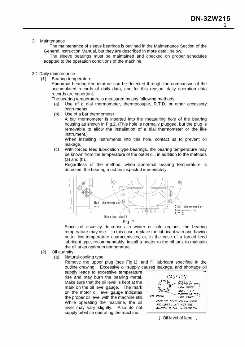
A bar thermometer is inserted into the measuring hole of the bearing housing as shown in Fig.2. (This hole is normally plugged, but the plug is removable to allow the installation of a dial thermometer or the like instrument.) When installing instruments into this hole, contact us to prevent oil leakage.
(c) With forced feed lubrication type bearings, the bearing temperature may be known from the temperature of the outlet oil, in addition to the methods (a) and (b). Regardless of the method, when abnormal bearing temperature is detected, the bearing must be inspected immediately.
Fig. 2 Since oil viscosity decreases in winter or cold regions, the bearing temperature may rise. In this case, replace the lubricant with one having better low-temperature characteristics, or, in the case of a forced feed lubricant type, recommendably, install a heater to the oil tank to maintain the oil at an optimum temperature.
(2) Oil quantity (a) Natural-cooling type
Remove the upper plug (see Fig.1), and fill lubricant specified in the outline drawing. Excessive oil supply causes leakage, and shortage oil supply leads to excessive temperature rise and may burn the bearing metal. Make sure that the oil level is kept at the mark on the oil level gauge. The mark on the motor oil level gauge indicates the proper oil level with the machine still. While operating the machine, the oil level may vary slightly. Also do not supply oil while operating the machine.
[ Oil level of label ]
Bar thermometer
Bearing shell
Dial thermometerThermocoupleR.T.D.
etc.
DN-3ZW215 6
Forced feed lubrication type Be sure to install the outlet oil piping at a down-grade of 1/30 to 1/50 in the oil return direction. Be sure to flush the piping interior and the circulation devices before starting operation. Do not flow the flushing oil into the bearing, because it contains the foreign matter that was present in the piping. (For details, refer to “Piping” in the operation manual for “Large 3-phase Induction Motor”.) Confirm that the feed oil pressure is correct with the pressure gauge, and the oil outlet flow is correct with the oil sight gauge. Maintain the oil level at the specified level because the excessive oil supply will induce leakage, and shortage oil supply will cause overheating of the bearing, as same in the case of the natural-cooling type described above.
(3) Oil ring
Check the oil ring rotation by seeing directly from the sight glass or by using the mirror.
(4) Oil leaking Check the bearing, piping and oil feeder, etc. for the absence of oil leaking.
(5) Long-term out-of-operation When the motor is left off duty for a long time, or stored as a stand-by unit, be sure to turn the rotor while supplying oil on the journal once in two weeks to prevent rusting in the journal.
3.2 Yearly maintenance
(1) Checking bearing Remove the bearing housing upper half, and check the contact pattern on the bearing metal surface for uniform contact, and check the journal for surface damage. Then, check the axial thrust surface for the absence of contact patterns.
(2) Checking oil ring Check the oil ring for abnormal side wear, for deformation and for loose joint screws.
(3) Changing lubricant Change interval of the lubricant oil is variable, depending on such conditions as the ambient temperature, ambient cleanliness level, operation condition and the severity degrees, etc. Please refer to a clause of the four chapters "lubricant" for the details.
.

DN-3ZW215 7
3.3 Maintenance and inspection at periodical overhauling The motor should be disassembled, and check all the parts at regular intervals. For the sleeve bearing, inspect it in the same way as in Section 3.2, " Yearly maintenance,", and also executes the following:
(1) Measuring bearing clearance
Measure the journal OD and bearing metal ID at several positions with a micrometer to find the bearing clearance. There is one simple way to measure clearance without taking apart the motor as follows: 1. Insert a lead wire between the journal and the bearing shell bore before removing the bearing shell lower half, and then cover the bearing sell upper half in place. 2. Clamp the bearing housing halves together. 3. The thickness of the pinched and flattened lead wire, as measured with a micrometer, is the bearing clearance. In this procedure, use a lead wire of diameter which is larger than the clearance approximately by 5/100 to 10/100 mm. Evaluate the clearance by the following equation, and if the clearance exceeds the calculated value, bearing metal must be exchanged.
(2) Measuring journal insulation resistance For those bearing which are equipped with a shaft current arrestor, measure its insulation resistance with a 500V megger. If there are measurements at least 0.5 MΩat the time of the motor disassembly shall be acceptable.
(3) Problems and Countermeasure
Bearing problems should be handled as shown in Table 2, execute the respective repair.

DN-3ZW215 8
Table 2 Bearing maintenance
Trouble, etc. Countermeasure Cleaning Thoroughly clean the oil grooves, oil outlet holes, thermometer insertion
holes, and the oil inlet/outlet for a forced feed type, with clean detergent. Finally, dry the bearing with soft and lint-free cloth, or with air blow.
Uneven contact with journal
Careful observation of the white metal surface reveals the contact pattern. When a locally concentrated contact pattern is observed, examine whether the motor coupling condition is correct, etc. and if the bearing itself is the cause, scrape off the metal from the surface area where the contact pattern is concentrated, to obtain uniform contact. In this procedure, check the contact by applying red oxide of lead thinly to the journal, and take care not to remove too much babbitt metal at once, and remove only the required minimum.
The thrust surface is partially in contact, orabnormally worn
Check whether the bearing has not been assembled in the wrong orientation, the motor itself has been leveled well, the end play is proper, or other external conditions are in order. When the cause is in the bearing itself, correct the metal surface by scraper, as above.
Eccentricity of the oil ring
Correct it by turning on a lathe.
Loosening of the oil ring joint screws
Carefully check the screw tightness at inspection. If the screw has loosen, use a screw of larger size, and re-cut the internal thread with a larger tap.
The metal surface shows minor scratches or small dents
Smooth the surface with a scraper, and when the scratches or dents are too deep, carefully remove the burr and smooth the bearing metal edges. Take care not to remove too much babbitt metal at once, and remove only the required minimum.
Electrolytic erosion isfound
Check the insulation between the bearing shell and the bearing housing, and that of the thermometer, to completely shut off the shaft current. Repair the babbitt metal surface with a scraper.
Bearing has seized orflaked
Replace the bearing metal.
Journal surface has rusted
Polish the surface with oil-soaked hemp rope using chromium oxide powder. When the rust is excessive, use an emery paper.
DN-3ZW215 9
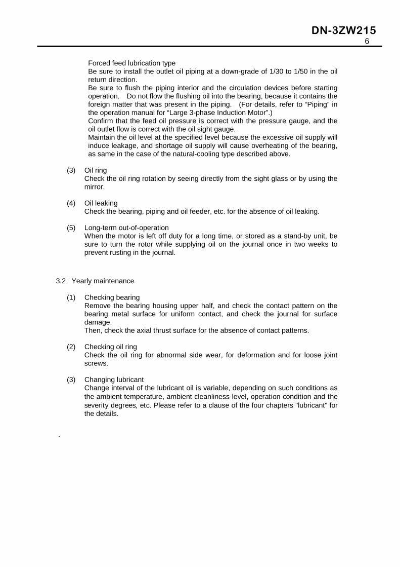
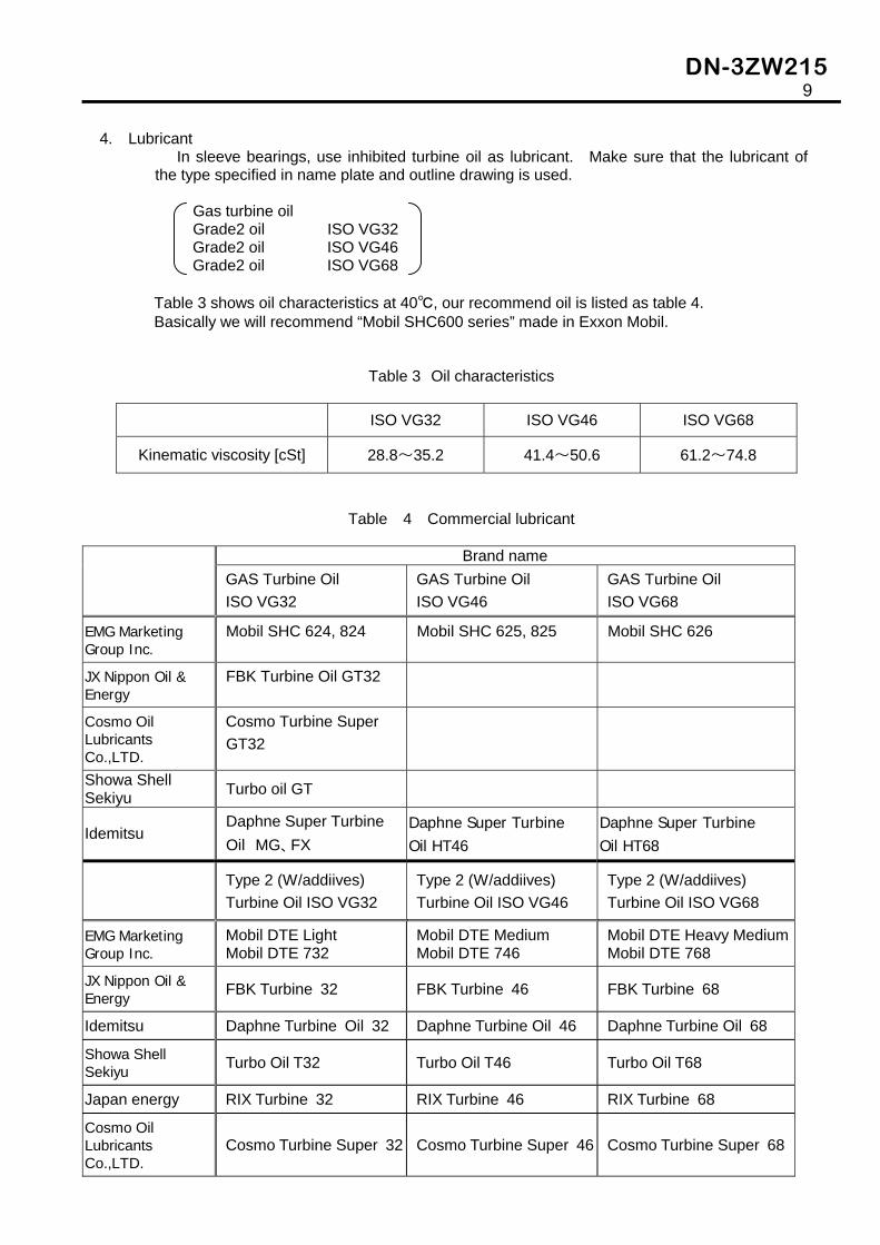
4. Lubricant In sleeve bearings, use inhibited turbine oil as lubricant. Make sure that the lubricant of
the type specified in name plate and outline drawing is used. Gas turbine oil
Grade2 oil ISO VG32 Grade2 oil ISO VG46 Grade2 oil ISO VG68
Table 3 shows oil characteristics at 40℃, our recommend oil is listed as table 4. Basically we will recommend “Mobil SHC600 series” made in Exxon Mobil.
Table 3 Oil characteristics
ISO VG32 ISO VG46 ISO VG68
Kinematic viscosity [cSt] 28.8~35.2 41.4~50.6 61.2~74.8
Table 4 Commercial lubricant Brand name
GAS Turbine Oil ISO VG32
GAS Turbine Oil ISO VG46
GAS Turbine Oil ISO VG68
EMG Marketing Group Inc.
Mobil SHC 624, 824 Mobil SHC 625, 825 Mobil SHC 626
JX Nippon Oil & Energy
FBK Turbine Oil GT32
Cosmo Oil Lubricants Co.,LTD.
Cosmo Turbine Super GT32
Showa Shell Sekiyu Turbo oil GT
Idemitsu Daphne Super Turbine Oil MG、FX
Daphne Super Turbine Oil HT46
Daphne Super Turbine Oil HT68
Type 2 (W/addiives) Turbine Oil ISO VG32
Type 2 (W/addiives) Turbine Oil ISO VG46
Type 2 (W/addiives) Turbine Oil ISO VG68
EMG Marketing Group Inc.
Mobil DTE Light Mobil DTE 732
Mobil DTE Medium Mobil DTE 746
Mobil DTE Heavy MediumMobil DTE 768
JX Nippon Oil & Energy FBK Turbine 32 FBK Turbine 46 FBK Turbine 68
Idemitsu Daphne Turbine Oil 32 Daphne Turbine Oil 46 Daphne Turbine Oil 68
Showa Shell Sekiyu Turbo Oil T32 Turbo Oil T46 Turbo Oil T68
Japan energy RIX Turbine 32 RIX Turbine 46 RIX Turbine 68
Cosmo Oil Lubricants Co.,LTD.
Cosmo Turbine Super 32 Cosmo Turbine Super 46 Cosmo Turbine Super 68
DN-3ZW215 10
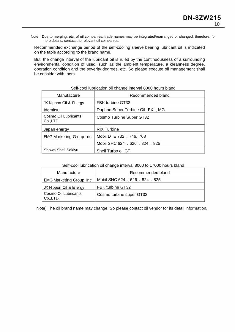
Note Due to merging, etc. of oil companies, trade names may be integrated/rearranged or changed; therefore, for more details, contact the relevant oil companies.
Recommended exchange period of the self-cooling sleeve bearing lubricant oil is indicated on the table according to the brand name.
But, the change interval of the lubricant oil is ruled by the continuousness of a surrounding environmental condition of used, such as the ambient temperature, a cleanness degree, operation condition and the severity degrees, etc. So please execute oil management shall be consider with them.
Self-cool lubrication oil change interval 8000 hours bland
Manufacture Recommended bland
JX Nippon Oil & Energy FBK turbine GT32
Idemitsu Daphne Super Turbine Oil FX 、MG Cosmo Oil Lubricants Co.,LTD.
Cosmo Turbine Super GT32
Japan energy RIX Turbine
EMG Marketing Group Inc. Mobil DTE 732 、746、768
Mobil SHC 624 、626 、824 、825 Showa Shell Sekiyu Shell Turbo oil GT
Self-cool lubrication oil change interval 8000 to 17000 hours bland
Manufacture Recommended bland
EMG Marketing Group Inc. Mobil SHC 624 、626 、824 、825
JX Nippon Oil & Energy FBK turbine GT32 Cosmo Oil Lubricants Co.,LTD.
Cosmo turbine super GT32
Note) The oil brand name may change. So please contact oil vendor for its detail information.

DN-3ZW215 11
5. Troubleshooting
Various type of trouble, their causes and countermeasures are shown in the table below.
If the trouble is considered be serious, contact us immediately.
Fault Cause Detail Actual cause Countermeasure 1. Insufficient oil
to bearing surface
(1) Faulty oil ring turning (no turning, slow turning, too quick turning)
Oil ring deformation, wear, loose joint, misaligned ends Wrong oil viscosity
Replace, if deformed by wear, or reduced weight Change oil
(2) Insufficient oil feed
Insufficient oil quantity, Oil leakage Oil circulation pump failure, Blocked oil piping Leak Excessive bearing clearance
Normal oil feeding Correct Correct
(3) Faulty bearing contact
Metal wear, Floating, Foreign matter in bearing clearance
Correct
2.Poor lubricant (1)Incorrect oil quality
Too high or too low oil viscosity Deterioration, degradation
Correct oil brand Check color and acid value
(2) Oil temperature is too high
Too high room temperature, poor oil cooling
Check cooling water system
(3) Foreign matter in oil
Water, solid (dust, metal powder)
Study contamination route
3. Faulty bearingcooling (Directcooling system)
(1)Faulty cooling water system
Pipe system, valve blocked or leaking Faulty pump
Check cooling water system
4. Shaft current (1) Faulty bearing insulation
Contamination, water, wet by oil, faulty piping insulation
Clean and check insulation resistance
5. External cause (1) Excessive vibration
Direct coupling misalignment, shaft bending, installation misalignment
Correct alignment
Bearing seizure
(2) Abnormal thrust
Impact from machine Check load machine
Excessive heating of bearing
Pre-symptom of bearing seizure Identical cause
Keep records of normal bearing temperature, pay attention to slight temperature rise, and stop operation when temperature rise sharply, and check.

DN-3ZW215 12
6. Disassembly and reassembly of sleeve bearings
The disassembling and reassembling procedures of horizontal, bracket type bearings may vary slightly according to the motor types, but typically they are executed as described below:
6.1 Preparation for disassembly
(1) Thoroughly study the structure of the machine to be disassembled. Make preparation for the disassembly procedure. Prepare disassembly tools.
(2) Carefully select the area for disassembly. Avoid dusty areas. Be careful of the weather when disassembling outdoor machines, and if
necessary, bring them indoors.
(3) Carefully clean the area around the bearing, Including the shaft and the bearing housing.
6.2 Bearing disassembly procedure
6.2.1 Removing accessories
(1) Remove the dial thermometer, thermocouple or other bearing temperature measuring devices.
(2) Drain the lubricant from the bearing housing through the drain port by removing the plug.
(3) Disconnect the oil feed pipe, if connected.
6.2.2 Removing bearing housing upper half (see Fig. 3, Fig. 4)
(1) Remove clamping bolts ③ for bearing housing upper half ① and bearing upper half cover ②, and take off upper half cover ②.
(2) Remove clamping bolts ⑤ for bearing housing upper half ① and bearing housing lower half ④.
(3) Lift the bearing housing upper half ① carefully and slowly, taking care to avoid fouling other components, and remove it. Especially, to prevent damage to the floating seals during disassembly, when lifting the bearing housing upper half ①, keep the bottom surface horizontal at all times. Note that the opposite load side bearing is normally provided with an insulator to prevent shaft current: Pay attention to it during disassembly and reassembly. In addition, take care to keep this area free from contamination by foreign matter that may allow current at all times.

DN-3ZW215 13
Fig. 3
Fig. 4 Fig. 5
Wire rope
1
4
Drain plug
Eye-bolt
4
6
Oil ring
(Bolts)
Upper plug (oil filler)
(Bearing housing upper half)
(Bearing housing lower half)
Bearing shell
Floating seal
(Upper half cover)
(Bolts)

DN-3ZW215 14
6.2.3 Disassembly of bearing shell upper half (see Fig. 5)
(1) Screw eye-bolts into bearing shell upper half ⑥.
(2) Pass wire rope through the eye-bolts and lift the bearing shell upper half vertically. Take care not to damage the metal while removing the bearing shell, and be sure to place the removed bearing shell on protective wood blocks, not directly on the floor.
(3) Move the bearing shell slowly, and absolutely avoid crash drop.
6.2.4 Disassembly of oil ring (see Fig. 6)
(1) Rotating the joint to the top, and then remove the joining screws from oil ring ⑦.
(2) Take out oil ring ⑦ from the journal.
Fig. 6
6.2.5 Disassembly of floating seal (see Fig. 7)
(1) Unlock garter spring ⑨, and take out upper half ⑩ of floating seal.
(2) Rotate floating seal lower half ⑪to the top position, and remove it. When taking out the floating seals, pay attention to prevent damage.
Fig. 7
6.2.6 Disassembly of bearing shell lower half (see Fig. 8, 9, 10) Synchronize the disassembly procedures on the two sides, the load side and the
opposite load side.
7 7
4 8
“A”“A”9
10 11

DN-3ZW215 15
(1) Lift up the rotor within the limit that can remove bearing shell lower half ⑧. In this procedures, take care to avoid the contact of the air gap between the rotor and the stator. The allowable lifting limit is 0.5 mm. Example of rotor lifting method. i) Jacking up the load side coupling. ii) Lift the shaft end of the opposite load side with a fine-adjustable chain
block, applying wire rope to the shaft end over a protection sheet.
Fig. 8
As the other method, there is the case that the opposite load side also be jacked up as shown in i), or when the shaft is not extended, there is the case that a pipe is inserted into the shaft end and this pipe is lifted with a wire rope (see Fig. 9).
iii) This work must be executed with utmost care and attention, and must be
entrusted by skilled workers.
(2) During lifting the rotor, rotate bearing shell lower half ⑧ to the top position of the shaft journal.
(3) Screw eye-bolts into bearing shell lower half ⑧, and take it out by lifting (see Fig. 10). Take utmost care in this procedure as same in the case of the bearing shell upper half.
Dial gauge Coupling
Wood block
Jack
Dial gauge
Chain block
Wire rope
Protection
8
Sheet

DN-3ZW215 16
Fig. 9 Fig. 10
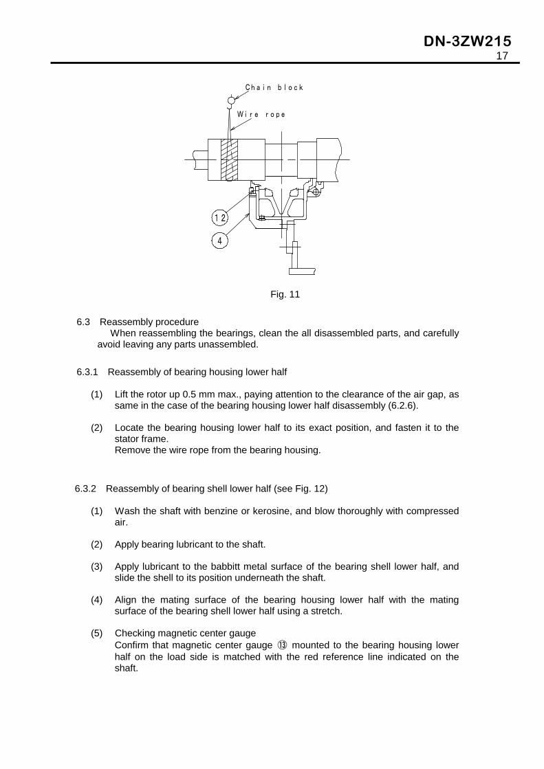
6.2.7 Disassembly of bearing housing lower half (see Fig. 11) The bearing housing lower half is disassembled only when the rotor is pulled out.
(1) Remove the fastening bolts for seal carrier ⑫ on the load side and on the
opposite load side.
(2) Set up eye-bolts into the screw holes of the lower half fastening the upper half and the lower half of the bearing housing, and hold the bearing housing by passing wire rope through the eyes, paying attention to the center of gravity location.
(3) Remove the bolts that are fastening the housing lower half to the stator frame.
(4) Lower or remove the bearing housing lower half not to prevent the rotor pulling-out. In general, since the rotor is pulled out to the opposite load side, lower the bearing housing lower half on the load side only enough to clear the coupling (the coupling flange outer diameter must be smaller than the stator core bore), and remove the bearing housing lower half on the opposite side to prevent damage to the collector, etc.
(5) Carefully lower the rotor by loosening the jack and the wire rope, and place the rotor on the stator core. In this procedure, lower the jack and the wire rope on both the load side and the opposite side simultaneously so as to avoid partial contact and impact to the core surface.
Dial gauge
Chain block
Wire rope
8
Pipe
4
Dial gauge
Chain block
Wire rope
8
4
DN-3ZW215 17
Fig. 11
6.3 Reassembly procedure When reassembling the bearings, clean the all disassembled parts, and carefully
avoid leaving any parts unassembled.
6.3.1 Reassembly of bearing housing lower half
(1) Lift the rotor up 0.5 mm max., paying attention to the clearance of the air gap, as same in the case of the bearing housing lower half disassembly (6.2.6).
(2) Locate the bearing housing lower half to its exact position, and fasten it to the stator frame. Remove the wire rope from the bearing housing.
6.3.2 Reassembly of bearing shell lower half (see Fig. 12)
(1) Wash the shaft with benzine or kerosine, and blow thoroughly with compressed air.
(2) Apply bearing lubricant to the shaft.
(3) Apply lubricant to the babbitt metal surface of the bearing shell lower half, and slide the shell to its position underneath the shaft.
(4) Align the mating surface of the bearing housing lower half with the mating surface of the bearing shell lower half using a stretch.
(5) Checking magnetic center gauge Confirm that magnetic center gauge ⑬ mounted to the bearing housing lower half on the load side is matched with the red reference line indicated on the shaft.
4
Chain block
Wire rope
12

DN-3ZW215 18
(6) Carefully lower the floating rotor and support it by the bearing shell lower half.
(7) Install the seal carrier that have been removed in 6.2.7, and make sure that their clearance with the shaft is correct by measuring with a thickness gauge.
Fig. 12
6.3.3 Reassembly of oil ring Reassemble the two halves of the oil ring carefully avoiding wrong pairing. If
wrong halves are assembled together, they don’t fit well or may be elliptic, resulting in improper rotation.
The joint of the rings should be within the surface of the ring sides.
6.3.4 Reassembly of bearing shell upper half
(1) Screw eye-bolts into the bearing shell upper halves, and slinging them vertically with wire rope, reassemble them with the bearing shell lower halves. Align the match marks on the upper and lower bearing shell halves.
(2) Thoroughly check that all the parts such as the anti-rotation pin are assembled in the bearing housing.
(3) Check that not foreign objects such as tools and bolts are left in the bearing housing.
(4) Be sure to apply oil seal to the mating surfaces of the housing to prevent oil leakage.
6.3.5 Reassembly of floating seal
(1) Apply un-hardening compound or grease thinly on the peripheral side faces (“A” in Fig. 7) of the floating seal, and apply lubrication oil thinly on the bore of the floating seal.
(2) Insert the floating seal lower half (with a oil drain hole) into the seal carrier and lower half by turning it. Make sure that the drain hole is facing inside the oil sump.
Red reference line
8 13
DN-3ZW215 19
(3) Install the floating seal upper half. Wound the garter spring around the floating seal, and lock it. Carefully align the upper and the lower halves of the floating seal to make their surfaces flush. After assembling, make sure it is free from jamming to be caused from deformation by turning it.
(4) During reassembling the seal carrier upper half, confirm that the anti-rotation pin of the seal is properly secured in its groove.
6.3.6 Reassembly of bearing housing upper half
(1) Reassemble the bearing housing upper half by the reversing procedure as shown in 6.2.2.
(2) Install the dial thermometer, thermocouple or other bearing thermometer.
(3) With a forced lubrication type bearing, reassemble the oil inlet and outlet piping. Fill lubricant up to the level indicated on the oil level gauge.
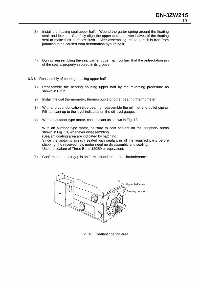
(4) With an outdoor type motor, coat sealant as shown in Fig. 13.
With an outdoor type motor, be sure to coat sealant on the periphery areas shown in Fig. 13, whenever disassembling. (Sealant coating area are indicated by hatching.) Since the motor is already sealed with sealant in all the required parts before shipping, the received new motor need no disassembly and sealing. Use the sealant of Three Bond 1208D or equivalent.
(5) Confirm that the air gap is uniform around the entire circumference.
Fig. 13 Sealant coating area
Upper half cover
Bearing housing

DN-3ZW215B TM124B(201309)