DMRB VOLUME 6 SECTION 2 PART 8 - Standards for … · of large traffic signal junctions. ... layout...
46
February 2003 DESIGN MANUAL FOR ROADS AND BRIDGES VOLUME 6 ROAD GEOMETRY SECTION 2 JUNCTIONS PART 8 TA 86/03 LAYOUT OF LARGE SIGNAL CONTROLLED JUNCTIONS SUMMARY This Advice Note gives recommendations for the procedures for designing and assessing the performance of large traffic signal junctions. It is intended to supplement and be used in conjunction with TD 50 (DMRB 6.2.3). The Design Standard for The Geometric Layout of Signal Controlled Junctions and Signalised Roundabouts. INSTRUCTIONS FOR USE This is a new Advice Note to be incorporated in the Manual. 1. Insert TA 86/03 into Volume 6, Section 2, Part 8. 2. Please archive this sheet as appropriate. Note: A quarterly index with a full set of Volume Contents Pages is available separately from The Stationery Office Ltd.
Transcript of DMRB VOLUME 6 SECTION 2 PART 8 - Standards for … · of large traffic signal junctions. ... layout...

February 2003
DESIGN MANUAL FOR ROADS AND BRIDGES
VOLUME 6 ROAD GEOMETRYSECTION 2 JUNCTIONS
PART 8
TA 86/03
LAYOUT OF LARGE SIGNALCONTROLLED JUNCTIONS
SUMMARY
This Advice Note gives recommendations for theprocedures for designing and assessing the performanceof large traffic signal junctions. It is intended tosupplement and be used in conjunction with TD 50(DMRB 6.2.3). The Design Standard for TheGeometric Layout of Signal Controlled Junctions andSignalised Roundabouts.
INSTRUCTIONS FOR USE
This is a new Advice Note to be incorporated in theManual.
1. Insert TA 86/03 into Volume 6, Section 2, Part 8.
2. Please archive this sheet as appropriate.
Note: A quarterly index with a full set of VolumeContents Pages is available separately from TheStationery Office Ltd.

TA 86/03
Layout of Large SignalControlled Junctions
Summary: This Advice Note gives recommendations for the procedures for designing andassessing the performance of large traffic signal junctions. It is intended tosupplement and be used in conjunction with TD 50 (DMRB 6.2.3). The DesignStandard for The Geometric Layout of Signal Controlled Junctions andSignalised Roundabouts.
DESIGN MANUAL FOR ROADS AND BRIDGES
THE HIGHWAYS AGENCY
SCOTTISH EXECUTIVE DEVELOPMENT DEPARTMENT
WELSH ASSEMBLY GOVERNMENTLLYWODRAETH CYNULLIAD CYMRU
THE DEPARTMENT FOR REGIONAL DEVELOPMENTNORTHERN IRELAND

Volume 6 Section 2Part 8 TA 86/03
February 2003
REGISTRATION OF AMENDMENTS
Amend Page No Signature & Date of Amend Page No Signature & Date ofNo incorporation of No incorporation of
amendments amendments
Registration of Amendments

Volume 6 Section 2Part 8 TA 86/03
February 2003
REGISTRATION OF AMENDMENTS
Amend Page No Signature & Date of Amend Page No Signature & Date ofNo incorporation of No incorporation of
amendments amendments
Registration of Amendments

VOLUME 6 ROAD GEOMETRYSECTION 2 JUNCTIONS
PART 8
TA 86/03
LAYOUT OF LARGE SIGNALCONTROLLED JUNCTIONS
Contents
Chapter
1. Introduction
2. Design Procedure
3. Junction Types
4. Preliminary Design and Testing
5. References
6. Enquiries
Annexes
Annex A Relative Junction Performance
Annex B Traffic Flow Groups Used for CapacityTests
Annex C Compound Signal Controlled Junctions
Annex D Definitions
DESIGN MANUAL FOR ROADS AND BRIDGES
February 2003

Volume 6 Section 2Part 8 TA 86/03
Chapter 1Introduction
1. INTRODUCTION
General
1.1 Standard TD 50 (DMRB 6.2.3) sets out theOverseeing Department’s design standards,methodology and good design practice for thegeometric layout of signal controlled junctions. TheStandard highlights design considerations for thedevelopment of site specific final designs. CurrentHighway Design Standards and Technical Advice Notesin the Design Manual for Roads and Bridges shall beused in the design of large traffic signal controlledjunctions. Standards cover the relevant safety aspects ofHighway Design. Advice Notes give guidance on bestpractice an efficient and effective design which theiruse will ensure that safety issues are considered in thedesign.
1.2 The Highways Agency Code of PracticeConsultancy (Dec 1997) or (Overseeing Organisation’sequivalent) recommends and makes reference to goodpractice to be adopted for all traffic control orinformation systems from design and installation,through to the operation and de-commissioning of thesystem. The Code of Practice promotes safety andeffectiveness through good practice and procedures andforms a central reference, guiding users to otherrelevant DETR publications that contain advice on thedesign, maintenance and operation of systems.
1.3 The purpose of this Advice Note is to supplementTD 50 (DMRB 6.2.3), The Code of Practice andprovide guidance to the Highway Engineer on theprinciples that steer the design of large signal controlledjunctions on Trunk Roads. It gives examples of newtypes of signal control at junctions where additionalcapacity is required and shows in what circumstancesthey can be used. The analytical methods for assessingthe operational characteristics of signalised junctionsare described together with suggestions as to thedifferent types of computer simulation softwarecurrently available.
1.4 Definitions of the principal technical terms usedin this document in relation to signal controlledjunction design can be found in Annex D and Annex 1of TD 50 (DMRB 6.2.3). Publications giving furtherdetailed information on the subject are listed inChapter 6.
February 2003
1.5 As traffic densities increase, junctions arerequired to handle ever-growing volumes of vehicles.Economic and environmental constraints will oftenpreclude the option of grade separating major trafficflows at junctions and in these situations, at-gradesolutions with junctions designed specifically for trafficsignal control can sometimes provide cost-effectiveoptions and maximise the capacity of the junctions.
1.6 In view of the cost of the highway worksassociated with a large signal controlled junction,proper design and assessment of the geometric optionsis essential to determine the most efficient layout forthe particular traffic conditions.
Scope
1.7 This Advice Note considers the issues governingthe design of large signal controlled junctions andincludes the design of new junctions and existingjunctions converted to signal control. It gives anoverview of the types of large signal controlledjunctions used in practice and comments on thecircumstances in which these types of junction maywork most successfully.
1.8 This document is intended to offer advice on thelayout of large signal controlled junctions on trunkroads in urban and rural locations. Junctions in theselocations will require different design considerationswhen taking into account the provision for non-motorised road users.
1.9 Large signal controlled junctions may vary intype from complex single node junctions where thedesign of the signal phase and stage structure willgreatly influence capacity, to multi-node junctionswhere each node has a simple signal phase and stagestructure and where the design of good signal co-ordination between nodes will be the more importantissue. Although the principal concern of the evaluationof the type of junction to be considered may be tocreate additional capacity for vehicles, the needs ofpedestrians and cyclists should not be suppressed. Theresulting solution should aim to improve conditions forall road users.
1/1

Volume 6 Section 2Part 8 TA 86/03
Chapter 1Introduction
1.10 Where example layouts of junctions arepresented in this Advice Note, these are of adiagrammatic nature and are intended for guidanceonly.
Implementation
1.11 This Advice Note should be used forthwith on allschemes for the management, improvement andmaintenance of Trunk Roads currently being preparedprovided that, in the opinion of the OverseeingOrganisation, this would not result in significantadditional expense or delay progress. DesignOrganisations should confirm its application toparticular schemes with the Overseeing Organisation.
February 20031/2

Volume 6 Section 2Part 8 TA 86/03
Chapter 2Design Procedure
2. DESIGN PROCEDURE
General
2.1 The geometric form of a large traffic signaljunction will be determined by the nature of theindividual circumstances. A recommended process bywhich the final solution may be achieved is described inFigure 2/1.
Note: A similar diagram is shown in the Highways Agency Code of Practice (Figure 2/9)
Figure 2/1: Typical Design Process
Select junction typefor testing
Junction types
Revise control
strategy & modify /
optimise design
(cost / benefits of
optimisation)
Test junction performance
Can junction performance
be improved?
No
Have alternativejunction options
been tested?
Yes
Yes
No
Safety
Life Cycle Costing
Environmental Impact
Value/Risk Workshop
Cost Benefit
DETAILED DESIGN
BRIEF
As required by the overseeing
Organisation.
Assessment of Operational PerformanceFurther Assessments
Appraisal Summary
CapacityCongestion
CostDevelopment
proposals
Accident dataTopography
Relevant Considerations Future YearCurrent Year
Traffic Growth
Demand management
Planning dataInduced traffic
Committed transport system
changes
Identify & quantify problems, constraints and opportunities
Queue and delayJourney time
Public transport
Geotecnical & topographical
Services
AccidentsVulnerable road users
Traffic data including pedestrians and cyclists
Origin / Destination
February 2003 2/1

Volume 6 Section 2Part 8 TA 86/03
Chapter 2Design Procedure
2.2 This process can be grouped into three stages(see Figure 2/1):
• the data gathering stage (RelevantConsiderations, Current and Future year);
• the preliminary design and testing stage (FurtherAssessment, Assessment of the OperationalPerformance and Appraisal Summary);
• the detail design stage (Detailed Design Brief).
2.3 The detail design stage does not form part of thisAdvice Note. Matters relating to the detail design ofjunction and carriageway construction are addressed inthe relevant Technical Standards and Advice Notes inthe DMRB.
Data Gathering (see Figure 2/1)
2.4 This is the initial stage of the design processwhere information relevant to the design of the junctionis gathered and collated.
2.5 From this information it will be possible toestablish the basic constraints on the design of thejunction and the traffic flows which are likely to use itin the design year.
2.6 Information is likely to be required in thefollowing areas:
• existing traffic conditions (this should cover allvehicle types);
• pedestrian and cycle, movements and desirelines, and any local land uses which may requireindividual measures, eg school, hospital;
• current and future traffic flows;
• existing accident patterns;
• approved and potential development proposalswithin the design period;
• Local Plan policies relating to future land use;
• Local Transport Plan policies relating topedestrian, cycle, equestrian, public transport andprivate transport routes;
• Land availability with an accurate survey of theproposed site at a scale of not less than 1:500.
2/2
2.7 This information will help to define the nature ofthe problem and how existing and future planningpolicies and proposals may influence traffic patterns.
2.8 Classified traffic flow data (including non-motorised users) will be an important element in thedesign process. In the case of an existing junction thiswill require both counts of actual traffic movements,including pedestrians, and an assessment of any futuredevelopments likely to affect the traffic movementsthrough the junction.
Preliminary design and testing (see Figure 2/1)
2.9 During this stage the preliminary designs will beprepared, tested and optimised. It is likely that morethan one design will fulfil the design criteria and someform of economic appraisal of the final options may benecessary.
2.10 Some basic junction configurations areconsidered in Chapter 3 and the relative performance ofthese configurations, together with a suggestedselection process, is discussed in Annex A. This isintended as an aid in the initial selection of geometricoptions.
2.11 The process will comprise the formulation ofefficient control strategies and the necessary highwaygeometry to enable the control strategies to beeffectively implemented.
2.12 There will be an iterative process of design,testing and optimisation. The final design may wellcontain features from more than one junctionconfiguration and ideally several options should beassessed to ensure the best solution is achieved. Thisexercise will form the majority of the work undertakenin developing a solution and is discussed more fully inChapter 4 and Annex A.
2.13 The process will be aided by the use of computersoftware packages. These packages will either take theform of conventional modelling which use establishedequations to predict reserve capacity, delays andqueues, or micro simulation. This technique hasrecently been used to predict the operation of junctionsand networks on a microscopic level.
2.14 A micro simulation explicitly models theinteraction of vehicles, junction geometry and signalcontrol. It enables a number of design features such asblocking, flaring, merging and lane switching to bemodelled more accurately than conventional computermodels. However, whether these effects are critical in a
February 2003

Volume 6 Section 2Part 8 TA 86/03
Chapter 2Design Procedure
particular design depends on the junction type,geometric features, signal control and traffic flows.
2.15 A micro simulation model will usually requiremore resources and take longer to build and calibratethan a conventional model. For this reason a microsimulation model should only be considered where theaccuracy of modelling could be improved by these extraresources; for example where a number of the designfeatures mentioned above are likely to cause a problem.However, even when the need to build a microsimulation model is identified, a conventional modelshould still be used for preliminary design. This is toavoid the increased resources of simulation modellingat an early stage in a project and to identify areas of thedesign where greater detail will be required in thesimulation.
February 2003 2/3

Volume 6 Section 2Part 8 TA 86/03
Chapter 3Junction Types
3. JUNCTION TYPES
General Information and Advice
3.1 Large signal controlled junctions can be groupedinto two broad categories:
• complex single node junctions, such ascrossroads, where conflicts occur at a singlepoint or node;
• multi-node junctions, such as roundabouts andgyratory systems, where conflicts are separated,and occur at a series of nodes arranged into abroadly circular pattern.
These are fundamental concepts that need to beconsidered at an early stage in the design process.
3.2 At a single node junction all conflicts occur at asingle point. Where right turns are separately signalled,there are generally four vehicle conflict groups eachrequiring its own part of the signal cycle time.
3.3 In principle this is a simple method of junctioncontrol but the number of intergreen periods required tohandle the various conflicts can result in a significantproportion of lost time during each cycle and the needfor long cycle times.
3.4 The optimum capacity of single node junctionswill be achieved with a layout and signal control systemthat enables as many non-conflicting traffic movementsas possible to occur at the same time during the cycle.There may be several ways in which this can beaccomplished and the traffic flows through the junctionwill be the prime indicator of which of the possiblearrangements are likely to be the most efficient.
3.5 At multi-node junctions the aim is to improve onthe single node described above with a series of nodes,each with two conflicting traffic movements. Thereduction in conflicts will reduce the lost timeassociated with a single node. The performance of thistype of junction is dependent on the co-ordination ofthe signal settings between the separate nodes.Considerable effort will be required to establish the bestco-ordination.
February 2003
Entry Arms and Circulatory Carriageways
3.6 Large signal controlled junctions are ofteninnovative in design and provide at-grade solutions toproblems associated with providing vehicular capacityin a restricted environment. The number of lanesprovided on the approach to and within a circulatorycarriageway is dependent on the volume of traffic, theexit distribution of traffic and space availability. Thelayout of the signalised nodes should conform to therequirements set out in TD 50 (DMRB 6.2.3). In thecase where a node is not signalised then the layoutshould conform to the appropriate standard.
3.7 Generally for layouts with four or fewer lanes ata stopline the design principles in TD 50 (DMRB6.2.3) can be accomplished. Driver uncertainty canaffect capacity, control and safe operation of thejunction. Therefore layouts with five or more lanes at astopline are not recommended, because of the problemscaused by the complexity of design issues such as:
• visibility of signal heads;
• vertical signing;
• lane designation and marking; and
• provision for non-motorised users.
3.8 These elements and types of junction aredescribed more fully below and their relativeperformance is discussed in Annex A.
Designated Lanes
3.9 Designated lanes are marked out on theapproaches, exits and circulatory carriageway ofjunctions. They can be designated for use by:
• buses (see TD 50 (DMRB 6.2.3));
• large goods vehicles (LGVs);
• taxis and high occupancy vehicles;
• cycles (see TD 50 (DMRB 6.2.3)).
3/1
Volume 6 Section 2Part 8 TA 86/03
Chapter 3Junction Types
3.10 Designated lanes are often generically referred toas ‘bus lanes’ although in practice other vehicle types,in addition to buses, could use the lanes.
3.11 Providing designated lanes at junctions can resultin an overall reduction in junction capacity for vehiclesbut an increased capacity for the movement of people.It may be possible to modify an existing junction byincorporating traffic signal control that maintains thecapacity for existing road users and can enhance thefacilities for traffic using the designated lanes.
3.12 Further information on the provision ofdesignated lanes can be found in the Institution ofHighways and Transportation publications ‘Transport InThe Urban Environment’ (1997) and ‘Guidelines ForPlanning For Public Transport In Developments’(1999).
3.13 Improved facilities for traffic using thedesignated lanes can be provided in several ways:
• using traffic signal control to provide additionalcapacity to cater for all movements on arelatively short cycle time, then delays toprioritised traffic will be minimal;
• by providing specific lanes or segregated signals;
• in a passive way by detection to hurry call orhold specific signal stages;
• by providing a signal at a stop line in advance ofthe main junction that would be co-ordinatedwith the main stop line. These advance signalswould allow the reservoir between the advancesignals and the main stop line to be relativelyclear of queuing traffic during the red phase,allowing prioritised traffic easy access into anylane;
• by introducing turning exemption or segregatedbypass lanes, which allows prioritised traffic tomake a movement that is prohibited to othertraffic.
Bus Lanes
3.14 When assessing the need for facilities to aidpublic transport, bus priority should be consideredwhere buses would be delayed by queuing traffic orwhere buses would have difficulty in making aparticular movement, eg where lane switching isrequired. Bypassing queuing traffic is possible by theprovision of a bus lane but complications arise at the
3/2
junction itself. If segregated bus signalling is to beavoided, then the bus lane will need to utilise the samesignal phase as the other traffic. In order to cater for leftturning traffic, the dedicated bus lane will have to bestopped short, to allow left turners into the nearsidelane.
3.15 If additional stop line capacity is required, thenthe bus lane may need to be terminated further backfrom the stop line and the capacity of the approachcalculated on the basis that the approach is ‘flared’. Tocater for buses that want to make a right turn and needto manoeuvre across normal traffic lanes a special busphase could be provided, however, at some junctionsthis could restrict capacity and could affect other busroutes.
Guided Buses, Trams and Light Rapid Transport(LRT) Systems
3.16 A number of cities have introduced fixed tracksystems to enhance public transport. Most track systemswill have a proportion of segregated track. Where thereis an element of street running, signal priority measuresare required to minimise delays and allow reliablejourney times.
3.17 Vehicles running on fixed track systems requirespecial consideration when incorporating them intolarge signalised junctions. Particular attention should begiven to the swept vehicle path, stopping distances, theneed for stops and frontage servicing.
Cycle Lanes/Cycle Tracks
3.18 The traffic signal control of the single nodejunction itself represents an improvement of roadconditions for cyclists in comparison with a priority-controlled junction.
3.19 The provision of cycle facilities on thecarriageway is addressed in the Traffic Advisory Leafletseries, TD 50 (DMRB 6.2.3), TA 67 (DMRB 5.2.4),Cycle-Friendly Infrastructure Guidelines for Planningand Design (1996) and The National Cycle NetworkGuidelines and Practical Details (1997). See referencesin Chapter 5. Various techniques are used nationally tocreate crossing facilities with local variations inpractice. It is recommended that an examination ismade of local practices and a liaison established withthe relevant department of the Local Authority at anearly stage in the design procedure.
February 2003

Volume 6 Section 2Part 8 TA 86/03
Chapter 3Junction Types
Facilities for Pedestrians and Cyclists
3.20 Correctly located crossings are critical to walkingand cycling activities and can help overcome severancecreated by busy roads. A balance needs to be struckbetween the legitimate needs of all road users. Thisbalance will be influenced by the location of thejunction and the volume of pedestrian and cycle traffic.In an urban situation, at-grade facilities may be moreappropriate. The location of at-grade cycle or pedestriancrossings, whether controlled or uncontrolled, at sliproads of grade-separated intersections should beavoided wherever possible, particularly where approachspeeds are likely to be in excess of 40mph. Thecrossings should be positioned away from locationswhere drivers might be applying maximum accelerationTA 67 (DMRB 5.2.4). In such circumstancessegregated facilities may be more appropriate.
3.21 From a pedestrian perspective an ideal crossingfacility would be safe, coincide with desire lines, allowfor crossing the junction in all directions, providesufficient space to accommodate pedestrian capacityand provide adequate opportunity for traversing thejunction with quick response to demand.
3.22 A list of Traffic Advisory Leaflets and LocalTransport Notes relating to pedestrian and cyclefacilities can be seen in Chapter 5.
At-Grade Facilities for Pedestrians and Cyclists
3.23 Pedestrian and cycle flows should initially beconsidered as two different movements. If theirindividual requirements turn out to be similar, thenconsideration should be given to providing jointfacilities such as Toucan crossings. The shared use ofspace by pedestrians and cyclists should only beconsidered as a last resort when all other solutions havebeen dismissed. Unsegregated shared use should beavoided, particularly in heavily used urban contexts.
3.24 Pedestrian facilities are sometimes provided bystopping all traffic movements and introducing a“pedestrian stage” during which pedestrians can crossall arms of the junction. The disadvantage of thismethod is that the pedestrian stage results inconsiderable lost time which seriously degrades thecapacity of the junction and forces the use of longsignal cycle times. This in turn means that pedestrianwaiting times are long with the corresponding increasedrisk of pedestrians crossing against the “red man”signal.
3suncaaprean
3farerepin
3pexpdwaf
GC
3pracoinexhcoscFmg
3mindpnwitfofecanin
February 2003
.25 The pedestrian facilities can often be designed inch a way that the pedestrian is able to cross when
on-conflicting streams of traffic are running. In thisse a specific signal would indicate when it ispropriate for the pedestrian to cross. These areferred to as “walk-with-traffic” pedestrian facilitiesd are in described in TA 15 (DMRB 8.1.1).
.26 The provision of walk-with-traffic pedestriancilities separates pedestrian routes into a series oflatively short sections between safe refuges. As asult shorter green man periods are required at the
oints of conflict and the pedestrian-to-traffictergreen periods are shorter.
.27 Walk with traffic pedestrian facilities require therovision of a pedestrian/cycle facility on a junctionit which is not at a natural stop line (an entry does
rovide a natural stop line). These facilities can beesigned as self-contained crossings but co-ordinatedith the main junction. However, they may adverselyfect the vehicular capacity of the junction.
rade-Separated Facilities for Pedestrians andyclists
.28 The provision of grade-separated facilities foredestrian or cycle movements should be based on ange of factors. These include pedestrian flows andmposition, the type and width of the proposedfrastructure to cross the junction, levels and gradients,posure of pedestrians and cyclists to hazards such as
igh winds, adverse weather conditions and noise,nstruction and maintenance costs, and finally, theope for combining cyclist and pedestrian movements.
or segregated facilities to be attractive to users theyust be safe and secure. This is achieved by providing
ood visibility to the user’s destination.
.29 Consideration should be given to cyclists whoay not use grade-separation if it involves steepclines. Therefore, to protect cyclists from potentially
angerous sections of the junction they should berovided with attractive routes that are easy toegotiate. These may not necessarily involve dual useith pedestrians. Each location needs to be assessed ons individual merits; the current and forecast demandr a grade-separated facility and the acceptability/asibility of the facility. Successful grade-separationn be achieved if the facilities are provided along
atural desire lines and routes are short with minimalcline.
3/3

Volume 6 Section 2Part 8 TA 86/03
Chapter 3Junction Types
Single Node Crossroads
C
B
D
A
Figure 3/1: Single Node Crossroads
February 20033/4

Volume 6 Section 2Part 8 TA 86/03
Chapter 3Junction Types
3.30 This is a common form of complex signalcontrolled junction. All traffic movements haveassigned traffic lanes and are positively controlled at asingle node or point of conflict. The number of trafficlanes and the length of flares at the stop line aredictated by the requirements of the traffic flows throughthe junction. Drivers understand this type of junction
Sig-nabout
February 2003
and there are no requirements for internal signal co-ordination.
3.31 Because all the conflicts take place at a singlepoint the capacity of the junction is dependent on bothgeometry and a signal sequence that minimises lost timein the signal cycle.
Figure 3/2: Sig-nabout
D
CA
B
3/5
Volume 6 Section 2Part 8 TA 86/03
Chapter 3Junction Types
3.32 The geometry of the junction is similar to thesingle node crossroads with three essential differences:
• the flares on the approach arms are wide butshort to provide relatively high capacity withshort cycle times;
• an element of deflection for the aheadmovements through the junction is incorporatedin the geometry, thus helping to reduce trafficspeed;
• carriageway markings in the central area (ornode) of the junction are used to position anddirect right turning traffic;
• right turning vehicles are generally not positivelycontrolled but can accept gaps in opposing trafficmovements and make use of intergreen times tonegotiate the junction. There is however somepotential for separate control of a dominant rightturn.
3.33 The aim of the signal sequence is to control thefour conflict groups in two stages rather than the fourthat are required with fully signalled right turns. This isachieved by clearing right turning vehicles in the morefrequent intergreen periods resulting from a short cycletime.
3.34 A short cycle time is used so that the flaredapproaches contribute their maximum effect. Theresulting increase in lost time is offset by the right turnmovements taking place during the intergreen periods.The right turning traffic is not positively controlled andcan accept gaps in the opposing traffic flow in theperiod preceding the intergreen.
3.35 A short cycle time is also necessary to achievesufficient capacity for right turning traffic and two rightturn lanes are used to store the right turning vehicles inthe centre of the junction. The short cycle time providesa sufficient number of intergreen periods toaccommodate the demand for the right turn.
3.36 The layout of the junction provides right turningvehicles with a segregated stop line. Because a rightturning motorist would normally associate a segregatedstop line with a fully signalled right turn manoeuvre, itis necessary to consider appropriate signing toemphasise the opposed nature of the turn.
3/6
3.37 Walk-with-traffic pedestrian facilities can beprovided across the entry arms in a similar manner tothe single node crossroads. However, the unique controlstrategy of the junction means that similar pedestrianfacilities cannot be provided across the exit lanes andexit Pelican or Puffin Crossings might be necessary.These facilities may be remote from the junction butlinked to the junction control system.
3.38 This form of junction is not as beneficial to thecyclist as the single node crossroads due to the opposednature of the right turn movements. It is recommendedthat if special provision for cyclists is required then thisshould be segregated if possible. This may be by avariety of means depending on the volume of cycletraffic, desire lines and the ability to segregate thecrossing vertically or horizontally away from theconflict point of the junction without unduly affectingthe convenience of the cyclists.
Signalised Roundabouts
3.39 A signalised roundabout operates differentlyfrom a normal roundabout (see definition of ‘normalroundabout’ in TD 16 (DMRB 6.2.3). Traffic signalscontrol driver behaviour by dictating how a vehicleproceeds through the junction. The controlledplatooning of traffic around and through a junction hasthe effect of limiting vehicle speeds, improving lanediscipline and reducing the need for weaving. Theguidance for the geometric design standards forsignalised roundabouts that are full, partially or part-time signal controlled is set out in TD 50 (DMRB6.2.3).
February 2003

Volume 6 Section 2Part 8 TA 86/03
Chapter 3Junction Types
Figure 3/3: Signalised Roundabout
A
B
C
D
February 2003 3/7

Volume 6 Section 2Part 8 TA 86/03
Chapter 3Junction Types
3.40 This group of junctions includes bothroundabouts and various forms of traffic signalcontrolled gyratory systems. The junctions may bepurpose designed for traffic signal control, but many arethe result of the introduction of signal control to anexisting roundabout or gyratory system to overcomeoperational problems. For example many motorwayinterchanges now operate with some form of trafficsignal control.
3.41 These junctions are well understood by driversand seldom cause confusion provided there are welldesigned lane-use markings. TD 78 (DMRB 6.2.3) andTD 16 (DMRB 6.2.3) give advice on the design of roadmarkings at roundabouts. Although the advicecontained in these documents is not directed at trafficsignal controlled junctions, many of the road markingprinciples are considered applicable, for example, spiralmarkings.
3.42 These junctions are an example of the techniqueof separating conflicts geometrically with the entryarms forming a series of simple nodes at their junctionswith the circulatory carriageway.
3.43 At multi-node junctions such as signalledroundabouts and gyratories the control strategy willhave a different emphasis. At these junctions theconflicts are separated geometrically and oftencontrolled by two signal stages. The signal phase andstage design at each node is simple as only twoconflicting traffic movements need to be resolved, andthe control strategy will concentrate on the mostefficient co-ordination of the traffic signals between thenodes. The overall efficiency of the junction willdepend on how well the signals can be co-ordinated. Itis not always necessary to signalise all approaches to aroundabout and the choice of which arms to signalisewill be a fundamental design issue. However, if all armsare signalised it improves safety for cyclists andpedestrians at the junction.
3.44 At some roundabouts an efficient pattern ofsignal co-ordination may be difficult to implement dueto the journey times between nodes and traffic turningproportions. In these circumstances the signal timingsand co-ordination will involve a compromise.
3.45 For example it is usually possible to designefficient traffic signal co-ordination on roundabouts andgyratory systems which have only three signalisedarms. The aim of the co-ordination in these cases willbe to achieve the situation where once a vehicle haspassed the stop line on its entry arm it will negotiate thefirst internal circulatory stop line at green.
3wtitt
3bqtct
3jr
3iaopcot
3ttamo
3aftTe
3ptobc
3/8
.46 Co-ordination becomes much more difficulthen the number of signalised arms increases above
hree. In these cases it is usually difficult to achieve thedeal signal co-ordination which is possible with onlyhree signalised arms, and the design process will needo identify the most efficient compromise.
.47 The performance of these junctions is sensitive tooth signal co-ordination between the stop lines and theueue lengths on the circulatory carriageway. Bothhese parameters will be affected by the cycle timehosen and lengthening the cycle time may well havehe effect of reducing capacity.
.48 In comparison with single node junctions, theseunctions will occupy a larger surface area and thereforeesult in greater disruption of pedestrian desire lines.
.49 To offset this, the large junction will generallyncorporate more conflict points that can be used to thedvantage of pedestrians. Each of these gives anpportunity for specifically signalled walk-with-trafficedestrian facilities across both the entry lanes and theirculatory carriageway. The large central island givespportunities to provide relatively direct routes acrosshe junction.
.50 It is not always possible to provide walk-with-raffic facilities across the exit lanes of the junction. Ifhe pedestrian desire lines indicate a need for facilitiescross the exit lanes then exit Puffin/Toucan crossingsay be considered although these could have an impact
n the overall capacity of the junction.
.51 The provision of traffic signals at roundaboutsnd gyratory systems generally improves the situationor cyclists but they remain vulnerable while traversinghe circulatory carriageway. The facilities described inD 50 (DMRB 6.2.3) can assist cyclists to becomestablished in their correct lanes.
.52 If there are high volumes of cyclists on aarticular desire line, then facilities should be providedo cater for this traffic. This may involve the provisionf crossing facilities either across the central island ory removing some road space to provide a dedicatedycle lane.
February 2003

Volume 6 Section 2Part 8 TA 86/03
Chapter 3Junction Types
Through-about
Figure 3/4: Through-About
A
B
C
D
February 2003 3/9

Volume 6 Section 2Part 8 TA 86/03
Chapter 3Junction Types
3.53 These junctions are also referred to as“hamburgers” and “fly-through roundabouts”. They areusually the result of modifications to existing priority orsignalised roundabouts. The modification takes themajor through traffic movements out of the circulatorycarriageway and routes them directly across the centralisland of the roundabout. Traffic signal control is thenused at some or all of the points of conflict.
3.54 The resulting benefit is that major trafficmovements are removed from some of the conflicts onthe circulatory carriageway and this should provideincreased capacity. However the disadvantage is thatthe junction is less efficient in handling turningmovements and the benefit of increased capacity to thethrough movements can be quickly lost if trafficpatterns change significantly.
3.55 This type of junction is not very common anddrivers will require clear direction signing if they are toappreciate the ‘roundabout’ nature of the right turnsfrom the main through route to the side roads.
3.56 Again, these junctions separate conflicts into aseries of simple nodes and the control strategy will aimto provide the most efficient signal co-ordination. Inaddition to the nodes on the gyratory carriageway, theco-ordination of the two nodes controlling the throughtraffic movement will also need to be considered. Forfurther information refer to Chapter 4.
3.57 The provision of pedestrian facilities is moredifficult than at a signalised roundabout as the centralisland is crossed by a major traffic flow. A largesignalised junction of this type does not provide a goodenvironment for pedestrians. There are longer walkingdistances and the many stop lines create longer waitingtimes. Walk-with-traffic facilities can be providedacross the central link at the internal stop lines. Co-ordinated exit pedestrian crossings can also be used.However, segregated pedestrian facilities arerecommended for junctions of this complexity.
3.58 This junction provides a controlled route forcyclists crossing the junction via the central link.Cyclists using the circulatory carriageway experiencethe same conditions as at the signalised roundabout andthe same comments apply. For heavily traffickedthrough-about junctions cycle movements should beseparated from vehicular movements to provide a safeenvironment for cyclists.
February 20033/10

Volume 6 Section 2Part 8 TA 86/03
Chapter 3Junction Types
Double-through-about
Figure 3/5: Double-Through-About
A
B
C
D
February 2003 3/11

Volume 6 Section 2Part 8 TA 86/03
Chapter 3Junction Types
3.59 This junction is a development of the hamburgerprinciple but with two conflicting traffic movementsrouted across the central island of the roundabout. It isalso referred to as a “hot-cross-bun”. This type ofjunction is advantageous if the predominant movementsare the two straight head flows since it reduces theconflicts on the circulatory carriageway. Traffic signalcontrol is used at some or all of the resulting points ofconflict. The same general comments apply to thedouble-through-about as to the through-about withsome additional characteristics.
3.60 The two routes across the middle of the junctioncreate short links in the centre. These links are likely tohave limited capacity for storing queued traffic and as aconsequence:
a. a signal sequence that clears the central links ofthrough traffic on a stage change away fromthese movements will be necessary;
b. right turning traffic could benefit from turningright into the centre section after manoeuvringleft at the first stop line.
3.61 The junction uses a large number of traffic signalheads and care is needed to avoid confusing indications.For further information refer to TD 50 (DMRB 6.2.3).
3.62 Facilities for pedestrians and cyclists can beprovided at double-through-about junctions but inpractice this would involve a long circuitous routethrough the junction. These facilities would not beattractive. Therefore, they may not be well used. Ifthere is a high volume of pedestrians and cyclists usinga specific location then the double-through-about maynot be the most appropriate junction type. In this case asimpler layout could be considered where greaterpriority can be given to pedestrians and cyclists orpossibly incorporating a high quality grade-separatedfacility.
February 20033/12

Volume 6 Section 2Part 8 TA 86/03
Chapter 4Preliminary Design and Testing
AND TESTING
4. PRELIMINARY DESIGNGeneral
4.1 The aim of the preliminary design will be toproduce a signal control strategy and geometric layoutwhich, within the relevant constraints and cost benefitparameters, meets the performance requirements in theDesign Year. The process will be an iteration of design,testing and optimisation.
4.2 The design will address the issues identified inthe data gathering stage, one of the most important ofwhich will be the actual and/or predicted traffic flowsthrough the junction.
Choice of Layout
4.3 Chapter 3 and Annex A describe generic junctiontypes and their likely relative performance. An initialgeometric layout may need to be selected as a startingpoint for the design.
4.4 Where there is an existing junction at the site thechosen layout is likely to be developed from this andwill need to address any problems that are presentlyoccurring or predicted. If there is no existing junction atthe site then predicted traffic movements will giveimportant clues as to which type of junction is likely tobe the most efficient.
4.5 It is possible that more than one layout will meetthe design requirements and several options should betested to ensure the optimal option is achieved in termsof the performance criteria identified in the appraisalsummary as required by the Overseeing Organisation.
Lane Usage
4.6 The allocation of traffic lanes to the particulartraffic movements will be an important element of thegeometric design of any large signal controlledjunction.
4.7 This allocation of traffic lanes applies not only tothe entry stoplines but also to the traffic routes takenthrough the junction.
4.8 In the interests of safety, routes that requirevehicles to weave or merge within the junction shouldbe avoided. Ideally, traffic movements should be
February 2003
directed to traffic lanes at the entry stoplines and thelayout should enable vehicles to pass through thejunction without changing lane.
4.9 The use of lane destination markings togetherwith spiral lane markings on gyratory carriageways, arebeneficial in reducing weaving and improving efficienttraffic movement through the junction.
Stopline Saturation Flow
4.10 Stopline saturation flow is one of the mainparameters affecting the operation of a signal controlledjunction. In the context of signal controlled junctiondesign, the stopline saturation flow is the rate at whichqueued traffic discharges across the stoplines during thegreen signal period.
4.11 The stopline saturation flows will determine thevolume of traffic that should be able to move across thestoplines during each green right of way period in thesignal cycle.
4.12 Methods have been determined for calculatingthe likely saturation flow at a stopline based on both thegeometry of the traffic lanes feeding that stopline, andalso the geometric paths of vehicles after they havepassed that stopline.
4.13 These relationships are described in the TRRLResearch Report RR 67. Some of the signal controlledjunction assessment programs will derive thesetheoretical stopline saturation flows from the relevantgeometric data.
4.14 For the purpose of preliminary geometric designit is recommended that a conservative value be used forthe stopline saturation flows so that a high degree ofconfidence in the predicted performance of the junctionis achieved when the junction is tested.
4.15 Predicted stopline saturation flows may not beachieved in practice for several reasons:
• traffic lanes may become blocked;
• local driver behaviour;
• flares on the approach lanes may not be used inthe manner predicted.
4/1

Volume 6 Section 2Part 8 TA 86/03
Chapter 4Preliminary Design and Testing
4.16 The use of flared lanes in practice is consideredin more detail below.
Capacity
4.17 A principal aim of the junction will be to providesufficient capacity within the constraints of theparticular site in order to meet or exceed therequirements of the junction in the design year.
4.18 The capacity of a junction is limited by itsgeometric layout and the initial design will beconcerned with allocating sufficient traffic lanes to thevarious traffic movements to suit the signal sequence.
4.19 Some of these traffic lanes may extend only ashort distance back from the stop line. These short lanesor “flares” are achieved by local widening of thecarriageway. The concept of the flared approach isfundamental to the geometric design of large signalcontrolled junctions. The effect of flared approaches oncapacity needs to be fully understood if the flares are tobe designed effectively.
4.20 The purpose of the flared approach is to improvethe capacity at the stoplines. The performance of theshort traffic lanes will be affected by several factors:
• their length;
• their occupancy;
• whether or not the discharge from the flared laneis maintained over the green period.
4.21 A common cause of a junction failing to performas predicted at the design stage is to assume that thesaturation flow of the flared lane is constant over thegreen signal period. This will only be true if the greenperiod is no longer than is required to discharge thequeue in the flared lane. Once the queue in the flaredlane has completely discharged then the flare ceases tocontribute to the capacity of the stopline. This last pointis important and is considered in more detail below.
4/2
Figure 4/1: Typical Use of a Flared Approach
4.22 Figure 4/1 illustrates a common situation where aflared approach has been provided to form a dedicatedleft turn facility. The length of the left turn flare willusually have been chosen to accommodate siteconstraints or, in more favourable circumstances, thequeue for the left turning traffic movement indicatedfrom testing of the junction layout. In the exampleshown it can accommodate 6 pcus and is approximately35 metres long.
4.23 The Figure illustrates how traffic conditions mayresult in a flare failing to deliver the expected capacity.The key factor is that after 6 pcus have queued in the
February 2003

Volume 6 Section 2Part 8 TA 86/03
Chapter 4Preliminary Design and Testing
ahead lane, left turning vehicles will be prevented fromentering the left turn flare. The actual number of pcusable to use the flare will therefore depend on thedistribution of left turning vehicles in the trafficarriving at the junction.
4.24 If this distribution is 1 in 3 (ie 33% left turningtraffic) then on average only 2 or 3 left turning vehicleswill be able to enter the flare before it is blocked bytraffic queuing in the ahead lane. While the actualarrival of left turning vehicles is a little more complexthan in this simple analogy, it remains unlikely that overa period of time the flare will be able to deliver morethan a proportion of its potential performance.
4.25 In this simple example the flare would need to bemore than twice as long as originally estimated if thepredicted 6 pcus are to be able to access it during thered signal period.
4.26 The consideration of flared approaches becomesmore complex as the number of flared lanes and thetraffic movements allocated to them is increased.
Testing
4.27 Once preliminary junction geometry has beenidentified it will be necessary to test both the designand the control strategy to assess its performance.
4.28 This Advice Note does not describe in detail thetechniques for calculating the capacity of a signal-controlled junction. The basic techniques wereoriginally published by Webster and Cobbe anddescribed in the Ministry of Transport Road ResearchTechnical Paper No. 56. 1966, Traffic Signals publishedby HMSO (No longer available).
4.29 There are several computer programs availablewhich aid the assessment of the performance of trafficsignal controlled junctions. They are all based on therelationships described by Webster and Cobbe and willgive reliable estimates if they are used correctly.
4.30 Whether using either a manual or a computerisedassessment technique, the model should accuratelyreflect both the geometry and the control strategy of thejunction. The illustration of the left turn flare above is agood example of the care with which a model needs tobe constructed if it is to give reliable results. Otherfactors that should be considered include:
• the actual performance of a left turning facilitycontrolled by a give way sign;
•
•
•
•
•
4cocte
February 2003
queues of opposed right turning traffic blockingan associated ahead traffic movement;
reduction of stopline saturation flow after trafficin flares has discharged;
the influence of the exit lane geometry on thetraffic distribution on the entry lanes;
the effect of pedestrian and cycle facilities;
priority lanes.
.31 Microprocessor based traffic signal controllersan make use of complex phase and stage structures toptimise capacity and flexibility at large signalontrolled junctions. If the junction design uses thesechniques the model will need to reflect them.
4/3

Volume 6 Section 2Part 8 TA 86/03
Chapter 5References
5. REFERENCES
Cyclists
1. Design Manual for Roads and Bridges, Volume 5Assessment and Preparation of Road Schemes,Section 2 Preparation and Implementation,Part 4, TA 67/95 Providing for Cyclists.
2 Design Manual for Roads and Bridges, Volume 6Road Geometry, Section 3 Highway Features,Part 3, TA 57/87 Roadside Features.
3 Local Transport Note (1/86) - Cyclists at RoadCrossings and Junctions.
4 Traffic Advisory Leaflet (8/93) - Advanced StopLines for Cyclists.
5 Traffic Advisory Leaflet (4/01) - CyclingBibliography.
6 Traffic Advisory Leaflet (4/98) - ToucanCrossing Development.
7 Traffic Advisory Leaflet (10/93) “Toucan” anUnsegregated Crossing for Pedestrians andCyclists.
8 Cycling Advice Note (1/89).
9 Cycling Advice Note (1/90).
10 Cycle-Friendly Infrastructure Guidelines forPlanning and Design, The Bicycle Association1996.
11 The National Cycle Network Guidelines andPractical Details, Issue 2, SUSTRANS, March1997.
Pedestrians
12 Design Manual for Roads and Bridges, Volume 8Traffic Signs and Lighting, Section 1 TrafficSignals and Control Equipment, Part 1, TA 15/81Pedestrian Facilities at Traffic SignalInstallations.
13 Design Manual for Roads and Bridges, Volume 6Road Geometry, Section 3 Highway Features,Part 3, TA 57/87 Roadside Features.
1
1
1
1
1
1
2
2
2
2
T
2
February 2003
4 Local Transport Note (1/95) - The Assessment ofPedestrian Crossings.
5 Local Transport Note (2/95) - The Design ofPedestrian Crossings.
6 Disability Unit Circular (1/91).
7 Guidance on the Use of Tactile Paving Surfaces.
8 Traffic Advisory Leaflet (4/91) Audible andTactile Signals at Pelican Crossings.
9 Traffic Advisory Leaflet (5/91) Audible andTactile Signals at Signal Controlled Junctions.
0 Statutory Instruments 1997 No. 2400 ROADTRAFFIC. The Zebra, Pelican and PuffinPedestrian Crossings Regulations and GeneralDirections 1997.
1 Guidelines for Providing for Journeys on Foot,The Institution of Highways & Transportation.
2 Local Transport Note (2/95) Design of PedestrianCrossings.
3 Traffic Advisory Leaflet (4/91) Audible andTactile Signals at Pelican Crossings.
ramways
4 Railway Safety Principles and Guidance part 2section G.
There may be variations between LocalAuthorities in the interpretation of the advicecontained in the above document and it isimportant that when such facilities are beingconsidered at a junction, they should conform instyle and technique with local practices.
It is recommended that consultation with theappropriate Local Authority be established at anearly stage to assist the design of suitablefacilities.
5/1

Volume 6 Section 2Part 8 TA 86/03
Chapter 5References
Signal Controlled Junctions
25 TRRL Research Report RR67 - The prediction ofsaturation flows for road junctions controlled bytraffic signals.
26 TRRL Research Report RR170 - “MOVA”:Traffic responsive, self-optimising signal controlfor isolated intersections.
27 The Sheepscar signal system: an alternativeapproach to signal design. - M S Hallworth,Traffic Engineering and Control, August 1983.
28 Traffic Advisory Leaflet (5/91) Audible andTactile Signals at Signal Controlled Junctions.
Roundabouts
29 Design Manual for Roads and Bridges, Volume 6Road Geometry, Section 2 Junctions, Part 3,TD 50/99 The Geometric Layout of Signal-Controlled Junctions and SignalisedRoundabouts.
30 Design Manual for Roads and Bridges, Volume 6Road Geometry, Section 2 Junctions, Part 3,TD 78/97 Design of Road Markings atRoundabouts.
31 Design Manual for Roads and Bridges, Volume 6Road Geometry, Section 2 Junctions, Part 3,TD 16/93 Geometric Design of Roundabouts.
32 State of the Art Review - The Design ofRoundabouts - Mike Brown, TRL.
33 “Sig-nabout” - The Development and Trial of aNovel Junction Design - P J Webb, Road TrafficMonitoring and Control, Conference PublicationNo.391.
34 Signalling roundabouts - 1. Circular arguments. -M S Hallworth, Traffic Engineering and Control,June 1992.
35 Traffic signal control of roundabouts. - P Davies,Traffic Engineering and Control, July 1980.
5/2
Computer Software
36 OSCADY (Optimised Signal Capacity andDelay) - TRRL computer program for theassessment of isolated traffic signal controlledjunctions.
37 LINSIG - JCT Consultancy Traffic Signal Designand Analysis Program.
38 TRANSYT - TRRL computer program fordetermining and studying optimum fixed time,co-ordinated, traffic signal timings for a network.
39 TRRL Research Report RR274 - The use ofTRANSYT at signalised roundabouts.
40 TRRL Research Report RR888 - User guide toTRANSYT version 8.
41 Application Guide 8 - TRANSYT/9 UsersManual - Transport and Road ResearchLaboratory.
42 Application Guide 28 - TRANSYT/10 UserGuide - Transport and Road ResearchLaboratory.
General
43 Road Research Technical Paper 56. - F Websterand B Cobbe, HMSO, 1966. (Out of Print).
44 Transport in the Urban Environment, TheInstitution of Highways & Transportation, June1997.
45 Guidelines for Planning for Public Transport inDevelopments, The Institution of Highways &Transportation, March 1999.
46 Statutory Instruments 1997 No.2400 ROADTRAFFIC. The Zebra, Pelican and PuffinPedestrian Crossings Regulations and GeneralDirections 1997.
47 Highways Agency CODE OF PRACTICECONSULTANCY Revised Code of PracticeSections 1 to 5. Issue 4. December 1997. OscarFaber.
February 2003

Volume 6 Section 2Part 8 TA 86/03
February 2003 6/1
6. ENQUIRIES
All technical enquiries or comments on this Advice Note should be sent in writing as appropriate to:
Divisional DirectorThe Highways AgencyRomney House43 Marsham StreetLondon A PickettSW1P 3PY Divisional Director
Chief Road EngineerScottish Executive Development DepartmentVictoria QuayEdinburgh J HOWISONEH6 6QQ Chief Road Engineer
Chief Highway EngineerTransport DirectorateWelsh Assembly GovernmentLlywodraeth Cynulliad CymruCrown Buildings J R REESCardiff Chief Highway EngineerCF10 3NQ Transport Directorate
Assistant Director of EngineeringDepartment for Regional DevelopmentRoads ServiceClarence Court10-18 Adelaide Street D O’HAGANBelfast BT2 8GB Assistant Director of Engineering
Chapter 6Enquiries

Volume 6 Section 2Part 8 TA 86/03
TION PERFORMANCE
Annex ARelative Junction Performance
ANNEX A: RELATIVE JUNC
General
1. The aim of this Annex is to comment further onthe characteristics and relative performance of thejunction layouts described in Chapter 3. It is intendedthat this information will help in the initial selection ofjunction layouts for preliminary design and testing.
2. The annex also contains a suggested process forselecting junction layouts in the form of a matrix ofprincipal junction characteristics.
Relative performance
3. The performance of each of the generic junctiontypes described in Chapter 3 has been tested (using theappropriate junction simulation programs) in thecircumstances where two roads meet in the form of afour arm junction accommodating all trafficmovements. The 24 groups of traffic flows described inAnnex B were passed through each of the junctions.The geometry of the junctions was symmetrical andremained constant for each test. No attempt was madeto optimise the layouts for the varying trafficconditions.
4. To simplify the test procedure fixed cycle timesand stylised junction layouts based on the figures inChapter 3 were used. The simple assumption was madethat the various traffic movements would use availabletraffic lanes equally.
Cycle times
5. Each of the gyratory (see section on Definitions,Annex D) junctions was assumed to be approximately80 metres in diameter. This was considered to be aboutthe smallest practical size that will accommodate foursignalled arms. A cycle time of 60 seconds was chosenas being a general cycle time most likely to representthe optimum for gyratory junctions of this size.
6. A cycle time of 60 seconds was also used for theSig-nabout.
7. The crossroads was tested with a cycle time of 90seconds. This was chosen as representing the mostoften used maximum cycle time for single nodejunctions.
February 2003
8. It should be stressed that the tests were intendedto give an indication of the relative performance of thejunctions under fixed conditions. In most cases theactual best reserve capacity that might be achieved on aparticular layout will be found by optimising the design.
Method of assessment
9. The following methods for analysing junctionsare given as suggestions only. Whilst manual methodsof analysis can be used, the use of software whereappropriate would generally be preferred and themethods available are discussed.
Single Node Intersections (Crossroads, T-junctionetc)
10. These junctions are straightforward to modelbecause traffic passes through only one stop line andthere are no co-ordination problems to take intoaccount. Hence, computer programs such as OSCADYand LINSIG are ideal for modelling junctions of thisnature. However, the effect of any flaring on theapproaches and merging on the exits needs to be takeninto account. LINSIG can be used for almost anyjunction configuration whereas OSCADY is limited to amaximum of four arms.
Sig-nabout
11. Whilst the Sig-nabout can be considered as asingle node intersection, it has one property whichmakes it difficult to model. This relates to the dual rightturn lanes that are opposed. Both LINSIG andOSCADY can be used to assess this type of junction.
Signalised Roundabouts
12. With the exception of a new generation ofsoftware that works on micro simulation trafficanalysis, there is no software currently available thataccurately predicts traffic behaviour at signalisedroundabouts. This new generation of software has notbeen discussed here because it was not used to test thegeneric junction types assessed in this section. Whilstthe software for single intersections (LINSIG &OSCADY) will predict conditions at a specific node, itwill not give any predictions as to how the nodes are to
A/1

Volume 6 Section 2Part 8 TA 86/03
e
Annex ARelative Junction Performance
be co-ordinated. The only software available to do thisis TRANSYT - written specifically to optimise signaltimings on a network.
13. A best approach using TRANSYT is to firstconstruct a lane/flow diagram that indicates what traffiis using which lane on both the entry and circulatoryarms. Once assembled, these can be used to directlyspecify the major/minor shared link structure that willensure accurate portrayal of entry/exit movementsthroughout the roundabout. Weightings often need to bapplied that constrain internal queuing and alsopromote safe platoon progression through theroundabout. The TRANSYT results should be verycarefully checked for circulatory queuing that mightblock-back, and also to confirm achievement ofsatisfactory platoon progression through theroundabout. The printing and studying of theTRANSYT graphs provides a vital aid for this checkinexercise. In practice, signalled roundabouts work bestwhen the timings are co-ordinated for safety and ‘goodprogression’ reasons, rather than simply for minimumdelay. Accordingly, since TRANSYT is designed toproduce timings that minimise delay, further adjustmenof applied weightings may be necessary to maximisecapacity. The latter is often a requisite in congestedconditions.
14. Working from the lane/flow diagrams describedabove, an alternative approach to using TRANSYT is tapply manual calculation techniques to derive initialtimings and then adjust the offsets iteratively until theris an acceptable answer with respect to safety andcapacity.
Through-about & Double-through-about
15. LINSIG has the capability to resolve co-ordination problems by the control strategy. If theappropriate clearout times are included in the design,then the junction can be considered as a single nodeintersection. TRANSYT would have the added benefitof being able to predict delays more accurately fortraffic stopped at internal stop lines.
Compound Signal Junctions
16. The compound signalised junction has severalnodes and as a signalled roundabout it can be modelledusing TRANSYT. If the co-ordination is fixed forintegrity reasons it may be feasible to use LINSIG orOSCADY to model the individual nodes. However,TRANSYT may still be required to assess the overalljunction delays. Since the critical part of the junction
A/2
c
e
g
t
o
design is in the determination of numbers of lanes, itwould seem sensible to use LINSIG or OSCADY toestablish this on a node by node basis. Then, ifnecessary, use TRANSYT to assess co-ordination andlinking. The crucial stage in the design will be to ensurethat each individual junction has adequate capacity, anassessment of this can be carried out using LINSIG orOSCADY. The linking can either be carried outmanually or by careful use of TRANSYT.
Junctions Assessed
17. The junctions were assessed using proprietarytraffic signal assessment programs. TRANSYT wasused for the multi-node junctions. It is at present theonly program that can assess and optimise linked signalnetworks. LINSIG was used for the single nodejunctions as it simulates the operation of TR 0141specification microprocessor based traffic signalcontrollers. A new generation of micro simulationprograms are becoming more widely available.
Results
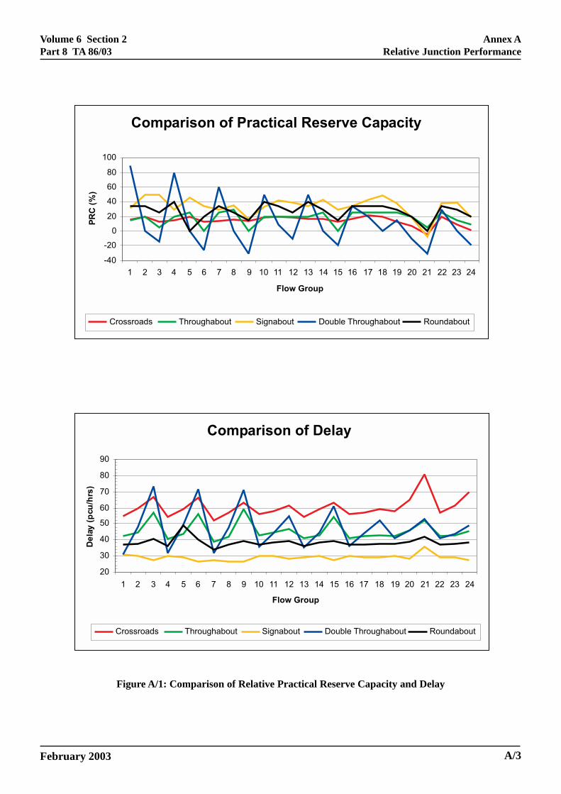
18. The results of the tests in terms of both practicalreserve capacity and delay are shown on Figure A/1.
February 2003
Volume 6 Section 2Part 8 TA 86/03
Feb
Annex ARelative Junction Performance
Figure A/1: Comparison of Relative Practical Reserve Capacity and Delay
Comparison of Delay
20
30
40
50
60
70
80
90
1 2 3 4 5 6 7 8 9 10 11 12 13 14 15 16 17 18 19 20 21 22 23 24
Flow Group
De
lay
(pcu
/hrs
)
Crossroads Throughabout Signabout Double Throughabout Roundabout
Comparison of Practical Reserve Capacity
-40
-20
0
20
40
60
80
100
1 2 3 4 5 6 7 8 9 10 11 12 13 14 15 16 17 18 19 20 21 22 23 24
Flow Group
PR
C(%
)
Crossroads Throughabout Signabout Double Throughabout Roundabout
ruary 2003 A/3

Volume 6 Section 2Part 8 TA 86/03
Annex ARelative Junction Performance
Initial Selection
19. It is likely that the initial selection will bebetween a single node layout such as a signalled crossroads or the Sig-nabout, and some form of multi-noderoundabout gyratory system.
20. The through-about and double-through-aboutjunctions are most likely to be considered as specificmodifications if the initial testing indicates theselayouts may suit the specific conditions.
21. The principal considerations in the decisionprocess are likely to be:
• Capacity;
• Geometry;
• Number of arms needed at the junction;
• Vehicle speeds;
• Pedestrian and cycle facilities;
• U turn manoeuvres;
• Right turn manoeuvres;
• Driver comprehension;
• Public transport provision.
Capacity (under test conditions)
Crossroads: the capacity is relatively stable andassumes fully signalled right turns.
Roundabout: the capacity is likely to be higher than acrossroads but more sensitive tovariations in turning movements. Thetest conditions assume optimum laneuse. The capacity of the roundabout issensitive to lane use patterns,particularly on the circulatorycarriageway.
Sig-nabout: likely to return highest capacity of thethree junction types.
A/4
Geometry
Crossroads: likely to result in the most compactfootprint at the intersection but mayrequire longer flares on the approaches.
Roundabout: likely to result in the largest footprint atthe intersection.
Sig-nabout: with its short cycle time the junctionmust make use of short, wide flares atthe intersection.
Number of arms
Crossroads: 4 arms are considered to be thepractical maximum as more will requireadditional stages in the cycle which willquickly erode the capacity.
Roundabout: can accommodate more than four arms.Signal co-ordination becomes moredifficult as the number of signalisedarms increases.
Sig-nabout: this junction can only be used with 4arm intersections.
Vehicle speeds
Crossroads: there is no natural speed reducinggeometry on the ahead trafficmovement.
Roundabout: the geometry of the junction naturallyresults in a tendency for vehicle speedsto reduce on the approaches.
Sig-nabout: ahead traffic tends to be slowed by thedeflection provided, but theuncontrolled, gap seeking nature of theright turns means the junction must notbe used on high speed roads.
Pedestrian and cycle facilities
22. The question of pedestrian and cycle facilities inrespect of the various types of junction has beenconsidered in Chapter 3.
February 2003

Volume 6 Section 2Part 8 TA 86/03
Annex ARelative Junction Performance
U turn manoeuvres
Crossroads: U-turn manoeuvres cannot beaccommodated at the point of conflict.However, observations show that theydo occur and banning such movementscan create problems with enforcementand safety elsewhere in the network.
Roundabout: U-turn manoeuvres are accommodated.
Sig-nabout: U-turn manoeuvres cannot beaccommodated at the point of conflict.
Right turn manoeuvres
Crossroads: Right turn manoeuvres can be fullysignalled at the point of conflict.
Roundabout: Right turn manoeuvres are carried outusing the circulatory carriageway. Theconflicts are dispersed spatially at theintermediate nodes.
Sig-nabout: Right turn manoeuvres are uncontrolledand opposed. They are carried out in 2lanes during the intergreen period andthrough gaps in the opposing traffic.
Driver comprehension
Crossroads: common form of junction control that iswell understood.
Roundabout: common form of junction control that iswell understood.
Sig-nabout: unusual form of junction control.Drivers may misunderstand theuncontrolled nature of the right turns.
These principal characteristics are summarised in TableA-1 on the following page.
February 2003 A/5

Volume 6 Section 2Part 8 TA 86/03
Annex ARelative Junction Performance
Principal Signal Controlled Signalised Roundabout Sig-naboutCharacteristics Crossroads or Gyratory
Capacity Must be determined by Must be determined by Likely to have highesttesting testing capacity at short cycle times
Geometry Smaller footprint than Generally largest footprint Similar local footprint togyratory but may use crossroads with short locallonger approach flares flares
No. of arms Practical maximum of 4 Can accommodate more Must use 4 armsat point of conflict than 4 arms
Vehicle speeds Generally no deflection to Speed reduction is Some deflection to slowslow ahead traffic inherent in the geometry down ahead movements.movements. Should not be of the junction Should not be used whereused where approach speeds approach speeds are highare high
Pedestrian & cycle At-grade facilities can be At grade measures often Difficult to provide at gradeprovided but can reduce require numerous crossing pedestrian crossing facilitiescapacity points. If there are high
volumes of pedestrians andcyclists and high trafficspeeds then segregationshould be considered
U turn facility No Yes No
Right turn provision Fully controlled right turns Right turn conflicts are Right turns are gap seekingcan be provided resolved geometrically in 2 lanes
Driver comprehensibility Good Good Possible confusion overright turn control
Table A-1 Principal jun
23. The relative performance of the remainingjunction layouts are considered below.
Through-about
24. Consideration of a through-about is most likelyto arise as a further test of a signalised roundabout incircumstances where there is a dominant trafficmovement across the junction on the major road.
25. Figure A/1 may give the impression that thethrough-about does not perform as well as thesignalised roundabout. The lower performance is due inpart to an assumption that the control strategy wouldclear through traffic from the central links in bothdirections before giving right of way to the circulatorycarriageway. This would ensure maximum storagespace for any vehicles turning right into the centrallinks from the circulatory carriageway.
A/6
ction characteristics
26. If the clear out period is removed in one or bothdirections then lost time will be reduced and capacitymay be improved. It is inevitable that some throughtraffic will be stopped in the internal links and in thissituation consideration will need to be given to storagespace for any vehicles turning right into the centrallinks from the circulatory carriageway.
27. For small through-abouts the clear out periodmay be important from a safety point of view as driverswill not expect to be stopped at a close second stopline.As the through-about becomes larger, stopping the tailend of a platoon in the central links becomes less of aproblem as the reservoir space becomes greater.
28. For large through-abouts with a central link in therange of 200 metres or more, co-ordination may not benecessary because the two nodes can be treated asseparate junctions. In these situations the co-ordination
February 2003

Volume 6 Section 2Part 8 TA 86/03
Annex ARelative Junction Performance
and capacity of the whole junction may become moreimportant than the co-ordination through the link.
29. Where there is no clear out period, and/or whenvehicles turn right into the central links from thecirculatory carriageway, consideration will also need tobe given to the starting co-ordination of the nodescontrolling the central links.
30. The through-about exhibits the following generaljunction characteristics in addition to those of thesignalised roundabout:
• the natural deflection provided by the roundaboutis removed from the traffic on the through linksconsequently vehicle speeds may not be reduced;
• the right turn from the traffic streams using thecentral links is carried out using the circulatorycarriageway;
• these junctions are not common and drivers maynot easily understand the nature of the right turnfrom the traffic streams using the central links.
Double-through-about
31. The double-through-about gives very goodperformance with flow groups with low turningmovements but this deteriorates rapidly as turningmovements increase. The junction could be consideredwhere the traffic patterns show dominant movementsacross the junction from all four arms.
32. The short central links have limited storage spacefor queuing traffic and a control strategy of clearing thecentral links of through traffic on stage changes isimportant.
33. This junction is unique and drivers may noteasily understand the nature of the right turn from thetraffic streams using the central links.
Modifications or Hybrids
34. The junction testing may suggest options that aremodifications to the generic layouts and result inHybrids with some of the features of several junctions.Some examples are given below:
February 2003
Signal Controlled Crossroads
35. Double node crossroads.
Figure A/2: Double Node Crossroads
In this modification the single node has been stretchedalong the axis of one of the arms to form a two-nodejunction. The feature of this arrangement is that areservoir is formed into which right turning traffic canmove and stack while their parent traffic streams haveright of way. These vehicles then clear the junctionwhen the two opposing arms gain right of way. Anexample of this technique is illustrated in Annex C.
Signalised Roundabout
36. Bypassed node.
Figure A/3: Bypassed Node
Here a critical stream has been routed past one of thenodes on the circulatory carriageway by constructing alink in the central island. An example of this techniqueis illustrated in Annex C.
A/7

Volume 6 Section 2Part 8 TA 86/03
Annex ARelative Junction Performance
Through-about
37. Half Through-about.
Figure A/4: Half Through Node
In this modification a critical stream has been routedacross the central carriageway by means of a one waylink. An example of this technique is illustrated inAnnex C.
38. It can be seen from the above options and thepractical examples in Annex C that a solution to aspecific situation may incorporate a combination offeatures from several of the generic junction types inthe form of a hybrid, and a flexible approach to theselection and design process will often result in asatisfactory conclusion.
February 2003A/8
Volume 6 Section 2Part 8 TA 86/03
February 2003
ANNEX B: TRAFFIC FLOW GROUPS USED FORCAPACITY TESTS
General
This annex details the traffic flows which were used totest the junction layouts described in Chapter 3.
The Flow Sets
Each of the tests was carried out with a total inflow tothe junction of 6000 vehicles. This represented a typicalpeak hour traffic flow through a semi-urban crossroads.These 6000 vehicles were allocated to the approacharms in eight sets of traffic flows. Each of these eightsets allocated traffic to the approach arms in differentproportions.
The Flow Groups
Each of the eight flow sets was then further sub-dividedinto three flow groups. Each of these flow groupspresents the junctions with varying proportions ofturning traffic.
Each junction was therefore tested with 24 groups oftraffic flows each representing a different pattern oftraffic movements between the four approach arms.
While the possible combinations of traffic movementsthrough a four-arm junction are numerous, the flow setsused cover most of the situations likely to occur inpractice.
The results of the tests are discussed in Annex A.
Figure B/1 shows all of the flow groups in greaterdetail.
Annex BTraffic Flow Groups Used for Capacity Tests
B/1

Volume 6 Section 2Part 8 TA 86/03
February 2003
Figure B/1: Flow Groups Used in Capacity Tests (Page 1)
B/2
Annex BTraffic Flow Groups Used for Capacity Tests
Set 1
Traffic flow into junction Flow Group 1 Flow Group 2 Flow Group 3
B 10% 80% 10% 20% 60% 20% 30% 40% 30%
1500
A C 10% 10% 20% 20% 30% 30%
1500 1500 80% 80% 60% 60% 40% 40%
10% 10% 20% 20% 30% 30%
1500
D 10% 80% 10% 20% 60% 20% 30% 40% 30%
Set 2
Traffic flow into junction Flow Group 4 Flow Group 5 Flow Group 6
B 10% 80% 10% 20% 60% 20% 30% 40% 30%
1200
A C 10% 10% 20% 20% 30% 30%
1800 1800 80% 80% 60% 60% 40% 40%
10% 10% 20% 20% 30% 30%
1200
D 10% 80% 10% 20% 60% 20% 30% 40% 30%
Set 3
Traffic flow into junction Flow Group 7 Flow Group 8 Flow Group 9
B 10% 80% 10% 20% 60% 20% 30% 40% 30%
900
A C 10% 10% 20% 20% 30% 30%
2100 2100 80% 80% 60% 60% 40% 40%
10% 10% 20% 20% 30% 30%
900
D 10% 80% 10% 20% 60% 20% 30% 40% 30%
Set 4
Traffic flow into junction Flow Group 10 Flow Group 11 Flow Group 12
B 10% 80% 10% 20% 60% 20% 30% 40% 30%
1500
A C 15% 15% 15% 15% 15% 15%
1500 1500 70% 70% 70% 70% 70% 70%
15% 15% 15% 15% 15% 15%
1500
D 10% 80% 10% 20% 60% 20% 30% 40% 30%

Volume 6 Section 2Part 8 TA 86/03
February 2003
Figure B/1: Flow Groups Used in Capacity Tests (Page 2)
Annex BTraffic Flow Groups Used for Capacity Tests
B/3
Set 5
Traffic flow into junction Flow Group 13 Flow Group 14 Flow Group 15
B 15% 70% 15% 15% 70% 15% 15% 70% 15%
1200
A C 10% 10% 20% 20% 30% 30%
1800 1800 80% 80% 60% 60% 40% 40%
10% 10% 20% 20% 30% 30%
1200
D 15% 70% 15% 15% 70% 15% 15% 70% 15%
Set 6
Traffic flow into junction Flow Group 16 Flow Group 17 Flow Group 18
B 10% 80% 10% 20% 60% 20% 30% 40% 30%
1200
A C 15% 15% 15% 15% 15% 15%
1800 1800 70% 70% 70% 70% 70% 70%
15% 15% 15% 15% 15% 15%
1200
D 10% 80% 10% 20% 60% 20% 30% 40% 30%
Set 7
Traffic flow into junction Flow Group 19 Flow Group 20 Flow Group 21
B 15% 70% 15% 15% 70% 15% 15% 70% 15%
1200
A C 15% 15% 15% 15% 15% 15%
1800 1800 65% 70% 55% 70% 45% 70%
20% 15% 30% 15% 40% 15%
1200
D 15% 70% 15% 15% 70% 15% 15% 70% 15%
Set 8
Traffic flow into junction Flow Group 22 Flow Group 23 Flow Group 24
B 20% 65% 15% 30% 55% 15% 40% 45% 15%
1200
A C 15% 15% 15% 15% 15% 15%
1800 1800 70% 70% 70% 70% 70% 70%
15% 15% 15% 15% 15% 15%
1200
D 15% 70% 15% 15% 70% 15% 15% 70% 15%

Volume 6 Section 2Part 8 TA 86/03
NAL CONTROLLED
Annex CCompound Signal Controlled Junctions
ANNEX C: COMPOUND SIGJUNCTIONS
1. A Compound Signal Controlled Junction (CSCJ)can be defined as a group of separate, but inter-related,‘simple’ signal controlled junctions. A signalisedroundabout could be considered as a special case of aCSCJ. Most of the junctions considered so far fit into aparticular generic type of either a crossroads or a formof gyratory. The CSCJ can be any combination ofsimple junctions arranged to suit both topography anddesire lines. There are three fundamental principlesinvolved in the design of a CSCJ which are brieflydescribed as follows:
i. All major traffic conflicts signalised
In order to optimise capacity and safety, all majortraffic conflicts should be signalised. Light trafficmovements, which would typically only require avery short green, could be controlled under a‘give way’, thereby reducing the number ofindividual junctions.
ii. Minimum conflicts at a single junction
The capacity of any given approach to thejunction is a direct function of green time andnumber of lanes. If the number of conflicts canbe minimised at each individual node, green timecan be maximised and the cycle time can be keptto a minimum. Hence, it is desirable to reduce thenumber of conflicts at each junction to two.
iii. Majority flows given the most direct route
It is important that the majority flows are given adirect route through the junction to minimisedelay and keep saturation flows to a maximum.The minority flows may need to be diverted toenable the number of conflicting movements atany one individual junction to be kept to aminimum.
February 2003
iv. Co-ordination and safety relationships
The co-ordination of closely spaced signalcontrolled junctions is a vital factor in theperformance and safety of the overall junction.Front and tail end co-ordination must beconsidered carefully when linking the individualjunctions. Once established, it may not bedesirable to alter the sequence beyond definedlimits and it may be necessary to protect thesequence integrity.
2. There are many CSCJs around the UK that mayconsist of two or three small junctions. The largepurpose built CSCJs which cater for five or moreintersecting arms are few in number but are increasing.West Yorkshire built the first major CSCJ (Sheepscar)in the mid 1980s which consists of seven junctions.They have recently added another on the Leeds InnerRing Road.
C/1

Volume 6 Section 2Part 8 TA 86/03
Annex CCompound Signal Controlled Junctions
Figure C/1: Two Node Crossroads Between Western Boulevard and Nuttall Roadin Nottingham
February 2003C/2

Volume 6 Section 2Part 8 TA 86/03
Annex CCompound Signal Controlled Junctions
3. This “stretched” two node crossroads was aconversion of an original roundabout. The crossroadswas stretched to create a high capacity storage reservoirin the centre of the junction to accommodate rightturning traffic from two of the arms.
February 2003
4. The layout allows these two right turns to occurin parallel with their parent traffic streams.
Figure C/2: Half Through-About - Sherwin Arms, Nottingham
A52
A52
A52
C/3

Volume 6 Section 2Part 8 TA 86/03
Annex CCompound Signal Controlled Junctions
5. This “partial through-about” signalised junctiondesign was converted from a conventional five armroundabout.
6. The route through the centre of the junctioncarries traffic in one direction only and the junctiondoes not incur the lost time generated by the central link
C/3
clearance period associated with a conventionalhamburger junction.
7. A feature of the junction is that traffic on themain A52 Trunk Road makes a dog leg movementthrough the roundabout. Only the conflicts with the A52are signalised, with the other three arms operatingunder priority control.
Figure C/3: Traffic Signal Controlled Gyratory - Exe Bridges in Exeter
February 2003

Volume 6 Section 2Part 8 TA 86/03
Annex CCompound Signal Controlled Junctions
8. This traffic signal controlled gyratory has beenmodified to incorporate a bus/lorry lane and sharedcycle/pedestrian facility.
9. The bus/lorry lane, shown in red on the plan hasbeen incorporated at the expense of an existing trafficlane reducing the circulatory carriageway from 4 to 3lanes on the east of the junction. The shared cycle/pedestrian facility has been segregated from the roadusing pedestrian guard railing and connects to thesubways running under the gyratory.
February 2003 C/4

Volume 6 Section 2Part 8 TA 86/03
Annex DDefinitions
ANNEX D: DEFINITIONS
General
1. This Annex defines the principal terms andconcepts which are used in the geometric design oflarge signal controlled junctions.
2. The definitions published in this document are inaddition to those detailed in TD 50 (DMRB 6.2.3).
Definitions:
All Red All sets of signal heads displayred simultaneously stopping allvehicular traffic – may be used toallow pedestrians to cross ajunction.
Conflict A condition where twoconflicting signal phases areamber or green at the same time.
Conflict Point The point where at least oneconflict could occur between twotraffic streams if they wereadmitted onto the intersection atthe same time.
Control System A method of co-ordination of anysystem usually by reference to acentral controlling centre.
Controller The logic equipment thatcontains the algorithm forcontrolling the signalisedintersection.
Co-ordination A system of linking adjacenttraffic signals with a commoncycle time or multiple thereof.
Cycle Time The time taken for one completesequence of the operation of thetraffic signals.
Delay The difference between the timeit takes a vehicle to pass througha signal controlled junction, ornetwork, and the time it wouldtake to travel the same route ifthere were no control facilities.
February 2003
Filter Arrow The electrical circuit thatcontrols a single aspect greenarrow head positioned alongsidea 3 aspect signal head controlledby a separate phase (referred toas the associated main phase).The Filter Arrow always turns togreen while the associated mainphase is at red and normallyterminates green at the momentwhen the main phase starts green
Gap Change A change in traffic signalindication that occurs on thetermination of a vehicleextension period.
Green Man Signal A green aspect specifically toinform pedestrians.
Gyratory Gyratories are road systemswhich consist of one-way linksconnected together, so as to makeit possible for traffic to circulatealong one or more links beforeexiting. They can take a varietyof forms but are mostcharacterised by ‘roundabouts’that are usually built as entitiesrather than configured from anumber of existing roads.(Transport in the UrbanEnvironment. IHT 1997)
Indicative Arrow The electrical circuit whichcontrols a single aspect greenarrow head (arrow pointing to theright) positioned alongside thesecondary signal (i.e. far side ofjunction) of the associated mainphase signal head. This is usedonly to assist opposed right turns.The indicative green arrow canonly appear while the associatedmain phase is at green andnormally finishes with thetermination of the associatedmain phase green period. Notethat the term filter should notbe used in this context.
D/1

Volume 6 Section 2Part 8 TA 86/03
Annex DDefinitions
Lost Time The sum of periods of timeduring a single cycle when novehicular traffic is moving.
Merging The action of vehicles changinglanes by moving into gapsbetween vehicles.
Opposed Right A right turn manoeuvre whichTurn may, for part of the signal cycle,
be carried out while giving wayto oncoming or opposing traffic.Note that this method of rightturn control is only consideredappropriate with single right turnlanes (except at a sig-nabout).
Pedestrian A facility to enable pedestrians toCrossing cross the carriageway, for
example Pelicans, Puffins,Toucans, Zebras.
Pedestrian Stage A specific period within thesignal cycle when onlypedestrian phases are permittedto display a green signal.
Platoon A number of vehicles travellingclosely as a group.
Red Man Signal A red light display to advisepedestrians not to cross.
Reserve Capacity Expressed as a percentage, it isthe amount by which trafficflows at a junction can beincreased until the theoreticalmaximum capacity of thejunction is reached. It representsthe amount of additional trafficthat can pass through the junctionbefore saturation occurs.
Saturation The condition where an arm of ajunction does not, during itsgreen period of the cycle, fullydischarge the queue of trafficwhich has built up at the stoplineduring the preceding red period.
SCOOT Split Cycle Offset OptimisationTechnique.
Sh
D/2
ort Lanes These may exist whenever thenumber of lanes at the stopline(s)on an arm on the junction isgreater than the number of lanesfeeding through from the nextjunction upstream. They can beformed by constructing localwidening of the carriageway atthe junction to increase thestopline capacity. They oftenoccur however as a result ofparked or other stationaryvehicles obstructing what wouldotherwise have been a fullkerbside lane.
February 2003


![Phase-Locking Josephson Junctions Arraysing.univaq.it/energeti/research/Fisica/jamapro12.pdf · junction-based systems such as multi-stacked junctions [5Š7], large planar arrays](https://static.fdocuments.net/doc/165x107/5ec5593513b08355f20aa454/phase-locking-josephson-junctions-junction-based-systems-such-as-multi-stacked-junctions.jpg)