DMRB VOLUME 3 SECTION 1 PART 5 - BA 93/09 - STRUCTURAL ASSESSMENT OF BRIDGES WITH …€¦ · ·...
46
VOLUME 3 HIGHWAY STRUCTURES: INSPECTION AND MAINTENANCE SECTION 1 INSPECTION PART 5 BA 93/09 STRUCTURAL ASSESSMENT OF BRIDGES WITH DECK HINGES SUMMARY This Advice Note provides guidance on the structural assessment of deck hinges and presents a strategy for the management of Highway Agency bridges with deck hinges. It replaces the information given in Interim Advice Note 51/03. INSTRUCTIONS FOR USE 1. Remove Contents pages from Volume 3 and insert new Contents pages for Volume 3 dated February 2009. 2. Insert new Advice Note BA 93/09 into Volume 3 Section 1. 3. Please archive this sheet as appropriate. Note: A quarterly index with a full set of Volume Contents Pages is available separately from The Stationery Office Ltd. DESIGN MANUAL FOR ROADS AND BRIDGES February 2009
Transcript of DMRB VOLUME 3 SECTION 1 PART 5 - BA 93/09 - STRUCTURAL ASSESSMENT OF BRIDGES WITH …€¦ · ·...
volume 3 highway structures: inspection and maintenance section 1 inspection
part 5
ba 93/09
structural assessment of bridges with deck hinges
summary
This Advice Note provides guidance on the structural assessment of deck hinges and presents a strategy for the management of Highway Agency bridges with deck hinges. It replaces the information given in Interim Advice Note 51/03.
instructions for use
1. Remove Contents pages from Volume 3 and insert new Contents pages for Volume 3 dated February 2009.
2. Insert new Advice Note BA 93/09 into Volume 3 Section 1.
3. Please archive this sheet as appropriate.
Note: A quarterly index with a full set of Volume Contents Pages is available separately from The Stationery Office Ltd.
design manual for roads and bridges
february 2009

design manual for roads and bridges ba 93/09 volume 3, section 1, part 5
the highways agency
scottish government
welsh assembly government llywodraeth cynulliad cymru
the department for regional development northern ireland
Structural Assessment of Bridges with Deck Hinges
Summary: This Advice Note provides guidance on the structural assessment of deck hinges and presents a strategy for the management of Highway Agency bridges with deck hinges. It replaces the information given in Interim Advice Note 51/03.

february 2009
volume 3 section 1 part 5 ba 93/09
registration of amendments
amend no
page no signature & date of incorporation of
amendments
amend no page no signature & date of incorporation of
amendments
registration of amendments

february 2009
volume 3 section 1 part 5 ba 93/09
registration of amendments
amend no
page no signature & date of incorporation of
amendments
amend no page no signature & date of incorporation of
amendments
registration of amendments

volume 3 highway structures: inspection and maintenance section 1 inspection
part 5
ba 93/09
structural assessment of bridges with deck hinges
contents
Chapter
1. Introduction
2. Assessment Methodology
3. Strength Assessment
4. References
5. Enquiries
Annex A Management Strategy Flowchart
Annex B Typical Hinge Details
Annex C Initial Prioritisation
Annex D Example Calculation
Annex E Highways Agency SMIS Requirements
Annex F Risk Assessment
Annex G Highways Agency Management Strategy
design manual for roads and bridges
february 2009

volume 3 section 1 part 5 ba 93/09
chapter 1 introduction
1. introduction
general
1.1 This Advice Note supersedes Interim Advice Notes IAN 40/01 and IAN 51/03 which implemented an interim management strategy for reinforced concrete hinges in the decks of suspended span bridges on the Highways Agency road network in England. However, the main body of the Advice Note is concerned with guidance on the structural assessment of deck hinges which forms a part of the strategy. The management strategy for Highways Agency bridges is included at Annex G.
a) The scope of this document includes all types of bridges with hinge deck details as illustrated in Annex B and described in 1.2 and 1.3.
b) The management of the programme has been linked to the Structures Management Information System (SMIS) for bridges on the Highways Agency road network in England (see Annex E).
c) Information has been included on the use of non-destructive testing (NDT) techniques (see Annex G1.16 to G1.20).
d) Guidelines on the structural assessment of hinges, based on experimental results, are provided (see Annex G1.11 and main text in Advice Note).
e) Remedial options are identified (see Annex G2).
f) Timescales have been outlined (see Annex G1.3 and G2).
1.2 A typical hinge detail (similar to that shown in Annex B) consists of a narrowing of the concrete section in flat slab or beam and slab decks to form a throat, through which steel reinforcement passes between the cantilever and suspended span. There are known variations to this arrangement, with differing construction sequences, details of reinforcement, types of reinforcement, skews and edge details, particularly where service bays are included. It is important for assessment to establish the reinforcement configuration and type, and if any reinforcement is misplaced or damaged.
february 2009
1.3 Structures with a different detail known as a Wichert truss are also to be included within the scope of the strategy. These structures were used in areas subject to significant differential settlement such as mining subsidence.
1.4 In England a National Structures Programme Module (NSP) for the SMIS has been developed to allow input and management of data associated with the hinge deck strategy. This is detailed in Annex E.
1.5 This Advice Note should be used forthwith for all trunk road bridges in the UK and for all bridges in Northern Ireland, including those currently being assessed provided that in the opinion of the Overseeing organisation, this would not result in significant additional expense or delay progress.
1/1
volume 3 section 1 part 5 ba 93/09
logy
chapter 2 assessment methodology
2. assessment methodo
background
2.1 Hinge joints were introduced into bridge decks as a means of simplifying the design and standardising details on bridges having a range of span and functional requirements. They were also used to mitigate the effects of movements due to temperature, creep shrinkage and differential settlement. The disadvantages of hinge joints are that they are not easily accessible for inspection or maintenance due to their form, and being mostly located over or under live traffic lanes. They are vulnerable to deterioration in the event of bridge deck waterproofing failure, where chlorides seeping through the joint can cause reinforcement corrosion. This reinforcement is crucial to the integrity of the joint, and the loss of reinforcement section, or associated concrete spalling can induce higher stresses, leading to eventual failure by yielding. It has been noted during inspections that the majority of hinges have cracks running through the full depth of the throat, indicating that the hinge has been, or is subject to tension and may not be working as originally intended. This complicates any structural assessment of the hinge, and also brings into question the fatigue endurance of the reinforcement.
structural strength
2.2 This Advice Note presents guidelines for the assessment of deck hinges. Assessment is carried out to check the structural adequacy of the hinge and its ability to carry the specified traffic loading. It should be carried out in two parts:
1. structural analysis: to determine the range of load effects on the hinge joint;
2. analysis of hinge: to calculate the capacity of the hinge in its current condition.
2.3 Structural analysis is performed assuming that the hinges behave as pinned supports. Analysis should consider the normal local load effects specified by BD 21 such as accidental wheel loads, thermal, and differential settlement, and the presence of particular design features such as cantilever pipe bays, skew and dog-leg joints. Skews greater than 10o should be taken into account in the structural analysis. Limited testing has indicated that skew does not affect the strength of a hinge and the methodology presented in Chapter 3 can be used.
february 2009
2.4 One of the objectives of the assessment is to identify a deterioration trigger point to feed into a monitoring and inspection regime to assist in determining when interim measures are required. To facilitate this, a sensitivity analysis should be carried out to determine the influence of variations in the condition of the structure. Defects can be categorised under loss of throat reinforcement cross-section, reinforcement yielding, misplaced reinforcement, concrete debonding, and loss of link reinforcement. A range of severity of each defect (and any other factors) should be considered, and the position of the structure within this range determined. For the sake of consistency of reporting, sensitivity should be expressed in terms of ‘usage factor’, defined as the ratio of the ultimate load effect to the assessed hinge capacity. Technical Approval procedures in accordance with BD 2 will apply to this assessment work.
fatigue
2.5 A fatigue assessment should be carried out. Fatigue failures occur under the frequent application of quite small stress ranges due, typically, to the passage of individual vehicles. Fatigue damage accumulates under repeated loading and the rate of damage accumulation is very sensitive to the stress range experienced at the fatigue site as the load passes.
2.6 In order to perform a fatigue check on the bars at the hinge it is necessary to evaluate the stresses generated at the fatigue site. A simplified methodology for doing this is presented in Chapter 3.
preliminary assessment
2.7 The assessment methodology outlined in Chapter 3 entails a degree of complexity that may not be required in many cases. It is recommended that preliminary analysis using simplifying assumptions be carried out as this may be sufficient to demonstrate adequate strength. As a first approximation, the shear capacity of the hinge can be taken as the vertical component of the yield strength of the tension and compression hinge bars. A check should be carried out to ensure that there is sufficient shear steel to carry the force in the compression hinge bars. This will yield a conservative estimate of the shear capacity of the hinge, provided due allowance is given to the condition of the reinforcement in and around the hinge (see Clauses 3.9 – 3.11).
2/1

volume 3 section 1 part 5 ba 93/09
chapter 2 assessment methodology
detailed assessment
2.8 If the adequacy of the joint cannot be demonstrated using the simplified assumptions of 2.7, then the full procedure outlined in Chapter 3 should be carried out. An example calculation is presented in Annex D.
2.9 Alternative methods can be used provided it is demonstrated that the hinge behaviour is adequately modelled.
february 20092/2
volume 3 section 1 part 5 ba 93/09
chapter 3 strength assessment
3. strength assessment
strength mechanism
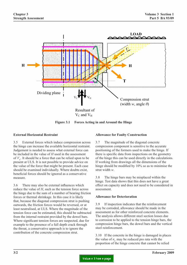
3.1 Shear force is carried through the hinge by the following force components whose affects are additive (see Figure 3.1):
1. The tension in the hinge bars (T): these bars contribute a vertical force equal to the resolved vertical component of their yield strength.
2. The compression in the hinge bars (C): These bars contribute a vertical force equal to the resolved vertical component of their yield strength. This component acts on the deck shear truss as a vertical load through the intersection of the centrelines of the diagonal bars and the top or bottom reinforcement of the deck. Because it is usual in hinge reinforcement systems for the tension and compression bars to match each other in number, size and angle, and because it is assumed that compression yield equals tension yield, the horizontal force component of the compression hinge bars matches that of the tension hinge bars. Together they generate no net longitudinal force through the hinge.
3. Diagonal concrete compression: This component only acts if there is some horizontal compression force at ULS (H) acting across the hinge. At ULS there can be an internal force reacting against the horizontal restraint provided by the dowel bars acting at yield. The horizontal force may also have an external source, such as the horizontal reaction generated in a deck due to inclined columns or mass abutments. This situation is discussed below. It is likely that this component of the strength of the hinge is limited by the strength of the link and C bar system in the deck on both sides of the hinge.
3.2 Dowel action may also contribute to the strength of the hinge but will only be fully mobilised after the diagonal concrete compression strut has failed. Because of the complexities involved, it is recommended that dowel action be ignored.
sol
3.3in tconhorgovTheavastreof twhcomstreverthetopis ashostru
3.4protheresuC-bNoencextSubresithisstruuntcomhincomtotathe
february 2009
ution procedure
Iteration is needed to find the strength available he system. A straight, diagonal compression strut is sidered to act through the hinge, at an angle θ to the izontal (see Figure 3.1). The width of the strut, w, is erned by the geometry of the hinge and the angle θ. maximum force in the strut (VC) is limited by the ilable horizontal restraint H, and the compressive ngth of the concrete. Thus the vertical component he strut force is the lesser of H tanθ and w b σC sinθ, ere b is the width of the cross section and σC is the pressive strength of the concrete in the hinge. The
ngth σC is taken as 0.67 times the cube strength. The tical force is assumed to act through the point where diagonal force meets the mid-depth of the horizontal or bottom reinforcement in the deck. The strut force lso limited by the available vertical steel which uld be sufficient to carry the combined force in the t and compression hinge bars.
The solution can be found using the following cedure. Consider a vertical dividing plane through deck some distance from the hinge and find the ltant vertical force due to all the effective links and ars between the plane and the hinge, acting at yield.
te that links are only considered effective if they lose the tension and compression hinge bars and they end for at least half the depth of the concrete section. tract from this resultant the vertical force needed to st the compression hinge bars. The line of action of resultant is calculated: this defines the angle θ of the t force. The position of the dividing plane is adjusted il there are just sufficient links to carry the diagonal pressions from the concrete and the compression
ge bars. The contribution from the concrete diagonal pression is VC for the associated value of θ. The l shear capacity is VC plus the vertical component of
tension and compression hinge bars.
3/1
volume 3 section 1 part 5 ba 93/09
chapter 3 strength assessment
eel which should be sufficient to carry the
H
LOAD
C
T
Compression strut (width w, angle θ)
figure 3.1 forces actin
limited by the available vertical st
combined force in the strut and com 3.4 The solution can be found using t
dividing plane through the deck sresultant vertical force due to all tplane and the hinge, acting at yeffective if they enclose the tensiextend for at least half the depth resultant the vertical force neededline of action of this resultant is calforce. The position of the dividinsufficient links to carry the diagonacompression hinge bars. The compression is VC for the associateplus the vertical component of the t
External horizontal restraint 3.5 External forces which induce comp
available horizontal restraint. Judgforce can be included in the value obe a force that can be relied uponprovide advice on the value of thshould be examined individually. Wbe ignored as a conservative meas
H
Resultant oVC and VH
Dividing plane VC VH
Figure 3.1 Forces acting
external horizontal restraint
3.5 External forces which induce compression across the hinge can increase the available horizontal restraint. Judgement is needed to assess what external force can be included in the value of H used in the assessment of VC. It should be a force that can be relied upon to be present at ULS. It is not possible to provide advice on the value of the force that might be present. Each case should be examined individually. Where doubts exist, beneficial forces should be ignored as a conservative measure.
3.6 There may also be external influences which reduce the value of H, such as the tension force across the hinge due to the sum of a number of bearing friction forces or thermal shrinkage. In this case it is likely that, because the diagonal compression strut is pushing outwards, the friction forces would be reversed, or at least neutralised, at ULS. Where the magnitude of the tension force can be estimated, this should be subtracted from the internal restraint provided by the dowel bars. Where significant tension forces are suspected, due for example to the presence of a full depth crack through the throat, a conservative approach is to ignore the contribution of the concrete compression strut.
3/2
3.6 There may also be external
the tension force across the
g in and around the hinge
pression hinge bars.
he following procedure. Consider a vertical ome distance from the hinge and find the he effective links and C-bars between the ield. Note that links are only considered on and compression hinge bars and they of the concrete section. Subtract from this to resist the compression hinge bars. The culated: this defines the angle θ of the strut g plane is adjusted until there are just l compressions from the concrete and the
contribution from the concrete diagonal d value of θ. The total shear capacity is VC
ension and compression hinge bars.
ression across the hinge can increase the ement is needed to assess what external f H used in the assessment of VC. It should to be present at ULS. It is not possible to e force that might be present. Each case here doubts exist, beneficial forces should
ure.
influences which reduce the value of H, such as
f
in and around the hinge.
allowance for faulty construction
3.7 The magnitude of the diagonal concrete compression component is sensitive to the accurate positioning of the formers used to make the hinge. If there is specific data from inspections on the geometry of the hinge this can be used directly in the calculations. If working from drawings all the dimensions of the hinge should be modified by 10% so as to minimise the strut width w.
3.8 The hinge bars may be misplaced within the hinge. Test data shows that this does not have a great effect on capacity and does not need to be considered in assessment.
allowance for deterioration
3.9 If inspection indicates that the reinforcement may be corroded, allowance should be made in the assessment as for other reinforced concrete elements. The analysis allows different steel section losses due to corrosion to be applied to the tension hinge bars, the compression hinge bars, the dowel bars and the vertical steel reinforcement.
3.10 If the concrete in the hinge is damaged in places the value of σC may be reduced pro rata with the proportion of the hinge concrete that cannot be relied
february 2009 hinge due to the sum of a number of bearing
volume 3 section 1 part 5 ba 93/09
chapter 3 strength assessment
upon. If the throat concrete is seriously damaged, it may be necessary to omit the compression strut component completely.
3.11 Testing has shown that local debonding of the reinforcement in the hinge does not affect the capacity.
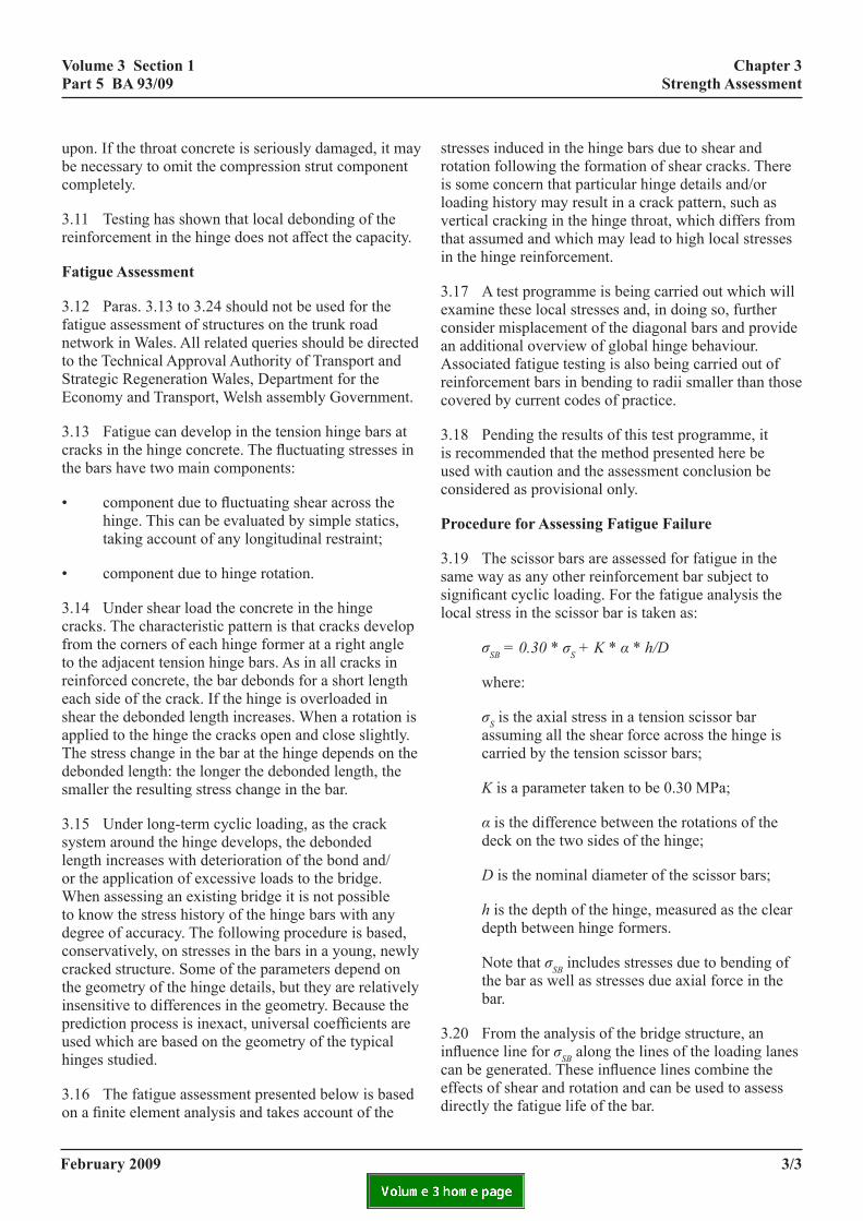
fatigue assessment
3.12 Paras. 3.13 to 3.24 should not be used for the fatigue assessment of structures on the trunk road network in Wales. All related queries should be directed to the Technical Approval Authority of Transport and Strategic Regeneration Wales, Department for the Economy and Transport, Welsh assembly Government.
3.13 Fatigue can develop in the tension hinge bars at cracks in the hinge concrete. The fluctuating stresses in the bars have two main components:
• component due to fluctuating shear across the hinge. This can be evaluated by simple statics, taking account of any longitudinal restraint;
• component due to hinge rotation.
3.14 Under shear load the concrete in the hinge cracks. The characteristic pattern is that cracks develop from the corners of each hinge former at a right angle to the adjacent tension hinge bars. As in all cracks in reinforced concrete, the bar debonds for a short length each side of the crack. If the hinge is overloaded in shear the debonded length increases. When a rotation is applied to the hinge the cracks open and close slightly. The stress change in the bar at the hinge depends on the debonded length: the longer the debonded length, the smaller the resulting stress change in the bar.
3.15 Under long-term cyclic loading, as the crack system around the hinge develops, the debonded length increases with deterioration of the bond and/or the application of excessive loads to the bridge. When assessing an existing bridge it is not possible to know the stress history of the hinge bars with any degree of accuracy. The following procedure is based, conservatively, on stresses in the bars in a young, newly cracked structure. Some of the parameters depend on the geometry of the hinge details, but they are relatively insensitive to differences in the geometry. Because the prediction process is inexact, universal coefficients are used which are based on the geometry of the typical hinges studied.
3.16 The fatigue assessment presented below is based on a finite element analysis and takes account of the
february 2009
stresses induced in the hinge bars due to shear and rotation following the formation of shear cracks. There is some concern that particular hinge details and/or loading history may result in a crack pattern, such as vertical cracking in the hinge throat, which differs from that assumed and which may lead to high local stresses in the hinge reinforcement.
3.17 A test programme is being carried out which will examine these local stresses and, in doing so, further consider misplacement of the diagonal bars and provide an additional overview of global hinge behaviour. Associated fatigue testing is also being carried out of reinforcement bars in bending to radii smaller than thosecovered by current codes of practice.
3.18 Pending the results of this test programme, it is recommended that the method presented here be used with caution and the assessment conclusion be considered as provisional only.
procedure for assessing fatigue failure
3.19 The scissor bars are assessed for fatigue in the same way as any other reinforcement bar subject to significant cyclic loading. For the fatigue analysis the local stress in the scissor bar is taken as:
σSB = 0.30 * σS + K * α * h/D
where:
σS is the axial stress in a tension scissor bar assuming all the shear force across the hinge is carried by the tension scissor bars;
K is a parameter taken to be 0.30 MPa;
α is the difference between the rotations of the deck on the two sides of the hinge;
D is the nominal diameter of the scissor bars;
h is the depth of the hinge, measured as the clear depth between hinge formers.
Note that σSB includes stresses due to bending of the bar as well as stresses due axial force in the bar.
3.20 From the analysis of the bridge structure, an influence line for σSB along the lines of the loading lanescan be generated. These influence lines combine the effects of shear and rotation and can be used to assess directly the fatigue life of the bar.
3/3

volume 3 section 1 part 5 ba 93/09
chapter 3 strength assessment
allowances for faulty construction of the hinge
3.21 The fatigue assessment is insensitive to faulty construction of the hinge.
allowance for deterioration
3.22 If inspection indicates that the reinforcement may be corroded, allowance should be made in the assessment as for other reinforced concrete elements. Because it is fatigue which is being checked this should include a stress concentration factor as well as allowing for loss of section. Note that the loss of section allowance only applies to the shear component. The stress due rotation is a compatibility stress and is not affected by loss of section.
3.23 If the concrete in the hinge is damaged then more of the shear will be carried by the tension scissor bars and, at the same time, the stresses due to rotation will be reduced. As an additional check the fatigue in the tension scissor bar should be analysed assuming the following expression for σSB:
σSB = 0.55 × σS + 0.20 × K × α × h/D
3.24 If corrosion is present, allowance should be made for reduced reinforcement area. Debonding of the reinforcement reduces the stress concentration in the reinforcement and can be ignored.
february 20093/4

february 2009
volume 3 section 1 part 5 ba 93/09
4. references
design manual for roads and bridges
BD 2 Technical Approval of Highway Structures (DMRB 1.1.1)
BD 21 The Assessment of Highway Bridges and Structures (DMRB 3.4.3)
IAN 40/01 Hinges Deck Structures (DMRB 3.1)
IAN 50/03 Hinge Deck Structures (DMRB 3.4.3)
4/1
chapter 4 references

february 2009
volume 3 section 1 part 5 ba 93/09
5. enquiries
5/1
chapter 5 enquiries
All technical enquiries or comments on this Advice Note should be sent in writing as appropriate to:
Division Director of Network Services – Technical Services Division The Highways Agency City Tower D DRYSDALE Manchester Division Director of Network Services – M1 4BE Technical Services Division
Director, Major Transport Infrastructure Projects Transport Scotland 8th Floor, Buchanan House 58 Port Dundas Road A C McLAUGHLIN Glasgow Director, Major Transport Infrastructure G4 0HF Projects
Chief Highway Engineer Director of Roads and Projects Division Transport & Strategic Regeneration Welsh Assembly Government Cathays Parks S C SHOULER Cardiff Chief Highway Engineer CF10 3NQ Director of Roads and Projects Division
Director of Engineering The Department for Regional Development Roads Service Clarence Court 10-18 Adelaide Street Belfast R J M CAIRNS BT2 8GB Director of Engineering
february 2009
volume 3 section 1 part 5 ba 93/09
annex a management strategy flowchart
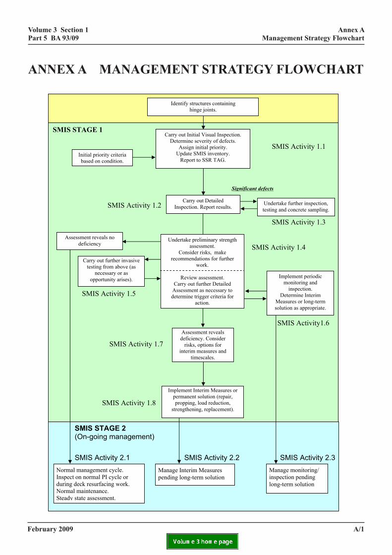
ANNEX A: MANAGEMENT STRATEGY FLOWCHART
SMIS STAGE 1 SMIS Activity 1.1 SMIS Activity 1.2 SMIS Activity 1.3 SMIS Activity 1.4
SMIS Activity 1.5
SMIS Activity1.6
SMIS Activity 1.7 SMIS Activity 1.8
Significant defects
Identify structures containing hinge joints.
Carry out Initial Visual Inspection. Determine severity of defects.
Assign initial priority. Update SMIS inventory.
Report to SSR TAG. Initial priority criteria based on condition.
Assessment reveals deficiency. Consider
risks, options for interim measures and
timescales.
SMIS STAGE 2 (On-going management) SMIS Activity 2.1 SMIS Activity 2.2 SMIS Activity 2.3
Implement periodic monitoring and
inspection. Determine Interim
Measures or long-term solution as appropriate.
Assessment reveals no deficiency
Implement Interim Measures or permanent solution (repair, propping, load reduction,
strengthening, replacement).
Normal management cycle. Inspect on normal PI cycle or during deck resurfacing work. Normal maintenance. Steady state assessment.
Manage Interim Measures pending long-term solution
Manage monitoring/ inspection pending long-term solution
Carry out further invasive testing from above (as
necessary or as opportunity arises).
Undertake preliminary strength assessment.
Consider risks, make recommendations for further
work.
Review assessment. Carry out further Detailed
Assessment as necessary to determine trigger criteria for
action.
Carry out Detailed Inspection. Report results.
Undertake further inspection, testing and concrete sampling.
a/1
annex a management strategy flowchart
february 2009
volume 3 section 1 part 5 ba 93/09
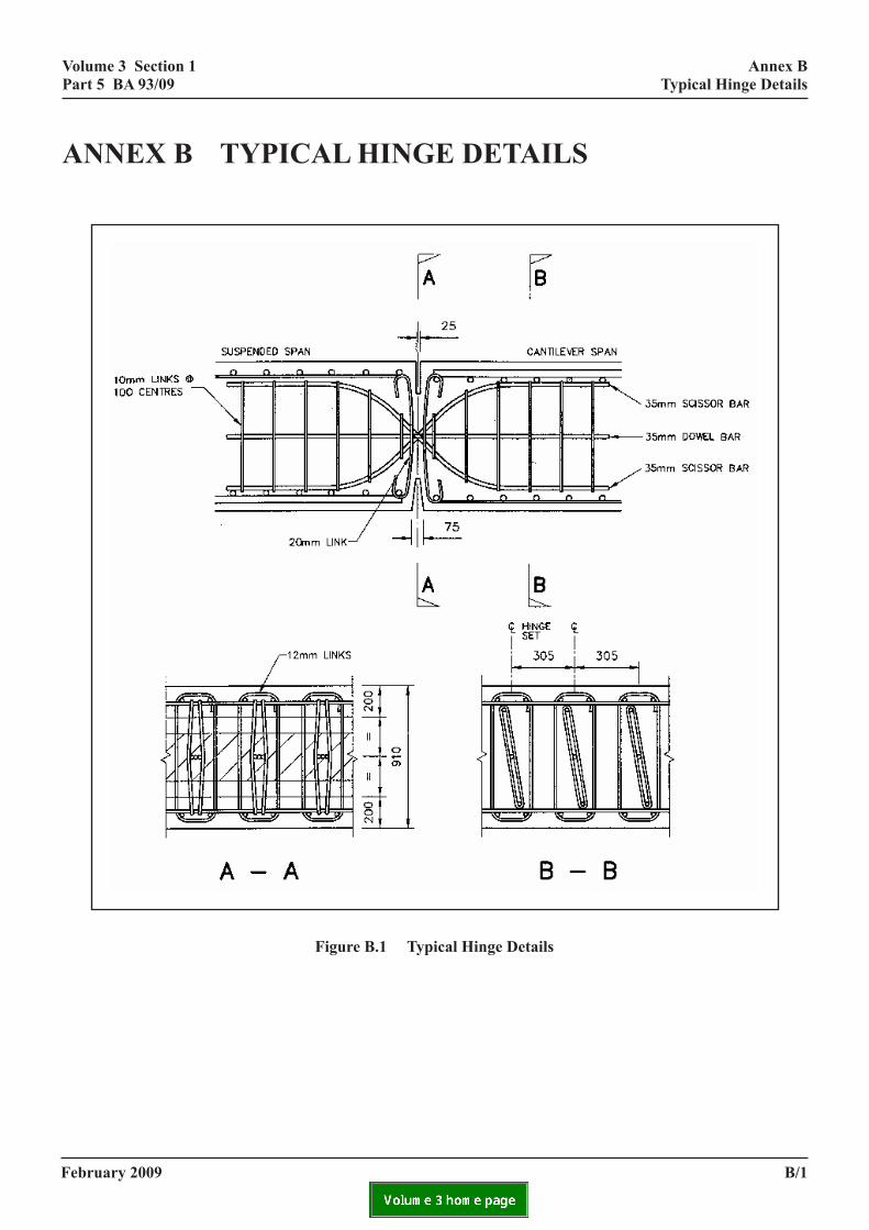
annex b typical hinge details ANNEX B: TYPICAL HINGE DETAILS
b/1
annex b typical hinge details
figure b.1 typical hinge details

february 2009
volume 3 section 1 part 5 ba 93/09
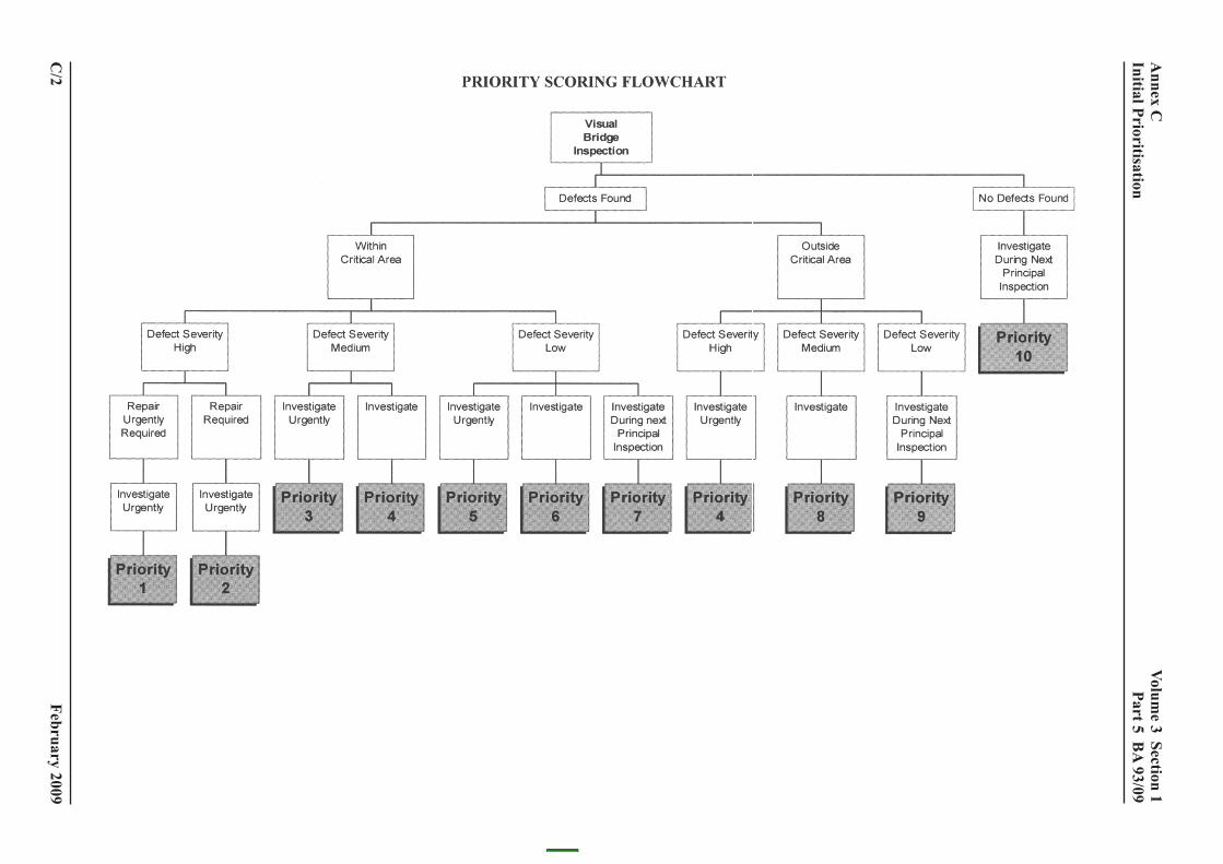
annex c initial prioritisation
C.1 The initial prioritisation presented in the flowchart below is based on the external condition of the hinge. This provides a useful way of allocating resources early in the management programme, which can be modified as further information is obtained. Other factors that need to be considered are:
• other aspects of the inspection/assessment of the structure;
• long-term management strategy for the bridge;
• consideration of current or future road improvement schemes.
c/1
annex c initial prioritisation
february 2009
volume 3 section 1
part 5 ba
93/09
c/2
annex c
initial prioritisation
volume 3 section 1 part 5 ba 93/09
culation
annex d example calculation
annex d example cal
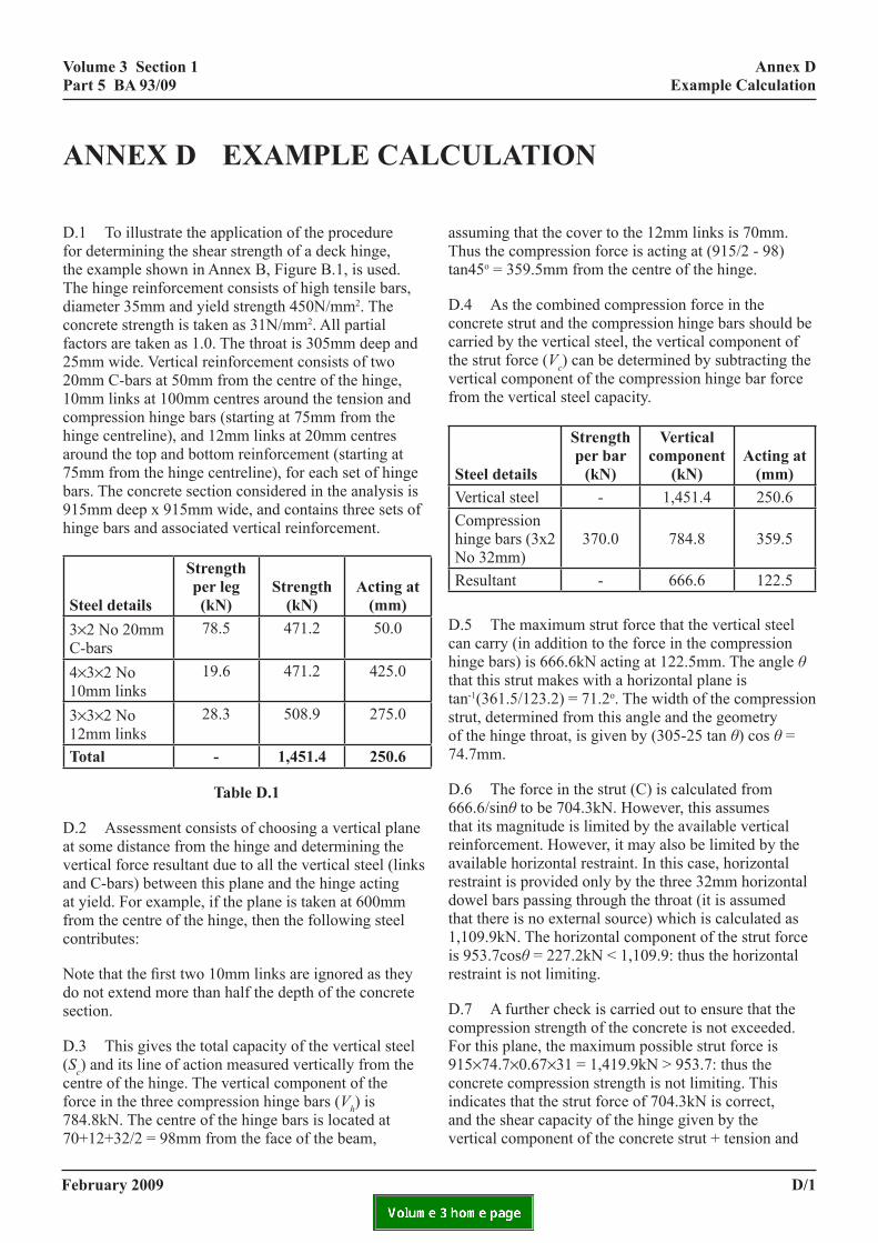
D.1 To illustrate the application of the procedure for determining the shear strength of a deck hinge, the example shown in Annex B, Figure B.1, is used. The hinge reinforcement consists of high tensile bars, diameter 35mm and yield strength 450N/mm2. The concrete strength is taken as 31N/mm2. All partial factors are taken as 1.0. The throat is 305mm deep and 25mm wide. Vertical reinforcement consists of two 20mm C-bars at 50mm from the centre of the hinge, 10mm links at 100mm centres around the tension and compression hinge bars (starting at 75mm from the hinge centreline), and 12mm links at 20mm centres around the top and bottom reinforcement (starting at 75mm from the hinge centreline), for each set of hinge bars. The concrete section considered in the analysis is 915mm deep x 915mm wide, and contains three sets of hinge bars and associated vertical reinforcement.
steel details
strength per leg (kn)
strength (kn)
acting at (mm)
3×2 No 20mm C-bars
78.5 471.2 50.0
4×3×2 No 10mm links
19.6 471.2 425.0
3×3×2 No 12mm links
28.3 508.9 275.0
total - 1,451.4 250.6
table d.1
D.2 Assessment consists of choosing a vertical plane at some distance from the hinge and determining the vertical force resultant due to all the vertical steel (links and C-bars) between this plane and the hinge acting at yield. For example, if the plane is taken at 600mm from the centre of the hinge, then the following steel contributes:
Note that the first two 10mm links are ignored as they do not extend more than half the depth of the concrete section.
D.3 This gives the total capacity of the vertical steel (Sc) and its line of action measured vertically from the centre of the hinge. The vertical component of the force in the three compression hinge bars (Vh) is 784.8kN. The centre of the hinge bars is located at 70+12+32/2 = 98mm from the face of the beam,
february 2009
assuming that the cover to the 12mm links is 70mm. Thus the compression force is acting at (915/2 - 98) tan45o = 359.5mm from the centre of the hinge.
D.4 As the combined compression force in the concrete strut and the compression hinge bars should be carried by the vertical steel, the vertical component of the strut force (Vc) can be determined by subtracting the vertical component of the compression hinge bar force from the vertical steel capacity.
steel details
strength per bar
(kn)
vertical component
(kn)acting at
(mm)Vertical steel - 1,451.4 250.6Compression hinge bars (3x2 No 32mm)
370.0 784.8 359.5
Resultant - 666.6 122.5
D.5 The maximum strut force that the vertical steel can carry (in addition to the force in the compression hinge bars) is 666.6kN acting at 122.5mm. The angle θ that this strut makes with a horizontal plane is tan-1(361.5/123.2) = 71.2o. The width of the compression strut, determined from this angle and the geometry of the hinge throat, is given by (305-25 tan θ) cos θ = 74.7mm.
D.6 The force in the strut (C) is calculated from 666.6/sinθ to be 704.3kN. However, this assumes that its magnitude is limited by the available vertical reinforcement. However, it may also be limited by the available horizontal restraint. In this case, horizontal restraint is provided only by the three 32mm horizontal dowel bars passing through the throat (it is assumed that there is no external source) which is calculated as 1,109.9kN. The horizontal component of the strut force is 953.7cosθ = 227.2kN < 1,109.9: thus the horizontal restraint is not limiting.
D.7 A further check is carried out to ensure that the compression strength of the concrete is not exceeded. For this plane, the maximum possible strut force is 915×74.7×0.67×31 = 1,419.9kN > 953.7: thus the concrete compression strength is not limiting. This indicates that the strut force of 704.3kN is correct, and the shear capacity of the hinge given by the vertical component of the concrete strut + tension and
d/1
volume 3 section 1 part 5 ba 93/09
annex d example calculation
compression hinge bars = 704.3 + 784.8 + 784.8 = 2,236.2kN.
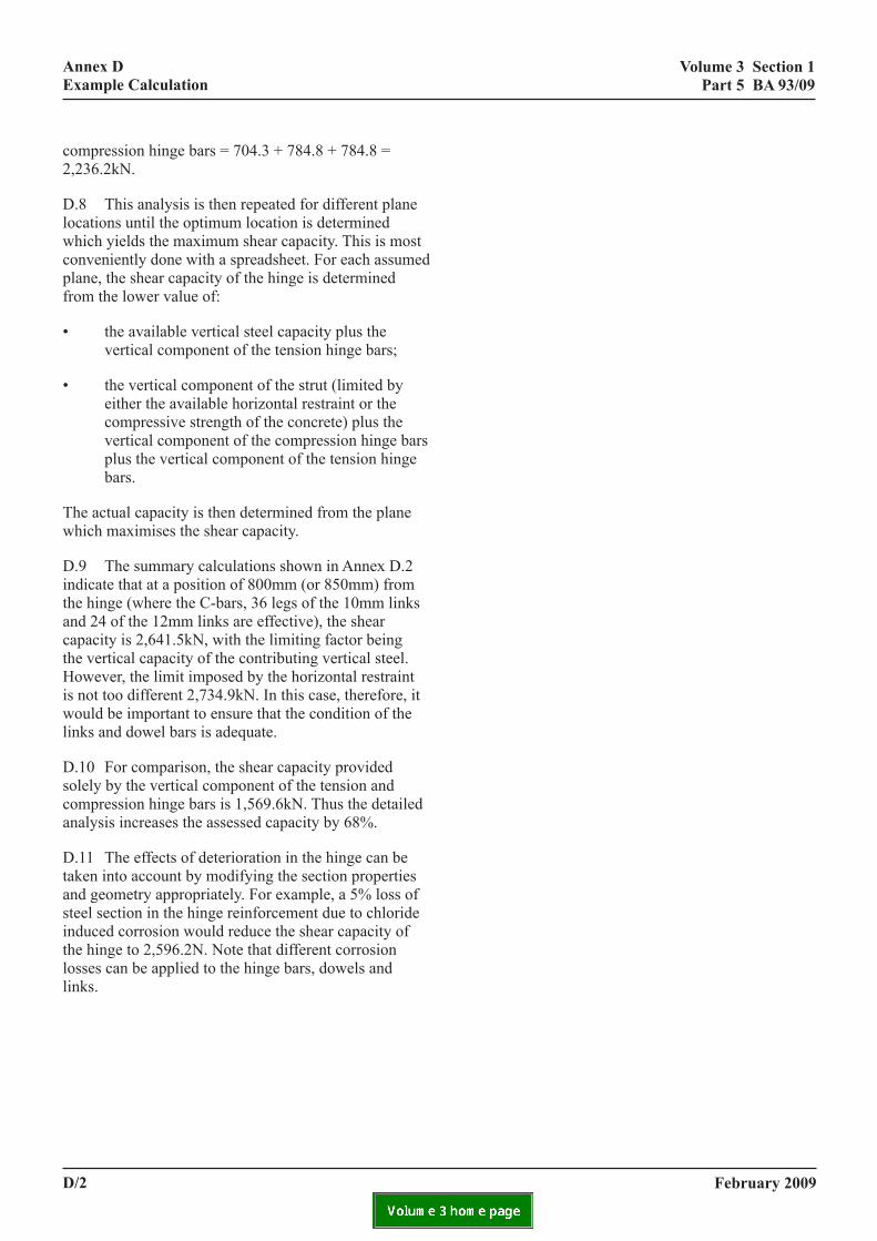
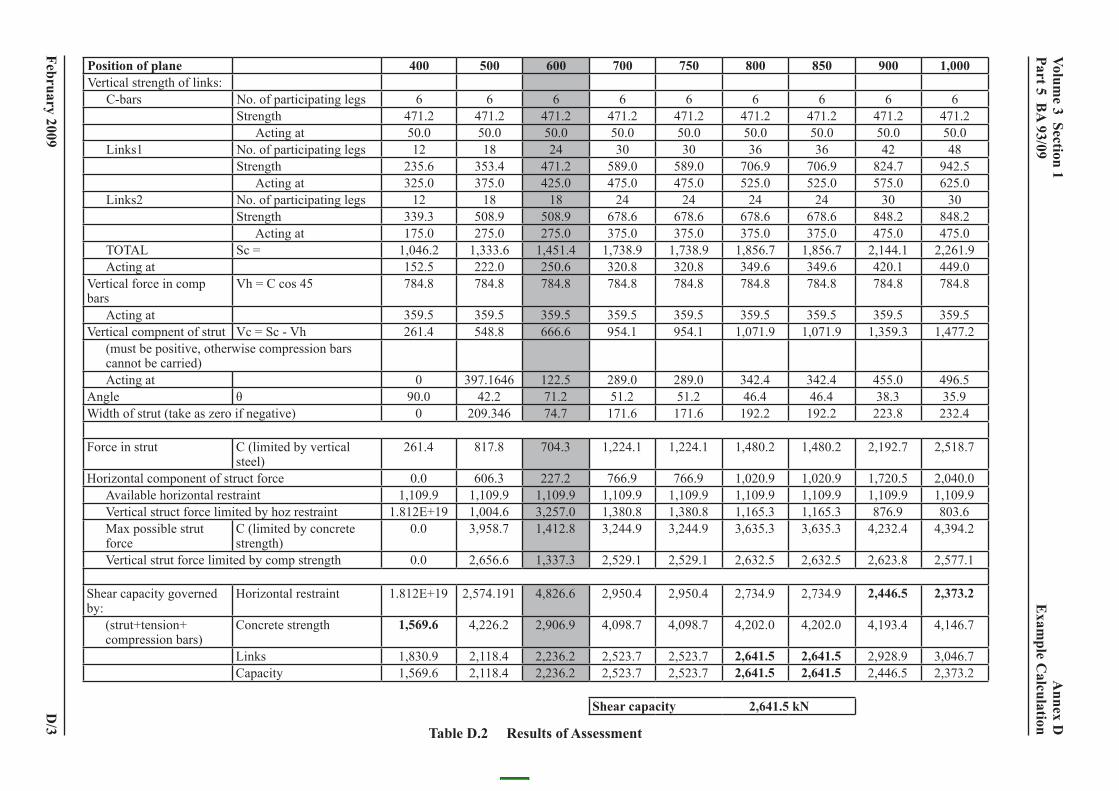
D.8 This analysis is then repeated for different plane locations until the optimum location is determined which yields the maximum shear capacity. This is most conveniently done with a spreadsheet. For each assumed plane, the shear capacity of the hinge is determined from the lower value of:
• the available vertical steel capacity plus the vertical component of the tension hinge bars;
• the vertical component of the strut (limited by either the available horizontal restraint or the compressive strength of the concrete) plus the vertical component of the compression hinge bars plus the vertical component of the tension hinge bars.
The actual capacity is then determined from the plane which maximises the shear capacity.
D.9 The summary calculations shown in Annex D.2 indicate that at a position of 800mm (or 850mm) from the hinge (where the C-bars, 36 legs of the 10mm links and 24 of the 12mm links are effective), the shear capacity is 2,641.5kN, with the limiting factor being the vertical capacity of the contributing vertical steel. However, the limit imposed by the horizontal restraint is not too different 2,734.9kN. In this case, therefore, it would be important to ensure that the condition of the links and dowel bars is adequate.
D.10 For comparison, the shear capacity provided solely by the vertical component of the tension and compression hinge bars is 1,569.6kN. Thus the detailed analysis increases the assessed capacity by 68%.
D.11 The effects of deterioration in the hinge can be taken into account by modifying the section properties and geometry appropriately. For example, a 5% loss of steel section in the hinge reinforcement due to chloride induced corrosion would reduce the shear capacity of the hinge to 2,596.2N. Note that different corrosion losses can be applied to the hinge bars, dowels and
february 2009
links.
d/2
february
volume 3 section 1
part 5 ba
93/09position of plane 400 500 600 700 750 800 850 900 1,000Vertical strength of links: C-bars No. of participating legs 6 6 6 6 6 6 6 6 6
471.2 471.2 471.2 471.250.0 50.0 50.0 50.036 36 42 48
706.9 706.9 824.7 942.5525.0 525.0 575.0 625.0
24 24 30 30678.6 678.6 848.2 848.2375.0 375.0 475.0 475.0
1,856.7 1,856.7 2,144.1 2,261.9349.6 349.6 420.1 449.0784.8 784.8 784.8 784.8
359.5 359.5 359.5 359.51,071.9 1,071.9 1,359.3 1,477.2
342.4 342.4 455.0 496.546.4 46.4 38.3 35.9
192.2 192.2 223.8 232.4
1,480.2 1,480.2 2,192.7 2,518.7
1,020.9 1,020.9 1,720.5 2,040.01,109.9 1,109.9 1,109.9 1,109.91,165.3 1,165.3 876.9 803.63,635.3 3,635.3 4,232.4 4,394.2
2,632.5 2,632.5 2,623.8 2,577.1
2,734.9 2,734.9 2,446.5 2,373.2
4,202.0 4,202.0 4,193.4 4,146.7
2,641.5 2,641.5 2,928.9 3,046.72,641.5 2,641.5 2,446.5 2,373.2
2,641.5 kn
annex d
e
xample c
alculation
2009
Strength 471.2 471.2 471.2 471.2 471.2 Acting at 50.0 50.0 50.0 50.0 50.0
Links1 No. of participating legs 12 18 24 30 30Strength 235.6 353.4 471.2 589.0 589.0 Acting at 325.0 375.0 425.0 475.0 475.0
Links2 No. of participating legs 12 18 18 24 24Strength 339.3 508.9 508.9 678.6 678.6 Acting at 175.0 275.0 275.0 375.0 375.0
TOTAL Sc = 1,046.2 1,333.6 1,451.4 1,738.9 1,738.9 Acting at 152.5 222.0 250.6 320.8 320.8Vertical force in comp bars
Vh = C cos 45 784.8 784.8 784.8 784.8 784.8
Acting at 359.5 359.5 359.5 359.5 359.5Vertical compnent of strut Vc = Sc - Vh 261.4 548.8 666.6 954.1 954.1 (must be positive, otherwise compression bars cannot be carried) Acting at 0 397.1646 122.5 289.0 289.0Angle θ 90.0 42.2 71.2 51.2 51.2Width of strut (take as zero if negative) 0 209.346 74.7 171.6 171.6
Force in strut C (limited by vertical steel)
261.4 817.8 704.3 1,224.1 1,224.1
Horizontal component of struct force 0.0 606.3 227.2 766.9 766.9 Available horizontal restraint 1,109.9 1,109.9 1,109.9 1,109.9 1,109.9 Vertical struct force limited by hoz restraint 1.812E+19 1,004.6 3,257.0 1,380.8 1,380.8 Max possible strut force
C (limited by concrete strength)
0.0 3,958.7 1,412.8 3,244.9 3,244.9
Vertical strut force limited by comp strength 0.0 2,656.6 1,337.3 2,529.1 2,529.1
Shear capacity governed by:
Horizontal restraint 1.812E+19 2,574.191 4,826.6 2,950.4 2,950.4
(strut+tension+ compression bars)
Concrete strength 1,569.6 4,226.2 2,906.9 4,098.7 4,098.7
Links 1,830.9 2,118.4 2,236.2 2,523.7 2,523.7Capacity 1,569.6 2,118.4 2,236.2 2,523.7 2,523.7
shear capacity
table d.2 results of assessment
d/3

volume 3 section 1 part 5 ba 93/09
ency smis s
annex e highways agency smis requirements
annex e highways ag requirement
e.1 introduction
E1.1 This Annex provides guidance on how to use Structures Management Information System (SMIS) when inputting data or viewing progress reports for the hinge deck strategy. It gives a summary of what is required by SMIS for each activity in the flowchart in Annex A.
E1.2 This Annex is primarily aimed at those who will be inputting data and it assumes a working knowledge of SMIS. The screens used adopt the general use and format of other screens in SMIS. Hence detailed instructions of how to log on, and how to use the screens are not included here. Instead, the Annex refers to the relevant part of the online user guide. The SMIS user is recommended to read through this annex in conjunction with Annex A, and the relevant parts of the SMIS online guide before embarking on using the system to input data.
E1.3 For those who have an interest in the progress of the programme, your attention is drawn to the Progress Reporting paragraph in E.2 below.
e.2 general
Background
E2.1 SMIS is a tool for managing the Highways Agency (HA) structures asset. One component of the system provides a means to capture data and organise a series of actions for programmes that are beyond the usual scope of structures renewals work. The hinge deck programme is one such example, where each structure within the programme goes through a series of steps in order to establish what needs to be done in a coordinated manner. The series of steps are given in Annex A.
E2.2 The reasons for such an approach is to ensure that a consistent method is adopted for problems across the network, and that the data is stored centrally so that an overview of the problem can be easily gained.
E2.3 SMIS uses the term National Structures Programme (NSP) to describe these programmes of work.
february 2009
Contacts
E2.4 If experiencing difficulties, use the following channels of support:
• BIS ServiceDirect, for support for accessing the system: contact on 0113 254 1140 or email [email protected].
• The SMIS administrator, for support in using the system and queries on the data: contact by email on [email protected].
• Queries specific to the hinge deck programme should be referred to your HA TAG office.
Progress Reporting
E2.5 Several reports are available. They can be accessed using the NSP reports icon, which is found by clicking on the Programmes menu.
• structures by stage report. This shows a summary snapshot, giving the numbers of structures that are currently in each stage of the programme. A further breakdown of each activity in each stage is given in the Current Progression Report.
• current progression report. This gives a detailed view, showing the current position of structures for each activity in the programme. It shows the current position for those activities that are not completed.
• programme activity report. This shows a history of activities that have been assigned to structures, whether currently outstanding or completed. It shows the dates of when each activity was ‘created’ in the system and when it was completed.
• structures added report. This shows the pattern of how structures have been added to the programme over time.
e/1
volume 3 section 1 part 5 ba 93/09
annex e highways agency smis requirements
Reviewing Outstanding Activities
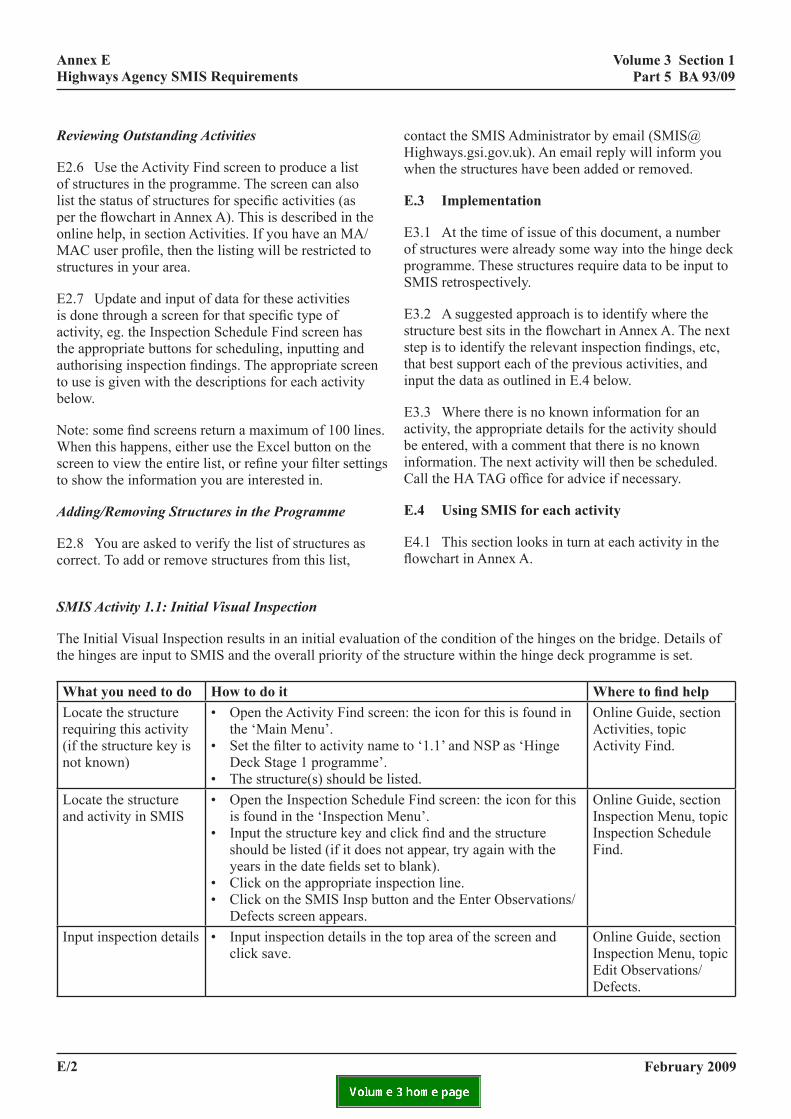
E2.6 Use the Activity Find screen to produce a list of structures in the programme. The screen can also list the status of structures for specific activities (as per the flowchart in Annex A). This is described in the online help, in section Activities. If you have an MA/MAC user profile, then the listing will be restricted to structures in your area.
E2.7 Update and input of data for these activities is done through a screen for that specific type of activity, eg. the Inspection Schedule Find screen has the appropriate buttons for scheduling, inputting and authorising inspection findings. The appropriate screen to use is given with the descriptions for each activity below.
Note: some find screens return a maximum of 100 lines.When this happens, either use the Excel button on the screen to view the entire list, or refine your filter settingsto show the information you are interested in.
Adding/Removing Structures in the Programme
E2.8 You are asked to verify the list of structures as correct. To add or remove structures from this list,
SMIS Activity 1.1: Initial Visual Inspection
The Initial Visual Inspection results in an initial evaluatithe hinges are input to SMIS and the overall priority of t
what you need to do how to do itLocate the structure requiring this activity (if the structure key is not known)
• Open the Activity Find scrthe ‘Main Menu’.
• Set the filter to activity namDeck Stage 1 programme’
• The structure(s) should be Locate the structure and activity in SMIS
• Open the Inspection Schedis found in the ‘Inspection
• Input the structure key andshould be listed (if it does years in the date fields set
• Click on the appropriate in• Click on the SMIS Insp bu
Defects screen appears.Input inspection details • Input inspection details in
click save.
e/2
contact the SMIS Administrator by email ([email protected]). An email reply will inform you when the structures have been added or removed.
e.3 implementation
E3.1 At the time of issue of this document, a number of structures were already some way into the hinge deck programme. These structures require data to be input to SMIS retrospectively.
E3.2 A suggested approach is to identify where the structure best sits in the flowchart in Annex A. The next step is to identify the relevant inspection findings, etc, that best support each of the previous activities, and input the data as outlined in E.4 below.
E3.3 Where there is no known information for an activity, the appropriate details for the activity should be entered, with a comment that there is no known information. The next activity will then be scheduled. Call the HA TAG office for advice if necessary.
e.4 using smis for each activity
E4.1 This section looks in turn at each activity in the flowchart in Annex A.
on of the condition of the hinges on the bridge. Details of he structure within the hinge deck programme is set.
Where to find helpeen: the icon for this is found in
e to ‘1.1’ and NSP as ‘Hinge .listed.
Online Guide, section Activities, topic Activity Find.
ule Find screen: the icon for this Menu’. click find and the structure not appear, try again with the to blank).spection line.tton and the Enter Observations/
Online Guide, section Inspection Menu, topic Inspection Schedule Find.
the top area of the screen and Online Guide, section Inspection Menu, topic Edit Observations/Defects.
february 2009
volume 3 section 1 part 5 ba 93/09
annex e highways agency smis requirements
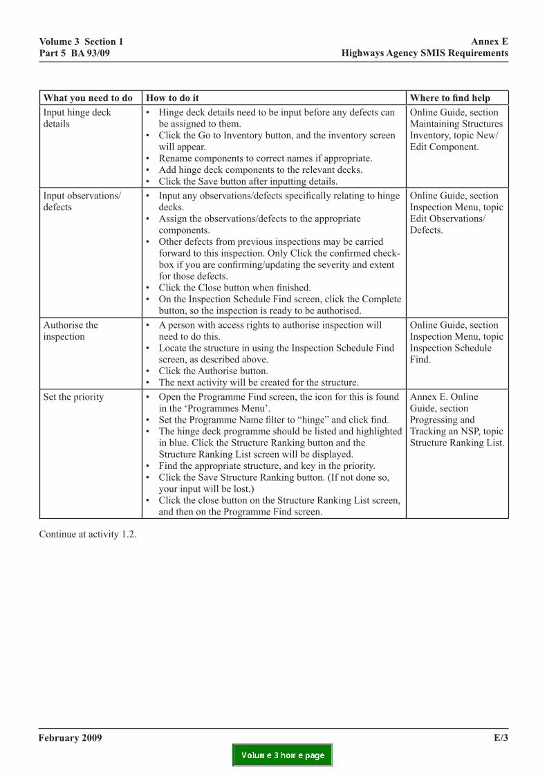
what you need to do how to do it Where to find helpInput hinge deck details
• Hinge deck details need to be input before any defects can be assigned to them.
• Click the Go to Inventory button, and the inventory screen will appear.
• Rename components to correct names if appropriate.• Add hinge deck components to the relevant decks.• Click the Save button after inputting details.
Online Guide, section Maintaining Structures Inventory, topic New/Edit Component.
Input observations/defects
• Input any observations/defects specifically relating to hinge decks.
• Assign the observations/defects to the appropriate components.
• Other defects from previous inspections may be carried forward to this inspection. Only Click the confirmed check-box if you are confirming/updating the severity and extent for those defects.
• Click the Close button when finished.• On the Inspection Schedule Find screen, click the Complete
button, so the inspection is ready to be authorised.
Online Guide, section Inspection Menu, topic Edit Observations/Defects.
Authorise the inspection
• A person with access rights to authorise inspection will need to do this.
• Locate the structure in using the Inspection Schedule Find screen, as described above.
• Click the Authorise button.• The next activity will be created for the structure.
Online Guide, section Inspection Menu, topic Inspection Schedule Find.
Set the priority • Open the Programme Find screen, the icon for this is found in the ‘Programmes Menu’.
• Set the Programme Name filter to “hinge” and click find.• The hinge deck programme should be listed and highlighted
in blue. Click the Structure Ranking button and the Structure Ranking List screen will be displayed.
• Find the appropriate structure, and key in the priority.• Click the Save Structure Ranking button. (If not done so,
your input will be lost.)• Click the close button on the Structure Ranking List screen,
and then on the Programme Find screen.
Annex E. Online Guide, section Progressing and Tracking an NSP, topic Structure Ranking List.
Continue at activity 1.2.
february 2009 e/3

volume 3 section 1 part 5 ba 93/09
annex e highways agency smis requirements
SMIS Activity 1.2: Detailed Inspection
This Inspection is to determine the crack width and extent of seepage.
The target date for this may depend on the priority set and other access opportunities, and the agent may prefer to set an appropriate target date to assist with inspection planning (see the Online Guide, section Inspection Menu, topic Set Target Date).
what you need to do how to do it Where to find helpLocate the structure requiring this activity (if the structure key is not known)
• Open the Activity Find screen: the icon for this is found in the ‘Main Menu’.
• Set the filter to activity name to ‘1.2’ and NSP as ‘Hinge Deck Stage 1 programme’.
• The structure(s) should be listed.
Online Guide, section Activities, topic Activity Find.
Locate the structure and activity in SMIS
• Open the Inspection Schedule Find screen: the icon for this is found in the ‘Inspection Menu’.
• Input the structure key and click find and the structure should be listed.
• Click on the appropriate inspection line.• Click on the SMIS Insp button and the Enter Observations/
Defects screen appears.
Online Guide, section Inspection Menu, topic Inspection Schedule Find.
Input inspection details • Input inspection details in the top area of the screen and click save.
• Add or update observations as appropriate for the crack width and seepage (note measurements may be recorded in the comments field).
• Other defects from previous inspections may be carried forward to this inspection. Only Click the confirmed check-box if you are confirming/updating the severity and extent for those defects.
• Click the Close button when finished.• On the Inspection Schedule Find screen, click the Complete
button, so the inspection is ready to be authorised.
Online Guide, section Inspection Menu, topic Edit Observations/Defects.
Authorise the inspection
• A person with access rights to authorise inspection will need to do this.
• Locate the structure in using the Inspection Schedule Find screen, as described above.
• Click the Authorise button.
Online Guide, section Inspection Menu, topic Inspection Schedule Find.
Choose the branch in the flowchart
• As the activity is set to complete, you will be asked which activity is to follow.
• Select step 1.3 or 2.1 as appropriate.• DO NOT select both steps.• The next activity will be created for the structure.
Online Guide, section Progressing and Tracking an NSP, topic Choose Next Activities. (Note an incorrect choice can be corrected – see Online Guide, section Activities before proceeding further.)
If activity 1.3 was selected, then continue with activity 1.3 below.
If activity 2.1 was selected, then no further action is required until the future management strategy is issued.
february 2009e/4
volume 3 section 1 part 5 ba 93/09
annex e highways agency smis requirements
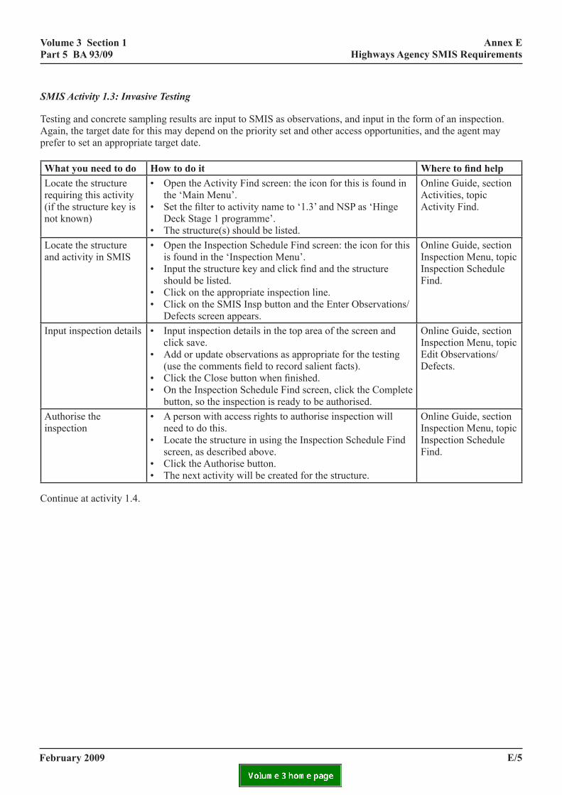
SMIS Activity 1.3: Invasive Testing
Testing and concrete sampling results are input to SMIS as observations, and input in the form of an inspection. Again, the target date for this may depend on the priority set and other access opportunities, and the agent may prefer to set an appropriate target date.
what you need to do how to do it Where to find helpLocate the structure requiring this activity (if the structure key is not known)
• Open the Activity Find screen: the icon for this is found in the ‘Main Menu’.
• Set the filter to activity name to ‘1.3’ and NSP as ‘Hinge Deck Stage 1 programme’.
• The structure(s) should be listed.
Online Guide, section Activities, topic Activity Find.
Locate the structure and activity in SMIS
• Open the Inspection Schedule Find screen: the icon for this is found in the ‘Inspection Menu’.
• Input the structure key and click find and the structure should be listed.
• Click on the appropriate inspection line.• Click on the SMIS Insp button and the Enter Observations/
Defects screen appears.
Online Guide, section Inspection Menu, topic Inspection Schedule Find.
Input inspection details • Input inspection details in the top area of the screen and click save.
• Add or update observations as appropriate for the testing (use the comments field to record salient facts).
• Click the Close button when finished.• On the Inspection Schedule Find screen, click the Complete
button, so the inspection is ready to be authorised.
Online Guide, section Inspection Menu, topic Edit Observations/Defects.
Authorise the inspection
• A person with access rights to authorise inspection will need to do this.
• Locate the structure in using the Inspection Schedule Find screen, as described above.
• Click the Authorise button.• The next activity will be created for the structure.
Online Guide, section Inspection Menu, topic Inspection Schedule Find.
Continue at activity 1.4.
february 2009 e/5
volume 3 section 1 part 5 ba 93/09
annex e highways agency smis requirements
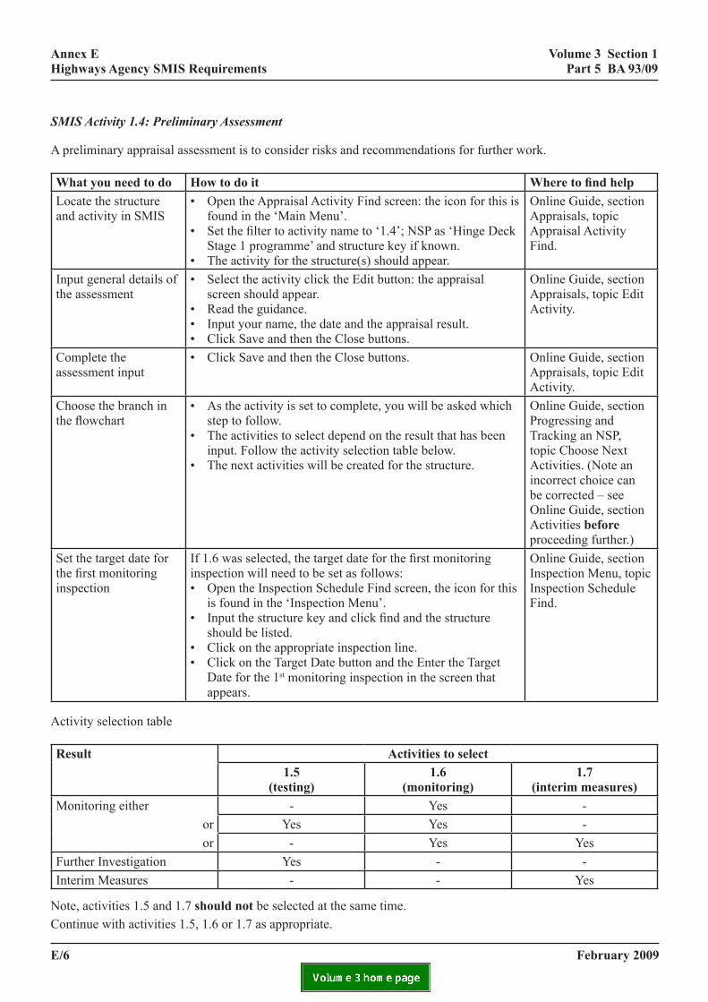
SMIS Activity 1.4: Preliminary Assessment
A preliminary appraisal assessment is to consider risks and recommendations for further work.
what you need to do how to do it Where to find helpLocate the structure and activity in SMIS
• Open the Appraisal Activity Find screen: the icon for this is found in the ‘Main Menu’.
• Set the filter to activity name to ‘1.4’; NSP as ‘Hinge Deck Stage 1 programme’ and structure key if known.
• The activity for the structure(s) should appear.
Online Guide, section Appraisals, topic Appraisal Activity Find.
Input general details of the assessment
• Select the activity click the Edit button: the appraisal screen should appear.
• Read the guidance.• Input your name, the date and the appraisal result.• Click Save and then the Close buttons.
Online Guide, section Appraisals, topic Edit Activity.
Complete the assessment input
• Click Save and then the Close buttons. Online Guide, section Appraisals, topic Edit Activity.
Choose the branch in the flowchart
• As the activity is set to complete, you will be asked which step to follow.
• The activities to select depend on the result that has been input. Follow the activity selection table below.
• The next activities will be created for the structure.
Online Guide, section Progressing and Tracking an NSP, topic Choose Next Activities. (Note an incorrect choice can be corrected – see Online Guide, section Activities before proceeding further.)
Set the target date for the first monitoring inspection
If 1.6 was selected, the target date for the first monitoring inspection will need to be set as follows:• Open the Inspection Schedule Find screen, the icon for this
is found in the ‘Inspection Menu’.• Input the structure key and click find and the structure
should be listed.• Click on the appropriate inspection line.• Click on the Target Date button and the Enter the Target
Date for the 1st monitoring inspection in the screen that appears.
Online Guide, section Inspection Menu, topic Inspection Schedule Find.
Activity selection table
result activities to select1.5
(testing)1.6
(monitoring)1.7
(interim measures) Monitoring either - Yes -
or Yes Yes -or - Yes Yes
Further Investigation Yes - -Interim Measures - - Yes
Note, activities 1.5 and 1.7 should not be selected at the same time.Continue with activities 1.5, 1.6 or 1.7 as appropriate.
february 2009e/6
volume 3 section 1 part 5 ba 93/09
annex e highways agency smis requirements
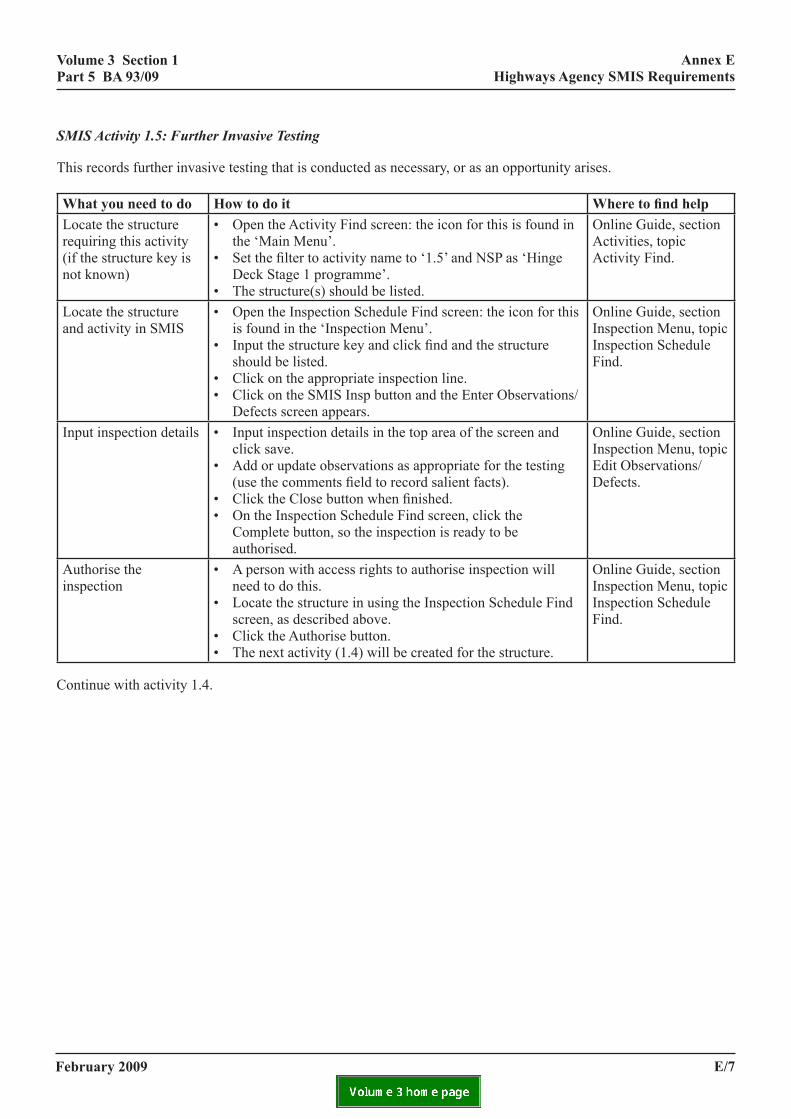
SMIS Activity 1.5: Further Invasive Testing
This records further invasive testing that is conducted as necessary, or as an opportunity arises.
what you need to do how to do it Where to find helpLocate the structure requiring this activity (if the structure key is not known)
• Open the Activity Find screen: the icon for this is found in the ‘Main Menu’.
• Set the filter to activity name to ‘1.5’ and NSP as ‘Hinge Deck Stage 1 programme’.
• The structure(s) should be listed.
Online Guide, section Activities, topic Activity Find.
Locate the structure and activity in SMIS
• Open the Inspection Schedule Find screen: the icon for this is found in the ‘Inspection Menu’.
• Input the structure key and click find and the structure should be listed.
• Click on the appropriate inspection line.• Click on the SMIS Insp button and the Enter Observations/
Defects screen appears.
Online Guide, section Inspection Menu, topic Inspection Schedule Find.
Input inspection details • Input inspection details in the top area of the screen and click save.
• Add or update observations as appropriate for the testing (use the comments field to record salient facts).
• Click the Close button when finished.• On the Inspection Schedule Find screen, click the
Complete button, so the inspection is ready to be authorised.
Online Guide, section Inspection Menu, topic Edit Observations/Defects.
Authorise the inspection
• A person with access rights to authorise inspection will need to do this.
• Locate the structure in using the Inspection Schedule Find screen, as described above.
• Click the Authorise button.• The next activity (1.4) will be created for the structure.
Online Guide, section Inspection Menu, topic Inspection Schedule Find.
Continue with activity 1.4.
february 2009 e/7

volume 3 section 1 part 5 ba 93/09
annex e highways agency smis requirements
SMIS Activity 1.6: Monitoring
If periodic monitoring and inspections are required, a record of each monitoring ‘visit’ or inspection is recorded in SMIS.
what you need to do how to do it Where to find helpLocate the structure and activity in SMIS
• Open the Inspection Schedule Find screen: the icon for this is found in the ‘Inspection Menu’.
• Input the structure key (if known), and/or Inspection Type of Monitoring. Click find and the structure should be listed.
• Click on the appropriate inspection line.• Click on the SMIS Insp button and the Enter Observations/
Defects screen appears.
Online Guide, section Inspection Menu, topic Inspection Schedule Find.
Input inspection details • Input inspection details in the top area of the screen and click save.
• Add or update observations as appropriate for the observation/defect being monitored (note measurements may be recorded in the comments field).
• Click the Close button when finished.• On the Inspection Schedule Find screen, click the
Complete button, so the inspection is ready to be authorised.
Online Guide, section Inspection Menu, topic Edit Observations/Defects.
Authorise the inspection
• A person with access rights to authorise inspection will need to do this.
• Locate the structure in using the Inspection Schedule Find screen, as described above.
• Click the Authorise button.
Online Guide, section Inspection Menu, topic Inspection Schedule Find.
Set the target date for the next monitoring inspection
• The Schedule Monitoring window will appear, complete the details and press the Save or End Monitoring buttons as appropriate.
Online Guide, section Monitoring, topic Schedule Monitoring.
Choose the branch in the flowchart
• The Choose next Activity window will now appear.• If the Save was clicked on the previous window, a further
monitoring inspection will have been scheduled. In this case, select option 1.4 if the monitoring has resulted in further consideration being needed. DO NOT select 2.3.
• If the End Monitoring was clicked on the previous window, no further monitoring inspection will have been scheduled. In this case, select option 1.4 or 2.3 as appropriate. DO NOT select both steps.
• The next activity will be created for the structure.
Online Guide, section Progressing and Tracking an NSP, topic Choose Next Activities. (Note an incorrect choice can be corrected – see Online Guide, section Activities before proceeding further.)
Continue with further monitoring (activity 1.6) and/or a further interim appraisal (activity 1.4) as appropriate.
If activity 2.3 is selected, then no further action is required and the normal management (inspection and maintenance) cycle is followed.
february 2009e/8
volume 3 section 1 part 5 ba 93/09
annex e highways agency smis requirements
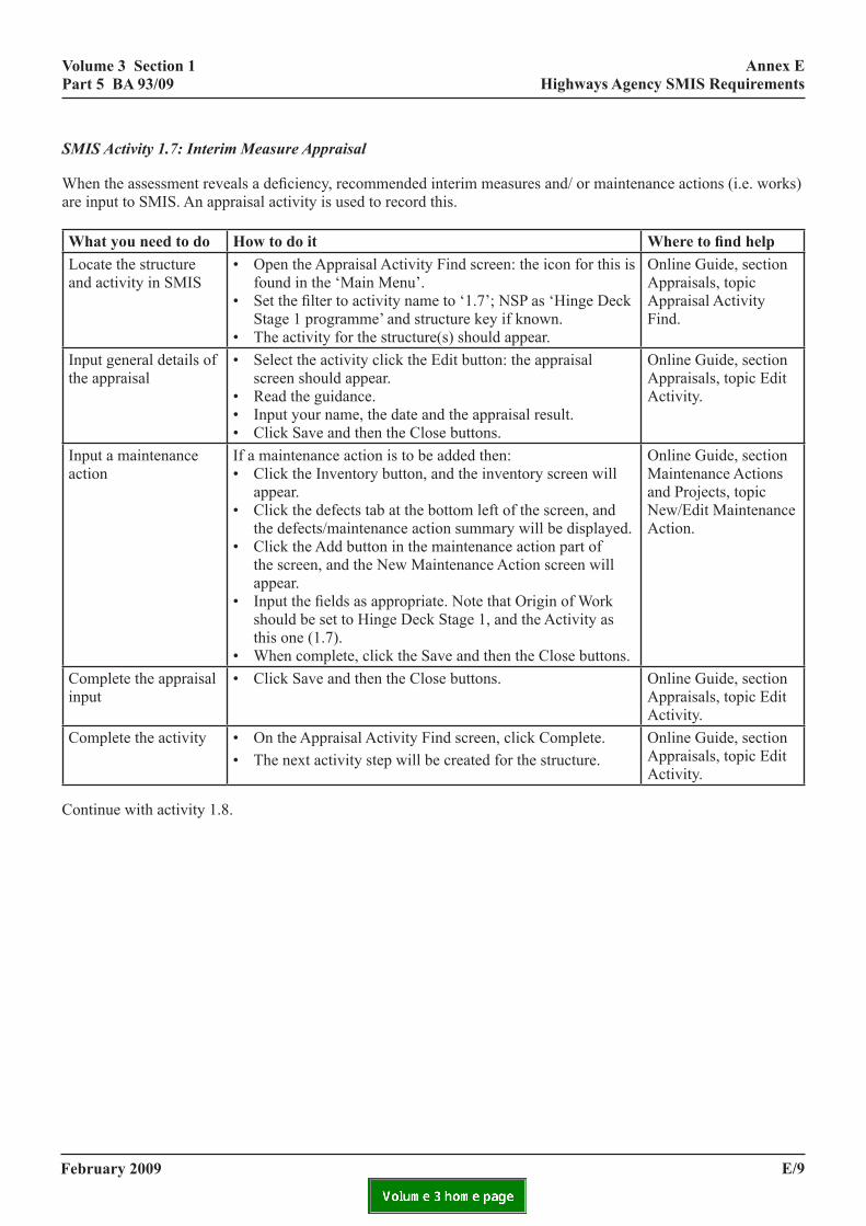
SMIS Activity 1.7: Interim Measure Appraisal
When the assessment reveals a deficiency, recommended interim measures and/ or maintenance actions (i.e. works) are input to SMIS. An appraisal activity is used to record this.
what you need to do how to do it Where to find helpLocate the structure and activity in SMIS
• Open the Appraisal Activity Find screen: the icon for this is found in the ‘Main Menu’.
• Set the filter to activity name to ‘1.7’; NSP as ‘Hinge Deck Stage 1 programme’ and structure key if known.
• The activity for the structure(s) should appear.
Online Guide, section Appraisals, topic Appraisal Activity Find.
Input general details of the appraisal
• Select the activity click the Edit button: the appraisal screen should appear.
• Read the guidance.• Input your name, the date and the appraisal result.• Click Save and then the Close buttons.
Online Guide, section Appraisals, topic Edit Activity.
Input a maintenance action
If a maintenance action is to be added then:• Click the Inventory button, and the inventory screen will
appear.• Click the defects tab at the bottom left of the screen, and
the defects/maintenance action summary will be displayed.• Click the Add button in the maintenance action part of
the screen, and the New Maintenance Action screen will appear.
• Input the fields as appropriate. Note that Origin of Work should be set to Hinge Deck Stage 1, and the Activity as this one (1.7).
• When complete, click the Save and then the Close buttons.
Online Guide, section Maintenance Actions and Projects, topic New/Edit Maintenance Action.
Complete the appraisal input
• Click Save and then the Close buttons. Online Guide, section Appraisals, topic Edit Activity.
Complete the activity • On the Appraisal Activity Find screen, click Complete.• The next activity step will be created for the structure.
Online Guide, section Appraisals, topic Edit Activity.
Continue with activity 1.8.
february 2009 e/9

volume 3 section 1 part 5 ba 93/09
annex e highways agency smis requirements
e
SMIS Activity 1.8: Confirm Interim Measure is Implemented
This is to confirm that an interim measure or maintenance action has been implemented. There may be instances were an interim measure is put in place until the maintenance action is complete. In such cases, the interim measurbeing implemented is recorded against this activity.
what you need to do how to do it Where to find helpLocate the structure requiring this activity (if the structure key is not known)
• Open the Activity Find screen, the icon for this is found in the ‘Main Menu’.
• Set the filter to activity name to ‘1.8’ and NSP as ‘Hinge Deck Stage 1 programme’.
• The structure(s) should be listed.
Online Guide, section Activities, topic Activity Find.
Locate the structure • Open the Structure Find screen, the icon for this is found in the ‘Main Menu’.
• Input the structure key and click find and the structure should be listed.
• Click Inventory and the structure details should be shown.
Online Guide, section Maintaining StructuresInventory, topic Structure Find.
Confirm an interim measure or maintenance action has been implemented
• Click Open Event and the New Event window will appear.• Complete the fields in the window and be sure to check the
‘1.8’ activity in the list at the bottom.• Then click Open New Event.
Online Guide, section Maintaining StructuresInventory, topic New Event.
Input an interim measure
If an interim measure has been implemented:• Click the appropriate part of the component hierarchy
of where the interim measure has been put in place (e.g. bridge, span or structural joint).
• Click the Add button and select an interim measure.• Complete the details for the interim measure and then click
the Save button.
Online Guide, section Maintaining StructuresInventory, topic New/Edit Component.
Reviewing interim measures
• The agent is to ensure that interim measures are reviewed and updated in SMIS when they have exceeded their expected end date.
The Main Menu, icon Interim Measures Find allows interim measures that have expired to be located. Set the End Date, To field to today and clickthe Find button.
Complete the activity • Click Close Event. The system will validate and save your updates. (Note the checking the 1.8 activity on the Open Event is an update that is saved at this point.)
Online Guide, section Maintaining StructuresInventory, topic Inventory – Event Status Open.
february 2009e/10

volume 3 section 1 part 5 ba 93/09
annex e highways agency smis requirements
what you need to do how to do it Where to find helpComplete a maintenance action
If a maintenance action has been completed:• Open the Project Find screen, the icon for this is found in
the ‘Projects Menu’.• Find and select the appropriate project using this screen,
and click the Open button. (If the project name is not known, this can be found in the inventory details for the structure as described above, and clicking on the Projects item, when all projects associated with the structure will be listed.)
• Click the Set as Complete button.• Confirm which maintenance actions in the project have
been completed and click the Close button.
Online Guide, section Link to HAMIS for Bidding and Doing Works, topic Complete Project.
No further activity related input is required until the future management strategy is issued.
However monitoring (activity 1.6) continues if applicable, and maintenance actions are set as completed as and when projects are completed.
february 2009 e/11
volume 3 section 1 part 5 ba 93/09
nt
annex f risk assessment
annex f risk assessme
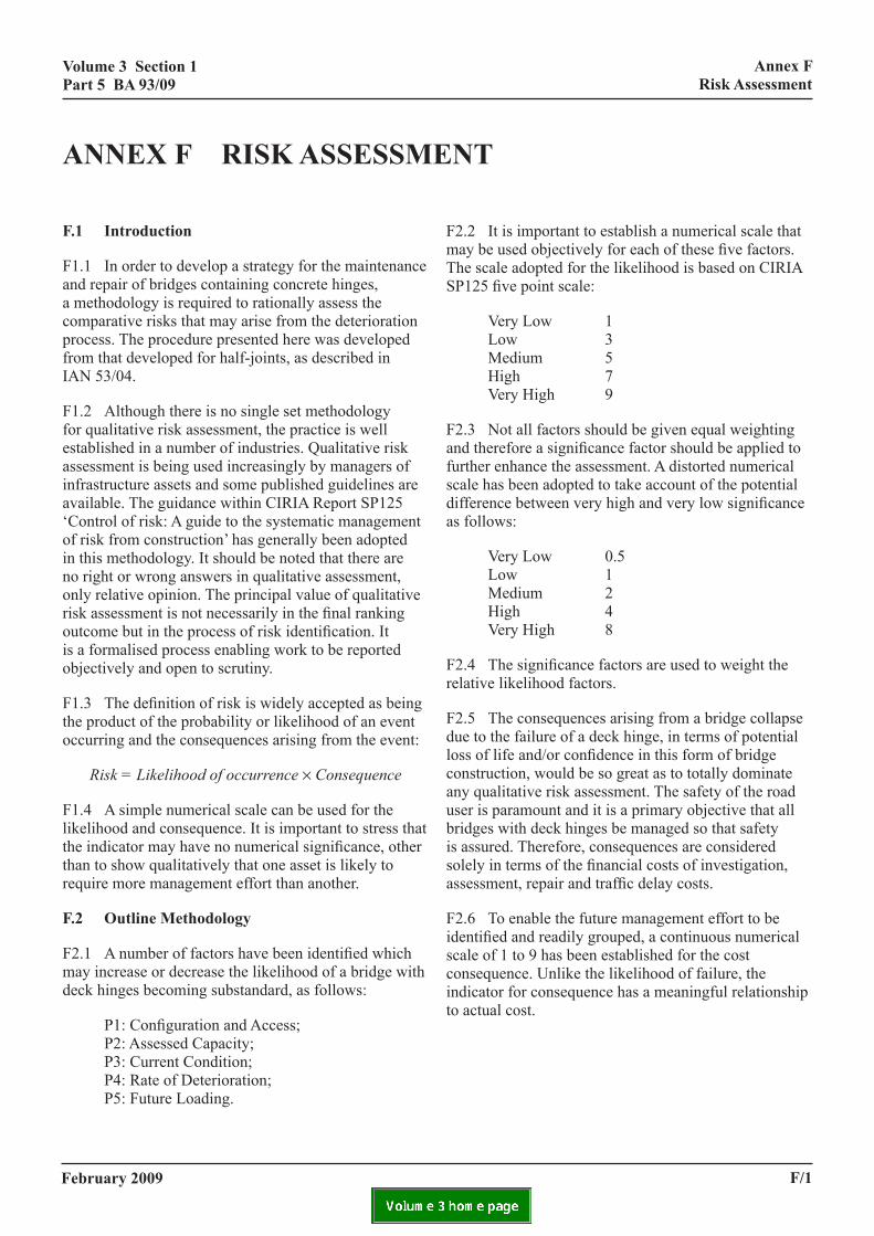
f.1 introduction
F1.1 In order to develop a strategy for the maintenance and repair of bridges containing concrete hinges, a methodology is required to rationally assess the comparative risks that may arise from the deterioration process. The procedure presented here was developed from that developed for half-joints, as described in IAN 53/04.
F1.2 Although there is no single set methodology for qualitative risk assessment, the practice is well established in a number of industries. Qualitative risk assessment is being used increasingly by managers of infrastructure assets and some published guidelines are available. The guidance within CIRIA Report SP125 ‘Control of risk: A guide to the systematic management of risk from construction’ has generally been adopted in this methodology. It should be noted that there are no right or wrong answers in qualitative assessment, only relative opinion. The principal value of qualitative risk assessment is not necessarily in the final ranking outcome but in the process of risk identification. It is a formalised process enabling work to be reported objectively and open to scrutiny.
F1.3 The definition of risk is widely accepted as being the product of the probability or likelihood of an event occurring and the consequences arising from the event:
Risk = Likelihood of occurrence × Consequence
F1.4 A simple numerical scale can be used for the likelihood and consequence. It is important to stress that the indicator may have no numerical significance, other than to show qualitatively that one asset is likely to require more management effort than another.
f.2 outline methodology
F2.1 A number of factors have been identified which may increase or decrease the likelihood of a bridge with deck hinges becoming substandard, as follows:
P1: Configuration and Access; P2: Assessed Capacity; P3: Current Condition; P4: Rate of Deterioration; P5: Future Loading.
february 2009
F2.2 It is important to establish a numerical scale that may be used objectively for each of these five factors. The scale adopted for the likelihood is based on CIRIA SP125 five point scale:
Very Low 1 Low 3 Medium 5 High 7 Very High 9
F2.3 Not all factors should be given equal weighting and therefore a significance factor should be applied to further enhance the assessment. A distorted numerical scale has been adopted to take account of the potential difference between very high and very low significance as follows:
Very Low 0.5 Low 1 Medium 2 High 4 Very High 8
F2.4 The significance factors are used to weight the relative likelihood factors.
F2.5 The consequences arising from a bridge collapse due to the failure of a deck hinge, in terms of potential loss of life and/or confidence in this form of bridge construction, would be so great as to totally dominate any qualitative risk assessment. The safety of the road user is paramount and it is a primary objective that all bridges with deck hinges be managed so that safety is assured. Therefore, consequences are considered solely in terms of the financial costs of investigation, assessment, repair and traffic delay costs.
F2.6 To enable the future management effort to be identified and readily grouped, a continuous numerical scale of 1 to 9 has been established for the cost consequence. Unlike the likelihood of failure, the indicator for consequence has a meaningful relationship to actual cost.
f/1
volume 3 section 1 part 5 ba 93/09
annex f risk assessment
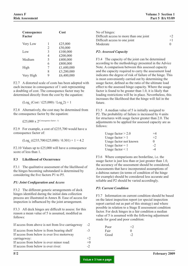
consequence cost factor
Very Low 1 £25,000 2 £50,000 Low 3 £100,000 4 £200,000 Medium 5 £400,000 6 £800,000 High 7 £1,600,000 8 £3,200,000 Very High 9 £6,400,000
F2.7 A distorted scale of costs has been adopted with each increase in consequence of 1 unit representing a doubling of cost. The consequence factor may be determined directly from the cost by the equation:
(Logn (Cost / £25,000) / Logn2) + 1
F2.8 Alternatively, the cost may be determined from the consequence factor by the equation:
£25,000 x 2(Consequence factor –1)
F2.9 For example, a cost of £235,700 would have a consequence factor of:
(Logn (£235,700/£25,000) / 0.301) + 1 = 4.2
F2.10 Values up to £25,000 will have a consequence score of less than 1.
f.3 likelihood of occurrence
F3.1 The qualitative assessment of the likelihood of the hinges becoming substandard is determined by considering the five factors P1 to P5.
P1: Joint Configuration and Access
F3.2 The different generic arrangements of deck hinges identified during the initial data collection process are illustrated in Annex B. Ease of access for inspection is influenced by the joint arrangement.
F3.3 All deck hinges are difficult to assess: for this reason a mean value of 5 is assumed, modified as follows:
If access from above is not from live carriageway -2
If access from below is from bearing shelf -3 If access from below is over live motorway carriageway: +2 If access from below is over minor road: +0 If access from below is over river: -2
f/2
No of hinges: Difficult access to more than one joint +2 Difficult access to one joint +1 Moderate 0
P2: Assessed Capacity
F3.4 The capacity of the joint can be determined according to the methodology presented in the Advice Note. A comparison between this assessed capacity and the capacity required to carry the assessment load indicates the degree of risk of failure of the hinge. This is most conveniently carried out by determining the usage factor, defined as the ratio of the ultimate load effect to the assessed hinge capacity. Where the usage factor is found to be greater than 1.0, it is likely that loading restrictions will be in place. Nevertheless, this increases the likelihood that the hinge will fail in the future.
F3.5 A median value of 5 is initially assigned to P2. The probability of failure is increased by 4 units for structures with usage factor greater than 2.0. The adjustments to be applied for assessed capacity are as follows:
Usage factor > 2.0 +4 Usage factor > 1 +2 Usage factor not known 0 Usage factor = 1 -2 Usage factor < 1 -4
F3.6 Where comparisons are borderline, i.e. the usage factor is just less than or just greater than 1.0, the accuracy of the assessment should be considered. Assessments that have incorporated assumptions of a dubious nature (in terms of condition of the hinge for example) should be considered less accurate and reliable and P2 should be varied accordingly.
P3: Current Condition
F3.7 Information on current condition should be based on the latest inspection report (or special inspection report carried out as part of this strategy) and where possible in relation to a Stage II assessment condition factor. For deck hinges in a fair condition a median value of 5 is assumed with the following adjustment made for good and poor condition:
Poor +2 Fair 0 Good -2
february 2009
volume 3 section 1 part 5 ba 93/09
annex f risk assessment
F3.8 If particular concerns or defects have been identified which may affect the performance of the joints a further +2 adjustment may be warranted. Such defects might include spalling of concrete around hinge, cracking through the hinge, evidence of leakage, sag or deformation of the deck. If repairs have been undertaken a negative adjustment may be appropriate to reflect the long-term improvement in condition. If repairs are only cosmetic then no adjustment is warranted.
Specific defects +2 Cosmetic or no repairs 0 Structural repair -2
P4: Rate of Deterioration
F3.9 A median value of 5 is assigned, modified as appropriate. Direct measurements of concrete properties such as concrete permeability, chloride contamination, cover, etc, are not currently widely available for the majority of deck hinges. However, there are other indicators which can give an insight as to whether the likely rate of deterioration will be greater or lesser than the average.
F3.10 The type and condition of the road surfacing and seal in the hinge will influence how much salt is likely to penetrate through the deck. Due to poor maintenance in the past, a median value for P4 of 5 is assumed. A deck hinge in poor condition is likely to result in cracking at the throat and chloride contamination of the hinge reinforcement. Depending on road joint condition the following adjustments are appropriate:
Poor +1 Fair 0 Good -1
F3.11 The level of salt use on a route is an important consideration as this is a major contributor for the deterioration of reinforced concrete structures. The following adjustments are adopted depending on the salt usage:
High +1 Medium 0 Low -1
P5: Future Loading
F3.12 Increased usage and congestion on a route will increase the probability of a deck hinge becoming substandard and so increase the rate of deterioration of road joints. Consideration should be given to current and future road widening schemes. Routes which are
february 2009
likely to experience unchanged and average traffic growth are assigned a median value of 5. Urban and strategic routes are likely to see greater increases in future loading and traffic volume than rural routes. Access roads are less likely to see any increase in loading. As a guide the following factors are appropriate: however, local knowledge should prevail.
Motorway +2 Dual A P Trunk Road +1 Single Carriageway Trunk Road 0 Lane/Local Road -2 Access Road/Footway -4
F.4 Significance Factors
F4.1 Not all contributing factors should be given equal weighting. The significance factor applies a weighting to the likelihood. For the risk assessment of deck hinges, the relative significance given to each factor can be taken as follows:
P1: Configuration and Access 2 P2: Current Capacity 4 P3: Current Condition 4 P4: Rate of Deterioration 2 P5: Future Loading 1
F4.2 Management effort will be greatest for those bridges deemed to be imminently substandard. The current capacity (P2) and current condition (P3) of a joint will be the primary factors affecting whether or not a deck hinge is likely to be substandard at the present time and are given a ‘high’ significance score of 4. For those bridges deemed to be of adequate capacity but actively deteriorating, management effort will be required to prevent further deterioration but this may be spread over a number of years. Factors (P1) joint configuration and access, and (P4) rate of deterioration, are factors which generally indicate the potential for a deck hinge to become substandard in the future and are assigned a significance factor of 2. Future loading (P5) is considered to be of low significance as future increases in loading can be planned for well in advance of any potential problems arising and is assigned a significance score of 1.
f.5 cost consequence
F5.1 The overall costs of repair comprise the design costs, the actual costs of undertaking repairs and the cost to the road user in terms of traffic delays. Traffic delay costs are often many times greater than the actual cost of repair and should be taken into consideration when considering the impact of a structure becoming
f/3
volume 3 section 1 part 5 ba 93/09
annex f risk assessment
substandard. For structures with a calculated likelihood factor of 6 or greater, the Agent is required to estimate the costs of undertaking repairs to the hinges. If the Agent has a clear understanding of the remedial measures to be adopted and a detailed estimate of repair is available (inclusive of user delay costs) these costs should be reported.
f.6 repair costs
F6.1 The repair techniques suitable for deck hinges are limited and cost estimates may assume the implementation of a particular repair technique to assess the relative consequences of a structure becoming substandard. It is important to note that this is a comparative exercise using limited data. The total works costs includes an allowance for access and traffic management costs. For bridges crossing a river or other watercourse access for repair by scaffolding off the deck may be assumed. For bridges over roads, access may be assumed to be via scaffolding from the road below.
F6.2 Generally traffic management will be required for repair from both above and below the deck. The nature of repairs is such that two running lanes are likely to be closed with contraflow running. The length of traffic management for contraflow may be assumed to be 5km for motorways and dual all purpose trunk roads, to accommodate cross-over points at an assumed distance of 3km. For single carriageway roads, traffic signalling with shuttle flow may be assumed. The time to undertake repairs is likely to be split say 75% from below deck and 25% from above deck and this would be reflected in the relative access and traffic delay costs incurred from above and below deck working.
F6.3 For underbridges over rail, access may be assumed to be by scaffold access tower and additional rail protection staff will also be required. Gaining access to a railway requires careful planning and liaison with the rail authorities to obtain track possessions. This will limit the time available to undertake repairs and every opportunity should made to limit the works duration undertaken from below deck. In this case the time to undertake repairs is more likely to be split 25% from below deck and 75% from above deck.
F6.4 For specialist repair techniques the ratio of design and contract preparation costs to works costs will be relatively high and may be assumed to be as high as 50% of the contract value for each bridge (which includes traffic management and access costs).
F
FuRRbcrd
Frthp
Fncn
•
•
•
•
•
•
Fthc
Fpdratraambaaa
F7a
f/4
.7 Traffic Delay Costs
7.1 Traffic user delay costs can be calculated sing the computer program QUeues And Delays at Oadworks (QUADRO). Tables contained in the Trunk oad Maintenance Manual (TRMM) – Volume 1 have een derived from QUADRO to estimate traffic delay osts for different scenarios of traffic management estriction. These tables have been used as the basis for eriving the traffic delay costs per day.
7.2 The traffic delay costs are related to the type of oad, the degree of the restriction, the daily traffic flow, e percentage of Heavy Goods Vehicles (HGV) and the
hysical length of the works on site.
7.3 The duration of the works above and below deck eeds to be considered to obtain the total traffic delay osts. To evaluate traffic delay costs it is generally ecessary to obtain the following information:
road classification;
the likely lane restriction;
annual average daily traffic (AADT) flows;
percentage of HGVs using the structure;
alternative routes for diversion if appropriate;
whether or not works are undertaken off-peak.
7.4 The type of repair or investigation will dictate e nature of the lane restrictions for each road
lassification.
7.5 In the absence of more local knowledge Table 4 resents typical traffic delay costs per 8 hour working ay for repair. The percentage of HGVs which use the oad influence the traffic user delay costs. Motorways re assumed to have 30% HGVs, dual all purpose unk roads 20% HGVs and single carriageway roads re assumed to have 10% HGVs. Motorway slip roads re classified as wide single carriageways: where two otorways join, the percentage HGVs is more likely to
e 30%. However, the difference in the costs for 10% nd 30% HGVs is minor and the assumption of 10% for ll situations is considered acceptable for the level of ccuracy required.
7.6 For minor roads with a width between 5.5m and .3m and two marked lanes the maximum traffic flow is ssumed to be 5,000 AADT. For access roads the costs
are assumed to be half those given for single carriage
february 2009
ways.

volume 3 section 1 part 5 ba 93/09
annex f risk assessment
F7.7 For repairs, two running lanes are assumed to be closed with contraflow running. The length of traffic management for contraflow is assumed to be 5km. For single carriageway roads, traffic signalling with shuttle flow is assumed. The traffic management proposed is such that traffic is unlikely to divert onto alternative roads and therefore, no additional factors have been applied to the TRMM tables.
F7.8 Off-peak or night working is considered practical for most short duration repair work. The traffic delay costs presented in the Table may be factored by 0.25 if off-peak working is a practical option to reflect the reduced volume of traffic.
f.
F8
•
•
•
F8cafro
unit rates for cost estimate
activity uaccess costsScaffolding for repair (for 35m deck width)Mobile elevated platformUnder bridge unitMobile Scaffold and Rail Protection StaffTraffic Management2 Lanes closed in contraflow1 Lane closedTraffic light controlJoint replacementAsphalticBuriedElastomericCombOther or unknownrepairDiscrete anode CP per m width of jointControl and monitoring equipment. (assumes one control cabinet per 4 joints)
february 2009
8 cost consequence factor
.1 The estimated costs should be identified as:
design costs;
works costs including access and traffic management;
traffic delay costs.
.2 The sum of the estimated costs should be used to lculate the consequence factor, determined directly m the cost by the equation:
(Logn (Cost / £25,000) / Logn2) + 1
nit rate unit works rate
£75 per day£300 per day£750 per day
£1,000 per day
£1,400 per day£300 per day£900 per day
£120 per m 14 m/day£75 per m 17 m/day£575 per m 7 m/day
£2,500 per m 3 m/day£200 per m 11 m/day
£360 per m 6 m/day
£6,000 Dual Carriageway£4,000 Single Carriageway
f/5
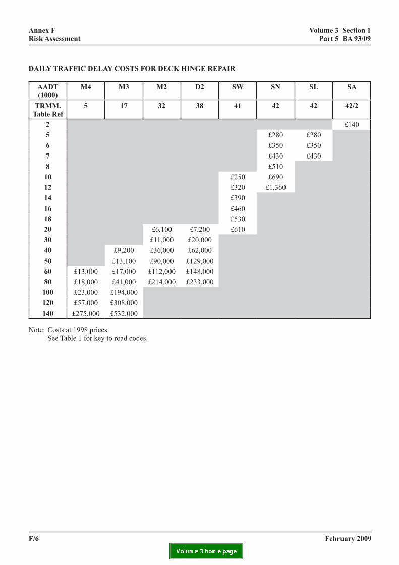
volume 3 section 1 part 5 ba 93/09
annex f risk assessment
daily traffic delay costs for deck hinge repair
aadt (1000)
m4 m3 m2 d2 sw sn sl sa
trmm.table ref
5 17 32 38 41 42 42 42/2
2 £1405 £280 £2806 £350 £3507 £430 £4308 £51010 £250 £69012 £320 £1,36014 £39016 £46018 £53020 £6,100 £7,200 £61030 £11,000 £20,00040 £9,200 £36,000 £62,00050 £13,100 £90,000 £129,00060 £13,000 £17,000 £112,000 £148,00080 £18,000 £41,000 £214,000 £233,000100 £23,000 £194,000120 £57,000 £308,000140 £275,000 £532,000
Note: Costs at 1998 prices. See Table 1 for key to road codes.
february 2009f/6
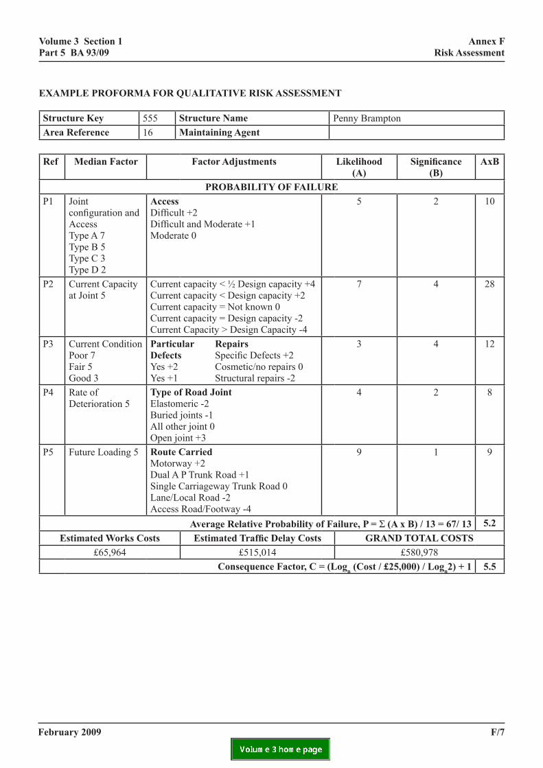
volume 3 section 1 part 5 ba 93/09
annex f risk assessment
example proforma for qualitative risk assessment
structure key 555 structure name Penny Bramptonarea reference 16 maintaining agent
ref median factor factor adjustments likelihood (a)
Significance (b)
axb
probability of failureP1 Joint
configuration and Access Type A 7 Type B 5 Type C 3 Type D 2
access Difficult +2 Difficult and Moderate +1 Moderate 0
5 2 10
P2 Current Capacity at Joint 5
Current capacity < ½ Design capacity +4 Current capacity < Design capacity +2 Current capacity = Not known 0 Current capacity = Design capacity -2 Current Capacity > Design Capacity -4
7 4 28
P3 Current Condition Poor 7 Fair 5 Good 3
particular repairs defects Specific Defects +2 Yes +2 Cosmetic/no repairs 0 Yes +1 Structural repairs -2
3 4 12
P4 Rate of Deterioration 5
type of road Joint Elastomeric -2 Buried joints -1 All other joint 0 Open joint +3
4 2 8
P5 Future Loading 5 route carried Motorway +2 Dual A P Trunk Road +1 Single Carriageway Trunk Road 0 Lane/Local Road -2 Access Road/Footway -4
9 1 9
average relative probability of failure, p = Σ (a x b) / 13 = 67/ 13 5.2estimated works costs Estimated Traffic Delay Costs grand total costs
£65,964 £515,014 £580,978consequence factor, c = (logn (cost / £25,000) / logn2) + 1 5.5
february 2009 f/7

volume 3 section 1 part 5 ba 93/09
annex f risk assessment
proforma for qualitative risk assessment
structure key structure namearea reference maintaining agent
ref median factor factor adjustments likelihood (a)
Significance (b)
axb
probability of failureP1 Joint
configuration and Access Type A 7 Type B 5 Type C 3 Type D 2
access Difficult +2 Difficult and Moderate +1 Moderate 0
P2 Current Capacity at Joint 5
Current capacity < ½ Design capacity +4 Current capacity < Design capacity +2 Current capacity = Not known 0 Current capacity = Design capacity -2 Current Capacity > Design Capacity -4
P3 Current Condition Poor 7 Fair 5 Good 3
particular repairs defects Specific Defects +2 Yes +2 Cosmetic/no repairs 0 Yes +1 Structural repairs -2
P4 Rate of Deterioration 5
type of road Joint Elastomeric -2 Buried joints -1 All other joint 0 Open joint +3
P5 Future Loading 5 route carried Motorway +2 Dual A P Trunk Road +1 Single Carriageway Trunk Road 0 Lane/Local Road -2 Access Road/Footway -4
average relative probability of failure, p = Σ (a x b) / 13 =estimated works costs Estimated Traffic Delay Costs grand total costs
£ £ £consequence factor, c = (logn (cost / £25,000) / logn2) + 1
february 2009f/8

volume 3 section 1 part 5 ba 93/09
ncy management
annex g highways agency management strategy
annex g highways age strategy
g1. management strategy : stage 1
Introduction
G1.1 Bridges owned by the Highways Agency incorporating hinge joints are located on the M1, M5, M6, A6, A45 and A52 trunk roads in the Midlands (see Annex D for list of structures known to contain deck hinges). Most have already been subject to visual inspection, and have been prioritised on the basis of their external condition, as outlined in Annex C. This document sets out a Management Strategy for all structures of this type, and is indicated in flow chart format in Annex A. This has been modified from that previously issued in Interim Advice Notes 40/01 and 51/03, and data capture and management has now been included in Annex E.
Data Validation
G1.2 A preliminary data collection exercise has already been undertaken and the structures identified as containing deck hinges are listed in Annex D. Any changes to the structures listed should be notified to TO and SSR AAG contacts to allow the structures in the hinge deck Structures Management Information System (SMIS) National Structures Programme Module (NSP) to be amended as necessary.
G1.3 Hinge deck structures which have not had a special inspection of the hinges (according to IAN 40/01 or IAN 51/03) as specified in SMIS Activities 1.1 and 1.2 should be inspected as soon as possible. Where inspections have previously been carried out, Agents should consider if the requirements are met, and, if not, should undertake the required inspection as soon as possible.
Initial Visual Inspection (SMIS Activity 1.1)
G1.4 Initial inspection based on based on a visual examination of the hinge joints should determine the severity and location of any defects such as cracking, leaching, or corrosion products leaking through the throat, and any concrete delamination and spalling in the vicinity of the hinge. Any deformation at the hinge or sag in the deck should be recorded and measured. The investigation should determine whether the hinge throat is cracked, and if so, crack widths should be estimated. Absence of visual evidence of defects should
february 2009
not be taken as assurance that no defects are present, as site investigations have shown the presence of corrosion damage without external indications. Access requirements for a more thorough or Detailed Inspection should be determined at this stage. The results of this inspection will be used to assign an initial priority to the structure within the NSP for hinge decks.
Detailed Inspection (SMIS Activity 1.2)
G1.5 The objective of a Detailed Inspection is to provide more detailed information on the condition of the hinge and to quantify any defects identified during the Initial Visual Inspection. The information provided should be in a form which can be used by the assessing engineer to determine the adequacy of the structure. Close access to the hinges will be required, so access platforms, traffic management, etc, will need to be arranged. Where cracking is present, widths should be determined. This can be done from below using a selection of feeler rods of different widths at a number of locations along the throat, and these locations marked for future reference. The number of measurements taken should be carefully interpreted and averaged to ensure that a reliable value for the crack width is reported. Bridge temperature should also be recorded since crack width may be influenced by seasonal temperature variation. Any deformation of the hinge or sag in the deck should be measured. The location of any damage or corrosion products in the vicinity of the hinge, or evidence of seepage through the deck, should be noted. Whilst carrying out a Detailed Inspection, the opportunity should be taken to install monitoring pips across existing cracks to enable periodic monitoring of future changes in crack width.
G1.6 In many cases, it will be effective to combine the Initial Visual Inspection and the Detailed Inspection depending on access requirements and what is currently known about the condition of the bridge from previous inspections.
Prioritisation
G1.7 Hinge deck structures should initially be prioritised on the basis of visual condition, according to the initial prioritisation methodology outlined in Annex C. Although it is acknowledged that there are some shortcomings in this approach, it does provide a useful
g/1
volume 3 section 1 part 5 ba 93/09
annex g highways agency management strategy
way of allocating resources early in the management programme. The prioritisation may be modified as further information is obtained. When allocating priorities, consideration should be given to current and future road improvement or widening schemes and the effects these might have on the service requirements of the bridge. When sufficient information is obtained a qualitative risk assessment should be carried out as described in Annex F.
Reporting
G1.8 Agents should report all inspection information as soon as possible to the HA regional office (TO and SSR AAG contacts), with recommendations for further investigation if necessary. This might include the use of non-destructive testing (NDT), or more extensive intrusive investigation of the hinge in order to determine the condition of the hinge reinforcement
Further Inspection (SMIS Activity 1.3)
G1.9 Where the hinges have significantly cracked (crack widths >2mm), or where there is evidence of significant seepage through the hinge, or where deformation of the joint is evident (shear deformation across the hinge, excessive rotation at the hinge), the opportunity should be taken to determine the condition of the throat reinforcement though more detailed site investigations. One method of doing this without significant intrusion and de-stressing of the reinforcement is to carefully drill small holes through the cracked hinge throat, and inspect bars using a borescope. If there is significant seepage, limited concrete condition testing should be carried out at the hinge to supplement data from earlier principal or special inspections. This should include measurement of chloride content, cement content, half-cell potential, and any other measurements deemed necessary by the engineer. Particular attention should be given to the condition of the vertical link reinforcement around the hinge, since this contributes significantly to the integrity of the joint. It may also be possible to identify the type of reinforcement used and whether it is misplaced.
G1.10 Where there are no indications of significant cracking, seepage, or other defects, no further immediate action is required provided the capacity of the hinge, assessed as described in G1.11 et seq, is adequate. Normal inspection and maintenance arrangements will apply. Agents should ensure that information relating to the condition of the hinge is included and recorded for use in the structural assessment. Where significant cracks have been observed, or where other defects or signs of
g/2
deterioration are present which give cause for concern the use of periodic monitoring should be considered: see G1.21.
Structural Assessment (SMIS Activity 1.4)
G1.11 A Preliminary Assessment should be carried out initially to determine the adequacy of the hinge. This should be based on a realistic analysis of the bridge deck. The hinges can be modelled as pins. Skews less than 10o will only have a small effect and can be ignored. Skews greater than 10o should be modelled correctly, with the line of the hinges positioned as it occurs in the deck. The analysis should be used to assess all load effects in the deck in accordance with BD 44. The shear capacity of the hinge is just one of the effects that should be considered: shear in the cantilever section can be the limiting factor in some deck configurations.
G1.12 Simplified conservative methods can be used to determine the shear capacity of the hinge and guidelines for an appropriate methodology are presented in main text of the Advice Note. Due account should be taken of the condition of the hinge determined through NDT and invasive inspection (see G1.16 et seq). If the adequacy of the joint cannot be demonstrated then a Detailed Assessment should be carried out. A methodology is presented in the main text of the Advice Note. Alternative methods can be used provided it is demonstrated that the hinge behaviour is adequately modelled.
G1.13 Use can be made of results from previous analyses results carried out using IAN 40/01 or IAN 51/03, updated as appropriate. Particular attention should be paid to the method of analysis adopted, and whether the assumptions made about the condition of the hinge are appropriate. The validity of any departures from standard previously granted should also be confirmed. It is recognised that previous assessments concentrated on the effects of the 40t assessment live load, and it may be necessary to reassess the structure in its present (ie, deteriorated and cracked) condition, taking account of construction defects such as poor concrete compaction, curing and reinforcement misalignment, where known.
G1.14 If the assessment reveals no strength deficiency and there are no concerns about the serviceability behaviour and durability of the structure, no further action need be taken and the bridge can be returned to the normal management cycle (SMIS Activity 2.1). However, because of the vulnerability of deck hinges to deterioration, Agents should review existing
february 2009
volume 3 section 1 part 5 ba 93/09
g/3
annex g highways agency management strategy
february 2009
structural assessment reports as part of the Steady State Assessment programme, and carry out new assessments as appropriate: see G3.1.
G1.15 Where assessment has shown that the capacity of the hinge is not adequate then action needs to be taken to ensure the safety of the structure and the road users. Depending on the condition of the structure, the rate of deterioration, and the conclusions of the strength assessment, consideration should be given to periodic monitoring, interim measures and the development of a remedial works leading to a long-term solution, as outlined in the following sections. An important aspect of identifying the most appropriate action is the management of risk: see G1.25.
Invasive Inspection and Non-destructive Testing (SMIS Activity 1.5)
G1.16 Detailed assessment requires accurate information on the condition of the hinge and its geometry, and this can only be obtained by invasive inspection, testing and non-destructive methods. Full advantage should be taken of NDT techniques, but if it is considered that there is still insufficient information about the condition of the hinge and its reinforcement for assessment purposes, further invasive testing to expose the reinforcement in the hinge may be necessary. Such investigations will be subject to technical approval procedures and should be supported by a full technical appraisal – see G1.18. This should safeguard the structure during the course of the work, set down the type of investigation proposed and details of the expected outputs, and outline how the results of the investigations will be used.
G1.17 Consideration should be given to selecting the most appropriate test methods and the most suitable test location(s) on the bridge using the risk assessment approach outlined in G1.25. Consideration should also be given to, drainage paths and the severity of defects, together with safety, access and traffic management issues. Where invasive testing involves de-stressing the hinge joint, the additional loading carried by adjacent sets of hinge bars should be assessed. Analysis should be used to determine to whether it is necessary to prop the bridge when individual hinges are broken out. If propping is to be utilised, the analysis should be extended to determine the magnitude and position of the propping load, its effect on the hinge, and its effect on elements remote from the hinge.
G1.18 Agents should submit detailed proposals for invasive testing to TO and SSR AAG for discussion and agreement, including the method, timescale, cost,
materials tests and inspection, reinstatement procedures, traffic management, noise control and contingency measures, etc. Particular attention should be given to planning the reinstatement of the test areas, the selection of materials, and method of reinstatement, taking account of time constraints, potential weather conditions and engineering requirements. Contingency measures should be planned to take into account difficulties encountered during the invasive testing process, including the condition of the exposed hinge reinforcement, unexpected delays and weather conditions.
G1.19 NDT methods such as impact echo, radiography, acoustic emission, and thermography, etc, may be used to minimise the need for invasive inspection. Radiography and acoustic emission have been used on hinge decks, and appear to be useful techniques. In the case of acoustic emission some fieldwork and research has been undertaken to assess whether the technique will detect cracking in concrete or reinforcement corrosion. Not all of this work has been related to hinge structures. Further research has been carried out to characterise the outputs, in order to build confidence that the technique can be used to quickly gauge conditions on site. Whilst NDT methods at present are unlikely to give definitive indications of defects, they may be used to assist determination of the variations in condition along joints, and also allow coverage of large areas in a relatively short time. The results, properly interpreted and compared to known conditions at one or more locations derived by invasive inspection, should give a good indication of conditions, or point to where further invasive inspection may be necessary. In addition to the above test methods, reinforced concrete tomography using a gamma ray source does offer some promise as a means to detect defects and corrosion in hinges, though it is yet to be fully calibrated against known defects in deck hinges or trialled in the UK.
G1.20 Recent experience of invasive inspection and testing of hinge deck structures has been gained in South Wales. This was undertaken using water-jetting to create small ‘pockets’ for inspection. These investigations revealed that:
i) As-built drawings are sometimes inaccurate, and there can be construction defects that significantly affect an assessment, such as: displaced joint formwork; concrete bridging across the gap; misaligned throat reinforcement that does not cross the throat at the same location.
volume 3 section 1 part 5 ba 93/09
annex g highways agency management strategy
ii) Leakage is not necessarily a true indicator of corrosion potential. Severe pitting corrosion can exist within outwardly ‘dry’ joints, where the carriageway joint filler soaks up chlorides in small but concentrated quantities. On the other hand severe leakage may dilute chlorides and wash out the joints. Even with full exposure, pitting corrosion is not easy to see and measure, and it is possible that the use of a borescope alone may miss important defects.
Monitoring (SMIS Activity 1.6)
G1.21 Where significant defects are present and there are some concerns about the serviceability and strength of the hinge, a regime of periodic monitoring and inspection may provide a short-term solution pending implementation of a permanent solution such as repair or strengthening of the hinge, or replacement of the bridge. Some general guidelines on monitoring are presented in BA 79 ‘Management of sub-standard highway structures’. Monitoring can be considered in cases where bridge works are likely to cause excessive disruption to traffic or where costs would be disproportionate to the benefits achieved. The objective of the monitoring is to enable the structure to remain in service, while examining its behaviour to identify any changes indicating a reduced reliability. This might include monitoring some or all of the following:
i) progressive horizontal and vertical movement at the joint;
ii) changes in crack width and length;
iii) movement under traffic loading;
iv) increasing strains at critical locations;
v) ongoing material deterioration.
G1.22 The sophistication of the monitoring scheme will depend on the particular circumstances (condition, assessed capacity, access, conclusions of risk analysis, etc). At the lowest level, monitoring can be based on a visual approach to avoid the need for sophisticated instrumentation or logging systems. In some cases it may be appropriate to utilise continuous monitoring using strain or other movement gauges. The intervals for monitoring should be appropriate for the structure (eg. 3 months to 1 year), depending on the nature and severity of the deterioration, and the potential risk to the network.
GunmeicaminacdeofApr
Gstefa inw
R
GfatodefaVbrprouasAabanarmfaRmwfalik
In
GanIntoinwofprst
g/4
1.23 Monitoring of movement at the hinge can be dertaken using a demountable strain gauge to take anual measurement between DEMEC pips bonded ther side of the hinge. Displacement transducers n be mounted across the hinge if continuous easurements are required. The location of the strumentation on the bridge depends on ease of cess but would normally be on the underside of the ck. Manual monitoring is perhaps best used as part an initial investigation into structural performance. utomatic or remote monitoring can be used to enable ior warning of structural problems.
1.24 The use of monitoring to ensure the safety of a ructure requires careful management if it is to be used fectively and reliably. The on-going management of monitoring scheme (SMIS Activity 2.3) is considered G3.5. Agents should discuss and agree the proposals ith HA regional office (TO and SSR AAG contacts).
isk Management
1.25 Risks should be assessed considering usage ctors (defined as the ratio of the ultimate load effect the assessed hinge capacity: see Annex G), rates of terioration, potential modes of failure, and network ctors such as traffic volume and Heavy Goods ehicle (HGV) loading over and under the bridge, idge location and alternative routes, etc. An initial ioritisation can be carried out using the methodology tlined in Annex C. Where a more detailed qualitative sessment is required nnex F can be used once more detailed information out condition and capacity are available. Example d blank proformas for the qualitative risk assessment e given, together with detailed guidance on the ethodology. Structures with hinges with a likelihood ctor of 6 or higher determined according to the isk Assessment in Annex F, are likely to require anagement effort in the near future to ensure they ill not become substandard. The higher the likelihood ctor the more urgent the need for remedial action is ely to be.
terim Measures (SMIS Activities 1.7 and 1.8)
1.26 If the results of these investigations reveal unacceptable risk to the integrity of the structure, terim Measures should be developed and implemented safeguard the road network. Such measures might clude temporary propping, load reduction (lane or eight restrictions), temporary repair or strengthening the hinge, or some combination of these. The ocedures outlined in BA 79 ‘Management of sub-andard highway structures’ should be instigated, and
february 2009
volume 3 section 1 part 5 ba 93/09
annex g highways agency management strategy
Technical Approval procedures for the temporary works will apply. Interim Measures are by definition temporary for a specified period of time, pending the formulation and execution of a permanent solution (permanent repair, strengthening or replacement). Careful management is required to ensure that Interim Measures are installed correctly (SMIS Activity 1.8) and remain effective for as long as they remain in service (SMIS Activity 1.8): see section G3.3.
Data Management
G1.27 As part of this Maintenance Strategy, the SMIS system will be used to manage the programme of work on hinge deck structures. To assist HA in developing an effective Management Strategy, it is important that Agents input the required data (refer to Annex E) when required. This will assist Agents in managing their own programmes as well as allowing the Agency to produce and assess national progress reports. It will be necessary for Agents to populate SMIS with the necessary ‘historic’ data for work already completed.
Research
G1.28 Research was commissioned at TRL to investigate the durability of deck hinges in a deteriorated condition. The research was based on a programme of laboratory testing, supported by a theoretical study to model the behaviour of hinge deck structures. This, along with previous research, provided the basis for this Management Strategy. Further research is being carried out to assist the development of robust and reliable NDT methods which can be used to determine the condition of the steel reinforcement at and adjacent to the hinge throat. Advantage should be taken of these developments where appropriate.
g2. maintenance and remedial works
Maintenance
G2.1 For all hinge deck bridges, high priority should be given to preventing further deterioration of hinge joints by maintaining drainage in working order and the integrity of deck waterproofing and expansion joints, including pipe bays where appropriate. Bids for remedial works should be classified as essential maintenance. Advantage should also be taken during any planned re-waterproofing or resurfacing work to undertake a detailed visual inspection of the concrete and reinforcement at the hinges.
R
GptewocreathWwC
Gdao
Gdrecpdfoitec
GtefetoteseBca
Grerecsymsu
Gthethn
february 2009
emedial Works
2.2 Irrespective of the interim measures adopted, roposals should be devised to provide for the long-rm safety/stability of the structure. Remedial options ill vary between minor concrete repairs, reconstruction f the hinges, safeguarding measures such as props, onsideration of re-articulation of the deck and complete construction. All maintenance operations measures
re likely to affect the integrity of the structure and will erefore be subject to technical approval procedures. here they are significant then independent checks ill also be required, and they will be considered as ategory 3.
2.3 The repair of hinges is made particularly ifficult due to poor access, congested reinforcement nd traffic management issues. Advice is given below n possible repair methods
2.4 Concrete replacement is an option for repairing eteriorated concrete. Information on concrete placement is provided in BD 27 ‘The repair of
oncrete highway structures’. The HA/CSS/TRL ublication, ‘Best practice guidance for concrete repair’ etails current thinking on best practice to be adopted r concrete repair. Unless such practices are adopted,
is likely that concrete repairs will only be partially ffective in minimising future corrosion of reinforced oncrete.
2.5 Other options such as the use of electrochemical chniques, including cathodic protection may be asible in the future, in some circumstances, as a means minimise future corrosion. However, electrochemical chniques are currently not advised where there are nsitive structural details such as hinges (refer A 83 ‘Cathodic protection for use in reinforced oncrete structures’), and would need very careful ssessment and specialist advice before adoption.
2.6 There are a number of alternative commercial pair systems available to manage deteriorating inforced concrete such as, chloride extraction,
athodic protection, and active moisture reduction stems. The effectiveness of these particular remedial ethods for use on hinge joints is not yet proven and as ch they are not considered appropriate at this time.
2.7 Where a hinge joint has deteriorated so badly at it is practically or economically beyond repair, for
xample where the reinforcement is so badly corroded at it cannot be satisfactorily reinstated, then it may be
ecessary to replace the whole element.
g/5
volume 3 section 1 part 5 ba 93/09
annex g highways agency management strategy
g3. management strategy: stage 2
Future Management (SMIS Activity 2.1)
G3.1 Notwithstanding the conclusions of the appraisal outlined in the preceding sections of this document, the vulnerability of concrete hinges to deterioration requires that bridges containing these details need careful management in the long-term. SMIS activities 2.1, 2.2 and 2.3 define how the structure is to be managed in the future depending on the outcome of this assessment.
G3.2 Where assessment has shown that the hinges are performing satisfactorily and their strength is adequate, no special action is required other than the normal inspection/maintenance activities. Experimental tests and theoretical analysis of hinge joints in as-built condition and with simulated defects have shown that there is a generous factor of safety in capacity over applied loading. However, it is likely that capacity may be reduced in structures exhibiting significant deterioration. Where hinge deck structures are exhibiting significant deterioration, Agents should review existing structural assessment reports as part of the Steady State Assessment programme, and carry out new assessments as appropriate. This may be triggered by changes in condition as reported through the routine General/Principle Inspection regime.
Management of Interim Measures (SMIS Activity 2.2)
G3.3 Where Interim Measures have been adopted, Agents should ensure that they remain effective throughout their service life. In devising and planning the Interim Measures, consideration should be given to how they are to be managed, and procedures for their inspection and maintenance need to be developed and incorporated into the routine General/Principle Inspection regime (SMIS Activity 2.2).
G3.4 Interim Measures are not a permanent solution and should only be continued while an appropriate long-term solution is determined and implemented. The service life of these measures should be specified at the time of implementation, and should take due account of the condition of the hinge, the rate of deterioration, the assessment results, and the risk analysis. All Interim Measures should be subjected to a 2-yearly review, coinciding with the General Inspection cycle, at which time the decision should be taken whether to continue with them, or whether a permanent solution is required. The review should take account of the current condition, in-service behaviour, traffic levels, and the costs and benefits of implementing a permanent solution.
M
GcstpsaboaiatcoBs
g/6
anagement of Monitoring (SMIS Activity 2.3)
3.5 The purpose of monitoring is to identify hanges in behaviour which might compromise the afety of the structure. Effective management requires hat the monitoring be focussed on critical measurable arameters (eg, condition, crack widths deflections, sag, train) and that acceptable thresholds are defined. If ny of these thresholds are exceeded, the hinge should e examined urgently to determine the next course f action. The monitoring should be continued until n appropriate long-term solution is determined and mplemented. The monitoring period should be specified t the time of implementation and should be subject o regular review, taking due account of the changing ondition and behaviour of the structure. General advice n the formulation of Monitoring systems is given A 79, ‘Management of sub-standard highway
tructures’.
february 2009