Dmitri V. Petrov- Vortex-edge dislocation interaction in a linear medium
6
Vortex±edge dislocation interaction in a linear medium Dmitri V. Petrov * Department of Fundamental Chemistry, University Federal of Pernambuco, Recife, CEP 50670-901, Brazil Received 30 August 2000; received in revised form 6 November 2000; accepted 11 December 2000 Abstract The interaction of a vortex and an edge phase dislocation nested in a Gaussian beam by its free-space propagation is studied experimentally and theoretically in the paraxial regime. This interaction induces the nucleation of additional vortices of both topological charges. Their positions and number depend on the initial shift of the edge dislocation relative to the vortex. Ó 2001 Published by Elsevier Science B.V. PACS: 42.25.Bs; 42.25.Hz Keywords: Optical phase singularities; Optical vortex; Optical edge dislocation; Gauss±Hermite modes; Angular momentum of light Optical ®elds may contain topological defects of pha se, tha t is, points or lines on the wavef ront surface whe re bot h the real part and imaginary part of the ®eld are equal to zero [1]. There are two typ es of pha se def ects or disloc ati ons . A scr ew dislocation or vortex is a spiral phase ramp around the point of phase singularity where the phase of the wave is unde ®ned thus it s ampl itude must vanish. The order of the singularity multiplied by its sign is referred to as the topological charge of vortex. The doughnut mode of a laser cavity is an example of an optical vortex. An edge dislocation is the p-shift in the wave phase located along a line in the transverse plane. The Gauss±Hermite mode H 1;0 is the simplest example of a ®eld with edge dislocation. The propagation dynamics of a vortex in both lin ear and nonl inear medi a is aected by any source of the phase gradient and (or) the intensity gradient, and it has been the subject of numerous publications (see, e.g., Refs. [2±16]). In particular, in a linear medium two vortices interact and their positions relative to each other and relative to the host beam change as they propagate [2,3,10±12]. Publica tions on the propa gati on dyna mics of edge dislocations are few. The nonlinear evolution of an edg e dislocation was studied in an aniso- tro pic pho tor efr act ive mat eri al [17 ,18 ], and in a defocusing Kerr medium [19 ]: at hig h int ensities this dislocation is unstable and break up into pairs of vortices. The aim of this paper is to study experimentally the interactio n bet wee n a sin gle -charged vor tex and an edge dislocation nested in a smooth Gauss- ian beam by its propagation in a linear medium. This work was st imu lat ed by a re cent paper of Kivshar et al. [20] on vortex±stripe soliton inter- actions in a nonlinear defocusing medium. It was observed a vortex-i nduced dark st ri pe solit on (cont aining an edge dislocat ion) bending and its 15 February 2001 Optics Communications 188 (2001) 307±312 www.elsevier.com/locate/optcom * Tel.: +55-81-3271-84 40; fax: +55-81-32 71-8442. E-mail address: [email protected] (D.V. Petrov). 0030-4018/01/$ - see front matter Ó 2001 Published by Elsevier Science B.V. PII: S0030-4018(01)00993-2
Transcript of Dmitri V. Petrov- Vortex-edge dislocation interaction in a linear medium

8/3/2019 Dmitri V. Petrov- Vortex-edge dislocation interaction in a linear medium
http://slidepdf.com/reader/full/dmitri-v-petrov-vortex-edge-dislocation-interaction-in-a-linear-medium 1/6
Vortex±edge dislocation interaction in a linear medium
Dmitri V. Petrov *
Department of Fundamental Chemistry, University Federal of Pernambuco, Recife, CEP 50670-901, Brazil
Received 30 August 2000; received in revised form 6 November 2000; accepted 11 December 2000
Abstract
The interaction of a vortex and an edge phase dislocation nested in a Gaussian beam by its free-space propagation is
studied experimentally and theoretically in the paraxial regime. This interaction induces the nucleation of additional
vortices of both topological charges. Their positions and number depend on the initial shift of the edge dislocation
relative to the vortex. Ó 2001 Published by Elsevier Science B.V.
PACS: 42.25.Bs; 42.25.Hz
Keywords: Optical phase singularities; Optical vortex; Optical edge dislocation; Gauss±Hermite modes; Angular momentum of light
Optical ®elds may contain topological defects of phase, that is, points or lines on the wavefront
surface where both the real part and imaginary
part of the ®eld are equal to zero [1]. There are two
types of phase defects or dislocations. A screw
dislocation or vortex is a spiral phase ramp around
the point of phase singularity where the phase of
the wave is unde®ned thus its amplitude must
vanish. The order of the singularity multiplied by
its sign is referred to as the topological charge of
vortex. The doughnut mode of a laser cavity is an
example of an optical vortex. An edge dislocation
is the p-shift in the wave phase located along a line
in the transverse plane. The Gauss±Hermite mode
H 1;0 is the simplest example of a ®eld with edge
dislocation.
The propagation dynamics of a vortex in both
linear and nonlinear media is aected by any
source of the phase gradient and (or) the intensitygradient, and it has been the subject of numerous
publications (see, e.g., Refs. [2±16]). In particular,
in a linear medium two vortices interact and their
positions relative to each other and relative to the
host beam change as they propagate [2,3,10±12].
Publications on the propagation dynamics of
edge dislocations are few. The nonlinear evolution
of an edge dislocation was studied in an aniso-
tropic photorefractive material [17,18], and in a
defocusing Kerr medium [19]: at high intensities
this dislocation is unstable and break up into pairs
of vortices.
The aim of this paper is to study experimentally
the interaction between a single-charged vortex
and an edge dislocation nested in a smooth Gauss-
ian beam by its propagation in a linear medium.
This work was stimulated by a recent paper of
Kivshar et al. [20] on vortex±stripe soliton inter-
actions in a nonlinear defocusing medium. It was
observed a vortex-induced dark stripe soliton
(containing an edge dislocation) bending and its
15 February 2001
Optics Communications 188 (2001) 307±312
www.elsevier.com/locate/optcom
*Tel.: +55-81-3271-8440; fax: +55-81-3271-8442.
E-mail address: [email protected] (D.V. Petrov).
0030-4018/01/$ - see front matter Ó 2001 Published by Elsevier Science B.V.P II: S0 0 3 0 -4 0 1 8 (0 1 )0 0 9 9 3 -2

8/3/2019 Dmitri V. Petrov- Vortex-edge dislocation interaction in a linear medium
http://slidepdf.com/reader/full/dmitri-v-petrov-vortex-edge-dislocation-interaction-in-a-linear-medium 2/6
break up into vortices. This rises the question how
this interaction manifests itself in a linear medium
because the above mentioned mechanisms of in-
teraction between dislocations present in this case
too.
The experiments were designed with the fol-
lowing guidelines. First, only a vortex will be
nested into a Gaussian beam and the phase dis-
tribution in the beam after free propagation will be
monitored using interferometric technique. Sec-
ond, only an edge dislocation will be nested in the
Gaussian beam and its phase structure will be also
analyzed. Then, the both dislocations will be em-
bedded in the beam and the beam's intensity and
phase distributions will be studied at dierent ini-
tial positions of the edge dislocation relative to thevortex being always at the center of the Gaussian
beam.
A single-charge vortex in a Gaussian beam
from a He±Ne laser k 0:6328 lm was gener-
ated using an on-axis computer-generated spiral
zone plate (60 cm focal length) [21]. A diameter of
the mask was 0.6 cm. To separate the beam with
vortex from the undiracted light and high-order
Fresnel images, a lens with 10 cm focal length was
placed at the fundamental focus of the zone plate.
An image of the beam or an interference patternobtained with a reference beam was observed on a
screen located at about one Rayleigh length from
the lens and was recorded with a charge-coupled
device camera. Fig. 1a and b shows the intensity
distribution of the beam with the vortex and cor-
responding interference pattern. The extra fringe
generated at the phase dislocation is clearly visible.
An edge phase dislocation was created by a p-
phase jump imposed across the beam by a thin
glass plate [17,18]. Interference of the reference
beam with the light passed through the plate was
used to adjust the tilt of the glass plate to ensure a
phase shift of about 2pn p between the two
halves of the beam (Fig. 1c and d). One can readily
observe this one-half fringe shift of the interference
fringes.
To generate the both phase dislocations in the
Gaussian beam the thin glass plate was introduce
in the beam just before the computer-generated
spiral zone plate as shown in Fig. 2. No dierencein experimental results was observed whether the
glass plate was placed before or after the spiral
zone plate.
When the both phase dislocations are on-axis of
the host Gaussian beam, the intensity distribution
and corresponding interference pattern (Fig. 3a
and b) change considerably. Two vortices of the
same topological charge (which is equal to the sign
of the input vortex) present now as a result of the
interaction of the dierent types of phase disloca-
tions. The edge dislocation alone does not ob-served.
If the vortex is on-axis but the edge dislocation
is oset to the right (the shift from the center of the
vortex is about 0.1 cm), a new vortex (3) opposite
in sign to other vortices (1) and (2) is observed as
well as an asymmetry of the intensity distribution
(Fig. 3c and d). By further shift of the edge dis-
Fig. 1. Experimental images of intensity and interferogram for
the output beam (a, b) with vortex or (c, d) with edge disloca-
tion.
Fig. 2. Diagram of the experimental setup. GP, glass plate;
MASK, computer-generated hologram; L, lens.
308 D.V. Petrov / Optics Communications 188 (2001) 307±312
8/3/2019 Dmitri V. Petrov- Vortex-edge dislocation interaction in a linear medium
http://slidepdf.com/reader/full/dmitri-v-petrov-vortex-edge-dislocation-interaction-in-a-linear-medium 3/6
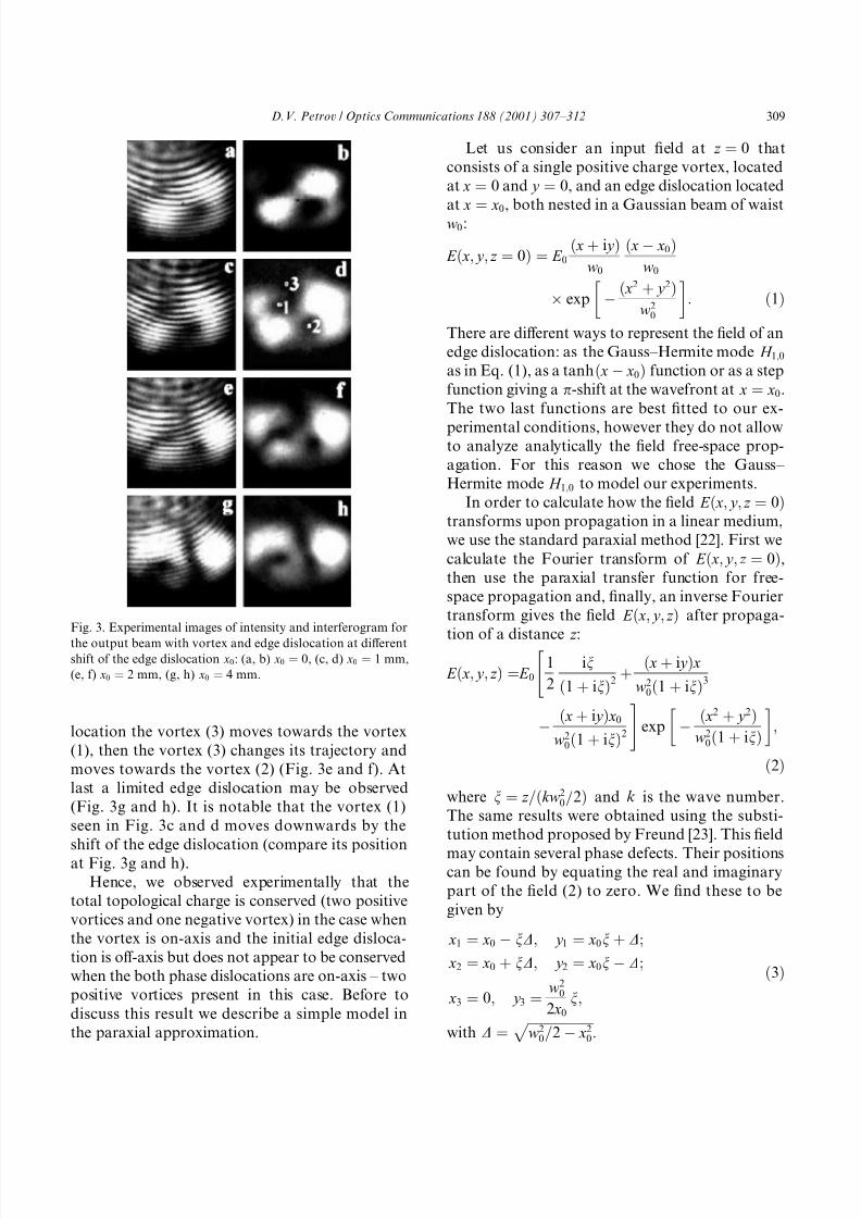
location the vortex (3) moves towards the vortex
(1), then the vortex (3) changes its trajectory and
moves towards the vortex (2) (Fig. 3e and f). At
last a limited edge dislocation may be observed
(Fig. 3g and h). It is notable that the vortex (1)
seen in Fig. 3c and d moves downwards by the
shift of the edge dislocation (compare its position
at Fig. 3g and h).
Hence, we observed experimentally that the
total topological charge is conserved (two positive
vortices and one negative vortex) in the case when
the vortex is on-axis and the initial edge disloca-
tion is o-axis but does not appear to be conserved
when the both phase dislocations are on-axis ± two
positive vortices present in this case. Before to
discuss this result we describe a simple model in
the paraxial approximation.
Let us consider an input ®eld at z 0 that
consists of a single positive charge vortex, located
at x 0 and y 0, and an edge dislocation located
at x x
0, both nested in a Gaussian beam of waist
w0:
E x; y ; z 0 E 0 x i y
w0
xÀ x0w0
 exp
À x2 y 2
w20
: 1
There are dierent ways to represent the ®eld of an
edge dislocation: as the Gauss±Hermite mode H 1;0as in Eq. (1), as a tanh xÀ x0 function or as a step
function giving a p-shift at the wavefront at x x0.
The two last functions are best ®tted to our ex-
perimental conditions, however they do not allowto analyze analytically the ®eld free-space prop-
agation. For this reason we chose the Gauss±
Hermite mode H 1;0 to model our experiments.
In order to calculate how the ®eld E x; y ; z 0transforms upon propagation in a linear medium,
we use the standard paraxial method [22]. First we
calculate the Fourier transform of E x; y ; z 0,then use the paraxial transfer function for free-
space propagation and, ®nally, an inverse Fourier
transform gives the ®eld E x; y ; z after propaga-
tion of a distance z :
E x; y ; z E 0 1
2
in
1 in2
" x i y xw2
01 in3
À x i y x0
w201 in2
#exp
À x2 y 2w2
01 in;
2where n z =kw2
0=2 and k is the wave number.
The same results were obtained using the substi-
tution method proposed by Freund [23]. This ®eld
may contain several phase defects. Their positionscan be found by equating the real and imaginary
part of the ®eld (2) to zero. We ®nd these to be
given by
x1 x0 À nD; y 1 x0n D;
x2 x0 nD; y 2 x0nÀ D;
x3 0; y 3 w20
2 x0
n;
3
with D w2
0=2 À x20
p :
Fig. 3. Experimental images of intensity and interferogram for
the output beam with vortex and edge dislocation at dierentshift of the edge dislocation x0: (a, b) x0 0, (c, d) x0 1 mm,
(e, f) x0 2 mm, (g, h) x0 4 mm.
D.V. Petrov / Optics Communications 188 (2001) 307±312 309

8/3/2019 Dmitri V. Petrov- Vortex-edge dislocation interaction in a linear medium
http://slidepdf.com/reader/full/dmitri-v-petrov-vortex-edge-dislocation-interaction-in-a-linear-medium 4/6
Below we analyze trajectories of these vortices
by changing x0 assuming that the propagation
distance is constant. Our experiment was per-
formed under this condition.
If x0 0 the output ®eld contains two vortices
x1; y 1 and x2; y 2 and this was observed in ex-
periments (Fig. 3a and b). The third vortex x3; y 3is at in®nity y 3 3I. I f 0 < x0 < w0=
2
p xÃ0,
the output ®eld contains three vortices. Using the
de®nition of vortex topological sign introduced by
Freund [4,5], two vortices x1; y 1 and x2; y 2 are
positive (i.e. they have the same sign as the input
vortex), and the sign of the vortex x3; y 3 is neg-
ative. If x0 xÃÃ0 nw0=21 n21=2
the vortex
x1; y 1
annihilates with the vortex
x3; y 3
, however
by further increase of x0 the ®eld contains againthree vortices. Two of them are positive and the
third is negative. At x0 xÃ0 the vortex x3; y 3 an-
nihilates with the vortex x2; y 2, and only one
positive vortex x1; y 1 survives.
Fig. 4a shows the trajectories of the three vor-
tices calculated by w0 1 and at n 1. Fig. 4b±g
illustrates the intensity distributions and interfer-
ence patterns, calculated from Eq. (3) at dierent
positions of the edge dislocation x0.
At given shift x0 the initially straight edge dis-
location bents when propagation distance in-creases. In two nulls located at the bent curve a
pair of screw dislocation appears.
Numerical simulations of the full governing
equation describing the beam propagation in a
linear medium in the paraxial approximation was
performed with a split-Fourier algorithm [24]. We
used three function to model the edge dislocation:
the Gauss±Hermite H 1;0 function xÀ x0=w0 as in
Eq. (1), the tanh-like beam tanh xÀ x0=b, where
b describes the amplitude pro®le near x x0, and
the step function P xÀ x0
, where P
xÀ x0
1 if
x > x0, and P xÀ x0 À1 if x < x0, that gives a
p-phase shift of the ®eld at x x0.
Some examples of numerical simulations (Fig.
5) show very good agreement with the predictions
of Eq. (3) within the resolution that was achievable
with split-step meshes. The number of vortices and
their positions are almost independent on the type
of functions used to describe the edge dislocation.
It means that the intensity gradient (that is dier-
ent in both cases) does not contribute considerably
in the interaction between the dislocations. Com-
paring these plots with the experimental data on
Fig. 3, an agreement between theory and experi-
ment may give us some con®dence to the model
proposed.
Fig. 4. (a) Calculated trajectories of the vortices with positive(solid lines) and negative sign (dash line). Intensity and inter-
ferogram for dierent shift of the edge dislocation x0: (b, c)
x0 0, (d, e) x0 0:3, (f, g) x0 0:7. Conditions: n 1, w0 1.
310 D.V. Petrov / Optics Communications 188 (2001) 307±312

8/3/2019 Dmitri V. Petrov- Vortex-edge dislocation interaction in a linear medium
http://slidepdf.com/reader/full/dmitri-v-petrov-vortex-edge-dislocation-interaction-in-a-linear-medium 5/6
One can explain a break up of the edge dislo-
cation and the generation of additional screwdislocations in the following simple way. The ex-
pression (1) can also be written as
E x; y ; z 0 E 0 x2 i yxÀ xx0 À i yx0
 exp
À x2 y 2
w20
; 4
which is a superposition of Gauss±Hermite modes
H mn x; y : E x; y ; z 0 H 20 i H 11 H 10 i H 01
H 00. As well known the amplitude distribution
of these modes have numerous intersections with
zero. Therefore the conditions of vanishing both
the real and imaginary parts can be satis®ed at
several points. These modes will acquire dierent
phase shifts (proportional to the indices of modes)
upon propagation. The positions of the defects are
thus not expected to remain stationary.
Therefore, the calculations based on the simple
model also showed that the total topological
charge does not conserved in free-space propaga-
tion when the both phase dislocations are on-axis.
For the ®rst time the violation of topological
charge conservation was mentioned by Soskin
et al. [14]. It was shown that during free-space
propagation of a light wave, which is a combina-tion of a Gaussian beam and an optical vortex
within a Gaussian envelope, additional vortices
appear or annihilate. In spite of any variation in
the number of vortices, the total angular momen-
tum is constant during the propagation. Even
when all vortices may be suppressed, the wave-
front of the beam still has folds, but in a smooth
surface without defects. These folds and not just
screw phase dislocations produce components of
angular momentum. Moreover, it was shown that
by some choices of parameters the combination of a Gaussian beam and a single-charge optical vor-
tex gives a wave with two single-charge vortices of
the same sign. In our case of interaction between
two topological phase defects we observed the
similar eect. By parametric wave mixing the vio-
lation of topological charge conservation was ob-
served in Refs. [25,26].
Now let us compare our results obtained in the
linear case with the nonlinear case studied in Ref.
[20]. In the nonlinear case by propagation of each
of the phase dislocation the diraction eect is
suppressed due to the nonlinear change of refrac-
tive index: they propagates as a vortex dark soliton
or as a stripe dark soliton. In the linear case the
diraction is strong enough (compare the initial
and ®nal beam sizes in Fig. 5). Nevertheless all
basic eects observed in the nonlinear case due to
the interaction between the two dislocations (the
stripe bending, the generation of a pair of new
vortices and the shift of initial vortex) present also
in the linear case. As it was mentioned in Ref. [20]
Fig. 5. (a, c, e, g) Numerically obtained beam intensity distri-
butions and (b, d, f, h) corresponding interferograms at a ®xed
propagation distance n 0 (a, b, e, f) and n 1 (c, d, g, h).
Plots were calculated with the edge dislocation modeled as
xÀ x0=w0 (a±d) or tanh xÀ x0=b with b 0:01 (e±h). Re-
sults found with step function P xÀ x0 are not shown because
they are very similar to ones obtained with tanh xÀ x0=b:Parameters: w0 1, x0 0:3:
D.V. Petrov / Optics Communications 188 (2001) 307±312 311

8/3/2019 Dmitri V. Petrov- Vortex-edge dislocation interaction in a linear medium
http://slidepdf.com/reader/full/dmitri-v-petrov-vortex-edge-dislocation-interaction-in-a-linear-medium 6/6
``the main eect produced by a vortex on the dark-
soliton stripe is associated with the vortex phase
gradient'' and apparently this is right for the linear
propagation.
In conclusion, the interaction of the vortex and
the edge phase dislocation nested in a Gaussian
beam induces nucleation of additional vortices of
both topological charges. Their positions depend
on the initial shift of the edge dislocation relative
to the vortex. The total topological charge is
conserved in the case when the edge dislocation is
o-axis and the initial vortex is on-axis, but does
not appear to be conserved in the on-axis case for
the both dislocations.
Acknowledgements
I greatly appreciate I. Freund for enlightening
discussions.
References
[1] J.F. Nye, M. Berry, Proc. R. Soc. London Ser. A 336
(1974) 165.
[2] I.V. Basistiy, V.Y. Bazhenov, M.S. Soskin, M.V. Vasnet-
sov, Opt. Commun. 103 (1993) 422.
[3] G. Indebetouw, J. Mod. Opt. 40 (1993) 73.
[4] I. Freund, N. Shvartsman, Phys. Rev. A 50 (1994) 5164.
[5] I. Freund, Opt. Commun. 159 (1999) 99.
[6] B. Luther-Davies, R. Powels, V. Tikhonenko, Opt. Lett. 19
(1994) 1816.
[7] V. Tikhonenko, J. Christou, B. Luther-Davies, J. Opt. Soc.
Am. B 12 (1995) 2046.
[8] B. Luther-Davies, J. Christou, V. Tikhonenko, Y.S.
Kivshar, J. Opt. Soc. Am. B 14 (1997) 3045.
[9] K. Dholakia, N.B. Simpson, M.J. Padgett, L. Allen, Phys.Rev. A 54 (1996) R3742.
[10] D. Rozas, C.T. Law, G.A. Swartzlander, J. Opt. Soc. Am.
B 14 (1997) 3054.
[11] D. Rozas, Z.S. Sacks, G.A. Swartzlander, Phys. Rev. Lett.
79 (1997) 3399.
[12] D. Rozas, G.A. Swartzlander, Opt. Lett. 25 (2000) 126.
[13] A. Berzanskis, A. Matijosius, A. Piskarskas, V. Smilgev-
icius, A. Stabinis, Opt. Commun. 140 (1997) 273.
[14] M.S. Soskin, V.N. Gorshkov, M.N. Vasnetsov, J.T. Malos,
N.R. Heckenberg, Phys. Rev. A 56 (1997) 4064.
[15] D.V. Petrov, L. Torner, Phys. Rev. E 58 (1998) 7903.
[16] D.V. Petrov, L. Torner, J. Martorell, R. Vilaseca, J.P.
Torres, C. Cojocaru, Opt. Lett. 23 (1998) 1444.
[17] A.V. Mamaev, M. Saman, A.A. Zazulya, Phys. Rev. Lett.77 (1996) 4544.
[18] A.V. Mamaev, M. Saman, A.A. Zazulya, Phys. Rev. Lett.
78 (1997) 2108.
[19] V. Tikhonenko, J. Christou, B. Luther-Davies, Yu.S.
Kivshar, Opt. Lett. 21 (1996) 1129.
[20] Y.S. Kivshar, A. Nepomnyashchy, V. Tikhonenko,
J. Christou, B. Luther-Davies, Opt. Lett. 25 (2000) 123.
[21] N.R. Heckenberg, R. McDu, C.D. Smith, A.G. White,
Opt. Lett. 17 (1992) 221.
[22] H.A. Haus, Waves and Fields in Optoelectronics, Prentice-
Hall, Englewood Clis, New Jersey, 1984.
[23] I. Freund, Opt. Commun. 163 (1999) 230.
[24] L. Torner, E.M. Wright, J. Opt. Soc. Am. B 13 (1996)
864.
[25] D.V. Petrov, G. Molina-Terriza, L. Torner, Opt. Commun.
162 (1999) 357.
[26] G. Molina-Terriza, L. Torner, D.V. Petrov, Opt. Lett. 24
(1999) 899.
312 D.V. Petrov / Optics Communications 188 (2001) 307±312