DME and B-AMC Coexistence Study Report · should overcome current congestion in the VHF band and...
36
COMMERCIAL IN CONFIDENCE Copy No. ……… COMMERCIAL IN CONFIDENCE DME and B-AMC Coexistence Study Report Produced for: Eurocontrol Against Contract: C07/11305NG Report No: 72/07/R/374/R February 2008 – Issue 2 Roke Manor Research Ltd Roke Manor, Romsey Hampshire, SO51 0ZN, UK T: +44 (0)1794 833000 F: +44 (0)1794 833433 [email protected] www.roke.co.uk Approved to BS EN ISO 9001 (incl. TickIT), Reg. No Q05609 This is an unpublished work the copyright in which vests in Roke Manor Research Limited. All rights reserved. The information contained herein is the property of Roke Manor Research Limited and is supplied without liability for errors or omissions. No part may be reproduced, disclosed or used except as authorised by contract or other written permission. The copyright and the foregoing restriction on reproduction, disclosure and use extend to all media in which the information may be embodied.
Transcript of DME and B-AMC Coexistence Study Report · should overcome current congestion in the VHF band and...

COMMERCIAL IN CONFIDENCE
Copy No. ……… COMMERCIAL IN CONFIDENCE
DME and B-AMC Coexistence Study Report Produced for: Eurocontrol
Against Contract: C07/11305NG
Report No: 72/07/R/374/R
February 2008 – Issue 2
Roke Manor Research Ltd Roke Manor, Romsey Hampshire, SO51 0ZN, UK T: +44 (0)1794 833000 F: +44 (0)1794 833433 [email protected] www.roke.co.uk Approved to BS EN ISO 9001 (incl. TickIT), Reg. No Q05609 This is an unpublished work the copyright in which vests in Roke Manor Research Limited. All rights reserved. The information contained herein is the property of Roke Manor Research Limited and is supplied without liability for errors or omissions. No part may be reproduced, disclosed or used except as authorised by contract or other written permission. The copyright and the foregoing restriction on reproduction, disclosure and use extend to all media in which the information may be embodied.

This page intentionally left blank

COMMERCIAL IN CONFIDENCE
Roke Manor Research Limited
Roke Manor, Romsey, Hampshire, SO51 0ZN, UK
Tel: +44 (0)1794 833000 Fax: +44 (0)1794 833433
Web: http://www.roke.co.uk Email: [email protected]
Approved to BS EN ISO 9001 (incl. TickIT), Reg. No Q05609
This is an unpublished work the copyright in which vests in Roke Manor Research Limited. All rights reserved. The information contained herein is the property of Roke Manor Research Limited and is supplied without liability for errors or omissions. No part may be reproduced, disclosed or used except as authorised by contract or other written permission. The copyright and the foregoing restriction on reproduction, disclosure and use extend to all media in which the information may be embodied.
72/07/R/374/R COMMERCIAL IN CONFIDENCE Page 1 of 33
4DME and B-AMC Coexistence Study Report
4Report No: 472/07/R/374/R
5February 2008 – Issue 2
Produced for: 5Eurocontrol
Against 5Contract: 5C07/11305NG
Author:
Zoran Dobrosavljevic
Approved By
Zoran Dobrosavljevic ……………………………………………….
Project Manager

COMMERCIAL IN CONFIDENCE
Use, duplication or disclosure of data contained on this sheet is subject to the restrictions on the title page of this document
Page 2 of 33 COMMERCIAL IN CONFIDENCE 72/07/R/374/R
DISTRIBUTION LIST
Full 5Report Nikolaos Fistas Information Centre Project File
Eurocontrol Roke Manor Research Ltd Roke Manor Research Ltd
Copy No. 1 2
Master
DOCUMENT HISTORY
Issue no Date Comment
Draft A 20/11/2007 New document
Issue 1 15/01/2008 Review comments from B-AMC consortium and Eurocontrol incorporated
Issue 2 06/02/2008 Updated with comments from Eurocontrol

COMMERCIAL IN CONFIDENCE
Roke Manor Research Limited
Roke Manor, Romsey, Hampshire, SO51 0ZN, UK
Tel: +44 (0)1794 833000 Fax: +44 (0)1794 833433
Web: http://www.roke.co.uk Email: [email protected]
Approved to BS EN ISO 9001 (incl. TickIT), Reg. No Q05609
This is an unpublished work the copyright in which vests in Roke Manor Research Limited. All rights reserved. The information contained herein is the property of Roke Manor Research Limited and is supplied without liability for errors or omissions. No part may be reproduced, disclosed or used except as authorised by contract or other written permission. The copyright and the foregoing restriction on reproduction, disclosure and use extend to all media in which the information may be embodied.
72/07/R/374/R COMMERCIAL IN CONFIDENCE Page 3 of 33
5DME and B-AMC Coexistence Study Report 5Report No: 572/07/R/374/R 5February 2008 – Issue 2 Produced for: 5Eurocontrol Against 6Contract: 6C07/11305NG
SUMMARY
Roke has been tasked by Eurocontrol to investigate coexistence issues between DME and a B-AMC system providing a future air-ground communication service (FCS) in the L-band. As part of the work, some aspects of the B-AMC system design have also been assessed.
The conclusions of the performed analysis are:
• It is not clear whether benefits of OFDM on the reverse link overweight the need for a highly linear airborne power amplifier;
• Interference link budgets indicate that coexistence of B-AMC and DME systems is possible with a guard band of one DME channel between them;
• Without a guard band, and disregarding the effects of terrain, existing DME stations in Europe could cause up to -75 dBm peak and -87 dBm mean interference into a B-AMC receiver at 9000 m altitude, assuming optimal frequency planning.
Based on these results, our recommendations to Eurocontrol are:
• To examine methods to reduce peak-to-mean ratio of OFDM in the reverse link, e.g. by using a single carrier FDMA or a similar technique;
• To investigate whether key FCS system parameters could be selected in line with a commercial OFDM standard (e.g. WiMAX) to an extent that would facilitate partial reuse of COTS solutions; and
• To assess whether it is possible to have the required guard band between DME and B-AMC through frequency coordination, taking into account the DME deployment in Europe and the effects of terrain.
Roke also supports the suggestion made in B-AMC Project Deliverable D4 6[Ref 5] calling for the establishment of common assumptions, metrics and interference criteria for all candidate FCS technologies that would enable an objective comparison between them.
COMMERCIAL IN CONFIDENCE
Use, duplication or disclosure of data contained on this sheet is subject to the restrictions on the title page of this document
Page 4 of 33 COMMERCIAL IN CONFIDENCE 72/07/R/374/R
This page intentionally left blank
COMMERCIAL IN CONFIDENCE
Use, duplication or disclosure of data contained on this sheet is subject to the restrictions on the title page of this document
72/07/R/374/R COMMERCIAL IN CONFIDENCE Page 5 of 33
CONTENTS
1 INTRODUCTION ............................................................................................... 7 2 ASSESSMENT OF B-AMC PROJECT DELIVERABLES D1 AND D4 ................................ 7
2.1 PROJECT DELIVERABLE D1 ............................................................................... 7 2.2 PROJECT DELIVERABLE D4 ............................................................................... 8 2.3 COMMENTS ................................................................................................. 8
2.3.1 OFDM as a Technology of Choice..................................................... 8 2.3.2 Proprietary OFDM Solution ............................................................10 2.3.3 DME and B-AMC Receiver Selectivity...............................................11
3 INTERFERENCE LINK BUDGET ...........................................................................14 3.1 FREQUENCY ALLOCATION AND INTERFERENCE SCENARIOS ..........................................14 3.2 ANALYSIS METHODOLOGY ...............................................................................15 3.3 OFF-FREQUENCY REJECTION ............................................................................16 3.4 SYSTEM PARAMETERS ....................................................................................18 3.5 B-AMC TO DME .........................................................................................21 3.6 DME TO B-AMC .........................................................................................23 3.7 CONCLUSIONS ............................................................................................24
4 ANALYSIS OF DME TRANSPONDER INTERFERENCE IN EUROPE...............................25 5 CONCLUSIONS AND RECOMMENDATIONS ...........................................................31 6 REFERENCES ..................................................................................................32 7 GLOSSARY .....................................................................................................32
FIGURES
FIGURE 1: DME RECEIVER SELECTIVITY (FROM [REF 5])..............................................12 FIGURE 2: ASSUMED B-AMC IF SELECTIVITY (FROM [REF 5]) .......................................13 FIGURE 3: B-AMC FREQUENCY PLAN (FROM [REF 3]) ...................................................14 FIGURE 4: INTERFERENCE SCENARIOS BETWEEN B-AMC AND DME ...............................15 FIGURE 5: AIRBORNE DME -> B-AMC INTERFERENCE SCENARIO...................................17 FIGURE 6: B-AMC -> DME INTERFERENCE SCENARIO ..................................................17 FIGURE 7: B-AMC TX SPECTRAL MASK (FROM [REF 5]). ...............................................20 FIGURE 8: B-AMC -> DME INTERFERENCE SCENARIO ..................................................21 FIGURE 9: DME -> B-AMC INTERFERENCE SCENARIO ..................................................23 FIGURE 10: LIST OF DME STATIONS IN EUROPE (FROM [REF 8]). .................................25 FIGURE 11: MAP OF DME STATIONS IN EUROPE (FROM [REF 8]). ..................................26 FIGURE 12: INTERFERENCE FROM DME INTO B-AMC ON FORWARD LINK........................27 FIGURE 13: ASSUMED DME OUT-OF-BAND LEAKAGE MASK ..........................................27 FIGURE 14: DME TRANSPONDER MEAN POWER ABOVE GENEVA. ...................................28 FIGURE 15: MAP OF THE “QUIETEST” B-AMC CHANNELS OVER EUROPE .........................29 FIGURE 16: MAP OF PEAK DME INTERFERENCE INTO AN AIRBORNE B-AMC RECEIVER......30

COMMERCIAL IN CONFIDENCE
Use, duplication or disclosure of data contained on this sheet is subject to the restrictions on the title page of this document
Page 6 of 33 COMMERCIAL IN CONFIDENCE 72/07/R/374/R
FIGURE 17: MAP OF MEAN DME INTERFERENCE INTO AN AIRBORNE B-AMC RECEIVER.....30
TABLES
TABLE 1: COMPARISON OF B-AMC AND 802.16E WIMAX PARAMETERS...........................11 TABLE 2: DME BANDWIDTH REQUIREMENTS (FROM [REF 10]) ......................................12 TABLE 3: REPRESENTATIVE B-AMC IF SELECTIVITY (FROM [REF 5]) ..............................13 TABLE 4: MODIFIED B-AMC RECEIVER SELECTIVITY ....................................................13 TABLE 5: DME SYSTEM PARAMETERS.........................................................................18 TABLE 6: DME RECEIVER SELECTIVITY ......................................................................19 TABLE 7: B-AMC SYSTEM PARAMETERS .....................................................................19 TABLE 8: GENERAL PARAMETERS..............................................................................20 TABLE 9: B-AMC TX -> DME RX INTERFERENCE LINK BUDGET ......................................22 TABLE 10: DME TX -> B-AMC RX INTERFERENCE LINK BUDGET ....................................24
COMMERCIAL IN CONFIDENCE
Use, duplication or disclosure of data contained on this sheet is subject to the restrictions on the title page of this document
72/07/R/374/R COMMERCIAL IN CONFIDENCE Page 7 of 33
1 INTRODUCTION
Eurocontrol is investigating suitable technologies for a Future Air-Ground Communication System (FCS) that would operate in aeronautical L-band (960 – 1215 MHz). This system should overcome current congestion in the VHF band and provide enough capacity for voice and data communications for the foreseeable future.
One of the candidate technologies for FCS is Broadband - Aeronautical Multi-Carrier Communication (B-AMC). This technology has been described and its expected performance discussed in 1[Ref 1] - 1[Ref 7].
Eurocontrol has tasked Roke Manor Research (Roke) to provide an independent assessment of coexistence issues between DME and B-AMC. This report contains the results of the performed work, as follows:
• Section 12 gives an independent assessment of B-AMC Project Deliverables D1 1[Ref 1] and D4 1[Ref 5];
• Section 13 contains link budgets for various interference scenarios between DME and B-AMC;
• Section 14 gives a preliminary analysis of geographical distribution of DME interference in Europe based on the list of DME locations and channel allocations, 1[Ref 8];
• Finally, Section 15 contains some concluding remarks.
2 ASSESSMENT OF B-AMC PROJECT DELIVERABLES D1 AND D4
2.1 PROJECT DELIVERABLE D1
This Project Deliverable 1[Ref 1] has been produced by Mileridge Ltd. The issue that Roke had access to was Draft 1.0, dated 14/08/2007.
The report gives a good introduction into the current usage of the aeronautical L-band. This is followed by a detailed overview of the DME system parameters that are relevant to a coexistence study. The report then analyses three options for spectrum sharing between DME and B-AMC. These options are:
• Option 1: B-AMC between DME channels (500 kHz away);
• Option 2: Interleaving (with frequency planning); and
• Option 3: Discrete allocation in the 960 – 978 MHz band.
The report contains some preliminary discussions on these three options that lead to a conclusion that Option 2 (interleaving) seems most promising. This conclusion is based on both current and expected deployment of DME stations in Europe within the 2025 year timeframe.
COMMERCIAL IN CONFIDENCE
Use, duplication or disclosure of data contained on this sheet is subject to the restrictions on the title page of this document
Page 8 of 33 COMMERCIAL IN CONFIDENCE 72/07/R/374/R
2.2 PROJECT DELIVERABLE D4
This Project Deliverable 1[Ref 5] has been produced by a team consisting of Frequentis AG, Deutsches Zentrum für Luft und Raumfahrt (DLR), Paris London Universitaet Saltzburtg and Mileridge Ltd. The issue that Roke had access to was Issue 1.1, dated 22/10/2007.
This report starts with a detailed overview of transmit and receive parameters of all relevant systems that may take part in different interference scenarios in the aeronautical L-band. The systems covered were DME, SSR, ACAS, JTIDS/MIDS and UAT. Parameters of UMTS and GSM systems operating in the 900 MHz frequency range have also been given. The analysis also included radiation patterns of antennas that have been used in the study.
The report continues with an analysis of critical interference scenarios. The scenarios have been organised in three groups:
• B-AMC receiver as a victim;
• B-AMC as a source of interference; and
• Coexistence of B-AMC with other systems on the same platform.
The report also contains a brief discussion of RF front-end filtering in B-AMC and gives estimated spectrum requirements for the system.
2.3 COMMENTS
Overall, both reports give a very good analysis of the subject and provide a wealth of information on different coexistence issues between B-AMC and other L-band systems. This is particularly the case with 1[Ref 5], as the number of addressed interference scenarios and breadth of covered aspects is considerable. That report gives an exhaustive analysis of different interference scenarios and provides a detailed analysis of possible coexistence issues between B-AMC and other systems in the L-band.
However, there are few issues regarding some general characteristics of the proposed B-AMC system that may have an impact on selection of the best candidate system for this particular application, i.e. for the future air-ground communication system operating in L-band.
2.3.1 OFDM AS A TECHNOLOGY OF CHOICE
In the telecommunications community today, Orthogonal Frequency Division Multiplexing (OFDM) is seen as a technology of choice for high data rate mobile communications, primarily due to the:
• High resilience to severe multipath (non-line of sight) conditions,
• Applicability of simple techniques to combat narrowband interference, and
• Scalable bandwidth.
COMMERCIAL IN CONFIDENCE
Use, duplication or disclosure of data contained on this sheet is subject to the restrictions on the title page of this document
72/07/R/374/R COMMERCIAL IN CONFIDENCE Page 9 of 33
At the same time, it is felt that OFDM has some weaknesses, compared to other communication technologies. The perceived weaknesses are:
• Sensitivity to Doppler, and
• Need for a highly linear transmitter.
It typical terrestrial urban mobile scenarios, where the goal is to provide high data rates to users in locations with obstructed direct path to a base station (BS), advantages of OFDM overcome the weaknesses. However, the air-ground communication scenario is seen as a situation where:
• Would often exist an unobstructed path between the airborne mobile station and the base station on the ground;
• Multipath conditions are relatively tame; e.g. D5 1[Ref 6], in Section 3.3.4, describes a two-tap channel model: direct path with non-selective fading with Rice factor 18 dB, and a component delayed by 4.8 μs and attenuated by 18 dB; and
• There may be no need for scalable bandwidth, as there is an advantage in keeping emissions on an airborne platform as short as possible, in order to reduce interference to other collocated equipment; this promotes the use of full system bandwidth of 500 kHz.
It is also possible that link geometry may enable suppression of strong delayed component reflected from the ground through appropriate BS antenna design.
At the same time, challenges placed on OFDM technology are more severe in the aeronautical environment, compared to the typical terrestrial mobile environment.
Extremely high Doppler. High speeds of airborne platforms imply large values of possible Doppler shifts that may occur in practice. While Doppler shift alone can be compensated, difference in Doppler on different paths in a multipath environment may lead to large values of Doppler spread. Proposed OFDM system is designed to cope with Doppler spreads of the order of 1 kHz. However, a scenario can be imagined where an aircraft flies towards the BS, while scattered components arrive from behind the aircraft; such scenario, although probably not common, is still possible, and is for example described in 1[Ref 11] for a VHF channel. Combined with high aircraft velocity, this scenario would lead to a difference in Doppler between the direct and scattered components of 2 kHz. This means that 10 kHz of spacing between the OFDM sub-carriers might not be sufficient to satisfy the requirement that Doppler spread should be less than 10% of sub-carrier spacing in all scenarios.
Use of OFDMA on the reverse channel. With OFDMA, aircraft transmit on a subset of available sub-carriers. A different modulation and multiple access scheme, e.g. TDMA, where a single airborne station would use all sub-carriers over fewer symbols, might be simpler to implement. This could potentially lead to lower airborne B-AMC transmission duty cycles, which might be more compatible with other systems on the same platform in regard to interference caused to them.
OFDMA is generally seen as a modulation scheme with high peak to mean ratio in the modulated waveform, and consequently high demands is placed on transmit power amplifier (PA) linearity. This is aggravated by very tight adjacent band leakage requirements. The PA
COMMERCIAL IN CONFIDENCE
Use, duplication or disclosure of data contained on this sheet is subject to the restrictions on the title page of this document
Page 10 of 33 COMMERCIAL IN CONFIDENCE 72/07/R/374/R
needs to be very linear, as spectral re-growth can otherwise annul the benefits of very low spectral sidelobes achieved in B-AMC with cancellation carriers. With 52 OFDM carriers, peak to mean ratio of the OFDM waveform is estimated as sqrt(52) = 8.6 dB. Assuming the B-AMC airborne transmit power of 38.5 dBm, the 1 dB compression point (1dB CP) of the PA needs to be higher than 47.1 dBm. In the worst-case B-AMC transmit power of 48 dBm (D2.2 1[Ref 3], Section 6.2), the 1dB CP has to be at least 56.6 dBm. This value might be challenging in terms of size and, for higher duty cycles, power consumption and power dissipation. A different modulation scheme with lower peak to mean ratio, e.g. a single carrier FDMA or similar, might be more appropriate to the reverse (air-ground) link.
Interference environment. Interference environment in L-band is of different nature to interference expected in VHF band. Generally, DME and SSR pulses are short, 0.5 to 3.5 μs depending on the type. Such pulses are expected to have broad spectrum sidelobes, and can impact several, if not all sub-carriers of the particular OFDM symbol that has coincided with the interference pulse. There is a possibility that an interference pulse might damage a particularly important part of an OFDM frame, e.g. uplink or downlink map that could make the whole sub-frame unusable. Similar scenarios were analysed in D3 1[Ref 4], Section 3, where some modifications to the pilot and synchronisation symbols have been proposed.
Co-siting issues. As discussed in D4, Section 8, airborne B-AMC transmissions can desensitise all L-band receivers sharing the same platform. The same conclusion holds for interference into the B-AMC receiver from onboard transmitters. The solution proposed in D4 is that B-AMC equipment needs to be connected to the suppressor bus. However, it should be noted that the duty cycle of an airborne B-AMC transmitter could be as high as 11% during data transmission and 22% for voice (although for brief periods of time), (D2.2, Section 6.4). It is unclear whether equivalent unavailability of other onboard systems in L-band is acceptable from the operational point of view.
2.3.2 PROPRIETARY OFDM SOLUTION
The technology for future air-ground communication system should ideally be based on open standards and existing commercial solutions in order to benefit from the economies of scale that come with COTS solutions. Even when this is not feasible, if parameters of the custom system are aligned as closely as possible to some popular commercial standard it might be possible to reuse some of the solutions developed for that standard, thus reducing the overall cost.
If B-AMC is selected as a preferred technology for future air-ground communication system, the closest-matching technology in commercial domain seems to be WiMAX, in particular 802.16e-2005 (Mobile WiMAX) and its potential extension to high mobility scenarios addressed in 802.16m.
Values of key physical layer parameters of B-AMC are compared to 802.16e in 1Table 1. The B-AMC parameters are taken from D2.1, Table 6-1, whereas WiMAX parameters are taken from 1[Ref 12], Table 2.3.

COMMERCIAL IN CONFIDENCE
Use, duplication or disclosure of data contained on this sheet is subject to the restrictions on the title page of this document
72/07/R/374/R COMMERCIAL IN CONFIDENCE Page 11 of 33
Parameters Symbol Value, B-AMC Value, WiMAX (802.16e)
Band f0 960-1215 MHz 2500-2690 MHz
Channel bandwidth B 500 kHz 1.25 MHz
FFT length Nc 64 128
Number of used sub-carriers
Nc,used 48 72
Number of cancellation carriers
Ncancel 4 0
Sub-carrier spacing Δf 10.416 kHz 10.94 KHz
Overall OFDM symbol duration Tog 120 μs 102.9 μs
Guard interval duration Tg 24 μs 11.4 μs
Number of OFDM symbols per FL/RL data
frame Ns 54 48
FL/RL frame duration Tf 6.48 ms 5 ms
Pilot spacing in time direction
Nt 12
Pilot spacing in frequency direction
Nf 1
Table 1: Comparison of B-AMC and 802.16e WiMAX parameters
While it is understood that some of the B-AMC parameters have to be different from WiMAX (e.g. carrier frequency and channel bandwidth), reasons for adoption of different values for parameters such as sub-carrier spacing are not completely clear.
2.3.3 DME AND B-AMC RECEIVER SELECTIVITY
As stated in 1[Ref 4], Section 4.1.1, selectivity of a DME receiver may have an impact on results of coexistence analysis. Selectivity characteristics for DME interrogator and transponder used in the D4 work is based on selectivity measurements of two commercially available airborne DME receivers that are reported in ECC Report 96. The DME selectivity characteristics is reproduced in 1Figure 1 (from 1[Ref 4]).
COMMERCIAL IN CONFIDENCE
Use, duplication or disclosure of data contained on this sheet is subject to the restrictions on the title page of this document
Page 12 of 33 COMMERCIAL IN CONFIDENCE 72/07/R/374/R
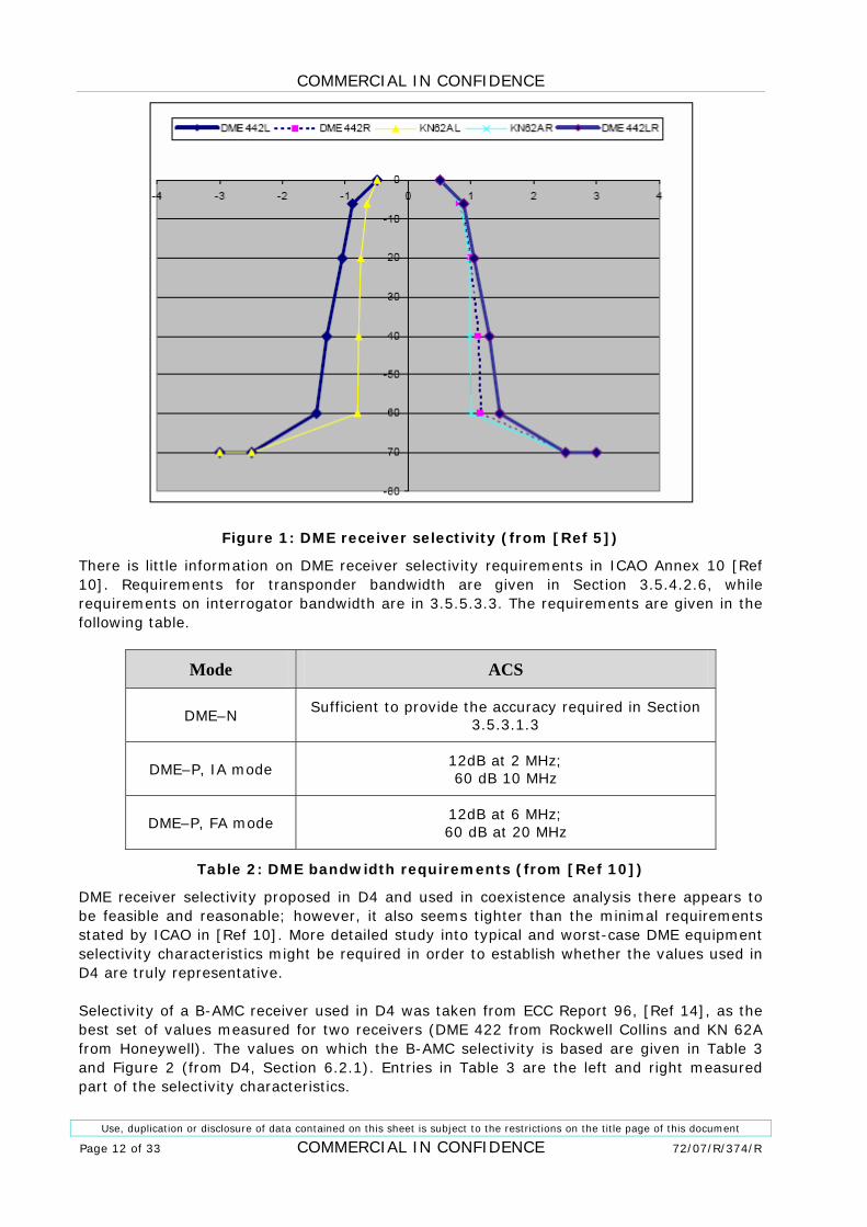
Figure 1: DME receiver selectivity (from [Ref 5])
There is little information on DME receiver selectivity requirements in ICAO Annex 10 1[Ref 10]. Requirements for transponder bandwidth are given in Section 3.5.4.2.6, while requirements on interrogator bandwidth are in 3.5.5.3.3. The requirements are given in the following table.
Mode ACS
DME–N Sufficient to provide the accuracy required in Section
3.5.3.1.3
DME–P, IA mode 12dB at 2 MHz; 60 dB 10 MHz
DME–P, FA mode 12dB at 6 MHz; 60 dB at 20 MHz
Table 2: DME bandwidth requirements (from 1[Ref 10])
DME receiver selectivity proposed in D4 and used in coexistence analysis there appears to be feasible and reasonable; however, it also seems tighter than the minimal requirements stated by ICAO in 1[Ref 10]. More detailed study into typical and worst-case DME equipment selectivity characteristics might be required in order to establish whether the values used in D4 are truly representative.
Selectivity of a B-AMC receiver used in D4 was taken from ECC Report 96, 1[Ref 14], as the best set of values measured for two receivers (DME 422 from Rockwell Collins and KN 62A from Honeywell). The values on which the B-AMC selectivity is based are given in 1Table 3 and 1Figure 2 (from D4, Section 6.2.1). Entries in 1Table 3 are the left and right measured part of the selectivity characteristics.

COMMERCIAL IN CONFIDENCE
Use, duplication or disclosure of data contained on this sheet is subject to the restrictions on the title page of this document
72/07/R/374/R COMMERCIAL IN CONFIDENCE Page 13 of 33
Table 3: Representative B-AMC IF selectivity (from 1[Ref 5])
Figure 2: Assumed B-AMC IF selectivity (from 1[Ref 5])
The values for B-AMC receiver selectivity are in D4 based on the best set of values, which is the left side of the selectivity curve for KN62A (row KN62AL in 1Table 3). The values for KN2AL are accepted as a selectivity of a B-AMC receiver below the carrier frequency, and mirrored values are accepted above the carrier. However, it may be that the difference between the entries KN2AL and KN2AR is caused by an uncompensated frequency offset of 100 kHz in measurements, and the correct values for DME selectivity should be mean values between KN2AL and KN2AR. Values of such selectivity characteristics are given in 1Table 4.
Attenuation (dB) 0 6 20 40 60 70 70 Frequency offset (MHz) 0.3 0.54 0.67 0.69 0.7 2.5 3
Table 4: Modified B-AMC receiver selectivity
It should also be noted that, while these selectivity characteristics are clearly realisable, receiver selectivity masks that will eventually be adopted as part of the B-AMC system performance requirements probably should not be made excessively tight, as this may have impact on equipment cost. It seems that the selected receiver has a one-sided 3 dB bandwidth of 0.375 MHz, and achieves 60 dB of selectivity at 0.6 MHz offset, which implies an IF filter roll-off of 100 dB/octave.
COMMERCIAL IN CONFIDENCE
Use, duplication or disclosure of data contained on this sheet is subject to the restrictions on the title page of this document
Page 14 of 33 COMMERCIAL IN CONFIDENCE 72/07/R/374/R
3 INTERFERENCE LINK BUDGET
3.1 FREQUENCY ALLOCATION AND INTERFERENCE SCENARIOS
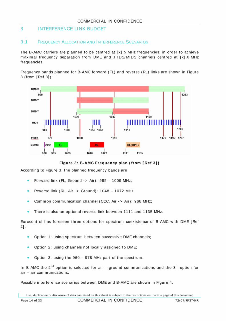
The B-AMC carriers are planned to be centred at [x].5 MHz frequencies, in order to achieve maximal frequency separation from DME and JTIDS/MIDS channels centred at [x].0 MHz frequencies.
Frequency bands planned for B-AMC forward (FL) and reverse (RL) links are shown in 1Figure 3 (from 1[Ref 3]).
Figure 3: B-AMC Frequency plan (from 1[Ref 3])
According to 1Figure 3, the planned frequency bands are
• Forward link (FL, Ground -> Air): 985 – 1009 MHz;
• Reverse link (RL, Air -> Ground): 1048 – 1072 MHz;
• Common communication channel (CCC, Air -> Air): 968 MHz;
• There is also an optional reverse link between 1111 and 1135 MHz.
Eurocontrol has foreseen three options for spectrum coexistence of B-AMC with DME 1[Ref 2]:
• Option 1: using spectrum between successive DME channels;
• Option 2: using channels not locally assigned to DME;
• Option 3: using the 960 – 978 MHz part of the spectrum.
In B-AMC the 2nd option is selected for air – ground communications and the 3rd option for air – air communications.
Possible interference scenarios between DME and B-AMC are shown in 1Figure 4.

COMMERCIAL IN CONFIDENCE
Use, duplication or disclosure of data contained on this sheet is subject to the restrictions on the title page of this document
72/07/R/374/R COMMERCIAL IN CONFIDENCE Page 15 of 33
Figure 4: Interference scenarios between B-AMC and DME
3.2 ANALYSIS METHODOLOGY
When out-of-band or spurious emissions of the interfering system fall into the receive band of the interfered system, interference will cause degradation of performance of the victim system. In B-AMC, interference will increase the error rate on the link and reduce channel capacity; in DME, this type of interference will appear as loss of DME receiver sensitivity and range.
Coexistence between the two systems (e.g. B-AMC and DME) can be achieved if the separation between them in frequency and distance is sufficient. The methodology to calculate the necessary separation implemented here is based no ITU-R Recommendation SM.337-4, 1[Ref 13].
The following equation can be used to calculate the interference power getting into the interfered receiver:
( ) ( )fFDRdLGGPI bRTT Δ−−++= (1)
Where
PT is interferer transmitter power,
GT is gain of interferer antenna in direction of receiver,
GR is gain of receiver antenna in direction of interferer,
Lb(d) is transmission loss for separation distance d, and
FDR(Δf) frequency dependant rejection for frequency separation Δf.
The critical factor in this equation is frequency dependant rejection (FDR). It can be calculated as
( ) ( )fOFROTRfFDR Δ+=Δ (2)

COMMERCIAL IN CONFIDENCE
Use, duplication or disclosure of data contained on this sheet is subject to the restrictions on the title page of this document
Page 16 of 33 COMMERCIAL IN CONFIDENCE 72/07/R/374/R
Where
OTR is on-tune rejection caused by interferer having wider bandwidth than the interfered receiver. The value of OTR should be calculated as the ratio of bandwidths, with 20 log if the interference is pulsed (e.g. DME) and 10 log if the interference is continuous and modulated.
OFR(Δf) is off-frequency rejection of the interfered system, defined by out-of-band emission spectrum of the interferer and IF response of the interfered system,
( )( ) ( )
( ) ( )∫∫
∞
=
∞
=
Δ+=Δ
dfffHfP
dffHfPfOFR
2
2
(3)
Where
P(f) is PSD of the interfering system, and
|H(f)| is IF selectivity of the interfered system.
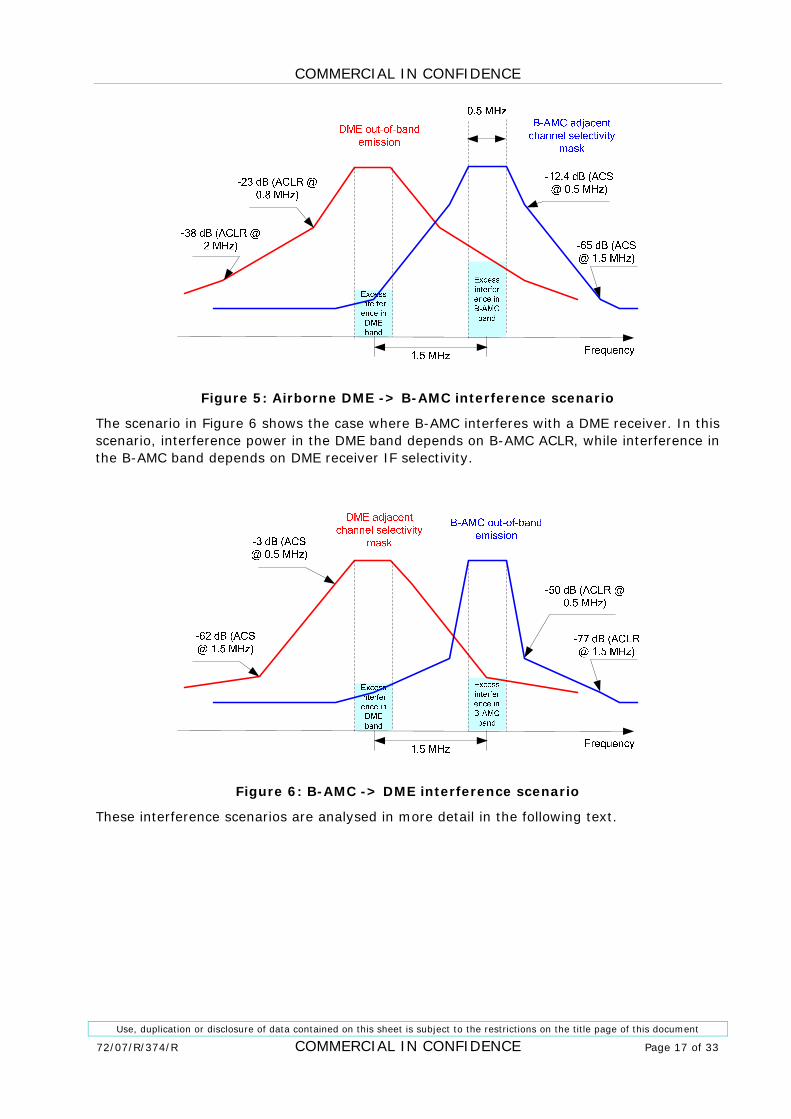
3.3 OFF-FREQUENCY REJECTION
In most practical cases, value of the integral in the denominator in equation ( 13) is dominated by two frequency ranges: one where P(f) has a maximum, and the other where |H(f-Δf)| has a maximum. In other words, total interference power in the off-tune scenario is dominated by the power in the interferer’s band and the power in the interfered system’s band:
bandAMCBbandDME III −+≅ (4)
This approach to off-frequency rejection is useful because it shows which interference mechanism dominates the out-of-band interference, and where improvements need to be made if total out-of-band interference needs to be reduced. For example, if in equation (14) the DME band interference is dominant, then interference can be reduced by improving B-AMC adjacent channel leakage ratio (ACLR), if interference is originating in B-AMC, or B-AMC adjacent channel selectivity (ACS), if DME is the interferer; this can be achieved e.g. by tighter RF filtering.
1Figure 5 illustrates a case when DME transmitter interferes with a B-AMC receiver. In this case, interference in the B-AMC band is defined by spurious emissions of the DME, while interference in the DME band depends on B-AMC adjacent channel selectivity.
COMMERCIAL IN CONFIDENCE
Use, duplication or disclosure of data contained on this sheet is subject to the restrictions on the title page of this document
72/07/R/374/R COMMERCIAL IN CONFIDENCE Page 17 of 33
Figure 5: Airborne DME -> B-AMC interference scenario
The scenario in 1Figure 6 shows the case where B-AMC interferes with a DME receiver. In this scenario, interference power in the DME band depends on B-AMC ACLR, while interference in the B-AMC band depends on DME receiver IF selectivity.
Figure 6: B-AMC -> DME interference scenario
These interference scenarios are analysed in more detail in the following text.
COMMERCIAL IN CONFIDENCE
Use, duplication or disclosure of data contained on this sheet is subject to the restrictions on the title page of this document
Page 18 of 33 COMMERCIAL IN CONFIDENCE 72/07/R/374/R
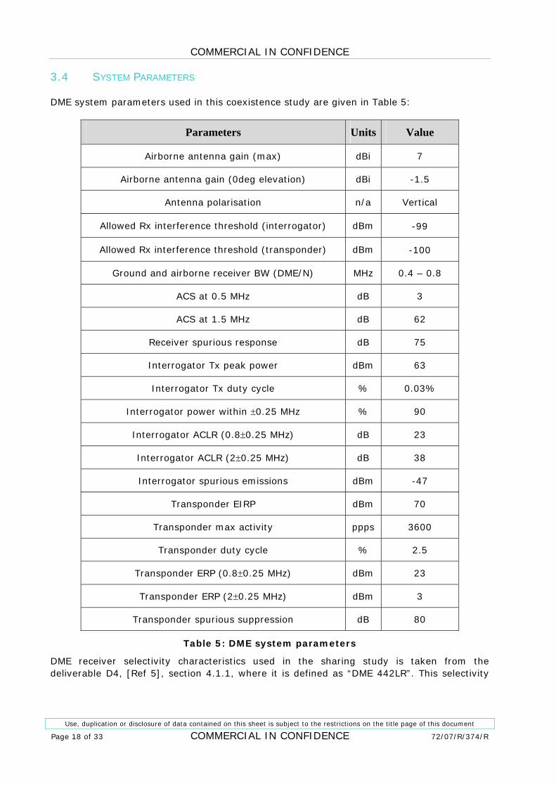
3.4 SYSTEM PARAMETERS
DME system parameters used in this coexistence study are given in 1Table 5:
Parameters Units Value
Airborne antenna gain (max) dBi 7
Airborne antenna gain (0deg elevation) dBi -1.5
Antenna polarisation n/a Vertical
Allowed Rx interference threshold (interrogator) dBm -99
Allowed Rx interference threshold (transponder) dBm -100
Ground and airborne receiver BW (DME/N) MHz 0.4 – 0.8
ACS at 0.5 MHz dB 3
ACS at 1.5 MHz dB 62
Receiver spurious response dB 75
Interrogator Tx peak power dBm 63
Interrogator Tx duty cycle % 0.03%
Interrogator power within ±0.25 MHz % 90
Interrogator ACLR (0.8±0.25 MHz) dB 23
Interrogator ACLR (2±0.25 MHz) dB 38
Interrogator spurious emissions dBm -47
Transponder EIRP dBm 70
Transponder max activity ppps 3600
Transponder duty cycle % 2.5
Transponder ERP (0.8±0.25 MHz) dBm 23
Transponder ERP (2±0.25 MHz) dBm 3
Transponder spurious suppression dB 80
Table 5: DME system parameters
DME receiver selectivity characteristics used in the sharing study is taken from the deliverable D4, [Ref 5], section 4.1.1, where it is defined as “DME 442LR”. This selectivity
COMMERCIAL IN CONFIDENCE
Use, duplication or disclosure of data contained on this sheet is subject to the restrictions on the title page of this document
72/07/R/374/R COMMERCIAL IN CONFIDENCE Page 19 of 33
characteristic is shown in Figure 1 and its values are given in Table 6 for different frequency offsets from the DME carrier.
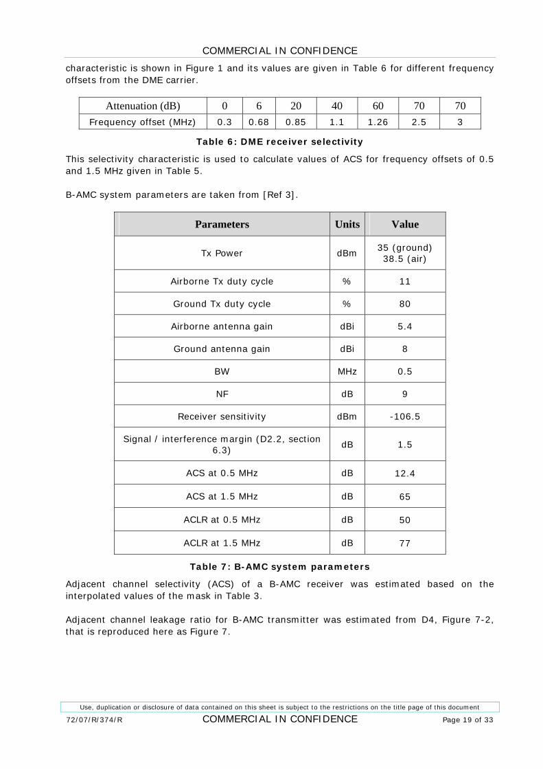
Attenuation (dB) 0 6 20 40 60 70 70 Frequency offset (MHz) 0.3 0.68 0.85 1.1 1.26 2.5 3
Table 6: DME receiver selectivity
This selectivity characteristic is used to calculate values of ACS for frequency offsets of 0.5 and 1.5 MHz given in 1Table 5.
B-AMC system parameters are taken from 1[Ref 3].
Parameters Units Value
Tx Power dBm 35 (ground) 38.5 (air)
Airborne Tx duty cycle % 11
Ground Tx duty cycle % 80
Airborne antenna gain dBi 5.4
Ground antenna gain dBi 8
BW MHz 0.5
NF dB 9
Receiver sensitivity dBm -106.5
Signal / interference margin (D2.2, section 6.3)
dB 1.5
ACS at 0.5 MHz dB 12.4
ACS at 1.5 MHz dB 65
ACLR at 0.5 MHz dB 50
ACLR at 1.5 MHz dB 77
Table 7: B-AMC system parameters
Adjacent channel selectivity (ACS) of a B-AMC receiver was estimated based on the interpolated values of the mask in 1Table 3.
Adjacent channel leakage ratio for B-AMC transmitter was estimated from D4, Figure 7-2, that is reproduced here as 1Figure 7.

COMMERCIAL IN CONFIDENCE
Use, duplication or disclosure of data contained on this sheet is subject to the restrictions on the title page of this document
Page 20 of 33 COMMERCIAL IN CONFIDENCE 72/07/R/374/R
Figure 7: B-AMC Tx spectral mask (from 1[Ref 5]).
Based on this mask, the ACLR was estimated as 50 dB for 0.5 MHz away (48 carriers away) and 77 dB for 1.5 MHz away (144 carriers away).
General system parameters are given in 1Table 8:
Parameters Units Value Notes Isolation between co-sited antennas on the
same side of the aircraft dB 35
Both on top or at the bottom of the aircraft, typical case.
Isolation between co-sited antennas on the
ground dB 20
Values between 20 and 40dB typically experienced
Polarisation mismatch loss
dB 3 E.g. between vertical and right-hand circular polarisation
Receiver input 1dB compression point
(1dBCP) dBm -10
Includes effects of LNA and mixer saturation and intermediate RF filter stage.
Receiver 3rd order input intercept point (IIP3)
dBm 0 1dBCP+10dB
DME interference protection margin
dB 6 Additional S/I margin for safety-critical systems. Includes a back-off margin
Apportionment of interference to all the interference sources
dB 6 Additional S/I margin to accommodate other sources of interference
Table 8: General parameters
COMMERCIAL IN CONFIDENCE
Use, duplication or disclosure of data contained on this sheet is subject to the restrictions on the title page of this document
72/07/R/374/R COMMERCIAL IN CONFIDENCE Page 21 of 33
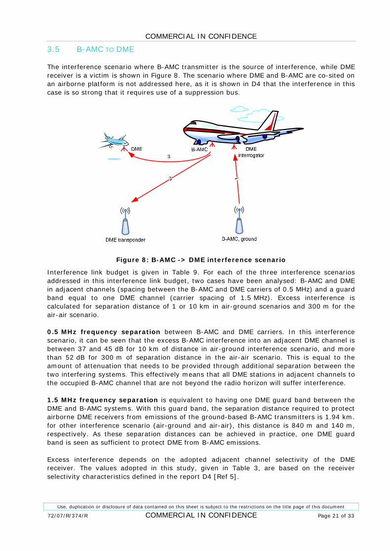
3.5 B-AMC TO DME
The interference scenario where B-AMC transmitter is the source of interference, while DME receiver is a victim is shown in 1Figure 8. The scenario where DME and B-AMC are co-sited on an airborne platform is not addressed here, as it is shown in D4 that the interference in this case is so strong that it requires use of a suppression bus.
Figure 8: B-AMC -> DME interference scenario
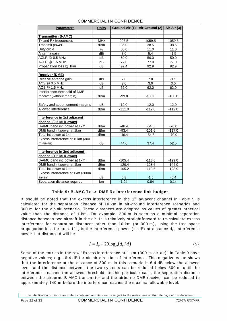
Interference link budget is given in 1Table 9. For each of the three interference scenarios addressed in this interference link budget, two cases have been analysed: B-AMC and DME in adjacent channels (spacing between the B-AMC and DME carriers of 0.5 MHz) and a guard band equal to one DME channel (carrier spacing of 1.5 MHz). Excess interference is calculated for separation distance of 1 or 10 km in air-ground scenarios and 300 m for the air-air scenario.
0.5 MHz frequency separation between B-AMC and DME carriers. In this interference scenario, it can be seen that the excess B-AMC interference into an adjacent DME channel is between 37 and 45 dB for 10 km of distance in air-ground interference scenario, and more than 52 dB for 300 m of separation distance in the air-air scenario. This is equal to the amount of attenuation that needs to be provided through additional separation between the two interfering systems. This effectively means that all DME stations in adjacent channels to the occupied B-AMC channel that are not beyond the radio horizon will suffer interference.
1.5 MHz frequency separation is equivalent to having one DME guard band between the DME and B-AMC systems. With this guard band, the separation distance required to protect airborne DME receivers from emissions of the ground-based B-AMC transmitters is 1.94 km. for other interference scenario (air-ground and air-air), this distance is 840 m and 140 m, respectively. As these separation distances can be achieved in practice, one DME guard band is seen as sufficient to protect DME from B-AMC emissions.
Excess interference depends on the adopted adjacent channel selectivity of the DME receiver. The values adopted in this study, given in Table 3, are based on the receiver selectivity characteristics defined in the report D4 [Ref 5].
COMMERCIAL IN CONFIDENCE
Use, duplication or disclosure of data contained on this sheet is subject to the restrictions on the title page of this document
Page 22 of 33 COMMERCIAL IN CONFIDENCE 72/07/R/374/R
Parameters Units Ground-Air (1) Air-Ground (2) Air-Air (3)
Transmitter (B-AMC)Tx and Rx frequencies MHz 996.5 1059.5 1059.5Transmit power dBm 35.0 38.5 38.5Duty cycle % 80.0 11.0 11.0Antenna gain dBi 8.0 5.4 -1.5ACLR @ 0.5 MHz dB 50.0 50.0 50.0ACLR @ 1.5 MHz dB 77.0 77.0 77.0Propagation loss @ 1km dB 92.4 92.9 92.9
Receiver (DME)Receive antenna gain dBi 7.0 7.0 -1.5ACS @ 0.5 MHz dB 3.0 3.0 3.0ACS @ 1.5 MHz dB 62.0 62.0 62.0Interference threshold of DME receiver (without margin) dBm -99.0 -100.0 -100.0
Safety and apportionment margins dB 12.0 12.0 12.0Allowed interference dBm -111.0 -112.0 -112.0
Interference in 1st adjacent channel (0.5 MHz away)B-AMC band int. power at 1km dBm -46.4 -54.6 -70.0DME band int.power at 1km dBm -93.4 -101.6 -117.0Total int.power at 1km dBm -46.4 -54.6 -70.0Excess interference at 10km (300 m air-air) dB 44.6 37.4 52.5
Interference in 2nd adjacent channel (1.5 MHz away)B-AMC band int. power at 1km dBm -105.4 -113.6 -129.0DME band int.power at 1km dBm -120.4 -128.6 -144.0Total int.power at 1km dBm -105.2 -113.5 -128.9Excess interference at 1km (300m air-air) dB 5.8 -1.5 -6.4Separation distance required km 1.94 0.84 0.14
Table 9: B-AMC Tx -> DME Rx interference link budget
It should be noted that the excess interference in the 1st adjacent channel in Table 9 is calculated for the separation distance of 10 km in air-ground interference scenarios and 300 m for the air-air scenario. These distances are adopted as values of greater practical value than the distance of 1 km. For example, 300 m is seen as a minimal separation distance between two aircraft in the air. It is relatively straightforward to re-calculate excess interference for separation distances other than 10 km (or 300 m), using the free space propagation loss formula. If I0 is the interference power (in dB) at distance d0, interference power I at distance d will be
( )ddII /log20 0100 += (5)
Some of the entries in the row “Excess interference at 1 km (300 m air-air)” in Table 9 have negative values; e.g. -6.4 dB for air-air direction of interference. This negative value shows that the interference at the distance of 300 m in this scenario is 6.4 dB below the allowed level, and the distance between the two systems can be reduced below 300 m until the interference reaches the allowed threshold. In this particular case, the separation distance between the airborne B-AMC transmitter and the airborne DME receiver can be reduced to approximately 140 m before the interference reaches the maximal allowable level.
COMMERCIAL IN CONFIDENCE
Use, duplication or disclosure of data contained on this sheet is subject to the restrictions on the title page of this document
72/07/R/374/R COMMERCIAL IN CONFIDENCE Page 23 of 33
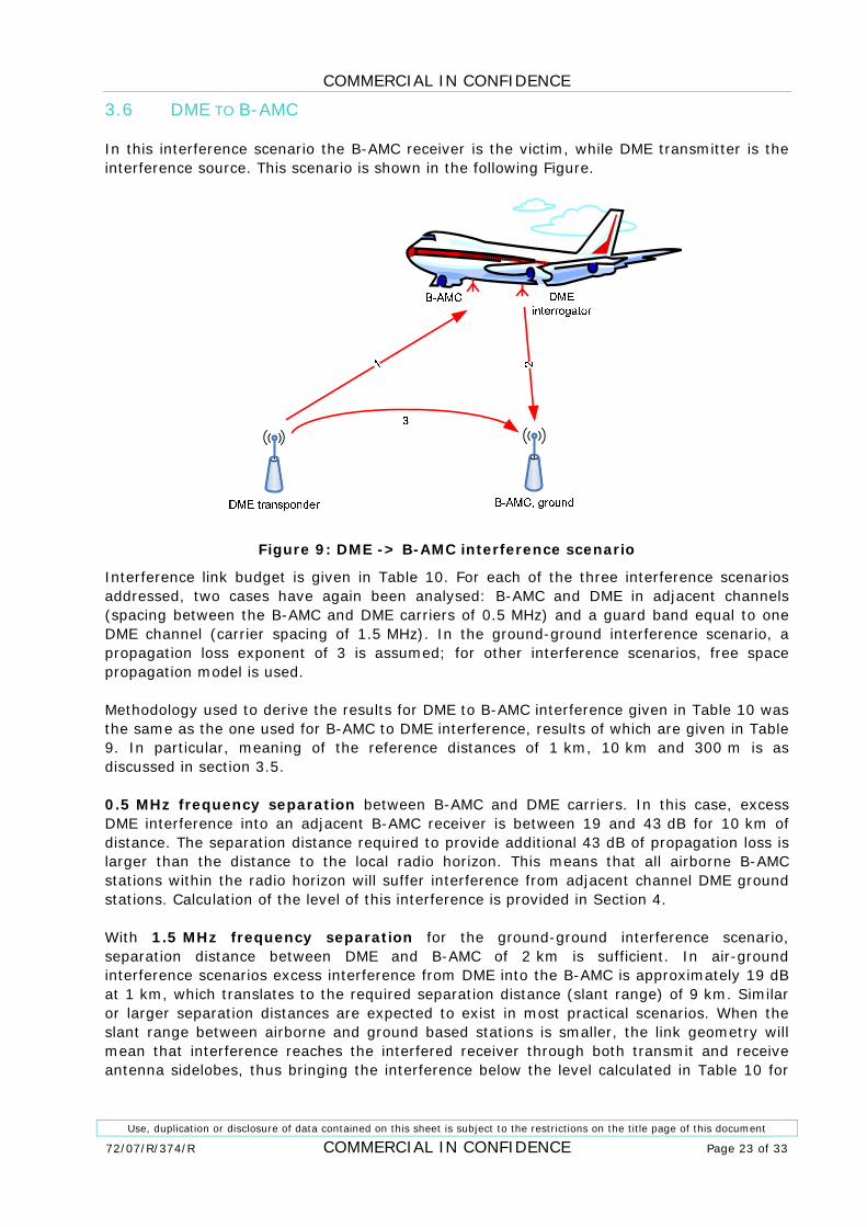
3.6 DME TO B-AMC
In this interference scenario the B-AMC receiver is the victim, while DME transmitter is the interference source. This scenario is shown in the following Figure.
Figure 9: DME -> B-AMC interference scenario
Interference link budget is given in 1Table 10. For each of the three interference scenarios addressed, two cases have again been analysed: B-AMC and DME in adjacent channels (spacing between the B-AMC and DME carriers of 0.5 MHz) and a guard band equal to one DME channel (carrier spacing of 1.5 MHz). In the ground-ground interference scenario, a propagation loss exponent of 3 is assumed; for other interference scenarios, free space propagation model is used.
Methodology used to derive the results for DME to B-AMC interference given in Table 10 was the same as the one used for B-AMC to DME interference, results of which are given in Table 9. In particular, meaning of the reference distances of 1 km, 10 km and 300 m is as discussed in section 3.5.
0.5 MHz frequency separation between B-AMC and DME carriers. In this case, excess DME interference into an adjacent B-AMC receiver is between 19 and 43 dB for 10 km of distance. The separation distance required to provide additional 43 dB of propagation loss is larger than the distance to the local radio horizon. This means that all airborne B-AMC stations within the radio horizon will suffer interference from adjacent channel DME ground stations. Calculation of the level of this interference is provided in Section 4.
With 1.5 MHz frequency separation for the ground-ground interference scenario, separation distance between DME and B-AMC of 2 km is sufficient. In air-ground interference scenarios excess interference from DME into the B-AMC is approximately 19 dB at 1 km, which translates to the required separation distance (slant range) of 9 km. Similar or larger separation distances are expected to exist in most practical scenarios. When the slant range between airborne and ground based stations is smaller, the link geometry will mean that interference reaches the interfered receiver through both transmit and receive antenna sidelobes, thus bringing the interference below the level calculated in Table 10 for

COMMERCIAL IN CONFIDENCE
Use, duplication or disclosure of data contained on this sheet is subject to the restrictions on the title page of this document
Page 24 of 33 COMMERCIAL IN CONFIDENCE 72/07/R/374/R
the worst case (maximal antenna gain) scenario. Therefore, the frequency separation of 1.5 GHz is seen as sufficient to enable operation of B-AMC in presence of DME interference.
Parameters UnitsGround-Air
(1) Air-Ground (2)Ground-
ground (3)
Transmitter (DME)Tx and Rx frequencies MHz 996.5 1059.5 996.5EIRP dBm 70.0 63.0 70.0Tx duty cycle % 2.5 0.03 2.5EIRP @ 0.5 MHz dBm 30.2 43.8 30.2EIRP @ 1.5 MHz dBm 13.5 31.3 13.5Propagation loss at 1km dB 92.4 92.9 102.4
Receiver (B-AMC)Receive antenna gain dBi 5.4 8.0 5.4Receiver bandwidth MHz 0.5 0.5 0.5ACS @ 0.5 MHz dB 12.4 12.4 12.4ACS @ 1.5 MHz dB 65.0 65.0 65.0Receiver sensitivity dBm -106.5 -106.5 -106.5Interference margin dB 1.5 1.5 1.5Allowed interference dBm -108.0 -108.0 -108.0
Interference in 1st adjacent channel (0.5 MHz away)DME band int. power at 1km dBm -45.4 -69.6 -55.4B-AMC band int.power at 1km dBm -72.8 -76.4 -82.8Total int.power at 1km dBm -45.4 -68.8 -55.4Excess interference at 10 km dB 42.6 19.2 22.6
Interference in 2nd adjacent channel (1.5 MHz away)DME band int. power at 1km dBm -98.0 -122.2 -108.0B-AMC band int.power at 1km dBm -89.5 -88.9 -99.5Total int.power at 1km dBm -88.9 -88.9 -98.9Excess interference at 1 km dB 19.1 19.1 9.1Separation distance required km 9.0 9.0 2.0
Table 10: DME Tx -> B-AMC Rx interference link budget
3.7 CONCLUSIONS
Based on the interference link budget analysis, the following conclusions can be drawn:
• One DME guard band is sufficient to protect DME and B-AMC systems from mutual interference;
• Operation of DME and B-AMC in adjacent channels (without a guard band) does not seem possible in the same geographical area.
The second conclusion is based on interference link budgets, and is therefore addressing a worst-case scenario. For this reason, a more realistic estimation of interference that existing DME stations in Europe would cause to an airborne B-AMC receiver without guard bands is provided in the next section.

COMMERCIAL IN CONFIDENCE
Use, duplication or disclosure of data contained on this sheet is subject to the restrictions on the title page of this document
72/07/R/374/R COMMERCIAL IN CONFIDENCE Page 25 of 33
4 ANALYSIS OF DME TRANSPONDER INTERFERENCE IN EUROPE
Successful deployment of B-AMC in L band depends on whether it is possible for this system to share the L band with existing radionavigation systems, primarily with SSR and DME. Coexistence with SSR is enabled through an adoption of the frequency plan for B-AMC shown in 1Figure 3, i.e. by providing sufficient guard bands between the SSR and DME bands.
The question of coexistence of B-AMC with DME is less clear, as it depends on frequency coordination between the two systems. In particular, the most promising approach is Option 2, defined by Eurocontrol as using B-AMC channels in the “quietest” part of DME spectrum locally.
In this section, the feasibility of this concept is examined by calculating the spatial distribution of interference that would be caused by DME transponders to an airborne B-AMC receiver, assuming ideal frequency coordination between DME and B-AMC systems. The calculations were based on the table of DME channel allocation 1[Ref 8], provided to Roke by Eurocontrol as an input to an earlier project 1[Ref 9]. Snapshot of the table of allocations is shown in 1Figure 10.
Figure 10: List of DME stations in Europe (from 1[Ref 8]).
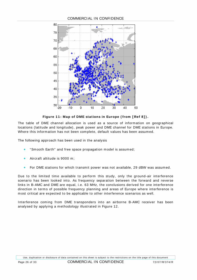
A map of DME stations in Europe using DME channels 23X to 49X, based on the information given in this table, is shown in the following Figure. These channels are chosen because they could appear as adjacent channel interference to an airborne B-AMC receiver if frequency plan shown in 1Figure 3 is used for forward links.
COMMERCIAL IN CONFIDENCE
Use, duplication or disclosure of data contained on this sheet is subject to the restrictions on the title page of this document
Page 26 of 33 COMMERCIAL IN CONFIDENCE 72/07/R/374/R
Figure 11: Map of DME stations in Europe (from 1[Ref 8]).
The table of DME channel allocation is used as a source of information on geographical locations (latitude and longitude), peak power and DME channel for DME stations in Europe. Where this information has not been complete, default values has been assumed.
The following approach has been used in the analysis
• “Smooth Earth” and free space propagation model is assumed;
• Aircraft altitude is 9000 m;
• For DME stations for which transmit power was not available, 29 dBW was assumed.
Due to the limited time available to perform this study, only the ground-air interference scenario has been looked into. As frequency separation between the forward and reverse links in B-AMC and DME are equal, i.e. 63 MHz, the conclusions derived for one interference direction in terms of possible frequency planning and areas of Europe where interference is most critical are expected to be applicable to other interference scenarios as well.
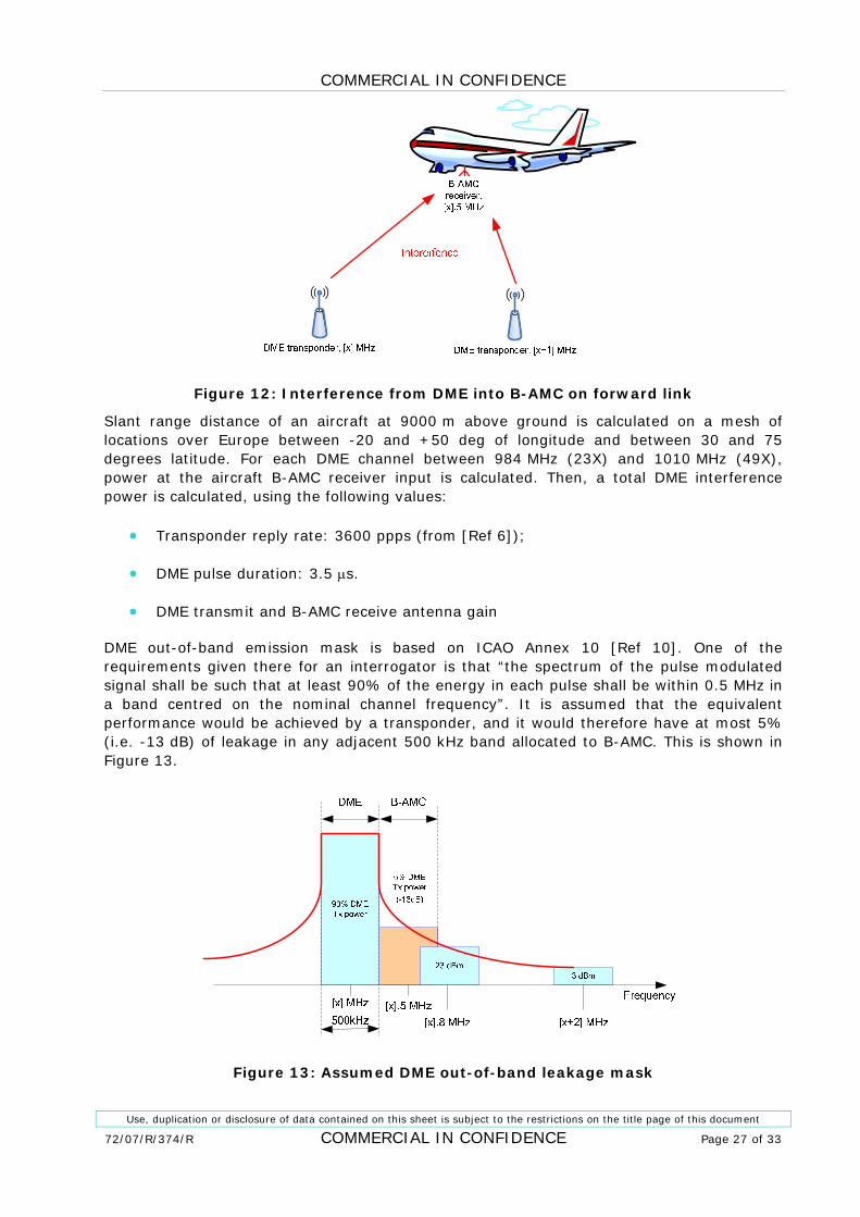
Interference coming from DME transponders into an airborne B-AMC receiver has been analysed by applying a methodology illustrated in Figure 12.
COMMERCIAL IN CONFIDENCE
Use, duplication or disclosure of data contained on this sheet is subject to the restrictions on the title page of this document
72/07/R/374/R COMMERCIAL IN CONFIDENCE Page 27 of 33
Figure 12: Interference from DME into B-AMC on forward link
Slant range distance of an aircraft at 9000 m above ground is calculated on a mesh of locations over Europe between -20 and +50 deg of longitude and between 30 and 75 degrees latitude. For each DME channel between 984 MHz (23X) and 1010 MHz (49X), power at the aircraft B-AMC receiver input is calculated. Then, a total DME interference power is calculated, using the following values:
• Transponder reply rate: 3600 ppps (from 1[Ref 6]);
• DME pulse duration: 3.5 μs.
• DME transmit and B-AMC receive antenna gain
DME out-of-band emission mask is based on ICAO Annex 10 1[Ref 10]. One of the requirements given there for an interrogator is that “the spectrum of the pulse modulated signal shall be such that at least 90% of the energy in each pulse shall be within 0.5 MHz in a band centred on the nominal channel frequency”. It is assumed that the equivalent performance would be achieved by a transponder, and it would therefore have at most 5% (i.e. -13 dB) of leakage in any adjacent 500 kHz band allocated to B-AMC. This is shown in Figure 13.
Figure 13: Assumed DME out-of-band leakage mask
COMMERCIAL IN CONFIDENCE
Use, duplication or disclosure of data contained on this sheet is subject to the restrictions on the title page of this document
Page 28 of 33 COMMERCIAL IN CONFIDENCE 72/07/R/374/R
For every potential B-AMC channel at [x].5 MHz, there is a possibility of interference coming from the DME transponders at frequencies [x] and [x+1] MHz; contribution from channels further away in frequency have been considered negligible in this analysis.
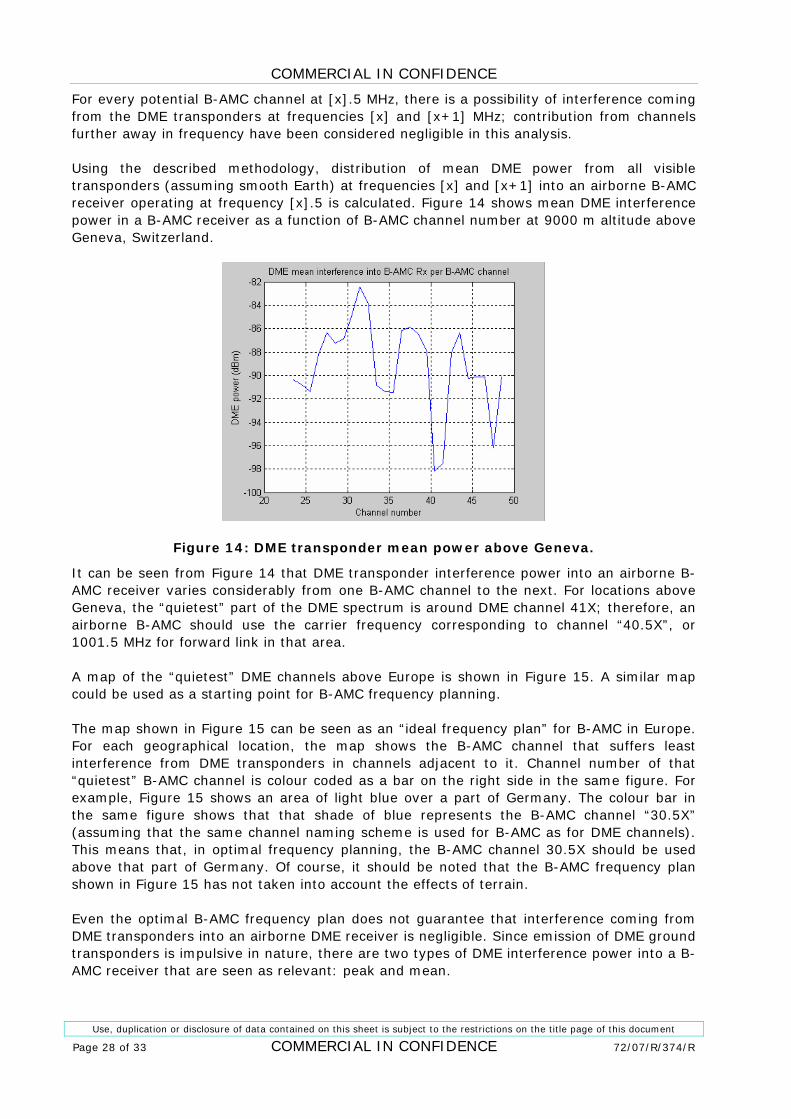
Using the described methodology, distribution of mean DME power from all visible transponders (assuming smooth Earth) at frequencies [x] and [x+1] into an airborne B-AMC receiver operating at frequency [x].5 is calculated. 1Figure 14 shows mean DME interference power in a B-AMC receiver as a function of B-AMC channel number at 9000 m altitude above Geneva, Switzerland.
Figure 14: DME transponder mean power above Geneva.
It can be seen from 1Figure 14 that DME transponder interference power into an airborne B-AMC receiver varies considerably from one B-AMC channel to the next. For locations above Geneva, the “quietest” part of the DME spectrum is around DME channel 41X; therefore, an airborne B-AMC should use the carrier frequency corresponding to channel “40.5X”, or 1001.5 MHz for forward link in that area.
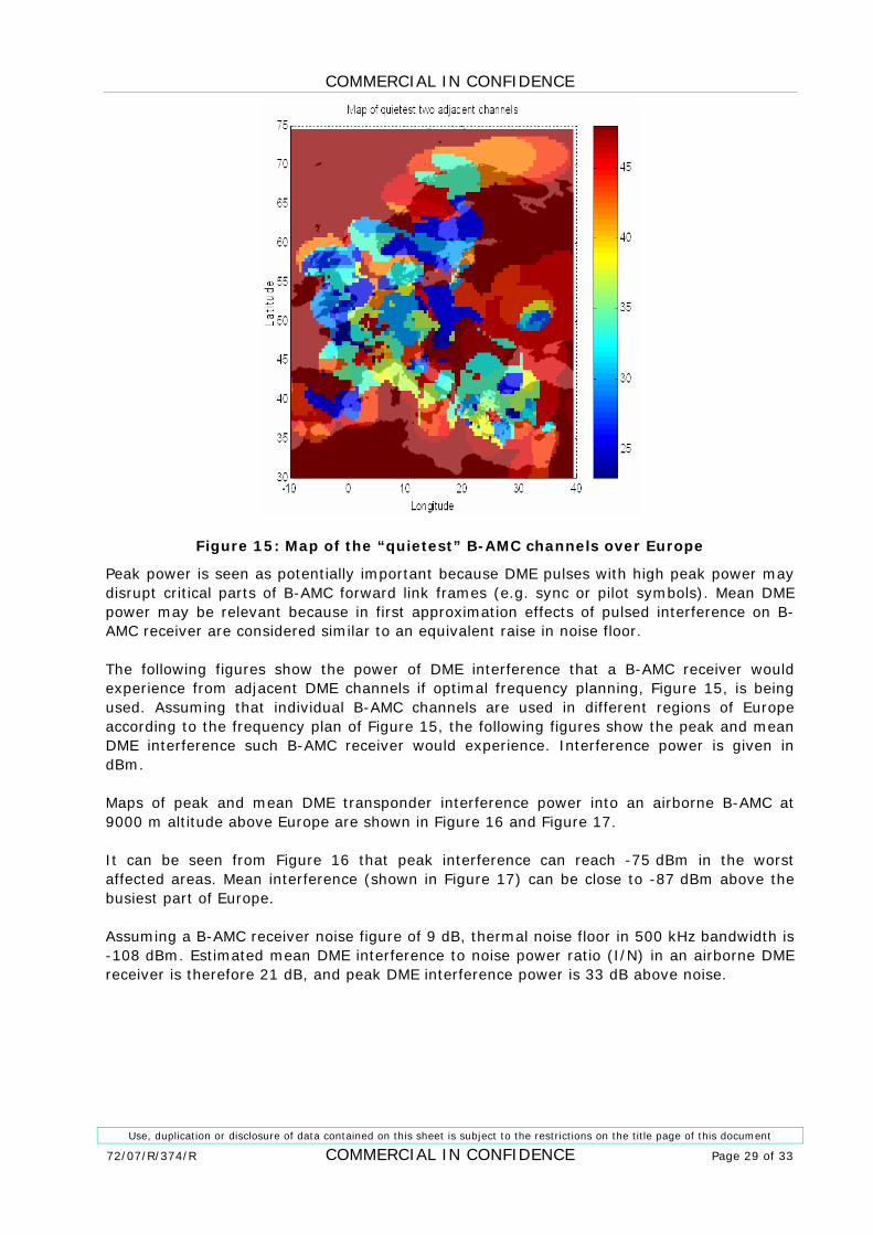
A map of the “quietest” DME channels above Europe is shown in 1Figure 15. A similar map could be used as a starting point for B-AMC frequency planning.
The map shown in Figure 15 can be seen as an “ideal frequency plan” for B-AMC in Europe. For each geographical location, the map shows the B-AMC channel that suffers least interference from DME transponders in channels adjacent to it. Channel number of that “quietest” B-AMC channel is colour coded as a bar on the right side in the same figure. For example, Figure 15 shows an area of light blue over a part of Germany. The colour bar in the same figure shows that that shade of blue represents the B-AMC channel “30.5X” (assuming that the same channel naming scheme is used for B-AMC as for DME channels). This means that, in optimal frequency planning, the B-AMC channel 30.5X should be used above that part of Germany. Of course, it should be noted that the B-AMC frequency plan shown in Figure 15 has not taken into account the effects of terrain.
Even the optimal B-AMC frequency plan does not guarantee that interference coming from DME transponders into an airborne DME receiver is negligible. Since emission of DME ground transponders is impulsive in nature, there are two types of DME interference power into a B-AMC receiver that are seen as relevant: peak and mean.
COMMERCIAL IN CONFIDENCE
Use, duplication or disclosure of data contained on this sheet is subject to the restrictions on the title page of this document
72/07/R/374/R COMMERCIAL IN CONFIDENCE Page 29 of 33
Figure 15: Map of the “quietest” B-AMC channels over Europe
Peak power is seen as potentially important because DME pulses with high peak power may disrupt critical parts of B-AMC forward link frames (e.g. sync or pilot symbols). Mean DME power may be relevant because in first approximation effects of pulsed interference on B-AMC receiver are considered similar to an equivalent raise in noise floor.
The following figures show the power of DME interference that a B-AMC receiver would experience from adjacent DME channels if optimal frequency planning, Figure 15, is being used. Assuming that individual B-AMC channels are used in different regions of Europe according to the frequency plan of Figure 15, the following figures show the peak and mean DME interference such B-AMC receiver would experience. Interference power is given in dBm.
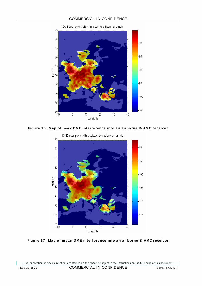
Maps of peak and mean DME transponder interference power into an airborne B-AMC at 9000 m altitude above Europe are shown in 1Figure 16 and 1Figure 17.
It can be seen from 1Figure 16 that peak interference can reach -75 dBm in the worst affected areas. Mean interference (shown in 1Figure 17) can be close to -87 dBm above the busiest part of Europe.
Assuming a B-AMC receiver noise figure of 9 dB, thermal noise floor in 500 kHz bandwidth is -108 dBm. Estimated mean DME interference to noise power ratio (I/N) in an airborne DME receiver is therefore 21 dB, and peak DME interference power is 33 dB above noise.
COMMERCIAL IN CONFIDENCE
Use, duplication or disclosure of data contained on this sheet is subject to the restrictions on the title page of this document
Page 30 of 33 COMMERCIAL IN CONFIDENCE 72/07/R/374/R
Figure 16: Map of peak DME interference into an airborne B-AMC receiver
Figure 17: Map of mean DME interference into an airborne B-AMC receiver
COMMERCIAL IN CONFIDENCE
Use, duplication or disclosure of data contained on this sheet is subject to the restrictions on the title page of this document
72/07/R/374/R COMMERCIAL IN CONFIDENCE Page 31 of 33
5 CONCLUSIONS AND RECOMMENDATIONS
This report contains the results of an analysis of L-band sharing issues between a B-AMC implementation of the future air – ground communication system (FCS) and DME systems. The issues considered are:
• Discussion of some issues regarding the selection of OFDM as a technology for FCS;
• Discussion of some B-AMC assumptions adopted in 1[Ref 1] and 2[Ref 5];
• Development of interference link budgets between B-AMC and DME that addressed the worst-case scenarios; and
• Initial assessment of interference coming from existing DME transponders in Europe into an airborne B-AMC receiver.
The conclusions of the performed analysis are:
• It is not clear whether benefits of OFDM on the reverse link overweight the need for a highly linear airborne power amplifier;
• One DME guard band is sufficient to protect DME and B-AMC from mutual interference, assuming the interference threshold given in [Ref 3] for B-AMC receivers;
• Without a guard band, existing DME stations in Europe could cause up to -75 dBm peak and -87 dBm mean interference into a B-AMC receiver at 9000 m altitude, even with optimal frequency planning.
Based on these results, our recommendations to Eurocontrol are:
• To examine methods to reduce peak-to-mean ratio of OFDM in the reverse link, e.g. by using a single carrier FDMA or a similar technique;
• To investigate whether key FCS system parameters could be selected in line with a commercial OFDM standard (e.g. WiMAX) to an extent that would facilitate partial reuse of COTS solutions, and
• To investigate the feasibility of frequency coordination between B-AMC and DME based on the existing DME frequency allocation in Europe and including the effects of terrain, in order to achieve the required separation distances and guard bands between the two systems.
Roke also supports the suggestion made in B-AMC Project Deliverable D4 2[Ref 5] calling for the establishment of common assumptions, metrics and interference criteria for all candidate FCS technologies that would enable objective comparison between them.
COMMERCIAL IN CONFIDENCE
Use, duplication or disclosure of data contained on this sheet is subject to the restrictions on the title page of this document
Page 32 of 33 COMMERCIAL IN CONFIDENCE 72/07/R/374/R
6 REFERENCES
[Ref 1] AMC Project Deliverable D1, Draft 1.0, 14/08/2007
[Ref 2] Report D 2.1, B-AMC System High Level Description, 17/08/2007
[Ref 3] Report D 2.2, B-AMC Operating Concept and Deployment Scenarios, 24/08/2007
[Ref 4] Report D 3, System Specification Including Standardization and Certification Considerations, 14/08/2007
[Ref 5] Report D4, B-AMC Interference Analysis and Spectrum Requirements
[Ref 6] Report D5, Expected B-AMC System Performance, 24/09/2007
[Ref 7] Report D6, B-AMC Aircraft Integration and Ground Infrastructure, 17/08/2007
[Ref 8] ICAOCOM_COM3_ASSIGNMENT.xls
[Ref 9] Roke, L-Band 3G Ground-Air Communication System Interference Study, 72/06/R/319/R, December 2006.
[Ref 10] ICAO Annex 10, Volume I, Radio Navigation Aids
[Ref 11] Peter Hoeher and Erik Haas, “Aeronautical Channel Modelling at VHF-Band”, Vehicular Technology Conference, 1999
[Ref 12] J.G. Andrews at.al, Fundamentals of WiMAX, Prentice-Hall, 2007
[Ref 13] ITU-R Recommendation SM.337-4, Frequency and Distance Separations
[Ref 14] ECC Report 96, Compatibility Between UMTS 900/1800 and Systems Operating in Adjacent Bands, March 2007.
7 GLOSSARY
ACLR Adjacent Channel Leakage Ratio
ACS Adjacent Channel Selectivity
COTS Commercial Off-the-Shelf
FCS Future air-ground Communication System
FDR Frequency Dependant Rejection
OFDM Orthogonal Frequency Division Multiplexing
OFR Off-Frequency Rejection
OTR On-Tune Rejection
COMMERCIAL IN CONFIDENCE
Use, duplication or disclosure of data contained on this sheet is subject to the restrictions on the title page of this document
72/07/R/374/R COMMERCIAL IN CONFIDENCE Page 33 of 33
This page intentionally left blank
COMMERCIAL IN CONFIDENCE
COMMERCIAL IN CONFIDENCE