DJ-20 8 Jointer - Delta Machinery
28
INSTRUCTION MANUAL DJ-20 8" Jointer (Model 37-365X, 37-680 and 37-680X) PART NO. A06586 - 08-23-04 Copyright © 2004 Delta Machinery To learn more about DELTA MACHINERY visit our website at: www.deltamachinery.com. For Parts, Service, Warranty or other Assistance, please call 1-800-223-7278 (In Canada call 1-800-463-3582).
Transcript of DJ-20 8 Jointer - Delta Machinery

INS
TRU
CTIO
NM
AN
UA
LDJ-20
8" Jointer(Model 37-365X, 37-680 and 37-680X)
PART NO. A06586 - 08-23-04Copyright © 2004 Delta Machinery
To learn more about DELTA MACHINERY visit our website at: www.deltamachinery.com.
For Parts, Service, Warranty or other Assistance,
please call 1-800-223-7278 (In Canada call 1-800-463-3582).

2
TABLE OF CONTENTS
Read and understand all warnings and operating instructions before using any tool or equipment. Whenusing tools or equipment, basic safety precautions should always be followed to reduce the risk of personal injury.Improper operation, maintenance or modification of tools or equipment could result in serious injury and propertydamage. There are certain applications for which tools and equipment are designed. Delta Machinery stronglyrecommends that this product NOT be modified and/or used for any application other than for which it was designed.
If you have any questions relative to its application DO NOT use the product until you have written Delta Machineryand we have advised you.
Online contact form at www.deltamachinery.com
Postal Mail: Technical Service ManagerDelta Machinery4825 Highway 45 NorthJackson, TN 38305
Information regarding the safe and proper operation of this tool is available from the following sources:
Power Tool Institute1300 Sumner Avenue, Cleveland, OH 44115-2851www.powertoolinstitute.org
National Safety Council1121 Spring Lake Drive, Itasca, IL 60143-3201
American National Standards Institute, 25 West 43rd Street, 4 floor, New York, NY 10036 www.ansi.orgANSI 01.1Safety Requirements for Woodworking Machines, and
the U.S. Department of Labor regulations www.osha.gov
IMPORTANT SAFETY INSTRUCTIONS
SAVE THESE INSTRUCTIONS!
IMPORTANT SAFETY INSTRUCTIONS . . . . . . . . . . . . . . . . . . . . . . . . . . . . . . . . . . . . . . . . . . . . . . . . . . . . . . . . . . .2SAFETY GUIDELINES . . . . . . . . . . . . . . . . . . . . . . . . . . . . . . . . . . . . . . . . . . . . . . . . . . . . . . . . . . . . . . . . . . . . . . . .3GENERAL SAFETY RULES . . . . . . . . . . . . . . . . . . . . . . . . . . . . . . . . . . . . . . . . . . . . . . . . . . . . . . . . . . . . . . . . . . . .4ADDITIONAL SPECIFIC SAFETY RULES . . . . . . . . . . . . . . . . . . . . . . . . . . . . . . . . . . . . . . . . . . . . . . . . . . . . . . . . .5FUNCTIONAL DESCRIPTION . . . . . . . . . . . . . . . . . . . . . . . . . . . . . . . . . . . . . . . . . . . . . . . . . . . . . . . . . . . . . . . . . .7CARTON CONTENTS . . . . . . . . . . . . . . . . . . . . . . . . . . . . . . . . . . . . . . . . . . . . . . . . . . . . . . . . . . . . . . . . . . . . . . . . .8ASSEMBLY . . . . . . . . . . . . . . . . . . . . . . . . . . . . . . . . . . . . . . . . . . . . . . . . . . . . . . . . . . . . . . . . . . . . . . . . . . . . . . .9-13OPERATION . . . . . . . . . . . . . . . . . . . . . . . . . . . . . . . . . . . . . . . . . . . . . . . . . . . . . . . . . . . . . . . . . . . . . . . . . . . .14-22TROUBLESHOOTING . . . . . . . . . . . . . . . . . . . . . . . . . . . . . . . . . . . . . . . . . . . . . . . . . . . . . . . . . . . . . . . . . . . . . . .22MAINTENANCE . . . . . . . . . . . . . . . . . . . . . . . . . . . . . . . . . . . . . . . . . . . . . . . . . . . . . . . . . . . . . . . . . . . . . . . . . .22-24SERVICE . . . . . . . . . . . . . . . . . . . . . . . . . . . . . . . . . . . . . . . . . . . . . . . . . . . . . . . . . . . . . . . . . . . . . . . . . . . . . . . . . .27ACCESSORIES . . . . . . . . . . . . . . . . . . . . . . . . . . . . . . . . . . . . . . . . . . . . . . . . . . . . . . . . . . . . . . . . . . . . . . . . . . . .27WARRANTY . . . . . . . . . . . . . . . . . . . . . . . . . . . . . . . . . . . . . . . . . . . . . . . . . . . . . . . . . . . . . . . . . . . . . . . . . . . . . . . .27SERVICE CENTER LOCATIONS . . . . . . . . . . . . . . . . . . . . . . . . . . . . . . . . . . . . . . . . . . . . . . . . . . . . . . . .back cover

3
Indicates an imminently hazardous situation which, if not avoided, will result in death or serious injury.
Indicates a potentially hazardous situation which, if not avoided, could result in death or serious injury.
Indicates a potentially hazardous situation which, if not avoided, may result in minor or moderate injury.
Used without the safety alert symbol indicates potentially hazardous situation which, if not avoided, mayresult in property damage.
It is important for you to read and understand this manual. The information it contains relates to protecting YOURSAFETY and PREVENTING PROBLEMS. The symbols below are used to help you recognize this information.
SAFETY GUIDELINES - DEFINITIONS
SOME DUST CREATED BY POWER SANDING, SAWING, GRINDING, DRILLING, AND OTHERCONSTRUCTION ACTIVITIES contains chemicals known to cause cancer, birth defects or other reproductive harm.Some examples of these chemicals are:· lead from lead-based paints,· crystalline silica from bricks and cement and other masonry products, and· arsenic and chromium from chemically-treated lumber. Your risk from these exposures varies, depending on how often you do this type of work. To reduce your exposure tothese chemicals: work in a well ventilated area, and work with approved safety equipment, always wear MSHA/NIOSHapproved, properly fitting face mask or respirator when using such tools.
CALIFORNIA PROPOSITION 65

GENERAL SAFETY RULES
1. FOR YOUR OWN SAFETY, READ THE INSTRUCTIONMANUAL BEFORE OPERATING THE MACHINE.Learning the machine’s application, limitations, andspecific hazards will greatly minimize the possibility ofaccidents and injury.
2. WEAR EYE PROTECTION. ALWAYS USE SAFETYGLASSES. Also use face or dust mask if cuttingoperation is dusty. Everyday eyeglasses are NOT safetyglasses. USE CERTIFIED SAFETY EQUIPMENT. Eyeprotection equipment should comply with ANSI Z87.1standards, hearing equipment should comply withANSI S3.19 standards, and dust mask protectionshould comply with MSHA/NIOSH certified respiratorstandards. Splinters, air-borne debris, and dust cancause irritation, injury, and/or illness.
3. WEAR PROPER APPAREL. Do not wear looseclothing, gloves, neckties, rings, bracelets, or otherjewelry which may get caught in moving parts. Nonslipfootwear is recommended. Wear protective haircovering to contain long hair.
4. DO NOT USE THE MACHINE IN A DANGEROUSENVIRONMENT. The use of power tools in damp orwet locations or in rain can cause shock orelectrocution. Keep your work area well-lit to preventtripping or placing arms, hands, and fingers in danger.
5. MAINTAIN ALL TOOLS AND MACHINES IN PEAKCONDITION. Keep tools sharp and clean for best and safestperformance. Follow instructions for lubricating and changingaccessories. Poorly maintained tools and machines can furtherdamage the tool or machine and/or cause injury.
6. CHECK FOR DAMAGED PARTS. Before using themachine, check for any damaged parts. Check foralignment of moving parts, binding of moving parts,breakage of parts, and any other conditions that mayaffect its operation. A guard or any other part that isdamaged should be properly repaired or replaced.Damaged parts can cause further damage to themachine and/or injury.
7. KEEP THE WORK AREA CLEAN. Cluttered areas andbenches invite accidents.
8. KEEP CHILDREN AND VISITORS AWAY. Your shop is apotentially dangerous environment. Children and visitors canbe injured.
9. REDUCE THE RISK OF UNINTENTIONAL STARTING.Make sure that the switch is in the “OFF” positionbefore plugging in the power cord. In the event of apower failure, move the switch to the “OFF” position.An accidental start-up can cause injury.
10. USE THE GUARDS. Check to see that all guards are inplace, secured, and working correctly to prevent injury.
11. REMOVE ADJUSTING KEYS AND WRENCHESBEFORE STARTING THE MACHINE. Tools, scrappieces, and other debris can be thrown at high speed,causing injury.
12. USE THE RIGHT MACHINE. Don’t force a machine oran attachment to do a job for which it was notdesigned. Damage to the machine and/or injury mayresult.
13. USE RECOMMENDED ACCESSORIES. The use ofaccessories and attachments not recommended byDelta may cause damage to the machine or injury to theuser.
14. USE THE PROPER EXTENSION CORD. Make sureyour extension cord is in good condition. When usingan extension cord, be sure to use one heavy enough tocarry the current your product will draw. An undersizedcord will cause a drop in line voltage, resulting in loss ofpower and overheating. See the Extension Cord Chartfor the correct size depending on the cord length andnameplate ampere rating. If in doubt, use the nextheavier gauge. The smaller the gauge number, theheavier the cord.
15. SECURE THE WORKPIECE. Use clamps or a vise to holdthe workpiece when practical. Loss of control of aworkpiece can cause injury.
16. FEED THE WORKPIECE AGAINST THE DIRECTION OFTHE ROTATION OF THE BLADE, CUTTER, OR ABRASIVESURFACE. Feeding it from the other direction will causethe workpiece to be thrown out at high speed.
17. DON’T FORCE THE WORKPIECE ON THE MACHINE.Damage to the machine and/or injury may result.
18. DON’T OVERREACH. Loss of balance can make youfall into a working machine, causing injury.
19. NEVER STAND ON THE MACHINE. Injury could occur if thetool tips, or if you accidentally contact the cutting tool.
20. NEVER LEAVE THE MACHINE RUNNING UNATTENDED.TURN THE POWER OFF. Don’t leave the machine until itcomes to a complete stop. A child or visitor could be injured.
21. TURN THE MACHINE “OFF”, AND DISCONNECT THEMACHINE FROM THE POWER SOURCE before installingor removing accessories, before adjusting or changingset-ups, or when making repairs. An accidental start-upcan cause injury.
22. MAKE YOUR WORKSHOP CHILDPROOF WITHPADLOCKS, MASTER SWITCHES, OR BYREMOVING STARTER KEYS. The accidental start-upof a machine by a child or visitor could cause injury.
23. STAY ALERT, WATCH WHAT YOU ARE DOING, ANDUSE COMMON SENSE. DO NOT USE THEMACHINE WHEN YOU ARE TIRED OR UNDER THEINFLUENCE OF DRUGS, ALCOHOL, OR MEDICA-TION. A moment of inattention while operating powertools may result in injury.
24. THE DUST GENERATED by certain woods and woodproducts can be injurious to your health. Alwaysoperate machinery in well-ventilated areas, and providefor proper dust removal. Use wood dust collectionsystems whenever possible.
4
READ AND UNDERSTAND ALL WARNINGS AND OPERATING INSTRUCTIONS BEFOREUSING THIS EQUIPMENT. Failure to follow all instructions listed below, may result in electric shock,fire, and/or serious personal injury or property damage.
IMPORTANT SAFETY INSTRUCTIONS

5
ADDITIONAL SAFETY RULES FOR JOINTERS
1. DO NOT OPERATE THIS MACHINE until it iscompletely assembled and installed according to theinstructions. A machine incorrectly assembled cancause serious injury.
2. OBTAIN ADVICE from your supervisor, instructor, oranother qualified person if you are not thoroughlyfamiliar with the operation of this machine.Knowledge is safety.
3. FOLLOW ALL WIRING CODES and recommendedelectrical connections to prevent shock orelectrocution.
4. KEEP KNIVES SHARP and free from rust and pitch.Dull or rusted knives work harder and can causekickback.
5. TIGHTEN THE INFEED/OUTFEED TABLES beforestarting the machine. Loss of control of the work-piece can cause serious injury.
6. PROPERLY SECURE THE BLADES IN THE CUTTERHEADbefore turning the power “ON”. Loose blades may bethrown out at high speeds.
7. NEVER TURN THE MACHINE “ON” before clearing thetable of all objects (tools, scraps of wood, etc.). Flyingdebris can cause serious injury.
8. NEVER TURN THE MACHINE “ON” with the workpiececontacting the cutterhead. Kickback can occur.
9. AVOID AWKWARD OPERATIONS AND HANDPOSITIONS. A sudden slip could cause a hand tomove into the cutterhead.
10. KEEP ARMS, HANDS, AND FINGERS away fromthe cutterhead to prevent severe injury.
11. NEVER MAKE CUTS deeper than 1/8" (3.2mm) toprevent kickback.
12. NEVER JOINT OR PLANE A WORKPIECE that isshorter than 10" (254mm), narrower than 3/4"(19.0MM), or less than 1/2" (12.7mm) thick. Jointingsmaller workpieces can place your hand in thecutterhead causing severe injury.
13. USE HOLD-DOWN/PUSH BLOCKS for jointing orplaning any workpiece lower than the fence. Jointingor planing small workpieces can result in kickbackand severe injury.
14. HOLD THE WORKPIECE FIRMLY against the tableand fence. Loss of control of the workpiece cancause kickback and result in serious injury.
15. NEVER PERFORM “FREE-HAND” OPERATIONS. Usethe fence to position and guide the workpiece. Lossof control of the workpiece can cause serious injury.
16. DO NOT attempt to perform an abnormal or little-used operation without study and the use ofadequate hold-down/push blocks, jigs, fixtures,stops, etc.
17. DO NOT FEED A WORKPIECE into the outfeed endof the machine.The workpiece will be thrown out ofthe opposite end at high speeds.
18. DO NOT FEED A WORKPIECE that is warped,contains knots, or is embedded with foreign objects(nails, staples, etc.) to prevent kickback.
19. MAINTAIN THE PROPER RELATIONSHIP OFINFEED AND OUTFEED TABLE SURFACES andcutterhead knife path. Loss of control of the work-piece can cause serious injury.
20. PROPERLY SUPPORT LONG OR WIDE WORKPIECES.Loss of control of the workpiece can cause injury.
21. NEVER PERFORM LAYOUT, ASSEMBLY, OR SET-UP WORK on the table/work area when themachine is running. A sudden slip could cause ahand to move into the cutterhead. Severe injurycan result.
22. TURN THE MACHINE “OFF”, disconnect themachine from the power source, and clean thetable/work area before leaving the machine. LOCKTHE SWITCH IN THE “OFF” POSITION to preventunauthorized use. Someone else might accidentallystart the machine and cause injury to themselves.
23. ADDITIONAL INFORMATION regarding the safeand proper operation of power tools (i.e. a safetyvideo) is available from the Power Tool Institute,1300 Sumner Avenue, Cleveland, OH 44115-2851(www.powertoolinstitute.com). Information is alsoavailable from the National Safety Council, 1121Spring Lake Drive, Itasca, IL 60143-3201. Pleaserefer to the American National Standards InstituteANSI 01.1 Safety Requirements for WoodworkingMachines and the U.S. Department of Labor OSHA1910.213 Regulations.
FAILURE TO FOLLOW THESE RULES MAY RESULT IN SERIOUS INJURY.
SAVE THESE INSTRUCTIONS. Refer to them often
and use them to instruct others.

6
A separate electrical circuit should be used for your machines. This circuit should not be less than #12 wire and shouldbe protected with a 20 Amp time lag fuse. If an extension cord is used, use only 3-wire extension cords which have 3-prong grounding type plugs and matching receptacle which will accept the machine’s plug. Before connecting themachine to the power line, make sure the switch (s) is in the “OFF” position and be sure that the electric current is ofthe same characteristics as indicated on the machine. All line connections should make good contact. Running on lowvoltage will damage the machine.
DO NOT EXPOSE THE MACHINE TO RAIN OR OPERATE THE MACHINE IN DAMP LOCATIONS.
Fig. A Fig. B
GROUNDED OUTLET BOX
CURRENTCARRYING
PRONGS
GROUNDING BLADEIS LONGEST OF THE 3 BLADES
GROUNDED OUTLET BOX
GROUNDINGMEANS
ADAPTER
2. Grounded, cord-connected machines intended foruse on a supply circuit having a nominal rating lessthan 150 volts:
If the machine is intended for use on a circuit that has anoutlet that looks like the one illustrated in Fig. A, themachine will have a grounding plug that looks like the plugillustrated in Fig. A. A temporary adapter, which looks likethe adapter illustrated in Fig. B, may be used to connectthis plug to a matching 2-conductor receptacle as shownin Fig. B if a properly grounded outlet is not available. Thetemporary adapter should be used only until a properlygrounded outlet can be installed by a qualified electrician.The green-colored rigid ear, lug, and the like, extendingfrom the adapter must be connected to a permanentground such as a properly grounded outlet box. Wheneverthe adapter is used, it must be held in place with a metalscrew.
NOTE: In Canada, the use of a temporary adapter is notpermitted by the Canadian Electric Code.
IN ALL CASES, MAKE CERTAIN THER E C E P TA C L E I N Q U E S T I O N I S P R O P E R LYGROUNDED. IF YOU ARE NOT SURE HAVE AQUALIFIED ELECTRICIAN CHECK THE RECEPTACLE.
1. All grounded, cord-connected machines:
In the event of a malfunction or breakdown, groundingprovides a path of least resistance for electric current toreduce the risk of electric shock. This machine isequipped with an electric cord having an equipment-grounding conductor and a grounding plug. The plug mustbe plugged into a matching outlet that is properly installedand grounded in accordance with all local codes andordinances.
Do not modify the plug provided - if it will not fit the outlet,have the proper outlet installed by a qualified electrician.
Improper connection of the equipment-groundingconductor can result in risk of electric shock. Theconductor with insulation having an outer surface that isgreen with or without yellow stripes is the equipment-grounding conductor. If repair or replacement of theelectric cord or plug is necessary, do not connect theequipment-grounding conductor to a live terminal.
Check with a qualified electrician or service personnel ifthe grounding inst ruct ions are not complete lyunderstood, or if in doubt as to whether the machine isproperly grounded.
Use only 3-wire extension cords that have 3-pronggrounding type plugs and matching 3-conductorreceptacles that accept the machine’s plug, as shown inFig. A.
Repair or replace damaged or worn cord immediately.
POWER CONNECTIONS
MOTOR SPECIFICATIONSYour machine is wired for 120/240 volt, 60 HZ alternating current. Before connecting the machine to the powersource, make sure the switch is in the “OFF” position.
GROUNDING INSTRUCTIONSTHIS MACHINE MUST BE GROUNDED WHILE IN USE TO PROTECT THE OPERATOR FROMELECTRIC SHOCK.

7
FUNCTIONAL DESCRIPTIONFOREWORDDelta Model 37-365X, 37-680 and 37-680X are 8" precision jointers with a cutting capacity of 8" (203mm) width, 5/8" depth(16mm max.) and 5/8" (16mm) rabbeting. Unit includes; heavy-duty 1-1/2 hp, 120/240 volt motor, fence, three-knifecutterhead, cutterhead guard, and push blocks.
3. Grounded, cord-connected machines intended foruse on a supply circuit having a nominal ratingbetween 150 - 250 volts, inclusive:
If the machine is intended for use on a circuit that has anoutlet that looks like the one illustrated in Fig. C, themachine will have a grounding plug that looks like theplug illustrated in Fig. C. Make sure the machine isconnected to an outlet having the same configuration asthe plug. No adapter is available or should be used withthis machine. If the machine must be re-connected foruse on a different type of electric circuit, the re-connection should be made by qualified servicepersonnel; and after re-connection, the machine shouldcomply with all local codes and ordinances. Fig. C
GROUNDED OUTLET BOX
CURRENTCARRYING
PRONGS
GROUNDING BLADEIS LONGEST OF THE 3 BLADES
EXTENSION CORDS
Use proper extension cords. Make sure your extension cord is in good condition and is a 3-wireextension cord which has a 3-prong grounding type plug and matching receptacle which will accept the machine’splug. When using an extension cord, be sure to use one heavy enough to carry the current of the machine. Anundersized cord will cause a drop in line voltage, resulting in loss of power and overheating. Fig. D-1 or D-2, showsthe correct gauge to use depending on the cord length. If in doubt, use the next heavier gauge. The smaller the gaugenumber, the heavier the cord.
Fig. D-1 Fig. D-2
MINIMUM GAUGE EXTENSION CORDRECOMMENDED SIZES FOR USE WITH STATIONARY ELECTRIC MACHINES
Ampere Total Length Gauge ofRating Volts of Cord in Feet Extension Cord
0-6 120 up to 25 18 AWG0-6 120 25-50 16 AWG0-6 120 50-100 16 AWG0-6 120 100-150 14 AWG
6-10 120 up to 25 18 AWG6-10 120 25-50 16 AWG6-10 120 50-100 14 AWG6-10 120 100-150 12 AWG
10-12 120 up to 25 16 AWG10-12 120 25-50 16 AWG10-12 120 50-100 14 AWG10-12 120 100-150 12 AWG
12-16 120 up to 25 14 AWG12-16 120 25-50 12 AWG12-16 120 GREATER THAN 50 FEET NOT RECOMMENDED
MINIMUM GAUGE EXTENSION CORDRECOMMENDED SIZES FOR USE WITH STATIONARY ELECTRIC MACHINES
Ampere Total Length Gauge ofRating Volts of Cord in Feet Extension Cord
0-6 240 up to 50 18 AWG0-6 240 50-100 16 AWG0-6 240 100-200 16 AWG0-6 240 200-300 14 AWG
6-10 240 up to 50 18 AWG6-10 240 50-100 16 AWG6-10 240 100-200 14 AWG6-10 240 200-300 12 AWG
10-12 240 up to 50 16 AWG10-12 240 50-100 16 AWG10-12 240 100-200 14 AWG10-12 240 200-300 12 AWG
12-16 240 up to 50 14 AWG12-16 240 50-100 12 AWG12-16 240 GREATER THAN 100 FEET NOT RECOMMENDED

8
CARTON CONTENTS
Fig. 2
1. Jointer
2. Rabbeting Ledge
3. Motor Pulley
4. Fence
5. Cutterhead Guard
6. Fence Carriage Assembly
1
2 3
4
5
6
7
8
9
10
11
12
7. Fence Tilting Handle
8. 10x13mm Open End Wrench
9. 4mm Hex Wrench
10. 2.5mm Hex Wrench
11. M8x1.25x25mm Socket Head Screw (8)
12. M8.1 Lockwasher (8)
Carefully unpack the machine and all loose items from the shipping container(s). Remove the protective coating fromall unpainted surfaces. This coating may be removed with a soft cloth moistened with kerosene (do not use acetone,gasoline or lacquer thinner for this purpose). After cleaning, cover the unpainted surfaces with a good quality householdfloor paste wax.
NOTICE: THE MANUAL COVER PHOTO ILLUSTRATES THE CURRENT PRODUCTION MODEL. ALL OTHERILLUSTRATIONS ARE REPRESENTATIVE ONLY AND MAY NOT DEPICT THE ACTUAL COLOR, LABELING ORACCESSORIES AND MAY BE INTENDED TO ILLUSTRATE TECHNIQUE ONLY.
UNPACKING AND CLEANING

9
Fig. 3
1. Stand, Motor, and Electricals
2. Belt
3. Cutterhead Pulley/Belt Guard
4. Push Blocks (2)
5. 1/4-20x5/8" Hex Head Screw (2)
1
2
3 45
6 7
8
9
6. 1/4" Flat Washer (2)
7. 1/4-20 Hex Nut (2)
8. #10-16x1/2” Hex Head Screw (4)
9. Dust chute
ASSEMBLYASSEMBLY TOOLS REQUIRED* 4mm hex head wrench (supplied)* 6 and 8 mm hex head wrenches (not supplied)
* Phillips head screwdriver (not supplied)* 12 mm wrench for motor bolts (not supplied)
ASSEMBLY TIME ESTIMATEAssembly time will take about two hours.

10
Fig. 5A
THE JOINTER IS EXTREMELY HEAVY. HAVE TWO OR MORE PEOPLE HELP LIFT AND MOVEMACHINE AROUND DURING ASSEMBLY.
E
B
B
Fig. 4B
Infeed Table Outfeed Table
JOINTER TO STAND
NOTE: THE MOTOR IS BOLTED TO THE TOP OF THESTAND AND MUST BE ATTACHED TO THE MOTORMOUNTING BRACKETS.1. Turn stand upside down as shown in Fig. 4B.
2. Remove the six screws (C) Fig. 4A. Then removeback panel (E) from the stand.
3. Remove the four bolts that attach the motor (A) Fig4B to the stand. NOTE: SAVE THESE BOLTS ASTHEY WILL BE USED TO ATTACH THE MOTORTO THE MOUNTING BRACKETS.
4. Align the holes in the motor mounting plate with thefour holes (B) Fig. 4B in the two motor mountingbrackets (C). Attach the motor to the motormounting brackets with the hardware that wasremoved in STEP 2. NOTE: MAKE SURE THATMOTOR SHAFT (D) FIG 4C IS FACING OUT OFTHE OPENING IN THE MOTOR CABINET ASSHOWN.
5. Turn the stand over so that it is resting on its baseas shown in Fig. 4C.
6. Line up the eight holes (B) Fig. 5A, on the top of thestand with the eight threaded holes on the bottom ofthe jointer base (shown in Fig. 5) and fasten thejointer to the stand using the eight M8x1.25x25mmsocket head cap screws and M8.1 lockwasherssupplied.
NOTE: THE OUTFEED END OF THE JOINTER FIG. 5MUST BE POINTING TOWARD THE END OF THESTAND WITH DUST CHUTE (D) FIG. 5A.
A
B
Fig. 4C
Fig. 4A
Fig. 5
D
C
D
C

11
ASSEMBLING MOTOR PULLEY
Assemble motor pulley (K) Fig. 7A, to motor shaft withthe hub of the pulley in the outer position as shown.Make certain key (L) is inserted in the keyway of thepulley and motor shaft, then tighten set screw (M) usingthe 2.5 mm hex wrench (not shown). NOTE: THE KEY(P) FIG. 7, FOR THE MOTOR PULLEY, IS TAPED TOTHE MOTOR HOUSING.
Fig. 7
K
M
ASSEMBLING BELT AND ALIGNINGPULLEYS 1. Place belt (A) Fig. 8, in groove of cutterhead pulley
(B) and motor pulley (C).
2. Make certain the motor pulley (C) Fig. 8, is properlyaligned with cutterhead pulley (B) by placing astraight edge (D) Fig. 8, onto the face of each pulleyas shown.
3. If an adjustment is needed, the motor pulley can bemoved in or out on the motor shaft, or the motor canbe shifted by loosening motor mounting screws, twoof which are shown at (E) Fig. 8. After adjustmentsare made, tighten motor mounting hardware andmotor pulley set screw.
Fig. 8
ADJUSTING BELT TENSION 1. Correct belt tension is obtained when there is
approximately 1" deflection at the center span of thebelt using light finger pressure.
2. If an adjustment is required, the motor can be raisedor lowered to obtain the correct belt tension.
3. Tighten motor mounting hardware after tension isapplied, making sure alignment of the pulleys is notdisturbed.
4. Re-attach back panel of stand which was removedin STEP 1 of “JOINTER TO STAND”.
L
ASSEMBLING CUTTERHEADPULLEY/BELT GUARD1. Align the two holes in the cutterhead pulley/belt
guard (A) Fig. 10 with the two holes (B) in the top ofthe stand.
2. Place a 1/4" flat washer on an 1/4-20x5/8" hex headscrew, and insert the screw through the hole in thecutterhead pulley/guard (A) and the hole (B) in thetop of the stand. Thread a 1/4-20 hex nut onto thescrew and tighten securely. Repeat this process forthe remaining hole in the cutterhead pulley/beltguard.
Fig. 10
B
C
A
D
E
A
B
B
Fig. 7A
P

12
ASSEMBLING FENCECARRIAGE ASSEMBLY
1. Remove the two M10x1.5x30mm hex socket headscrews (A) Fig. 11, and 10mm flat washers from theback of the jointer base at location (C).
2. Align the two holes (B) Fig. 11, in the fence carriageassembly, with the two tapped holes (C) in the backof the jointer base. Insert the M10x1.5x30mm hexsocket head screw with a 10mm flat washer, throughthe hole in the fence carriage assembly and threadthe screw into the tapped hole in the back of theJointer base. Repeat this process for the remaininghole in the fence carriage assembly and the tappedhole in the back of the Jointer base. NOTE: THETOP SURFACE (D) FIG. 12, OF THE FENCECARRIAGE ASSEMBLY MUST BE LEVEL WITHTHE TOP SURFACE (E) OF THE OUTFEEDTABLE. Once the fence carriage assembly is levelwith the outfeed table, tighten the two screws (A)Fig. 11 securely with an 8mm hex wrench.
Fig. 11
Fig. 12
ASSEMBLING FENCE
1. Remove the two M8x1.25x30mm hex socket headscrews (F) Fig. 12.
2. Align the two holes, one of which is shown at (G) Fig.13, in the fence with the two holes (H) Fig. 12, in thefence carriage assembly. Insert the screw throughthe hole in the fence and thread the screw into thetapped hole in the fence carriage assembly andtighten securely with a 6mm hex wrench. Repeatthis process for the remaining hole in the fence andfence carriage assembly.
3. Thread the fence tilting handle (A) Fig. 14, into thetapped hole (B) in the fence.
Fig. 13
Fig. 14
A A
B B
CC
D
E
F
F
H
H
G
A
B

13
ASSEMBLINGCUTTERHEAD GUARD
Loosen set screw (A) Fig. 16. Insert post (B) of thecutterhead guard into hole in infeed table and tighten setscrew (A) against the flat on post (B).
MAKE CERTAIN THAT GUARDOPERATES FREELY AND DOES NOT BIND ORHANG-UP. ALWAYS CHECK GUARD OPERATIONBEFORE TURNING ON JOINTER. Fig. 16
ASSEMBLINGRABBETING LEDGE
1. Remove the two M6x1x20mm socket head screws(C) Fig. 15 from hole location (B) in the front of theJointer.
2. Align the two holes (A) Fig. 15, in the rabbetingledge, with the two holes (B) in the front of theJointer. Insert the screw through the hole (A) in therabbeting ledge and thread the screw into thetapped hole (B) in the front of the Jointer. Make surethe rabbeting ledge is level with the infeed table.Tighten screw (C) securely. Repeat this process forthe remaining hole in the rabbeting ledge and thefront of the Jointer.
Fig. 15
A
BC
A
B
ASSEMBLING DUST CHUTE
The jointer stand has a built-in dust chute (A) Fig. 16A. Ifthis machine is to be used with a dust collection system,the supplied dust collector connector (B) Fig. 16A, canbe fastened to jointer stand (C) with four #10-16x1/2"hex head screws (not shown).
A standard 4" dust collection hose can be attached todust collector connector.
A
B
C
Fig. 16A
14
OPERATION
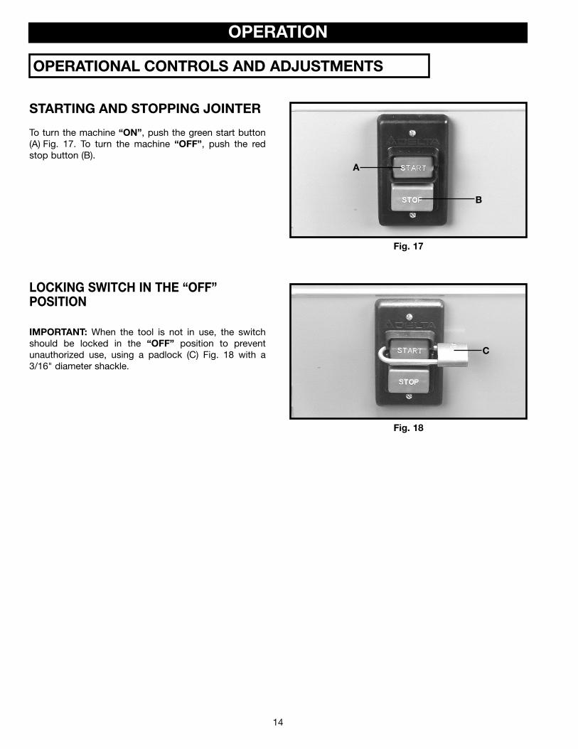
STARTING AND STOPPING JOINTER
To turn the machine “ON”, push the green start button(A) Fig. 17. To turn the machine “OFF”, push the redstop button (B).
LOCKING SWITCH IN THE “OFF”POSITION
IMPORTANT: When the tool is not in use, the switchshould be locked in the “OFF” position to preventunauthorized use, using a padlock (C) Fig. 18 with a3/16" diameter shackle.
Fig. 17
Fig. 18
A
B
C
OPERATIONAL CONTROLS AND ADJUSTMENTS

15
Fig. 19
INFEED TABLEADJUSTMENTS
To raise or lower the infeed table (see Fig. 4A), loosentable lock handle (A) Fig. 19, and move the table raisingand lowering hand lever (B) up or down until the table isat the desired position and tighten table lock handle (A).NOTE: The table lock handle (A) can be repositioned bypulling out the handle and repositioning it on theserrated nut located underneath the handle.
The depth of cut of the infeed table (position of table inrelationship with the cutting circle) can be read with thepointer and scale (G) Fig. 19.
INFEED TABLEPOSITIVE STOPS
D I S C O N N E C T M A C H I N E F R O MPOWER SOURCE.
Positive stops are provided to limit the height of theinfeed table. The positive stops can be set by looseninglock nuts (C) and (D) Fig. 20, and turning the twoadjusting screws (E) and (F). We recommend that theheight of the infeed table be adjusted so that the table,at its highest point, will be 1/2mm (.020" ) below thehighest point of the knives. This is an important featureof your jointer which enables you to rapidly position theinfeed table for a finish or final cut. Fig. 20
OUTFEED TABLEADJUSTMENTS
D I S C O N N E C T M A C H I N E F R O MPOWER SOURCE.
The outfeed table must be exactly level with the kniveswhen the knives are at their highest point of revolution.To move the outfeed table, loosen table lock handle (A)Fig. 21, and move the table raising and lowering handlever (B) up or down until the table is level with theknives. It may be necessary to loosen the two locknuts(C) and (D) Fig. 22, and the two adjusting screws (E) and(F) when moving the table up or down. When the outfeedtable is exactly level with the knives at their highest pointof revolution, tighten table lock handle (A) Fig. 21, andturn adjusting screw (E) Fig. 22, until it bottoms. Thentighten lock nut (C). Screw (F) is also a positive stop forthe lower limit of the outfeed table. We suggest that thisstop also be tightened with locknut (D), when theoutfeed table is set level with the knives. This willprevent the outfeed table from accidentally beinglowered.
Fig. 21
Fig. 22
B
A
G
FD
C E
AB
F
DE C

16
KNIFE ADJUSTMENTSIn order to do accurate work, the knives must be exactlylevel with the outfeed table. To check and adjust,proceed as follows:
D I S C O N N E C T M A C H I N E F R O MPOWER SOURCE.
1. Loosen infeed table lock lever and lower infeed tableas described under section “INFEED TABLEADJUSTMENTS”.
2. Remove cutterhead guard (C) Fig. 23.
3. Place a steel straight edge on the outfeed table,extending over the cutterhead as shown in Fig. 24.
4. Carefully rotate the cutterhead by hand. The knivesshould just touch the straight edge.
5. If the knife is high or low at either end, slightly turnthe four screws (D) Fig. 25, in the knife locking barclockwise to loosen using the wrench (E) supplied.Then adjust the height of the knife by turning theknife raising screws (F) Fig. 26, counterclockwise tolower and clockwise to raise the knife.
C A R E M U S T B E TA K E N W H E NHANDLING THE KNIVES, AS THE CUTTING EDGESARE VERY SHARP. WEAR PROTECTIVE GLOVESWHEN HANDLING THE KNIVES.
If the knife is to be lowered it will be necessary to carefullypush down on the knife with a scrap piece of wood, afterscrews (F) have been turned counterclockwise to achievedesired depth. Tighten four screws (D) Fig. 25, by turningthem counterclockwise, after adjustment is made.
6. Repeat these procedures for adjusting the remainingtwo knives if necessary, and replace cutterheadguard removed in STEP 2.
7. If the knives are set too low, the result will be asshown in Fig. 27, and the finished surface will becurved.
8. If the knives are set too high, the work will begouged, curved, or bowed at the end of the cut, asshown in Fig. 28.
9. As a final check, run a piece of work slowly over theknives for 6 to 8 inches. The wood should rest firmlyon both tables as shown in Fig. 29, with no openspaces under the finished cut.
Fig. 23
Fig. 24
Fig. 25
Fig. 26
D
E
F
F
Fig. 27
Fig. 28 Fig. 29
C

17
FENCE OPERATIONThe fence can be moved across the table by looseninglock lever (A) Fig. 30, move the fence to the desiredposition, and tighten lock lever (A) securely. As the fenceis moved across the table, the sliding portion of thefence bracket (F) guards the cutterhead in back of thefence as shown.
Fig. 30
To tilt the fence to the right or left, loosen handle (B)Fig. 31, pull out plunger (C) and using the fence tiltinglever (D), move the fence to the desired angle andtighten handle (B) securely. NOTE: The handle (B) Fig.31, is spring-loaded and can be repositioned by pullingout the handle and repositioning it on the serrated nutlocated underneath the handle. IMPORTANT: Whencutting a bevel, we suggest that whenever possible thefence be tilted toward the table, as shown in Fig. 32. Thefence will then form a V-shape with the tables, and thework is easily pressed into the pocket while passing itacross the knives.
Fig. 31
Fig. 32
ADJUSTING FENCEPOSITIVE STOPS
The fence on your jointer is equipped with positive stopsat the most used fence positions of 90 degrees and 45degrees right and left. To check and adjust the positivestops, proceed as follows:
D I S C O N N E C T M A C H I N E F R O MPOWER SOURCE.
1. Position the fence 90 degrees to the table by makingsure end of plunger (A) Fig. 33, is engaged in notchin index collar (B), as shown, and tighten lockhandle(C). Fig. 33
A
F
BC
D
A
C
EB

18
Fig. 34
2. Using a square (D) Fig. 34, check to see if the fenceis at 90 degrees to the table, as shown.
3. If the fence is not at 90 degrees to the table, loosenset screw (E) in the index collar (B), Fig. 33, andloosen the fence locking handle (C). Move the fenceuntil you are certain it is at 90 degrees to the tableand tighten locking handle (C) and set screw (E).
Fig. 35
4. Tilt the fence inward as far as possible and using acombination square (F) Fig. 35, check to see if thefence is tilted inward 45 degrees, as shown. If anadjustment is necessary, loosen locknut (H) Fig. 36,and turn adjusting screw (J) in or out until the fenceis 45 degrees to the table, and tighten locknut (H).Then tighten lock handle (C).
5. Tilt the fence outward as far as possible and using acombination square (K) Fig. 37, check to see if thefence is tilted outward 45 degrees, as shown. If anadjustment is necessary, loosen lock handle (C) Fig.37. Loosen locknut (L) and turn adjusting screw (M)until the fence is at 45 degrees to the table. Thentighten locknut (L) and lock handle (C).
Fig. 36
Fig. 37
D
F
K
M
L
C
JH C

19
The following directions will give the beginner a start on jointer operations. Use scrap pieces of lumber to checksettings and to get the feel of the operations before attempting regular work.
THE KNIVES ON THE JOINTER WILL NOT WEAR EVENLY BY FEEDING THE WOOD THROUGH THESAME SPOT ON THE TABLE EVERY TIME. FEED THE WOOD THROUGH THE JOINTER AT DIFFERENT SPOTSON THE TABLE WHEN POSSIBLE, TO HELP ELIMINATE UNEVEN WEAR OF THE KNIVES.
ALWAYS USE CUTTERHEAD GUARD AND KEEP HANDS AWAY FROM CUTTERHEAD. ALWAYSUSE PUSH BLOCKS WHENEVER POSSIBLE. NEVER MAKE JOINTING AND PLANING CUTS
DEEPER THAN 1/8" IN ONE PASS.
Fig. 38
CUTTERHEAD ROTATIONThe rotation of the cutterhead must be in a clockwise direction when viewed from the left side of the
machine; that is, the knives must be rotating toward the infeed table from the top. If the cutterhead rotation is incorrect,disconnect the machine from the power source and proceed as follows:
Single Phase Machines – Interchange leads T5 and T8 in the motor junction box.
Three Phase Machines – Interchange any two of the three incoming power lines.
PLACEMENT OF HANDS DURING FEEDINGAt the start of the cut, the left hand holds the work firmlyagainst the infeed table and fence, while the right handpushes the work toward the knives. After the cut is un-derway, the new surface rests firmly on the outfeed tableas shown in Fig. 38. The left hand should then be movedto the work on the outfeed table, at the same timemaintaining flat contact with the fence. The right handpresses the work forward, and before the right handreaches the cutterhead, it should be moved to the workon the outfeed table.
NEVER PASS HANDS DIRECTLY OVERTHE CUTTERHEAD.
MACHINE USE

20
JOINTING AN EDGEThis is the most common operation for the jointer, thesecuts are made to square an edge of a workpiece. Set theguide fence square with the table. Depth of cut should bethe minimum required to obtain a straight edge. Hold thebest face of the piece firmly against the fence throughoutthe feed as shown in Fig. 39.
MAXIMUM DEPTH OF CUT SHOULDNOT BE MORE THAN 1/8" IN ONE PASS.
DO NOT PERFORM JOINTINGOPERATIONS ON MATERIAL SHORTER
THAN 10 INCHES, NARROWER THAN 3/4 INCH, ORLESS THAN 1/2 INCH THICK (REFER TO FIG. 40).
Fig. 39
Fig. 40
SURFACINGSurfacing is identical to the jointing operation except forthe position of the workpiece. For surfacing, the major flatsurface of the workpiece is placed on the infeed table ofthe jointer with the narrow edge of the workpiece againstthe fence, a shown in Fig. 41. The workpiece ismoved from the infeed table, across the cutterhead to theoutfeed table establishing a flat surface on the workpiece
ALWAYS USE PUSH BLOCKS WHENPERFORMING SURFACING OPERATIONS AND NEVERPASS YOUR HANDS DIRECTLY OVER THECUTTERHEAD.
MAXIMUM DEPTH OF CUT SHOULDNOT BE MORE THAN 1/8" IN ONE PASS.
Fig. 41
To cut a bevel, lock the fence at the required angle andrun the work across the knives while keeping the workfirmly against the fence and tables. Several passes maybe necessary to arrive at the desired result. When theangle is small, there is little difference whether the fenceis tilted to the right or left. However, at greater anglesapproaching 45 degrees, it is increasingly difficult tohold the work properly when the fence is tilted to theright. The advantage of the double-tilting fence isappreciated under such conditions. When tilted to theleft, the fence forms a V-shape with the tables, as shownin Fig. 42, and the work is easily pressed into the pocketwhile passing it across the knives. If the bevel is laid outon the piece in such direction that this involves cuttingagainst the grain, it will be better to tilt the fence to theright.
BEVELING
Fig. 42

21
TAPER CUTSOne of the most useful jointer operations is cutting an edge to a taper. This method can be used on a wide variety ofwork. Tapered legs of furniture are a common example. Instead of laying the piece on the infeed table, lower theforward end of the work onto the outfeed table. Do this very carefully, as the piece will span the knives, and they willtake a “bite” from the work with a tendency to kick back unless the piece is firmly held. Now push the work forwardas in ordinary jointing. The effect is to surface off all the stock in front of the knives, to increasing depth, leaving atapered surface. The ridge left by the knives when starting the taper may be removed by taking a very light cutaccording to the regular method for jointing, with the infeed table raised to its usual position. Practice is required in thisoperation, and the beginner is advised to make trial cuts on waste material. Taper cuts over part of the length and anumber of other special operations can easily be done by the experienced craftsman.
CUTTING A RABBETWhen making a rabbet cut, as shown in Fig. 43, the cutter-head guard must be removed.
AFTER THE RABBET CUT IS COMPLETED,BE CERTAIN GUARD IS REPLACED.1. Adjust the fence so that the distance between theend of the knives and the fence is equal to the width ofthe rabbet.2. Lower the infeed table an amount equal to the depthof the rabbet. If the rabbet is quite deep, it may benecessary to cut it in two or more passes. In that event,the table is lowered an amount equal to about half thedepth of the rabbet for the first pass, then lowered againto proper depth to complete the cut.
Fig. 43
SURFACING WARPED PIECESIf the wood to be surfaced is dished or warped, takelight cuts until the surface is flat. Avoid forcing suchmaterial down against the table; excessive pressure willspring it while passing the knives, and it will spring backand remain curved after the cut is completed.
SURFACING SHORT OR THIN WORK
WHEN SURFACING SHORT OR THINPIECES, ALWAYS USE PUSH BLOCKS TO MINIMIZEALL DANGER TO THE HANDS. Fig. 44, illustrates usingthe Delta Push Blocks properly.
DO NOT PERFORM SURFACINGOPERATIONS ON MATERIAL SHORTER THAN 10INCHES, NARROWER THAN 3/4 INCH, WIDER THAN8 INCHES, OR LESS THAN 1/2 INCH THICK (REFERTO FIG. 45).
Fig. 44
Fig. 45
MINIMUM AND MAXIMUM SURFACINGDIMENSIONS
8"

22
DIRECTION OF GRAINAvoid feeding work into the jointer against the grain asshown in Fig. 46. The result will be chipped andsplintered edges. Feed with the grain as shown in Fig.47, to obtain a smooth surface.
Fig. 46
Fig. 47
After considerable use, the knives will become dull and it will not be possible to do accurate work. Unless badlydamaged by running into metal or other hard material, the knives may be sharpened as follows:
WHETTING KNIVESDISCONNECT MACHINE FROM POWERSOURCE.
Use a fine carborundum stone, cover it partly with paperas indicated in Fig. 48 to avoid marking the table. Laythe stone on the infeed table, lower the table and turnthe cutterhead forward until the stone lies flat on thebevel of the knife as shown. Hold the cutterhead fromturning, and whet the beveled edge of the knife, strokinglengthwise by sliding the stone back and forth acrossthe table. Do the same amount of whetting on each ofthe three knives.
Fig. 48
MAINTENANCE
TROUBLESHOOTINGFor assistance with your tool, visit our website at www.deltamachinery.com for a list of service centers or call theDELTA Machniery help line at 1-800-223-7278 (In Canada call 1-800-463-3582).
KEEP MACHINE CLEANPeriodically blow out all air passages with dry compressedair. All plastic parts should be cleaned with a soft dampcloth. NEVER use solvents to clean plastic parts. They couldpossibly dissolve or otherwise damage the material.
Wear ANSI Z87.1 safety glasses whileusing compressed air.
FAILURE TO STARTShould your machine fail to start, check to make sure theprongs on the cord plug are making good contact in theoutlet. Also, check for blown fuses or open circuit breakersin the line.
LUBRICATIONApply household floor paste wax to the machine table andextension table or other work surface weekly.
PROTECTING CAST IRON FROM RUSTTo clean and protect cast iron tables from rust, you willneed the following materials: 1 pushblock from a jointer,1 sheet of medium Scotch-Brite™ Blending Hand Pad, 1can of WD-40®, 1 can of degreaser, 1 can of TopCote®
Aerosol. Apply the WD-40 and polish the table surfacewith the Scotch-Brite pad using the pushblock as aholddown. Degrease the table, then apply the TopCote®
accordingly.

23
REMOVING, REPLACING, ANDRESETTING KNIVESIf the knives are removed from the cutterhead for re-placement or sharpening, care must be used inremoving, replacing, and resetting them.
D I S C O N N E C T M A C H I N E F R O MPOWER SOURCE.
1. Move the fence to the rear and remove thecutterhead guard.
BE EXTREMELY CAREFUL THATYOUR HANDS DO NOT COME IN
CONTACT WITH THE KNIVES. THE KNIVES AREVERY SHARP. WEAR PROTECTIVE GLOVES WHENHANDLING THE KNIVES.2. Using wrench (A) Fig. 49, slightly loosen the four
locking screws (B) in each knife slot by turning thescrews (B) clockwise. Loosen screws (B) Fig. 49,further and remove knife and knife locking bar.
3. Fig. 50, shows the knife (C) and knife locking bar (D)removed from the cutterhead. Remove theremaining two knives and locking bars, in the samemanner.
4. Using wrench (E) Fig. 50, lower the two knifeadjustment blocks to the bottom of the cutterhead byturning screws (F) counterclockwise in all three slotsof the cutterhead.
5. Before assembling knives make certain the knivesand locking bars are thoroughly clean and free ofgum and pitch.
6. Place the knife locking bars (D) Fig. 50, and knives (C)into each slot in the cutterhead.
C A R E M U S T B E TA K E N W H E NINSERTING THE KNIVES AS THE
CUTTING EDGES ARE VERY SHARP. WEARPROTECTIVE GLOVES WHEN HANDLING THEKNIVES.7. Push the knife down as far as possible and turn each
screw (B) Fig. 49, counterclockwise just enough tohold the knife in position. Replace the remaining twoknifes in the same manner.
K N I V E S M U S T B E I N S TA L L E DCORRECTLY AS SHOWN IN FIG. 51.
8. The knives are adjusted correctly when the cuttingedge of the knife extends out .015” from thecutterhead diameter.
9. Carefully rotate the cutterhead (G) Fig. 52, until theround portion of the cutterhead is on top as shown.
10. Place a .015” feeler gage (H) Fig. 52, on thecutterhead and using a straight edge (J) on the reartable adjust the height of the rear table until it is.015” above the cuttinghead diameter, as shown.
11. Lock the rear table in position and remove the feelergage.
Fig. 49
Fig. 50
Fig. 51
Fig. 52
B A
C
DE
F
F
J
H
G

24
12. Lower the infeed table and place a straight edge (J)Fig. 53, on the outfeed table extending over thecutterhead as shown.
13. Rotate the cutterhead by hand until the knife is at itshighest point at each end of the cutterhead. To raisethe knife, use wrench (E) Fig. 53, and turn raisingscrew clockwise until the knife just touches thestraight edge (J) on each end and center of thecutterhead when the knife is at its highest point.When you are certain the knife is adjusted properly,tighten the four locking screws (B) Fig. 49, by turningthem counterclockwise.
14. Adjust the remaining two knives in the same manner.MAKE CERTAIN THAT ALL KNIVES ARESECURELY FASTENED IN CUTTERHEADBEFORE TURNING ON POWER.
15. Replace cutterhead guard.
Fig. 53
J
E

25
PU
SH
STI
CK
MA
KE
FRO
M 1
/2"
OR
3/4"
WO
OD
OR
THIC
KN
ES
SLE
SS
THA
NW
IDTH
OF
MAT
’L.
TOB
EC
UT
CU
TO
FFH
ER
ETO
PU
SH
1/4
" W
OO
D
CU
TO
FFH
ER
ETO
PU
SH
1/2
" W
OO
D
NO
TCH
TOH
ELP
PR
EV
EN
TH
AN
DFR
OM
SLI
PP
ING
1/2"
SQ
UA
RE
S
CONSTRUCTING A PUSH STICKNarrow pieces of stock that are close to 10 inch minimum length should be handled with a push stick
and push block. The diagram below is a pattern for a push stick.

26
NOTES

27
PARTS, SERVICE OR WARRANTY ASSISTANCEAll Delta Machines and accessories are manufactured to high quality standards and are serviced by a networkof Porter-Cable • Delta Factory Service Centers and Delta Authorized Service Stations. To obtain additionalinformation regarding your Delta quality product or to obtain parts, service, warranty assistance, or the locationof the nearest service outlet, please call 1-800-223-7278 (In Canada call 1-800-463-3582).
A complete line of accessories is available from your Delta Supplier, Porter-Cable • Delta Factory Service Centers,and Delta Authorized Service Stations. Please visit our Web Site www.deltamachinery.com for a catalog orfor the name of your nearest supplier.
Since accessories other than those offered by Delta have not been tested with this product, use of such accessories could be hazardous. For safest operation, only Delta recommended accessories should be used with this product.
ACCESSORIES
Two Year Limited New Product WarrantyDelta will repair or replace, at its expense and at its option, any new Delta machine, machine part, or machine accessorywhich in normal use has proven to be defective in workmanship or material, provided that the customer returns the productprepaid to a Delta factory service center or authorized service station with proof of purchase of the product within twoyears and provides Delta with reasonable opportunity to verify the alleged defect by inspection. For all refurbished Deltaproduct, the warranty period is 180 days. Delta may require that electric motors be returned prepaid to a motormanufacturer’s authorized station for inspection and repair or replacement. Delta will not be responsible for any asserteddefect which has resulted from normal wear, misuse, abuse or repair or alteration made or specifically authorized byanyone other than an authorized Delta service facility or representative. Under no circumstances will Delta be liable forincidental or consequential damages resulting from defective products. This warranty is Delta’s sole warranty and setsforth the customer’s exclusive remedy, with respect to defective products; all other warranties, express or implied, whetherof merchantability, fitness for purpose, or otherwise, are expressly disclaimed by Delta.
SERVICE
WARRANTY

The following are trademarks of PORTER-CABLE • DELTA (Las siguientes son marcas registradas de PORTER-CABLE • DELTA S.A.) (Les marquessuivantes sont des marques de fabriquant de la PORTER-CABLE • DELTA): Auto-Set®, BAMMER®, B.O.S.S.®, Builder’s Saw®, Contractor’s Saw®,Contractor’s Saw II™, Delta®, DELTACRAFT®, DELTAGRAM™, Delta Series 2000™, DURATRONIC™, Emc²™, FLEX®, Flying Chips™, FRAME SAW®,Grip Vac™, Homecraft®, INNOVATION THAT WORKS®, Jet-Lock®, JETSTREAM®, ‘kickstand®, LASERLOC®, MICRO-SET®, Micro-Set®, MIDI LATHE®,MORTEN™, NETWORK™, OMNIJIG®, POCKET CUTTER®, PORTA-BAND®, PORTA-PLANE®, PORTER-CABLE®&(design), PORTER-CABLE®PROFESSIONAL POWER TOOLS, PORTER-CABLE REDEFINING PERFORMANCE™, Posi-Matic®, Q-3®&(design), QUICKSAND®&(design),QUICKSET™, QUICKSET II®, QUICKSET PLUS™, RIPTIDE™&(design), SAFE GUARD II®, SAFE-LOC®, Sanding Center®, SANDTRAP®&(design), SAWBOSS®, Sawbuck™, Sidekick®, SPEED-BLOC®, SPEEDMATIC®, SPEEDTRONIC®, STAIR EASE®, The American Woodshop®&(design), The LumberCompany®&(design), THE PROFESSIONAL EDGE®, THE PROFESSIONAL SELECT®, THIN-LINE™, TIGER®, TIGER CUB®, TIGER SAW®,TORQBUSTER®, TORQ-BUSTER®, TRU-MATCH™, TWIN-LITE®, UNIGUARD®, Unifence®, UNIFEEDER™, Unihead®, Uniplane™, Unirip®, Unisaw®,Univise®, Versa-Feeder®, VERSA-PLANE® , WHISPER SERIES®, WOODWORKER’S CHOICE™. Trademarks noted with ™ and ® are registered in the United States Patent and Trademark Office and may also be registered in other countries. LasMarcas Registradas con el signo de ™ y ® son registradas por la Oficina de Registros y Patentes de los Estados Unidos y también pueden estarregistradas en otros países.
PORTER-CABLE • DELTA SERVICE CENTERS(CENTROS DE SERVICIO DE PORTER-CABLE • DELTA)
Parts and Repair Service for Porter-Cable • Delta Machinery are Available at These Locations(Obtenga Refaccion de Partes o Servicio para su Herramienta en los Siguientes Centros de Porter-Cable • Delta)
Authorized Service Stations are located in many large cities. Telephone 800-438-2486 or 731-541-6042 for assistance locating one.Parts and accessories for Porter-Cable·Delta products should be obtained by contacting any Porter-Cable·Delta Distributor, AuthorizedService Center, or Porter-Cable·Delta Factory Service Center. If you do not have access to any of these, call 800-223-7278 and you willbe directed to the nearest Porter-Cable·Delta Factory Service Center. Las Estaciones de Servicio Autorizadas están ubicadas en muchasgrandes ciudades. Llame al 800-438-2486 ó al 731-541-6042 para obtener asistencia a fin de localizar una. Las piezas y los accesoriospara los productos Porter-Cable·Delta deben obtenerse poniéndose en contacto con cualquier distribuidor Porter-Cable·Delta, Centrode Servicio Autorizado o Centro de Servicio de Fábrica Porter-Cable·Delta. Si no tiene acceso a ninguna de estas opciones, llame al800-223-7278 y le dirigirán al Centro de Servicio de Fábrica Porter-Cable·Delta más cercano.
ARIZONATempe 85282 (Phoenix)2400 West Southern AvenueSuite 105Phone: (602) 437-1200Fax: (602) 437-2200
CALIFORNIAOntario 91761 (Los Angeles)3949A East Guasti RoadPhone: (909) 390-5555Fax: (909) 390-5554
San Diego 921117638 Clairemnot Blvd.Phone: (858) 277-9595Fax: (858) 277-9696
San Leandro 94577 (Oakland)3039 Teagarden StreetPhone: (510) 357-9762Fax: (510) 357-7939
COLORADOArvada 80003 (Denver)8175 Sheridan Blvd., Unit SPhone: (303) 487-1809Fax: (303) 487-1868
FLORIDADavie 33314 (Miami)4343 South State Rd. 7 (441)Unit #107Phone: (954) 321-6635Fax: (954) 321-6638
Tampa 33609 4538 W. Kennedy BoulevardPhone: (813) 877-9585Fax: (813) 289-7948
GEORGIAForest Park 30297 (Atlanta)5442 Frontage Road,Suite 112Phone: (404) 608-0006Fax: (404) 608-1123
ILLINOISAddison 60101 (Chicago)400 South Rohlwing Rd.Phone: (630) 424-8805Fax: (630) 424-8895
Woodridge 60517 (Chicago)2033 West 75th StreetPhone: (630) 910-9200Fax: (630) 910-0360
MARYLANDElkridge 21075 (Baltimore)7397-102 Washington Blvd.Phone: (410) 799-9394Fax: (410) 799-9398
MASSACHUSETTSFranklin 02038 (Boston)Franklin Industrial Park101E Constitution Blvd.Phone: (508) 520-8802Fax: (508) 528-8089
MICHIGANMadison Heights 48071 (Detroit)30475 Stephenson HighwayPhone: (248) 597-5000Fax: (248) 597-5004MINNESOTAMinneapolis 554295522 Lakeland Avenue NorthPhone: (763) 561-9080Fax: (763) 561-0653
MISSOURINorth Kansas City 641161141 Swift AvenuePhone: (816) 221-2070Fax: (816) 221-2897
St. Louis 631197574 Watson RoadPhone: (314) 968-8950Fax: (314) 968-2790
NEW YORKFlushing 11365-1595 (N.Y.C.)175-25 Horace Harding Expwy.Phone: (718) 225-2040Fax: (718) 423-9619
NORTH CAROLINACharlotte 282709129 Monroe Road, Suite 115Phone: (704) 841-1176Fax: (704) 708-4625
OHIOColumbus 432144560 Indianola AvenuePhone: (614) 263-0929Fax: (614) 263-1238
Cleveland 441258001 Sweet Valley DriveUnit #19Phone: (216) 447-9030Fax: (216) 447-3097
OREGONPortland 972304916 NE 122 nd Ave.Phone: (503) 252-0107Fax: (503) 252-2123
PENNSYLVANIAWillow Grove 19090(Philadelphia)520 North York RoadPhone: (215) 658-1430Fax: (215) 658-1433
TEXASCarrollton 75006 (Dallas)1300 Interstate 35 N, Suite 112Phone: (972) 446-2996Fax: (972) 446-8157
Houston 770434321 Sam Houston Parkway,WestSuite 180Phone: (713) 983-9910Fax: (713) 983-6645
WASHINGTONAuburn 98001(Seattle)3320 West Valley HWY, NorthBuilding D, Suite 111Phone: (253) 333-8353Fax: (253) 333-9613
PC-0704-149
CANADIAN PORTER-CABLE • DELTA SERVICE CENTERSALBERTABay 6, 2520-23rd St. N.E.Calgary, AlbertaT2E 8L2Phone: (403) 735-6166Fax: (403) 735-6144
BRITISH COLUMBIA8520 Baxter PlaceBurnaby, B.C.V5A 4T8Phone: (604) 420-0102Fax: (604) 420-3522
MANITOBA1699 Dublin AvenueWinnipeg, ManitobaR3H 0H2Phone: (204) 633-9259Fax: (204) 632-1976
ONTARIO505 Southgate DriveGuelph, OntarioN1H 6M7Phone: (519) 767-4132Fax: (519) 767-4131
QUÉBEC1515 ave.St-Jean Baptiste, Suite 160Québec, QuébecG2E 5E2Phone: (418) 877-7112Fax: (418) 877-7123
1447, BeginSt-Laurent, (Montréal),QuébecH4R 1V8Phone: (514) 336-8772Fax: (514) 336-3505