Mechanical Modeling - Exclusive Mechancial CAD Services, Reverse Engineering
Upload
duongkhuongCategory
view
236download
0
University of Pittsburgh Index Mechanical Design Standards 1 April 7, 2017
DIVISION J MECHANCIAL DESIGN STANDARDS
INDEX J.1 210100 FIRE PROTECTION SYSTEMS…………………………...........210100-1 through 7 J.2 220100 PLUMBING………………………………………………..............220100-1 through 14 J.3 230100 MECHANCIAL GENERAL REQUIREMENTS……………........230100-1 through 8 J.4 230500 BASIC MEATERIALS AND METHODS……..……………….....230500-1 through 3 J.5 230513 MOTORS……………………………………….…………………..230513-1 J.6 230523 GENERAL DUTY VALVES………..…………..………….……...230523-1 through 6 J.7 230553 IDENTIFICATION OF MECHANICAL SYSTEMS..……………230553-1 through 7 J.8 230700 INSULATION……………………….…………..………………….230700-1 through 5 J.9 232113 MECHANICAL PIPING SYSTEMS…………..………………….232113-1 through 12 J.10 232115 PIPING ACCESSORIES………………………..………………..232115-1 through 5 J.11 233100 DUCT AND AIRSIDE ACCESSORIES……...………………….233100-1 through 7 J.12 238000 MECHANICAL EQUIPMENT……..…………..………………….238000-1 through 13 J.13 239000 HVAC INSTRUMENTATION AND CONTROLS...…………….238000-1 through 16

University of Pittsburgh Fire Protection Systems Mechanical Design Standards Section 210100 - 1 April 19, 2017
UNIVERSITY OF PITTSBURGH FIRE PROTECTION SYSTEMS DESIGN STANDARDS SECTION 210100 – FIRE PROTECTION SYSTEMS
1. The design requirements contained in this tab (Division 21) shall be employed for every project. Approval must be obtained from the University of Pittsburgh Mechanical Engineer assigned to the project for any deviations made from the design requirements contained in this division. The design requirements herein shall be used as the minimum requirements.
2. Codes and Standards: The Design Professional shall comply with the requirements of all applicable codes and standards for each specific design project. The latest enforceable editions at the time of the Schematic Design submittal shall govern edition of standards to be used.
a. National Fire Protection Association (NFPA) Standards (latest edition referenced by current codes)
b. Underwriters Laboratories Inc (UL) c. International Fire Code (latest edition) d. International Building Code (latest edition) e. International Mechanical Code 2015 f. International Plumbing Code 2015 g. International Fuel Gas Code (latest edition) h. Pittsburgh Water and Sewer Authority, for Oakland Campus only i. National Electrical Code (latest edition) j. American Society of Mechanical Engineers k. American Institute of Architects (AIA) l. American National Standard Institute (ANSI) m. American Society of Testing and Materials (ASTM) n. University of Pittsburgh Environmental Health and Safety Department. o. Other as determined by Authority Having Jurisdiction
3. All new and renovated facilities shall be fully sprinkled regardless of code requirements.
a. Special situations shall be handled on a case by case situation.
4. All appropriate NFPA 12, 20 and 25 Test Certificate’s and documentation shall be provided to the University as part of the project Closeout documentation.
5. All designs for new and renovations with less than 50 sprinkler heads shall be based on the last available hydrant water flow test. For systems with 50 or more sprinkler heads, the design Professional shall request a hydrant flow test from the appropriate authority.
a. As part of the Schematic Design Process a hydrant flow test will be performed and this information shall be listed on the fire protection drawings.
b. For projects with less than 50 sprinkler heads (relocated and/or new) the final hydraulic calculations shall be based on a new hydrant water flow test as well as the latest fire pump test results, where applicable.
6. Calculations:
a. Hydraulic calculation and piping drawings shall be prepared under the supervision of a qualified fire protection engineer or designer having a NICET level III certification in Automatic Sprinkler Systems Layout. After construction has been completed the installation contractor shall provide a set of record drawings (as-builts).
b. Design densities and demand areas shall be determined per NFPA and IFC.

University of Pittsburgh Fire Protection Systems Mechanical Design Standards Section 210100 - 2 April 19, 2017
c. All hazard groups shall be approved by the University Mechanical Engineer assigned to the project AND by University EH&S.
d. Rooms dedicated for main electrical switchgear and generators may have their sprinkler protection omitted provided they have direct access to the exterior and are enclosed by 2-hour rated construction in addition to requirements by NFPA and AHJ.
e. All fire protection systems shall be monitored via the building’s Fire Alarm System.
f. Design Calculations for inside pipe are to include C = 100 for dry pipe and pre-action systems and C = 120 for wet and deluge systems.
g. A 10psi safety factor shall be designed into all hydraulic designed systems. h. Buildings shall be zoned by floor to the greatest extent possible. i. Extended coverage sprinkler heads are not to be used without approval by the
University Mechanical Engineer AND by University EH&S assigned to the project.
j. Provide a utility approved backflow device on all fire water piping entrances to buildings.
k. The Installing Division 21 Contractor shall be present at all system tests and inspections. The Designer shall require this through inclusion in their specification package.
7. University Insurance Company a. FM Global shall review final drawings, specifications and hydraulic calculations.
Any additional comments or suggestions by FM Global shall be reviewed and where appropriate included in the design. This shall be as directed by University Mechanical Engineer assigned to project.
8. Design Drawing Requirements: a. A code summary table shall be provided on the Fire Protection lead drawing
sheet. The summary shall include: i. Project name and physical address ii. Occupancy description and hazard classification iii. Design Summary:
1. System square feet 2. Design Area 3. Ceiling heights 4. Type of system (wet/dry/etc) 5. Criteria for design (NFPA 13/20 etc) 6. AHJ 7. Design Density 8. Hose Stream allowance (GPM) 9. Sprinkler Spacing (Sqft) 10. K-Factor
iv. Water Supply Information 1. Hydrant locations 2. Date/Time of test 3. Static Pressure 4. Residual Pressure 5. Flow Rate 6. Presence of a Fire Pump, Flow, Pressure, HP
b. All drawings shall show fire and/or smoke rated walls, floors and other
assemblies. Areas not sprinkled and areas subject to freezing shall be noted. c. The Professional shall identify the different classifications of occupancies on
each floor or area along with water density requirements by zone.

University of Pittsburgh Fire Protection Systems Mechanical Design Standards Section 210100 - 3 April 19, 2017
d. The drawings shall identify new and existing riser locations, sizes of risers, locations of main branches and sizes.
e. The drawings shall show locations of all new sprinkler heads, valves, test connections, fire department connections, tamper switches as well as any other items or devices that require connection to the fire alarm system.
f. The design professional shall perform a cross disciplinary check with the other professionals to ensure proper clearance between utilities, systems and components.
g. All existing to remain as well as new tamper and flow switches within the boundary of the project shall be connected to the building’s addressable fire alarm system.
9. Piping and Valves: a. The fire service and the domestic service shall be brought into the building as
separate feeds from the water main in the street as per the International Plumbing Code. Sizing of mains shall be determined by professional.
b. Copper piping for sprinkler systems shall not be allowed on any University of Pittsburgh property.
i. Unless required for areas, i.e. MRI suites. c. CPVC shall be used only if approved in writing by University Mechanical
Engineer assigned to the project. d. Dry Pipe and Pre-Action system piping shall be required to be schedule 40
carbon steel piping or Schedule 10 Stainless Steel. e. Wet Pipe system piping shall be schedule 40 carbon steel piping. f. Grooved couplings only as manufactured by Victaulic shall be allowed for use as
sprinkler piping. Couplings shall be Victaulic FireLock. A visual inspection shall be provided for in the design to ensure all couplings are properly installed. Gaskets shall be listed for their intended use and specified in the project documents. Installing contractors must have had factory/on-site training within the past 12 months prior to starting any installation.
g. Provide an approved double detector check valve back flow preventer with a by-pass meter for every sprinkler protected building and system. This assembly shall be located within the building where it is accessible for testing and maintenance. Meter shall be provided by Utility. Obtain approval for location of meter and remote reading device from Utility. Provide shutoff valve on building side of meter. Drain off backflow device shall be routed to nearest drain or daylight to exterior. Coordinate any exterior drain with University.
h. All alarming and supervisory devices shall be monitored by the building’s Fire Alarm System.
i. All fire protection test drains shall terminate at a floor drain or to the outside at an appropriate location approved by the University Architect and University Mechanical Engineer. Test drain discharge shall not be made through windows.
j. Standpipes shall be installed per requirements of IFC/IBC and NFPA 14 as well as required by local AHJ (Authority Having Jurisdiction).
i. The Professional shall provide appropriate drainage with each standpipe for testing of the fire hose valves with capped connections, confirm size with City of Pittsburgh Bureau of Fire, or local AHJ.
k. Ensure high point vents and a drain line with quarter turn ball valve are provided on every floor/zone to allow testing, filling and draining of system. Drain shall be routed to daylight, location to be approved by University. Drain shall be routed to janitor’s sink or mechanical room floor drain.
l. All fire piping shall be painted red or labeled as fire protection. Labelling shall be visible from any vantage point where sprinkler pipe is visible.
m. The standpipes and associated accessories in buildings with fire pumps shall be designed for a minimum of 300 psig operating pressure.

University of Pittsburgh Fire Protection Systems Mechanical Design Standards Section 210100 - 4 April 19, 2017
n. The fire hose valves shall be set for 100 psig operating pressure or pressure required by AHJ, whichever is greater.
o. Inspector’s test connections on dry pipe systems shall be installed in a location that is fully accessible and meets all NFPA and Code requirements.
p. The Professional shall be responsible for identifying areas where the sprinkler pipes and sprinkler heads of a wet pipe system could freeze in the absence of ventilation or heat or locations being too close to the exterior wall. Means of freeze protection shall be provided in the design under these circumstances. Freeze protection means shall be provided with an alarm to the campus BAS.
q. Any heat tracing of the wet standpipes such as in garage areas or other areas shall be alarmed for freeze protection of the pipes.
r. The Professional will review the use of fire department connections on the building roof where equipment is being installed. The isolation valve for the roof connection may be located in the stairwell.
s. Provide sprinklers in the elevator shafts as per the International Fire Protection Code and NFPA 13.
t. Provides sprinklers in the elevator machine rooms. The sprinklers in the machine room shall have heat detectors located within 2 feet of each sprinkler head as per NFPA 13 and NFPA 72 requirements. The elevator motors shall be provided with shunt trip breakers. All work in existing facilities shall be coordinated with the Elevator Maintenance Contractor.
u. Valves: i. UL-listed and FM-approved, with 300-psig non-shock minimum working
pressure rating. 1. Valves for use with grooved piping may be grooved type,
compatible with the Victaulic system. v. Limited area sprinklers shall be allowed on a case by case basis.
10. Fire Department Connections
a. Exposed, Wall-Type Fire Department Connections: UL 405, cast-brass body; NH-standard thread inlets according to NFPA 1963 and matching local fire department threads; and threaded NPS outlet. Include lugged cap, gasket, and chain; lugged swivel connection and drop clappers for each hose connection inlet; and round wall escutcheon plate with marking “AUTO SPRINKLER”, “AUTO SPRINKLER STANDPIPE”, OR “STANDPIPE” as applicable.
i. Connections: Two 2-1/2-inch inlets and 4-inch outlet. ii. Direction of Outlet: Back, straight. iii. Finish: Polished chrome plated. iv. Coordinate type of Fire Department Connection required with local
municipality for all regional campuses. v. Where an FDC serves multiple standpipes and/or zones in a facility, the
signage shall also indicate which zones and standpipes are served. b. The City of Pittsburgh Bureau of Fire requires a combination strobe/horn to be
installed above the FDC. This shall be included as part of the Building Fire Alarm system. Coordinate alarm requirements at the Fire Department Connection with local municipality for all regional campuses.
11. Sprinkler Heads
a. Must be UL and/or FM listed. i. With preference to sprinkler heads approved by UL and FM.
b. Rooms without Ceilings: Upright sprinklers. c. Rooms with Suspended Ceilings: Concealed sprinklers. d. Lobby/Reception Area: Concealed sprinklers. e. Wall Mounting: Sidewall sprinklers. f. Loading Docks/Walk-in Coolers/Freezers: Dry pendant sprinklers

University of Pittsburgh Fire Protection Systems Mechanical Design Standards Section 210100 - 5 April 19, 2017
g. Sprinkler Finishes: Use sprinklers with following finishes: i. Upright, Pendent, and Sidewall Sprinklers: Chrome-plated in finished
spaces exposed to view; rough bronze in unfinished spaces not exposed to view; wax-coated where exposed to acids, chemicals, or other corrosive fumes.
ii. Concealed Sprinklers: Rough brass, with factory-painted white cover plate.
iii. Recessed Sprinklers: Bright chrome, with bright chrome escutcheon. h. Flexible arm-overs shall not be allowed inside a building. In areas exposed to
freezing, flexible arm-overs may be allowed, only upon written approval of University Mechanical Engineer assigned to the project.
i. Provide spare sprinkler heads per NFPA 13, or at a minimum of 6 per type installed. Provide spare sprinkler heads in a purpose built cabinet.
j. Provide with two sprinkler wrenches as well as concealed sprinkler cover plates equal to 25% of the number installed.
k. Where sprinkler heads are exposed to possible damage, wire guards shall be installed over heads. Sprinkler head guards shall be listed, supplied, and approved for use with the sprinkler heads by the sprinkler head manufacturer.
12. Fire Pumps: a. Fire pumps shall be centrifugal, horizontal split case single stage pumps with
suction and discharge connections in the lower half of the case. Use of vertical pumps shall be approved by University Mechanical Engineer assigned to the project.
b. Pumps shall not have less than 150 percent of rated capacity at not less than 65 percent of total head with a shutoff limit to 140 percent of total head.
c. Pumps must provide, as a minimum, a residual pressure of 100 psi while flowing 500 gpm at the roof of each served facility.
d. Provide a roof hydrant or a hose connection to allow yearly flow and pressure testing.
i. This is a requirement for high-rise buildings only at regional campuses. ii. This is a requirement for all facilities within the City of Pittsburgh.
1. In this application iii. AHJ shall be contacted to ensure compliance on all facilities. iv. Designer shall ensure proper drainage is available at the roof locations of
hydrants and hose connections. e. Wear rings shall be renewable case bronze locked into position. f. Provide pump with full by-pass with check valve. g. Provide with a shaft grounding ring, installed per manufacturer’s
recommendations. h. The pump shall be connected to the driver with a rigid coupling. i. Provide a combination factory-wired as assembled fire pump controller with
automatic transfer switch conforming to the latest edition of NFPA 20 and NFPA 70.
i. The pump controller shall be arranged for manual stop only. ii. Controller shall be tied into the Building Automation System and
monitored for troubles, alarms and on/off status. j. Provide a main water flow switch downstream of the fire pump discharge, this
shall be an alarm initiating device and the fire pump running shall be monitored as a trouble condition not an alarm condition.
k. Automatic and manual transfer switch shall be electrically operated and mechanically held switch. (Controller shall be soft start.)
l. Provide with automatic and manual shutdown. m. Jockey pump controller shall be across the line type for combined automatic and
manual operation.

University of Pittsburgh Fire Protection Systems Mechanical Design Standards Section 210100 - 6 April 19, 2017
n. All new fire pump rooms shall exit directly to exterior of building. No interior entrances to room shall be allowed.
i. Rooms shall maintain a minimum of a two hour fire rating. ii. No storage is permitted in fire pump rooms. iii. No other utilities or other MEP ductwork, piping etc. are permitted to
pass through the fire pump room unless directly associated with the room per NFPA 20.
o. Where fire pumps are provided, the Professional shall provide adjustable pressure reducing valves on all fire hose connections, floor control valves and any other isolation valves to the sprinkler system.
13. Miscellaneous: a. Air compressors for all dry systems shall be provided with an air dryer and be
placed on emergency power. i. Size compressors for the code required 30 minute refill time limit.
b. Clean Agent fire suppression systems may be considered for use in data centers and other computer server areas. Coordinate with University Mechanical Engineer assigned to project.
c. Kitchen hoods shall be protected by a wet chemical fire suppression system. Coordinate with the Mechanical, Fire Alarm, Plumbing Kitchen and Architectural Design Professionals.
d. The Professional shall indicate all service and maintenance areas. This information should be coordinated with plumbing, electrical, architectural, civil and structural drawings.
14. Personnel Training:
a. Provide at a minimum of 8 hours of training on all aspects of fire protection system for University staff. Training shall not be held until the start-up and commissioning of the subject electrical equipment or system is complete.
15. Demonstration of System Operation (system checkout):
a. Testing i. A final acceptance test of the sprinkler system, standpipes, and fire
pumps conducted by the contractor in the presence of the Professional and University personnel.
ii. The sprinkler system shall be designed to minimize maintenance. iii. All test stations shall be located in areas where testing does not affect
occupants or programs and water discharge will not collect or freeze.
16. System Commissioning a. In renovations where zones are added to/modified, the zone control valves and
all associated tampers and flows shall be tested prior to final project acceptance. b. All new zones and systems shall be functional tested.
17. “AS-BUILT” Drawings and O&M Manuals
a. The Professional shall specify that, during the course of the work, the Contractor shall record all changes in the work on a set of the contract documents (in electronic format) to include one (1) set of corrected specifications. The Professional shall revise the original documents and provide the “As-Built” information in computer file form (PDF and DWG) to the University. This applies to all Trades involved with the work.
b. The date of substantial completion of the construction contract takes effect on the date when both the required training and O&M manuals have been fully received.
c. All major fire protection equipment (including but not limited to fire pump, fire pump controllers, dry-pipe cabinets, clean agent systems etc) shall have a warranty label

University of Pittsburgh Fire Protection Systems Mechanical Design Standards Section 210100 - 7 April 19, 2017
placed in a conspicuous place. Label shall indicate start and end date of the warranty period. The start date shall be the date of final acceptance by the University.
18. Where applicable special considerations: a. Provide alternate fire suppression for areas where required based on use and/or
materials present in certain laboratories or other specialty spaces. All systems shall meet applicable codes and NFPA requirements. Refer to Laboratory Design Manual Section for additional guidelines.
b. Provide pressurization of stairwells, elevators in all high rise buildings, where required, to meet the requirements of IFC/IBC/IMC, NFPA 92A and ASHRAE Guidelines.
c. Provide atrium smoke exhaust systems where required to meet the requirements of IFC/IBC/IMC, NFPA 92A and ASHRAE Guidelines.
END OF SECTION

University of Pittsburgh Plumbing General Requirements Mechanical Design Standards Section 220100 - 1 April 19, 2017
UNIVERSITY OF PITTSBURGH PLUMBING DESIGN STANDARDS SECTION 220100 - PLUMBING GENERAL REQUIREMENTS
1. The design requirements contained in this tab (Division 22) shall be employed for every project. Approval must be obtained from the University of Pittsburgh Mechanical Engineer assigned to the project for any deviations made from the design requirements contained in this division. The design requirements herein shall be used as the bare minimum requirements.
2. Codes and Standards: The Design Professional shall comply with the requirements of all applicable codes and standards for each specific design project.
a. International Building Code (latest edition) b. International Mechanical Code 2015 c. International Plumbing Code 2015 d. International Fire Code (latest edition) e. International Fuel Gas Code (latest edition) f. International Energy Conservation Code g. National Fire Protection Association (NFPA) Standards h. Reduction of Lead in Drinking Water Act i. ASHRAE Standards (latest editions), including but not limited to:
i. 188-2015 j. American Society of Plumbing Engineers (ASPE) k. Allegheny County Plumbing Code (latest edition), for Oakland Campus only l. Pittsburgh Water and Sewer Authority, for Oakland Campus only m. Local Water and Sewer Authorities for Regional Campuses. n. National Electrical Code (latest edition) o. International Building Electrical Code (latest edition) p. American Society of Mechanical Engineers q. American Assoc. for Accreditation of Laboratory Animal Care (AAALAC) r. National Institute of Health (NIH) s. American Institute of Architects (AIA) t. American Conference of Governmental Industrial Hygienists(ACGIH) u. American National Standard Institute (ANSI) v. American Society of Testing and Materials (ASTM)
3. General:
a. When renovating whole floors, or areas where gang toilets are located, vertical waste and vent piping shall be replaced from floor to ceiling.
b. The minimum pipe size for domestic cold water, hot water and recirculated hot water piping shall be 3/4".
c. Methods and materials for wet taps, where permitted by the University Mechanical Engineer and Operations shall be submitted for approval by the A/E. Submittals shall include documentation on the products to be used with complete instructions and procedures to ensure successful wet taps.
i. This shall be approved the Design Professional and by University Operations. d. Refer to ATC Section 230900 for meters, switches and equipment detail. e. No gate valves shall be used on domestic water systems located within buildings, unless approved
during design. f. Refer to Division 23 of Design Manual for items not specifically covered herein. Including but not
limited to: General Requirements, Basic Methods and Materials, Motors, Identification, Insulation and Jacketing, etc.
4. Calculations: For each project, a copy of all Plumbing calculations shall be submitted to the University when drawings are submitted for the DD drawing and specifications submittal; then again for the 95% construction drawings and specifications review and approval. Computerized
University of Pittsburgh Plumbing General Requirements Mechanical Design Standards Section 220100 - 2 April 19, 2017
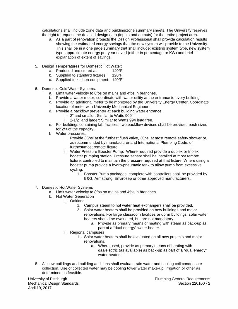
calculations shall include zone data and building/zone summary sheets. The University reserves the right to request the detailed design data (inputs and outputs) for the entire project area.
a. As a part of renovation projects the Design Professional shall provide calculation results showing the estimated energy savings that the new system will provide to the University. This shall be in a one page summary that shall include: existing system type, new system type, approximate energy per year saved (either in percentage or KW) and brief explanation of extent of savings.
5. Design Temperatures for Domestic Hot Water:
a. Produced and stored at: 140°F b. Supplied to standard fixtures: 120°F c. Supplied to kitchen equipment: 140°F
6. Domestic Cold Water Systems:
a. Limit water velocity to 8fps on mains and 4fps in branches. b. Provide a water meter, coordinate with water utility at the entrance to every building. c. Provide an additional meter to be monitored by the University Energy Center. Coordinate
location of meter with University Mechanical Engineer. d. Provide a backflow preventer at each building water entrance:
i. 2” and smaller: Similar to Watts 909 ii. 2-1/2” and larger: Similar to Watts 994 lead free.
e. For buildings containing lab facilities, two backflow devices shall be provided each sized for 2/3 of the capacity.
f. Water pressures: i. Provide 35psi at the furthest flush valve, 30psi at most remote safety shower or,
as recommended by manufacturer and International Plumbing Code, of furthest/most remote fixture.
ii. Water Pressure Booster Pump: Where required provide a duplex or triplex booster pumping station. Pressure sensor shall be installed at most remote fixture, controlled to maintain the pressure required at that fixture. Where using a booster pump provide a hydro-pneumatic tank to allow pump from excessive cycling.
1. Booster Pump packages, complete with controllers shall be provided by B&G, Armstrong, Envirosep or other approved manufacturers.
7. Domestic Hot Water Systems
a. Limit water velocity to 8fps on mains and 4fps in branches. b. Hot Water Generation
i. Oakland 1. Campus steam to hot water heat exchangers shall be provided. 2. Solar water heaters shall be provided on new buildings and major
renovations. For large classroom facilities or dorm buildings, solar water heaters should be evaluated, but are not mandatory.
a. Provide as primary means of heating with steam as back-up as part of a “dual energy” water heater.
ii. Regional campuses 1. Solar water heaters shall be evaluated on all new projects and major
renovations. a. Where used, provide as primary means of heating with
gas/electric (as available) as back-up as part of a “dual energy” water heater.
8. All new buildings and building additions shall evaluate rain water and cooling coil condensate
collection. Use of collected water may be cooling tower water make-up, irrigation or other as determined as feasible.

University of Pittsburgh Plumbing General Requirements Mechanical Design Standards Section 220100 - 3 April 19, 2017
a. For facilities that may require sump pumps to remove groundwater, collection and use of infiltrated water shall be reviewed.
9. Piping
a. All metal piping shall be certified by NSF, ANSI, CISPI per use of piping. Certifications shall be provided as part of the shop drawing submittal phase of the project and approved by the Design Professional.
b. General: i. Tee drilling copper piping is not acceptable. ii. Pipe Hangers shall meet MSS SP-58 as well as the following requirements:
1. Piping shall be supported to prevent sagging. 2. Piping shall not be supported from ductwork, conduit or other piping. 3. Piping shall be supported from the building structure using unistrut or
channel support system. iii. Pipe Seals: Where piping passes through exterior walls or waterproofed floors, a
sealing element manufactured from EPDM with interlocking links shall be used. Pipe seals shall be similar to PSI/Thunderline Link-Seal or Metraflex.
c. Aboveground Hot and Cold Water: i. Type L Copper meeting ASTM B88 ii. Fittings shall be wrought copper meeting ASME B16.22. iii. Pipe and fittings shall be joined by solder meeting ASTM B32. The solder shall be
a Tin-Antimony compound, Grade 95TA (95% Tin/5% Antimony). The use of solder containing lead is strictly prohibited.
d. Below ground Hot and Cold Water: i. 4” and smaller
1. Copper Type K meeting ASTM B88. 2. Fittings shall be wrought copper meeting ASME B16.22. 3. Pipe and fittings shall be joined using solder meeting ASTM B32. The
solder shall be a Tin-Antimony compound, Grade 95TA (95% Tin/5% Antimony). The use of solder containing lead is strictly prohibited. (I have used silver solder for this application, ask piping rep about use)
ii. 4” and larger 1. Class 52 cement lined ductile iron meeting AWWA C151. 2. Fittings shall be compact ductile iron pressure fittings coated and rated at
350 psi meeting AWWA C110/A21.10. 3. Joints shall be mechanical type with gland, neoprene gaskets, and 3/4" x 3-
1/2" bolts with nuts meeting AWWA C111/A21.11. e. Aboveground Sanitary Waste and Storm
i. Cast Iron hubless meeting ASTM A888 ii. Fittings shall be: cast iron meeting ASTM A888; iii. Cast iron pipe and fittings shall be joined using neoprene gaskets, heavy duty
stainless steel clamps and shield assemblies meeting ASTM A666. Gaskets shall be approved by pipe manufacturer to ensure compatibility.
f. Belowground Sanitary Waste, Storm and Vent. i. Cast Iron extra heavy weight hub and spigot meeting ASTM C-564 or ii. Ductile iron hub and spigot with rubber gaskets. iii. Fittings shall be cast or ductile iron heavy duty. iv. Cast iron pipe and fittings shall be joined using neoprene gaskets, heavy duty
clamps and shield assemblies meeting ASTM A666. Gaskets shall be approved by pipe manufacturer to ensure compatibility.
g. Aboveground Sanitary Vent i. Cast iron hubless service weight meeting A888. ii. Fittings shall be: cast iron meeting ASTM A888

University of Pittsburgh Plumbing General Requirements Mechanical Design Standards Section 220100 - 4 April 19, 2017
iii. Cast iron pipe and fittings shall be joined using neoprene gaskets and heavy duty stainless steel clamps. Gaskets shall be approved by pipe manufacturer to ensure compatibility.
h. Medical Gas Piping i. The minimum pipe size for oxygen, nitrous oxide, nitrogen, and medical
compressed air piping shall be 1/2". ii. All medical gas piping installation shall meet requirements of NFPA 99, latest
edition and International Plumbing Code, latest edition. iii. All medical gas brazers must be certified according to NFPA 99. A copy of the
certification must be available upon request. iv. Onsite cleaning shall be supervised by a member of the University staff. v. Piping Systems Materials:
1. Oxygen, Nitrous Oxide, Nitrogen, Medical Compressed Air and Vacuum Systems, Below Grade:
a. For all pipe sizes: i. Pipe shall be Type K seamless annealed soft copper tube
meeting ASTM B88 ii. Fittings shall be wrought copper meeting ANSI B16.22. iii. Joints shall be BCuP silver braze meeting AWS A5.8.
Ensure quality to avoid leaving excess flux on the interior off the joints.
iv. Piping shall be factory cleaned, purged and sealed and shall include labeling which reads “cleaned for medical gas service.”
2. Oxygen, Nitrous Oxide, and Nitrogen, Medical Compressed Air and Vacuum Systems, Above Grade:
a. For all pipe sizes: i. Pipe shall be Type K or Type L seamless hard drawn
copper tube meeting ASTM B819. ii. Fittings shall be wrought copper meeting ANSI B16.22. iii. Joints shall be BCuP silver braze meeting AWS A5.8. iv. Piping shall be factory cleaned, purged and sealed and
shall include labeling which reads “cleaned for medical gas service”.
vi. Refer to University Laboratory Design Manual for additional information. i. Laboratory Air and Vacuum Piping
i. The minimum pipe size for laboratory vacuum piping shall be 3/4". ii. The piping shall meet the requirements of the International Mechanical Code, latest
edition. iii. Piping Systems Materials:
1. Laboratory Air Piping: a. For pipe sizes 2" and smaller:
i. Pipe shall be: Schedule 40 galvanized steel meeting ASTM A53, Grade B; type K copper meeting ASTM B88; acrylonitrile-butadiene-styrene (ABS) plastic meeting ASTM D3965; or, high-density polyethylene (HDPE) plastic meeting ASTM D1248.
ii. Fittings shall be: malleable iron meeting ASME B16.3; wrought copper or copper alloy meeting ASME B16.22; ABS plastic meeting ASTM D3965; or, HDPE plastic meeting ASTM D1248.
iii. Joints shall be threaded, soldered, and solvent welded, or fusion welded.
iv. Some air compressor lubricating oils and oil additives cause deterioration of ABS piping. The Professional shall
University of Pittsburgh Plumbing General Requirements Mechanical Design Standards Section 220100 - 5 April 19, 2017
verify the suitability of ABS piping for a particular application before specifying its use.
v. ABS and HDPE piping, pipe fittings and pipe accessories have maximum pressure limitations at specific temperatures. The Professional shall verify the suitability of ABS and HDPE piping for each application’s pressure and temperature requirements before specifying its use.
b. For pipe sizes 2-1/2 inches and larger: i. Pipe shall be: Schedule 40 galvanized steel meeting
ASTM A53, Grade B; type K copper meeting ASTM B88; acrylonitrile-butadiene-styrene (ABS) plastic meeting ASTM D3965; or, high-density polyethylene (HDPE) plastic meeting ASTM D1248.
ii. Fittings shall be forged steel welding type meeting ASTM A234 wrought copper or copper alloy meeting ASME B16.22; ABS plastic meeting ASTM D3965; or, HDPE plastic meeting ASTM D1248.
iii. Joints shall be welded in accordance with AWS D1.1; soldered, solvent welded or fusion welded.
iv. Some air compressor lubricating oils and oil additives cause deterioration of ABS piping. The Professional shall verify the suitability of ABS piping for a particular application before specifying its use.
v. ABS and HDPE piping, pipe fittings and pipe accessories have maximum pressure limitations at specific temperatures. The Professional shall verify the suitability of ABS and HDPE piping for each application’s pressure and temperature requirements before specifying its use.
2. Laboratory Vacuum Piping: a. For all pipe sizes:
i. Pipe shall be: Type K or L hard drawn copper meeting ASTM B88.
ii. Fittings shall be wrought copper meeting ASME B16.22. iii. Joints shall be BCuP silver braze meeting AWS A5.8. iv. Alternately use stainless steel 304 ASTM A312 seamless
pipe schedule 40s with stainless steel fittings, flanges, bolts and nuts and all welded construction.
iv. The discharge from the vacuum pumps shall be vented to outdoors at the roof level. The discharge from vacuum pumps 1 HP and smaller may be vented into a laboratory exhaust air ductwork for discharge to outdoors.
v. The Professional shall provide acoustical enclosures around the vacuum pumps to reduce noise to the adjacent spaces even when the units are pre-purchased by the University.
vi. The Professional shall provide oil free air compressors and desiccant dryers for -40° F dew point with appropriate filtration for the laboratory air.
vii. Equipment like NMRs require 90 psig constant air pressure for proper operation. The air compressor/s shall be sized for 1/3 operating time and operate between 130 psig to 110 psig with a 10 psi pressure drop for accessories to deliver minimum 100 psig air pressure. The Professional shall provide compressed air flow diagram on the drawings. Duplex compressors may be provided for redundancy, if required by user.
1. Compressed air systems for other equipment shall be designed with the same methodology as above.
viii. The Professional should evaluate the need to put air compressor/s on emergency power based on discussions with users.

University of Pittsburgh Plumbing General Requirements Mechanical Design Standards Section 220100 - 6 April 19, 2017
ix. The Professional shall evaluate VFD drives for air compressors, provide to and receive direction from University Mechanical Engineer assigned to the project.
x. Pipe Identification – refer to Section 15112 for identification and color coding of pipes.
xi. Refer to University Laboratory Design Manual for additional information.
j. Laboratory Waste Piping i. The minimum pipe size for laboratory waste piping shall be 1-1/4”. ii. The piping system shall meet the requirements of International Plumbing Code,
latest edition. iii. The plumbing fixtures in the laboratories shall be provided with a drainage system
separate from the sanitary drainage system as per the University Laboratory Standards.
iv. The laboratory waste shall be controlled by an Owner program so that no waste acid or alkali is dumped to the drain system. The laboratory waste system will be connected to the sanitary waste system. Pit monitoring station and neutralizing tank on the laboratory waste will be provided only with the approval of the University’s Environmental Health and Safety Department.
v. The term “Acid Waste” for “Laboratory Waste” shall not be used on the drawings and specifications.
vi. Piping System Materials: 1. Laboratory Waste and Vent Piping, Below Grade:
a. For all pipe sizes: i. Pipe shall be Schedule 40 polypropylene, Orion (Blue)
pipe or equal. ii. Fittings shall be Schedule 40 socket fused
polypropylene. iii. Joints shall be heat fused for polypropylene pipe.
2. Laboratory Waste and Vent Piping, Above Grade: a. For all pipe sizes:
i. Pipe shall be Schedule 40 polypropylene. Orion (Blue) pipe or equal.
ii. Fittings shall be grooved Schedule 40 polypropylene iii. Joints shall be mechanical type with stainless steel
compression clamps for polypropylene pipe. vii. Refer to University Laboratory Design Manual for additional information.
k. Compressed Air Piping i. The minimum pipe size for compressed air piping shall be 1/2". ii. The piping shall meet the requirements of ASPE and International Plumbing Code,
latest edition. iii. The Professional shall provide schematic piping diagram for the compressed air
system on the construction design drawings. The diagram shall include all filtering, cooling, drying and pressure regulating requirements.
iv. The air compressors shall be sized for 1/3 operating time for the total system compressed air requirements. Dual compressors shall be provided in case one compressor fails.
v. Piping Systems Materials: 1. Compressed Air Piping:
a. For pipe sizes 2" and smaller: i. Pipe shall be: Schedule 40 galvanized steel meeting
ASTM A53, Grade B; type K copper meeting ASTM B88; acrylonitrile-butadiene-styrene (ABS) plastic meeting ASTM D3965; or, high-density polyethylene (HDPE) plastic meeting ASTM D1248.

University of Pittsburgh Plumbing General Requirements Mechanical Design Standards Section 220100 - 7 April 19, 2017
ii. Stainless steel pipe and fittings may be used in lieu of steel or copper: Pipe shall be ASTM A312, Schedule 10S, Type 304/304L stainless steel with plain ends. Fittings shall be precision, cold drawn, stainless steel with elastomer O-ring seals, suitable for working pressure to 500-psig (3450-kPa).
1. Vic Press stainless steel joints and fittings shall be allowed when used with stainless steel piping.
iii. Fittings shall be: malleable iron meeting ASME B16.3; wrought copper or copper alloy meeting ASME B16.22; ABS plastic meeting ASTM D3965; or, HDPE plastic meeting ASTM D1248.
iv. Joints shall be threaded, soldered, solvent welded, or fusion welded.
v. Some air compressor lubricating oils and oil additives cause deterioration of ABS piping. The Design Professional shall verify the suitability of ABS piping for a particular application before specifying its use.
vi. ABS and HDPE piping, pipe fittings and pipe accessories have maximum pressure limitations at specific temperatures. The Design Professional shall verify the suitability of ABS and HDPE piping for each application’s pressure and temperature requirements before specifying its use.
b. For pipe sizes 2-1/2 inches and larger: i. Pipe shall be: Schedule 40 galvanized steel meeting
ASTM A53, Grade B; type K copper meeting ASTM B88; acrylonitrile-butadiene-styrene (ABS) plastic meeting ASTM D3965; or, high-density polyethylene (HDPE) plastic meeting ASTM D1248.
ii. Fittings shall be forged steel welding type meeting ASTM A234 wrought copper or copper alloy meeting ASME B16.22; ABS plastic meeting ASTM D3965; or, HDPE plastic meeting ASTM D1248.
iii. Joints shall be welded in accordance with AWS D1.1; soldered, solvent welded or fusion welded.
iv. Some air compressor lubricating oils and oil additives cause deterioration of ABS piping. The Design Professional shall verify the suitability of ABS piping for a particular application before specifying its use.
v. ABS and HDPE piping, pipe fittings and pipe accessories have maximum pressure limitations at specific temperatures. The Design Professional shall verify the suitability of ABS and HDPE piping for each application’s pressure and temperature requirements before specifying its use.
vi. Victaulic Style 905, 907, and 908 installation-ready joints may be used in exposed areas and above lay-in type ceilings.
vi. Refer to University Laboratory Design Manual for additional information. l. Natural Gas
i. 2” and smaller: 1. Schedule 40 steel (ASTM 53) with malleable-iron threaded fittings and
threaded joints.

University of Pittsburgh Plumbing General Requirements Mechanical Design Standards Section 220100 - 8 April 19, 2017
ii. 2-1/2” and larger: 1. Schedule 40 steel (ASTM 53) with steel welded fittings and welded joints.
iii. Outdoor piping shall be painted with rust inhibitor, color to match Design Manual Section 230553.
iv. Underground piping shall be stainless steel gas tubing encased in conduit vented to the exterior of the building.
v. Natural gas piping shall not be buried under a building. m. Condensate from HVAC equipment
i. Type L Copper. ii. Ensure there are no trip hazards created by pipe routings.
n. Foundation/Footing Drains: i. For all pipe sizes:
1. Pipe shall be SDR 35 perforated PVC meeting ASTM D3033 or D3034. 2. Fittings shall be PVC meeting ASTM D3033 or D3034. 3. Pipe and fittings shall be joined using elastomeric gaskets meeting ASTM
F477. o. All piping shall be pressure tested.
i. Sanitary and Storm piping shall be hydrostatically tested, pressure shall be determined by Design Professional.
ii. Design Professional shall recommend method and pressure of testing of all other piping systems.
10. Valves: a. General:
i. Shut off (isolation) valves shall be provided on inlet and outlet, to each piece of plumbing equipment item and on supply to each plumbing fixture.
1. Shall be full port ball valve, quarter turn, bubble tight shutoff. ii. Isolation valves shall be provided at each floor take-off and branch take-offs
serving 3 or more plumbing fixtures or pieces of equipment. 1. Shall be full port ball valves with quarter turn, bubble tight shutoff.
iii. Drain valves 1. Shall be provided on each plumbing equipment item located so as to allow
full drainage of equipment for service and repair. 2. Shall be provided at base of each riser, at low points of horizontal runs,
and where required to allow drainage of water distribution piping system. 3. Shall be quarter turn, ball valve with hose end connection, hose end cap
and chain. 4. Coordinate floor drains with equipment to allow proper drainage.
iv. Stop and waste valves shall be provided on branch piping upstream of hydrants and hose bibbs.
v. Spring loaded check valves shall be provided on discharge side of pumps. vi. Swing check valves shall be provided in hot water recirculation systems to direct
flow. vii. Check valves shall be provided on domestic water piping (hot and cold) serving each
janitor’s closet mop basin and each ice machine. viii. All butterfly valves shall be of lug type, unless noted otherwise herein.
b. Throttling Valves: i. Shall be Globe or v-port type Ball valve. ii. Other valve types for this service must be approved by the University Mechanical
Engineer assigned to the project. c. Pump Discharge Check Valves:
i. For 2-inches NPS and smaller, swing check valves. ii. For 2 1/2-inches NPS and larger, non-slam wafer-style plate check valves.
d. Acceptable manufacturers: i. Globe, ball and drain valves:

University of Pittsburgh Plumbing General Requirements Mechanical Design Standards Section 220100 - 9 April 19, 2017
1. Shall be Watts, Crane, Stockham, Jamesbury, W-K-M, Jenkins, Milwaukee, Nibco, Conbraco, Lunkenheimer, or approved equal.
ii. Natural gas check valves: 1. Dezurik, Milliken or approved equal.
iii. Butterfly valves for domestic hot and cold water: 1. Center Line, Watts, Milwaukee, Jamesbury, Conbraco, Crane, Stockham,
Lunkenheimer, or approved equal. iv. Pressure reducing, safety relief valves and safety valves:
1. Watts Regulator Co., Bell & Gossett, Leslie Controls Inc., Lonergran Valve Division, Kunkle Valve Division, Spirax-Sarco, and Spence Engineering Co.
11. Valve Product Specifications:
Legend: CI – Cast Iron
CS - Carbon Steel SS – Stainless Steel ISRS - Inside Screw Rising Stem OS & Y - Outside Screw and Yoke CMP – Composition RPTFE – Reinforced PTFE Domestic Cold Water: (1) Valve Type: Gate (Underground) Size Class Body Trim Body Operator Material Seat Disk Connect 4" & UP: 250 Ductile Iron SS Iron Mech. Jt. ISRS (2) Valve Type: Ball Size Class Body Trim Body Operator Material Seat Disk Connect 2" & DN: 600 CWP Bronze RPTFE SS Screwed Lever
(3) Valve Type: Butterfly Size Class Body Trim Body Operator Material Seat Disk Connect 2-1/2" & UP: 300 CI or DI EPDM CS or SS Lugged Gear (4) Valve Type: Globe Size Class Body Trim Body Operator Material Seat Disk Connect 2-1/2" & UP: 150 CCS CCS CCS Flanged OS & Y 2" & DN: 200 CWP Bronze SS SS Screwed ISRS (5) Valve Type: Check Size Class Body Trim Body Operator Material Seat Disk Connect 2-1/2" & UP: 150 CI or CS Bronze CI Flange non-slam spring assisted 2" & DN: 200 CWP Bronze Bronze Bronze Screwed Swing

University of Pittsburgh Plumbing General Requirements Mechanical Design Standards Section 220100 - 10 April 19, 2017
Service: Equipment Drains, Condensate, Solar, Heat Recovery (Standard Pressure): (2) Valve Type: Ball Size Class Body Trim Body Operator Material Seat Disk Connect 2" & DN: 600 CWP Bronze RPTFE SS Screwed Lever (2) Valve Type: Butterfly Size Class Body Trim Body Operator Material Seat Disk Connect 2-1/2" & UP: 150 CCS CS CS Lugged Lever a. Service: Natural Gas (1) Valve Type: Plug Size Class Body Trim Body Operator Material Seat Disk Connect All: 175 CI Rubber Steel Screwed Key (2) Valve Type: Double Door Check Size Class Body Trim Body Operator Material Seat Disk Connect 2-1/2 & UP: 125 DI or SS EPDM SS Flanged None
12. Backflow preventers shall be installed no more than 5 feet above floor and shall be readily
accessible. Professional shall make provisions that the water can be shut down to the facility during a 4 to 8 hours duration for annual inspection of reduced pressure type backflow preventers. If the water cannot be shut down to the facility, provide a second set of back flow preventers or bypass as standby based on the functionality of the building. Provide necessary accessories for testing of each back flow preventer separately without shutting the service to the building. Drain from backflow to be routed to nearest drain or daylight to exterior; coordinate exterior drain with University Project Manager.
13. HVAC and other non-potable water system connections shall be provided with a code compliant
backflow prevention device.
14. Use of pro-press type of piping connections is not permitted.
15. Water purification systems: The Engineer shall discuss the intent and approach of the design with the University prior to the start of the design.
16. Pure water systems (RO and/or DI): a. All pure water systems shall be looped. b. The system shall be designed to eliminate stagnation. Every branch shall have a re-circulated
return. c. The piping for de-ionized water shall be stainless steel 304 of all welded construction,
schedule 40 polypropylene or PVDF piping. i. Proper valving, gaskets, insulation and accessories shall be provided to match
needs of system.

University of Pittsburgh Plumbing General Requirements Mechanical Design Standards Section 220100 - 11 April 19, 2017
17. The Professional shall provide cold and hot water pipe riser diagrams for all new work connecting to the existing systems and for new facilities. Show all required shock absorbers.
18. The Professional shall provide waste and vent pipe riser diagrams for all new work connecting to the existing systems and for new facilities. Provide invert elevations of sanitary drains.
19. The Professional shall provide fixture load calculations on the drawings for new facilities and for renovations to evaluate new and existing sizing of cold and hot water piping systems.
20. Pipe Identifications: All piping systems shall be provided with the University’s standard identification symbols and colored code banding as listed under Division 23 guidelines.
21. The Lavatory fixtures shall be battery operated auto sensing type with 0.5 GPM aerators.
22. Hot water systems shall include recirculation loops. Dead legs shall be kept to a minimum.
Recirculation pumps over 2 HP shall use a variable frequency drive and differential pressure sensors at the furthest point in the system.
a. Wait time at fixtures for hot water shall be kept to a maximum of 10 seconds. b. Packaged Digital Mixing Valves may be used in lieu of thermostatic mixing valves where low
flow conditions dominate the use of the hot water system.
23. The contents of ALL storage tanks must be prominently displayed on the tank.
24. Domestic water systems shall include Legionella risk reduction measures as suggested by ASHRAE Standard 188 latest edition.
25. When removing domestic water piping service fixtures or equipment, remove all piping back to nearest active main pipe to avoid stagnation.
26. Plumbing fixtures shall not be installed above electrical rooms, tele/data or security closets.
27. Provide freeze proof wall hydrants on exterior walls at a maximum of 150 feet apart, at loading docks, near any outdoor mechanical equipment, at least one on exterior wall of penthouses with adjacent accessible roofs. Height of hydrant shall be above the snow line.
28. Water Hammer Arrestors shall be certified by the PDI.
29. Sanitary Piping buried beyond 5’-0“of building: Piping shall be in accordance with the requirements
of the City of Pittsburgh or the requirements of the local Authority Having Jurisdiction (AHJ).
30. Sanitary and Vent buried within 5'-0" of building: Piping shall be in accordance with the requirements of the City of Pittsburgh or the requirements of the local Authority.
a. Building traps are prohibited by International Plumbing Code Section 1002.6 except where required by the Local Authority Having Jurisdiction. In case a building trap is provided, it shall be equipped with at least one, preferably two clean-outs and a relief or fresh air vent on the inlet side of the trap. The relief or fresh air intake shall be carried above the grade outside the building and terminate with a screened outlet. Coordinate with the AHJ providing sewer service to the building.
31. All plumbing fixtures for the rest rooms shall be wall mounted. Floor mounted fixtures shall only be
permitted with University Architect approval.
32. All rest rooms shall be provided with at least one floor drain. This shall include single fixture rest rooms.

University of Pittsburgh Plumbing General Requirements Mechanical Design Standards Section 220100 - 12 April 19, 2017
33. Trap seals of floor drains subject to loss by evaporation shall be provided with trap seal primer valve as per International Plumbing Code.
34. Condensate from the cooling coils should not be connected to the storm conductor. Condensate from
the cooling coils may be contaminated, as such it is considered non-potable waste by the University and should be discharged thru the waste/sanitary system.
a. Unless being reclaimed for other purposes. b. Condensate recovery shall be evaluated for reclamation for use in other systems.
35. Storm
a. The minimum pipe size for aboveground storm drainage piping shall be 3". The minimum pipe size for underground storm drainage piping shall be 4".
b. Minimum size of roof drain shall be 3”. c. The drainage system shall meet the requirements of International Plumbing Code, latest
edition. d. Secondary roof drains (emergency) shall be provided as per International Plumbing Code. e. Pipe Sizing:
i. The storm drainage system shall be sized for 100 year hourly rainfall rate for University’s various campuses per the latest edition of the International Plumbing Code.
36. The minimum pipe size for underground sanitary piping shall be 4".
37. Flush valves shall be electronic and hard wired for urinals.
38. Faucets shall be automatic and hard wired in all public restroom facilities.
39. Low flow fixtures
a. Pint flush urinals shall be used in all gang toilets. b. Use of low flow toilets shall be evaluated during design and used where approved by
University Mechanical Engineer assigned to the project. c. Lavatories shall be low flow, 0.5gpm is ideal.
i. Though to minimize wait for hot water recirculation point of use heaters shall be evaluated as part of design.
40. Maintenance Staff Safety a. Access to all pumps, motors, valves etc. that require maintenance, at least yearly per
equipment manufacturer O&M’s, shall be provided with adequate means of access. b. Unacceptable access conditions:
i. Crawling under or stepping on or over ductwork/piping. ii. Access outboard of exterior railings or other fall protection means. iii. Greater than four feet above ceilings, unless approved by University Project
Manager and University Operations.
41. “AS-BUILT” DRAWINGS, TRAINING, AND O&M MANUALS a. The Professional shall specify that, during the course of the work, the Contractor shall record
all changes in the work on a set of the contract documents (in electronic format) to include one (1) set of corrected specifications. The Professional shall revise the original documents and provide the “As-Built” information in computer file form (PDF and DWG) to the University. This applies to all Trades involved with the work.
b. The Professional shall specify that training sessions for each piece of plumbing equipment or each plumbing system shall be a minimum of eight hours each. Training shall not be held until the start-up and commissioning of the subject electrical equipment or system is complete.

University of Pittsburgh Plumbing General Requirements Mechanical Design Standards Section 220100 - 13 April 19, 2017
c. The date of substantial completion of the construction contract takes effect on the date when both the required training and O&M manuals have been fully received.
d. All major plumbing equipment (including but not limited to water heaters, heat exchangers, domestic booster stations, RODI systems, vacuum pumps, air compressors and VFDs) shall have a warranty label placed in a conspicuous place. Label shall indicate start and end date of the warranty period. The start date shall be the date of final acceptance by the University. Warranty must also be included in the O&M Manuals.
42. Plumbing Fixture Basis of Design:
a. Electric Water Coolers i. Wall hung w/ bottle filler (no filter or filter indicator light) ii. Oasis Model PGF8EBFSL
b. Floor Drains i. Zurn
c. Flushometer i. Sloan Automatic with side mount sensor
d. Flush Valve i. Sloan Model 186-1.0
e. Ionization Unit i. Liquitec or equal.
f. Lavatories i. Comrade 0124-024 (White 020)
g. Service Sink i. Basin – Zurn Model Z1996-36 ii. Faucet – Chicago Faucet No 897
h. Sink Faucets i. Symmetrix S-20
i. Urinal i. Wall Hung, Automatic Hardwired – Pint Flush ii. American Standard ‘Washbrook Flowise’
j. Water Closets i. Wall hung, automatic hardwired, 1.6 GPF ii. American Standard AFW A2#2477016 (White 020)
43. Plumbing Equipment Allowed Manufacturers:
a. Steam to Domestic Hot Water Heaters i. Shall be Bell and Gossett, PVI, Spirax Sarco, Leslie, Aerco or Armstrong.
b. Booster Pumps i. ITT, Grundfos, Taco, Goulds
c. Gas Water Heaters i. AO Smith, Bradford White, State, Lochinvar
d. Backflow Preventers i. Hersey, Watts, Zurn.
e. Drinking Fountains i. Oasis, Elkay, Halsey Taylor, Haws
f. Lavatories i. American Standard, Eljer, Kohler, Crane, Zurn
g. Sink Faucets i. Symmetrix, American Standard, Chicago Faucet, Kohler
h. Water Closets i. American Standard, Eljer, Kohler, Crane, Zurn
i. Urinals i. American Standard, Eljer, Kohler, Crane, Zurn
j. Flush Valves i. Sloan, Zurn, Gebriet, approved equals
University of Pittsburgh Plumbing General Requirements Mechanical Design Standards Section 220100 - 14 April 19, 2017
k. Thermostatic Mixing Valves i. Leonard, Powers, Bradley, Symmons, Lawler
l. Digital Mixing Valves – Packaged System i. Powers
m. Sinks i. Elkay, Moen, Advance Tabco
n. Mop Basins i. Crane, Florestone, Stern-Williams, Zurn
o. Hose Bibbs, Wall Hydrants i. Josam, Smith, Woodford, Zurn, Mifab
p. Emergency Eyewash and Combination Fixtures i. Bradley, Encon, Haws, Speakman
q. Outlet Boxes i. IPS, Oatey, Symmons, approved equals.
r. Water Hammer Arresstors i. Josam, PPP, Zurn, MiFab
s. Additional manufacturers may be used when product more closely matches the intended use. These shall be coordinated with the University Project Manager and University Mechanical Engineer assigned to the project.
44. Monitoring and Controls
a. All equipment and systems shall be monitored by the existing Campus control system via BACnet interface. Minimum control points and graphics shall be provided for the following. Additional may be necessary depending on the scope of the project.
i. Domestic Hot Water System 1. Supply temperature 2. Return temperature 3. Mixed temperature (if using a thermostatic mixing valve) 4. Building supply pressure 5. Recirculation loop pump status 6. Power draw from recirculation pump. 7. Water Heater status 8. Alarms for all equipment.
ii. Domestic Cold Water System 1. Building supply pressure 2. Supply temperature 3. Building Flow Meter 4. Flow meter for Process Water systems, HVAC make-up water, closed loop
HVAC, etc. 5. Booster pump inlet and outlet pressures 6. Booster pump status 7. Sump and Ejector Pump status 8. Alarms for all equipment.
END OF SECTION

University of Pittsburgh Mechanical General Requirements Mechanical Design Standards Section 230100 - 1 April 19, 2017
UNIVERSITY OF PITTSBURGH MECHANICAL DESIGN STANDARDS SECTION 230100 - MECHANICAL GENERAL REQUIREMENTS
1. The design requirements contained in this tab (Division 23) shall be employed for every project. Approval must be obtained from the University of Pittsburgh Mechanical Engineer assigned to the project for any deviations made from the design requirements contained in this division. The design requirements herein shall be used as the bare minimum requirements.
2. Codes and Standards: The Design Professional shall comply with the requirements of all applicable codes and standards for each specific design project. The latest editions at the time of the Schematic Design submittal shall govern edition of standards to be used.
a. International Building Code (latest edition) b. International Mechanical Code (2015) c. International Plumbing Code 2015) d. International Fire Code (latest edition) e. International Fuel Gas Code (2015) f. International Energy Conservation Code (2015) g. National Fire Protection Association (NFPA) Standards (latest editions) h. Pennsylvania Department of Labor and Industry i. ASHRAE Standards (2013 or latest editions), including but not limited to:
i. 90.1-Energy Standard for Buildings Except Low-Rise ii. 55-Thermal Environmental Conditions for Human Occupancy iii. 62.1-Ventilation for Acceptable Indoor Air Quality iv. 188-Legionellosis: Risk Management for Building Water Systems. v. 15-Safety Standard for Refrigeration Systems vi. 52.2-Method of Testing General Ventilation Air-Cleaning Devices
j. Pittsburgh Water and Sewer Authority, for Oakland Campus only k. National Electrical Code (latest edition) l. American Society of Mechanical Engineers m. American Assoc. for Accreditation of Laboratory Animal Care (AAALAC) n. National Institute of Health (NIH) o. American Institute of Architects (AIA) p. Sheet Metal & Air-conditioning Contractors National Assoc. (SMACNA) q. American Conference of Governmental Industrial Hygienists(ACGIH) r. American National Standard Institute (ANSI) s. American Society of Testing and Materials (ASTM) t. Other as determined by Authority Having Jurisdiction
3. Outdoor Design Temperatures:
a. The following outdoor air temperatures shall be used for the purpose of calculating space and/or block heating and cooling loads:
i. Winter Outdoor Air Dry Bulb Design Temperatures: 1. Oakland Campus: 2° F 2. Johnstown Campus: 3° F 3. Greensburg Campus: 2° F 4. Titusville Campus: 2° F 5. Bradford Campus: -6° F
ii. Summer Outdoor Air Dry Bulb and Wet Bulb Design Temperatures: (too more closely match ASHRAE 0.4% conditions)

University of Pittsburgh Mechanical General Requirements Mechanical Design Standards Section 230100 - 2 April 19, 2017
1. Oakland Campus: 91° FDB/72° FWB 90/73 (evaporation 75WB 85F Mean Coincident Dry Bulb)
2. Johnstown Campus: 86° FDB/70° FWB 86/71 (evaporation 73WB 82F Mean Coincident Dry Bulb)
3. Greensburg Campus: 91° FDB/72° FWB 90/73 (evaporation 75WB 85F Mean Coincident Dry Bulb)
4. Titusville Campus: 89° FDB/71° FWB 88/73 (evaporation 75WB 84F Mean Coincident Dry Bulb)
5. Bradford Campus: 87° FDB/71° FWB 84/69 (evaporation 72WB 80F Mean Coincident Dry Bulb)
b. The following outdoor air temperatures shall be used for selecting HVAC equipment.
i. Cooling Towers and Evaporative Condensers/Condensing Units: 1. Oakland Campus: 78° FWB 2. Johnstown Campus: 78° FWB 3. Greensburg Campus: 78° FWB 4. Titusville Campus: 78° FWB 5. Bradford Campus: 78° FWB
ii. Air Cooled Chillers, Air Cooled Condensing Units and Packaged Air Conditioning Units: (all ASHRAE 0.4% DB are below 90 for all campuses)
1. Oakland Campus: 95° F 2. Johnstown Campus: 95° F 3. Greensburg Campus: 95° F 4. Titusville Campus: 95° F 5. Bradford Campus: 95° F
4. Indoor Air Design Conditions: The following indoor air temperatures shall be used for the
purpose of calculating block and/or space heating and cooling loads as well as initial system setpoints.
a. Winter Indoor Air Dry Bulb Temperatures i. All occupied spaces: 70º F ± 2º F. ii. Labs housing and caring for animals: As required by the current edition
of “Guide for Care and Use of Laboratory Animals”. Confirm with University PM prior to design.
iii. Unoccupied spaces (such as storage rooms, vestibules, etc.): 55ºF ± 5º F
iv. Unoccupied spaces (such as mechanical equipment rooms, electrical equipment rooms, etc.): 55ºF minimum.
v. Unoccupied spaces (such as toilet rooms): 68º F ± 2º F. vi. Elevator equipment rooms: 40°F minimum and 90º F maximum.
b. Summer Indoor Air Dry Bulb and Wet Bulb Temperatures: i. All occupied spaces: 74º F ± 2º F with maximum 57º F WB ii. Labs housing and caring for animals: As required by the current edition
of “Guide for Care and Use of Laboratory Animals”. Confirm with University PM prior to design.
iii. Unoccupied spaces (such as storage rooms, vestibules, etc.): 80ºF ± 5º F with maximum 62º F WB.
iv. Unoccupied spaces (such as mechanical equipment rooms, electrical equipment rooms, etc.): 90ºF maximum, non-condensing conditions at all times.
v. Unoccupied spaces (such as toilet rooms): 78º F ± 2º F with maximum 57º F WB.
vi. Elevator equipment rooms: 40°F minimum and 90º F maximum, non-condensing conditions at all times.

University of Pittsburgh Mechanical General Requirements Mechanical Design Standards Section 230100 - 3 April 19, 2017
c. Indoor Air Winter Design Humidity Levels:
i. The following humidity levels shall be maintained for the spaces as listed:
1. General laboratory spaces: 25% RH ± 10% 2. Labs housing and caring for animals: As required by the current
edition of “Guide for Care and Use of Laboratory Animals”. Confirm with University PM prior to design.
3. Computer rooms: 30% RH ± 5% minimum and 55% RH ± 5% maximum.
5. Supply Air Temperature: a. Heating supply air temperatures shall be no more than 15°F above room design
set point. i. Where supply air temperatures are required to be 15°F above space set
point, the ventilation air volume shall be adjusted upwards per ASHRAE 62.1.
b. Cooling air supply air temperatures shall be a maximum of 55°F. Lower temperatures shall be used when lower than normal humidity levels are required.
i. Supply air temperatures shall be allowed to reset upwards when the wet bulb temperature allows for humidity levels to be maintained at a maximum of 50%.
6. Ventilation Requirements: a. The design of HVAC systems shall incorporate the introduction of outdoor air
meeting or exceeding the minimum quantity required by the latest edition of the either the International Mechanical Code or ASHRAE Standard 62, whichever is more stringent.
b. All air handling equipment and packaged air conditioning equipment shall be provided with an integral economizer in order to take advantage of free cooling as required by ASHRAE 90.1 requirement.
c. For ventilation of laboratories and animal areas, refer to the University’s Laboratory Standards.
d. Outdoor Air Intakes: Outdoor air intakes for HVAC systems shall be located at a minimum distance from building exhaust outlets, flues from gas-fired equipment, plumbing vents, etc as per ASHRAE Standards and International Mechanical Code.
i. For the Oakland campus, all air intakes shall be a minimum of 15’ above street level.
e. Demand Control Ventilation: i. Occupancy counters similar to Ebtron CENSus or approved equal shall
be used in all conference rooms, meetings rooms, classrooms and other high occupancy locations.
ii. Alternate methods of demand control ventilation shall be suggested by the Professional based on the scope of each project.
iii. Refer to ATC Section 230900 for Sensor information.
7. Sound Pressure Level Requirements: a. HVAC systems shall be designed to limit the noise transmitted to occupied
spaces. Listed below are maximum allowable Noise Criterion (NC) levels for various spaces.
i. General offices: 35 ii. Executive offices: 30 iii. Conference rooms and teleconference room: 30 iv. Corridors and public areas: 40

University of Pittsburgh Mechanical General Requirements Mechanical Design Standards Section 230100 - 4 April 19, 2017
v. Computer rooms and research laboratories: 40 vi. Classrooms: 30 vii. Libraries and auditoriums: 25 viii. Gymnasiums: 45
b. The sound pressure levels around mechanical and electrical equipment (boilers, fans, pumps, pressure reducing valves, motors, turbines, elevators, transformers, etc.) in the equipment spaces shall not exceed 85 dBA on the A scale at any point three feet from the equipment with all the equipment in the room operating simultaneously.
i. Spaces unable to meet this criteria shall be reviewed by University and proper steps will be taken to ensure OSHA safety standards are followed as well as proper use of adjacent spaces. These spaces shall be identified on the drawings.
c. The professional shall provide sound rating of each piece of equipment that may contribute noise to the space being air conditioned. Professional shall provide means to attenuate the equipment noise so that it does not result in NC levels above the required levels above.
d. The professional shall coordinate noise reduction methods with University Engineer.
i. The primary means of noise reduction on air handling systems shall be thru air handling unit sizing, fan sizing and air velocities thru ductwork and diffusers.
ii. Duct liner use shall be kept to a minimum. When used for noise control is shall be provided with a perforated internal liner. All edges shall be protected from the airstream. Liners shall have a mold resistant coating approved by ASTM or another recognized agency to prevent the growth of mold and mildew.
iii. Sound Attenuators shall be used if circumstances require. Special attention shall be given to velocities and air pressure drops thru attenuators.
iv. The Testing and Balancing Sub-contractor shall be specified to provide sound readings for critical areas and included in their TAB report. These spaces shall be discussed and identified during the design process.
v. All equipment installed exterior to a building shall be analyzed for their noise impact on building occupants, adjacent building occupants and, where applicable, pedestrian traffic.
8. Calculations: For each project, a copy of all HVAC/Energy, manual and computerized, calculations shall be submitted to the University when drawings are submitted for the DD drawing and specifications submittal; then again for the 95% construction drawings and specifications review and approval. Computerized calculations shall include zone data and building/zone summary sheets. The University reserves the right to request the detailed design data (inputs and outputs) for the entire project area.
a. Fan static and pump head calculations shall be included. b. Friction loss for steam piping shall be provided. c. Interior Spaces with greater than 0.7CFM/Sqft shall be provided with
documentation as to why (excluding labs and classrooms). Minimizing interior zone reheat energy is a big concern on campus.
d. As a part of renovation projects the Design Professional shall provide calculation results comparing the existing space/building Energy Usage Intensity (EUI) with the estimated EUI that the new system will achieve. This shall be in a one page summary that shall include: existing system type, new system type, existing space EUI and new EUI with a brief explanation of reasoning and extent of savings. Calculation detail including Inputs/Outputs shall also be included in the submission.

University of Pittsburgh Mechanical General Requirements Mechanical Design Standards Section 230100 - 5 April 19, 2017
i. Existing EUI shall be provided by the University. ii. A blended EUI can be used when dealing with renovations in existing
buildings handling multiple space types. e. Energy Use Intensity targets for new and renovated spaces.
i. The energy targets reflect total metered energy inputs, including but not limited to chilled water, steam, gas and electricity serving heating, cooling, dehumidification, humidification, ventilation, process energy, domestic water heating, lighting, and receptacle loads.
1. Offices: 100 kbtu/gsf/yr 2. Classrooms: 100 kbtu/gsf/yr 3. Labs: 200 kbtu/gsf/yr 4. Residence Halls: 100 kbtu/gsf/yr
f. Prior to starting calculations the Design Professional shall request the latest utility costs for all systems to be used on the project (Chilled Water, Steam, Electricity, Natural Gas etc).
9. Heat Generation:
a. Oakland Campus: heat generation, year round, shall be steam fed from the Bellefield Boiler Plant and/or Carrillo Street Steam Plant unless otherwise directed by the University (by the Mechanical Engineer assigned to the project). Steam is available at 175 psig. Every building shall utilize a 2 stage pressure reducing station, dropping to 50psi then to 15psi for use in the building. Refer to Section 232113 for additional information.
i. Steam coils shall be sized for 5 psi entering steam. ii. Steam control valves shall be selected such that a minimum of 5 psi is
available entering steam coils. iii. Oakland Campus Building’s hot water systems shall be designed to
operate on a 40-degree delta-T from 180F to 140F. 1. Perimeter heating hot water may use temperature resets,
especially when on/off type control valves are used on the perimeter heat.
b. All Regional Campuses: heat generation for each facility shall be via gas fired condensing boilers. Boilers shall be sized to take advantage of condensing boiler efficiencies and for use as means of reheat. Reheat coils in air system shall be sized appropriately.
i. Hot water systems shall operate at a minimum of a 40-degree delta-T. Recommended 160F to 120F in heating mode and 120F to 80F for reheat mode.
ii. When steam is required, low pressure steam boilers shall be provided. iii. Steam for building specific processes shall be provided by dedicated
steam generation units, especially where high pressure steam is required. Steam boilers for building use will be provided only under written direction from the University.
c. Electric heat may only be used under extenuating circumstances and must be approved by University Mechanical and Electrical Engineers.
10. Cooling Generation:
a. Oakland and Johnstown Campuses: Building air conditioning systems shall be designed for chilled water, which shall be obtained from the campus central chilled water systems unless specifically approved otherwise by the University (directed by the Mechanical Engineer assigned to the project).
i. Building chilled water systems shall be designed to operate at a 15-degree delta-T from 42F to 57F.
b. Greensburg, Titusville and Bradford Campuses: cooling generation for each facility shall be via electric driven equipment. Chillers shall use a minimum of a

University of Pittsburgh Mechanical General Requirements Mechanical Design Standards Section 230100 - 6 April 19, 2017
15-degree delta-T (42F to 57F). Chiller efficiency shall be the main determining factor during chiller selection.
c. Use of direct-expansion cooling shall only be allowed where use of chilled water is unavailable, cost prohibitive or does not present a payback of 10 years or less. Approval from the University Mechanical Engineer assigned to project is required.
i. Direct expansion may be used as a secondary means of cooling for chilled water systems requiring redundancy.
11. Personnel Training: At the completion of a project, training shall be provided for
University maintenance personnel to educate the personnel on the operation and maintenance of the mechanical systems and equipment, including the automatic temperature control system, installed under that project. The Design Professional shall coordinate the amount of training which shall be provided by the HVAC, plumbing and fire protection contractors for each project with the University's Project Manager (Mechanical Engineers assigned to the project) to allow for incorporation in the final project specifications. Refer to individual Design Manual Sections for full training requirements.
12. Maintenance Staff Safety a. Access to all filters, dampers, fans, motors, control valves etc. that require
maintenance, at least yearly per equipment manufacturer O&M’s, shall be provided with adequate means of access.
b. Unacceptable access conditions: i. Crawling under or stepping on or over ductwork/piping. ii. Access outboard of exterior railings or other fall protection means. iii. Greater than four feet above ceilings, unless approved by University Project
Manager and University Operations.
13. Acceptable Manufacturers: A minimum of 3 manufacturers shall be listed in the specifications for each major piece of mechanical equipment, unless otherwise directed by University Mechanical Engineer assigned to the project. In some situations one or two manufacturers may be provided due to size restrictions, performance capability or to match existing units/systems. University preferred manufactures are listed in Section 238000 of the design manual.
14. Energy Conservation:
a. The University is interested in all energy conserving opportunities. All energy conservation measures shall be reviewed with, and approved by the University in the Schematic Design phase of each project.
b. The Professional shall evaluate and provide energy recovery as per ASHRAE Standard 90.1-2016 on any system that exhausts air.
c. All 3-phase motors shall be provided with a VFD. d. All single phase motors shall be ECM type and be provided with a speed
controller. Refer to Section 230513 for additional motor requirements.
15. Energy Rebates: a. The University seeks opportunities for energy rebates through our electric utility
provider, Duquesne Light. i. Renovation projects that provide higher efficiency equipment and
systems shall be detailed enough such that the existing equipment power requirements are noted on the drawings. New power requirements shall be provided for on the drawings. This information shall be included for installation of VFD’s, higher efficiency cooling systems, heat recovery systems, etc.
ii. New projects shall meet all energy efficiency goals set by the University.

University of Pittsburgh Mechanical General Requirements Mechanical Design Standards Section 230100 - 7 April 19, 2017
16. Mechanical equipment shall be located indoors unless the University Mechanical
Engineer AND University Architect approve outdoor installations.
17. For Mechanical Equipment Room requirements, refer to Specification Section 230500 Basic Materials and Methods.
18. Air returned through a mechanical room space shall be exhausted and not re-circulated.
19. Multi-fixture restrooms shall remain under a negative pressure at all times.
20. The Professional shall indicate all service and maintenance areas for service to the AHUs, fan coil units, pumps, etc. on the drawings. This information should be coordinated with plumbing, fire protection, electrical, architectural, and structural drawings.
21. All vaults and tunnels shall be provided with a sump pit and sump pump to prevent water build-up. Discharge location shall be coordinated with University.
22. All vaults and tunnels shall be provided with a means of ventilation per OSHA requirements.
23. Drawings shall be ordered in drawings sets in same manner as Divisions in
specifications; Fire Protection then Plumbing then Mechanical. a. Demolition plans shall be indicated by having a “D” in the drawing number.
i. FPD for Division 21 demolition drawings. ii. PD for Division 22 demolition drawings. iii. MD or HD for Division 23 demolition drawings.
24. A drawing showing air pressure relationships shall be provided on all projects
incorporating fume, or other exhaust, hoods (new or existing).
25. Refer to Section 238000 for equipment naming convention and equipment abbreviation legend.
26. Demonstration of System Operation (system checkout): a. University Operations Department shall be engaged during the Test and Balance
phase of each project. The design professional shall specify that the Contractor shall provide 7 days’ notice to University Operations to allow for University attendance during Test and Balance of all systems.
b. University Operations must also be present during piping system flush-outs. c. The Professional shall specify that the Contractor will provide air, water and
noise reports on American Air Balance Council, National Environmental Balance Bureau, or SMACNA forms as per the balance procedures set forth by these associations.
d. The balancing sub-contractor must have experience in a minimum of 5 similar types of projects in the last 3 years and provide supporting documentation.
27. System Commissioning: For certain projects the University may desire to have an
independent Systems Commissioning Contractor be specified. As part of the project design, the Design Professional shall make a recommendation regarding Systems Commissioning. Refer to the Commissioning Section for further details and requirements.
28. As-Built Drawings, Training and O&M Manuals
University of Pittsburgh Mechanical General Requirements Mechanical Design Standards Section 230100 - 8 April 19, 2017
a. The Professional shall specify that, during the course of the work, the Contractor shall record all changes in the work on a set of the contract documents (in electronic format and on one set of prints) to include one (1) set of corrected specifications. The Professional shall revise the original documents and provide the “As-Built” information in computer file form (PDF and DWG) to the University. This applies to all Trades involved with the work.
b. The Professional shall specify that training sessions for each piece of mechanical equipment or each mechanical system shall be a minimum of eight hours each. Training shall not be held until the start-up and commissioning of the subject electrical equipment or system is complete.
c. The date of substantial completion of the construction contract takes effect on the date when both the required training and O&M manuals have been fully received.
d. All major mechanical equipment (including but not limited to chillers, boilers, air handling units, cooling towers, heat exchangers and VFDs) shall have a warranty label placed in a conspicuous place. Label shall indicate start and end date of the warranty period. The start date shall be the date of final acceptance by the University.
29. Where applicable special considerations:
a. Provide pressurization of stairwells, elevators in all high rise buildings, where required, to meet the requirements of IFC/IBC/IMC, NFPA 92A and ASHRAE Guidelines.
b. Provide atrium smoke exhaust systems where required to meet the requirements of IFC/IBC/IMC, NFPA 92A and ASHRAE Guidelines.
c. All critical server rooms, main telecommunication rooms and freezer rooms shall be provided with 100% redundant cooling systems independent of the central chilled water system (in Oakland Campus).
i. Type of redundant system shall be determined by Consultant and University Mechanical Engineer assigned to the project. Use of domestic water shall not be allowed.
END OF SECTION

University of Pittsburgh Basic Materials and Methods Mechanical Design Standards Section 230500 - 1 April 19, 2017
UNIVERSITY OF PITTSBURGH MECHANICAL DESIGN STANDARDS SECTION 230500 – BASIC MATERIALS AND METHODS
1. Mechanical Equipment Rooms a. Rooms housing boilers shall be designed in accordance with the Pennsylvania
Department of Labor and Industry Standards. b. Provide manufacturer recommended clearances on all pieces of equipment. There will be
no exceptions to this requirement. c. Ensure acoustic requirements set forth in Section 230100 are met for the mechanical
equipment, room and adjacent spaces. d. Provide a floor drain adjacent to each boiler, chiller, pump, heat exchanger, pressure
reducing station, backflow preventer and any other piece of equipment with a drain, blow-off relief etc.
i. Where equipment are adjacent, sharing of a floor drain is permissible. e. Ensure ASHRAE 15 requirements are met. f. Boilers and chillers shall not be installed in the same mechanical room. g. All venting of systems shall vent to exterior. h. Means of removal and replacing of all equipment shall be considered and provided for
during design of mechanical rooms or any room housing mechanical equipment. i. Provide hoists/infrastructure to allow for removal/disconnection/replacement of
equipment. j. All mechanical rooms housing hydronic equipment and or piping, AND are above
occupied space shall have epoxy or water proofed floors and extend up wall for a minimum of 2”.
2. Refrigerant Control a. Any room that contains equipment or piping for refrigerant systems shall conform to the
requirements of ASHRAE 15-2016 and ASHRAE 34-2016.
3. Water Treatment a. For each project where draining and/or filling of water systems is required, the engineer
and contractor shall coordinate scope of water treatment with the University’s water treatment vendor. Coordinate vendor contact info with University mechanical engineer assigned to the project.
i. Chemical Treatment Contractor for the Oakland Campus: 1. U.S. Water – Craig Malagise 412-354-
8551 [email protected] b. All water side systems shall be provided with chemical treatment prior to startup.
Chemical treatment shall be based on age of system, system medium (chilled/hot/steam) and piping materials. Blowdown systems, automatic/manual treatment stations shall be provided based on recommendations of University water treatment vendor.
c. For new individual building stand-alone systems, 1 years’ worth of chemicals shall be specified and provided under the construction contract. A one year maintenance contract shall be part of the chemical treatment scope of work. Coordinate with University chemical treatment company to identify chemicals required.
d. Use of glycol shall be dealt with on a project by project basis. University mechanical engineer assigned to the project shall approve use of glycol.
e. Provide only chemical products that are acceptable under National, State and local pollution control regulations.

University of Pittsburgh Basic Materials and Methods Mechanical Design Standards Section 230500 - 2 April 19, 2017
f. Clean systems with a chemical compound specifically formulated for the purpose of removing any foreign matter. These chemicals shall be injected to the systems, circulated and completely flushed out. Repeat the process if required. After each flushing, remove and thoroughly clean all strainers.
g. Final connection shall not be made to any campus loop systems until the Chemical Contractor has filed with the Owner’s representatives, a report stating that the systems are clean.
4. Pipe Leak Testing a. Leak testing of all hydronic systems shall be hydrostatically performed at a test pressure
equal to 1-1/2 times the system working pressure or 150 psig, whichever is greater. The 300 psig systems shall be tested for 350 psig working pressure.
b. Leak testing of natural gas piping systems inside buildings shall be done pneumatically at a maximum test pressure of 1-1/2 times the system working pressure for systems having a working pressure greater than 2 psig, or at a test pressure of 3 psig for systems having a working pressure less than 2 psig.
c. New gas service: Testing shall meet the gas provider’s requirements. d. Leak testing of refrigerant piping shall be done using nitrogen. e. Leak testing of low pressure steam systems shall be hydrostatically performed at a test
pressure of 1-1/2 times the working or design pressure, or 100 psig (whichever is greater). The leak testing of high pressure steam systems shall be performed at 300 psig.
5. Equipment Pads a. All floor and grade mounted equipment shall require a 4” thick 3000-psi concreate pad
extending a minimum of 3” from the equipment on all sides. If parts and pieces for the system impact pad at any location, the pad shall be designed to accommodate manufacturer requirements.
b. Equipment pads shall meet requirements above while not protruding into access areas or walking paths/corridors/means of egress.
6. Roof Curbs a. All roof mounted equipment shall be installed on roof curbs. b. Curbs shall meet equipment manufacturer and University requirements. c. Minimum curb height shall be 16”. Coordinate exact curb height with architect, roofing
subcontractor, roof warranty holder and/or general contractor. d. Equipment rails shall be allowed for some condensing units and large fans, but only as
approved by University mechanical engineer assigned to project.
7. Duct and Pipe Curbs a. All ductwork, piping and conduits that penetrate the roof shall do so through an
appropriate curb. Similar to RPS pipe portal flashing systems and sized appropriately, while matching roof curb requirements.
8. Fans a. All fans shall be direct drive type. Exceptions shall be allowed by University mechanical
engineer assigned to project, when cost, use or other reasons are valid. b. Out of air-stream belt driven in-line fans shall be provided with an access door in the fan
housing to access the fan pulley to facilitate the installation of belts on fans with motors above 5 HP.
9. Vibration Isolation
a. Provide isolation for all equipment with motors, compressors, etc. b. Provide vibration isolation pads for all pumps. c. All equipment located directly above an occupied floor shall be isolated such that
vibration from the equipment is not transmitted to the structure.

University of Pittsburgh Basic Materials and Methods Mechanical Design Standards Section 230500 - 3 April 19, 2017
10. Electrical
a. Refer to Division 26 design guidelines for requirements. b. Exposed power or control wiring is not acceptable on any University of Pittsburgh Campus.
11. Equipment installed above ceilings
a. All air moving equipment with a cooling coil above the ceiling shall be provided with a secondary drain pan and moisture sensor in case of failure from the primary drain pan as per the International Mechanical Code. A moisture sensor shall shut down the fan in the air moving equipment if moisture is sensed in the secondary drain pan and produce an alarm in the BAS system. The Professional shall explore availability of secondary drain pans from the air-moving equipment supplier or alternate means of complying with code.
b. Access shall be provided to allow servicing, removal and replacement of all equipment. c. There shall be no ductwork, piping, wiring or other equipment installed below equipment
located above ceilings.
12. Mechanical Sleeve Seals a. Shall be provided by one of the following manufacturers:
i. Metraflex ii. Kenco – Thunderline iii. Other manufactures may be used, but shall require approval of University
Mechanical Engineer assigned to the project, prior to bidding.
13. Standard Sleeves a. PVC may be used on non-rated walls and non-rated floor assemblies. b. Rated wall and floor assemblies shall use sleeves as appropriate and consistent with UL
details. i. Provide UL details on drawings when project requires.
14. Escutcheons
a. All escutcheons in occupied or public spaces shall be chrome plated. b. Use a split escutcheons where piping is existing or where a one piece escutcheon is not
conducive for installation.
15. Dielectric Fittings a. Provide Dielectric fittings at all locations joining dissimilar materials. Fittings shall be rated
for the system installed on as well as for use on the dissimilar metals. 16. Roofs
a. Any existing roof that is disturbed for the installation of roof curbs, plumbing pipes, roof drains, steel supports etc. shall be recertified. Roof work shall be done by a bonded roofing contractor. Roofer shall recertify the existing roof warrantees.
17. Demolition
a. All systems that are to be demolished shall be removed completely. This includes piping, ductwork, equipment, controls, wiring etc.
b. Where partial renovations are undertaken the systems will be completely removed from scope of work area and capped at demarcation of scope area.
i. Any abandonment in place of mechanical systems shall require written direction from University Mechanical Engineer assigned to project.
ii. Any allowed items abandoned shall be labeled as “Abandoned” in yellow paint.
18. Pennsylvania Steel Products Procurement Act a. For all projects funded in full or part by State of Pennsylvania funds (DGS), compliance
with the PA Steel Act shall be required and enforced.

University of Pittsburgh Motors Mechanical Design Standards Section 230513 - 1 April 19, 2017
UNIVERSITY OF PITTSBURGH MECHANICAL DESIGN STANDARDS SECTION 230513 – MOTORS
1. General a. All electric motors under 1/2HP shall be designed for 115 volt, single phase, 60 hertz
alternating current service. b. All electric motors 1/2 HP and larger shall be designed for 460 volt, three phase, 60 hertz
alternating current service. If 460v power is not available then these motors shall be 208v c. All motors shall be built in accordance to the latest standard rules of the National Electrical
Manufacturer's Association (NEMA) and shall be built with a 1.15 service factor. d. All motors shall be premium efficiency as designated by NEMA. e. All motors installed on indoor equipment shall be open drip-proof type f. All motors above 5 HP shall be installed with motor shaft grounding.
i. Acceptable Manufacturers: 1. Aegis 2. Helwig BPK 3. Approved equal, approved by University prior to bid.
g. All motors shall be direct drive, unless direct drive motors are not recommended for a specific application or if direct drive is not an option for that particular motor/equipment use.
h. All single phase direct drive motors shall be electrically commutated motors (ECM). Unless it is specifically discussed with the University mechanical engineer assigned to the project.
i. When available, speed controllers shall be provided with single phase motors, eg, fans.
2. Motor Starters:
a. Three phase motor starters shall be a circuit breaker combination type (magnetic-only motor circuit protectors on motors 10 HP and above) with
i. Non-fused disconnect switch. ii. Hand-Off-Auto (HOA) switch. iii. Red "RUN" pilot light on cover. iv. Integral 120 volt control transformer with primary fusing and a secondary fuse in
the "hot" leg. v. One normally open auxiliary contact.
b. Three phase motors 40 HP and greater shall be provided with combination reduced voltage magnetic motor starter/s.
c. All motor starters located indoors shall be housed in NEMA 1 cabinet/s. All motor starters located outdoors shall be housed in NEMA 3R cabinet/s.
d. All motor starters shall be UL listed.
3. All 3 phase motors shall be compatible for use with variable frequency drives.
4. Variable frequency drives (VFDs) shall be used for all fan and pump applications.
5. Fan and pump motors shall be selected such that the Brake Horsepower (BHP) is not greater than 85% of the selected motor Horsepower (HP).

University of Pittsburgh Mechanical General Duty Valves Mechanical Design Standards Section 230523 - 1 April 19, 2017
UNIVERSITY OF PITTSBURGH MECHANICAL DESIGN STANDARDS SECTION 230523 – GENERAL DUTY VALVES
1. This section covers piping accessories for all Mechanical/Plumbing/Fire Protection systems, including, but not limited to:
a. Steam and Steam Condensate systems b. Hot water systems c. Chilled water systems d. Condenser water systems e. Process cooling water systems f. System drains g. Make-up water systems h. Refrigerant systems (for HVAC related systems) i. Fuel Oil systems j. Underground piping k. Air Handling Systems l. Exhaust systems m. Make-up air systems n. Energy recovery systems
2. General:
a. Refer to Design Manual Section 230500 – Piping Accessories for additional information.
b. Provide extended valve stems to allow for full operator movement without damaging surrounding insulation.
3. Gate Valves a. Shall not be permitted unless specifically stated in standards below.
4. Shutoff Valves
a. Provide on inlet and outlet for every piece of equipment and coil served by heating hot water, chilled water, steam, condenser water, process water etc.
i. Shall be either Ball or Butterfly valves, unless noted otherwise herein. ii. Valves shall allow for complete isolation of equipment served including
associated unions, strainers, air vents, vacuum breakers, p/t ports, control and balance valves etc.
iii. The shutoff valve on the inlet side of the heating/cooling device shall be located upstream of all unions, strainers, vacuum breakers, air vents, pressure/temperature test ports, etc.
iv. The shutoff valve on the outlet side of the heating/cooling device shall be located downstream of all unions, pressure/temperature test ports, control valves, etc.
b. Provide on inlet and outlet of all control valves and pressure reducing valves. c. Shall have a minimum Class IV shutoff rating. d. Chilled water mains shall have shutoff valves on the supply and return at the
building entrance. i. Valves shall be rated for 300psi. ii. Shall be either Gate valves or Triple Offset Butterfly valves iii. Zero Leakage - in accordance with the following standards: API 598 (Soft
Seat), API 6D (Soft Seat), FCI 70-2 Class VI.

University of Pittsburgh Mechanical General Duty Valves Mechanical Design Standards Section 230523 - 2 April 19, 2017
e. Steam Shutoff Valves shall be either Gate valves or Triple Offset Butterfly valves of appropriate ratings. Gate valves shall be used in all locations where they will fit and allow for full operation of valve.
i. Butterfly valves shall be zero Leakage - in accordance with the following standards: API 598 (Soft Seat), API 6D (Soft Seat), FCI 70-2 Class VI.
5. Throttling Valves: a. Shall be Globe or vport Ball valve. b. Other valve types for this service must be approved by the University Mechanical
Engineer assigned to the project.
6. Pump Discharge Check Valves: a. For 2-inches NPS and smaller, swing check valves. b. For 2 1/2-inches NPS and larger, non-slam wafer-style plate check valves.
7. Butterfly Valves
a. All butterfly valves shall be lug type, unless noted otherwise herein.
8. Ball Valves a. All ball valves shall be quarter turn, full port type unless for throttling service.
9. Control valves
a. Shall be provided with stainless steel discs and trim. b. Control valve shall be able to control the system down to 10% of design flow. c. Size valves to provide as low a pressure drop across the valve as possible while
meeting the other sizing requirements. d. For additional information refer to the Controls Section in the Design Manual as
well as Section 230500 Piping Accessories.
10. Pressure Reducing Valves (PRV) and PRV Stations a. Shall be selected based on an accuracy of regulation of 1 psi. b. Upon entering a building the Campus Steam shall be stepped down from 175psi
to 15psi. This shall be done in a minimum of 2 steps. c. A PRV Station shall be provided at any situation where more than a 15psi drop in
pressure is required.
11. Safety Relief Valves a. Boilers
i. Shall be selected for 3% above the maximum allowable working pressure of the boiler.
b. Other Pressure Vessels i. Shall be selected based on ASME Boiler and Pressure Vessel Code
Section VIII.
12. All high pressure (above 75psi) steam valves 4” and above, shall have a warm-up line and valve of the size noted below.
a. 4” and 6” steam valves shall have a 1” warm-up valve and piping. b. 8” steam valves shall have a 1-1/2” warm-up valve and piping. c. 10” and above steam valves shall have a 2” warm-up valve and piping.
13. Installation
a. All valves shall be installed with stems or spindles above the horizontal plane. b. All 4” and above shutoff valves installed 6’ and greater above finished floor shall
have a chain-wheel operator.

University of Pittsburgh Mechanical General Duty Valves Mechanical Design Standards Section 230523 - 3 April 19, 2017
14. Acceptable Manufacturers (unless noted otherwise on the drawings and specifications): a. All gate, globe, check, ball and drain: Adams, Crane, Stockham, Jamesbury, W-K-
M, Walworth, Jenkins, Milwaukee, Nibco, Conbraco, Lunkenheimer, Vogtor approved equal.
b. Butterfly valves for liquid flow: Center Line, Adams, Milwaukee, Jamesbury, Conbraco, Crane, Stockham, Lunkenheimer, or approved equal.
c. Triple Offset Butterfly Valves: Adams, Vanessa d. Pressure reducing, safety relief valves and safety valves: Watts Regulator Co.,
Leslie Controls Inc., Lonergran Valve Division, Kunkle Valve Division, Spirax-Sarco, and Spence Engineering Co. The Professional should work Leslie as the basis of design.
e. Gaskets: Flexitallic preferred on steam systems.
15. Product Specifications: Legend: CI – Cast Iron CS - Carbon Steel CCS – Cast Carbon Steel Dutile - Iron SS – Stainless Steel ISRS - Inside Screw Rising Stem OS&Y - Outside Screw and Yoke CMP – Composite RPTFE – Reinforced PTFE a. Service: High Pressure Steam (Above 100 PSIG): (1) Valve Type: Gate Size Class Body Trim Body Operator Material Seat Disk Connect _________ 2-1/2" & UP: 300 CCS Bronze SS Flanged OS&Y 2" & DN: 800 CS SS SS Screwed ISRS or OS&Y (2) Valve Type: Butterfly Size Class Body Trim Body Operator Material Seat Disk Connect _________ 2-1/2" & UP: 300 DI EPDM SS Lugged Gear 2" & DN: 800 DI (3) Valve Type: Ball (Three Piece, 4 bolt clamp) Size Class Body Trim Body Operator Material Seat Disk Connect 2" & DN: 400 WOG CS or SS High Temp SS Screwed Lever RPTFE (4) Valve Type: Globe Size Class Body Trim Body Operator Material Seat Disk Connect _________ 2-1/2" & UP: 300 CCS Bronze SS Flanged OS&Y 2" & DN: 800 CS SS SS Screwed ISRS or OS&Y

University of Pittsburgh Mechanical General Duty Valves Mechanical Design Standards Section 230523 - 4 April 19, 2017
(6) Valve Type: Check – Spring Assisted Non-Slam Size Class Body Trim Body Operator Material Seat Disk Connect _________ 2-1/2" & UP: 750 CWP SS SS SS Flanged None 2" & DN: 750 CWP SS SS SS Screwed None b. Service: Medium Pressure Steam (15-100 PSIG): (1) Valve Type: Gate Size Class Body Trim Body Operator Material Seat Disk Connect _________ 2-1/2" & UP: 300 CCS Bronze CI Flanged OS&Y 2" & DN: 800 CS Bronze Bronze Screwed ISRS or OS&Y (2) Valve Type: Butterfly Size Class Body Trim Body Operator Material Seat Disk Connect _________ 2-1/2" & UP: 300 CS SS SS Lugged Gear (3) Valve Type: Ball (Three Piece, 4 bolt clamp) Size Class Body Trim Body Operator Material Seat Disk Connect _________ 2" & DN: 400 psi CS or SS High Temp SS Screwed Lever RPTFE (4) Valve Type: Globe Size Class Body Trim Body Operator Material Seat Disk Connect _________ 2-1/2" & UP: 150 CCS Bronze Bronze Flanged OS&Y 2" & DN: 800 CS Bronze Bronze Screwed ISRS or OS&Y (5) Valve Type: Check Size Class Body Trim Body Operator Material Seat Disk Connect _________ 2-1/2" & UP: 150 CS or CS Bronze CI Flanged on-slam spring assisted 2" & DN: 200 CWP Bronze Bronze Bronze Screwed None c. Service: Steam Condensate Return (High Pressure): (1) Valve Type: Gate Size Class Body Trim Body Operator Material Seat Disk Connect _________ 2-1/2" & UP: 300 CCS Bronze CI Flanged OS&Y 2" & DN: 800 CS Bronze Bronze Screwed ISRS or OS&Y (2) Valve Type: Butterfly Size Class Body Trim Body Operator Material Seat Disk Connect _________ 2-1/2" & UP: 300 CS SS SS Lugged Gear

University of Pittsburgh Mechanical General Duty Valves Mechanical Design Standards Section 230523 - 5 April 19, 2017
(3) Valve Type: Ball (Three Piece, 4 bolt clamp) Size Class Body Trim Body Operator Material Seat Disk Connect _________ 2" & DN: 400 psi CS or SS High Temp SS Screwed Lever RPTFE (4) Valve Type: Check Size Class Body Trim Body Operator Material Seat Disk Connect _________ 2-1/2" & UP: 300 CS or CS Bronze CI Flanged non-slam spring assisted 2" & DN: 750 CWP Bronze Bronze Bronze Screwed None d. Service: Central Chilled Water (High Pressure): (1) Valve Type: Gate (Building Entrance Only) Size Class Body Trim Body Operator Material Seat Disk Connect _________ 2-1/2" & UP: 300 DI or CI Bronze CI Flanged OS&Y 2" & DN: 300 Bronze SS Bronze Screwed ISRS (2) Valve Type: Butterfly Size Class Body Trim Body Operator Material Seat Disk Connect _________ 2-1/2" & UP: 300 CS or DI SS SS Lugged Gear (3) Valve Type: Globe Size Class Body Trim Body Operator Material Seat Disk Connect _________ 2-1/2" & UP: 250 CCS CS CS Flanged OS & Y 2" & DN: 300 Bronze SS SS Screwed ISRS (4) Valve Type: Check Size Class Body Trim Body Operator Material Seat Disk Connect _________ 2-1/2" & UP: 250 CI or CS Bronze Bronze Flanged non-slam spring assisted 2" & DN: 300 Bronze SS Bronze Screwed Swing e. Service: Low Pressure Steam (15 PSIG & Less), Low Pressure Steam Condensate Return, Pumped Condensate: (1) Valve Type: Ball Size Class Body Trim Body Operator Material Seat Disk Connect _________ 2" & DN: 150 S.W.P. Bronze RPTFE SS Screwed Lever (2) Valve Type: Gate Size Class Body Trim Body Operator Material Seat Disk Connect _________ 2-1/2" & UP: 125 CI Bronze CI Flanged OS & Y 2" & DN: 125 Bronze Bronze Bronze Screwed ISRS

University of Pittsburgh Mechanical General Duty Valves Mechanical Design Standards Section 230523 - 6 April 19, 2017
(3) Valve Type: Butterfly
Size Class Body Trim Body Operator Material Seat Disk Connect _________ 2-1/2" & UP: 300 CS SS SS Lugged Gear (4) Valve Type: Globe Size Class Body Trim Body Operator Material Seat Disk Connect _________ 2-1/2" & UP: 125 CI Bronze Bronze Flanged OS & Y 2" & DN: 150 Bronze Bronze Bronze Screwed ISRS (5) Valve Type: Check Size Class Body Trim Body Operator Material Seat Disk Connect _________ 2-1/2" & UP: 125 CI Bronze CI Flanged None 2" & DN: 150 Bronze Bronze Bronze Screwed Swing f. Service: Chilled Water, Hot Water and Condenser Water (Standard Pressure): (1) Valve Type: Ball Size Class Body Trim Body Operator Material Seat Disk Connect _________ 2" & DN: 600 CWP Bronze RPTFE SS Screwed Lever (2) Valve Type: Butterfly Size Class Body Trim Body Operator Material Seat Disk Connect _________ 2-1/2" & UP: 300 CI or DI EPDM CS or SS Lugged Gear (3) Valve Type: Globe Size Class Body Trim Body Operator Material Seat Disk Connect _________ 2-1/2" & UP: 150 CCS CCS CCS Flanged OS & Y 2" & DN: 200 CWP Bronze SS SS Screwed ISRS (4) Valve Type: Check Size Class Body Trim Body Operator Material Seat Disk Connect _________ 2-1/2" & UP: 150 CI or CS Bronze CI Flanged non-slam spring assisted 2" & DN: 200 CWP Bronze Bronze Bronze Screwed Swing g. Service: Equipment Drains, Condensate, Heat Recovery (Standard Pressure): (1) Valve Type: Ball Size Class Body Trim Body Operator Material Seat Disk Connect _________ 2" & DN: 600 CWP Bronze RPTFE SS Screwed Lever (2) Valve Type: Butterfly Size Class Body Trim Body Operator Material Seat Disk Connect _________ 2-1/2" & UP: 150 CCS CS CS Lugged Lever

University of Pittsburgh Mechanical General Duty Valves Mechanical Design Standards Section 230523 - 7 April 19, 2017
END OF SECTION

University of Pittsburgh Identification for Mechanical Systems Mechanical Design Standards Section 230553 - 1 April 19, 2017
UNIVERSITY OF PITTSBURGH MECHANICAL DESIGN STANDARDS SECTION 230553 – IDENTIFICATION FOR MECHANICAL SYSTEMS
1. This section covers identification for all Mechanical/Plumbing/Fire Protection systems, including, but not limited to:
a. Steam and Steam Condensate systems b. Hot water systems c. Chilled water systems d. Condenser water systems e. Process cooling water systems f. Domestic Hot and Cold Water systems g. System drains h. Make-up water systems i. Refrigerant systems (for HVAC related systems) j. Fuel Oil systems k. Underground piping l. Air Handling Systems m. Exhaust systems n. Make-up air systems o. Energy recovery systems p. Sprinkler systems q. Compressed air r. Lab air and gases, med air and gases, vacuum
2. Identifying Devices and Labels:
a. Equipment nameplates: All equipment shall have name plates of metal permanently fastened to the equipment with data engraved or stamped.
i. The name plate shall have manufacturer’s name, product name, model number, serial number, capacity, operating and power characteristics, labels of tested compliances and essential data.
ii. Location shall be accessible and visible. iii. In case of pumps, the name plates shall include flow rate in gpm and pump head in
ft. iv. In case of air-handling equipment, the name plates shall include air flow rate in cfm
and external and total static pressure in inches w.g. b. Snap-on Plastic Pipe Markers: manufacturer’s standard preprinted, color coded, semi-rigid,
snap-on type. Include color coding according to ASME A13.1 unless otherwise noted. c. Pipes with OD Including Insulation, Less Than 6 Inches: Full-band pipe markers extending
360 degree around pipe at each location. d. Pipes with OD Including Insulation, 6 Inches and Larger: Either full band or strip type pipe
markers, at least 3 times letter height and of length required for label. e. Pipeline Lettering: Manufacturer’s standard preprinted captions as selected by the
Professional. f. Pipeline Arrows: Either integral with the piping system service lettering or as separate unit on
each pipe marker to indicate direction of flow. g. Duct Markers: Manufacturer’s standard laminated plastic in the following color codes:
i. Cold supply air – Safety Green ii. Hot supply air – Safety Yellow iii. Exhaust, outside air, return and mixed air – Safety Blue iv. Terminology – include direction of airflow, duct service such as supply, return or
exhaust air, duct origin (typically AHU # or EF #). h. Valve Tags: Stamped or engraved with 1/4 -inch letters for piping system abbreviation and
1/2-inch sequenced numbers. Include 5/32-inch hole for fastener.

University of Pittsburgh Identification for Mechanical Systems Mechanical Design Standards Section 230553 - 2 April 19, 2017
i. Material: 0.0375 inch thick stainless steel. ii. Shape: Round. iii. Size: 1 ½ inch diameter unless otherwise indicated.
i. Valve Tag Fasteners: Stainless steel, beaded chain or S-hooks. j. Access Panel Markers: 1/16-inch thick, engraved plastic laminate markers with abbreviated
terms and numbers corresponding to concealed valve/VAV box etc. Provide 1/8-inch center hole for attachment.
k. Valve schedule Frames: Glazed display frame for removable mounting on masonry walls for each page of valve schedule. Include screws.
i. Frame: Extruded aluminum. ii. Glazing: ASTM C 1036 Type I, Class 1, glazing quality B, 2.5-mm, single thickness
glass. l. Engraved Plastic Laminate Signs: ASTM D 709, Type I, cellulose, paper-base, phenolic resin
laminate engraving stock; Grade ES-2, black surface, black phenolic core, with white melamine sub-core, unless otherwise indicated. Fabricate in sizes required for message. Provide holes for mechanical fastening.
i. Engraving: Engraver’s standard letter style, of sizes and with terms to match equipment identification.
ii. Thickness: 1/16-inch, for units up to 20 sq. in. or 8 inches in length and 1/8-inch for larger units.
iii. Fasteners: Self-tapping, stainless steel screws or contact type permanent adhesive. m. Plastic Equipment Markers: Manufacturer’s standard laminated plastic 2 ½” x 4” for control
devices and valves and 4 ½” x 6” for equipment. Use following color codes: i. Cooling equipment and components: Green ii. Heating equipment and components: Yellow iii. Energy reclaim equipment and components: Brown iv. Equipment and components that do not meet above criteria: Blue v. Hazardous equipment: Use colors and designs recommended by ASME A13.1. vi. Terminology: Match schedules as closely as possible. Include the following:
1. Name and plan number 2. Equipment service 3. Design capacity 4. Other design parameters such as pressure drops, entering and leaving
conditions, and speed. n. Plasticized Tags: Preprinted or partially preprinted, accident prevention tags, of plasticized
card stock with mat finish suitable for writing. i. Size: 3 ¼” x 5 5/8” ii. Fasteners: Brass grommets and wires. iii. Nomenclature: large size primary caption such as DANGER, CAUTION, or DO NOT
OPERATE. o. Lettering and Graphics: Coordinate names, abbreviations and other designations used in
mechanical system identification with University Mechanical Engineer assigned to the project and with University Operations.
3. Installation a. Piping Systems:
i. Install pipe markers on each system. ii. Locate pipe markers and color bands where piping is exposed, machine rooms,
accessible maintenance spaces such as shafts, tunnels and plenums, and exterior non-concealed locations according to the following:
1. Near each valve and control device. 2. Near each branch connection. 3. Near penetrations through walls, floors, ceilings, or non-accessible
enclosures.

University of Pittsburgh Identification for Mechanical Systems Mechanical Design Standards Section 230553 - 3 April 19, 2017
4. At access doors, manholes and similar access points that permit viewing of concealed piping.
5. Near major pieces of equipment and other points of origination and termination.
6. Spaced at a maximum of 50 feet intervals along each run. Reduce intervals to 25 feet in areas of congested piping and equipment. And at least one per room.
7. Provide identification labels at ceiling tiles to locate valves above removable ceilings.
8. Provide identification labels at access panels to locate concealed valves. b. Valve Tags:
i. Install valve tags on valves and control devices in the piping system. List tagged valves in valve schedule.
ii. Valve Schedules: For each piping system, on 8-1/2-by-11-inch (A4) bond paper. Tabulate valve number, piping system, system abbreviation (as shown on valve tag), location of valve (room or space), normal-operating position (open, closed, or modulating), and variations for identification. Mark valves for emergency shutoff and similar special uses.
1. The valve tag schedules shall be framed with glass face and metal frame and mounted in accessible location in each major equipment room. Multiple framed schedules shall be provided on projects with multiple mechanical equipment rooms.
2. A copy of the Valve-tag schedule shall be included in operation and maintenance data.
3. Number shall take existing valve schedules into consideration to prevent multiple instances of same numbers.
c. Equipment Identification: i. Install and permanently fasten equipment nameplates on each piece of equipment
that does not have a name plate. d. Duct Systems
i. Identify air supply, return, exhaust, intake and relief ducts with duct markers or provide stenciled signs and arrows showing service and direction of air flow.
1. Locate signs near points where duct enter into concealed spaces, at maximum intervals of 50 feet and at least once within each room.
ii. Damper Markers: Mark locations of balancing damper handles with green paint on duct wrap in concealed locations.
4. Above Ceiling Access Identification a. For equipment concealed above ceilings, use clear labels with ¾” text using the
alphanumeric tag of the equipment, located on the ceiling grid or access panel at the location necessary to access the equipment.
b. System accessories: i. Markers:
1. Use colored markers with pressure sensitive adhesive on one side. 2. Make colored markers of paper or plastic, 6 to 9 mm (1/4 to 3/8 inch) in
diameter. 3. Use markers of the same diameter throughout building. 4. Locate markers on ceiling grid near device
ii. Color Code 1. Safety Red: Sprinkler System: Valves and Controls 2. Safety Green: Domestic Water: Valves and Controls 3. Safety Blue: Chilled Water 4. Safety Orange: Heating Water 5. Safety Red: Ductwork: Fire Dampers and Smoke Detectors 6. Safety Green: Ductwork: Dampers and Controls

University of Pittsburgh Identification for Mechanical Systems Mechanical Design Standards Section 230553 - 4 April 19, 2017
7. Gray: Gas, Laboratory, Medical, Air and Vacuum iii. Provide identifications labels at ceiling tiles to locate duct accessories above ceilings. iv. Provide identification labels at access panels to locate concealed duct accessories.
5. Warning Signs and Labels
a. On all equipment, pipes and ducts that can be harmful if touched, disturbed or otherwise. b. Label as appropriate, “Danger”, “Do Not Touch”, “Caution” etc… c. Labels shall be Yellow with Red lettering. Follow marker requirements for
pipe/duct/equipment labels for material and installation.
6. Gas and Vacuum systems shall be provided with identification symbols and color banding as follows: Service Symbol Colors (Background/Text) Medical air Med Air Yellow/Black Carbon Dioxide CO2 Gray/Black Helium He Brown/White Nitrogen N2 Black/White Nitrous Oxide N2O Blue/White Oxygen O2 Green/White or White/Green Oxygen/Carbon O2/CO2 n% Green/White Dioxide mixture (n is % of CO2)
Medical-surgical Med Vac White/Black Vacuum Waste anesthetic WAGD Violet/White
gas disposal Other mixtures Gas A% / Gas B% Major gas for background/ Major gas for background/ minor gas for text Minor gas for text Non-medical air (level 3 Non-Med Air Yellow & White diagonal Gas-powered device) stripe/Black Non-medical and Non-Med Vac White & Black diagonal level 3 vacuum stripe/Black boxed Laboratory air Lab Air Yellow & White checker- board/Black Laboratory vacuum Lab Vac White & Black checker- board/Black Instrument air Comp Air Red/White
7. All chilled water, hot water, condenser water, domestic cold and hot water, and coil condensate drain piping shall be provided with identification symbols and color code banding as follows:

University of Pittsburgh Identification for Mechanical Systems Mechanical Design Standards Section 230553 - 5 April 19, 2017
Service Symbol Color Hot Water Heating Supply HWS (Zone No.) Safety Orange Hot Water Heating Return HWR (Zone No.) Safety Orange Hot Water Heating Expansion Line Exp. (Zone No.) Safety Orange Hot Water Heating Drain Drain Safety Orange Chilled Water Supply CHWS (System No.) Safety Blue Chilled Water Return CHWR (System No.) Light Blue (Windfall) Coil Condensate Drain Drain Black Condenser Water Supply Cond. Sup. Safety Green Condenser Water Return Cond. Ret. Light Green Domestic Cold Dom Cold Safety Green Domestic Hot Water DHW Safety Green Domestic Hot Water Return DHWR Light Green
8. All steam, steam condensate return and pumped condensate piping shall be provided with the identification symbols and color codes as follows:
Service Symbol Color Steam, High Pressure HP Steam - 175 Safety Yellow Steam, High Pressure HP Steam - 125 Safety Yellow Steam, High Pressure HP Steam - 100 Safety Yellow Steam, Medium Pressure MP Steam - 65 Safety Yellow Steam, Medium Pressure MP Steam - 25 Safety Yellow Steam, Medium Pressure MP Steam - 15 Safety Yellow Steam, Low Pressure LP Steam - 5 Safety Yellow Condensate Return From: High Pressure Steam HP Cond. - 175 Safety Yellow High Pressure Steam HP Cond. - 125 Safety Yellow High Pressure Steam HP Cond. - 100 Safety Yellow Medium Steam Pressure MP Cond. - 65 Safety Yellow Medium Steam Pressure MP Cond. - 25 Safety Yellow Medium Steam Pressure MP Cond. - 15 Safety Yellow Low Pressure Steam LP Cond. - 5 Safety Yellow Condensate Pump Discharge Cond. P.D. Safety Yellow
9. Refrigerant piping shall be provided with the identification symbols and color codes as follows: Service Symbol Color Refrigerant Liquid RL-(Refrigerant Type) Purple Refrigerant Suction RS-(Refrigerant Type) Purple
Refrigerant Hot Gas RHG-(Refrigerant Type) Purple
10. Painting a. All Paint shall be PPG.
i. Safety colors are PPG – 7 Line Industrial Enamel Gloss Interior/Exterior Oil. ii. Other colors are PPG – Pitt Tec Industrial Enamel Stain and Gloss Acrylic
Safety. b. Pipe/Equipment Paint Schedule and Color Codes:
1. Mechanical room equipment shall be painted in accordance with the following color code, however, the Contractor shall obtain approval from the Owner’s representative prior to proceeding with any of the following colors:
a. Piping Systems:
University of Pittsburgh Identification for Mechanical Systems Mechanical Design Standards Section 230553 - 6 April 19, 2017
i. Chilled water supply piping (insulated) – Safety Blue. ii. Chilled water return piping (insulated) - Light Blue
(Windfall). iii. Condenser water supply piping - Safety Green. iv. Condenser water return piping - Light Green. v. Domestic cold water piping (insulated and uninsulated) –
Safety Green. vi. Domestic hot water piping (insulated) – Safety Green. vii. Storm piping (insulated and uninsulated) – Black. viii. Sanitary waste piping – Dark Brown. ix. Sanitary vent piping – Light Brown. x. Fire piping and associated drain lines – Safety Red. xi. Pump base drain lines – color to match applicable system. xii. Strainer drain lines - color to match applicable system. xiii. Condensate drain lines - Black. xiv. Miscellaneous drain lines - color to match applicable
system. xv. Water chilling unit rupture disc piping (inside building) -
Purple. xvi. Miscellaneous pressure relief lines (inside building) -
Purple. xvii. Natural gas piping – (inside building) – Safety Yellow. xviii. Fuel Oil gas piping – (inside building) – Safety Yellow. xix. Steam and Condensate piping (insulated) – Safety Yellow xx. Heating hot water supply piping (insulated) – Safety
Orange. xxi. Heating hot water return piping (insulated) – Safety
Orange. xxii. Mechanical make-up water piping – Safety Blue.
2. Equipment a. Primary chilled water pumps - Match piping. b. Secondary chilled water pumps - Match piping. c. Condenser water pumps - Match piping. d. Domestic water pumps - factory finish. e. Fire pump and jockey pump – Safety Red to match piping. f. Insulated vessels such as chilled water compression tank and pot
feeder - Match piping. g. Concrete equipment pads - Gray. h. Indoor Air handling units - factory finish. i. Outdoor Air handling units – submit standard and factory optional
colors to architect for review and selection. j. Fans - factory finish. k. Double wall ductwork - standard galvanized finish. l. Exposed insulated ductwork – color shall be specified by architect,
obtain architect approval prior to painting. m. Water chilling units - painted factory finish n. Water heaters - factory finish. o. Sump pit covers - factory finish, free of finish defects and
corrosion. p. Heating hot water pumps – Safety Orange to match piping. q. Equipment not listed – match system or coordinate with University
Project Manager 3. Additional Requirements:
a. Areas of pumps, tanks, vessels, pot feeders and any other items insulated with Armstrong Armaflex, or approved equal, insulation

University of Pittsburgh Identification for Mechanical Systems Mechanical Design Standards Section 230553 - 7 April 19, 2017
shall be painted with Armstrong Armaflex paint, PPG paint or approved equal. The Armstrong factory color is typically white. The Contractor shall add a compatible pigment to obtain the color that matches the appropriate piping system. The Contractor shall receive from the Manufacturer written approval of the pigment to be used before proceeding to work.
b. Areas of water chilling units insulated with Armstrong Armaflexinsulation, or approved equal shall be painted with ArmstrongArmaflex or PPG paint. The color shall match the factory paintedfinish of the uninsulated areas. Refer to Paragraph a)hereinbefore for pigment requirements.
c. All items shall be painted with a minimum of two coats of thespecified paint.
4. The Paint Schedule and Color Code specifications apply to the followingareas: central plant, mechanical rooms, air handling unit rooms,stairwells, pump rooms, storage and janitor's closets, penthouses,generator rooms, garages, exposed corridors, exposed office space,computer rooms, truck docks, plus any other areas where piping andequipment are visible.
11. Any existing or new identification materials and devices that have become visually blocked byother items in the project scope of work shall be relocated as part of the project.

University of Pittsburgh Mechanical Insulation Mechanical Design Standards Section 230700 - 1 April 19, 2017
UNIVERSITY OF PITTSBURGH MECHANICAL DESIGN STANDARDS SECTION 230700 - MECHANICAL INSULATION
1. This section covers insulation on all Mechanical systems, including, but not limited to: a. Steam and Steam Condensate systems b. Hot water systems c. Chilled water systems d. Condenser water systems e. Process cooling water systems f. Condensate drain systems g. Make-up water systems h. Refrigerant systems (for HVAC related systems) i. HVAC ductwork j. Mechanical equipment k. Vents, breeching and other accessories
2. Codes and Standards: The Design Professional shall comply with the requirements of all
applicable codes and standards for each specific design project. The latest editions at the time of the Schematic Design submittal shall govern edition of standards to be used.
a. International Building Code (latest edition) b. International Mechanical Code (2015 or latest edition) c. International Plumbing Code 2015 or (latest edition) d. International Fire Code (2015 or latest edition) e. International Fuel Gas Code (2015 or latest edition) f. International Energy Conservation Code (2015 or latest edition) g. National Fire Protection Association (NFPA) Standards (latest editions) h. ASHRAE Standards (latest editions), including but not limited to:
i. 90.1 (2016)-Energy Standard for Buildings Except Low-Rise ii. 55-Thermal Environmental Conditions for Human Occupancy
i. American Society of Mechanical Engineers j. American Assoc. for Accreditation of Laboratory Animal Care (AAALAC) k. National Institute of Health (NIH) l. Sheet Metal & Air-conditioning Contractors National Assoc. (SMACNA) m. American Conference of Governmental Industrial Hygienists(ACGIH) n. American National Standard Institute (ANSI) o. American Society of Testing and Materials (ASTM) p. Other as determined by Authority Having Jurisdiction
3. Insulation Materials:
Material
Preferred Material
Maximum Thermal
Conductivity
Minimum Density (lb./c.ft.)
Pipe Size
Thickness
Hot Water and Dual Service (200°F and Below)
Fiberglass Pipe Insulation 0.25 3 2" and smaller,
2 ½” and larger 1 ½” 2”
Hot Water and Dual Service (201°F and Above)
Fiberglass Pipe Insulation 0.25 3 4" and smaller,
5” and larger
2 ½” 3”

University of Pittsburgh Mechanical Insulation Mechanical Design Standards Section 230700 - 2 April 19, 2017
2Chilled Water Fiberglass Pipe Insulation 0.20 3 4” and smaller
5" and larger 1 ½” 2"
1Low Pressure Steam (15 psig and below)
Fiberglass Pipe Insulation 0.27 3 3”and smaller
4” and larger 2 ½”
3” 1Medium Pressure Steam (15 to 70 psig)
Fiberglass Pipe Insulation 0.29 3 1 ¼”and smaller
1 ½” and larger 4”
4 ½” 1High Pressure Steam (70 psig and greater)
Fiberglass Pipe Insulation 0.32 3 All 5”
1Steam Condensate Return and Pumped Condensate
Fiberglass Pipe Insulation 0.27 3 3" and smaller
4" and larger 2 ½” 3"
Hot Water Air Separators Fiberglass Pipe Insulation 0.25 3.0 All 4"
1Steam Vent and Relief Valve Piping
Fiberglass Pipe Insulation 0.27 3 All Sizes 1"
Coil Condensate Drain and City Water Make-up
Fiberglass Pipe Insulation 0.20 3
1 ½” and smaller 2" to 5"
6" and larger
1" 1 ½” 2"
Refrigerant Suction and Hot Gas
Flexible Elastomeric or Polyolefin 0.22 3
1 ½” and smaller 2" to 5"
6" and larger
1" 1 ½” 2"
Indoor Free Cooling and Outdoor Condenser Water Piping
Fiberglass Pipe Insulation 0.22 3 1 ½” and smaller
1"
Hot Water Valves Fiberglass Pipe Insulation 0.25 3 4" and smaller,
5” and larger
2 ½” 3”
1Valves for Steam and Steam Condensate Return
Fiberglass Pipe Insulation 0.27 3 1 ¼”and smaller
1 ½” and larger 4”
4 ½”
Domestic Cold Water Fiberglass Pipe Insulation 0.20 3
1 ½” and smaller 2" to 5"
6" and larger
1" 1 ½” 2"
Domestic Hot Water and Hot Water Recirculation
Fiberglass Pipe Insulation 0.25 3 4" and smaller,
5” and larger
2” 2 ½”
Rainwater Conductors and Roof Drain Bodies
Fiberglass Pipe Insulation 0.21 3 All 1"
Engine Exhaust Calcium Silicate Pipe Insulation and Ceramic Cloth
0.32 All 4”

University of Pittsburgh Mechanical Insulation Mechanical Design Standards Section 230700 - 3 April 19, 2017
Boiler Breeching, Induced Draft Fans, Converter Shell, Condensate Receivers, Flash Tanks, Deaerator Heaters, Hot Water Generator Shell, Boiler Feed Water Heaters, Boiler Feed Water Pumps, and Fuel Oil Heaters
Calcium Silicate Equipment Insulation
0.32 14 All 4"
Boilers (not factory insulated)
Calcium Silicate Equipment Insulation 0.32 14 4"
Condensate Storage Tanks and Other Tanks Above 100°F
Calcium Silicate Equipment Insulation
Or
Fiberglass Pipe and Tank Insulation with All Service Jacket
All 3"
Tanks with Temperature Below 100°F
Flexible Elastomeric Insulation All 1 ½”
Chilled Water Pumps, Plate and Frame Heat Exchangers, Air Handling Unit Coil Headers, Centrifugal Refrigeration Machines, and Chilled Water Valves
Foamed Plastic Equipment Insulation
Or
Flexible Elastomeric Insulation
0.21 3 1 ½”
Cooling Tower Sumps Foamed Plastic Equipment Insulation 0.21 3 2"
Flexible Duct Connections
Integral insulation 0.23 6 3/4"
Rectangular Supply Air, Outdoor Air and Mixed Air Ductwork and Plenums Located in Mechanical Equipment Rooms
Rigid Fiberglass Board Insulation
Or
Extruded Polystyrene Board Insulation
0.23
R-6
Or
R-11
All 2”
Rectangular Supply Air, Return Air and Mixed Air Ductwork and Plenums Located Outdoors
Rigid Fiberglass Board Insulation
Or
R-6
or
R-11
2”

University of Pittsburgh Mechanical Insulation Mechanical Design Standards Section 230700 - 4 April 19, 2017
Extruded Polystyrene Board Insulation
Terminal Air Boxes (Interior Lining)
Fiber-Free Foam 0.25 R-6 ¾”
Duct Mounted Coils, and Air-to-Air Heat Exchangers
Fiber-Free Foam 0.23 R-6
Mfgr’s Standard Thickness
Supply Air, Outdoor Air and Mixed Air Ductwork – Exposed
Double Wall – Expanded Foam or Fiberglass
0.26 R-6 1”
Supply Air, Outdoor Air and Mixed Air Ductwork and Plenums
Fiberglass Duct Blanket Insulation 0.23 R-6 2"
Kitchen Exhaust (Grease Laden)
Fire-Rated Blanket similar to 3M Fire Barrier Duct Wrap 615+
0.17@ 1000°F 6
To achieve required fire rating
1In Vaults and Tunnels the use of Pyrogel XT-E is preferred, as manufactured by Aspen Aerogels. Use of Pyrogel shall be evaluated in Mechanical Rooms. Five wrapped layers shall be provided to allow exterior surfaces to be at a safe OSHA “touch” temperature. In Vaults and Tunnels an aluminum jacket shall be provided to completely enclose insulation. Interior insulation shall receive a PVC jacket, color to match requirements of Section 230553. 2In Vaults and Tunnels the use of Cryogel Z is preferred, as manufactured by Aspen Aerogels. Use of Cryogel shall be evaluated in Mechanical Rooms. Provide the number of layers required to meet ASHRAE 90.1 – 2016 insulation value requirements. In Vaults and Tunnels an aluminum jacket shall be provided to completely enclose insulation. Interior insulation shall receive a PVC jacket, color to match requirements of Section 230553.
4. A continuous vapor barrier shall be provided on all piping systems that operate at
ambient or below. a. For system temperatures with fluids under 100°F and piping located in tunnels
and vaults, this includes all insulation ends, cuts, etc.
5. Valve and Equipment Insulation a. Provide removable jackets at all components requiring servicing. b. Shall be similar to HotCaps manufactured by Ohio Valley Industrial Services or
Thermaxx Jackets. i. Pyrogel XT-E shall be evaluated for us in these jackets for any service
above 200°F. c. For items not requiring yearly or more frequent servicing, provide standard means
of insulation.
6. Insulation Jackets coordinate jacket with University Project Manager and University Mechanical Engineer.
a. Exterior i. VentureClad or Alumaguard ii. Corragated Aluminum iii. Stainless Steel
1. Where exposed to Caustic environment.
University of Pittsburgh Mechanical Insulation Mechanical Design Standards Section 230700 - 5 April 19, 2017
iv. Metal jackets shall use stainless steel banding, self-adhering jackets are not acceptable.
b. Below-grade exterior i. Refer to Underground Piping in Section 232113
c. Other exterior finishes i. All piping that is installed outside but not insulated shall be painted.
d. Interior i. PVC
1. In locations where it will receive no direct sunlight. 2. When used in mechanical rooms, provide colored PVC to match
system color of piping system. Refer to Section 230553 for system colors.
ii. Canvas 1. Where exposed, painted to match system color, refer to Section
230553. iii. Aluminum iv. Stainless
1. Where exposed to caustic environment. v. Provide stainless steel banding on metal jackets.
e. Interior Below Slab i. Shall match Below-Grade Exterior requirements.
7. Insulation shall be continuous through hangers, floor and wall penetrations.
8. Duct liners, sound or insulation, shall be handled on a project by project basis.
a. Any duct liner used shall have zero fibers in touch with the air streams and have a hospital grade anti-microbial coating on the air stream surface.
b. Any installation must meet the requirements of the manufacturer and SMACNA guidelines.
c. No lining of any kind shall be used in labs and vivarium type spaces.
9. All mastics, sealants and adhesives shall be low VOC as approved by the USGBC and/or per EPA standards.
END OF SECTION

University of Pittsburgh Mechanical Piping Systems Mechanical Design Standards Section 232113 - 1 April 19, 2017
UNIVERSITY OF PITTSBURGH MECHANICAL DESIGN STANDARDS SECTION 232113 – MECHANICAL PIPING SYSTEMS
1. This section covers piping on all Mechanical systems, including, but not limited to: a. Hot water systems b. Chilled water systems c. Condenser water systems d. Steam and Steam Condensate systems e. Process cooling water systems f. System drains g. Make-up water systems h. Refrigerant systems (for HVAC related systems) i. Fuel Oil systems j. Underground piping k. Expansion fittings and loops l. Meters and Gauges
2. All metal piping shall be certified by NSF, ANSI, ASTM, CISPI per use of piping.
Certifications shall be provided as part of the shop drawing submittal phase of the project and approved by the Design Professional.
3. Chilled water, heating hot water, condenser water and cooling coil condensate piping:
a. Piping shall be sized as set forth in the latest ASHRAE 90.1-2016 Table 6.5.4.6. b. The minimum pipe size for chilled water, heating hot water and condenser water
shall be 3/4". c. The minimum pipe size for coil condensate drain piping shall be one size larger
than the equipment’s coil condensate discharge connection and not less than 1”. i. A clean-out shall be provided at each change of direction on drain piping.
d. Unions or a pair of flanges shall be provided at each piece of hydronic equipment. e. The piping shall meet the requirements of International Mechanical Code, latest
edition. f. Hot water that is to be used to provide reheat during summer shall be installed on a
separate heat exchanger/pump loop so that the hot water used for the winter heating system can be shut down during summer and vice versa.
g. Piping Systems Materials: i. Chilled Water, Condenser Water and Hot Water Piping, Aboveground
1. For pipe sizes 2" and smaller: a. Pipe: type L hard drawn copper meeting ASTM B88 or
Schedule 40 steel meeting ASTM A53, Grade B with the approval of the University.
b. Fittings: wrought copper meeting ASME B16.22. Malleable iron meeting ASME B16.3 when steel pipe is used.
c. Copper pipe and fittings shall be joined using solder. Steel pipe shall be threaded.
2. For pipe sizes 2-1/2" and larger, Aboveground: a. Pipe shall be Schedule 40 steel meeting ASTM A53 or
A106, Grade B. b. Fittings shall be either 150 pound or 300 pound
(depending on system operating pressure) wrought steel meeting ASME B16.9, ASME B16.28 or ASTM A420.
c. Pipe and fittings shall be joined via welding.

University of Pittsburgh Mechanical Piping Systems Mechanical Design Standards Section 232113 - 2 April 19, 2017
ii. Chilled Water, Condenser Water and Hot Water Piping, Below Ground: 1. For pipe sizes 2" and smaller:
a. For below ground piping, a piping conduit system shall be used unless otherwise approved by the University. Carrier pipe shall be Schedule 40 steel meeting ASTM A53, Grade B.
b. Fittings shall be 2000 pound, forged steel meeting ASME B16.11.
c. Pipe and fittings shall be joined via socket welding. d. System shall be insulated with expanded polyurethane
with a FRP jacket. 2. For pipe sizes 2-1/2 and larger:
a. For below ground piping, a piping conduit system shall be used unless otherwise approved by the University.
b. Pipe shall be Schedule 40 steel meeting ASTM A53 or A106, Grade B.
c. Fittings shall be standard weight steel meeting ASTM A105 or ASTM A106.
d. Pipe and fittings shall be joined via butt welding. e. System shall be insulated with expanded polyurethane
with a PVC or FRP jacket. 3. Underground piping shall be by Thermacor, Insul-Tek, Perma-
Pipe or Rovanco. iii. Coil Condensate Drain Piping, Aboveground:
1. For pipe sizes 4" and smaller: a. Pipe shall be type L hard drawn copper meeting ASTM
B32. b. Fittings shall be wrought copper meeting ASME B16.22. c. Pipe and fittings shall be joined using solder. The solder
shall be a Tin-Antimony compound, Grade 95TA (95% Tin, 5% Antimony). The use of solder containing lead is strictly prohibited.
iv. Other piping material may be considered when requested or required by the University end-user.
h. Mechanical Joint Piping i. The use of mechanical joint piping in lieu of threaded and welded piping is
permitted (only with University’s approval) in above ground chilled water, chilled water within vaults, above ground hot water, and condenser water piping systems, providing all of the following conditions are met.
1. The piping system materials described in paragraph 3, Piping System Materials, above are utilized.
2. Couplings shall be 2-segment 3. Roll groove type mechanical joints are used. Cut groove type
mechanical joints are not permitted. 4. The piping is installed in accessible locations such as in
Mechanical Equipment Rooms where the piping is exposed, vaults and tunnels where welding of systems is difficult to impossible. Mechanical joint piping shall not be installed in inaccessible locations such as in shafts and chases, above lay-in ceilings, plaster and spline ceilings, and in walls.
5. The use of abrupt type reducing fittings is strictly prohibited. 6. A minimum of one pipe hanger shall be provided between each
mechanical joint coupling. 7. A manufacturer’s trained representative shall inspect all couplings
and sign off on system prior to start-up.

University of Pittsburgh Mechanical Piping Systems Mechanical Design Standards Section 232113 - 3 April 19, 2017
ii. Use of pro-press style of pipe connections is not permitted. i. The pressure rating of the chilled water piping and accessories for the lower six floors
of various buildings connected to the Oakland Lower Campus chilled water system shall be 300 psig. Any chilled water piping and accessories above the sixth floor shall be of 150 psig rating.
i. The Design Professional shall confirm this requirement and if 300 psig is required above the sixth floor.
j. The pressure rating of chilled water pipes and accessories for the lower six floors of buildings south of O’Hara Street in Oakland campus connected to the Upper Campus chilled water system shall be 300 psig while any chilled water piping above the sixth floor shall be of 150 psig rating.
i. The Design Professional shall confirm this requirement and if 300 psig is required above the sixth floor.
4. Steam and Condensate Piping
a. Steam piping shall be designed as follows: i. High pressure steam piping shall be designed for a maximum velocity of
1,000 feet per minute/inch diameter of pipe or 1.0 psi pressure drop per 100 feet of pipe whichever is the lower of pressure drops. Precautions shall be taken to prevent noise transmission from flow of steam in the steam pipes in the interior spaces. The above limits can be increases based on good engineering practice and/or availability of pressure drop.
ii. Low pressure steam should be designed for a maximum of 0.25 psi pressure drop per 100 feet of pipe and depending on direction of condensate flow as per ASHRAE guidelines.
b. Steam condensate return piping shall be gravity type, everywhere possible, and shall be designed as per ASHRAE guidelines and good engineering practice.
c. Pumped condensate piping shall be sized in accordance with the requirements given for hot water piping and good engineering practice.
d. All steam coils, steam-to-hot water heat exchangers and terminal equipment utilizing steam shall be designed for low steam pressure, 10 psig or less. Steam service feeding this equipment shall be approximately 10 psig maximum. Do not size equipment for higher than 15 psig operating pressure.
e. For pressure reducing valve requirements, refer to Section 230100. Precautions shall be taken to prevent noise transmission to adjacent spaces from pressure reducing valves. High pressure reduction shall be accomplished in two steps.
f. The piping system shall meet the requirements of the International Mechanical Code, latest edition.
g. Pipe Materials: i. High Pressure Steam Piping (100 psig to 250 psig):
1. For pipe sizes 2" and smaller: a. Pipe shall be Schedule 40 steel seamless meeting ASTM
A53, Grade B. b. Fittings shall be 300 psig with threaded joints. In steam
tunnels the fittings shall be malleable 2000 pound forged steel meeting ASME B16.11 with welded joints.
c. Pipe and fittings shall be joined via socket welding. 2. For pipe sizes 2-1/2" and larger:
a. Pipe shall be Schedule 40 steel type E meeting ASTM A53 or A106, Grade B.
b. Fittings shall be standard weight wrought steel meeting ASME B16.9 or B16.28.
c. Pipe and fittings shall be butt welded and flanged joints. 3. For below ground piping, a piping conduit system shall be used.
The conduit system shall be a factory fabricated piping system and

University of Pittsburgh Mechanical Piping Systems Mechanical Design Standards Section 232113 - 4 April 19, 2017
the outer casing shall be designed to protect against corrosion over the life of the system. Piping materials shall be as described in paragraphs above. Alternately steam and condensate pipes may be installed in tunnels or mini trenches. No pipes shall be buried inside the buildings.
a. System shall be insulated with expanded polyurethane with a FRP jacket.
4. Underground piping shall be by Thermacor, Insul-Tek, Perma-Pipe or Rovanco.
ii. Low Pressure (up to 15 psig) and Medium Pressure (up to 100psig) Steam Piping:
1. For pipe sizes 2" and smaller: a. Pipe shall be Schedule 40 steel seamless meeting ASTM
A53, Grade B. b. Fittings shall be class 125 cast iron or 150 psig malleable
iron with threaded joints. 2. For pipe sizes 2-1/2" and larger:
a. Pipe shall be Schedule 40 steel type E meeting ASTM A53 or A106, Grade B.
b. Fittings shall be standard weight wrought steel meeting ASME B16.9 or B16.28.
c. Pipe and fittings shall be butt welded, mechanically joined using Victaulic Style 870 couplings or shall have flanged joints.
d. Mechanical Grooved Steam pipe (on piping up to 15 psig) is allowable, shall be grooved using a Victaulic grooving tool equipped with R9S roll sets, in accordance with Victaulic Specification OGS-200. A factory trained manufacturer approved representative of the coupling manufacturer shall provide on-site training for contractor’s field personnel in the use of grooving tools, application of groove, and product installation. The contractor, with assistance from grooved manufacturer, shall keep a torque log on joints due to required torque for correct installation.
i. A manufacturer’s trained representative shall inspect all couplings and sign off on system prior to start-up.
iii. High and Medium Pressure Steam Condensate Return Piping; Aboveground and Below Ground:
1. For pipe sizes 2" and smaller: a. Pipe shall be Schedule 80 steel type S meeting ASTM
A106, Grade B. b. Fittings shall be extra heavy duty wrought steel meeting
ASME B16.9, ASME B16.28 or ASTM A420. c. Pipe and fittings shall be joined via socket welding for
below ground service and in steam tunnel service. 2. For pipe sizes 2-1/2" and larger:
a. Pipe shall be Schedule 80 steel Type E meeting ASTM A53 or A106, Grade B.
b. Fittings shall be extra heavy duty wrought steel meeting ASME B16.9, ASME B16.28 or ASTM A420.
c. Pipe and fittings shall be butt welded. iv. For below ground piping, a piping conduit system shall be used. The
conduit system shall be a factory fabricated piping system and the outer

University of Pittsburgh Mechanical Piping Systems Mechanical Design Standards Section 232113 - 5 April 19, 2017
casing shall be designed to protect against corrosion over the life of the system. Piping materials shall be as described above.
1. Alternately steam and condensate pipes may be installed in tunnels or mini trenches. No pipes shall be buried inside the buildings.
h. Low Pressure Steam Condensate Return and Pumped Condensate Return Piping; Aboveground and Below Ground:
1. For pipe sizes 2" and smaller: a. Pipe shall be Schedule 80 steel type S meeting ASTM A53,
Grade B. b. Fittings shall be 300 psig malleable iron with screwed joints
meeting ASME B16.3 for aboveground service and shall be forged steel meeting ASME B16.11 for below ground and tunnel service.
c. Pipe and fittings shall be joined via socket welding for below ground service and in steam tunnel service.
2. For pipe sizes 2-1/2" and larger: a. Pipe shall be Schedule 80 steel Type E meeting ASTM A53
or A106, Grade B. b. Fittings shall be extra heavy duty wrought steel meeting
ASME B16.9, ASME B16.28 or ASTM A420. c. Pipe and fittings shall be butt welded, mechanically joined
using Victaulic Style 870 couplings or shall have flanged joints.
d. Mechanical Grooved Steam pipe shall be grooved using a Victaulic grooving tool equipped with R9S roll sets, in accordance with Victaulic Specification OGS-200. A factory trained manufacturer approved representative of the coupling manufacturer shall provide on-site training for contractor’s field personnel in the use of grooving tools, application of groove, and product installation. The contractor, with assistance from grooved manufacturer, shall keep a torque log on joints due to required torque for correct installation.
i. A manufacturer’s trained representative shall inspect all couplings and sign off on system prior to start-up.
3. For below ground piping, a piping conduit system shall be used. The conduit system shall be a factory fabricated piping system and the outer casing shall be designed to protect against corrosion over the life of the system. Piping materials shall be as described above.
a. System shall be insulated with expanded polyurethane with a FRP jacket.
b. Alternately steam and condensate pipes may be installed in tunnels or mini trenches. No pipes shall be buried inside the buildings.
4. Underground piping shall be by Thermacor, Insul-Tek, Perma-Pipe or Rovanco.
ii. Steam Traps: 1. Where available, provide traps with universal connection, for easy
disconnection and replacement. 2. Steam traps serving low pressure (15 psig and below) coils,
terminal equipment and end-of-main drips shall be the float and thermostatic (F&T) type.

University of Pittsburgh Mechanical Piping Systems Mechanical Design Standards Section 232113 - 6 April 19, 2017
3. Steam traps off pre-heat steam coils shall be an inverted bucket trap with a thermostat wafer type trap in parallel.
4. Steam traps serving high pressure end-of-main drips shall be the thermodynamic type.
5. All steam traps shall be provided with check valves and isolation valves on either side of trap.
6. Provide a strainer with a capped hose end connection on inlet of traps.
7. Trap sizing shall take cold start-up of associated heating apparatus into consideration, typically with heat exchangers and preheat coils.
8. The Professional shall provide a schedule of steam traps on the drawings.
i. Each existing to remain steam radiator within a project scope area shall be provided with a steam control valve as the renovations in any of the University buildings are carried out.
j. All high pressure condensate shall be flashed before being drained into the low pressure condensate system and condensate drain tank. Low pressure steam shall be extracted from the flash tanks.
i. Use of heat recovery devices (heat exchangers or other means) shall be considered for all flash tank installations.
k. The manhole covers on steam manholes and vaults shall have shall five 1” diameter holes for light.
l. The steam tunnels shall be ventilated with supply and/or exhaust fans. m. Steam and/or condensate vaults not connected to tunnels shall be provided with
ventilation. Temperatures shall be kept to a maximum of 100°F. n. Steam pressure reducing stations shall be self-contained or pilot operated from
downstream steam pressure. Electrically operated or compressed air operated pressure reducing valves are not acceptable.
o. Each pressure reducing valve shall have a strainer installed upstream prior to each pressure reducing valve.
p. Steam is available at 175 psig from the Carrillo and Bellefield Steam Plants on the Oakland Campus.
q. A high pressure reducing station shall be provided in each new or existing facility/building and shall be designed to reduce pressure to 5-15 psig in two steps. Single pressure reducing valves are not acceptable. Provide 1/3 and 2/3 capacity control system with a bypass at each reducing step and station. Provide relief valve piped to outdoors per the Codes. The Professional shall clearly identify high pressure 175 psi steam system to be provided with 300 psig duty piping and accessories on the drawings.
i. PRV valves shall be by Spence, Spirax-Sarco, Leslie or approved equal.
5. Refrigerant Piping a. Refrigerant piping shall be sized per equipment manufacturer’s recommendations. b. Manufacturer shall approve in writing all sizing and routing of refrigerant piping prior
to equipment start-up. i. Approval shall be submitted to the Engineer of Record AND the University
and included in Warranty package provided to the University. c. Each system shall be provided with the following refrigerant specialties:
i. Liquid line sight glass. ii. Refrigerant filter-drier. iii. Liquid line solenoid valve. iv. Oil receivers (as required). v. Discharge line oil separator (as required).
d. Unions shall not be used in the refrigerant piping system.

University of Pittsburgh Mechanical Piping Systems Mechanical Design Standards Section 232113 - 7 April 19, 2017
e. The refrigeration system shall shut down only after the pump down cycle of refrigeration system by the control of refrigerant liquid line solenoid valve.
f. The piping shall have suction line traps at all suction pipe risers and low ambient temperature head pressure controls. Refrigerant systems 15 tons and larger shall have liquid line solenoid valves for pump down cycle and double suction pipe risers at DX coils for oil return at partial loads. The Professional shall include low ambient control, all safeties and accessories for a proper operating system that will prevent any malfunction or damage to the compressors in any situation.
g. The Professional shall request and approve the shop drawings for the installation of refrigerant piping before the Contractor installs the piping making sure that all the conditions in paragraph “g” are complied with.
i. Installation of refrigerant piping shall comply with the requirements of ASHRAE Standard 15 (latest edition) and International Mechanical Code, latest edition. This shall include any required refrigerant exhaust systems.
ii. Hot gas bypass shall be specified only after consultation with the University. iii. Time delay relay shall be installed in the refrigeration equipment to prevent
short cycling of the refrigeration system. iv. Oil traps shall be provided on all refrigerant suction risers at the cooling coils,
condensing units etc. h. Piping Systems Materials:
i. All aboveground refrigerant piping shall be type L, hard drawn ACR copper meeting ASTM B280 or ASTM B88.
ii. All below ground 2” and smaller shall be Type K annealed-copper tubing. iii. All below ground 2-1/2” and larger shall be type L, hard drawn ACR copper
meeting ASTM B280 or ASTM B88, installed within a PVC carrier pipe. iv. Fittings shall be wrought copper meeting ASME B16.22. v. Pipe and fittings shall be joined with the use of BCuP silver alloy brazing
meeting AWS A5.8.
6. Fuel Oil Systems, Piping and Accessories a. All tanks shall be the aboveground type and shall be of double wall construction. b. Tanks shall comply with UL142, NFPA 30, 31, 110, IMC latest edition and the City
of Pittsburgh (or other local AHJs) Above Ground Storage Tank Installation Protocol. c. All above ground storage tanks greater than 1,100 gallons must be installed by a
DEP certified installer. d. Aboveground Secondary Containment Storage Tanks
i. Aboveground tanks shall be designed and UL listed as atmospheric tanks with a maximum working pressure of 1 PSI.
ii. The primary tank and the secondary containment tank shall be tested and certified for a minimum hydrostatic pressure of 5 psig.
iii. Each tanks shall be equipped with the following female NPT openings as a minimum:
1. 6-inch opening for fill port. 2. Two 8-inch openings for emergency vent; one on the primary tank
and one on the secondary tank. 3. 2-inch opening for interstitial leak detection. 4. 2-inch opening for drop tube. 5. 18-inch minimum opening for access (manway). 6. 2-inch opening for working vent. 7. 2-inch opening for liquid level gauge. 8. 2-inch opening for supply piping. 9. 2-inch opening for high level alarm. 10. 2-inch opening manual liquid level measurement. 11. Visual fuel level gauge.
University of Pittsburgh Mechanical Piping Systems Mechanical Design Standards Section 232113 - 8 April 19, 2017
iv. The secondary containment tank shall incorporate the openings of the primary tank, as applicable.
v. The tank shall be equipped with lifting lugs. vi. The tank Manufacturer shall provide proof (upon request) of a minimum 10
years’ experience in manufacturing UL listed rectangular or cylindrical tanks. vii. The above ground tank shall have a minimum 20-year warranty. viii. The tanks shall have a base frame or support system to accommodate
installation on a concrete pad. e. Primary Storage Tank:
i. The primary storage tank shall be rectangular or cylindrical in design. ii. The tank will store No. 2 fuel oil. The primary storage tank shall be
constructed of ASTM A-569 or A-36 carbon steel as required for compatibility of product being stored.
iii. The primary tank shall be pressure tested in the factory to the UL 142 specifications; a minimum of 3 psig.
iv. The primary tank exterior shall be provided with an epoxy finish. v. Visual fuel level gauge.
f. Secondary Containment Tank: i. The secondary containment tank shall be rectangular or round in design. ii. The secondary containment tank shall be listed by Underwriters
Laboratories as secondary containment. iii. The secondary containment tank shall provide a minimum of 110%
secondary containment. iv. The secondary containment tank shall be equipped with a 2-inch monitoring
port and an 8" emergency vent port as required by Underwriters Laboratories Inc.
v. The secondary containment tank exterior shall be provided with an epoxy finish.
vi. The secondary containment tank shall be pressure tested in the factory to the UL 142 specification; that is a minimum of 3 psig.
g. Accessories: i. One man-holes shall be provided such that the interior of the primary tank
can be accessed. Access shall meet OSHA requirements. Tanks greater than 20’ in length shall have two man-holes.
ii. 5-gallon spill box (12" x 12" x 8" high) with a 1/2" drain on fill lines. iii. 2-inch drop tube with a 2-inch quick disconnect (camlock type) and padlock
for future evacuation of the tank. iv. 4-inch lockable fill cap. v. Fuel fill limiter valve which automatically limits the fill rate when the fuel level
in the tank reaches 95% of full capacity. vi. 2-inch pressure vacuum vent with riser pipe and vent cap. vii. Two 8-inch pressure vacuum vents, each with a riser pipe and vent cap; one
for the primary tank and one for the secondary tank. viii. A Morrison liquid level clock gauge. ix. Steps with handrail and a non-slip, grated platform for fill operations. The
steps and platform shall provide safe and convenient access to the fill tube and shall be secured in place per the manufactured instructions and in accordance with OSHA Standards.
x. A rain and ice shield, unless the tank design incorporates rain and ice protection for the secondary containment tank.
xi. An electric monitoring and alarm system with an interstitial leak detection sensor and a high/low level sensor for remote monitoring of primary tank fuel leaks and high and low primary tank fuel levels.
xii. Anti-siphon device where applicable.

University of Pittsburgh Mechanical Piping Systems Mechanical Design Standards Section 232113 - 9 April 19, 2017
xiii. All remote fuel fill stations shall have level alarms to indicate that the tank is filled to the 90% level and a secondary alarm at 95% fill level. Tanks shall never be filled completely as per NFPA and the City of Pittsburgh Fire Department. The Professional shall take into consideration the distance between the fuel tank and the remote fill station in determining the appropriate level to stop filling the tank to prevent over filling.
xiv. All fuel caps and remote filling stations shall be locked and keyed to the University requirements.
h. Fuel Oil Transfer System/Day Tanks: i. Unless otherwise directed by the University, a packaged day tank shall be
provided to ensure a reliable, local source of fuel oil for stationary diesel or turbine engine driven equipment such as generator sets, pumps and mechanical drives, or for fuel oil burning equipment.
ii. The day tank shall have 2 – 4 hour capacity or a minimum of 5% of the main storage tank.
iii. Packaged day tanks shall be provided with the following accessories:
1. Duplex oil transfer pumps 2. 5 GPM (5 strokes/gallon) hand pump 3. Integral rupture basin. 4. 2" tank vent connection. This vent line shall be extended to the
exterior and protected from water, debris and insects. Terminate a minimum of 5'-0" higher than any other fuel oil system piping.
5. 4" emergency vent connection. 4" emergency vent shall have a weighted cap.
6. 3/4" supply connection. 7. 1" return connection. 8. 1" overflow connection. 9. 1/2" drain connection. 10. 1-1/2" fuel level gauge connection. 11. 1/2" duplex pump port. 12. 1" hand pump port.
ii. When the main storage tank is located below the day tank, the centerline of the fuel oil transfer pump to the minimum useable fuel level in the main storage tank shall not exceed 20 ft. maximum lift.
iii. When the day tank is used to support an engine generator, the day tank's normal fuel level must be below the centerline of the engine injectors.
iv. When the main storage tank is located above the level of the day tank, an anti-siphon valve must be located in the high point of the day tank intake line.
v. A check valve must be located on the inlet of each pump to maintain the pump's prime.
vi. In a duplex pumping system, each pump shall have its own intake line from the main storage tank. Each intake line shall terminate 4" above the bottom of the main storage tank and shall have a foot valve with screen.
vii. A fuel strainer shall be installed in the transfer pump intake line. Minimum 5 GPM capacity.
viii. Final fuel oil piping connections to engine driven generators shall be made using flexible piping connectors.
ix. When returning fuel oil to the day tank from an engine driven generator, the oil shall be cooled using an air-to-fuel oil cooler similar to the 10 Series Temp-Trollers.
x. A check valve shall be installed on the fuel pipe that rises vertically over 100 ft. from the fuel supply in a lower location.

University of Pittsburgh Mechanical Piping Systems Mechanical Design Standards Section 232113 - 10 April 19, 2017
xi. Pipe installation that runs through a building in the occupied spaces shall be schedule 40 steel pipes with welded construction.
xii. All tests will be witnessed by the City’s Bureau of Fire; Fire Prevention Division, Contractor shall be responsible for all associated City fees.
xiii. All fuel tanks and fuel fill stations serving emergency generators shall have 2” male cam lock fuel line connectors. The connector shall come with a cam lock dust cap. A manual 2” full port ball valve shall be installed in the system.
xiv. The system shall have a minimum 5 gallon containment sump with drain port.
b. Fuel Oil Piping Systems: i. Materials for Piping Systems:
Pipe Size Systems Materials
2" and smaller, above ground
Fuel Oil Piping Pipe: Carbon steel, threaded, ASTM A53 or ASTM A120, standard weight, black. Fittings: Cast iron, threaded, Class 125 and Class 250, ANSI B16.4.
3" and smaller, under
ground
Fuel Oil Containment Piping
Carrier Pipe and Fittings: UL listed HDPE double wall flexible piping. With supports every 5’-0” off of inner wall of containment piping. Secondary Containment Piping: PVC conduit.
2" and
smaller, under
ground
Vent Piping Pipe and Fittings: FRP filament wound type with bell and spigot, adhesive-bonded type fittings and couplings.
2" and smaller, above ground
Vent Piping Pipe: Carbon steel, threaded, ASTM A53, standard weight, black (indoor) or wrapped galvanized (outdoor). Fittings: Cast iron, threaded, Class 125, ANSI B16.4
ii. Materials for Piping Systems Pipe Threads: 1. Pipe threads shall conform to ANSI B2.1. Threads that are corroded,
stripped, chipped, flattened, or damaged in any other way, are not acceptable.
2. Unions shall be used on threaded pipe for pipe sizes 2-1/2 inches and smaller.
3. Unions for steel pipe shall be in accordance with ANSI B16.39, malleable iron, threaded, Class 150 and 250, black or galvanized to match adjacent piping.
4. Dielectric unions shall have metal connections on each end threaded to match adjacent piping. Metal components shall be separated by nylon

University of Pittsburgh Mechanical Piping Systems Mechanical Design Standards Section 232113 - 11 April 19, 2017
insulator to prevent current flow between dissimilar metals. Unions shall be suitable for the required system operating temperatures and pressures.
iii. Pipe Fittings: 1. Pipe fittings, where applicable, shall have the manufacturer's trademark
affixed in accord with MSS SP-25 so as to permanently identify the manufacturer.
iv. Cutting Oil: 1. Thread-cutting oil shall be an all-purpose lubricant free from animal or
vegetable compounds. v. Pipe Thread Compound:
1. Screwed pipe joints shall have male threads only coated with an approved graphite compound, or with an inert filler and oil, or shall have a polytetrafluoroethylene (PTFE) tape applied to male threads.
2. For oil piping, pipe thread compound shall be oil based similar to Permatex. vi. Unions shall not be concealed in walls, partitions, or above inaccessible ceilings. vii. DO NOT use galvanized pipe or galvanized fittings in oil piping lines. viii. Use Permatex on threaded connections in oil piping. ix. Elbows shall be the long-radius type. x. For underground fuel oil piping, a flexible (swing) joint shall be installed at every
change in direction from the vertical to the horizontal or from the horizontal to the vertical in an underground piping system. A flexible joint shall be a joint that makes a single change in direction with either an approved flexible connector or two fittings with a nipple between the fittings. The fittings shall not be street fittings, nor shall the nipple be a close nipple.
xi. The installation shall be tested as per the requirements of the Authority having jurisdiction.
c. Pipe Sizing: i. Recommended Nominal Size for Fuel Oil Suction Lines from Tank to Pump
(Distillate Grades, Numbers 1 and 2) Pumping Rate Length of Run in Feet at Maximum Suction Lift = 10 ft. gal/h 25 50 75 100 125 150 175 200 250 300 10 ½ ½ ½ ½ ½ ½ ¾ ¾ ¾ 1 40 ½ ½ ½ ½ ½ ¾ ¾ ¾ ¾ 1 70 ½ ½ ¾ ¾ ¾ ¾ ¾ 1 1 1 100 ½ ¾ ¾ ¾ ¾ 1 1 1 1 1½ 130 ½ ¾ ¾ 1 1 1 1 1 1½ 1½ 160 ¾ ¾ ¾ 1 1 1 1 1½ 1½ 1½ 190 ¾ ¾ 1 1 1 1 1½ 1½ 1½ 2 220 ¾ 1 1 1 1 1½ 1½ 1½ 1½ 2
7. The contents of ALL storage tanks must be prominently displayed on the tank.
8. T-Drill Piping: Tee drill connections are NOT permissible.
9. Bullhead Tees are NOT permissible.
10. Use of bushings will not be permitted. Change in direction shall be made with fittings.
11. Threaded joints shall be made with tapered threads in accord with ANSI B2.1, and made tight with
an approved pipe thread joint compound or material, applied to the male threads only.
12. Connections between ferrous and nonferrous metallic pipe shall be made with dielectric unions or flanges. Use of a bronze or brass valve is NOT a substitute for a dielectric union.

University of Pittsburgh Mechanical Piping Systems Mechanical Design Standards Section 232113 - 12 April 19, 2017
13. Pipe Hangers shall meet MSS SP-58 as well as the following requirements:
a. Piping shall be supported per industry standards to prevent sagging. b. Piping shall not be hung from ductwork, conduit or other piping. c. Piping shall be supported from the building structure using unistrut and/or channel support
system.
14. Pipe Seals: Where piping, exposed to standard operating temperatures, passes through exterior walls or waterproofed floors, a sealing element manufactured from EPDM with interlocking links shall be used.
a. Pipe seals shall be similar to PSI/Thunderline Link-Seal or Metraflex.
15. Use propylene glycol in run around heat recovery glycol-water piping system.
16. During construction, the project plan, as required in the project specifications, shall dictate how all piping shall be protected from dirt, dust and moisture. Systems shall be flushed prior to connection to central systems or prior to operating any connected equipment.
a. The University shall be notified of when systems will be flushed. END OF SECTION

University of Pittsburgh Piping Accessories Mechanical Design Standards Section 232115 - 1 April 19, 2017
UNIVERSITY OF PITTSBURGH MECHANICAL DESIGN STANDARDS SECTION 232115 – PIPING ACCESORIES
1. This section covers piping accessories for all Mechanical/Plumbing/Fire Protection systems, including, but not limited to:
a. Steam and Steam Condensate systems b. Hot water systems c. Chilled water systems d. Condenser water systems e. Process cooling water systems f. System drains g. Make-up water systems h. Refrigerant systems i. Fuel Oil systems j. Underground piping k. Air Handling Systems l. Exhaust systems m. Make-up air systems n. Energy recovery systems o. Domestic Cold and Hot Water p. Domestic Hot Water Recirculation q. Natural Gas and Propane r. RO and RODI s. Compressed air t. Lab air and gases, med air and gases, vacuum
2. The pressure rating of the chilled water piping and accessories for the lower six floors of various
buildings connected to the Oakland Lower Campus chilled water system shall be 300 psig. Any chilled water piping and accessories above the sixth floor shall be of 150 psig rating.
a. The Design Professional shall confirm this requirement and if 300 psig is required above the sixth floor.
3. The pressure rating of chilled water pipes and accessories for the lower six floors of buildings south
of O’Hara Street in Oakland campus connected to the Upper Campus chilled water system shall be 300 psig while any chilled water piping above the sixth floor shall be of 150 psig rating.
a. The Design Professional shall confirm this requirement and if 300 psig is required above the sixth floor.
4. Expansion Compensation a. General:
i. Where physical conditions permit, expansion compensation for piping shall be accomplished by "pre-fabricated" type pipe expansion compensation.
ii. Where physical conditions do not permit, expansion compensation for piping shall be accomplished using:
1. Pack-less, externally pressurized, metal bellows type expansion joints similar to Hyspan Series 3500 and/or equal.
2. Pack-less expansion compensator type expansion joints similar to Hyspan Series 8500.
3. Grooved end, pack-less, gasketed type, with grooved end telescoping body, suitable for axial end movement for up to 3” and 300psi, Victaulic Style 150 Mover shall be allowed.
iii. Use of expansion joints shall be approved by the University.

University of Pittsburgh Piping Accessories Mechanical Design Standards Section 232115 - 2 April 19, 2017
iv. Pipe anchors shall be designed and fabricated in accordance with ASME B31.1 or B31.9 and with AWS D1.1.
v. Pipe guides shall be the spider type similar to Metraflex Style IV Spider or Hyspan Series 9500.
b. Design risers to connect to mains with at least 4 pipe fittings, including tee in main. c. Design risers to connect to terminal units with at least 3 pipe fittings, including tee in riser. d. Fabricated type pipe expansion loop shall be designed in accordance with ASHRAE. e. Special considerations shall be made in tight spaces. Alternate methods of pipe expansion
compensation must be approved by University Mechanical Engineer assigned to the project.
5. Meters and Gauges a. General: The following paragraphs provide guidance for the design, installation, operation,
and testing of chilled water and steam Btu metering stations installed in pipe lines up to eight inches in diameter.
b. Pressure gages shall be provided across all pressure regulating/reducing valves, at control valves, make-up water valves, pumps, chillers, boilers, steam heating coils etc.
c. Thermometers shall be provided at inlet and outlet of air handling unit and blower unit coils, boilers, chillers, heat exchangers.
d. P/T ports shall be provided on supply and return piping at all heating/cooling coils, radiant panels and any other equipment served by hot/chilled/condenser water systems.
e. Sources: All flow calculations and primary flow element installation techniques shall be performed in accordance with Fluid Meters, Their Theory and Application, most current edition, ASME.
f. Meters: i. Environmental Conditions
1. The meter shall be installed in a space suitable for inspection, protection and service. The space shall be adequately lighted and ventilated to prevent development of a toxic atmosphere or temperature extremes.
2. Isolation valves shall be provided on the inlet and outlet of the primary element. Follow ASME guidelines and the manufacturer’s recommendations to determine the length of straight pipe required before and after the primary flow element.
3. The space must be physically large enough to accommodate the entire meter configuration.
4. A Btu meter for chilled water consists of a primary flow element and transducer, two temperature sensors, and communication sub-assemblies.
5. A Btu meter for steam consists of a primary flow element and transducer, one pressure sensor, and communication sub-assemblies. All components must be suitable for the environment where it is installed.
ii. Characteristics of Construction 1. All the constituents of a meter shall be solidly constructed of materials
having appropriate qualities to resist the various forms of corrosion and wear which occur under normal working conditions, especially those due to impurities in the flowing medium. Correctly installed meters shall also be able to withstand the normal external influences. Meters shall, in all circumstances, withstand the normal pressure and temperature for which they are designed without malfunction.
2. Primary flow element and transducer for chilled water and steam measurement shall be a piezoelectric based vortex shedding device.
3. The proper direction of the flowing medium shall be marked on the primary measuring element. Primary element flow measurement range, pipe diameter, serial number and manufacturers name shall be stamped on a metal tab welded to the element and which will be visible when the element is installed in the piping system.

University of Pittsburgh Piping Accessories Mechanical Design Standards Section 232115 - 3 April 19, 2017
4. All system flow sensors shall be Rosemount Smart Vortex Flow Meters Model 8800 or approved equal, suitable for use with ANSI class 300 flanges. The flowmeter shall be certified for use in hazardous areas by Factory Mutual, and shall operate on 12 to 42 volts dc with no load. Output shall be a 4-20mA analog signal.
iii. All system pressure sensors shall be Rosemount Smart Transmitters Model 3051 C. Pressure sensors for steam flow pressure correction, if required, shall be installed in locations approved by the University of Pittsburgh Mechanical Engineer assigned to the project.
iv. Temperature sensors for the measurement of differential temperature shall be installed in locations approved by the University Mechanical Engineer assigned to the project. The sensor shall be a 100 ohm platinum RTD with a 2-wire 4-20 ma output transmitter contained within a single housing. Temperature sensors shall be installed in stainless steel thermo-wells and shall be filled with a heat conductive medium.
g. Installation Requirements i. All valves shall be 600 psi rated ball valves with stainless steel body, stainless steel
ball and glass reinforced TFE packing and seats. ii. A minimum #18 AWG twisted shielded pair of wires in ¾” conduit shall be run from
the pressure and temperature transmitters to a Building Automation System control panel which will be identified by the University of Pittsburgh.
h. Maximum Ambient Operating Conditions i. The components of steam and chilled water metering stations must operate
satisfactorily over an ambient temperature range of -40°F to 185°F. i. Performance Requirements
i. Accuracy: 1. Liquids (for Reynolds numbers over 20,000)
a. Pulse output: ± 0.65% of rate b. Analog output: ± 0.70% of rate
2. Gas and Steam (for Reynolds numbers over 15,000) a. Pulse output: ± 1.35% of rate b. Analog output: ± 1.40% of rate
ii. Stability: 1. ± 0.1% of rate over six months
j. The acceptable manufacturers for steam meters are Foxboro, Rosemont and/or Siemens. Acceptable models are Vortex, Verabar, Accelabar or similar models. Orifice plates are not acceptable for meter use.
k. Vortex type flow meters may be used to measure chilled water, condenser water, steam flows similar to Siemens Sitrans FX or approved equal.
l. The Professional shall determine the summer and winter minimum and maximum flows for each meter. Meters shall have certified operation thru the whole range of flows.
6. Air Separators shall be provided on all chilled water and hot water systems.
a. Tangential type air separators shall be used. i. Size separators for 1 psi pressure drop. ii. Shall have a quarter turn ball valve on the blowdown. Blowdown shall not be directly
above any piping or equipment. iii. Basis of design shall be Rolairtrol manufactured by B&G. Other manufacturers are
allowed provided they meet the performance and component specifications of the Rolairtrol.
b. Air And Dirt Separators i. Where the Professional deems necessary a combination air and dirt separator shall
be provided. University Mechanical Engineer assigned to the project shall approve this use.

University of Pittsburgh Piping Accessories Mechanical Design Standards Section 232115 - 4 April 19, 2017
ii. Pressure drop shall be kept to a minimum. iii. Basis of design shall be Spirotherm. Other manufacturers are allowed provided they
meet the performance and component specifications of the Spirotherm model. c. Provide high capacity automatic air vent off the top of the air separator. d. Shall have a quarter turn ball valve on the blowdown. Blowdown shall not be directly above
any piping or equipment.
7. Expansion Tanks a. All chilled and hot water systems shall be provided with an Expansion Tank.
i. Professional shall determine if a replaceable bladder tank or a compression tank best meets the needs of the project.
ii. Replaceable bladder expansion tanks shall be similar to Wessels, Bell and Gosset or Armstrong with ASME ratings.
1. Other manufacturers may be submitted for approval in the design phase of projects, if approved they may be listed in the project specifications.
8. Automatic Air Vents
a. Automatic air vents shall be installed only in the mechanical rooms in consultation with the University.
b. Provide automatic air vents on equipment side of isolation/shutoff valves; on chillers, heat exchangers.
9. Manual Air Vents a. Manual air vents shall be provided at all high points, at pipe turn downs in the direction of
water flow, heat exchangers and coils.
10. Strainers a. Y-pattern
i. Steam: 1. Y-type strainers shall be provided at all pressure regulating valves, control
valves, steam traps etc 2. For steam systems use size 20 mesh for strainers up to 2”, 0.045 perf from
2-1/2”to 6” and 0.062 per above 6” 3. For Steam Condensate strainers use 0.045 perf up to 2” and 0.125 perf
above 2”. ii. Chilled and Hot Water
1. Y-type strainers shall be provided at all control valves b. Basket
i. Provide at inlet of each condensate receiver. c. Temporary pump strainers
i. Shall be provided on suction side of every new pumps during construction. Once systems has been flushed and treated but prior to balancing, the temporary strainer shall be removed.
11. Storage and/or Buffer Tanks a. The contents of ALL storage tanks must be prominently displayed on the tank.
12. Drain Valves
a. Drain valves shall be full port quarter turn ball valves with capped hose ends b. ¾” drain valves shall be provided on both sides of pumps, coils, heat exchangers, chillers
and boilers. Additional locations may be added based on project scopes.
13. Drip Legs: a. On steam piping provide drip legs before control valves to protect control valve seats. Slope
steam supply piping between the drip and the control valve back towards the drip.

University of Pittsburgh Piping Accessories Mechanical Design Standards Section 232115 - 5 April 19, 2017
14. Make-up Water
a. A reduced pressure zone backflow preventer shall be used. Similar to Watts LF009 for 3” and smaller piping.
i. Backflow protection shall meet all applicable code and AHJ requirements. b. All make-up water to the hot and chilled water shall be provided with pressure reducing
valves, strainers, pressure gauges etc. c. Make-up water for hot and chilled water systems shall be introduced into the systems thru or
adjacent to the air separator. Follow manufacturer’s recommendations for this tie-in piping arrangement.
d. Make-up water for cooling tower condenser water systems shall be introduced into the cooling tower sump basin.
e. Other systems requiring make-up water shall be handled on a case by case basis.
15. Pressure gages shall be provided across all pumps, heating/cooling coils at air-handling units, heat exchangers, chillers, boilers etc. Thermometers shall be provided across all heating/cooling coils, heat exchangers, chillers, boilers etc.
16. Flow Control Devices: a. All air handling units over 1500 cfm shall be provided with a pressure independent control valve on
the chilled water coil. i. Valves shall be similar to Flow Control Industries, TA/Victaulic, FDI, Belimo or approved
equal. b. Automatic type flow control devices shall be installed on hot water heating systems such as fin tube
radiation, VAV box reheat coils or wherever else permitted by the University at the equipment with low hot water flows. Automatic flow control devices shall also be installed on chilled water piping to fan coil units, under 1500 CFM.
c. All manual balancing valves shall be wide pattern globe valves and shall be Tour and Anderson, Armstrong, Nibco or approved equal.
d. Actuators shall be matched with and approved by Control Valve manufacturer. e. Provide Cv values on drawings for all chilled water control valves. Provide Cv values on drawings for
steam and hot water equipment with a flow rate of 20GPM or greater.
17. Methods and materials for wet taps, where permitted by the University Planning Mechanical Engineer and Operations Mechanical Engineer, shall be submitted for approval by the A/E. Submittals shall include documentation on the products to be used with complete instructions and procedures to ensure successful wet taps.
a. This shall be approved by the Design Professional and University Operations. END OF SECTION

University of Pittsburgh Duct and Airside Accessories Mechanical Design Standards Section 233100 - 1 April 19, 2017
UNIVERSITY OF PITTSBURGH MECHANICAL DESIGN STANDARDS SECTION 233100 – DUCT AND AIRSIDE ACCESORIES
1. This section covers duct and ductwork accessories for airside systems, including, but not limited to:
a. Outdoor air b. Supply air c. Return air d. Exhaust air
2. An IAQ plan shall be incorporated into every construction project where ductwork is replaced,
new, connected to, or otherwise involved. SMACNA guidelines should serve as a guide.
3. For all airside sensors and switches refer to ATC Section 230900 for details and equipment requirements.
4. The use of fiberglass duct board as a means of conveying air is strictly prohibited.
5. The use of flexible ductwork is permitted on supply air systems provided that the following conditions are met.
a. Maximum length of the flexible ductwork for any single application shall be 5' - 0". b. All flexible ductwork shall be insulated. c. Maximum total change in direction shall be equivalent to 90º. Flexible duct shall not be
accepted with any kinks due to direction change. d. The flexible duct shall be directly connected to a supply diffuser at one end. e. Flexible ductwork shall be connected to diffusers via stainless steel bands with cadmium
plated hex screws. Plastic connecters are not permitted.
6. Duct systems shall be constructed in accordance with the latest edition of SMACNA Duct Construction Standards.
a. Duct systems shall be constructed for the operating pressures of the system which they serve.
b. Except where connecting to equipment or louver plenums, the maximum duct aspect ratio shall be 4 to 1.
7. Duct Design Sizing Criteria: a. Low pressure supply air ductwork shall be sized for a maximum pressure drop of 0.08
inches wg per 100 feet of duct. b. Medium pressure supply air ductwork shall be sized for a maximum air velocity of 2,000
feet per minute. c. Supply air ductwork branch run-outs serving a single diffuser shall be sized for a maximum
air velocity of 600 feet per minute or 0.08 inches wg per 100 feet of duct, whichever is less. d. Return air ductwork mains shall be sized for a maximum pressure drop of 0.08 inches w.g.
per 100 feet of duct or a maximum air velocity of 1,500 feet per minute, whichever is less. e. General exhaust air ductwork mains shall be sized for a maximum pressure drop of 0.08
inches w.g. per 100 feet of duct or a maximum air velocity of 1,500 feet per minute, whichever is less.
f. General exhaust air duct branches serving more than two grilles/registers shall be sized for a maximum air pressure drop of 0.08 inches w.g. per 100 feet of duct or a maximum air velocity of 1,000 feet per minute.
g. Laboratory Exhaust Ductwork shall be sized for a minimum air velocity of 1,500 feet per minute.

University of Pittsburgh Duct and Airside Accessories Mechanical Design Standards Section 233100 - 2 April 19, 2017
h. Kitchen exhaust ductwork shall be sized for a minimum air velocity of 2,000 feet per minute and a maximum air velocity of 2,500 feet per minute.
8. Branches and Branch Connections: a. Rectangular branch ducts connecting to the main duct shall be made with a 45º boot type
connection per SMACNA Duct Construction Standards, no splitter dampers shall be used. b. Bullhead tees and 4-way crosses are not allowed under any circumstances.
9. Transitions: In order to avoid high air pressure fitting losses, the maximum permissible angle for
any side of a converging or diverging duct transition shall be 18.4° (3:1 ratio).
10. Volume Dampers: a. Each branch duct run-out serving a diffuser, register or grille shall contain a volume
damper. This applies to supply, exhaust and ducted return diffusers, registers and grilles. b. The volume dampers shall be the opposed blade type for rectangular ducts in which the
smallest side is larger than 12 inches. c. Volume dampers shall be the butterfly (single blade) type for round ductwork and for
rectangular ductwork in which the smallest side is 12 inches or less. d. The volume and control dampers close to the exhaust fans or equipment shall be sized for
the operating exhaust pressure of the fans and/or equipment. e. The volume dampers and control dampers in high pressure ductwork shall be low pressure
drop type with maximum pressure drop of 0.30” at 3,000 fpm velocity. f. Dampers shall have a handle extension to allow operation of damper without damage to
the adjacent insulation. g. Dampers shall not be installed at the diffuser/grille unless installed in an inaccessible ceiling
with no other possible location for volume dampers. As this condition creates preventable noise, avoid as much as possible.
h. Dampers shall be fully gasketed. i. Provide with shaft seals to prevent air leakage.
11. Control Dampers:
a. Refer to the Controls Section in the Design Manual.
12. Turning Vanes: a. Single thickness turning vanes having a trailing edge shall be provided in all mitered
rectangular duct elbows having an angle greater than 45º. 13. Ductwork Construction Materials:
a. General supply air, return air and exhaust air ductwork shall be constructed of galvanized steel or aluminum.
b. Laboratory exhaust ductwork shall be constructed of stainless steel 304 with welded construction.
c. Kitchen exhaust ductwork shall be constructed of minimum 18 gauge stainless steel in areas where the duct is exposed and minimum 16 gauge black steel in areas where the duct is concealed. Kitchen exhaust ductwork shall be of all welded construction and enclosed in a two hour fire rated enclosure or three hour fire rated insulation.
d. Other materials may be considered due to nature of air being exhausted on a project by project basis.
14. Fire Dampers, Smoke Dampers and Fire/Smoke Combination Dampers a. Dampers shall be Greenheck, Tamco, Arrow, Ruskin or approved equal. b. All dampers shall be UL and FM listed complete with a UL approved sleeve.
i. Provide UL details on plans when fire/smoke/combination dampers are used. c. Contractor shall ensure proper access is available to allow full functional testing and
maintenance. i. Access doors in ductwork and ceilings/walls.

University of Pittsburgh Duct and Airside Accessories Mechanical Design Standards Section 233100 - 3 April 19, 2017
d. Where possible use ‘blades out of the airstream’ type dampers.
15. HVAC Systems Requirements: a. Separate air systems shall be provided for each of the following classifications of areas.
Specialized areas not specifically mentioned in these standards shall be reviewed with the University Mechanical Engineer assigned to the project for final design determination.
i. Laboratories ii. Animal Facilities iii. Office Space and Classroom Space iv. Standards for space not listed shall be obtained from the ASHRAE Handbook. v. Deviations from this shall be reviewed on a case by case basis.
16. Laboratory Supply Air Systems:
a. The following Laboratory supply air systems shall be provided that meet the design guidelines/performance criteria as follows:
i. Provide a "Once through" air system with heat recovery. ii. Air supply to laboratories must keep temperature gradients and air turbulence to a
minimum, especially near the face of laboratory fume hoods and biological safety cabinets. Diffusers shall be located so that they do not affect air flow patterns at the fume hood face.
iii. Outside air intakes shall be located to prevent entrainment of relief air, exhaust air, or fume hood effluent. Wind/wake test shall be performed, as directed by the University Project Manager, to assure adequacy of the design configuration where multiple buildings are located at the same site.
iv. All the supply air ductwork in the laboratories shall be tested for minimum 4 inches, or 125% of design whichever is higher, of static pressure for air leaks and air leak noise as per SMACNA guidelines.
b. Refer to University Laboratory Design Manual for additional information. c. Refer to Controls Section 230900 for additional information.
17. Laboratory Exhaust Systems:
a. The University Project Architect shall determine the type of laboratory fume hood to be employed for each application. Variable air volume type fume hoods are required, non VAV-hoods shall be discussed on a case by case basis.
b. Provide laboratory exhaust systems that shall meet the following design guidelines/performance criteria:
i. Laboratory exhaust system design approach and requirements shall be discussed with the University during the initial design phase.
ii. All lab fume hoods and safety cabinets shall be equipped with local visual and local audible alarms to warn the lab workers of unsafe air flows.
iii. All fume hood exhaust fans shall be located outside on the roof, or shall be in an approved, by University Project Manager, location.
iv. Fume hood exhaust plumes shall be discharged to escape the building envelope. Professional shall design vertical discharge ducts with a minimum exit velocity of 3,000 FPM and a minimum height of 10 feet above the roof.
v. Fume hood exhaust ducts may be manufactured of galvanized iron or stainless steel depending on the corrosive nature of the effluent.
vi. Fume hood exhaust effluents shall not be filtered unless directed otherwise by the University.
vii. Labs shall be maintained at an air pressure that is at least 0.05 inches W.C. negative relative to the corridors or adjacent non-laboratory areas.
viii. "Automatic fire dampers shall not be used in lab hood exhaust systems. Fire detection and alarm systems shall not be interlocked to automatically shut down lab hood exhaust fans". (Refer to NFPA Standard 45.)
ix. Auxiliary air supply hoods shall not be used.
University of Pittsburgh Duct and Airside Accessories Mechanical Design Standards Section 233100 - 4 April 19, 2017
x. Corridor’s adjoining lab spaces shall be kept positive to the lab rooms where the release of the chemicals or air borne bacteria may be hazardous to the health of the University personnel.
xi. The Professional shall provide area pressurization plans complete with excess air flow.
xii. All the exhaust air ductwork in the laboratories shall be tested for minimum 4 inches, or 125% of design whichever is higher, of static pressure for air leaks and air leak noise as per SMACNA guidelines.
c. Refer to University Laboratory Design Manual for additional information. d. Refer to Controls Section 230900 for additional information.
18. Laboratory Fume Hood Systems - Designers Guidelines:
a. Fume Hood System General Design Requirements: i. Engineered control of the laboratory atmosphere shall be designed as part of a
system consisting of the make-up air system, fume hood(s), exhaust ductwork, exhaust fan, and configuration of effluent discharge point. Refer to University’s Laboratory Design Standards for additional requirements. Due to the large number of variations possible in system configurations, it is necessary that the Professional work closely with the University to define the system.
ii. The design intent for a new system shall be to provide a variable volume make-up air system, a variable exhaust flow at the hood based upon sash position, a hood bypass or general exhaust controlled by sash position to maintain suitable air changes of outside air per hour and an exhaust fan to maintain 3,000 FPM exit velocity. The minimum air changes per hour shall be four (4) in the unoccupied mode and six (6) in the occupied mode as per National Institute of Health (NIH, latest edition). Necessary supply air shall be provided by VAV boxes/air control valves.
1. Additional or fewer air changes can be discussed on a project by project basis.
iii. All laboratory fume hoods shall meet the standards of the Occupational Safety and Health Act, the Scientific Equipment & Furniture Association Standard SEFA latest edition, the American Conference of Governmental Industrial Hygienists, ASHRAE Standard 110, the American National Standards Institute and the Americans with Disabilities Act.
iv. Hoods shall be designed for a face velocity of 80 to 100 FPM at 18 inch high sash opening and 60 FPM with full sash opening. Hood sashes shall be normally closed.
v. Any hood that is open in the unoccupied mode shall exhaust air at 60 FPM. The face velocity of the hood shall be increased to 80 to 100 FPM with the motion sensor when the Lab Operator comes into the lab.
vi. Fume hoods shall function as ventilated, enclosed workplaces, designed to capture, confine and exhaust fumes, vapors and particulate matter produced or generated within the enclosure.
vii. Design fume hoods for consistent and safe air flow through the hood face. Negative variations of face velocity shall not exceed 10% of the average face velocity at any designated measuring point. The negative variance on the minimum face velocity of 60 fpm is zero.
viii. Coordinate and provide for all plumbing, ductwork and electrical connections required for fume hoods.
ix. Safety Monitor/Alarm System: Provide Safety/Monitor/Alarm System which monitors face velocity and provides audible and visual alarm if face velocity drops below 55 FPM or rises above 200 FPM.
19. Animal Facilities:

University of Pittsburgh Duct and Airside Accessories Mechanical Design Standards Section 233100 - 5 April 19, 2017
a. Provide the following Animal Facilities supply and exhaust systems that meet the following design guidelines/performance criteria:
i. The University will provide temperature constraints for each application or project.
ii. The animal facility shall have a once through variable volume air system (with heat recovery where needed).
iii. Supply fan systems shall be capable of using either 85 percent or 95 percent efficient filters based upon ASHRAE Standard 52-76 Test Method. Filter selection will be determined based on the laboratory usage. Provide pre-filters as part of the air handling unit system.
iv. Exhaust plumes shall be discharged to escape the building envelope. Professional shall design the vertical discharge ducts with an exit velocity of 3,000 FPM and minimum height of 10’-0” above the roof.
v. Filtering of exhaust will be determined by the University and relevant code and health regulations for each project.
vi. Controls and dampers shall be of a type that in the event of failure, will fail open to assure continuous draft and control of temperature.
vii. Laboratory animal rooms shall be maintained at an air pressure that is at least 0.05 inches W.C. positive relative to the adjacent corridors. The entire animal facility shall be at least 0.05 inches W.C. negative with respect to all other parts of the building.
viii. The outside air intake shall be located to prevent entrainment of relief air, exhaust air, or fume hood effluent.
ix. Laboratory animal room air conditioning shall be designed in accordance with the ASHRAE HANDBOOK HVAC Systems and Applications and AAALAC.
x. The use of air contaminant monitoring shall be used to vary the amount of air exhaust and supplied to the space. Air volume shall be determined by appropriate regulations and standards governing the particular animals in the facility.
b. Refer to University Laboratory Design Manual for additional information. c. Refer to Controls Section 230900 for additional information.
20. Clothes Dryers:
a. The exhaust duct for the clothes dryer shall be constructed of stainless steel and shall have a smooth interior finish. It shall meet the requirements of International Mechanical Code, latest edition.
b. If an exhaust fan is installed for multiple dryer installations, the fan shall operate when any individual dryer is in operation. Fan motor shall be located outside the air stream. Fan shall be variable volume and controlled off of static pressure sensor in dryer exhaust duct.
c. The ducts shall have a minimum clearance of 6” to the combustible materials and single lengths from each dryer shall not exceed 8 ft. Any duct transitions shall not be concealed and appropriate clean out shall be provided on alternate floors.
d. The exhaust ducts shall transition into duct chases without a fire damper with construction as per the NFPA Code section 90A.
e. An exhaust fan shall be provided on top of the duct chase or inline in a mechanical room. The fan shall be sized based on the number of dryers and their exhaust requirements.
i. Fans shall be Tjernlund or approved equal. f. Provide access for any exterior dryer exhaust fans. Ensure access is sufficient for interior
dryer exhaust fans.
21. Access doors: a. Provide to allow access to the following items: fire/smoke dampers, smoke detectors,
control dampers, turning vanes, humidifiers, flow stations, duct coils as well as any other items that require inspection or maintenance.
b. Access doors shall be of sufficient size to allow proper access.

University of Pittsburgh Duct and Airside Accessories Mechanical Design Standards Section 233100 - 6 April 19, 2017
22. Ventilation rates shall meet the requirements of International Mechanical Code and ASHRAE 62.1-2016.
23. Duct Silencers a. Provide IAC, Ruskin or Vibro-Acoustics. b. Provide as needed for systems with sound concerns. Design and install per manufacturer’s
recommendations. c. Sound attenuators that are matched to VAV or other terminal devices may be provided by
the manufacturer of the VAV or other terminal devices.
24. Louvers a. Provide Greenheck, Ruskin or approved equal. b. Maximum velocity over net free area shall be 500fpm in inlet louvers. Provide inlet
louvers with ½” mesh screen. c. Inlet louvers shall meet requirements of ASHRAE 62.1 – 2016 Section 5.5.2, for rain
entrainment and Section 5.5.4 for snow entrainment. d. Intake louvers shall not be located along Forbes or 5th Avenue side of buildings. e. Provide a plenum on the back side of every louver, plenums shall be between 6” and 36”
in depth. Depth shall be based on size and location of duct connections to allow for full face area use of louver.
f. Louver distance to pollutant sources shall meet requirements of ASHRAE 62.1 – 2016 Table 5.5.1.
25. Filters a. Every supply air system shall be provided with a filter bank. b. The Design Professional shall specify that three (3) sets of filters be provided for each filter
bank; one (1) set of filters shall be installed during construction, second set of filters shall be installed after substantial completion and a third set of filters shall be delivered to the University in sealed cartons.
c. Filter banks shall be designed for a maximum 300 feet per minute face velocity through the media unless otherwise approved by the University.
d. While calculating air pressure drop for the supply air and exhaust fume ductwork, the Professional Engineer shall use dirty filter pressure drops.
e. Filters shall meet the requirements of ASHRAE 62.1-2016. f. All filter banks in air handling units (supply and exhaust, if applicable) shall be provided with
filter static pressure gauges. Static pressures shall be viewable at unit and via the building controls system. Setpoints shall be provided to control system to allow for setting up of dirty filter alarms. Setpoints for dirty filter status shall be recommended by filter manufacturers.
g. Access areas for filter banks shall be shown on the engineering drawings, shop or coordination drawings and as-builts.
h. Filter Efficiency Requirements: i. Residential Dormitories: MERV 7 ii. General Offices and Classrooms: MERV 8 iii. Laboratories – MERV 13 (Higher if required by Lab type) iv. Animal Rooms - MERV 15 (Higher if required by AAALAC or other standards) v. Or required by ASHRAE 55.1, which ever requirement is more stringent.
i. A pre-filter bank with a rating of MERV 7 shall be installed upstream of each MERV 12 or greater filter.
j. HEPA filters of 99.97% efficiency shall be provided in consultation with the University. k. Other space applications shall be determined on a case-by-case basis.
26. Duct Cleaning
a. All new ductwork shall be cleaned prior to final acceptance. b. During construction the project IAQ plan shall dictate how all ductwork shall be protected
from dirt, dust and moisture.

University of Pittsburgh Duct and Airside Accessories Mechanical Design Standards Section 233100 - 7 April 19, 2017
c. Any return duct being used during construction shall be protected with MERV 8 filters. d. Cleaning shall comply with NADCA ACR latest edition. e. Contractors responsible for cleaning shall be certified by NADCA. f. Existing ductwork shall be cleaned if the associated project encompasses either a full floor
or if all the ductwork from a single air handling unit is contained within the project scope boundary.
END OF SECTION

University of Pittsburgh HVAC Equipment Mechanical Design Standards Section 238000 - 1 April 19, 2017
UNIVERSITY OF PITTSBURGH MECHANICAL DESIGN STANDARDS SECTION 238000 – HVAC EQUIPMENT
1. This section covers all HVAC equipment including but not limited to: a. Pumps b. Fans c. Terminal Units d. Diffusers, Grilles and Registers e. Steam Condensate Pumps f. Utility Tunnel and Vault Sump Pumps g. Variable Frequency Drives (VFDs) h. Boilers i. Water Cooled Chillers j. Air Cooled Chillers k. Cooling Towers l. Heat Exchangers m. Energy Recovery Units n. Indoor/Outdoor Air Handling Units o. Packaged Rooftop Units p. Make-up Air Units q. Split System Air Conditioning Units r. Computer Room Air Conditioning Units s. Heat Pumps t. Fan Coil Units u. Louvers v. Unit Heaters w. Humidifiers x. Air Coils y. Chilled Beams z. Fin Tube Radiators aa. Radiant Heaters
2. General requirements
a. All wiring within equipment shall be run in conduit or flexible metal conduit. Bare wiring shall NOT be allowed.
b. Equipment efficiencies shall be equal to or better than ASHRAE 90.1-2016 minimum requirements.
i. The University may require more stringent requirements based on the scope and size of the project.
c. Equipment located outdoors shall be reviewed to determine if additional protections, via material or coatings, are needed to add to the equipment’s expected lifetime.
d. Approved equals must be approved prior to project bidding.
3. Equipment naming requirement a. Large pieces of equipment, AHUs, pumps, chillers etc shall be labeled sequentially based
on building/floor level. i. For example 2 AHU’s on the 10th floor of a building shall be labeled AHU-10-1
and AHU-10-2. b. Terminal equipment shall be numbered based on room serving.
i. For example a VAV box serving room 1305 shall be tagged VAV-1305. ii. For equipment that serves more than one room, the tag shall reflect the room in
which the primary controller/thermostat is located.

University of Pittsburgh HVAC Equipment Mechanical Design Standards Section 238000 - 2 April 19, 2017
c. On ALL equipment schedules, an extra column shall be provided and left blank. At the 95% drawing review submission the University will provide equipment ID numbers that will be used by Operations to allow input into the University Operations and Maintenance database.
i. Any equipment added after the 95% submission (next to last submission) shall be noted and coordinated with the University such that any piece of equipment does not obtain a University ID.
d. Refer to Abbreviation chart at end of this Section.
4. Pumps a. Pumps for building chilled or hot water systems shall be inline or base mounted.
i. Pumps shall be B&G, Armstrong, Patterson or Approved Equal. b. Pumping systems shall be designed for N+1 redundancy. c. For applications of pumps over 500 GPM, the pumps shall be vertical split case. d. Use of horizontal inline pump use is OK where an acceptable pump curve is available. e. All 3 phase pumps shall be controlled by a VFD. f. Pumps shall be designed for motors at 1750 RPM. Pumps motors selected otherwise
shall be approved by the University Mechanical Engineer. Motors shall be selected such that they are non-overloading for the complete operation of the pump.
g. Pumps shall be selected near their peak efficiency. h. Pump shall be rated for 150% of the system pressure. i. Bearings on the pump shall be rated for an average life of L-10, 200,000 hours. j. All pump motors shall be premium efficiency. k. Pumps shall not be selected with the minimum or maximum impeller size. l. Pumps installed above occupied floors shall be provided with an inertia pad. m. End suction pumps shall be laser aligned. n. Pumps shall be installed only in dedicated mechanical rooms. o. Provide pressure gauges on inlet and outlet of every pump. p. Triple Duty Valves shall not be installed on pumps. Provide shutoff valves on suction and
discharge as well as a check valve on the discharge side of the pump. i. Single phase pumps shall be provided with a balancing valve as well as valves
mentioned above. q. Pumps shall be able to be serviced individually without effecting the operation of the
system. Design Professional shall allow a minimum of 3 feet around the pump to allow proper maintenance.
r. Pumps shall be provided with an extra seal kit.
5. Fans a. Fans shall be Greenheck, Cook, Penn, Twin City or approved equal. b. All 3 phase fans shall be provided and controlled by a VFD. c. Motors shall be selected such that they are non-overloading for the complete operation of
the fan. d. All fans shall be AMCA certified. e. All single phase fans shall be provided with a speed controller to allow proper balancing. f. Fans shall be provided as direct drive. If direct drive is not available for the specific
application belt drive shall be allowable. g. Fans shall not be selected over 90% of their fan’s maximum speed. h. Bearings on the fan shaft shall be rated for an average life of L-10, 200,000 hours. i. To allow access, extend bearing grease lines to an accessible location. j. Vibration isolation and sound attenuation shall be considered on fan installations. k. Belt driven fans shall have their sheaves aligned by the Contractor prior to Substantial
Completion. l. Two sets of extra belts shall be provided for each belt driven fan installed. These shall be
handed over to the University at the time of Substantial Completion. m. Fan access shall be provided for.

University of Pittsburgh HVAC Equipment Mechanical Design Standards Section 238000 - 3 April 19, 2017
i. Especially for fans on roofs, ensure a path of travel is provided, with appropriate protections to meet OSHA standards.
ii. Fans installed above 10’-0” shall be provided with a means of access, i.e. catwalk, permanent ladders etc.
6. Laboratory Fans a. Fans shall be Strobic, MK Plastics, Greenheck or approved equal. b. Fans shall be installed with N+1 redundancy. c. All laboratory exhaust fans shall be direct drive, complete with VFDs, isolation dampers,
exhaust plenums. d. All components shall be provided with a corrosion resistant coating where exhaust air
stream contains corrosive components. e. Sounds attenuation and vibration shall be taken into account during design and provided
where necessary. f. Wind-wake studies shall be undertaken on all new buildings and major renovations ($2M
or more where labs are being created). For smaller projects wind-wake studies may be required, as determined by the University.
g. Access shall be provided on all sides of exhaust fans including platforms, rigging to allow motor removals and as required to meet OSHA safety standards.
7. Terminal Units
a. Fan Powered and VAV boxes shall be provided by: i. Nailor, EnviroTec, Metalaire, Krueger or approved equal.
b. Terminal boxes shall be ARI Certified. c. All Fan Powered Boxes shall be provided with ECM motors. d. Refer to Insulation Design Manual for insulation lining of Terminal Units. e. Flow sensors shall be multi-quadrant averaging type utilizing velocity and differential
pressure. f. Provide an access door to allow proper maintenance of the air damper and the reheat
coil.
8. Laboratory Terminal Units a. Pressure independent venturi air valves shall be used to on supply air, general exhaust
air and fume hood exhaust air. i. Valves shall be by Phoenix or Price. Alternate manufacturers may be evaluated
on a case by case basis. ii. All supply air valves shall be provided with a reheat coil. iii. Valves shall be responsible for maintaining proper air flows, pressures, hood face
velocities and temperature/humidity in laboratories and support spaces. iv. The valve shall be pressure independent over a 0.6-inch to 3.0-inch wc drop
across the valve. An integral pressure independent assembly shall respond and maintain specific airflow within one second of a change in duct static pressure irrespective of the magnitude of pressure and/or flow change or quantity of airflow controllers on a manifolded system.
v. Each venturi air valve shall be provided with a pressure sensing device, which will alarm the system if adequate pressure differential is not sensed.
vi. Airflow accuracy shall be plus or minus 5 percent of reading (not full scale) over an airflow turndown range of no less than 15 to 1. No minimum entrance or exit duct diameters shall be required to ensure speed of response, accuracy, or pressure independence.
vii. The airflow control device shall use closed loop control to linearly regulate airflow based on a digital control signal. The device shall generate a digital feedback signal that represents its airflow.
viii. The airflow control device shall use industry standard 24 VAC power.

University of Pittsburgh HVAC Equipment Mechanical Design Standards Section 238000 - 4 April 19, 2017
ix. The airflow control device shall meet FCC Part 15 Subpart J Class A, and be UL916 listed.
x. The air valve shall be constructed of one of the following two types: xi. General exhaust air valves shall be constructed of 16 gage aluminum. All bearing
surfaces shall be made of a composite Teflon or Teflon-infused (versus coated) aluminum. The assembly’s shaft, pivot arm, shaft support brackets, and internal mounting hardware shall be made of 316 series stainless steel; lesser grade stainless steel materials are unacceptable.
xii. Fume hood exhaust valve assemblies and canopy hood valve assemblies shall have two baked-on coats of a corrosion resistant phenolic coating (Heresite P403 or Phenolflex 957). The assembly’s shaft shall be 316L stainless steel with two additional baked-on coats of a corrosion resistant phenolic coating. The pivot arm, shaft support brackets, and internal mounting hardware shall be made of 316L stainless steel. All bearing surfaces shall be made of a composite Teflon or Teflon-infused (versus coated) aluminum; non-coated shafts and lesser grade stainless steel materials are unacceptable.
xiii. Loss of power to the actuator shall cause exhaust valves and supply valves to fail to the pressurization of the zone. Fail in last position electric actuators are not acceptable.
xiv. Certification: 1. The air flow device shall be factory calibrated to the job specific airflows
as detailed on the plans and specifications using NIST traceable air stations and instrumentation having a combined accuracy of at least plus or minus 1 percent of signal over the entire range of measurement. Electronic valves shall be further calibrated and their accuracy verified to plus or minus 5 percent of signal at 8 different airflows per valve. All valve calibration shall be adjusted for the elevation of the specific location (above sea level).
2. All airflow valves and measuring stations shall be individually marked with valve specific, factory calibration data. As a minimum, it should include: valve tag number; serial number; model number; 8-point point valve characterization information (electronic valves); and quality control inspection numbers. All information shall be stored on computer diskette in ASCII format for future retrieval or for hard copy printout to be included with “as-built” documentation.
xv. Refer to ATC Section 230900 for control requirements.
9. Diffusers, Grilles and Registers a. These devices shall be provided by Metal-Aire, Krueger, Nailor, Price or Approved Equal. b. Square plaque type supply diffusers are preferred. Other types of diffusers shall be
provided as needed (eg. 3-way or 2-way blow patterns, laminar flow for labs, etc.) i. Eggcrate or perforated supply diffusers shall NOT be allowed at the University.
c. Linear diffusers shall have their pattern controllers adjusted prior to balancing. The design engineer shall provide for this provision in the design drawings AND specifications. The design engineer shall specify how the pattern controllers shall be set in the field. If the airflow pattern controllers are set after balancing, then the linear diffusers shall be re-balanced along with their associated terminal units and other diffusers connected to the same terminal unit.
d. Linear diffusers shall not be used in interior space applications, unless required to accommodate architectural features.
e. Return grilles in a plenum return application with a lay-in ceiling shall be a full tile (22x22 face) grille.
10. Steam Condensate Pumps

University of Pittsburgh HVAC Equipment Mechanical Design Standards Section 238000 - 5 April 19, 2017
a. These pumps shall be provided by Domestic Pump, ShipCo, MEPCO, Spence or Spirax Sarco.
b. All pumps shall be electric, duplex, floor mounted pumps and tank, with control panel, motor controller for each pump, pump alternator, float switches, sight glass, high level alarm to BAS and pump status to BAS.
c. All components shall be rated to 210°F d. Provide an inlet strainer on the condensate return line. e. Provide shutoff valves on suction side of each pump. Provide check valve and shutoff
valve on discharge side of each pump.
11. Utility Tunnel and Vault Sump Pumps a. Pumps shall be hard-wired electrically, with a local disconnect on the nearest adjacent
wall. b. Provide high level alarm and on-off floats. c. Pumps shall be selected for high temp (minimum 210°F) operation and conditions.
i. GRI Pumps, centrifugal pumps with mechanical seals, may be used when installed properly in a sump basin.
12. Variable Frequency Drives
a. Variable frequency drives (VFDs) shall be for all fans and pumps that have 3-phase motors. b. Variable frequency drives (VFDs) of all horsepower sizes shall be 6-pulse with 5% line
reactors or equivalent DC link reactors. VFDs shall utilize pulse-width modulation technology with diode bridge rectifiers and insulated gate bipolar transistor inverters. Reactors shall be mounted within the VFD enclosure.
c. For elevator motors or motors greater than or equal to 50HP, VFDs shall be equipped with passive hybrid harmonic mitigation filters. Harmonic mitigation filters shall be Mirus Lineator AUHFs, TCI HG7 model STCs or approved equal. Filters shall be integrated into the same enclosure as the VFD, built and tested at a UL508C factory.
d. VFDs shall be ABB ACH550 Vertical E-clipse Bypass Drive or similar by: i. Benshaw SG Series ii. Square D Altivar 61 iii. Danfoss VLT HVAC or PHD-102 iv. Eaton HMax or CFX v. Siemens
e. Where practicable, VFDs shall be mounted nearby their associated motor to limit motor cable length to less than 75 feet. VFDs shall not be mounted outdoors. Provide a disconnect at outdoor equipment when VFD’s are located indoors.
f. VFDs shall be in NEMA 1 enclosures, when located indoors. Outdoor located VFDs shall be rated appropriate for their use and location.
g. For motor cable lengths exceeding the VFD manufacturer’s recommended maximum cable length or 300ft, whichever is less, VFDs shall be equipped with DVDT output filters. DVDT output filters shall reduce VFD-created overshoot voltages to less than the motor insulation voltage rating (1600V for new inverter duty motors and 1200V for existing standard motor VFD retrofits).
h. VFDs, except those used in a duty/standby configuration, shall include FVNR bypass starters. The bypass shall include drive output and bypass circuit contactors and a drive input service switch (three-contactor bypass systems may utilize finger-safe disconnect fuses upstream of VFD to guarantee isolation beyond input contactor). Control of the bypass shall utilize a VFD-Off-Bypass selector switch with pilot lights for status. Test functionality shall be provided to test operation of the power converter while operating the motor in bypass.
i. Duty/standby configurations shall utilize two VFDs without bypasses—one each for both the duty and standby motors.
j. The following devices shall be mounted on the front of the VFD enclosure:

University of Pittsburgh HVAC Equipment Mechanical Design Standards Section 238000 - 6 April 19, 2017
i. A power-on pilot light that indicates that the VFD is being supplied by the incoming power feeder.
ii. A fault pilot light indicating the VFD is in the fault mode. iii. A keypad display. The display shall be a backlit LCD type and shall be in
complete English words for programming, fault diagnostics, and monitoring (LED and alpha-numeric codes are not acceptable). A minimum of three monitoring values shall be capable of being displayed at all times such as output frequency (Hz), motor speed (RPM), and motor current (A).
iv. A Hand-Off-Auto selector switch. In the auto position, VFD start/stop shall be controlled from a BMS contact closure, and motor speed shall be determined by a BMS speed-setting analog signal. In the hand position, motor speed shall be determined by manual one-touch keypad control or via a potentiometer mounted on the enclosure front.
v. A padlock-able input circuit breaker interlocked with the enclosure door. vi. When bypass is required, a drive service switch (or finger-safe disconnect fuses)
and a VFD-Off-Bypass selector switch with pilot lights. k. VFDs shall have the following minimum inputs and outputs:
i. Inputs 1. One analog input that can accept the following BMS speed setting
signals: a. 0-10VDC b. 4-20mA
2. Digital inputs for the following: a. A BMS dry contact start/stop signal for two-wire control. b. Safety interlocks such as freeze and smoke shut-down.
ii. Outputs 1. One analog 4-20mA output signal for operating speed feedback input to
the BMS that can be programmed to output frequency (Hz) or motor speed (RPM).
2. Dry contact outputs for the following inputs to the BMS: a. Motor running b. Fault and warning indication (over temperature or over current) c. Hand-Off-Auto selector switch status (closed contact in Auto).
l. All VFDs to have the following adjustments: i. Three (3) programmable critical frequency lockout ranges to prevent the VFD from
operating the load continuously at an unstable speed. The lockout range must be fully adjustable, from 0 to full speed.
ii. Two (2) PID Set point controllers shall be standard in the drive, allowing pressure or flow signals to be connected to the VFD, using the microprocessor in the VFD for the closed-loop control. The VFD shall have 250 ma of 24 VDC auxiliary power and be capable of loop powering a transmitter supplied by others. The PID set point shall be adjustable from the VFD keypad, analog inputs, or over the communications bus. There shall be two independent parameter sets for the PID controller and the capability to switch between the parameter sets via a digital input, serial communications or from the keypad. The independent parameter sets are typically used for night setback, switching between summer and winter set points, etc.
iii. There shall be an independent, second PID loop that can utilize the second analog input and modulate one of the analog outputs to maintain the set point of an independent process (i.e. valves, dampers, etc.). All set points, process variables, etc. to be accessible from the BAS network.
iv. Two (2) programmable analog inputs shall accept current or voltage signals. v. Two (2) programmable analog outputs (0-20ma or 4-20 ma). The outputs may be
programmed to output proportional to Frequency, Motor Speed, Output Voltage,

University of Pittsburgh HVAC Equipment Mechanical Design Standards Section 238000 - 7 April 19, 2017
Output Current, Motor Torque, Motor Power (kW), DC Bus voltage, Active Reference, Active Feedback, and other data.
vi. Six (6) programmable digital inputs for maximum flexibility in interfacing with external devices. All digital inputs shall be programmable to initiate upon an application or removal of 24VDC.
vii. Three (3) programmable, digital Form-C relay outputs. The relay outputs shall include programmable on and off delay times and adjustable hysteresis. The relays shall be rated for maximum switching current 8 amps at 24 VDC and 0.4 A at 250 VAC; Maximum voltage 300 VDC and 250 VAC; continuous current rating of 2 amps RMS. Outputs shall be true Form-C type contacts; open collector outputs are not acceptable. Drives that have only two (2) relay outputs must provide an option card that provides additional relay outputs.
viii. The VFD control shall include a programmable time delay for VFD start and a keypad indication that this time delay is active
ix. Seven (7) programmable preset speeds. x. Two independently adjustable accel and decel ramps with 1 – 1800 seconds
adjustable time ramps. xi. The VFD shall include a motor flux optimization circuit that will automatically
reduce applied motor voltage to the motor to optimize energy consumption and reduce audible motor noise. The VFD shall have selectable software for optimization of motor noise, energy consumption, and motor speed control.
xii. The VFD shall include a carrier frequency control circuit that reduces the carrier frequency based on actual VFD temperature that allows higher carrier frequency settings without derating the VFD.
xiii. The VFD shall include password protection against parameter changes. m. VFD’s shall connect to the BAS via a BACnet interface. n. VFD/bypass system shall operate at +10% and -15% line voltage tolerance without
contactor chatter or loss of contactor control. o. The VFD shall be of construction that allows operation in a pollution Degree 3
environment. The VFD shall meet IEC 664-1 and NEMA ICS 1 Standards. VFD’s that are only rated for Pollution Degree 2 environment shall not be allowed.
p. Single phase protection in bypass shall prevent operation of the motor in bypass while a single phase condition exists. The system shall be capable of powering the motor in VFD mode during single phase power conditions.
q. There shall be a built-in time clock in the VFD keypad. The clock shall have a battery backup with 10 years minimum life span. The clock shall be used to date and time stamp faults and record operating parameters at the time of fault. VFD programming shall be held in non-volatile memory and is not dependent on battery power
r. VFDs shall include momentary power loss ride-through and fault restart functions that allow the VFD to continue operation without the need for attended restart. In the power loss ride-through, the drive shall use the energy generated by the rotating load as a power source for all electronic circuits. When a run signal is present, VFDs shall automatically restart and catch a spinning load when return-to-normal conditions occur.
s. VFDs shall be capable of starting into rotating loads spinning in either direction and returning motor to set speed in proper direction without damage to controller, motor, or load.
t. The VFD manufacturer shall provide start-up service for each VFD and training commensurate with the scale of the project. Training shall consist 8 hours of classroom training.
u. Factory-trained, 24/7 service technicians must be located within a two-hour drive time. v. The VFD shall be warranted by the manufacturer for a period of 36 months from date of
start-up. The warranty shall include parts, labor, travel costs, and living expenses incurred to provide factory authorized service.
13. Boilers
University of Pittsburgh HVAC Equipment Mechanical Design Standards Section 238000 - 8 April 19, 2017
a. Boilers for individual buildings shall be: i. Steam:
1. Cleaver Brooks, Fulton, Bryan or approved equal ii. Hot Water non-condensing:
1. Fulton, Cleave Brooks, Weil-McClain, Bryan or approved equal iii. Hot Water Condensing:
1. Lochinvar, Patterson Kelley, Aerco, Fulton or approved equal. b. Boilers for the Universities Central Plants shall be discussed and approved during the
design process. i. All Central Plant boilers and associated burners shall be factory tested. Tests for
Central Plant boilers shall be witnessed by University Mechanical Engineer assigned to project and Operations Lead Mechanical Engineer.
c. Boilers shall be natural gas fired, for all Campuses. d. Steam and non-condensing boilers shall have a minimum efficiency of 81% AFUE. e. Condensing boilers shall have a minimum efficiency of 95%.
i. Designs using condensing boilers shall incorporate condensing under all operating conditions.
f. The condensing type hot water and steam boilers shall be provided with condensate drain pipes. Provide cooling means of boiler drain to allow temperature of condensate to meet Code as it is discharged to sanitary drain.
g. Condensing boilers where installed in multiples, shall come complete with a packaged control system. The boiler control system shall be able to operate the boiler system on a stand-alone basis, but shall be connected to the campus BAS via a BacNet connection. The campus system shall be able to control all actions of the boiler system
h. All mechanical rooms with hot water and steam boilers shall be approved and stamped by State’s Labor and Industry Division. The Professional shall provide drawings with necessary clearances and other requirements for the L&I approval.
i. Boilers and Chillers shall be located in separate mechanical rooms as per the latest International Mechanical Codes.
j. Boiler shut down switches shall be installed at each door into the boiler room. k. Boiler Flues
i. All double wall metal vents and chimneys shall be UL listed and shall comply with the latest edition of NFPA 211.
ii. Double wall metal vents and chimneys shall be sized in strict accordance with the latest edition of the International Mechanical Code.
iii. An induced draft fan shall be provided when one of the following conditions apply: 1. Wind-produced downdrafts due to the location or configuration of the
building occur which can or will adversely impact the performance/operation of the equipment.
2. The routing of the metal vent system is such that a high pressure drop will occur which exceeds the natural draft of the vent system and the available pressure of the burner.
iv. Double Wall Vents and Chimneys - Atmospheric Applications: 1. For atmospheric draft type applications, Type 'B' double wall vents and
chimneys shall be used and shall comply with the following criteria and shall be similar to Selkirk Metalbestos Model DF.

University of Pittsburgh HVAC Equipment Mechanical Design Standards Section 238000 - 9 April 19, 2017
CRITERIA TYPE B GAS VENT BUILDING HEATING APPLIANCE CHIMNEY
Application Gas Appliances listed for use with Type B Gas Vents
Commercial/Industrial Building Heating Equipment suitable for the use with a Neutral or Negative Pressure Chimney
Fuels Natural Gas or LP Gas Natural Gas, Propane, Butane, LP Gas or Equivalent. #2 Fuel oil or better, some heavier fuel oils.
Maximum Flue Gas Temperatures
400ºF above Ambient 1000ºF, Continuous 1400ºF, Intermittent
Maximum Flue Gas Pressure
Neutral and Negative Pressures only.
Clearances to Combustibles
Exterior & Interior All sizes - 1"
All sizes - 6" Exterior - 9" Interior (DO NOT ENCLOSE)
Clearances to Non-Combustibles
Exterior & Interior All sizes - 1" Interior Chase: As above or greater as required for installation and access.
10" - 18" I.D. - 2" 20" - 24" I.D. - 4" Interior Chase: As above or greater as required for installation and access.
2. The double-wall metal vent piping shall have a minimum outer jacket
thickness of 0.025" aluminized coated steel (for indoor installation) or Type 430 Stainless Steel (for outdoor installation), and a minimum inner liner thickness of 0.015" Type 430 Stainless Steel. The outer jacket and inner liner shall be separated by 1/2" air space except as required for construction of the pipe, which shall be in accordance with the terms of the product's UL listing.
v. Double Wall Vents and Chimneys - Pressurized Applications: 1. For forced draft and induced draft applications, double wall vents and
chimneys designed specifically for positive pressure and negative pressure applications shall be used and shall be similar to Selkirk Metalbestos Model IPS. Double wall vents and chimneys used for positive and negative pressure applications shall comply with the following criteria:
CRITERIA BUILDING HEATING APPLIANCE CHIMNEY
Application Low and High Pressure Steam Boilers Diesel & Turbine Exhausts Building Heating Equipment
Maximum Operating Temperatures 1000ºF. Continuous 1400ºF. Intermittent
Clearances To Combustibles
6" -36" I.D. - 6" Exterior - 10" Interior 42" -48" I.D. - 6" Exterior - 18" Interior

University of Pittsburgh HVAC Equipment Mechanical Design Standards Section 238000 - 10 April 19, 2017
Clearances To Non-Combustibles 6" Thru 18" I.D. - 2" Over 18" I.D. - 4" Interior Chase: As above or greater as required for installation and access.
2. The double wall metal vent shall have an inner liner type 304 stainless steel
for gas and fuel #2 fuel oil and type 316 stainless steel for #4, #5, or #5 oil; coal; or any other solid fuel. There shall be a nominal 1 inch insulated space between the walls. The outer jacket shall be aluminum coated steel (for indoor installations) or type 304 stainless steel or type 316 stainless steel (for outdoor installations). The materials and construction of the modular sections and accessories shall be as specified by the terms of the product's UL listing.
vi. Terminations: 1. Power Exhaust Termination:
a. The termination of the chimneys or vents equipped with power exhausters shall be located a minimum of 10 feet from the lot line or from adjacent buildings. The exhaust shall be directed away from the building.
b. Flues for all boilers shall terminate a minimum of 10’ above grade, and shall not be near windows and/or intake louvers for the air distribution system.
2. Horizontal Terminations - Horizontal terminations shall comply with the
following requirements: a. Where located adjacent to walkways, the terminations of
mechanical draft systems shall be not less than 7 feet above the level of the walkway.
b. Vents shall terminate at least 3 feet above any forced air inlet located within 10 feet.
14. Water Cooled Chillers a. The boilers and the chillers shall be located in separate mechanical rooms as per the latest
International Mechanical Codes b. Chiller type and manufacturer shall be determined on a project specific basis. Direction
shall be provided by University Mechanical Engineer assigned to the project. c. All new chillers shall incorporate energy/heat recovery and VFD control.
i. Energy/heat recovery shall be used for preheat of domestic water, or additional heating for the hot water reheat system.
d. All water cooled chillers shall be factory tested. A certified test report shall be provided indicating chiller matches performance requirements at design conditions and partial load design conditions. Tests for Central Plant boilers shall be witnessed by University Mechanical Engineer assigned to project and Operations Lead Mechanical Engineer.
15. Air Cooled Chillers a. Chillers shall be Trane, Carrier, Johnson Controls or Daikin. b. Chillers shall be selected shall be high efficiency and maximized to provide as low a
kw/ton as possible when considering over the life-cycle of the system. c. Access to roof mounted chillers shall be via a stairwell to the roof or at a minimum via a
“ship’s ladder”. Rigging points shall be provided to allow for compressors, motors and other pieces of equipment shall be provided to aid in maintenance of the unit.

University of Pittsburgh HVAC Equipment Mechanical Design Standards Section 238000 - 11 April 19, 2017
d. All air cooled chillers over 100 tons shall be factory tested. A certified test report shall be provided indicating chiller matches performance requirements at design conditions and partial load design conditions.
16. Cooling Towers
a. Cooling towers shall be BAC, Marley or Evapco. b. All distribution pans shall be stainless steel, or other material to provide added protection
against pre-mature failure. Professional shall coordinate final selection with University Mechanical Engineer.
c. Fans shall be direct drive with VFD control. d. Towers shall come complete to allow for free cooling operation down to 0°F. e. Shall be provided with ships ladders, landings at each access point, catwalks, railings
etc. to allow proper access to all tower components. f. Use of FRP or other plastic tower material may be considered, use shall require approval
of University Mechanical Engineer assigned to the project. 17. Heat Exchangers
a. For steam to hot water provide a U-Tube type exchanger similar to Bell and Gossett model SU.
i. Steam inlet pipe size shall match the inlet opening size. b. For condenser water free cooling provide plate and frame type. c. All heat exchangers must meet ASME standards for temperature and pressure. d. Other allowed manufacturers shall be Armstrong, Envirosep and approved equals.
18. Air Handling Units
a. Design drawings shall indicate all sections of air handling units, i.e. return fan, mixing box, filter rack, access, hot water pre-heat etc. This shall either be in the equipment schedule or in a detail.
b. Modular indoor/outdoor i. Air Handling Units shall be Trane, Carrier, JCI or Daikin. ii. Direct drive fans, and fan arrays are preferred. iii. Outdoor units shall be double wall with a minimum of 20 gauge inside panel and
minimum 16 gauge outdoor panel. Where custom outdoor units are required 18 gauge and 14 gauge shall be used for indoor and outdoor panels, respectively.
iv. Casings: 1. Insulation shall be 2” expanded foam and have insulation rated at R-13. 2. No through-metal.
v. Drain pans shall be stainless steel. vi. Piping to outdoor units shall be contained in “dog houses” and fed from below,
piping exposed on roof shall be kept to an absolute minimum. vii. Access sections shall be 24” minimum. Sections smaller than this shall be
approved by University Mechanical Engineer assigned to the project. viii. Units greater than 10,000 CFM shall be provided with service lights in fan, coil
access, filter access and mixing sections. c. Custom air handling units (indoor, outdoor and packaged)
i. Custom Units shall be Buffalo, Mammoth, Ventrol, Haakon, Engineered Air, Governair or approved equal.
ii. Custom units shall meet the modular unit requirements with the following upgrades.
1. Casing shall meet ASHRAE 111, low leakage Class 6 with less than 1.0% leakage at 8.0-inches w.g. pressure.
a. Custom air handling units shall be factory tested for operation and for leakage. Testing reports shall be provided to Engineer of Record and Owner prior to installation.
d. Packaged Rooftop Units i. Rooftop Units shall be Trane, Carrier, York or Daikan

University of Pittsburgh HVAC Equipment Mechanical Design Standards Section 238000 - 12 April 19, 2017
e. Make-up Air Units i. Make-up air units shall be Aaon, Addison, Reznor, DesertAire or approved equal.
f. Energy recovery is required on all air handling units with at least 50% outdoor air as well as directed by ASHRAE 90.1-2016. If it is not feasible to have energy recovery, it shall be agreed to by the University Mechanical Engineer assigned to the project.
i. Air-side energy recovery shall be considered on every project.
19. Ductless Mini-Split System Air Conditioning Units a. Split Systems shall be Mitsubishi, Daikin, Sanyo, LG or approved equal. b. Split systems used on the Oakland Campus shall require written approval of the
University Mechanical Engineer assigned to the project. c. Where split systems are used, VRF systems shall be reviewed for use. d. Where needed provide a small integral condensate pump to allow cooling coil
condensate to be discharged to the nearest drain.
20. Computer Room Air Conditioning Units a. CRAC Units shall be Leibert. b. A second means of cooling shall be provided. City water shall NOT be used as a means
of cooling. c. All controls for rooms containing Leibert units shall be done by control modules provided
by Leibert. A Bacnet interface shall be provided by Leibert to allow monitoring, alarming and trending.
21. Fan Coil Units a. Fan Coils shall be by Trane, Airtherm, Carrier, Daikan, JCI/York, Greenheck, Krueger,
Enviro-Tec or approved equal. b. Units shall be direct drive with ECM Motors. Provide units will speed adjustment.
22. Louvers
a. All louvers shall be drainable-blade type. Point of water penetration shall be at a minimum of 800 fpm.
b. Minimum 4” deep, 500fpm velocity on intake louvers with no more than 0.10” wg static pressure drop.
c. Provide bird screen on interior face of louver that is 1/2”x1/2” galvanized mesh screen. d. Access to plenum shall be provided thru the attached plenum, 12” deep as a minimum. e. Louver color to be selected by University Architect. f. Louver to be by Ruskin, Carnes, Greenheck, NCA, Arrow, United Enertech or approved
equal. g. On large louvers, provide means of internal draining of plenum.
23. Humidifiers
a. Humidifiers shall be Dri-Steem, Armstrong, Nortec or approved equal. b. Shall be stainless steel to maximize life of humidifier.
24. Air Coils
a. All air coils shall be constructed of aluminum fins mechanically bonded to copper tubing. b. All air coils shall be hydrostatically tested in the factory at a minimum pressure of 250 psig
for a 150 psig chilled/hot water system and 400 psig for a 300 psig chilled water system. i. Cooling Coil Sizing Criteria:
1. Air coils for cooling service shall be sized for a maximum face velocity of 500 feet per minute.
2. Each cooling coil shall be provided with the coil manufacturer’s stainless steel insulated drain pan. The drain pan shall be pitched toward the drain.
ii. Air coils for heating service shall be sized for a maximum face velocity of 800 feet per minute.

University of Pittsburgh HVAC Equipment Mechanical Design Standards Section 238000 - 13 April 19, 2017
iii. Cooling coils shall be designed for chilled water temperature differential of 15ºF. Coils shall be provided with turbulators for turbulent flow of water for higher heat transfer. Maximum chilled water pressure drop shall not exceed 12 ft. wg.
iv. For large air-handling units, size cooling coils with 10% extra cooling capacity, minimum 6 rows and maximum 10 fins per inch shall be provided. The Professional shall indicate inlet and outlet air conditions at the coils on the construction drawing schedules.
v. Chilled water coils shall be piped in a counter-flow arrangement.
c. Steam Coils i. Steam coils used for preheat service shall be integral face-and-bypass type when
mixed air temperatures are below 40°F. 1. Coils shall be LJ Wing Coils or approved equal. Vertical or horizontal face
and bypass shall be decided as part of the design. ii. Steam coil shall be designed to provide for proper drainage of the steam
condensate and shall be self-draining type. iii. Provide clearance below the bottom of the coil for proper installation of the steam
trap and associated steam condensate return piping. d. Cooling coil condensate drain pipe traps shall be a minimum of twice (2 times) the fan static
pressure in inches. e. Auxiliary drain pans shall be installed above the ceilings as per the International Mechanical
Code. An auxiliary drain pan is not required for appliances that automatically shut down in case the condensate pan is provided with a high limit condensate switch.
25. Chilled Beams a. Chilled beams shall be Trox, Semco, Price or approved equal.
26. Fin Tube Radiators
a. Active lengths shall be kept to a maximum of 6’.
27. Radiant Heaters a. Radian Heaters shall be by Marley, Runtal or approved equals.
END OF SECTION

University of Pittsburgh HVAC Instrumentation and Controls Mechanical Design Standards Section 239000 - 1 January 12, 2012
UNIVERSITY OF PITTSBURGH MECHANICAL DESIGN STANDARDS SECTION 239000 – HVAC INSTRUMENTATION AND CONTROLS 1. General:
a. The majority of buildings in Oakland Campus have Automated Logic controls that are connected to the University’s building automation system. The University has negotiated pricing with Automated Logic (phone 412-444-0440) for DDC controls on a unit by unit basis. The unit prices are designed to cover all typical mechanical installations and include design, drawings, project management, materials and programming. This price does not include installation of the controls and control wiring. The Professional shall specify on the drawings and specifications - The ATC bidders shall carry the Automated Logic price in their bids as a separate line item as well as obtain installation price from the following ATC electrical sub-contractors:
(1) Automated Logic (2) Bronder Technical Services (3) Hoffman Electric (4) Supply Electric (5) Miller Electric
b. The Professional shall work with Automated Logic right from the Design Development
stage of a project to provide I/O summary of control points. Automated Logic shall furnish control drawings and construction cost estimates. The Professional is responsible for developing the sequence of operation based on his design.
c. In Oakland Campus the facilities operators will interface to the system via the existing
Automated Logic front-end graphic system. The proposed system will include all hardware and software required to program the controllers to seamlessly integrate to the existing Automated Logic System.
d. For other campuses, the Professional shall develop his own construction drawings
complete with I/O summary of all points, a control schematic, the sequence of operation and a flow diagram for each piece of equipment with the help of any of the control suppliers listed under Acceptable Manufacturers.
e. All controls shall be DDC with electric actuation unless otherwise specified. The
pneumatic actuation shall be employed with the written approval of the University. (1) Pneumatic actuation shall be employed only if electric actuation is not feasible.
f. The DDC system shall integrate multiple building functions including mechanical
equipment supervision and control, alarm management, energy management and historical data collection.
g. Each building shall have DDC controllers that act on a stand-alone basis to provide
control for each individual mechanical piece of equipment. The DDC controllers shall be networked via campus-wide data communications to tie all control and monitor functions back to the Central Workstations located in Posvar Hall and the Eureka Building for Oakland Campus. They shall be tied back to the head end systems at the respective branch campuses.

University of Pittsburgh HVAC Instrumentation and Controls Mechanical Design Standards Section 239000 - 2 January 12, 2012
h. The ATC sub-contractor shall be responsible for coordinating tie-ins, detailed point list containing proper points, names and addresses that will allow the campus-wide EMS system to read and write all required information between the new and the existing control systems.
i. Provide a complete automatic temperature control system including all sensors,
actuators, end devices, display devices, stand-alone local control panels, network subsystems, all communication and application software, all power and control wiring and all computer equipment consoles as required by the drawings and specifications. The system shall be modular in nature and shall permit expansion of both capacity and functionality. If a building does not have an existing computer terminal, the contractor must provide one.
j. All controllers in a building shall be networked together. At least one controller in
each building shall have a local keypad and display if a personal computer operator workstation is not available.
k. The new DDC system must be able to seamlessly integrate to the existing campus
wide system via BACnet, level 4 interoperability. The proposed system will include front-end graphics, all hardware and software required to program the controllers and provide all work required to create necessary graphics, trends, schedules and alarms.
l. Provide a complete set of submittals, start-up and testing services and training to the
owners as described herein.
m. Provide owners manuals, complete operating instructions and spare parts lists as described herein.
n. Provide As-built drawings.
2. Acceptable Manufacturers: a. The acceptable Automatic Temperature Control provider shall be limited to:
(1) Oakland Campus (a) Automated Logic
(2) Johnstown Campus
(a) Schneider I/A Series Controls
(3) Bradford Campus (a) Johnson Controls Inc. – Metasys (b) Automated Logic
(4) Titusville Campus
(a) Johnson Controls Inc. – Metasys
(5) Greensburg Campus (a) Automated Logic
b. In the event that two or more Contractors are bidding then each ATC Bidder must submit with their bid a statement of compliance. This statement of compliance will become

University of Pittsburgh HVAC Instrumentation and Controls Mechanical Design Standards Section 239000 - 3 January 12, 2012
part of the contract documents. This statement of compliance will list each paragraph number of the ATC specifications with one of the following statements:
Comply – which mean that the bidder completely complies with the requirements of the paragraph.
Comply with Exception – which means that the bidder complies, but not in the manner described in the paragraph. The bidder will describe how their system meets the specification.
Does Not Comply – which means that the bidder does not meet the specifications. The bidder will then describe how they intend to provide whatever is necessary to meet the specification.
3. DDC Product Specifications: a. Peer-to-Peer Network: Operator workstations and DDC controllers shall directly reside
on a network such that communications may be executed directly between DDC controllers, directly between workstations and between DDC controllers and workstations on a peer-to-peer basis.
b. DDC controllers shall be stand-alone, microprocessor-based, multi-tasking, multi-user,
real-time digital control processors consisting of modular hardware with plug-in enclosed processors, communication controllers, power supplies and input/output point modules. Controller size shall be sufficient to fully meet the requirements of the specification and the attached points list. Each DDC controller shall have sufficient memory, a minimum of 1 megabyte, to support its own operating system and databases, including energy management applications, alarm management applications including custom alarm messages for each level alarm for each point in the system; historical/trend data for points specified; maintenance support applications, custom processes, dial-up communications, and manual override monitoring.
c. Remote application specific controllers (ASCs) shall extend the performance and
capacity of the DDC controller. Each ASC shall operate as a stand-alone controller capable of performing its specified control responsibilities independently of other controllers in the network. Each ASC shall be a microprocessor-based, multi-tasking, real-time digital control processor. Controllers shall accommodate point databases; operating programs, local alarming and local trending and non-volatile EEPROM or a minimum of 72-hour battery backup shall be provided. All programs shall be field-customized to meet the user's exact control strategy requirements. All ASCs shall be networked together with the DDC controller and the campus wide system.
d. Furnish one portable operator terminal, which shall plug directly into DDC panel if one
does not exist with the Campus Facilities Management. The terminal shall have the following features:
(1) Operator's Terminal shall provide keypad/display and shall mount directly on
DDC controller in Mechanical Room. Provide a user-friendly, English language-prompted interface for quick access to system information, not codes requiring look-up charts.
OR

University of Pittsburgh HVAC Instrumentation and Controls Mechanical Design Standards Section 239000 - 4 January 12, 2012
(2) The portable operator's terminal shall be a laptop personal computer that can
access all DDC controllers and application specific controllers located in the building, display all point, selected point and alarm point summaries, display trending and totalization information, and command, change setpoint, enable/disable any system point. The portable operator’s terminal shall come complete with Windows XP Professional operating system and all software, cables, hardware necessary to connect to the DDC controllers.
e. If a portable operator terminal does not exist with the Campus Facility Management, a
personal computer operator workstation may be provided for command entry, information management, network alarms management and database management functions with the University’s approval. This PC shall be capable of monitoring all the DDC controllers on the network. If a workstation does exist in the building, graphic displays for each system shall be created and added to the campus system at the building workstation and the Central Campus System Operator’s Workstations.
(1) Dynamic color graphic displays shall include floor plan displays and system
schematics for each piece of mechanical equipment, including air handling units, chilled water systems and hot water boiler systems, shall be provided by the BAS contractor as indicated in the point I/O summary of the specification to optimize system performance analysis and speed alarm recognition.
(2) Multiple-level password access protection shall be provided to allow the
user/manager to limit workstation control, display and data base manipulation capabilities as deemed appropriate for each user, based upon an assigned password.
(3) If a workstation is necessary, it shall consist of a color monitor, personal
computer with minimum 512 MB RAM, minimum 40 GB hard drive, controller, 3-1/2” diskette drive, mouse and 101-key enhanced keyboard. Personal computer shall include a minimum 2 GHz processor and include a rewriteable CD ROM for system backup. The display provided for system operation shall have a diagonal screen measurement of no less than 15” and a minimum display resolution of no less than 640 x 480 pixels. Separate controls shall be provided for color, contrasts and brightness. The screen shall be non-reflective.
4. Field Devices and Equipment a. General:
(1) Temperature transmitters, differential pressure transmitters, relative humidity transmitters, water sensors in thermal wells, etc., shall consist of two components, the sensing element and the transmitter. The transmitter shall be capable of converting the resistance of the sensing element to the appropriate 4-20 mAdc signal which shall represent the measured range. Unless otherwise specified, the accuracy shall be ± 0.5.
b. Temperature Sensors:
(1) The sensing element shall be a 100 ohm RTD type with a 4-20 mAdc
transmitter. The accuracy shall be ±0.5 degrees.

University of Pittsburgh HVAC Instrumentation and Controls Mechanical Design Standards Section 239000 - 5 January 12, 2012
(2) For classroom and office spaces with room thermostat, provide setpoint adjustment and override switch to allow switching from unoccupied to occupied mode for a timed period programmed by software. Do not include a room temperature display unless otherwise directed.
c. Static Pressure Sensors: (1) Static pressure sensors shall be Setra or approved equal. The sensors shall
have a ± .25" w.g. range for space applications and they shall have a range of 0 to 1" w.g. or 0 to 5" w.g. for duct applications unless noted otherwise. The sensors shall provide a 4 to 20 milli-amp output and they shall have an end-to-end accuracy of ± .25%.
d. Control Valves: (1) The Professional shall size the control valves based on approximately 30%
pressure drop of the available system pressure differential in consultation with the University. The Professional shall provide schedule of control valves with Cv values on the drawings.
(2) Globe Pattern: (a) Up to 2 inches: Bronze body, bronze trim, rising stem, renewable
composition disc, screwed ends with back seating capacity repackable under pressure.
(b) Over 2 inches: Iron body, bronze trim, rising stem, plug-type disc,
flanged ends, renewable seat and disc. (3) Butterfly Pattern: Iron body, bronze disc, resilient replaceable seat for service
to 250 degrees F. wafer or long ends, extended neck. (4) Electric Actuators: Size to operate with sufficient reserve power to provide
smooth modulating action or 2-position action. The automatic control valve actuators shall be oil immersed gear train types with a metal housing for all valves that are 2.5 inches up to 6 inches. Spring return models shall have a minimum of 220 pound inches of torque. On valves 6 inches or greater, the actuator shall be an industrial type gear train with 800 to 1300 pound inches of torque. Provide solid state positioning relays for all modulating actuators. Direct mount actuators shall not be acceptable on valves 2.5 inches or larger. Provide spring return type for all applications with outside air.
(5) Pneumatic Actuators: Rolling diaphragm, spring loaded, and piston type with
spring range of 3 to 8 psig or 8 to 13 psig, as required. Valves shall spring return to normal position as indicated on freeze, fire or temperature protection. (These shall be used only in very limited applications.)
(6) Hydronic Systems: Refer to Section 15110 for valve requirements. (7) Two-way valves shall have equal percentage characteristics, three way valves
linear characteristics. Size two way valve operators to close valves against pump shut off head. Three way control valves may be used only with the University’s approval.
e. Automatic Dampers:

University of Pittsburgh HVAC Instrumentation and Controls Mechanical Design Standards Section 239000 - 6 January 12, 2012
(1) Performance: Test in accordance with AMCA 500.
(2) Type: Opposed blade.
(3) Frames: Aluminum riveted, with corner reinforcement. (4) Blades: Aluminum, maximum blade size 6 inches wide, 48 inches long,
attached to minimum 1/2 inch shafts with set screws. (5) Blade Seals: Neoprene mechanically attached, field replaceable. (6) Jamb Seals: Flexible metal. (7) Shaft Bearings: Oil impregnated sintered bronze or graphite impregnated
nylon sleeve, with thrust washers at bearings. (8) Linkage Bearings: Oil impregnated sintered bronze or graphite impregnated
nylon. (9) Leakage: Less than 6 CFM per square foot of damper area at 1.0 inches w.g.
static pressure. (10) Maximum Pressure Differential: 4 inches w.g. (11) Temperature Limits: -40 to 200 degrees F. (12) Electric Damper Operators: The automatic control damper actuators shall be
oil immersed gear train type with a metal housing for all dampers that are 8 square feet area or more. Provide solid state positioning relays for all modulating actuators. Spring return models shall have a minimum of 90 pound inches of torque and non-spring return shall have a minimum of 220 pound inches of torque. Direct mount actuators shall be gear train type and shall be limited to dampers that are less than 8 square feet. Direct mount actuators shall have a minimum of 90 pound inch of torque. The actuators shall be spring return types for all outside air and relief air applications.
(13) Pneumatic Damper Actuators: Provide proportional control with sufficient
power for air velocities 20 percent greater then maximum design velocity and to provide tight seal against maximum system pressures. Provide spring return for two position control and for fail safe operation. Type shall be rolling diaphragm piston with adjustable stops. (These shall be used in very limited applications.)
f. Air Compressor and Air Dryer
(1) Provide duplex belt driven air compressor and tank unit with belt guard, silencers, flexible connections and filters. Limit compressor to 30 percent running time.
(2) All air compressors shall be provided with a filter/dryer.
(a) Air dryer shall be self-contained, refrigerated, compressed air dryer complete with heat exchanger, moisture separator and bypass piping.

University of Pittsburgh HVAC Instrumentation and Controls Mechanical Design Standards Section 239000 - 7 January 12, 2012
(3) The air compressor and the dryer shall be connected to the emergency power.
g. Control Transformers
(1) All control transformers will be sized appropriately and supplied with circuit breakers on the secondary side of the transformer.
h. Apparatus Control Panels (ACP)
(1) All electrical, electronic or pneumatic equipment shall be installed in suitable panels or enclosures to protect the equipment from environment, dirt, rain, vandalism, and accidental damage.
(2) All ACPs shall be fully enclosed cabinets, all-steel construction and shall
meet the NEMA requirements for the location installed. All ACPs shall have hinged doors and a locking latch. ACP enclosures shall be NEMA 1 for indoor application, ACP enclosure for outdoor application shall be NEMA 4 or NEMA 3. ACP enclosures for a parking garage, dish wash room or loading dock shall be NEMA 4x (stainless steel or fiberglass).
(3) All ACPs shall be keyed alike. A means of storing control system instructions
and drawings shall be provided inside cabinet for future reference. Cabinet and door shall be finished with two (2) coats of paint.
(4) Pre-wired apparatus control panels shall be provided for each HVAC unit
and each system by the DDC system supplier. ACPs shall include all electronic control chassis, relays, switches, transformers, time clocks, interval timers, pilot lights, set point adjustments, and temperature indication meters. All controls requiring adjustment shall be located in ACPs.
(5) The 120VAC power supplying the control panel shall be filtered via an
electronic line filter. The line filter shall be sized appropriately and be rated for industrial use.
(6) Each ACP shall be provided with an isolation valve exterior of the panel to
disconnect the ACP from its main instrument air supply and a fused disconnect switch to isolate the line side of all electric circuits within the ACP.
(7) Instrumentation and control (I&C) diagrams for ACPS shall be provided.
Drawings shall show complete I&C diagrams and the location of each piece of equipment with in the panel for all equipment furnished and shall be posted in the control panel. Condensed operating instructions explaining preventative maintenance procedures, methods of checking the system for normal safe operation, and procedures for safely starting and stopping the system manually shall be prepared in typed form.
(8) All ACPs shall be provided with laminated nameplates located on the exterior
of the panel.
(9) All equipment within the panel shall be labeled.
(10) All wires and pneumatic tubing within the panel shall be numbered and labeled on both ends of their terminations. All wire and pneumatic tubing shall be run in wire channel or neatly run in vertical and horizontal lines using

University of Pittsburgh HVAC Instrumentation and Controls Mechanical Design Standards Section 239000 - 8 January 12, 2012
wire ties and wire tie mounts.
i. New installations of steam, electric and chilled water meters (Oakland Campus).
(1) All projects including the new installation of steam, electric and/or chilled water meters must be tied into the existing Automated Logic campus meter network via BACnet level 4 interoperability.
(2) The facilities operators will interface to the system via the existing Automated
Logic front-end graphic system. The proposed system will include any hardware and software required to program the controllers to seamlessly integrate to the existing Automated Logic System. All new meters shall be incorporated into the existing reporting packages.
(3) Automated Logic, the campus wide EMS contractor shall include all work
required to create the necessary reports, graphics, trends, and alarms. Automated Logic shall include a detailed points list containing proper points, names and addressing that will allow the campus wide EMS to read and write all required information between the two systems.
j. Miscellaneous:
(1) Current Sensing Relays: All fans and pumps shall be provided with a current
sensing relays for the purpose of remote status reporting. (2) Current Sensing Relay (VFD): For fans and pumps with VFDs the setpoint for
the current switch shall be microprocessor controlled. Manually adjusted set points are not acceptable. Provide a solid state sensor with normally open contacts with an output rating of .5A at 24VAC/DC. Unit shall be rated for NEMA 1, 12, or 13. Sensor shall include output status LED.
k. Gauges: All gauges shall be provided with snubbers.
5. Demolition
a. All existing obsolete controllers, thermostats, wire, tubing, etc shall be removed. Any pneumatic tubing that is not, or can not be removed shall be plugged with the proper pneumatic fitting.
b. Where thermostats, wall sensors, etc have been removed, the walls shall be patched
or a blank cover plate shall be provided in place of the removed sensor.
c. Any equipment that is removed shall be returned to the University. 6. General Installation
a. Mount outdoor reset thermostats and outdoor sensing transmitters indoors, with sensing elements outdoors. Provide sun shield for sensing element.
b. Provide guards on thermostats in entrance hallways and other public areas. 7. Wiring Installation

University of Pittsburgh HVAC Instrumentation and Controls Mechanical Design Standards Section 239000 - 9 January 12, 2012
a. Run all line voltage control wiring in conduit. Installation shall be in accordance with
the National Electric Code and the requirements specified in Division 16. Conduit shall be run in a neat and workmanlike manner and run parallel and perpendicular to building surfaces and lines.
d. All low voltage power wiring shall be as described below:
(1) Run low voltage wiring in conduit. (a) Minimum conduit size shall be ¾” (b) Minimum control wire size shall be #18 AWG.
(2) All control wiring shall be separated from any power wiring. No control wiring
24 vdc or less shall be run with 120 vac or above. (3) All communication wiring shall be run in separate conduit from control or power
wiring. (4) All wire shall be numbered or labeled on both ends of its terminations.
8. Pneumatic Installation
a. All pneumatic control air piping shall be as described below:
(1) Copper Tubing: ASTM B280, Type L, seamless, hard drawn or annealed. (a) Fittings: ANSI/ASME B16.22, wrought copper. (b) Joints: ANSI/ASTM B32 95-5 tin antimony.
(2) Polyethylene Tubing: Black, flame retardant, virgin polyethylene, conforming to modified ASTM D1693 test.
(a) Fittings: UL approved rod or forged brass rated to 200 psig at 100 degrees F.
(b) Joints: Compression or barbed type. b. Mount compressor and tank unit on vibration isolation consisting of springs with
minimum one inch deflection and one inch clearance to floor. c. Supply instrument air from compressor units through filter, pressure reducing valve,
pressure relief valve, with pressure gages and shut off and bypass valves.
d. Use copper tubing in mechanical rooms, where subject to damage or temperatures in excess of 200 degrees F, where adjacent to heating pipes passing through common sleeve and where not accessible. In mechanical rooms, bundled plastic tubing in conduit may be used. Plastic tubing without conduit may be used where tubing is concealed and accessible.
e. All tubing shall be numbered or labeled on both ends of its terminations.
f. Tubing shall be installed in neat and workmanlike manner and run in parallel and
perpendicular lines to building surfaces and lines. 9. Training

University of Pittsburgh HVAC Instrumentation and Controls Mechanical Design Standards Section 239000 - 10 January 12, 2012
a. The ATC Contractor shall provide competent instructors to give full instruction to designated personnel in the adjustment, operation and maintenance of the system installed rather than a general training course. All information and documentation necessary to do this work must be provided.
(1) For new buildings and buildings with new systems, provide 40 hours training
for Owner's operating personnel.
(2) For additions to existing control systems, provide 16 hours of training for the current project.
(3) Training sessions shall be coordinated with University Maintenance Personnel
a minimum of five (5) working days prior to the training session. b. Training shall be during multiple sessions. Campus Facilities Personnel shall
participate in the DDC system check-out performed by the ATC Contractor's field technicians. Campus Facilities Personnel shall verify wiring terminations and accuracy of each analog and binary I/O point. All Contractor written or custom programming will be displayed and demonstrated to Campus Facilities Personnel. The ATC Contractor shall detail warranty requirements and length, identify components replaceable by Campus Facilities Personnel and troubleshooting procedures for those components, and pricing and availability including sources for each component upon expiration of the warranty. Approximately half the formal training shall be conducted prior to final checkout. The other half of the training shall be completed after project completion. The formal training shall include:
(1) Explanation of drawings, operations and maintenance manuals. (2) Walk-through of the job to locate control components. (3) Comprehensive DDC controller and ASC operation/function training both
hardware and software. (4) Demonstration and hands-on operation of Operator workstation and
peripherals. (5) Operator control functions including graphic generation and field panel
programming. (6) Operation of portable operator's terminal.
(7) Explanation of adjustment, calibration and replacement procedures.
10. Submittals
a. Provide six (6) copies of submittals for the University’s use plus whatever is required by the Architect/Engineer and Contractor. One set will be given directly to the University’s Energy Management Coordinator for review. Installation shall not begin until the submittals have been approved by the University EMS Coordinator and the consulting engineer. Submittal information will include:
(1) Manufacturer’s data sheets indicating model number, pressure/temperature
ratings, capacity, methods and materials of construction, installation instructions, and recommended maintenance. General catalog sheets

University of Pittsburgh HVAC Instrumentation and Controls Mechanical Design Standards Section 239000 - 11 January 12, 2012
showing a series of the same device is not acceptable unless the specific model is clearly marked.
(2) Schematic flow diagrams of systems showing fans, pumps, coils, dampers,
valves, and other control devices. Label each device with setting or adjustable range of control. Indicate all wiring, clearly, differentiating between factory and field installed wiring. All cables from the panel field devices shall be numbered or labeled uniquely and shall be reflected on the control drawings.
(3) Flow diagrams for all application programs. (4) Details of construction, layout, and location of each control panel, including
instruments location in panel and labeling.
(5) Schedule of control dampers indicating size, leakage rating, arrangements, pressure drop at design airflow, and number and size of operators required.
(6) Schedule of control valves indicating system in which the device is to be
used, rated capacity, flow coefficient, flow required by device served, actual pressure drop at design flow, size of operator required, and locations where valves are to be installed.
(7) A complete description of each control sequence.
(8) Calculations completed to determine size of control air compressor(s) and
dryer (s).
(9) Installing contractor must be a manufacturer's branch office or an authorized representative of the control equipment manufacturer that provides engineering and commissioning of the manufacturers control equipment, submit written confirmation of such authorization from the manufacturer. Indicate in letter of authorization that installing contractor has successfully completed all necessary training required for engineering, installation, and commissioning of equipment and systems to be provided for the project, and that such authorization has been in effect for a period of not less than three years.
(10) Prior to request for final payment, submit record documents which accurately
record actual location of control components including panels, thermostats, wiring, and sensors. Incorporate changes required during installation and start-up.
11. Operating and Maintenance Manuals
a. Furnish six (6) bound operating and maintenance manuals for review and approval prior to substantial completion, performance testing, and training. One set, which will include the drawings in AutoCAD or Visio format, will be given directly to the University’s Energy Management Systems Coordinator. Manuals to include the following:

University of Pittsburgh HVAC Instrumentation and Controls Mechanical Design Standards Section 239000 - 12 January 12, 2012
(1) A complete set of record control drawings and sequences of operation
including setpoints, control settings and adjustments. Schematic flow diagrams of systems showing fans, pumps, coils, dampers, valves, and other control devices. Label each device with setting or adjustable range of control. Indicate all wiring, clearly, differentiating between factory and field installed wiring. All cables from the panel field devices shall be numbered or labeled uniquely and shall be reflected on the control drawings.
(2) Details of construction via a floor plan layout including the location of each
control panel, controller, control transformer, breakers, low voltage power wiring path, communication wiring path, etc.
(3) A description of recommended replacement parts and materials which the
owner should stock.
(4) A summary of equipment vendors, or location where replacement parts can be purchased.
(5) Manufacturer's literature indicating features, materials of construction, and
operating limits of installed equipment. (Brochures giving brief descriptions of multiple pieces of control apparatus are not acceptable.)
(6) A complete set of as-built control drawings in AutoCAD or Visio format. (7) A system checkout (commissioning) report that will include all hardware
points, software points, trends, alarms, reports and programs. The technician shall initial and date each point after they have been verified.
b. The ATC sub-contractor shall provide a complete laminated set of as-built drawings
which will be placed in the main apparatus control panel (ACP) for the project.
12. Warranty
a. All devices and components shall be warranted for a period of two (2) years following the date of final acceptance by the owner. Warranty shall not start until all systems under project are accepted by the owner. No partial warranty shall be permitted.
b. All system consoles, operator interfaces, DDC controllers, ASCs, ACPs and software
shall be warranted for a period of five (5) years following the date of final acceptance by the owner.
c. This warranty shall include labor and material. Any defects arising during the
warranty period shall be corrected without cost to the owner. During the warranty period, the contractor’s service personnel shall be available to be physically present at the facility within twenty-four (24) hours for emergency repairs.
d. The contractor shall consider the possibility of allowing owner’s trained maintenance
personnel to affect repairs of extremely critical nature, even before the service representative arrives at the site. For this purpose, a stock of necessary spare parts shall be maintained at the facility. If the owner’s stock of spare parts is used for in-

University of Pittsburgh HVAC Instrumentation and Controls Mechanical Design Standards Section 239000 - 13 January 12, 2012
warranty repair, such stock shall be replenished within ten (10) working days.
e. All fiber optics shall have a fifteen (15) year parts and labor warranty from the date of final acceptance.
13. Owner Demonstration
a. The ATC Contractor shall demonstrate each system completely to the University’s EMS Coordinator that the systems installed comply with the design concept, shop drawings and sequence of control. The ATC Contractor shall submit, by system, a performance test method and format that indicate the system, the point descriptors for all systems, field values, BAS values, occurrence values, manual automatic controls, status values, etc., for approval to the University’s EMS Coordinator. The ATC contractor shall coordinate the acceptance test directly with the University’s EMS coordinator.
14. Final Acceptance
a. Final acceptance shall be determined only after the operation of the complete DDC system for the entire project has been verified by the University EMS Coordinator, the owners operating personnel have received training as specified herein and the final acceptance documents (provided by owner) have been signed by both the contractor and the owner.
15. System Monitoring
a. Building Central Systems (1) Chillers
(a) 5 tons or larger (i) Status (ii) Run time (iii) CWS temp (iv) CWR temp (v) Start stop and alarm (vi) Condenser WS temp (if available) (vii) Condenser WR temp (if available)
(b) 1,000 tons or larger (i) All of the above (ii) CWS flow (iii) Condenser WS flow (iv) Evaporator liquor temperature (v) Evaporator pressure and condenser pressure (vi) Running amps (vii) Bearing temperatures (viii) Any other requirements of the Senior Mechanical Engineer
(2) Boilers, Water (a) 500,000 Btu/Hr or larger
(i) HW supply temp (ii) HW return temp (iii) Start stop and alarm (iv) Lead/lag (if available) (v) BTU usage - instantaneous and cumulative
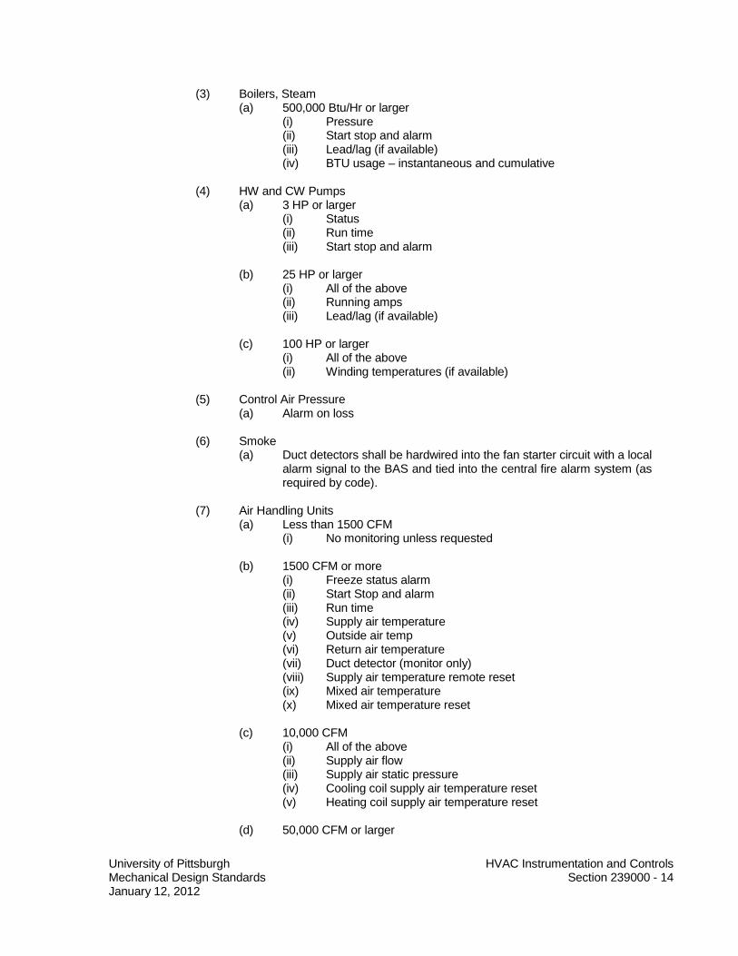
University of Pittsburgh HVAC Instrumentation and Controls Mechanical Design Standards Section 239000 - 14 January 12, 2012
(3) Boilers, Steam (a) 500,000 Btu/Hr or larger
(i) Pressure (ii) Start stop and alarm (iii) Lead/lag (if available) (iv) BTU usage – instantaneous and cumulative
(4) HW and CW Pumps
(a) 3 HP or larger (i) Status (ii) Run time (iii) Start stop and alarm
(b) 25 HP or larger (i) All of the above (ii) Running amps (iii) Lead/lag (if available)
(c) 100 HP or larger (i) All of the above (ii) Winding temperatures (if available)
(5) Control Air Pressure (a) Alarm on loss
(6) Smoke
(a) Duct detectors shall be hardwired into the fan starter circuit with a local alarm signal to the BAS and tied into the central fire alarm system (as required by code).
(7) Air Handling Units
(a) Less than 1500 CFM (i) No monitoring unless requested
(b) 1500 CFM or more (i) Freeze status alarm (ii) Start Stop and alarm (iii) Run time (iv) Supply air temperature (v) Outside air temp (vi) Return air temperature (vii) Duct detector (monitor only) (viii) Supply air temperature remote reset (ix) Mixed air temperature (x) Mixed air temperature reset
(c) 10,000 CFM
(i) All of the above (ii) Supply air flow (iii) Supply air static pressure (iv) Cooling coil supply air temperature reset (v) Heating coil supply air temperature reset
(d) 50,000 CFM or larger

University of Pittsburgh HVAC Instrumentation and Controls Mechanical Design Standards Section 239000 - 15 January 12, 2012
(i) All of the above (ii) Running amps
(8) Fume Hoods
(a) Face velocity (b) CFM (c) Sash position (d) Hood usage sensor (e) Alarms (f) Any other parameters deemed necessary by the Senior Mechanical
Engineer
(9) Environmental Rooms (a) Rooms temperatures (b) CFM (supply and exhaust) (c) Pressurization (d) Alarms (e) Any other parameters deemed necessary by the Senior Mechanical
Engineer
(10) Steam metering – see section on Steam metering (11) Chilled water metering – see section on Chilled water metering
(12) Variable volume box
(a) Damper position (b) Temperature (c) CFM (d) Any other parameters deemed necessary by the Senior Mechanical
Engineer 16. Alarms - The following Alarms shall be generated where applicable
(a) Air Handling Units (1) Supply Fan Failure (2) Return Fan Failure (3) Mixed Air Low Limit (4) Freeze (5) Smoke (6) Filter (7) High Discharge Static Pressure (8) High Discharge Air Temperature (9) Low Discharge Air Temperature (10) VFD Fault
(b) Chillers (1) Low chilled water temperature (2) Low evaporator temperature or pressure (3) High condenser refrigerant pressure (4) Evaporator water flow failure (5) Condenser water flow failure (6) Low oil pressure (7) Low oil temperature (8) High oil temperature (9) High motor winding temperatures (10) Sensor faults

University of Pittsburgh HVAC Instrumentation and Controls Mechanical Design Standards Section 239000 - 16 January 12, 2012
(11) Proper operation of unit controls
END OF SECTION