Division 8 CADD Standards and Procedures · utilized in preparing details it is not necessary to...
104
WSF Terminal Design Manual M 3082.05 Page 800-1 April 2016 Division 8 CADD Standards and Procedures 801 Introduction 802 WSF CADD Software 803 MicroStation Resource and Support Files 804 Project Naming 805 Directory Structure 806 File Names 807 Plan Sequence 808 Drawing List 809 Drafting Standards 810 Plan Submittals 811 Environmental Permit Standards 812 General Plan Sheets 813 Civil Plan Sheet Series 814 Structural Plan Sheet Series 815 Fluid Power Hydraulic Plan Sheet Series 816 Electrical Design Drawing Series 817 Mechanical Design Drawing Series
Transcript of Division 8 CADD Standards and Procedures · utilized in preparing details it is not necessary to...
WSF Terminal Design Manual M 3082.05 Page 800-1 April 2016
Division 8 CADD Standards and Procedures
801 Introduction802 WSF CADD Software803 MicroStation Resource and Support Files804 Project Naming805 Directory Structure 806 File Names807 Plan Sequence 808 Drawing List809 Drafting Standards810 Plan Submittals811 Environmental Permit Standards812 General Plan Sheets813 Civil Plan Sheet Series814 Structural Plan Sheet Series815 Fluid Power Hydraulic Plan Sheet Series816 Electrical Design Drawing Series817 Mechanical Design Drawing Series
CADD Standards and Procedures Division 8
Page 800-2 WSF Terminal Design Manual M 3082.05 April 2016
801 Introduction
801.01 Purpose and ScopeDivision 800 provides instruction and guidance for the preparation of contract drawings using Bentley’s MicroStation© Computer-Aided Design and Drafting (CADD or CAD) software on all Washington State Ferries (WSF) projects. WSF is a division of the Washington State Department of Transportation (WSDOT), which uses the Plans Preparation Manual M 22-31 as a guideline for preparing PS&E documents. However, the Plans Preparation Manual applies primarily to roadway-type projects and does not adequately address the specific needs and variety of projects performed by WSF. The purpose of Division 800 is to supplement the WSDOT Plans Preparation Manual to meet WSF CADD requirements. The WSF CADD Standards and Procedures specified in Division 800 shall supplement those in the WSDOT Plans Preparation Manual.
Special exceptions to the use of MicroStation are those projects that include within their scope the construction of shore side buildings. Washington State Ferries depends on the WSDOT Facilities Branch or Consultants to provide the building design services necessary to complete that portion of the contract. In projects that incorporate items of work other than architecture there will be a “design limit” of 5 feet beyond the perimeter of the architectural work that will mark the boundary where the architectural and other discipline work will coincide.
801.02 Procedure for Revisions and Updates(a) ProjectSpecificCADDStandards
As with everything there are exceptions to the rules. The format for the PS&E CADD documents may be changed slightly by the Project Manager for WSF. In order to accommodate changes, the proposed variations to the CADD Manual shall be forwarded to the WSF CADD Coordinator for review and approval.
Changes can be made to text properties, line styles, level symbology and element attributes. There will, however, be no changes allowed in the layout of the WSF sheet borders.
Division 8 CADD Standards and Procedures
WSF Terminal Design Manual M 3082.05 Page 800-3 April 2016
802 WSF CADD Software
802.01 GeneralWSF only supports MicroStation© (Bentley Systems, Inc.) electronic CADD files. The importance of organization and consistency cannot be overemphasized as the electronic files prepared by consultants are frequently used as a basis for continued work or modifications. Electronic organization quality is equally important as the plotted deliverables.
All work submittals and deliverables must be created and developed in MicroStation© format and conform to Division 800, the Washington State Department of Transportation (WSDOT) Plans Preparation Manual (PPM), and the WSDOT Bridge Design Manual LRFD (BDM) (for Structures related issues). Structural work will be completed in accordance with Chapter 11 of the BDM as it pertains to detailing.
Any inconsistencies—electronic, aesthetic, or otherwise—with the previously noted manuals are the sole responsibility of the originators of the drawings to correct.
On any WSF project done by a consultant team, the prime consultant is responsible for insuring the CADD files are submitted in a “usable” MicroStation format.
All Computer-Aided Engineering (CAE) by the Washington State Ferries and its consultants must conform to the WSF CSPM, the WSDOT PPM, and in part, the WSDOT BDM. Any inconsistencies—electronic, aesthetic, or otherwise—with the WSF CSPM, WSDOT PPM, or the WSDOT BDM are the sole responsibility of the originators of the drawings to resolve. InRoads© is the standard CAE package and AutoTurn© is the standard turn radius analyzing software of WSDOT and WSF.
For all “in house” work the MicroStation© files will be accessed through the use of the desktop icon for MicroStation©. All work will be done in the Expanded Levels environment.
802.02 File Sharing/DeliveryWSF will accept files transported to it in the following formats:• CD or DVD.• Posting to the Consultant’s ftp site and made available to WSF for downloading.• Uploading to the WSDOT ftp site at ftp://ftp.wsdot.wa.gov/ and placed in a
location made accessible for public or Consultant use.• Uploading to the WSDOT secured ftp site. This requires the use of software that
will accommodate the input of information that is required for access to these types of sites. The program recommended by WSDOT is FileZilla©. Access information can be obtained from the Project Manager.
All files must be in a format specified in this CADD Manual and be useable by MicroStation© without conversion.
CADD Standards and Procedures Division 8
Page 800-4 WSF Terminal Design Manual M 3082.05 April 2016
803 MicroStation Resource and Support Files
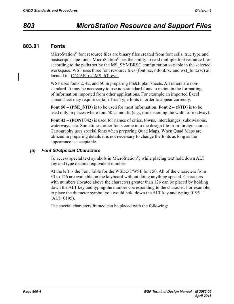
803.01 FontsMicroStation© font resource files are binary files created from font cells, true type and postscript shape fonts. MicroStation© has the ability to read multiple font resource files according to the paths set by the MS_SYMBRSC configuration variable in the selected workspace. WSF uses three font resource files (font.rsc, ntfont.rsc and wsf_font.rsc) all located in: C:\CAE_rsc\MS_63Level
WSF uses fonts 2, 42, and 50 in preparing PS&E plan sheets. All others are non-standard. It may be necessary to use non-standard fonts to maintain the formatting of information imported from other applications. For example an imported Excel spreadsheet may require certain True Type fonts in order to appear correctly.
Font 50 – (PSE_STD) is to be used for most information. Font 2 – (STD) is to be used only in places where font 50 cannot fit (e.g., dimensioning the width of roadway).
Font 42 – (FONT042) is used for names of cities, towns, interchanges, subdivisions, waterways, etc. Sometimes, other fonts come into the design file from foreign sources. Cartography uses special fonts when preparing Quad Maps. When Quad Maps are utilized in preparing details it is not necessary to change the fonts as long as the appearance is acceptable.
(a) Font 50/Special CharactersTo access special text symbols in MicroStation©, while placing text hold down ALT key and type decimal equivalent number.
At the left is the Font Table for the WSDOT/WSF font 50. All of the characters from 33 to 126 are available on the keyboard without doing anything special. Characters with numbers (located above the character) greater than 126 can be placed by holding down the ALT key and typing the number corresponding to the character. For example, to place the diameter symbol you would hold down the ALT key and typing 0195 (ALT+0195).
The special characters framed can be placed with the following:
Division 8 CADD Standards and Procedures
WSF Terminal Design Manual M 3082.05 Page 800-5 April 2016
CADD Standards and Procedures Division 800
Page 800-3-4 Terminal Design Manual M 3082March 2014
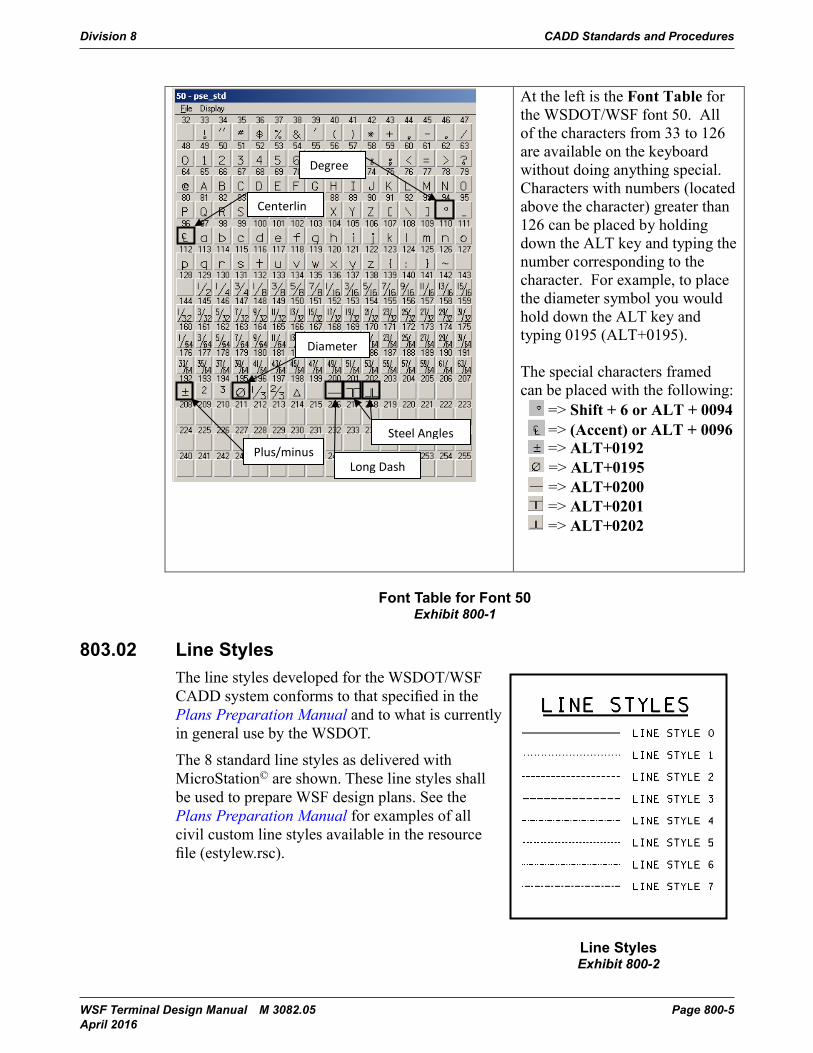
At the left is the Font Table for the WSDOT/WSF font 50. All of the characters from 33 to 126 are available on the keyboardwithout doing anything special. Characters with numbers (located above the character) greater than 126 can be placed by holding down the ALT key and typing the number corresponding to the character. For example, to place the diameter symbol you would hold down the ALT key and typing 0195 (ALT+0195).
The special characters framed can be placed with the following:
=> Shift + 6 or ALT + 0094=> (Accent) or ALT + 0096=> ALT+0192=> ALT+0195 => ALT+0200=> ALT+0201=> ALT+0202
Exhibit 800-1: Font Table for Font 50
803.02 Line StylesThe line styles developed for the WSDOT/WSF CADD system conforms to that specified in the Plans Preparation Manual and to what is currently in general use by the WSDOT.
The 8 standard line styles as delivered with MicroStation© are shown. These line styles shall be used to prepare WSF design plans. See the Plans Preparation Manual for examples of all civil custom line styles available in the resource file (estylew.rsc).
Plus/minus
Diameter
Centerlin
Degree
Long Dash
Steel Angles
Font Table for Font 50Exhibit 800-1
803.02 Line StylesThe line styles developed for the WSDOT/WSF
CADD Standards and Procedures Division 800
Terminal Design Manual M 3082 Page 800-3-5March 2014
Exhibit 800-2: Line Styles
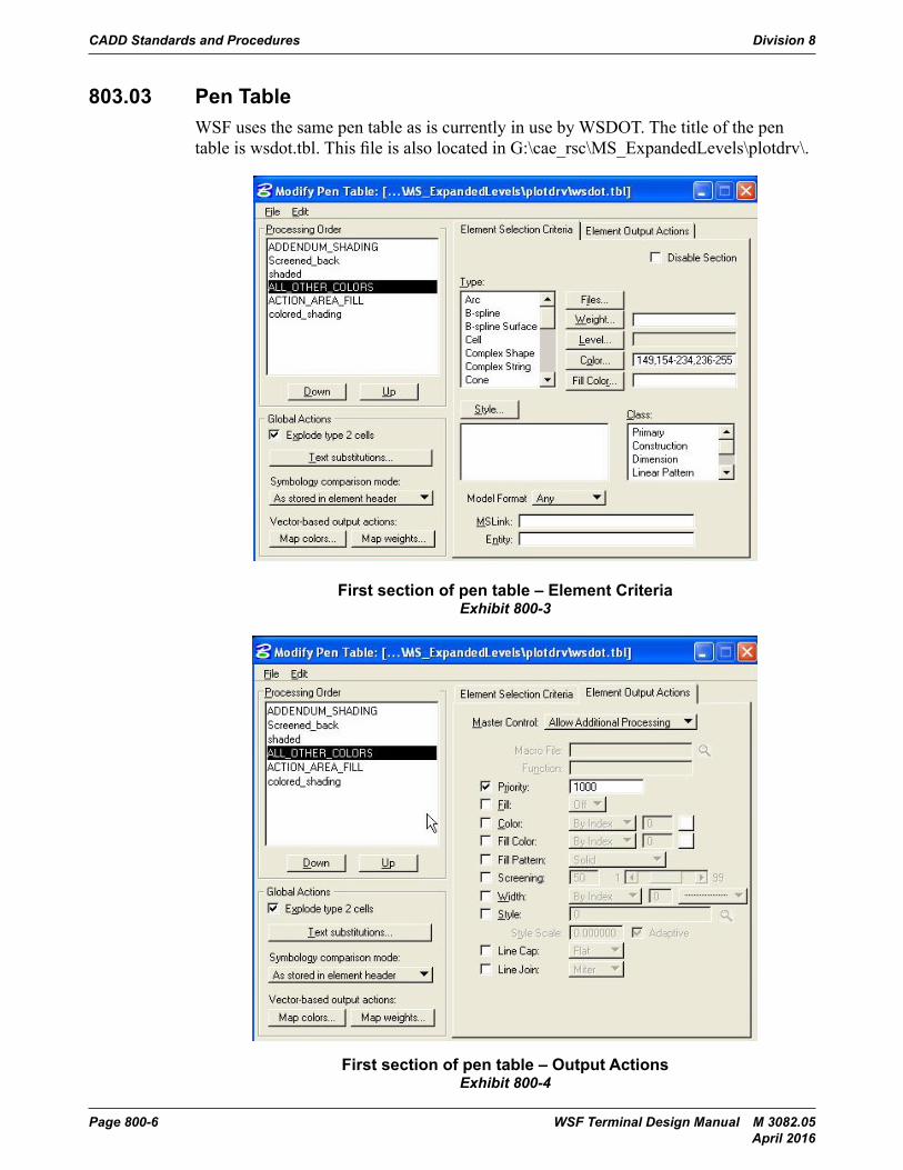
803.03 Pen TableWSF uses the same pen table as is currently in use by WSDOT. The title of the pen table is wsdot.tbl. This file is also located in G:\cae_rsc\MS_ExpandedLevels\plotdrv\.
Exhibit 800-3: First section of pen table – Element Criteria
Line StylesExhibit 800-2
CADD system conforms to that specified in the Plans Preparation Manual and to what is currently in general use by the WSDOT.
The 8 standard line styles as delivered with MicroStation© are shown. These line styles shall be used to prepare WSF design plans. See the Plans Preparation Manual for examples of all civil custom line styles available in the resource file (estylew.rsc).
CADD Standards and Procedures Division 8
Page 800-6 WSF Terminal Design Manual M 3082.05 April 2016
803.03 Pen TableWSF uses the same pen table as is currently in use by WSDOT. The title of the pen table is wsdot.tbl. This file is also located in G:\cae_rsc\MS_ExpandedLevels\plotdrv\.
CADD Standards and Procedures Division 800
Terminal Design Manual M 3082 Page 800-3-5March 2014
Exhibit 800-2: Line Styles
803.03 Pen TableWSF uses the same pen table as is currently in use by WSDOT. The title of the pen table is wsdot.tbl. This file is also located in G:\cae_rsc\MS_ExpandedLevels\plotdrv\.
Exhibit 800-3: First section of pen table – Element CriteriaFirst section of pen table – Element CriteriaExhibit 800-3
CADD Standards and Procedures Division 800
Page 800-3-6 Terminal Design Manual M 3082March 2014
Exhibit 800-4: First section of pen table – Output Actions
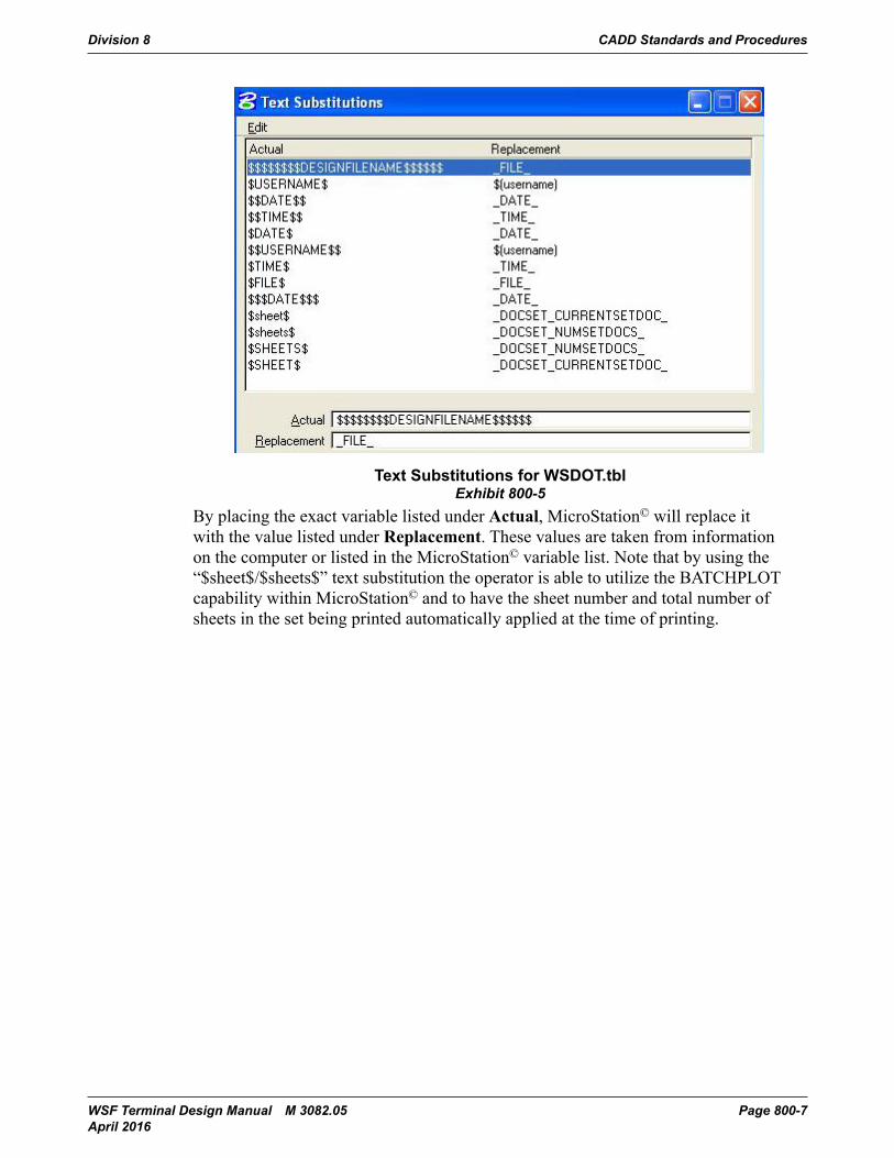
Exhibit 800-5: Text Substitutions for WSDOT.tbl
First section of pen table – Output ActionsExhibit 800-4
Division 8 CADD Standards and Procedures
WSF Terminal Design Manual M 3082.05 Page 800-7 April 2016
CADD Standards and Procedures Division 800
Page 800-3-6 Terminal Design Manual M 3082March 2014
Exhibit 800-4: First section of pen table – Output Actions
Exhibit 800-5: Text Substitutions for WSDOT.tblText Substitutions for WSDOT.tblExhibit 800-5
By placing the exact variable listed under Actual, MicroStation© will replace it with the value listed under Replacement. These values are taken from information on the computer or listed in the MicroStation© variable list. Note that by using the “$sheet$/$sheets$” text substitution the operator is able to utilize the BATCHPLOT capability within MicroStation© and to have the sheet number and total number of sheets in the set being printed automatically applied at the time of printing.
CADD Standards and Procedures Division 8
Page 800-8 WSF Terminal Design Manual M 3082.05 April 2016
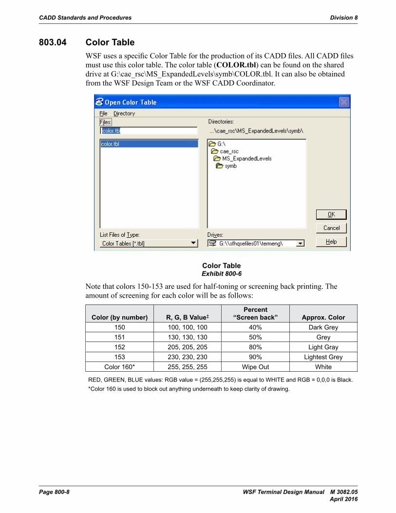
803.04 Color TableWSF uses a specific Color Table for the production of its CADD files. All CADD files must use this color table. The color table (COLOR.tbl) can be found on the shared drive at G:\cae_rsc\MS_ExpandedLevels\symb\COLOR.tbl. It can also be obtained from the WSF Design Team or the WSF CADD Coordinator.
CADD Standards and Procedures Division 800
Terminal Design Manual M 3082 Page 800-3-7March 2014
By placing the exact variable listed under Actual, MicroStation© will replace it with the value listed under Replacement. These values are taken from information on the computer or listed in the MicroStation© variable list. Note that by using the “$sheet$/$sheets$” text substitution the operator is able to utilize the BATCHPLOT capability within MicroStation© and to have the sheet number and total number of sheets in the set being printed automatically applied at the time of printing.
803.04 Color TableWSF uses a specific Color Table for the production of its CADD files. All CADD files must use this color table. The color table (COLOR.tbl) can be found on the shared drive at G:\cae_rsc\MS_ExpandedLevels\symb\COLOR.tbl. It can also be obtained from the WSF Design Team or the WSF CADD Coordinator.
Exhibit 800-6: Color Table
Note that colors 150-153 are used for half-toning or screening back printing. The amount of screening for each color will be as follows:
Color (by number) R, G, B Value ‡ Percent “Screen back” Approx. Color
150 100, 100, 100 40% Dark Grey
151 130, 130, 130 50% Grey
152 205, 205, 205 80% Light Gray
Color TableExhibit 800-6
Note that colors 150-153 are used for half-toning or screening back printing. The amount of screening for each color will be as follows:
Color (by number) R, G, B Value‡Percent
“Screen back” Approx. Color150 100, 100, 100 40% Dark Grey151 130, 130, 130 50% Grey152 205, 205, 205 80% Light Gray153 230, 230, 230 90% Lightest Grey
Color 160* 255, 255, 255 Wipe Out White
RED, GREEN, BLUE values: RGB value = (255,255,255) is equal to WHITE and RGB = 0,0,0 is Black.*Color 160 is used to block out anything underneath to keep clarity of drawing.
Division 8 CADD Standards and Procedures
WSF Terminal Design Manual M 3082.05 Page 800-9 April 2016
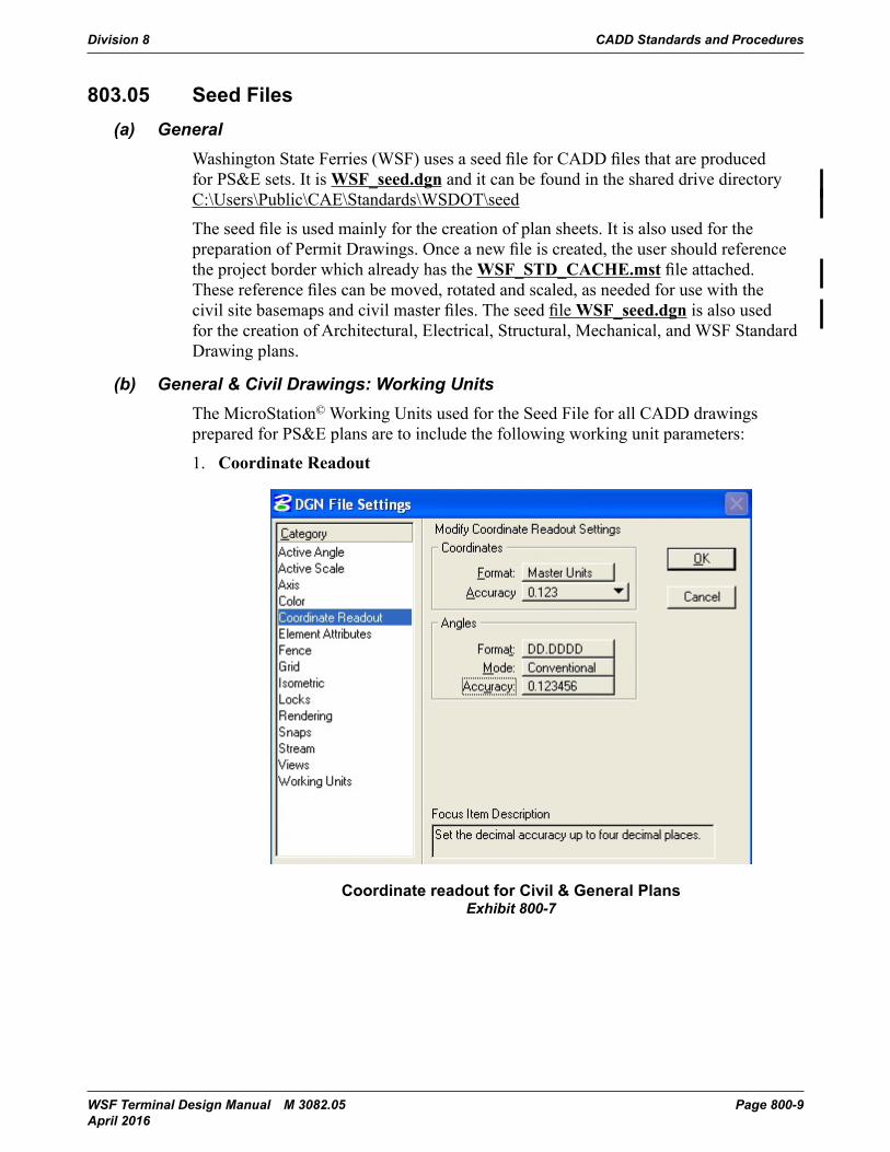
803.05 Seed Files(a) General
Washington State Ferries (WSF) uses a seed file for CADD files that are produced for PS&E sets. It is WSF_seed.dgn and it can be found in the shared drive directory C:\Users\Public\CAE\Standards\WSDOT\seed
The seed file is used mainly for the creation of plan sheets. It is also used for the preparation of Permit Drawings. Once a new file is created, the user should reference the project border which already has the WSF_STD_CACHE.mst file attached. These reference files can be moved, rotated and scaled, as needed for use with the civil site basemaps and civil master files. The seed file WSF_seed.dgn is also used for the creation of Architectural, Electrical, Structural, Mechanical, and WSF Standard Drawing plans.
(b) General & Civil Drawings: Working UnitsThe MicroStation© Working Units used for the Seed File for all CADD drawings prepared for PS&E plans are to include the following working unit parameters:
1. Coordinate Readout
CADD Standards and Procedures Division 800
Terminal Design Manual M 3082 Page 800-3-9March 2014
1. Coordinate Readout
Exhibit 800-7: Coordinate readout for Civil & General Plans
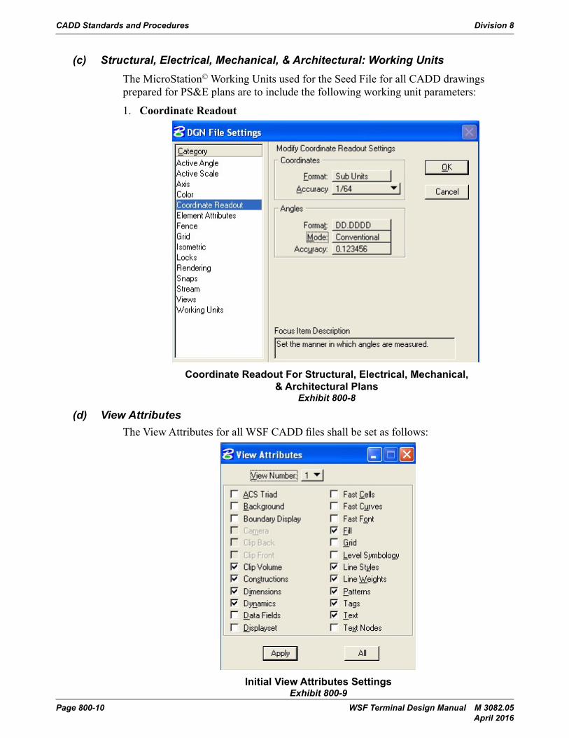
(c) Structural, Electrical, Mechanical, & Architectural: Working UnitsThe MicroStation© Working Units used for the Seed File for all CADD drawings prepared for PS&E plans are to include the following working unit parameters:
Coordinate readout for Civil & General PlansExhibit 800-7
CADD Standards and Procedures Division 8
Page 800-10 WSF Terminal Design Manual M 3082.05 April 2016
(c) Structural, Electrical, Mechanical, & Architectural: Working UnitsThe MicroStation© Working Units used for the Seed File for all CADD drawings prepared for PS&E plans are to include the following working unit parameters:
1. Coordinate Readout
CADD Standards and Procedures Division 800
Page 800-3-10 Terminal Design Manual M 3082March 2014
1. Coordinate Readout
Exhibit 800-8: Coordinate readout for Structural, Electrical, Mechanical, & Architectural Plans
(d) View AttributesThe View Attributes for all WSF CADD files shall be set as follows:
Exhibit 800-9: Initial View Attributes Settings
Coordinate Readout For Structural, Electrical, Mechanical, & Architectural Plans
Exhibit 800-8
(d) View AttributesThe View Attributes for all WSF CADD files shall be set as follows:
CADD Standards and Procedures Division 800
Page 800-3-10 Terminal Design Manual M 3082March 2014
1. Coordinate Readout
Exhibit 800-8: Coordinate readout for Structural, Electrical, Mechanical, & Architectural Plans
(d) View AttributesThe View Attributes for all WSF CADD files shall be set as follows:
Exhibit 800-9: Initial View Attributes SettingsInitial View Attributes SettingsExhibit 800-9
Division 8 CADD Standards and Procedures
WSF Terminal Design Manual M 3082.05 Page 800-11 April 2016
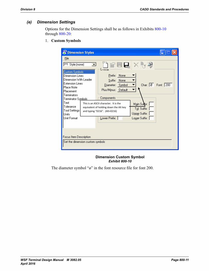
(e) Dimension SettingsOptions for the Dimension Settings shall be as follows in Exhibits 800-10 through 800-20:
1. Custom Symbols
CADD Standards and Procedures Division 800
Terminal Design Manual M 3082 Page 800-3-11March 2014
(e) Dimension SettingsOptions for the Dimension Settings shall be as follows in Exhibit 800-10 through 800-20:
1. Custom Symbols
Exhibit 800-10: Dimension Custom Symbol
The diameter symbol “ø” in the font resource file for font 200.
This is an ASCII character. It is the equivalent of holding down the Alt key and typing “0216”. (Alt+0216)
Dimension Custom SymbolExhibit 800-10
The diameter symbol “ø” in the font resource file for font 200.
CADD Standards and Procedures Division 8
Page 800-12 WSF Terminal Design Manual M 3082.05 April 2016
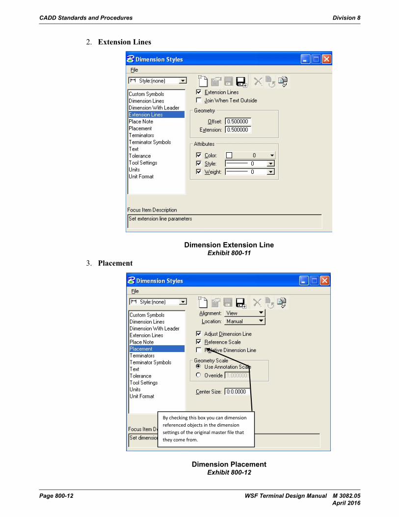
2. Extension Lines
CADD Standards and Procedures Division 800
Page 800-3-12 Terminal Design Manual M 3082March 2014
2. Extension Lines
Exhibit 800-11: Dimension Extension Line
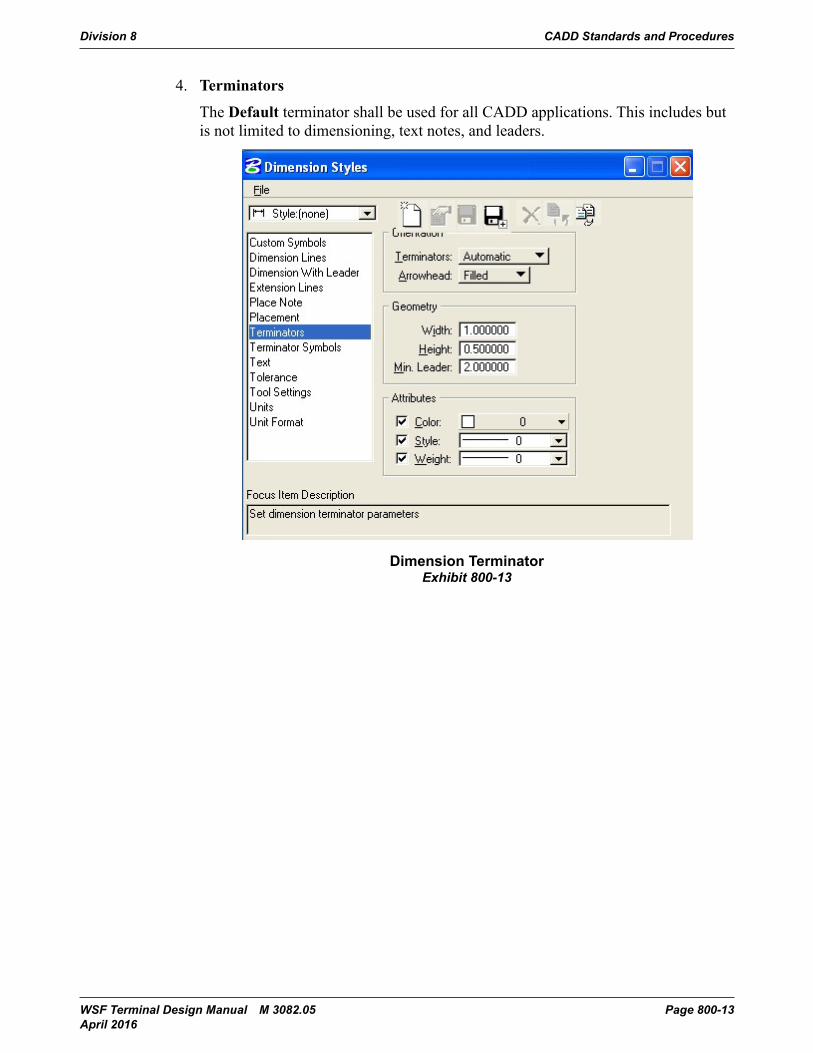
3. Placement
Exhibit 800-12: Dimension Placement
By checking this box you can dimension referenced objects in the dimension settings of the original master file that they come from.
Dimension Extension LineExhibit 800-11
3. Placement
CADD Standards and Procedures Division 800
Page 800-3-12 Terminal Design Manual M 3082March 2014
2. Extension Lines
Exhibit 800-11: Dimension Extension Line
3. Placement
Exhibit 800-12: Dimension Placement
By checking this box you can dimension referenced objects in the dimension settings of the original master file that they come from.
Dimension PlacementExhibit 800-12
Division 8 CADD Standards and Procedures
WSF Terminal Design Manual M 3082.05 Page 800-13 April 2016
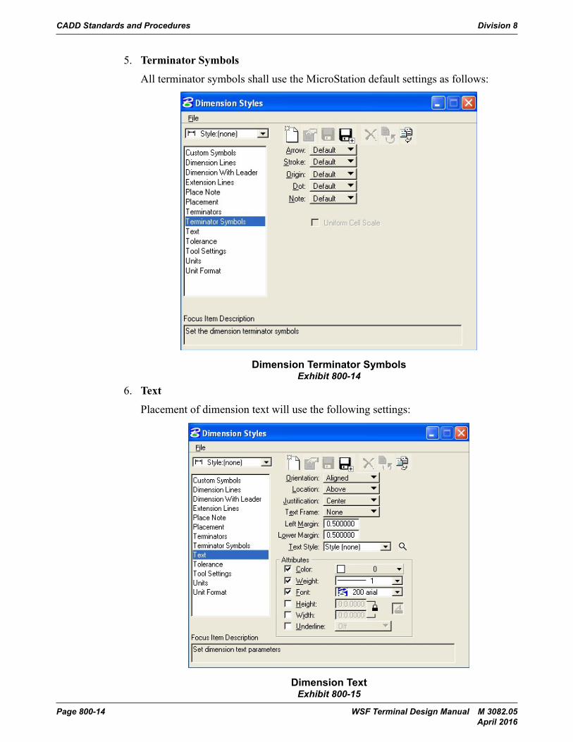
4. Terminators
The Default terminator shall be used for all CADD applications. This includes but is not limited to dimensioning, text notes, and leaders.
CADD Standards and Procedures Division 800
Terminal Design Manual M 3082 Page 800-3-13March 2014
4. TerminatorsThe Default terminator shall be used for all CADD applications. This includes but is not limited to dimensioning, text notes, and leaders.
Exhibit 800-13: Dimension TerminatorDimension Terminator
Exhibit 800-13
CADD Standards and Procedures Division 8
Page 800-14 WSF Terminal Design Manual M 3082.05 April 2016
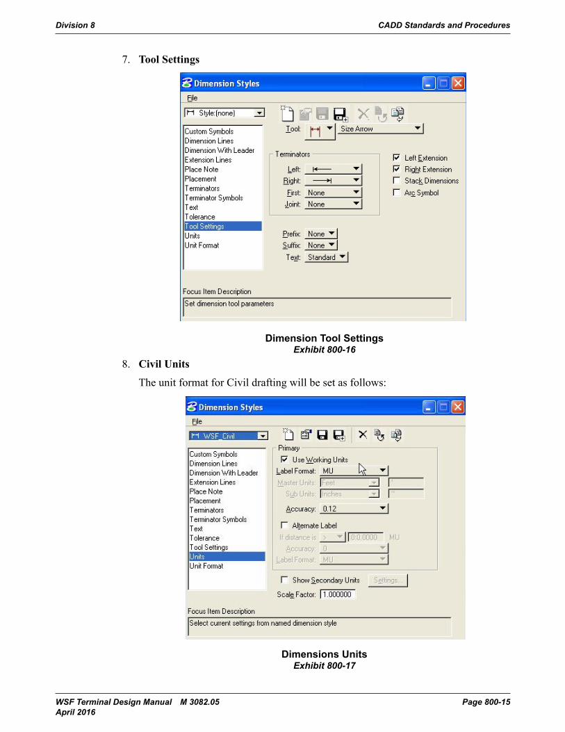
5. Terminator Symbols
All terminator symbols shall use the MicroStation default settings as follows:
CADD Standards and Procedures Division 800
Page 800-3-14 Terminal Design Manual M 3082March 2014
5. Terminator SymbolsAll terminator symbols shall use the MicroStation default settings as follows:
Exhibit 800-14: Dimension Terminator Symbols
6. TextPlacement of dimension text will use the following settings:
Dimension Terminator SymbolsExhibit 800-14
6. Text
Placement of dimension text will use the following settings:
CADD Standards and Procedures Division 800
Page 800-3-14 Terminal Design Manual M 3082March 2014
5. Terminator SymbolsAll terminator symbols shall use the MicroStation default settings as follows:
Exhibit 800-14: Dimension Terminator Symbols
6. TextPlacement of dimension text will use the following settings:
Dimension TextExhibit 800-15
Division 8 CADD Standards and Procedures
WSF Terminal Design Manual M 3082.05 Page 800-15 April 2016
7. Tool Settings
CADD Standards and Procedures Division 800
Terminal Design Manual M 3082 Page 800-3-9March 2014
7. Tool Settings
Exhibit 800-16: Dimension Tool Settings
8. Civil UnitsThe unit format for Civil drafting will be set as follows:
Dimension Tool SettingsExhibit 800-16
8. Civil Units
The unit format for Civil drafting will be set as follows:
CADD Standards and Procedures Division 800
Page 800-3-10 Terminal Design Manual M 3082March 2014
Exhibit 800-17: Dimensions Units
9. Structural, Mechanical, Electrical, and Architectural UnitsThe unit format for Structural, Mechanical, Electrical, and Architectural drafting will be set as follows:
Dimensions UnitsExhibit 800-17
CADD Standards and Procedures Division 8
Page 800-16 WSF Terminal Design Manual M 3082.05 April 2016
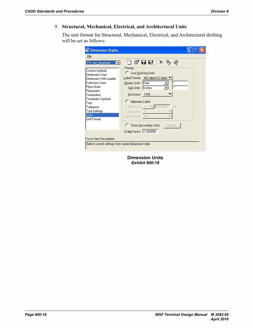
9. Structural, Mechanical, Electrical, and Architectural Units
The unit format for Structural, Mechanical, Electrical, and Architectural drafting will be set as follows:
CADD Standards and Procedures Division 800
Terminal Design Manual M 3082 Page 800-3-17March 2014
Exhibit 800-17: Dimensions Units
9. Structural, Mechanical, Electrical, and Architectural UnitsThe unit format for Structural, Mechanical, Electrical, and Architectural drafting will be set as follows:
Exhibit 800-18: Dimension Units
10. Unit FormatThe unit format for the seed file shall be set as follows for angular measurement and length measurement:
Dimension UnitsExhibit 800-18
Division 8 CADD Standards and Procedures
WSF Terminal Design Manual M 3082.05 Page 800-17 April 2016
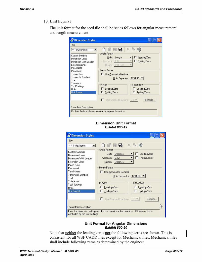
10. Unit Format
The unit format for the seed file shall be set as follows for angular measurement and length measurement:
CADD Standards and Procedures Division 800
Page 800-3-18 Terminal Design Manual M 3082March 2014
Exhibit 800-19: Dimension Unit Format
Exhibit 800-20: Unit Format for Angular Dimensions
Note that neither the leading zeros nor the following zeros are shown. This is consistent for all WSF CADD files except for Mechanical files. Mechanical files shall include following zeros as determined by the engineer.
Dimension Unit FormatExhibit 800-19
CADD Standards and Procedures Division 800
Page 800-3-18 Terminal Design Manual M 3082March 2014
Exhibit 800-19: Dimension Unit Format
Exhibit 800-20: Unit Format for Angular Dimensions
Note that neither the leading zeros nor the following zeros are shown. This is consistent for all WSF CADD files except for Mechanical files. Mechanical files shall include following zeros as determined by the engineer.
Unit Format for Angular DimensionsExhibit 800-20
Note that neither the leading zeros nor the following zeros are shown. This is consistent for all WSF CADD files except for Mechanical files. Mechanical files shall include following zeros as determined by the engineer.
CADD Standards and Procedures Division 8
Page 800-18 WSF Terminal Design Manual M 3082.05 April 2016
804 Project Naming
804.01 Project Naming Convention
CADD Standards and Procedures Division 800
Terminal Design Manual M 3082 Page 800-4-9March 2014
804 Project Naming
804.01 Project Naming Convention
09 X 05 3
Where,
09 = the year that the project design was begunX = Maintenance or W = Capital Funding05 = Terminal Code (Edmonds Ferry Terminal is shown) 3 = Third design project begun for the Edmonds terminal in design year
Terminal codes:
Anacortes = 01 Mukilteo = 12
Bainbridge = 02 Orcas = 13
Bremerton = 03 Point Defiance = 14
Clinton = 04 Port Townsend = 15
Edmonds = 05 Seattle = 16
Eagle Harbor = 06 Shaw = 17
Fauntleroy = 07 Sidney = 18
Friday Harbor = 08 Southworth = 19
Coupeville* = 09 System Wide = 20
Kingston = 10 Tahlequah = 21
Lopez = 11 Vashon = 22
* Formerly Keystone
1. The project “name” or “number is generated by the Project Manager when they fill out the information in the “Cradle to Grave project number” file. The file can be found at: G:\Admin\C2G_Proj_Numbers\Project_Numbers.xls. The number will appear in the Terminal directory on the “G” drive with either the Work Order number or the contract number following it. The number accompanying the project number will indicate what
Design Year
Funding
Source
Terminal
Code
Project Number
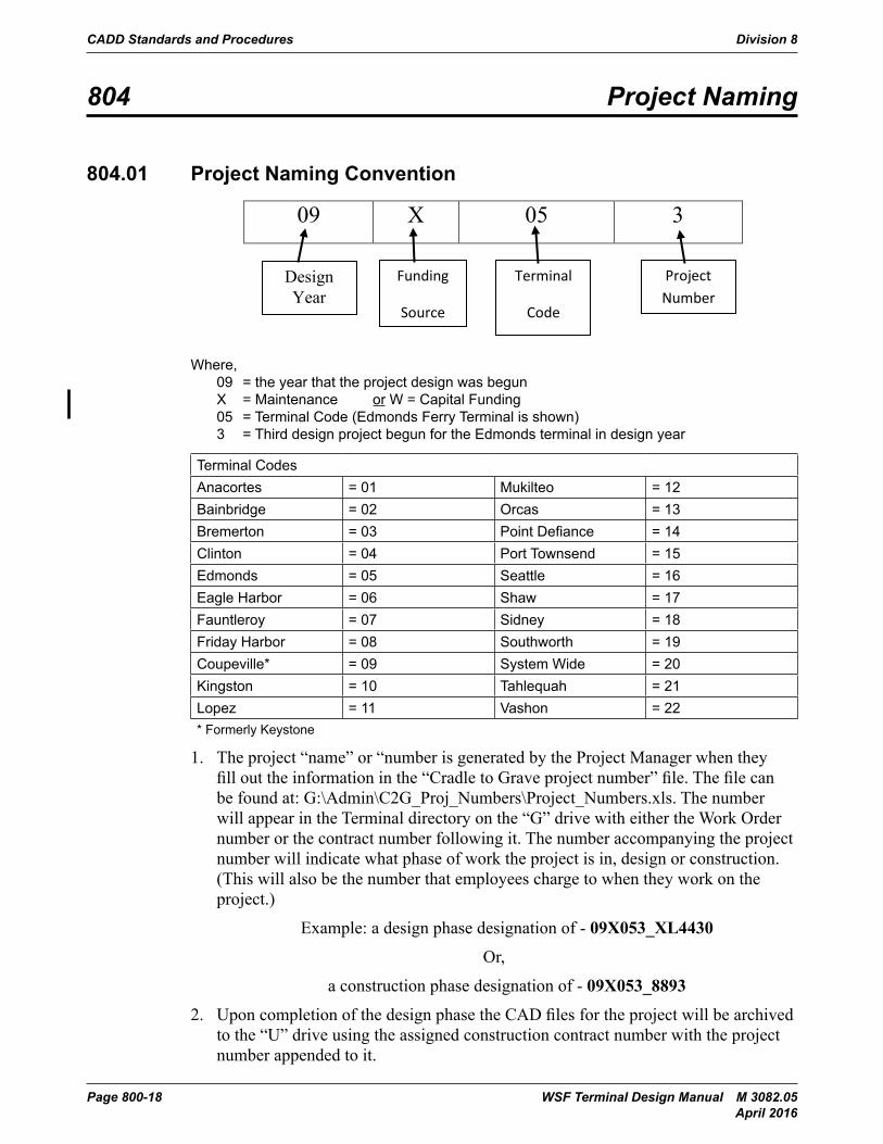
Where, 09 = the year that the project design was begun X = Maintenance or W = Capital Funding 05 = Terminal Code (Edmonds Ferry Terminal is shown) 3 = Third design project begun for the Edmonds terminal in design year
Terminal CodesAnacortes = 01 Mukilteo = 12Bainbridge = 02 Orcas = 13Bremerton = 03 Point Defiance = 14Clinton = 04 Port Townsend = 15Edmonds = 05 Seattle = 16Eagle Harbor = 06 Shaw = 17Fauntleroy = 07 Sidney = 18Friday Harbor = 08 Southworth = 19Coupeville* = 09 System Wide = 20Kingston = 10 Tahlequah = 21Lopez = 11 Vashon = 22* Formerly Keystone
1. The project “name” or “number is generated by the Project Manager when they fill out the information in the “Cradle to Grave project number” file. The file can be found at: G:\Admin\C2G_Proj_Numbers\Project_Numbers.xls. The number will appear in the Terminal directory on the “G” drive with either the Work Order number or the contract number following it. The number accompanying the project number will indicate what phase of work the project is in, design or construction. (This will also be the number that employees charge to when they work on the project.)
Example: a design phase designation of - 09X053_XL4430
Or,
a construction phase designation of - 09X053_8893
2. Upon completion of the design phase the CAD files for the project will be archived to the “U” drive using the assigned construction contract number with the project number appended to it.
Division 8 CADD Standards and Procedures
WSF Terminal Design Manual M 3082.05 Page 800-19 April 2016
805 Directory Structure
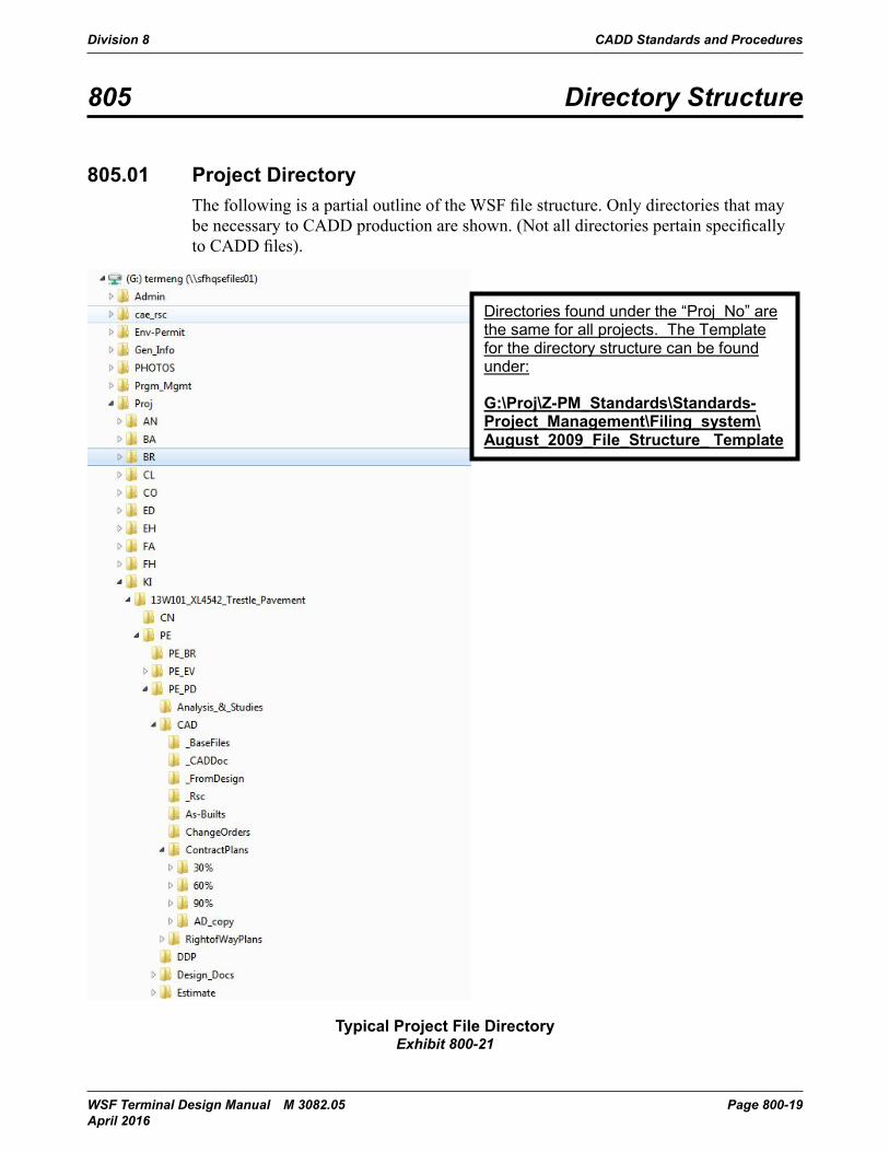
805.01 Project DirectoryThe following is a partial outline of the WSF file structure. Only directories that may be necessary to CADD production are shown. (Not all directories pertain specifically to CADD files).
CADD Standards and Procedures Division 800
Terminal Design Manual M 3082 Page 800-5-21March 2014
805 Directory Structure
805.01 Project DirectoryThe following is a partial outline of the WSF file structure. Only directories that may be necessary to CADD production are shown. (Not all directories pertain specifically to CADD files).
Exhibit 800-21: Typical Project File Directory
Directories found under the “Proj_No” are the same for all projects. The Template for the directory structure can be found under:
G:\Proj\Z-PM_Standards\Standards-Project_Management\Filing_system\August_2009_File_Structure_ Template
Typical Project File DirectoryExhibit 800-21
CADD Standards and Procedures Division 8
Page 800-20 WSF Terminal Design Manual M 3082.05 April 2016
806 File Names
806.01 File Extensions(a) Master Files and Basemaps (.mst)
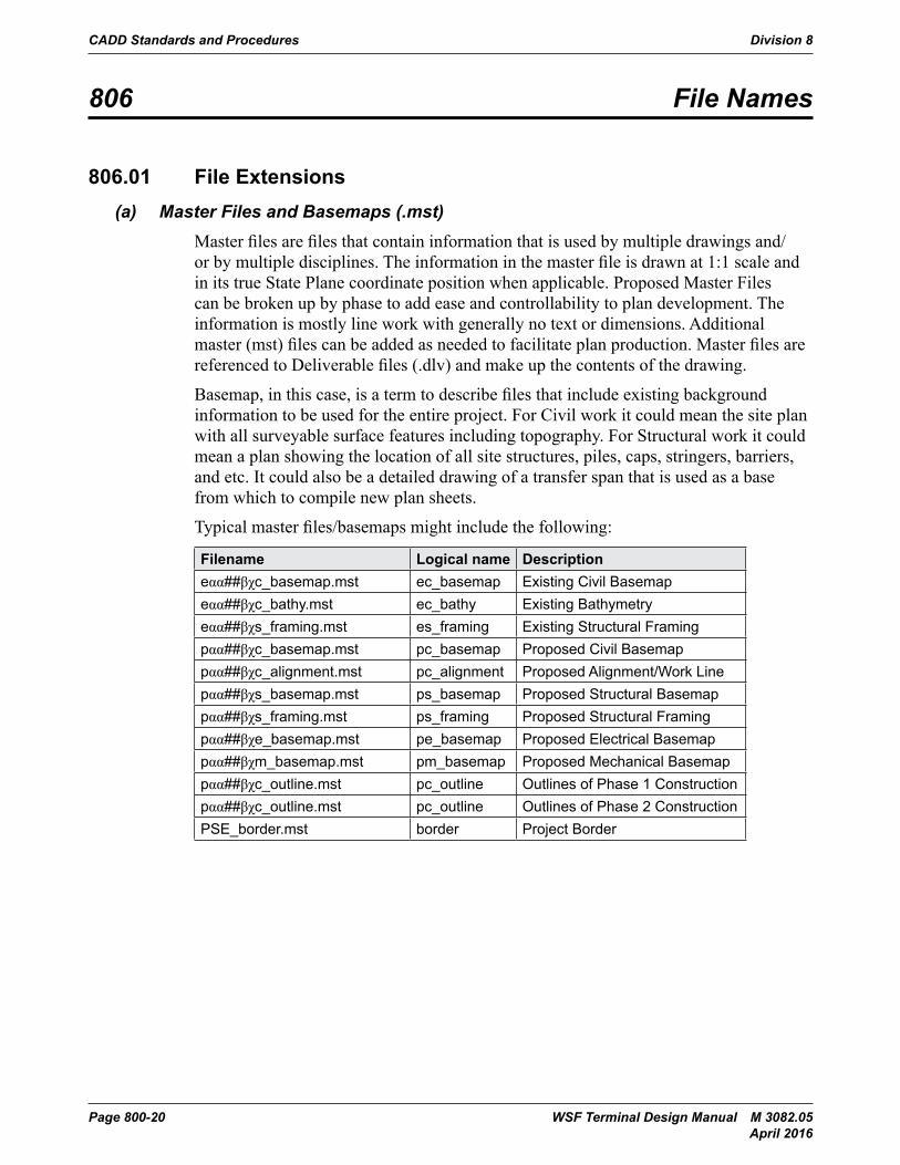
Master files are files that contain information that is used by multiple drawings and/or by multiple disciplines. The information in the master file is drawn at 1:1 scale and in its true State Plane coordinate position when applicable. Proposed Master Files can be broken up by phase to add ease and controllability to plan development. The information is mostly line work with generally no text or dimensions. Additional master (mst) files can be added as needed to facilitate plan production. Master files are referenced to Deliverable files (.dlv) and make up the contents of the drawing.
Basemap, in this case, is a term to describe files that include existing background information to be used for the entire project. For Civil work it could mean the site plan with all surveyable surface features including topography. For Structural work it could mean a plan showing the location of all site structures, piles, caps, stringers, barriers, and etc. It could also be a detailed drawing of a transfer span that is used as a base from which to compile new plan sheets.
Typical master files/basemaps might include the following:
Filename Logical name Descriptioneαα##βχc_basemap.mst ec_basemap Existing Civil Basemapeαα##βχc_bathy.mst ec_bathy Existing Bathymetryeαα##βχs_framing.mst es_framing Existing Structural Framingpαα##βχc_basemap.mst pc_basemap Proposed Civil Basemappαα##βχc_alignment.mst pc_alignment Proposed Alignment/Work Linepαα##βχs_basemap.mst ps_basemap Proposed Structural Basemappαα##βχs_framing.mst ps_framing Proposed Structural Framingpαα##βχe_basemap.mst pe_basemap Proposed Electrical Basemappαα##βχm_basemap.mst pm_basemap Proposed Mechanical Basemappαα##βχc_outline.mst pc_outline Outlines of Phase 1 Constructionpαα##βχc_outline.mst pc_outline Outlines of Phase 2 ConstructionPSE_border.mst border Project Border
Division 8 CADD Standards and Procedures
WSF Terminal Design Manual M 3082.05 Page 800-21 April 2016
(b) Deliverable Files (.dlv)Deliverable files are files that represent the sheets that make up the set of drawings submitted on a project. Deliverable files reference the title and border, sheets limits if needed, and existing and proposed information or details. The deliverable files contain the text and dimensions for the drawing. Do not reference deliverable files. Do not self-reference files. Work files may be temporarily referenced, but all unnecessary reference attachments shall be detached before project completion.
(c) Working Files (.dgn)Files in the project directories that are not Deliverables or Master files, but include project information used by the engineers or technicians to test concepts, layouts, ideas, etc.
(d) Survey BasemapsSurvey Basemaps are to be considered as project master files. All Basemaps produced for WSF will be referenced to the Washington State North Zone US Survey Feet. They shall be correctly located and oriented in a file using the units designated for Civil CADD files. Coordinates will be directly readable from the CADD file.
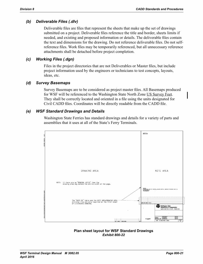
(e) WSF Standard Drawings and DetailsWashington State Ferries has standard drawings and details for a variety of parts and assemblies that it uses at all of the State’s Ferry Terminals.
CADD Standards and Procedures Division 800
Terminal Design Manual M 3082 Page 800-6-23March 2014
(c) Working Files (.dgn)Files in the project directories that are not Deliverables or Master files, but include project information used by the engineers or technicians to test concepts, layouts, ideas, etc.
(d) Survey BasemapsSurvey Basemaps are to be considered as project master files. All Basemaps produced for WSF will be referenced to the Washington State North Zone US Survey Feet. They shall be correctly located and oriented in a file using the units designated for Civil CADD files. Coordinates will be directly readable from the CADD file.
(e) WSF Standard Drawings and DetailsWashington State Ferries has standard drawings and details for a variety of parts and assemblies that it uses at all of the State’s Ferry Terminals.
Exhibit 800-22: Plan sheet layout for WSF Standard Drawings
(f) Backup FilesBackup files for project design shall only be created when a major revision to a Deliverable file is made. The backup is made so that if the revision is found to be in error a copy of the file, as it existed immediately prior to the change, will still exist.
The naming of a Backup file shall be the same as for a Deliverable file (see pg. 24 –Deliverable Files) except that the file extension will be “. bak” instead of “.dlv”.
Plan sheet layout for WSF Standard DrawingsExhibit 800-22
CADD Standards and Procedures Division 8
Page 800-22 WSF Terminal Design Manual M 3082.05 April 2016
(f) Backup FilesBackup files for project design shall only be created when a major revision to a Deliverable file is made. The backup is made so that if the revision is found to be in error a copy of the file, as it existed immediately prior to the change, will still exist.
The naming of a Backup file shall be the same as for a Deliverable file (see pg. 24 – Deliverable Files) except that the file extension will be “. bak” instead of “.dlv”.
Backup files are not to be created for the sole purpose of retaining a copy of the plan set at review points. If the Project Manager decides that a copy of the plans at review point is necessary a CD will be created to store the required contents of the project directory.
At project completion all backup files will be removed from the directory prior to archiving.
WSF keeps weekly backups of its main servers off-site at a secure storage facility. A request to restore the desired file shall be forwarded to the WSF IT Help Desk and will include:• The last known “good” date of the file• The Server that the file was housed on• The name and directory path that the file can be found in
The Help desk can be contacted by email at [email protected] or at 206-515-3800. In house CADD users can contact the Help desk by dialing “3800” on their phone.
Allow 2 to 3 working days for retrieval of the file.
Please note: The weekly tapes are archived for a term of one (1) year only. If you need to retrieve a file older than that you will either find it in the U drive archives (for in-house personnel) or you won’t find it.
806.02 File NamingThe “File Name” is the unique identification for each drawing. It is from a minimum of 12 to a maximum of 24 characters in length and is alpha/numeric in character. There will be no spaces in the file name. If a space is necessary then either the underscore symbol (“_”) or the hyphen (“-“) shall be used. Each design drawing shall be assigned a drawing number. The drawing numbering is defined by the discipline and plan number within that discipline.
Division 8 CADD Standards and Procedures
WSF Terminal Design Manual M 3082.05 Page 800-23 April 2016
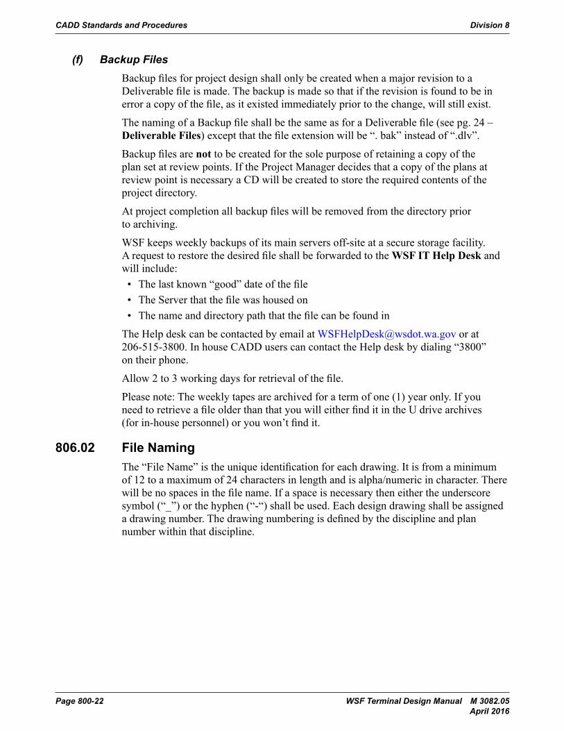
(a) Discipline DesignatorsExhibit 800-23 shows discipline designators for typical disciplines used by both master files and deliverables. These numbers will be listed on the project drawing list.
Designator Disciplinea Architectural c Civil d Design Reporte Electrical f Fire Protectiong Generalh Hydraulic Power Systemsi Instrumentation and Control Systemsk Cathodic Protectionl Lightingls Landscape(& Irrigation)m Mechanicalp Permittings Structural sc Securityt Telecommunicationsu Site Utilities
Discipline DesignatorsExhibit 800-23
(b) Master FilesThose files created for the project that become the project Master files shall be named using the following criteria:
Where, xαα##βχd_#……...# .mst
x = e => if the file contains existing information p = > if the file contains proposed information d = > if the file contains demolition information αα##βχ = The project identification number (See Project Naming). d = Discipline Designator. See Table 1 – 6.02.01 #…….# = Short description of work location – Maximum of 13 characters. .mst = Suffix denoting a Master File.
Example: The original basemap depicting existing conditions used for the civil drawings for project number 09X053 would be named:
e09X053c_basemap.mst
CADD Standards and Procedures Division 8
Page 800-24 WSF Terminal Design Manual M 3082.05 April 2016
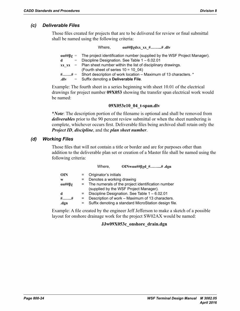
(c) Deliverable FilesThose files created for projects that are to be delivered for review or final submittal shall be named using the following criteria:
Where, αα##βχdxx_xx_#……...# .dlv
αα##βχ = The project identification number (supplied by the WSF Project Manager). d = Discipline Designation. See Table 1 – 6.02.01 xx_xx = Plan sheet number within the list of disciplinary drawings. (Fourth sheet of series 10 = 10_04) #…….# = Short description of work location – Maximum of 13 characters. * .dlv = Suffix denoting a Deliverable File.
Example: The fourth sheet in a series beginning with sheet 10.01 of the electrical drawings for project number 09X053 showing the transfer span electrical work would be named:
09X053e10_04_t-span.dlv
*Note: The description portion of the filename is optional and shall be removed from deliverables prior to the 90 percent review submittal or when the sheet numbering is complete, whichever occurs first. Deliverable files being archived shall retain only the Project ID, discipline, and the plan sheet number.
(d) Working FilesThose files that will not contain a title or border and are for purposes other than addition to the deliverable plan set or creation of a Master file shall be named using the following criteria:
Where, OINwαα##βχd_#……...# .dgn
OIN = Originator’s initials w = Denotes a working drawing αα##βχ = The numerals of the project identification number (supplied by the WSF Project Manager). d = Discipline Designation. See Table 1 – 6.02.01 #…….# = Description of work – Maximum of 13 characters. .dgn = Suffix denoting a standard MicroStation design file.
Example: A file created by the engineer Jeff Jefferson to make a sketch of a possible layout for onshore drainage work for the project SW02AX would be named:
JJw09X053c_onshore_drain.dgn
Division 8 CADD Standards and Procedures
WSF Terminal Design Manual M 3082.05 Page 800-25 April 2016
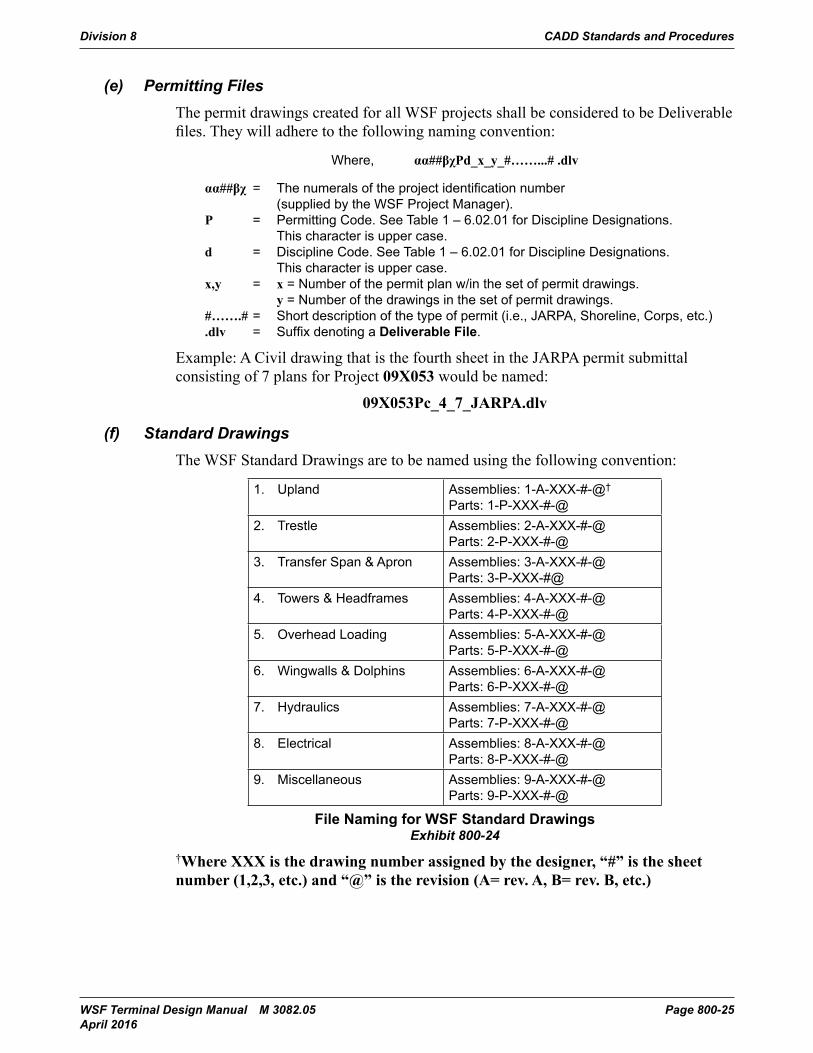
(e) Permitting FilesThe permit drawings created for all WSF projects shall be considered to be Deliverable files. They will adhere to the following naming convention:
Where, αα##βχPd_x_y_#……...# .dlv
αα##βχ = The numerals of the project identification number (supplied by the WSF Project Manager). P = Permitting Code. See Table 1 – 6.02.01 for Discipline Designations. This character is upper case. d = Discipline Code. See Table 1 – 6.02.01 for Discipline Designations. This character is upper case. x,y = x = Number of the permit plan w/in the set of permit drawings. y = Number of the drawings in the set of permit drawings. #…….# = Short description of the type of permit (i.e., JARPA, Shoreline, Corps, etc.) .dlv = Suffix denoting a Deliverable File.
Example: A Civil drawing that is the fourth sheet in the JARPA permit submittal consisting of 7 plans for Project 09X053 would be named:
09X053Pc_4_7_JARPA.dlv
(f) Standard DrawingsThe WSF Standard Drawings are to be named using the following convention:
1. Upland Assemblies: 1-A-XXX-#-@† Parts: 1-P-XXX-#-@
2. Trestle Assemblies: 2-A-XXX-#-@ Parts: 2-P-XXX-#-@
3. Transfer Span & Apron Assemblies: 3-A-XXX-#-@ Parts: 3-P-XXX-#@
4. Towers & Headframes Assemblies: 4-A-XXX-#-@ Parts: 4-P-XXX-#-@
5. Overhead Loading Assemblies: 5-A-XXX-#-@ Parts: 5-P-XXX-#-@
6. Wingwalls & Dolphins Assemblies: 6-A-XXX-#-@ Parts: 6-P-XXX-#-@
7. Hydraulics Assemblies: 7-A-XXX-#-@ Parts: 7-P-XXX-#-@
8. Electrical Assemblies: 8-A-XXX-#-@ Parts: 8-P-XXX-#-@
9. Miscellaneous Assemblies: 9-A-XXX-#-@ Parts: 9-P-XXX-#-@
File Naming for WSF Standard DrawingsExhibit 800-24
†Where XXX is the drawing number assigned by the designer, “#” is the sheet number (1,2,3, etc.) and “@” is the revision (A= rev. A, B= rev. B, etc.)
CADD Standards and Procedures Division 8
Page 800-26 WSF Terminal Design Manual M 3082.05 April 2016
Prior to naming the file, the designation must be obtained from the WSF employee responsible for the care and maintenance of the Standard Drawings.
Revisions of a Standard Drawing will be indicated by renaming the file. A letter will be added to the end of the name that corresponds to the revision number.
Example: The third revision of 3-A-051-2 would be
3-A-051-2-C.dlv
Completed Standard Drawings will be archived to the U:\Standard Drawings\CADD directory for local use.
Division 8 CADD Standards and Procedures
WSF Terminal Design Manual M 3082.05 Page 800-27 April 2016
807 Plan Sequence
807.01 Plan Sequence ListThe following is the general sequence for the required sheets that shall be used in assembling the plans for a WSF construction project:
I. General Sheets (See 800-12)
G01.00 - Project Index, Project Location and Vicinity Map (Combined for smaller projects)
G01.00 - Project Location and Vicinity Map (Separated for larger projects)
G01.01 - Project Index (Separated for larger projects)
G02.00 - Sundry Site Plan
SQ1 - Summary of Quantities Sheet (if more than one SQ2, SQ3, etc.) (These sheets are produced by a separate application called EBASE and are added to the plan set as hard copy)
II. Civil Plan Sheet Series (See 800-13)
III. Architectural Plan Sheet Series (per Architect submittal)
IV. Structural Plan Sheet Series (See 800-14)
V. Fluid Power Hydraulic Plan Sheet Series (See 800-15)
VI. Electrical Design Drawing Series (See 800-16)
VII. Mechanical Design Drawing Series (See 800-17)
Plan Sequence List
The preceding is a list of possible plan sheets, and is not intended to represent a project. The designer is to determine the actual plan sheets required to best depict the project. Even with logical combinations of plan sheet series, the following basic order of sheets shall be maintained:
1. Item Information (Quantity Tabulation/Structure Notes/Sign Specifications)
2. Plan Series (Site and Location specific drawings of the required work)
3. Details (Dimension and Material specific drawings of work noted in Plan Series)
CADD Standards and Procedures Division 8
Page 800-28 WSF Terminal Design Manual M 3082.05 April 2016
808 Drawing List
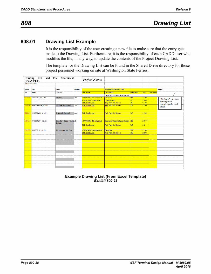
808.01 Drawing List ExampleIt is the responsibility of the user creating a new file to make sure that the entry gets made to the Drawing List. Furthermore, it is the responsibility of each CADD user who modifies the file, in any way, to update the contents of the Project Drawing List.
The template for the Drawing List can be found in the Shared Drive directory for those project personnel working on site at Washington State Ferries.
CADD Standards and Procedures Division 800
Page 800-8-30 Terminal Design Manual M 3082March 2014
808 Drawing List
808.01 Drawing List ExampleIt is the responsibility of the user creating a new file to make sure that the entry gets made to the Drawing List. Furthermore, it is the responsibility of each CADD user who modifies the file, in any way, to update the contents of the Project Drawing List.
The template for the Drawing List can be found in the Shared Drive directory for those project personnel working on site at Washington State Ferries.
Exhibit 800-25: Example Drawing List (From Excel Template)
Example Drawing List (From Excel Template)Exhibit 800-25
Division 8 CADD Standards and Procedures
WSF Terminal Design Manual M 3082.05 Page 800-29 April 2016
809 Drafting Standards
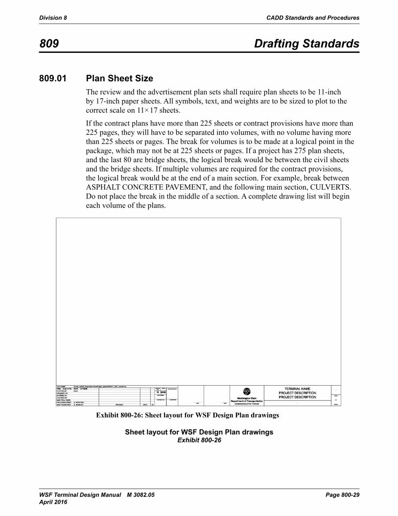
809.01 Plan Sheet SizeThe review and the advertisement plan sets shall require plan sheets to be 11-inch by 17-inch paper sheets. All symbols, text, and weights are to be sized to plot to the correct scale on 11×17 sheets.
If the contract plans have more than 225 sheets or contract provisions have more than 225 pages, they will have to be separated into volumes, with no volume having more than 225 sheets or pages. The break for volumes is to be made at a logical point in the package, which may not be at 225 sheets or pages. If a project has 275 plan sheets, and the last 80 are bridge sheets, the logical break would be between the civil sheets and the bridge sheets. If multiple volumes are required for the contract provisions, the logical break would be at the end of a main section. For example, break between ASPHALT CONCRETE PAVEMENT, and the following main section, CULVERTS. Do not place the break in the middle of a section. A complete drawing list will begin each volume of the plans.
CADD Standards and Procedures Division 800
Terminal Design Manual M 3082 Page 800-9-31March 2014
809 Drafting Standards
809.01 Plan Sheet SizeThe review and the advertisement plan sets shall require plan sheets to be 11-inch by 17-inch paper sheets. All symbols, text, and weights are to be sized to plot to the correct scale on 11x17 sheets.
If the contract plans have more than 225 sheets or contract provisions have more than 225 pages, they will have to be separated into volumes, with no volume having more than 225 sheets or pages. The break for volumes is to be made at a logical point in the package, which may not be at 225 sheets or pages. If a project has 275 plan sheets, and the last 80 are bridge sheets, the logical break would be between the civil sheets and the bridge sheets. If multiple volumes are required for the contract provisions, the logical break would be at the end of a main section. For example, break between ASPHALT CONCRETE PAVEMENT, and the following main section, CULVERTS. Do not place the break in the middle of a section. A complete drawing list will begin each volume of the plans.
Exhibit 800-26: Sheet layout for WSF Design Plan drawings
Sheet layout for WSF Design Plan drawingsExhibit 800-26
CADD Standards and Procedures Division 8
Page 800-30 WSF Terminal Design Manual M 3082.05 April 2016
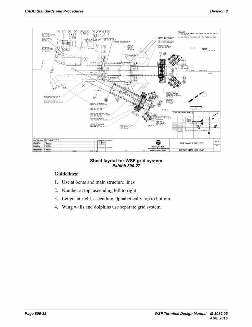
(a) Plan Sheet Grid SystemAll PS&E contract drawings will use a grid system. The grid system will be used on all applicable sheets to help locate placement of various sheets. (See Exhibit 800-27). The following is an explanation of how the grid system is placed.
Trestle, Tie-Up Slip, and Passenger Only Walkways:• Main rows of piles roughly aligned with the centerline of the trestle or the transfer
span will be designated by a letter. The designation will ascend from the row furthest left of the centerline (looking offshore) to the row furthest to the right of centerline.
• Pile bents oriented transversely to the trestle or transfer span centerline will be designated by a number. The designation will ascend from the bulkhead to the last bent of trestle piles furthest offshore.
• Piles found between the main rows and bents will be given either a “letter.#” designation or a “#.#” designation depending on whether it is more convenient to identify the piles as a bent or a row. (Example: a pile midway between bent 11 and 12 and midway between rows D and E could be designated as bent 11.5 or as row D.5)
Wingwalls:• Rows of piles that are parallel to the wingwall rub face will be designated by a
number. The numbers will ascend going from front to back of the wingwalls.• Rows of piles that are perpendicular to the wingwall rub face will be designated
by a letter. The letters will ascend progressing from closest onshore to furthest offshore.
• Any pile that doesn’t align with another pile will be given its own letter and number designations. Decimal designations will not be used for wingwalls.
Towers:• Rows of piles that are parallel to the transfer span centerline will be designated
with a letter. The letters will ascend progressing from the farthest from the transfer span centerline to the closest to the centerline.
• Rows of piles that are perpendicular to the transfer span centerline will be designated by a number. The numbers will ascend progressing from closest onshore to furthest offshore.
• Any pile that doesn’t align with another pile will be given its own letter and number designations. Decimal designations will not be used for towers.
Division 8 CADD Standards and Procedures
WSF Terminal Design Manual M 3082.05 Page 800-31 April 2016
Fixed Dolphins:
Fixed dolphins come in two different varieties, single sided and multisided. In the single sided type the face opposite the fenders is considered to be the back face. In the multisided type the side without fenders or the side closest onshore is considered to be the back side. In both varieties any piles that only support the fenders will be numbered in a clockwise direction, starting on the left. The numbering will continue from the last number used for pile designation within the diaphragm. The centerline of a dolphin will be that line that connects the center of the back face of the dolphin to the center of the opposite face. • Rows of piles that are parallel to the dolphin centerline will be designated with a
letter. The letters will ascend progressing from the furthest left of the centerline to the furthest right of the centerline.
• Rows of piles that are perpendicular to the dolphin centerline will be designated by a number. The numbers will ascend progressing from back of the dolphin to the front of the dolphin.
Floating Dolphins:
Floating dolphins are broken down into two parts, the floating dolphin itself, and the anchor system that holds the “floater” in place. The floater is made up of cast-in-place concrete placed in a cell structure. It is usually put in position with its long axis at a small angle from parallel to the slip centerline. The anchors are placed in relation to the floater and are either “in front” or “behind” it, with the front being closer to the centerline of the slip.• The “Floater” – the floater’s grid system utilizes all of the cast-in-place cell walls
to designate the grid lines. The walls that run parallel to the long axis of the floater are on lettered grid lines that ascend from the “back” to the “front” of the floater. The walls that run perpendicular to the long axis are labeled with a number and ascend from right to left when the floater is viewed from behind and looking toward centerline of the slip. The cells of the floater are designated by a number/letter pair that is taken from the lowest numbered and lettered grid lines that border them. An example would be: the cell that lays between grid lines C & D and 4&5 would be labeled cell 4C.
• The anchors are designated by a letter/number pair. The letter being either “B” or “F” depending on whether the anchor is in front of the floater or behind it. The number designation ascends from closest onshore to furthest offshore. Typical designations would be B1, B2… F1, F2, etc.
CADD Standards and Procedures Division 8
Page 800-32 WSF Terminal Design Manual M 3082.05 April 2016
CADD Standards and Procedures Division 800
Page 800-9-34 Terminal Design Manual M 3082March 2014
Exhibit 800-27: Sheet layout for WSF grid systemGuidelines:
1) Use at bents and main structure lines2) Number at top, ascending left to right3) Letters at right, ascending alphabetically top to bottom.4) Wing walls and dolphins use separate grid system.
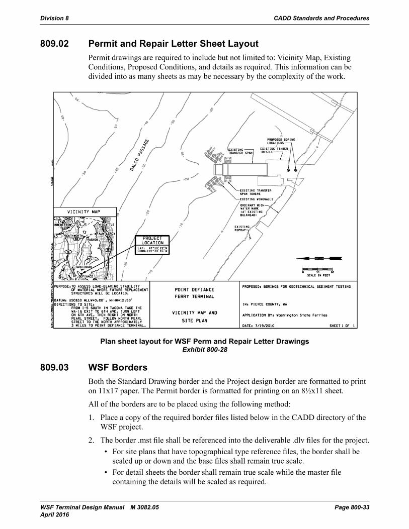
809.02 Permit and Repair Letter Sheet LayoutPermit drawings are required to include but not limited to: Vicinity Map, Existing Conditions, Proposed Conditions, and details as required. This information can be divided into as many sheets as may be necessary by the complexity of the work.
Sheet layout for WSF grid systemExhibit 800-27
Guidelines:
1. Use at bents and main structure lines
2. Number at top, ascending left to right
3. Letters at right, ascending alphabetically top to bottom.
4. Wing walls and dolphins use separate grid system.
Division 8 CADD Standards and Procedures
WSF Terminal Design Manual M 3082.05 Page 800-33 April 2016
809.02 Permit and Repair Letter Sheet LayoutPermit drawings are required to include but not limited to: Vicinity Map, Existing Conditions, Proposed Conditions, and details as required. This information can be divided into as many sheets as may be necessary by the complexity of the work.
CADD Standards and Procedures Division 800
Terminal Design Manual M 3082 Page 800-9-35March 2014
.Exhibit 800-28: Plan sheet layout for WSF Perm and Repair Letter Drawings
809.03 WSF BordersBoth the Standard Drawing border and the Project design border are formatted to print on 11x17 paper. The Permit border is formatted for printing on an 8½x11 sheet.
All of the borders are to be placed using the following method:
1. Place a copy of the required border files listed below in the CADD directory of the WSF project.
2. The border .mst file shall be referenced into the deliverable .dlv files for the project. o For site plans that have topographical type reference files, the border shall
be scaled up or down and the base files shall remain true scale.o For detail sheets the border shall remain true scale while the master file
containing the details will be scaled as required.
Text that is individual to each sheet shall be placed following the placement of the Title Block. This text will be part of the deliverable file but not part of the referenced files.
Plan sheet layout for WSF Perm and Repair Letter DrawingsExhibit 800-28
809.03 WSF BordersBoth the Standard Drawing border and the Project design border are formatted to print on 11x17 paper. The Permit border is formatted for printing on an 8½x11 sheet.
All of the borders are to be placed using the following method:
1. Place a copy of the required border files listed below in the CADD directory of the WSF project.
2. The border .mst file shall be referenced into the deliverable .dlv files for the project. • For site plans that have topographical type reference files, the border shall be
scaled up or down and the base files shall remain true scale.• For detail sheets the border shall remain true scale while the master file
containing the details will be scaled as required.
CADD Standards and Procedures Division 8
Page 800-34 WSF Terminal Design Manual M 3082.05 April 2016
Text that is individual to each sheet shall be placed following the placement of the Title Block. This text will be part of the deliverable file but not part of the referenced files.
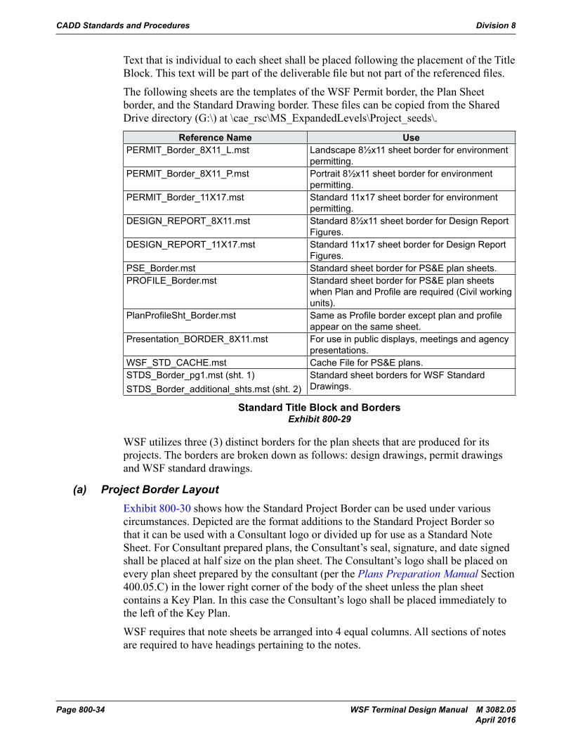
The following sheets are the templates of the WSF Permit border, the Plan Sheet border, and the Standard Drawing border. These files can be copied from the Shared Drive directory (G:\) at \cae_rsc\MS_ExpandedLevels\Project_seeds\.
Reference Name UsePERMIT_Border_8X11_L.mst Landscape 8½x11 sheet border for environment
permitting.PERMIT_Border_8X11_P.mst Portrait 8½x11 sheet border for environment
permitting.PERMIT_Border_11X17.mst Standard 11x17 sheet border for environment
permitting.DESIGN_REPORT_8X11.mst Standard 8½x11 sheet border for Design Report
Figures.DESIGN_REPORT_11X17.mst Standard 11x17 sheet border for Design Report
Figures.PSE_Border.mst Standard sheet border for PS&E plan sheets.PROFILE_Border.mst Standard sheet border for PS&E plan sheets
when Plan and Profile are required (Civil working units).
PlanProfileSht_Border.mst Same as Profile border except plan and profile appear on the same sheet.
Presentation_BORDER_8X11.mst For use in public displays, meetings and agency presentations.
WSF_STD_CACHE.mst Cache File for PS&E plans.STDS_Border_pg1.mst (sht. 1)STDS_Border_additional_shts.mst (sht. 2)
Standard sheet borders for WSF Standard Drawings.
Standard Title Block and BordersExhibit 800-29
WSF utilizes three (3) distinct borders for the plan sheets that are produced for its projects. The borders are broken down as follows: design drawings, permit drawings and WSF standard drawings.
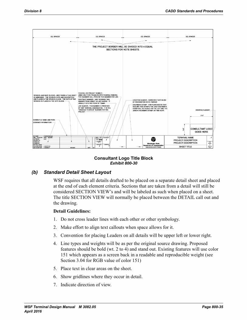
(a) Project Border LayoutExhibit 800-30 shows how the Standard Project Border can be used under various circumstances. Depicted are the format additions to the Standard Project Border so that it can be used with a Consultant logo or divided up for use as a Standard Note Sheet. For Consultant prepared plans, the Consultant’s seal, signature, and date signed shall be placed at half size on the plan sheet. The Consultant’s logo shall be placed on every plan sheet prepared by the consultant (per the Plans Preparation Manual Section 400.05.C) in the lower right corner of the body of the sheet unless the plan sheet contains a Key Plan. In this case the Consultant’s logo shall be placed immediately to the left of the Key Plan.
WSF requires that note sheets be arranged into 4 equal columns. All sections of notes are required to have headings pertaining to the notes.
Division 8 CADD Standards and Procedures
WSF Terminal Design Manual M 3082.05 Page 800-35 April 2016
CADD Standards and Procedures Division 800
Terminal Design Manual M 3082 Page 800-9-37March 2014
half size on the plan sheet. The Consultant’s logo shall be placed on every plan sheet prepared by the consultant (per the Plans Preparation Manual Section 400.05.C) in the lower right corner of the body of the sheet unless the plan sheet contains a Key Plan. In this case the Consultant’s logo shall be placed immediately to the left of the Key Plan.
WSF requires that note sheets be arranged into 4 equal columns. All sections of notes are required to have headings pertaining to the notes.
Exhibit 800-30: Consultant Logo Title Block
(b) Standard Detail Sheet LayoutWSF requires that all details drafted to be placed on a separate detail sheet and placed at the end of each element criteria. Sections that are taken from a detail will still be considered SECTION VIEW’s and will be labeled as such when placed on a sheet. The title SECTION VIEW will normally be placed between the DETAIL call out and the drawing.
Detail Guidelines:
1. Do not cross leader lines with each other or other symbology.2. Make effort to align text callouts when space allows for it.3.Convention for placing Leaders on all details will be upper left or lower right.4. Line types and weights will be as per the original source drawing. Proposed
features should be bold (wt. 2 to 4) and stand out. Existing features will use color
Consultant Logo Title BlockExhibit 800-30
(b) Standard Detail Sheet LayoutWSF requires that all details drafted to be placed on a separate detail sheet and placed at the end of each element criteria. Sections that are taken from a detail will still be considered SECTION VIEW’s and will be labeled as such when placed on a sheet. The title SECTION VIEW will normally be placed between the DETAIL call out and the drawing.
Detail Guidelines:
1. Do not cross leader lines with each other or other symbology.
2. Make effort to align text callouts when space allows for it.
3. Convention for placing Leaders on all details will be upper left or lower right.
4. Line types and weights will be as per the original source drawing. Proposed features should be bold (wt. 2 to 4) and stand out. Existing features will use color 151 which appears as a screen back in a readable and reproducible weight (see Section 3.04 for RGB value of color 151)
5. Place text in clear areas on the sheet.
6. Show gridlines where they occur in detail.
7. Indicate direction of view.
CADD Standards and Procedures Division 8
Page 800-36 WSF Terminal Design Manual M 3082.05 April 2016
(c) Standard Section Sheet LayoutSections are used to create a view perpendicular to the original source drawing. They are used to create a larger view of an area in the same orientation as the original. Sections are intended to provide detailed information at a larger horizontal or vertical distance than detail. When applicable, show gridline information in the section, thus giving a reference to where the information is relative to other sheet files. When putting sections together the information that is being cut should be dark and prominent where as all other information is considered beyond and grayed back, but readable and reproducible.
Section Guidelines:
1. Do not cross leader lines with each other or other symbology.
2. Make effort to align text callouts when space allows for it.
3. Convention for placing Leaders on all sections will be upper left or lower right.
4. Line types and weights will be as per the original source drawing.
5. Proposed features should be bold (wt. 2 to 4) and stand out.
6. Existing features will use color 151 which appears as a screen back in a readable and reproducible weight.
7. Place text in clear areas on the sheet.
8. Show gridlines where they occur in section.
9. Indicate direction of view.
Division 8 CADD Standards and Procedures
WSF Terminal Design Manual M 3082.05 Page 800-37 April 2016
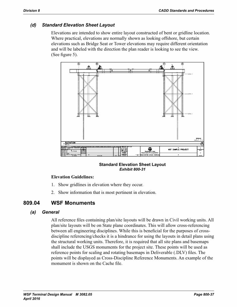
(d) Standard Elevation Sheet LayoutElevations are intended to show entire layout constructed of bent or gridline location. Where practical, elevations are normally shown as looking offshore, but certain elevations such as Bridge Seat or Tower elevations may require different orientation and will be labeled with the direction the plan reader is looking to see the view. (See figure 5).
CADD Standards and Procedures Division 800
Terminal Design Manual M 3082 Page 800-9-39March 2014
Exhibit 800-31: Standard Elevation Sheet Layout
Elevation Guidelines:
1. Show gridlines in elevation where they occur.2. Show information that is most pertinent in elevation.
809.04 WSF Monuments
(a) GeneralAll reference files containing plan/site layouts will be drawn in Civil working units. All plan/site layouts will be on State plane coordinates. This will allow cross-referencing between all engineering disciplines. While this is beneficial for the purposes of cross-discipline referencing/checks it is a hindrance for using the layouts in detail plans using the structural working units. Therefore, it is required that all site plans and basemaps shall include the USGS monuments for the project site. These points will be used as reference points for scaling and rotating basemaps in Deliverable (.DLV) files. The points will be displayed as Cross-Discipline Reference Monuments. An example of the monument is shown on the Cache file.
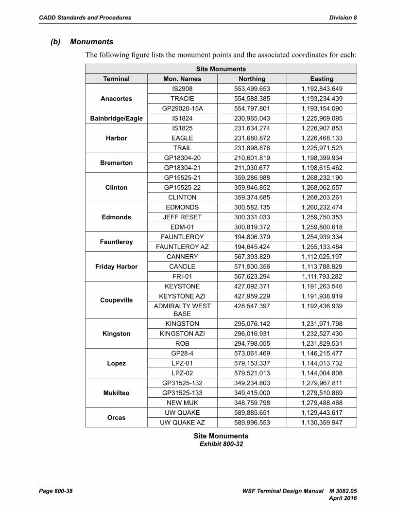
(b) MonumentsThe following figure lists the monument points and the associated coordinates for each:
SITE MONUMENTSTERMINAL MON. NAMES NORTHING EASTING
Anacortes IS2908 553,499.653 1,192,843.649TRACIE 554,588.385 1,193,234.439
Standard Elevation Sheet LayoutExhibit 800-31
Elevation Guidelines:
1. Show gridlines in elevation where they occur.
2. Show information that is most pertinent in elevation.
809.04 WSF Monuments(a) General
All reference files containing plan/site layouts will be drawn in Civil working units. All plan/site layouts will be on State plane coordinates. This will allow cross-referencing between all engineering disciplines. While this is beneficial for the purposes of cross-discipline referencing/checks it is a hindrance for using the layouts in detail plans using the structural working units. Therefore, it is required that all site plans and basemaps shall include the USGS monuments for the project site. These points will be used as reference points for scaling and rotating basemaps in Deliverable (.DLV) files. The points will be displayed as Cross-Discipline Reference Monuments. An example of the monument is shown on the Cache file.
CADD Standards and Procedures Division 8
Page 800-38 WSF Terminal Design Manual M 3082.05 April 2016
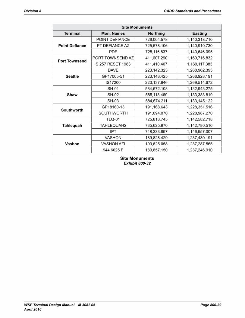
(b) MonumentsThe following figure lists the monument points and the associated coordinates for each:
Site MonumentsTerminal Mon. Names Northing Easting
AnacortesIS2908 553,499.653 1,192,843.649TRACIE 554,588.385 1,193,234.439
GP29020-15A 554,797.801 1,193,154.090Bainbridge/Eagle IS1824 230,965.043 1,225,969.095
HarborIS1825 231,634.274 1,226,907.853EAGLE 231,680.872 1,226,468.133TRAIL 231,898.876 1,225,971.523
BremertonGP18304-20 210,601.819 1,198,399.934GP18304-21 211,030.677 1,198,615.462
ClintonGP15525-21 359,286.988 1,268,232.190GP15525-22 359,946.852 1,268,062.557
CLINTON 359,374.685 1,268,203.261
EdmondsEDMONDS 300,582.135 1,260,232.474
JEFF RESET 300,331.033 1,259,750.353EDM-01 300,819.372 1,259,800.618
FauntleroyFAUNTLEROY 194,806.379 1,254,939.334
FAUNTLEROY AZ 194,645.424 1,255,133.484
Friday HarborCANNERY 567,393.829 1,112,025.197CANDLE 571,500.356 1,113,788.829FRI-01 567,623.294 1,111,793.282
Coupeville
KEYSTONE 427,092.371 1,191,263.546KEYSTONE AZI 427,959.229 1,191,938.919
ADMIRALTY WEST BASE
428,547.397 1,192,436.939
KingstonKINGSTON 295,076.142 1,231,971.798
KINGSTON AZI 296,016.931 1,232,527.430ROB 294,798.055 1,231,829.531
LopezGP28-4 573,061.469 1,146,215.477LPZ-01 579,153.337 1,144,013.732LPZ-02 579,521.013 1,144,004.808
MukilteoGP31525-132 349,234.803 1,279,967.811GP31525-133 349,415.000 1,279,510.869
NEW MUK 348,759.798 1,279,488.468
OrcasUW QUAKE 589,885.651 1,129,443.617
UW QUAKE AZ 589,996.553 1,130,359.947
Site MonumentsExhibit 800-32
Division 8 CADD Standards and Procedures
WSF Terminal Design Manual M 3082.05 Page 800-39 April 2016
Site MonumentsTerminal Mon. Names Northing Easting
Point DefiancePOINT DEFIANCE 726,004.578 1,140,318.710PT DEFIANCE AZ 725,578.106 1,140,910.730
PDF 725,116.837 1,140,646.095
Port TownsendPORT TOWNSEND AZ 411,607.290 1,169,716.832
S 257 RESET 1983 411,410.407 1,169,117.383
SeattleDAVE 223,142.323 1,268,962.393
GP17005-51 223,148.425 1,268,928.191IS17200 223,137.946 1,269,514.672
ShawSH-01 584,672.108 1,132,943.275SH-02 585,118.469 1,133,383.819SH-03 584,674.211 1,133,145.122
SouthworthGP18160-13 191,168.643 1,228,351.516
SOUTHWORTH 191,094.070 1,228,987.270
TahlequahTLQ-01 725,818.745 1,142,582.718
TAHLEQUAH2 735,625.970 1,142,780.516IPT 748,333.897 1,146,957.007
VashonVASHON 189,828.429 1,237,430.191
VASHON AZI 190,625.058 1,237,287.565944 6025 F 189,857.150 1,237,246.910
Site MonumentsExhibit 800-32
CADD Standards and Procedures Division 8
Page 800-40 WSF Terminal Design Manual M 3082.05 April 2016
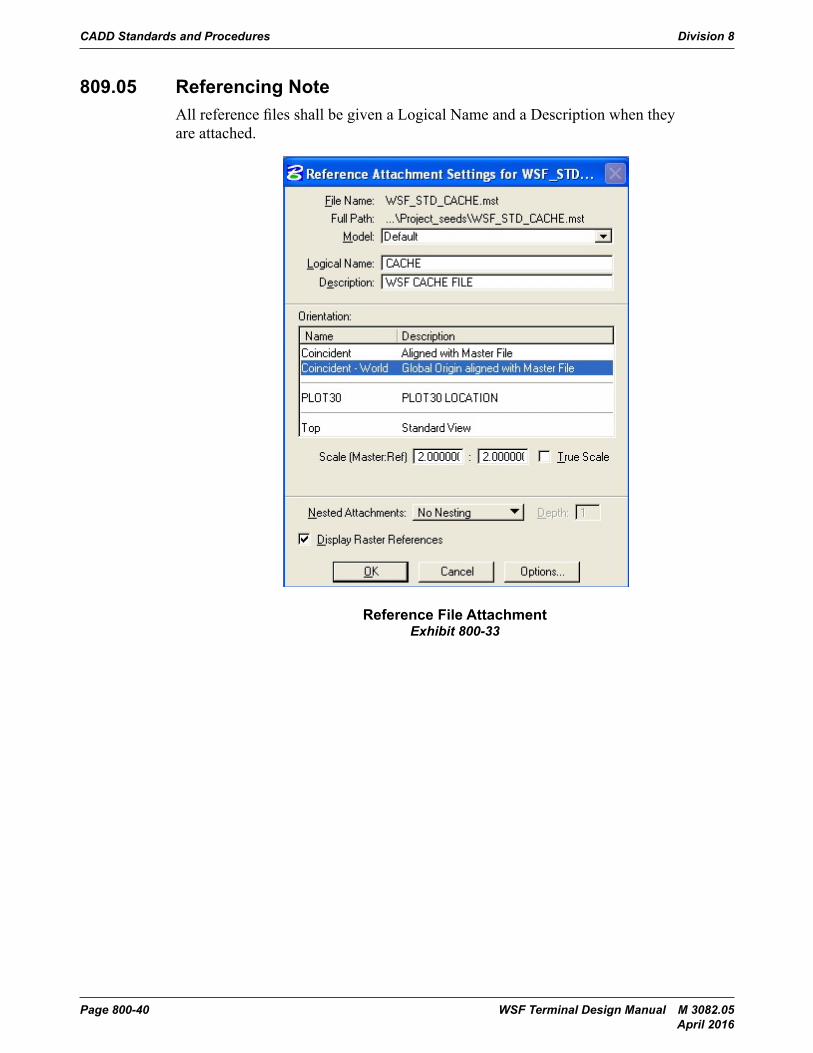
809.05 Referencing NoteAll reference files shall be given a Logical Name and a Description when they are attached.
CADD Standards and Procedures Division 800
Page 800-9-42 Terminal Design Manual M 3082March 2014
809.05 Referencing NoteAll reference files shall be given a Logical Name and a Description when they are attached.
Exhibit 800-32: Reference File Attachment
809.06 Sheet NumberingThe Drawing Number shall be placed in the upper right-hand corner of the Title Block. The font shall be font 200 and will be scaled to 1.33 times the standard text size as it appears on the standard plan sheet border.
The Index Numbers shall be placed in the lower right-hand corner of the Title Block. The font shall be font 200 and will be scaled to the standard text size as it appears on the standard plan sheet border. It will have a line spacing of 2.5.
The format for sheet numbering shall be:
Dxx.xx
Where,
D Discipline designation (from Table 1 – 6.02.01)
Reference File AttachmentExhibit 800-33
Division 8 CADD Standards and Procedures
WSF Terminal Design Manual M 3082.05 Page 800-41 April 2016
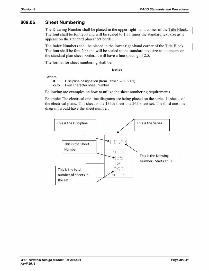
809.06 Sheet NumberingThe Drawing Number shall be placed in the upper right-hand corner of the Title Block. The font shall be font 200 and will be scaled to 1.33 times the standard text size as it appears on the standard plan sheet border.
The Index Numbers shall be placed in the lower right-hand corner of the Title Block. The font shall be font 200 and will be scaled to the standard text size as it appears on the standard plan sheet border. It will have a line spacing of 2.5.
The format for sheet numbering shall be:
Dxx.xx
Where, D Discipline designation (from Table 1 – 6.02.01) xx.xx Four character sheet number
Following are examples on how to utilize the sheet numbering requirements.
Example: The electrical one-line diagrams are being placed on the series 11 sheets of the electrical plans. This sheet is the 135th sheet in a 265-sheet set. The third one-line diagram would have the sheet number:
CADD Standards and Procedures Division 800
Page 800-9-8 Terminal Design Manual M 3082March 2014
809.05 Referencing Note
809.06 Sheet Numbering
Example: The electrical one-line diagrams are being placed on the series 11 sheets of the electrical plans. This sheet is the 135th sheet in a 265-sheet set. The third one-line diagram would have the sheet number:
This is the Drawing Number. Starts at .00
This is the total number of sheets in the set.
This is the Sheet Number
This is the Discipline This is the Series
CADD Standards and Procedures Division 8
Page 800-42 WSF Terminal Design Manual M 3082.05 April 2016
809.07 Text(a) General
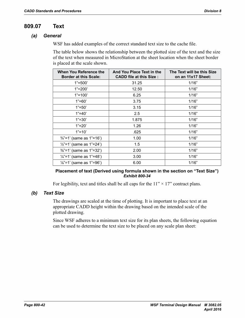
WSF has added examples of the correct standard text size to the cache file.
The table below shows the relationship between the plotted size of the text and the size of the text when measured in MicroStation at the sheet location when the sheet border is placed at the scale shown.
When You Reference the Border at this Scale:
And You Place Text in the CADD file at this Size :
The Text will be this Size on an 11x17 Sheet:
1”=500’ 31.25 1/16”1”=200’ 12.50 1/16”1”=100’ 6.25 1/16”1”=60’ 3.75 1/16”1”=50’ 3.15 1/16”1”=40’ 2.5 1/16”1”=30’ 1.875 1/16”1”=20’ 1.26 1/16”1”=10’ .625 1/16”
¾”=1’ (same as 1”=16’) 1.00 1/16”½”=1’ (same as 1”=24’) 1.5 1/16”⅜”=1’ (same as 1”=32’) 2.00 1/16”¼”=1’ (same as 1”=48’) 3.00 1/16”⅛”=1’ (same as 1”=96’) 6.00 1/16”
Placement of text (Derived using formula shown in the section on “Text Size”)Exhibit 800-34
For legibility, text and titles shall be all caps for the 11” × 17” contract plans.
(b) Text SizeThe drawings are scaled at the time of plotting. It is important to place text at an appropriate CADD height within the drawing based on the intended scale of the plotted drawing.
Since WSF adheres to a minimum text size for its plan sheets, the following equation can be used to determine the text size to be placed on any scale plan sheet:
Division 8 CADD Standards and Procedures
WSF Terminal Design Manual M 3082.05 Page 800-43 April 2016
Ts = Tp x Ss
Where, Tp = text size on the paper (11x17)(inches) Ts = text size in the “CACHE” file (feet) Ss = sheet border scale (feet/inches)
Example: You want to place text onto a 1”=50’ scale sheet so that it measures 1/16 ” (.0625”)
So,Ts = Tp x Ss
Becomes,Ts = (.0625”)x 50
Thus,Ts = 3.125
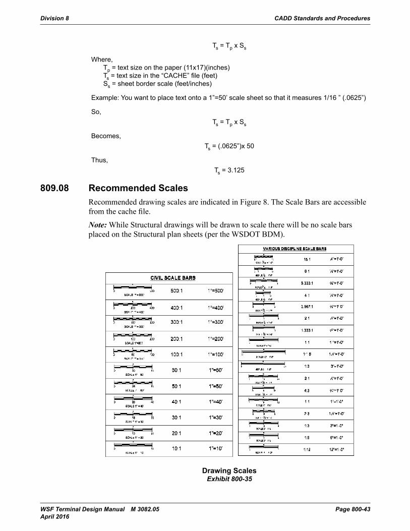
809.08 Recommended ScalesRecommended drawing scales are indicated in Figure 8. The Scale Bars are accessible from the cache file.
Note: While Structural drawings will be drawn to scale there will be no scale bars placed on the Structural plan sheets (per the WSDOT BDM).
CADD Standards and Procedures Division 800
Terminal Design Manual M 3082 Page 800-9-45March 2014
809.08 Recommended ScalesRecommended drawing scales are indicated in Figure 8. The Scale Bars are accessible from the cache file.
NOTE: While Structural drawings will be drawn to scale there will be no scale bars placed on the Structural plan sheets (per the WSDOT BDM).
Exhibit 800-33: Drawing ScalesDrawing ScalesExhibit 800-35
CADD Standards and Procedures Division 8
Page 800-44 WSF Terminal Design Manual M 3082.05 April 2016
809.09 Addendums, Revisions and Change OrdersWSF uses the same method for identifying changes to drawings during the addendum and change order processes as WSDOT. Examples of Addenda, Revisions, and Change Order Documents can be found in the Plans Preparation Manual Appendix 5 “Addendum Preparation”. Additionally WSF uses “clouding” and revision triangles to indicate changes to the WSF Standard drawings. Specific changes to these drawings are clouded and appended with a revision triangle. Upon a new revision to the drawing the clouding from the previous revision is removed but the revision triangle remains as a note that the drawing has been previously revised.
809.10 Preliminary StampsAll plan sheets are required to have a “Preliminary” or “Submittal” Stamp in the lower left corner until the final printing before sending to Olympia. This text is located in the WSF_STD_CACHE.mst file and should be placed in the project’s PSE_Border.mst file, not in the deliverable file.
809.11 Element SymbologyThe use and application of the element attributes defined in this section shall be uniformly observed for the following reasons:
1. Work Transfer – To efficiently transfer work between functional units, CADD drawings must conform to a uniform data base arrangement - levels, etc. If all units do not use the same system, considerable time can be lost in learning a new system when work is transferred.
2. Multi-Operators – It is not uncommon for more than one person to work on the same drawing. For the level attributes to be meaningful, each operator must conform to a common level definition.
3. Drawing Life – At WSF, drawings are active for several years. How the data is entered today (i.e., what levels are used for what kinds of data) must be readily apparent for a long period. This problem is minimized with a uniform definition and use of the various levels.
809.12 Civil and Right-of-Way Level SymbologyWSF uses the WSDOT Level and Symbology (line color, style, and weight) schemes as found in the Plans Preparation Manual Division 3 and Division 5 for “onshore” work. All “offshore” work will utilize the WSF leveling schemes. Elements of work that bridge the gap between “onshore” and “offshore”, an overhead loading system for example, will utilize WSF symbology until the point that they become an integral part of the “onshore” structure. The determination of this “point” will be made by the State.
Division 8 CADD Standards and Procedures
WSF Terminal Design Manual M 3082.05 Page 800-45 April 2016
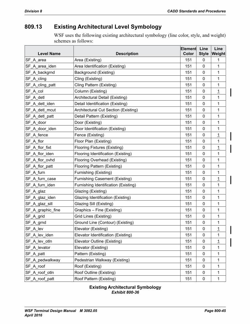
809.13 Existing Architectural Level SymbologyWSF uses the following existing architectural symbology (line color, style, and weight) schemes as follows:
Level Name DescriptionElement
ColorLine Style
Line Weight
SF_A_area Area (Existing) 151 0 1SF_A_area_iden Area Identification (Existing) 151 0 1SF_A_backgrnd Background (Existing) 151 0 1SF_A_cling Cling (Existing) 151 0 1SF_A_cling_patt Cling Pattern (Existing) 151 0 1SF_A_col Column (Existing) 151 0 1SF_A_detl Architectural Detail (Existing) 151 0 1SF_A_detl_iden Detail Identification (Existing) 151 0 1SF_A_detl_mcut Architectural Cut Section (Existing) 151 0 1SF_A_detl_patt Detail Pattern (Existing) 151 0 1SF_A_door Door (Existing) 151 0 1SF_A_door_iden Door Identification (Existing) 151 0 1SF_A_fence Fence (Existing) 151 0 1SF_A_flor Floor Plan (Existing) 151 0 1SF_A_flor_fixt Flooring Fixtures (Existing) 151 0 1SF_A_flor_iden Flooring Identification (Existing) 151 0 1SF_A_flor_ovhd Flooring Overhead (Existing) 151 0 1SF_A_flor_patt Flooring Pattern (Existing) 151 0 1SF_A_furn Furnishing (Existing) 151 0 1SF_A_furn_case Furnishing Casement (Existing) 151 0 1SF_A_furn_iden Furnishing Identification (Existing) 151 0 1SF_A_glaz Glazing (Existing) 151 0 1SF_A_glaz_iden Glazing Identification (Existing) 151 0 1SF_A_glaz_sill Glazing Sill (Existing) 151 0 1SF_A_graphic_fine Graphics – Fine (Existing) 151 0 1SF_A_grid Grid Lines (Existing) 151 0 1SF_A_grnd Ground Line (Contour) (Existing) 151 0 1SF_A_lev Elevator (Existing) 151 0 1SF_A_lev_iden Elevator Identification (Existing) 151 0 1SF_A_lev_otln Elevator Outline (Existing) 151 0 1SF_A_levator Elevator (Existing) 151 0 1SF_A_patt Pattern (Existing) 151 0 1SF_A_pedwalkway Pedestrian Walkway (Existing) 151 0 1SF_A_roof Roof (Existing) 151 0 1SF_A_roof_otln Roof Outline (Existing) 151 0 1SF_A_roof_patt Roof Pattern (Existing) 151 0 1
Existing Architectural SymbologyExhibit 800-36
CADD Standards and Procedures Division 8
Page 800-46 WSF Terminal Design Manual M 3082.05 April 2016
Level Name DescriptionElement
ColorLine Style
Line Weight
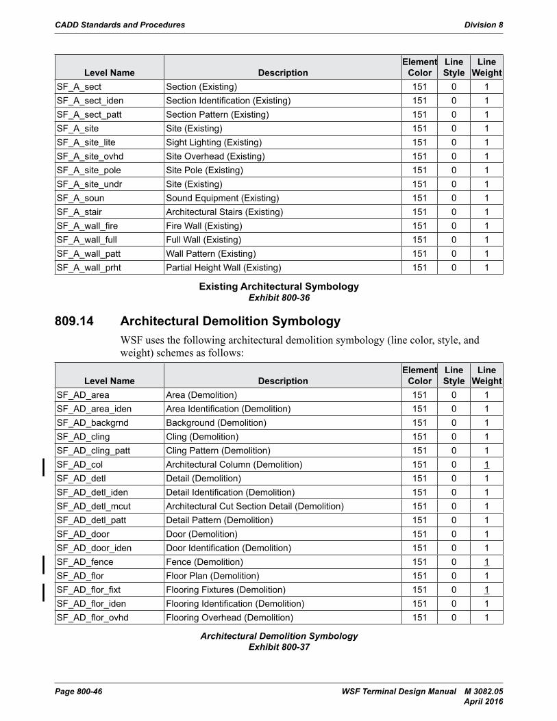
SF_A_sect Section (Existing) 151 0 1SF_A_sect_iden Section Identification (Existing) 151 0 1SF_A_sect_patt Section Pattern (Existing) 151 0 1SF_A_site Site (Existing) 151 0 1SF_A_site_lite Sight Lighting (Existing) 151 0 1SF_A_site_ovhd Site Overhead (Existing) 151 0 1SF_A_site_pole Site Pole (Existing) 151 0 1SF_A_site_undr Site (Existing) 151 0 1SF_A_soun Sound Equipment (Existing) 151 0 1SF_A_stair Architectural Stairs (Existing) 151 0 1SF_A_wall_fire Fire Wall (Existing) 151 0 1SF_A_wall_full Full Wall (Existing) 151 0 1SF_A_wall_patt Wall Pattern (Existing) 151 0 1SF_A_wall_prht Partial Height Wall (Existing) 151 0 1
Existing Architectural SymbologyExhibit 800-36
809.14 Architectural Demolition SymbologyWSF uses the following architectural demolition symbology (line color, style, and weight) schemes as follows:
Level Name DescriptionElement
ColorLine Style
Line Weight
SF_AD_area Area (Demolition) 151 0 1SF_AD_area_iden Area Identification (Demolition) 151 0 1SF_AD_backgrnd Background (Demolition) 151 0 1SF_AD_cling Cling (Demolition) 151 0 1SF_AD_cling_patt Cling Pattern (Demolition) 151 0 1SF_AD_col Architectural Column (Demolition) 151 0 1SF_AD_detl Detail (Demolition) 151 0 1SF_AD_detl_iden Detail Identification (Demolition) 151 0 1SF_AD_detl_mcut Architectural Cut Section Detail (Demolition) 151 0 1SF_AD_detl_patt Detail Pattern (Demolition) 151 0 1SF_AD_door Door (Demolition) 151 0 1SF_AD_door_iden Door Identification (Demolition) 151 0 1SF_AD_fence Fence (Demolition) 151 0 1SF_AD_flor Floor Plan (Demolition) 151 0 1SF_AD_flor_fixt Flooring Fixtures (Demolition) 151 0 1SF_AD_flor_iden Flooring Identification (Demolition) 151 0 1SF_AD_flor_ovhd Flooring Overhead (Demolition) 151 0 1
Architectural Demolition SymbologyExhibit 800-37
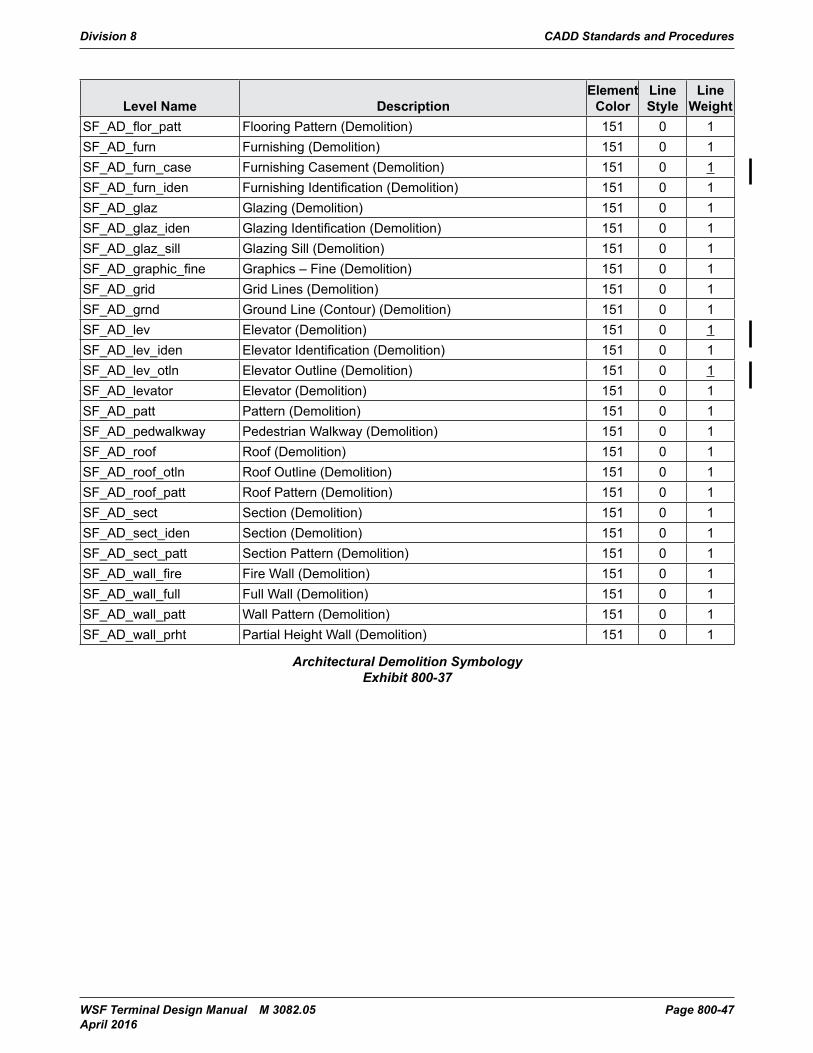
Division 8 CADD Standards and Procedures
WSF Terminal Design Manual M 3082.05 Page 800-47 April 2016
Level Name DescriptionElement
ColorLine Style
Line Weight
SF_AD_flor_patt Flooring Pattern (Demolition) 151 0 1SF_AD_furn Furnishing (Demolition) 151 0 1SF_AD_furn_case Furnishing Casement (Demolition) 151 0 1SF_AD_furn_iden Furnishing Identification (Demolition) 151 0 1SF_AD_glaz Glazing (Demolition) 151 0 1SF_AD_glaz_iden Glazing Identification (Demolition) 151 0 1SF_AD_glaz_sill Glazing Sill (Demolition) 151 0 1SF_AD_graphic_fine Graphics – Fine (Demolition) 151 0 1SF_AD_grid Grid Lines (Demolition) 151 0 1SF_AD_grnd Ground Line (Contour) (Demolition) 151 0 1SF_AD_lev Elevator (Demolition) 151 0 1SF_AD_lev_iden Elevator Identification (Demolition) 151 0 1SF_AD_lev_otln Elevator Outline (Demolition) 151 0 1SF_AD_levator Elevator (Demolition) 151 0 1SF_AD_patt Pattern (Demolition) 151 0 1SF_AD_pedwalkway Pedestrian Walkway (Demolition) 151 0 1SF_AD_roof Roof (Demolition) 151 0 1SF_AD_roof_otln Roof Outline (Demolition) 151 0 1SF_AD_roof_patt Roof Pattern (Demolition) 151 0 1SF_AD_sect Section (Demolition) 151 0 1SF_AD_sect_iden Section (Demolition) 151 0 1SF_AD_sect_patt Section Pattern (Demolition) 151 0 1SF_AD_wall_fire Fire Wall (Demolition) 151 0 1SF_AD_wall_full Full Wall (Demolition) 151 0 1SF_AD_wall_patt Wall Pattern (Demolition) 151 0 1SF_AD_wall_prht Partial Height Wall (Demolition) 151 0 1
Architectural Demolition SymbologyExhibit 800-37
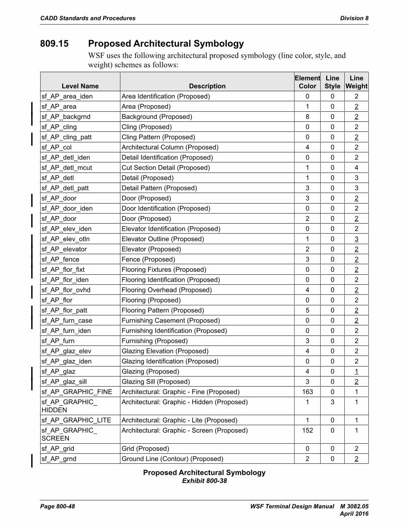
CADD Standards and Procedures Division 8
Page 800-48 WSF Terminal Design Manual M 3082.05 April 2016
809.15 Proposed Architectural SymbologyWSF uses the following architectural proposed symbology (line color, style, and weight) schemes as follows:
Level Name DescriptionElement
ColorLine Style
Line Weight
sf_AP_area_iden Area Identification (Proposed) 0 0 2sf_AP_area Area (Proposed) 1 0 2sf_AP_backgrnd Background (Proposed) 8 0 2sf_AP_cling Cling (Proposed) 0 0 2sf_AP_cling_patt Cling Pattern (Proposed) 0 0 2sf_AP_col Architectural Column (Proposed) 4 0 2sf_AP_detl_iden Detail Identification (Proposed) 0 0 2sf_AP_detl_mcut Cut Section Detail (Proposed) 1 0 4sf_AP_detl Detail (Proposed) 1 0 3sf_AP_detl_patt Detail Pattern (Proposed) 3 0 3sf_AP_door Door (Proposed) 3 0 2sf_AP_door_iden Door Identification (Proposed) 0 0 2sf_AP_door Door (Proposed) 2 0 2sf_AP_elev_iden Elevator Identification (Proposed) 0 0 2sf_AP_elev_otln Elevator Outline (Proposed) 1 0 3sf_AP_elevator Elevator (Proposed) 2 0 2sf_AP_fence Fence (Proposed) 3 0 2sf_AP_flor_fixt Flooring Fixtures (Proposed) 0 0 2sf_AP_flor_iden Flooring Identification (Proposed) 0 0 2sf_AP_flor_ovhd Flooring Overhead (Proposed) 4 0 2sf_AP_flor Flooring (Proposed) 0 0 2sf_AP_flor_patt Flooring Pattern (Proposed) 5 0 2sf_AP_furn_case Furnishing Casement (Proposed) 0 0 2sf_AP_furn_iden Furnishing Identification (Proposed) 0 0 2sf_AP_furn Furnishing (Proposed) 3 0 2sf_AP_glaz_elev Glazing Elevation (Proposed) 4 0 2sf_AP_glaz_iden Glazing Identification (Proposed) 0 0 2sf_AP_glaz Glazing (Proposed) 4 0 1sf_AP_glaz_sill Glazing Sill (Proposed) 3 0 2sf_AP_GRAPHIC_FINE Architectural: Graphic - Fine (Proposed) 163 0 1sf_AP_GRAPHIC_HIDDEN
Architectural: Graphic - Hidden (Proposed) 1 3 1
sf_AP_GRAPHIC_LITE Architectural: Graphic - Lite (Proposed) 1 0 1sf_AP_GRAPHIC_SCREEN
Architectural: Graphic - Screen (Proposed) 152 0 1
sf_AP_grid Grid (Proposed) 0 0 2sf_AP_grnd Ground Line (Contour) (Proposed) 2 0 2
Proposed Architectural SymbologyExhibit 800-38
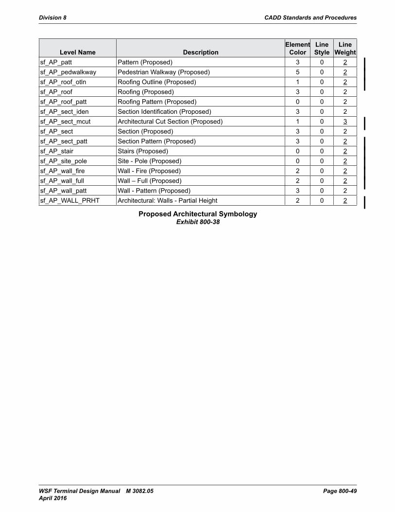
Division 8 CADD Standards and Procedures
WSF Terminal Design Manual M 3082.05 Page 800-49 April 2016
Level Name DescriptionElement
ColorLine Style
Line Weight
sf_AP_patt Pattern (Proposed) 3 0 2sf_AP_pedwalkway Pedestrian Walkway (Proposed) 5 0 2sf_AP_roof_otln Roofing Outline (Proposed) 1 0 2sf_AP_roof Roofing (Proposed) 3 0 2sf_AP_roof_patt Roofing Pattern (Proposed) 0 0 2sf_AP_sect_iden Section Identification (Proposed) 3 0 2sf_AP_sect_mcut Architectural Cut Section (Proposed) 1 0 3sf_AP_sect Section (Proposed) 3 0 2sf_AP_sect_patt Section Pattern (Proposed) 3 0 2sf_AP_stair Stairs (Proposed) 0 0 2sf_AP_site_pole Site - Pole (Proposed) 0 0 2sf_AP_wall_fire Wall - Fire (Proposed) 2 0 2sf_AP_wall_full Wall – Full (Proposed) 2 0 2sf_AP_wall_patt Wall - Pattern (Proposed) 3 0 2sf_AP_WALL_PRHT Architectural: Walls - Partial Height 2 0 2
Proposed Architectural SymbologyExhibit 800-38
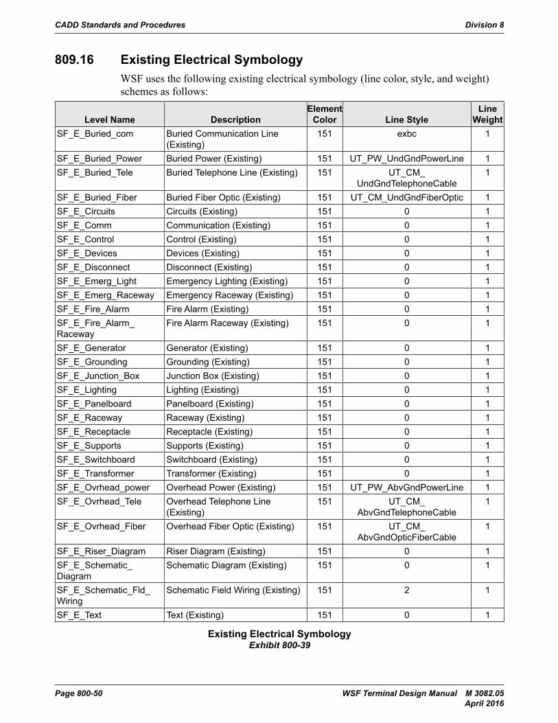
CADD Standards and Procedures Division 8
Page 800-50 WSF Terminal Design Manual M 3082.05 April 2016
809.16 Existing Electrical SymbologyWSF uses the following existing electrical symbology (line color, style, and weight) schemes as follows:
Level Name DescriptionElement
Color Line StyleLine
WeightSF_E_Buried_com Buried Communication Line
(Existing)151 exbc 1
SF_E_Buried_Power Buried Power (Existing) 151 UT_PW_UndGndPowerLine 1SF_E_Buried_Tele Buried Telephone Line (Existing) 151 UT_CM_
UndGndTelephoneCable1
SF_E_Buried_Fiber Buried Fiber Optic (Existing) 151 UT_CM_UndGndFiberOptic 1SF_E_Circuits Circuits (Existing) 151 0 1SF_E_Comm Communication (Existing) 151 0 1SF_E_Control Control (Existing) 151 0 1SF_E_Devices Devices (Existing) 151 0 1SF_E_Disconnect Disconnect (Existing) 151 0 1SF_E_Emerg_Light Emergency Lighting (Existing) 151 0 1SF_E_Emerg_Raceway Emergency Raceway (Existing) 151 0 1SF_E_Fire_Alarm Fire Alarm (Existing) 151 0 1SF_E_Fire_Alarm_Raceway
Fire Alarm Raceway (Existing) 151 0 1
SF_E_Generator Generator (Existing) 151 0 1SF_E_Grounding Grounding (Existing) 151 0 1SF_E_Junction_Box Junction Box (Existing) 151 0 1SF_E_Lighting Lighting (Existing) 151 0 1SF_E_Panelboard Panelboard (Existing) 151 0 1SF_E_Raceway Raceway (Existing) 151 0 1SF_E_Receptacle Receptacle (Existing) 151 0 1SF_E_Supports Supports (Existing) 151 0 1SF_E_Switchboard Switchboard (Existing) 151 0 1SF_E_Transformer Transformer (Existing) 151 0 1SF_E_Ovrhead_power Overhead Power (Existing) 151 UT_PW_AbvGndPowerLine 1SF_E_Ovrhead_Tele Overhead Telephone Line
(Existing)151 UT_CM_
AbvGndTelephoneCable1
SF_E_Ovrhead_Fiber Overhead Fiber Optic (Existing) 151 UT_CM_AbvGndOpticFiberCable
1
SF_E_Riser_Diagram Riser Diagram (Existing) 151 0 1SF_E_Schematic_Diagram
Schematic Diagram (Existing) 151 0 1
SF_E_Schematic_Fld_Wiring
Schematic Field Wiring (Existing) 151 2 1
SF_E_Text Text (Existing) 151 0 1
Existing Electrical SymbologyExhibit 800-39
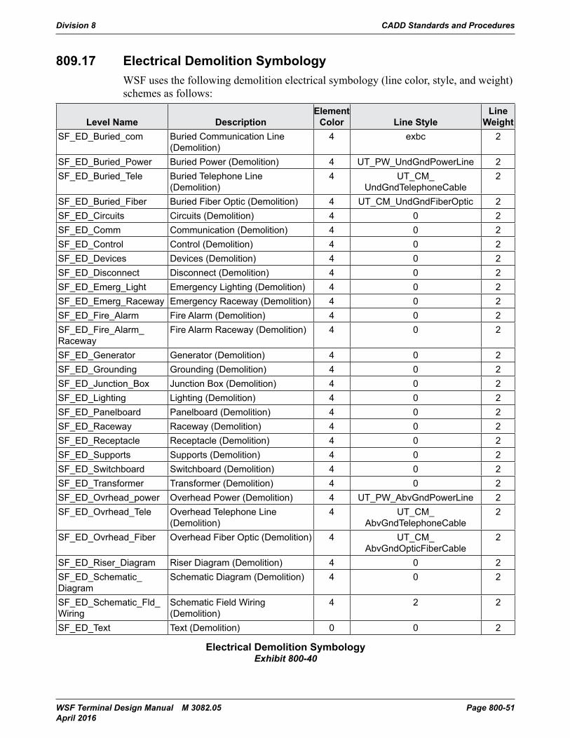
Division 8 CADD Standards and Procedures
WSF Terminal Design Manual M 3082.05 Page 800-51 April 2016
809.17 Electrical Demolition SymbologyWSF uses the following demolition electrical symbology (line color, style, and weight) schemes as follows:
Level Name DescriptionElement
Color Line StyleLine
WeightSF_ED_Buried_com Buried Communication Line
(Demolition)4 exbc 2
SF_ED_Buried_Power Buried Power (Demolition) 4 UT_PW_UndGndPowerLine 2SF_ED_Buried_Tele Buried Telephone Line
(Demolition)4 UT_CM_
UndGndTelephoneCable2
SF_ED_Buried_Fiber Buried Fiber Optic (Demolition) 4 UT_CM_UndGndFiberOptic 2SF_ED_Circuits Circuits (Demolition) 4 0 2SF_ED_Comm Communication (Demolition) 4 0 2SF_ED_Control Control (Demolition) 4 0 2SF_ED_Devices Devices (Demolition) 4 0 2SF_ED_Disconnect Disconnect (Demolition) 4 0 2SF_ED_Emerg_Light Emergency Lighting (Demolition) 4 0 2SF_ED_Emerg_Raceway Emergency Raceway (Demolition) 4 0 2SF_ED_Fire_Alarm Fire Alarm (Demolition) 4 0 2SF_ED_Fire_Alarm_Raceway
Fire Alarm Raceway (Demolition) 4 0 2
SF_ED_Generator Generator (Demolition) 4 0 2SF_ED_Grounding Grounding (Demolition) 4 0 2SF_ED_Junction_Box Junction Box (Demolition) 4 0 2SF_ED_Lighting Lighting (Demolition) 4 0 2SF_ED_Panelboard Panelboard (Demolition) 4 0 2SF_ED_Raceway Raceway (Demolition) 4 0 2SF_ED_Receptacle Receptacle (Demolition) 4 0 2SF_ED_Supports Supports (Demolition) 4 0 2SF_ED_Switchboard Switchboard (Demolition) 4 0 2SF_ED_Transformer Transformer (Demolition) 4 0 2SF_ED_Ovrhead_power Overhead Power (Demolition) 4 UT_PW_AbvGndPowerLine 2SF_ED_Ovrhead_Tele Overhead Telephone Line
(Demolition)4 UT_CM_
AbvGndTelephoneCable2
SF_ED_Ovrhead_Fiber Overhead Fiber Optic (Demolition) 4 UT_CM_AbvGndOpticFiberCable
2
SF_ED_Riser_Diagram Riser Diagram (Demolition) 4 0 2SF_ED_Schematic_Diagram
Schematic Diagram (Demolition) 4 0 2
SF_ED_Schematic_Fld_Wiring
Schematic Field Wiring (Demolition)
4 2 2
SF_ED_Text Text (Demolition) 0 0 2
Electrical Demolition SymbologyExhibit 800-40
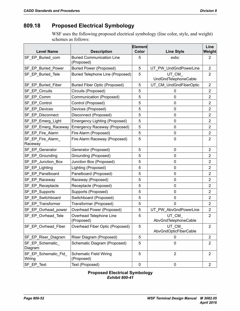
CADD Standards and Procedures Division 8
Page 800-52 WSF Terminal Design Manual M 3082.05 April 2016
809.18 Proposed Electrical SymbologyWSF uses the following proposed electrical symbology (line color, style, and weight) schemes as follows:
Level Name DescriptionElement
Color Line StyleLine
WeightSF_EP_Buried_com Buried Communication Line
(Proposed)5 exbc 2
SF_EP_Buried_Power Buried Power (Proposed) 5 UT_PW_UndGndPowerLine 2SF_EP_Buried_Tele Buried Telephone Line (Proposed) 5 UT_CM_
UndGndTelephoneCable2
SF_EP_Buried_Fiber Buried Fiber Optic (Proposed) 5 UT_CM_UndGndFiberOptic 2SF_EP_Circuits Circuits (Proposed) 5 0 2SF_EP_Comm Communication (Proposed) 5 0 2SF_EP_Control Control (Proposed) 5 0 2SF_EP_Devices Devices (Proposed) 5 0 2SF_EP_Disconnect Disconnect (Proposed) 5 0 2SF_EP_Emerg_Light Emergency Lighting (Proposed) 5 0 2SF_EP_Emerg_Raceway Emergency Raceway (Proposed) 5 0 2SF_EP_Fire_Alarm Fire Alarm (Proposed) 5 0 2SF_EP_Fire_Alarm_Raceway
Fire Alarm Raceway (Proposed) 5 0 2
SF_EP_Generator Generator (Proposed) 5 0 2SF_EP_Grounding Grounding (Proposed) 5 0 2SF_EP_Junction_Box Junction Box (Proposed) 5 0 2SF_EP_Lighting Lighting (Proposed) 5 0 2SF_EP_Panelboard Panelboard (Proposed) 5 0 2SF_EP_Raceway Raceway (Proposed) 5 0 2SF_EP_Receptacle Receptacle (Proposed) 5 0 2SF_EP_Supports Supports (Proposed) 5 0 2SF_EP_Switchboard Switchboard (Proposed) 5 0 2SF_EP_Transformer Transformer (Proposed) 5 0 2SF_EP_Ovrhead_power Overhead Power (Proposed) 5 UT_PW_AbvGndPowerLine 2SF_EP_Ovrhead_Tele Overhead Telephone Line
(Proposed)5 UT_CM_
AbvGndTelephoneCable2
SF_EP_Ovrhead_Fiber Overhead Fiber Optic (Proposed) 5 UT_CM_AbvGndOpticFiberCable
2
SF_EP_Riser_Diagram Riser Diagram (Proposed) 5 0 2SF_EP_Schematic_Diagram
Schematic Diagram (Proposed) 5 0 2
SF_EP_Schematic_Fld_Wiring
Schematic Field Wiring (Proposed)
5 2 2
SF_EP_Text Text (Proposed) 0 0 2
Proposed Electrical SymbologyExhibit 800-41
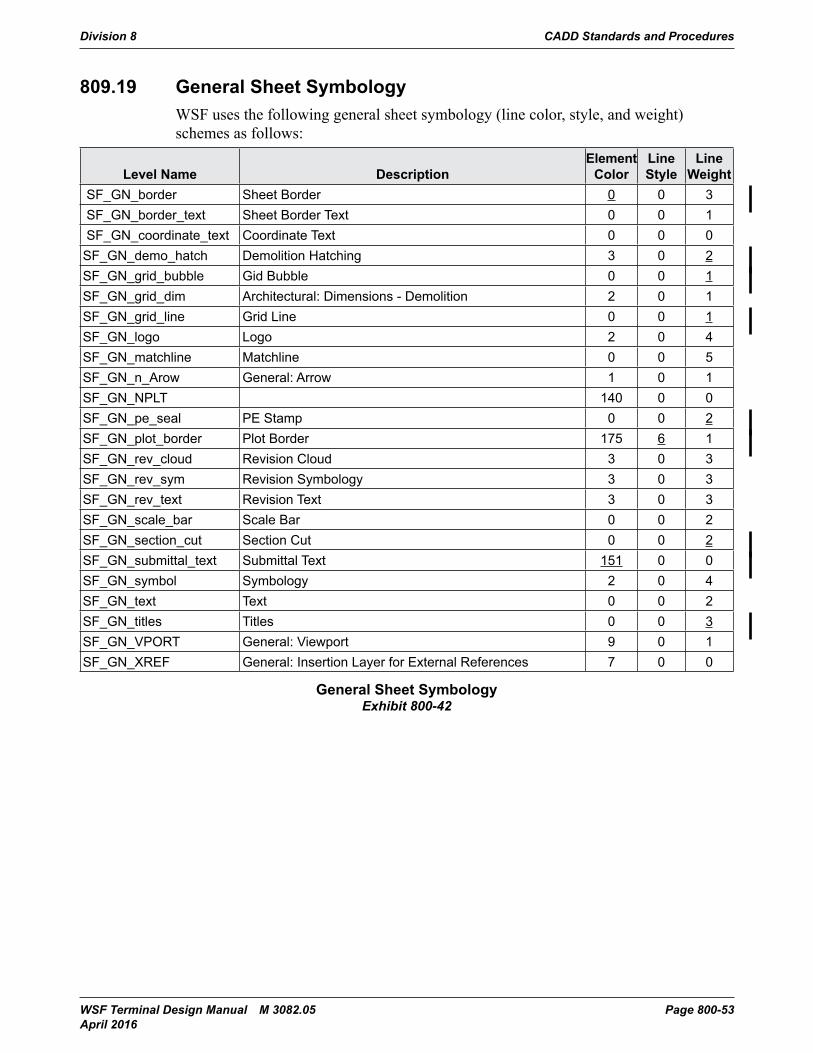
Division 8 CADD Standards and Procedures
WSF Terminal Design Manual M 3082.05 Page 800-53 April 2016
809.19 General Sheet SymbologyWSF uses the following general sheet symbology (line color, style, and weight) schemes as follows:
Level Name DescriptionElement
ColorLine Style
Line Weight
SF_GN_border Sheet Border 0 0 3 SF_GN_border_text Sheet Border Text 0 0 1 SF_GN_coordinate_text Coordinate Text 0 0 0SF_GN_demo_hatch Demolition Hatching 3 0 2SF_GN_grid_bubble Gid Bubble 0 0 1SF_GN_grid_dim Architectural: Dimensions - Demolition 2 0 1SF_GN_grid_line Grid Line 0 0 1SF_GN_logo Logo 2 0 4SF_GN_matchline Matchline 0 0 5SF_GN_n_Arow General: Arrow 1 0 1SF_GN_NPLT 140 0 0SF_GN_pe_seal PE Stamp 0 0 2SF_GN_plot_border Plot Border 175 6 1SF_GN_rev_cloud Revision Cloud 3 0 3SF_GN_rev_sym Revision Symbology 3 0 3SF_GN_rev_text Revision Text 3 0 3SF_GN_scale_bar Scale Bar 0 0 2SF_GN_section_cut Section Cut 0 0 2SF_GN_submittal_text Submittal Text 151 0 0SF_GN_symbol Symbology 2 0 4SF_GN_text Text 0 0 2SF_GN_titles Titles 0 0 3SF_GN_VPORT General: Viewport 9 0 1SF_GN_XREF General: Insertion Layer for External References 7 0 0
General Sheet SymbologyExhibit 800-42
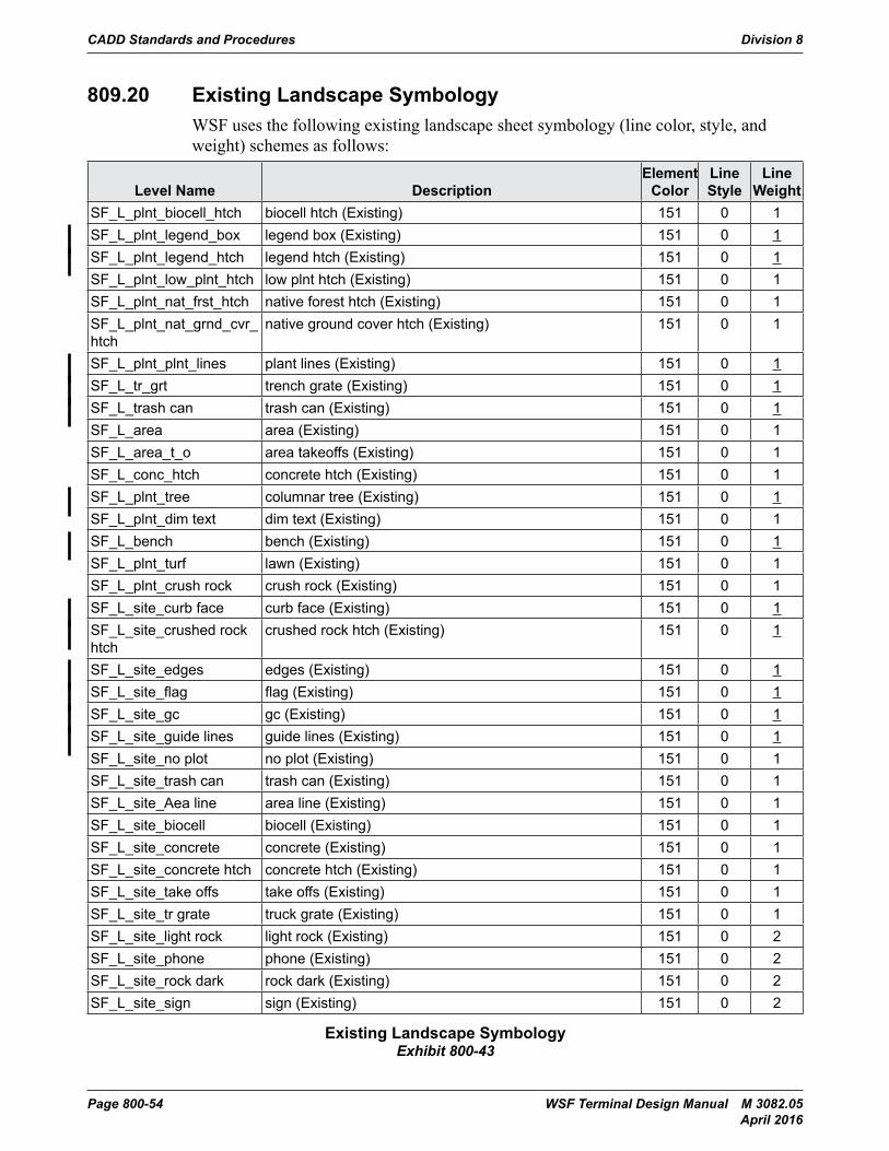
CADD Standards and Procedures Division 8
Page 800-54 WSF Terminal Design Manual M 3082.05 April 2016
809.20 Existing Landscape SymbologyWSF uses the following existing landscape sheet symbology (line color, style, and weight) schemes as follows:
Level Name DescriptionElement
ColorLine Style
Line Weight
SF_L_plnt_biocell_htch biocell htch (Existing) 151 0 1SF_L_plnt_legend_box legend box (Existing) 151 0 1SF_L_plnt_legend_htch legend htch (Existing) 151 0 1SF_L_plnt_low_plnt_htch low plnt htch (Existing) 151 0 1SF_L_plnt_nat_frst_htch native forest htch (Existing) 151 0 1SF_L_plnt_nat_grnd_cvr_htch
native ground cover htch (Existing) 151 0 1
SF_L_plnt_plnt_lines plant lines (Existing) 151 0 1SF_L_tr_grt trench grate (Existing) 151 0 1SF_L_trash can trash can (Existing) 151 0 1SF_L_area area (Existing) 151 0 1SF_L_area_t_o area takeoffs (Existing) 151 0 1SF_L_conc_htch concrete htch (Existing) 151 0 1SF_L_plnt_tree columnar tree (Existing) 151 0 1SF_L_plnt_dim text dim text (Existing) 151 0 1SF_L_bench bench (Existing) 151 0 1SF_L_plnt_turf lawn (Existing) 151 0 1SF_L_plnt_crush rock crush rock (Existing) 151 0 1SF_L_site_curb face curb face (Existing) 151 0 1SF_L_site_crushed rock htch
crushed rock htch (Existing) 151 0 1
SF_L_site_edges edges (Existing) 151 0 1SF_L_site_flag flag (Existing) 151 0 1SF_L_site_gc gc (Existing) 151 0 1SF_L_site_guide lines guide lines (Existing) 151 0 1SF_L_site_no plot no plot (Existing) 151 0 1SF_L_site_trash can trash can (Existing) 151 0 1SF_L_site_Aea line area line (Existing) 151 0 1SF_L_site_biocell biocell (Existing) 151 0 1SF_L_site_concrete concrete (Existing) 151 0 1SF_L_site_concrete htch concrete htch (Existing) 151 0 1SF_L_site_take offs take offs (Existing) 151 0 1SF_L_site_tr grate truck grate (Existing) 151 0 1SF_L_site_light rock light rock (Existing) 151 0 2SF_L_site_phone phone (Existing) 151 0 2SF_L_site_rock dark rock dark (Existing) 151 0 2SF_L_site_sign sign (Existing) 151 0 2
Existing Landscape SymbologyExhibit 800-43
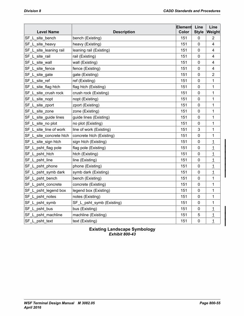
Division 8 CADD Standards and Procedures
WSF Terminal Design Manual M 3082.05 Page 800-55 April 2016
Level Name DescriptionElement
ColorLine Style
Line Weight
SF_L_site_bench bench (Existing) 151 0 2SF_L_site_heavy heavy (Existing) 151 0 4SF_L_site_leaning rail leaning rail (Existing) 151 0 4SF_L_site_rail rail (Existing) 151 0 4SF_L_site_wall wall (Existing) 151 0 4SF_L_site_fence fence (Existing) 151 0 4SF_L_site_gate gate (Existing) 151 0 2SF_L_site_ref ref (Existing) 151 0 1SF_L_site_flag htch flag htch (Existing) 151 0 1SF_L_site_crush rock crush rock (Existing) 151 0 1SF_L_site_nopt nopt (Existing) 151 0 1SF_L_site_zport zport (Existing) 151 0 1SF_L_site_zone zone (Existing) 151 0 1SF_L_site_guide lines guide lines (Existing) 151 0 1SF_L_site_no plot no plot (Existing) 151 0 1SF_L_site_line of work line of work (Existing) 151 3 1SF_L_site_concrete htch concrete htch (Existing) 151 0 1SF_L_site_sign htch sign htch (Existing) 151 0 1SF_L_psht_flag pole flag pole (Existing) 151 0 1SF_L_psht_htch htch (Existing) 151 0 1SF_L_psht_line line (Existing) 151 0 1SF_L_psht_phone phone (Existing) 151 0 1SF_L_psht_symb dark symb dark (Existing) 151 0 1SF_L_psht_bench bench (Existing) 151 0 1SF_L_psht_concrete concrete (Existing) 151 0 1SF_L_psht_legend box legend box (Existing) 151 0 1SF_L_psht_notes notes (Existing) 151 0 1SF_L_psht_symb SF_L_psht_symb (Existing) 151 0 1SF_L_psht_bus bus (Existing) 151 0 1SF_L_psht_machline machline (Existing) 151 5 1SF_L_psht_text text (Existing) 151 0 1
Existing Landscape SymbologyExhibit 800-43
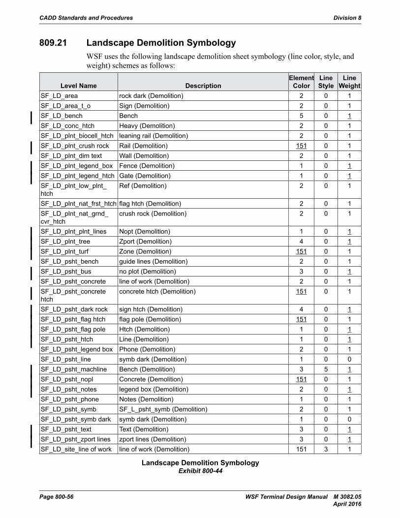
CADD Standards and Procedures Division 8
Page 800-56 WSF Terminal Design Manual M 3082.05 April 2016
809.21 Landscape Demolition SymbologyWSF uses the following landscape demolition sheet symbology (line color, style, and weight) schemes as follows:
Level Name DescriptionElement
ColorLine Style
Line Weight
SF_LD_area rock dark (Demolition) 2 0 1SF_LD_area_t_o Sign (Demolition) 2 0 1SF_LD_bench Bench 5 0 1SF_LD_conc_htch Heavy (Demolition) 2 0 1SF_LD_plnt_biocell_htch leaning rail (Demolition) 2 0 1SF_LD_plnt_crush rock Rail (Demolition) 151 0 1SF_LD_plnt_dim text Wall (Demolition) 2 0 1SF_LD_plnt_legend_box Fence (Demolition) 1 0 1SF_LD_plnt_legend_htch Gate (Demolition) 1 0 1SF_LD_plnt_low_plnt_htch
Ref (Demolition) 2 0 1
SF_LD_plnt_nat_frst_htch flag htch (Demolition) 2 0 1SF_LD_plnt_nat_grnd_cvr_htch
crush rock (Demolition) 2 0 1
SF_LD_plnt_plnt_lines Nopt (Demolition) 1 0 1SF_LD_plnt_tree Zport (Demolition) 4 0 1SF_LD_plnt_turf Zone (Demolition) 151 0 1SF_LD_psht_bench guide lines (Demolition) 2 0 1SF_LD_psht_bus no plot (Demolition) 3 0 1SF_LD_psht_concrete line of work (Demolition) 2 0 1SF_LD_psht_concrete htch
concrete htch (Demolition) 151 0 1
SF_LD_psht_dark rock sign htch (Demolition) 4 0 1SF_LD_psht_flag htch flag pole (Demolition) 151 0 1SF_LD_psht_flag pole Htch (Demolition) 1 0 1SF_LD_psht_htch Line (Demolition) 1 0 1SF_LD_psht_legend box Phone (Demolition) 2 0 1SF_LD_psht_line symb dark (Demolition) 1 0 0SF_LD_psht_machline Bench (Demolition) 3 5 1SF_LD_psht_nopl Concrete (Demolition) 151 0 1SF_LD_psht_notes legend box (Demolition) 2 0 1SF_LD_psht_phone Notes (Demolition) 1 0 1SF_LD_psht_symb SF_L_psht_symb (Demolition) 2 0 1SF_LD_psht_symb dark symb dark (Demolition) 1 0 0SF_LD_psht_text Text (Demolition) 3 0 1SF_LD_psht_zport lines zport lines (Demolition) 3 0 1SF_LD_site_line of work line of work (Demolition) 151 3 1
Landscape Demolition SymbologyExhibit 800-44
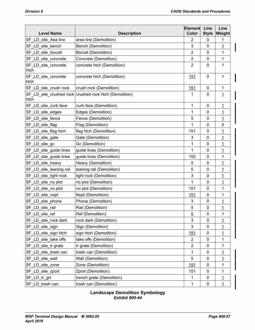
Division 8 CADD Standards and Procedures
WSF Terminal Design Manual M 3082.05 Page 800-57 April 2016
Level Name DescriptionElement
ColorLine Style
Line Weight
SF_LD_site_Aea line area line (Demolition) 2 0 1SF_LD_site_bench Bench (Demolition) 3 0 1SF_LD_site_biocell Biocell (Demolition) 2 0 1SF_LD_site_concrete Concrete (Demolition) 2 0 1SF_LD_site_concrete htch
concrete htch (Demolition) 2 0 1
SF_LD_site_concrete htch
concrete htch (Demolition) 151 0 1
SF_LD_site_crush rock crush rock (Demolition) 151 0 1SF_LD_site_crushed rock htch
crushed rock htch (Demolition) 1 0 1
SF_LD_site_curb face curb face (Demolition) 1 0 1SF_LD_site_edges Edges (Demolition) 1 0 1SF_LD_site_fence Fence (Demolition) 5 0 1SF_LD_site_flag Flag (Demolition) 1 0 0SF_LD_site_flag htch flag htch (Demolition) 151 0 1SF_LD_site_gate Gate (Demolition) 3 0 1SF_LD_site_gc Gc (Demolition) 1 0 1SF_LD_site_guide lines guide lines (Demolition) 1 0 1SF_LD_site_guide lines guide lines (Demolition) 152 0 1SF_LD_site_heavy Heavy (Demolition) 5 0 1SF_LD_site_leaning rail leaning rail (Demolition) 5 0 1SF_LD_site_light rock light rock (Demolition) 3 0 1SF_LD_site_no plot no plot (Demolition) 1 0 1SF_LD_site_no plot no plot (Demolition) 151 0 1SF_LD_site_nopt Nopt (Demolition) 151 0 1SF_LD_site_phone Phone (Demolition) 3 0 1SF_LD_site_rail Rail (Demolition) 5 0 1SF_LD_site_ref Ref (Demolition) 5 0 1SF_LD_site_rock dark rock dark (Demolition) 3 0 1SF_LD_site_sign Sign (Demolition) 3 0 1SF_LD_site_sign htch sign htch (Demolition) 151 0 1SF_LD_site_take offs take offs (Demolition) 2 0 1SF_LD_site_tr grate tr grate (Demolition) 2 0 1SF_LD_site_trash can trash can (Demolition) 1 0 1SF_LD_site_wall Wall (Demolition) 5 0 1SF_LD_site_zone Zone (Demolition) 151 0 1SF_LD_site_zport Zport (Demolition) 151 0 1SF_LD_tr_grt trench grate (Demolition) 1 0 1SF_LD_trash can trash can (Demolition) 1 0 1
Landscape Demolition SymbologyExhibit 800-44
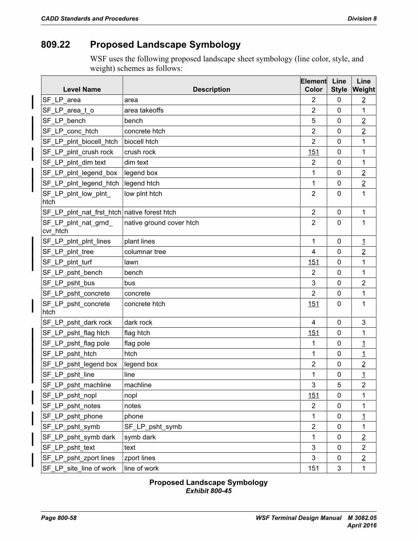
CADD Standards and Procedures Division 8
Page 800-58 WSF Terminal Design Manual M 3082.05 April 2016
809.22 Proposed Landscape SymbologyWSF uses the following proposed landscape sheet symbology (line color, style, and weight) schemes as follows:
Level Name DescriptionElement
ColorLine Style
Line Weight
SF_LP_area area 2 0 2SF_LP_area_t_o area takeoffs 2 0 1SF_LP_bench bench 5 0 2SF_LP_conc_htch concrete htch 2 0 2SF_LP_plnt_biocell_htch biocell htch 2 0 1SF_LP_plnt_crush rock crush rock 151 0 1SF_LP_plnt_dim text dim text 2 0 1SF_LP_plnt_legend_box legend box 1 0 2SF_LP_plnt_legend_htch legend htch 1 0 2SF_LP_plnt_low_plnt_htch
low plnt htch 2 0 1
SF_LP_plnt_nat_frst_htch native forest htch 2 0 1SF_LP_plnt_nat_grnd_cvr_htch
native ground cover htch 2 0 1
SF_LP_plnt_plnt_lines plant lines 1 0 1SF_LP_plnt_tree columnar tree 4 0 2SF_LP_plnt_turf lawn 151 0 1SF_LP_psht_bench bench 2 0 1SF_LP_psht_bus bus 3 0 2SF_LP_psht_concrete concrete 2 0 1SF_LP_psht_concrete htch
concrete htch 151 0 1
SF_LP_psht_dark rock dark rock 4 0 3SF_LP_psht_flag htch flag htch 151 0 1SF_LP_psht_flag pole flag pole 1 0 1SF_LP_psht_htch htch 1 0 1SF_LP_psht_legend box legend box 2 0 2SF_LP_psht_line line 1 0 1SF_LP_psht_machline machline 3 5 2SF_LP_psht_nopl nopl 151 0 1SF_LP_psht_notes notes 2 0 1SF_LP_psht_phone phone 1 0 1SF_LP_psht_symb SF_LP_psht_symb 2 0 1SF_LP_psht_symb dark symb dark 1 0 2SF_LP_psht_text text 3 0 2SF_LP_psht_zport lines zport lines 3 0 2SF_LP_site_line of work line of work 151 3 1
Proposed Landscape SymbologyExhibit 800-45
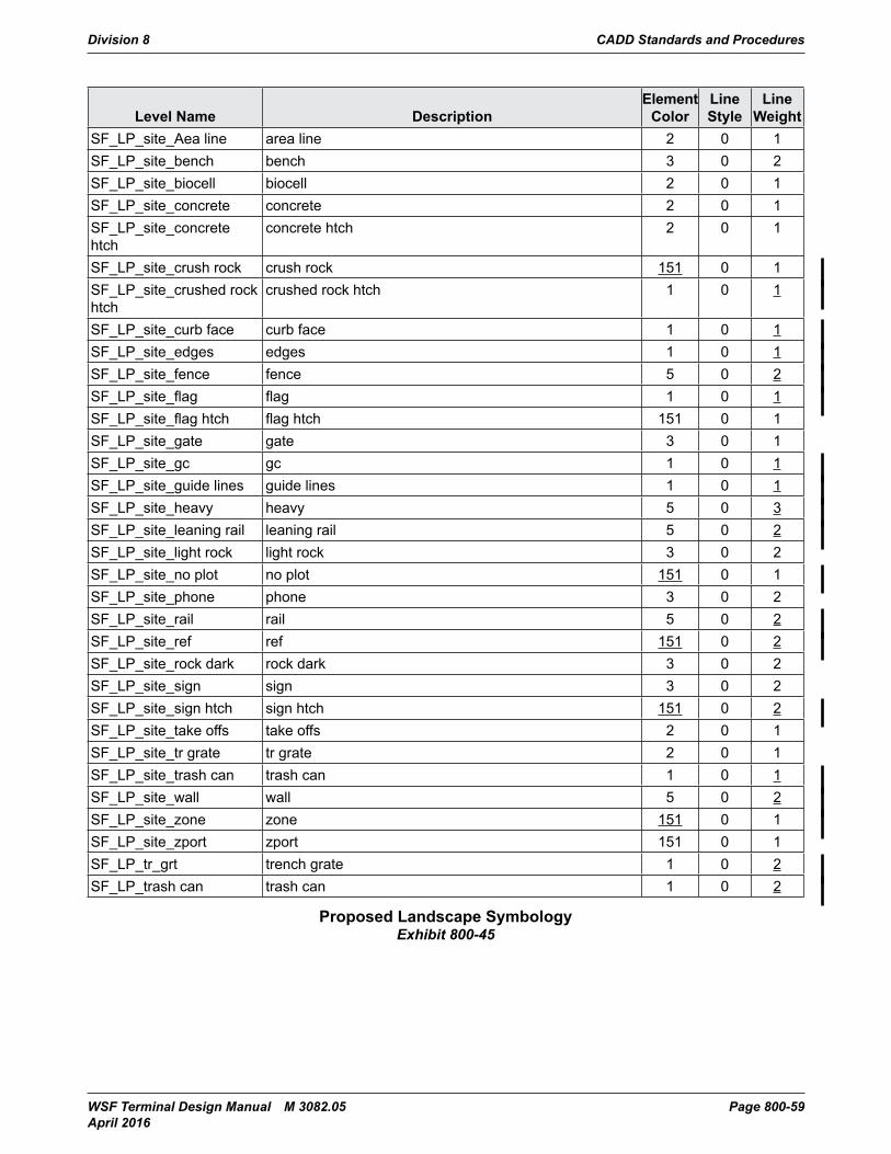
Division 8 CADD Standards and Procedures
WSF Terminal Design Manual M 3082.05 Page 800-59 April 2016
Level Name DescriptionElement
ColorLine Style
Line Weight
SF_LP_site_Aea line area line 2 0 1SF_LP_site_bench bench 3 0 2SF_LP_site_biocell biocell 2 0 1SF_LP_site_concrete concrete 2 0 1SF_LP_site_concrete htch
concrete htch 2 0 1
SF_LP_site_crush rock crush rock 151 0 1SF_LP_site_crushed rock htch
crushed rock htch 1 0 1
SF_LP_site_curb face curb face 1 0 1SF_LP_site_edges edges 1 0 1SF_LP_site_fence fence 5 0 2SF_LP_site_flag flag 1 0 1SF_LP_site_flag htch flag htch 151 0 1SF_LP_site_gate gate 3 0 1SF_LP_site_gc gc 1 0 1SF_LP_site_guide lines guide lines 1 0 1SF_LP_site_heavy heavy 5 0 3SF_LP_site_leaning rail leaning rail 5 0 2SF_LP_site_light rock light rock 3 0 2SF_LP_site_no plot no plot 151 0 1SF_LP_site_phone phone 3 0 2SF_LP_site_rail rail 5 0 2SF_LP_site_ref ref 151 0 2SF_LP_site_rock dark rock dark 3 0 2SF_LP_site_sign sign 3 0 2SF_LP_site_sign htch sign htch 151 0 2SF_LP_site_take offs take offs 2 0 1SF_LP_site_tr grate tr grate 2 0 1SF_LP_site_trash can trash can 1 0 1SF_LP_site_wall wall 5 0 2SF_LP_site_zone zone 151 0 1SF_LP_site_zport zport 151 0 1SF_LP_tr_grt trench grate 1 0 2SF_LP_trash can trash can 1 0 2
Proposed Landscape SymbologyExhibit 800-45
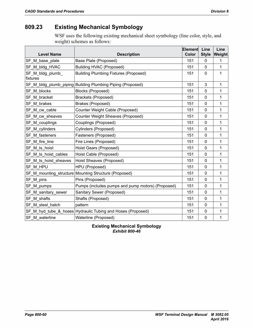
CADD Standards and Procedures Division 8
Page 800-60 WSF Terminal Design Manual M 3082.05 April 2016
809.23 Existing Mechanical SymbologyWSF uses the following existing mechanical sheet symbology (line color, style, and weight) schemes as follows:
Level Name DescriptionElement
ColorLine Style
Line Weight
SF_M_base_plate Base Plate (Proposed) 151 0 1SF_M_bldg_HVAC Building HVAC (Proposed) 151 0 1SF_M_bldg_plumb_fixtures
Building Plumbing Fixtures (Proposed) 151 0 1
SF_M_bldg_plumb_piping Building Plumbing Piping (Proposed) 151 3 1SF_M_blocks Blocks (Proposed) 151 0 1SF_M_bracket Brackets (Proposed) 151 0 1SF_M_brakes Brakes (Proposed) 151 0 1SF_M_cw_cable Counter Weight Cable (Proposed) 151 0 1SF_M_cw_sheaves Counter Weight Sheaves (Proposed) 151 0 1SF_M_couplings Couplings (Proposed) 151 0 1SF_M_cylinders Cylinders (Proposed) 151 0 1SF_M_fasteners Fasteners (Proposed) 151 0 1SF_M_fire_line Fire Lines (Proposed) 151 0 1SF_M_ts_hoist Hoist Gears (Proposed) 151 0 1SF_M_ts_hoist_cables Hoist Cable (Proposed) 151 0 1SF_M_ts_hoist_sheaves Hoist Sheaves (Proposed) 151 0 1SF_M_HPU HPU (Proposed) 151 0 1SF_M_mounting_structure Mounting Structure (Proposed) 151 0 1SF_M_pins Pins (Proposed) 151 0 1SF_M_pumps Pumps (includes pumps and pump motors) (Proposed) 151 0 1SF_M_sanitary_sewer Sanitary Sewer (Proposed) 151 0 1SF_M_shafts Shafts (Proposed) 151 0 1SF_M_steel_hatch pattern 151 0 1SF_M_hyd_tube_&_hoses Hydraulic Tubing and Hoses (Proposed) 151 0 1SF_M_waterline Waterline (Proposed) 151 0 1
Existing Mechanical SymbologyExhibit 800-46
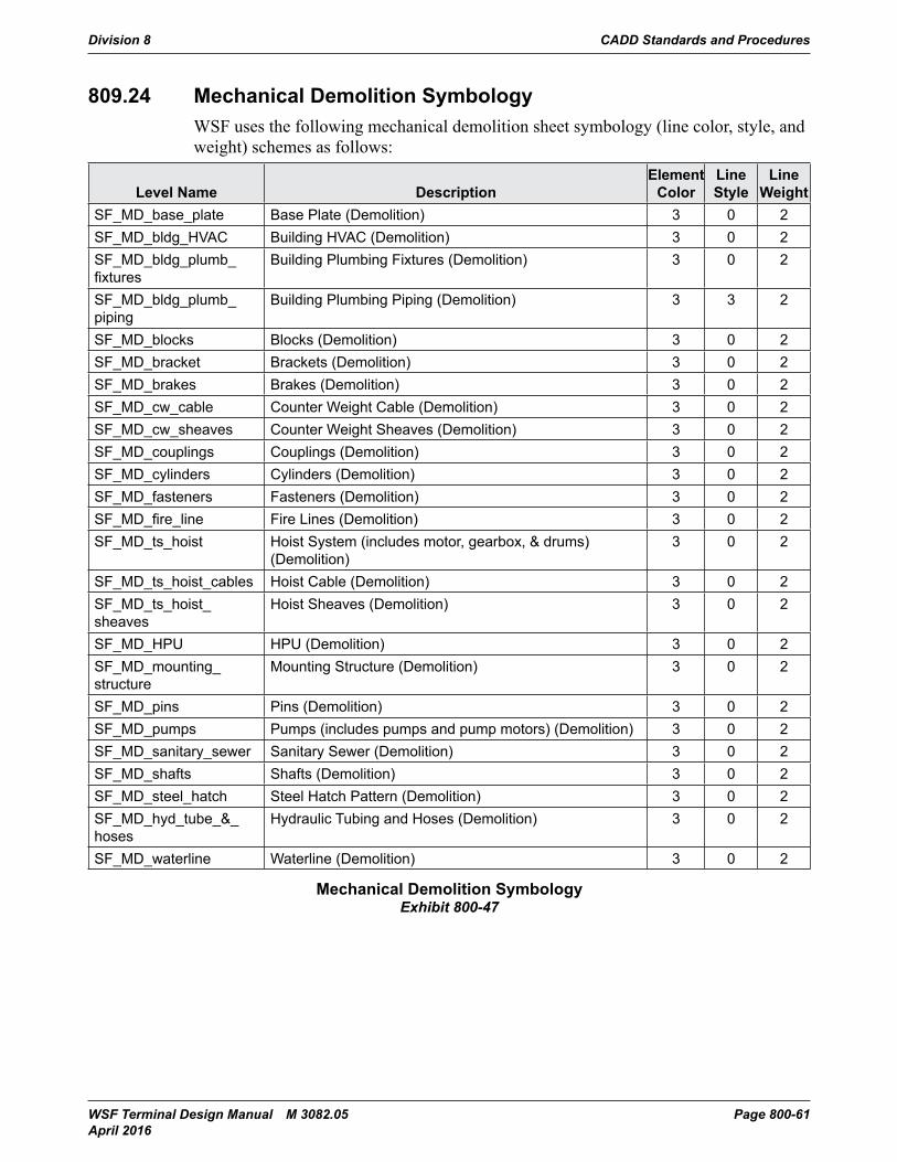
Division 8 CADD Standards and Procedures
WSF Terminal Design Manual M 3082.05 Page 800-61 April 2016
809.24 Mechanical Demolition SymbologyWSF uses the following mechanical demolition sheet symbology (line color, style, and weight) schemes as follows:
Level Name DescriptionElement
ColorLine Style
Line Weight
SF_MD_base_plate Base Plate (Demolition) 3 0 2SF_MD_bldg_HVAC Building HVAC (Demolition) 3 0 2SF_MD_bldg_plumb_fixtures
Building Plumbing Fixtures (Demolition) 3 0 2
SF_MD_bldg_plumb_piping
Building Plumbing Piping (Demolition) 3 3 2
SF_MD_blocks Blocks (Demolition) 3 0 2SF_MD_bracket Brackets (Demolition) 3 0 2SF_MD_brakes Brakes (Demolition) 3 0 2SF_MD_cw_cable Counter Weight Cable (Demolition) 3 0 2SF_MD_cw_sheaves Counter Weight Sheaves (Demolition) 3 0 2SF_MD_couplings Couplings (Demolition) 3 0 2SF_MD_cylinders Cylinders (Demolition) 3 0 2SF_MD_fasteners Fasteners (Demolition) 3 0 2SF_MD_fire_line Fire Lines (Demolition) 3 0 2SF_MD_ts_hoist Hoist System (includes motor, gearbox, & drums)
(Demolition)3 0 2
SF_MD_ts_hoist_cables Hoist Cable (Demolition) 3 0 2SF_MD_ts_hoist_sheaves
Hoist Sheaves (Demolition) 3 0 2
SF_MD_HPU HPU (Demolition) 3 0 2SF_MD_mounting_structure
Mounting Structure (Demolition) 3 0 2
SF_MD_pins Pins (Demolition) 3 0 2SF_MD_pumps Pumps (includes pumps and pump motors) (Demolition) 3 0 2SF_MD_sanitary_sewer Sanitary Sewer (Demolition) 3 0 2SF_MD_shafts Shafts (Demolition) 3 0 2SF_MD_steel_hatch Steel Hatch Pattern (Demolition) 3 0 2SF_MD_hyd_tube_&_hoses
Hydraulic Tubing and Hoses (Demolition) 3 0 2
SF_MD_waterline Waterline (Demolition) 3 0 2
Mechanical Demolition SymbologyExhibit 800-47
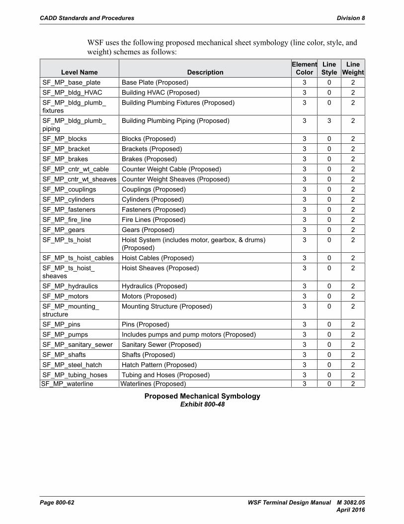
CADD Standards and Procedures Division 8
Page 800-62 WSF Terminal Design Manual M 3082.05 April 2016
WSF uses the following proposed mechanical sheet symbology (line color, style, and weight) schemes as follows:
Level Name DescriptionElement
ColorLine Style
Line Weight
SF_MP_base_plate Base Plate (Proposed) 3 0 2SF_MP_bldg_HVAC Building HVAC (Proposed) 3 0 2SF_MP_bldg_plumb_fixtures
Building Plumbing Fixtures (Proposed) 3 0 2
SF_MP_bldg_plumb_piping
Building Plumbing Piping (Proposed) 3 3 2
SF_MP_blocks Blocks (Proposed) 3 0 2SF_MP_bracket Brackets (Proposed) 3 0 2SF_MP_brakes Brakes (Proposed) 3 0 2SF_MP_cntr_wt_cable Counter Weight Cable (Proposed) 3 0 2SF_MP_cntr_wt_sheaves Counter Weight Sheaves (Proposed) 3 0 2SF_MP_couplings Couplings (Proposed) 3 0 2SF_MP_cylinders Cylinders (Proposed) 3 0 2SF_MP_fasteners Fasteners (Proposed) 3 0 2SF_MP_fire_line Fire Lines (Proposed) 3 0 2SF_MP_gears Gears (Proposed) 3 0 2SF_MP_ts_hoist Hoist System (includes motor, gearbox, & drums)
(Proposed)3 0 2
SF_MP_ts_hoist_cables Hoist Cables (Proposed) 3 0 2SF_MP_ts_hoist_sheaves
Hoist Sheaves (Proposed) 3 0 2
SF_MP_hydraulics Hydraulics (Proposed) 3 0 2SF_MP_motors Motors (Proposed) 3 0 2SF_MP_mounting_structure
Mounting Structure (Proposed) 3 0 2
SF_MP_pins Pins (Proposed) 3 0 2SF_MP_pumps Includes pumps and pump motors (Proposed) 3 0 2SF_MP_sanitary_sewer Sanitary Sewer (Proposed) 3 0 2SF_MP_shafts Shafts (Proposed) 3 0 2SF_MP_steel_hatch Hatch Pattern (Proposed) 3 0 2SF_MP_tubing_hoses Tubing and Hoses (Proposed) 3 0 2SF_MP_waterline Waterlines (Proposed) 3 0 2
Proposed Mechanical SymbologyExhibit 800-48
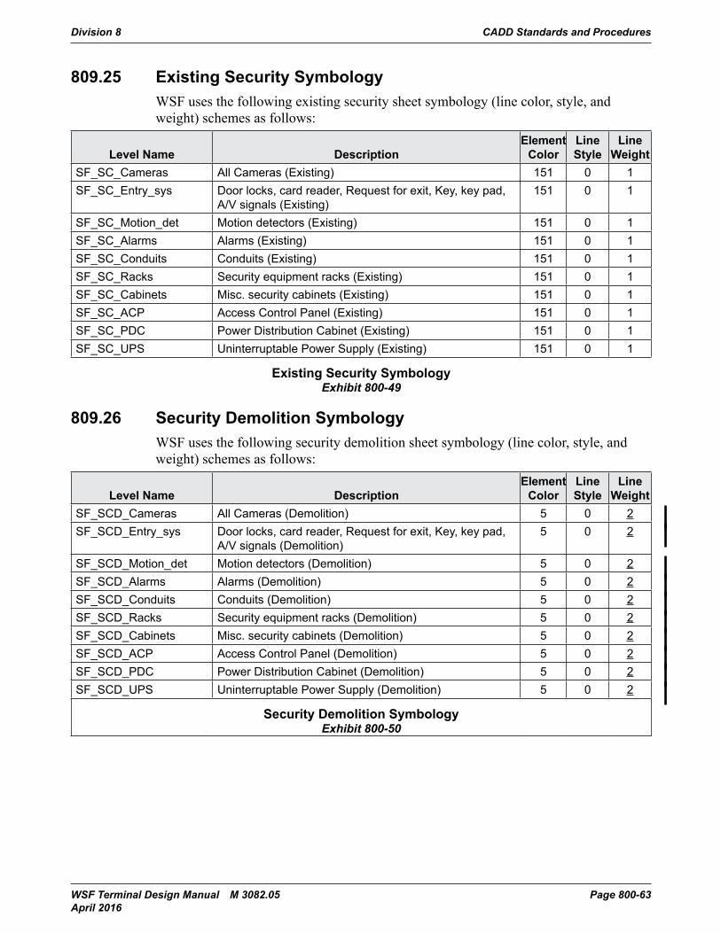
Division 8 CADD Standards and Procedures
WSF Terminal Design Manual M 3082.05 Page 800-63 April 2016
809.25 Existing Security SymbologyWSF uses the following existing security sheet symbology (line color, style, and weight) schemes as follows:
Level Name DescriptionElement
ColorLine Style
Line Weight
SF_SC_Cameras All Cameras (Existing) 151 0 1SF_SC_Entry_sys Door locks, card reader, Request for exit, Key, key pad,
A/V signals (Existing)151 0 1
SF_SC_Motion_det Motion detectors (Existing) 151 0 1SF_SC_Alarms Alarms (Existing) 151 0 1SF_SC_Conduits Conduits (Existing) 151 0 1SF_SC_Racks Security equipment racks (Existing) 151 0 1SF_SC_Cabinets Misc. security cabinets (Existing) 151 0 1SF_SC_ACP Access Control Panel (Existing) 151 0 1SF_SC_PDC Power Distribution Cabinet (Existing) 151 0 1SF_SC_UPS Uninterruptable Power Supply (Existing) 151 0 1
Existing Security SymbologyExhibit 800-49
809.26 Security Demolition SymbologyWSF uses the following security demolition sheet symbology (line color, style, and weight) schemes as follows:
Level Name DescriptionElement
ColorLine Style
Line Weight
SF_SCD_Cameras All Cameras (Demolition) 5 0 2SF_SCD_Entry_sys Door locks, card reader, Request for exit, Key, key pad,
A/V signals (Demolition)5 0 2
SF_SCD_Motion_det Motion detectors (Demolition) 5 0 2SF_SCD_Alarms Alarms (Demolition) 5 0 2SF_SCD_Conduits Conduits (Demolition) 5 0 2SF_SCD_Racks Security equipment racks (Demolition) 5 0 2SF_SCD_Cabinets Misc. security cabinets (Demolition) 5 0 2SF_SCD_ACP Access Control Panel (Demolition) 5 0 2SF_SCD_PDC Power Distribution Cabinet (Demolition) 5 0 2SF_SCD_UPS Uninterruptable Power Supply (Demolition) 5 0 2
Security Demolition SymbologyExhibit 800-50
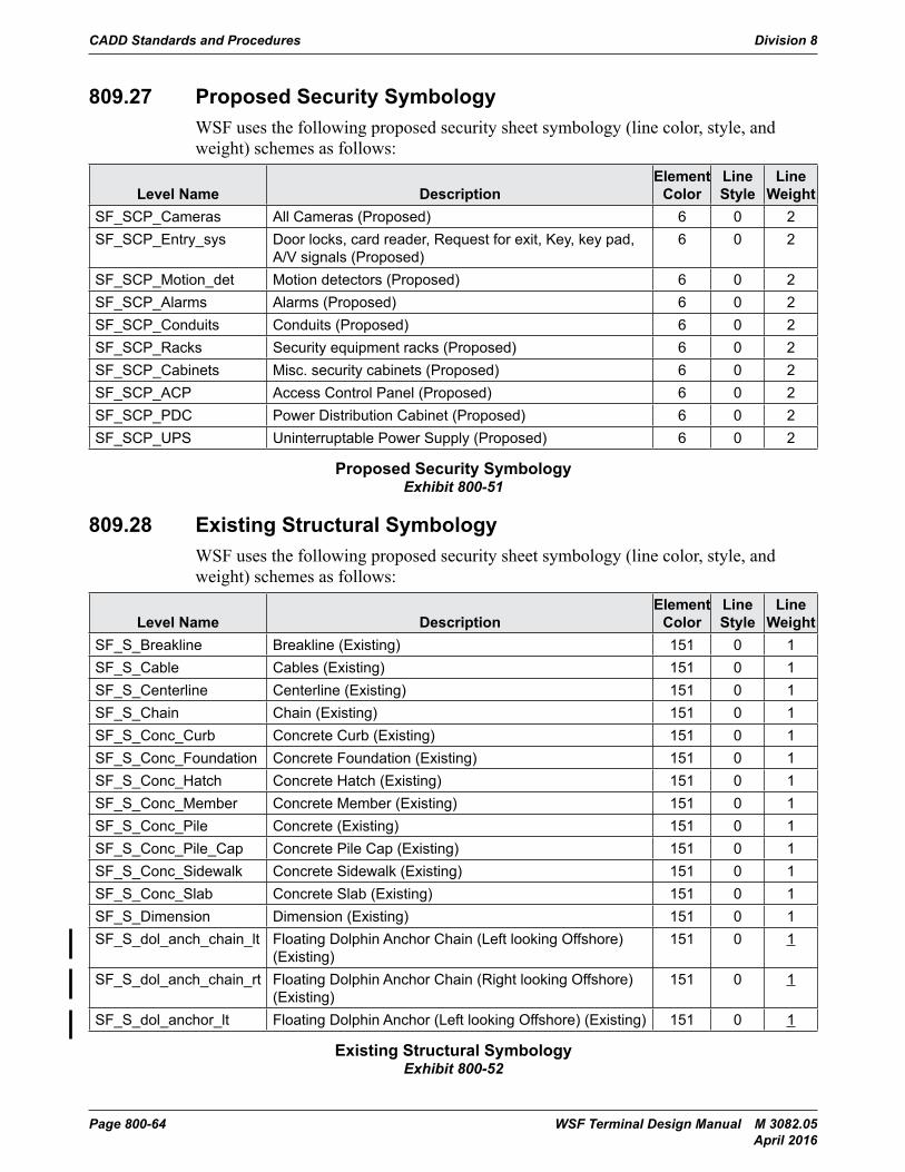
CADD Standards and Procedures Division 8
Page 800-64 WSF Terminal Design Manual M 3082.05 April 2016
809.27 Proposed Security SymbologyWSF uses the following proposed security sheet symbology (line color, style, and weight) schemes as follows:
Level Name DescriptionElement
ColorLine Style
Line Weight
SF_SCP_Cameras All Cameras (Proposed) 6 0 2SF_SCP_Entry_sys Door locks, card reader, Request for exit, Key, key pad,
A/V signals (Proposed)6 0 2
SF_SCP_Motion_det Motion detectors (Proposed) 6 0 2SF_SCP_Alarms Alarms (Proposed) 6 0 2SF_SCP_Conduits Conduits (Proposed) 6 0 2SF_SCP_Racks Security equipment racks (Proposed) 6 0 2SF_SCP_Cabinets Misc. security cabinets (Proposed) 6 0 2SF_SCP_ACP Access Control Panel (Proposed) 6 0 2SF_SCP_PDC Power Distribution Cabinet (Proposed) 6 0 2SF_SCP_UPS Uninterruptable Power Supply (Proposed) 6 0 2
Proposed Security SymbologyExhibit 800-51
809.28 Existing Structural SymbologyWSF uses the following proposed security sheet symbology (line color, style, and weight) schemes as follows:
Level Name DescriptionElement
ColorLine Style
Line Weight
SF_S_Breakline Breakline (Existing) 151 0 1SF_S_Cable Cables (Existing) 151 0 1SF_S_Centerline Centerline (Existing) 151 0 1SF_S_Chain Chain (Existing) 151 0 1SF_S_Conc_Curb Concrete Curb (Existing) 151 0 1SF_S_Conc_Foundation Concrete Foundation (Existing) 151 0 1SF_S_Conc_Hatch Concrete Hatch (Existing) 151 0 1SF_S_Conc_Member Concrete Member (Existing) 151 0 1SF_S_Conc_Pile Concrete (Existing) 151 0 1SF_S_Conc_Pile_Cap Concrete Pile Cap (Existing) 151 0 1SF_S_Conc_Sidewalk Concrete Sidewalk (Existing) 151 0 1SF_S_Conc_Slab Concrete Slab (Existing) 151 0 1SF_S_Dimension Dimension (Existing) 151 0 1SF_S_dol_anch_chain_lt Floating Dolphin Anchor Chain (Left looking Offshore)
(Existing)151 0 1
SF_S_dol_anch_chain_rt Floating Dolphin Anchor Chain (Right looking Offshore) (Existing)
151 0 1
SF_S_dol_anchor_lt Floating Dolphin Anchor (Left looking Offshore) (Existing) 151 0 1
Existing Structural SymbologyExhibit 800-52
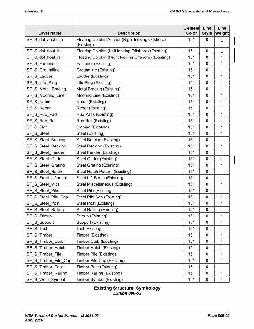
Division 8 CADD Standards and Procedures
WSF Terminal Design Manual M 3082.05 Page 800-65 April 2016
Level Name DescriptionElement
ColorLine Style
Line Weight
SF_S_dol_anchor_rt Floating Dolphin Anchor (Right looking Offshore) (Existing)
151 0 1
SF_S_dol_float_lt Floating Dolphin (Left looking Offshore) (Existing) 151 0 1SF_S_dol_float_rt Floating Dolphin (Right looking Offshore) (Existing) 151 0 1SF_S_Fastener Fastener (Existing) 151 0 1SF_S_Groundline Groundline (Existing) 151 0 1SF_S_Ladder Ladder (Existing) 151 0 1SF_S_Life_Ring Life Ring (Existing) 151 0 1SF_S_Metal_Bracing Metal Bracing (Existing) 151 0 1SF_S_Mooring_Line Mooring Line (Existing) 151 0 1SF_S_Notes Notes (Existing) 151 0 1SF_S_Rebar Rebar (Existing) 151 0 1SF_S_Rub_Pad Rub Pads (Existing) 151 0 1SF_S_Rub_Rail Rub Rail (Existing) 151 0 1SF_S_Sign Signing (Existing) 151 0 1SF_S_Steel Steel (Existing) 151 0 1SF_S_Steel_Bracing Steel Bracing (Existing) 151 0 1SF_S_Steel_Decking Steel Decking (Existing) 151 0 1SF_S_Steel_Fender Steel Fender (Existing) 151 0 1SF_S_Steel_Girder Steel Girder (Existing) 151 0 1SF_S_Steel_Grating Steel Grating (Existing) 151 0 1SF_S_Steel_Hatch Steel Hatch Pattern (Existing) 151 0 1SF_S_Steel_Liftbeam Steel Lift Beam (Existing) 151 0 1SF_S_Steel_Mics Steel Miscellaneous (Existing) 151 0 1SF_S_Steel_Pile Steel Pile (Existing) 151 0 1SF_S_Steel_Pile_Cap Steel Pile Cap (Existing) 151 0 1SF_S_Steel_Post Steel Post (Existing) 151 0 1SF_S_Steel_Railing Steel Railing (Existing) 151 0 1SF_S_Stirrup Stirrup (Existing) 151 0 1SF_S_Support Support (Existing) 151 0 1SF_S_Text Text (Existing) 151 0 1SF_S_Timber Timber (Existing) 151 0 1SF_S_Timber_Curb Timber Curb (Existing) 151 0 1SF_S_Timber_Hatch Timber Hatch (Existing) 151 0 1SF_S_Timber_Pile Timber Pile (Existing) 151 0 1SF_S_Timber_Pile_Cap Timber Pile Cap (Existing) 151 0 1SF_S_Timber_Post Timber Post (Existing) 151 0 1SF_S_Timber_Railing Timber Railing (Existing) 151 0 1SF_S_Weld_Symbol Timber Symbol (Existing) 151 0 1
Existing Structural SymbologyExhibit 800-52
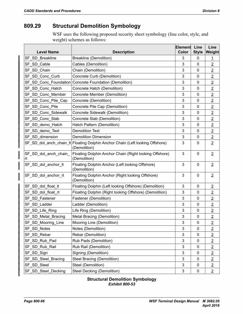
CADD Standards and Procedures Division 8
Page 800-66 WSF Terminal Design Manual M 3082.05 April 2016
809.29 Structural Demolition SymbologyWSF uses the following proposed security sheet symbology (line color, style, and weight) schemes as follows:
Level Name DescriptionElement
ColorLine Style
Line Weight
SF_SD_Breakline Breakline (Demolition) 3 0 1SF_SD_Cable Cables (Demolition) 3 0 2SF_SD_Chain Chain (Demolition) 3 0 2SF_SD_Conc_Curb Concrete Curb (Demolition) 3 0 2SF_SD_Conc_Foundation Concrete Foundation (Demolition) 3 0 2SF_SD_Conc_Hatch Concrete Hatch (Demolition) 3 0 2SF_SD_Conc_Member Concrete Member (Demolition) 3 0 2SF_SD_Conc_Pile_Cap Concrete (Demolition) 3 0 2SF_SD_Conc_Pile Concrete Pile Cap (Demolition) 3 0 2SF_SD_Conc_Sidewalk Concrete Sidewalk (Demolition) 3 0 2SF_SD_Conc_Slab Concrete Slab (Demolition) 3 0 2SF_SD_demo_Hatch Hatch Pattern (Demolition) 3 0 2SF_SD_demo_Text Demolition Text 3 0 2SF_SD_dimension Demolition Dimension 3 0 2SF_SD_dol_anch_chain_lt Floating Dolphin Anchor Chain (Left looking Offshore)
(Demolition)3 0 2
SF_SD_dol_anch_chain_rt
Floating Dolphin Anchor Chain (Right looking Offshore) (Demolition)
3 0 2
SF_SD_dol_anchor_lt Floating Dolphin Anchor (Left looking Offshore) (Demolition)
3 0 2
SF_SD_dol_anchor_rt Floating Dolphin Anchor (Right looking Offshore) (Demolition)
3 0 2
SF_SD_dol_float_lt Floating Dolphin (Left looking Offshore) (Demolition) 3 0 2SF_SD_dol_float_rt Floating Dolphin (Right looking Offshore) (Demolition) 3 0 2SF_SD_Fastener Fastener (Demolition) 3 0 2SF_SD_Ladder Ladder (Demolition) 3 0 2SF_SD_Life_Ring Life Ring (Demolition) 3 0 2SF_SD_Metal_Bracing Metal Bracing (Demolition) 3 0 2SF_SD_Mooring_Line Mooring Line (Demolition) 3 0 2SF_SD_Notes Notes (Demolition) 3 0 2SF_SD_Rebar Rebar (Demolition) 3 0 2SF_SD_Rub_Pad Rub Pads (Demolition) 3 0 2SF_SD_Rub_Rail Rub Rail (Demolition) 3 0 2SF_SD_Sign Signing (Demolition) 3 0 2SF_SD_Steel_Bracing Steel Bracing (Demolition) 3 0 2SF_SD_Steel Steel (Demolition) 3 0 2SF_SD_Steel_Decking Steel Decking (Demolition) 3 0 2
Structural Demolition SymbologyExhibit 800-53
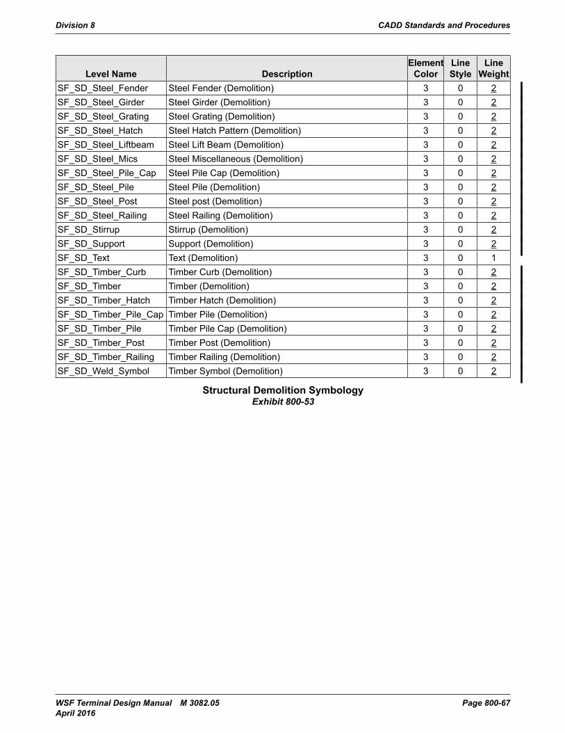
Division 8 CADD Standards and Procedures
WSF Terminal Design Manual M 3082.05 Page 800-67 April 2016
Level Name DescriptionElement
ColorLine Style
Line Weight
SF_SD_Steel_Fender Steel Fender (Demolition) 3 0 2SF_SD_Steel_Girder Steel Girder (Demolition) 3 0 2SF_SD_Steel_Grating Steel Grating (Demolition) 3 0 2SF_SD_Steel_Hatch Steel Hatch Pattern (Demolition) 3 0 2SF_SD_Steel_Liftbeam Steel Lift Beam (Demolition) 3 0 2SF_SD_Steel_Mics Steel Miscellaneous (Demolition) 3 0 2SF_SD_Steel_Pile_Cap Steel Pile Cap (Demolition) 3 0 2SF_SD_Steel_Pile Steel Pile (Demolition) 3 0 2SF_SD_Steel_Post Steel post (Demolition) 3 0 2SF_SD_Steel_Railing Steel Railing (Demolition) 3 0 2SF_SD_Stirrup Stirrup (Demolition) 3 0 2SF_SD_Support Support (Demolition) 3 0 2SF_SD_Text Text (Demolition) 3 0 1SF_SD_Timber_Curb Timber Curb (Demolition) 3 0 2SF_SD_Timber Timber (Demolition) 3 0 2SF_SD_Timber_Hatch Timber Hatch (Demolition) 3 0 2SF_SD_Timber_Pile_Cap Timber Pile (Demolition) 3 0 2SF_SD_Timber_Pile Timber Pile Cap (Demolition) 3 0 2SF_SD_Timber_Post Timber Post (Demolition) 3 0 2SF_SD_Timber_Railing Timber Railing (Demolition) 3 0 2SF_SD_Weld_Symbol Timber Symbol (Demolition) 3 0 2
Structural Demolition SymbologyExhibit 800-53
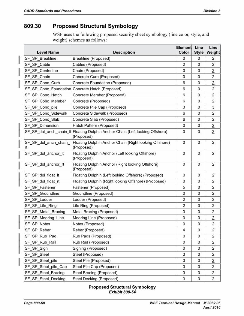
CADD Standards and Procedures Division 8
Page 800-68 WSF Terminal Design Manual M 3082.05 April 2016
809.30 Proposed Structural SymbologyWSF uses the following proposed security sheet symbology (line color, style, and weight) schemes as follows:
Level Name DescriptionElement
ColorLine Style
Line Weight
SF_SP_Breakline Breakline (Proposed) 0 0 2SF_SP_Cable Cables (Proposed) 2 0 2SF_SP_Centerline Chain (Proposed) 0 0 2SF_SP_Chain Concrete Curb (Proposed) 0 0 2SF_SP_Conc_Curb Concrete Foundation (Proposed) 6 0 2SF_SP_Conc_Foundation Concrete Hatch (Proposed) 6 0 2SF_SP_Conc_Hatch Concrete Member (Proposed) 6 0 2SF_SP_Conc_Member Concrete (Proposed) 6 0 2SF_SP_Conc_pile Concrete Pile Cap (Proposed) 3 0 3SF_SP_Conc_Sidewalk Concrete Sidewalk (Proposed) 6 0 2SF_SP_Conc_Slab Concrete Slab (Proposed) 6 0 2SF_SP_Dimension Hatch Pattern (Proposed) 0 0 2SF_SP_dol_anch_chain_lt Floating Dolphin Anchor Chain (Left looking Offshore)
(Proposed)0 0 2
SF_SP_dol_anch_chain_rt
Floating Dolphin Anchor Chain (Right looking Offshore) (Proposed)
0 0 2
SF_SP_dol_anchor_lt Floating Dolphin Anchor (Left looking Offshore) (Proposed)
0 0 2
SF_SP_dol_anchor_rt Floating Dolphin Anchor (Right looking Offshore) (Proposed)
0 0 2
SF_SP_dol_float_lt Floating Dolphin (Left looking Offshore) (Proposed) 0 0 2SF_SP_dol_float_rt Floating Dolphin (Right looking Offshore) (Proposed) 0 0 2SF_SP_Fastener Fastener (Proposed) 5 0 2SF_SP_Groundline Groundline (Proposed) 0 0 2SF_SP_Ladder Ladder (Proposed) 2 0 2SF_SP_Life_Ring Life Ring (Proposed) 2 0 2SF_SP_Metal_Bracing Metal Bracing (Proposed) 3 0 2SF_SP_Mooring_Line Mooring Line (Proposed) 0 0 2SF_SP_Notes Notes (Proposed) 0 0 2SF_SP_Rebar Rebar (Proposed) 4 0 2SF_SP_Rub_Pad Rub Pads (Proposed) 0 0 2SF_SP_Rub_Rail Rub Rail (Proposed) 0 0 2SF_SP_Sign Signing (Proposed) 0 0 2SF_SP_Steel Steel (Proposed) 3 0 2SF_SP_Steel_pile Steel Pile (Proposed) 3 0 2SF_SP_Steel_pile_Cap Steel Pile Cap (Proposed) 3 0 2SF_SP_Steel_Bracing Steel Bracing (Proposed) 3 0 2SF_SP_Steel_Decking Steel Decking (Proposed) 3 0 2
Proposed Structural SymbologyExhibit 800-54
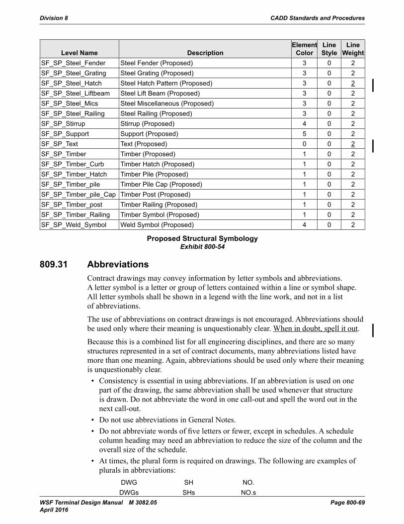
Division 8 CADD Standards and Procedures
WSF Terminal Design Manual M 3082.05 Page 800-69 April 2016
Level Name DescriptionElement
ColorLine Style
Line Weight
SF_SP_Steel_Fender Steel Fender (Proposed) 3 0 2SF_SP_Steel_Grating Steel Grating (Proposed) 3 0 2SF_SP_Steel_Hatch Steel Hatch Pattern (Proposed) 3 0 2SF_SP_Steel_Liftbeam Steel Lift Beam (Proposed) 3 0 2SF_SP_Steel_Mics Steel Miscellaneous (Proposed) 3 0 2SF_SP_Steel_Railing Steel Railing (Proposed) 3 0 2SF_SP_Stirrup Stirrup (Proposed) 4 0 2SF_SP_Support Support (Proposed) 5 0 2SF_SP_Text Text (Proposed) 0 0 2SF_SP_Timber Timber (Proposed) 1 0 2SF_SP_Timber_Curb Timber Hatch (Proposed) 1 0 2SF_SP_Timber_Hatch Timber Pile (Proposed) 1 0 2SF_SP_Timber_pile Timber Pile Cap (Proposed) 1 0 2SF_SP_Timber_pile_Cap Timber Post (Proposed) 1 0 2SF_SP_Timber_post Timber Railing (Proposed) 1 0 2SF_SP_Timber_Railing Timber Symbol (Proposed) 1 0 2SF_SP_Weld_Symbol Weld Symbol (Proposed) 4 0 2
Proposed Structural SymbologyExhibit 800-54
809.31 AbbreviationsContract drawings may convey information by letter symbols and abbreviations. A letter symbol is a letter or group of letters contained within a line or symbol shape. All letter symbols shall be shown in a legend with the line work, and not in a list of abbreviations.
The use of abbreviations on contract drawings is not encouraged. Abbreviations should be used only where their meaning is unquestionably clear. When in doubt, spell it out.
Because this is a combined list for all engineering disciplines, and there are so many structures represented in a set of contract documents, many abbreviations listed have more than one meaning. Again, abbreviations should be used only where their meaning is unquestionably clear. • Consistency is essential in using abbreviations. If an abbreviation is used on one
part of the drawing, the same abbreviation shall be used whenever that structure is drawn. Do not abbreviate the word in one call-out and spell the word out in the next call-out.
• Do not use abbreviations in General Notes.• Donotabbreviatewordsoffivelettersorfewer,exceptinschedules.Aschedule
column heading may need an abbreviation to reduce the size of the column and the overall size of the schedule.
• At times, the plural form is required on drawings. The following are examples of plurals in abbreviations:
DWG SH NO.DWGs SHs NO.s
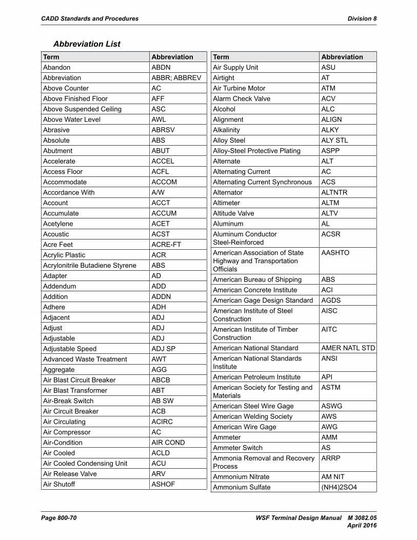
CADD Standards and Procedures Division 8
Page 800-70 WSF Terminal Design Manual M 3082.05 April 2016
Abbreviation ListTerm AbbreviationAbandon ABDNAbbreviation ABBR; ABBREVAbove Counter ACAbove Finished Floor AFFAbove Suspended Ceiling ASCAbove Water Level AWLAbrasive ABRSVAbsolute ABSAbutment ABUTAccelerate ACCELAccess Floor ACFLAccommodate ACCOMAccordance With A/WAccount ACCTAccumulate ACCUMAcetylene ACETAcoustic ACSTAcre Feet ACRE-FTAcrylic Plastic ACRAcrylonitrile Butadiene Styrene ABSAdapter ADAddendum ADDAddition ADDNAdhere ADHAdjacent ADJAdjust ADJAdjustable ADJAdjustable Speed ADJ SPAdvanced Waste Treatment AWTAggregate AGGAir Blast Circuit Breaker ABCBAir Blast Transformer ABTAir-Break Switch AB SWAir Circuit Breaker ACBAir Circulating ACIRCAir Compressor ACAir-Condition AIR CONDAir Cooled ACLDAir Cooled Condensing Unit ACUAir Release Valve ARVAir Shutoff ASHOF
Term AbbreviationAir Supply Unit ASUAirtight ATAir Turbine Motor ATMAlarm Check Valve ACVAlcohol ALCAlignment ALIGNAlkalinity ALKYAlloy Steel ALY STLAlloy-Steel Protective Plating ASPPAlternate ALTAlternating Current ACAlternating Current Synchronous ACSAlternator ALTNTRAltimeter ALTMAltitude Valve ALTVAluminum ALAluminum Conductor Steel-Reinforced
ACSR
American Association of State Highway and Transportation Officials
AASHTO
American Bureau of Shipping ABSAmerican Concrete Institute ACIAmerican Gage Design Standard AGDSAmerican Institute of Steel Construction
AISC
American Institute of Timber Construction
AITC
American National Standard AMER NATL STDAmerican National Standards Institute
ANSI
American Petroleum Institute APIAmerican Society for Testing and Materials
ASTM
American Steel Wire Gage ASWGAmerican Welding Society AWSAmerican Wire Gage AWGAmmeter AMMAmmeter Switch ASAmmonia Removal and Recovery Process
ARRP
Ammonium Nitrate AM NITAmmonium Sulfate (NH4)2SO4
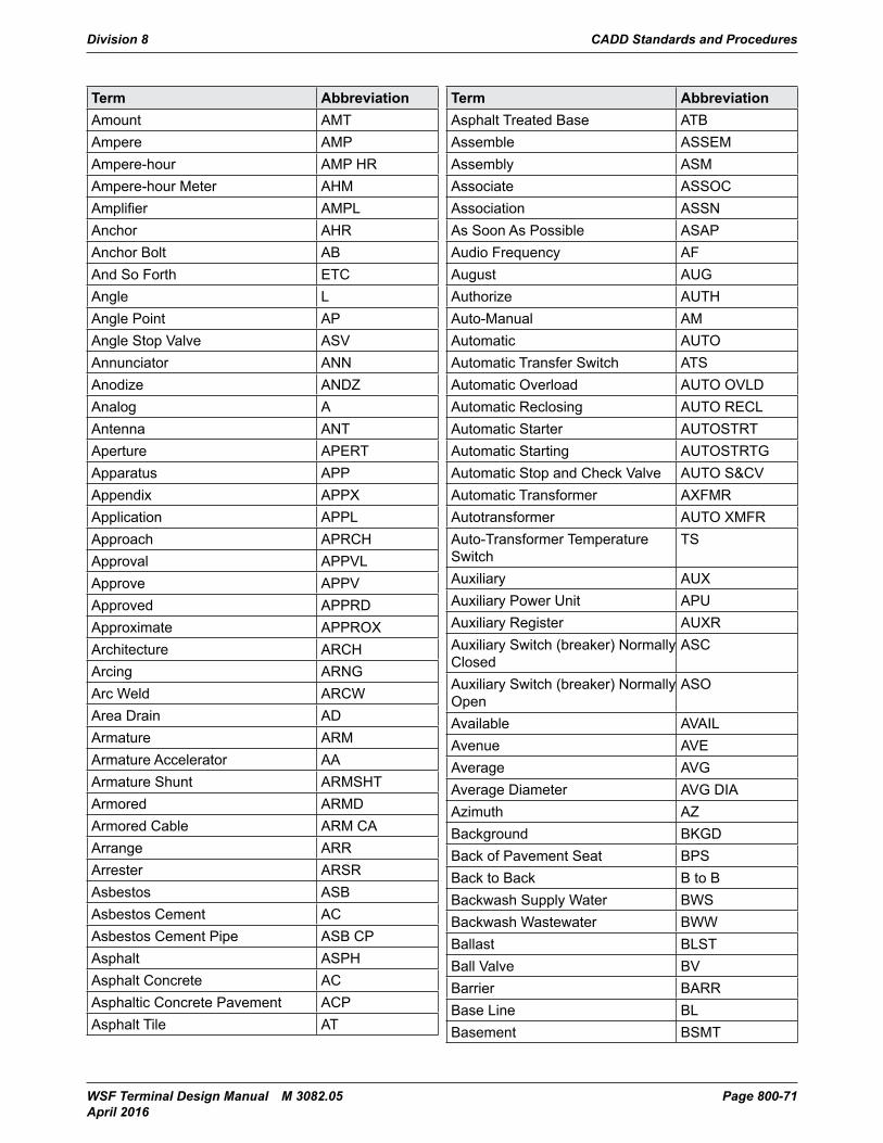
Division 8 CADD Standards and Procedures
WSF Terminal Design Manual M 3082.05 Page 800-71 April 2016
Term AbbreviationAmount AMTAmpere AMPAmpere-hour AMP HRAmpere-hour Meter AHMAmplifier AMPLAnchor AHRAnchor Bolt ABAnd So Forth ETCAngle LAngle Point APAngle Stop Valve ASVAnnunciator ANNAnodize ANDZAnalog AAntenna ANTAperture APERTApparatus APPAppendix APPXApplication APPLApproach APRCHApproval APPVLApprove APPVApproved APPRDApproximate APPROXArchitecture ARCHArcing ARNGArc Weld ARCWArea Drain ADArmature ARMArmature Accelerator AAArmature Shunt ARMSHTArmored ARMDArmored Cable ARM CAArrange ARRArrester ARSRAsbestos ASBAsbestos Cement ACAsbestos Cement Pipe ASB CPAsphalt ASPHAsphalt Concrete ACAsphaltic Concrete Pavement ACPAsphalt Tile AT
Term AbbreviationAsphalt Treated Base ATBAssemble ASSEMAssembly ASMAssociate ASSOCAssociation ASSNAs Soon As Possible ASAPAudio Frequency AFAugust AUGAuthorize AUTHAuto-Manual AMAutomatic AUTOAutomatic Transfer Switch ATSAutomatic Overload AUTO OVLDAutomatic Reclosing AUTO RECLAutomatic Starter AUTOSTRTAutomatic Starting AUTOSTRTGAutomatic Stop and Check Valve AUTO S&CVAutomatic Transformer AXFMRAutotransformer AUTO XMFRAuto-Transformer Temperature Switch
TS
Auxiliary AUXAuxiliary Power Unit APUAuxiliary Register AUXRAuxiliary Switch (breaker) Normally Closed
ASC
Auxiliary Switch (breaker) Normally Open
ASO
Available AVAILAvenue AVEAverage AVGAverage Diameter AVG DIAAzimuth AZBackground BKGDBack of Pavement Seat BPSBack to Back B to BBackwash Supply Water BWSBackwash Wastewater BWWBallast BLSTBall Valve BVBarrier BARRBase Line BLBasement BSMT
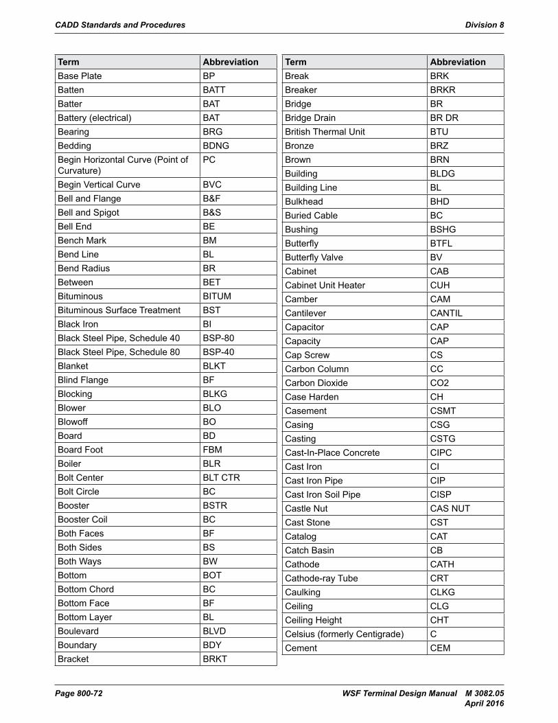
CADD Standards and Procedures Division 8
Page 800-72 WSF Terminal Design Manual M 3082.05 April 2016
Term AbbreviationBase Plate BPBatten BATTBatter BATBattery (electrical) BATBearing BRGBedding BDNGBegin Horizontal Curve (Point of Curvature)
PC
Begin Vertical Curve BVCBell and Flange B&FBell and Spigot B&SBell End BEBench Mark BMBend Line BLBend Radius BRBetween BETBituminous BITUMBituminous Surface Treatment BSTBlack Iron BIBlack Steel Pipe, Schedule 40 BSP-80Black Steel Pipe, Schedule 80 BSP-40Blanket BLKTBlind Flange BFBlocking BLKGBlower BLOBlowoff BOBoard BDBoard Foot FBMBoiler BLRBolt Center BLT CTRBolt Circle BCBooster BSTRBooster Coil BCBoth Faces BFBoth Sides BSBoth Ways BWBottom BOTBottom Chord BCBottom Face BFBottom Layer BLBoulevard BLVDBoundary BDYBracket BRKT
Term AbbreviationBreak BRKBreaker BRKRBridge BRBridge Drain BR DRBritish Thermal Unit BTUBronze BRZBrown BRNBuilding BLDGBuilding Line BLBulkhead BHDBuried Cable BCBushing BSHGButterfly BTFLButterfly Valve BVCabinet CABCabinet Unit Heater CUHCamber CAMCantilever CANTILCapacitor CAPCapacity CAPCap Screw CSCarbon Column CCCarbon Dioxide CO2Case Harden CHCasement CSMTCasing CSGCasting CSTGCast-In-Place Concrete CIPCCast Iron CICast Iron Pipe CIPCast Iron Soil Pipe CISPCastle Nut CAS NUTCast Stone CSTCatalog CATCatch Basin CBCathode CATHCathode-ray Tube CRTCaulking CLKGCeiling CLGCeiling Height CHTCelsius (formerly Centigrade) CCement CEM
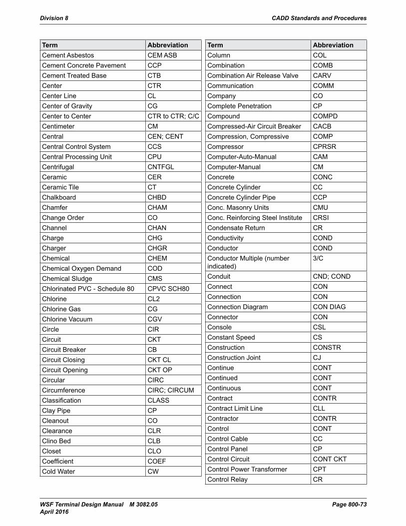
Division 8 CADD Standards and Procedures
WSF Terminal Design Manual M 3082.05 Page 800-73 April 2016
Term AbbreviationCement Asbestos CEM ASBCement Concrete Pavement CCPCement Treated Base CTBCenter CTRCenter Line CLCenter of Gravity CGCenter to Center CTR to CTR; C/CCentimeter CMCentral CEN; CENTCentral Control System CCSCentral Processing Unit CPUCentrifugal CNTFGLCeramic CERCeramic Tile CTChalkboard CHBDChamfer CHAMChange Order COChannel CHANCharge CHGCharger CHGRChemical CHEMChemical Oxygen Demand CODChemical Sludge CMSChlorinated PVC - Schedule 80 CPVC SCH80Chlorine CL2Chlorine Gas CGChlorine Vacuum CGVCircle CIRCircuit CKTCircuit Breaker CBCircuit Closing CKT CLCircuit Opening CKT OPCircular CIRCCircumference CIRC; CIRCUMClassification CLASSClay Pipe CPCleanout COClearance CLRClino Bed CLBCloset CLOCoefficient COEFCold Water CW
Term AbbreviationColumn COLCombination COMBCombination Air Release Valve CARVCommunication COMMCompany COComplete Penetration CPCompound COMPDCompressed-Air Circuit Breaker CACBCompression, Compressive COMPCompressor CPRSRComputer-Auto-Manual CAMComputer-Manual CMConcrete CONCConcrete Cylinder CCConcrete Cylinder Pipe CCPConc. Masonry Units CMUConc. Reinforcing Steel Institute CRSICondensate Return CRConductivity CONDConductor COND Conductor Multiple (number indicated)
3/C
Conduit CND; CONDConnect CONConnection CONConnection Diagram CON DIAGConnector CONConsole CSLConstant Speed CSConstruction CONSTRConstruction Joint CJContinue CONTContinued CONTContinuous CONTContract CONTRContract Limit Line CLLContractor CONTRControl CONTControl Cable CCControl Panel CPControl Circuit CONT CKTControl Power Transformer CPTControl Relay CR
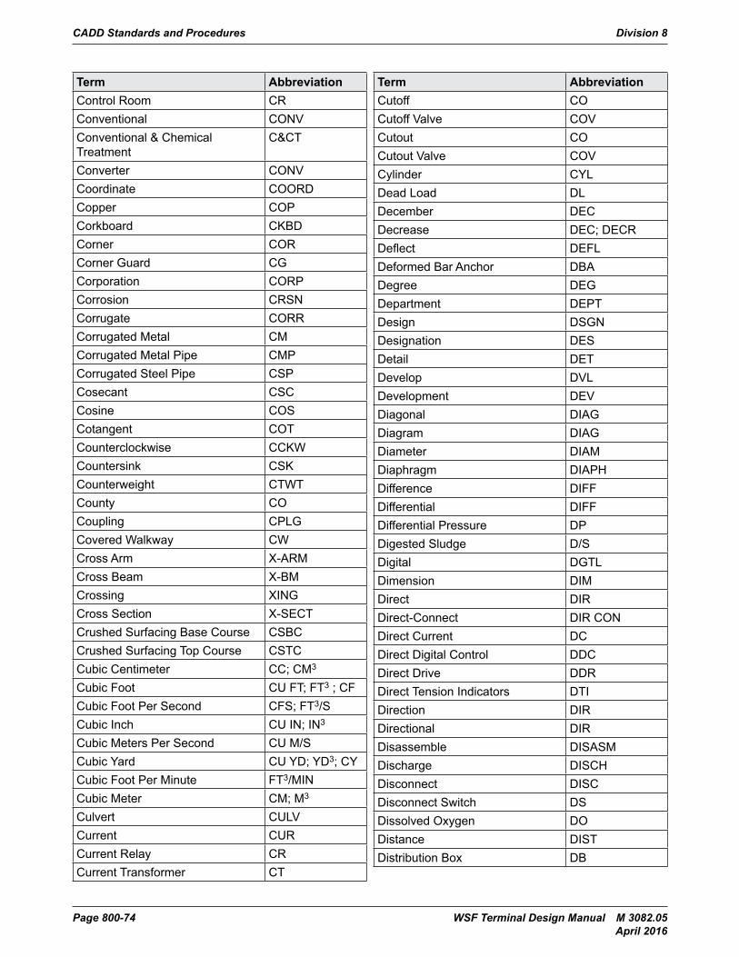
CADD Standards and Procedures Division 8
Page 800-74 WSF Terminal Design Manual M 3082.05 April 2016
Term AbbreviationControl Room CRConventional CONVConventional & Chemical Treatment
C&CT
Converter CONVCoordinate COORDCopper COPCorkboard CKBDCorner CORCorner Guard CGCorporation CORPCorrosion CRSNCorrugate CORRCorrugated Metal CMCorrugated Metal Pipe CMPCorrugated Steel Pipe CSPCosecant CSCCosine COSCotangent COTCounterclockwise CCKWCountersink CSKCounterweight CTWTCounty COCoupling CPLGCovered Walkway CWCross Arm X-ARMCross Beam X-BMCrossing XINGCross Section X-SECTCrushed Surfacing Base Course CSBCCrushed Surfacing Top Course CSTCCubic Centimeter CC; CM3
Cubic Foot CU FT; FT3 ; CFCubic Foot Per Second CFS; FT3/SCubic Inch CU IN; IN3
Cubic Meters Per Second CU M/SCubic Yard CU YD; YD3; CYCubic Foot Per Minute FT3/MINCubic Meter CM; M3
Culvert CULVCurrent CURCurrent Relay CRCurrent Transformer CT
Term AbbreviationCutoff COCutoff Valve COVCutout COCutout Valve COVCylinder CYLDead Load DLDecember DECDecrease DEC; DECRDeflect DEFLDeformed Bar Anchor DBADegree DEGDepartment DEPTDesign DSGNDesignation DESDetail DETDevelop DVLDevelopment DEVDiagonal DIAGDiagram DIAGDiameter DIAMDiaphragm DIAPHDifference DIFFDifferential DIFFDifferential Pressure DPDigested Sludge D/SDigital DGTLDimension DIMDirect DIRDirect-Connect DIR CONDirect Current DCDirect Digital Control DDCDirect Drive DDRDirect Tension Indicators DTIDirection DIRDirectional DIRDisassemble DISASMDischarge DISCHDisconnect DISCDisconnect Switch DSDissolved Oxygen DODistance DISTDistribution Box DB
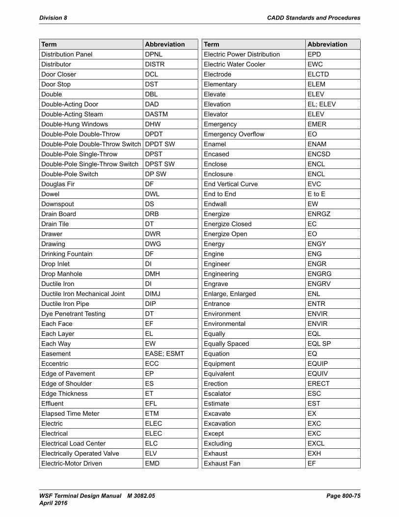
Division 8 CADD Standards and Procedures
WSF Terminal Design Manual M 3082.05 Page 800-75 April 2016
Term AbbreviationDistribution Panel DPNLDistributor DISTRDoor Closer DCLDoor Stop DSTDouble DBLDouble-Acting Door DADDouble-Acting Steam DASTMDouble-Hung Windows DHWDouble-Pole Double-Throw DPDTDouble-Pole Double-Throw Switch DPDT SWDouble-Pole Single-Throw DPSTDouble-Pole Single-Throw Switch DPST SWDouble-Pole Switch DP SWDouglas Fir DFDowel DWLDownspout DSDrain Board DRBDrain Tile DTDrawer DWRDrawing DWGDrinking Fountain DFDrop Inlet DIDrop Manhole DMHDuctile Iron DIDuctile Iron Mechanical Joint DIMJDuctile Iron Pipe DIPDye Penetrant Testing DTEach Face EFEach Layer ELEach Way EWEasement EASE; ESMTEccentric ECCEdge of Pavement EPEdge of Shoulder ESEdge Thickness ETEffluent EFLElapsed Time Meter ETMElectric ELECElectrical ELECElectrical Load Center ELCElectrically Operated Valve ELVElectric-Motor Driven EMD
Term AbbreviationElectric Power Distribution EPDElectric Water Cooler EWCElectrode ELCTDElementary ELEMElevate ELEVElevation EL; ELEVElevator ELEVEmergency EMEREmergency Overflow EOEnamel ENAMEncased ENCSDEnclose ENCLEnclosure ENCLEnd Vertical Curve EVCEnd to End E to EEndwall EWEnergize ENRGZEnergize Closed ECEnergize Open EOEnergy ENGYEngine ENGEngineer ENGREngineering ENGRGEngrave ENGRVEnlarge, Enlarged ENLEntrance ENTREnvironment ENVIREnvironmental ENVIREqually EQLEqually Spaced EQL SPEquation EQEquipment EQUIPEquivalent EQUIVErection ERECTEscalator ESCEstimate ESTExcavate EXExcavation EXCExcept EXCExcluding EXCLExhaust EXHExhaust Fan EF
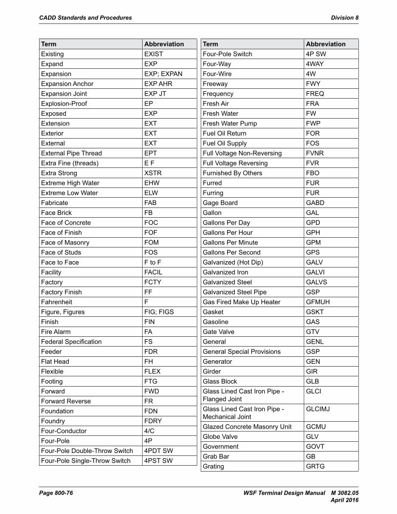
CADD Standards and Procedures Division 8
Page 800-76 WSF Terminal Design Manual M 3082.05 April 2016
Term AbbreviationExisting EXISTExpand EXPExpansion EXP; EXPANExpansion Anchor EXP AHRExpansion Joint EXP JTExplosion-Proof EPExposed EXPExtension EXTExterior EXTExternal EXTExternal Pipe Thread EPTExtra Fine (threads) E FExtra Strong XSTRExtreme High Water EHWExtreme Low Water ELWFabricate FABFace Brick FBFace of Concrete FOCFace of Finish FOFFace of Masonry FOMFace of Studs FOSFace to Face F to FFacility FACILFactory FCTYFactory Finish FFFahrenheit FFigure, Figures FIG; FIGSFinish FINFire Alarm FAFederal Specification FSFeeder FDRFlat Head FHFlexible FLEXFooting FTGForward FWDForward Reverse FRFoundation FDNFoundry FDRYFour-Conductor 4/CFour-Pole 4PFour-Pole Double-Throw Switch 4PDT SWFour-Pole Single-Throw Switch 4PST SW
Term AbbreviationFour-Pole Switch 4P SWFour-Way 4WAYFour-Wire 4WFreeway FWYFrequency FREQFresh Air FRAFresh Water FWFresh Water Pump FWPFuel Oil Return FORFuel Oil Supply FOSFull Voltage Non-Reversing FVNRFull Voltage Reversing FVRFurnished By Others FBOFurred FURFurring FURGage Board GABDGallon GALGallons Per Day GPDGallons Per Hour GPHGallons Per Minute GPMGallons Per Second GPSGalvanized (Hot Dip) GALVGalvanized Iron GALVIGalvanized Steel GALVSGalvanized Steel Pipe GSPGas Fired Make Up Heater GFMUHGasket GSKTGasoline GASGate Valve GTVGeneral GENLGeneral Special Provisions GSPGenerator GENGirder GIRGlass Block GLBGlass Lined Cast Iron Pipe - Flanged Joint
GLCI
Glass Lined Cast Iron Pipe - Mechanical Joint
GLCIMJ
Glazed Concrete Masonry Unit GCMUGlobe Valve GLVGovernment GOVTGrab Bar GBGrating GRTG
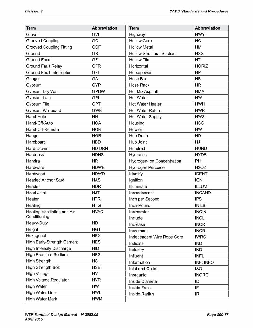
Division 8 CADD Standards and Procedures
WSF Terminal Design Manual M 3082.05 Page 800-77 April 2016
Term AbbreviationGravel GVLGrooved Coupling GCGrooved Coupling Fitting GCFGround GRGround Face GFGround Fault Relay GFRGround Fault Interrupter GFIGuage GAGypsum GYPGypsum Dry Wall GPDWGypsum Lath GPLGypsum Tile GPTGypsum Wallboard GWBHand-Hole HHHand-Off-Auto HOAHand-Off-Remote HORHanger HGRHardboard HBDHard-Drawn HD DRNHardness HDNSHandrail HRHardware HDWEHardwood HDWDHeaded Anchor Stud HASHeader HDRHead Joint HJTHeater HTRHeating HTGHeating Ventilating and Air Conditioning
HVAC
Heavy-Duty HDHeight HGTHexagonal HEXHigh Early-Strength Cement HESHigh Intensity Discharge HIDHigh Pressure Sodium HPSHigh Strength HSHigh Strength Bolt HSBHigh Voltage HVHigh Voltage Regulator HVRHigh Water HWHigh Water Line HWLHigh Water Mark HWM
Term AbbreviationHighway HWYHollow Core HCHollow Metal HMHollow Structural Section HSSHollow Tile HTHorizontal HORIZHorsepower HPHose Bib HBHose Rack HRHot Mix Asphalt HMAHot Water HWHot Water Heater HWHHot Water Return HWRHot Water Supply HWSHousing HSGHowler HWHub Drain HDHub Joint HJHundred HUNDHydraulic HYDRHydrogen-Ion Concentration PHHydrogen Peroxide H2O2Identify IDENTIgnition IGNIlluminate ILLUMIncandescent INCANDInch per Second IPSInch-Pound IN LBIncinerator INCINInclude INCLIncrease INCRIncrement INCRIndependent Wire Rope Core IWRCIndicate INDIndustry INDInfluent INFLInformation INF; INFOInlet and Outlet I&OInorganic INORGInside Diameter IDInside Face IFInside Radius IR
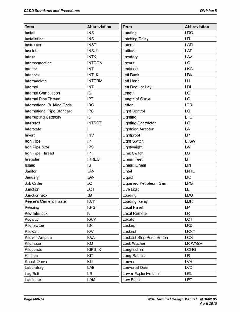
CADD Standards and Procedures Division 8
Page 800-78 WSF Terminal Design Manual M 3082.05 April 2016
Term AbbreviationInstall INSInstallation INSInstrument INSTInsulate INSULIntake INTKInterconnection INTCONInterior INTInterlock INTLKIntermediate INTERMInternal INTLInternal Combustion ICInternal Pipe Thread IPTInternational Building Code IBCInternational Pipe Standard IPSInterrupting Capacity ICIntersect INTSCTInterstate IInvert INVIron Pipe IPIron Pipe Size IPSIron Pipe Thread IPTIrregular IRREGIsland ISJanitor JANJanuary JANJob Order JOJunction JCTJunction Box JBKeene’s Cement Plaster KCPKeeping KPGKey Interlock KKeyway KWYKilonewton KNKilowatt KWKilovolt Ampere KVAKilometer KMKilopunds KIPS; KKitchen KITKnock Down KDLaboratory LABLag Bolt LBLaminate LAM
Term AbbreviationLanding LDGLatching Relay LRLateral LATLLatitude LATLavatory LAVLayout LOLeakage LKGLeft Bank LBKLeft Hand LHLeft Regular Lay LRLLength LGLength of Curve LCLetter LTRLight Control LCLighting LTGLighting Contractor LCLightning Arrester LALightproof LPLight Switch LTSWLightweight LWLimit Switch LSLinear Feet LFLinear, Lineal LINLintel LNTLLiquid LIQLiquefied Petroleum Gas LPGLive Load LLLoading LDGLoading Relay LDRLocal Panel LPLocal Remote LRLocate LCTLocked LKDLocknut LKNTLockout Stop Push Button LOSLock Washer LK WASHLongitudinal LONGLong Radius LRLouver LVRLouvered Door LVDLower Explosive Limit LELLow Point LPT
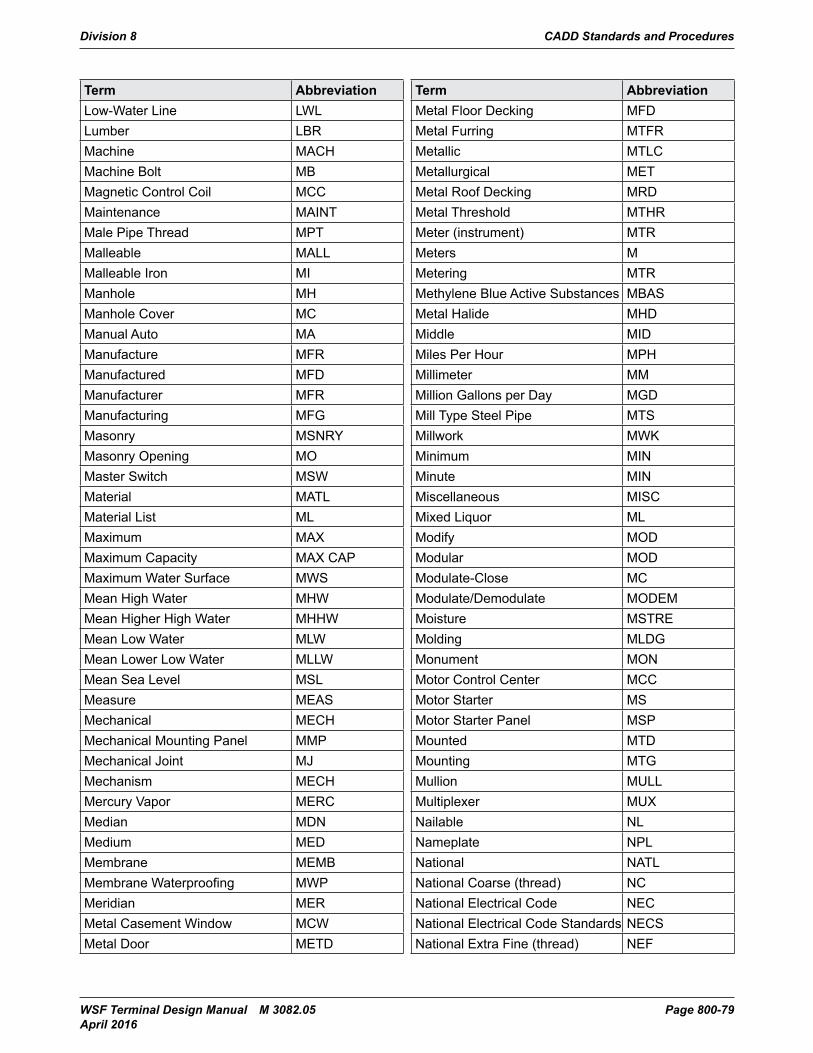
Division 8 CADD Standards and Procedures
WSF Terminal Design Manual M 3082.05 Page 800-79 April 2016
Term AbbreviationLow-Water Line LWLLumber LBRMachine MACHMachine Bolt MBMagnetic Control Coil MCCMaintenance MAINTMale Pipe Thread MPTMalleable MALLMalleable Iron MIManhole MHManhole Cover MCManual Auto MAManufacture MFRManufactured MFDManufacturer MFRManufacturing MFGMasonry MSNRYMasonry Opening MOMaster Switch MSWMaterial MATLMaterial List MLMaximum MAXMaximum Capacity MAX CAPMaximum Water Surface MWSMean High Water MHWMean Higher High Water MHHWMean Low Water MLWMean Lower Low Water MLLWMean Sea Level MSLMeasure MEASMechanical MECHMechanical Mounting Panel MMPMechanical Joint MJMechanism MECHMercury Vapor MERCMedian MDNMedium MEDMembrane MEMBMembrane Waterproofing MWPMeridian MERMetal Casement Window MCWMetal Door METD
Term AbbreviationMetal Floor Decking MFDMetal Furring MTFRMetallic MTLCMetallurgical METMetal Roof Decking MRDMetal Threshold MTHRMeter (instrument) MTRMeters MMetering MTRMethylene Blue Active Substances MBASMetal Halide MHDMiddle MIDMiles Per Hour MPHMillimeter MMMillion Gallons per Day MGDMill Type Steel Pipe MTSMillwork MWKMinimum MINMinute MINMiscellaneous MISCMixed Liquor MLModify MODModular MODModulate-Close MCModulate/Demodulate MODEMMoisture MSTREMolding MLDGMonument MONMotor Control Center MCCMotor Starter MSMotor Starter Panel MSPMounted MTDMounting MTGMullion MULLMultiplexer MUXNailable NLNameplate NPLNational NATLNational Coarse (thread) NCNational Electrical Code NECNational Electrical Code Standards NECSNational Extra Fine (thread) NEF
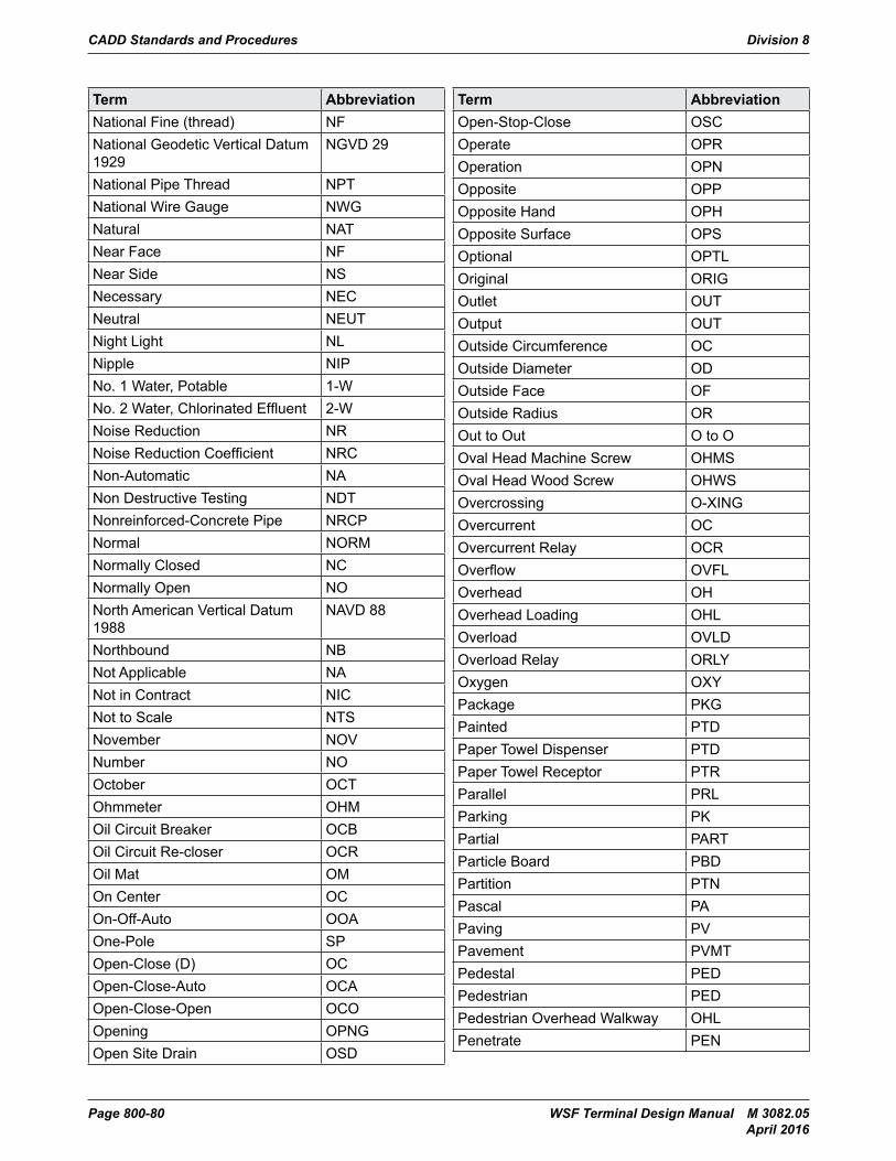
CADD Standards and Procedures Division 8
Page 800-80 WSF Terminal Design Manual M 3082.05 April 2016
Term AbbreviationNational Fine (thread) NFNational Geodetic Vertical Datum 1929
NGVD 29
National Pipe Thread NPTNational Wire Gauge NWGNatural NATNear Face NFNear Side NSNecessary NECNeutral NEUTNight Light NLNipple NIPNo. 1 Water, Potable 1-WNo. 2 Water, Chlorinated Effluent 2-WNoise Reduction NRNoise Reduction Coefficient NRCNon-Automatic NANon Destructive Testing NDTNonreinforced-Concrete Pipe NRCPNormal NORMNormally Closed NCNormally Open NONorth American Vertical Datum 1988
NAVD 88
Northbound NBNot Applicable NANot in Contract NICNot to Scale NTSNovember NOVNumber NOOctober OCTOhmmeter OHMOil Circuit Breaker OCBOil Circuit Re-closer OCROil Mat OMOn Center OCOn-Off-Auto OOAOne-Pole SPOpen-Close (D) OCOpen-Close-Auto OCAOpen-Close-Open OCOOpening OPNGOpen Site Drain OSD
Term AbbreviationOpen-Stop-Close OSCOperate OPROperation OPNOpposite OPPOpposite Hand OPHOpposite Surface OPSOptional OPTLOriginal ORIGOutlet OUTOutput OUTOutside Circumference OCOutside Diameter ODOutside Face OFOutside Radius OROut to Out O to OOval Head Machine Screw OHMSOval Head Wood Screw OHWSOvercrossing O-XINGOvercurrent OCOvercurrent Relay OCROverflow OVFLOverhead OHOverhead Loading OHLOverload OVLDOverload Relay ORLYOxygen OXYPackage PKGPainted PTDPaper Towel Dispenser PTDPaper Towel Receptor PTRParallel PRLParking PKPartial PARTParticle Board PBDPartition PTNPascal PAPaving PVPavement PVMTPedestal PEDPedestrian PEDPedestrian Overhead Walkway OHLPenetrate PEN
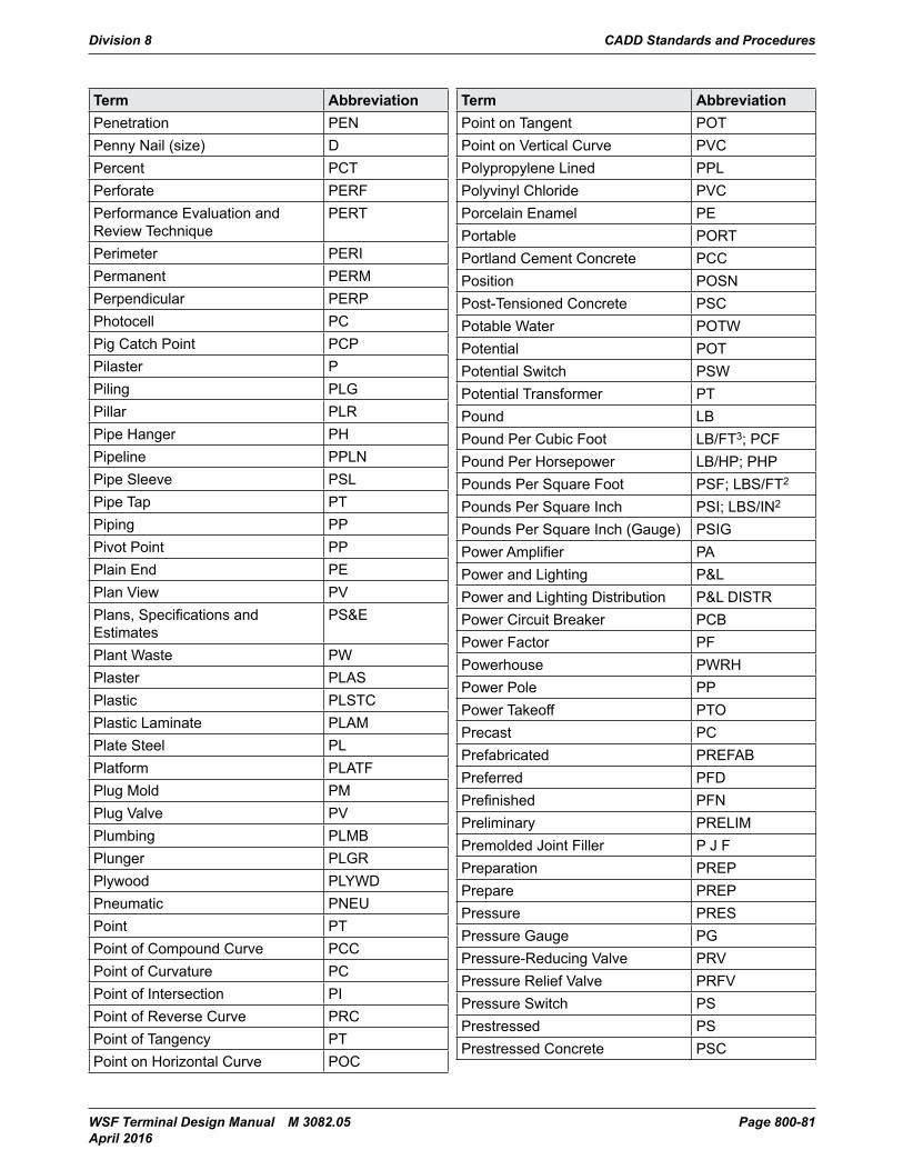
Division 8 CADD Standards and Procedures
WSF Terminal Design Manual M 3082.05 Page 800-81 April 2016
Term AbbreviationPenetration PENPenny Nail (size) DPercent PCTPerforate PERFPerformance Evaluation and Review Technique
PERT
Perimeter PERIPermanent PERMPerpendicular PERPPhotocell PCPig Catch Point PCPPilaster PPiling PLGPillar PLRPipe Hanger PHPipeline PPLNPipe Sleeve PSLPipe Tap PTPiping PPPivot Point PPPlain End PEPlan View PVPlans, Specifications and Estimates
PS&E
Plant Waste PWPlaster PLASPlastic PLSTCPlastic Laminate PLAMPlate Steel PLPlatform PLATFPlug Mold PMPlug Valve PVPlumbing PLMBPlunger PLGRPlywood PLYWDPneumatic PNEUPoint PTPoint of Compound Curve PCCPoint of Curvature PCPoint of Intersection PIPoint of Reverse Curve PRCPoint of Tangency PTPoint on Horizontal Curve POC
Term AbbreviationPoint on Tangent POTPoint on Vertical Curve PVCPolypropylene Lined PPLPolyvinyl Chloride PVCPorcelain Enamel PEPortable PORTPortland Cement Concrete PCCPosition POSNPost-Tensioned Concrete PSCPotable Water POTWPotential POTPotential Switch PSWPotential Transformer PTPound LBPound Per Cubic Foot LB/FT3; PCFPound Per Horsepower LB/HP; PHPPounds Per Square Foot PSF; LBS/FT2
Pounds Per Square Inch PSI; LBS/IN2
Pounds Per Square Inch (Gauge) PSIGPower Amplifier PAPower and Lighting P&LPower and Lighting Distribution P&L DISTRPower Circuit Breaker PCBPower Factor PFPowerhouse PWRHPower Pole PPPower Takeoff PTOPrecast PCPrefabricated PREFABPreferred PFDPrefinished PFNPreliminary PRELIMPremolded Joint Filler P J FPreparation PREPPrepare PREPPressure PRESPressure Gauge PGPressure-Reducing Valve PRVPressure Relief Valve PRFVPressure Switch PSPrestressed PSPrestressed Concrete PSC
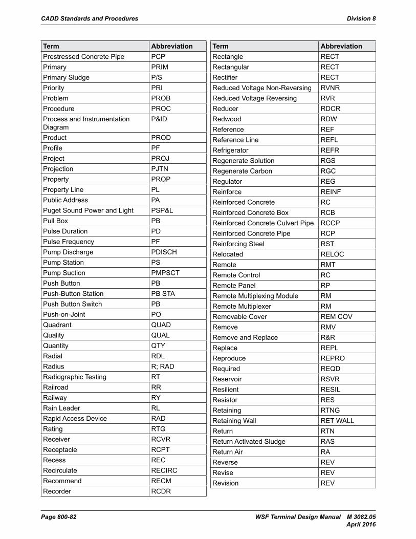
CADD Standards and Procedures Division 8
Page 800-82 WSF Terminal Design Manual M 3082.05 April 2016
Term AbbreviationPrestressed Concrete Pipe PCPPrimary PRIMPrimary Sludge P/SPriority PRIProblem PROBProcedure PROCProcess and Instrumentation Diagram
P&ID
Product PRODProfile PFProject PROJProjection PJTNProperty PROPProperty Line PLPublic Address PAPuget Sound Power and Light PSP&LPull Box PBPulse Duration PDPulse Frequency PFPump Discharge PDISCHPump Station PSPump Suction PMPSCTPush Button PBPush-Button Station PB STAPush Button Switch PBPush-on-Joint POQuadrant QUADQuality QUALQuantity QTYRadial RDLRadius R; RADRadiographic Testing RTRailroad RRRailway RYRain Leader RLRapid Access Device RADRating RTGReceiver RCVRReceptacle RCPTRecess RECRecirculate RECIRCRecommend RECMRecorder RCDR
Term AbbreviationRectangle RECTRectangular RECTRectifier RECTReduced Voltage Non-Reversing RVNRReduced Voltage Reversing RVRReducer RDCRRedwood RDWReference REFReference Line REFLRefrigerator REFRRegenerate Solution RGSRegenerate Carbon RGCRegulator REGReinforce REINFReinforced Concrete RCReinforced Concrete Box RCBReinforced Concrete Culvert Pipe RCCPReinforced Concrete Pipe RCPReinforcing Steel RSTRelocated RELOCRemote RMTRemote Control RCRemote Panel RPRemote Multiplexing Module RMRemote Multiplexer RMRemovable Cover REM COVRemove RMVRemove and Replace R&RReplace REPLReproduce REPRORequired REQDReservoir RSVRResilient RESILResistor RESRetaining RTNGRetaining Wall RET WALLReturn RTNReturn Activated Sludge RASReturn Air RAReverse REVRevise REVRevision REV
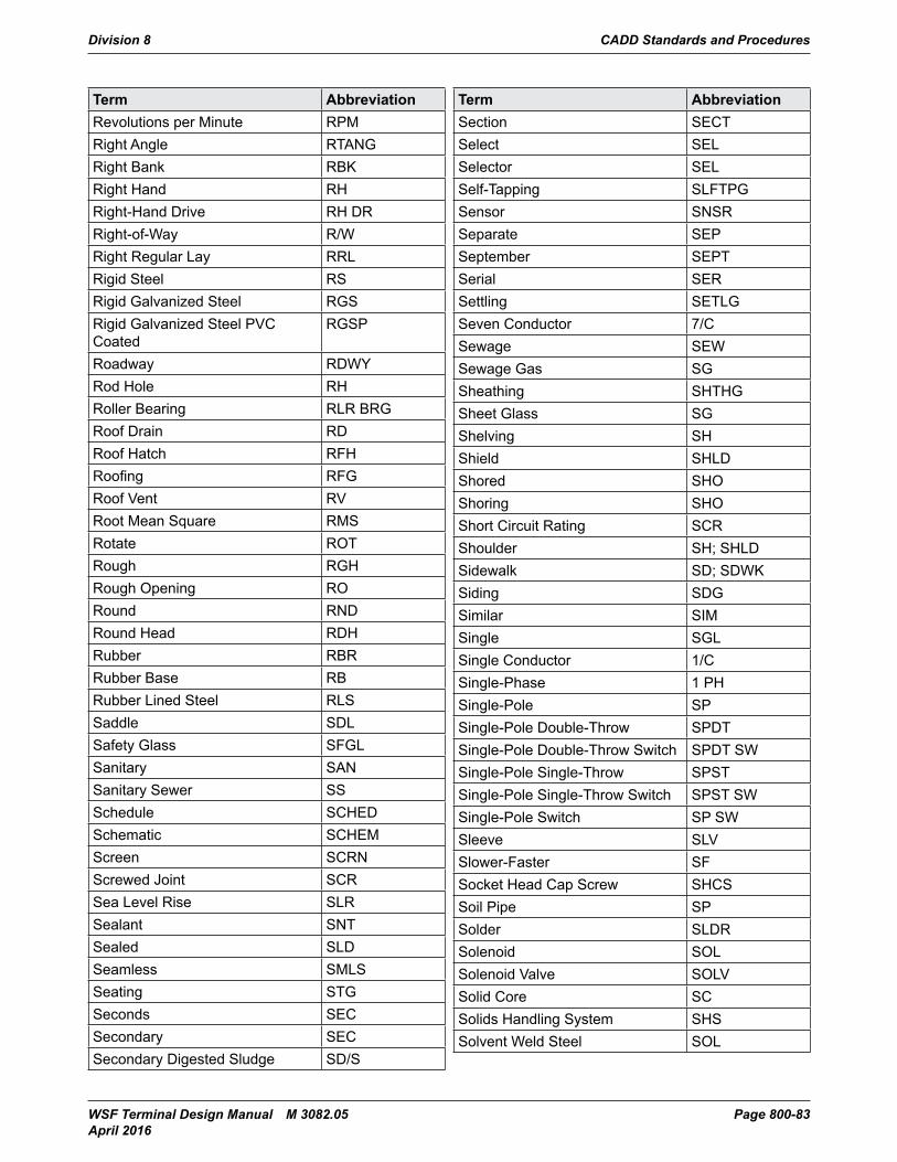
Division 8 CADD Standards and Procedures
WSF Terminal Design Manual M 3082.05 Page 800-83 April 2016
Term AbbreviationRevolutions per Minute RPMRight Angle RTANGRight Bank RBKRight Hand RHRight-Hand Drive RH DRRight-of-Way R/WRight Regular Lay RRLRigid Steel RSRigid Galvanized Steel RGSRigid Galvanized Steel PVC Coated
RGSP
Roadway RDWYRod Hole RHRoller Bearing RLR BRGRoof Drain RDRoof Hatch RFHRoofing RFGRoof Vent RVRoot Mean Square RMSRotate ROTRough RGHRough Opening RORound RNDRound Head RDHRubber RBRRubber Base RBRubber Lined Steel RLSSaddle SDLSafety Glass SFGLSanitary SANSanitary Sewer SSSchedule SCHEDSchematic SCHEMScreen SCRNScrewed Joint SCRSea Level Rise SLRSealant SNTSealed SLDSeamless SMLSSeating STGSeconds SECSecondary SECSecondary Digested Sludge SD/S
Term AbbreviationSection SECTSelect SELSelector SELSelf-Tapping SLFTPGSensor SNSRSeparate SEPSeptember SEPTSerial SERSettling SETLGSeven Conductor 7/CSewage SEWSewage Gas SGSheathing SHTHGSheet Glass SGShelving SHShield SHLDShored SHOShoring SHOShort Circuit Rating SCRShoulder SH; SHLDSidewalk SD; SDWKSiding SDGSimilar SIMSingle SGLSingle Conductor 1/CSingle-Phase 1 PHSingle-Pole SPSingle-Pole Double-Throw SPDTSingle-Pole Double-Throw Switch SPDT SWSingle-Pole Single-Throw SPSTSingle-Pole Single-Throw Switch SPST SWSingle-Pole Switch SP SWSleeve SLVSlower-Faster SFSocket Head Cap Screw SHCSSoil Pipe SPSolder SLDRSolenoid SOLSolenoid Valve SOLVSolid Core SCSolids Handling System SHSSolvent Weld Steel SOL
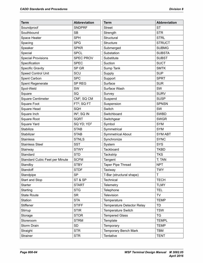
CADD Standards and Procedures Division 8
Page 800-84 WSF Terminal Design Manual M 3082.05 April 2016
Term AbbreviationSoundproof SNDPRFSouthbound SBSpace Heater SPHSpacing SPGSpeaker SPKRSpecial SPCLSpecial Provisions SPEC PROVSpecification SPECSpecific Gravity SP GRSpeed Control Unit SCUSpent Carbon SPCSpent Regenerate SP REGSpot-Weld SWSquare SQSquare Centimeter CM2; SQ CMSquare Foot FT2; SQ FTSquare Head SQHSquare Inch IN2; SQ INSquare Root SQRTSquare Yard SQ YD; YD2
Stabilize STABStabilizer STABStainless STNLSStainless Steel SSTStairway STWYStandard STDStandard Cubic Feet per Minute SCFMStandby STBYStandoff STDFStandpipe SPStart and Stop ST & SPStarter STARTStarting STGState Route SRStation STAStiffener STIFFStirrup STIRStorage STORStoreroom STRMStorm Drain SDStraight STRStrainer STR
Term AbbreviationStreet STStrength STRStructural STRLStructure STRUCTSubmerged SUBMGSubstation SUBSTASubstitute SUBSTSuction SUCTSump Tank SMTKSupply SUPSupport SPRTSurface SUR Surface Wash SWSurvey SURVSuspend SUSPSuspension SPNSNSwitch SWSwitchboard SWBDSwitchgear SWGRSymbol SYMSymmetrical SYMSymmetrical About SYM ABTSynchronize SYNCSystem SYSTackboard TKBDTackstrip TKSTangent T; TANTaper Pipe Thread NPTTaxiway TWYT-Bar (structural shape) TTechnical TECHTelemetry TLMYTelephone TELTelevision TVTemperature TEMPTemperature Detector Relay TDTemperature Switch TSWTempered Glass TGTemplate TEMPLTemporary TEMPTemporary Bench Mark TBMTentative TENT
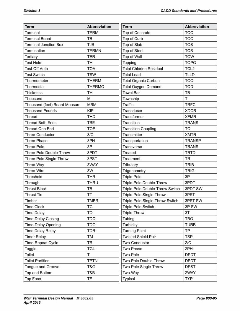
Division 8 CADD Standards and Procedures
WSF Terminal Design Manual M 3082.05 Page 800-85 April 2016
Term AbbreviationTerminal TERMTerminal Board TBTerminal Junction Box TJBTermination TERMNTertiary TERTest Hole THTest-Off-Auto TOATest Switch TSWThermometer THERMThermostat THERMOThickness TH Thousand MThousand (feet) Board Measure MBMThousand Pounds KIPThread THDThread Both Ends TBEThread One End TOEThree-Conductor 3/CThree-Phase 3PHThree-Pole 3PThree-Pole Double-Throw 3PDTThree-Pole Single-Throw 3PSTThree-Way 3WAYThree-Wire 3WThreshold THRThrough THRUThrust Block TBThrust Tie TTTimber TMBRTime Clock TCTime Delay TDTime-Delay Closing TDCTime-Delay Opening TDOTime Delay Relay TDRTimer Relay TMTime-Repeat Cycle TRToggle TGLToilet TToilet Partition TPTNTongue and Groove T>op and Bottom T&BTop Face TF
Term AbbreviationTop of Concrete TOCTop of Curb TOCTop of Slab TOSTop of Steel TOSTop of Wall TOWTopping TOPGTotal Chlorine Residual TCL2Total Load TLLDTotal Organic Carbon TOCTotal Oxygen Demand TODTowel Bar TBTownship TTraffic TRFCTransducer XDCRTransformer XFMRTransition TRANSTransition Coupling TCTransmitter XMTRTransportation TRANSPTransverse TRANSTreated TRTDTreatment TRTributary TRIBTrigonometry TRIGTriple-Pole 3PTriple-Pole Double-Throw 3PDTTriple-Pole Double-Throw Switch 3PDT SWTriple-Pole Single-Throw 3PSTTriple-Pole Single-Throw Switch 3PST SWTriple-Pole Switch 3P SWTriple-Throw 3TTubing TBGTurbidity TURBTurning Point TPTwisted Shield Pair TSPTwo-Conductor 2/CTwo-Phase 2PHTwo-Pole DPDTTwo-Pole Double-Throw DPDTTwo-Pole Single-Throw DPSTTwo-Way 2WAYTypical TYP
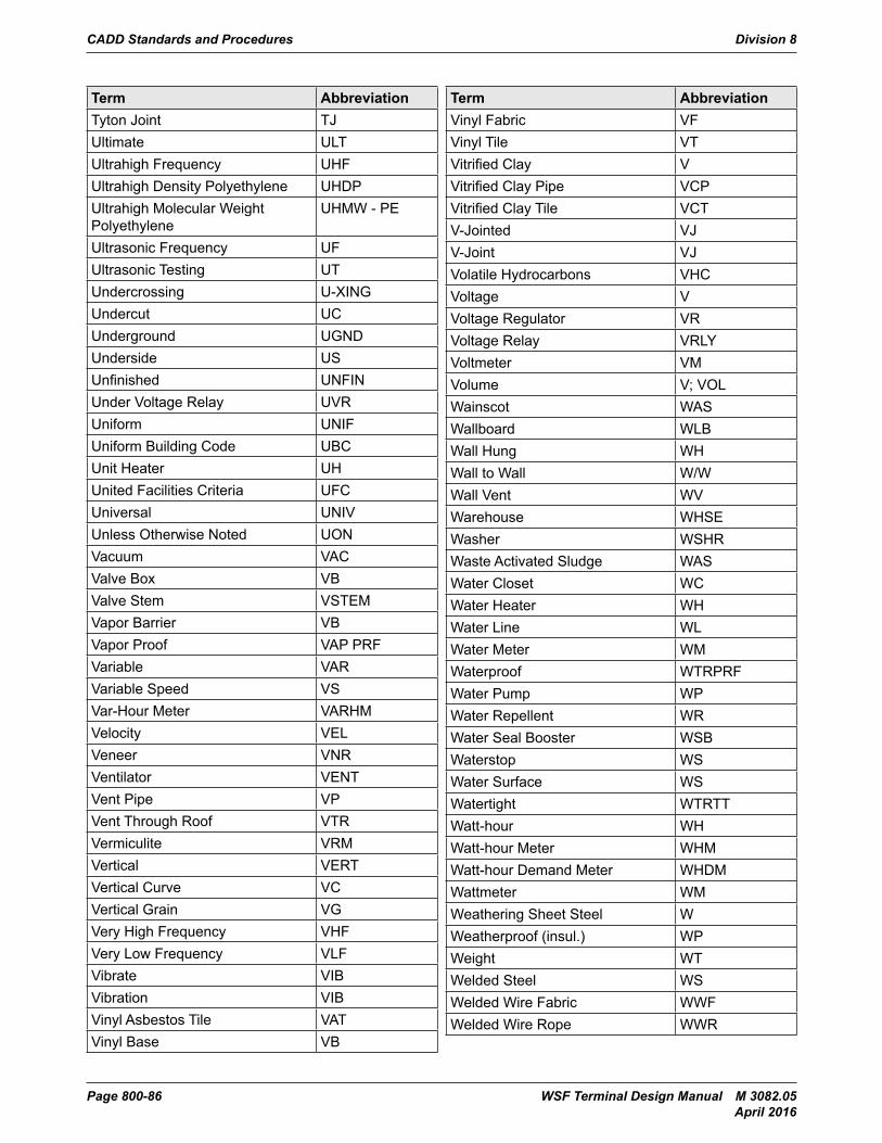
CADD Standards and Procedures Division 8
Page 800-86 WSF Terminal Design Manual M 3082.05 April 2016
Term AbbreviationTyton Joint TJUltimate ULTUltrahigh Frequency UHFUltrahigh Density Polyethylene UHDPUltrahigh Molecular Weight Polyethylene
UHMW - PE
Ultrasonic Frequency UFUltrasonic Testing UTUndercrossing U-XINGUndercut UCUnderground UGNDUnderside USUnfinished UNFINUnder Voltage Relay UVRUniform UNIFUniform Building Code UBCUnit Heater UHUnited Facilities Criteria UFCUniversal UNIVUnless Otherwise Noted UONVacuum VACValve Box VBValve Stem VSTEMVapor Barrier VBVapor Proof VAP PRFVariable VARVariable Speed VSVar-Hour Meter VARHMVelocity VELVeneer VNRVentilator VENTVent Pipe VPVent Through Roof VTRVermiculite VRMVertical VERTVertical Curve VCVertical Grain VGVery High Frequency VHFVery Low Frequency VLFVibrate VIBVibration VIBVinyl Asbestos Tile VATVinyl Base VB
Term AbbreviationVinyl Fabric VFVinyl Tile VTVitrified Clay VVitrified Clay Pipe VCPVitrified Clay Tile VCTV-Jointed VJV-Joint VJVolatile Hydrocarbons VHCVoltage VVoltage Regulator VRVoltage Relay VRLYVoltmeter VMVolume V; VOLWainscot WASWallboard WLBWall Hung WHWall to Wall W/WWall Vent WVWarehouse WHSEWasher WSHRWaste Activated Sludge WASWater Closet WCWater Heater WHWater Line WLWater Meter WMWaterproof WTRPRFWater Pump WPWater Repellent WRWater Seal Booster WSBWaterstop WSWater Surface WSWatertight WTRTTWatt-hour WHWatt-hour Meter WHMWatt-hour Demand Meter WHDMWattmeter WMWeathering Sheet Steel WWeatherproof (insul.) WPWeight WTWelded Steel WSWelded Wire Fabric WWFWelded Wire Rope WWR
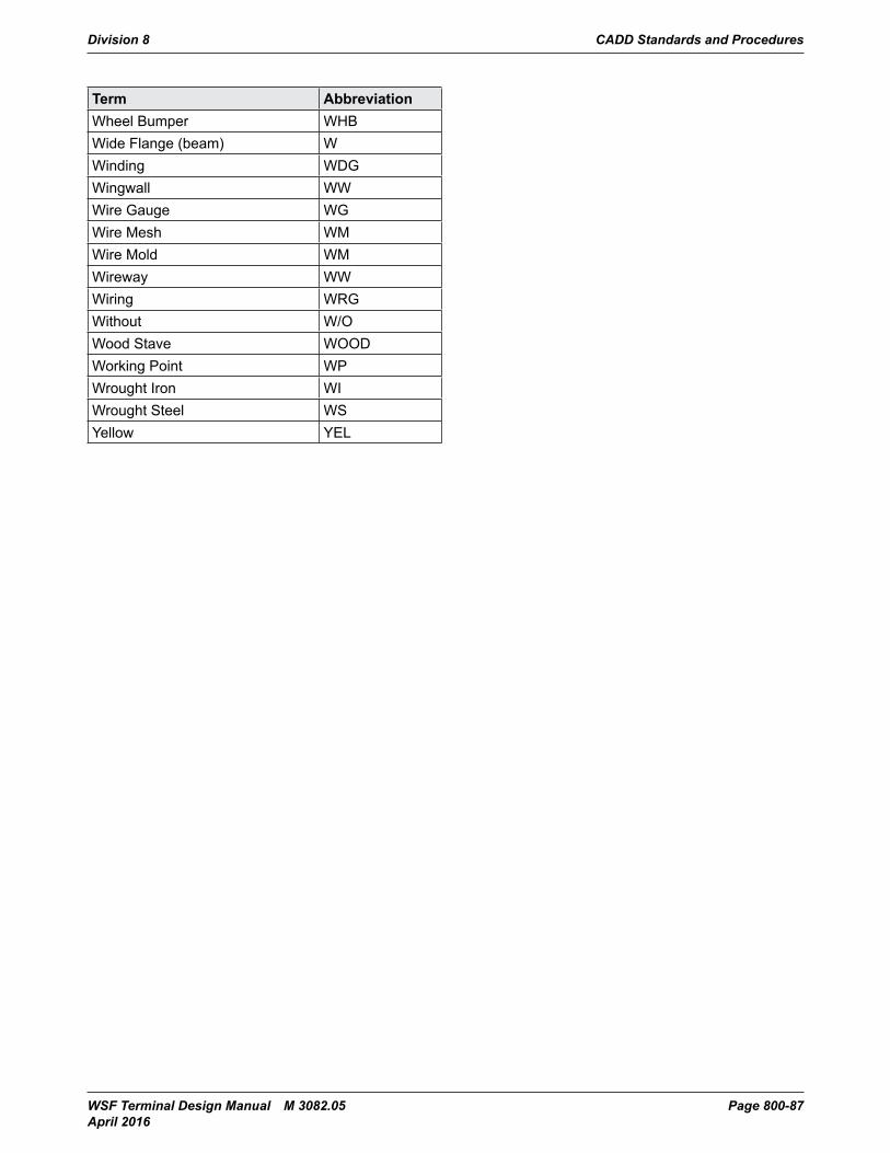
Division 8 CADD Standards and Procedures
WSF Terminal Design Manual M 3082.05 Page 800-87 April 2016
Term AbbreviationWheel Bumper WHBWide Flange (beam) WWinding WDGWingwall WWWire Gauge WGWire Mesh WMWire Mold WMWireway WWWiring WRGWithout W/OWood Stave WOODWorking Point WPWrought Iron WIWrought Steel WSYellow YEL
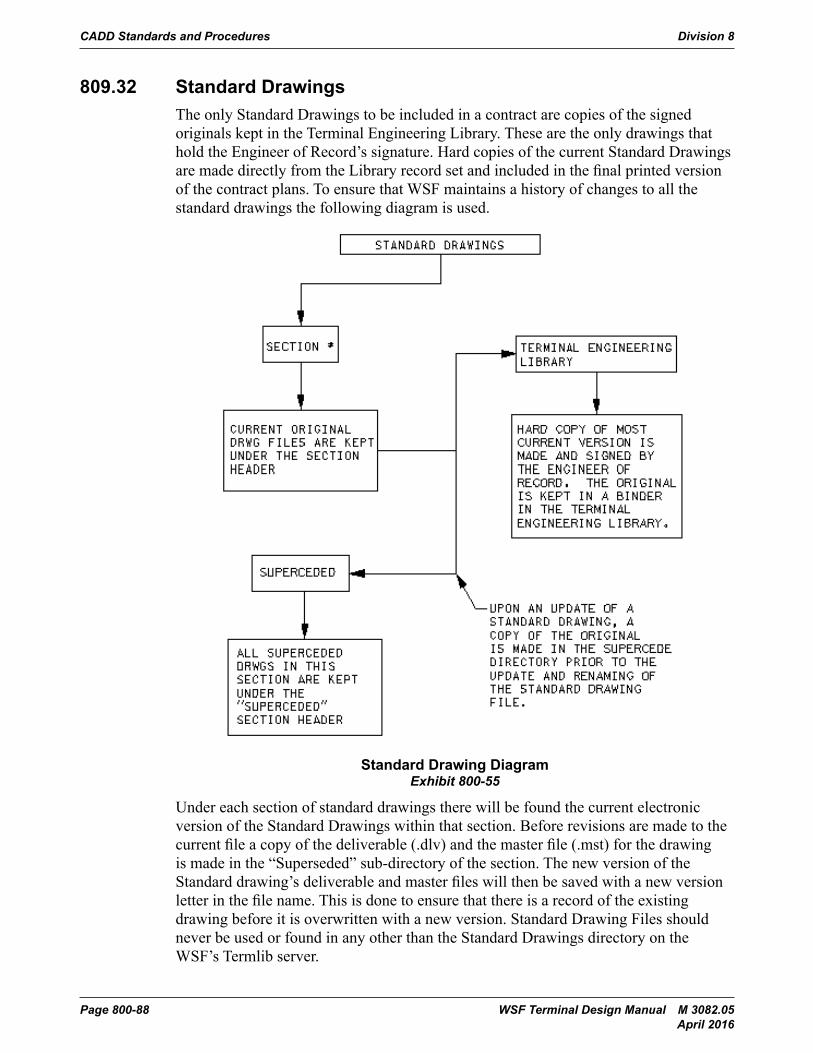
CADD Standards and Procedures Division 8
Page 800-88 WSF Terminal Design Manual M 3082.05 April 2016
809.32 Standard DrawingsThe only Standard Drawings to be included in a contract are copies of the signed originals kept in the Terminal Engineering Library. These are the only drawings that hold the Engineer of Record’s signature. Hard copies of the current Standard Drawings are made directly from the Library record set and included in the final printed version of the contract plans. To ensure that WSF maintains a history of changes to all the standard drawings the following diagram is used.
Terminal Design Manual M 3082 Page 800-73Division 800
809.32 Standard DrawingsThe only Standard Drawings to be included in a contract are copies of the signed originals kept in the Terminal Engineering Library. These are the only drawings that hold the Engineer of Record’s signature. Hard copies of the current Standard Drawings are made directly from the Library record set and included in the final printed version of the contract plans. To ensure that WSF maintains a history of changes to all the standard drawings the following diagram is used.
Exhibit 800-52: Standard Drawing Diagram
Under each section of standard drawings there will be found the current electronic version of the Standard Drawings within that section. Before revisions are made to the current file a copy of the deliverable (.dlv) and the master file (.mst) for the drawing is made in the “Superseded” sub-directory of the section. The new version of the Standard drawing’s deliverable and master files will then be saved with a new version letter in the file name.
Standard Drawing DiagramExhibit 800-55
Under each section of standard drawings there will be found the current electronic version of the Standard Drawings within that section. Before revisions are made to the current file a copy of the deliverable (.dlv) and the master file (.mst) for the drawing is made in the “Superseded” sub-directory of the section. The new version of the Standard drawing’s deliverable and master files will then be saved with a new version letter in the file name. This is done to ensure that there is a record of the existing drawing before it is overwritten with a new version. Standard Drawing Files should never be used or found in any other than the Standard Drawings directory on the WSF’s Termlib server.
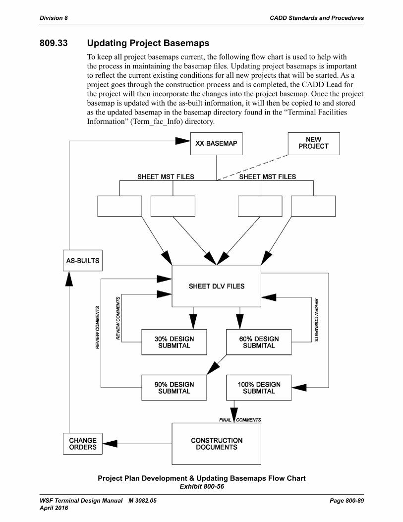
Division 8 CADD Standards and Procedures
WSF Terminal Design Manual M 3082.05 Page 800-89 April 2016
809.33 Updating Project BasemapsTo keep all project basemaps current, the following flow chart is used to help with the process in maintaining the basemap files. Updating project basemaps is important to reflect the current existing conditions for all new projects that will be started. As a project goes through the construction process and is completed, the CADD Lead for the project will then incorporate the changes into the project basemap. Once the project basemap is updated with the as-built information, it will then be copied to and stored as the updated basemap in the basemap directory found in the “Terminal Facilities Information” (Term_fac_Info) directory.
CADD Standards and Procedures Division 800
Terminal Design Manual M 3082 Page 800-75March 2014
Exhibit 800-53: Project Plan Development & Updating Basemaps Flow ChartProject Plan Development & Updating Basemaps Flow ChartExhibit 800-56
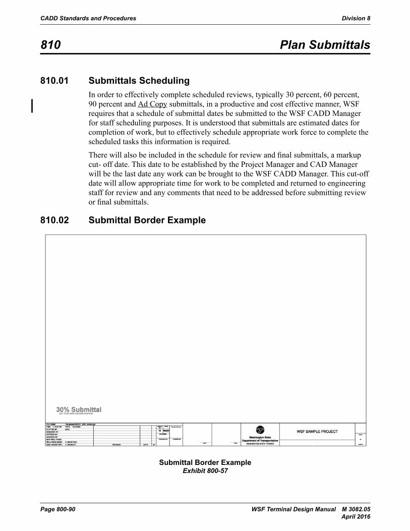
CADD Standards and Procedures Division 8
Page 800-90 WSF Terminal Design Manual M 3082.05 April 2016
810 Plan Submittals
810.01 Submittals SchedulingIn order to effectively complete scheduled reviews, typically 30 percent, 60 percent, 90 percent and Ad Copy submittals, in a productive and cost effective manner, WSF requires that a schedule of submittal dates be submitted to the WSF CADD Manager for staff scheduling purposes. It is understood that submittals are estimated dates for completion of work, but to effectively schedule appropriate work force to complete the scheduled tasks this information is required.
There will also be included in the schedule for review and final submittals, a markup cut- off date. This date to be established by the Project Manager and CAD Manager will be the last date any work can be brought to the WSF CADD Manager. This cut-off date will allow appropriate time for work to be completed and returned to engineering staff for review and any comments that need to be addressed before submitting review or final submittals.
810.02 Submittal Border Example
CADD Standards and Procedures Division 800
Page 800-76 Terminal Design Manual M 3082March 2014
810 Plan Submittals
810.01 Submittals SchedulingIn order to effectively complete scheduled reviews, typically 30%, 60%, 90% and Ad Copy submittals, in a productive and cost effective manner, WSF requires that a schedule of submittal dates be submitted to the WSF CADD Manager for staff scheduling purposes. It is understood that submittals are estimated dates for completion of work, but to effectively schedule appropriate work force to complete the scheduled tasks this information is required.
There will also be included in the schedule for review and final submittals, a markup cut- off date. This date to be established by the Project Manager and CAD Manager will be the last date any work can be brought to the WSF CADD Manager. This cut-off date will allow appropriate time for work to be completed and returned to engineering staff for review and any comments that need to be addressed before submitting review or final submittals.
810.02 Submittal Border Example
Submittal Border Example
Exhibit 800-57
Division 8 CADD Standards and Procedures
WSF Terminal Design Manual M 3082.05 Page 800-91 April 2016
810.03 Review SubmittalsOnce the plan set has been prepared for submittal an experienced CADD operator must perform a drafting plan review. Once the plan set has been amended to incorporate changes from this review the plan set will be ready for distribution for review by WSF staff and other associated parties.
Once the plot files have successfully plotted, they are ready for PS&E archive submittal. The plan files will be copied to the folder titled with the next submittal stage. The files left in the just completed submittal folder will be compressed and left as a record to previous project submittals.
810.04 Final SubmittalsSubmittal of the final plan set will follow the same process as that for review submittals with the exception that; once the plans have been sealed and approved for transmittal to Olympia for Advertisement, the CADD Manager will archive the entirety of the project CADD directory to the Terminal Design archive on the U: drive.
Upon completion of the design portion of the project the design team leader shall generate a memorandum to the WSF CADD Manager. The memo shall request that a CD be created containing the contents of the project directory. A copy of this memo shall be given to the WSF Marine Project Engineer and a copy shall be placed in the project files.
The CD shall contain the entire final PS&E submittal. A copy of this CD will be archived with the Project archives kept at the home offices of Washington State Ferries Terminal Engineering.
810.05 Design File ArchivingOnce the final submittal is completed and has been signed by all pertinent engineers, the files will be transferred to the U:\ drive (archive drive). After the files have been transferred it is considered a completed project and write access is restricted. A CD of the project along with any Standard drawings will be compiled and stored as a backup copy to that on the server.
CADD Standards and Procedures Division 8
Page 800-92 WSF Terminal Design Manual M 3082.05 April 2016
810.06 As-Built DrawingsIt is standard business practice for WSDOT to obtain As-built drawings at the close of the construction project. These drawings are to be continuously updated with the changes, substitutions, and as-built information that occur during the course of the project. Some As-built information will require changes be made to the WSF basemap.
CADD copies of the As-built drawings will be kept with the archived project CADD files in a folder labeled “AS-BUILTS”
G:\Term_Fac_Info\”Terminal”\Facility_Plans\”Terminal”_basemap.mst
Examples of work that require changes to the basemap are:• Placement of new utility lines• Construction of new on site structures• Replacement of existing structures with more current technology• Relocation of existing elements
(See Section 809.33 for information on updating the project basemap.)
Division 8 CADD Standards and Procedures
WSF Terminal Design Manual M 3082.05 Page 800-93 April 2016
811 Environmental Permit Standards
811.01 Permit Drawing ChecklistThere are two different types of drawings required for permit applications: Joint Aquatic Resource Permits Application (JARPA) drawings and Substantial Shoreline Development drawings. JARPA drawings are submitted to the U.S. Army Corps of Engineers (Corps), the Washington Department of Fish and Wildlife (WDFW), the Washington Department of Ecology (Ecology), National Marine Fisheries Service (NMFS), and the U.S. Fish and Wildlife Service (USFWS). These agencies have different areas of jurisdiction and different regulatory mandates. Since the JARPA is the same for these agencies, each of their specific areas of jurisdiction must be shown on the drawings.
The Shoreline drawings are sent to local jurisdictions. Many local jurisdictions have their own requirements in addition to those required for the JARPA application. Differences include: scale, drawing size, and location of neighboring properties. The JARPA drawing works for some local jurisdictions, and can provide the basis for Shoreline drawings. An Environmental Permitting staff person will supply any additional information required by the City or County you are working in.
In addition to the Guidance for Completion of Drawings found in this section, the following information will assist in the preparation of permit drawings:• Permit drawings, dimensions, scale bars, and contour lines will be in English
measurement notation.• Show the distance from MHHW to the point of Construction closest to shore and
furthest from shore. If the area is too large to show sufficient detail in the plan view show the area or distance from MHHW to the work area on one sheet. Then include an additional sheet with a closer detail of the work.
• Show the depths of the work (i.e., for a dolphin, indicate the approximate depth of that dolphin) in contour intervals of 2 feet.
• Include Datum indicators.• Include the Section, Township, and Range numbers for the terminal location. • A vicinity map shall be placed in an upper corner of the plan view.• All information shall be presented in a standard border.• All drawings shall be to scale.
CADD Standards and Procedures Division 8
Page 800-94 WSF Terminal Design Manual M 3082.05 April 2016
811.02 Format of DrawingsThe following is a list of requirements for permit drawings.
(a) Guidance for Completion of DrawingsRequired Drawings Three types of illustrations are needed to properly depict the proposed activity: Vicinity Map, Plan View, and Cross-Sectional View. Coast Guard Bridge Permit drawings must also include clearance and elevation views. Drawings to scale should be prepared using clear printing, black ink, and the fewest number of sheets possible. Include the scale. The importance of clear accurate drawings cannot be overstated. At a minimum, drawings must contain the following information; other information may be required depending on project type. If you have questions regarding completing the drawings, call the appropriate agency.
1. Vicinity Map
A copy of a county or city road map, or a U.S. Geological Survey topographic map may be used. Include:
a. North arrow.
b. Name of water body (and river mile if appropriate).
c. Location of the proposed activity (indicate with a circle, arrow, X, or similar symbol).
d. Provide latitude and longitude of the site to the nearest second.
e. Provide directions to the site – this is usually done using roads.
2. Plan View
This drawing illustrates the proposed project area as if you were looking down at the site from overhead.
a. North arrow.
b. Name of water body and direction of water flow.
c. Location of existing shoreline. For Shoreline permits, show 200’ landward and waterward of the shoreline. For tidal and non-tidal waters show the following:
i. Tidal Waters: Show the Mean Higher High and Mean Lower Low Water Marks, and/or wetland boundaries. Indicate elevation above datum.
ii. Non-tidal waters: Show the Ordinary High Water Mark or Line, Meander Line, and/or wetland boundary.
d. Dimensions of the activity or structure and impervious surfaces, distance from property lines, and the distance it extends into the water body beyond the Mean Higher High, and Mean Low Water Mark or Line, and/or wetland boundaries, as appropriate.
Division 8 CADD Standards and Procedures
WSF Terminal Design Manual M 3082.05 Page 800-95 April 2016
e. For Corps permits, indicate the distance to Federal projects and/or navigation channels (if applicable). To ascertain, call the Corps Regulatory Branch Office at (206) 764-3495.
f. Show existing structures on subject and adjoining properties.
g. Indicate adjoining property ownership.
h. If fill material is to be placed, identify the type of material, amount of material (cubic yards), and area to be filled (acres).
i. If project involves dredging, identify the type of material, amount of material (cubic yards), area to be dredged, method of dredging, and location of disposal site. Dredging in areas shallower than -10 feet needs to be clearly identified on drawings.
j. Identify any part of the activity that has been completed.
k. Indicate types and location of aquatic, wetland, riparian and upland vegetation.
l. The Following are not applicable on most projects—consult with the permitting department:
i. Erosion control measures, stabilization of disturbed areas, etc.
ii. Utilities, including water, sanitary sewer, power and stormwater conveyance systems (e.g., bioswales).
iii. Indicate stormwater discharge points.
iv. Proposed landscaping where applicable (for complex landscape plans, please attach a separate drawing).
v. Where applicable, plans for development of areas on or off site as mitigation for impacts associated with the proposal.
vi. On all variance applications the plans shall clearly indicate where development could occur without approval of a variance, the physical features and circumstances on the property that provide a basis for the request, and the location of adjacent structures and uses.
3. Cross-Sectional View
This drawing illustrates the proposed activity as if it were cut from the side and/or front. Include:
a. Location of water lines.
b. Tidal Waters: Show the Mean Higher High and Mean Lower Low Water Marks or Lines, and/or wetland boundary.
c. Non-tidal waters: Show the Ordinary High Water Mark or Line, and/or wetland boundary.
d. Water depth or tidal elevation at waterward face of project.
CADD Standards and Procedures Division 8
Page 800-96 WSF Terminal Design Manual M 3082.05 April 2016
e. Dimensions of the activity or structure, and the distance it extends into the waterbody beyond the Mean Higher High and Mean Lower Low Water Mark or Line, and/or wetland boundaries.
f. Indicate dredge and/or fill grades as appropriate.
g. Indicate existing and proposed contours and elevations.
h. Indicate types and location of aquatic, wetland, and riparian vegetation present on site.
i. Indicate type and location of material used in construction and method of construction.
j. Indicate height of structure.
4. Clearance and Elevation Views (Applies to Coast Guard Bridge Permits only)
a. Vertical clearance measured from Mean Higher (tidal waters) or Ordinary High (non-tidal water).
b. Horizontal clearance between piers or pilings.
c. Bottom elevation of the waterway at the bridge.
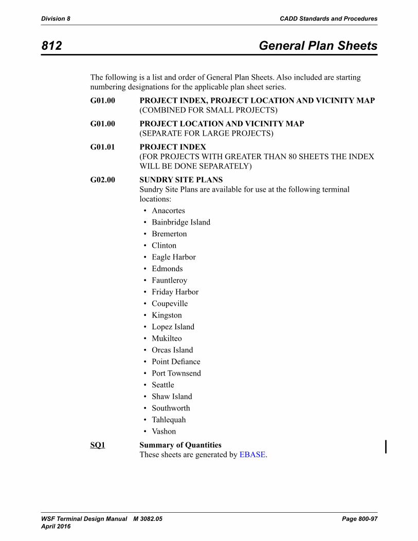
Division 8 CADD Standards and Procedures
WSF Terminal Design Manual M 3082.05 Page 800-97 April 2016
812 General Plan Sheets
The following is a list and order of General Plan Sheets. Also included are starting numbering designations for the applicable plan sheet series.
G01.00 PROJECT INDEX, PROJECT LOCATION AND VICINITY MAP (COMBINED FOR SMALL PROJECTS)
G01.00 PROJECT LOCATION AND VICINITY MAP (SEPARATE FOR LARGE PROJECTS)
G01.01 PROJECT INDEX (FOR PROJECTS WITH GREATER THAN 80 SHEETS THE INDEX WILL BE DONE SEPARATELY)
G02.00 SUNDRY SITE PLANS Sundry Site Plans are available for use at the following terminal locations:
• Anacortes• Bainbridge Island• Bremerton• Clinton• Eagle Harbor• Edmonds• Fauntleroy• Friday Harbor• Coupeville• Kingston• Lopez Island• Mukilteo• Orcas Island• Point Defiance• Port Townsend• Seattle• Shaw Island• Southworth• Tahlequah• Vashon
SQ1 Summary of Quantities These sheets are generated by EBASE.
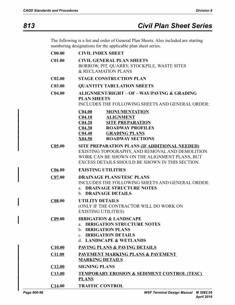
CADD Standards and Procedures Division 8
Page 800-98 WSF Terminal Design Manual M 3082.05 April 2016
813 Civil Plan Sheet Series
The following is a list and order of General Plan Sheets. Also included are starting numbering designations for the applicable plan sheet series.C00.00 CIVIL INDEX SHEETC01.00 CIVIL GENERAL PLAN SHEETS
BORROW, PIT, QUARRY, STOCKPILE, WASTE SITES & RECLAMATION PLANS
C02.00 STAGE CONSTRUCTION PLANC03.00 QUANTITY TABULATION SHEETSC04.00 ALIGNMENT/RIGHT – OF – WAY/PAVING & GRADING
PLAN SHEETS INCLUDES THE FOLLOWING SHEETS AND GENERAL ORDER:
C04.00 MONUMENTATION C04.10 ALIGNMENT C04.20 SITE PREPARATION C04.30 ROADWAY PROFILES C04.40 GRADING PLANS X04.50 ROADWAY SECTIONS
C05.00 SITE PREPARATION PLANS (IF ADDITIONAL NEEDED) EXISTING TOPOGRAPHY, AND REMOVAL AND DEMOLITION WORK CAN BE SHOWN ON THE ALIGNMENT PLANS, BUT EXCESS DETAILS SHOULD BE SHOWN IN THIS SECTION.
C06.00 EXISTING UTILITIESC07.00 DRAINAGE PLANS/TESC PLANS
INCLUDES THE FOLLOWING SHEETS AND GENERAL ORDER:a. DRAINAGE STRUCTURE NOTESb. DRAINAGE DETAILS
C08.00 UTILITY DETAILS (ONLY IF THE CONTRACTOR WILL DO WORK ON EXISTING UTILITIES)
C09.00 IRRIGATION & LANDSCAPEa. IRRIGATION STRUCTURE NOTESb. IRRIGATION PLANSc. IRRIGATION DETAILSd. LANDSCAPE & WETLANDS
C10.00 PAVING PLANS & PAVING DETAILSC11.00 PAVEMENT MARKING PLANS & PAVEMENT
MARKING DETAILSC12.00 SIGNING PLANSC13.00 TEMPORARY EROSION & SEDIMENT CONTROL (TESC)
PLANSC14.00 TRAFFIC CONTROL
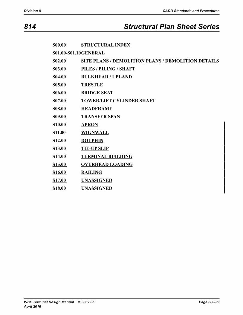
Division 8 CADD Standards and Procedures
WSF Terminal Design Manual M 3082.05 Page 800-99 April 2016
814 Structural Plan Sheet Series
S00.00 STRUCTURAL INDEX
S01.00-S01.10 GENERAL
S02.00 SITE PLANS / DEMOLITION PLANS / DEMOLITION DETAILS
S03.00 PILES / PILING / SHAFT
S04.00 BULKHEAD / UPLAND
S05.00 TRESTLE
S06.00 BRIDGE SEAT
S07.00 TOWER/LIFT CYLINDER SHAFT
S08.00 HEADFRAME
S09.00 TRANSFER SPAN
S10.00 APRON
S11.00 WIGNWALL
S12.00 DOLPHIN
S13.00 TIE-UP SLIP
S14.00 TERMINAL BUILDING
S15.00 OVERHEAD LOADING
S16.00 RAILING
S17.00 UNASSIGNED
S18.00 UNASSIGNED
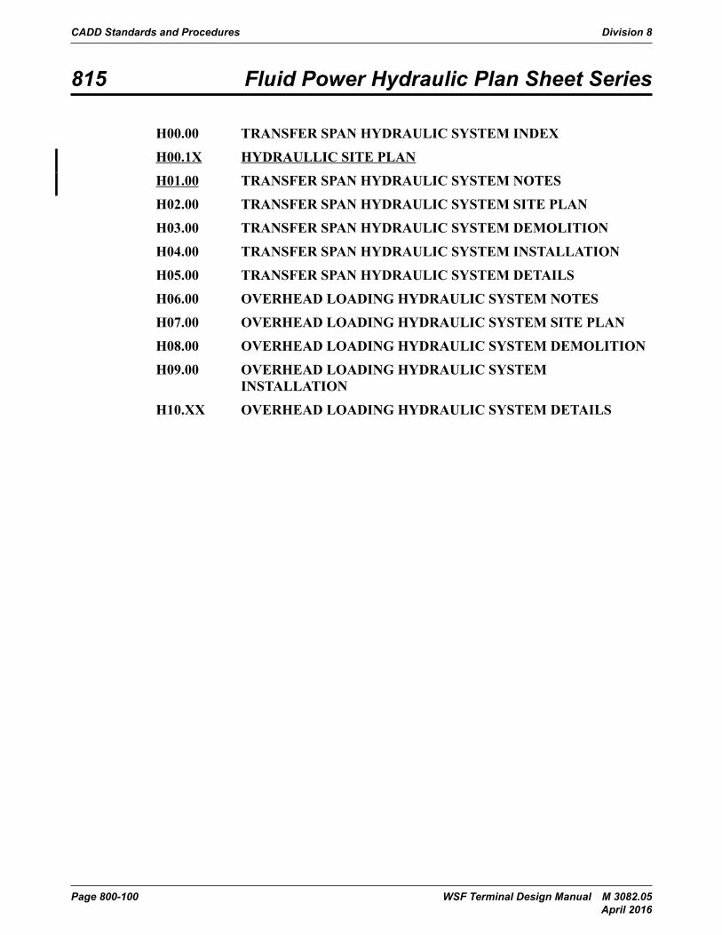
CADD Standards and Procedures Division 8
Page 800-100 WSF Terminal Design Manual M 3082.05 April 2016
815 Fluid Power Hydraulic Plan Sheet Series
H00.00 TRANSFER SPAN HYDRAULIC SYSTEM INDEX
H00.1X HYDRAULLIC SITE PLAN
H01.00 TRANSFER SPAN HYDRAULIC SYSTEM NOTES
H02.00 TRANSFER SPAN HYDRAULIC SYSTEM SITE PLAN
H03.00 TRANSFER SPAN HYDRAULIC SYSTEM DEMOLITION
H04.00 TRANSFER SPAN HYDRAULIC SYSTEM INSTALLATION
H05.00 TRANSFER SPAN HYDRAULIC SYSTEM DETAILS
H06.00 OVERHEAD LOADING HYDRAULIC SYSTEM NOTES
H07.00 OVERHEAD LOADING HYDRAULIC SYSTEM SITE PLAN
H08.00 OVERHEAD LOADING HYDRAULIC SYSTEM DEMOLITION
H09.00 OVERHEAD LOADING HYDRAULIC SYSTEM INSTALLATION
H10.XX OVERHEAD LOADING HYDRAULIC SYSTEM DETAILS
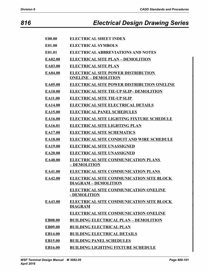
Division 8 CADD Standards and Procedures
WSF Terminal Design Manual M 3082.05 Page 800-101 April 2016
816 Electrical Design Drawing Series
E00.00 ELECTRICAL SHEET INDEX
E01.00 ELECTRICAL SYMBOLS
E01.01 ELECTRICAL ABBREVIATIONS AND NOTES
EA02.00 ELECTRICAL SITE PLAN – DEMOLITION
EA03.00 ELECTRICAL SITE PLAN
EA04.00 ELECTRICAL SITE POWER DISTRIBUTION ONELINE – DEMOLITION
EA05.00 ELECTRICAL SITE POWER DISTRIBUTION ONELINE
EA10.00 ELECTRICAL SITE TIE-UP SLIP– DEMOLITION
EA11.00 ELECTRICAL SITE TIE-UP SLIP
EA14.00 ELECTRICAL SITE ELECTRICAL DETAILS
EA15.00 ELECTRICAL PANEL SCHEDULES
EA16.00 ELECTRICAL SITE LIGHTING FIXTURE SCHEDULE
EA16.01 ELECTRICAL SITE LIGHTING PLAN
EA17.00 ELECTRICAL SITE SCHEMATICS
EA18.00 ELECTRICAL SITE CONDUIT AND WIRE SCHEDULE
EA19.00 ELECTRICAL SITE UNASSIGNED
EA20.00 ELECTRICAL SITE UNASSIGNED
EA40.00 ELECTRICAL SITE COMMUNICATION PLANS – DEMOLITION
EA41.00 ELECTRICAL SITE COMMUNICATION PLANS
EA42.00 ELECTRICAL SITE COMMUNICATION SITE BLOCK DIAGRAM – DEMOLITION
ELECTRICAL SITE COMMUNICATION ONELINE - DEMOLITION
EA43.00 ELECTRICAL SITE COMMUNICATION SITE BLOCK DIAGRAM
ELECTRICAL SITE COMMUNICATION ONELINE
EB08.00 BUILDING ELECTRICAL PLAN – DEMOLITION
EB09.00 BUILDING ELECTRICAL PLAN
EB14.00 BUILDING ELECTRICAL DETAILS
EB15.00 BUILDING PANEL SCHEDULES
EB16.00 BUILDING LIGHTING FIXTURE SCHEDULE
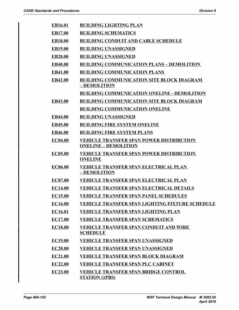
CADD Standards and Procedures Division 8
Page 800-102 WSF Terminal Design Manual M 3082.05 April 2016
EB16.01 BUILDING LIGHTING PLAN
EB17.00 BUILDING SCHEMATICS
EB18.00 BUILDING CONDUIT AND CABLE SCHEDULE
EB19.00 BUILDING UNASSIGNED
EB20.00 BUILDING UNASSIGNED
EB40.00 BUILDING COMMUNICATION PLANS – DEMOLITION
EB41.00 BUILDING COMMUNICATION PLANS
EB42.00 BUILDING COMMUNICATION SITE BLOCK DIAGRAM – DEMOLITION
BUILDING COMMUNICATION ONELINE - DEMOLITION
EB43.00 BUILDING COMMUNICATION SITE BLOCK DIAGRAM
BUILDING COMMUNICATION ONELINE
EB44.00 BUILDING UNASSIGNED
EB45.00 BUILDING FIRE SYSTEM ONELINE
EB46.00 BUILDING FIRE SYSTEM PLANS
EC04.00 VEHICLE TRANSFER SPAN POWER DISTRIBUTION ONELINE – DEMOLITION
EC05.00 VEHICLE TRANSFER SPAN POWER DISTRIBUTION ONELINE
EC06.00 VEHICLE TRANSFER SPAN ELECTRICAL PLAN – DEMOLITION
EC07.00 VEHICLE TRANSFER SPAN ELECTRICAL PLAN
EC14.00 VEHICLE TRANSFER SPAN ELECTRICAL DETAILS
EC15.00 VEHICLE TRANSFER SPAN PANEL SCHEDULES
EC16.00 VEHICLE TRANSFER SPAN LIGHTING FIXTURE SCHEDULE
EC16.01 VEHICLE TRANSFER SPAN LIGHTING PLAN
EC17.00 VEHICLE TRANSFER SPAN SCHEMATICS
EC18.00 VEHICLE TRANSFER SPAN CONDUIT AND WIRE SCHEDULE
EC19.00 VEHICLE TRANSFER SPAN UNASSIGNED
EC20.00 VEHICLE TRANSFER SPAN UNASSIGNED
EC21.00 VEHICLE TRANSFER SPAN BLOCK DIAGRAM
EC22.00 VEHICLE TRANSFER SPAN PLC CABINET
EC23.00 VEHICLE TRANSFER SPAN BRIDGE CONTROL STATION (1PBS)
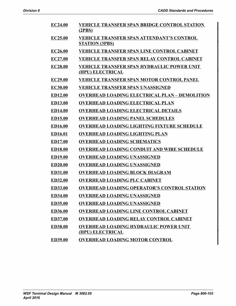
Division 8 CADD Standards and Procedures
WSF Terminal Design Manual M 3082.05 Page 800-103 April 2016
EC24.00 VEHICLE TRANSFER SPAN BRIDGE CONTROL STATION (2PBS)
EC25.00 VEHICLE TRANSFER SPAN ATTENDANT’S CONTROL STATION (3PBS)
EC26.00 VEHICLE TRANSFER SPAN LINE CONTROL CABINET
EC27.00 VEHICLE TRANSFER SPAN RELAY CONTROL CABINET
EC28.00 VEHICLE TRANSFER SPAN HYDRAULIC POWER UNIT (HPU) ELECTRICAL
EC29.00 VEHICLE TRANSFER SPAN MOTOR CONTROL PANEL
EC30.00 VEHICLE TRANSFER SPAN UNASSIGNED
ED12.00 OVERHEAD LOADING ELECTRICAL PLAN – DEMOLITION
ED13.00 OVERHEAD LOADING ELECTRICAL PLAN
ED14.00 OVERHEAD LOADING ELECTRICAL DETAILS
ED15.00 OVERHEAD LOADING PANEL SCHEDULES
ED16.00 OVERHEAD LOADING LIGHTING FIXTURE SCHEDULE
ED16.01 OVERHEAD LOADING LIGHTING PLAN
ED17.00 OVERHEAD LOADING SCHEMATICS
ED18.00 OVERHEAD LOADING CONDUIT AND WIRE SCHEDULE
ED19.00 OVERHEAD LOADING UNASSIGNED
ED20.00 OVERHEAD LOADING UNASSIGNED
ED31.00 OVERHEAD LOADING BLOCK DIAGRAM
ED32.00 OVERHEAD LOADING PLC CABINET
ED33.00 OVERHEAD LOADING OPERATOR’S CONTROL STATION
ED34.00 OVERHEAD LOADING UNASSIGNED
ED35.00 OVERHEAD LOADING UNASSIGNED
ED36.00 OVERHEAD LOADING LINE CONTROL CABINET
ED37.00 OVERHEAD LOADING RELAY CONTROL CABINET
ED38.00 OVERHEAD LOADING HYDRAULIC POWER UNIT (HPU) ELECTRICAL
ED39.00 OVERHEAD LOADING MOTOR CONTROL
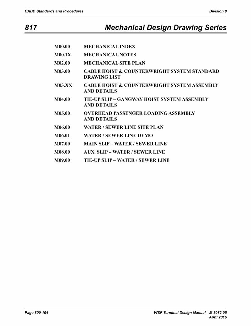
CADD Standards and Procedures Division 8
Page 800-104 WSF Terminal Design Manual M 3082.05 April 2016
817 Mechanical Design Drawing Series
M00.00 MECHANICAL INDEX
M00.1X MECHANICAL NOTES
M02.00 MECHANICAL SITE PLAN
M03.00 CABLE HOIST & COUNTERWEIGHT SYSTEM STANDARD DRAWING LIST
M03.XX CABLE HOIST & COUNTERWEIGHT SYSTEM ASSEMBLY AND DETAILS
M04.00 TIE-UP SLIP – GANGWAY HOIST SYSTEM ASSEMBLY AND DETAILS
M05.00 OVERHEAD PASSENGER LOADING ASSEMBLY AND DETAILS
M06.00 WATER / SEWER LINE SITE PLAN
M06.01 WATER / SEWER LINE DEMO
M07.00 MAIN SLIP – WATER / SEWER LINE
M08.00 AUX. SLIP – WATER / SEWER LINE
M09.00 TIE-UP SLIP – WATER / SEWER LINE