DIVISION 600 - codot.gov
201
601.01 601-1 DIVISION 600 MISCELLANEOUS CONSTRUCTION SECTION 601 STRUCTURAL CONCRETE DESCRIPTION 601.01 This work consists of furnishing and placing hydraulic cement concrete in accordance with these specifications and in conformity with the lines, grades, and dimensions as shown on the plans or established. This work includes preparing concrete surfaces designated in the Contract and applying an approved colored Structural Concrete Coating. 601.02 Classification. The classes of concrete shown in Table 601-1 shall be used when specified in the Contract. Table 601-1 CONCRETE FIELD REQUIREMENTS Concrete Class Required Field Compressive Strength (psi) Air Content: % Range (Total) Slump 2 Maximum Water/Cementitious Material Ratio: B 4500 at 28 days 5 - 8 +/- 2” of Form 1373 Slump w/cm on Form 1373 BZ 4000 at 28 days N/A 1 6” – 9” w/cm on Form 1373 D 4500 at 28 days 5 – 8 +/- 2” of Form 1373 Slump w/cm on Form 1373 DT 4500 at 28 days 5 – 8 +/- 2” of Form 1373 Slump w/cm on Form 1373 G 4500 at 28 days 5 – 8 +/- 2” of Form 1373 Slump w/cm on Form 1373 PS (Girders) 8500 at 28 days N/A 1 9” maximum 0.45 PS (Deck Panels) 6000 at 28 days N/A 1 9” maximum 0.45 P 4500 at 28 days 4 – 8 +/- 2” of Form 1373 Slump w/cm on Form 1373 S35 5000 at 28 days 5 – 8 +/- 2” of Form 1373 Slump w/cm on Form 1373 S40 5800 at 28 days 5 – 8 +/- 2” of Form 1373 Slump w/cm on Form 1373 S50 7250 at 28 days 5 – 8 +/- 2” of Form 1373 Slump w/cm on Form 1373 Shotcrete 4500 at 28 days 7-10 3 N/A 0.45 1 5 - 8% when specified 2 Slump shall be a maximum of 9.0 inches for all classes of concrete. Concrete may have a slump above 9.0 inches when designed as Self Consolidating Concrete (SCC). The requirements for slump flow, blocking assessment, and segregation shall apply. 3 Prior to pumping for wet process.
Transcript of DIVISION 600 - codot.gov

601.01
601-1
DIVISION 100DIVISION 600
MISCELLANEOUS CONSTRUCTION
Section 101SECTION 601
STRUCTURAL CONCRETE
DESCRIPTION
601.01 This work consists of furnishing and placing hydraulic cement concrete in accordance with these specifications and in conformity with the lines, grades, and dimensions as shown on the plans or established. This work includes preparing concrete surfaces designated in the Contract and applying an approved colored Structural Concrete Coating. 601.02 Classification. The classes of concrete shown in Table 601-1 shall be used when specified in the Contract.
Table 601-1 CONCRETE FIELD REQUIREMENTS
Concrete Class Required Field Compressive Strength (psi)
Air Content: % Range
(Total)
Slump2 Maximum
Water/Cementitious Material Ratio:
B 4500 at 28 days 5 - 8 +/- 2” of Form 1373 Slump w/cm on Form 1373
BZ 4000 at 28 days N/A1 6” – 9” w/cm on Form 1373
D 4500 at 28 days 5 – 8 +/- 2” of Form 1373 Slump w/cm on Form 1373
DT 4500 at 28 days 5 – 8 +/- 2” of Form 1373 Slump w/cm on Form 1373
G 4500 at 28 days 5 – 8 +/- 2” of Form 1373 Slump w/cm on Form 1373
PS (Girders) 8500 at 28 days N/A1 9” maximum 0.45
PS (Deck Panels) 6000 at 28 days N/A1 9” maximum 0.45
P 4500 at 28 days 4 – 8 +/- 2” of Form 1373 Slump w/cm on Form 1373
S35 5000 at 28 days 5 – 8 +/- 2” of Form 1373 Slump w/cm on Form 1373
S40 5800 at 28 days 5 – 8 +/- 2” of Form 1373 Slump w/cm on Form 1373
S50 7250 at 28 days 5 – 8 +/- 2” of Form 1373 Slump w/cm on Form 1373
Shotcrete 4500 at 28 days 7-103 N/A 0.45
1 5 - 8% when specified 2 Slump shall be a maximum of 9.0 inches for all classes of concrete. Concrete may have a slump above 9.0 inches when designed as Self Consolidating Concrete (SCC). The requirements for slump flow, blocking assessment, and segregation shall apply. 3 Prior to pumping for wet process.

601-2
Class B concrete is air-entrained concrete for general use. Class D, G, or P concrete may be substituted for Class B concrete. Additional requirements are:
(1) The coarse aggregate shall have a nominal maximum size of 1 1/2 inches or smaller. (2) Class B Concrete for Slope and Ditch Paving shall be macro-fiber reinforced. Class BZ concrete is concrete for drilled shafts. Additional requirements are: (1) Entrained air is not required unless specified in the Contract. When entrained air is specified in the Contract, the air
content shall be 5 to 8 percent. (2) Slump shall be a minimum of 6 inches and a maximum of 9 inches. A minimum slump of 6 inches shall be maintained
during the anticipated pour period. The use of retarders and hydration stabilizers are allowed to extend the slump life of the concrete. When the Contractor elects to use SCC, the slump requirement for Class BZ Concrete does not apply.
(3) The coarse aggregate size shall be AASHTO M43 size #8 unless otherwise approved by the Engineer. (4) The mix shall either have a permeability not exceeding 2,500 coulombs at an age of not more than 56 days when tested
in accordance with ASTM C1202, or have a surface resistivity of at least 12 kΩ-cm at 28 days using AASHTO T358. (5) The unrestrained shrinkage shall not exceed 0.050 percent at 28 days when tested by CP-L 4103. Class D concrete is a denser general use concrete. Class G may be substituted for Class D concrete. Additional requirements are: (1) The mix shall either have a permeability not exceeding 2,500 coulombs at an age of not more than 56 days when tested
in accordance with ASTM C1202, or have a surface resistivity of at least 12 kΩ-cm at 28 days using AASHTO T358. (2) The unrestrained shrinkage shall not exceed 0.050 percent at 28 days when tested by CP-L 4103. (3) The mix may use an optimized gradation (OG) with a nominal maximum aggregate size of at least ¾ inch. (4) The mix shall have a nominal maximum aggregate size of at least ¾ inch if an OG is not used. (5) When used in slip forming, an edge slump less than 6 mm (0.25 in.) and less than 30 percent surface voids (ranking of 2
or less) is required. The box test is described in CP 63. (6) Class D Concrete for sidewalks on bridge decks and bridge rail shall be macro-fiber reinforced.
Class DT concrete is used for bridge deck resurfacing. Additional requirements are:
(1) The concrete mix shall consist of a minimum of 50 percent AASHTO M 43 size No. 7 or No. 8 coarse aggregate by
weight of total aggregate. (2) The mix shall either have a permeability not exceeding 2,500 coulombs at an age of not more than 56 days when tested
in accordance with ASTM C1202, or have a surface resistivity of at least 12 kΩ-cm at 28 days using AASHTO T358. (3) The unrestrained shrinkage shall not exceed 0.050 percent at 28 days when tested by CP-L 4103.
Class G concrete is a low shrinkage macro fiber-reinforced concrete. Additional requirements are:
(1) The concrete mix shall include approved macro or hybrid polyolefin fibers at a minimum dosage of 4 lbs/cy or the
minimum dosage specified on the Department’s Approved Product List (APL), whichever is greater. (2) Shrinkage reducing admixtures may be incorporated into the mix. (3) The unrestrained shrinkage shall not exceed 0.030 percent at 28 days when tested by CP-L 4103. (4) The mix shall either have a permeability not exceeding 2,500 coulombs at an age of not more than 56 days when tested
in accordance with ASTM C1202, or have a surface resistivity of at least 12 kΩ-cm at 28 days using AASHTO T358. (5) The mix may use an OG with a nominal maximum aggregate size of at least 3/4 inch. The mix shall have a nominal
maximum aggregate size of at least 3/4 inch if an OG is not used. (6) An expansive cement additive may be added to an ASTM C150 Type I/II cement and fly ash to produce an ASTM C845
Type K cement. The proportion of the expansive cement additive will be determined by testing the cementitious material blend in accordance with ASTM C806. The blended material shall have an expansion of 0.04 to 0.10 percent at 7 days when tested in accordance with ASTM C806. When an expansive cement is used, the w/cm ratio shall be 0.45 to 0.55 and the expansion of the laboratory trial mix shall be 0.05 to 0.09 percent at 7 days when tested in accordance with ASTM C878.
Class P concrete is used in pavements. Additional requirements are: (1) The Required Field Flexural Strength shall be 650 psi. (2) The concrete mix shall consist of a minimum 55 percent AASHTO M 43 sizes No. 57, No. 6, No. 67, No. 357, or No.
467 coarse aggregate by weight of total aggregate. (3) The mix may use an OG with a nominal maximum aggregate size of at least ¾ inch.

601.03
601-3
(4) ASTM C150 Type III cement may be used for early opening. (5) The mix shall either have a permeability not exceeding 2,500 coulombs at an age of not more than 56 days when tested in
accordance with ASTM C1202, or have a surface resistivity of at least 12 kΩ-cm at 28 days using AASHTO T358. (6) The unrestrained shrinkage shall not exceed 0.050 percent at 28 days when tested by CP-L 4103. (7) When concrete is to be placed using a paver, an edge slump less than 6 mm (0.25 in.) and less than 30 percent surface voids
(ranking of 2 or less) is required. The box test is described in CP 63. (8) A minimum of 20 percent Class F fly ash or High Reactivity Pozzolan or 30 percent Slag cement by weight shall be used to
replace any ASTM C150 cement, or ASTM C595 Type IL cement. ASTM C595 Type IT(MS), IT(HS), IP(MS) or IP(HS) cements may be used without cement substitutions. Class C fly ash may be used if the calcium oxychloride is determined to be less than 15 g CaOXY/100 g cementitious paste as determined in accordance with AASHTO T 365 for Class 0 Sulfate Exposure.
Class PS Class PS concrete is used for prestressed concrete members. Requirements for Class PS concrete are specified in subsection 618.11. ASTM C150 Type III cement may be used. Class S35, S40, and S50 concretes are dense, high-strength concretes. Additional requirements are:
(1) The concrete mix shall be made with AASHTO M 43 sizes No. 57, No. 6, No. 67, No. 7, or No. 8 coarse aggregate. (2) When placed in a bridge deck, the mix shall have a nominal maximum aggregate size of at least 3/4 inch. (3) The mixes may use an OG with a nominal maximum aggregate size of at least 3/4 inch. (4) For S35 and S40 concretes, the unrestrained shrinkage shall not exceed 0.050 percent at 28 days when tested by CP-L 4103. (5) For S50 concretes, the unrestrained shrinkage shall not exceed 0.040 percent at 28 days when tested by CP-L 4103. (6) For S35 and S40 concretes, the mix shall either have a permeability not exceeding 2,000 coulombs at an age of not more than
56 days when tested in accordance with ASTM C1202, or have a surface resistivity of at least 14 kΩ-cm at 28 days using AASHTO T358.
(7) For S50 concrete, the mix shall either have a permeability not exceeding 1,500 coulombs at an age of not more than 56 days when tested in accordance with ASTM C1202, or have a surface resistivity of at least 18 kΩ-cm at 28 days using AASHTO T358.
Class Shotcrete concrete is used for shotcrete applications. Additional requirements are:
(1) The required air content prior to the pump for wet process applications shall be 7–10 percent. (2) Additional requirements are listed in subsection 641.02. The Contractor may design Class B, Class BZ, Class D, Class G, Class PS, Class S35, Class S40, and Class S50 concrete to be Self Consolidating Concrete (SCC) with the following requirements: (1) SCC shall have a slump flow of 20 to 26 inches when tested in accordance with ASTM C1611 using an inverted slump cone. (2) SCC shall have a maximum blocking assessment of 2.0 inches when tested in accordance with ASTM C1621. (3) SCC shall have a maximum static segregation of 10 percent when tested in accordance with ASTM C1610.
MATERIALS
601.03 Materials shall meet the requirements specified in the following subsections:
Fine Aggregate 703.01 Coarse Aggregate 703.02 Portland Cement 701.01 Fly Ash 701.02 Silica Fume 701.03 Water 712.01 Air Entraining Admixtures 711.02 Pigments and Admixtures 711.03 Curing Materials 711.01 Preformed Joint Material 705.01 Reinforcing Steel 709.01 Bearing Materials 705.06 Epoxy 712.10 Structural Concrete Coating 708.08 High-reactivity Pozzolans 701.04 Slag Cement 701.05

601-4
Pozzolans shall consist of fly ash, silica fume, and high-reactivity pozzolan. Prestressing steel shall meet the requirements of subsection 714.01 except as noted on the plans. Calcium Chloride shall not be used in reinforced concrete. Calcium Chloride shall be used in non-reinforced concrete only when specified. Where Fiber-Reinforced Concrete is specified or designated on the plans, the concrete mix shall include approved polyolefin fibers. Unless otherwise specified, a minimum of 1.5 pounds or the manufacturer’s recommended dose per cubic yard of polyolefin fiber reinforcement shall be evenly distributed into the mix. Mixing shall be as recommended by the manufacturer such that the fibers do not ball up. Polyolefin fibers shall meet the requirements of ASTM C1116 and ASTM D7508. Where Macro Fiber-Reinforced Concrete is specified or designated on the plans, the concrete mix shall include approved macro or hybrid polyolefin fibers at a minimum dosage of 4 lb/cy or the minimum dosage specified on the APL, whichever is greater. The dosage of the fiber may be reduced if trial mix data shows a minimum residual strength of 150 psi as determined in accordance with ASTM C1609 using a load support apparatus compliant with the requirements of ASTM C1812, “Standard Practice for Design of Journal Bearing Supports to be Used in Fiber Reinforced Concrete Beam Tests.” Mixing shall be as recommended by the manufacturer such that the fibers are evenly distributed in the mix and do not ball up. Macro or hybrid polyolefin fibers shall meet the requirements of ASTM C1116 and ASTM D7508.
601.04 Sulfate Resistance. The Contractor shall provide protection against sulfate attack on concrete structures and pavements by providing concrete manufactured according to the requirements of the specified Sulfate Exposure Class. The sulfate exposure class for all concrete except Class PS shall be Class 2 unless otherwise specified on the plans. The sulfate exposure class for Class PS shall be Class 0. The requirements for a higher sulfate exposure class may be used for lower sulfate exposure classes.
The Contractor may request to test the soil and water at a structure location to change the sulfate exposure class. Testing and sampling of the location shall be at a frequency approved by the Engineer, in consultation with the Region Materials Engineer. If the Contractor provided test reports that show another class of exposure exists at a structure location, the Engineer may accept a concrete mix for that location at the changed sulfate exposure class. Cementitious material requirements for each Sulfate Exposure Class are as follows: Class 0 requires that the concrete have a maximum Water/Cementitious Material Ratio of 0.45 and one of the following:
(1) ASTM C150 Type I, II, III, or V
(2) ASTM C595 Type IL, IP, IP(MS), IP(HS), or IT
Class 1 requires that the concrete have a maximum Water/Cementitious Material Ratio of 0.45 and one of the following:
(1) ASTM C150 Type II or V
(2) ASTM C595 Type IP(MS) or IP(HS)
(3) ASTM C150 Type III. Type III shall have no more than 8 percent C3A.
(4) ASTM C595 Type IL(MS), IL(HS), IT(MS), or (HS)
Class 2 requires that the concrete have a maximum Water/Cementitious Material Ratio of 0.45 and one of the following:
(1) ASTM C150 Type V with a minimum of a 20 percent substitution of Class F fly ash or slag cement by weight
(2) ASTM C150 Type II or III with a minimum of a 20 percent substitution of Class F fly ash, High-Reactivity Pozzolan, or slag cement by weight. The Type II or III cement shall have no more than 0.040 percent expansion at 14 days when tested according to ASTM C452.
(3) A blend of portland cement meeting ASTM C150 Type II or III with a minimum of 20 percent Class F fly ash, High-Reactivity Pozzolan, or slag cement by weight, where the blend has less than 0.05 percent expansion at 6 months or 0.10 percent expansion at 12 months when tested according to ASTM C1012

601.04
601-5
(4) ASTM C595 Type IP(HS), IL(HS), or IT(HS). Class F fly ash, slag cement, or High-Reactivity Pozzolan may be substituted for Type IL cement.
(5) ASTM C595 Type IL(MS) or IT(MS) plus Class F fly ash, slag cement, or High-Reactivity Pozzolan where the blend has less than 0.05 percent expansion at 6 months or 0.10 percent expansion at 12 months when tested according to ASTM C1012
Class 3 requires that the concrete have a maximum Water/Cementitious Material Ratio of 0.40 and one of the following: (1) A blend of portland cement meeting ASTM C150 Type II, III, or V with a minimum of a 20 percent substitution of Class F
fly ash, High-Reactivity Pozzolan, or slag cement by weight, where the blend has less than 0.10 percent expansion at 18 months when tested according to ASTM C1012
(2) ASTM C595 Type IL(MS) or IT(MS) plus High-Reactivity Pozzolan where the blend has less than 0.10 percent expansion at 18 months when tested according to ASTM C1012
(3) ASTM C595 Type IP(HS), IL(HS), or IT(HS) having less than 0.10 percent expansion at 18 months when tested according to ASTM C1012. Class F fly ash, slag cement, or High-Reactivity Pozzolan may be substituted for Type IL cement.
(4) ASTM C595 Type IL with a minimum of a 20 percent substitution of Class F fly ash or slag cement by weight, where the blend has less than 0.10 percent expansion at 18 months when tested according to ASTM C1012
(5) ASTM C150 Type I, II, III, or V plus a minimum of 20 percent Class F fly ash when the R factor of the fly ash is less than 0.75. R factor is determined using the following from the chemical composition of the fly ash:
32
5OFe
CaOR −=
ASTM C150 Type III cement may only be used in Class P or PS Concrete when approved by the Engineer. Class C fly ash shall not be substituted for cement when Class 1, 2, or 3 sulfate resistance/exposure class is specified. The maximum Water/Cementitious Material Ratio may be exceeded when an expansive cement additive is used. When fly ash or high-reactivity pozzolan is used to enhance sulfate resistance, it shall be used in a proportion greater than or equal to the proportion tested in accordance to ASTM C1012, shall be the same source, and shall have a calcium oxide content no more than 2.0 percent greater than the fly ash or high-reactivity pozzolan tested according to ASTM C1012. ASTM C1012 test results are acceptable for up to two years from the completion date of the test.
Table 601-2
Water-Soluble Sulfate (SO4) in Dry
Soil, (%)
Sulfate (SO4) in Water, ppm
Sulfate Exposure
Class
0.00 to 0.10 0 to 150 Class 0 0.11 to 0.20 151 to 1,500 Class 1 0.21 to 2.00 1,501 to 10,000 Class 2
2.01 or greater 10,001 or greater Class 3

601-6
CONSTRUCTION REQUIREMENTS
601.05 Mix Design Submittal Requirements. The Contractor shall submit a Concrete mix design for each class of concrete being placed on the project. Concrete shall not be placed on the project before the Concrete mix design has been approved by the Engineer. The Concrete mix design will be reviewed following the procedures of CP 62. The Concrete mix design will not be approved when the laboratory trial mix data or aggregate data are the results from tests performed more than two years in the past. The concrete mix design shall show the weights and sources of all materials including cements, pozzolans, aggregates, fibers, pigments, water, additives, and the water to cementitious material ratio (w/cm). When determining the w/cm, the weight of cementitious material (cm) shall be the sum of the weights of the cement, slag cement, fly ash, silica fume, and high-reactivity pozzolan. Water from dosages of admixtures greater than 10 ounces per 100 pounds of cementitious materials shall be included in the calculation of w/cm.
The laboratory trial mix data shall include results of the following:
(1) AASHTO T 119 (ASTM C143) Slump of Hydraulic Cement Concrete, except when the concrete is SCC
(2) AASHTO T 121 (ASTM C138) Weight per Cubic Foot, Yield, and Air Content (Gravimetric) of Concrete
(3) AASHTO T 152 (ASTM C231) Air Content of Freshly Mixed Concrete by the Pressure Method
(4) ASTM C39 Compressive Strength of Cylindrical Concrete Specimens shall be performed with at least two specimens at 7 days and three specimens at 28 days.
(5) Class P concrete shall include AASHTO T97 (ASTM C78) Flexural Strength of Concrete (Using Simple Beam with Third-Point Loading). At least two specimens will be tested at 7 days and four specimens at 28 days. The lab trial mix shall produce a flexural strength at 28 days of at least 650 psi.
(6) Concrete with an OG shall indicate the gradation of the blended aggregates. Optimized gradations shall be developed by an approved mix design technique such as Tarantula Curve, Shilstone, or KU mix.
(7) SCC concrete shall include ASTM C1611 Standard Test Method for Slump Flow of Self-Consolidating Concrete. Slump flow shall be measured using an inverted slump cone.
(8) SCC concrete shall include ASTM C1621 Standard Test Method for Passing Ability of Self-Consolidating Concrete by J-Ring.
(9) SCC concrete shall include ASTM C1610 Standard Test Method for Static Segregation of Self-Consolidating Concrete Using Column Technique.
(10) When concrete is to be placed using a paver, the edge slump and surface voids shall be reported in accordance with CP 63.
Prior to placement of accelerated Class P Concrete, the Contractor shall provide the Engineer a report of maturity relationships in accordance with CP 69. Except for Class PS concrete, the laboratory trial mix must produce an average compressive strength of at least the required field compressive strength specified in Table 601-1. For Class PS concrete, the laboratory trial mix must produce an average compressive strength of at least 115 percent of the required field compressive strength specified in Table 601-1. When entrained air is specified in the Contract for Class BZ concrete, the trial mix shall be run with the required air content. The laboratory trial mix shall have a relative yield of 0.99 to 1.02. Aggregate data shall include the results of the following:
(1) AASHTO T 11 (ASTM C117) Materials Finer Than 75 um (No. 200) Sieve in Mineral Aggregates by Washing
(2) AASHTO T 19 (ASTM C29) Unit Weight and Voids in Aggregate
(3) AASHTO T 21 (ASTM C40) Organic Impurities in Fine Aggregate for Concrete
(4) AASHTO T 27 (ASTM C136) Sieve Analysis of Fine and Coarse Aggregates
(5) AASHTO T 84 (ASTM C128) Specific Gravity and Absorption of Fine Aggregate

601.05
601-7
(6) AASHTO T 85 (ASTM C127) Specific Gravity and Absorption of Coarse Aggregate
(7) AASHTO T 96 (ASTM C131) Resistance to Degradation of Small-Size Coarse Aggregate by Abrasion and Impact in the Los Angeles Machine
(8) AASHTO T 104 (ASTM C88) Soundness of Aggregate by Use of Sodium Sulfate or Magnesium Sulfate
(9) CP 37 Plastic Fines in Graded Aggregates and Soils by use of the Sand Equivalent Test
(10) ASTM C535 Resistance to Degradation of Large-Size Coarse Aggregate by Abrasion and Impact in the Los Angeles Machine
(11) ASTM C1260 Determining the Potential Alkali Reactivity of Aggregates (Accelerated Mortar-Bar Method). When an aggregate source is known to be reactive, ASTM C1567 results may be submitted in lieu of ASTM C1260 results.
Aggregate tested by ASTM C1260 with an expansion of 0.10 percent or more, or that is known to be reactive, shall not be used unless mitigative measures are included in the mix design. Mitigative measures shall be tested using ASTM C1567 and exhibit an expansion less than 0.10 percent by one of the following methods: (1) Combined Aggregates. The mix design sources of aggregates, cement, and mitigative measures shall be tested. The
proportions of aggregates, cement, and mitigative measures shall be those used in the mix design.
(2) Individual Aggregates. Each source and size of individual aggregates shall be tested. The source of cement and mitigative measures shall be those used in the mix design. The highest level of mitigative measures for any individual aggregate shall be the minimum used in the mix design.
For all concrete mix designs with ASTM C150 and ASTM C595 Type IL cements, the total substitution of cement shall not exceed 50 percent by weight of total cementitious material. For all concrete mix designs with ASTM C595 Type IP, IP(MS), IP(HS), or IT cements: fly ash or high-reactivity pozzolan shall not be substituted for cement. For all concrete mix designs with ASTM C595 IT cements, slag cement shall not be substituted for cement. For all concrete mix designs with ASTM C595 Type IP, IP(MS), IP(HS) cements, when slag cement is substituted for cement, the total substitution of cement shall not exceed 50 percent by weight of total cementitious material. The Contractor shall submit a new Concrete Mix Design Report meeting the above requirements when a change occurs in the source, type, or proportions of cement, slag cement, fly ash, high-reactivity pozzolan, silica fume, or aggregate. Addition, removal, change of source, dosage change, or type of fibers to an approved mix design shall require a new mix design. Adjustments to aggregate weights may be made to adjust yield if the combined gradation remains constant (+/-1 percent) or within the optimized band. When a change occurs in the source or type of approved admixtures or the addition of approved accelerating, retarding, or hydration stabilizing admixtures to existing mix designs, the Contractor shall submit a letter stamped by the Concrete Mix Design Engineer approving the changes to the existing mix design. The change shall be approved by the Engineer prior to use. Unless otherwise permitted by the Engineer, the product of only one type of hydraulic cement from one source of any one brand shall be used in a concrete mix design. Approval of the concrete mix design by the Engineer does not constitute acceptance of the concrete. Acceptance will be based solely on the test results of concrete placed on the project. Once approved for a project, the mix design may be used for the duration of the project.

601-8
601.06 Batching Measuring and batching of materials shall be done in accordance with AASHTO M 157 (ASTM C94).
The Contractor shall furnish a batch ticket (delivery ticket) with each load for all classes of concrete. Concrete delivered without a batch ticket containing complete information as specified shall be rejected. The Contractor shall collect and complete the batch ticket at the placement site and deliver all batch tickets to the Engineer on a daily basis. The Engineer shall have access to the batch tickets at any time during the placement. The following information shall be provided on each batch ticket: (1) Supplier’s name and date
(2) Truck number
(3) CDOT Project number and location
(4) Concrete class designation and item number
(5) Cubic yards batched
(6) Time batched
(7) CDOT mix design number
(8) Type, brand, and amount of each admixture and pigment
(9) Type, brand, and amount of cement, slag cement, fly ash, and high-reactivity pozzolan
(10) Weights of fine and coarse aggregates or combined weight when an OG is pre-blended
(11) Moisture of fine and coarse aggregates or combined moisture when an OG is pre-blended
(12) Gallons (Pounds) of batch water (including ice)
(13) Weight of polyolefin fiber reinforcement
The Contractor shall add the following information to the batch ticket at the placement site:
(14) Gallons of water added by the truck operator, the time the water was added, and the quantity of concrete in the truck each
time water is added
(15) Number of revolutions of the drum at mixing speed (for truck mixed concrete)
(16) Discharge time
(17) Location of the batch in placement
(18) Water to cementitious material ratio
Electronic tickets are allowed as long as CDOT has access to the batch ticket and the batch ticket can be downloaded and saved by the Engineer in PDF format before placement, at any time during placement, and until the project is accepted.
(a) Hydraulic Cement, Fly Ash, High-Reactivity Pozzolan, Slag Cement and Silica Fume. All cementitious material shall be measured by mass. Supplementary cementitious materials may be weighed cumulatively with cement. Cement and other cementitious material shall be weighed on a scale and in a weigh hopper, which is separate and distinct from those used for other materials. When the quantity of cementitious material exceeds 30 percent of the full capacity of the scale, the quantity of cement and the cumulative quantity of cement plus supplementary cementitious material shall be within plus or minus 1 percent of the required mass. For small batches to a minimum of 1 cubic yard, the quantity of cement and the quantity of cement plus supplementary cementitious material used shall not be less than the required amount or more than 4 percent in excess. A fraction of a bag of cement shall not be used unless weighed. (b) Water. Mixing water shall consist of water added to the batch, ice added to the batch, water occurring as surface moisture on the aggregates, and water introduced in the form of admixtures. The added water shall be measured by mass or volume to an accuracy of 1 percent of the required total mixing water. Added ice shall be measured by weight. In the case of truck mixers, wash water retained in the drum for use in the next batch of concrete shall be accurately measured or shall be discharged prior to loading the next batch of concrete. Total water (including any wash water) shall be measured or weighed to an accuracy of ±3 percent.
601.07
601-9
(c) Aggregates. Aggregates from different sources and of different gradings shall not be stockpiled together. Aggregate shall be handled from stockpiles or other sources to the batching plant in such a manner as to secure a uniform grading of the material. Aggregates that have become segregated, or mixed with earth or foreign material, shall not be used. All aggregates produced or handled by hydraulic methods, and washed aggregates, shall be stockpiled or binned for draining at least 12 hours before being batched. Rail shipment requiring more than 12 hours will be accepted as adequate binning only if the car bodies permit free drainage. In case the aggregates contain high or non-uniform moisture content, storage or stockpile period in excess of 12 hours may be required. Aggregate shall be measured by mass. The quantity of aggregate used in any batch of concrete as indicated by the scale shall be within ±2 percent of the required mass when weighed in individual weigh batchers. In a cumulative aggregate weigh batcher, the cumulative mass after each successive weighing shall be within plus or minus 1 percent of the required cumulative amount when the scale is used in excess of 30 percent of its capacity. For cumulative mass for less than 30 percent of scale capacity, the tolerance shall be plus or minus 0.3 percent of scale capacity or plus or minus 3 percent of the required cumulative mass, whichever is less. (d) Bins and Scales. The batching plant may include bins, weighing hoppers, and scales for the fine aggregate and for each size of coarse aggregate. A bin, hopper, and scale for cementitious material shall be included. A single weighing hopper with an accumulative scale will be permitted, provided a separate scale is used for weighing cementitious material. Scales shall meet the requirements of subsection 109.01. 601.07 Mixing. Mixing of materials shall be done in accordance with AASHTO M 157 (ASTM C94). Concrete shall be mixed in stationary mixers, in a central mix plant, in truck mixers, or in self-contained mobile mixers. Mixing time shall be measured from the time all materials, except water, are in the drum.
Admixtures listed in the mix design, or admixtures approved in accordance with subsection 601.04 and water may be added at the project. (a) Mixing General. Concrete shall be deposited in place within 90 minutes after batching when concrete is delivered in truck
mixers or agitating trucks, and within 60 minutes when delivered in non-agitating trucks.
The 90-minute time limit for a mixer or agitating trucks may be extended to 120 minutes if: (1) No water is added after 90 minutes.
(2) The concrete temperature prior to placement is less than 90 °F.
The 90-minute time limit for a mixer or agitating trucks may be extended to 180 minutes if: (1) No water is added after 90 minutes.
(2) The concrete temperature prior to placement is less than 90 °F.
(3) The approved concrete mix contains an approved retarding admixture.
The 90-minute time limit for a mixer or agitating trucks may be extended longer than 180 minutes if: (1) An Extended Set Control Admixture (ESCA) is added at the time of batching. Procedures and doses shall be in
accordance with manufacturer’s recommendations. The ESCA shall be on the approved products list.
(2) The concrete temperature prior to placement is less than 90 °F.
(3) Each load of concrete shall be sampled and tested by the Contractor for air content according to CP 61.
(4) The Department will cast three additional acceptance cylinders. If the acceptance cylinders tested at 28 days do not meet design strength, the additional cylinders will be tested at 56 days for acceptance.

601-10
(b) Central-Mixed Concrete. Concrete that is mixed completely in a stationary mixer and transported to the point of delivery either in a truck agitator or a truck mixer operating at agitating speed, or in non-agitating equipment approved by the Engineer, shall conform to the following:
(1) The mixing time shall be counted from the time all the solid materials are in the drum.
(2) The batch shall be so charged into the mixer so that some water will enter in advance of the cement and aggregate.
(3) All water shall be in the drum by the end of the first one-fourth of the specified mixing time.
(4) The volume of concrete mixed per batch may exceed the mixer's nominal capacity, as shown on the manufacturer’s standard rating plate on the mixer, by up to 10 percent provided concrete test data for strength, segregation, and uniform consistency are satisfactory, and provided spillage of concrete does not occur.
(5) Where no mixer uniformity tests are made, the acceptable mixing time for mixers having capacities of 1 cubic yard or less shall be not less than 1 minute. For mixers of greater capacity, this minimum shall be increased 15 seconds for each cubic yard or fraction thereof of additional capacity. Uniformity testing shall be in accordance with AASHTO M157 (ASTM C94).
(c) Truck Mixing. Truck mixed concrete shall conform with one of the following:
(1) Concrete that is completely mixed in a truck mixer shall be mixed 70 to 100 revolutions at the mixing speed to produce uniform concrete. Concrete uniformity tests shall be made in accordance with AASHTO M157 (ASTM C94). Additional revolutions of the mixer beyond the number found to produce the required uniformity of concrete shall be at a designated agitating speed.
(2) For concrete that is partially mixed in a stationary mixer, and then mixed completely in a truck mixer (shrink mixed concrete), the time of partial mixing shall be the minimum required to intermingle the materials. After transfer to a truck mixer, it shall be mixed at a speed to produce uniform concrete. Concrete uniformity tests shall be made in accordance with AASHTO M157 (ASTM C94). Additional revolutions of the mixer beyond the number found to produce the required uniformity of concrete shall be at a designated agitating speed.
(3) Concrete mixed entirely in a stationary mixer and delivered to the job in a truck mixer shall be remixed for a minimum of 20 revolutions of the mixing drum at mixing speed at the job site prior to discharge.
When water is added at the delivery site to control the consistency of the concrete, the concrete shall be mixed for at least 30 revolutions of the mixer drum at mixing speed for each addition of water before discharge. These revolutions are in addition to the minimum revolutions required for mixing at the delivery site. The added water shall not cause the w/cm ratio to exceed the approved mix design w/cm ratio. Water from all sources shall be documented by the Contractor on the delivery slip for each load of concrete. The Contractor shall provide a Concrete Truck Mixer Certification. This certification shall show the various pick-up and throw-over configurations and wear marks so that the wear on the blades can be checked. Blades shall be replaced when any part or section is worn 1 inch or more below the original height of the manufacturer's design. A copy of the manufacturer's design, showing the dimensions and arrangement of blades, shall be available to the Engineer at all times. The Contractor shall furnish a water-measuring device in good working condition, mounted on each transit mix truck, for measuring the water added to the mix after the truck has left the charging plant. Each measuring device shall be equipped with an easy-to-read gauge. Water shall be measured to an accuracy of plus or minus 3 percent.
(d) Self Contained Mobile Mixer. Proportioning and mixing equipment shall be of the self-contained, mobile, continuous
mixing type in accordance with ASTM C685 and subject to the following:
(1) The mixer shall be self-propelled and capable of carrying sufficient unmixed dry, bulk cementitious materials, fine aggregate, coarse aggregate, admixtures, and water to produce on the site at least 6 cubic yards of concrete. The mixer shall have one bin for each size aggregate.
(2) The mixer shall be capable of positive measurement of cementitious materials being introduced into the mix. A
recording meter visible at all times and equipped with a ticket printout shall indicate the quantity of total concrete mix.
(3) The mixer shall provide positive control of the flow of water into the mixing chamber. Water flow shall be indicated
by a flow meter and be readily adjustable to provide for minor variations in the aggregate moisture.

601.08
601-11
(4) The mixer shall be capable of calibration to automatically proportion and blend all components of indicated composition
on a continuous or intermittent basis as required by the finishing operation, and shall discharge mixed material through a conventional chute directly in front of the finishing machine.
(5) The Contractor shall perform calibration tests according to the equipment manufacturer's recommendations at the
beginning of each project, and when there is a change in the mix design proportions or source of materials. The Engineer may require a calibration test or yield check when a change in the characteristics of the mixture is observed. The tolerances in proportioning the various materials shall be according to ASTM C685.
601.08 Air Content Adjustment. When a batch of concrete delivered to the project does not conform to the minimum specified air content, an air-entraining admixture conforming to subsection 711.02 may be added in accordance with subsection 601.17. After the admixture is added, the concrete shall be re-mixed for a minimum of 20 revolutions of the mixer drum at mixing speed. The concrete shall then be re-tested by PC. 601.09 Forms.
(a) Design. Forms shall be mortar tight and sufficiently rigid to prevent distortion due to the pressure of the concrete and other loads incidental to the concrete operations, including vibration.
The rate of depositing concrete in forms shall be controlled to prevent deflections of the form panels in excess of the deflections permitted by these specifications.
Forms for exposed concrete surfaces shall be designed and constructed so that the formed surface of the concrete does not undulate excessively in any direction between studs, joists, form stiffeners, form fasteners, or wales. Undulations exceeding 3/32 inch between the center-to-center distance of studs, joists, form stiffeners, form fasteners, or wales will be considered excessive. Should any form or forming system, even though previously approved for use, produce a concrete surface with excessive undulations, its use shall be discontinued until modifications satisfactory to the Engineer have been made. Portions of concrete structures with surface undulations in excess of the limits herein may be rejected by the Engineer.
Forms for drainage inlets may be constructed of any suitable material that will produce a structure with the inside dimensions and at least the wall thicknesses shown on the plans. Undulations of finished interior wall surfaces shall not exceed 0.5 inch.
Where called for in the Contract, the Contractor shall design and construct a permanent bridge deck forming system. Based on what is indicated, the Contractor will be permitted one of the following sets of options:
(1) If the plans indicate that permanent deck forms are optional, the Contractor shall have the option of constructing a cast-in-place bridge deck using conventional forms, a full-depth cast-in-place bridge deck using permanent steel bridge deck forms, or a partial depth cast-in-place bridge deck using precast panel deck forms as a portion thereof.
(2) If the plans indicate that permanent deck forms are required, the Contractor shall have the option of constructing a full depth cast-in-place bridge deck using permanent steel bridge deck forms, or a partial depth cast-in-place bridge deck using precast panel deck forms as a portion thereof.
(3) If the plans indicate that precast panel deck forms are required, the Contractor shall construct a partial depth cast-in-place bridge deck using precast panel deck forms as a portion thereof.
When SCC is used, forms shall be designed for loads as defined in ACI 347. Design calculations and form details shall be provided to the Engineer per Working Drawing requirements as defined in subsection 105.02.
(b) Construction. Forms shall be constructed and maintained so as to prevent the opening of joints due to shrinkage of the lumber. The use of ties consisting of twisted wire loops to hold forms in position will not be permitted. Deck slab forms between girders shall be constructed with no allowance for settlement relative to the girders.
The inside surfaces of forms shall be cleaned of all dirt, mortar, and foreign material. Forms that will later be removed shall be thoroughly coated with form oil prior to use. The form oil shall be a commercial quality form oil or other equivalent coating that will permit the ready release of the forms and will not discolor the concrete.
Concrete shall not be deposited in the forms until all work connected with constructing the forms has been completed; all materials required to be embedded in the concrete have been placed, unless otherwise specified on the plans or approved; and the Engineer has inspected said forms and material. Such work shall include the removal of all dirt, chips, sawdust, water, and other foreign material from the forms.

601-12
Anchor devices may be cast into the concrete for later use in supporting forms or for lifting precast members. The use of driven types of anchorages for fastening forms or form supports to concrete will not be permitted.
Backforms may be omitted with the approval of the Engineer in cases involving footings that can be placed in the dry without the use of cribs or cofferdams. In such cases, the entire excavation shall be filled with concrete to the required elevation of the top of the footing. The additional concrete required shall be placed at the expense of the Contractor, except when footings are poured out to rock. Extra concrete required to pour footings out to rock will be allowed in the concrete quantities, provided that no allowance will be made for any concrete extending more than 6 inches in any direction beyond the neat lines of the footings as shown on the plans.
Forms for the placement of deck concrete or other concrete work associated with structural steel girders shall be constructed so that any concentrated loads applied to girder webs shall be within 6 inches of a flange or stiffener. Where loads are applied to steel girder webs, they shall be applied in a manner that will not produce distortion to the web.
For structural steel girders, temporary struts and ties shall be provided as necessary to resist lateral loads applied to the girder flanges and to prevent appreciable relative movement between the edge of deck form and the adjacent steel girder.
When SCC is used, forms shall be constructed and maintained to meet aesthetic or smoothness criteria for the project. Form material other than plywood may be required.
(c) Form Lumber. Form lumber for all exposed concrete surfaces shall be dressed at least on one side and two edges and shallbe constructed so as to produce mortar-tight joints and smooth, even concrete surfaces. Forms shall be filleted andchamfered as shown on the plans, and shall be given a bevel or draft in the case of all projections, such as girders andcopings, to assure easy removal.
Unless otherwise specified, forms for exposed surfaces shall be constructed with triangular fillets 3/4 inch by 3/4 inch atall exterior corners.
(d) Metal Ties. Metal ties or anchorages within the forms shall be so constructed as to permit their removal to a depth of atleast 1/2 inch from the face without injury to the concrete. When wire ties are used, the wires shall be cut back at least1/4 inch from the face of the concrete upon removal of the forms. The cavities shall be filled with cement mortar and thesurface left sound, smooth, even, and uniform in color.
(e) Walls. Where the bottom of the forms is inaccessible, the lower form boards shall be left loose or other provisions madeso that extraneous material may be removed from the forms immediately before placing the concrete.
(f) Surface Treatment. All forms shall be treated with oil prior to placing reinforcement except that an approved non-petroleum base form release agent shall be used for surfaces that are to receive Class 5, Masonry Coating Finish. Woodforms shall be thoroughly moistened with water immediately before placing the concrete.
For rail members or other members with exposed faces, the forms shall be treated with an approved form release agent toprevent the adherence of concrete. Material that will adhere to or discolor the concrete shall not be used.
All concrete forms for surfaces to which Structural Concrete Coating is to be applied shall be treated with a water-basedconcrete form release agent prior to placing reinforcement.
(g) Metal Forms for General Use. The specifications for forms, regarding design, mortar tightness, filleted corners, beveledprojections, bracing, alignment, removal, reuse, and oiling, apply to metal forms. The metal used for forms shall be ofsuch thickness that the forms will remain true to shape. All bolt and rivet heads shall be countersunk. Clamps, pin,s orother connecting devices shall be designed to hold the forms rigidly together and to allow removal without injury to theconcrete. Metal forms that do not present a smooth surface or do not line up properly shall not be used. Metal forms shallbe free from rust, greas,e or other foreign matter. Permanent steel bridge deck forms shall be as described in subsection601.10.
(h) Removal of Forms. The forms for any portion of the structure shall not be removed until the concrete is strong enough towithstand damage when the forms are removed.
Unless specified in the plans, forms shall remain in place for members that resist dead load bending until the concretehas reached a compressive strength of at least 80 percent of the required 28-day strength, 0.80f ′c. Forms for columnsshall remain in place until the concrete has reached a compressive strength of at least 1,000 psi. Forms for sides ofbeams, walls, or other members that do not resist dead load bending shall remain in place until the concrete has reached acompressive strength of at least 500 psi.

601.10
601-13
Forms and supports for cast-in-place concrete box culverts (CBCs) shall not be removed until the concrete compressive strength exceeds 0.6f ′c. for CBCs with spans up to and including 12 feet, and 0.67f ′c. for CBCs with spans exceeding 12 feet but not larger than 20 feet. Forms for CBCs with spans larger than 20 feet shall not be removed until after all concrete has been placed in all spans and has attained a compressive strength of at least 0.80f ′c.
Concrete compressive strength shall be determined by maturity meters in accordance with CP 69. At the Pre-pour Conference, the Contractor shall submit the location where maturity meters will be placed.
The Contractor shall provide maturity meters and all necessary wires and connectors. The Contractor shall be responsible for the placement and maintenance of the maturity meter and wire. At a minimum, a maturity meter shall be placed at the mid-span of beams and at support locations. Placement shall be as directed by the Engineer. For structures with multiple maturity meters, the lowest compressive strength shall determine when the forms can be removed.
Acceptance cylinders shall not be used for determining compressive strength to remove forms.
When field operations are controlled by maturity meters, the removal of forms, supports, and housing and the discontinuance of heating and curing may begin when the concrete is found to have the required compressive strength.
Forms for the median barrier, railing, or curbs may be removed at the convenience of the Contractor after the concrete has hardened.
All forms shall be removed except permanent steel bridge deck forms and forms used to support hollow abutments or hollow piers when no permanent access is available into the cells. When permanent access is provided into box girders, all interior forms, falsework, and loose material shall be removed, and the inside of box girders shall be cleaned with an industrial vacuum.
When ESCAs are used, the removal of forms, supports and housing, and the discontinuance of heating and curing may begin when the concrete is found to have the required compressive strength.
(i) Patching. The mixed formula for patch mortar shall be determined by trial to obtain a good color match with the concrete when both patch and concrete are cured and dry.
(j) Re-use of Forms. The shape, strength, rigidity, water-tightness, and surface smoothness of reused forms shall be maintained at all times. Warped or bulged lumber shall not be used.
(k) Precast Panel Deck Forms. Working drawings for precast panel deck forms shall be submitted to the Engineer in conformity with subsection 105.02.
Prestressing for precast panel deck forms shall be in accordance with subsection 618.07(a).
Concrete for precast panel deck forms shall be cured in accordance with subsection 618.12.
Precast panel deck forms shall be stored and transported in a horizontal position and shall conform to the requirements of subsections 618.14(c) and 618.15.
When precast panels are erected, the fit of mating surfaces shall have no more than a 1/8 inch gap to prevent concrete leakage. If such fit cannot be provided, the joint shall be filled with grout or sealed with an acceptable caulking compound prior to the placing of the cast-in-place portion of the slab.
Precast panels and their accessories, including components to set grade, shall not be attached by welding to steel girders or other structural steel elements or reinforcing steel. Welding, including arc strikes or grounding on any structural steel element, is prohibited. The Engineer will inspect all girder flanges for blemishes from arc strikes. All identified blemishes shall be repaired in accordance with AWS D1.5 Section 3.10. Repair of all blemishes shall be at the Contractor’s expense.
Support angles or other steel components that will be left in place and exposed to the atmosphere in the final product shall be galvanized in accordance with subsection 509.11.
601.10 Permanent Steel Bridge Deck Forms.
(a) General. Permanent steel bridge deck forms for concrete deck slab may be used as an alternate to removable forms pursuant to this specification and when specified on the plans. Permanent steel bridge deck forms shall not be used in the cantilever portions of the deck slab.

601-14
(b) Materials. Permanent steel bridge deck forms and supports shall be fabricated from steel conforming to ASTM A653(Grades A through E) having a galvanized coating designation of Z600 (G165) according to ASTM A653.
(c) Design. The following criteria shall govern the design of permanent steel bridge deck forms:
1. The steel forms shall be designed on the basis of dead load of form, reinforcement, and plastic concrete plus 50 pounds per square foot for construction loads. The unit working stress in the steel sheet shall be not more than 0.725 of the specified minimum yield strength of the material furnished, but not to exceed 36,000 pounds per square inch. If permanent steel bridge deck forms are used, the depth of slab shown on the plans shall be provided above the forms. The weight of additional concrete to fill form flutes and the steel form dead load shall not exceed a total of five pounds per square foot from edge to edge of flanges in each bay and from front face to front face of abutments.
2. Deflection under the mass of the forms, the plastic concrete and reinforcement shall not exceed 1/180 of the form span or 1/2 inch whichever is less, but in no case shall the design loading be less than 120 psf total.The permissible form camber shall be based on the actual dead load condition. Camber shall not be used to compensate for deflection in excess of the foregoing limits.
3. The design span of the form sheets shall be the clear span of the form plus 2 inches measured parallel to the form flutes.
4. Physical design properties shall be computed in accordance with requirements of the American Iron and Steel Institute Specification for the Design of Cold Formed Steel Structural Members, latest published edition.
5. All reinforcing steel shall have a minimum concrete cover of 1 inch.
6. Permanent steel bridge deck form shall not be used in panels where longitudinal deck construction joints are located between stringers.
7. Permanent steel bridge deck forms and their accessories shall not be attached by welding to steel girders or other structural steel bridge elements or reinforcing steel. Welding, including arc strikes or grounding, on any structural steel element, is prohibited. Blemishes, when found, shall be removed in accordance with AWS D1.5 Section 3.10. A determination that a blemish exists will be made by the Engineer and the repair shall be at the Contractor's expense.
8. The Contractor shall submit two sets of the fabricator's shop and erection drawings to the Engineer. The drawings shall be designed and electronically sealed by the Contractor's Engineer. The drawings will not be approved or returned to the Contractor. The drawings shall indicate the grade of steel, the physical and section properties of all permanent steel bridge deck form sheets, and attachment details.
(d) Construction. All forms shall be installed in accordance with fabrication and erection plans submitted to the Engineer in accordance with subsection 601.10(c)8.Form sheets shall not be permitted to rest directly on the top of the girder flanges. Sheets shall be securely fastened to form supports and shall have a minimum bearing length of 1 inch at each end. Form supports shall be placed in direct contact with the girder flange. All attachments shall be made by bolts, clips, or other approved means. Welding will not be permitted to flanges.Permanently exposed form metal where the galvanized coating has been damaged shall be thoroughly cleaned, wire brushed and painted with two coats of zinc oxide-zinc dust primer, Federal Specification TT-P-641d, Type II, no color added, to the satisfaction of the Engineer. Minor heat discoloration in areas of welds need not be touched up. Transverse construction joints shall be located at the bottom of a flute and 1/4 inch weep holes shall be field drilled at not more than 12 inches on center along the line of the joint.
(e) Placing of Concrete. Concrete shall be placed with proper vibration of the concrete to avoid honeycomb and voids, especially at construction joints, expansion joints, valleys, and ends of form sheets. Placement sequences, procedures, and mixes shall be approved by the Engineer. Calcium chloride or any other admixture containing chloride salts shall not be used in the concrete placed on permanent steel bridge deck forms.When SCC is used, vibration shall not be used to consolidate the concrete.
(f) Inspection. If the Engineer determines that the procedures used during the placement of the concrete warrant inspection of the underside of the deck, the Contractor shall remove at least one section of the forms at a location and time selected by the Engineer for each span. This will be done as soon after placing the concrete as practicable in order to provide visual evidence that the concrete mix and the Contractor’s procedures are obtaining the desired results. An additional section shall be removed if the Engineer determines that there has been any change in the concrete mix or in the Contractor’s procedures warranting additional inspection.

601.11
601-15
After the deck concrete has been in place for a minimum period of two days, the concrete shall be tested for soundness and bonding of the forms by sounding with a hammer as directed. If areas of doubtful soundness are disclosed by this procedure, the Contractor shall remove the forms from such areas as ordered, for visual inspection. If corrective action is not required, the cost of form removal will be borne by the Department. If corrective action is required, the cost of form removal and corrective action shall be borne by the Contractor.
The Contractor shall provide inspection platforms or other approved means of stationary support from which the above visual inspection can be made.
601.11 Falsework.
(a) General. The Contractor shall be responsible for designing and constructing falsework.The Contractor’s Engineer shall determine whether falsework is necessary. When the Contractor’s Engineer determines falsework is unnecessary, the Contractor shall submit a written statement signed by the Contractor's Engineer so stating. All falsework drawings, including revisions, shall be prepared by the Contractor’s Engineer, shall meet the requirements of subsection 601.11, and shall be provided by the Contractor to the Engineer for record purposes only. The drawings shall be signed and electronically sealed by the Contractor’s Engineer. These drawings shall be stamped “Approved for Construction” and signed by the Contractor prior to providing them to the Engineer. The drawings will not be approved by the Engineer.
(b) Certification. Prior to placement of any concrete supported by falsework, the Contractor’s Engineer shall certify that falsework materials and construction have been inspected and that all falsework design, materials, and construction conform to the requirements of the Contract and are safe for the placement of concrete. A copy of the certification on an acceptable form shall be submitted to the Engineer for record purposes.
(c) Falsework Design.
1. The falsework design drawings shall show the stresses and deflections in all load supporting members, and anticipated total settlement of falsework footings and joint take-up. Anticipated settlements shall not exceed 1 inch. The maximum deflection used in the design of the falsework shall be 1/270 of clear span, irrespective of the fact that the deflection may be compensated for by camber strips.
2. The design of falsework shall be based on the use of loads and conditions that are no less severe than those described in this section. The stresses listed are based upon the use of undamaged, high-quality materials and such stresses shall be reduced by the Contractor if lesser quality materials are to be used. The Contractor is responsible for the proper evaluation of the falsework materials and design of the falsework to safely carry the actual loads imposed.
3. The design load for falsework shall consist of the sum of dead and live vertical loads and an assumed horizontal load.
A. Dead loads shall include the weight of concrete, reinforcing steel, forms, and falsework. The weight of concrete and reinforcing steel shall be assumed to be at least 150 pounds per cubic foot for normal concrete and at least 120 pounds per cubic foot for lightweight concrete.
B. Timber dead load is 50 pounds per cubic foot. The dead load of timber forms may be assumed at 10 pounds per square foot for members smaller than 6-inch x 6 inch. Dead load for steel and steel forms shall be 490 pounds per cubic foot. The weight of any other forming materials shall be specified on the drawings.
C. Live loads shall consist of the actual weight of any equipment to be supported by falsework applied as concentrated loads at the points of contact and a uniform load of at least 50 pounds per square foot applied over the area supported.
4. The assumed horizontal load to be resisted by the falsework bracing system shall be the sum of the actual horizontal loads due to equipment, construction sequence or other causes and an allowance for wind; however, the assumed horizontal load to be resisted in any direction shall not be less than 2 percent of the total dead load for falsework up to 30 feet high, and four percent for falsework over 30 feet high. The falsework shall be designed so that it will have sufficient rigidity to resist the horizontal load prior to the placement of concrete.
5. The entire bridge superstructure cross-section, except railing, shall be considered to be placed at one time except as provided herein. Girder stems and connected bottom slabs, if placed more than five days prior to the top slab, may be considered to be self-supporting between falsework posts at the time the top slab is placed, provided that the distance between falsework posts does not exceed four times the depth of the portion of the girder placed in the first pour.
6. Falsework footings shall be designed to carry the load imposed upon them without exceeding the estimated soil bearing values and anticipated settlements.

601-16
7. Foundations for individual towers where the maximum leg load exceeds 30 kips shall be designed and constructed to provide uniform settlement under all legs of each tower under all loading conditions.
8. If the concrete is to be post-tensioned in the field, the falsework shall be designed to support all increased or readjusted loads caused by the prestressing forces, as shown on the plans.
9. The falsework design drawings shall include the following minimum information:
(1) Type and grade of structural materials.
(2) Allowable material stresses in bending, compression, and shear.
(3) Modulus of elasticity, “E”.
(4) Stress factors if used for short-term duration loading (timber only).
(5) Summary of critical tower leg loads and locations on falsework drawings.
(6) Weight of deck finishing machine and wheel or support spacing.
(7) References for load data used for standardized falsework components.
(8) Specification references for design criteria.
(9) The bearing value of the soil as determined by the Contractor when footing type foundations are to be used.
10. Falsework design shall be based on the current edition of one of the following applicable specifications. However, it shall be based on AASHTO Specifications if highway traffic is to be supported.
AASHTO American Association of State Highway and Transportation Officials, Load and Resistance Factor Design Bridge Design Specifications
AISC American Institute of Steel Construction, Manual of Steel Construction.
ACI American Concrete Institute, Formwork for Concrete SP4 Building Code Requirements for Reinforced Concrete.
NFPA National Forest Products Association, National Design Specifications for Stress Grade Lumber.
AITC American Institute of Timber Construction Manual.
11. Manufactured Assemblies. Loading of jacks, brackets, columns, joists, and other manufactured devices shall not exceed the manufacturer's recommendations or 40 percent of the ultimate load-carrying capacity of the assembly based on the manufacturer's tests or additional tests as necessary. The maximum allowable dead load deflection of joists shall be limited to 1/500 of their spans.
The Contractor shall furnish catalog or equivalent data showing the manufacturer's recommendations or perform tests, as necessary, to demonstrate the adequacy of any manufactured device proposed for use. The Contractor shall not substitute other manufacturer's components unless the manufacturer’s data encompasses such substitutions or field tests affirm the integrity of the system.
12. Connection details shall be so designed that structural shoring members are secure for all loading conditions.
(d) Falsework Construction. The falsework shall be constructed in accordance with the falsework drawings. Suitable jacks, wedges, or camber strips shall be used to set the forms to the required grade or camber and to take up any settlement in the formwork either before or during the placing of concrete. Supports for deck slab forms shall be constructed so as to prevent settlement relative to the girders. The amount of camber to be used to represent the behavior of the permanent structure is shown on the plans.
Falsework and formwork for the placement of deck concrete or other concrete work associated with structural steel girders shall be constructed so that any concentrated loads applied to girder webs shall be within 6 inches of a flange or stiffener. Where loads are applied to steel girder webs, they shall be applied in a manner that will not produce distortion to the web.

601.12
601-17
For structural steel girders, temporary struts and ties shall be provided as necessary to resist lateral loads applied to the girders and to prevent movement between adjacent steel girders. Where the deck overhang exceeds 1⁄3 of the distance between steel girders, bracing shall be provided to prevent rotation of the exterior girder due to the weight of the overhang falsework and formwork and concrete placement operations. Struts and ties shall also be provided between interior steel girders to prevent movement between girders. Falsework drawings for bracing, struts, and ties shall be submitted and conform to the requirements of subsection 601.11(a).
The Contractor shall provide tell-tales attached to the forms and readable from the ground, in enough systematically placed locations, to determine the total settlement of the entire portion of the structure where concrete is being placed.
Should unanticipated events occur, including settlements that deviate more than plus or minus 3/8 inch from those indicated on the falsework drawings, which in the opinion of the Engineer would prevent obtaining a structure conforming to the requirements of these specifications, the placing of concrete shall be discontinued until the corrective measures satisfactory to the Engineer are provided. In the event satisfactory measures are not provided prior to the initial setting of the concrete in the affected area, the placing of concrete shall be discontinued at a location determined by the Engineer. All unacceptable concrete shall be removed.
(e) Falsework Removal. Unless specified in the plans or specifications, falsework shall remain in place until the concrete has attained a minimum compressive strength of 0.80f ′c.
Falsework supporting any span of a simple span bridge shall not be released until after all concrete, excluding concrete above the bridge deck, has attained a compressive strength of at least 0.80f ′c.
Falsework supporting any span of a continuous or rigid frame bridge shall not be released until after all concrete, excluding concrete above the bridge deck, has been placed in all spans and has attained the compressive strength of at least 0.80f ′c.
Falsework for arch bridges shall be removed uniformly and gradually, beginning at the crown, to permit the arch to take its load slowly and evenly.
Falsework supporting overhangs and deck slabs between girders shall not be released until the deck concrete has attained a compressive strength of at least 0.80f ′c.
Falsework for pier caps which will support steel or precast concrete girders shall not be released until the concrete has attained a compressive strength of at least 0.80f ′c. Girders shall not be erected onto such pier caps until the concrete in the cap has attained the compressive strength of at least 0.80f ′c.
Falsework for cast-in-place prestressed portions of structures shall not be released until after the prestressing steel has been tensioned.
Concrete compressive strength shall be determined by maturity meters in accordance with CP 69. At the Pre-Pour Conference, the Contractor shall submit the location that maturity meters will be placed.
The Contractor shall provide maturity meters and all necessary wires and connectors. The Contractor shall be responsible for the placement and maintenance of the maturity meters and wires. At a minimum, a maturity meter shall be placed at the mid-span of beams and at support locations. Placement shall be as directed by the Engineer.
For structures with multiple maturity meters, the lowest compressive strength shall determine when the falsework can be removed.
Acceptance cylinders shall not be used for determining compressive strength to remove falsework.
601.12 Placing Concrete.
(a) General. A Pre-placement Conference shall be held with the selected Contractor and Department personnel prior to the placement of concrete bridge decks to discuss the method and sequence of placing concrete.
At the Pre-placement Conference, the Contractor shall present a concrete winter protection plan for acceptance by the Engineer. The accepted concrete winter protection plan shall contain information on the number and type of heat sources to be used, a sketch detailing the enclosure materials, and all other pertinent information. Sufficient equipment shall be supplied to continuously maintain the specified temperature uniformly in all parts of the enclosure. Insulated blankets on top of the bridge deck and freely circulated artificial heat below the deck will be permitted.

601-18
Concrete shall not be placed until forms have been completed and materials required to be embedded in the concrete have been placed, and the Engineer has inspected the forms and materials. The forms shall be cleaned of all debris before concrete is placed.
The external surface of all concrete shall be thoroughly worked during the placing by means of tools of an approved type. The working shall be such as to force all coarse aggregate from the surface and to bring mortar against the forms to produce a smooth finish substantially free from water and air pockets, or honeycomb.
Water or finishing aids shall not be added to the surface of the concrete to assist in finishing operations.
Hand finishing shall be minimized wherever possible. The hand finishing methods shall be addressed in the Process Control Plan for concrete finishing. Hand-finished concrete shall be struck off and screeded with a portable screed that is at least 2 feet longer than the maximum width of the surface to be struck off. It shall be sufficiently rigid to retain its shape. Concrete shall be thoroughly consolidated by hand vibrators. Hand finishing shall not be allowed after the concrete has been in place for more than 30 minutes or when the initial set has begun. Finishing tools made of aluminum shall not be used.
The Contractor shall provide a Process Control Plan (PCP) to ensure that proper hand finishing is accomplished in accordance with current industry standards. It shall identify the Contractor’s method for ensuring that the provisions of the PCP are met. The PCP shall be submitted to the Engineer at the Pre-construction Conference. Concrete placement shall not begin until the Engineer has approved the PCP. The PCP shall identify and address issues affecting the quality of finished concrete including but not limited to:
(1) Timing of hand finishing operations.
(2) Methodology to place and transport concrete.
(3) Equipment and tools to be utilized.
(4) Qualifications and training of finishers and supervisors.
When the Engineer determines that any element of the approved PCP is not being implemented or that hand-finished concrete is unacceptable, work shall be suspended. The Contractor shall supply a written plan to address improperly placed material and to remedy future hand-finishing failures and bring the work into compliance with the PCP. The Engineer will review the plan for acceptability prior to authorizing the resumption of operations.
(b) Hot Weather Limitations. Placing of concrete during hot weather shall be limited by the temperature of the concrete at the time of placing. Mixed concrete that has a temperature of 90 ºF or higher, shall not be placed.
The Contractor shall provide fogging equipment and keep the concrete surface moist at all times by fogging with an approved atomizing nozzle until the curing material is in place.
The aggregate stockpiles shall be kept moist at all times.
(c) Cold Weather Limitations. The mixed concrete temperature shall be between 50 and 90 ºF at the time of placement. Water, aggregates, or both shall be heated when necessary under such control and in sufficient quantities to avoid fluctuations in the temperature of the concrete of more than 10 ºF from batch to batch.
To avoid the possibility of flash set when the water is heated to a temperature in excess of 100 ºF, the water and the aggregates shall be charged into the mixer before the cement is added.
Heating equipment or methods that alter or prevent the entrainment of the required amount of air in the concrete shall not be used. The equipment shall be capable of heating the materials uniformly. Aggregates and water used for mixing shall not be heated to a temperature exceeding 150 ºF. Materials containing frost or lumps of frozen material shall not be used.
Stockpiled aggregates may be heated by the use of dry heat or steam. Aggregates shall not be heated directly by gas or oil flame or on sheet metal over fire.
When aggregates are heated in bins, steam-coil or water-coil heating, or other methods that will not be detrimental to the aggregates may be used. The use of live steam on or through binned aggregates will not be permitted.
Concrete shall not be placed on frozen ground. Before concrete placement, all ice, snow, and frost shall be completely removed from within formwork. Salt shall not be used to thaw ice, snow, or frost.
601.12
601-19
(d) Chutes and Troughs. Concrete shall be placed so as to avoid segregation of the materials and the displacement of the reinforcement.
Concrete shall not be dropped more than 5 feet unless confined by closed chutes or pipes. Care shall be taken to fill each part of the form by depositing the concrete as close to the final position as possible. The coarse aggregate shall be worked back from the forms and worked around the reinforcement without displacing the bars. After the initial set of the concrete, the forms shall not be jarred and strain shall not be placed on the ends of projecting reinforcement.
Where steep slopes are required, the chutes shall be equipped with baffle boards or be in short lengths that reverse the direction of movement.
The Contractor shall not use pipes, fittings, chutes, troughs, spouts, or tremies that are fabricated of aluminum materials for pumping, conveying, or placing concrete.
Concrete shall not be pumped through aluminum alloy pipe.
All chutes, troughs, and pipes shall be kept clean and free from coatings of hardened concrete.
(e) Vibrating. Unless otherwise directed, the concrete shall be consolidated with suitable mechanical vibrators operating within the concrete. When required, vibrating shall be supplemented by hand spading with suitable tools to assure proper and adequate consolidation.
Vibrators shall be of a type and design approved by the Engineer. They shall be capable of frequencies of at least 10,000 vibrations per minute, in air.
Vibrators shall be so manipulated as to work the concrete thoroughly around the reinforcement and embedded fixtures and into corners and angles of the forms. Vibrators shall not be used as a means to cause concrete to flow or run into position in lieu of placing. The vibration at any point shall be of sufficient duration to accomplish consolidation, but shall not be prolonged to the point where segregation occurs.
When SCC is used, vibrators shall not be used to consolidate the concrete.
(f) Depositing Concrete Under Water. Concrete, except for cofferdam seals, shall not be deposited under water, unless approved by the Engineer. If approved, care shall be exercised to prevent the formation of laitance. Concrete shall not be deposited until all laitance, which may have formed on concrete previously placed, has been removed. Pumping shall be discontinued while depositing foundation concrete if it results in a flow of water inside the forms. Concrete deposited under water shall be carefully placed in a compact mass in its final position by means of a concrete pump and tremie. The discharge or bottom end of the tremie shall be lowered to contact the foundation at the start of the concrete placement and shall be raised during the placement at a rate that will ensure that the bottom or discharge end of the tremie is continuously embedded or buried in fresh concrete a minimum of 12 inches. Air and water shall be excluded from the tremie pipe by keeping the pipe continuously filled. The continuity of the placement operation shall be maintained without breaking the seal between the concrete mass and the discharge end of the tremie until the lift is completed. The placed concrete shall not be disturbed after it has been deposited.
(g) Placement. Concrete shall be placed in horizontal layers not more than 18 inches thick except as provided. When less than a complete layer is placed in one operation, it shall be terminated in a vertical bulkhead. Each layer shall be placed and consolidated before the preceding batch has taken an initial set. Each layer shall be so consolidated as to avoid the formation of a construction joint with a preceding layer that has not taken an initial set. Bridge deck concrete on superelevation or grade that exceeds 2 percent shall be placed from the low point upward.
When the placing of concrete is temporarily discontinued, the concrete, after becoming firm enough to retain its form, shall be cleaned of laitance and other objectionable material to a sufficient depth to expose sound concrete. The top surfaces of concrete adjacent to the forms shall be smoothed with a trowel to minimize visible joints upon exposed faces. Work shall not be halted within 18 inches of the top of any face, unless provision has been made for a coping less than 18 inches thick, in which case the construction joint may be made at the underside of the coping.
Immediately after the work of placing concrete is halted, all accumulations of mortar splashed upon the reinforcement and surfaces of forms shall be removed before the concrete takes its initial set. Care shall be taken when cleaning reinforcing steel to prevent damage to or breakage of the concrete-steel bond.

601-20
Where Class DT concrete is used for patching, repair, or topping of existing concrete, the area that the Concrete Class DT contacts shall be prepared by shot blasting 1/8 to 3/16 inch deep or rotomilling. If Class DT concrete is not placed within one week of the shot blasting or rotomilling the area shall then be sandblasted and cleaned of all sand, concrete fragments, dirt, and other foreign material within one week of placement. The area shall be moistened two to four hours before placement and shall be free of standing water at the time of placement.
When concrete is placed by pumping, the pumping equipment shall be thoroughly cleaned prior to concrete placement. Excess form release agent shall be removed from the hopper. The pump shall be primed at the Contractor’s expense by pumping and discarding enough concrete to produce a uniform mix exiting the pump. At least 0.25 cubic yards of concrete shall be pumped and discarded to prime the pump. Water or admixtures shall not be added directly into the concrete pump hopper after placement has commenced. If water or admixtures are added to the concrete pump hopper, all concrete in the concrete pump hopper and the line shall be discarded and the pump shall be re-primed at the Contractor’s expense. The pump operator shall have a valid operator’s certification from the American Concrete Pumping Association or approved equal. Boom pumps shall have a documented current inspection as required by ASME B30.27. Equipment added to the pump shall meet the pump manufacturer’s specifications. The Contractor shall submit the specifications of the pumping equipment and the qualifications of the operator to the Engineer for review at least two weeks prior to pumping concrete. Equipment and operators rejected by the Engineer shall be replaced at the Contractor’s expense.
The pump shall be operated so that a continuous stream of concrete is produced. The pump equipment shall use a minimum of one of the following to maintain concrete uniformity:
(1) A 360-degree loop immediately prior to the delivery end of the pump line.
(2) A minimum one-inch reducer installed at the entry to the delivery hose.
(3) A minimum one inch reducing delivery hose.
(4) A cable attached to the pump boom creating a minimum 90-degree bend in the steel braided flexible hose. The point of discharge from the flexible hose at the end of the boom shall be at or above the lowest point of the bend.
(5) On horizontal pours, a 10-foot minimum horizontal delivery system placed on the deck.
(6) Other approved methods.
Metal pump lines or couplings shall not rest directly on epoxy-coated reinforcing steel.
The point of discharge of the pump shall be as close to the bridge deck elevation as possible.
When SCC is used, concrete should be placed in one layer for the full depth of the formwork. No maximum layer thickness applies.
(h) Placing Sequence. Unless otherwise shown on plans, or ordered, the concrete placing sequence shall be as follows:
Concrete in columns shall be placed in one continuous operation. The concrete in columns shall be allowed to set at least 12 hours before caps are placed. Each span of simple span concrete slab and girder bridges less than 30 feet in length shall be placed in one continuous operation.
Concrete for simple or continuous girder spans greater than 30 feet shall be placed in two operations; the first operation shall consist of placing the girder stems and any slab at the bottom of the stems, and the second operation shall consist of placing the top deck slab. The second pour shall not be made until the first pour has reached a compressive strength of twice the design unit stress shown on the plans.
Transverse construction joints shall be located as shown on the plans, or as approved.
Concrete slabs on simple span steel girder bridges shall be poured in one continuous operation for each span. If approval is given to place the deck of the entire structure, the Contractor shall use an approved retarder, when necessary, to retain the workability of the concrete and to obtain the desired finish.
Concrete slabs on continuous span steel girder bridges shall be placed in accordance with the placing sequence shown on the plans. The Contractor may place the deck of the entire structure in one operation when approved. An approved retarder shall be used, when necessary, to retain the workability of the concrete and to obtain the desired finish. The leading edge of the freshly placed concrete shall be kept parallel to the substructure so that the girders will be loaded evenly during the placing and screeding operation.

601.12
601-21
(i) Drainage and Weep Holes. Drainage and weep holes shall be constructed at locations shown on the plans or as ordered. Ports or vents for equalizing hydrostatic pressure shall be placed below low water.
Forms for weep holes shall consist of approved form material. Wooden forms shall be removed after the initial set of concrete has taken place.
Inlets of weep holes shall be surrounded with 1 cubic foot of filter material in a burlap sack, securely tied.
(j) Construction Joints. Construction joints shall be made only where located on the plans or shown in the placing schedule, unless otherwise approved.
All construction joints shall be cleaned of surface laitance, curing compound, and other foreign materials before fresh concrete is placed against the surface of the joint. Abrasive blast methods shall be used to clean construction joints between concrete girders and adjoining deck slabs. When the optional construction joints shown on the plans are used, any additional reinforcing steel shall be furnished and placed by the Contractor at no expense to the Department.
Surfaces on which concrete is to be placed shall be thoroughly moistened with water immediately before placing concrete. When concrete is to be placed on or adjacent to hardened concrete surfaces, the surface shall be saturated surface dry. Saturated surface dry concrete has no water on its surface. The pores of the concrete beneath the surface are moist.
Where construction joints are allowed on visible surfaces, chamfer strips attached to the forms or other approved methods shall be utilized to provide an even joint appearance.
When the plans show new concrete to be joined to existing concrete by means of bar reinforcing dowels placed in holes drilled in the existing concrete, the diameter of the holes shall be the minimum needed to place nonshrink grout or epoxy grout and the dowel. Immediately prior to placing the dowels, the holes shall be cleaned of dust and other foreign material and sufficient grout placed in the holes so that there are no voids in the drilled holes after the dowels are inserted.
(k) Float Finish on Horizontal Surfaces. All freshly placed concrete on horizontal surfaces shall be given a float finish except as otherwise provided in the plans. Bridge decks and bridge sidewalks shall be finished in accordance with subsection 601.15(e). A float finish shall be achieved by placing an excess of material in the form and removing or striking off the excess with a template, forcing the coarse aggregate below the mortar surface. Creation of concave surfaces shall be avoided. After the concrete has been struck off, the surface shall be thoroughly worked and floated with a suitable floating tool. Before the finish has set, the surface cement film shall be removed with a fine brush in order to have a fine-grained, smooth but sanded texture.
(l) Loading Piers and Abutments. Superstructure dead loads shall not be applied until piers and abutments have attained a compressive strength of 0.80f ′c.
Concrete compressive strength shall be determined by maturity meters in accordance with CP 69.
The Contractor shall provide an as-constructed survey of the abutments and piers prior to girder erection. The Contractor shall submit to the Engineer a copy of the survey notes detailing the girder seat elevations, anchor bolt locations and projections, and span distances from centerline of bearing to centerline of bearing. The survey notes shall indicate all adjustments necessary for bearing device dimensions other than those shown on the plans. The Contractor shall submit details for all adjustments to the Engineer for approval.
(m) Opening to Traffic. Concrete structures shall remain closed to traffic, and shall not carry the Contractor's equipment, for 21 days after placement of the concrete deck is completed. The structure may be opened to traffic earlier if the concrete deck and all other concrete has attained the Field Compressive Strength given in Table 601-1. Concrete compressive strength shall be determined by maturity meters in accordance with CP 69. In addition, for cast-in-place prestressed bridges, construction vehicles whose gross weight exceeds 2,000 pounds, shall not be allowed on any span until prestressing steel for that span has been tensioned.
(n) Epoxy Bonder. An epoxy bonder meeting the requirements of subsection 712.10 shall be used where epoxy bonder is called for on the plans.
(o) Backfilling Structures that Support Lateral Earth Pressure. Concrete compressive strengths shall reach f´c before backfilling operations can begin with heavy equipment, such as skid-steers or self-powered riding compactors. Concrete compressive strengths shall reach 0.80f ′c. before backfilling operations can begin with hand-operated equipment. Concrete compressive strength shall be determined by maturity meters in accordance with CP 69.

601-22
601.13 Curing Concrete Other Than Bridge Decks. When the ambient temperature is below 35 °F the Contractor shall maintain the concrete temperature above 50 °F during the curing period. It shall be the Contractor’s responsibility to determine for himself the necessity for undertaking protective measures.
The minimum curing period shall be determined by one of the following methods. The Engineer shall review for adequacy, the Contractor’s determination of the curing period.
(1) The minimum curing period shall be 120 hours
(2) The minimum curing period shall be from the time the concrete has been placed until the concrete has met a compressive strength of 80 percent of the required field compressive strength. The Contractor shall develop a maturity relationship for the concrete mix design in accordance with CP 69. The Contractor shall provide the maturity meter and all necessary thermocouples, thermometers, wires and connectors. The Contractor shall place, protect and maintain the maturity meters and associated equipment. Locations where the maturity meters are placed shall be protected in the same manner as the rest of the structure.
Enclosures with artificial heat sources will be permitted. If enclosures are used the Contractor shall monitor the structural integrity of the enclosure. Artificial heat sources shall not be placed in such a manner as to endanger formwork or expose any area of concrete to drying due to excessive temperatures. At the end of the curing period, the protection shall remain in place until it can be removed without permitting the concrete temperature to fall more than 50 °F in a 24-hour period. Sudden changes in concrete temperature shall be prevented.
Immediately after placing fresh concrete, all concrete shall be cured by one of the following methods. The Engineer shall review for adequacy, the curing method proposed by the Contractor.
(a) Water Method. All surfaces other than slabs shall be protected from the sun and the whole structure shall be kept wet throughout the curing period. Surfaces requiring a Class 2 finish may have the covering temporarily removed for finishing, but the covering must be restored as soon as possible. All concrete slabs shall be covered as soon as possible with suitable material so that concrete is kept thoroughly wet for at least five days. The concrete surface shall be kept moist at all times by fogging with an atomizing nozzle until the covering is placed.
(b) Membrane Forming Curing Compound Method. Curing compound may be applied only to those surfaces, which are to receive a Class I or Class 4 final finish. A volatile organic content (VOC) compliant curing compound conforming to ASTM C309, Type 2 shall be used on surfaces where curing compound is allowed, except that Type 1 curing compound shall be used on exposed aggregate or colored concrete, or when directed by the Engineer.
Curing compound shall not be used on construction joints. The rate of application of curing compound will be in accordance with the manufacturer’s recommendation, but shall not be more than 300 square feet per gallon. All concrete cured by this method shall receive two applications of the curing compound. The first coat shall be applied immediately after stripping of forms and acceptance of the concrete finish. If the surface is dry, the concrete shall be thoroughly wet with water and the curing compound applied just as the surface film of water disappears. The second application shall be applied after the first application has set. During curing operations, all unsprayed surfaces shall be kept wet with water. The coating shall be protected against marring for a period of at least 10 days after application. Coating marred, or otherwise disturbed, shall be given an additional coating. Should the surface coating be subjected continuously to injury, the Engineer may require that water curing, as described in subsection 601.13(a) be applied at once. When using a curing compound, the compound shall be thoroughly mixed within an hour before use. If the use of a curing compound results in a streaked or blotchy appearance, its use shall be discontinued. Water curing, as described in subsection 601.13 (a), shall then be applied until the cause of the defective appearance is corrected.
(c) Form Method. Concrete shall be protected by forms during the curing period. Forms shall be kept moist, when necessary, during the curing period to ensure the concrete surface remains wet.
(d) Blanket Method. Electrically heated curing blankets or insulation blankets may be used in cold weather to maintain the specified curing temperature and to retain moisture in the concrete. Blankets shall be lapped at least 8 inches and shall be free of holes. Blankets shall be secured at laps and edges to prevent moisture from escaping.
(e) The following procedures shall be followed if the temperature of the concrete structure falls below 32 °F before the concrete reaches 80 percent of the required field compressive strength: (1) The Contractor will take cores at locations designated by the Engineer.
(2) The Engineer will take immediate possession of the cores and submit the cores to a petrographer for examination in accordance with ASTM C856.

601.14
601-23
(3) All costs associated with coring, transmittal of cores, and petrographic examination shall be borne by the Contractor regardless of the outcome of the petrographic examination.
(4) Concrete damaged by frost as determined by the petrographic examination shall be removed and replaced at the Contractor’s expense.
601.14 Finishing Hardened Concrete Surfaces. (a) General. Unless otherwise authorized, all formed surfaces shall be finished with Class 1 finish. Generally, for form-cured
surfaces, this finish will be constructed immediately following curing. Where curing compound is allowed by subsection 601.13(b), the Class I finish shall be applied immediately after the forms are removed and forms may be removed for only that portion of the work that can be finished in the remainder of a work day. The exposed concrete shall be kept damp during the finishing period and covered with the curing compound immediately following the completion of the finishing. Structural Concrete Coating shall be the final finish for all concrete surfaces designated on the plans and in these specifications.
(b) Classes of Finish. The various classes of finish are described as follows: 1. Class 1, Ordinary Surface Finish. All fins and irregular projections shall be removed from all surfaces except those
which are not to be exposed or are not to be waterproofed. On all surfaces, the cavities produced by form ties, honeycomb spots, broken corners or edges, and other defects shall be thoroughly cleaned, moistened with water, and carefully pointed and trued with a mortar consisting of cement and fine aggregate and the surface left sound, smooth, even, and uniform in color. Mortar used in pointing shall be not more than 30 minutes old. The mortar patches shall be cured as specified in subsection 601.13 or other approved methods. All construction and expansion joints in the completed work shall be left carefully tooled and free of all mortar and concrete. The joint filler shall be left exposed for its full length with clean and true edges.
2. Class 2, Rubbed Finish. After completion of Class 1 Ordinary Surface Finish, the rubbing of concrete shall be started as soon as its condition will permit. Immediately before starting this work the concrete shall be moistened with water. Sufficient time shall have elapsed before the wetting down to allow the mortar used in the pointing to thoroughly set. Surfaces to be finished shall be rubbed with a medium-coarse carborundum stone, using a small amount of mortar on its face. The mortar shall be composed of cement and fine sand mixed in the same proportions as the concrete being finished. Rubbing shall be continued until all form marks, projections, and irregularities have been removed, all voids filled and a uniform surface has been obtained. The paste produced by this rubbing shall be left in place
After all concrete above the surface being treated has been cast; the final finish shall be obtained by rubbing with a fine carborundum stone and water. This rubbing shall be continued until the entire surface is of a smooth texture and uniform color.
After the final rubbing is completed and the surface has dried, it shall be wiped with burlap to remove loose powder and shall be left free from all unsound patches, paste, powder, and objectionable marks.
3. Class 4, Sand Blasted Finish. The cured concrete surface shall be sandblasted with hard, sharp sand to produce an even fine-grained uniform surface in which the mortar has been cut away. An exposed aggregate finish will not be required. However, aggregate exposed incidentally to achieving the specified surface will be acceptable.
4. Structural Concrete Coating. Unless otherwise shown on the plans, the coating shall be applied to all exposed concrete elements of the structure above the ground line, including the tops of all pier caps and abutment seats, and shall extend 1 foot below the finished ground line. Bridge bearing devices, curb and barrier cover plates, fence, and steel bridge rail shall be masked or otherwise protected to prevent structural concrete coating from coming into contact with them.
The final color of the Structural Concrete Coating shall have the Engineer’s written approval prior to batching and application on the project. Approval of the final color of the coating will be determined by the Engineer as follows:
(1) A 1-foot-by-1-foot sample of each color required by the plans shall be submitted to the Engineer. The sample coating shall be applied to surfaces similar in texture to the concrete surfaces to which the coating will be applied on the project. The sample coating shall be applied by the same methods to be used in field application.

601-24
(2) At least three weeks prior to beginning application of the Structural Concrete Coating, 100 square foot test panels shall be prepared for each color selected by the Engineer. The test panels shall be produced on the actual concrete surface on which the final product will be placed, at a location designated by the Engineer where all the required color and texture combinations may be viewed adjacent to each other. The coatings shall be applied to the test panels by the same methods to be used in the final field application. The Engineer shall be allowed one week after application of the last test panel for review and approval.
Concrete surfaces to which the structural concrete coating will be applied shall be prepared as follows:
(1) Following curing of the concrete in accordance with subsection 601.13, all projections and bulges shall be removed and the surface sandblasted. Sandblasting shall profile the concrete surface, remove all form release agents, and all other deleterious materials that would inhibit the bond of the Structural Concrete Coating. The profile of the sandblasted concrete surface shall be equivalent to Concrete Surface Profile Three (CSP 3) as defined in Technical Guideline No.03732, “Selecting and Specifying Concrete Surface Preparation for Sealers, Coatings, and Polymer Overlays” by the International Concrete Repair Institute. The Contractor shall provide a CSP 3 chip for use on the project.
(2) A mortar mix, proportioned by volume, consisting of one part portland cement, two to three parts sand (conforming to the requirements of ASTM C144), and an approved bonding agent shall be used to patch all holes produced by form ties, honeycombing, voids 1/2 inch or larger in any dimension, broken corners and edges, and other defects. The mortar mix shall include an approved bonding agent. The quantity and application procedure of the bonding agent shall be in accordance with the recommendations of the manufacturer of the bonding agent. Areas to be patched shall be moistened with water before the mortar is applied, and the patched area shall be float finished and left flush with the concrete surface without checking or cracking of patches. Patching shall be done when the ambient temperature is at least 40 °F. Holes deeper than 3/4 inch shall be filled in layers that do not exceed 3/4 inch in thickness.
(3) Within 24 hours prior to applying Structural Concrete Coating, the concrete surface to be coated shall be cleaned by water blasting at a minimum pressure of 3,000 psi to remove dust, dirt, and other materials that would inhibit the bonding of the coating. If the surface is contaminated before application of the coating, it shall be recleaned as required prior to application of the coating.
New concrete shall be at least 28 days old or as approved in writing by the coating manufacturer before the coating is applied.
The coating shall be applied at a rate that will provide a minimum dry film thickness of 10 to 12 mils without texturing agent. The coating shall be mixed by a mechanical mixer and applied by spraying. Workmanship shall be such that the final coated surface is colored and textured uniformly and presents a pleasing appearance. All areas determined by the Engineer to be insufficiently coated shall be recoated.
The coating shall be applied only when the ambient temperature is between 40 °F and 90 °F, and is anticipated to remain above 40 °F for a minimum of 24 hours. The surface to be coated shall be dry and free of frost.
601.15 Bridge Deck Placing, Consolidating and Finishing. The Contractor shall prepare a written Process Control Plan (PCP) that defines the process control measures the Contractor will use to ensure the placing, consolidating, and finishing, curing, and weather protection of the bridge deck conforms to the Contract requirements. The Contractor may refer to the Structural Concrete Pre-pour Conference Agenda in the department’s Construction Manual for examples of items that should be included in the PCP. It shall also identify the Contractor’s method for ensuring that the provisions of the PCP are met. The Contractor shall submit the PCP to the Engineer for written approval before the Pre-pour Conference.
A Pre-placement Conference shall be held at a time mutually agreed upon before the initial placement of bridge deck concrete. Representatives of the ready-mix producer and the Contractor shall meet with the Engineer to discuss the following topics:
(1) Concrete Mix materials and Proportions (cement content, effect of admixtures, etc.).
(2) Work Schedule.
(3) Applicable Specifications and Special Notes.
(4) Delivery Details.
601.15
601-25
(5) Planned Construction Joint Locations.
(6) Role of All Personnel.
(7) Construction Details - surface preparation, finish, joint locations, etc.
(8) Testing Requirements.
(9) Acceptance Criteria.
(10) Contingency Plans for Wind, Rain, Breakdown, etc.
(11) Curing Details.
(a) Surface Preparation. Tops of girders, precast deck panels, pier caps, and abutments that will come into contact with bridge deck concrete shall be heated to raise the temperature above 35 °F prior to concrete placement. The proposed preheating method is subject to approval by the Engineer.
(b) Placing. Concrete shall be placed in accordance with the requirements of subsection 601.12 except for the following:
Concrete shall be placed in such manner as to require as little handling as possible and at sufficient depth to provide adequate material for screeding and finishing operations. The concrete shall be discharged as near its final location as practicable. The pattern of placement shall be such that lateral flow will be minimized. Concrete shall be placed against the leading edge of fresh concrete where practicable.
Transverse joints may be used when the Engineer determines that the work is not progressing in a satisfactory manner, or when required by a change in weather conditions. The Engineer may approve transverse joint locations to accommodate phased overlay construction.
(c) Consolidating. Consolidation shall conform to subsection 601.12(e) and to the following:
The Contractor shall provide suitable mechanical vibrators to disperse the batch at the point of discharge and to densify the concrete within the forms. The bond of fresh concrete to concrete previously placed shall be achieved by vibrating the new concrete together with the old. Immersion vibrators shall operate at a speed of at least 10,000 vibrations per minute in air. Internal vibration may be used along the edges of forms and in areas of congested reinforcing. A combination of immersion vibration and surface consolidation shall be used.
(d) Finishing. Following consolidation, the concrete shall be struck off and finished by mechanical longitudinal floating, mechanical rolling, surface vibration, or a combination of any of these methods. Surface vibrators shall be of the low frequency, high-amplitude type, operating at a speed of 3,000 to 4,500 vibrations per minute.
A paver’s steel scraping straightedge or lute, 4-inch maximum width, shall be the only hand tool permitted on deck surfaces, except for a minimum use of hand floats and edgers along the forms and in areas where machine finishing cannot be effectively used. Only minimum hand finishing will be permitted. If the surface of the deck slab becomes dry immediately following finishing operations, due to an excessive evaporation rate, it shall be covered with wet burlap or fogged with water covering the entire deck surface using pneumatic atomizing nozzles. The fog spray shall be just enough to retard surface evaporation and shall not change the water-cement ratio. During periods of excessive drying, a cover of wet burlap or plastic sheeting shall be maintained on the slab at all times until final cure is placed. Monomolecular film coatings applied to the surface of the slab to retain moisture may be used provided they effectively retard surface evaporation and are adequately maintained until the final cure is placed.
Surfaces of bridge decks and bridge approach slabs that will be the final riding surface shall be finished as follows:
1. Final Finish. For the final finish a seamless strip of plastic turf shall be dragged longitudinally over the full width of the bridge deck after a seamless strip of burlap or other approved fabric has been dragged longitudinally over the full width of bridge deck to produce a uniform surface of gritty texture.
The drags shall be mounted on a bridge other than the bridge to be furnished for Department use. The dimensions of the drags shall be such that a strip of material at least 3 feet wide is in contact with the full width of pavement surface while each drag is used. The drags shall consist of sufficient material and be maintained in such a condition that the resultant surface finish is of uniform appearance and reasonably free from grooves over 1/16 inch in depth. Where more than one layer of burlap drag is required, the bottom layer shall be approximately 6 inches wider than the layer above. Drags shall be maintained clean and free from encrusted mortar. Drags that cannot be cleaned shall be discarded and new drags installed.

601-26
2. Texturing. When posted speeds are 40 mph or higher, the finish shall be a grooved finish conforming to the following:
After the Engineer has accepted the finished surface, and after the concrete has cured for at least seven days, the bridge deck surface shall be textured by grooving with a mechanized saw (sawed grooves). Grooving shall be done prior to the application of the concrete sealer. Only multi-blade saw cutting equipment furnished with circular blades may be used. Single blade equipment may be authorized by the Engineer where multi-blade assemblies do not allow sawing a distance of one foot from obstructions.
The grooving shall be rectangular and conform to the following:
Depth: 1/8 inch ± 1/32 inch Width: 1/8 inch ± 1/32 inch Spacing: 3/4 inch ± 1/32 inch center to center
Grooves shall be longitudinal and parallel to the centerline of the roadway. Overlapping of grooves by succeeding passes will not be permitted. The grooves shall terminate 1.5 feet from the face of the curb or bridge rail on each side of the overlaid bridge deck.
3. Grooving To Bridge Joint System. For joint systems that are perpendicular to the roadway centerline, grooving shall extend to 9 inches plus or minus 3 inches from the armor of the joint.
For the joint systems that are not perpendicular to the centerline of the roadway, grooving shall remain parallel to the centerline and shall not be nearer than 6 inches to the joint armor nor farther than 4 feet from the joint armor. The distance between grooves, from one side to the other of the joint system, shall not exceed 5 feet.
The Contractor shall maintain the grooving equipment so that aggregate particles or cement build-up on the saws is promptly cleared or cleaned so that the grooves are neat, true, and in conformance with the specified dimensions.
(e) Surface Smoothness – All Bridge Deck Surfaces. Acceptability of the deck surface will be determined as follows: The Contractor shall furnish a 10-foot straightedge or other approved device. When the concrete is sufficiently hard, the Contractor shall test the bridge deck surface with the 10-foot straightedge or other approved device. Areas showing high spots of more than 1/8 inch but not exceeding 1/2 inch in 10 feet shall be marked. The marked area shall be immediately ground with an approved grinding tool so that the surface deviation will not be in excess of 1/8 inch in 10 feet. Grinding shall not reduce the concrete cover on reinforcing steel to less than 1 3/4 inches, (2 3/4 inches for bare decks without an overlay). Decks that require additional corrective action shall be corrected with a concrete overlay approved by the Engineer.
(f) Movable Bridges. Movable bridges or platforms shall be provided by the Contractor and moved as directed to allow the inspectors to work over the freshly placed plastic concrete. A movable bridge shall be kept as close to the finishing screed as practical. The deck of the movable bridges shall be a minimum of 24 inches wide and no more than 24 inches above the surface of the concrete and shall be capable of supporting two people. The Contractor shall provide additional movable bridges as appropriate for the work.
(g) Concrete Bridge Sidewalks. Bridge sidewalks shall receive a final transverse broom finish.
(h) Crack Repair. If cracks in the deck concrete with a width of 0.035 inches or greater occur within two weeks of placement, those cracks shall be repaired at the Contractor's expense. Cracks will be measured by the Engineer by insertion of a wire gauge at any time and temperature within the two weeks. The repair shall consist of filling the cracks with low viscosity, two-part, methacrylate, or an approved equal. The repair shall be in accordance with the recommendations of the manufacturer of the crack filling material.
601.16 Curing Concrete Bridge Decks.
The minimum curing period shall be 120 hours. The concrete surface shall be kept moist at all times by fogging with an approved atomizing nozzle or applying a monomolecular film coating to retard evaporation until the curing material is in place. Concrete bridge decks, including bridge curbs and bridge sidewalks, shall be cured as follows: (a) Decks placed from May 1 to September 30 shall be cured by the membrane-forming curing compound method followed
by the water cure method as follows:

601.17
601-27
1. Membrane Forming Curing Compound Method. A volatile organic content (VOC) compliant curing compound conforming to ASTM C309, Type 2 shall be uniformly applied to the surface of the deck, curbs, and sidewalks at the rate of 1 gallon per 100 square feet. The curing compound shall be applied as a fine spray using power-operated spraying equipment. The power-operated spraying equipment shall be equipped with an operational pressure gage and a means of controlling the pressure. Before and during application the curing compound shall be kept thoroughly mixed by recirculation or a tank agitator. The application shall be within 20 feet of the deck finishing operation. When the finishing operation is discontinued, all finished concrete shall be coated with curing compound within ½ hour. The curing compound shall be thoroughly mixed within one hour before use.
2. Water Cure Method. The water cure method shall be applied as soon as it can be without marring the surface. The surface of the concrete, including bridge curbs and bridge sidewalks, shall be entirely covered with wet burlap and polyethylene sheeting. Prior to being placed, the burlap shall be thoroughly saturated with water. The wet burlap and polyethylene sheeting shall extend at least twice the thickness of the bridge deck beyond the edges of the slab and shall be weighted to remain in contact with the surface. The wet burlap and polyethylene sheeting shall remain in contact and be kept wet for the entire curing period.
(b) Decks placed between November 1 and March 31 shall be cured by application of a membrane-forming curing compound followed by the blanket method as follows:
1. Membrane Forming Curing Compound Method. This method shall be applied in accordance with subsection 601.16(a)1.
2. Blanket Method. Curing blankets with a minimum R-Value of 0.5 shall be placed on the deck as soon as they can be without marring the surface. Blankets shall be loosely laid (not stretched) and adjacent edges suitably overlapped with continuous weights along the lapped joints. The blankets shall remain in place for a minimum of five days after placement.
(c) Decks placed in April or October may be cured in accordance with either subsection 601.16(a) or 601.16(b).
(d) For decks above an elevation of 8,000 feet above mean sea level, the Engineer may modify the time of year requirements for the cure methods defined in subsection 601.16(a) and 601.16(b).
601.17 Acceptance and Pay Factors. These provisions apply to all concrete. The Contractor shall sample concrete for both Process Control (PC) and Owner Acceptance (OA) in accordance with CP 61. The Engineer will witness the sampling and take possession of the OA samples at a mutually agreed upon location. The Contractor shall be responsible for Process Control (PC) testing for concrete. PC testing shall be performed at least once per day and then once per 50 cubic yards for concrete slump, unit weight, and concrete temperature.
If the produced concrete does not have a relative yield of 0.99 to 1.02 for two consecutive yield determinations, concrete production shall cease and the Contractor shall present a plan to correct the relative yield to the Engineer. When SCC is used, the Contractor shall test the first load of SCC prior to placement for Slump Flow (ASTM C1611) and Blocking Assessment (ASTM C1621). The Contractor shall take a sample from the first portion of the load and complete the slump flow and blocking assessment prior to depositing any portion of the load. The tests shall not be performed more than 15 minutes prior to placement. The slump flow shall be 20 to 26 inches. The blocking assessment shall be less than or equal to 2.0 inches. The Contractor will be allowed to make adjustments to the load with admixtures. After adjustments have been made, the slump flow and blocking assessment shall be retested. Each subsequent load of SCC shall be tested for Slump Flow. If the slump flow differs from the first load by more than 2.0 inches, the load shall be adjusted to have a slump flow within 2.0 inches of the first load, or the load may be tested for Blocking Assessment (ASTM C1621). If the load is tested for and meets the requirements for Blocking Assessment (ASTM C1621), the load’s slump flow will be used for the acceptance of the following loads. When concrete placement is halted for more than 15 minutes, the slump flow and blocking assessment shall be retested prior to resuming placement. When the slump flow exceeds 26 inches, the concrete may be placed if the depth of penetration is less than 11 millimeters when tested using ASTM C1712 Test Method for Static Segregation Resistance of Self-Consolidating Concrete. If a load of concrete has a slump flow greater than 26 inches and a depth of penetration less than 11 millimeters, the next load shall be tested for slump flow and blocking assessment to establish a new slump flow target. When SCC is used, subsection 601.17(b) does not apply. When SCC is used, the test methods for fabricating specimens in accordance with subsections 601.17(a) and 601.17(c) acceptance shall be modified to use ASTM C1758, Practice for Fabricating Test Specimens with SCC, for filling the test specimens with concrete.

601-28
(a) Air Content. The first three batches at the beginning of each day’s production shall be tested by the Contractor’s PC and CDOT’s OA for air content. When the PC and OA air content measurements differ by more than 0.5 percent, both the PC and OA air meters shall be checked in accordance with ASTM C231. When air content is below the specified limit, it may be adjusted in accordance with subsection 601.08. Successive batches shall be tested by the Contractor’s PC and witnessed by the Engineer until three consecutive batches are within specified limits. After the first three batches, CDOT will follow the random minimum testing schedule. After the first three batches, the Contractor shall perform PC testing at a frequency of one random sample per 50 cubic yards. Air content shall not be adjusted after a CDOT OA test. At any time during the placement of the concrete, when an OA test on a batch deviates from the minimum or maximum percent of total air content specified, the batch that deviates from the specified air content by 1 percent or less may be accepted at a reduced price using Table 601-3. Portions of loads incorporated into structures prior to determining test results that indicate rejection as the correct course of action shall be subject to acceptance at reduced price, no payment, or removal as determined by the Engineer.
(b) Slump. Except for Class BZ concrete, the slump of the delivered concrete shall be the slump of the approved concrete mix design plus or minus 2.0 inches. The maximum slump shall be 9.0 inches. Slump acceptance, but not rejection, may be visually determined by the Engineer. Any batch that exceeds the slump of the approved concrete mix design by more than 2.0 inches will be retested. If the mix design slump is exceeded by more than 2.0 inches a second time, that load will be rejected. If the slump is greater than 2 inches lower than the approved concrete mix design, the load may be adjusted by adding a water reducer or by adding water (if the w/cm allows) and retested.
Portions of loads incorporated into structures prior to determining test results that indicate rejection as the correct course of action shall be subject to reduced payment or removal as determined by the Engineer.
(c) Strength (When Specified). The concrete will be considered acceptable when the running average of three consecutive
strength tests per mix design for an individual structure is equal to or greater than the specified strength and no single test falls below the specified strength by more than 500 psi. A test is defined as the average strength of three test cylinders cast in plastic molds from a single sample of concrete and cured under standard laboratory conditions prior to testing. If the compressive strength of any one test cylinder differs from the average by more than 10 percent, that compressive strength will be deleted and the average strength will be determined using the compressive strength of the remaining two test cylinders. When the average of three consecutive strength tests is below the specified strength, the individual low tests will be used to determine the pay factor in accordance with Table 601-3. If less than three strength tests are available the individual low tests, if any, will be used to determine the pay factor in accordance with Table 601-3. The pay factor will be applied to the quantity of concrete represented by the individual low test. For concrete having a specified strength of less than 4,500 psi, when the compressive strength test is below the specified strength by more than 500 psi, the concrete represented will be rejected. For concrete having a specified strength of 4,500 psi or greater, when the compressive strength test is below the specified strength by more than 500 psi but not more than 1,000 psi, the concrete represented will be evaluated by the Department for removal, corrective action, or acceptance at a reduced price. All costs of the evaluation shall be at the Contractor's expense. When the compressive strength test is below the specified strength by more than 1,000 psi, the concrete represented will be rejected. The Contractor may take cores at its own expense and in accordance with Colorado Procedure 65 within 10 working days of being notified of a price reduction or up to 45 days after placement, whichever is later, to provide an alternative determination of strength. Price reduction for strength will be based on the 28-day compressive strength of acceptance cylinders or corresponding cores strength, whichever is greater. If the core compressive strength is at least 90 percent of the specified field compressive strength, the concrete represented by the cores will be accepted with no price reduction. The Engineer may use cores to determine acceptance or rejection of a part of the structure instead of acceptance cylinders. The Engineer will notify the Contractor in writing that CDOT will core the structure. The location of the coring will be directed by the Engineer. Coring and testing will be performed at the expense of the Department regardless of the result. Cores will be taken and tested in accordance with AASHTO T24 between 28 days and 45 days after concrete placement. Cores will be a minimum of 4 inches in diameter unless otherwise approved by the Engineer. A minimum of three cores in a two-square-foot area will be obtained for locations of the structure that are suspect. If the compressive strength of any one core differs from the average by more than 10 percent, that compressive strength will be deleted and the average strength will be determined using the compressive strength of the remaining two cores. If the compressive strength of more than one core differs from the average by more than 10 percent, the average strength will be determined using all three compressive strengths of the cores. If the average core compressive strength is greater than or equal to 85 percent of the specified 28-day compressive strength, the concrete represented by the cores will be accepted.

601.17
601-29
If the average core compressive strength is less than 85 percent of the specified 28-day compressive strength, the structure will be evaluated by the Department according to subsection 105.03 for removal and replacement. Pay factors will not be based on cores taken by the Engineer. If the concrete represented by the cores is accepted, all costs associated with the repair of the core holes, including preparation and submittal of the repair method, will be measured and paid for separately.
After the Department performs additional core testing as described above, the Contractor may make one request that the structure be cored by the Contractor, tested and re-evaluated by the Department within 45 days after concrete placement. Coring and testing costs will be at the expense of the Contractor regardless of the result. Cores shall be taken at the same area of the structure as those obtained by the Engineer. The Engineer will approve the location of the cores prior to the Contractor coring the structure. All costs associated with the repair of these core holes including preparation and submittal of the repair method, will not be measured and paid for separately but shall be included in the work.
If the concrete in the structure is found to be sufficient resulting time delays will be considered excusable. If the concrete in the structure is still found to be deficient, resulting time delays will be considered non-excusable for this evaluation. Compensation for time delays will be evaluated by the Engineer in accordance with subsection 108.08. The Contractor shall submit a proposed repair method for the core holes for approval prior to coring. The method shall use an approved nonshrink concrete patching material with a minimum compressive strength of 4,500 psi. The Contractor shall submit the manufacturer’s recommendations along with the repair method. The Engineer will review and approve the proposed methodology prior to patching. The Engineer will distribute electronically to the concrete supplier all compressive strength Owner Acceptance (OA) data for the concrete supplied to the project. The Engineer will distribute the OA compressive strength data within two business days of the 7-day and 28-day compressive strength testing. The data will include the compressive strength and batch ticket number at a minimum. The Contractor shall not have a valid dispute or claim as a result of any action or inaction by the Department related to the distribution of test results.
(d) Pay Factors. The pay factor for concrete that is allowed to remain in place at a reduced price shall be determined according to Table 601-3 and shall be applied to the unit price bid for the Item. If deviations occur in air content and strength within the same batch, the pay factor for the batch shall be the product of the individual pay factors.
Table 601-3 PAY FACTORS
Percent Total Air Strength
Deviations From Specified Air (Percent)
Pay Factor (Percent)
Below Specified Strength (psi) [ < 4500 psi Concrete]
Pay Factor (Percent)
Below Specified Strength (psi)
[ ≥ 4500 psi Concrete]
0.0 – 0.2 98 1 – 100 98 1 – 100 0.3 – 0.4 96 101 – 200 96 101 – 200 0.5 – 0.6 92 201 – 300 92 201 – 300 0.7 – 0.8 84 301 – 400 84 301 – 400 0.9 – 1.0 75 401 – 500 75 401 – 500 Over 1.0 Reject Over 500 Reject
Concrete represented by out-of-spec tests will only be priced reduced with the lowest pay factor, not for each
pay factor.
65 501 – 600 54 601 – 700 42 701 – 800 29 801 – 900 15 901 – 1000
Reject Over 1000
(e) Bonding of Bridge Deck Overlay. After the curing period for Class DT concrete has elapsed, the overlay shall be “sounded” by the Contractor in accordance with ASTM D4580 Standard Practice for Measuring Delamination in Concrete Bridge Decks by Sounding to determine if the Class DT concrete has bonded to the bridge deck. In areas where the Class DT concrete has not bonded to the bridge deck, it shall be removed and replaced at the Contractor’s expense.

601-30
(f) Maturity Meter Strength. When maturity meters are specified for determining strength for removing forms, removing falsework, backfilling against structures, or loading the structure, the Contractor shall provide the Engineer a report of maturity relationships in accordance with CP 69 prior to placement of concrete.
If a maturity meter fails, is tampered with, destroyed, or was not placed, the following shall apply: The minimum curing time or waiting time for removing forms, removing falsework, backfilling against structures, or loading the structure shall be 28 days.
The Contractor may choose at his own expense to core the structure represented by the maturity meter. Cores shall be obtained and tested according to CP 65. Cores shall be a minimum of 4 inches in diameter. A minimum of three cores in a two-square-foot area shall be obtained. If the compressive strength of any one core differs from the average by more than 10 percent, that compressive strength will be deleted and the average strength will be determined using the compressive strength of the remaining two cores. If the compressive strength of more than one core differs from the average by more than 10 percent, the average strength will be determined using all three compressive strengths of the cores. The average compressive strength of the cores shall achieve the specified compressive strength of the structure. A structure may be cored only once.
(g) Water to Cementitious Material Content (w/cm) Ratio. The maximum w/cm ratio is the ratio that was used in the
laboratory trial mix for the Concrete mix design. The w/cm ratio shall be determined for each batch of concrete by the Contractor and provided to the Engineer for approval prior to placement. If an adjustment to the mix is made after the Engineer’s approval, the w/cm ratio shall be determined and submitted to the Engineer prior to the continuation of placement. Concrete that is placed without the Engineer’s approval shall be removed and replaced at the Contractor’s expense.
601.18 Unless otherwise stated in the plans or specifications, tolerances for concrete construction and materials shall be in accordance with ACI 117.
Cast in place bridge decks and bridge slabs shall be no more than 1/2 inch thicker nor more than 1/4 inch thinner than the cross-sectional vertical dimension shown on the plans.
METHOD OF MEASUREMENT
601.19 Concrete will be measured by the cubic yard in accordance with the dimensions shown on the plans. Plan quantities reflect deductions for all voids designed into the structure except, deductions will not be made for the volume occupied by pipes or conduits less than 3 inches in diameter, ducts for prestressing steel, reinforcing steel, anchors, weep holes, piling, and form liner textures and nominal chamfers.
Concrete of the various classes will not be remeasured, but will be the quantities shown on the plans. Exceptions for each class for each structure will be:
(1) when field changes are ordered, or
(2) when it is determined that there are discrepancies on the plans in an amount plus or minus 2 percent of the plan quantity for the structure.
Class 5 Finish will be measured by the square foot, without deduction for areas occupied by bridge rail base plates, other anchorages, or weep holes. Class 5 Finish will not be measured in the field but will be the quantity shown on the plans. Exceptions for each structure will be:
(1) when field changes are ordered, or
(2) when it is determined that there are discrepancies on the plans in an amount plus or minus 2 percent of the plan quantity for the structure.
Bridge concrete shall consist of structural concrete, of the designated class, required for bridge construction shown on the plans, completed and accepted.
Box culvert concrete shall consist of structural concrete, of the designated class, required for concrete box culvert construction including wingwalls, shown on the plans, completed and accepted.

601.20
601-31
Wall concrete shall consist of reinforced structural concrete, of the designated class, required for the construction of walls that are not part of bridges or box culverts, completed and accepted.
Miscellaneous concrete shall consist of the structural concrete of the designated class shown on the plans, except bridge, box culvert, or wall concrete, completed and accepted.
Bridge Deck Finish (Sawed Grooves) will be measured by the square yard. The area includes the length of the bridge and approach slabs, with deductions for areas occupied by expansion devices as specified, multiplied by the width of the roadway between the faces of curb or bridge rail on each side, less 3.0 feet. Bridge Deck Finish (Sawed Grooves) will not be measured in the field, but will be the quantity shown on the plans. Exceptions for each structure will be:
(1) when field changes are ordered, or
(2) when it is determined that there are discrepancies on the plans in an amount of plus or minus 2 percent of the plan quantity for the structure.
When permanent deck forms are optional, bridge deck concrete and reinforcing steel shown on the plans, which are based on a conventionally reinforced deck, will be paid for in accordance with Sections 601 and 602, under Pay Item 601, Structural Concrete, and Pay Item 602, Reinforcing Steel. Quantities of bridge deck concrete and reinforcing steel will not be measured in the field, but will be the quantities shown on the plans, except when a plan change is ordered or when it is determined that there are discrepancies in an amount of plus or minus 2 percent of the plan quantity.
When permanent deck forms are required, bridge deck concrete and reinforcing steel will be paid for in accordance with Section 601 and 602, under Pay Item 601, Structural Concrete, and Pay Item 602, Reinforcing Steel. Quantities of bridge deck concrete and reinforcing steel will not be measured in the field, but will be the quantities shown on the plans, except when a plan change is ordered or when it is determined that there are discrepancies in an amount of plus or minus 2 percent of the plan quantity.
When precast panel deck forms are required, they will be measured and paid for in accordance with Section 618. Concrete and all reinforcing or prestressing steel required for the panels will not be measured and paid for separately, but shall be included in the work.
Structural Concrete Coating will not be measured in the field, but shall be the surface area quantity shown on the plans; except that measurements will be made when field changes are ordered, or for an error of plus or minus 5 percent of the plan quantity for each structure to be coated.
Maturity meters, thermocouples, and information cylinders will not be measured and paid for separately but shall be included in the work.
BASIS OF PAYMENT 601.20 The accepted quantities will be paid for at the contract unit price per unit of measurement for each of the pay items listed below that appear in the bid schedule.
Payment will be made under:
Pay Item Pay Unit Concrete Class _____ Cubic Yard Concrete, Class_____(Bridge) Cubic Yard Concrete, Class_____(Box Culvert) Cubic Yard Concrete, Class_____(Wall) Cubic Yard Concrete, Class_____(Miscellaneous) Cubic Yard Class 5 Finish Square Foot Bridge Deck Finish (Sawed Grooves) Square Yard Structural Concrete Coating Square Yard
Payment will be full compensation for all work necessary to complete the designated Pay Item in accordance with subsection 109.02.
Polyolefin fiber reinforcement will not be measured and paid for separately, but shall be included in the work.
Payment for structural concrete coating will be full compensation for all work and materials necessary to complete the item

601-32
and shall include, but is not limited to:
(1) Water based form release agent.
(2) Sample preparation.
(3) Abrasive blasting.
(4) Patching materials and application.
(5) Structural Concrete Coating and application.
When requested by the Engineer, the Contractor shall provide the Engineer with a certified invoice from the coating supplier indicating the total volume of Structural Concrete Coating supplied to the project.
Epoxy bonder material when specified on the plans will not be paid for separately but shall be included in the work.
When permanent steel bridge deck forms are specified or allowed by the Contract, they will not be paid for separately but shall be included in the work, including all labor and additional concrete and other materials required to use these forms.
Preparation of designated surfaces for the application of Class 5 Finish will not be paid for separately but shall be included in the work. Concrete finish is included in the work unless a separate pay item is included in the bid schedule.
The Contractor’s PC testing will not be measured and paid for separately but shall be included in the work.
DESCRIPTION 601.21 This work consists of furnishing and placing concrete patching material on existing bridge decks and expansion joint replacements in accordance with these specifications and in conformity with the lines, grades and dimensions as shown on the plans or established.
MATERIALS 601.22 The concrete patching material may be pre-packaged Concrete patching material or Class DR concrete.
(a) Pre-Packaged Concrete Patching Material. Concrete patching material shall be polymer-modified hydraulic
cement from the CDOT Approved Products List (Concrete/Repair/Patching/Class DR [Pre-Packaged] ). Concrete patching materials shall demonstrate 1/32-inch maximum mid panel and end crack widths, 0 percent delamination, and 0 percent spalling as tested by NTPEP in a one-year field evaluation. The Contractor shall refer to rapid-set concrete patch materials at www.ntpep.org. The Contractor shall obtain and provide to the Engineer documentation from the Concrete patching material supplier stating the expiration dates of the material components that will be used on the project. Concrete patching material shall attain an average compressive strength of at least 2,500 psi prior to placing traffic and 4,500 psi at 28 days. Concrete patching material compressive strengths shall be tested according to ASTM C39 or ASTM C109. The compressive strengths shall be used to develop a strength versus time curve for the material. Three strength data points shall be determined to assess the necessary time to wait before traffic is allowed on the material. Maturity meter data will be submitted to allow the use of the maturity meter to determine when the patching material has gained the required strength for opening to traffic.
Concrete patching material shall provide a minimum bond strength of 2,000 psi at 28 days, as tested by ASTM C882. Concrete patching material shall have a relative durability factor greater than 90 and a mass loss not to exceed 2.0 percent as tested by ASTM C666. Concrete patching material shall have a maximum expansion of 0.05 percent, at 28 days as tested by ASTM C157

601.23
601-33
ASTM C39, C109, C882 and C157 testing shall be from the same lot of concrete patching material being used on the project. A CTR, in accordance with subsection 106.13, shall be submitted to the Engineer for approval at least 2 weeks prior to placement.
Two bags of the concrete patching material, and two bags of the extending aggregate if used, from the same lot to be used on the project shall be submitted to an accredited Lab to verify compressive strength, and set time properties, by the Contractor before the concrete patching material is to be used on the project. Test results shall be submitted to the Engineer for acceptance. Verification of the strength properties will be achieved if the test results are either equal in strength or stronger than those advertised. Verification of the set time will be achieved if the set time is equal or less than the advertised value. Testing shall be included in the cost of the materials. Test results from other projects using the same lot may be submitted. If the project uses material from more than one lot, test results are required for each lot used.
(b) Class DR Concrete. Class DR Concrete shall have an air content of 5 to 8 percent, a maximum water to cement ratio of
0.44, a minimum 6-hour compressive strength of 2,500 psi, and a minimum 28-day compressive strength of 4,500 psi. The concrete mix shall consist of a minimum of 50 percent AASHTO M 43 Size No. 7 or Size No. 8 coarse aggregate by weight of total aggregate. Lab test results shall show that the unrestrained shrinkage is less than 0.050 percent when tested by CP-L 4103 and ASTM C1202 test results shall not exceed 2500 coulombs at 56 days of age. ASTM C150 Type III cement may be used.
Materials, proportioning, batching, and mixing requirements of subsections 601.03 through 601.07 shall apply to Class DR concrete. Concrete Class DR shall meet Sulfate Level 0 requirements.
The Contractor shall develop maturity relationships in accordance with CP 69. The Contractor shall provide a multi-channel maturity meter and all necessary wire and connectors. The Contractor shall be responsible for the placement and maintenance of the maturity meter and wire. Placement shall be as directed by the Engineer.
CONSTRUCTION REQUIREMENTS
601.23
(a) Pre-Packaged Concrete Patching Material. Concrete patching material shall be placed in the repair areas before the expiration date of the material. Proportions of all mix components shall be measured by volume measurement (number of bags of standard weight and quantity of water or liquid component in gallons or quarts). If partial bags are used the bagged mix, extending aggregate, and water shall be weighed on a calibrated scale provided by the Contractor. The Contractor shall submit the Concrete patching material mix design for approval two weeks before any concrete patching material is placed. The Contractor shall also submit a method statement describing what type of equipment will be used to batch the patching material, including the type of mixer, the type of material, volume measures to be used, scales for partial bags, procedures to ensure accurate proportioning of the patching material components, and tools to be used in placing and finishing the surface of the patch.
The Contractor shall produce a batch ticket for each mixed batch of concrete patching material with the following
information shown on each ticket: (1) Project No. (2) Bridge No. (3) Structure Temperature (4) Date and Time of batch (5) Material Type, name, and manufacturer (6) Material expiration date (7) Weight or volume of bag mix concrete (8) Weight or volume of extending aggregate (9) Weight or volume of water or liquid component (10) Location of placement (Lane and Station Limits)

601-34
The tickets shall be available on site for CDOT personnel to inspect. Each day the Contractor shall provide to the Engineer tickets for each bridge in separate envelopes stating Project Number, Bridge Number, Date of Paving, Type of Material, Daily Total, and Cumulative Total. Concrete patching material minimum and maximum thicknesses shall be per the recommendation of the material manufacturer.
Concrete patching material site preparation, batching, extending with aggregate, mixing, placement, placement during cold temperatures, consolidation, and curing shall be in accordance with the manufacturer’s recommendations. A mix may be extended up to 90 percent of the manufacturer’s maximum extension.
The surface of concrete patching material shall have a similar texture as the adjacent driving surfaces. The Contractor shall submit a report consisting of the mix proportions and compressive strength vs time curve information to the Engineer at least two weeks before the material is to be used on the project. Field cast cylinders or cubes shall be taken by a qualified testing representative and test results shall be submitted to the Engineer within 24 hours, each day deck patching material is placed with compressive strength determined at 24 hours according to ASTM C 39 or ASTM C109. Areas patched with Pre-Packaged Concrete Patching Material shall not be opened to traffic until concrete patching material has reached a compressive strength of 2,500 psi using the compressive strength versus time curve developed for the material. Areas of the deck patched with Pre-Packaged Concrete Patching Material shall not receive a waterproof membrane until 4 hours after placement.
(b) Class DR Concrete. Class DR Concrete shall be placed in accordance with Class D concrete with the
following changes:
The area to be patched with Class DR Concrete shall be saturated surface dry before placement and shall be free of standing water at the time of placement. Portions of decks patched with Concrete Class DR shall not be opened to traffic until the concrete’s compressive strength, determined by CP 69, has achieved at least 2500 psi. Areas of the deck patched with Concrete Class DR shall not receive a waterproof membrane until the concrete patches have cured for a minimum of 5 days or have a moisture content of 5% or less as measured by a moisture meter approved by the Engineer. Concrete Class DR shall be cured until a compressive strength of at least 2500 psi has been achieved. The curing compound shall conform to ASTM C309, Type 2 applied at a rate of 1 gallon per 100 square feet. The curing compound shall be applied as a fine spray within 10 minutes of discontinuing the finishing operation. Before and during application the curing compound shall be kept thoroughly mixed. Curing blankets with a minimum R-value of 0.5 shall be provided and shall be placed as soon as they can be placed without marring the surface. When the ambient temperature is below 50°F, the Contractor shall maintain the concrete temperature above 50°F during the curing period.

601.24
601-35
METHOD OF MEASUREMENT 601.24 Concrete (Patching) will be measured and paid for as the actual quantity placed and accepted by the Engineer.
BASIS OF PAYMENT 601.25 The accepted quantities will be paid for at the contract unit price per unit of measurement for each of the pay items listed below that appear in the bid schedule.
Pay Item Pay Unit
Concrete Class DR Cubic Yard
Payment for Concrete (Patching) will be full compensation for all the work, materials, tools, equipment, testing, and incidentals required to complete patching, excluding the special installation of anodes when specified, when required. Furnishing all appurtenances including the molding, curing, and breaking of cylinders or cubes for generating the strength versus time curve and for determining the information cylinder or cube strength will not be measured and paid for separately, but shall be included in the work. Concrete patching material or Class DR Concrete will not be measured and paid for separately, but shall be included in the Concrete (Patching) bid item.

601-36
THIS PAGE INTENTIONALLY LEFT BLANK

602.01
602-1
Section 602SECTION 602 REINFORCING STEEL
DESCRIPTION
602.01 This work consists of furnishing and placing reinforcing steel in accordance with these specifications and in conformity with the plans.
MATERIALS
602.02 Reinforcing steel and welded wire fabric that will be furnished either uncoated or epoxy coated shall meet the requirements of subsection 709.01.
The coating material shall be a light colored powdered epoxy resin which will highlight rusting of untreated bar areas.
Reinforcing steel that requires welding shall conform to ASTM A706. Welding shall be done in accordance with ANSI/AWS D1.4.
All accessories, including reinforcing steel supports, ties, and splicers used in conjunction with reinforcing steel, shall be of the same, or compatible, coating as the reinforcing utiltized.
Reinforcing steel not identified on the plans as epoxy coated may be supplied as epoxy coated, at the Contractor's option, at no additional cost to the Department. Epoxy coated reinforcing steel may not be substituted for Stainless, Continuous Hot dipped Galvanized, Zinc Coated (Galvanized), and Chromium reinforcing alternatives.
Reinforcing alternatives such as Stainless, Continuous Hot dipped Galvanized, Zinc-Coated (Galvanized), and Chromium reinforcing may be supplied for reinforcing steel or epoxy coated reinforcing, at the Contractor's option, at no additional cost or time to the Department as approved by the Engineer. Length of lap splices for epoxy-coated reinforcing steel shall be in accordance with AASHTO LRFD Bridge Design Specifications, unless otherwise specified.
CONSTRUCTION REQUIREMENTS
602.03 Bar List. Two copies of a list of all reinforcing steel and bending diagrams shall be furnished to the Engineer at the site of the work at least one week before the placing of reinforcing steel is begun. Such lists will not be reviewed for accuracy. The Contractor shall be responsible for the accuracy of the lists and for furnishing and placing all reinforcing steel in accordance with the details shown on the plans.
Bar lists and bending diagrams which are included on the plans, do not have to be furnished by the Contractor. When bar lists and bending diagrams are included on the plans, they are intended for estimating approximate quantities. The Contractor shall verify the quantity, size, and shape of the bar reinforcement against those shown on the plans and make all necessary corrections before ordering.
602.04 Protection of Materials. Reinforcing steel and its coating shall be protected at all times from damage. When placed in the work, the reinforcing steel shall be free from dirt, loose mill scale, paint, oil, loose rust, or other foreign substance.
602.05 Bending. Unless otherwise permitted, all reinforcing bars shall be bent cold. Bars partially embedded in concrete shall not be field bent except as shown on plans or permitted. Bars shall not be bent or straightened in a manner that will injure the material or the epoxy coating. Should the Engineer approve the application of heat for field bending reinforcing bars, precautions shall be taken to assure that the physical properties of the steel will not be materially altered.
Hooks and bends shall conform to the provisions of the AASHTO LRFD Bridge Design Specifications.
Bars that are shown as “hooked” on the plans shall have “standard hooks” unless otherwise indicated. The term “standard hook” as used herein shall mean one of the following:
(1) A 180-degree turn plus an extension of four bar diameters but at least 2 1/2 inches at the free end of the bar, or (2) A 90-degree turn plus an extension of 12 bar diameters at the free end of the bar, or

602-2
(3) For stirrup and tie anchorage only:
(i) No. 5 bar and smaller, 90-degree turn plus an extension of six bar diameters at the free end of the bar.
(ii) No. 6, 7, and 8 bar, 90-degree turn plus an extension of 12 bar diameters at the free end of the bar.
(iii) No. 8 bar and smaller, 135-degree turn plus an extension of six bar diameters at the free end of the bar.
The inside diameter of bend measured on the inside of the bar, other than for stirrups and ties, shall be as follows:
Bar Size Grade 60 No. 3 thru No. 8 6 bar dia. No. 9, No. 10, and No. 11 8 bar dia. No. 14 and No. 18 10 bar dia.
The inside diameter of bend for stirrups and ties shall not be less than four bar diameters for sizes No. 5 and smaller, and five bar diameters for No. 6 to No. 8 inclusive.
Inside diameter of bend in welded wire fabric, smooth or deformed, shall not be less than four wire diameters for deformed wire larger than D6 and two wire diameters for all other wires. Bends with an inside diameter of less than eight wire diameters shall not be less than four wire diameters from the nearest welded intersection.
602.06 Placing and Fastening. The minimum spacing center to center of parallel bars shall be 2 1/2 times the diameter of the bar. However, the clear distance between the bars shall not be less than 1 1/2 times the maximum size of the coarse aggregate or 1 1/2 inches, whichever is greater.
Bundle bars shall be tied together at not more than 6-foot centers.
All reinforcement shall have a clear coverage of 2 inches, except as shown on the plans. Clear coverage shall be measured from the surface of the concrete to the outside of the reinforcement.
Reinforcement used in post-tensioned concrete shall be adjusted or relocated during the installation of prestressing ducts or tendons, as required, to providea location and planned clearances to the prestressing tendons, anchorages, jacks, and equipment as approved by the Engineer.
All reinforcement shall be tied at all intersections except where spacing is less than 1 foot in each direction, in which case, alternate intersections shall be tied.
In concrete bridge decks the upper mat of bars shall be tied to the lower mat of bars at a 4-foot maximum spacing in each direction. Slab bolsters for the bottom mat and high chairs for the top mat shall each be placed at a maximum spacing of 4 feet on centers.
Welding on reinforcing bars will not be permitted except as noted on the plans. Reinforcement placed in any member shall be inspected and approved before any concrete is placed.
The placing, fastening, splicing, and supporting of reinforcing steel and wire mesh or bar mat reinforcement shall be in accordance with the plans and the latest edition of “CRSI Recommended Practice for Placing Reinforcing Bars.” In case of discrepancy between the plans and the CRSI publication stated above, the plans shall govern. Automated tie wire devices may be used. The total cross-sectional area of the automated tie wire wrap shall roughly equal the total cross-sectional area of a manually installed tie wire wrap. The tie wire shall be epoxy coated or plastic coated for use with epoxy-coated reinforcing steel. All epoxy coating on the reinforcing steel that is damaged from the use of automated tie wire devices shall be repaired at the Contractor’s expense.
Precast concrete blocking or other approved blocking material shall be used to support footing bars and bars in slabs on grade. All other reinforcing steel shall be supported with steel chairs or precast mortar blocks. All chairs coming in contact with forms shall be CRSI Class 1 or Class 2, Type B.
The location of splices, except where shown on the plans, shall be based upon using 60-foot stock length bars for No. 6 bars and larger and 40-foot stock length bars for No. 4 and No. 5 bars (this does not preclude the use of 60 foot). Minimum splice lengths are as shown on the plans. Where bars of different sizes are spliced together, the splice length for the smaller bar will govern.

602.07
602-3
Unless otherwise shown on the plans or approved, splices in adjacent lines of reinforcing bars shall be staggered. The minimum distance between staggered splices for reinforcing bars shall be the length required for a lapped splice in the bar.
Lapped splices will be permitted only at locations where the concrete section is sufficient to provide a minimum clear distance of 2 inches between the splice and the nearest adjacent bar. The clearance to the surface of the concrete shall not be reduced.
Reinforcing bars may be continuous at locations where splices are shown on the plans. Reinforcing bars No. 14 and No. 18 shall not be spliced by lapping, but shall be joined by butt welding in accordance with AWS D1.4 in such a way as to develop at least 125 percent of the specified yield strength of the bar in both tension and compression. Alternate systems of welding or mechanical butt splices may be submitted for approval.
METHOD OF MEASUREMENT
602.07 The weight of reinforcing steel for payment will not be measured but shall be the quantities designated in the Contract; except, measurements will be made for revisions requested by the Engineer, or for an error of plus or minus 2 percent of the total weight shown on the plans for each structure.
Prospective bidders shall verify the weight of reinforcing steel before submitting a proposal. An adjustment will not be made in the weight shown on the plans, other than for approved design changes or for an error as stipulated above, even though the actual weight may deviate from the plan weight.
The computed weight of epoxy-coated reinforcing bars will be based on the nominal weight before application of the epoxy coating. Nominal weights for various bar sizes are shown below.
Bar Size Weight per Linear Foot in Pounds
Bar Size Weight per Linear Foot in Pounds
1/4 inch 0.167 No. 8 2.670 No. 3 0.376 No. 9 3.400 No. 4 0.668 No. 10 4.303 No. 5 1.043 No. 11 5.313 No. 6 1.502 No. 14 7.650 No. 7 2.044 No. 18 13.600
BASIS OF PAYMENT
602.08 The accepted quantities of reinforcing steel will be paid for at the contract unit price per pound. No allowance will be made for supports, clips, wire, or other material used for fastening reinforcement in place.
Payment will be made under:
Pay Item Pay Unit
Reinforcing Steel Pound
Reinforcing Steel (Epoxy Coated) Pound
Reinforcing Steel (Galvanized) Pound
Reinforcing Steel (Stainless) Pound
Reinforcing Steel (High Performance) Pound

602-4
THIS PAGE INTENTIONALLY LEFT BLANK

603.01
603-1
Section 603SECTION 603 CULVERTS AND SEWERS
DESCRIPTION
603.01 This work consists of the construction of culverts (cross drains), side drains, storm drains, and sanitary sewers hereinafter referred to as “conduit”, where a specific pipe material is required, and nestable semicircular pipe for encasement. Work shall be in accordance with these specifications and in conformity with the lines and grades shown on the plans or established.
MATERIALS
603.02 Materials shall meet the requirements shown on the plans and in the following subsections:
Corrugated Steel Pipe and Pipe Arches 707.02 Corrugated Steel Pipe Nestable 707.02 Corrugated Aluminum Pipe 707.06 Reinforced Concrete Pipe 706.02 Nonreinforced Concrete Pipe 706.01 Pipe Joint Sealing Compounds 705.04 Plastic Pipe 712.13 Vitrified Clay Pipe 706.06 Ductile Iron Pipe 707.01 Gaskets 705.03 Resilient Compression Ring Material 705.05 Reinforced Concrete Pipe (Jacked) 706.02
Plastic end sections shall not be used. When plastic pipe is to be installed with end sections, steel end sections conforming to Standard Plans M-603-10 and M-603-12 shall be used.
CONSTRUCTION REQUIREMENTS
603.03 General. Pipe shall be protected during handling against impact shocks and free fall.
When new sanitary sewer facilities interfere with the existing flow of sewage, the Contractor shall provide satisfactory bypass facilities at no expense to the Department.
Sanitary sewers and all appurtenances shall be thoroughly cleaned before final acceptance of this work.
603.04 Excavation. Trenches shall be excavated in accordance with the requirements of Section 206 to a width sufficient to allow for proper jointing of the conduit and thorough compaction of the bedding and backfill material under and around the conduit.
The completed trench bottom shall be firm for its full length and width. The trench for cross drains shall have a minimum longitudinal camber of 1 percent of the length of the pipe. Camber may be increased to suit the height of fill and supporting soil.
When conduits are to be installed in new embankments, the embankment shall first be constructed to the required height of at least 0.3 times the outside diameter or raise of the conduit, and for a distance each side of the conduit location of at least 5 times the diameter or span of the conduit, after which the trench shall be excavated and the conduit installed. Excavation shall be by open cut from the surface, except when pipe jacking is specified or directed in writing by the Engineer.
When pipe is to be jacked, trenching will not be permitted. Pipe must be jacked without disrupting traffic. Methods of installing pipe other than by jacking may be used only with written approval from the Engineer. Methods that may cause damage to the embankment or roadway area will not be approved. Damage to the pipe or installation area caused by jacking operations shall be repaired or replaced at the Contractor's expense. The area around the outer surface of the pipe shall be thoroughly grouted. The grout mixture shall consist of one part portland cement and three parts of fine aggregate by volume, or it may be determined by prior documented experience with similar materials, equipment, and field conditions. The grout shall be thoroughly mixed with the minimum quantity of water needed to obtain the proper consistency for the existing soil conditions.

603-2
603.05 Bedding for Concrete or Clay Conduit. Bedding shall be prepared in accordance with details as shown on the plans. The bed shall consist of a layer of loose structure backfill at least 3 inches in thickness. Recesses shall be made to accommodate the bell of bell-and-spigot pipe. Adjustments to line and grade shall be made by scraping or filling under the body of the conduit. Wedging or blocking the bell will not be permitted. 603.06 Placing Conduit. The conduit laying shall begin at the downstream end of the conduit line. The lower segment of the conduit shall be in contact with the prepared bedding throughout its full length. Bell or groove ends of concrete or clay conduits and outside circumferential laps of metal or plastic conduits shall be placed facing upstream.
Paved or partially lined conduit shall be placed so that the longitudinal centerline of the paved segment coincides with the flow line.
Elliptical-shaped pipe and circular pipe with elliptical reinforcement shall have the top clearly marked with paint or with imprinted letters and with lifting eyeholes in which laying pins can be used. Holes shall be finished smooth with grout or with plugs. Conduits shall be placed with the vertical axis within five degrees of a vertical plane through the longitudinal axis of the conduit.
603.07 Joining Conduit.
Joint systems for siphons, irrigation systems, and storm drains shall be watertight.
(a) Concrete or Clay Conduit. Conduit sections shall be joined in such a manner that the ends are fully entered and the inner surfaces are reasonably flush and even.
At locations where rubber gaskets are specified in the Contract for conduits used for storm drains and cross culverts, rubber gaskets conforming to subsection 705.03 shall be used. At locations where the type of joint is not otherwise specified in the Contract for conduit used for storm drains and cross culverts, joints shall be made with joint sealing compound. Primer shall be furnished when recommended by the manufacturer of the joint sealing compound. Primer shall conform to and shall be applied in accordance with the manufacturer's recommendations to both surfaces of the conduit sections being joined, for the full circumference. Sealing compound shall be applied according to the manufacturer's recommendations. When a specific type of sealing compound is desired, it shall be as shown in the Contract.
Rubber gaskets conforming to subsection 705.03 shall be used for concrete pipe sanitary sewer joints.
Resilient pressure ring material conforming to subsection 705.05 shall be used for clay pipe sewer joints.
(b) Metal Conduit. Corrugated metal pipe sections shall be placed and aligned to within 3/4 inch of the adjacent section and shall be firmly joined with either one-piece or two-piece coupling bands. Pipe with helical corrugations shall be joined with the corrugations matched across the joints and with all corrugations of the pipe completely engaged by the corrugations or dimples of the coupling band.
Where existing corrugated metal pipe culverts are to be extended, damaged ends shall be cut off or repaired in an approved manner. All ends of pipes requiring extensions shall be cleaned within the area necessary for proper installation of connecting bands.
Arch culverts shall be extended with pipe having a compatible arch shape.
When special joint treatment is called for on the plans to prevent infiltration or exfiltration, the joints shall be made using a sealing compound conforming to subsection 705.04, with the connecting band.
(c) Plastic Conduit. Couplings shall be as recommended by the conduit manufacturer. Watertight joint systems for plastic pipe shall conform to subsection 705.02.
603.08 Elongation. Where required by the plans, round metal and plastic conduit shall be preformed to an elliptical shape by elongating the vertical axis 5 percent.
603.09 Backfilling. After the conduit or section of conduit is placed, it shall be inspected before any backfill is placed. Reinforced concrete pipe (RCP) shall be visually inspected in accordance with AASHTO LRFD Bridge Construction
Specifications, Section 27.6. Conduit found to be damaged shall be replaced, and conduit found to be out of alignment or unduly settled shall be taken up and relaid. The trench shall then be backfilled with material in accordance with Section 206.

603.10
603-3
Sanitary sewer lines, when completed, shall be tested for water-tightness before any backfill is placed. The installation shall not show infiltration or exfiltration in excess of 0.6 gallon per inch of internal pipe diameter per 100 feet of sewer line per hour when tested at 10 psi by hydraulic means. Testing of joints shall be performed by the Contractor in accordance with approved methods. Should any section of the sewer line fail to meet the test requirements, it shall be corrected at the Contractor’s expense.
Special care shall be taken when backfilling around conduit to bring the backfill materials up on both sides of the conduit, evenly and simultaneously. Protection of conduits during construction shall be the Contractor's responsibility. Damage to the conduit due to the Contractor’s operations shall be repaired or replaced at the Contractor's expense.
Trenches in existing streets, except streets that are to be closed or abandoned, shall be resurfaced as soon as practicable with the type and thickness of bases and pavement shown in the Contract or as designated.
After culvert pipe is backfilled and earthwork over the pipe is complete to the top of the subgrade, the pipe deflection shall be measured in the presence of the Engineer. The maximum allowable deflection shall be 5 percent. Deflection is a reduction in the inside diameter of the pipe measured in any direction. Measurement shall be made using a mandrel, laser profile, or other method approved by the Engineer. Measurement shall be made 30 days or more following the pipe installation. Pipe having any deflections in excess of 5 percent at any location within the pipe shall be removed and reinstalled. Pipe that is permanently deformed or damaged in any way shall be replaced. Replaced pipe shall be retested 30 days or more after the installation in accordance with the method described above.
603.10 Deflection Testing of Metal and Plastic Pipe. After a metal or plastic pipe is backfilled and earthwork over the pipe is complete to the top of the subgrade, the pipe deflection shall be measured in the presence of the Engineer. The maximum allowable deflection shall be 5 percent. Deflection is a reduction in the nominal diameter of the pipe measured in any direction. Measurement shall be made using a mandrel, laser profile, or other method approved by the Engineer. Measurement shall be made 30 days or more following the pipe installation. Pipe having any deflections in excess of 5 percent at any location within the pipe shall be removed and reinstalled at the Contractor’s expense. Pipe that is permanently deformed or damaged in any way shall be replaced at the Contractor’s expense. Replaced pipe shall be retested 30 days or more after the installation in accordance with the method described above.
603.11 Repair of Damaged Culvert. Coating on corrugated steel pipe and pipe arches, and corrugated steel pipe nestable shall be repaired in accordance with the provisions of subsection 707.09. Damaged pipe shall not be repaired. The Engineer will determine when the pipe is either acceptable or unacceptable in accordance with the provisions of subsection 105.03. Unacceptable pipe shall be removed and replaced.
METHOD OF MEASUREMENT 603.12 Conduit used for culverts and storm drains of the different types and sizes and corrugated steel pipe nestable will not be measured but will be the net length of pipe called for on the plans, except when field changes are ordered or when there are errors on the plans. In case of exceptions, the quantity to be measured shall be the actual net length of the conduit measured along the bottom centerline. Extra length of the conduit due to joint creep will not be measured and paid for. Corrugated steel pipe nestable used for encasement will be measured as complete circular pipe.
Jacked pipe will be measured by the linear foot complete in place and accepted. Structure excavation, structure backfill, grout materials, and grouting operation for jacked pipe will not be measured and paid for separately but shall be included in the work.
End sections and safety grates will be measured by the number of units installed.
The size designation of metal pipe arch and metal pipe arch end section shall refer to the diameter of round pipe normally used to fabricate the pipe arch or the pipe portion of the end section.
Relaid pipe will be measured and paid for in accordance with Section 210.

603-4
BASIS OF PAYMENT 603.13 The accepted quantities will be paid for at the contract unit price for each of the pay items listed below that appear in the bid schedule. Except as otherwise indicated on the plans or in the special provisions, all joints, elbows, concrete collars, connecting bands, and other connecting devices will not be paid for separately but shall be included in the work.
Payment will be made under:
Pay Item Pay Unit ___Inch Corrugated Steel Pipe Linear Foot ___Inch Corrugated Steel Pipe Nestable Linear Foot ___Inch Steel End Section Each ___Inch Equiv. Corrugated Steel Pipe Arch Linear Foot ___Inch Equiv. Arch Steel End Section Each ___Inch Corrugated Aluminum Pipe Linear Foot ___Inch Aluminum End Section Each ___Inch Equiv. Corrugated Aluminum Pipe Arch Linear Foot ___Inch Equiv. Arch Aluminum End Section Each ___Inch Reinforced Concrete Pipe Linear Foot ___Inch Reinforced Concrete End Section Each ___Inch Nonreinforced Concrete Pipe Linear Foot ___Inch x ___Inch Reinforced Concrete Pipe Elliptical Linear Foot ___Inch x ___Inch Reinforced Concrete End Section Elliptical Each ___Inch Vitrified Clay Pipe Linear Foot ___Inch Cast Iron Pipe Linear Foot ___Inch Plastic Pipe Linear Foot ___Inch Reinforced Concrete Pipe (Jacked) Linear Foot ___Foot x ___Foot Concrete Box Culvert (Precast) Linear Foot
___Inch Steel Safety Grate Each
Structure excavation and structure backfill will be measured and paid for in accordance with Section 206 except that any void in the structure excavation prism created by the removal of pipe or box culvert will be excluded from measurement and payment of structure excavation.
Repair of damaged coatings will not be paid for separately but shall be included in the cost of the item.

604.01
604-1
Section 604SECTION 604 MANHOLES, INLETS, AND METER VAULTS
DESCRIPTION
604.01 This work consists of the construction of manholes, inlets, and meter vaults in accordance with these specifications, and in conformity with the lines and grades shown on the plans or established.
MATERIALS
604.02 Concrete for these structures shall meet the requirements of Section 601-Structural Concrete.
Other materials shall meet the requirements specified in the following subsections:
Clay or Shale Brick 704.01 Concrete Brick 704.02 Concrete Masonry Blocks 704.03 Frames, Grates, Covers, and Steps 712.06 Grade Ring 712.05 Reinforcing Steel 709.01 Precast Concrete Units 712.05
CONSTRUCTION REQUIREMENTS
604.03 Excavation. Excavation shall be in accordance with the requirements of Section 206.
604.04 Manholes, Inlets, and Meter Vaults.
(a) General. Concrete construction shall conform to the requirements of Section 601. Masonry shall conform to the requirements for the respective type. When specified, the outside face of structures shall be plastered with a 1/2 inch thick cement-sand mortar coat. Unless otherwise provided, exposed surfaces of concrete and masonry shall be cured as defined in subsection 601.13.
Pipe sections on the inside of manholes or inlets shall be treated as shown on the plans, or as directed, and shall project outside sufficiently for proper connection with the next pipe section. Masonry shall fit neatly and tightly around the pipe.
(b) Manholes. Wherever directed by the Engineer, pipes of the proper type and size shall be built into a manhole where future laterals are to be connected. These pipes shall be sealed at their outer ends and an invert shall be built into each manhole for such lateral connections.
When a manhole is located in the pavement area, it shall not be constructed to final grade until the pavement has been completed.
(c) Inlets. Where inlets are placed in existing curbs or gutters, the Contractor shall carefully remove sections of the present curb, gutter, or curb and gutter. All damage to sections to remain in place shall be repaired at the Contractor's expense. The top portion of inlets shall be constructed concurrently with the adjacent curb and gutter to ensure proper alignment of grades unless otherwise permitted in writing.
(d) Meter Vaults. Meter vaults shall be of sufficient size to properly accommodate the size of the meter installed including regulatory devices or fittings required for the utility supplied. Provisions for grounding, ventilation, drainage, or other safety precautions shall be constructed as required. Meter vaults may be cast-in-place or precast and shall conform to the rules and regulations for the utility service supplied in the vault.
(e) Brick Masonry. All bricks shall be thoroughly wetted, before being laid, either by immersion or in a manner satisfactory to the Engineer.
Special care shall be taken to make the face of the brickwork smooth. All joints on the interior surface of the manholes and appurtenances shall be carefully struck.
Brick shall not be laid upon a concrete foundation until the concrete has set.

604-2
604.05 Backfilling. Unless otherwise directed, all excavations shall be backfilled immediately after the structures are built. Backfilling shall conform with Section 206 and as shown on the plans.
Resurfacing. Excavations in existing streets, except streets that are to be closed or abandoned, shall be resurfaced as soon as practicable with the type and thickness of bases and pavement shown on the plans or as designated.
Cleaning. The structures and all appurtenances shall be thoroughly cleaned before final acceptance of the work.
When the new facilities interfere with the existing flow of sewage, the Contractor shall provide satisfactory bypass facilities at the Contractor’s expense.
METHOD OF MEASUREMENT
604.06 Manholes and inlets will be measured by the complete unit including ring and cover or grating and frame.
Manhole ring and cover used separately will be measured by the unit.
Inlet grating and frame used separately will be measured by the unit.
Manhole and inlet depth, "H," will be measured as shown on the plans. Measured depth and pay depth of manholes and inlets shall conform to the following:
Measured Depth Pay Depth 0.0 to 5.0 feet 5 feet 5.1 to 10.0 feet 10 feet 10.1 to 15.0 feet 15 feet (continued thus)
Meter vaults will be measured by the complete unit including ring and cover.
Structure excavation and structure backfill for manholes, inlets, and meter vaults will not be measured and paid for separately but shall be included in the work.
BASIS OF PAYMENT
604.07 The accepted quantities will be paid for at the contract unit price for each of the pay items listed below that appear in the bid schedule. Except as otherwise indicated on the plans or in the special provisions, all connecting devices will not be measured and paid for separately but shall be included in the work.
Payment will be made under:
Pay Item Pay Unit Meter Vault Each Manhole ______ (____) Each Inlet, Type ______ (_____Foot) Each Manhole Ring and Cover Each ___ Inlet Grating and Frame Each
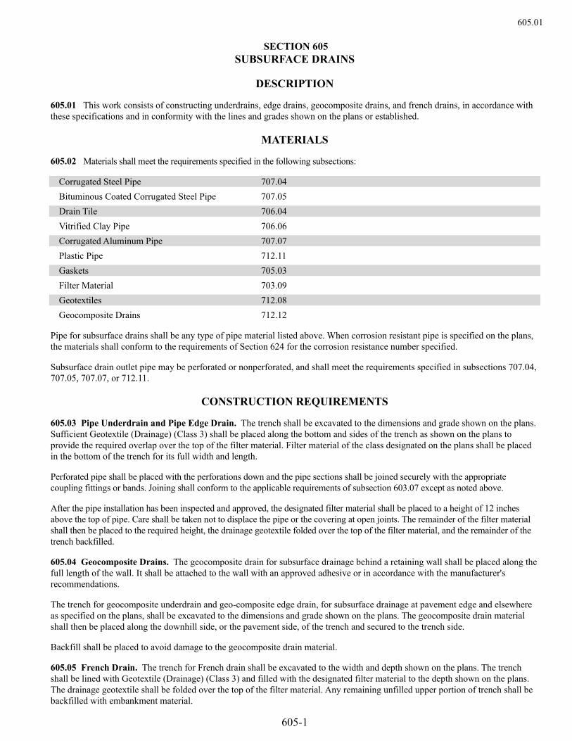
605.01
605-1
Section 605SECTION 605 SUBSURFACE DRAINS
DESCRIPTION
605.01 This work consists of constructing underdrains, edge drains, geocomposite drains, and french drains, in accordance with these specifications and in conformity with the lines and grades shown on the plans or established.
MATERIALS
605.02 Materials shall meet the requirements specified in the following subsections:
Corrugated Steel Pipe 707.04 Bituminous Coated Corrugated Steel Pipe 707.05 Drain Tile 706.04 Vitrified Clay Pipe 706.06 Corrugated Aluminum Pipe 707.07 Plastic Pipe 712.11 Gaskets 705.03 Filter Material 703.09 Geotextiles 712.08 Geocomposite Drains 712.12
Pipe for subsurface drains shall be any type of pipe material listed above. When corrosion resistant pipe is specified on the plans, the materials shall conform to the requirements of Section 624 for the corrosion resistance number specified.
Subsurface drain outlet pipe may be perforated or nonperforated, and shall meet the requirements specified in subsections 707.04, 707.05, 707.07, or 712.11.
CONSTRUCTION REQUIREMENTS
605.03 Pipe Underdrain and Pipe Edge Drain. The trench shall be excavated to the dimensions and grade shown on the plans. Sufficient Geotextile (Drainage) (Class 3) shall be placed along the bottom and sides of the trench as shown on the plans to provide the required overlap over the top of the filter material. Filter material of the class designated on the plans shall be placed in the bottom of the trench for its full width and length.
Perforated pipe shall be placed with the perforations down and the pipe sections shall be joined securely with the appropriate coupling fittings or bands. Joining shall conform to the applicable requirements of subsection 603.07 except as noted above.
After the pipe installation has been inspected and approved, the designated filter material shall be placed to a height of 12 inches above the top of pipe. Care shall be taken not to displace the pipe or the covering at open joints. The remainder of the filter material shall then be placed to the required height, the drainage geotextile folded over the top of the filter material, and the remainder of the trench backfilled.
605.04 Geocomposite Drains. The geocomposite drain for subsurface drainage behind a retaining wall shall be placed along the full length of the wall. It shall be attached to the wall with an approved adhesive or in accordance with the manufacturer's recommendations.
The trench for geocomposite underdrain and geo-composite edge drain, for subsurface drainage at pavement edge and elsewhere as specified on the plans, shall be excavated to the dimensions and grade shown on the plans. The geocomposite drain material shall then be placed along the downhill side, or the pavement side, of the trench and secured to the trench side.
Backfill shall be placed to avoid damage to the geocomposite drain material.
605.05 French Drain. The trench for French drain shall be excavated to the width and depth shown on the plans. The trench shall be lined with Geotextile (Drainage) (Class 3) and filled with the designated filter material to the depth shown on the plans. The drainage geotextile shall be folded over the top of the filter material. Any remaining unfilled upper portion of trench shall be backfilled with embankment material.

605-2
605.06 Subsurface Drain Outlet. The trench for subsurface drain outlet shall be excavated to the width and depth necessary to place the pipe on a drainable grade, as shown on the plans or as directed. Pipe shall be laid in the trench with all ends joined securely with the appropriate couplings, fittings or bands. After inspection and approval of the pipe installation, the trench shall be backfilled and compacted in accordance with subsection 206.03.
Where the outlet pipe ends on a slope or ditch, it shall be constructed with an erosion control pad, and an animal guard. The location shall be marked with a delineator post that conforms to Section 612. The animal guard screen shall be held securely in place with a coupling or fastening band or by another approved method.
METHOD OF MEASUREMENT
605.07 Pipe underdrain and pipe edge drain will be measured by the linear foot of pipe of the size specified placed and accepted. French drain will be measured by the linear foot of trench excavated and filled with filter material and accepted. Geocomposite underdrain and geocomposite edge drain will be measured by the linear foot along the base of the geocomposite drain material for the full length installed and accepted. Geocomposite drain both with and without pipe will be measured by, the square yard of geocomposite drain material placed on the vertical wall surface and accepted. Subsurface drain outlet will be measured by the linear foot of pipe placed and accepted from the end of a subsurface drain to the discharge end of the outlet pipe.
BASIS OF PAYMENT
605.08 The accepted quantities of subsurface drains will be paid for at the contract unit price for each of the pay items listed below that appear in the bid schedule.
Payment will be made under:
Pay Item Pay Unit ___Inch Perforated Pipe Underdrain Linear Foot French Drain Linear Foot Geocomposite Underdrain Linear Foot Geocomposite Drain without Pipe Square Yard Geocomposite Drain with Pipe Square Yard Geocomposite Edge Drain Linear Foot Pipe Edge Drain Linear Foot Subsurface Drain Outlet Linear Foot
Payment shall be full compensation for all work and materials required to complete the item including drainage geotextile, drainage core, securing devices, adhesives, sewn seams, pipe, filter material, excavation, and backfill. Payment for subsurface drain outlet shall include the erosion control pad, the animal guard, and the delineator post.

606.01
606-1
Section 606SECTION 606 GUARDRAIL
DESCRIPTION
606.01 This work consists of the construction of guardrail in accordance with these specifications and in conformity with the lines and grades shown on the plans or established.
The construction of the various types of guardrail shall include the assembly and erection of all component parts and materials complete at the locations shown on the plans or as directed.
The types of guardrail are designated as follows:
Type 3 Guardrail – Midwest Guardrail System (MGS) W-Beam 31 Inches Type 6 Guardrail – Thrie Beam Type 7 Guardrail – F-Shape Concrete Barrier (Precast) (Temporary) Type 9 Guardrail – Single Slope Concrete Barrier Use of Type 4 Precast Concrete Barrier not permitted.
MATERIALS
606.02 Materials shall meet the requirements specified in the following subsections:
“W” Beam Rail and Thrie Beam Rail 710.05 Guardrail Hardware 710.09 Guardrail Posts 710.08
Paint for field painting of guardrail shall conform to subsection 708.03, Structural Steel Bridge Paint.
Concrete for precast or cast-in-place barrier shall be made with an approved Class D Concrete and shall conform to the requirements of Section 601. The Contractor may elect to use an approved self-consolidating Class D concrete. Reinforcing steel, unless otherwise noted, shall be epoxy coated and conform to the requirements of Section 602. Concrete for bridge rail shall be an approved Macro Fiber-Reinforced Class D Concrete and conform to the requirements of Section 601.
CONSTRUCTION REQUIREMENTS
606.03 Post and Rail Elements.
(a) Posts. Posts shall be set firm and aligned with a tolerance of plus or minus 1/4 inch from plumb, grades and lines as staked. All fittings and metal plates shall be placed securely in position to conform to designated dimensions and requirements.
Posts shall be set by one of the following methods:
(1) Driven in place.
(2) Set in dug holes.
(3) Set in a concrete base.
(4) Posts on bridges shall be as shown on the plans.
Driving of posts shall be accomplished by methods and equipment that will leave the posts in their final position free from any distortion, burring, or any other damage.
Excavated post holes shall have a firm bottom and be backfilled with acceptable material placed in layers and thoroughly compacted.
Dissimilar metal-to-metal or aluminum-to-concrete post or rail installations shall have contact surfaces separated by an approved protective coating.

606-2
Wood posts cut in the field shall have the cut surfaces protected with two coats of an approved preservative. When the cut surface is above ground, the treating solution to be used shall be the same type as was used in the original treatment.
(b) Rail. Rail elements shall be erected in a manner resulting in a smooth, continuous installation. All bolts in the finished rail shall be drawn tight. Bolts shall be of sufficient length to extend beyond the nuts. Rail shall be shop bent for installations on horizontal curves having a radius of 150 feet or less.
(c) Temporary End Treatment. In construction zones not closed to traffic, installation of rail element shall closely follow the setting of posts to keep the number of posts without rail at a minimum. When necessary to minimize potential hazards, the Engineer will specify the direction in which the rail installation is to advance and the number of posts installed ahead of rail installation. At the end of the Contractor’s work day, the Contractor shall treat the ends of the installed guardrail as follows:
(1) If the end is at the location of a planned end section, install the end section.
(2) If the end is not at the location of a planned end section, the last rail section shall be installed with one end attached to the rail already in place and the free end resting on the ground. The free end on the ground shall be restrained by tying the rail to the posts by ropes or cables. The guardrail shall not be left in this configuration for more than 24 hours unless protected by an approved attenuating device.
606.04 Concrete. Where paving is removed or damaged due to the Contractor’s operations, the Contractor shall furnish an approved mix and shall repair the paving as required, at the Contractor’s expense.
In construction zones not closed to traffic, the Contractor shall treat the ends of the installed concrete guardrail at the end of the work day as follows:
(1) If the end is at the location of a planned end section, install the end section.
(2) If the end is not at the location of a planned end section, install a temporary impact attenuator or provide treatment as shown in the Contract.
(a) Permanent Concrete Barrier. The permanent concrete barrier shall be Type 9 constructed by cast-in-place or slipform methods. The trench for the base of the cast-in-place reinforced barrier end anchorages shall be excavated to the lines and grades shown on the plans or established. The bottom of the trench shall be compacted to the density specified in subsection 203.07(a). The compacted trench bottom shall be watered and approved before placing concrete.
Concrete finish for all cast-in-place barriers shall be Class 1 in accordance with subsection 601.14. Slipform barriers shall not receive additional finishing unless permitted by the Engineer. Exposed vertical surfaces of slipformed barrier shall receive a vertical broom finish. When hand finishing is allowed, it shall be performed in conformance with subsection 601.12(a).
The Engineer may determine that the exposed surfaces of the guardrail shall be tested with a 10-foot straightedge laid along the exposed surface in a longitudinal direction. The Contractor shall furnish an approved 10-foot straightedge and provide an operator to aid the Engineer in testing the exposed surfaces. All surface tolerances shall be measured in a longitudinal direction. Deviation of any exposed surface in excess of the tolerance specified shall be corrected at the Contractor’s expense.
Longitudinal surface tolerances for the top of the barrier and the sides of the barrier from the top to a line 7 inches below the top of the barrier are: (1) On tangent roadway alignments and curves with a radius greater than 1,000 feet: 0.25 inch from the edge of the
straightedge. (2) On sharp vertical curves and horizontal curves with a radius of 1,000 feet or less: 0.25 inch from the edge of the
straightedge with allowance made for curve deflection. Longitudinal surface tolerances for the remaining surfaces of the barrier are:
(1) On tangent roadway alignments and curves with a radius greater than 1,000 feet: 0.75 inch from the edge of the straightedge.
(2) On sharp vertical curves and horizontal curves with a radius of 1,000 feet or less: 0.75 inch from the edge of the straightedge with allowance made for curve deflection.

606.05
606-3
The Contractor will be allowed a maximum of three days of slipform production if the barrier being placed does not meet the specified tolerances. After the third day of placement of out-of-tolerance slipform barrier, the Contractor shall stop production. The Contractor shall submit a corrective action plan to the Engineer for review. The plan shall address corrective actions to the equipment and materials and a time frame for completion of the corrective actions. The plan shall address methods and materials to be used to correct out-of-tolerance barrier. Patching will not be allowed to correct out-of-tolerance barrier. Further placement of barrier will not be allowed until all previously placed barrier which failed to meet tolerances is corrected or removed. Each occurrence of out-of-tolerance slipform barrier shall be subject to the same corrective cycle.
(b) Temporary Precast Type 7 Concrete Barrier. Precast Type 7 Concrete Barrier (conforming to Standard Plan M-606-14) may be formed upside down to minimize air pockets and improve surface finish. Concrete finish for precast barriers shall be Class 1 in accordance with subsection 601.14. Each segment of the precast barrier shall not have spalls, corner breaks, and bottom spalls totaling more than 5 square feet of surface area which includes the base. All required hand finishing shall be performed in conformance with subsection 601.12(a).
Connecting loops shall not be frayed, stretched, or deformed. Gaps between units shall not exceed the dimensions shown on the plans. Precast barrier units shall not be lifted or stressed in any way before they have developed the strength of the concrete specified. Units shall be supported at designated pickup points. Connecting loops shall not be used as pickup points. Care shall be taken during fabrication, storage, handling, and transporting to prevent cracking, twisting, or other damage. Minor chips on edges may be patched with the approval of the Engineer. Breakage and chipping may be cause for rejection. Units damaged in such a way as to impair their appearance or suitability, in the opinion of the Engineer, shall be replaced at the Contractor’s expense. Units rejected by the Engineer shall be marked on both sides with an orange painted “R” approximately 12 inches high and 6 inches wide.
The base for placing precast barrier shall be prepared to the lines and grades shown on the plans or established. When it becomes necessary to connect cast-in-place barrier sections to precast barrier installations during construction, the cast-in-place sections shall be constructed complete with connecting hardware in accordance with Standard Plan M-606-14 to join the cast-in-place sections to the abutting precast sections. A fifteen-foot transition section shall be provided when attaching barriers of differing shapes.
METHOD OF MEASUREMENT
606.05 Guardrail will be measured by the linear foot along the centerline of the rail from end to end of completed and accepted rail as shown on the plans, excluding end anchorages, median terminals, and transitions.
End anchorages, median terminals, and transitions will be measured by the actual number placed and accepted. Each end anchorage, median terminal, or transition shall include all concrete, reinforcing steel, anchor bolts, cable, rods, turnbuckles, backing rail, plates, bolts, nuts, washers, and all other work and material necessary to complete the item.
Posts will be included in the quantities of guardrail of the specified type and not measured separately. Additional posts required for guardrail adjacent to bridges and obstructions, as shown on the plans, will not be measured and paid for separately but shall be included in the work.
BASIS OF PAYMENT
606.06 The accepted quantities of guardrail will be paid for at the contract unit price for the type specified.
Payment will be made under:
Pay Item Pay Unit Guardrail, Type___ Linear Foot End Anchorage, Type___ Each Guardrail, Type___ (____Post Spacing) Linear Foot Median Terminal Each End Anchorage (_____) Each Transition, Type _____ Each

606-4
All work and materials necessary and incidental to the temporary treatment of guardrail ends will not be measured and paid for separately but shall be included in the work.
Partial payments will not be made for partially completed guardrail runs that do not conform to the end treatments specified in subsections 606.03(c) or 606.04.
Polyolefin fiber reinforcement will not be measured and paid for separately, but shall be included in the work.
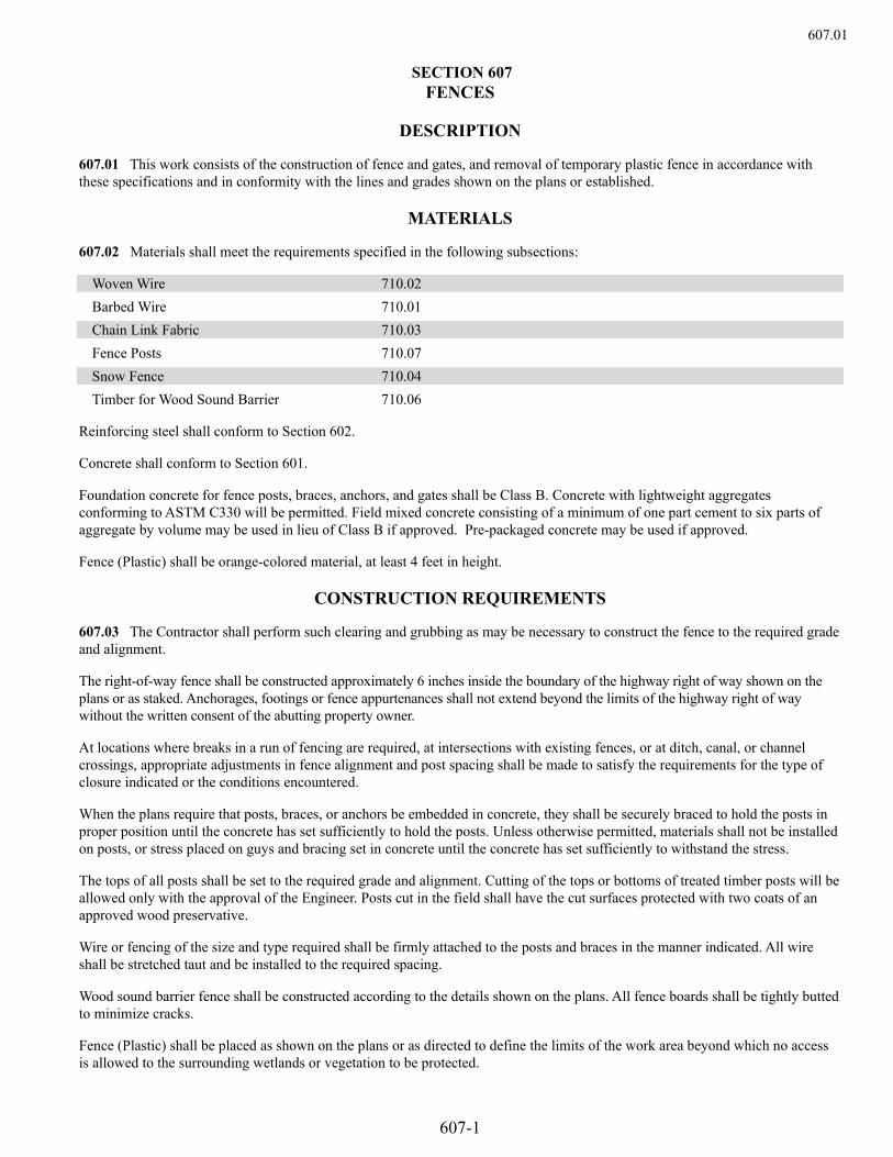
607.01
607-1
Section 607SECTION 607 FENCES
DESCRIPTION
607.01 This work consists of the construction of fence and gates, and removal of temporary plastic fence in accordance with these specifications and in conformity with the lines and grades shown on the plans or established.
MATERIALS
607.02 Materials shall meet the requirements specified in the following subsections:
Woven Wire 710.02 Barbed Wire 710.01 Chain Link Fabric 710.03 Fence Posts 710.07 Snow Fence 710.04 Timber for Wood Sound Barrier 710.06
Reinforcing steel shall conform to Section 602.
Concrete shall conform to Section 601.
Foundation concrete for fence posts, braces, anchors, and gates shall be Class B. Concrete with lightweight aggregates conforming to ASTM C330 will be permitted. Field mixed concrete consisting of a minimum of one part cement to six parts of aggregate by volume may be used in lieu of Class B if approved. Pre-packaged concrete may be used if approved.
Fence (Plastic) shall be orange-colored material, at least 4 feet in height.
CONSTRUCTION REQUIREMENTS
607.03 The Contractor shall perform such clearing and grubbing as may be necessary to construct the fence to the required grade and alignment.
The right-of-way fence shall be constructed approximately 6 inches inside the boundary of the highway right of way shown on the plans or as staked. Anchorages, footings or fence appurtenances shall not extend beyond the limits of the highway right of way without the written consent of the abutting property owner.
At locations where breaks in a run of fencing are required, at intersections with existing fences, or at ditch, canal, or channel crossings, appropriate adjustments in fence alignment and post spacing shall be made to satisfy the requirements for the type of closure indicated or the conditions encountered.
When the plans require that posts, braces, or anchors be embedded in concrete, they shall be securely braced to hold the posts in proper position until the concrete has set sufficiently to hold the posts. Unless otherwise permitted, materials shall not be installed on posts, or stress placed on guys and bracing set in concrete until the concrete has set sufficiently to withstand the stress.
The tops of all posts shall be set to the required grade and alignment. Cutting of the tops or bottoms of treated timber posts will be allowed only with the approval of the Engineer. Posts cut in the field shall have the cut surfaces protected with two coats of an approved wood preservative.
Wire or fencing of the size and type required shall be firmly attached to the posts and braces in the manner indicated. All wire shall be stretched taut and be installed to the required spacing.
Wood sound barrier fence shall be constructed according to the details shown on the plans. All fence boards shall be tightly butted to minimize cracks.
Fence (Plastic) shall be placed as shown on the plans or as directed to define the limits of the work area beyond which no access is allowed to the surrounding wetlands or vegetation to be protected.
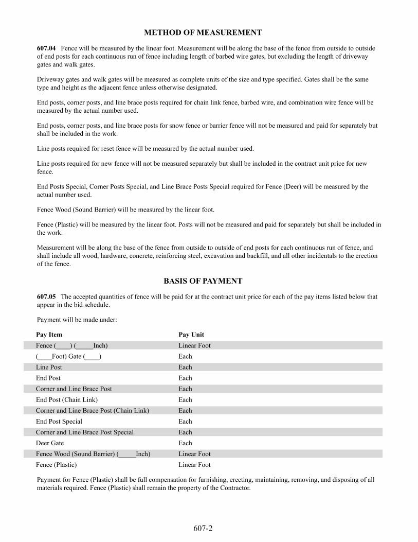
607-2
METHOD OF MEASUREMENT
607.04 Fence will be measured by the linear foot. Measurement will be along the base of the fence from outside to outside of end posts for each continuous run of fence including length of barbed wire gates, but excluding the length of driveway gates and walk gates.
Driveway gates and walk gates will be measured as complete units of the size and type specified. Gates shall be the same type and height as the adjacent fence unless otherwise designated.
End posts, corner posts, and line brace posts required for chain link fence, barbed wire, and combination wire fence will be measured by the actual number used.
End posts, corner posts, and line brace posts for snow fence or barrier fence will not be measured and paid for separately but shall be included in the work.
Line posts required for reset fence will be measured by the actual number used.
Line posts required for new fence will not be measured separately but shall be included in the contract unit price for new fence.
End Posts Special, Corner Posts Special, and Line Brace Posts Special required for Fence (Deer) will be measured by the actual number used.
Fence Wood (Sound Barrier) will be measured by the linear foot.
Fence (Plastic) will be measured by the linear foot. Posts will not be measured and paid for separately but shall be included in the work.
Measurement will be along the base of the fence from outside to outside of end posts for each continuous run of fence, and shall include all wood, hardware, concrete, reinforcing steel, excavation and backfill, and all other incidentals to the erection of the fence.
BASIS OF PAYMENT
607.05 The accepted quantities of fence will be paid for at the contract unit price for each of the pay items listed below that appear in the bid schedule.
Payment will be made under:
Pay Item Pay Unit Fence (____) (_____Inch) Linear Foot (____Foot) Gate (____) Each Line Post Each End Post Each Corner and Line Brace Post Each End Post (Chain Link) Each Corner and Line Brace Post (Chain Link) Each End Post Special Each Corner and Line Brace Post Special Each Deer Gate Each Fence Wood (Sound Barrier) (_____Inch) Linear Foot Fence (Plastic) Linear Foot
Payment for Fence (Plastic) shall be full compensation for furnishing, erecting, maintaining, removing, and disposing of all materials required. Fence (Plastic) shall remain the property of the Contractor.
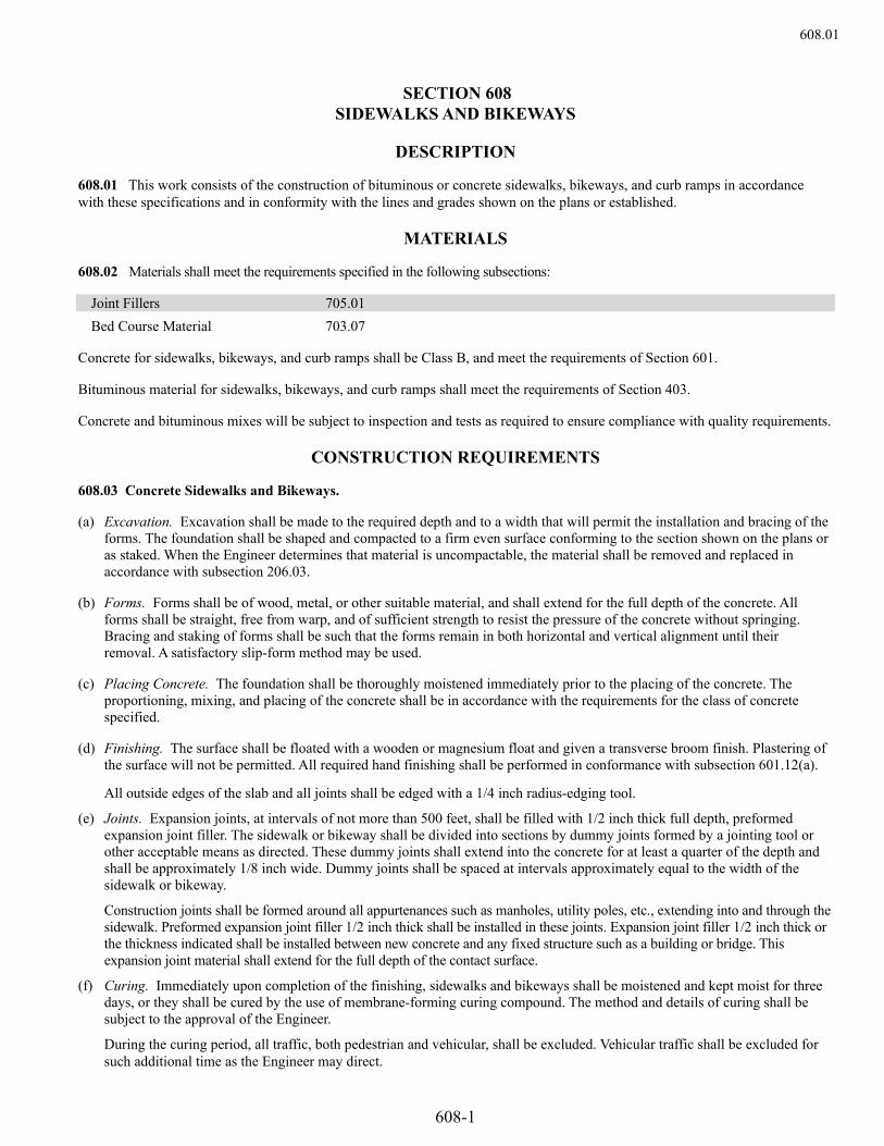
608.01
608-1
Section 608SECTION 608
SIDEWALKS AND BIKEWAYS
DESCRIPTION
608.01 This work consists of the construction of bituminous or concrete sidewalks, bikeways, and curb ramps in accordance with these specifications and in conformity with the lines and grades shown on the plans or established.
MATERIALS
608.02 Materials shall meet the requirements specified in the following subsections:
Joint Fillers 705.01 Bed Course Material 703.07
Concrete for sidewalks, bikeways, and curb ramps shall be Class B, and meet the requirements of Section 601.
Bituminous material for sidewalks, bikeways, and curb ramps shall meet the requirements of Section 403.
Concrete and bituminous mixes will be subject to inspection and tests as required to ensure compliance with quality requirements.
CONSTRUCTION REQUIREMENTS
608.03 Concrete Sidewalks and Bikeways.
(a) Excavation. Excavation shall be made to the required depth and to a width that will permit the installation and bracing of the forms. The foundation shall be shaped and compacted to a firm even surface conforming to the section shown on the plans or as staked. When the Engineer determines that material is uncompactable, the material shall be removed and replaced in accordance with subsection 206.03.
(b) Forms. Forms shall be of wood, metal, or other suitable material, and shall extend for the full depth of the concrete. All forms shall be straight, free from warp, and of sufficient strength to resist the pressure of the concrete without springing. Bracing and staking of forms shall be such that the forms remain in both horizontal and vertical alignment until their removal. A satisfactory slip-form method may be used.
(c) Placing Concrete. The foundation shall be thoroughly moistened immediately prior to the placing of the concrete. The proportioning, mixing, and placing of the concrete shall be in accordance with the requirements for the class of concrete specified.
(d) Finishing. The surface shall be floated with a wooden or magnesium float and given a transverse broom finish. Plastering of the surface will not be permitted. All required hand finishing shall be performed in conformance with subsection 601.12(a).
All outside edges of the slab and all joints shall be edged with a 1/4 inch radius-edging tool.
(e) Joints. Expansion joints, at intervals of not more than 500 feet, shall be filled with 1/2 inch thick full depth, preformed expansion joint filler. The sidewalk or bikeway shall be divided into sections by dummy joints formed by a jointing tool or other acceptable means as directed. These dummy joints shall extend into the concrete for at least a quarter of the depth and shall be approximately 1/8 inch wide. Dummy joints shall be spaced at intervals approximately equal to the width of the sidewalk or bikeway.
Construction joints shall be formed around all appurtenances such as manholes, utility poles, etc., extending into and through the sidewalk. Preformed expansion joint filler 1/2 inch thick shall be installed in these joints. Expansion joint filler 1/2 inch thick or the thickness indicated shall be installed between new concrete and any fixed structure such as a building or bridge. This expansion joint material shall extend for the full depth of the contact surface.
(f) Curing. Immediately upon completion of the finishing, sidewalks and bikeways shall be moistened and kept moist for three days, or they shall be cured by the use of membrane-forming curing compound. The method and details of curing shall be subject to the approval of the Engineer.
During the curing period, all traffic, both pedestrian and vehicular, shall be excluded. Vehicular traffic shall be excluded for such additional time as the Engineer may direct.

608-2
608.04 Bituminous Sidewalks and Bikeways.
(a) Excavation and Forms. Excavation and forms shall meet the requirements of subsection 608.03(a) and (b).
(b) Bed Course. Bed course material shall be placed in layers not exceeding 4 inches in depth and each layer shall be thoroughly compacted.
(c) Placing Bituminous Material. Bituminous sidewalk and bikeway material shall be placed on the compacted bed course in one or more courses as indicated to give the required depth when rolled. When practicable, spreading, finishing, and compaction shall be accomplished by equipment conforming to the requirements of Section 401. When the Engineer determines such equipment is not practicable, bituminous material may be spread by small or special pavers, by spreader boxes, or by blade graders and may be compacted by small self-propelled rollers or vibratory compactors acceptable to the Engineer. In areas inaccessible to the roller, hand or mechanical tamping will be permitted. Bituminous material shall be uniformly compacted.
The Contractor shall state at the Pre-construction Conference what type of paving equipment will be used.
METHOD OF MEASUREMENT
608.05 Concrete sidewalks, bikeways, and curb ramps will be measured by the square yard of finished surface. Bituminous sidewalks, bikeways, and curb ramps will be measured by the ton of bituminous mixture placed.
BASIS OF PAYMENT
608.06 The accepted quantities will be paid for at the contract unit price for each of the pay items listed below that appear in the bid schedule.
Payment will be made under:
Pay Item Pay Unit Concrete Sidewalk Square Yard Bituminous Sidewalk Ton Concrete Curb Ramp Square Yard Bituminous Curb Ramp Ton Concrete Bikeway Square Yard Bituminous Bikeway Ton
Bed course material will be measured and paid for in accordance with Section 206.
All work necessary and incidental to the construction of sidewalks, bikeways, and curb ramps will not be measured and paid for separately but shall be included in the work.

609.01
609-1
Section 609SECTION 609 CURB AND GUTTER
DESCRIPTION
609.01 This work consists of the construction of curb, gutter or combination curb and gutter in accordance with these specifications and in conformity with the lines and grades shown on the plans or established.
The types of curb are designated as follows:
Type 2 Cast-in-Place Concrete Curb Type 4 Dowelled Concrete Curb Type 6 Sloping Curb
The section will be as shown on the plans.
MATERIALS
609.02 Except as provided below the materials used shall meet the requirements of the following subsections:
Bed Course Material 703.07 Joint Filler 705.01 Reinforcing Steel 709.01
Concrete for curb shall be Class B, and meet the requirements of Section 601.
Bituminous curb shall be constructed of the same gradation of aggregate and the same grade of bituminous material as the top layer or top course of bituminous pavement used on the project.
Concrete and bituminous mixes will be subject to inspection and tests at the plants for compliance with quality requirements.
CONSTRUCTION REQUIREMENTS
609.03 Cast-in-Place Concrete Curb. All required hand finishing shall be performed in conformance with subsection 601.12(a).
(a) Excavation. Excavation and bedding shall conform to the requirements of subsection 608.03(a).
(b) Forms. Forms shall be of wood or metal, straight, free from warp and of such construction that there will be no interference to the inspection of grade or alignment. All forms shall extend for the entire depth of the curb and shall be braced and secured sufficiently so that no deflection from alignment or grade will occur during the placing of the concrete.
(c) Mixing and Placing. Concrete shall be proportioned, mixed, and placed in accordance with the requirements for the class of concrete specified. Compaction of concrete curb, gutters, or combination curb and gutter, placed in forms shall have thorough consolidation that shall be achieved by tamping and spading, vibrating, or other acceptable methods. Forms shall be left in place until the concrete has set sufficiently so that they can be removed without injury to the curb. Upon removal of the forms, the exposed curb face shall be immediately finished to a uniform surface. For the purpose of matching adjacent concrete finishes or for other reasons, the Engineer shall approve methods of finishing. Plastering will not be permitted.
(d) Sections. Curb shall be constructed in sections having a uniform length of 10 feet unless otherwise ordered. Sections shall be separated by open joints 1/8 inch wide except at expansion joints.
(e) Expansion Joints. Expansion joints shall be formed at the intervals shown on the plans using a 1/2 inch preformed expansion joint filler. When the curb is constructed adjacent to or on concrete pavement, expansion joints shall be located opposite the expansion joints in the pavement.
Expansion joints shall be installed between the concrete curb and any fixed structure or bridge. Expansion joint material shall extend the full depth of contact surface.
(f) Curing. Immediately upon completion of the finishing, the curb shall be moistened and kept moist for three days, or the curb shall be cured by the use of membrane-forming curing compound. The method and details of curing shall be subject to the approval of the Engineer.
609-2
(g) Backfilling. After the concrete has set sufficiently, the spaces in back of the curb shall be backfilled to the required elevation with suitable material, which shall be thoroughly tamped.
(h) Curb Machine. With the approval of the Engineer, the curb may be constructed by the use of a curb-forming machine. (i) Surface Tolerance. The Engineer may determine that the exposed surfaces of the concrete curb, gutters, or combination
curb and gutter shall be tested with a 10-foot straightedge laid along the exposed surface in a longitudinal direction. The Contractor shall furnish an approved 10-foot straightedge and provide an operator to aid the Engineer in testing the exposed surfaces. All surfaces shall be measured in a longitudinal direction. Deviation of any exposed surface in excess of that specified shall be corrected at the Contractor’s expense. Longitudinal surface tolerances for the top and face are: (1) On tangent roadway alignments and curves with a radius greater than 1,000 feet: 0.25 inch from the edge of the
straightedge. (2) On sharp vertical curves and horizontal curves with a radius of 1,000 feet or less: 0.25 inch from the edge of the
straight edge with allowance made for curve deflection. 609.04 (unused)
609.05 Bituminous Curb.
(a) Preparation. Bituminous curb shall be placed on a clean dry surface. Immediately prior to placing the bituminous mixture, the surface shall receive a tack coat of bituminous material of the type and grade approved by the Engineer. The rate of application of the tack coat material shall be 0.05 to 0.15 gallons per square yard of surface. In the application of this tack coat, the Contractor shall prevent the spread of this tack coat to areas outside of the area to be occupied by the curb.
(b) Placing. Bituminous curb shall be constructed by using a self-propelled curb machine or a paver with curb attachments.
The automatic curb machine shall meet the following requirements and shall be approved prior to its use:
(1) The weight of the machine shall be such that compaction is obtained without the machine riding above the bed on which the curb is constructed.
(2) The machine shall form curb that is uniform in texture, shap,e and density.
(3) The Engineer may permit the construction of curb by other means, when short sections or sections with short radii are required, or for such other reasons as warranted. The resulting curb shall conform in all respects to the curb produced by the use of the machine.
Upon completion of placement of bituminous curb, a fog coat of emulsified asphalt shall be placed on the exposed surfaces of the curb at the rate of approximately 0.1 gallon per square yard.
(c) Painting and Sealing. When sealing or painting is required, it shall be performed only on a curb that is clean and dry and which has reached the ambient temperature.
METHOD OF MEASUREMENT
609.06 Curb will be measured by linear foot along the front face of the section at the finished grade elevation. Gutter will be measured along the centerline of the gutter. Curb and gutter will be measured along the face of the curb. Deduction in length will be made for drainage structures, such as catch basins, drop inlets, etc., installed in the curb, gutter, or curb and gutter.
BASIS OF PAYMENT
609.07 The accepted quantities will be paid for at the contract unit price for each of the pay items listed below that appear in the bid schedule, including dowels and expansion joint material.
Payment will be made under:
Pay Item Pay Unit Curb, Type__ (Section____) Linear Foot Gutter, Type__ (____Foot) Linear Foot Curb and Gutter, Type__ (Section____) Linear Foot
Bed course material will be measured and paid for in accordance with Section 206.
Fog coat and tack coat for Curb Type 6 will not be measured and paid for separately but shall be included in the work.

610.01
610-1
Section 610SECTION 610 MEDIAN COVER MATERIAL
DESCRIPTION
610.01 This work consists of the construction of median cover over the median area, or over other areas designated, in accordance with these specifications and in conformity with the lines and grades shown on the plans or established.
MATERIALS 610.02 Bituminous median cover material shall conform to the requirements of Section 403 and as shown on the plans.
Concrete shall be Class B and shall conform to Section 601. Coloring agent, if required, shall be as shown on the plans or specified.
Aggregate for median cover shall conform to the requirements of subsection 703.10.
Plastic sheeting shall be black polyethylene with a minimum thickness of 10 mils or approved equal.
Herbicides shall conform to the requirements of Section 217.
CONSTRUCTION REQUIREMENTS 610.03 Median cover operations shall not be started until the underlying surface has been compacted, smoothed and, if required, treated with herbicides. Other requirements are as follows:
(a) Bituminous Median Cover Material. Bituminous median cover material shall be placed in conformance with the requirements of subsection 608.04(c).
(b) Concrete. Construction requirements shall conform to the requirements of subsection 608.03. The surface finish or pattern shall be as shown on the plans or in accordance with the recommendations of the supplier of the median cover material.
(c) Stone. Areas to receive stone median cover shall be treated, if required, with an approved herbicide treatment in accordance with Section 217 or as directed. Immediately after the placement of the herbicides, the plastic sheeting and stones shall be placed in accordance with details shown on the plans, or as specified.
METHOD OF MEASUREMENT 610.04 Bituminous median cover material will be measured by the number of tons of bituminous material placed and accepted.
Concrete median cover material will be measured by the square foot of surface placed and accepted.
Stone median cover material will be measured by the number of tons of aggregate placed and accepted.
BASIS OF PAYMENT
610.05 The accepted quantities will be paid for at the contract unit price for each of the pay items listed below that appear in the bid schedule.
Payment will be made under:
Pay Item Pay Unit Median Cover Material (Bituminous) Ton Median Cover Material (Concrete) Square Foot Median Cover Material (Patterned Concrete) Square Foot Median Cover Material (Stone) Ton
Herbicide treatment will be measured and paid for in accordance with Section 217.
Subgrade compaction and plastic sheeting will not be measured and paid for separately but shall be included in the work.

610-2
THIS PAGE INTENTIONALLY LEFT BLANK

611.01
611-1
Section 611SECTION 611 CATTLE GUARDS
DESCRIPTION
611.01 This work consists of the construction of cattle guards in accordance with these specifications and in conformity with the lines, grades, and details shown on the plans or established.
MATERIALS 611.02 Concrete shall conform to the requirements of Section 601. Reinforcing steel shall conform to the requirements of Section 602. Structural steel shall conform to the requirements of Section 509. Timber shall conform to the requirements of Section 508. Fencing items shall conform to the requirements of Section 607.
CONSTRUCTION REQUIREMENTS 611.03 Cattle guards shall be constructed in accordance with the details shown on the plans. All work shall be done in accordance with the applicable construction methods contained in these specifications.
METHOD OF MEASUREMENT 611.04 Cattle guards will be measured by the number of units of the various sizes installed and accepted.
BASIS OF PAYMENT
611.05 The accepted quantities of cattle guards of the various sizes will be paid for at the contract unit price each when included in the bid schedule.
Payment will be made under:
Pay Item Pay Unit _____Cattle Guard Each

611-2
THIS PAGE INTENTIONALLY LEFT BLANK

612.01
612-1
ECTIOSECTION 612
Section 612DELINEATORS AND REFLECTORS
DESCRIPTION
612.01 This work consists of the installation and furnishing of delineators and reflectors in accordance with these specifications and in conformity with the lines, grades and details shown on the plans or established.
MATERIALS
612.02 Materials for the various types of delineators and reflectors shall be as follows:
(a) Delineators.
1. Steel Posts. Details for each type of delineator are shown on the plans. Posts shall conform to the requirements shown on the plans, and reflectors shall conform to the requirements in subsections 713.07 and 713.10.
2. Flexible Posts. Flexible posts shall be manufactured from an impact resistant flexible material and shall conform to the following requirements: A. Workmanship. The posts shall exhibit good workmanship and shall be free of burrs, discoloration, contamination,
and other objectionable marks or defects, which affect appearance or serviceability.
B. Base Anchoring. The posts shall be designed to facilitate a permanent installation that resists overturning, twisting, and displacement from wind and impact forces. It shall have an anchoring depth of 22 1/2 to 23 inches per CDOT Standard Plan S-612-1 or manufacturer’s recommendation. A concrete foundation shall be used for delineator support in soft soils per the plans or as directed by the Engineer.
The posts or below-ground anchors shall be capable of being driven into an earth shoulder or roadside with or without a pilot hole. Installation shall be accomplished with typical maintenance equipment.
C. Reflective Elements. Posts shall be shaped to accommodate the installation of reflective elements. Reflective
elements shall be 3 inches square for Type I, 3 inches by 6 inches for Type II, and 3 inches by 9 inches for Type III (hazard marker) delineators. Reflective material shall be Type IV reflective sheeting meeting the requirements of subsection 713.10. The top of the reflective element shall be mounted no more than 2 inches from the top of the post, with the reflective element facing in the direction of the oncoming traffic. The reflective element shall be mounted in accordance with the manufacturer's recommendations to prevent loss of the reflective element during the life of the post. The reflective element shall be protected from scratches, abrasions, and other physical damage during shipping and driving by an easily removable "masking" sheet.
D. Marking. The tops of the posts on the side away from traffic shall be date-stamped showing the month and year of
fabrication. The numerals shall be at least 1/4 inch in height and shall be either die-stamped, or legibly stamped with permanent ink. In addition, each post shall be marked with a black horizontal stripe to denote an 18-inch embedment depth.
E. Dimensions.
(1) Width. The post shall have a minimum width of 2 3/8 inches and a maximum width of 4 1/8 inches facing traffic with a 0.22-inch minimum wall thickness.
(2) Length. The post shall be of such length to provide a height of 48 inches above the edge of the pavement and to provide the required anchoring depth for the Drivable Method of installation. The post length shall adhere to the requirements outlined in S-612-1 for all other installation methods.
F. Physical Properties and Performance Requirements. Flexible posts shall conform to the following physical
properties and performance requirements.

612-2
(1) Heat Resistance: The post shall be conditioned a minimum of two hours in an oven at 140 °F plus or minus 3 °F. The conditioned post shall be capable of straightening itself within five minutes when bent 90 degrees at the midpoint for each of four bends. The conditioning temperature shall be maintained while the test on each post is completed.
(2) Cold Resistance: The post shall be conditioned a minimum of two hours at -5 °F plus or minus 3 °F in an
environmentally controlled test chamber. Testing shall be performed in the environmental chamber.
(i) The post shall not be adversely affected when a person, standing approximately at the center of the post, bends the free half of the post to a 90-degree angle with the remaining section being stood upon. The post shall return to its original shape within 60 seconds for each of four separate bends.
(ii) A steel ball weighing 2 pounds shall be dropped a distance of 5 feet through a virtually frictionless vertical guide to impact the surface of the post. The surface of the post being struck by the steel ball shall be in a horizontal position, with the post supported and held in position at both ends. The post shall be subjected to five impact tests concentrated near the middle of the post. Fracturing, cracking, or splitting of the post shall constitute failure.
(3) Colorfastness: Post shall be exposed for 500 hours in a Carbon-Arc Type weatherometer (ASTM G23,
Method 1). The post shall show no signs of delamination, distress, or discoloration, and the reflective sheeting shall not be removable from the post without damage.
(4) Impact Resistance: The post shall be manufactured from an impact resistant material and be so designed that an installed post is capable of self-erecting and remaining serviceable after being subjected to a series of direct impacts by a typical passenger sedan at temperatures of 40 °F or above. The posts to be tested shall be installed in accordance with the recommendations of the manufacturer. The posts shall be furnished complete with attached reflectors proposed for use. Posts shall be capable of withstanding a series of ten impacts head on (90 degrees) into traffic face of the post at a speed of 35 mph. Posts shall also be capable of withstanding a series of five impacts at an angle of 75 degrees to the traffic face of the post at speeds of 55 mph. The impacting vehicle shall suffer little or no damage during the impact test series. After each impact, the post shall:
(i) Remain intact and securely anchored.
(ii) Return to its original vertical orientation within an angle of 10 degrees from vertical.
(iii) Show minimal signs of distress (cracking, loss of rigidity).
(iv) Retain a minimum of 50 percent of its original amount of reflective sheeting.
(5) Each post, prior to and after installation, shall be visibly free of bends or twists. (6) The posts shall have a minimum tensile strength of 1,100 pounds per square inch, as determined in
accordance with ASTM D 638. (7) The color of the posts shall be Interstate Green in accordance with Federal Standard No. 595B, Color No.
14109, unless otherwise specified. (8) The post (excluding post, clamp and cup mount types) shall have a simple non-mechanical flexible joint.
The flexible joint shall have a square to round configuration that transitions from the ground anchor to the post and shall enable the posts to self-right after omni-directional impacts. The square end shall be molded to exactly fit inside the 2-inch square tubing opening and transitions to a round configuration to exactly fit inside the delineator post. The flexible joint shall be fully inserted in both ends to allow proper installation of securing hardware and self-righting properties.

612.03
612-3
(9) The post shall be permanently sealed at the top and have a 13 inch flattened surface to accommodate up to three (3-inch by 3-inch) reflective sheets. A Type I delineator shall have one (3-inch by 3-inch) reflective sheet on one side, a Type II shall have two (3-inch by 3-inch) reflective sheets on one side and a Type III shall have three (3-inch by 3-inch) reflective sheets on one side. Reflective sheets shall be placed in a straight vertical column starting one inch from the top edge of the delineator. Type II and III delineators shall have reflective sheets separated by one inch vertically in the column. All reflective sheets shall be placed at the factory by the fabricator prior to on-site delivery of delineators. The texture of the projected surface shall be smooth and suitable for the adherence of reflective sheeting without preparation other than wiping with a clean cloth damped with mineral spirits to remove oil-type contaminants.
(10) The post shall be comprised of high density thermoplastic, consisting of a minimum of 70 percent by volume,
post-consumer recycled HDPE, with an interstate green, premium U.V. inhibited, co-extruded HDTP shell and a flexible insert which transitions from square to round.
(11) The anchor shall be galvanized steel perforated tubing.
G. Sampling and Acceptance. Prior to shipment of the posts, the manufacturer shall submit certified test reports and
test data, developed by an approved testing laboratory which attests to the fact that their marker post complies in all respects with requirements covered in the specifications.
3. Reflector Strip. Reflector strip shall be 3M “Scotchlite” Series 344/346.
(b) Median Barrier Reflector. Details for the median barrier reflector are shown on the plans. Reflectivity shall conform to the requirements in subsection 713.10.
CONSTRUCTION REQUIREMENTS
612.03 Spacing, location, color of reflectors and placement of delineator posts shall be as shown on the plans.
The Contractor shall install reflector strips in conformance with manufacturer’s recommendations.
The length of each reflector strip shall be 34 inches, unless otherwise approved. The Contractor shall adjust the spacing between reflector strips as recommended by the manufacturer to fit the location called for in the Contract. Cutting of the reflector strips will not be permitted.
METHOD OF MEASUREMENT
612.04 Delineators and reflectors for median barrier will be measured by the actual number of the various types installed and accepted.
BASIS OF PAYMENT
612.05 The accepted quantities will be paid for at the contract unit price each for the pay items listed below that are included in the bid schedule.
Payment will be made under:
Pay Item Pay Unit Delineator (Type______) Each Delineator (Flexible) (Post Mounted) Each Delineator (Flexible) (Clamp Mounted) Each Delineator (Flexible) (Cup Mounted) Each Delineator (Flexible) (Surface Mounted) Each Delineator (Flexible) (Type___) Each Delineator (Drivable) (Type___) Each Reflector (Median Barrier) Each Reflector Strip (__ Inch) Each
Concrete for anchor embedment will not be measured and paid for separately, but shall be included in the work.

612-4
Surface preparation, brackets, fasteners and adhesive for reflector strips will not be measured and paid for separately, but shall be included in the work.
Payment will be full compensation for all work, materials, and equipment required to install delineators.

613.01
613-1
Section 613SECTION 613 LIGHTING
DESCRIPTION
613.01 This work consists of furnishing and installing foundations, light standards, luminaires, light sources, conduit, cable, wiring, and incidental materials for highway lighting and electrical systems in accordance with these specifications and in conformance with the details, lines, grades, and locations shown on the plans or established.
MATERIALS
613.02 Roadway lighting materials shall conform to Section 715 and shall be compatible with the requirements of the local agency having jurisdiction. (a) Foundation. Concrete Foundation Pads and Light Standard Foundations shall be cast-in-place concrete. A complete
foundation includes the concrete, reinforcing steel, grounding electrode, connector bolts, and anchor bolts. Connector bolts and anchor bolts shall accommodate the anchorage of the light pole from its base flange to the base or transformer base, and from the base or transformer base to the light standard foundation.
(b) Light Standard. A complete light standard includes the metal light pole, mast arm or arms, base or transformer base, approved breakaway device (optional), in-use receptacles (optional), grounding system, and all hardware. When a transformer base is not used, the pole shall have a handhole.
(c) Conduit. Conduit includes all junction boxes, pull wire, weatherheads, adaptors, and expansion joints for conduit required to
install complete runs.
(d) Electrical Warning Tape. Electrical warning tape shall consist of pre-manufactured non-adhesive polyethylene material that is unaffected by acids, alkalis, and other soil components. The tape shall be detectable. The color of the tape shall be red, and it shall be a minimum 3.5 mils thick and 6 inches wide. Its tensile strength shall be 1,750 psi lengthwise.
The electrical tape shall include the following identification printed in black letters continuously along the length of the tape: “CAUTION BURIED ELECTRIC LINE BELOW”. The identification note and color of tape shall conform to the requirements of the “American Public Works Association (APWA) Uniform Color Codes (Red) – Electrical Power Lines, Cables, Conduit and Lighting Cables”.
(e) Luminaire. A complete luminaire includes the housing, lens, Light Emitting Diode (LED) board, dimming driver, slip-fitting clamp or approved manufacturer mounting, all necessary internal wiring, and 7-pin photoelectric control receptacle. Luminaires shall operate at either 120 VAC (Volts Alternating Current), 60 Hz, 277 VAC, 60 Hz. or 120-277VAC, 60 Hz.
(f) Lighting Control Center. A complete lighting control center includes the load center, grounding system, contactors, relays, meter housing (optional per region requirements), meter disconnect (optional per region and utility company requirements), maintenance receptacle, photoelectric control, NEMA 4 enclosure, HVAC (optional per region requirements), snow skirt (optional per region requirements) and all related components, and connections to the power supply.
(g) Meter Power Pedestal. A complete pedestal includes the NEMA 3R enclosure and all related components, load center,
grounding system, meter housing, meter disconnect (optional per utility company requirements) maintenance receptacle (optional), photoelectric control, and connections to the power supply.
(h) Secondary Service Pedestal. A complete pedestal includes the NEMA 3R enclosure and all related components and
connections to the power supply.
(i) Heavy Duty Safety Switch. Provide switches, mounted on the cabinet, with the following ratings:
(1) 30 to 1200 amperes. (2) 250 volts AC; 600 volts AC.
(3) 2, 3, 4 and 6 poles (2, 3 and 4 poles on 800 A; 2 and 3 on 1200 A).

613-2
(4) Fusible and non-fusible. (5) Mechanical lugs suitable for copper conductors.
(j) Wiring. Complete wiring includes control wiring, luminaire wiring, traffic signal wiring, main circuit wiring, ground
wiring, service entrance wiring, and all other wiring necessary for a complete installation.
(k) Materials List. At the Pre-Construction Conference, the Contractor shall submit to the Engineer three copies of a list of all materials and equipment to be incorporated into the work. The Contractor shall include the following items on the list:
(1) Light standard foundations. (2) Foundation pads. (3) Light standard type (steel or aluminum). (4) Luminaire manufacturer’s product information including data in Illuminating Engineering Society (IES) format, IES
photometric distribution type for vertical and lateral distribution and IES TM-15-11 rating (example: B2-U0-G1, Type III), and a photograph or line drawing.
(5) Luminaire mounting hardware. (6) Luminaire initial lumen output. (7) LED dimming driver or power supply. (8) Lighting control center(s) and photoelectric control device(s). (9) Secondary service pedestals. (10) All other items required for a complete installation.
The Engineer will return lists that are incomplete or that include unacceptable materials to the Contractor for correction and re-submission. The Contractor shall not order materials or equipment until the Engineer and the party or agency responsible for maintenance have reviewed and approved the materials and equipment list. The Engineer’s approval of the list shall not relieve the Contractor of responsibility for the proper functioning of the completed installation.
(l) LED Luminaire Warranty. The Contractor shall ensure that the LED luminaire has a manufacturer’s minimum warranty
of 10 years for all parts, materials, and shipping required to repair or replace the luminaire. The Contractor shall provide the manufacturer’s warranty to the Engineer prior to installing the luminaire.
The warranty shall cover all failures including:
(1) Failure in luminaire housing, wiring, connections, drivers, and photoelectric control devices. (2) More than 10 percent decrease in lumen output. (3) Significant change in color.
The warranty shall begin upon the date the Contractor receives the luminaire. The bill of lading shall be provided to the Engineer prior to final payment of the lighting.
(m) Technical Support. During the manufacturer’s warranty period, technical support shall be available from the
manufacturer via telephone within 24 hours of the time the call is made from the Contractor, and this support shall be made available from factory certified personnel or factory certified installers at no additional charge to the Department.
(n) Temporary Lighting. A complete temporary lighting system includes the temporary light standard, luminaire, mast arm, conduit, wiring, power source, temporary metering per the local utility standards, and all related components and connections to the power source.
613.03
613-3
CONSTRUCTION REQUIREMENTS
613.03 General. All work shall conform to these specifications and the National Electric Code (NEC) and shall comply with applicable regulations as specified in subsection 107.01. Each system shall be installed as designated. The Contractor shall furnish and install all incidentals necessary to provide a complete working unit or system.
613.04 Concrete Foundation Pads and Light Standard Foundations. Foundations shall be installed complete with grounding electrodes. Concrete Class D shall be used for foundation pads and concrete Class BZ shall be used for the light standard foundation. Concrete Class D can be used for light standard foundation if the rebar spacing in the foundation is at least 3 inches and the slump of the concrete is 6 to 9 inches. All concrete shall meet the requirements of Section 601. The drilled shaft (caisson) of the light standard foundation shall meet the requirements of Section 503. The Contractor shall test and report soil conditions to the Engineer if any of the following soil conditions are encountered during roadway work: (1) Light standards are not installed within the roadway earthwork prism. (2) The soil has a high organic content or consists of saturated silt and clay. (3) The site will not support the weight of the drilling rig. (4) The foundation soils are not homogenous. (5) Firm bedrock is encountered.
Between drilling of the shaft and placing of concrete the hole shall not be disturbed. Wet or caving holes shall be backfilled with flow-fill and re-drilled after a three-day curing period without the use of casing. If testing is required, then soil testing shall be performed at the lowest elevation light standard location for all light connected to a single electrical circuit. Foundations shall be installed at the final grade. All anchor bolts shall be positioned by means of steel templates. The center of the template shall coincide with the center of the base. Conduits shall be properly positioned and anchored before the concrete is placed. All foundations shall have ground electrodes conforming to the NEC. All foundations on structures shall be bonded to the structure steel by a method that is in accordance with the NEC and which is approved by the Engineer.
613.05 Light Standards. Poles shall be set plumb on the light standard foundation using non-corrosive metal shims or upper and lower nuts. Poles shall be level and plumb to the foundation. Defects and scratches on galvanized poles shall be given two coats of acceptable zinc-rich paint as directed. Defects and scratches on painted poles shall be primed and painted to match undamaged pole sections.
613.06 Luminaires, Light Sources, and Lamps. Roadway luminaires shall be mounted on the mast arm by a slip-fitter clamp or other approved device. Luminaires shall be adjusted vertically and horizontally to be plumb with the foundation and provide the required orientation and maximum light distribution on the roadway and meet IES TM-15 uplight rating of U0 (no uplight). Luminaires are to be controlled by a centralized photoelectric control. For modified systems, individual photoelectric control may be used. The photoelectric control shall be positioned northward to minimize sun interference. Luminaires of the specified type and initial lumen output shall be installed as specified. The type and initial lumen output shall be marked on each luminaire or pole in accordance with American National Standards Institute (ANSI) specifications. ANSI approved tags shall be provided and installed by the Contractor. Wall type luminaires for use under overpass structures shall be mounted as specified. All wall type luminaires shall include side shielding to prevent glare in the motorist’s view. The beam angle setting shall be adjusted to meet the project illumination requirements. After installation and prior to acceptance, refractors and lenses shall be cleaned to provide maximum lumen output.

613-4
613.07 Conduit. The electrical conduit system shall be installed in accordance with subsection 715.07 Conduit and CDOT’s “A Policy on the Accommodation of Utilities on Colorado Highways Rights-of-Way” and the following:
In the conduit system the locations of conduit, pull boxes, splice boxes and expansion joints shown on the plans are approximate. Actual locations shall be established during construction. The conduit system shall be located to avoid interference with known present or known future construction installations. All underground conduit runs and conduit risers on poles shall be installed as required for a complete installation. All conduit installed under the roadway shall be at least 2-inch inside diameter unless otherwise designated. The Contractor may use larger conduit than specified at no additional cost to the project. If larger conduit is used, it shall be for the entire run from outlet to outlet. Reducer couplings shall not be used. Existing underground conduit to be incorporated into a new system shall be cleaned with a round wire brush the same size as the internal diameter of the conduit, proofed with a mandrel ¼-inch less in diameter than the conduit inner diameter size, and blown out with compressed air. Where new conductors are to be added to existing conductors in a conduit, all conductors shall be removed and the conduit cleaned as described above. All conductors shall be pulled into the conduit as a unit. Conduit terminating in standards or pedestals shall extend approximately 2 inches vertically above the foundations and shall slope toward the handhole opening. Conduit entering pull boxes shall terminate 2 inches inside the box wall and no more than 1.5 inches above the bottom and shall slope toward the top of the box to facilitate pulling of conductors. Conduit entering through the bottom of a pull box shall be located near the end walls to leave the major portion of the box clear. All conduits shall be labeled as to the direction of their run. The ends of all conduits, whether shop or field cut, shall be reamed to remove burrs and rough edges. Cuts shall be made square and true so that the ends will butt or come together for their full circumference. Slip joints or running threads shall not be used for coupling conduit. When a standard coupling cannot be used for coupling metal type conduit, an approved threaded union coupling shall be used. All threads on ferrous metal conduit, not previously treated with a corrosion preventative, shall be painted with rust preventive paint before couplings are connected. All couplings for metal type conduit shall be tightened providing a continuous connection throughout the entire length of the conduit run to increase raceway mechanical strength. Areas where the coating on ferrous metal conduit has been damaged shall be painted with rust preventive paint. All metal conduit ends shall be threaded and capped until wiring is started. When caps are removed, the threaded ends shall be provided with conduit bushings. Non-metallic conduit shall be cut with a hacksaw or other approved tool. Non-metallic conduit connections shall be solvent-weld type or approved equal. Non-metallic conduit ends shall be capped until wiring is started. All conduit stub-outs shall include a sweeping elbow and shall terminate in the box. All conduit stub-outs shall be capped. Surface conduit connections at junction or splice boxes shall be tightly secured and waterproofed. All conduit ends shall be sealed with duct seal after installation of wiring. The duct seal shall be rated for outdoor use and easily removable. When specified, conduit shall be installed under existing pavement by jacking or drilling operations. Where plans show that existing pavement is to be removed, jacking the conduit is not required. Boring, jacking or drilling pits shall be kept a minimum of 2 feet clear of the edge of pavement. Water shall not be used as an aid in the jacking or drilling operations, except when required to cool the cone head for directional boring Red, detectable electrical warning tape shall be installed between 6 inches and 12 inches below finished grade for all underground trenched conduit runs.
Trenched PVC conduit shall use rigid metallic conduit for all elbows and sweeps. All rigid metallic conduit elbows and sweeps shall be a PVC-coated, schedule 40 galvanized rigid conduit (GRC) minimum 36-inch radius bent to shape at the factory. All connections to non-metallic conduit shall be made with threaded couplings.

613.08
613-5
When trenching is specified to place conduit under existing pavement that is not to be removed, the trench width shall be 6 inches or less. Trenches shall be filled to 2 inches below the existing grade with structure backfill (flowfill), or another material if directed. The remaining 2 inches shall be filled to existing grade with hot mix asphalt within one calendar day after the roadway is trenched, in accordance with section 403. Trenching shall be backfilled and compacted as follows: backfill shall be deposited in uniform layers. The thickness of each layer shall be 6 inches or less prior to compaction under all hardscape. The space under the conduit shall be completely filled. The remainder of the trench and excavation shall be backfilled to the finished grade. The backfill material shall be compacted to the density of at least 95 percent of maximum dry density. The maximum dry density and optimum moisture content (OMC) for A-1, A-2-4. A-2-5 and A-3 materials will be determined in accordance with AASHTO T 180 as modified by CP 23. The maximum dry density and OMC for all other materials will determined in accordance with AASHTO T 99 as modified by CP 23. Materials shall be compacted at ± 2 percent of Optimum Moisture Content (OMC). Materials having greater than 35 percent passing the 75 µm (No. 200) sieve shall be compacted at 0 to 3 percent above OMC. Each layer shall be mechanically compacted by tamping with power tools approved by the Project Engineer. Compaction methods or equipment that damage the conduit shall not be used. Underground conduit shall be buried a minimum of 30 inches below finished grade. There shall be no sag between boxes. Conduit under roadways shall be buried at 48 inches below finished grade. If the Contractor encounters bedrock such that the minimum conduit depths cannot be achieved, the Contractor shall be allowed to cover the conduit with 2 inches or more of concrete at a lesser burial depth. All schedule 80 PVC conduits shall have slip fit expansion fittings at 100-foot intervals and 6 feet maximum from each elbow. Expansion fittings will be installed per the NEC requirements for 65 °F temperature change. Pull or splice boxes shall be installed at a maximum distance of 400 feet or less. Boxes shall be placed at conduit ends, at all wiring splices, at all conduit angle points where total conduit bends within a stretch of conduit exceeds 360 degrees, and at all other locations shown on the plans. The Contractor may install additional pull or splice boxes to facilitate the work at no additional cost to the project Where practical, pull and splice boxes near curbs shall be placed adjacent to the back of the curb. Pull boxes adjacent to light standards shall be placed behind or along the side of foundations. Pull and splice boxes shall be installed so that the top of the covers are flush with the sidewalk and match the sidewalk slope and grade. Covers shall be level with the surrounding ground when no grade is established. On bridges or other structures, rigid metallic conduits shall have an expansion fitting at every expansion joint of the bridge. Expansion joint fittings shall be precisely aligned with the conduit run to ensure proper expansion and deflection and to prevent binding. For vertical conduit runs, the fitting shall be installed close to the top of the structure to prevent water running across the fitting and entering the conduit. The fitting’s deflection sleeve coupling, and pressure bushing at the barrel of the expansion body shall be installed flush with the structure ends; only the connecting expansion nipple shall cross the opening between structures. The fitting shall be supported by points on the conduit immediately adjacent to the fitting. The metal conduit fitting shall have an external bonding jumper. 613.08 Wiring. Unless otherwise authorized, the multiple system of electrical distribution shall be used. Conductors of the size and material required, whether single or in cable, shall be installed for control wiring, luminaire wiring, traffic signal wiring, main circuit wiring, ground wiring, service entrance wiring, and all other wiring necessary for a complete installation. Conductors shall be sized to prevent a voltage drop of more than 3 percent per feeder run at the ambient temperature. All conductors shall be installed in conduit. When 120-volt luminaires are installed, 120/240 VAC shall be brought to the base of each light standard, and individual luminaires shall be connected to one leg or the other in a manner that minimizes overall voltage drop. A complete grounding system shall be installed for the entire electrical installation. Grounding shall consist of: (1) ground cables, (2) conduits, (3) grounding electrodes, (4) wire or strap, and (5) ground fittings, as required by the NEC.

613-6
Permissible grounding electrodes shall be: (1) ground rods, (2) concrete-encased electrodes, (3) grounding plates and grounding rings.
Alternative grounding electrodes per the NEC shall be approved by the Project Engineer prior to installation.
All electrical conductors shall be identified and tagged as follows: electrical conductor cable tags shall be located at each splice termination. The tags shall be attached with cable ties. The information shall be written on the tag with a permanent marker. The information shall include the direction and approximate length of the cable, and the feeder or circuit destination (line and load sides). Each incoming (line side) conductor shall be individually color coded with one tape mark; each outgoing conductor (load side) shall be coded with two tape marks.
613.09 Lighting Control Center, Meter Power Pedestal, and Secondary Service Pedestals. Each lighting control center, meter power pedestal, and secondary service pedestals shall include: (1) a load center, a panel board, (2) contactors, (3) a maintenance receptacle, (4) a meter housing (if applicable), (5) a photoelectric control, (6) a grounding electrode system with ground wells (if applicable), (7) a NEMA 4 or NEMA 3R enclosure with all related components, (8) HVAC (optional per region requirements), (9) snow skirt (optional per region requirements), and (10) connections to the power supply.
One copy of the cabinet drawings, one-line diagram, luminaire schedule, and a list of all system components and their manufacturers shall be placed in a heavy-duty plastic envelope with side opening that is attached to the inside cabinet door.
.
613.10 Heavy Duty Safety Switch. Install disconnect (safety) switches as required for a complete operating system. Each safety switch shall include pad-lockable handle, reinforced, rejection type fuse clips, NEMA 3R enclosure unless otherwise noted, grounding system, and shall connect with conduit and wiring as required for a complete operating system.
613.11 Temporary Lighting. The temporary lighting system shall include the temporary light standard, luminaire, mast arm, conduit, wiring, power source, temporary metering per the local utility standards, and all related components and connections to the power source. Temporary lighting system shall meet the requirements of Section 715 unless otherwise approved by the Engineer. For temporary lighting, wood poles may be substituted for metal poles.
(a) Temporary Lighting Levels. Temporary lighting shall provide lighting levels equal to or exceeding the existing lighting
levels and quality. Temporary luminaires shall meet backlight, uplight, and glare ratings listed in Table 715-1. Permanent luminaires shall meet all requirements listed in Section 715.
The Contractor shall keep the existing lighting system, the approved temporary replacements, or the temporary construction lighting in effective operation for the benefit of the traveling public during construction progress, except when shutdown is permitted to allow alteration or final removal of the system. Lighting system shutdowns shall not interfere with the regular lighting schedule unless otherwise permitted. Shutdown schedules are subject to approval by the Engineer. Existing installations to be removed shall be kept in operation until the new installations are operational, or as otherwise directed by the Engineer. The Contractor shall maintain, provide, and install temporary roadway lighting within the project limits throughout the entire construction schedule. The contractor is responsible for the design and maintaining of all temporary roadway lighting throughout all stages of the project throughout the project duration. Use of the existing lighting system, temporary roadway lighting poles and installation of the permanent lighting shall be permitted to achieve the required lighting level criteria. The Contractor shall submit a design for approval of the temporary roadway lighting. The submission shall show direct association to the proposed staging and construction schedule. No work shall commence until a temporary lighting design is approved by the Engineer.

613.10
613-7
All luminaires that have been used for temporary lighting shall be cleaned before being reinstalled for other temporary lighting locations. The Contractor shall keep temporary construction lighting installations in effective operation until they are no longer required for the protection of the traveling public. Reusable equipment damaged when the Contractor is removing and salvaging existing material shall be replaced or repaired at the Contractor's expense.
(b) Electrical Service. The Contractor is responsible for all work to gain approvals, coordinate with the appropriate electrical utility, and arrange for service work to provide power source location. The contractor is also responsible for the annual or monthly bill, and other tasks to provide electrical service for the temporary lighting.
(c) Existing Systems. All circuits to lighting outside of Project scope shall stay energized without interruption. If damage is
caused by the Contractors’ operations, damaged facilities shall be repaired or replaced promptly at the Contractor’s expense on. Where roadways are to remain open to traffic and existing lighting systems are to be modified, the existing systems shall be kept in operation until the final connection to the modified circuit(s) is made. The modified circuit(s) shall be complete and operating by nightfall of the same day the existing system is disconnected.
The Contractor shall determine the exact location of existing conduit runs and pull boxes before using equipment that may damage such facilities or interfere with any system.
Existing materials which interfere with or which are incompatible with new construction shall be removed or salvaged in the order directed or approved, before completion of the new construction. The Contractor shall notify CDOT and the appropriate utility at least four calendar days in advance of removing or salvaging the existing materials. Material damaged by the removal and salvage operations shall be repaired or replaced at the Contractor’s expense.
(d) Temporary Service.
All temporary lighting standards and temporary meters shall be located outside of the clear zone, or protected behind appropriate barrier or impact attenuator, as approved by the Engineer.
The Contractor shall install and energize the temporary lighting system prior to de-energizing and removing the existing lighting system.
The Contractor shall be responsible for obtaining and paying for temporary power through the duration of the project. The Contractor shall be responsible for removing the temporary lighting system after the permanent lighting system has been installed and energized. The Contractor shall be responsible for notifying CDOT and the appropriate utility of cancellation of temporary electrical service. After removing the temporary lighting and temporary meter, the Contractor shall be responsible for canceling the temporary power service with the utility.
613.12 Testing. Prior to final acceptance, the Contractor shall demonstrate to the Engineer's satisfaction that all electrical and lighting equipment installations are in proper working condition. Temporary power and all cable connections required for testing shall be provided by the Contractor. The Contractor shall operate the lighting system from sunset to sunrise for ten consecutive days. Light sources, drivers or power sources, power generators, control systems, or photoelectric control that fail shall be replaced immediately. Replacement of these items will not require a restart of the test. The Contractor shall perform grounding tests at each grounding system location including light standards, lighting control centers, meter power pedestals, and other grounding electrode locations. Grounding tests shall show that the ground resistance is 10 ohms or less. If the measured resistance to ground exceeds 10 ohms, additional grounding electrodes shall be added to the grounding electrode system at the Contractor’s cost. The Contractor shall perform voltage drop tests at a point on farthest from each circuit such that voltage drop is within 3 percent of supply voltage. The Contractor shall certify the records of all testing including grounding, voltage drop (within 3 percent) and other required tests as meeting specification requirements and submit the records to the Engineer.

613-8
METHOD OF MEASUREMENT
613.13 Concrete Foundation Pads and Light Standard Foundations will be measured by the actual number installed and accepted. Light standards will be measured by the number of light standards installed. Luminaires will be measured by the number of luminaires of the specified initial luminaire lumens installed and accepted. Lighting control centers will be measured by the number of control centers installed and accepted. Meter power pedestals will be measured by the number of pedestals installed and accepted by the local electrical utility. Secondary service pedestals will be measured by the number of pedestals installed. and accepted. Heavy Duty Safety Switches will be measured by the number of switches installed. and accepted. Conduit will be measured by the linear foot in place and shall include all expansion joints, conduit bodies, and other hardware for a complete installation. All wiring necessary for the complete installation will be measured as a single lump sum. Pull and/or splice boxes will be measured by number of boxes installed per the project plans. Temporary lighting shall include install and removal of the temporary light standards, luminaires, mast arms, temporary conduit, temporary wiring, and all other equipment necessary for the complete installation and accepted. Temporary lighting shall be measured as a single lump sum.
BASIS OF PAYMENT
613.14 The accepted quantities will be paid for at the contract unit price for each of the pay items listed below that appear in the bid schedule.
Payment will be made under:
Pay Item Pay Unit
Light Standard Foundation Each Concrete Foundation Pad Each Light Standard____(____Foot) (Furnish Only) (Install Only) Each Luminaire (____) (____Lumens) Each Luminaire (____) (____Lumens) (Furnish Only) (Install Only) Each ____Inch Electrical Conduit (Furnish Only) (Install Only) Linear Foot ____Inch Electrical Conduit (Plastic) (Furnish Only) (Install Only) Linear Foot ____Inch Electrical Conduit (Jacked) (Furnish Only) (Install Only) Linear Foot Wiring Lump Sum Lighting Control Center Each Meter Power Pedestal Each Secondary Service Pedestal Each Temporary Lighting Lump Sum Power Transformer (____kVA, ___V-___V, ___ Phase) Each Circuit Breaker (____A, ____ Pole) Each Safety Switch NEMA 3R, ____ A, ____ pole, ____ V) Each Pull box (_______) Each
The lump sum price bid for Temporary Lighting shall be full compensation for all work and materials, and the removal of all said temporary lighting at job completion. Payment for the temporary power shall not be included in the lump sum but shall be paid for under the Force Account Furnish and Install Electrical Service. When the Contractor, at their option, installs larger conduit than specified, it will be paid for at the original contract price for

613.14
613-9
the size specified. The following items will not be measured and paid for separately, but shall be included in the work: (1) Soil testing for foundations; (2) Junction boxes, pull wire, weatherheads, adaptors, and expansion joints for conduit; (3) Additional pull and/or splice boxes installed at the Contractor's option; (4) Saw cutting; trenching; excavation; backfill; jacking; drilling pits; underground electrical warning tape; removal of pavement,
sidewalks, gutters, and curbs and their replacement in kind to match existing grade; and all other work necessary to complete conduit installation;
(5) Electrical conductor tagging; (6) Direct burial cable in conduit; (7) Testing of the lighting installation, including temporary power and all required cable connections. The lump sum price bid for wiring will be full compensation for all electrical circuitry necessary to complete the electrical installation. All conductors in conduit, regardless of type, are part of the wiring item and will not be measured and paid for separately.

613-10
THIS PAGE INTENTIONALLY LEFT BLANK

614.01
614-1
Section 614SECTION 614 TRAFFIC CONTROL DEVICES
DESCRIPTION 614.01 This work consists of the construction of traffic signs and sign structures, traffic signals and systems, barricades, rumble strips, masking sign legends on new sign panels, providing and installing multi-directional steel sign break-away assemblies, and modification of sign posts and legends. This work shall be done in accordance with these specifications, the latest revision of the “Manual on Uniform Traffic Control Devices (MUTCD)for Streets and Highways” published by the FHWA and adopted by CDOT, the latest revision of the Colorado Supplement thereto, and in conformity with the details shown on the plans or established.
This work includes the installation of single or double tubular steel sign posts, supporting tubular sockets, and concrete footings at locations shown on the plans.
MATERIALS 614.02 Sign Posts and Sign Structures. Concrete shall conform to the requirements of Section 601. Reinforcing steel shall conform to the requirements of Section 602. Steel for Sign Posts and Sign Structures shall conform to the material grade and type specified in the Contract. Steel plates, shapes, and bars shall conform to the requirements of Section 509. Tubular steel shall conform to the requirements of ANSI/AWS D1.1. Timber sign posts shall conform to the following:
(1) Species: Douglas Fir South or Douglas Fir Larch, Grade No.1
(2) Finish: S4S
(3) Moisture content: 19 percent or less
(4) 80 percent Free of Heart Center
Prior to use, all timber shall be stored, banded and kept dry.
All sign posts shall be pressure treated according to AASHTO M-133 or AWPA Standards. All cuts, holes, and other related modifications made to the posts shall be treated in accordance with AWPA M-4.
Underground portions of timber sign posts, plus at least 6 inches above groundline, shall be treated according to AWPA Standard M4.
Timber sign posts size 6 inches by 6 inches shall be provided with two 2-inch diameter holes through the neutral axis at right angles to the roadway for induced breakaway function, one drilled at 4 inches and one at 18 inches above the ground level.
Tubular sockets shall be round 12-gauge galvanized steel that meet the requirements of ASTM A787.
Concrete footing shall be made of Class BZ Concrete. The Contractor may use an alternate material that meets the requirements for Class BZ concrete in Section 601, as approved by the Engineer.
Structure backfill around concrete footings shall be Class 2, in accordance with Section 206.
614.03 Overpass Mounted Sign Bracket. Material for overpass mounted sign bracket shall conform to the structural steel requirements of Section 509.
614.04 Sign Panels. Sign panel materials shall conform to Section 713 and to the details shown on the plans. Sign panels shall be produced in accordance with the retroreflective sheeting manufacturer’s recommendations. Layout and font design shall conform to the “Standard Highway Signs” published by FHWA. Font selection for guide sign legends shall conform to the most recent version of the “CDOT Sign Design Manual”. Sign layouts for special signs shall be in accordance with the detailed sign layouts proved on the plans or by the Engineer.
Silk screen and digital process figures shall be in accordance with the plans and series figures described in the current editions of “Standard Highway Signs”, published by the FHWA, and the “Colorado Supplement to Standard Highway Signs”.
All exposed lockbolt fastener heads on the faces of the sign panels shall be covered with material matching the background of the panel.

614-2
All sign panels shall be identified with the month and year that the sign was manufactured. The date shall be located on the lower right side of the back of the sign panel and shall be approximately 1/4 inch high. The date shall be stamped or adhered onto the sign panel material for a permanent record. This work will be paid for as part of the Item.
614.05 Sign Illumination and Illuminated Signs. Electrical work shall conform to Section 613. Lens and reflectors for flashing beacons shall be of a type as described in the November 1998 edition of the ITE Equipment Material Standards Chapter 2 Section 8.00, Traffic Signal Lenses, and Section 10, Reflectors.
LED modules shall meet the requirements described in the November 1998 edition of the ITE Equipment Material Standards Chapter 2a, Sections 1 through 7.2.2.
614.06 Flashing Beacon. Flashing beacon shall be as shown on the plans. If solar power is called for on the plans, or if the Engineer approves the use of solar power, then the beacon head shall be 12V LED type operated at 24 watts. The solar power system shall be capable of operating the flashing beacon continuously for ten days without any sunlight. The solar panel and battery power system shall be augmented to protect it from vandalism or theft. The solar power system shall be complete including all elements required for an operational installation.
614.07 Barricades. Wood used in barricades shall be untreated S4S and shall conform to the applicable portions of subsections 710.07 and 710.08. Retroreflective sheeting shall be Type IV and shall conform to subsection 713.04.
Underground portions of timber barricade posts, plus at least 6 inches above ground line, shall be painted with any preservative listed in AASHTO M 133. Any portion of a timber barricade not covered with reflective sheeting or treated shall be painted white in accordance with subsection 508.08 and the plan details.
614.08 Traffic Signal Materials.
(a) General. At the Pre-construction Conference, the Contractor shall submit, for approval, a list of equipment and materials that will be installed. Each item shall be identified by trade name, size, and number. Materials shall conform to the requirements of Section 713, to the requirements shown on the plans or as designated, and to the following:
All electrical equipment shall conform to the standards of ITE, IEEE, UL, or EIA, wherever applicable. In addition to the requirements of the plans, these specifications, and the special provisions, all materials and workmanship shall conform to the requirements of the National Electrical Code (NEC), Rules for Overhead Electrical Line Construction of the Colorado Public Utilities Commission; standards of ASTM, ANSI, and all local ordinances which may apply.
Wherever reference is made to any of the standards mentioned above, the reference shall be construed to mean the code, order, or standard that is in effect on the date of advertisement for bids.
Materials and equipment for traffic signal installations and modifications within existing traffic signal systems shall be compatible and the equipment interchangeable with the existing equipment.
All traffic signal equipment supplied shall be of models that are currently manufactured by the suppliers of such equipment.
The locations of signals, standards, controllers, services and appurtenances shown on the plans are approximate and the exact locations will be established by the Engineer in the field.
Upon completion of the work, the Contractor shall submit record drawings or corrected plans or any additional data required by the Engineer showing in detail all construction changes, including but not limited to wiring, cable, and location and depth of conduit.
The Contractor shall submit two sets of schematic wiring diagrams for the traffic signal controller, the signal installation's light circuits and all auxiliary equipment including units and values for each component used to the Engineer. These diagrams shall show in detail all circuits and parts. Such parts shown thereon shall be identified by name or number and in such manner as to be readily interpreted.
All diagrams, plans and drawings shall be prepared using graphic symbols shown in ANSI Y32.2, “Graphic Symbols for Electrical and Electronic Diagrams.” The cabinet drawings shall be non-fading prints using the xerography method. Blue line drawings will not be accepted.
One copy of the controller cabinet diagram and the intersection and phase diagram as approved by the Engineer shall be placed in a heavy duty plastic envelope with side opening, and attached to the inside of the door of each controller cabinet.

614.08
614-3
Manufacturer guarantees furnished with installed equipment shall be furnished to the Engineer. The extent of such guarantee will not be a factor in selecting the successful bidder.
Steel incorporated into Traffic Signals shall conform to the material grade and type specified in the Standard Plans. Steel plates, shapes, and bars shall conform to the requirements of Section 509. Tubular steel shall conform to the requirements of ANSI/AWS D1.1.
(b) Traffic Signal Controllers-General. The traffic signal controller shall be a Type 170E constructed in accordance with the FHWA-IP-78-16 specification except as revised in 614.08(b)1.,2., and 3. below. The controller assembly shall consist of a controller unit, cabinet and all necessary auxiliary equipment to provide the operation as shown on the plans. The output file shall have eight "flash programming jumper blocks," one for each of the eight phases.
The power distribution assembly shall be the PDA No. 2. The PDA No. 2 shall have field circuit breakers 1-6 to provide 15 amperes of operating AC current to the field load switches. If one of the field breakers is set off, the indicating switch shall place power on the MC coil and FTR coils causing a flashing operation.
The Prom Module shall be a 412B System Memory Module.
The module shall comply with details and connections shown on the plans for the Model 170E Traffic prom Module.
All electrical connections in and out of the module shall be through a printed circuit connector having two rows of 36 independent bifurcated contacts on 0.10-inch centers.
The module shall be designed so that persons inserting or removing the assembly shall not be required to insert hands or fingers within the microprocessor unit housing this modular assembly. A handle or gripping device protruding no more than 1 1/4 inches from the front panel shall be attached to the front of the assembly. The front panel shall be connected to ground.
All Inputs and Outputs shall be Tri State Buffered enabling them to drive a load consisting of 10 TTL gates and 200 picofarads. When this module is not being addressed, the data inputs and outputs shall be disabled into a high impedance state and the data I/O lines shall not source or sink more than 100 micro amperes. All address inputs shall not load the bus by more than one TTL gate load and 100 picofarads.
There shall be provided a positive method to prevent this module from being inserted upside down in the prom slot with the front panel of the 170E closed.
The memory module shall consist of a minimum of three 28-pin sockets, for JDEC pin compatible memory devices ranging in sizes from 4K X 8 (2732) to 32K X 8 (27356).
The selection of address and backup power shall be made via soldered wire jumper options.
One 28-pin socket shall be designed to house only EPROM memory devices. The remaining two 28-pin sockets shall be designed to house RAM, NOVRAM or EPROM memory devices. Solder jumper options shall route the optional battery backup power to each of these two sockets, when specified. When specified, the backup battery power shall enable volatile memory devices to retain the data in their memory in the event of a power failure or when the module has been removed from the 170E controller for a period of at least one year.
The entire memory map address map shall be user definable such that each socket can be addressed independently. The decode shall be provided by bipolar prom. When the bipolar prom recognizes an address within the range of the prom module, the appropriate decode output shall become active thereby enabling the appropriate memory device. Resistors shall be used to pull up the memory select lines to the +5 Volt power bus if the device is selected for battery backup power. This shall provide data detention in the event of a controller power failure.
There shall be provided on the 412B SYSTEM MEMORY MODULE a regulated 5 volts’ power supply, derived from the 12 volt supply available on the Prom Module. This supply shall provide a minimum of 500 milliamperes on the assembly. This 5-volt supply shall power only the module address bus, the data bus and the bus buffers.
There shall be a wire protect circuit to write protect the memory devices when power has been removed, and to delay writing for a short time after power has been restored.
The 412B shall have provisions for an optional battery backup supply voltage for RAM devices when the power is removed from the module. This optional battery, when called for, shall be an AA size lithium battery. All modules shall be provided with a battery disconnect switch and battery holder clip devices for the AA battery.

614-4
The assembly shall operate and mate with all Model 170E Controller Units.
The following configurations are required for the operation of Wapiti software used by CDOT.
The 412B Prom Module shall be configured for a 27256 EPROM at address 8000-FFFF and NOVRAMs at 1000-4FFF and 7000-7FFF unless otherwise specified.
When specified that the 412B Prom Module will be used for a master controller, a 27256 EPROM shall be used at address A000-FFFF, a RAM shall be used at 8000-9FFF, and NOVRAM configured for 0800-4FFF and 7000-7FFF.
The 170 PROM module shall be on the Colorado Qualified Products list.
(1) 170E traffic Signal Controller. Each controller shall be a Type 170E with 4 ACIA connectors and two modem slots per FHWA-IP-78-16 specifications except as noted below.
In addition to the manual (as specified in the FHWA-IP-78-16 specifications) two “D” size (24-inch x 34.5 inch) drawings of all schematics and assembly prints contained in the manual shall be supplied for each twenty controllers or revision change.
The 170E Controller shall come with a blank panel to cover the Prom Module opening if the CDOT chooses to use a Prom Module. This panel will have all the necessary hardware to be attached to the Front panel.
FHWA-IP-78-16 Specifications Vendor's Testing Certification shall be modified to read, “The Vendor shall supply with each shipment a full test report of the quality control and final test conducted on each item.” In addition, the Contractor shall supply a statement with each 170E controller that the unit was tested in accordance with Section 1.8.5.3.3 as modified below.
1.8.5.3.3 shall be modified to read “A minimum 100-hour burn-in of all modules. This burn-in shall include 48 hours of monitored testing at the high and low temperatures as described in 1.8.3.7.1 and 1.8.3.7.2.”
(2) Training. The Contractor shall provide 16 hours of training at a site designated by CDOT. This training shall include but not be limited to Diagnostic Software and circuit theory and operation of the 170E controller. The training will be provided by a person knowledgeable in the operation and repair of the 170E controller, 332 and 336 cabinets, and associated diagnostic software.
(3) Prom Module. The Prom Module shall be a separate item that shall be provided only when requested. The Prom Module shall be a 412B type Prom Module unless otherwise specified. When the equipment is supplied for a project the Contractor shall contact the Regional Supervisor to obtain the Traffic Program Revision that is to be provided.
(c) Controller Cabinets. The controller cabinet shall be either a Model 332 or 336S as specified in the Contract. The 336S cabinet shall include a base extension assembly. Each cabinet shall be natural aluminum with anchor bolts in accordance with the FHWA-IP-78-16 specification. The input files shall meet the requirements of the split input file below. Unless Otherwise specified in the Contract, the cabinet shall include the following:
Quantity Item 2 Internal (front/back) fluorescent lamps 4 Model 430 Transfer Relays 2 Model 204 2-Circuit Flasher (cube type, 25 AMP output) 12 Model 200 Load Switches (cube type, 25 AMP output) 3 Model 242 DC Isolators 6 Model 222 Loop Amplifiers 1 Model 210 Monitor with absence of red monitoring 1 New York 330 Pull-out Drawer Assembly 1 Auxiliary Detector Termination Panel Assembly 1 Transient Voltage Surge Suppression System
A 20-conductor cable assembly for monitoring the red outputs of all signal load switches shall be provided and mounted to the back panel assembly. The cable shall be routed to the front of the assembly and be plugged into the connector on the front of the conflict monitor.

614.08
614-5
A means of selecting the active red monitor channel shall be provided on the rear of the monitor panel. Selection shall be accomplished by means of a two position jumper (shunt) with the center position wired to a red monitor input and select of 115V AC to the right and red load switch output to the left. Moving the jumper to the right will provide continuous red input and override, while moving a jumper to the left will attach the monitor channel to the corresponding load switch output.
This jumper assembly shall be accessible while the intersection is in operation. Means shall be provided to prevent shock to personnel operating jumper selection devices.
A minimum of 12 selections are required, eight phase selections and four overlap selections shall be provided with jumper selections.
Red monitoring disable control shall be provided within the red monitor cable assembly. Pin six on TB02 shall connect to a 24V DC relay coil. This relay is designated RM control relay. The normally closed contacts shall provide 115V AC to the red monitor select line and pin 17 on the monitor cable. When a logic ground signal is applied to TB02-6 the RM relay shall energize and open the cable. The relay power will be derived from the cabinet 24V DC cabinet power supply.
Electrical characteristics of the device that will be used for series transient protection on the 332 and 336S cabinet system shall include tests run using a Velonex 587 surge generator and Tektronix oscilloscope type 2430 or equivalent hardware. Using ANSI/IEEE 062.41-1980 waveforms for normal mode and common mode ring wave and impulse tests, each unit shall comply with the following minimum characteristics:
(1) Clamping level 400V peak normal mode and 500V peak common mode. Trace photos and other test related information will be available upon request.
(2) EMI/EFI noise rejection derived via standardized 50 ohm insertion loss tests shall have amplitude of at least -20db over a minimum spectrum from 50 kHz with a -40db being the most desirable.
(3) Diagnostics indicators shall clearly display the status of the suppression circuit. The indication shall warn of the loss of protection.
(4) Transient energy suppression shall be in excess of 250 Joules.
(5) Rated voltage is 120V AC with rated output current minimum 10 amperes single-phase operation.
All of the above components provided on the project, excluding the signal monitor unit, shall be on the Colorado Qualified Products listing.
Split input file shall be an SF 170 that will operate in the 332/336S cabinets.
The Split Input File shall use the same form factors as the present (older) input file and shall be completely interchangeable with these older input files except as follows.
The input file shall use a split 22 pin connector (2 rows of 22 pins) which provide for 44 unique contacts, rather than the 22 double contacts as provided by the former input file. This design shall interface electrically with the older two and four channel devices available under the 170 and NEMA TS1 specification as well as the newer two and four channel devices as specified in the TS2 NEMA specification.
The input file shall be divided into two partitions. The first partition shall include the first eight slots from the left; the second partition shall include the next six slots. All 14 slots shall be able to be tied to one common communication drop if desired.
The serial/TTL Transmit and receive pairs shall be wired across the back panel. TXO, DXO, and Ground0 serve the first eight slots; TX1, DX1 and Ground1 serve the next six slots. Black plane addressing is automatically assigned in the rear of the input file, such that:
Slot 1 = Address 0 Slot 2 = Address 1....Slot 8 = Address 7 (all three line low)
Addressing from the front of any input device shall override the back plane addressing.
Serial connections shall use a standard quick lock connection.
(d) Magnetic Detectors. Magnetic vehicle detectors shall have a moisture-proof housing and shall be capable of withstanding all types of soil conditions. The magnetic vehicle detector shall be designed for underground operation and installed in a nonmetallic conduit housing.

614-6
Magnetic detector amplifiers shall have a continuously adjustable sensitivity level control, which shall be adjustable over the full range of amplification of the unit.
Each magnetic detector shall be capable of being activated by a voltage induced in the coil of the sensing element by the passage of a vehicle at any speed from 3 to 80 miles per hour. Any vehicle passing within 18 inches of either end of the sensing element shall provide an output signal.
Each amplifier shall be provided with an integral power supply.
Each amplifier shall be designed to provide ease of maintenance with all electronic components readily accessible.
All input and output circuits for each amplifier shall enter via a single MS connector, circuitry for which shall be as shown in the following table:
CONNECTOR CIRCUITRY FOR MAGNETIC DETECTOR AMPLIFIERS
MS Connector Circuit 18-8 Pin
Magnetic Detector(-) A Magnetic Detector(+) B AC+, 120 volts C Chassis Ground D Detector Common E Output N.O. F Output N.C. G AC-, Grounded Conductor H
All controls, indicator lights, fuse holders, and connectors shall be mounted on the front panel of the amplifier.
The magnetic detector sensing element casing shall be constructed of nonferrous materials suitable for use in the environment in which it will operate, and shall be sealed to prevent the entrance of moisture. The sensing element shall be designed to facilitate easy installation, repositioning and removal.
(e) Micro Loop Detectors. Micro loop detectors shall conform to the following and to the details shown on the plans.
The sensing element shall be no larger than 2 inches in diameter by 4 inches high and shall contain no moving parts.
The unit shall be a passive transducer that converts magnetic field intensity into inductance for use with conventional inductive loop detector units for the passage detection of vehicles. The operating field shall be 0.2 to 1.0 oersted; inductance: 20uH and DC resistance of 0.5 ohms plus 20uH and 3.2 ohms per 100 feet of probe cable.
Each micro loop detector shall be capable of being activated by a change in magnetic field caused by the passage of a vehicle within the lane of required detection at any speed from 3 to 80 miles per hour.
The probe shall operate at temperatures from -35 to 165 °F and at a relative humidity of 0 to 100 percent including submersion in solutions of chemicals typical of roadway run-off.
Lead-in cable shall be factory assembled, polyurethane jacketed, four conductor No. 22 AWG, and shall be of a length specified on the plans.
(f) Pedestrian Push Buttons. Pedestrian push buttons shall be a piezo, direct push button contact type and shall consist of electronic control equipment, mounting hardware, and push button.
The pedestrian push button shall be weatherproof, tamper-proof, constructed so that it will be impossible to receive any electrical shock under any weather condition, and operate on a voltage not to exceed 24 VAC. The housing shall be shaped to fit the curvature of the pole to which it is attached to provide a rigid installation. Saddles shall be provided to make a neat fit when required. Materials for Pedestrian Push Button Post Assembly shall conform to the following:

614.08
614-7
(1) The Pedestrian Push Button Post Assembly, sign, and push button shall conform to the following: (i) The latest version of the ADA Standards for Accessible Design, Chapter 3, Section 309 Operable Parts. (ii) Current CDOT adopted Manual of Uniform Traffic Control Devices (MUTCD), Chapter 4E-Pedestrian Control
Features. (iii) NEMA TS 2 Section 2.1 requirements for Temperature and Humidity, Transient Voltage Protection, and Mechanical
Shock and Vibration. (iv) IEC 61000-4-4; 4-5 Transient Suppression requirements. (v) FCC Title 47, Part 15, Class A, Electronic Noise requirements.
(2) The post for the Pedestrian Push Button Post Assembly shall be aluminum Schedule 40. (3) Wiring for the Pedestrian Push Button Post Assembly shall conform to the manufacturer’s recommendations. (4) A #10 AWG (minimum) bare copper wire shall be used to connect the Pedestrian Push Button to the signal grounding
system. (5) For signalized intersection crossings, the system shall have a programmable Extended Push Activation feature with the
ability to extend the Walk time. Activation shall be programmable from one to six seconds.
(g) Accessible Pedestrian Signals. The Accessible Pedestrian Signal (APS) shall be an audible vibro-tactile pedestrian signal system and shall consist of all electronic control equipment, mounting hardware, and push button, designed to provide both a push button with a raised, vibrating tactile arrow on the button as well as a variety of audible indications for differing pedestrian signal functions.
The integrated pedestrian push button shall be weatherproof, tamper-proof, constructed so that it will be impossible to receive any electrical shock under any weather condition, and operate on a voltage not to exceed 24 VAC.
The housing shall be shaped to fit the curvature of the pole to which it is attached to provide a rigid installation. Saddles shall be provided to make a neat fit when required.
Materials for Pedestrian Push Button Post Assembly shall conform to the following:
(1) The pedestrian push button post assembly, integrated push button, and sign shall meet the following requirements:
(i) The latest version of the ADA Standards for Accessible Design, Chapter 3, Section 309 Operable Parts.
(ii) Current CDOT adopted Manual of Uniform Traffic Control Devices (MUTCD), Chapter 4E – Pedestrian Control
Features. (iii) NEMA TS 2 Section 2.1 requirements for Temperature and Humidity, Transient Voltage Protection and Mechanical
Shock and Vibration.
(iv) IEC 61000-4-4; 4-5 Transient Suppression requirements. (v) FCC Title 47, Part 15, Class A, Electronic Noise requirements.
(vi) The APS pushbutton enclosure shall meet the NEMA 250 – Type 4X enclosure requirement.
(2) The post for the Pedestrian Push Button Post Assembly shall be aluminum, Schedule 40.
(3) Wiring for the Pedestrian Push Button Assembly shall conform to the manufacturer’s recommendations.
(4) A #10 AWG (minimum) bare copper wire shall be used to connect the Pedestrian Push Button Post Assembly to the signal grounding system.
(5) For signalized intersection crossings, the system shall have a programmable Extended Push Activation feature with the ability to extend the Walk time and provide an informational audible message. Activation shall be programmable from one to six seconds.
614-8
The Accessible Pedestrian Signal (APS) shall have the following functional requirements:
1. APS functional features.
The APS shall be programmable and adjustable. Programming and adjustments shall be made using a laptop computer, smart device, or vendor supplied programmer. No additional hardware or equipment shall be required. The APS shall be fully compatible with the three latest versions of the Windows operating platform. The programmable features shall be: (1) Push-button locator tone.
(2) Walk and Wait audible message.
(3) Audible push-button informational message.
(4) Audible crossing beacon.
(5) Vibrating, tactile arrow push button.
(6) Independent minimum and maximum volume limits for the Locator Tone, Walk, and Audible Beaconing features. Audible features shall emanate from the pedestrian pushbutton housing. The APS shall utilize digital audio technology, having a minimum 12-bit sample at a 16k Hz sample rate. Total harmonic distortion shall be less than 3 percent at 75 decibels. The APS shall provide independent ambient sound adjustment for the Locator Tone feature. The APS shall allow for Locator Tone volume to be set below the ambient noise level. The system shall have a minimum of three programmable locator tones. All sound levels shall adjust automatically utilizing an internally mounted, interval ambient sensing microphone, in accordance with the MUTCD. For signalized intersection crossings, the APS shall monitor the Walk condition for conflict operation. As a standalone unit, the APS shall disable the Walk functionality should a conflict be detected. The APS system shall log cumulative call data. The data shall be date and time stamped, and shall be accessible via laptop or smart device. For signalized intersection crossings, the system shall provide a programmable audible Wait message when the button is pushed. The message shall only annunciate once per actuation. 2. Power Control Unit (PCU).
The PCU shall be mounted in the pedestrian signal head and shall be powered by the activation of Walk or Don’t Walk using 120 Volts Alternating Current (VAC). The PCU shall utilize separate power inputs for Walk and Don’t Walk. The PCU shall not require more than four wires from the PCU to the corresponding push button. 3. Push Button Assembly (PBA).
The PBA shall be a single assembly containing an ADA compliant, vibro-tactile (signalized) directional arrow button, weatherproof audible speaker, and informational sign with optional placard braille messages. The PBA housing shall not incorporate any plastic or polycarbonate parts. The PBA tactile arrow shall be 2 inches in length and shall be field adjustable to two directions. The push button shall utilize Piezo switch technology rated at greater than twenty million operations. Vibro-tactile operation shall pulse at 20 Hz with a minimum 0.003-inch displacement against a 2 pound applied force. The PBA assembly shall be capable of mounting on a curved or flat surface utilizing either machine screws or bolts or banding type mounting hardware. The PBA shall accommodate mounting to a minimum 4-inch diameter pole.

614.08
614-9
(h) Traffic Signal Poles. All traffic signal poles, mast arms, concrete foundations, and necessary hardware shall conform to the appropriate requirements of Sections 601, 613, 713, and 715, these specifications, and the details shown on the plans.
All traffic signal poles and mast arms shall be of like manufacture. Workmanship and finish shall be equal to the best general practice of metal fabrications shops.
Pole shafts shall be straight, with a permissive variation not to exceed 1 inch measured at the midpoint of a 30-foot or longer pole and not to exceed 3/4 inch measured at the midpoint of a pole shorter than 30 feet.
Plumbing the pole shall be accomplished by adjusting the nuts before the foundation is finished to final grade. Shims or other similar devices for plumbing or raking will be permitted only when approved.
Span wire poles may be seamless or may be fabricated as one piece without transverse joints or welds and with only one longitudinal seam, which shall be continuously welded, and ground, or rolled flush.
(i) Traffic Signal Faces. All pedestrian signal faces and all vehicle signal faces shall conform to the requirements of subsection 713.11, the plans, and the following:
All vehicle signal faces shall be of the adjustable, vertical type with the number and type of sections detailed herein and as shown on the plans. They shall provide a light indication in one direction only and shall be adjustable through 360 degrees about a vertical axis. They shall be mounted at the location and in the manner shown on the plans. Unless otherwise shown on the plans, all signal faces shall be standard and shall contain three sections arranged vertically; red-top; yellow-center; green-bottom.
All vehicle signal faces shall be focused to allow maximum visibility to approaching motorists. All new faces installed, at any one intersection, shall be of the same make and type.
When specified on the plans, the optical units of all vehicle signal faces and all pedestrian signal faces shall be an LED Traffic Signal Section Optical Unit conforming to the requirements of subsection 713.11. The LED optical units shall be installed in accordance with the manufacturer's instructions.
(j) Backplates. Where shown on the plans backplates shall be furnished and installed on signal faces. No background light shall show between the backplates and the signal face or between sections.
(k) Programmed Visibility Vehicle Signal Faces. All programmed visibility vehicle signal faces shall conform to the requirements of subsection 713.11, the plans, and the following:
Each programmed visibility signal section shall provide a nominal 12-inch diameter circular or arrow indication. Color and arrow configuration shall conform to ANSI D-10.1.
Each section shall be provided with a sun visor.
Each signal section shall be provided with an adjustable connection that permits incremental tilting from 0 to 10 degrees above or below the horizontal while maintaining a common vertical axis through couplers and mountings. Terminal connection shall permit external adjustment about the mounting axis in five-degree increments.
The signal shall be mountable with ordinary tools and capable of being serviced without tools. Adjustment shall be preset at four degrees below the horizontal, unless otherwise specified.
Prior to programming, each signal section with a yellow indication shall provide a minimum luminous intensity of 3,000 candela on the optical axis, and a maximum intensity of 30 candela at 15 degrees horizontal from the axis. Each such signal section shall be capable of having its visibility programmed to achieve the following luminous intensities: a minimum of 3,000 candela on the optical axis, a maximum of 100 candela at from ½ to 2 degrees horizontal from the axis and a maximum of 10 candela at from 2 to 15 degrees horizontal from the axis. Under the same conditions, the intensities of the red indication and the green indication shall be at least 19 and 38 percent respectively of the yellow indication.
The Contractor shall program the head as recommended by the manufacturer or as directed.
The visibility of each programmed visibility signal face shall be capable of adjustment or programming within the face. When programmed, each signal face's indication shall be visible only in those areas or lanes to be controlled, except that during dusk and darkness a faint glow to each side will be permissible.

614-10
(l) Traffic Signal Electrical Conductors and Control Cable. Conductors and cables shall conform to subsection 713.11.
An 1/8-inch nylon rope shall be installed in all new conduit and all existing conduit where a cable is added or an existing cable is replaced. At least 2 feet of pull wire or rope shall be doubled back into the conduit at each termination.
Signal light conductors shall conform to the Red-Yellow-Green color sequencing with different colored tracers for each phase provided.
Sufficient signal light conductors shall be provided to perform the functional operation of the signal system. Additional conductors for service, interconnect, etc. shall be provided as noted on the plans.
A separate set of three spare conductors shall be provided from the controller cabinet to the base of each pole.
Conductors shall be permanently identified as to function. Identification shall be placed on each conductor, or each group of conductors comprising a signal phase, in each pull box and near the end of terminated conductors.
Identification shall be by bands fastened to the conductors in such a manner that they will not move along the conductors.
Loop detector wire shall consist of specified loop wire encased in 1/4 inch OD, 3/16 inch ID vinyl or polyethylene tubing.
All inductive loop detector harness cables shall be shielded.
All detector and pedestrian push-button circuits shall consist of separate two conductor wire systems.
All signal light cable conductors shall have individual terminal lugs for connection to terminal strips.
All detector lead-in cable shall consist of two No. 14 copper conductors with each conductor insulated with high molecular weight, heat-stabilized, colored polyethylene. The conductors shall be twisted and the twisted pair shall be protected with a shield of tinned copper-brass or aluminum-polyester. A No. 16 minimum, stranded tinned copper ground drain wire shall be provided. The cable shall be provided with a chrome vinyl outer jacket with a minimum thickness of 37 mils, suitable for use in conduit or for direct burial when used in conjunction with magnetic or magnetometer detectors.
Loop Detector Wire (Prefab) (Special) shall meet or exceed the following:
The loop shall consist of No. 14 AWG wire and the minimum number of turns as specified in the plans. The conductors shall maintain their relative position to each other throughout the entire loop configuration. Twisting of the conductors within the loop configuration will not be permitted.
The loop wires shall be installed in protective tubing constructed of a cross-linked polyethylene material or equivalent. The outside diameter shall not exceed 0.5 inches. The preformed loop shall be hermetically sealed at the tee and at the lead-in header to prevent the entrance of water.
The loop lead-in wires from the preformed loop to the pull box shall be a twisted 14 AWG wire, with at least five turns for every three feet. Wiring shall be encased in the same cross-linked polyethylene tubing material or equivalent.
Installation of preformed loops shall be in accordance with the manufacturer's recommendations. Prior to installation, the Contractor shall provide a paper copy of the installation procedures for the project.
The preformed loops shall be manufactured to the dimensions shown on the plans and designed to be laid in place immediately prior to paving operations.
The Contractor shall determine the length of the loop lead in wires required from the preformed loop to the first pull box outside the roadway and shall furnish a copy of the lengths to the Engineer.
Regardless of type, there shall be no splices in the pull box special.
The loops shall be delivered to the project at least seven days prior to installation and placement.
The Contractor shall check the continuity of the loops upon delivery to the project, once set on grade immediately prior to the paving operation, and after the paving operation. The Contractor shall check both continuity and resistance to ground the following day or as directed, and shall record and submit the results.

614.08
614-11
(m) Traffic Signal Vehicle Detector Amplifier.
1. General System Requirements.
Vehicle detector amplifier shall consist of high performance, multiple channel inductive loop vehicle detector units and data acquisition software that can provide binned traffic data and real-time traffic measurements on a vehicle-by-vehicle basis. The system shall provide current measurements and vehicle detection information on the last vehicle for use in local control, incident detection and advanced traffic management systems.
A communication link shall provide remote access to the detector for reading unit configuration settings, for fault identification and verification, for real-time system monitoring and data collection on up to four channels of detection. It shall include password security to the detector to change configuration settings. The communication link shall provide for party line communication on up to eight units using 4-bit hardwired addresses to the card edge connector and/or 127 software programmable addresses in EEPROM memory.
The interface and data acquisition software shall be organized by application and facilitate setup, real-time traffic monitoring and collection of binned count and occupancy data. A vehicle log shall provide a means for logging of vehicle speed, vehicle length, loop-to-loop travel time, and detection duration. Optional modes of operation shall include a vehicle travel direction detection setup capability using overlapped 6 foot by 6-foot loops, a long-loop count mode to provide turning movement counts and a microloop mode selection when channels are connected to microloop sensors.
The Contractor shall supply data acquisition and interface software and vehicle detectors that meet all the operational and functional performance requirements in accordance with the terms and conditions of this specification.
The Contractor shall obtain the manufacturer’s standard warranty and surrender it to the Engineer.
2. General Hardware - Standards and Performance Requirements.
The inductive loop detector units shall be fully interchangeable, whether used for system counting, occupancy measurement, speed and length measurement, directional detection, binned data collection, remote data acquisition in advanced traffic management systems or for local intersection control (including long-loop counting).
Detector configuration data shall be entered using special interface and data acquisition software. A communication interface shall provide for remote connection and configuration of detectors, real-time activity monitoring and data acquisition via modem to remote devices.
Inductive loop detector units shall meet the latest edition of the National Electrical Manufacturers Association (NEMA) Standard TS2-1992 for Type 2 controller and cabinet assemblies plus the functional and performance requirements of this specification. The detectors shall be configured as plug-in devices that meet the requirements for NEMA TS2-1992 section 3.2, actuated Type 2 A2 operation and Type I Al operation in 44-pin input files.
Detectors shall comply with NEMA TS2-1992 Section 6.5.2.2.1, Table 6.5-1 for four-channel rack mount type units, NEMA designation "D," except that Delay and Extension Timing shall be provided on all four channels in lieu of NEMA TS2-1992 section 6.5.2.24 requirements.
Detectors shall also be suitable for use in California/New York TYPE 170/179 and ATC cabinets with 22-pin input files. Detectors shall detect and hold the presence of all licensable motor vehicles (including small motorcycles). This shall be accomplished, without detecting traffic in the adjacent lane (beyond 3 feet from the loops except as noted below), on the following loop configurations with from 100 feet up to 1,000 feet of home-run cable.
One to six series connected, 6-foot-by-6-foot square loops with three turns of #14 AWG wire or with four turns of #14 AWG wire.
A 6-foot wide by 30-foot long loop with two or three turns of #14 AWG wire (when set to detect small motorcycles, may detect adjacent lane traffic).
A 6-foot-wide by 20-foot to 60-foot long quadruple loop with a winding of two-four-two turns of #14 AWG wire. When sensitivity is set to detect small motorcycles, adjacent lane traffic shall not be detected.
Single, double and triple microloop probe sets.
Each channel shall automatically self-tune with full sensitivity, to any loop and lead-in combination resulting in a total inductance of 20 to 2,500 microhenries with a Q factor of five or greater, within four seconds after application of power.
614-12
3. Special Features and Performance Requirements.
Detectors shall be microprocessor controlled and be capable of being configured with manual switch settings and via software settings in EEPROM memory.
Detectors shall include eight sensitivity settings (thresholds) in 2:1 steps. Threshold settings shall directly relate to nanohenries of inductance change (ΔL). Each increase in Presence or Pulse mode settings shall double the sensitivity (reduce the threshold) from the previous setting. The highest sensitivity (smallest change) setting shall have a ΔL threshold value of eight nanohenries while the lowest sensitivity setting shall have a ΔL threshold of 1024 nanohenries.
Each detector shall have a single, switched oscillator system to sequentially excite and measure each channel.
Each detector shall have a three-position toggle switch to manually select one of three operating frequencies. These three frequencies shall also be software selectable.
Each detector shall have two serial ports; a front panel RS232 port and transmit/receive pins on the card edge connector for serial communication.
Each serial port shall have a multi-drop mode and be capable of party line communication with up to eight detectors on the party line.
The detector unit shall be designed to accommodate the addition of either an optional plug-in memory module or a plug-in communication module.
The communication module shall allow expansion of the multi-drop capability to 32 devices on a common serial port bus and convert the rear port into an independent port. With the optional module installed, communication with a PC through the front port shall not interfere with system communication on the rear serial port, and the baud rates shall be independently settable for the front and rear serial ports.
Baud rates shall be selectable at 1200, 2400, 4800, 9600, or 19200 BPS using the interface software.
The memory module shall expand the memory used for on-board count and occupancy binning.
The front panel serial port shall have EIA-232 electrical characteristics and shall terminate with a front panel 6-pin circular Mini-DIN connector.
A communication cable with a DB-9 female connector (for a computer serial port connection) and a 6-pin Mini-DIN male connector (for the front panel serial port connection) shall be provided for direct communication with a remote reporting device or a PC running the interface and data acquisition software.
Units shall have software settable addresses from 128 to 254. Address 255 shall be assigned as a “wildcard” to be used only when connected to the front panel port to establish connection and read the correct address from the device.
Units shall have 4-bit back panel hardwired addressing capability to allow selection of one of 16 hard-wired addresses. Backpanel addressing shall be enabled via the interface software.
An external 24VDC Green control input shall be provided to control the output timing. If True (ground level = 0 to +8VDC), the Green input shall disable Delay and enable Extension Timing. If False (+16 to +30VDC or Open), the Green input shall disable Extension and enable Delay Timing. Software shall provide for an option to disable Green Gating so that Delay or Extension Timing is provided unconditionally.
Detector units shall have a Presence or Pulse mode output option. Selection shall be via front panel switches or software settable options.
Each channel shall have a pushwheel sensitivity switch to enable manual selection of one of seven Presence mode or eight Pulse mode settings or an OFF position.

614.08
614-13
Presence output shall hold vehicle detection for at least four minutes minimum for small licensed motor vehicles (100 cc. motorcycles) and for at least 60 minutes for automobiles before tuning-out vehicles (dropping recognition of vehicle presence) over a 6 foot by 6-foot square loop with three or four turns of wire. The Presence output shall not tune out when vehicle motion exists (defined as vehicle entry and departures continue every few minutes and vehicles remain present in the sensing zone) for at least 60 minutes.
In Fast Recovery mode, the channel shall recover to full sensitivity within 750 milliseconds after all vehicles leave the inductive loop sensing zone.
Pulse mode shall provide a single, output pulse of 118 plus or minus 5 milliseconds in response to an 18-foot-long vehicle traveling over a 6 foot by 6-foot loop at 8 mph, and for successive vehicles traveling over the same loop at speeds ranging from 10 to 100 mph, with a one-second headway. Pulse width shall be programmable from interface software. If a vehicle remains over the loop, further detection shall be inhibited for a 1.9-second rephase delay and then full sensitivity shall return immediately regardless of continued presence of the vehicle. Pulse rephase shall be programmable from interface software.
Detector units shall have optically-isolated FET outputs to provide fail-safe solid-state operation.
Loop detector channels shall continue to function with a single point short to ground on the loop/lead-in system.
Each channel shall be capable of detecting and displaying current and historical faults (a short to ground, an open circuit or an inductance change P 25 percent) in the inductive loop or lead-in system.
Each channel shall have two LED indicator lights on the front panel: a green “Detect” LED and a red “Fault” LED.
The green “Detect” indicator shall indicate detection output status and output timing in process.
The green “Detect” indicator shall indicate an Extend flash while the call output is actuated following a directional detection unless fail-safe for a particular condition is disabled using the interface software.
The green “Detect” indicator shall flash during Delay and Extension Timing to provide a visual indication of timed output. Delay and Extension flash rates shall differ by at least four times the other’s rate. Delay shall be four flashes per second and Extension shall be 16 flashes per second.
The green “Detect” indicator shall be ON continuously during a fault condition. During a fault condition on a channel, the channel shall display a continuous call indication on its green “Detect” LED and generate a continuous, fail-safe output on the primary output, regardless of the pulse or presence operating mode selected.
A status output shall provide a serial coded message to external devices (controllers) that are capable of using the serial information in accordance with NEMA conventions described in TS2-1992.
A red "Fault" LED shall indicate current or historical channel fault condition (status) and type. The Fault indicator shall flash a coded message during an open loop condition, a shorted loop system condition and a ≥ 25 percent change of inductance condition. The associated channel's red “Fault” LED shall provide visual indication of fault type and current or historical status with a unique flash code.
A fault indication shall be enabled for as long as the fault remains, except by turning the channel OFF in software or by selecting the “X” setting on the sensitivity switch.
If the fault heals or is corrected, the affected channel shall immediately retune and be capable of normal detection. The visual fault indication shall remain active until reset by a momentary change in the mode or sensitivity setting, a momentary interruption of power or by pressing a reset switch.
Primary output of each detector channel shall provide accurate detect duration in response to an automobile over a three or four turn 6-foot by 6-foot square inductive loop to enable accurate speed, length and occupancy measurements by external devices. The detector channel, with a 100-microhenry loop/lead-in attached to each channel, shall for any negative inductive change that exceeds its sensitivity threshold generate a ground true logic level output response within 13 milliseconds for a sensitivity setting of 128 nanohenries and within 20 milliseconds for a sensitivity setting of 64 nanohenries.
Loop detectors shall have a multi-position switch to reset all channels and to provide Normal and Fast Recovery modes of operation. The Fast Recovery setting shall cause the detector to adapt instantly to large changes of apparent inductance in the non-call direction. The Normal Recovery mode shall cause the detector to adapt, at a default rate of 0.5 thresholds per second, to apparent changes of inductance in both directions.

614-14
Loop detectors shall have a Remote Reset input pin on the card edge connector. The unit shall reset and establish a new reference for each loop that is turned ON, when voltage on Pin C is less than 8 volts DC for a period of greater than 17 milliseconds.
Delay Timing shall be adjustable from zero to 31 seconds, minimum, in increments of 1.0 seconds in lieu of NEMA TS2-1992 section 6.5.2.24.1 increments. Delay timing shall occur if the green input is false.
Extension Timing shall be adjustable from zero to 7.75 seconds, minimum, in increments of 0.25 seconds in lieu of NEMA TS2-1992 section 6.5.2.24.2 increments. Extension timing shall occur if the green input is true.
Each channel shall be capable of being configured for Long-loop Count mode for counting each individual vehicle moving onto or over a single inductive loop which has a length greater than 20 feet, regardless of previous vehicles being stationary on, moving over or leaving the detection zone. The call output in the Long-loop Count mode shall be a presence output. The configuration of the channel and the retrieval of the long loop count shall be accomplished via the serial ports using the software.
Two channels (channels 1 and 2 or 3 and 4) shall be capable of being assigned to directional detection mode for detecting the direction of travel of a vehicle over two overlapping 6 foot by 6 foot loops with leading-edge-to-leading-edge spacing of 3 feet. A call output shall be generated and stored as a directional count by the second channel that detects the vehicle in the direction of the vehicle's travel. The configuration of the detector for directional detection and the retrieval of the directional count shall be accomplished via the serial ports using the software.
Each channel of the vehicle detector shall be capable of collecting and storing counts and occupancy in time bins. The detector memory shall allow storing count and occupancy in 15-minute time bins for a duration of 36 hours and with the optional memory module for a duration of 335 hours. The configuration of the time bin intervals and the retrieval of the stored counts and occupancy shall be accomplished via the serial ports using the software.
4. Interface Software Requirements.
The detector unit shall be capable of remote configuration, system diagnostic measurements and real-time data collection. A communication link shall provide remote access to the detector for reading its configuration, for fault identification and verification, for real-time monitoring and data collection on up to four channels. The link shall provide optional password protection to change unit configuration settings. Interface software shall display and report current loop inductance measurements, current or last (historical) fault information, and information specific to the last vehicle detected and vehicle counts. Vehicle information shall include vehicle change of inductance, speed, length and time over loop.
A Windows™ based interface and data acquisition software program shall be provided to perform these functions via a remote reporting device running under a Windows operating system compatible with the Region’s existing signal operating system software.
The software shall establish and maintain the communication link to a remote reporting device via a field modem or by direct connection to one of the serial ports on the detector
The software shall be organized by application to simplify setup and monitoring of channel activity measurements, traffic counting, long-loop count, logging of vehicle speed and vehicle length, loop to loop travel time, detect duration, binning of count and occupancy, and sensing of vehicle travel direction with directional detection and call duration.
The software shall allow selection of the PC's communication port and baud rate.
The software shall include a phone book and dialing utility.
The interface and data acquisition software shall provide a Read from Device command on the File menu. The Read from Device shall allow the selection of an address to establish remote communication with a detector unit.
The initial screen shall open with a Settings icon, a Real-Time Vehicle Logging icon and a Traffic Data Binning icon. After communications have been established with a detector, other icons shall appear. These shall include the Real-Time Activity Monitoring icon, Force ALL Outputs and LEDs icon, a Reset icon and a Scan-Time Utility icon.
A Settings window shall be divided into nine tabs to organize the settings by application.
A General tab shall allow selection of the configuration source to be either from EEPROM or switches, the oscillator frequency for the unit, the vehicle count period and channel sensitivity and mode.

614.08
614-15
A Communications tab shall provide for the setting of a field modem command string, transmit delay, selection of the communication baud rates on the front and rear ports, for setting a programmable address and to enable a backpanel address. There shall be provisions to establish, cancel and change a password.
If password protection is set up in a detector, the unit shall not respond to any requests to perform a reset or change settings until the correct password has been issued. After a verified password has been issued the detector shall respond to all requests for reset or settings changes for 60 minutes. After 60 minutes, the unit shall revert to password-protected mode until the password has been issued. Reset shall cause immediate reinstatement of password protection.
A Timing tab shall provide for setting the Delay or Extend Time options and the timing increments for each channel. There shall be an option to select “Enable” Green Gating to condition the timing functions to green inputs.
A Microloop tab shall provide for selecting microloop mode of operation and setting some of the parameters that are unique to the performance of microloop sensors in special applications.
A Long Loop tab shall provide for selecting the option to count vehicles over long loops set to operate in Presence mode. Setup options shall be included to allow for calibrating the algorithm to improve count accuracy on loops 20 to 60 feet long. Vehicle counts shall be available over the serial communication ports.
A Directional tab shall provide the option of setting up travel direction sensing on channel pairs 1 and 2 and 3 and 4. With the paired channels connected to 6-foot-by-6-foot loops that are overlapped by 3 feet, vehicles shall be counted in both directions. The directional detection call output shall be assigned to the last loop a vehicle crosses when traveling in the direction that is to be detected. Call Duration shall be selectable for the directional output on the trailing channel of the paired sets.
An Output tab shall provide for the option to enable the Status Output for NEMA TS2 Type controllers. Software provision shall also exist to disable the “fail-safe” Call Output.
A Noise Immunity tab shall provide for selecting several noise options including a power line filter that can be enabled.
An Adapt tab shall provide for selecting the adaptation parameters for the detector unit to modify default operation.
A Real-Time Vehicle Logging icon shall provide for setting up channels to monitor vehicle speed and length measurements. Facilities shall be provided to insert a loop description (ID label), a loop type (configuration) and a calibration utility to select effective magnetic field loop sizes to improve measurement accuracy. The utility shall also provide for setting up loop assignments and leading edge distances from loop to loop to calculate vehicle speeds. Facilities shall be included to activate and view the log with channel ID, loop descriptions, dates, times, speeds, lengths, durations, loop-to-loop times displayed in real-time. Provisions shall be made to save the log to a file and print the log.
A Traffic Data Binning icon shall open a window to setup and collect binned count and occupancy data from the detector. A tab shall provide for setting up the channels to be binned, the start date and time, the end date and time and the binning intervals. Software shall be included to inform the user when the detector will run out of memory based on the setup information provided. If continuous binning is selected the data shall “wrap-around” so that the oldest data will be overwritten with the latest entries.
A Real-Time Activity window shall be provided to display all current detection information pertaining to each channel, including current measurements (loop inductance, loop frequency, reference frequency, green input state and loop status), last fault (or historical fault) information (fault type, time and date), plus information specific to the last vehicle detected (DL in nanohenries, detect duration, detect time, and detect date) and traffic counts (count, directional count and the count period remaining).
The Activity window shall include a freeze capability to capture the current activity information while the unit continues to display the most recent changes.
A window shall be included to verify the operation of a detector’s outputs and LEDs and confirm the wiring of a control cabinet to issue the call output to a device or controller. This utility shall allow selection of specific Detect LEDs, Call Outputs, Fault LEDs, and channel Status Outputs to be “forced” ON or OFF for testing the system.
A window shall be included to remotely reset a detector. It shall be possible to select specific channels, all channels or the entire unit.

614-16
A window shall be included to provide a real-time view of the detector's self-measured scan-time. This interactive utility shall continuously read and display the detector’s scan-time and display the theoretical detection performance based on user-selectable parameters.
The software shall allow printing of settings, activity measurements, and binned and logged vehicle data.
A comprehensive ON-LINE Help utility shall be included with detailed descriptions of unit features and setup information. The Help text shall include hyperlinks to all subjects related to applications or setup sequences. Help screens shall include a print function to print the page.
CONSTRUCTION REQUIREMENTS
614.09 Highway Signs and Traffic Signals. Aluminum shall be heliarc welded and conform to the AWS requirements for welding aluminum. Portions to be welded shall be cleaned and prepared to assure 100 percent penetration butt weld. Oxygen cutting will not be permitted. Preheating, if used, shall not exceed 400 °F for 30 minutes. Defective welds shall be removed and rewelded. Acceptable aluminum welds shall be in accordance with AWS with 17 ksi the minimum tensile strength for reduced section specimens.
Welding and fabrication of Traffic Control Devices shall conform to ANSI/AWS D1.1, as amended herein.
Fillet welds connecting tubular steel to a shape or plate shall be qualified in accordance with ANSI/AWS D1.1, section 4.11.1.
The fillet weld Procedure Qualification Record (PQR), all Welding Procedure Specifications (WPSs) and Welder Qualification Records (WQRs), Inspection, and Nondestructive Testing Reports shall be submitted to the CDOT Staff Bridge Fabrication Inspectors, 4201 East Arkansas Avenue, Denver, CO 80222 for approval prior to fabrication. CDOT acceptance of submitted PQRs, WPSs, and WQRs establishes prequalification to fabricate Traffic Control Devices.
All ungusseted traffic signal mast to pole bracket, pole bracket to pole, and pole to base plate attachment welds shall conform to ANSI/AWS D1.1, Section 2.36.6.6.
Prior to welding, base metal surfaces shall be blasted or ground to eliminate mill scale, visible rust, oil, or debris.
Welding shall be performed prior to galvanizing, metallizing, or application of zinc coatings to the piece.
The fabricator shall submit a Written Practice for the Administration of Personnel Qualification and Certification Program in accordance with the American Society for Nondestructive Testing (ASNT) SNT-TC-1A for approval. Personnel performing the weld evaluations shall be certified as ASNT Level I or II. Certification of Level I and Level II individuals shall be performed by a Level III individual who has been certified by (1) The American Society for Non-destructive Testing, or (2) has the education, training, experience, and has successfully passed the written examination prescribed in SNT-TC-1A.
All welds shall be visually inspected by the fabricator. All welds shall meet the acceptance criteria specified in ANSI/AWS D1.1, Table 6.1, Tubular Connections (All Loads).
The arm simplex plate, pole simplex plate to gusset, gusset to pole, pole to base plate, and all sign bridge beam to pole clamp welds shall be magnetic particle tested (MT). The alternating current (ac) yoke method shall be performed. The yoke spacing shall be 4 inches. The yoke shall be calibrated each day in accordance with ASTM E709. Daily calibration records shall be maintained and made available for review upon request. The acceptance criteria shall be as specified in ANSI/AWS D1.1, Table 6.1, Tubular Connections (All Loads).
Structural steel shall be galvanized in accordance with ASTM A123. Pole hardware shall be galvanized in accordance with ASTM A153. All signs must be clean prior to erection. Installation shall be of such sequence as to result in maximum traffic safety. Signs shall be erected in conformity with the plans. Prior to final positioning, the sign shall be inspected at night by the Engineer and adjustments will be made, if necessary, to eliminate specular reflection.
Footings for ground signs and overhead sign structures shall be in accordance with the Contract. The tops of drilled caissons used for overhead sign structure footings shall be formed to at least 6 inches below ground line in accordance with Section 601.
Timber sign posts shall be set in drilled or excavated holes and tamped firm and plumb. U-2 posts and steel tubing posts may be driven plumb or set in the same manner as timber posts.
The sequence of erection of new and reset sign installations shall be correlated with the removal of the existing traffic controls. The decision regarding the sequence shall be worked out with the Engineer prior to starting the work.
614.10
614-17
Longitudinal and lateral adjustments of sign locations to fit field conditions shall be as directed.
Electrical service for all sign illumination shall consist of all the electrical circuitry necessary from the power source to the switch box at the structure. This includes grounding, fusing, direct burial cable or conductor in conduit. Electrical service shall be 110-115 volt AC, 15 amp., fused circuit, and shall be installed underground unless otherwise shown on the plans or permitted.
Electrical work, including photoelectric control, shall conform to Section 613 and to the details shown on the plans.
Mask sign legend shall consist of providing a separate removable aluminum panel at least 0.040 inches thick and of sufficient dimensions to completely mask the legend. This panel shall be furnished with retro-reflective sheeting conforming to Section 713 and shall be the same color as the background of the sign. Panels shall be securely fastened to the main panel by mechanical means using a minimum number of fasteners. Adhesives, glues or tapes shall not be used.
Modifications shall be as follows:
(1) Steel Sign Posts. This work shall consist of providing breakaway devices as shown on the plans for existing steel posts and shall include shortening and repainting the posts.
(2) Timber Sign Posts. This work shall consist of providing breakaway devices as shown on the plans for existing 6-inch-by-6-inch timber posts.
(3) Sign Legend. This work shall consist of modifying the legend on existing signs as shown on the plans and shall include all work necessary to remove and re-space existing legend; to furnish and install new legend and border as required.
(4) Tubular Steel Sign Supports. Tubular steel sign post, slipbase or socket and wedge, footing, and mounting clamps shall be installed in accordance with Standard Plan S-614-8 and the manufacturer's recommendations. The Contractor shall make all arrangements to have a manufacturer-trained installer of the manufacturer's products on-site during the construction of the entire assembly and associated signs to ensure proper installation. Prior to the placement of the posts, the Contractor shall submit to the Engineer, written documentation of the installer's qualifications and training in the construction of tubular steel sign supports. Upon completion of installation, the Contractor shall obtain and submit documentation from the trained installer that the installation of the sign posts was in accordance with the manufacturer's recommendations.
The flashing beacon shall be installed as shown on the plans. The solar power system shall be placed outside the clear zone of the roadway or behind guardrail. Batteries shall be placed in a lockable container attached to a supplemental pole supporting the solar panels that is installed outside the clear zone, or behind guardrail.
Prior to start of the installation of an APS, the Contractor shall submit all units for testing. Installation of the APS shall not begin until written approval of each unit has been received from the Engineer. If a unit fails to pass testing, the Contractor shall repair or replace the unit at their expense.
614.10 Traffic Signal Systems - Construction.
(a) General. The Contractor shall submit an as-constructed plan, showing in detail all construction changes including: wiring, cabling, locations and depth of conduit. The as-constructed plan shall include a sketch identifying the cables by numbers and a code describing the function and color of each conductor contained within the cables.
(b) Traffic Signal Electrical Conductors and Control Cable. All cables and conductors not shown on the plans as aerial cable or embedded loop detector shall be installed in conduit unless installed in poles, pedestals or mast arms.
Each mast arm mounted signal face shall be wired separately back to the pole base. The signal face position farthest from the pole shall be wired from the face to the controller to accept a five-section left-turn signal face, whether such a signal face is called for or not.
Aerial cable shall be installed where specified on the plans and secured to messenger cable with rings. Self-supported cable shall not be installed unless that cable is specifically designed for this purpose. Drip loops shall be provided on all conductors where they enter pole weatherheads or signal heads.
Wiring and splices shall conform to NEC practices. Wiring within cabinets, junction boxes, etc., shall be neatly arranged and within cabinets shall be laced.
Splicing of cable will not be permitted in the conduit or outside of pull boxes, standards, or pedestals at the handhole locations.
Powdered soapstone, talc, or other approved lubricant shall be used in placing conductors in conduit.

614-18
When splices are made, soldered splices or approved solderless connectors shall be individually taped with an approved polyvinyl chloride tape with a rubber-based pressure sensitive adhesive. The outside sheath shall be replaced by a minimum of two layers of this approved tape. Shellac compounds shall not be used.
All overhead splices shall be “T-tapped” and either soldered or connected by an approved copper compression ring. If a compression ring connector is used, the ring shall be applied by a ratchet tool, which will not release until the proper crimping force is applied to the connector.
All splices in detector sensing circuits shall be soldered and taped to exclude moisture.
All splices done in cables containing solid wire shall be soldered. Splices in underground systems shall be waterproofed. All underground splices shall be capable of satisfactory operation under continuous submersion in water.
Conductors between detectors and the controller cabinet shall not be contained in the same cable with any other signal control circuits but may be carried in the same duct or conduit as other signal circuits with not more than one splice in each detector sensing circuit.
At least 5 feet of slack shall be left for each conductor at each support pole and at least 3 feet of slack at each pull box containing cable connections.
A minimum of 6 inches of slack shall be left at each splice except within handholes where 12 inches shall be left.
When conductors and cables are pulled into the conduit, ends of all these conductors and cables shall be taped to exclude moisture and shall be so kept until the splices are made or terminal appliances attached. Ends of spare conductors shall be taped.
Multi-conductor cables shall be spliced and insulated to provide a watertight joint and to prevent absorption of moisture by the cable.
(c) Bonding and Grounding. Metallic cable sheaths, conduit, metal poles and pedestals shall be made mechanically and electrically secure to form a continuous system and shall be effectively grounded. Bonding and grounding jumpers shall be a #6 AWG bare copper wire or copper strap of the same cross sectional area. Sheath for detectors shall be grounded in control cabinet only. The other end of the sheath shall be taped and left ungrounded.
A ground electrode shall be installed at each pole, pedestal, and control box. Each ground electrode shall be one-piece copper-weld rod of 5/8 inch diameter and 8 feet in length, driven to a depth of at least 8 feet below the surface of the ground.
Bonding of poles and pedestals shall be by means of connecting to the ground rod a bonding strap attached to an anchor bolt or a 3/16 -inch diameter or larger brass or bronze bolt installed in the lower portion of the shaft.
(d) Excavation and Backfilling. Excavation and backfilling shall be performed in accordance with the requirements of Section 206 and to the following:
All excavation and backfilling shall be made before other improvements are completed so as to not require the repair or replacement of new sidewalks, pavement or landscaping.
Excavation for the installation of conduit, foundations and other appurtenances shall be performed in such a manner as to cause the least possible damage to the streets, sidewalks, landscaping and other improvements. The trenches shall not be excavated wider than necessary for the proper installation of the electrical appurtenances and foundations. Excavation shall not be performed until immediately before installation of conduit and other appurtenances. The material from the excavation shall be placed in a position that will not cause damage or obstruction to vehicular and pedestrian traffic or interfere with surface drainage.
Excavations, after backfilling, shall be kept well filled and maintained in a smooth and well-drained condition until permanent repairs are made.
Excavations in the street or highway shall be performed in such a manner that not more than one lane of traffic in each direction is restricted at any time unless otherwise approved by the Engineer or in the special provisions.
Improvements such as sidewalks, curbs, gutters, portland cement concrete and asphalt concrete pavement, underlying material, lawns and plants, and any other improvements removed, broken or damaged by the Contractor's operations, shall be replaced or reconstructed at the Contractor's expense with the same kind of material as found on the work or with materials of equal quality.

614.10
614-19
(e) Foundations. All foundations shall be portland cement concrete conforming to the applicable requirements of Section 601.
The bottom of concrete foundations shall rest on firm ground. Foundations shall be poured monolithically where practicable. For poles and pedestals, the top 2 inches shall be poured after the pole or pedestal is in proper position. The exposed portions shall be formed to present a neat appearance.
Forms shall be true to line and grade. Tops of foundations except as noted on the plans, shall be finished to curb or sidewalk grade or as ordered. Forms shall be rigid and securely braced in place. Conduit ends and anchor bolts shall be placed in proper position and to proper height and shall be held in place by means of a template until the concrete sets.
Both forms and ground that will be in contact with the concrete shall be thoroughly moistened before placing concrete.
Where obstructions prevent construction of a planned foundation, the Contractor shall construct an effective foundation as directed.
Strain and mast arm poles shall be installed with the proper rake as recommended by the manufacturer of the poles so as to assure a substantially vertical set when the specified signal and lighting equipment is installed.
(f) Loop Detector Installation. Loop detectors shall be installed in the configuration shown on the plans. A complete installation consists of a conductor loop or group of loops installed in a saw cut in the roadway, lead-in cable and a sensor unit with power supply installed in a traffic signal controller cabinet.
The saw cut shall be made 3/8 inch wide and a minimum of 3 inches deep. The slot shall be as straight as possible and shall not vary more than 1/2 inch when checked with a 10-foot straightedge.
Saw cuts shall be hydroblasted with a mixture of water and air and then blown free of water and debris with compressed air only. The cuts shall be as dry as possible prior to placement of wire. All corners shall be rounded to full depth as directed to prevent angle bends in the loop wire.
After saw cut is cleaned of debris, the wire shall be placed for the loop by pushing it into the slot with a blunt non-metallic object. A screwdriver or other sharp tool shall not be used. Care shall be used to avoid abrading or damaging the insulation.
After the loops are properly seated and tested for continuity and proper loop inductance, the slots shall be filled with an approved two-part self-curing, self-bonding weatherproof epoxy, or an approved alternative material.
One continuous length of wire shall be used for each loop from the signal base or pull box around the loop with the specified number of turns and back to the signal base or pull box. Detector lead-in pairs shall be symmetrically twisted, five turns per 1 foot.
Two-inch conduit shall be placed under the curb and into a signal base or pull box to accommodate detector loop wires. Conduit may be “pushed” or trench-laid, depending on conditions at project site and upon approval from the Engineer.
Conductors of all loops to be operated by each sensor unit shall be run continuously to the nearest signal base or pull box. The loops shall be joined in the signal base or pull box in combination of series and parallel as shown on the plans so that optimum sensitivity is obtained at the sensor unit. Final splices between loops and lead-in cable shall not be made until the operation of the loops under actual traffic conditions is approved by the Engineer.
The loop detector wires shall be spliced to the shielded lead-in cable in the signal base or pull box and then pulled into the controller cabinet via the shortest possible distance using other existing conduit or messenger cable. A minimum of 3 feet of slack shall be provided in the controller cabinet for attachment to the detector amplifier. Each detector cable shall be clearly labeled in the control cabinet identifying phase relationship and approach leg.
(g) Magnetic Detector Installation. Magnetic detector sensing elements shall be installed within 3 inch, UL approved, Schedule 40 PVC conduit, as directed.
Conduit shall extend across the traveled way as shown on the plans. Bottom of conduit shall be placed 12 inches below top of pavement.
(h) Painting. All paint shall conform to Section 708. The painting of all electrical equipment requiring paint shall be done in accordance with Section 509.
The painting of all electrical equipment specified to be painted may be required at any time as directed. All metal parts of

614-20
poles, pedestals, standards, and fittings shall be cleaned of all rust, scale, grease, and dirt prior to applying paint.
If an approved prime coat has been applied by the manufacturer and it is in good condition, an application of primer by the Contractor, other than for repairs, will not be required.
All exterior surfaces shall be examined for damaged paint and all such damage shall be given a spot coat of primer and the entire exterior surface repainted. Factory finish on new equipment will be acceptable if of proper color and if equal in quality to the specified finish.
Paint shall not be applied to aluminum controller cabinets or to aluminum or galvanized poles, pedestals, standards, hardware, conduit, etc. unless specified. All steel poles shall be painted aluminum, unless otherwise shown on the plans. Controller cabinets (including inside door surface) shall be wire brushed or sanded to reduce reflectivity.
All paint coats may be applied either by hand brushing or by approved spraying machine in the hands of skilled operators. The work shall be done in a neat and skillful manner. The Engineer reserves the right to require the use of brushes for the application of paint should the work done by the paint-spraying machine prove unsatisfactory or objectionable as determined by the Engineer.
Conduit and conduit fittings above ground shall be given one coat of primer and one coat of enamel conforming to the color of the adjacent standard or pedestal.
(i) Maintaining Existing and Temporary Electrical Systems. The existing traffic signals shall be kept in effective operation for the benefit of the traveling public.
Where power to all signals must be turned off, the Contractor shall provide an off duty police officer or other qualified person to direct traffic during the period the signals are off.
The local traffic enforcement agency shall be notified prior to any operational shutdown of a traffic signal. The above does not apply to intersections that are completely closed to all traffic due to construction. The Contractor shall maintain at all times a minimum of two, three-section (red, yellow, green) traffic signal heads for each approach. If temporary signals are necessary to maintain the minimum signal display, the Contractor shall be responsible for furnishing all materials, equipment, tools, and labor necessary to install and maintain the temporary signals.
The State or local agency will continue operation and maintenance of existing electrical facilities. The State or local agency will furnish electrical energy for operation and will repair or replace facilities damaged by public traffic.
Where damage is caused by the Contractor's operations, the Contractor shall, at his expense, repair or replace damaged facilities promptly in accordance with these specifications.
Signal faces that are installed prior to turning on shall be covered or directed away from traffic to clearly indicate that the signal is not in operation.
(j) Field Tests and Turn On. Prior to completion of the work, the Contractor shall make the following tests on all traffic signal circuits in the presence of the Engineer:
(1) Each circuit shall be tested for continuity.
(2) Each circuit shall be tested for grounds.
(3) An insulation resistance test shall be made on each circuit between the circuit and a ground. The insulation resistance shall not be less than the values specified in the provisions of the NEC.
(4) A functional test shall be made in which it is demonstrated that each part of the system functions as specified or intended herein. The functional test for each traffic signal system shall consist of at least five days of continuous satisfactory operation. If unsatisfactory performance of the system develops, the condition shall be corrected and the test shall be repeated until the five days of continuous, satisfactory operation is obtained. Functional tests shall start on any work day except Friday, or the day preceding a legal holiday.
Turn on of new or modified signal systems shall be made only after all traffic signal circuits have been thoroughly tested as specified.

614.11
614-21
The initial turn-on shall be made between 9:00 A.M. and 2:00 P.M. unless specified otherwise. Prior to turn-on, all equipment as shown on the plans shall be installed and operable. This includes pedestrian signals, pedestrian push buttons and vehicle detectors.
All louvers, hoods and signal heads shall be directed to provide maximum visibility.
During the test period, the State or local agency will provide the electrical energy and repair any damage caused by public traffic. All other maintenance will be the responsibility of the Contractor.
All systems shall be complete and in operation to the satisfaction of the Engineer.
A field test of a single APS shall be performed in the presence of the Engineer. All repairs or replacements required to ensure a fully operational system shall be at the Contractor’s expense. The APS shall be installed in accordance with the manufacturer’s recommendations.
614.11 Barricades. Construction shall conform to the requirements of Section 508.
614.12 Rumble Strips. Rumble strips shall conform to the details and locations shown on the plans.
METHOD OF MEASUREMENT
614.13 Overhead sign structures (Sign Bridge Structures, Butterfly Structures, Sign Bridge Cantilever Structures and Cantilever Structures) will be measured by the number of units of the various types and sizes installed and shall include structural frame members, mounting brackets, posts, excavation and backfill, and when called for on the plans, safety walkways and light fixtures including all electrical equipment as required. Drilled caissons used for overhead sign structure footings will be measured and paid for in accordance with Section 503.
Installing only of sign structures will be measured by the number of units installed and shall include all hauling, concrete footings, removing existing sign panels, respacing and adding walkway brackets, adding walkways, repainting, excavation and backfill and furnishing and installing light fixtures including all electrical equipment as required.
Overpass mounted sign brackets will be measured by the number furnished and installed and shall include all structural members required to install sign panels on overpass structures as shown on the plans and all light fixtures including all electrical equipment as required. Sign panels shall be furnished and installed under the appropriate item.
Ground signs will be measured as follows: Concrete footings by the number used, sign posts by the length in linear feet of the various types used, and sign panels by the square feet of facing. For signs other than rectangular or triangular shape, the area in square feet will be computed from dimensions of the smallest rectangular shape from which a panel can be fabricated. Sign panels shall include all mounting and backing angles required.
Mask sign legend will be measured by the actual number of signs masked and shall include panel, reflective sheeting, and fastening the panel to the sign.
Steel sign post extensions, if required, will be measured and paid for as “Steel Sign Post” of the type shown on the plans.
Sign panels shall include background, message, backing zees (Classes 2 and 3), date of manufacture, and all necessary hardware.
Multi-directional break-away assemblies will not be measured and paid for separately, but will be paid for under the appropriate item: e.g., all brackets, nuts, bolts, shims, hinge plates, and couplings will be paid for as Steel Sign Post of the appropriate size; anchors and concrete footings will be paid for as Concrete Footing of the appropriate size.
Steel Sign Support (Post) will be measured by the actual number of linear feet of posts (not to include length of T-brackets or U-brackets) that are installed and accepted. T-brackets, U-brackets, wedges and mounting clamps that are required to complete the assembly as shown on the plans will not be measured and paid for separately, but shall be included in the work.
Steel Sign Support (Socket) will be measured by the actual number of sockets that are installed and accepted. Concrete footing will not be measured and paid for separately, but shall be included in the work.
When called for on the plans, sign posts, sockets and footings, wedges and mounting clamps will be regarded as a single assembly, and will be measured by the actual number of Steel Sign Support (Post and Socket) that are installed and accepted.

614-22
Steel Sign Support (Slipbase) will be measured by the actual number that are installed and accepted. Concrete footing will not be measured and paid for separately, but shall be included in the work.
When called for on the plans, sign post, slipbase and footing will be regarded as a single assembly, and will be measured by the actual number of Steel Sign Supports (Post and Slipbase) that are installed and accepted.
Light fixtures shall include lamps, switch boxes, photoelectric controls, electrical conduit, electrical conduit in foundations, and all necessary wiring in the structure only.
Illuminated signs will be measured by the actual number installed including switch box, footing, electrical conduit in the footing, post, and shall also include the wiring from the light to the switch box.
Barricades will be measured by the number used.
Flashing beacon will be measured as a unit complete in place (including sign panel) and shall include all work necessary to complete the item. Solar power system for flashing beacons, poles, and lockable container will not be measured and paid for separately, but shall be included in the work.
Traffic signal poles shall include mast arms and all necessary hardware required to complete the item in place. Drilled caissons used as foundations for traffic signal poles will be measured and paid for in accordance with Section 503.
Cabinets shall include pedestals and concrete foundations as required.
Span wire poles shall include span wire cable, jaw deadends, cable rings, concrete footings and all necessary hardware. Pole height shall be as indicated on the plans.
Traffic signal controllers (Type 170E) shall include the cabinet, pedestrian detectors, and all auxiliary equipment required on the plans and shall include all work necessary to provide and install a complete system.
Loop detector wire will be measured by the linear foot and shall include loop wire, pavement sawing, slot sealant, and lead-in conduit as shown on the plans, excavation, backfill, and all other work necessary to complete the item.
Preformed loop systems will be measured as the actual length in linear feet of the sealed continuous loop system that is run to the first pull box, regardless of type, and accepted.
Traffic signal magnetic detectors shall include all shielded lead-in wire and non-metallic conduit housing and all wiring necessary for the operation of the system.
Traffic signal loop detector amplifiers will be measured by the number of two channel units or four channel units and shall include all incidental materials and wiring necessary for the operation of the item.
Pedestrian push button post assembly will be measured by the actual number that are installed and accepted and shall include all work and materials required to complete the item.
Accessible Pedestrian Signals will be measured by the actual number that are installed and accepted.
All costs for making electrical service connections from the power source to the service switch will be paid for in accordance with subsection 109.04.
Rumble strips will be measured by the actual number of linear feet that are placed and accepted adjacent to or on the roadway surface, excluding gaps. Measurement of length for payment will be parallel to the roadway centerline or shoulder stripe.
Pedestrian Push Button will be measured by the actual number that are installed and accepted.

614.14
614-23
BASIS OF PAYMENT
614.14 The accepted quantities will be paid for at the contract price per unit of measurement for each of the pay items listed below that appear in the bid schedule.
Payment will be made under:
Pay Item Pay Unit Monotube Overhead Sign Cantilever (size) Each Monotube Overhead Sign Bridge (size) Each Monotube Overhead Sign Bridge with Cantilever (size) Each Sign Bridge Structure (Install Only) Each Overpass Mounted Sign Bracket Each Concrete Footing (_______) Each Steel Sign Post (_______) Linear Foot Timber Sign Post (_______) Linear Foot Steel Sign Support (2-Inch Round) (Post) Linear Foot Steel Sign Support (2-Inch Round) (Socket) Each Steel Sign Support (2-Inch Round) (Post and Socket) Each Steel Sign Support (2-1/2 Inch Round NP-40) (Post) Linear Foot Steel Sign Support (2-1/2 Inch Round NP-40) (Slipbase) Each Steel Sign Support (2-1/2 Inch Round NP-40) (Post and Slipbase) Each Steel Sign Support (2-1/2 Inch Round Sch 80) (Post) Linear Foot Steel Sign Support (2-1/2 Inch Round Sch 80) (Slipbase) Each Steel Sign Support (2-1/2 Inch Round Sch 80) (Post and Slipbase) Each Sign Panel (Class) Square Foot Mask Sign Legend Each Illuminated Sign Each Barricade (Type _____) Each Flashing Beacon Each Modification of Steel Sign Post Each Modification of Timber Sign Post Each Modification of Sign Legend Each, Lump Sum Pedestrian Signal Face (Type_____) (Furnish Only) (Install Only) Each Traffic Signal Face (Type_____) (Furnish Only) (Install Only) Each Traffic Signal Controller Cabinet (Furnish Only) (Install Only) Each Traffic Signal Controller (Type_____) (Furnish Only) (Install Only) Each

614-24
Pay Item (con’t) Pay Unit (con’t) Loop Detector Wire (Furnish Only) (Install Only) Linear Foot Loop Detector Wire (Prefab) (Special) Linear Foot Traffic Signal Vehicle Detector Amplifier (Type_____) (Furnish Only) (Install Only) Each Traffic Signal Vehicle Detector (Type_____) (Furnish Only) (Install Only) Each Traffic Signal-Light Pole (Type_____) (Furnish Only)(Install Only) Each Traffic Signal Pole (Type_____) (Furnish Only) (Install Only) Each Traffic Signal Pedestal Pole (Type_____) (Furnish Only) (Install Only) Each Traffic Signal Span Wire Pole (Type_____) (Furnish Only) (Install Only) Each Pedestrian Push Button Post Assembly Each Accessible Pedestrian Signal Each Rumble Strip Linear Foot Pedestrian Push Button Each
The traffic signal component item will be Furnish and Install unless the Summary of Approximate Quantities indicates whether it is to be (Furnish Only) or (Install Only) as appropriate.
The LED optical units will not be paid for separately but shall be included in the cost of the Traffic Signal Face. The pedestrian LED optical units will not be paid for separately but shall be included in the cost of the Pedestrian Signal Face.
All costs associated with the manufacturer's representative and obtaining the required documentation for tubular steel sign supports will not be measured and paid for separately but shall be included in the work.
Payment for Loop Detector Wire (Prefab) (Special) will include all loop wire, preformed loop conduit to the first pull box outside the roadway, excavation, backfill, and all other work and materials necessary to complete the item.
Wire from the first pull box outside the roadway to the controller will be measured and paid for in accordance with Section 613 under the pay item Wiring, Lump Sum. Conduit will be measured and paid for in accordance with Section 613, under the pay item for the appropriate diameter of conduit.
Payment for Pedestrian Push Button Post Assembly will be full compensation for all work and materials, including wiring, required to complete the item.
Payment will be full compensation for all work, materials and equipment required to install a completely operational APS in accordance with these specifications.
The sample APS will not be measured and paid for separately, but shall be included in the work.
Testing of APS will not be measured and paid for separately, but shall be included in the work.

614.15
614-25
BLANK OUT SIGN (LED) (SPEED RADAR)
DESCRIPTION
614.15 This work consists of furnishing and installing a Light Emitting Diode (LED) Blank Out Sign (Speed Radar) equipped with a directional radar unit for changing the message on the sign for oncoming traffic. The sign shall face one direction and shall display a primary and a secondary message.
MATERIALS
614.16 LED Blank out signs shall meet the requirements shown on the plans and detailed in this specification. The display shall be a character matrix configuration of two lines of 5 x 7 pixel matrix characters that will allow the display of a pre-determined message defined in this specification. All display elements and modules shall be solid state. No mechanical or electromechanical elements or shutters shall be used.
All materials furnished, assembled, fabricated or installed under this item shall be new, corrosion resistant and in strict accordance with the Contract. All details and functionality listed in this specification will be thoroughly inspected and tested by the Department. Failure to meet all details and functionality detailed in this specification shall be grounds for rejection of the equipment.
The radar unit shall operate with the Blank out Sign to turn on and then change the primary sign message to a secondary message for the oncoming vehicles. The sign shall include a lockable power shut off mounted to the sign structure within 6 feet of ground level. The sign shall be fully compatible with the mounting hardware and support structure shown on the plans. The sign shall have a minimum design life of 20 years.
(a) Materials shall conform to the applicable requirements of the National Electrical Code (NEC) and shall be a type currently recommended and approved by Underwriters’ Laboratories, Inc.
(b) All Materials furnished, assembled, fabricated or installed shall be new, corrosion resistant, and in strict accordance with the Contract, and the NEC.
The blank out signs shall be able to alternately display two fixed sign messages from a single housing in one direction. The primary message shall be a static message illuminated when a radar indication is triggered. When the radar indication is triggered, the primary message shall turn on and once a speed threshold is reached a secondary message shall be illuminated intermittently. The intermittent display of the secondary message shall illuminate the message for a period of two seconds on, and then one second off, repeating for a period of 30 seconds or once it does not detect a vehicle exceeding the trigger speed. Once the 30 second period has been reached the display shall return to the static primary message being illuminated for an additional 30 seconds before being turned off completely or back to the second message if another vehicle approaches in excess of the selected speed. The entire message shall be able to be switched on or off. The sign layouts provided in the plans list the details for the message. The Contractor shall provide final message layouts to the Engineer for review and approval prior to fabrication of the blank out sign. When turned on, the blank out sign shall show the appropriate message and when turned off the sign shall be completely blank when not energized. No phantom words or legends shall be seen under any ambient light conditions when turned off.
The blank out signs shall be capable of dimming at night or during other low ambient light conditions.
The blank out sign shall be fully functional while operating over an ambient temperature range of –30 to +165 ° F including a relative humidity of 0 – 100 percent, condensing; and it shall be capable of withstanding wind speeds up to 120 mph in accordance with AASHTO Standard Specifications for Structural Supports for Highway Signs Luminaires and Traffic Signals.
614.17 Certifications. Prior to start of the installation of the LED Blank out Signs the Contractor shall provide the following documentation to the Engineer:
(1) Shop drawings showing the sign housing and mounting brackets. Shop drawings shall be submitted in accordance with subsection 105.02.
(2) Documentation and information on sign software and hardware.

614-26
614.18 Sign Housing. All component parts shall be easily and readily accessible by a single person for inspection and maintenance. Access shall be from the front by lifting the face of the sign. The housing shall be weather tight, and compliant to the NEMA 3R Standard. The sign housing shall be capable of withstanding a wind loading of 120 mph without permanent deformation or other damage. The performance of the sign, including the visibility and legibility of the display, shall not be impaired due to continuous vibration caused by wind, traffic or other factors. The housing shall be designed to accommodate mounting on the rear vertical plane and shall be structurally sufficient to be mounted to the sign support structure. The sign housing and structural components for the tilting system including bolts and welds, shall be structurally sufficient to perform under all applicable loading conditions including gravity, wind, traffic, weather, roadway deicers, maintenance, and other environmental factors. Certified shop drawings supporting the design of the sign housing and mounting system shall be submitted in accordance with subsection 105.02.
Except for the housing, all parts shall be made of corrosion resistant materials, such as plastic, stainless steel, or aluminum. Painted steel is not acceptable. Self-tapping screws shall not be used. The exterior front face surfaces shall be finish coated by a system that meets or exceeds the American Architectural Manufacturers Association (AAMA) Specification No. 2605. The finish shall be matte black.
The housing shall be constructed of aluminum (minimum thickness of 0.100 inches) with a natural mill finish. All exterior seams shall be continuously welded by an inert gas process, except for the coated fascia material. The glazing shall be constructed of 0.236 to 0.250 inch thick clear polycarbonate sheets with surfaces that resist hazing from UV light, abrasion, and graffiti.
The glazing shall be protected by a coated aluminum mask with apertures punched directly in front of each pixel. The coating shall meet or exceed the requirements of AAMA Specification No. 2605.
The external front face panels shall be thermally insulated from the rest of the sign housing. The glazing, aluminum mask, and the external front face panels shall be easily replaceable from within the sign housing.
The bottom panel of the housing shall have a minimum of four drain holes, with snap-in, drain filter plug inserts. The housing shall be rated for NEMA 3R with the door internally gasketed to provide the necessary seal. All corners shall be welded for stability and water tightness. Silicone or other sealant shall not be used to seal joints.
The sign housing shall come equipped with slotted aluminum extrusions mounted horizontally across the back of the sign. Each extrusion shall accept manufacturer supplied 1/2 inch stainless steel mounting hardware with bolts that slide within the extrusion for complete adjustability in the horizontal direction. This configuration shall allow the sign to be mounted to one round vertical steel post member.
The angular alignment of the sign housing shall be adjustable in the vertical direction to optimize the viewing angle for approach vehicles.
The ventilation system shall be natural convection or forced air. The system shall be designed to adequately cool the LED pixels along with the front and rear of the display module and all other internal components.
614.19 Equipment. The equipment shall be modular in design such that major portions may be readily replaced in the field. Modules of unlike functions shall be mechanically keyed to prevent insertion into the wrong socket or connector.
All modules and assemblies shall be clearly identified with name, model number, serial number, and any other pertinent information required to facilitate equipment maintenance and replacement.
All external connections shall be made by means of connectors. The connectors shall be keyed to preclude improper hookups. All wires to and from the connectors shall be color-coded or appropriately marked.
614.20 Electronics. All electronic components, except printed circuit boards, shall be commercially available, easily accessible, replaceable and individually removable using conventional electronics repair methods.
All Printed Circuit Boards (PCBs) shall be completely conformal coated with a silicone resin conformal coat. The exception for this coating shall be the pixels on the front of the PCB of the LED motherboards and any components in sockets.
All discrete components, such as resistors, capacitors, diodes, transistors, and integrated circuits shall be individually replaceable. Components shall be arranged such that they are easily accessible for testing and replacement. A transformer shall be installed inside the casing if required to step down 110V service to 12V for the LED lighting and radar detection. All circuit designs shall utilize high quality electronic components and shall provide a meantime before failure of at least four years.

614.21
614-27
The color of the pixels shall be amber and shall be 40 candelas at 20 mA. The brightness and color of each pixel shall be uniform over the entire face of the sign within the 15-degree cone of vision from 1,100 feet to 200 feet in all lighting conditions. Each pixel shall contain two strings of LEDs. The pixel strings shall be powered from a regulated DC power source and the LED current shall be maintained at 25 ± 3 mA per string to maximize life of the pixel. The failure of an LED in one string within a pixel shall not affect the operation of any other string or pixel. The LEDs shall be constructed of aluminum, indium, gallium, or phosphide.
Pixel power drawn from the DC supplies shall not exceed 1.5 watts per pixel, including the driving circuitry.
A photocell shall be installed on the sign. This device shall permit automatic light intensity measurement of light conditions at the sign location. The photocell shall be mounted in a manner to measure ambient light conditions.
Provisions shall be made to prevent perceivable brightening of the sign due to stray light from headlights shining upon the photo sensors at night.
The power supplies shall be paralleled in a diode OR configuration such that one supply may completely fail and the sign will still be supplied with enough power to run 40 percent of all pixels.
All cables shall be securely clamped or tied in the sign housing. Adhesive attachments shall not be used.
The Contractor shall locate the electrical power, as directed, and connect the source to the appropriate termination within the Blankout Sign. A manufacturer’s representative shall be on site for the final inspection for up to three hours and to establish manufacturer’s approval of the installation.
614.21 Communication. The controller software shall be capable of displaying the following types of messages:
Static messages capable of displaying one of two fixed messages
(a) Flashing messages with the following ranges of adjustable timing:
1. Message time on from 0.5 to 60 seconds in 0.5 second increments.
2. Message time off from 0.5 to 60 seconds in 0.5 second increments.
(b) Alternating messages capable with the following ranges of adjustable timing:
1. Primary message time on from 0.5 to 60 seconds in 0.5 second increments.
2. Primary message time off from 0 to 60 seconds in 0.5 second increments.
3. Alternate message time on from 0.5 to 60 seconds in 0.5 second increments.
4. Alternate message time off from 0 to 60 seconds in 0.5 second increments.
It shall be possible to flash the design message in an alternating message at the adjustable frequencies listed above for flashing messages. The flashing period shall be a sub-multiple of the associated alternating on time. It shall also be possible to flash the design message in a static message. The sign shall also be capable of showing no messages (fully blank) until a radar trigger is registered by the system.
(c) Radar. The Blank out Sign shall be equipped with a directional radar unit for sensing and determining the speeds of oncoming traffic only. The radar unit shall be capable of detecting approach speeds from 5 to 100 mph. The radar shall detect average size vehicles from a distance of approximately 2000 feet. The radar shall be compatible with the remote programming requirements. The radar shall operate in a Radar Trip Mode.
In the Radar Trip Mode, the Blank Out Sign shall remain blank until a trigger is received and then display one of two messages under control of the radar: one when the radar indicates a vehicle is traveling above a configurable speed (or “trigger speed”) and a second message when the radar indicates no vehicle traveling over the trigger speed. Note that each of these messages shall allow from one to two pages. To prevent flickering of the message if a vehicle is near the trigger speed, a message dwell time shall keep the message displayed for a configurable number of seconds after the vehicle has dropped below the trigger speed. The dwell time shall default to two seconds.
The radar unit shall be mounted outside of the sign. The radar gun shall be mounted on an adjustable bracket, allowing for minor adjustment of both azimuth and elevation.
614-28
(d) Warranty. The Contractor shall ensure that the manufacturer will guarantee the product for a minimum of one year from the date of shipment. During the warranty period, the supplier or manufacturer shall repair with new or refurbished materials, or replace at no charge, any product containing a warranty defect. Product repaired or replaced under warranty by the manufacturer or supplier shall be returned with transportation prepaid.
During the warranty period, technical support shall be available from the manufacturer via telephone within 8 hours of the time a call is made by the Department, and this support shall be available from factory-certified personnel or a factory-certified installer at no additional charge to the Department.
(e) Maintenance and Support. The supplier shall maintain an adequate inventory of parts to support maintenance and repair of the blank out signs. These parts shall be available for delivery within 30 days of placement of an acceptable order at the supplier's then current pricing and terms of sale for said parts.
The supplier shall maintain an ongoing program of technical support for the blank out signs. This technical support shall be available via telephone, or via personnel sent to the installation site upon placement of an acceptable order at the supplier's then current pricing and terms of sale for on-site technical support services.
Installation or training support up to three hours shall be provided by a factory-authorized representative. All product documentation shall be written in the English language.
Four complete sets of operation and maintenance manuals shall be provided. The manuals shall include the following:
Complete and accurate schematic diagrams, including a wiring diagram. (1) Complete installation procedures. (2) Complete performance specifications (functional, electrical, mechanical and environmental) on the unit. (3) Complete parts list including names of vendors for parts not identified by universal part numbers such as JEDEC,
RETMA or EIA. (4) Pictorial of component layout on circuit board. (5) Pin-out and pin-in of connectors. (6) Complete maintenance and troubleshooting procedures. (7) Complete stage-by-stage explanation of circuit theory and operation.
In-cabinet wiring diagram of the blank out sign shall be provided in each sign enclosure.
CONSTRUCTION REQUIREMENTS
614.22 The Contractor shall install the blank out sign as shown on the plans.
The Contractor shall conduct all tests described herein, which include the following operational tests.
The following blank out sign functions shall be demonstrated for each of the signs installed on the project prior to acceptance: (1) Turning on and off in daytime mode. (2) Turning on and off in nighttime mode. (3) Demonstration of the radar trip to change from the primary message to the secondary message. (4) Demonstration of the dwell and flashing adjustments. (5) Demonstration of the dimming features for the sign.
METHOD OF MEASUREMENT
614.23 The Blank Out Sign (LED) (Speed Radar) will be measured by the actual number that are furnished, installed and accepted.
BASIS OF PAYMENT
614.24 Payment will be made under:
Pay Item Pay Unit
Blank Out Sign (LED) (Speed Radar) Each
Payment will be made in accordance with the following:

614.24
614-29
The Engineer will authorize payment for 90 percent of the unit price bid upon completion of the installation and submittal of all certifications.
The Engineer will authorize payment for the remaining 10 percent of the unit price bid upon the successful completion of the testing and according to terms of the Contract.
Payment will be full compensation for all labor, materials, and equipment necessary to complete the work, including the directional radar gun, sign controller, controller interface box, sign housing, electronics, communications, and standard warranty.
Having a manufacturer’s representative on-site will not be measured and paid for separately, but shall be included in the work.
Testing, training and providing manuals will not be measured and paid for separately, but shall be included in the work.

614-30
THIS PAGE INTENTIONALLY LEFT BLANK
615.01
615-1
Section 615SECTION 615 WATER CONTROL DEVICES
DESCRIPTION
615.01 This work consists of the construction of water and erosion control devices in accordance with these specifications, details shown on the plans and to the lines and grades established.
MATERIALS
615.02 Slide headgates and automatic drain gates shall be of the sizes designated and shall be approved by the Engineer.
Parshall measuring flumes including wings shall be made of galvanized sheet steel material. Galvanize coating shall be “light commercial” minimum. Thickness of material and fabrication method shall be as approved. Measuring flumes shall have reinforced edges and an inlet throat of the dimensions designated on the plans.
Embankment protectors shall be made from material conforming to the applicable sections of these specifications.
CONSTRUCTION REQUIREMENTS
615.03 Construction methods shall conform to the requirements of Section 603.
METHOD OF MEASUREMENT
615.04 Automatic drain gates, Parshall measuring flumes and embankment protectors will be measured by the number of units of the various sizes installed. Slide headgates will be measured by the number of units of the various sizes and frame heights installed.
BASIS OF PAYMENT
615.05 The accepted quantities will be paid for at the contract unit price for each of the pay items listed below that appear in the bid schedule.
Payment will be made under:
Pay Item Pay Unit ______Inch Slide Headgate (______Foot Frame) Each ______Inch Automatic Drain Gate Each ______Inch x _____Inch Parshall Measuring Flume Each Embankment Protector (Type______) Each
Pipe, concrete, or other material used with any of the above items will be bid under the appropriate Section.

615-2
THIS PAGE INTENTIONALLY LEFT BLANK

616.01
616-1
Section 616SECTION 616 SIPHONS
DESCRIPTION
616.01 This work consists of the construction of invert siphons in accordance with these specifications and in conformity with the lines, grades and details shown on the plans or established.
MATERIALS
616.02 Concrete Pipe. Concrete pipe shall conform to the requirements of subsection 706.02 except that pipe and gaskets shall be of a type that will insure a watertight structure. Joints shall be self-centering. Gaskets shall meet the requirements of subsection 705.03.
616.03 Trash Guards. Steel shall conform to the requirements of subsection 712.06 and to the details shown on the plans. Trash guards shall be given one shop coat of primer and two field coats of aluminum paint in conformity with Section 509.
616.04 Drain Valves and Valve Boxes. Drain valves shall be gate type with flanged iron body, brass trim and brass fittings. Size will be as designated on the plans.
Valve boxes shall be the adjustable cast iron type with a 5 1/2 inch minimum inside diameter. Drain valves and valve boxes shall be approved prior to use.
616.05 Drain Pipe. Pipe for the drain shall conform to Section 605. Concrete shall conform to Section 601 and reinforcing steel to Section 602.
The pipe attached to the siphon and leading to the drain valve may be non-perforated corrugated steel pipe conforming to AASHTO M 36 or of standard galvanized pipe conforming to the requirements of ASTM A53 (Schedule 40). This pipe, when attached to steel siphon pipe, shall be bituminous dipped along with the siphon pipe. Flanges for attaching the drain valve may be galvanized or asphalt dipped.
Any damaged spelter shall be repaired in accordance with subsection 707.09 both inside and outside the pipe.
CONSTRUCTION REQUIREMENTS
616.06 Siphon pipe including drains shall be installed in accordance with the requirements of Section 603. Siphons shall show no leakage when filled with water and allowed to stand full for 24 hours. This test shall be performed before backfilling.
METHOD OF MEASUREMENT
616.07 Siphon pipe, of the designated type, will not be measured but will be the net length of pipe called for on the plans, except when field changes are ordered or when there are errors on the plans. In case of exceptions, the quantity to be measured shall be the actual net length of conduit measured along the bottom centerline of the installed pipe. Trash guards, drain valves and valve boxes will be measured by the number installed and accepted. Drain pipe will be measured and paid for in accordance with Section 605. Concrete will be measured and paid for in accordance with Section 601. Reinforcing steel will be measured and paid for in accordance with Section 602. Structure excavation and structure backfill will be measured and paid for in accordance with Section 206.
Drain valves shall include the pipe for connecting the valve to the siphon, together with all necessary fittings and gaskets used therewith.

616-2
BASIS OF PAYMENT
616.08 The accepted quantities will be paid for at the contract unit price for each of the pay items listed below that appear in the bid schedule.
Payment will be made under:
Pay Item Pay Unit _____Inch Concrete Siphon Pipe Linear Foot _____Inch Trash Guard Each _____Inch Valve and Valve Box Each

616.08
616-3
Section 617SECTION 617 RESERVED

616-4
THIS PAGE INTENTIONALLY LEFT BLANK

618.01
618-1
Section 618SECTION 618 PRESTRESSED CONCRETE
DESCRIPTION
618.01 This work consists of fabricating, furnishing, and installing prestressed concrete members in accordance with the requirements of the Contract.
This work includes the furnishing and installation of all appurtenant items necessary for the particular prestressing systems to be used, including but not limited to ducts, anchorage assemblies, and grout used for pressure grouting ducts.
For cast-in-place prestressed concrete the term "member" as used herein shall be considered to mean the concrete that is to be prestressed.
The term "tendon" as used herein shall be considered to mean the prestressing steel within a duct.
Both temporary and permanent post-tensioning shall comply with the requirements of this section.
The term temporary post-tensioning refers to the post-tensioning required to control stresses during handling and erection of precast elements.
MATERIALS
618.02 Materials shall conform to the following:
Anchorage devices shall meet the requirements of subsection 714.02. Prestressing steel shall meet the requirements of subsection 714.01.
Elastomeric bearing pads shall meet the requirements of subsection 512.
All reinforcing and embedment item supports, bolsters, chairs, and spacers shall be CDOT approved. These items shall be plastic, rubber, or epoxy coated at all areas that will contact external concrete surfaces, unless otherwise shown on the plans.
(a) Prepackaged Grout for Post-tensioned Ducts.
1. Water. The water used in the grout shall conform to subsection 712.01.
2. Grout. The grout shall meet the requirements of subsection 618.09(b).
(b) Steel and Metal for Prestress Members. All steel and metal products incorporated into the work shall meet the requirements of Section 106. The Contractor/Fabricator shall keep Certified Mill Test Reports (CMTRs) on file for all steel and metal products used, and shall furnish copies of CMTRs when requested.
Galvanizing and metallizing of steel products shall be done in accordance with the product applicable ASTM method. The product shall be galvanized after welding and fabrication is complete. Minor repair of galvanizing shall be brush coated with an approved zinc-rich compound that is acceptable to the QA Representative.
Materials and fabrication procedures shall conform to ASTM or ANSI / AWS requirements. The materials and work shall conform to the following requirements and specifications, unless otherwise indicated in the Contract.
1. Reinforcing Bars. All reinforcing bar material shall be Grade 60 minimum and shall conform to ASTM A615, or ASTM A706; epoxy coated bars shall also meet ASTM D3963. Reinforcing bars that require welding shall conform to ASTM A706. Welding of A706 bars shall be done in accordance with ANSI /AWS D.1.4.
2. Welded Wire Reinforcement. Steel welded wire reinforcement for concrete reinforcement shall conform to ASTM A497.
3. Plate Steel. All plate steel shall conform to ASTM A709 Grade 36 specifications. Fabrication and welding of plate steel products shall be done according to ANSI / AWS D.1.1.
4. Steel and metal products shall be free of loose rust and foreign substances before incorporation into the cast product.

618-2
The presence of rust on strand shall not necessarily be cause for rejection. Light rust and rust that does not result in visible pitting of the prestressing steel with the unaided eye shall be acceptable. Prior to evaluation rust shall be removed from representative lengths of prestressing strand by heavy duty scouring pads or wire brush. After rust removal, visual comparisons shall be made to picture sets in the article Evaluation of Degree of Rusting on Prestressed Concrete Strand published in the 1992 May-June edition of the PCI Journal. Surface conditions comparable to picture sets 1 through 3 shall be acceptable, while conditions comparable to picture sets 4 and greater shall be cause for rejection of the prestressing strand.
(c) Concrete for Pretensioned and Combination Tensioned Products. Materials for Concrete class PS shall meet the requirements specified in the following subsections:
Hydraulic Cement 701.01 Fly Ash 701.02 Fine Aggregate 703.01 Coarse Aggregate 703.02 Curing Materials 711.01 Air-Entraining Admixtures 711.02 Chemical Admixtures 711.03 Water 712.01
(d) Concrete and Steel for Other Members. Concrete for other members shall conform to the requirements of Section 601 and the plans. Reinforcing steel for other members shall conform to the requirements of Section 602.
CONSTRUCTION REQUIREMENTS
618.03 Prestressed Members. Members may be pretensioned, post-tensioned, or a combination of pretensioned and post-tensioned. Members shall be fabricated and finished as shown in the Contract.
Minimum cover for prestressing steel shall be 1 1/2 inches, unless otherwise shown in the Contract. Minimum clearance for reinforcing steel shall be 1 inch unless otherwise shown in the Contract.
If the plans show only pretensioning details, use of a post-tensioning system will be allowed only if complete details of all necessary modifications are approved by the Engineer of Record.
Cast-in-place members shall be post-tensioned unless otherwise shown on the plans. All falsework for cast-in-place members shall remain in place until all post-tensioning and grouting has been completed and accepted by the Engineer.
618.04 Shop Drawings.
(a) General. The Contractor shall furnish shop drawings in conformity with subsection 105.02 for all prestressed components. When the Contractor's Engineer completes or revises design details or engineering drawings, then those engineering drawings and details that are submitted to the Engineer shall contain the electronic seal of a Professional Engineer registered in the State of Colorado. CDOT review of the shop drawings does not relieve the Contractor of the responsibility for the adequacy of the prestressed members. Minor changes to design details or engineering drawings that do not represent a significant change to the original design will not require a Professional Engineer seal. The Contractor shall submit supporting calculations for these changes along with the shop drawings.
(b) Pretensioned Members. The shop drawings shall include the following: (1) Superstructure Framing Plan. (2) All unit dimensions. (3) Location and arrangement of prestressing strands. (4) Initial and final jacking forces. (5) Location, description, and detail of structural reinforcing items, excluding minor items used for field erection. (6) Location of all hold-down devices. (7) Location and description of all plates. (8) Provisions for diaphragm connections. (9) Blockout and keyway dimensions, if any. (10) Location and detail of debonded strands. (11) Strand de-tensioning sequence.

618.04
618-3
(c) Post-tensioned Members. The shop drawings for post-tensioned members shall show the following: (1) Strand and bar properties, including material type, modulus of elasticity, ultimate strength, diameter, and cross-sectional
area assumed in the design.
(2) Duct properties, including material type, and minimum inside and maximum outside diameters, and friction coefficients of the duct-strand system if different from shown on the plans.
(3) The position and profile of the ducts and tendons along the length of the member. Each duct position shall be defined at tenth points along the length of the member. The minimum clearance from the edge of concrete to the edge of a duct shall be shown.
(4) Location of closure pours and associated duct splices and details of duct splice, including the details and specifications of the shrink sleeve material.
(5) The maximum offset between the center of the duct and the center of force in the duct for each unique strand and bar and duct combination. The resultant force of all permanent tendons in the member shall match the profile indicated on the plans.
(6) The initial and final force at each anchorage. The initial force is defined as the largest force at each anchorage before anchor set and after friction losses. The final force is defined as the residual force remaining after anchor set and long-term losses.
(7) Complete dimensions and properties necessary to fabricate and install each unique anchorage device, including the type of materials, yield strengths, distribution plates, wedges, trumpets, anchorage blocks, and other appurtenant items. Adjacent reinforcement shall be detailed showing how it will coordinate with the anchorage device and its reinforcement.
(8) The dimensions and properties necessary to fabricate and install the bursting, splitting, and other reinforcement required by the prestressing system, as shown on the plans or as proposed by the Contractor. Included shall be cross-sectional areas, yield strength, the location of the reinforcement, and the diameter and pitch of the spirals. If no additional bursting steel is required, it shall be so stated on the shop drawings.
(9) The minimum length of strand or bar projection at the live ends and accessible dead ends.
(10) The preload force for each unique tendon. The preload force is defined as 20 percent of the jacking force.
(11) The required total jacking force for each unique tendon.
(12) The total final elongation, after dead and live end anchor sets, and the measurable elongation for each tendon. The measurable elongation is defined as the total elongation at the live end after preload while the stressing equipment is tensioning the tendon to the total jacking force. The tendon length used for calculations shall include the full length of strand that is being stressed.
(13) The sequence of stressing, including temporary and permanent post-tensioning.
(14) Blockout or buildout concrete dimensions and reinforcement details.
(15) If the Contractor elects to submit an alternative system, as defined in subsection 618.07(c)2, the Contractor shall also provide the following, as appropriate.
If the anchorage device will differ from what is shown on the plans, the Contractor shall submit calculations or manufacturer test certification consistent with the Contract. The calculations shall show the complete design of the anchorage device, including splitting steel, bursting reinforcement, the distribution plate, and the bearing stresses transmitted to the concrete by the anchorage device. The manufacturer's test certification shall certify the adequacy of the anchorage device. The shop drawings shall reflect the anchorage device design.
If the flare of the tendons is different from what is shown on the plans, the Contractor shall submit design and details of appropriate reinforcement and concrete dimensions to accommodate the flare.
Along with the shop drawing details, six copies of computations for friction losses, calculated measurable elongations, the maximum offset between the center of force and center of duct for each unique tendon, and the stressing sequence shall be submitted for review. The friction losses shall be determined in accordance with the plans and as provided for in the current "AASHTO LRFD Bridge Design Specifications."
(d) For Combination Tensioned Members refer to subsections 618.04 (b) and (c).

618-4
618.05 Notification of Fabrication for Pretensioned and Combination Tensioned Members.
(a) Start of Work. Prior to beginning the work, the Contractor shall provide notice to the Engineer and the Quality Assurance (QA) Representative, as defined in subsection 618.06(a), so that QA services may be provided. The notice shall be at least seven days before fabrication begins.
The anticipated production schedule, including the start of work, phase work and shipment dates shall be submitted to the QA Representative before work begins. Fabrication shall not be started until the shop drawings have been returned with the Engineer’s review stamp, indicating Reviewed, no exception taken; or Reviewed, revise as noted in accordance with subsection 105.02, and delivered to the Contractor’s site of fabrication.
(b) Production Schedule Changes. Accelerated changes to the proposed production schedule, including start of work, phase work, and shipment dates, shall require advance notification be provided to the Engineer and the QA Representative. The Notice of change shall be received at least 48 hours before fabrication begins, unless otherwise approved in writing by the Engineer or the QA Representative.
(c) Notice of Shipment. The QA Representative shall be notified at least 72 hours before shipment of prestressed members to the job site.
(d) Notification. Failure to notify the Engineer or the designated QA Representative as described in this section may be cause for rejection.
618.06 Inspection of Pretensioned, Post-tensioned and Combination Tensioned Members.
(a) Process Control and Quality Assurance. Process Control (PC) of prestressed concrete fabrication is the responsibility of the Contractor. The fabrication plant shall possess and maintain a current Precast/Prestressed Concrete Institute (PCI) certification for Prestressed Concrete. The Contractor shall designate a PC Manager who shall be responsible for product quality requirements as defined in the specifications and the Contractor’s approved PC plan (PCP). The PC Manager shall possess and maintain certification at Level II minimum, from the Prestressed Concrete Institute (PCI), and shall have one-year minimum of construction related experience. The PC Manager shall not be supervised by the Contractor’s production section. If grouting for post-tensioning ducts of combination-tensioned members is done by the precast girder fabricator, the PC Manager shall possess and maintain an American Segmental Bridge Institute (ASBI) Certified Grouting Technician Certificate. If prestressing, duct and anchorage installation, duct and anchorage inspection, stressing of tendons, air testing of ducts, or grouting of ducts of bonded tendons of the post-tensioning system is done by the precast girder fabricator the PC Manager shall possess a PTI Level I – Bonded Tendon Training Certificate. The PC manager shall perform the inspection or directly supervise all phases.
Quality Assurance inspection shall be performed on all pretensioned, post-tensioned, and combination tensioned members. The QA Representative acts for and on behalf of the Engineer on all matters within the scope of the contract documents, as delegated by the Engineer. QA administration will be performed to the extent necessary to assure contract compliance. Fabrication inspection QA personnel shall have training, certification and work experience as described in Section 3.0 of the CDOT Staff Bridge Fabrication Inspection Manual.
Repeated out of tolerance work, including dimensional non-conformance, shall be considered as recurring deficiencies. Recurring deficiencies shall be considered as evidence that required PC is not being provided. When the QA Representative determines that fabrication operations are producing recurring defects that do not conform to the Contract and PCP requirements, the Contractor will be notified in writing that the present work is unacceptable. Work shall not continue until the PC Manager has submitted a written proposal addressing corrective procedures that the Contractor will take to prevent recurrence of the non-conforming work. Fabrication shall not resume until the proposal has been reviewed and accepted in writing by the QA Representative.
(b) Process Control Plan (PCP). The Contractor shall submit a written PCP to the QA Representative prior to the beginning of fabrication. The PCP shall be reviewed and approved in writing by the Contractor's PC Manager. The PCP shall list all methods utilized by the Contractor to ensure that the work conforms to contract requirements. The PC section is responsible for establishing the PCP, as well as conformance to the PCP. Fabrication shall not begin until the PCP has been reviewed and accepted in writing by the QA Representative.
If work methods for a specific project or product are not listed in the original PCP, the Contractor shall submit written addenda addressing the proposed methods that are necessary to meet contract requirements. Fabrication shall not begin until the addenda have been reviewed and accepted in writing by the QA Representative.

618.06
618-5
The PCP shall address the following:
(1) Names and qualifications of the PC Manager and personnel conducting inspection and testing. This list shall be updated when changes in personnel occur.
(2) List of material suppliers, post-tensioning system supplier, post-tensioning grout supplier, and certified testing agencies used; the list shall be updated when vendors change.
(3) Materials sampling and testing schedule showing testing methods and frequencies.
(4) PC inspection methods and procedures for all stages of fabrication operations.
(5) Methods for curing products and test specimens.
(6) Method and sequence for tensioning strands, including methods used for verifying equal distribution of jacking forces.
(7) Method and sequence of de-tensioning strands and procedure.
(8) Post-tensioning system. Duct and anchorage inspection schedule, duct splices at closure pour inspection schedule, and onsite duct air pressure testing schedule, including names of the responsible representatives who will conduct inspections and testing. The responsible representatives shall possess an “American Segmental Bridge Institute (ASBI) Certified Grouting Technician” certificate and a PTI Level 1 – Bonded Tendon Training certificate.
(9) Written report format for materials sampling, testing, and inspection for all phases of the work.
(10) Copies of all concrete mix designs to be used, including mix design computations and test data.
(11) Provisions for fabrication operations during cold, windy, or hot weather conditions.
(12) Procedures for patching small production holes and holes left by strand hold-down devices.
(13) Procedures for identifying, evaluating and reporting defects, including dimensional non-conformance, discovered during PC/QA inspections and testing.
(14) Procedures for notifying the QA Representative of structural defects, and submittal of written proposal for repairs.
(15) Provisions for contingency operation when concrete delivery is interrupted due to malfunction of equipment during fabrication.
(c) Frequency. PC inspection and testing at all intervals of duct and anchorage placement, duct splices at closure pours, onsite duct air pressure tests, forming, tensioning, steel and concrete placement, curing, and storage operations shall be performed in accordance with the accepted PCP. The PCP shall contain provisions for increased frequencies of inspection and testing when operations or products do not conform to the Contract.
(d) Written Records and Reports. The PC Manager shall review and submit the following completed records and reports to the QA Representative before the product receives acceptance by the PC section:
1. Prestressing Steel - Tensioning reports for each setup, showing the jacking force calculations; initial and final jacking force used; calculated and final net measured elongation; applicable stressing corrections for seating, slippage, shortening, rotation movement, and temperature; Certified Mill Test Reports for prestressing steel used; jack identification number and calibration date; and date and time of stressing.
2. Concrete - A daily report of each mix design used, showing the fresh concrete slump, temperature, unit weight, and air content (if specified). The daily report shall also include the following data:
(1) Date and time of casting.
(2) Bed and setup location.
(3) Ambient conditions.
(4) Total cubic yards placed.
(5) Girder mark and unique sub-mark identifications.
(6) Actual product curing temperature charts or graphs.

618-6
(7) Average release strength in psi.
(8) Date and time of release strength.
(9) Copies of individual batch tickets when requested by the QA Representative.
3. Pre-pour Inspection Records shall include the items to be checked as listed in the PCP.
4. Post-pour Inspection Records shall include the items to be checked as listed in the PCP. These records shall include all discovered variances from product dimensional tolerances.
5. Report of minor repairs made to each individual product.
6. Product camber and length measurements shall be submitted to the QA Representative a minimum of seven calendar days prior to shipping.
7. Steel and Metal. For reinforcing bars, welded wire reinforcement, plate steel, and miscellaneous steel and metal products incorporated into the work, the PC Manager shall review and maintain all certified mill test reports (CMTRs). The PC Manager shall certify in writing that all steel and metal products comply with the Contract. When requested, PC Manager shall furnish copies of CMTRs to the QA Representative.
8. Post-tensioning Ducts. The responsible representative meeting the requirements of subsection 618.06 (b)(8) shall submit to the QA Representative a letter certifying that the ducts, duct splices, and anchorages are installed according to the Contract and that they have been inspected by the responsible representative of the post-tensioning system supplier and adequately held an air pressure after stressing and before grouting.
After stressing and before grouting, the Contractor shall install all grout caps, inlets, and outlets and test the duct with compressed air to determine if duct connections require repair. In the presence of the QA Representative, the Contractor shall pressurize the duct to 30 psi and lock-off the outside air source. Pressure loss shall be recorded for one minute. A pressure loss of 15 psi is acceptable for ducts having a length equal to or less than 150 feet and a pressure loss of 9 psi is acceptable for ducts longer than 150 feet. If the pressure loss exceeds the allowable, the Contractor shall repair leaking locations using methods approved by the Engineer and retest pressure loss.
618.07 Fabrication.
(a) Pretensioning - General. Prestressing shall be done with calibrated jacking equipment that conforms to the requirements of subsection 618.10. Strands shall be tensioned in accordance with the approved sequence as indicated in the PCP. All indicating dials shall be at least 6 inches in diameter; calibrated digital display equipment is also acceptable.
The stressing sheet shall show the measurements, factors and computations for tension and elongation, including all stressing corrections; if these factors are not shown on the stressing sheet, they must be submitted with the shop drawing and calculation index. The applicable stressing corrections shall be applied at the time of final stressing. Before using any stressing correction for friction, the need for corrections shall be proven by load cell or dynamometer checks at both ends of the setup. Temporary overstressing shall not exceed 80 percent of the minimum ultimate tensile strength of the prestressing steel. Tensioned strands shall not be seated during temporary overstressing.
Tensioned strands shall maintain vertical and horizontal position, within allowable tolerances, as specified in subsection 618.14(b), throughout the entire length of the member; intermediate strand supports shall be used if the tolerances cannot be maintained. Tensioned strands shall not be entangled or intertwined with other strands, except for draped strands in the bundled area between hold down devices.
A PC employee shall witness and verify final tensioning operations and record the jacking forces and the net measured elongations. Jacking force shall be recorded to the nearest 100-pound increment used. Net elongation shall be measured to the nearest 1/8 inch. Tensioning operations shall also meet the following requirements
1. Initial tensioning shall not exceed 20 percent of the jacking force.
2. Tension load readings shall be taken from pressure gages, dynamometers or load cells. If pressure gages or dynamometers are used, the applied load shall register between 20 and 80 percent of the total reading capacity of the system. If load cells are used, the applied load shall register between 10 and 90 percent of the total load cell capacity. If a master gage system is used, a current certified calibrated graph or table correlating actual loads with the master gage readings shall be given to the QA Representative.

618.07
618-7
3. The jacking force applied shall be within plus or minus 5 percent of the design jacking force. The net measured elongation shall be within plus or minus 5 percent of the calculated elongation; if net measured elongation is not within tolerance, the strand shall be stressed from both ends. The algebraic comparison of the variation between the jacking force and the net measured elongation shall agree within plus or minus 7 percent. If these three tolerances are not achieved, tensioning operations shall cease; all stressing deficiencies shall be corrected before regular tensioning operations resume.
4. If any wire or wires in a 7-wire strand breaks, whether or not that strand shall be removed and replaced shall be determined based on whether forces are within tolerances as specified in subsection 618.07(a)(3) and by referring to PCI MNL 116 5.2.6.
5. Strand or spliced strand that exhibits unraveling after stressing shall be removed and replaced with a sound strand. Strand splices shall not fall within the member to be cast.
6. Strands that have received final tensioning shall be protected from temperature fluctuations greater than 40 °F until the time of concrete placement. The Contractor may apply stress corrections at the rate of 1 percent per 11 °F, for temperature variation between final tensioning and concrete placement. This requirement does not apply to self-stressing bed setups. The total stressing force applied shall not exceed 80 percent of the minimum ultimate tensile strength of the prestressing steel.
7. Tensioned prestressing steel shall be free from dirt, mud, ice, snow build-up, oil, grease, paint, loose rust, and all other bond-inhibiting substances prior to concrete placement. Visibly pitted strand shall not be used.
8. Draped Strand - Final stressing shall be accomplished by any of the methods described below:
A. Jacking in Draped Position. Final stressing shall begin at one end of the bed. Strands that do not meet the tension vs. elongation tolerances shall be jacked from the other end so that all tolerances are achieved. If all draped strands conform to tolerances after jacking at one end, the jacking force shall be verified on at least two strands at the opposite end.
B. Partial Stressing and Subsequent Strain. Initial and partial stress may be induced from either end of the bed. Final stress shall be attained by lifting or depressing the strands to the design location. Final stress and strain shall be applied in such a manner that uniform distribution of jacking force is attained throughout the bed setup and all tension vs. elongation tolerances have been achieved. The distribution of force shall be verified on at least two strands at the opposite end.
C. Stage Tensioning. Initial tensioning shall be done from one end. Partial tensioning may then be performed from either end. When final stressing is completed, the sum of the partial elongations shall be used to verify that all tension vs. elongation tolerances have been achieved. This method may also be used for tensioning of straight strands.
9. Hold-down devices shall be placed within +/- 20-inch horizontal tolerance from the locations shown on the plans. If minimum or maximum placement locations are shown on the plans, the placement tolerances shall not encroach beyond those locations.
The hold-down device shall not encumber or displace adjacent straight strands out of tolerance; and shall not produce nicking of any drape or bundled strands. The device shall secure the draped or bundled strands in the positions shown on the shop drawings within all tolerances required by subsection 618.14(b).
(b) Combination Tensioned Members. Pretensioning of combination members shall be performed in accordance with subsection 618.07(a). All post-tensioning operations shall conform to subsection 618.07(c).
(c) Post-tensioning Method.
1. Bonded Post-tensioning and Grouting Systems Review. Upon review of the shop drawings, the Engineer will schedule a meeting with the Contractor to review the post-tensioning and grouting procedures to be used on the project. The following individuals shall attend this meeting:
(1) The Engineer and QA Representative.
(2) The Contractor’s Superintendent.
(3) The post-tensioning system supplier. This individual shall have the following qualifications:
618-8
(i) Be a Professional Engineer registered in the State of Colorado
(ii) Be knowledgeable in the analysis of post-tensioned structures, the design required for shop drawing development, field calculations for revising tendon elongations from the assumed parameters to the actual strand area and modulus used on the project as determined by tests conducted on the strand by CDOT, and stressing of tendons.
(iii) Be a holder of a current Certified Grout Technician Certificate from the American Segmental Bridge Institute (ASBI).
(iv) Be able to be present during all tendon stressing and grouting to keep written records of these operations for submittal to the Engineer for review.
(4) A grout manufacturer’s field representative who is a full-time employee of the grout manufacturer. This representative shall provide technical product assistance to the grouting crew, and shall be present during start-up of grouting operations. This representative shall be able to be present at the request of the Engineer should problems with the grout occur.
(5) The Contractor’s designee who will be in direct charge of the post-tensioning and grouting crews. This individual shall have the following qualifications:
(i) Be skilled in the use of the post-tensioning and grouting equipment.
(ii) Have at least three years’ experience on previous projects supervising the post-tensioning and grouting of structures of similar type and magnitude.
(iii) Be present on the project during the installation of the post-tensioning system, stressing operations, and grouting operations.
(iv) Be a holder of a current Certified Grouting Technician Certificate from the American Segmental Bridge Institute (ASBI).
(6) Contractor’s PC Manager.
(7) Other individuals as deemed necessary by the Contractor or Engineer.
Ten days prior to the Post-Tensioning and Grouting System Review Meeting, the Contractor shall submit a written plan for grouting the ducts. Grouting shall not begin until the Engineer has provided written approval of the grouting plan. The grouting plan shall provide at least the following information:
(1) The name, training, and experience record of the person supervising the grouting operations.
(2) Other individuals as deemed necessary by the Contractor or Engineer.
(3) Name of the grout material and the required certifications and test results.
(4) Manufacturer and type of grout mixer and pump to be used, including provisions for back-up equipment and spare parts.
(5) Grouting procedure and the role of each person on the crew.
(6) Theoretical grout volume calculations.
(7) Method for closing all duct orifices as grouting progresses.
(8) Air testing of ducts.
(9) Grout mixing and pumping procedures.
(10) Location of grout inlet and direction of pumping.
(11) Procedures for handling blockages, procedures and equipment required for flushing ducts of grout if necessary, and how and when it will be decided whether or not to flush ducts.
(12) Methods to inspect behind anchorages, grout inlets and outlets, and vents for voids.

618.07
618-9
(13) List of production testing along with acceptable values according to Table 618-1.
(14) Acceptable specific gravities for mud balance test provided by the grout manufacturer.
(15) Procedures for post grouting repair of all grout voids detected.
(16) Procedure for installing corrosion inhibitor inside tendons if necessary.
2. Alternative Post-tensioning Systems. The Contractor may choose to supply the design and details of the prestressing system shown on the plans or submit an alternative for approval. The following alternatives may be presented to the Engineer for his review and approval:
(1) The shop drawings shall show the alternative anchorage systems, including all associated reinforcing steel required for the system. A Professional Engineer registered in the State of Colorado shall electronically seal the shop drawings.
(2) Alternative number or sizes of ducts. The duct pattern must conform to an acceptable pattern as indicated on the plans.
(3) Alternative jacking ends.
(4) Alternative number of strands, provided the minimum area of steel and the center of force matches that indicated on the plans.
(5) Alternative duct type, friction coefficients, or anchor set.
The stressing sequence, details, or procedures shall not differ from what is called for on the plans, such that it would cause a change in the jacking force times initial stress ratios at the critical points identified on the plans, beyond an acceptable tolerance of 0 to +5 percent.
If the Contractor elects to submit alternative details, the alternative details shall conform to the following:
(1) The final center of force shall match that as indicated on the plans.
(2) If the plans call for a tendon to be composed of a certain number of strands, the Contractor's alternative shall have that same tendon composed of the same number of strands.
(3) If the plans call for a tendon to be composed of bars, the Contractor's alternative shall have that same tendon composed of bars.
(4) If the plans call for ducts and tendons internal to the member, the Contractor's alternative shall also have internal ducts. Similarly, if the plans call for ducts and tendons external to the member, then the Contractor's alternative shall also have external ducts.
(5) The alternative shall include details or calculations supporting the adequacy of the Contractor's alternative as specified in the shop drawing and calculation requirements of this specification.
(6) Bridge cross-sectional geometries, dimensions, and clearances shall match those indicated on the plans, with the exception of girder flares near anchorages.
3. Duct Fabrication and Placement. Duct enclosures for prestressing steel shall be either rigid, corrugated plastic or galvanized, corrugated, rigid ferrous metal.
Metal ducts shall be fabricated with either welded or interlocked seams. Galvanizing of the welded seams for metal ducts will not be required.
The ducts shall be mortar tight and accurately placed within 1/4 inch of the positions shown on the approved shop drawings. Ducts shall be securely fastened to maintain their correct alignment during placing of concrete. Joints between sections of duct shall be positive rigid connections, which do not result in angle changes at the joints. Waterproof tape shall be used at the connections. Ducts shall be bent without crimping or flattening. Transition couplings connecting ducts to anchoring devices need not be galvanized. Ducts shall be free of kinks. All changes of direction shall have a radius of 20 feet, unless otherwise shown on the plans. Shrink sleeves at duct splices at closure pours shall be used.

618-10
The duct area shall be at least twice the net area of the prestressing steel for tendons composed of multiple wires, bars, or strands.
The duct diameter shall be at least 1/4 inch larger than the nominal diameter of the wire, bar, or strand for tendons made up of a single wire, bar, or strand.
All ducts shall have grout openings at each end. Grout vents shall be provided at all high points and low points of draped tendons. In addition, at draped tendon high points, two additional high point gout vents shall be located three feet beyond all high points in both directions.
Grout openings and vents shall be securely fastened to the ducts and forms or reinforcing steel to prevent displacement while placing concrete. The vents shall be mortar tight, taped as necessary and shall provide means for injection of grout. Ends of grout vents shall be removed to 1 inch inside the face of concrete surface after the grouting has been completed and the holes filled with an approved epoxy or nonshrink grout and finished smooth.
Prior to installation of the prestressing steel, the Contractor shall show that the ducts are free from debris and water. For ducts that are internal to the member, the Contractor shall show that the ducts are free from any blockage or damage from the concrete placing operations. The Contractor shall do this immediately after the concrete encasing the duct has achieved initial set. The precast fabricator shall be responsible for the condition of the ducts during fabrication if the member is precast.
The precast fabricator shall demonstrate to the QA Representative that the ducts are free and clear of any obstructions or damage and are able to accept the intended post-tensioning tendons by passing a torpedo through the ducts. A torpedo that has the same cross-sectional shape as the duct and that is 1/8 inch smaller all around than the clear, nominal inside dimension of the duct shall be used. No deductions shall be made to the torpedo section dimensions allowed in the manufacture or fixing of the ducts. For curved ducts, the length shall be determined so that when both ends of the torpedo touch the outermost wall of the duct, the torpedo is 1/8 inch clear of the innermost wall. Acceptance shall be based on the torpedo passing through the duct easily. Nonconformance is when the torpedo does not pass through the ducts easily and shall be addressed in accordance with 618.13.
Once installed, the ducts (including the ends of the ducts at the anchorages, grout ports, and duct vents) shall be sealed immediately to prevent the entry of water or other debris until the tendons are grouted. The use of water soluble oil in the ducts and flushing the ducts with water will not be allowed.
4. Post-tensioning Equipment and Procedure. A. Installing Tendons. Excess water in ducts shall be removed by blowing oil-free compressed air through the
ducts. Post-tensioning strands used to make up the tendon shall be pushed or pulled through the ducts using methods that will not snag the strands on any lips or joints in the ducts. The ends of strands that are pushed through the duct shall be rounded off or fitted with a smooth protective cap. Strand that is pushed shall not be intentionally rotated by any mechanical device during the installation of the post-tensioning into the duct.
The ends of strands that are pulled through the duct shall be assembled to form the tendon and pulled using a special steel wire sock (“Chinese finger”) or other device attached to the end. The ends of the strands may be electric arc welded together for this purpose as long as at least 1 to 5 feet of the strands from the welded end, depending on size of tendon, is removed after installation. The ends of strands of the pre-assembled tendon shall be rounded to facilitate smooth passage through the duct.
Strands shall be cut using an abrasive saw or equal. Flame cutting or plasma cutting of strands is allowed only with permission from the Engineer.
The responsible representative identified in item (8) under subsection 618.06(b) shall be present at all times during stressing of bonded post-tensioned members.
B. Tensioning. Tensioning shall be done with approved jacking equipment. Hydraulic jacks shall be equipped with accurate pressure gauges at least 6 inches in diameter. The combination of jack and gauge shall have been calibrated within the last 12 months, in accordance with subsection 618.10(a). A certified calibration chart, graph, or table showing this calibration of the jack and gauge combination shall be furnished to the Engineer. The range of calibrations shall encompass the range of required forces indicated on the shop plans. The jacking equipment shall be capable of simultaneously stressing all wires, strands, or bars for each individual tendon.

618.08
618-11
Tendons shall be stressed in accordance with the sequence as indicated on the approved shop drawings. If the Contractor chooses to deviate from the sequence, the Contractor shall resubmit the shop drawings for approval. The sequence shall not cause stresses in excess of the maximum allowable stresses shown on the plans.
Tendons shall be preloaded to 20 percent of their total jacking force, before measuring elongations.
Measured elongations shall be within plus or minus 7 percent of the calculated values, unless otherwise approved by the Engineer.
A broken or damaged strand is cause for rejection of the tendon. If a strand is rejected, the remaining strands in the tendon will be evaluated by the Engineer for reuse.
Where dead end anchorages and tendons are accessible, the anchorage system and length of projecting prestressing steel shall permit jacking with the same jacking equipment that was used on the live end.
Tendon projections at the live end and accessible dead ends shall not be cut off until all post-tensioning is completed and accepted.
The representative of the post-tensioning system supplier shall keep a record of the following items for each tendon installed and provide a copy to the Engineer the day stressing is completed:
(1) Project name and number.
(2) Contractor and subcontractor.
(3) Tendon location, strand diameter, and number of strands.
(4) Date strand was first installed in the ducts.
(5) Heat number of the strands.
(6) Assumed and actual strand cross-sectional area and modulus of elasticity.
(7) Date stressed.
(8) Date of calibration of the jack and pressure gauge combination with their identification numbers.
(9) Required initial and final jacking force and the gauge pressure.
(10) Anticipated and actual elongations and anchor set.
(11) All deviations from the plans, specifications, and approved shop drawings shall be brought to the attention of the Engineer for immediate resolution.
618.08 Post-Tensioning Anchorages and Distribution. Prestressing steel shall be secured at the ends by means of approved permanent type anchoring devices.
Anchorages and couplers shall develop at least 95 percent of the minimum specified ultimate strength of the prestressing steel. The coupling of tendons shall not reduce the elongation at rupture below the requirements of the tendon itself. Couplers and coupler components shall be enclosed in housings long enough to permit necessary movements. Couplers for tendons shall be used only at locations specifically indicated or approved by the Engineer.
Couplers shall not be used at points of sharp tendon curvature.
Permanent anchorage grout caps are required and shall be installed before grouting begins.
Anchorage devices shall have a minimum clear concrete or grout coverage of 2 inches in every direction. Alternative corrosion protection methods for anchorages shall be shown on the shop drawings submitted by the Contractor.
The prestressing force shall be effectively distributed to the concrete by means of an approved anchoring device. Such devices shall conform to the following requirements:
(1) The average concrete bearing stresses on the concrete-created anchorage distribution plates shall not exceed the values allowed by the following equations:

618-12
During jacking:
cib
bcicp f
AA
ff '25.12.0'
'8.0 ≤−=
After jacking:
cb
bcicp f
AA
ff '25.12.0'
'6.0 ≤−=
Where:
fcp = permissible compressive concrete stress f'ci = compressive strength of concrete at time of jacking f'c = compressive strength of concrete A'b = maximum area of the portion of the concrete anchorage surface that is geometrically similar to and concentric
with the area of the anchorage Ab = bearing of the anchorage
If bursting steel is not used, the peak bearing pressure on the concrete at the time of jacking from the distribution plate shall not exceed 0.90f 'c i. If the distribution plate or anchorage device is within 4 inches of any concrete edge or corner or another distribution plate or anchorage device, the pressure on the concrete shall not exceed 0.70f 'c i. Construction joints shall not pass under distribution plates or anchors.
(2) Bending moments in the plates or assemblies induced by the pull of the prestressing steel shall not exceed the plastic strength of the material or cause visible distortion of the distribution plate when 100 percent of the ultimate prestress load is applied as determined by the Engineer.
(3) Distribution plates may be omitted if the anchorage device distributes the stresses in the concrete consistent with these specifications, and provided that this anchorage device is used in conjunction with embedded bursting and splitting reinforcement.
618.09 Bonding and Grouting. (a) General. Post-tensioned prestressing steel shall be bonded by completely filling the void space within a duct with grout.
Prestressing steel to be bonded shall be free of dirt, loose rust, or other deleterious substances. The ducts shall be kept free of water, dirt, or other deleterious foreign materials that will inhibit bond until the tendons are grouted. Time from installing the prestressing steel in the ducts in an unstressed condition to grouting after stressing shall not exceed thirty days. If a corrosion inhibitor, as specified below, is used on the strands in the ducts, the time limit shall not exceed sixty days. Grouting shall proceed as soon as possible after stressing of the prestressing steel in the ducts. If a corrosion inhibitor is used on the strands in the ducts, it shall be applied after post-tensioning is completed and accepted and grouting accessories are installed so that tendons are sealed. The post-tensioning system installer shall submit an installation log. A copy of the log that documents the day the strands were installed within the duct and the corrosion inhibitor applied to the strands in the duct, with the duct given an identification easily referenced to the plans, shall be provided to the Engineer. All pertinent product numbers and the corrosion inhibitor brand and type shall be documented in the log. Verification shall be made weekly that the tendons remain sealed and grout vents, drains, and caps have not been damaged.
(b) Grout. Grout shall be prepackaged in bags. The following information shall be printed on the grout bags: product name, name of the producer, date of packaging, lot number, and mixing instructions. Grout shall not contain any lumps or other evidence of hydration. The grout shall not contain aluminum powder or compounds that will produce hydrogen gas, carbon dioxide, or oxygen. In addition, the grout shall not contain fluorides, sulphites, nitrates, or acid-soluble chloride ions that exceed 0.08 percent by weight of the cementitious materials. The Contractor shall provide the Engineer with written certification from the grout manufacturer that the grout does not contain or produce these elements or compounds with the grouting plan. The grout shall conform to the following Standard and Modified ASTM Tests in Table 618-1 when mixed in accordance with the manufacturer’s instructions:
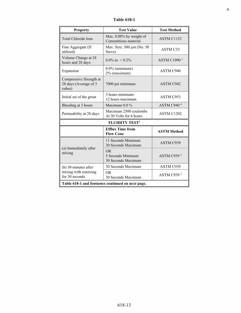
0
618-13
Table 618-1
Property Test Value Test Method
Total Chloride Ions Max. 0.08% by weight of Cementitious material ASTM C1152
Fine Aggregate (If utilized)
Max. Size: 300 µm (No. 50 Sieve) ASTM C33
Volume Change at 24 hours and 28 days 0.0% to + 0.2% ASTM C1090 1
Expansion 0.0% (minimum) 2% (maximum) ASTM C940
Compressive Strength at 28 days (Average of 3 cubes)
7000 psi minimum ASTM C942
Initial set of the grout 3 hours minimum 12 hours maximum ASTM C953
Bleeding at 3 hours Maximum 0.0 % ASTM C940 4
Permeability at 28 days Maximum 2500 coulombs At 30 Volts for 6 hours ASTM C1202
FLUIDITY TEST2
Efflux Time from Flow Cone ASTM Method
(a) Immediately after mixing
11 Seconds Minimum 30 Seconds Maximum ASTM C939
OR 5 Seconds Minimum 30 Seconds Maximum
ASTM C939 3
(b) 30 minutes after mixing with remixing for 30 seconds
30 Seconds Maximum ASTM C939 OR 30 Seconds Maximum ASTM C939 3
Table 618-1 and footnotes continued on next page.

618-14
Table 618-1 (continued)
Footnotes for Table 618-1 1 ASTM C1090 shall be modified to include verification at both 24 hours and 28 days. 2 Adjustments to flow rates shall be achieved by strict compliance with the manufacturer’s recommendations. 3 Grout fluidity shall meet either the Standard ASTM C939 flow cone test or the Modified Test described herein. Modify the ASTM C939 Test by filling the cone to the top instead of to the standard level. The efflux time is the time to fill a one-liter container placed directly under the flow cone. 4 ASTM C940 shall be modified to conform with the wick induced bleed test as follows:
(i) Use a wick made of a 20-inch length of ASTM A416 seven-wire 0.5-inch diameter strand. Wrap the strand with two-inch-wide duct or electrical tape at each end prior to cutting to avoid splaying to the wires when it is cut. Degrease (with acetone or hexane solvent) and wire brush to remove any surface rust on the strand before temperature conditioning.
(ii) Condition the dry ingredients, mixing water, prestressing strand and test apparatus overnight to 65 to 75 °F.
(iii) Mix the conditioned dry ingredients with the conditioned mixing water and place 800 ml of the resulting grout into the 1,000 ml cylinder. Measure and record the level of the top of the grout.
(iv) Completely insert the strand into the graduated cylinder. Center and fasten the strand so it remains essentially parallel to the vertical axis of the cylinder. Measure and record the level of the top of the grout.
(v) Store the mixed grout at the temperature range listed in (ii).
(vi) Measure the level of the bleed water every 15 minutes for the first hour and hourly for two successive readings thereafter.
(vii) Calculate the bleed water, if any, at the end of the three-hour test period and the resulting expansion in accordance with the procedures outlined in ASTM C940, with the quantity of bleed water expressed as a percent of the initial grout volume. Note if the bleed water remains above or below the top of the original grout height. Note if any bleed water is absorbed into the specimen during the test.
Grout used on the project shall have been sampled and tested within the last twelve months in accordance with the above referenced test procedures. The Contractor shall provide certified test reports for the grout used on the project from an independent AASHTO Accredited Laboratory and a sample of the grout for evaluation by the Department with the plan for grouting the ducts. The grout sample submitted to the Project shall be at least 2,000 grams in a sealed container. Grout that does not meet the above requirements shall not be used.
(c) Mixing of Grout. All grout shall be mixed with a high-speed shear (colloidal) mixer.
(d) Grouting. All grouting operations shall be performed under the immediate control of a person who has completed the American Segmental Bridge Institute (ASBI) Grouting Certification Training Program.
The Contractor shall perform the following tests and report the results to the Engineer:
(1) One pressure bleed test per day per lot in accordance with the requirements of Appendix C of the “Specification for Grouting of Post-Tensioned Structures” by the Post-Tensioning Institute. The Gelman filtration funnel shall be pressurized to a minimum of 50 psi and the maximum percent bleed shall be zero.

618.10
618-15
(2) Two mud balance tests per day or when there is a visual or apparent change in the characteristics of the grout in accordance with the API Recommended Practice 13B-1 “Standard Procedure for Field Testing Water-Based Drilling Fluids”.
(3) Minimum of one strength test per day per lot in accordance with ASTM C942 and the minimum 28-day compressive strength shall be 7,000 psi.
(4) Minimum of two fluidity tests (flow cone) – one at the mixer and one at the duct outlet in accordance with ASTM C939, “Standard Tests Method for Flow of Grout for Preplaced-Aggregate Concrete (Flow Cone Method)”. The efflux time shall be within the values established in Table 618-1.
Grout shall be injected from the lowest end of a tendon to the highest end in an uphill direction. A continuous, one-way flow of grout shall be maintained for each duct.
All grout vent openings shall be open when grouting starts. Grout shall be allowed to flow to the first vent from the inlet pipe until residual slugs of water or entrapped air have been eliminated and the grout has the same consistency as that of the grout being injected. The vent shall then be capped or otherwise closed. Remaining vents shall be capped or closed in sequence in the same manner except that at draped tendon high points, the secondary vents placed a short distance downstream from the high point vent shall be closed before the highpoint vent.
The Contractor shall inspect the interiors of box girders during grouting operations for grout leakage. Leaks shall be sealed before grouting is continued.
Grout shall be pumped through the duct and continuously wasted at the outlet pipe until all visible slugs of water or air are ejected. To ensure that the tendon remains filled with grout, the outlet shall be closed and the pumping pressure allowed to build to a minimum of 75 psi before the inlet vent is closed.
For all vertical tendons that are 20 feet and taller, a standpipe shall be provided at the upper end of the tendon to collect bleed water and allow it to be removed from the grout. This device shall be designed with commercial steel plumbing fittings so that the grout level will not drop below the elevation at the highest point in the upper anchorage device due to bleeding. If the level of the grout drops below the highest point in the upper anchorage device, additional grout shall immediately be added to the standpipe. After the grout has hardened, the standpipe shall be replaced with a cap.
For vertical internal tendons, if the grouting pressure exceeds the maximum recommended pumping pressure, the grout shall be injected at increasingly higher outlets (which become inlets) that have been or are ready to be closed as long as one-way flow of grout is maintained. Grout shall be allowed to flow from each outlet until all slugs of air and water have been purged prior to using that outlet for injection.
Plugs, caps, and valves thus required shall not be removed or opened until the grout has set.
The Contractor shall monitor all anchorages, grout ports, and vents periodically until the grout sets. The Engineer shall be notified if bleed water is dripping from these locations. Bleed water may be an indication of voids and will require investigation by the Contractor after the grout sets.
After the grout has set, the grout port and vent plugs shall be removed. The Contractor shall inspect the tendon anchorages, grout ports and vents for voids or other evidence of incomplete grouting. If evidence is found of voids in these areas, the Contractor shall submit a plan for regrouting the voids to the Engineer for approval. All costs for remedial grouting will not be measured and paid for separately but shall be included in the work.
(e) Temperature Considerations.
The temperature of the concrete adjacent to the ducts shall be 40 °F or higher from the time of grouting until site cured 2-inch grout cubes, tested in accordance with AASHTO T 106, reach a minimum compressive strength of 800 psi.
Grout shall be between 40 and 90 °F during mixing and pumping. If necessary, the mixing water shall be heated or cooled. Ice may be used to cool the water, but shall not be added directly to the mixed grout. Dry ice and liquefied carbon dioxide shall not be used for cooling purposes.
618.10 Equipment. Equipment used for fabrication of pretensioned and combination tensioned members shall conform to the following requirements:

618-16
(a) Jacking Equipment and Load Cells. All equipment shall be calibrated as a system that represents actual use. Jacks, gauge and pump systems, and load cells shall be calibrated at intervals not longer than 12 months, or whenever the tensioning system yields erratic results. Master gage systems shall be calibrated at intervals not longer than six months, or whenever the tensioning system yields erratic results. If load, sensor, or indicator components are replaced or repaired, the system shall be recalibrated before resuming jacking operations. System error shall not exceed plus or minus 1 percent of the applied loads.
Calibration shall be performed by an agency or service that uses equipment certified by the National Institute for Standards and Technology (NIST). Accuracy of the calibration equipment shall be traceable to the NIST records. The calibration procedures used shall conform to ASTM Standard Practices E 4 and E 74. Each time that calibration verification is performed, a copy of the certified test report shall be furnished to the QA Representative or the Engineer.
(b) Concrete Batching Equipment. The weighing system shall be calibrated at intervals no longer than 12 months. If disassembly, replacement, damage, or repair of scales or balance indicators should occur, the weighing system shall be recalibrated before resumption of mix operations. Scale calibrations shall be performed in conformance with the State of Colorado - Department of Agriculture requirements. Current calibration labels shall be visibly displayed on the equipment.
The batching system shall record the weights of all concrete mix ingredients for each batch. Ingredient weights shall meet the requirements of ASTM C94, Section 8, Measuring Materials.
The batching system shall be equipped with a flow meter which measures the weight or volume of the added mixing water within plus or minus 1 percent of the total water added to each batch.
(c) Concrete Load Testing Machine. The test machine shall meet the requirements of ASTM C39.
(d) Concrete Cylinder Molds. Molds shall meet the requirements of ASTM C470.
(e) Forms. Forms shall be sufficiently mortar tight to minimize fresh mortar paste leakage, and sufficiently rigid to prevent product distortion due to concrete pressure or consolidation operations. Form joints shall be kept clean, smooth, and adjusted to minimize form finish irregularities.
Forms shall be constructed and erected to produce units that conform to the product dimensional tolerances required by subsection 618.14(b); the forms shall also meet smoothness tolerances required by this subsection.
Forms shall be treated with a form release agent that does not adhere to or significantly discolor the final concrete product.
Forms that have known deviations from the typical sections shown on the plans shall be approved by the Engineer before use. The deviations shall be submitted on working or shop drawings.
(f) Miscellaneous Test Equipment. All miscellaneous test equipment used during fabrication shall be kept in a condition such that accurate test results are obtained. Proper equipment maintenance and calibration shall be the responsibility of the Contractor's PC section.
618.11 Concrete for Pretensioned and Combination Tensioned Products. The Contractor shall furnish and place concrete according to this subsection.
(a) Classification. Concrete shall be Class PS. Class PS concrete is used for prestressed concrete members. The required field compressive strength and air content shall be that stated on the plans. Class PS shall be made with an AASHTO M 43 size No. 8 or larger coarse aggregate. Class PS Concrete may be self-consolidating.
(b) Concrete Mix Components. The Contractor shall develop a mix design for Class PS concrete. The mix design shall conform to the requirements of Section 601 and CP-62. Materials sources shall be listed on the Contractor’s mix design. The PC manager must notify the QA Representative in writing before changing the sources as listed in the PCP. Changes in mix design material sources or proportions, except for admixtures, require a new mix design to be submitted to the Engineer for approval at least five days prior to the new mix being used in production.
(c) Equipment Calibration and Verification. The Contractor shall implement a plan for equipment calibration and verification of testing apparatus in compliance with ASTM C1077. The calibration records shall be made available to the QA Representative upon request.
(d) Batching and Mixing. Concrete shall be batched and mixed according to ASTM C94.

618.11
618-17
(e) Placing Concrete. Forms shall be free of dirt, mortar, debris, and foreign substances before depositing the fresh concrete. Rust areas shall be cleaned to prevent rust staining of the finished products. The concrete shall be consolidated with suitable mechanical vibrating equipment. Vibration time shall be of sufficient duration to accomplish adequate consolidation throughout the entire product, but shall not be prolonged to the point that segregation of the fresh concrete occurs.
The Contractor shall use the procedures listed in the PCP, to protect the freshly deposited concrete from rapid drying and surface moisture loss due to extreme ambient or climatic conditions.
Temperature limitations are as follows:
1. The temperature of the plastic concrete during placement operations shall not be lower than 50 °F.
2. Mid concrete that has a temperature in excess of 90 °F shall not be placed.
3. Unless a suitable retarder is used the concrete shall be deposited in place within 90 minutes after batching; any load or portion of a load shall not be placed after the 90-minute limit.
4. Inner form temperature shall be within 40 °F of the fresh concrete temperature at time of concrete placement.
5. Minimum inner form temperature shall be 32 °F and free of ice at the time of concrete placement.
6. Maximum inner form temperature shall be 130 °F at the time of concrete placement.
(f) Finishing Fresh Concrete. Open surfaces of fresh concrete shall be worked as little as possible to obtain the finish shown on the plans. Water shall not be added to the surfaces to ease finishing. Excessive water or laitance brought to the surface through vibration shall be removed before the surface is final finished. All hand finishing, required for precast members that have surfaces that become part of the final bridge deck surface, shall be performed in conformance with subsection 601.12(a).
Monomolecular film coatings or fogging systems, as approved by the QA Representative, may be used to retard evaporation during extreme ambient conditions. Application methods shall deposit a fine mist spray over the concrete surface. Streaming, puddling, or droplet application of coatings shall not be permitted. The concrete surfaces shall not be reworked after application of mist.
(g) Concrete Testing. The Contractor’s PC section shall make representative cylinder test specimens for PC/QA testing. The Contractor’s PC representative casting QA concrete cylinders shall be ACI Concrete Field Testing Technician – Grade I certified. When self-consolidating Class PS is used, the Contractor’s PC representative casting QA concrete cylinders shall also be ACI Self-Consolidating Concrete Testing Technician certified. The Contractor shall forward test cylinders to the QA representative, for 28-day strength tests, and for shipping strength tests as required by subsection 618.15. Concrete tests shall be performed in accordance with the following requirements:
1. Test cylinder specimens shall be prepared in accordance with ASTM C31. 2. Cylinders will be tested in accordance with ASTM C39 by the Engineer. The average strength of at least two test
cylinders shall be equal to or greater than the specified strength. When evaluating a single test consisting of three 28-day standard cured cylinders, if the compressive strength of any one cylinder differs from the average by more than 10 percent, that cylinder will be discarded and the average strength determined using the strengths of the remaining two cylinders. If the compressive strength of more than one cylinder differs from the average by more than 10 percent, all three cylinders will be used to determine the compressive strength. When the compressive strength of the concrete is less than that specified in the contract, the structural adequacy of the element will be evaluated by the Engineer. The Contractor may request to core the element represented by the low strength results. If approved by the Engineer, the locations of the cores shall be as directed by the Engineer. Coring shall be at the expense of the Contractor and witnessed by the Project Engineer or designee. Coring shall take place no more than 45 days after casting. A minimum of three cores shall be collected with a minimum diameter of 3 inches. The cores shall be obtained by the Contractor and immediately turned over to the Engineer for compressive strength testing. Cores shall be obtained in accordance with AASHTO T24 with the exception that immediately after removal from the structure, cores will be cured at a temperature between 60 to 80 °F and at a relative humidity below 60 percent for 24 to 48 hours prior to testing. When evaluating a single test consisting of three cores, if the compressive strength of any one core differs from the average by more than 10 percent, that core shall be discarded and the average strength determined using the strengths of the remaining two cores. If the compressive strength of more than one core differs from the average by more than 10 percent, all three cores will be used to determine the compressive strength. If the average core compressive strength is greater than the average of the cylinder compressive strength, the core strength will be used in the Engineer’s evaluation. If the core compressive strength is less than the cylinder compressive strength, the cylinder strength will be used in the Engineer’s evaluation.

618-18
Final determination of acceptance or rejection of the element shall be at the sole discretion of the Engineer based on evaluation of the cylinders and/or core strengths. If the element is accepted, the core holes shall be filled with a nonshrink grout or mortar approved by the Engineer. Patching of the core holes shall be at the expense of the Contractor/Fabricator.
3. Cylinder test specimens shall be made to verify stress transfer strength and to verify 28-day design strength. If the products will be shipped prior to 28-day testing, additional test specimens shall be available to verify product strength prior to shipment.
4. Representative cylinders shall be molded for each 50 cubic yards or portion thereof, for each different concrete mix design used per day per product line.
5. Air Content, when specified, shall be determined in accordance with either ASTM C173 or ASTM C231. Air entrained mixes shall be tested a minimum of once per day to assure specified air entrainment. This test shall be conducted for each load of concrete in which compressive strength specimens are cast in accordance with ASTM C39.
6. Slump of fresh concrete shall be determined in accordance with ASTM C143. The slump shall be tested whenever test cylinder sets are made. This test shall be conducted for each load of concrete in which compressive strength specimens are cast in accordance with ASTM C39. Slump testing is not required when self-consolidating Class PS concrete is used.
7. Unit Weight of fresh concrete shall be determined in accordance with ASTM C138. Unit weight shall be tested a minimum of once per day for each different concrete mix design used. This test shall be conducted for each load of concrete in which compressive strength specimens are cast in accordance with ASTM C39.
8. Temperature of fresh concrete shall be taken as needed, to assure compliance with the temperature requirements. This test shall be conducted for each load of concrete in which compressive strength specimens are cast in accordance with ASTM C39.
618.12 Curing.
(a) Pretensioned and Combination Tensioned Members. Members shall be uniformly cured from the time of concrete placement until at least two representative product test specimens achieve an average strength that meets or exceeds 0.7 f 'c, or the specified release strength, f 'ci, whichever is higher. Where:
f 'c = 28-Day Compressive Strength of Concrete
f 'c i = Required Concrete Strength at Release of Prestress Force
Additional curing requirements shall be maintained until the above strength requirements are achieved, and are as follows:
1. Exposed concrete surfaces shall be kept moist from the time of concrete placement until the freshly finished concrete is covered with an enclosure that retains heat and moisture. After enclosure, moist curing shall be maintained at a minimum 70 percent relative humidity.
The Contractor shall monitor the temperature and humidity conditions from the initial curing period through the end of the accelerated curing stage.
2. Temperature of the concrete shall be maintained above 50 °F.

618.13
618-19
3. The internal and surface temperature of the concrete shall not exceed 160 °F. The Contractor shall monitor the internal concrete temperature using thermocouples with concrete temperature recorded at intervals not to exceed 15 minutes. A minimum of two thermocouples shall be installed in the element at a maximum spacing of 75 feet with a maximum distance from either end of 40 feet. Thermocouples shall be installed at the center of mass of the element as uniformly as practical to provide accurate temperature monitoring information. An element is defined as a single precast prestressed concrete girder or beam or cast-in-place span. When multiple elements are cast simultaneously in a single bed, the temperature monitoring thermocouples shall be at a maximum spacing of 75 feet. Temperature logs shall be submitted to the Engineer prior to transporting the element to the project site. When the internal temperature of the element exceeds 160 °F, the Contractor shall submit a mitigation plan to ensure future castings do not exceed the 160 °F maximum temperature requirement. The mitigation plan shall also include procedures for sampling and testing the element to identify the potential risk for Delayed Ettringite Formation, and/or waterproofing applications to protect against moisture intrusion. The mitigation plan shall be submitted to the Engineer for review and approval. Acceptance or rejection of the element exceeding the temperature specification will be based on review and assessment of the specific curing temperature logs and the submitted documentation. The element shall not be shipped until the Contractor receives written acceptance from the Engineer.
4. Concrete shall attain initial set prior to application of the accelerated curing cycle. If initial set was not determined in accordance with ASTM C403, accelerated curing shall not be induced for 4 hours, or 6 hours if retarding admixtures are used.
While waiting for the initial set period, low cycle heat may be applied to maintain the curing chamber temperature; however, the temperature rise shall not exceed 10 °F per hour during the waiting period.
5. The rise in temperature in the curing chamber during accelerated curing cycle shall not exceed 40 °F per hour.
(b) Cast-in-Place Members. The curing of cast-in-place members shall conform to the requirements of subsection 601.13. The concrete shall not be exposed to temperatures below freezing for six days after casting, or until it has reached the strength required for applying the prestressing force. The minimum strength of the concrete shall be at least, 3,500 psi for post-tensioned members, or as given on the plans whichever is greater, before prestressing.
(c) Other Precast Members. Precast members that do not contain pretensioned steel shall meet curing requirements as follows:
1. Exposed surfaces of freshly finished concrete shall be covered with moisture retaining material, or shall be treated with a concrete curing compound approved by the QA Representative.
2. Temperature of the concrete shall be maintained above 50 °F from the time of concrete placement until the curing is complete.
3. Uniform curing shall continue until at least two representative product test specimens achieve an average strength that meets or exceeds 0.7 f 'c or the specified release strength f 'c i, whichever is higher.
4. The internal and surface temperature of the concrete shall not exceed 160 °F.
618.13 Repairs of Pretensioned and Combination Tensioned Members. Repairable product defects discovered during PC or QA inspection shall be corrected at the Contractor’s expense prior to shipping. Damage incurred during handling, storage, shipment and erection shall be repaired or replaced at the Contractor’s expense.
Defects shall be categorized as minor, structural, or rejectable. The PC section shall examine and record all defects. The PC section shall submit a written proposal for minor repairs to the QA Representative for review and acceptance prior to correcting the minor defects. The proposal shall also address the measures the Contractor will take to prevent recurring defects in future members. The QA Representative will accept, or reject, the finished repair work in writing.
Small production holes that are less than 1/2 inch in depth and less than 1 square inch in surface area shall not be considered defects. Larger production holes shall be repaired according to the procedures listed in the PCP.
Structural and rejectable defects shall be examined by the Contractor's Engineer. A written proposal for repair of structural or rejectable defects shall be submitted to the QA Representative for review and acceptance prior to correcting any defects. The proposal shall include a detailed description of repair materials, and the methods the Contractor intends to use to evaluate the finished repair work. The proposal shall also include the measures the Contractor will take to prevent recurring defects in future members.
Completed repairs shall be cured as needed to ensure soundness of the reworked area.
The defect categories and repair requirements are defined as follows:

618-20
(a) Minor Defects. Minor defects are those that do not affect the ability of the product to withstand service or construction loads. Minor defects include superficial discontinuities such as cracks; small spalls, voids, and honeycombed areas; and defects that do not extend beyond the centerline of any reinforcing steel or into any elements of the tensioning system. Minor defects of other types may also be designated by the QA Representative.
Repair methods shall not affect the structural integrity of the product. The finished repair work shall meet the approval of the QA Representative and the Engineer.
(b) Structural Defects. Structural defects, as determined by the QA Representative or the Engineer, include defects that may impair the ability of the product to adequately withstand construction or service loads. Defects that extend beyond the centerline of any reinforcing steel or into any element of the tensioning system are classified as structural defects. Such defects also include cracks, spalls, honeycombed areas, voided areas, significant concrete breakage areas, cold joints, and segregated concrete areas. Structural defects of other types may also be designated by the QA Representative or the Engineer.
The Contractor’s Engineer shall electronically seal a letter that the repair work meets all design serviceability criteria and include the evaluation and test data. Repair Methods shall adequately restore the structural integrity of the product. The finished repair work, including aesthetic acceptability, shall meet the approval of the Engineer.
(c) Rejectable Defects. Rejectable defects or damages, as determined by the QA Representative or the Engineer, are those which impair the ability of the product to adequately withstand construction or service loads, and which cannot be successfully repaired to structural and architectural acceptability. Structurally defective or rejected products shall not be incorporated into the work but shall be replaced with acceptable products supplied at the Contractor's expense.
Damaged and defective products will also be rejected by the QA Representative for the following reasons:
1. Failure by the Contractor's Engineer to approve and submit proposed repair procedures in writing before repair work begins.
2. Failure by the Contractor to execute the repair work according to QA approved procedures.
3. Failure by the Contractor to provide written certification of acceptable structural repair, along with submittal of evaluation and test data, if applicable.
4. Failure by the Contractor to correct recurring defects.
5. Determination by the QA Representative that the work, or materials used in the work, does not meet all contract requirements.
618.14 Other Fabrication Requirements for Pretensioned and Combination Tensioned Members.
(a) Finishing Hardened Concrete Products. Finished and repaired areas shall reasonably match the coloration and profile characteristics of the adjacent concrete. Loose concrete laitance shall be removed from the product before storage.
(b) Product Dimensional Tolerances. Tolerances for prestressed concrete products shall meet the unit tabulations listed in the PCI Manual MNL-116, unless otherwise stated in the Contract. The PCI tolerance figures and tabulations shall be specification requirements. Out-of-dimensional-tolerance variations shall be considered defects and shall be examined and evaluated by the Contractor's Engineer. The evaluation shall be submitted to the QA Representative in writing and shall contain written opinion of structural adequacy as determined by the Contractor's Engineer. The submittal shall meet the approval of the Engineer. Failure to submit the written evaluation and opinion will be cause for rejection.
The following work or products shall meet the specific PCI tolerance requirements described as follows, unless otherwise specified in the plans:
(1) Bulb-Tee Sections shall conform to Division VI, I-Beams.
(2) G-Series Sections shall conform to Division VI, I-Beams.
(3) Box Girders and U-Girders shall conform to Division VI, Box Beams.
(4) Deck Panels shall conform to the dimensional tolerances as listed in the PCI Special Report JR-343-88, Chapter 4, or the updated published edition thereof.

618.14
618-21
(c) Handling, Storage, Shipment and Erection. The Contractor shall handle the product in such a manner as to prevent cracking or damage. Cracked or damaged products shall be inspected by the PC section and repaired in accordance with subsection 618.13, or replaced at the Contractor's expense.
Braces, trusses, chains, cables, or other metal devices used for handling, storing, shipping, or erecting shall be adequately padded at points in contact with the concrete, to prevent chipping of the finished product.
Beam sections shall be handled, stored, shipped, and erected with supports and devices that maintain the product in an upright position. Deck panels shall be lifted as directed in the Contract unless alternative lifting methods are allowed by the Engineer. Lifting of more than one panel at a time shall not cause panel cracking. Methods for multiple lifting of panels shall be shown on the working or shop drawings. Panel products shall be stacked in such a manner that damage does not occur.
Pre-cast concrete members shall be erected to prevent damage to all elements of the structure and in a safe manner. Pre-cast concrete members to which the erection specification applies are those members that bear on the substructure of a bridge. The primary members such as beams and girders shall be temporarily anchored and braced as they are erected to preclude detrimental movement in any direction, and to prevent overturning and buckling. Struts, bracing, tie cables, and other devices used for temporary restraint shall be considered falsework and shall be designed to resist all loads imposed during each stage of construction until the deck concrete has attained the Field Compressive Strength shown in Table 601-1.
At least one week prior to the Pre-erection Conference, the Contractor shall submit an Erection Plan to the Engineer. The Engineer will review the and return comments within one week. The Contractor shall address the Engineer's comments in the final plan. The Contractor’s Engineer shall electronically seal and mark the Final Erection Plan "Approved for Construction".
If falsework is required, falsework drawings shall conform to and be submitted in accordance with subsection 601.11.
The Erection Plan and procedure shall provide complete details of the erection process with dimension tolerances including:
(1) Falsework, struts, bracing, tie cables and other devices, material properties and specifications for temporary works, bolt torque requirements prior to releasing girders from the cranes (if required), connection details and attachments to other structure components or objects;
(2) Procedure and sequence of operations, including a detailed schedule with completion times for work items that complies with the working hour limitations;
(3) Minimum load chart lift capacity, outrigger size, and reactions for each crane;
(4) Assumed loads and girder weights, lift points, lifting devices, spreaders, and angle of lifting cables;
(5) Girder stresses at critical points along the girder length during progressive stages of erection shall be investigated to assure that the structural integrity and stability of the girders is maintained. Stresses at lift points induced as a result of lifting shall be investigated and adequate bracing provided as indicated by the analysis;
(6) Locations of cranes, trucks delivering girders, and the location of cranes and outriggers relative to other structures, including retaining walls, wingwalls and utilities;
(7) Drawings, notes, catalog data showing the manufacturer’s recommendations or performance tests, and calculations clearly showing the above listed details, assumptions, and dimensions; and
(8) Contingency plans detailing what measures the Contractor will take in case of inclement weather (forecast or actual), equipment failure, delivery interruption, and slower than planned production.
A Pre-erection Conference will be held at least one week prior to the beginning of erection. The Engineer, Contractor, erection subcontractor, and the Contractor’s Engineer shall attend the meeting. The erection subcontractor shall review and verify that the piece marks are properly located on the components to be erected, their orientation in the erected structure, and the shop drawing piece mark convention used by the girder fabricator at the Pre-Erection Conference. The girder fabricator shall either attend the meeting or participate in the conference by way of speaker telephone. Participation is required during that portion in which the piece marks are discussed. The girder fabricator shall state whether the erection subcontractor has demonstrated a correct understanding of the piece marks, and if not, correct any misunderstanding.
Additional Pre-erection Conferences may be required for subsequent phases of construction, or for phases that differ from the original construction plan, as directed by the Engineer. Additional conferences may also be requested by the Contractor, if approved by the Engineer.

618-22
The Contractor shall submit a final Erection Plan to the Engineer prior to girder erection for acceptance. The Contractor’s Engineer shall electronically seal (1), (5) and (7) listed above in the final Erection Plan. The final Erection Plan shall be stamped “Approved for Construction” and signed by the Contractor. The Contractor shall not proceed with the Erection Plan until the Engineer has provided written acceptance of the plan.
When a bridge spans traffic of any kind, including those where vehicles, railroad, watercraft, or pedestrians have access onto, underneath, or adjacent to the bridge, the Contractor’s Engineer shall inspect and provide electronically sealed written approval of the stability of the erected girders prior to opening the area beneath the girders to traffic. The Contractor shall perform daily inspections of the erected girders and other permanent and temporary bridge elements until the deck concrete has attained the full design compressive strength. The Contractor’s Engineer shall provide an inspection form to the Engineer that lists the items the Contractor will document during the daily inspection of the erected girders. The inspection form shall include inspection items specific to each bridge being constructed. The Contractor shall provide the Engineer and the Contractor’s Engineer with written documentation of these inspections within 24 hours of each inspection.
All temporary struts, bracing, tie cables, other devices and extra material required shall be removed upon completion of the structure.
Falsework shall conform to subsection 601.11.
618.15 Product Shipping Strength for Pretensioned and Combination Tensioned Members. Products shall not be shipped before concrete strength meets or exceeds 0.95 f 'c. The average of at least two representative test specimens shall meet or exceed 0.95f 'c. No individual specimen strength shall be more than 7 percent below 0.95f 'c. The shipping strength test specimens shall be cured in the same environment as the actual product until the time of testing. The QC section shall test the specimens for actual shipping strength. The QA Representative may independently verify any shipping strength tests.
The Contractor may elect to take concrete cores from the actual product in lieu of curing cylinder test specimens with the product. If the Contractor chooses this test option, the QC Manager shall submit written request to the QA Representative. Core extraction shall not begin until the request has been accepted in writing by the QA Representative. The written request shall include the proposed location and time schedule for core extraction and testing.
The cores shall be delivered in a wrapped and moist condition to the certified test laboratory as listed in the PCP. The QA Representative may witness any or all stages of the core testing operations. The test laboratory shall provide a copy of the formal test report to the QA Representative.
The Contractor shall bear all expenses associated with the optional core testing requirements. Sampling and testing of the concrete core specimens shall conform to ASTM C42 with the following addenda:
(1) Samples may be removed at any age at the Contractor’s sole risk of damage.
(2) Test cores shall not contain embedded reinforcement.
(3) A minimum of three core samples shall be taken from the product casting in question. Three specimens shall be tested for compressive strength. The average compressive strength of the three tests shall meet or exceed product f(c). If the compressive test result of any specimen differs from the average strength by more than 15 percent, those results shall be disregarded, and the compressive strength shall be determined from at least two remaining valid test results.
(4) If end capping of test specimens is necessary, the capping shall be done with sulfur mortar in accordance with ASTM C617. Specimens shall be kept moist until end-capping preparation begins.
Ends shall be trimmed or prepped as required, wiped with absorbent cloth and air-dried or fan-dried to prepare for end capping. The drying period shall not exceed 20 minutes before capping is completed.
Specimens shall be air-dried for 10 to 20 minutes after capping, and then wrapped with a double layer of wet, thick cloth or burlap. Compressive testing shall not be started for at least one hour after wet-wrapping. The wrapped specimens shall be kept moist until compressive testing begins.
The Contractor shall submit a written repair proposal to the QA Representative for patching the core holes. Repair work shall not begin until the proposal is accepted in writing by the Engineer.

618.16
618-23
METHOD OF MEASUREMENT
618.16 Prestressed units will be measured by one of the following methods as indicated in the Contract.
(1) Prestressed girders will be measured by the linear foot from end to end or by the square foot, based on the plan length multiplied by the plan width, whichever is specified on the plans.
(2) Prestressed concrete box girders and prestressed concrete slabs will be measured by the square foot based on the plan length multiplied by the plan width.
(3) When measured by component materials, concrete and reinforcing steel will be measured and paid for in accordance with Sections 601 and 602 respectively.
The quantities of prestressing steel will not be measured but shall be the quantities shown on the plans, completed and accepted. MKFT equals the jacking force, in thousands of KIPS, times the length in feet.
Precast panel deck forms that are required by the plans will be measured by the square foot. The quantity will not be remeasured, but will be the quantity shown on the plans, except when a plan change is ordered or when it is determined that there are discrepancies in an amount of plus or minus two percent of the plan quantity.
BASIS OF PAYMENT
618.17 The accepted quantities of prestressed units and prestressing steel will be paid for at the contract unit price per unit of measurement for each of the pay items listed below that is included in the bid schedule. Precast panel deck forms required by the plans will be paid for at the contract unit price for the area shown on the plans.
Payment will be made under:
Pay Item Pay Unit Prestressing Steel Bar Pound or MKFT Prestressing Steel Strand Pound or MKFT Prestressed Concrete ___ (___) Linear Foot or Square Foot Prestressed Concrete Box (___) Square Foot Prestressed Concrete Slab (Depth _______) Square Foot
Payment will be full compensation for all work necessary to complete the designated pay item.
Prestressing steel bar and prestressing steel strand shall include but not be limited to all anchorage devices, prestressing steel, ducts, grout, and miscellaneous hardware. Elastomeric leveling pads, and galvanized steel diaphragms and connectors will not be paid for separately, but shall be included in the work. Concrete and reinforcing steel not shown on the plans but required by the Contractor’s alternative will not be paid for separately but shall be included in the work. All required testing will not be paid separately but shall be included in the work.
Concrete quantities will not be reduced for the volume occupied by the ducts, prestressing steel, anchorages, blockouts for tensioning, etc., and will not include web flares, projections, warts, etc., required to accommodate the prestressing system used.
All costs associated with the preparation and implementation of the Erection Plan will not be paid for separately, but shall be included in the work.
Concrete, reinforcing steel, and prestressing steel for permanent steel bridge deck forms will not be measured and paid for separately, but shall be included in the work.

618-24
THIS PAGE INTENTIONALLY LEFT BLANK

619.01
619-1
Section 619SECTION 619 WATER LINES
DESCRIPTION
619.01 This work consists of the construction of water lines in accordance with these specifications, the latest revision of the American Water Works Association Standards and in conformity with the lines and grades shown on the plans or established.
This work also includes furnishing welded steel pipe and installing it by jacking it into place at the location and in conformity with the lines and grades shown on the plans.
MATERIALS
619.02 Materials shall meet the requirements specified in the following subsections:
Cast Iron Pipe 716.01 Welded Steel Pipe 716.02 Galvanized Pipe 716.03 Copper Pipe 716.04 Plastic Pipe 716.05 Valves and Valve Boxes 716.07
Specific type of material, when required, will be shown on the plans or as designated.
The maximum working water pressure will be shown on the plans.
Welded steel pipe, when used as a casing and not as a carrier pipe, will not require full depth welds or welds from both sides, and will not require coatings. Sections of the casing shall be welded firmly together on the inside to prevent separation. Certification of the welder/operator will not be required.
CONSTRUCTION REQUIREMENTS
619.03 Trench shall be excavated to a width sufficient to allow for proper jointing of the water line and thorough compaction of the backfill material in accordance with Section 206.
Where ground water occurs, the bottom of the trench shall be kept free of water during pipe laying and until backfilled.
Backfilling shall consist of suitable materials uniformly distributed in layers of not more than 8 inches.
Each layer shall be thoroughly compacted as required. All joints, connections, valves and fittings shall be watertight.
(a) Jacked Pipe. The term “jacking” as used herein shall mean jacking, boring,' or other approved construction methods. Method of installing pipe other than jacking may be used only with written approval from the Engineer. Trenching, jetting, or any other method that may cause damage to the embankment or highway area, or be hazardous to the traveling public will not be permitted. When jacking is specified, the pipe must be jacked without disrupting highway traffic.
The sides of the jacking pit shall be supported in such a manner as to prevent any movement or slippage of the earth during the jacking operations.
A jacking frame shall be constructed of guide timbers or rails to the exact line and grade of the casing and shall be capable of maintaining the desired alignment and gradient throughout the jacking operation.
Depending upon the soil conditions, the excavation operation inside the pipe shall proceed approximately 1 foot ahead of the lead pipe. The excavation around the pipe shall be cut accurately to line and grade and as reasonably close to the outside diameter of the pipe as possible.
Each section of pipe in its final position shall be straight and true in alignment and grade. Deviation in alignment and grade from beginning to end of the jacked pipe shall not exceed plus or minus 0.3 foot per 100 feet of length.
(b) Reserved

619-2
METHOD OF MEASUREMENT 619.04 Water lines of the various types and sizes will be measured by the linear foot in place and shall include all fittings. Valves including valve boxes will be measured by the actual number of the specified type and size used in the completed water lines, and accepted.
The quantity of jacked pipe will be measured by the linear foot complete in place and accepted.
BASIS OF PAYMENT 619.05 The accepted quantities of water line will be paid for at the contract unit price for each of the pay items listed below that appear in the bid schedule.
Payment will be made under:
Pay Item Pay Unit ______ Inch Cast Iron Pipe Linear Foot ______ Inch Welded Steel Pipe Linear Foot ______ Inch Galvanized Pipe Linear Foot ______ Inch Copper Pipe Linear Foot ______ Inch Plastic Pipe Linear Foot ______ Inch (Type) Valve and Valve Box Each ______ Inch Welded Steel Pipe (Jacked) Linear Foot
Structure excavation and structure backfill for lines 12 inch and less will not be measured and paid for separately but shall be included in the work. Structure excavation and structure backfill for lines larger than 12 inch will be measured and paid for in accordance with Section 206.
All work incidental to installing jacked pipe will not be measured and paid for separately but shall be included in the work.

620.01
620-1
Section 620SECTION 620 FIELD FACILITIES
DESCRIPTION
620.01 The Contractor shall furnish field offices, sanitary facilities and field laboratories when called for on the plans or as directed. These units are to be maintained by the Contractor and shall be removed when the project is completed unless released earlier by the Engineer.
MATERIALS
620.02 Field Offices. Field offices, either Class 1 or Class 2 as designated on the plans, shall substantially conform to the details shown on the plans and to the requirements of this section.
The field office shall be equipped with a facsimile machine, copy machine, and telephone service that conform to the following:
(1) Facsimile Machine. The facsimile machine shall print on plain paper and shall be capable of sending 8 1/2 x 11 inch and 8 1/2 x 14 inch documents. The Contractor shall install and maintain the fax machine in the Engineer’s field office. Should the fax require repair and be out of service for more than 24 hours, a replacement machine shall be supplied within 24 hours. The Contractor shall supply all necessary supplies, except paper, and a roll-around stand. Paper will be provided by the Department.
(2) Copy Machine. The Contractor shall provide a self-feeding plain paper photocopier, which is capable of making at least eight copies per minute. Copier shall also be capable of reproducing copies at standard sizes up to and including 11 x 17 inches. The copier shall be capable of reducing 11 x 17 plan sheets to 8 1/2 x 14 legal size and to 8 1/2 x 11 letter size. The Contractor shall supply all necessary supplies, except paper, and a roll-around stand. Paper will be provided by the Department. The Contractor shall maintain all furnished equipment in good working condition and shall provide replacement equipment due to breakage, damage, or theft within five work days.
(3) Telephone Service. The Contractor shall provide telephone service as required by standard plans. This service shall include a long distance carrier. The Department will be responsible for actual long distance toll charges.
620.03 Field Laboratories. Field laboratories, either Class 1 or Class 2 as designated on the plans, shall substantially conform to the details shown on the plans and to the requirements of this section.
Each laboratory shall be qualified in accordance with CP 10.
620.04 Commercial Plant Laboratory. The plant laboratory at the site of the commercial hot mix plant shall consist of weatherproof, insulated, mobile house-type trailer or other approved structure having equipment meeting the following minimum requirements.
Each laboratory shall be qualified in accordance with CP 10.
(1) Outside Dimensions: 28 feet long x 12 feet wide if a separate facility is provided, or inside area of 175 square feet with a minimum width of 7 feet when not a separate facility
(2) Drinking Water Supply: Dispensed from an acceptable water cooling device
(3) Testing Water Supply: 100 gallons, insulated and pressurized by pump, minimum 30 psi delivery pressure
(4) Shelving: 24 linear feet
(5) Sink: One, with faucet
(6) Fire Extinguisher: One, non-toxic, dry chemical, meeting Underwriters Laboratories, Inc. approval for 10-pound class ABC with 20 BC rating
(7) Work Bench: 19 feet x 30 inches x 36 inches high
(8) Lighting: Adequate fluorescent lighting directly over all work bench and desk areas
(9) Range: One, 30-inch free standing, oven with reinforced racks, and four surface burners
(10) Forced Air Convection Oven: Rated at least 1,500 watts
(11) Sieve Shaker: One, motor-driven, standard portable, capable of handling a set of 8 inch or 12 inch US standard sieves, mounted 24 inches above floor in a soundproof, insulated enclosure having hinged openings

620- 2
(12) Heating: Furnace, 200 BTU per square foot, minimum, forced air type
(13) Telephone: Minimum flat rate service from nearest exchange
(14) Air Conditioner: Adequate for laboratory size
(15) Furniture: Desk with at least one drawer. One desk chair with rollers. One stool with height compatible with work bench
(16) Electronic Balance: Balance complying with AASHTO M 231 capable of weighing at least 35 pounds to an accuracy of 0.2 gram
(17) Recording Thermometer: Electrical or mechanical thermometer for curing tanks
(18) Microwave Oven: One, 1.5 cubic foot, with at least five power levels, and revolving floor or rotating power source
620.05 Sanitary Facilities. Sanitary facilities shall consist of a portable chemical toilet fabricated from steel, fiberglass or wood, meeting the following minimum requirements:
Each facility shall be well ventilated, conform to State law, have a vented chemical tank, and a separate urinal.
CONSTRUCTION REQUIREMENTS 620.06 The Contractor shall furnish a suitable site for field facilities. The site may be located within the right of way with approval of the Engineer. If located within the right of way, the Contractor shall be responsible for restoring the area.
Facilities shall be on the project, leveled and ready for use prior to the start of any operations. Facilities shall be for the exclusive use of Department personnel.
Sanitary facilities shall be placed at least 50 feet from the nearest State Water, in locations accessible for servicing, and not in low-lying areas subject to ponding. They shall be anchored to prevent movement or overturning.
The Contractor shall provide replacement equipment due to breakdown, damage, or theft within five work days.
620.07 Maintenance, Service and Utilities. The Contractor shall furnish the following:
Fuel: Adequate supply for heating and testing operations. Electricity: A 3,000 watt, 115-125-volt AC facility for each field office and field laboratory. Independent generators shall be provided where commercial power is not available. Telephone: Minimum flat rate service from nearest exchange for each field office and field
laboratory as directed. Sanitary: Sanitary facilities shall be serviced and maintained in a sanitary
condition. Trash: The Contractor shall provide and maintain suitable containers and shall haul away as
necessary.
METHOD OF MEASUREMENT AND
BASIS OF PAYMENT 620.08 The various facilities complete with utilities, will be measured and paid for at the contract unit price for each of the pay items listed below that appear in the bid schedule.
Payment will be made under: Pay Item Pay Unit Field Office (Class______) Each Sanitary Facility Each Field Laboratory (Class______) Each
Payment will be full compensation for Field Laboratory (Class1) or (Class 2), including all appurtenant items specified in the Contract. Restoration of the field facility areas will not be paid for separately, but shall be included in the cost of the item.

622.01
622-1
SECTION 622
REST AREAS AND BUILDINGS
DESCRIPTION
622.01 This work consists of the construction of various facilities in rest areas and other areas in accordance with these specifications and in conformity to the lines, grades, dimensions and details shown on the plans or established.
When information shown on the plans are of general arrangements only, the Engineer will establish exact locations, measurements, levels, etc., at the site to adapt the work to suit actual conditions.
MATERIALS
622.02 All materials used in the construction shall conform to the requirements of Section 717 and to the details shown on the plans or established.
622.03 Shop Drawings and Descriptive Brochures. At the Pre-construction Conference, the Contractor shall submit to the Department five copies of shop drawings or descriptive brochures for all materials and equipment to be incorporated in the work for review by the Engineer.
All work for which shop drawings or descriptive brochures are required must be performed in accordance with such drawings, and work on the item shall not be started until review of said drawings.
All shop drawings or descriptive brochures must be complete in every respect, numbered consecutively, have the name of the project printed thereon, and each transmittal must be accompanied by a letter directing the Engineer's attention to any changes from the plans.
After shop drawings and descriptive brochures have been reviewed, any portion of the work covered by the shop drawings that modify the plans shall be rejected as soon as such modification is discovered unless said modification has been specifically pointed out to the Engineer review.
The review of such shop drawings and descriptive brochures will be general in character and shall not relieve the Contractor from responsibility for their accuracy or for proper fitting and construction of the work, or from the necessity of furnishing any materials and workmanship required by the Contract, which may not be indicated on shop drawings when reviewed.
622.04 Construction Material. Structure excavation and structure backfill shall conform to the requirements of Section 206. Treated timber shall conform to the requirements of Section 508. Concrete shall be Class "B" and conform to the requirements of Section 601. Reinforcing steel and fabric shall conform to the requirements of Section 602.
CONSTRUCTION REQUIREMENTS
622.05 Services of Factory Representative. It is important that the Department be protected as far as possible against the discontinuance of the make of equipment to be purchased, and that repair parts and the services of expert factory representatives be available if desired. Under these conditions the Contractor shall not furnish equipment made by firms in the hands of receivers.
622.06 Maintenance Manuals. The Contractor shall furnish to the Engineer five copies of instructions for the operation, lubrication and maintenance for all major items of equipment. The Contractor shall assemble all literature into five coordinated manuals with additional information describing the combined operation of field-assembled units, including as-constructed wiring diagrams. Manuals shall also contain the names, addresses of the manufacturer, and the local representative who stocks or furnishes repair parts for all items of equipment. All five manuals shall be turned over to the Engineer for review and distribution to the Department. Manuals shall include but not be limited to the above information for the following equipment: Furnace, water heater, well pump, exhaust fan, incinerators, timer, septic tank, emergency battery charger, and area luminaires.
622.07 Temporary Heat. All heating and electrical service required during construction for the satisfactory prosecution of the work shall be furnished by the Contractor. Heating units must be of approved types, and equipment and surroundings shall be kept in a clean and safe condition. Open fires will not be permitted.
622.08 Temporary Utilities.
(a) Water for Construction Purposes. The Contractor may use water pumped by the permanent well pump and equipment, if approved by the Engineer. The Contractor shall provide potable water for construction purposes at his expense. If temporary pumps are approved, all sanitary precautions necessary to prevent contamination of the well shall be taken.

622-2
(b) Electrical. The Contractor shall furnish at his expense, all electrical power required for construction.
622.09 Barricades. When required, the Contractor shall barricade the entrance ramp to the rest area during construction with standard barricades. The barricades will not be paid for separately but shall be included in the work.
622.10 Masonry Work.
(a) Installation of Masonry. Concrete masonry units shall be placed in face shell mortar bedding with complete coverage of face shells. Extruded mortar shall be struck. After the mortar has stiffened somewhat, all joints shall be tooled with a rounded tool having a diameter slightly larger than the thickness of the joint. Mortar joints shall average 3/8 inch in thickness. Blocks shall be placed in accordance with local standard masonry practice. Reinforcement and wall ties shall be installed as indicated on the plans.
Standard shapes of concrete masonry units such as radius, corner, jamb blocks, control joint blocks, bond course units and square end blocks, shall be furnished as required by the Contract.
Structural glazed tile in toilets shall be placed with white mortar. Mortar joints shall not exceed 1/4 inch in thickness. All joints shall be tooled.
The Contractor shall furnish cap courses, base courses, covings, bull-nosed corners and any special units necessary to complete a first class job. Special shapes of tile required are shown on the plans.
When cutting of tile is necessary, it shall be done with a special saw as recommended by the manufacturer. Chipped, warped or defective tiles will be rejected.
All face brick shall be placed with joints about 3/8 inch thick. Joints shall be concave tooled joints.
Brick will be rejected if the edges and corners of finished faces have chippage exceeding the following maximum sizes: Edges 5/16 inch (measured in from edge) and corners, 1/2 inch (measured in from edge), or for any other structural or color defect.
Each brick shall be placed in a full bed of mortar and shall be shoved in place. The Engineer may remove brick already placed to assure himself that all joints are full. If he finds joints that are not completely filled, he can order brick removed until he is assured that the joints of all remaining brick are completely filled.
All face surfaces of the face brickwork shall be kept clean. After joints are struck, the surface shall be carefully cleaned.
The faces and angles of all walls shall be carefully plumbed and all work carried up true and even, laying all walls to lines.
(b) Precautions and Protection. All work and materials shall be protected from the weather. Stored masonry units shall be stockpiled on planks to prevent contact with the ground.
(c) Masonry Work in Cold Weather. Masonry shall not be placed when the surrounding air temperature is 40 °F or less, except when the masonry work is housed in a temporary manner, suitable to the Engineer, and the inside air temperature is kept within 40 °F to 80 °F for a period of 24 hours after the masonry is placed. Mortar for masonry work during cold weather shall have a minimum temperature of 50 °F and a maximum temperature of 100 °F at the time it is applied to the masonry. This temperature shall be provided by heating the mixing water or the aggregate or both if necessary. Masonry materials shall also be heated, if necessary, to provide at least a minimum temperature of 40 °F at the time they are placed.
(d) Cleaning. After completion, all masonry units shall be thoroughly cleaned according to the masonry manufacturer’s recommendations. The Contractor shall protect adjacent work from damage during the cleaning operations.
Cleaning shall start at the top and be continued down until such work is completed. All pointing will be inspected and the Contractor shall completely point up all voids.
622.11 Metal Specialties. Metal stalls or compartments for toilet rooms and mirrors shall be of the type and style specified and shall be installed as shown on the plans.
622.12 Sanitary Napkin Disposal. Sanitary napkin dispenser and disposal for Women’s Rest Rooms shall be installed as shown on the plans and in accordance with the manufacturer's recommendations.
622.13 Comfort Station and Sanitary Station Signs. Comfort Station and Sanitary Station Signs shall be installed in the size and location shown on the plans.

622.14
622-3
622.14 Doors, Frames and Windows. Doors, frames, windows and door hardware shall be installed as shown on plans.
All doorframes shall have floor anchors installed to set flush with the finished floors. Two rubber door silencers shall be installed for strike jambs of each door. At least three masonry “T” anchors shall be installed at each jamb that is adjacent to masonry work.
622.15 Ceramic Tile.
(a) General. The work required under this heading shall include all labor, material, equipment and services necessary for the furnishing and setting of all tile as shown on the plans and as specified herein. The floor slab shall be clean and free of oily or waxy films.
(b) Installation of Ceramic Floor Tile.
1. Mortar Setting Bed. A mortar setting bed shall be applied over the floor slab to give a true and even setting bed. This mortar shall be composed of one part portland cement, six parts sand.
2. Setting Floor Tile. Floor tile shall be set by troweling a skim coat of neat portland cement mortar on the setting bed and immediately floating the tile into place. Joint width shall not exceed 1/16 inch.
3. Grouting. All joints in ceramic floor tile shall be grouted full with a grout mixture and application as recommended by the tile manufacturer immediately after a suitable area of tile has been set. A 1/8 inch bronze edging strip shall be provided under the metal thresholds where the ceramic floor tile terminates at the door.
4. Defective Tiles. All tiles chipped, broken, stained or otherwise imperfect, shall be considered defective, and shall not be set; any such defective tiles set shall be removed and replaced with approved tiles at the Contractor's expense.
5. Cleaning. Upon completion of the work, all tile shall be thoroughly cleaned and left free from stains, scum, discoloration, and in an acceptable condition.
622.16 Roofing, Flashing and Roof Insulation. The work required under this heading shall include all labor, material, equipment and services necessary for the proper furnishing and installing of all roofing, flashing and insulation materials as shown on the plans.
(a) Flashing at Flues, Breather Vents, Vents, Roof Drains and Emergency Light Conduit. Flashings at sewer vent and roof drain shall be at least 2 feet square lead flanges soldered to lead sleeves of sufficient diameter to fit the pipe involved, placed over the last layer of felt and sealed in place with two plies of felt, hot mopped in place. The specified roofing shall be applied over this. At the vent, the lead sleeve shall be folded over the top of the 4-inch soil pipe. At the roof drain, the lead sleeve or flange shall be securely clamped in place to make a watertight joint. Other means of flashing may be used if approved. Flashing at emergency light and breather vents shall be as detailed on the plans or directed.
All flashing shall be installed before roofing operations begin.
(b) Roofing Construction (Shingle Roofing). Shingles as shown on the plans shall be applied over two layers of 15-pound asphalt felt in straight courses. Shingles shall be doubled at all eaves, and butts of first-course shingles shall project 1 1/2 inch beyond the first sheathing board. Spacing between adjacent shingles (joints) shall be 1/4 inch. Joints in any one course shall be separated at least 1 1/2 inches from joints in adjacent courses and joints in alternate courses shall not be in direct alignment. Exposure of shingles shall be 4 1/2 inches for 16-inch shingle, 5 inches for 18-inch shingle and 7 inches for 24-inch shingle.
(c) Roofing Construction (Membrane Roofing). Membrane roofing shall be installed as follows:
Starting at one side of the roof install one layer of 30-pound Per 100 square feet base sheet side lapped 2 inches and end lapped 4 inches. Nail and tin cap the base sheet to the deck with large-headed roofing nails through 1 1/2 inch diameter tin disks, 18 inch on centers. Over the base sheet in the same direction, install three layers of 15 pound per 100 square feet asphalt felt, solid mopped to the base sheet with 25 pound per 100 square feet of specification asphalt. Felt sheets shall be lapped 24 inch over preceding sheet and solid-mopped full with 25 pound per 100 square feet of specification asphalt. All starter courses shall be enveloped in order to prevent drippage if low-melting-point material is being used. After flashing has been installed at all vertical projections, the entire surface shall be given a 60 pound per 100 square feet pour coat of specification asphalt into which, while asphalt is hot, the Contractor shall embed 400 pound per 100 square feet of clean gravel. Damp gravel is permissible. In cold weather, instead of applying roof three-ply solid, the 15 pound per 100 square feet asphalt felts may be installed on a two and one application provided the entire roof is mopped at the end of each day's work. Where roofs pond water, the asphalt felt shall be coated at the end of the day's work.

622-4
The bitumen used shall not be heated above 425 °F. In order to get 25-pound Per 100 square feet between plies, a 40-ounce cotton mop when full and out of the mop bucket should not cover more area than a 3-foot-wide swath 9 feet long.
(d) Caulking. This work shall include all labor, materials, equipment and tools necessary for the proper gun or knife applied caulking wherever indicated and in all following locations:
1. Exterior joints between all metal and masonry.
2. Joints between roof and aluminum flashing.
3. Interior joints between hollow metal frames and wall tile.
Mixing of the caulking shall be in strict accordance with the manufacturer's instructions. Working times listed by the manufacturer shall not be exceeded.
Sealant application shall be as directed by the manufacturer, taking particular care to prepare the joints as directed. Metal surfaces to be sealed shall be bright metal clean before sealing. Window and door frames shall be cleaned before sealing. It is imperative that paint shall not remain on the surfaces to be sealed. Any joint showing sealant applied over paint will be cause for rejection of that complete joint.
622.17 Carpentry. The work under this heading shall include all labor, materials, equipment and services necessary for the proper completion of all rough and finish carpentry.
(a) Ceiling Panel Installation. Ceiling panels shall be fastened to gypsum board back up by use of adhesive and in accordance with the manufacturer's instructions. Each joint shall be concealed with colored aluminum moldings. Adhesive shall be applied over the entire back surface of each panel.
(b) Preservation Treatment. All wood blocking under gravel stops and wood nailers shall be treated timber.
622.18 Interior Insulation. This work shall include all labor, materials, equipment and Services necessary for and reasonably incidental to the proper completion of all insulating work.
Insulation for cavity walls shall be installed in the cavity after all excess mortar is cleaned from the face of the interior wall. Ties and insulation shall be pressed firmly together so that ties hold the insulation in place and insure that the adjacent boards are butted tightly together. Cut ends shall be squared so that all joints will be tight. Asphalt emulsion shall be used if necessary, to hold insulation against inner wall.
Insulation to be applied to underside of roof shall be secured by using suitable fasteners common to the industry and recommended by the insulation manufacturer.
622.19 Glass and Glazing.
This work shall include the furnishing of all labor, materials, equipment and services necessary for and reasonably incidental to the proper completion of all glass and glazing work.
(a) Installation. All glass shall be set in the best possible manner with polished side out and in such a way that there will be an equal bearing the entire width of each pane.
All putty shall be left smooth and free from marks and other defects and shall be painted. Putty shall be an approved type suitable for glazing.
(b) Cleaning and Replacing. Glass broken or damaged before completion of the building operations shall be replaced with glass of like kind and quality without cost to the Department. Upon completion of all construction work and approval of glazing, labels shall be removed and glass shall be cleaned.
622.20 Trash Receptacles. This work shall include furnishing of all labor, materials, equipment and services necessary for the proper installation of trash receptacles.
Receptacles with anchor shall be installed at locations shown on the plans.
622.21 Painting and Special Coating Application. This work shall include the furnishing of all labor, materials, equipment, and services necessary for the proper completion of painting and finishing of all unfinished metal throughout the interior and exterior of the building and the information center. It also includes the application of special coatings on concrete tables, benches and underside and edges of roof.

622.22
622-5
Colors and finishes shall be as specified on the plans. Sample panels to show proposed finish and color shall be prepared by the Contractor and approved by the Engineer before the painting work or special coating work is begun.
(a) Paint Application. Paint shall not be applied to wet surfaces. Exterior surfaces shall not be painted during rain or snow, or when temperature is below 40 °F, or when conditions are not conducive to acceptable painting.
All joints in plywood shall be sealed before paint is applied. Paint shall be spread evenly and smoothly without runs and sags.
All metal surfaces shall be thoroughly cleaned of rust and shall be thoroughly washed with non-flammable solvent to remove any dirt or grease before applying paint.
Before painting or application of special coatings, all hardware, accessories, plates, lighting fixtures and similar items shall be removed, and protection of such items shall be provided. Only skilled mechanics shall be used for removing and connecting the above items.
(b) Paint and Special Coating Schedule.
1. Interior Metal. This metal is defined as, but not limited to, all hollow metal frames, doors and grills. Ductwork, electrical devices and conduit, stainless steel items and plumbing fixtures and devices shall not be painted.
A. One field coat primer (omit this coat on previously primed surfaces).
B. Two coats enamel, flat finish, color to match interior walls.
2. Exterior Non-Galvanized Metal. This metal is defined as, but not limited to, all exterior metal including structural steel, but not including finish hardware, vent stacks, and metal soffits.
A. One field coat primer (omit this coat on previously primed surfaces).
B. Two coats house paint, flat finish, color to match stain used on Redwood.
3. Concrete Benches, Tables, Table Supports and Table Slabs. Two coats of sealant. Application shall be in accordance with the manufacturer's directions.
4. Exterior Wood.
A. Facing and fascia on buildings and information center shall be stained as scheduled on the plans.
B. Plywood soffit on buildings and information center shall have one coat white prime and two coats semi-gloss white enamel.
C. Information display board posts shall be stained the same as facing and fascia and the bulletin board shall have one coat white prime and two coats white paint, flat finish.
622.22 Plumbing and Drainage. This work shall include the furnishing, installation, and testing of a system of plumbing and drainage as herein described, and as shown on the plans, including such minor details not specifically mentioned or shown as may be necessary to complete the system for successful operation.
Also included in this work is the construction of the sewer line, which shall connect the building to the septic tank or treatment facility.
Fixtures specified shall be of one make or type throughout the work.
All work, materials and manner of placing materials shall be in strict accordance with the latest requirements of the Colorado Technical Plumbing Code.
(a) Data and Measurements. Data contained in these specifications and shown on the plans are of general arrangement only. The Engineer shall determine exact locations, measurements, levels, etc., at the site and adapt the work to suit actual conditions.
(b) Well Pump. The well pump shall be as shown on plans.
The wells shall be equipped with a well seal and a liquid level control relay to stop the pump if the well water falls below a safe level. All related fittings, piping and electrical work for proper operation of the well is also included in this item.
(c) Drinking Fountains. Drinking fountains shall be the style and type called for on the plans.
(d) Plumbing Installation. All fixtures and plumbing items shall be installed according to the manufacturer's recommendations complete with all necessary accessories and trimmings. All water supply connections shall have stops or shut off valves to facilitate maintenance. All waste connections shall be trapped and vented. Stops or shut off valves shall be so installed as to be readily accessible in the utility room.
622-6
Immediately after fixtures are set, they shall be covered, and this cover shall not be removed until the building is prepared for occupancy. In addition, the Contractor shall furnish and install such guards and boxing as may be required to protect fixtures against damage by any other craft.
The Contractor shall clean all fixtures with acceptable cleaning compounds before final acceptance of the work.
The Contractor shall install all piping in such a manner as to allow complete drainage of the piping system. This requirement shall be met by pitching all lines to low points where valves or capped nipples in threaded tees shall be installed to drain the lines. These fittings, which are required specifically for draining the various lines, are not shown on the plans, since the number required and their locations must be determined by the field conditions encountered, and are considered subsidiary to the work.
(e) Testing Interior Drainage and Vent System. The waste drainage and vent system inside the building shall be tested and proved gastight and watertight prior to covering or concealment. The rough work shall be tested as a whole unit (as a whole stack or riser).
Testing shall be conducted using water as the media under a hydrostatic head of at least 10 feet above the highest joint being tested. If the vertical distance is less than 50 feet to the top of the highest vent above the roof, the entire stack-riser shall be tested by filling to the top of the highest vent. Other media may be used in lieu of water with the approval of the Engineer.
Testing shall be continuous for at least 30 minutes’ duration for each separate test. At end of this time interval, there shall not be more than 3/4 inch drop in water level or not more than 1/16 inch drop in mercury level.
If lines prove tight, concealment of rough work may begin. If repairs are required, retesting shall be conducted as often as necessary until lines are proved gastight and watertight to the satisfaction of the Engineer.
(f) Testing Water Piping System. Upon completion of a section or of the entire hot and cold water piping systems, they shall be tested hydrostatically to a pressure of at least 50 percent in excess of the maximum pressure to which the pipe will ordinarily be subjected, but not less than 100 pounds per square inch. Test shall not be less than two hours. Any leaks or defective pipe disclosed by the tests shall be repaired or replaced and the tests repeated until all piping shows tight.
All water for tests shall be furnished and disposed of by the Contractor at his expense. Piping shall not be insulated or concealed until it has been tested to the satisfaction of the Engineer.
(g) Fixtures Substitution. When substitutions for specified fixtures are requested, the Contractor shall submit a portfolio containing illustrations and complete descriptions of the fixtures, for approval. Portfolios shall state the make and weight of the proposed fixtures, shall clearly indicate the materials of which the fixtures are made, and shall otherwise clearly describe in detail the fixtures proposed to be substituted.
(h) Air Chambers. Each water supply riser and fixture connection at all flush valves and lavatories shall terminate with an air chamber of diameter equal to the supply pipe and so located as to prevent water hammer. Approved shock absorbers may be substituted for air chambers.
(i) Trenching and Backfilling for Water Lines and Sewer Lines. The Contractor shall perform all excavation and backfilling in accordance with Section 206. Trenches shall be only of sufficient width to provide a free working space and shall not be more than the outside diameter of the pipe bells plus 24 inches. They shall be dewatered and kept free from standing water until all joints are complete, the pipe tested, and the trench backfilled. Backfilling around tanks may be puddled-in provided the tanks are first filled with water.
(j) Sterilization of Water Systems. The completed piping system including the piping from the well shall be sterilized in accordance with the regulations of the Department of Public Health and Environment, State of Colorado and as follows: Prior to final acceptance, the entire water system shall be thoroughly flushed. After flushing, chlorine or chlorine compound shall be introduced into the system. The dosage shall be sufficient to give an initial residual chlorine mass fraction of 50 ppm. Samples shall be collected from various taps and fixtures throughout the systems during the introduction of the chlorine to assure uniform distribution. After a 24-hour contact period, all traces of the heavily chlorinated water shall be flushed from the systems. After flushing is complete, the Contractor shall, at his expense, provide evidence of the effectiveness of the disinfection by filing with the Engineer, laboratory reports of bacteriological tests on samples taken from the system. The number and the locations for taking samples shall be as specified by the Engineer. Should other than satisfactory results be obtained, the above disinfection process shall be repeated until satisfactory tests are obtained.

622.23
622-7
(k) Cleaning and Adjusting. At the completion of the work and prior to final acceptance, all parts of the work installed under this specification, all equipment, fixtures, pipe, valves and fittings shall be thoroughly cleaned of grease, oils, metal cuttings, sludge, etc., which may have accumulated by operation of installing these systems, of testing, or from other causes. Stoppage or discoloration or other damage to parts of the building, its finish or furnishing, due to failure of the Contractor performing the plumbing work to properly clean the piping system, shall be repaired at the Contractor’s expense.
622.23 Heating and Ventilation. This work shall include furnishing and installing all units and duct work as set forth in the heating plans and installing the minor items necessary to complete the work outlined below:
The Contractor shall provide and install all other items, such as wiring, thermostats, sheet metal work, etc., that are necessary for a complete and operating system.
(a) General. All exhaust fans, duct work, outlets, inlets, thermostats, grills, vents, electrical wiring, plumbing, etc., shall be new. Standard products of manufacturers regularly engaged in production of such equipment shall be as shown in the manufacturer's latest catalogue.
(b) Wall Heater, Exhaust Fans, Furnace and Duct Installation. Wall heaters, exhaust fans, furnace and duct work shall be installed as shown on the mechanical plans. The fresh air duct shall be provided with a close fitting damper to vary the volume, or completely shut off the fresh air supply. For normal operation, the fresh air damper should be adjusted to take in a maximum of 20 percent fresh air with the remainder being re-circulated to the furnace through the return air grills. The fresh air duct shall run between the joists from the intake grill to above the furnace, and down to the return air plenum. A return air grill shall be installed in the return air plenum to pass re-circulated air to blower. Both fresh air duct and return air grill shall be installed so that all return air will pass through the furnace filters. The fresh air damper shall be manually operated.
622.24 Electrical Work. All electrical wiring shall be installed in conformance with the National Electrical Code and the National Electrical Safety Code.
These specifications and plans cover the furnishing and installation of a system of electric wiring and conduit and box work as hereinafter described and as indicated on the plans of the building, and outdoor lighting including such minor details not specifically mentioned or shown as may be necessary to complete the system for a complete turnkey operation.
The Contractor shall, at the Pre-construction Conference or within 14 days after award of Contract, submit to the Engineer a complete list of electrical materials he proposes to furnish and install on the Contract. Five copies of the list, including manufacturer and catalogue numbers of devices and fixtures, shall be furnished in accordance with subsection 622.03. (a) Symbols. Items of equipment and materials are indicated on the plans in accordance with the legend of symbols shown on the
plans.
(b) Conduit. All conduit shall be installed in conformance with the National Electrical Code.
All conduit runs shown are diagrammatic. Exact locations will be determined in the field.
(c) Position of Outlets. Outlets shall be located as shown on the plans or as directed.
(d) Conductors. Conductors shall conform to the requirements of the National Electrical Code.
(e) Thermostat. A separate thermostat shall control the furnace so that the furnace or wall heaters will operate when the temperature drops to the thermostat setting.
A separate thermostat shall operate the emergency light to signal when the temperature in the building drops to a set temperature. Line voltage wiring complete in conduit shall be provided for this system.
(f) Emergency Light. Low voltage wiring, not in conduit, shall be provided for this circuit to the emergency battery charger.
(g) Emergency Battery Charger. The emergency light shall signal power failure and/or temperature drop in the building to below a pre-set temperature. Power failure or temperature drop below set temperature shall cause emergency battery charger to energize the emergency light. Upon correction of the emergency condition, the battery charger shall turn off emergency light and keep the batteries charged automatically by use of line current.
(h) Photoelectric Control. Photoelectric cells shall be located and mounted as indicated on the plans.
(i) Disconnect Switches. The Contractor shall furnish and install disconnect switches for means of disconnecting appliances at the location shown on the plans.
(j) Circuit Breakers. All electrical devices shall be protected by circuit breakers located in the main breaker panel. The circuit breakers shall be in accordance with the National Electrical Code.

622-8
(k) Grounding. All equipment and conduit shall be grounded in accordance with the National Electrical Code requirements.
Code color shall be adhered to for all ground conductors and ground continuity shall be positive throughout the entire project.
(l) Incoming Service. The Contractor shall furnish, install and connect the incoming service cable from the local utility company service pole to the building. This cable shall be as specified under conductors and shall be buried at the location shown on the plans. Details of the connections to the local utility company poles are not shown on the plans. The Contractor shall furnish and install all material and equipment required to make these connections in conformance with utility company recommendations. Materials required to make these connections shall be considered subsidiary to the electrical systems.
(m) Installation. Where sizes are not indicated or shown on the plans for junction boxes, a 4-inch square galvanized junction box with blank cover shall be used.
Mounting heights above finished floor shall be as indicated below, unless otherwise shown on the plans or indicated in these specifications. All mounting heights shall be verified by the Engineer.
Switches 48 inches Convenience outlets 48 inches Panel to center 54 inches Lighting fixtures as shown on the plans
622.25 Sanitary Sewer, Septic Tank, Leaching Field, Sewage Lift Station and Sanitary Station. This work shall include all labor, materials, equipment and services necessary for the installation of a sewer system including septic tank, leaching field and associated sewage piping as required for the comfort station, trailer pad and the trailer sanitary station, as shown on the plans and described as follows:
A sewage system shall be constructed, as shown on the plans or as directed, for each building.
A precast septic tank shall be installed for each trailer sanitary station and trailer pad as shown on the plans. Each septic tank shall be vented.
The septic tank required for the building may be cast-in-place or may be a precast unit or precast units in tandem of the capacity indicated on the plans.
Treatment plant and polishing tank or pond required for the building shall be installed as shown on the plans, or as directed.
Sewage lift station and wet well shall be installed as shown on the plans.
Leaching fields shall be constructed to the dimensions and details shown on the plans or as directed.
622.26 Flagpole. Flagpole shall be of the type and style specified and shall be installed as shown on the plans.
METHOD OF MEASUREMENT
622.27 The quantities to be measured under this Section will be the actual number of pay units, completed and accepted, of the various pay items that appear in the bid schedule, comprising the rest area, or other buildings.
All electrical work for the building including service from meter pole, shall be included as part of the building that appears in the bid schedule.
All electrical work for the information center shall be included as part of the information center.
Area lighting will be measured and paid for as luminaires, light standards and wiring in accordance with Section 613.
Shade shelter item shall include table and benches.
Septic tank, sewage lift station or treatment plants shall include the related mechanical devices and fittings and the sewer piping from the tank to the leaching field, wet well polishing tank or polishing pond. Sewage lift station shall also include the wet well.
Sewer piping, fittings, devices, etc., from the septic tank, treatment plant or sewer to the building, sanitary stations or trailer pad shall be included as part of the building, sanitary station or trailer pad.

622.28
622-9
Sewer piping from sewage lift station to point of discharge will be measured and paid for in accordance with in Section 619.
Polishing tanks or polishing ponds shall include all related pipe and fittings.
Sewage leaching field shall include all work associated with the leaching field. Measurement will be based on the square yards of leaching field trench excavated or linear foot of perforated pipe installed.
Trailer sanitary station shall include the water tower, hatch with cover, vacuum breaker, related fittings, sewer pipe to septic tank, and water line connections.
Storage tank shall include all controls, fittings and piping from the tank to the building and, unless otherwise stipulated, shall also include all controls, fittings and piping from the water source to the storage tank.
Trailer pad shall include water service valve and riser, electrical pedestal, intercom connection, and sewer pipe to septic tank.
Drinking fountains except for those on or in the buildings will be measured by the units installed and accepted.
Well pump shall include the pitless adapter, seal, electric controls, and all related pipe and fittings.
Flagpole shall include halyard, swivels, cleats, ornamental ball and base.
BASIS OF PAYMENT
622.28 The accepted quantities will be paid for at the contract unit price for the various items listed below that appear in the bid schedule.
Payment will be made under:
Pay Item Pay Unit Information Sign Board Each Information Center Each Shade Shelter Each Table Each Trash Receptacles Each Drinking Fountain Each Trailer Pad Each Well Pump Each Sewage Lift Station Each Comfort Station Each Trailer Sanitary Station Each Leaching Field Square Yard Leaching Field Linear Foot Septic Tank (____Gal.) Each Storage Tank (____Gal.) Each Sewage Treatment Plant (____Gal.) Each Polishing Tank (____Gal.) Each Scale Pit and Approach Slabs Each Flagpole Each _____Building Each

622-10
THIS PAGE INTENTIONALLY LEFT BLANK

623.01
623-1
Section 623SECTION 623 IRRIGATION SYSTEM
DESCRIPTION
623.01 This work consists of furnishing and constructing an irrigation system in accordance with these specifications and in conformity with the lines and grades shown on the plans or established.
MATERIALS
623.02 General. All materials and equipment incorporated into the irrigation system shall be new and of recognized standard quality. In the case of computer software or hard coded instructions, the latest available version from the manufacturer is required. All materials shall be of a standard line from a name brand manufacturer, or must be approved.
623.03 Backflow Preventer. Pressure vacuum breakers shall be the pressure type with a bronze body and a machined valve seat. Reduced pressure-type backflow preventers shall include two check valves, a relief valve, two gate or ball valves, and test cocks for field testing. Vacuum breakers and reduced pressure-type backflow preventers shall meet the requirements in the Colorado Department of Health, Cross Connection Manual, and shall have a non-shock cold-water rating of at least 150 psi.
623.04 Automatic Controllers. The automatic controller shall be an electro-mechanical or microprocessor based/microelectronic solid-state type capable of operating in an automatic or manual mode. The controller shall have a minimum of six stations. Each station shall be programmed to operate for 1 to 99 minutes, or 0.1 to 9.9 hours. The controller shall have two independent programs with three automatic starts per day for each program. Each station on the controller shall be assigned to either or both programs. The controller shall be capable of watering any day or sequence of days on a six or seven-day cycle.
The controller shall operate on a minimum of 117 volts AC power input. Controller electrical output shall be capable of 26.5 volts AC at 1.5 amps. The controller shall have a reset circuit breaker (1.5 amps holding and 2.5 amps break) to protect it from power overload.
Primary surge protection for 117-volt lines and valve (24 volt) output surge protection shall be installed to protect the controller.
The automatic controller shall be grounded using two 5/8 inch x 8-foot copper clad grounding rods driven into the soil. A #10 AWG bare copper wire shall be used to connect the ground rods to the automatic controllers’ protective grounding circuit. The resistance of the ground shall not exceed 5 ohms.
The controller enclosure (including satellite controllers) shall be of a vandal and weather-resistant nature, manufactured entirely of metal or steel mill-treated with zinc for rust resistance. The main housing shall have louvers in the upper and lower body to allow for crossflow ventilation.
623.05 Remote Control. Remote control shall consist of an FM, AM, UHF, or VHF radio transmitter/receiver pair with a minimum range of one mile in congested areas, and shall include battery charger and replacement battery. The receiver shall plug into a receptacle installed in the enclosure or panel of the automatic controller. Remote control shall be capable of turning on/off any station in any order. Remote control shall comply with all applicable FCC rules and regulations.
623.06 Control Wiring 24 Volt. Connection between automatic controller and automatic control valves, flow sensors and moisture sensors shall be made with direct burial copper, 600 volt, UF, UL approved wire. Minimum wire size shall be #14 AWG. One wire shall be provided for each valve. Wires shall be color coded according to the basic plant materials irrigated by the lateral. Wire colors shall be:
Wire Color Plant Materials Black master (power) Purple spares Green turf Brown tree Yellow perennials Red shrubs White "common" or ground wire
623.07 Sprinkler Heads. The sprinkler head shall be of the pop-up spray and pop-up rotor internal drive type. All sprinkler heads shall be capable of accepting a check valve where head elevation varies more than 5 feet within a control zone.

623-2
(a) Pop-up Sprays. The pop-up spray head body, stem, and screen shall be constructed of heavy-duty plastic. Spray heads shall have the following components:
(1) A soft pressure-activated wiper seal for cleaning debris from the pop-up stem as it retracts into the case to prevent stem and nozzle from sticking in the up position.
(2) A matched precipitation rate brass or plastic nozzle with an adjusting screw capable of regulating the radius and flow.
(3) A screen to protect it from clogging and a strong stainless steel retract spring for positive pop-down.
(4) A threaded cap that will allow easy removal of the screen and all other internal components from the top without removing the body from the ground.
Minimum pop-up height for turf heads shall be 4 inches. Spray head pop-up height for turf in roadway medians shall be at least 6 inches, and shrub, flower, and ground cover spray heads shall be at least 12 inches.
(b) Rotor Heads. The pop-up rotor heads shall be an internal drive type, with heavy-duty plastic housings and non-corrosive internal components. The rotor head shall have a soft pressure-activated wiper seal for cleaning debris from the pop-up stem as it retracts into the case, to prevent the stem and nozzle from sticking in the up position. The rotor head shall have a screen to protect it from clogging and a strong stainless steel retracting spring for positive pop-down. Minimum pop-up height for rotor heads shall be 3 inches. The rotor head shall have a fully adjustable arc or full circle capability and an adjustable break-up pin capable of reducing the radius up to 25 percent.
623.08 Flow Sensor. The flow sensor shall be an in-line type and shall transmit an electronic pulse through conductors to a compatible automatic controller with interface unit for subsequent transmission to a compatible central computer.
623.09 Drip Emitters. The drip emitter shall be of the pressure compensating type with flow rates of 0.5, 1, or 2 gallons per hour plus or minus a 10 percent deviation at 10 to 40 psi. The emitter shall be constructed of durable plastic with a barbed inlet, and the outlet shall be capable of a watertight connection compatible with the polyethylene capillary tubing. Emitters shall be of the self-flushing type and capable of clog-free operation with a 150 mesh strainer. Emitters shall be multi-outlet (six outlets) and shall be installed on the polyethylene drip lateral line. The ends of the capillary tubing shall be installed on 6-inch plastic stakes with debris caps on the end of the tubing.
623.10 Plastic Pipe and Fittings. All pipe shall be identified with the following indelible markings: manufacturer's name, nominal pipe size, schedule or class of pipe, pressure rating in pounds per square inch, date of extrusion, and NSF seal of approval.
(a) Mainline Pipe. Mainline pipe shall be Class 200 PVC manufactured from virgin polyvinyl chloride (PVC) compound in accordance with ASTM D1784 and D2241, cell classification 12454-B, Type I, Grade I. Pipe sizes 3 inches and smaller shall be of the solvent weld type, and sizes larger than 3 inches shall have rubber gasketed fittings. Fittings shall be standard weight schedule 40 injection molded PVC conforming to ASTM D1784 and D2466, cell classification 12454-B. Threaded nipples shall be schedule 80 PVC with molded threads conforming to ASTM D2464. Threaded fittings shall be kept to a minimum. Cement and cleaner for solvent weld pipe and fittings shall conform to ASTM D2564.
(b) Lateral Line Pipe. Lateral line pipe shall be 80-pound NSF polyethylene manufactured from virgin material in conformance with ASTM D2239 and designated as PE 2306 or PE 3408. Pipe size shall not exceed 2 inches. Fittings shall be injected-molded schedule 40 PVC conforming to ASTM D2609, cell classification 12454-B. Pipe shall be clamped onto the fitting using 100 percent stainless steel screw clamps (two clamps on 1 1/2 inch and 2-inch pipe).
(c) Drip Lateral Line Pipe and Capillary Tubing. Drip lateral line pipe and capillary tubing shall be made of linear low density, UV resistant polyethylene with a pressure rating of 50 psi.
(d) Swing Joint Assembly. Swing joints shall be premanufactured with full rotation capacity. Swing joints shall consist of threaded fittings combined with elastomer seals and solvent weld or threaded fittings when attaching to supply line, valve, or sprinkler head. The swing joint assembly shall consist of injection-molded schedule 40 PVC conforming to ASTM D1784 and D2466, cell classification 12454-B, Type I, Grade I.
(e) Detectable Underground Marking Tape. The Contractor shall provide utility line marking tape for installation above all mainline pipe, which does not have control wire placed in the same trench.

623.11
623-3
623.11 Valves.
(a) Automatic Control Valves. The automatic control valve shall be a normally closed 24-volt AC, 60-cycle solenoid actuated globe or angle pattern, diaphragm type valve. The valve body and bonnet shall be heavy duty glass filled nylon or brass and internal components (not including diaphragm and seat disc) shall be non-corrosive brass, bronze, stainless steel, or a combination thereof. Control valve diaphragms shall be of a one-piece molded reinforced fabric. Control valve shall have a non-shock cold-water rating of at least 150 psi.
Control valves shall function manually (without electrical power) by means of an internal bleeder device on the bonnet assembly. Control valves 1 inch or greater shall have manual flow control capacity. Control valves shall be constructed so that the bonnet assembly and all operating parts can be removed without disturbing the valve body. Valve closure time (measured in actual seat disc movement time) shall be at least 0.5 second.
(b) Quick-Coupler Valves. The quick-coupler valve shall have a two-piece brass body, a non-shock cold water rating of at least 150 psi, and 1-inch female pipe threads at the base. The quick-coupler valve shall be designed to permit operation with a special connecting device (lug type coupler) designed for this purpose. The quick-coupler shall be provided with a rubber-like vinyl hinged locking cover. Quick-coupler keys and hose swivels shall be compatible with the quick-coupler valves furnished. Hose swivels shall be of all brass construction designed to rotate freely.
(c) Drip Pressure Reducing Valve. The drip pressure-reducing valve shall be of the non-adjustable, pre-set type, consisting of a two-piece body molded from sturdy long lasting plastic. The internal spring shall be of stainless steel. Each pressure-reducing valve shall have a minimum flow range of 0.5 gallons per minute with a regulated outlet pressure of 20 to 35 psi, with an inlet pressure range of 35 to 100 psi.
(d) Mainline Pressure Reducing Valve. Valves 2 inches or smaller shall be of the diaphragm spring cage construction type with a bronze body, renewable stainless steel seat, and stainless steel integral strainer. Valves larger than 2 inches shall be the balanced piston type with a ductile-iron, or cast iron body.
(e) Manual Drain Valves. The manual drain valve shall be constructed of heavy-duty cast bronze and machined brass. The drain valve shall be a rising stem globe valve with a non-shock cold water rating of at least 150 psi. The drain valve shall have a reverse flow capability, removable bonnet, and cast bronze cross handle.
(f) Mainline Isolation Valves. Mainline isolation valves 3/4 inch through 3 inches shall be full port ball valves with a bronze body and have a stainless steel ball and Teflon seat. The valves shall have a blow-out proof stem and be rated at a minimum of 400 psi, WOG. Mainline isolation valves larger than 3 inches in size shall be resilient seated gate valves with a cast iron body and have a 2-inch square nut operator. All isolation valves shall be rated at 200-psi differential pressure.
623.12 Valve Box. The valve box, cover and necessary extensions shall be as shown on the plans, and shall be manufactured or molded, virgin plastic materials conforming to ASTM D638 and D648. Box extensions shall be used as necessary to completely expose the remote control valve and shall seat in place under the valve box. Valve box lids shall be imprinted “Irrigation Control Valve.”
623.13 Strainer. Strainer shall be a wye pattern type with a polypropylene body. The strainer shall contain a 150 mesh stainless steel screen accessed by removing a threaded non-corrosive cap. Strainer shall be flushed via a ball valve located on the strainer.
CONSTRUCTION REQUIREMENTS
623.14 General. Irrigation systems shall be installed in conformity with applicable local codes. Information on the plans shows general locations only. The Contractor shall establish exact locations of all irrigation equipment to fit field conditions, and locations will be approved by the Engineer prior to start of construction. Contractor shall maintain and protect the approved staking layout. Prior to purchase of any irrigation equipment, the Contractor shall submit a list of suppliers and specification sheets for all irrigation components. This submittal must be approved by the Engineer before any equipment purchase is made. At the submittal stage, all changes in equipment shall be brought to the attention of the Engineer.
623.15 Site Review. At least 14 days prior to the start of irrigation work on the project, a Pre-construction Conference shall be held. During irrigation installation, monthly meetings shall be held. Those in attendance shall be a representative of the Contractor's staff, the Landscape and Irrigation Subcontractors, the Engineer, and a CDOT Landscape Architect. A written description of work methods, and time schedules and milestone dates shall be presented. The Contractor shall notify the Engineer prior to mainline pressure testing, coverage tests, and final review. The Contractor shall provide two radio transceivers with necessary personnel or remote-control devices to operate automatic controllers during coverage tests and final review.

623-4
623.16 Excavation and Backfill. Excavation and backfill shall conform to the requirements of Section 206 and subsection 703.08(b) (Class 2 Structure Backfill), except that compaction of backfill outside of the roadway prism may be done by water flooding, with the approval of the Engineer. The Contractor shall maintain bottoms of trenches flat to permit all piping to be supported on an even grade. Where lines occur under paved areas, dimensions shall be considered to be below the subgrade. All mainline pipe shall be bedded in sand to allow a minimum of 2 inches of sand on all sides. Rock larger than 1 inch shall not be placed in the backfill material.
Where it is necessary to excavate adjacent to existing trees or shrubs, the Contractor shall use all possible care to avoid injury to the plant root system.
623.17 Pipe Installation. Minimum cover for irrigation pipe shall be as follows:
Mainline Pipes 24 inches below finished grade Lateral Pipes 18 inches below finished grade Pipe under roadways 30 inches below subgrade finished grade Irrigation sleeving 30 inches below finished grade Drip lines 8 inches below soil grade
All pipes under roadways shall be encased in a steel pipe sleeve which shall be jacked or placed in a hole bored under present roadways, or in a steel or plastic pipe sleeve placed by trenching on new construction. At least 4 inches of clearance shall be provided between lines and at least 4 feet of clearance between lines of other trades. Parallel pipes shall not be installed directly over any other line. Manual drain valves shall be installed at all low points in the mainline. Minimum grade of pipe to drains shall be 3 inches per 100 feet. Plastic threaded fittings shall be assembled using teflon tape applied to male pipe threads only. Threaded fittings shall be kept to a minimum. The Contractor shall tape all open ends of the pipe during installation to prevent entry of any foreign matter into the system.
623.18 Kick Blocks. Concrete kick blocks shall be installed when the following conditions occur on 4 inch or greater mainline pressure pipe:
(1) 22 degree or greater change in pipe direction.
(2) Change in pipe size.
(3) Dead ends in pipes.
623.19 Wiring. All 24-volt wire to automatic control valves and flow sensor wiring shall be installed at a minimum depth of 28 inches below finished grade. Power source wire shall conform to subsection 715.07.
Wiring shall be installed at the side of and under mainline whenever possible. When more than one wire is placed in a trench, the Contractor shall tape wires together with electrical tape at intervals of 15 feet or less. A 24 inch coiled expansion loop shall be provided every 300 feet along wire run, before controller enclosure, at each connection, and at directional changes. Each automatic controller shall have its own separate ground wire, colored green. Wiring between automatic controller and automatic control valves or sensors shall be continuous. At locations where splicing is approved by the Engineer, moisture proof splices shall be made in a valve box. Two extra wires shall be installed along the entire mainline pipe from each automatic controller to the last automatic control valve. Wire splices shall be compatible in effectiveness to wire coating. All wire under roadways shall be encased in a separate steel or plastic conduit.
Wires not following the mainline shall be installed using open trench excavation. Wiring shall not be installed using a vibratory plow.
Tubing shall be installed to an even grade in an open trench. Flush valve assemblies shall be installed at all ends of the drip lateral lines.
Prior to backfilling, all capillary drip lines shall be staked with an approved staple, 6 feet on center.
623.20 Drip Systems. Drip lateral lines and capillary tubing shall be installed after 5 gallon and larger plant materials are in place and finished grade is established. The Contractor shall tape all open ends of pipe during installation to prevent entry of debris into the system. All pipe shall be cut with a knife or blade type pipe cutter to prevent entry of pipe debris into the system; a saw shall not be used.
Tubing shall be installed to an even grade in an open trench. Flush valve assemblies shall be installed at all ends of the drip lateral lines.
Prior to backfilling, all drip lines shall be staked with an approved staple, 6 feet on centers.

623.21
623-5
623.21 Valve Boxes. All valve boxes shall be installed flush with the finished grade. A “branding iron” type of tool shall be used to imprint the automatic control valve number (letters and numbers 2 inches high) on the valve box lid. Valve numbering system shall be as indicated on the plans. Geotextile filter fabric shall be placed under valve box and extend a minimum of 4 inches beyond bottom rim of valve box. Valves shall be grouped so that three or four valves are located together. Valves shall not be installed in low areas subject to standing water.
623.22 System Flushing. After all irrigation pipelines and valves are in place and connected, and prior to installation of irrigation sprinklers, rotary heads, etc., the Contractor shall thoroughly flush all lines with water at system operating pressure.
623.23 Pressure and Coverage Tests, and Adjustments. After installation of valves, pipe, and fittings, mainlines shall be inspected for leaks after a minimum 90 psi static pressure (or point-of-connection static pressure if higher) has been maintained for four hours in a hydro static test. Mainline pipes shall not be buried until completion of the test. If the system does not pass the test, the Contractor shall detect and correct problems until the system reaches the acceptable test standard. This test shall be passed prior to payment for the pipe.
Gasketed pipe shall be tested using a volumetric (make up water) test and leak rates supplied by the pipe manufacturer and commonly accepted in the industry.
The Contractor shall perform coverage tests in the presence of the Engineer, after the irrigation system is completed and prior to any planting, seeding or sodding to assure that all irrigated areas are watered completely and uniformly. The Contractor shall make all necessary adjustments to provide required coverage as directed.
Drip lateral and emitter coverage tests shall be performed after planting and before backfilling of lateral lines and emitters.
623.24 Inspections. Inspections by the Engineer or the Engineer’s representative can be made at any point during construction. Milestone progress dates shall be established at the Pre-construction Conference and 72-hour notice shall be given by the Contractor when a milestone event is approaching.
623.25 Irrigation As-Constructed Plans. The Contractor shall dimension from two permanent reference points, building corners, sidewalk corners, road intersections or any permanent structures, the location of the following items:
(1) Routing of irrigation mainline.
(2) All drip and sprinkler automatic control valves.
(3) Quick coupling valves, isolation gate valves, and manual drain valves.
(4) Other related equipment as directed.
The Contractor shall provide an accurately detailed irrigation as-constructed layout of the irrigation system at the same scale as the design plans and on 24-inch by 36-inch waterproof medium within 90 days after installation is complete and before notice of substantial landscape completion as defined in subsection 214.04. An in-progress as-constructed plan shall be kept on the construction site at all times and available for impromptu review by the Engineer or the Engineer’s representative.
Provision of the final as-constructed plan is a condition for final acceptance and release of retainage.
All changes in the irrigation system layout, including lateral layout, shall also be indicated on irrigation as-constructed plans.
The Contractor shall provide finalized as-constructed plans to the Engineer at the time of Final Landscape Acceptance.
623.26 Maintenance Manuals and Training. Prior to Final Landscape Acceptance, the Contractor shall provide two individually bound maintenance manuals to the Department for the irrigation system, and shall train the owner’s maintenance personnel in the proper operation of all irrigation equipment, including winterization procedures. Each manual shall contain the following:
(1) Index sheet, stating irrigation contractor's name, address, telephone number and name of person to contact.
(2) Duration of equipment or component warranty and warranty form.
(3) Equipment list providing the following for each item:
(i) Manufacturer’s name
(ii) Make and model number
(iii) Name and address of manufacturer's local authorized distributor

623-6
(iv) Spare parts list in detail
(v) Detailed operating and maintenance instructions for major equipment
(4) Descriptions of all installed materials and systems in sufficient detail to permit maintenance personnel to understand, operate, and maintain the equipment.
A print out of the as-constructed plans shall be provided, showing the area covered by that automatic controller. The area of coverage of each automatic control valve shall be identified using a distinctly different pastel color, drawn over the entire area of coverage.
Following approval of charts by the Engineer, they shall be hermetically sealed between two layers of plastic sheet, each 20 mils thick.
623.27 Warranty. The Contractor shall warranty the irrigation system for the duration of the Landscape Establishment period specified in subsection 214.04. To ensure proper operation of the system, the Contractor shall perform, as required, warranty activities including, but not limited to the following:
(1) Inspection of the system and correction of system leaks, improperly operating valves, clogged emitters, malfunctioning automatic controllers and other components.
(2) Maintaining optimum sprinkler coverage.
(3) Adjusting sprinkler head elevations relative to finish grade.
In an emergency the Contractor shall correct all deficiencies within 24 hours of notification by the Engineer. The Contractor shall perform irrigation system inspections at least once per week and after each mowing. The Contractor shall make corrections as necessary to ensure proper operation. The Contractor shall document each inspection in writing and submit it to the Engineer.
623.28 Final Landscape Acceptance. Before final landscape acceptance is granted, the Contractor shall perform an overall operation and pressure test and confirm the irrigation system is correctly functioning. This includes two weeks on “Flow” to be verified by the CDOT “Central Computer”. The Contractor shall inspect every sprinkler and as necessary, raise or lower those sprinklers which are no longer at the proper elevation relative to the finish grade as shown in the plans. The Contractor shall complete Spring start-up (pressurization) and repair all damage to the irrigation system.
623.29 Cleanup. Upon completion of the work, the Contractor shall restore ground surfaces to required elevations and remove excess materials, debris, and equipment from the site.
623.30 Keys and Repair Components. Three keys shall be furnished for manual operation of valves. When valves require different kinds of keys, three keys of each kind shall be furnished. Keys shall be of adequate length and made of non-corrosive metal.
The following sprinkler components shall be furnished for system repair:
(1) Two Automatic Control Valves. (2) Two Manual Drain Valves. (3) Four of Each Type of Sprinkler Specified. (4) Two Valve Boxes. (5) Two Mainline Isolation Valves. (6) Two Quick Coupler Valves. 623.31 Irrigation Scheduling. The Contractor shall submit recommendations for the project’s initial irrigation operating schedule for optimum plant establishment to the Engineer.
METHOD OF MEASUREMENT 623.32 Automatic controller will be measured by the number of units of each size installed and accepted, including concrete pad, conduit, bolts, enclosure, ground wire, and all other items necessary to complete the work as shown on the plans.
Drip emitters will be measured by the number of multi-outlet emitters and shall include the capillary tubing, tubing stakes, enclosure box, and debris caps. Each drip emitter shall have six outlets.
Emitter valve assemblies will be measured by the number of units of each size installed.

623.33
623-7
Vacuum breakers, backflow preventers, strainers, and all other valves of the various types and sizes, including fittings, valve boxes, copper risers, and sleeves, will be measured by the number of units installed and accepted.
Quick couplers, sprinkler of the various types and sizes including risers, check valves, swing joints and fittings, will be measured by the number of units installed and accepted.
Plastic and copper pipe will be measured by the linear foot installed and will include the cost of the detectable underground marking tape.
Power source wire and 24-volt wire will be measured by the linear foot installed.
Water meter pay item includes all appurtenant fittings, valves, meter pit, and related equipment.
BASIS OF PAYMENT 623.33 The accepted quantities will be paid for at the contract unit price for the various items below that appear in the bid schedule.
Payment will be made under: Pay Item Pay Unit Shrubbery Spray and Flood Irrigator Each _____Inch Pop-up Spray Sprinkler Each _____Inch Pop-up Rotary Sprinkler Each _____Inch Above Ground Rotary Sprinkler Each _____Inch Above Ground Spray Each Hose Swivel Each Hose Bib Each _____Inch Copper Pipe Linear Foot _____Inch Plastic Pipe Linear Foot _____Inch Hose Linear Foot _____Inch Valve Box Each _____Inch Backflow Preventer Each _____Inch Pressure Reducing Valve Each _____Inch Drain Valve Each _____Inch Automatic Drain Valve Each _____Inch Manual Control Valve Each _____Inch Automatic Control Valve Each Power Source Wire Linear Foot _____Inch Quick-Coupler Valve Each _____Inch Gate Valve Each _____Inch Mainline Isolation Valve Each _____Inch Water Meter Each _____Inch Station Automatic Controller Each _____Inch Station Satellite Controller Each Control Wire, 24 Volt Linear Foot _____Inch Strainer Each Automatic Controller Transmitter/Receiver Unit Each Drip Emitter Each Emitter Valve Assembly Each _____Inch Flush Unit Each
Water lines will be paid for as provided in Section 619.

623-8
Kick blocks, unions, fittings, filter fabric, valve access sleeves, valve boxes, piping and wire inside boxes, keys, and aggregate for valves will not be paid for separately but shall be included in the work.
Structure excavation and backfill including compaction and water will not be paid for separately, but shall be included in the work.
Concrete pad, bolts, enclosure, ground wire, and all other items necessary to complete the work shall be included in the price of the automatic controller.
Capillary tubing, tubing stakes, enclosure box and debris caps shall be included in the price of the drip emitter.
System flushing and adjustment, pressure and coverage tests, maintenance manuals, and training will not be paid for separately but shall be included in the price of the work.
The backflow preventer enclosure and pad will not be paid for separately, but shall be included in the work.
Detectable Underground Marking Tape will not be paid for separately, but shall be included in the work.
Advisor Message Receiver pagers and hand held two-way radios will not be paid for separately, but shall be included in the work.
Warranty work will not be measured and paid for separately, but shall be included in the work.

624.01
624-1
Section 624SECTION 624 DRAINAGE PIPE
DESCRIPTION
624.01 This work consists of furnishing and installing pipe defined by class for culverts (cross drains), side drains, and storm sewers in accordance with these specifications and in conformity with the lines and grades shown on the plans or established.
MATERIALS
624.02 Materials shall meet the requirements in the Contract and in the following subsections.
Abbreviation Description Subsection CSP Corrugated Steel Pipe 707.02 Bit. Co. CSP Bituminous Coated Corrugated Steel Pipe 707.03 A.F. Bo. CSP Aramid Fiber Bonded Corrugated Steel Pipe 707.03 CAP Corrugated Aluminum Pipe 707.06 PCSP- both sides Precoated Corrugated Steel Pipe coated on both sides with 10 mils minimum 707.10 ALT2 CSP Aluminized Corrugated Steel Pipe Type 2 707.11 RCP Reinforced Concrete Pipe, Type I, II, or V Cement 706.02 NRCP Nonreinforced Concrete Pipe, Type I, II, or V Cement 706.01 Plastic Polyvinyl Chloride (PVC), Polyethylene (PE), Steel Reinforced Polyethylene (SRPE), and Polypropylene (PP) 712.13 All precoated sheet steel for PCSP culvert shall be tested by the manufacturer for coating holidays and certified free of defects. The coating will be visually inspected by the Engineer during construction and all damage found shall be repaired in an approved manner.
Connecting bands shall receive the same corrosion protection as the pipe with which they are used. Coatings conforming to the requirements of Sections 706 and 707 will be permitted as applicable. Connecting bands and pipe extensions shall be of similar metal, or of non-metallic material, to avoid galvanic corrosion.
End sections for concrete or metal pipe shall be the same material as the pipe and meet the requirements for the same class as that specified for the pipe in accordance with Table 624-1.
Plastic end sections shall not be used. When plastic pipe is to be installed with end sections, steel or concrete end sections meeting the same class as that specified for the pipe in accordance with Table 624-1 shall be used.
The Contractor may furnish any pipe material allowed in Table 624-1 for the class of pipe specified in the Contract except for storm drains. The Contractor may furnish RCP, PVC, SRPE or PP allowed in Table 624-1 for the class of pipe specified in the Contract for storm drains. The Contractor shall state at the Pre-construction Conference the pipe materials intended to be furnished.

624-2
Table 624-1 MATERIALS ALLOWED FOR CLASS OF PIPE
Material Allowed**
Class of Pipe* 0 1 2 3 4 5 64 7 8 9 104
CSP Y N N N N N N N N N N ALT2 CSP Y Y Y Y Y N N N N N N Bit. Co. CSP Y Y1 N N N N N N N N N A.F. Bo. CSP Y Y Y Y Y Y Y N N N N CAP Y Y2 Y2 Y2 Y2 Y N N N N N PCSP - both sides Y Y Y Y Y Y Y N N N N
PVC6 Y Y Y Y Y Y Y Y Y Y Y PE6 Y Y Y Y Y Y Y Y Y Y Y PP6 Y Y Y Y Y Y Y Y Y Y Y SRPE Y Y Y Y Y Y Y Y Y Y Y RCP (SP0)3,5 Y Y N N N N N Y N N N RCP (SP1)3,5 Y Y Y N N N N Y Y N N RCP (SP2)3,5 Y Y Y Y Y N N Y Y Y N RCP (SP3)3,5 Y Y Y Y Y Y Y Y Y Y Y
* As determined by the Department in accordance with the CDOT Pipe Selection Guide. Determination is based on abrasion and corrosion resistance.
** Y=Yes; N=No. 1 Coated Steel Structural Plate Pipe of equal or greater diameter, conforming to
Section 510, may be substituted for Bit. Co. CSP at no additional cost to the project.
2 Aluminum Alloy Structural Plate Pipe of equal or greater diameter, conforming to Section 510, may be substituted for CAP at no additional cost to the project.
3 SP= Class of Sulfate Protection required in accordance with subsection 601.04 as revised for this project. RCP shall be manufactured using the cementitious material required to meet the SP class specified.
4 For pipe classes 6 and 10, the RCP shall be coated in accordance with subsection 706.07 when the pH of either the soil or water is less than 5. The Contract will specify when RCP is to be coated.
5 Concrete shall have a compressive strength of 4500 psi or greater. 6 In accordance with subsection 712.13.

624.03
624-3
Where class of pipe specified allows the use of metal pipe, its use will be limited in accordance with the resistivity requirements in Table 624-2. The Contract will state whether the resistivity requirements apply.
Table 624-2 RESISTIVITY REQUIREMENTS FOR METAL PIPES
SOIL SIDE MINIMUM REQUIRED
GAUGE THICKNESS FOR METAL PIPE MATERIAL Resistivity, R (Ohm – cm) pH
≥1500 5.0-9.0 16 Gauge Aluminized Type 2
≥250 3.0-12.0 16 Gauge Polymer Coated
The minimum wall thickness for metal pipe shall be the gauge shown on Standard Plan M-603-1 unless otherwise specified in the Contract.
Joint systems for siphons, irrigation systems, and storm drains shall be watertight. Watertight joint systems for plastic pipe shall conform to subsection 705.02.
CONSTRUCTION REQUIREMENTS
624.03 Installation shall conform to the requirements of Section 603 or Section 510 as applicable.
Installation for Aluminized Corrugated Steel Pipe Type 2 shall conform to all requirements for Corrugated Steel Pipe (CSP) including the fill height tables and requirements in Standard Plan M-603-1.
Joining and installation of plastic pipe shall conform to ASTM D2321 and the manufacturer's recommendations.
METHOD OF MEASUREMENT
624.04 Drainage pipe will not be measured but will be the net length of pipe called for on the plans, except when field changes are ordered or when there are errors on the plans. In case of exceptions, the quantity to be measured shall be the actual net length of conduit measured along the bottom centerline of the installed pipe. The net length shall include end sections when required.
BASIS OF PAYMENT
624.05 The accepted quantities of drainage pipe will be paid for at the contract unit price per linear foot for the specified size and class.
Payment will be made under:
Pay Item Pay Unit _____Inch Drainage Pipe (Class__) Linear Foot
Structure excavation and structure backfill will be measured and paid for in accordance with Section 206.

624-4
THIS PAGE INTENTIONALLY LEFT BLANK

625.01
625-1
Section 625SECTION 625 CONSTRUCTION SURVEYING
DESCRIPTION 625.01 This work consists of the construction surveying, calculating, and staking necessary for the construction of all elements of the project. The work shall be done under the supervision of a Professional Land Surveyor (PLS) or Professional Engineer (PE) who is experienced and competent in road and bridge construction surveying and licensed in the State of Colorado.
Locating, preserving, referencing, installing and restoring land monuments such as Primary Control monuments from which the right of way or any land boundary will be calculated, described or monumented, Public Land Survey System (PLSS) monuments, General Land Office (GLO) monuments, Bureau of Land Management (BLM) monuments, Mineral Survey (MS) monuments, Right-of-way (ROW) monuments, property boundary monuments, easement monuments, and other monuments that are required by law or regulation to be established by a PLS, and the determination of any land boundary, shall be done in accordance with Section 629, under the supervision of a Professional Land Surveyor (PLS) who is experienced and competent in Right of Way and boundary surveying and licensed in the State of Colorado.
The PLS shall be available to review work, resolve problems, and make decisions in a timely manner.
Unless specified otherwise in the Contract, all survey procedures shall be in conformance with the CDOT Survey Manual.
If the Revision of Section 102 Project Plans and Other Data states 3D modeling data is available, the Contractor may choose to perform 3D Engineered Construction Surveying (3DECS).
3DECS is the use of global positioning and or robotic instruments to guide construction equipment operations by comparing 3D model information in real time. For 3DECS, either the construction equipment is fed modeling information and makes automatic adjustments (machine control) or the equipment operator is fed the information and makes physical adjustments.
Adobe Sign software shall be used for electronic seals by the Contractor’s Engineer, a Professional Engineer, or a Professional Land Surveyor. Electronic signatures and seals shall comply with the requirements of the Architects, Professional Engineers, and Professional Land Surveyors Rules and Regulations, 4 CCR 730-1.
MATERIALS AND EQUIPMENT
625.02 The Contractor shall furnish all personnel, survey equipment, safety equipment, materials, and traffic control necessary to perform the required construction surveying and staking. All surveying equipment, including
Electronic Distance Meters (EDM), total stations, theodolites, levels, rods, tapes, tripods, tribrachs, and Global Positioning System (GPS) receivers and equipment, shall be checked and calibrated in accordance with the CDOT Survey Manual, Chapter 6, Section 6.1.10, and documented in the survey records prior to the start of work and every six months thereafter.
EDM and total stations shall be checked and calibrated on a National Oceanic and Atmospheric Administration/ National Geodetic Survey (NOAA / NGS) calibrated baseline in accordance with the CDOT Survey Manual, Chapter 2, Section 2.1 and 2.2, and documented in the survey records prior to the start of work and every six months thereafter.
GPS receivers and equipment shall be checked and calibrated on a NOAA / NGS calibrated baseline in accordance with the CDOT Survey Manual Chapter 3 and documented in the survey records prior to the start of work and every six months thereafter.
Levels shall be checked and calibrated in accordance with the CDOT Survey Manual, Chapters 5 and 6, and documented in the survey records prior to the start of any level circuit.
If any survey equipment is found to be functioning outside the manufacturer’s specified tolerance, certification from an approved repair facility showing that the instruments have been repaired, properly adjusted, or both if necessary shall be included in the survey records and submitted to the Engineer before being used.
Traffic control shall be in accordance with Section 630.

625-2
CONSTRUCTION REQUIREMENTS
625.03 General. The Department will establish Primary horizontal and vertical control for the project. All available information defining the extent of that control is provided on the plans in accordance with the CDOT Survey Manual Chapter 6 or is available from the Engineer.
A Presurvey Conference – Construction Survey shall be held in accordance with the CDOT Survey Manual Chapter 6, prior to performing any surveying work under this section. The Engineer, Region Survey Coordinator (or designee), Contractor’s Superintendent, Contractor’s Surveyor (PLS) and Party Chief shall attend. A Presurvey Conference – Construction Survey Form shall be included in accordance with the CDOT Survey Manual Chapter 6. A surveying work schedule shall be submitted to the Engineer for review prior to the conference.
625.04 Contractor Surveying. The Contractor shall perform all construction surveying and staking necessary for construction of the project. Construction surveying and staking shall be based on the Primary Horizontal and Vertical Control established by the Department. Bid items which require stakes to be set by the Contractor’s Surveyor are shown on the Surveyor Tabulation Sheet of the plans and shall be in accordance with the CDOT Survey Manual Chapter 6.
If the Contractor uses 3D Engineered Surveying the following shall apply:
(1) All surveying shall be based on the Primary Horizontal and Vertical Control established by the Department.
(2) The Contractor shall provide construction stakes for the control points of the project centerline or Engineer approved offset line (i.e. POT, POC, PCC, PC, PT, TS, ST, SC, CS per the Survey Manual) and angle points, all of which shall be established from primary control monuments and their assigned coordinates as shown on the plans.
(3) Staking for the project centerline or offset, shall be established from the project centerline control points as shown on the plans in order to provide a method of machine control equipment checks, inspection, and field verification.
(4) The maximum staking interval for the project centerline shall be 500 feet on tangents and 100 feet on curves or as specified on the survey tabulation sheet. All project centerline control points as shown on the plans shall be staked.
(5) Within the first week of the Contractor utilizing 3DECS, the Contractor shall check their 3DECS system and verify on writing to CDOT that the accuracy of the system complies with the contract requirements.
At no cost to the Department, the Contractor shall revert to traditional surveying and disband using 3DECS should the Engineer determine the existence of contractor quality or accuracy issues related to 3DECS.
The Contractor shall check all Department established Primary horizontal and vertical control points in accordance with the CDOT Survey Manual Chapter 6, and verify and document in the survey records their horizontal accuracy tolerance in accordance with the CDOT Survey Manual Chapter 5, and their vertical accuracy tolerance in accordance with the CDOT Survey Manual Chapter 6, for a CDOT Class A - Primary Survey prior to using them for construction surveying control.
625.05 Staking. Acceptable staking placement intervals for the various construction survey items are described in the CDOT Survey Manual Chapter 6. Staking placement intervals specified on the Survey Tabulation Sheet have precedence over those in the CDOT Survey Manual. Stationing shall be established in the field on centerline or an approved offset.
625.06 Accuracy and Tolerances. Horizontal and vertical accuracy tolerances for Secondary Control surveys and monuments, and for each construction item being staked shall be as specified in the Contract or in the CDOT Survey Manual Chapter 6. If a discrepancy should occur, the higher degree of accuracy or the more restrictive tolerance shall apply.
Horizontal accuracy tolerances for Primary Control surveys and monuments shall be as specified in the CDOT Survey Manual Chapter 5. Vertical accuracy tolerances for Primary Control surveys and monuments shall be as specified in the CDOT Survey Manual Chapters 5 and 6.
Horizontal accuracy tolerances for Secondary Control surveys and monuments shall be as specified in the CDOT Survey Manual Chapter 6. Vertical accuracy tolerances for Secondary control surveys, monuments, and/or Secondary benchmarks shall be as specified in the CDOT Survey Manual Chapter 6.
3D Engineered surveying accuracy and tolerances shall be the same as the staking accuracy and tolerances stated in the CDOT Survey Manual.

625.07
625-3
625.07 Responsibility and Inspection. Supervision and coordination of construction surveying and staking is the Contractor’s responsibility. The Engineer may inspect the Contractor’s surveying; however, such inspection will not relieve the Contractor of any responsibility for accuracy or completeness of work. The Contractor shall check the work to verify the accuracy and include documentation of this check in the Survey Records. All Contractor surveying inaccuracies, errors, or omissions shall be corrected at the Contractor's expense. Engineer’s inspection or the Contractor’s corrections shall not entitle the Contractor to additional payment or contract time extension.
625.08 Reset Monuments and Stakes. Primary and Secondary Control monuments, benchmarks, and other significant stakes that are damaged, destroyed, or made inaccessible by the progress of construction shall be replaced, transferred or re-established at the Contractor's expense in accordance with the CDOT Survey Manual Chapter 6. A supplemental or amended Project Control Diagram shall be submitted to the Engineer and the Region Survey Coordinator for any replaced, transferred or re-established Primary Control monuments in accordance with the CDOT Survey Manual Chapter 6.
Locating, preserving, referencing, installing and restoring land monuments such as Primary Control monuments from which the right of way or any land boundary will be calculated, described or monumented, PLSS monuments, GLO monuments, BLM monuments, MS monuments, ROW monuments, property boundary monuments, easement monuments, and other monuments that are required by law or regulation to be established by a PLS, shall be done in accordance with Section 629, under the supervision of a PLS who is experienced and competent in Right of Way and boundary surveying and licensed in the State of Colorado.
625.09 Changes. All changes in lines and grades required by field conditions and all discrepancies in grades, alignment, location or dimensions detected by the Contractor shall be immediately submitted to the Engineer in writing. No changes in given data or plans will be allowed unless approved by the Engineer in writing. All changes shall be documented in the survey records.
625.10 Pay Quantities Measurements. The Engineer will perform all interim and final measurements deemed necessary by the Department to determine contract pay quantities. The Contractor shall establish and maintain Primary and Secondary Control points and stationing as required for these measurements.
625.11 Survey Records. Survey records shall be completed as the work is done. Field survey notes for construction surveying and checking by the Contractor shall be recorded in survey records in conformance with the format given in the CDOT Survey Manual Chapter 6, Section 6.1.15. Survey fieldbooks shall be indexed in accordance with the Survey Manual Chapter 2. The Contractor shall make all survey records generated available to the Engineer for inspection or reproduction at all times. The Contractor shall submit all survey records to the Engineer before final project acceptance. All survey records are considered property of the Department. The responsible PLS or PE identified in subsection 625.01 shall electronically seal all survey records. The electronic format shall contain the information and format as required in the Survey Manual Chapter 2 and Chapter 6, including stakeout data and the raw data from the actual placement of stakes. The records shall be electronically sealed by the PLS in responsible charge identified in subsection 625.01.
Initial staking for major structures (overhead signs, concrete box culverts, bridges, and all other structures assigned a structure number) shall be done in accordance with the CDOT Survey Manual Chapter 6, from two independent setups. An independent check shall be made by the Contractor and shown in the survey records for all bridge structures.
METHOD OF MEASUREMENT
625.12 Construction surveying will not be measured but will be paid for on a lump sum basis.
BASIS OF PAYMENT
625.13 Payment for construction surveying will be the contract lump sum bid and will be full compensation for all surveying work necessary to complete the project as shown on the plans, to include all resetting of stakes, marks, monuments Secondary and Primary Control points, and preparing supplemental or amended Project Control Diagrams.
Construction surveying required by plan force account or by additional work beyond the scope of the original Contract will be paid for at a negotiated rate not to exceed the rate established in Section 105. That rate shall also apply to reductions in construction surveying as impacted by reductions or deletions to the original contract work. Any survey work not performed to the contract requirements shall be subject to price reduction or rejection.
Partial payment for construction surveying, as determined by the Engineer, will be made as the work progresses. The Contractor shall submit a schedule of estimated contractor construction surveying time as required on the Survey Tabulation Sheet before the first partial payment is made. Copies of the Survey Records for all completed survey work shall be submitted to the Engineer prior to payment of the monthly estimate.

625-4
Before final payment is made, the Contractor’s responsible P.L.S. shall complete and electronically seal all survey records and the Project Control Diagram (supplemental or amended). Submit the survey records and the supplement or amended Project Control Diagram to the Engineer and the Region Survey Coordinator for review.
Payment will be made under:
Pay Item Pay Unit Construction Surveying Lump Sum
Traffic control for construction surveying will be measured and paid for in accordance with Section 630.
All costs associated with 3DECS surveying will not be measured and paid for separately, but shall be included in the work.
626.01
626-1
Section 626SECTION 626 MOBILIZATION
DESCRIPTION
626.01 This work consists of the mobilization of personnel, equipment and supplies at the project site in preparation for work on the project. This item shall also include the establishment of the Contractor's offices, buildings and other necessary facilities, and all other costs incurred or labor and operations that must be performed prior to beginning the other items under the Contract.
BASIS OF PAYMENT
626.02 Partial payments for mobilization will be made once each month as the work progresses. These partial payments will be made as follows:
(1) When 5 percent of the original contract amount is earned, 25 percent of the amount bid for mobilization, or 2½ percent of the original contract amount, whichever is less, will be paid.
(2) When 10 percent of the original contract amount is earned, 50 percent of the amount bid for mobilization, or 5 percent of the original contract amount, whichever is less, will be paid.
(3) When 25 percent of the original contract amount is earned, 60 percent of the amount bid for mobilization, or 6 percent of the original contract amount, whichever is less, will be paid.
(4) When 50 percent of the original contract amount is earned, 100 percent of the amount bid for mobilization, or 10 percent of the original contract amount, whichever is less, will be paid.
(5) Upon completion of all work on the project, payment on any amount bid for mobilization in excess of 10 percent of the original contract amount will be paid.
(6) The total sum of all payments shall not exceed the original contract amount bid for the item, regardless of the fact that the Contractor may have, for any reason, shut down the work on the project or moved equipment away from the project and then back again.
For the purpose of this Section the term “original contract amount” as used above shall mean the amount bid for the construction items in the Contract not including the amount bid for mobilization. Payments for materials on hand, as described in subsection 109.07, will not be included as a percent of original contract amount earned until said materials on hand have been incorporated into the work and accepted and paid for as contract items.
These payments shall be independent of partial payments as defined in subsection 109.06. Payment will be full compensation for all work necessary to complete the item.
Payment will be made under:
Pay Item Pay Unit Mobilization Lump Sum
Nothing herein shall be construed to limit or preclude partial payments for other items as provided for by the Contract.

626-2
THIS PAGE INTENTIONALLY LEFT BLANK
627.01
627-1
Section 627SECTION 627 PAVEMENT MARKING
DESCRIPTION
627.01 This work consists of furnishing and applying pavement marking, and furnishing, installing, and removing temporary pavement marking in accordance with these specifications, the Manual on Uniform Traffic Control Devices for Streets and Highways (MUTCD), the Colorado supplement thereto, and in conformity to the lines, dimensions, patterns, locations and details shown on the plans or established.
MATERIALS 627.02 Materials shall conform to the requirements of the following subsections:
Paint 708.05 Glass Beads 713.08 Modified Epoxy Pavement Marking Material 713.17 Thermoplastic Marking Material 713.12 Pavement Primer 708.07 Preformed Plastic Pavement Marking Material 713.13 Pavement Marking Tape 713.15 Pavement Marking Tape (Removable) 713.16 Raised Pavement Marker 713.18 Preformed Thermoplastic Pavement Marking Material 713.14 Methyl Methacrylate Pavement Marking Material 713.19
CONSTRUCTION REQUIREMENTS 627.03 General. All pavement markings shall be placed in accordance with the following requirements. When the term “full compliance” is used, it means the pavement markings shall meet the requirements of Standard Plan S-627-1.
(a) Pavement Marking Plan. When pavement-marking location details are not provided in the Contract, the Contractor shall submit a layout of existing conditions to the Engineer for approval or modification. This layout is to be used as the final pavement-marking plan.
(b) Roadways Closed to Traffic During Construction. Full-compliance final markings shall be in place prior to opening the roadway to traffic.
Pavement markings on detour routes shall be full-compliance markings.
(c) Roadways Constructed Under Traffic. Full compliance final pavement markings shall be placed within two weeks after final surfacing is completed. Full compliance pavement markings shall also be placed on any roadways opened to traffic when the project pavement work is discontinued for more than two weeks.
(d) Temporary Pavement Markings. Temporary pavement markings and control points for the installation of those pavement markings for roadways that are being constructed under traffic shall be installed as follows:
1. When one roadway of a normally physically divided highway is closed, and a crossover is constructed, full-compliance pavement markings shall be placed along the tapers and through the median crossovers to the two-way traffic section. Pavement markings through the two-way traffic section shall be as shown on the plans.
All temporary paved roadways shall have full-compliance centerline, lane line, and edge line markings before they are open for traffic.
Upon removal, markings applied to a final surface shall not leave a scar that conflict with permanent markings.
2. The following criteria apply to all construction on roadways open to traffic other than (d)1. above:
Full-compliance centerline, lane line, and edge line temporary markings shall be in place at the end of each work day.

627- 2
No-passing zone restrictions shall be identified by full-compliance no-passing zone markings. No-passing zone markings shall be in place daily.
Temporary pavement stencils (SCHOOL, RR Xing, etc.) are not required unless specified in the plans.
Temporary pavement markings shall be installed according to the manufacturer’s recommendations in such a way that the markings adequately follow the desired alignment.
3. Control Points consisting of 4 inch by 1-foot marks at 40-foot intervals may be placed as guide markers for the installation of temporary or final pavement markings. Raised flexible pavement markers may be substituted for these marks. Control points shall not be used as a substitute for any required marking.
(e) Pavement Marking for Seal Coats (Section 409).
1. Raised flexible pavement markers, suitable for use on seal coats, shall be installed as follows:
No-passing zones shall be marked with two markers placed side-by-side at 40-foot intervals throughout the zone.
Passing zones shall be marked with one marker at 40-foot centers. Closer spacing shall be used on curves, as deemed appropriate.
Raised flexible pavement markers, installed on 40-foot centers, may also be used to mark lane lines through multi-lane roadway sections. Auxiliary lanes and shoulder lines may be marked with flexible markers on 80-foot centers or as appropriate.
2. Full-compliance final pavement markings shall be placed within one week of completion of the seal coat project.
627.04 Pavement Marking with Low Temperature Acrylic Paint and High Build Acrylic Paint. Striping shall be applied on asphalt or portland cement concrete pavements when the air and pavement temperatures are as follows: for high-build waterborne paint, at least 45 °F and expected to remain 45 °F or above for at least 24 hours; for low temperature waterborne paint, at least 35 °F and expected to remain 35 °F or above for at least 24 hours. The pavement surface shall be dry and clean, and free of all latent materials, in accordance with the manufacturer’s recommendations. Weather conditions shall be conducive to satisfactory results.
Glass beads shall be applied into the paint by means of a low pressure, gravity drop bead applicator.
The Contractor shall use equipment that meets the following requirements, as approved:
(1) Equipment shall permit traffic to pass safely within the limits of the roadway surface and shoulder while operating.
(2) Equipment shall be designed for placement of both solid and broken line stripes with a reasonably clean-edged stripe of the width and location as shown on the contract and no overspray on the road surface.
(3) Equipment shall have a glass bead dispenser directly behind and synchronized with the paint applicator. Each applicator shall have individual control and automatic skip control that will paint a strip with a gap as shown in the Contract.
(4) The equipment may be equipped with a heat exchanger to heat the paint to reduce drying time.
(5) The operation shall include a trailing vehicle equipped with a flashing arrow board.
The Contractor shall prevent traffic from crossing a wet stripe. Stripes that have been marred or picked up by traffic before they have dried shall be repaired at the Contractor’s expense. Removal of paint from vehicles that crossed wet paint shall be at the Contractor’s expense. The water-based paint and stripes shall fall within the following minimum and maximum ranges:
Description Pavement Marking Paint
Low Temp High Build Alignment Lateral Deviation 2.0 inch per 200 feet Max Coverage Rate Sq. Ft. per Gallon 89-93 67-70 Thickness Mil 17-18 23-24 Width Inches Per Plans ± 0.25 Per Plans ± 0.25 Dry Time Minutes 5-10 7-12 Beads Application Rate, lbs./gal 7-8 9-10
Equipment shall have a bead dispenser directly behind, synchronized with the paint applicator and shall be capable of painting a
627.05
627-3
clean-edged stripe of the designated width plus or minus 1/4 inch with no overspray on the road surface. For centerlines and lane lines, an automatic skip control shall be used. Machines having multiple applicators shall be used for centerlines with “no passing zones.” In areas where machines are not practical, suitable hand-operated equipment shall be used as directed by the Engineer. Stripes shall be protected until dry.
627.05 Modified Epoxy Pavement Marking. The modified epoxy pavement-marking compound shall be applied with equipment that will precisely meter the two components in the ratio given in subsection 713.17(a). The equipment shall automatically shut off or warn the operator if one component is not being mixed. The equipment shall produce the required amount of heat at the mixing head and gun tip to provide and maintain the temperatures specified. Before mixing, the individual components A and B shall each be heated to a temperature of 80 to 140 °F. After mixing, the application temperature for the combined material at the gun tip shall be 80 to 140 °F. The 140 °F upper limit is the maximum temperature under any circumstances. Both pavement and air temperatures shall be at least 35 °F at the time of modified epoxy pavement marking application. The surface areas of new portland cement concrete pavement and decks that are to receive markings shall be waterblasted prior to placement of the modified epoxy pavement marking. The amount of waterblasting shall be sufficient to remove all dirt, laitance, and curing compound residue. The surface areas of new asphalt pavement, existing asphalt pavement, and existing concrete pavement that are to receive markings shall be cleaned with a high pressure air blast to remove loose material prior to placement of the modified epoxy pavement marking. Should any pavement become dirty, from tracked mud etc. as determined by the Engineer, it shall be cleaned prior to the placement of the modified epoxy pavement marking. When recommended by the modified epoxy manufacturer, a high-pressure water blast integrated into the gun carriage shall be used to clean the pavement surface prior to modified epoxy pavement marking application. The water blast shall be followed by a high-pressure air blast to remove all residual water, leaving only a damp surface. Modified epoxy pavement marking shall be applied to the road surface according to the modified epoxy manufacturer’s recommended methods at the application rate or coverage shown below. Glass beads shall be applied into the modified epoxy pavement marking by means of a low pressure, gravity drop bead applicator.
Modified epoxy pavement marking and beads shall be applied within the following limits:
Application Rate or Coverage Per Gallon of Modified Epoxy Pavement Marking
Minimum Maximum 18 mil Marking: 85 sq. ft. 90 sq. ft.
Beads: 23 lbs.
627.06 Thermoplastic Pavement Marking.
(a) Equipment-General. The material shall be applied to the pavement by an extrusion method wherein one side of the shaping die is the pavement and the other three sides are contained by, or are part of suitable equipment for heating, mixing, and controlling the flow of the material.
The equipment shall be constructed to provide continuous mixing and agitation of the material. Conveying parts of the equipment between the main material reservoir and the shaping die shall be so constructed as to prevent accumulation and clogging. All parts of the equipment that come in contact with the material shall be easily accessible and exposable for cleaning and maintenance.
All mixing and conveying parts up to and including the shaping die, shall maintain the material at the plastic temperature.
The equipment shall be so constructed as to assure continuous uniformity in the dimensions of the stripe. The applicator shall provide a means for cleanly cutting off square stripe ends and shall provide a method of applying "skip" lines. The use of pans, aprons or similar appliances that the die overruns will not be permitted under this specification.
627- 4
Beads for the surface of the completed stripe shall be applied by an automatic bead dispenser attached to the applicator in such manner that the beads are dispensed almost instantly upon the completed line. The bead dispenser shall be equipped with an automatic cutoff control synchronized with the cutoff of the thermoplastic material.
The equipment shall be so constructed as to provide for varying die widths to produce varying widths of traffic markings.
The equipment shall be so designed to permit agitation of the material to prevent scorching, discoloration or excessive high temperatures of any part of the material.
A special kettle shall be provided for melting and heating the composition. The kettle shall be equipped with an automatic thermostatic control device so that heating can be done by controlled heat transfer liquid rather than direct flame.
The applicator and kettle shall be so equipped and arranged as to satisfy the requirements of the National Fire Underwriters.
The equipment shall be so equipped as to permit preheating of the pavement immediately prior to application of the material.
The applicator shall be mobile and maneuverable to the extent that straight lines can be followed and normal curves can be made in a true arc.
(b) Types of Equipment.
1. Portable Applicator. The portable applicator shall be a device typically used for painting cross-walk lines, stop bars, short lane lines and short centerlines. The applicator shall be easily maneuverable and capable of being propelled by the operator.
2. Mobile Applicator. The mobile applicator shall contain equipment to provide for automatic installation of skip lines in any combination of line and skip up to 40 feet. The mobile applicator shall be moved in conjunction with the melting and heating kettles in such a manner as to provide continuous highway operation of the kettles and the mobile applicator as an integral unit.
3. Epoxy Primer Equipment. The epoxy primer application shall be accomplished using equipment having the following features:
A. The main storage tank shall be equipped with a visible gauge that will allow the Engineer to readily ascertain the rate of application.
B. The main storage tank shall be equipped with a heating device that will maintain the epoxy at a constant efficient temperature.
C. The spray nozzle and epoxy spray shall be protected from the action of wind to insure placement where needed.
4. Cleaning Equipment. Equipment must be provided to insure removal of laitance, dust, debris, paint and other foreign matter from the road surface immediately prior to the installation of the composition, or immediately prior to the application of primer.
(c) Application. The stripe shall be applied to the pavement to either the right or left of the application unit, dependent upon roadway lane being used. The unit shall not occupy more than one lane of roadway while operating.
The finished lines shall have well defined edges and be free of waviness. All of the equipment necessary to the preheating and application of the material shall be so designed that the temperature of the material can be controlled within the limits necessary to its pourability for good application.
At the time of installation of thermoplastic materials, the pavement shall be clean, dry, and free of laitance, oil, dirt, grease, paint or other foreign contaminants. Pavement and ambient temperatures shall be at least 50 °F.
An epoxy resin primer conforming to subsection 708.07 shall be applied to all pavement surfaces prior to the application of the thermoplastic pavement marking.
The marking material shall not be applied until the epoxy resin primer reaches the tacky stage, approximately 15 minutes under normal conditions. An infrared heating device may be employed to shorten the curing time of the epoxy.

627.07
627-5
To insure the best possible adhesion, the marking material as specified, shall be installed at the manufacturer's recommended temperature.
The minimum thickness of thermoplastic lines as viewed from a lateral cross section shall not be less than 3/32 inch at the edges, or less than 1/8 inch at the center. Measurements shall be taken as an average throughout any 36-inch section of the line. The material, when formed into traffic stripes, must be readily renewable by placing an overlay of new material directly over an old line of compatible material. Such new material shall bond itself to the old line in such a manner that no splitting or separation takes place.
Glass beads shall be applied to the thermoplastic pavement marking by means of a low pressure, gravity drop bead applicator at a rate of 10 pounds per 100 square feet, minimum.
627.07 Methyl Methacrylate Pavement Marking. Methyl methacrylate pavement marking shall be installed in accordance with manufacturer’s recommendations. The Contractor shall use installation equipment, materials, equipment technicians and operators recommended by the manufacturer.
Methyl methacrylate pavement markings shall be applied to the road surface according to the manufacturer’s recommended methods at 60-mil minimum thickness. Glass beads shall be applied using a double drop bead application system. The first bead applicator shall apply glass beads at the rate of 3.2 pounds per square yard (10 pounds per gallon) minimum, and 1.9 pounds per square yard (6 pounds per gallon) minimum for the second bead applicator.
Methyl methacrylate pavement marking and beads shall be applied within the following limits:
APPLICATION RATE OR COVERAGE PER GALLON OF METHYL
METHACRYLATE PAVEMENT MARKING
Minimum Maximum Methyl Methacrylate Pavement Marking: 26 sq. ft. 28 sq. ft. First Bead Applicator: 10 lbs. -- Second Bead Applicator: 6 lbs. --
627.08 Preformed Plastic Pavement Marking. This retroreflective preformed plastic strip shall be suitable for application on asphaltic or portland cement concrete pavement. The strip shall be applied at the locations called for on the plans or as directed.
If recommended by the manufacturer, an epoxy resin primer conforming to subsection 708.07 shall be applied to all pavement surfaces prior to the application of the preformed plastic pavement marking.
The surface of the pavement shall be clean, free of loose foreign material, dry and have no moisture for a minimum of 48 hours prior to application of the markings.
The air and surface temperature shall be a minimum 40 °F or as recommended by the manufacturer.
The marking strip as applied shall be in good appearance, free of cracks and the edges shall be true and straight.
The preformed plastic pavement marking shall be Type I, Type II, or Type III as shown on the plans.
Prior to beginning installation operations, the Contractor shall submit to the Engineer instructions from the performed plastic pavement manufacturer detailing surface preparation, grooving requirements and material application. The instructions shall include the following:
(1) Equipment Requirements.
(2) Approved Work Methods and Procedures.
(3) Material Application Temperature Requirements.
(4) Ambient Air and Surface temperature Requirements.
(5) Weather Limitations.
(6) Special Precautions.
(7) Any other requirements necessary for successful installation and satisfactory performance of the material.
627- 6
The Contractor shall secure from the manufacturer all warranties and guarantees with respect to materials, workmanship, performance, or combination thereof, and shall include these warranties and guarantees with the Certification of Compliance.
Materials supplied without installation instructions or with incomplete instructions will not be accepted for use.
Unless otherwise shown on the plans, typical pavement markings shall conform to the shapes and sizes as shown on Standard Plan S-627-1.
The Contractor shall make all arrangements to have a manufacturer-trained installer of the manufacturer’s products on-site during the placement of preformed plastic pavement marking to ensure proper installation. A minimum of two weeks prior to the placement of the preformed plastic pavement marking, the Contractor shall submit written documentation of the installer’s qualifications and training in the installation of preformed plastic pavement marking. Upon completion of the work, the Contractor shall obtain and submit to the Engineer written documentation from the manufacturer-trained installer certifying that the product was installed in full compliance with this specification and manufacturer’s recommendations.
The preformed plastic pavement marking shall be inlaid on new and existing pavements as shown in the Contract. The material shall be usable for patching worn areas of the same type according to the manufacturer’s recommendations.
The Contractor shall not perform wet cutting of pavement unless otherwise directed. Application and removal of temporary pavement marking associated with wet-cutting of pavement shall be at the Contractor’s expense.
The preformed plastic pavement marking shall conform to pavement contours by the action of traffic, and shall be applicable on new, dense, and open graded asphalt wearing courses during the paving operations according to the manufacturer’s recommendations. After application, the markings shall be immediately ready for traffic.
(a) Inlaid Preformed Plastic Pavement Marking. The grooved width for inlaid preformed plastic pavement marking is called for in the Contract. The grooved width shall be the pavement marking width plus 1 inch, with a tolerance of plus or minus 1/4 inch. The depth of the grooves shall be 130 mils plus or minus 5 mils. Groove position shall be a minimum of 2 inches from the edge of the pavement marking to the longitudinal pavement joint.
Grooving shall not be performed on bridge decks with Polyester Polymer Concrete Overlays.
The bottom of the groove shall have a smooth, flat finished surface. The spacers between blade cuts shall be such that there will be less than a 10-mil rise in the finished groove between the blades.
Grooves shall be clean, dry and free of laitance, oil, dirt, grease, paint or other foreign contaminants. The Contractor shall prevent traffic from traversing the grooves, and re-clean grooves, as necessary, prior to application of the preformed plastic pavement markings.
(b) Reserved.
627.09 Preformed Thermoplastic Pavement Marking. The markings shall consist of a resilient white or yellow thermoplastic product with glass beads uniformly distributed throughout the entire cross sectional area. Legends and symbols shall be capable of being affixed to bituminous pavements by heating.
The markings shall conform to pavement contours, breaks and faults through the action of traffic at normal pavement temperatures. The material shall have resealing characteristics with the capability of fusing with itself and previously applied thermoplastic markings under normal use.
The preformed thermoplastic markings shall be packaged in a protective plastic film with cardboard stiffeners where necessary to prevent damage in transit. The carton in which the material is packed shall be clearly labeled for ease of identification.
(a) Application. Application temperature shall be as recommended by the manufacturer. The pavement and air temperature shall be as recommended by the manufacturer at the time of application. The materials shall be applied using a heating method recommended by the manufacturer. The Contractor shall provide the Engineer a copy of the manufacturer's installation recommendations prior to beginning the work. The pavement shall be clean, dry and free from debris. The preformed thermoplastic markings may be installed on top of existing thermoplastic markings after all loose material has been removed. The preformed thermoplastic markings shall not be installed on top of existing preformed plastic pavement markings without first removing the existing markings to a depth that insures removal of the adhesive backing of the preformed plastic. It shall not be installed on top of pavement marking paint without first removing the paint.
(b) Equipment. The Contractor shall use a heating method specifically recommended by the manufacturer for the installation of preformed thermoplastic markings.

627.10
627-7
627.10 Pavement Marking Tape. Retroreflective tape shall be suitable for temporary use on asphaltic or portland cement concrete pavements. The tape shall be applied at the locations shown on the plans or as directed. The tape shall conform to subsection 713.15.
The surface to which the tape is applied shall be clean, dry and free of dirt, oils and grease. The tape shall be pressed down immediately after application, until it adheres properly and conforms to the surface. Temporary marking tape sections longer than 1 foot shall be removed before placement of the final pavement course. All tape shall be removed on sections where tape conflicts with revised traffic lanes prior to opening of new lanes to traffic.
Pavement marking tape (removable) shall be installed in accordance with the manufacturer's recommendations, and maintained throughout the required construction phase at no additional cost to the Department.
627.11 Raised Pavement Markers. Raised pavement markers (temporary) shall be installed on centerlines, edge lines, and lane lines where specified in the Contract. Single markers shall be installed at 5-foot intervals for solid lines. A group of four markers at 3-foot spacings and at 40-foot intervals shall be installed for skip lines.
Markers supplementing lines shall be installed at the spacing shown on the plans. Raised pavement markers (temporary) shall be installed in accordance with the manufacturer's recommendations, and shall be maintained throughout the required construction phase at the Contractor’s expense.
METHOD OF MEASUREMENT
627.12 The types of pavement marking described herein will be measured by the following units, complete in place and accepted.
Pavement marking paint will be measured by the number of gallons used including glass beads. Material used in excess of coverage limit prescribed will not be measured.
Modified epoxy pavement marking, polyurea, and methyl methacrylate pavement marking will be measured by the total number of gallons of components A and B used including glass beads. Material used in excess of coverage limit prescribed will not be measured.
Thermoplastic pavement marking, preformed thermoplastic pavement marking, and preformed plastic pavement marking will be measured by the square foot. The unmarked spaces between markings will not be included in the overall measurement.
The amount of pavement marking tape to be measured will be the linear feet of the specified width tape applied. Gaps in marking will not be measured for payment.
Raised pavement marker (temporary) will be measured as a unit in place and shall include all adhesive necessary for installation. Removal of the raised pavement marker shall be included in the work.
Pavement word and symbol markings, transverse and longitudinal crosswalk lines, and stop lines will not be measured, but shall be the quantities, in square feet, designated in the Contract; except measurements will be made for revisions requested by the Engineer. The unmarked spaces within these markings will not be included in the measurement.

627- 8
BASIS OF PAYMENT 627.13 The accepted quantities will be paid for at the contract price per unit of measurement for each of the pay items listed below that appear in the bid schedule.
Payment will be made under:
Pay Item Pay Unit Pavement Marking Paint Gallon Pavement Marking Paint (High Build) Gallon Pavement Marking Paint (Low Temperature) Gallon Modified Epoxy Pavement Marking Gallon Methyl Methacrylate Pavement Marking Gallon Thermoplastic Pavement Marking Square Foot Preformed Plastic Pavement Marking (Type __) (Inlaid) Square Foot Preformed Plastic Pavement Marking (Word-Symbol) (Type I) (Inlaid) Square Foot Preformed Plastic Pavement Marking (Xwalk-Stop Line) (Type I) (Inlaid) Square Foot ____Inch Pavement Marking Tape Linear Foot Pavement Marking Tape (Removable) Linear Foot Raised Pavement Marker (Temporary) Each Pavement Marking Paint (Word-Symbol) Square Foot Pavement Marking Paint (Xwalk-Stop Line) Square Foot Thermoplastic Pavement Marking (Word-Symbol) Square Foot Thermoplastic Pavement Marking (Xwalk-Stop Line) Square Foot Preformed Thermoplastic Pavement Marking Square Foot Preformed Thermoplastic Pavement Marking (Word-Symbol) Square Foot Preformed Thermoplastic Pavement Marking (Xwalk-Stop Line) Square Foot
Waterblasting will not be measured and paid for separately, but shall be included in the work
Glass beads and cleaning with high-pressure water blast or air blast shall be included in the cost of the work.
Each authorized application of temporary pavement marking will be measured and paid for at the contract unit price for the type of material used.
Control points and Contractor pavement marking plans will not be measured and paid for separately, but shall be included in the work.
All costs associated with having the Preformed Plastic Pavement Marking manufacturer-trained installer on-site and providing the documentation will not be measured and paid for separately, but shall be included in the work.

629.01
629-1
Section 628SECTION 629
SURVEY MONUMENTATION
DESCRIPTION 629.01 This work consists of locating, preserving, referencing, installing and restoring land monuments, such as Primary Control monuments from which the right of way or any land boundary will be calculated, described or monumented, Public Land Survey System (PLSS) monuments, General Land Office (GLO) monuments, Bureau of Land Management (BLM) monuments, Mineral Survey (MS) monuments, Right-of-way (ROW) monuments, property boundary monuments, easement monuments, and other monuments that are required by law or regulation to be established and recorded by a Professional Land Surveyor (PLS), along with installing or adjusting monument boxes as listed on the Survey Tabulation Sheet or as shown on the plans.
All such monuments included in this section shall be established in accordance with the applicable and most recent editions of the Department of Interior’s Manual of Surveying Instructions (BLM Manual), Colorado Revised Statutes (CRS), Colorado State Board of Licensure for Professional Engineers and Land Surveyors (State Board) Rules and Policies, the Memorandum of Understanding (MOU) with the State Board and CDOT, and the CDOT Survey Manual, under the supervision of a PLS who is experienced and competent in Right of Way and boundary surveying and licensed in the State of Colorado.
The PLS shall be available to review work, resolve problems, and make decisions in a timely manner.
Unless specified otherwise in the contract, all survey procedures shall be in conformance with the CDOT Survey Manual.
MATERIALS AND EQUIPMENT 629.02 The Contractor shall furnish all personnel, survey equipment, safety equipment, materials, and traffic control necessary to perform the required monumentation and related surveying.
Monuments and monument boxes will be furnished by the Department. The various types of monuments and monument boxes shall be constructed according to the details shown on Standard Plan M-629-1. The Contractor shall furnish all labor, survey tools, equipment, and incidental materials such as but not limited to concrete, grout, asphalt caulk, glue, epoxy, nails, stakes, lath, and replacement monuments of the variety not included on the Standard Plan M-629-1.
All surveying equipment, including Electronic Distance Meters (EDM), total stations, theodolites, levels, rods, tapes, tripods, tribrachs, and Global Positioning System (GPS) receivers and equipment, shall be checked and calibrated in accordance with the Colorado Department of Transportation (CDOT) Survey Manual, Chapter 6, Section 6.1.10, and documented in the survey records prior to the start of work and every six months thereafter.
EDM and total stations shall be checked and calibrated on a National Oceanic and Atmospheric Administration/ National Geodetic Survey (NOAA / NGS) calibrated baseline in accordance with the CDOT Survey Manual, Chapter 2, Section 2.1 and 2.2, and documented in the survey records prior to the start of work and every six months thereafter.
GPS receivers and equipment shall be checked and calibrated on a NOAA / NGS calibrated baseline in accordance with the CDOT Survey Manual, Chapter 3, Section 3.3, and documented in the survey records prior to the start of work and every six months thereafter.
Levels shall be checked and calibrated in accordance with the CDOT Survey Manual, Chapter 6, Section 6.4.5, and Chapter 5, Section 5.9.12, and documented in the survey records prior to the start of any level circuit.
If any survey equipment is found to be functioning outside the manufacturer’s specified tolerance, certification from an approved repair facility showing that the instruments have been repaired, properly adjusted, or both if needed shall be included in the survey records and submitted to the Engineer before being used.
Traffic control shall be in accordance with Section 630.
CONSTRUCTION REQUIREMENTS 629.03 General. The Department will establish Primary horizontal and vertical control for the project. All available information defining the extent of that control is provided on the plans in accordance with the CDOT Survey Manual Chapter 6, Section 6.1.11 and 6.1.16, or is available from the Engineer.

629-2
A Presurvey Conference – Construction Survey shall be held in accordance with the CDOT Survey Manual Chapter 6, Section 6.1.6, prior to performing any surveying work under this section. The Engineer, Region Survey Coordinator and Plans Coordinator (or designee), Contractor’s Superintendent, Contractor’s Surveyor (PLS) and Party Chief shall attend. A Presurvey Conference – Construction Survey Form shall be included in accordance with the CDOT Survey Manual Chapter 6, Appendix 6.A.4. A surveying work schedule shall be submitted to the Engineer for review prior to the presurvey conference.
The Contractor shall check all Department established Primary horizontal and vertical control points in accordance with the CDOT Survey manual Chapter 6, Section 6.1.13, and verify and document in the survey records their horizontal accuracy tolerance in accordance with the CDOT Survey Manual Chapter 5, Section 5.5, and their vertical accuracy tolerance in accordance with the CDOT Survey Manual Chapter 6, Section 6.4.3 and Chapter 5, Section 5.8.6, for a CDOT Class A - Primary Survey prior to using them for monumentation surveying control.
Survey records shall be completed as the work is done. Field survey notes for monumentation, surveying and checking by the Contractor shall be recorded in survey records in conformance with the format given in the CDOT Survey Manual Chapter 6, Section 6.1.15. Survey field books shall be indexed in accordance with the Survey Manual Chapter 2, Section 2.4.14.
The Contractor shall make all survey records generated available to the Engineer for inspection or reproduction at all times. The Contractor shall submit all survey records to the Engineer before Final Acceptance. All survey records are considered property of the Department. The responsible PLS or PE identified in subsection 629.01, shall electronically seal all survey records.
The electronic format shall contain the information and format as required in the Survey Manual Chapter 6, Section 6.1.15 including stakeout data and the raw data from the actual placement of the monuments.
Survey records shall include the requirements specified in the CDOT Survey Manual Chapter 6, Section 6.3, and Chapter 5, Section 5.11.9 and 5.11.10, for any PLSS monument, GLO monument, BLM monument, or MS monument on the project.
Copies of any new Monument Records filed by the PLS with the State Board of Registration in accordance with the CDOT Survey Manual Chapter 6, Section 6.3.5, and Chapter 5, Section 5.11.9, shall be submitted to the Engineer prior to filing.
629.04 Locating Monuments. This work consists of field locating all survey monumentation that is in place because of a Government (Federal, State, County or Municipal) survey or resurvey as shown on original PLSS, GLO, BLM, or MS plats, notes, or other survey monumentation documented in the public record in accordance with the CDOT Survey Manual Chapter 6, Section 6.3.
A diligent search of construction zones and project limits shall be performed by the PLS in accordance with the Survey Manual Chapter 5, Section 5.11.9, to locate any survey monumentation of the public record. An electronic magnetic field sensor or locator shall be used in this search. The responsible PLS shall document the search, and time spent searching, in the survey records using a narrative form. The survey records shall include the procedures used to make the diligent search, a description of each monument searched for, and the actions taken to reference and preserve the location of the monument in accordance with subsection 629.05.
629.05 Preserving and Referencing Monuments. This work consists of field surveying, establishing, installing, and making measurements to reference monuments that will facilitate the installation of a replacement monument in the event the construction activity disturbs a monument of the public record as listed in subsection 629.04.
Referencing of monuments for possible replacement requires the use of correct replacement methods so the stated precision of the monument in question is not degraded.
When a construction activity is planned which will disturb an existing PLSS, GLO, B.L.M., or MS monument, the monument shall be referenced and the survey records shall include the information required in subsection 629.03, and the monument shall be upgraded by the PLS and a new Monument Record filed with the State Board in accordance with the Survey Manual Chapter 5, Section 5.11.9 and Section 5.11.10, when the following conditions are met:
(1) No boundary survey was done for the project.
(2) A Monument Record has been filed with the State Board and there are no Monument Records that indicate conflicting locations.
(3) The existing monument does not meet the physical standards set by the State Board.
A new monument record shall be filed with the State Board in accordance with Title 38 CRS and State Board Rules and Polices, a disclaimer should be written on the new Monument Record stating, “the new monument was set in the same location as described by the previous monument record”.

629.06
629-3
When conflicting evidence of the location of an existing PLSS, GLO, BLM, or MS monument is encountered and construction activity is planned which will alter the evidence, the monument shall be referenced and the survey records shall include the information required in subsection 629.03. A minimum of two CDOT permanent reference monuments shall be established in accordance with the CDOT Survey Manual, Chapter 5, Section 5.11.9, and Section 5.11.10, to reference the location of all existing found monuments. Reference monuments must meet the required physical standards of the actual monument for the type of monument being referenced. These references shall be set when all of the following conditions are met:
(1) No boundary survey was done for the project.
(2) No monument record or conflicting monument records are filed with the State Board.
The reference monuments shall be set and stamped in accordance with Title 38 CRS and State Board Rules and Polices, a new monument record should be marked “Other” for “Type of Monument” and a full explanation given on the monument record as to why the presumed monument was not upgraded, the monument record shall be filed with the State Board in accordance with Title 38 CRS.
Copies of all new Monument Records filed by the PLS with the State Board shall be submitted to the Engineer prior to filing.
The equipment used in referencing or replacing the monument shall be able to produce the stated accuracies as specified by the owner of the monument. For example, the Colorado High Accuracy Reference Network (HARN) and CDOT HARN Densification (HARND) monuments shall be referenced or replaced using Dual Frequency survey grade GPS equipment in accordance with the procedures set forth under the most recent Policy of the National Ocean Service Regarding the Incorporation of Geodetic Data of Other Organizations into the National Geodetic Survey Data Base, standards of accuracy are given in the Standards and Specifications for Geodetic Control Networks and Geometric Geodetic Accuracy Standards and Specifications for using GPS Relative Positioning Techniques (as amended).
National Geodetic Survey (NGS), U.S. Coast and Geodetic (USCG), and U.S. Geological Survey (USGS) benchmarks shall be referenced by setting a minimum of 3 temporary benchmarks in accordance with the procedures set forth under the most recent edition of the NGS Benchmark Reset Procedures. The temporary benchmarks shall be set outside the construction area so a permanent monument can be reset upon completion of the construction.
Referencing, moving, or replacing a federal or local government agency monument shall be done in accordance with the CDOT Survey Manual Chapter 6, Section 6.2.9, and Chapter 5, Section 5.11.10. Prior to referencing, moving or replacing the monument the NGS State Geodetic Advisor and the CDOT Region Survey Coordinator is to be notified, contact information is available in the CDOT Survey Manual Chapter 1, Section 1.2.5.
Survey records for referencing, moving, or replacing a federal or local government agency monument shall include documentation of the work in accordance with subsection 629.03. The survey records shall be submitted to the Engineer, for review by the Region Survey Coordinator, before payment is made and shall include the following:
(1) Description of the original monument and two sets of close up photographs.
(2) Two sets of labeled color photographs showing a close up of the replaced monument, and a view of the monument looking toward the horizon in each of the cardinal directions.
(3) A complete description of the reference monuments and replacement monument with a “to-reach” description.
(4) A signed and sealed statement by the responsible PLS that states the replacement monument’s positional tolerance has not been degraded. The documentation shall conform to the owner of the monument’s specifications that control the work.
Before Survey Monumentation payment is made, the Contractor’s surveyor shall submit legible electronically sealed copies of the survey records in accordance with subsection 629.03.
Before final Survey Monumentation payment and prior to depositing with the county, in accordance with Title 38 CRS, Property – Real and Personal, State Board Rules and Policies, MOU, and the CDOT Survey Manual, the Contractor shall complete and electronically seal all survey records, the ROW Plans, and the Project Control Diagram (new, supplemental or amended) and submit copies the Engineer.
629.06 Installing Monuments. This survey work consists of installing Primary Control monuments, benchmarks, ROW monuments, property boundary monuments, easement monuments, PLSS, GLO, BLM, or MS monuments, and other monuments included on the plans. The work shall include determining the location of the monuments, installing the monuments, and verifying the positional accuracy of the monument is correct.

629-4
A Primary Control survey, when not furnished by the Department, shall be performed in accordance with the CDOT Survey Manual Chapter 5, meeting the horizontal and vertical accuracy tolerances for a CDOT Class A - Primary Survey. A Project Control Diagram shall be submitted to the Engineer and the Region Survey Coordinator for all new Primary Control monuments and surveys in accordance with the CDOT Survey Manual Chapter 5, Section 5.10.
Vertical accuracy tolerances for Primary Control monuments and surveys shall be as specified in the CDOT Survey Manual Chapter 6, Section 6.4.3 and Chapter 5, Section 5.8.6.
Unless stated otherwise in the contract, if construction activity disturbs a Primary Control monument (or benchmark) a new Primary Control monument (or benchmark) shall be installed by the Contractor in accordance with the CDOT Survey Manual, Chapter 6, Section 6.2. Primary Control monuments shall be set so they are intervisible from at least two adjacent Primary Control monuments and shall not exceed 0.2 mile between adjacent intervisible Primary Control monuments. Primary Control monuments set by the Contractor shall not conflict with construction activities. The Primary Control survey shall consist of a closed loop network and have adequate redundancy, precision, and accuracy to prove that all the monuments included in the network are within the horizontal and vertical accuracy tolerance as specified in the CDOT Survey Manual Chapter 5, Section 5.5 for a CDOT Class A - Primary Survey.
Survey records shall include documentation of Primary Control monuments and survey in accordance with subsection 629.03. A supplemental or amended Project Control Diagram shall be submitted to the Engineer and the Region Survey Coordinator for all replaced, transferred or re-established Primary Control monuments in accordance with the CDOT Survey Manual Chapter 6, Section 6.2.3.
ROW monuments, property boundary monuments, and easement monuments shall be installed in accordance with the CDOT Survey Manual Chapter 6, Section 6.3, and Chapter 5, Section 5.11, meeting the horizontal accuracy tolerances as specified in the CDOT Survey Manual Chapter 5, Section 5.5 for a CDOT Class B - Secondary Survey using the Primary Control monuments and the data on the Control and Monumentation sheet of the ROW plans.
Additional Secondary Control monuments may be required to be set in accordance with the CDOT Survey Manual Chapter 5, Section 5.6.8, meeting the horizontal accuracy tolerance specified in the CDOT Survey Manual Chapter 5, Section 5.5 for a CDOT Class B Secondary Survey, before the ROW monuments are installed.
The procedures used to set ROW monuments shall include an independent check of the installation in accordance with the CDOT Survey Manual Chapter 5, Section 5.11.5 and Section 5.11.6. Survey records shall include documentation of the survey preformed to establish the monuments in accordance with subsection 629.03. The independent check shall be documented in the survey records and the field measured differences calculated or reduced to show the work is within the specified horizontal accuracy tolerance.
PLSS, GLO, BLM, or MS monuments shall be installed in accordance with the CDOT Survey Manual Chapter 6, Section 6.3 and Chapter 5, Section 5.11, meeting the horizontal accuracy tolerance specified in the CDOT Survey Manual Chapter 5, Section 5.5 for a CDOT Class B Secondary Survey using the Primary Control monuments and the data on the Control and Monumentation sheet of the ROW plans. The procedures used to set PLSS, GLO, BLM, or MS monuments shall include an independent check of the installation in accordance with the CDOT Survey Manual Chapter 5, Section 5.11.5 and Section 5.11.6. Survey records shall include documentation of the survey preformed to establish the monuments in accordance with subsection 629.03. The independent check shall be documented in the survey records and the field measured differences calculated or reduced to show the work is within the specified horizontal accuracy tolerance.
The installation of ROW, property boundary, easement, PLSS, GLO, BLM, or MS monuments installed at a different location than the data shown on the Monumentation sheet of the ROW plans shall be submitted to the Engineer and the Region Survey Coordinator along with the monuments description and horizontal data in order that the new monument can be revised on the Land Survey Control Diagram and ROW plan sheets.
Copies of all new Monument Records filed by the PLS with the State Board for the installation of new PLSS, GLO, BLM, or MS monuments shall be submitted to the Engineer prior to filing.
629.07 Monument Box. This survey work shall consist of installing or adjusting monument boxes included on the plans. When it is necessary to set a monument within a monument box in accordance with Title 38 CRS and State Board Rules and Policies, the work shall be done in accordance with Standard Plan M-629-1. If the monument meets the physical standard as stated by the State Board and is situated within the finished roadway, a monument box shall be installed as shown on Standard Plan M-629-1. When an existing monument box, due to construction, will no longer meet the physical standard set by the State Board, the box shall be replaced or adjusted to meet those standards.

629.08
629-5
METHOD OF MEASUREMENT
629.08 Survey Monuments, Monument Boxes, and Adjust Monument Boxes will be measured by the actual number of the various types installed and accepted by the Engineer. Measurement for locating survey monuments will be by the hour as approved by the Engineer.
BASIS OF PAYMENT
629.09 The accepted quantities will be paid for at the contract unit price for each of the pay items listed below that appear in the bid schedule.
No payments will be made before the proposed work schedule is submitted.
Legible signed and sealed copies of survey records in accordance with subsection 629.03 shall be submitted on a monthly basis to the Engineer for completed work before payment is made for that pay item.
Before final payment is made, the following three items shall be completed, bear the seal and signature of the responsible PLS identified in subsection 629.01, and have copies submitted to the Engineer for review prior to being deposited with the county in accordance with Title 38 CRS, Property – Real and Personal, State Board Rules and Policies, MOU, and the CDOT Survey Manual:
(1) All survey records.
(2) The ROW Plans.
(3) The Project Control Diagram (new, supplemental or amended).
The Presurvey Conference – Construction Surveys, equipment calibrations, and survey records will not be paid for separately but shall be included in the work.
Payment will be made under:
Pay Item Pay Unit Locate Monuments Hour Survey Monument (Type) Each Monument Box Each Adjust Monument Box Each
Traffic control for monumentation and related surveying will be measured and paid for in accordance with Section 630.

629-6
THIS PAGE INTENTIONALLY LEFT BLANK

630.01
630-1
Section 630SECTION 630 CONSTRUCTION ZONE TRAFFIC CONTROL
DESCRIPTION
630.01 This work consists of furnishing, installing, moving, maintaining, and removing temporary traffic signs, advance warning arrow panels, flashing beacon (portable), barricades, channelizing devices, delineators, temporary traffic signals, temporary portable rumble strips, mobile pavement marking zones, temporary emergency pull-off areas, masking and unmasking existing signs in construction zones, concrete barriers, and Automated Flagging Assistance Devices (AFAD) as required by the Manual on Uniform Traffic Control Devices for Streets and Highways and the Colorado Supplement thereto, in accordance with the Contract. Devices shall comply with the performance criteria contained in NCHRP Report 350 (only applicable for devices developed prior to 2011) or Manual for Assessing Safety Hardware (MASH) (acceptable for all devices). Devices temporarily not in use shall, as a minimum, be removed from the shoulder area. Moving will include devices removed from the project and later returned to use.
This work also includes Traffic Control Management, flagging, and pilot car operation.
This work consists of providing traffic pacing operation to motorists within the project area, as shown on the plans. It includes locating traffic related incidents, providing roadside assistance, and clearing the traffic related incidents. The use of law enforcement officers shall be integrated into the Rolling Roadblock operations.
MATERIALS
630.02 Signs and Barricades. Construction traffic sign and barricade materials shall conform to the applicable portions of Section 614 with the following exception: Sign panels may be fabricated from plywood, aluminum, steel, or other suitable materials provided they are stable and durable enough to meet the other requirements of Section 614. Traffic control devices deemed inadequate by the Engineer shall not be used and shall be removed from the project site.
Temporary sign support assembly shall be timber, perforated square metal tubing inserted into a larger base post or slip base, or perforated metal U-channel with a slip base. The temporary sign support assembly shall conform to NCHRP (only applicable for sign support assemblies developed prior to 2011) or MASH (acceptable for all sign support assemblies), and AASHTO requirements regarding temporary sign supports during construction.
If U-Channel posts with a slip base are selected, they shall be used only in multi-post applications, as shown on Standard Plan S-630-4.
Retro-reflective sheeting shall conform to the requirements of subsection 713.04.
Retro-reflective sheeting types shall be as defined in the CDOT Retroreflective Sheeting Materials Guide.
Retro-reflective sheeting shall be one of the types specified for the particular application in Table 630-1.
Retro-reflective sheeting for all signs requiring an orange background shall be Fluorescent.

630-2
Table 630-1 RETROREFLECTIVE SHEETING TYPES
Sheeting Type IV Type VI
(Roll-up sign material)
Type Fluorescent1
Application Work Zone Work Zone Work Zone All Orange Construction Signs X Orange Construction Signs that are used only during daytime hours for short term or mobile operations
X4 X
Barricades (Temporary) X X Vertical Panels X X Flaggers Stop/Slow Paddle X X
Drums and Tubular Markers2 X6 X
Non-orange Fixed Support signs with prefix “W” X
Special Warning Signs X STOP sign (R1-1) YIELD sign (R1-2) WRONG WAY sign (R5-1a) DO NOT ENTER sign (R5-1) EXIT sign (E5-1a)
X
DETOUR sign (M4-9) or (M4-10) X
All other fixed support signs3 X X
All other signs used only during working hours X X
All other signs that are used only during daytime hours for short term or mobile operations
X X5 X
1 Fluorescent Sheeting shall be of a brand that is on the CDOT Approved Products List.
2 Drum and Tubular Marker sheeting shall be manufactured for flexible devices, and sheeting materials shall conform to Section 713.
3 Fixed support signs are defined as all signs that must remain in use outside of working hours. They shall be mounted in accordance with Standard Plan S-630-1.
4 RS 24 only. 5 White only. 6 For projects advertised prior to September 1, 2017, Type IV or Fluorescent
sheeting will be permitted. For projects advertised on or after September 1, 2017, only Fluorescent sheeting will be permitted.
The Contractor shall provide sign panel legend for standard signs in accordance with “Standard Highway Signs” published by the FHWA and the Colorado Supplement thereto, and sign panel legend for special signs in accordance with the detailed sign layouts provided by the Engineer.
Variable Message Signs (Portable) shall conform to the requirements of the Project Special Provision, Revision of Section 630, Portable Message Sign Panel.

630.03
630-3
630.03 Electronic Advance Warning Signs. Advance warning flashing or sequencing arrow panels shall be furnished of a size as required by project conditions and shall meet the following requirements:
Type Minimum Size Minimum Number of Panel Lamps
Minimum Legibility Distance
A 24"x48" 12 1/2 mile B 30"x60" 13 3/4 mile C 48"x96" 15 1 mile
The panel face shall be rectangular in shape, solid construction and shall be finished nonreflective black. The panels shall be mounted on a vehicle, trailer, or other suitable support. Vehicle-mounted panels shall be provided with remote controls.
Arrow panels shall have the capability of the following mode selection: left arrow or chevron, right arrow or chevron, left and right arrow, and caution. The caution mode consists of four or more lamps, arranged in a pattern that will not indicate a direction.
Arrow panels shall include an automatic photocell sensor type signal lamp dimmer with manual override and shall be capable of minimum 50 percent dimming from rated lamp voltage.
630.04 Temporary Traffic Signals. Temporary traffic signals must meet the physical display and operational requirements of conventional traffic signals. A minimum of two signal faces shall be provided for each approach and each signal face shall consist of three 12-inch sections. At railroad grade crossing locations, one signal face with three 8-inch sections shall be visible from each rail approach. The traffic signal controllers shall conform to the requirements of subsection 614.08(b) and shall be capable of two-phase operation, or more if specified on the plans, with all-red timing intervals.
The Contractor shall submit a list of equipment proposed to be used. The equipment shall be identified by trade name, size and number. Material deemed inadequate by the Engineer shall not be used.
630.05 Traffic Cones. Traffic cones shall not be used outside of working hours unattended. The minimum cone height shall be 28 inches. However, when they are used on freeways, at night time, or when specified in the Contract, the minimum height shall be 36 inches.
When traffic cones are used during night time, they shall be reflectorized. The reflectorized material shall be selected from the Colorado Approved Products List and shall have a smooth, sealed outer surface that will display the same approximate color day and night. Reflectorization of cones shall be provided by a white band at least 6 inches wide placed no more than 3 to 4 inches from the top, and an additional white band, 4 inches wide, placed a minimum of 2 inches below the 6-inch band.
Tubular markers shall be 3 to 3 1/2 inches in diameter, shall be 36 inches plus or minus 1/2 inch in height, predominantly orange in color, and shall be reflectorized.
630.06 Channelizing Device (Fixed). Channelizing Device (Fixed) shall be 36 inches plus or minus 1/2 inch in height and 3 to 3 1/2 inches in width for the surface facing traffic. The shape of the device is immaterial as long as it can accommodate the striping pattern and functions as described below. Reflectorization shall be alternating 4 to 6 inches wide orange and white stripes slanting downward at a 45-degree angle toward the side to which traffic will pass. The striping shall start at the top and extend downward at least 32 inches. Reflective sheeting shall be Type IV. These devices shall be manufactured of flexible high-impact resistant material, shall be physically attached to the pavement, and shall be capable of returning to a vertical position after impact by a vehicle.
The brand name and model of the Channelizing Device (Fixed) shall be submitted to the Engineer for approval before use.
630.07 Temporary Channelizing Devices.
(a) Stackable Vertical Panels. Stackable vertical panels shall comply with the crash test requirements contained in NCHRP Report 350 (only applicable for vertical panels developed prior to 2011) or MASH (acceptable for all vertical panels) and shall meet MUTCD requirements for vertical panels. Vertical panels shall be retroreflectorized with Type IV sheeting, in accordance with subsection 630.02. The stackable vertical panels shall have the following properties:

630-4
Property Specification Panel Material Low density polyethylene
Color Orange and white stripes with orange or white frame and black ballast
Vertical Panel Height 24, 36, 42 in. Ballast Type* Rectangular or Square Ballast Weight* 9 - 30 lbs. * NOTE: The ballast type and weight shall be as shown in the contract or
as approved by the Engineer.
Markings for vertical panels shall be alternating orange and white retro-reflective stripes, sloping downward at an angle of 45 degrees in the direction of vehicular traffic. The width of the stripes shall conform to the requirements of the MUTCD.
Vertical panels shall be retroreflectorized with Type IV Sheeting. The stackable vertical panels shall be selected from the Department’s Approved Products List and shall have a smooth, sealed outer surface that will display the same approximate color day and night.
(b) Stackable Tubular Markers. Stackable tubular markers shall comply with the crash test requirements contained in NCHRP Report 350 (only applicable for stackable tubular markers developed prior to 2011) or MASH (acceptable for all stackable tubular markers) and shall conform to MUTCD requirements for tubular markers. The stackable tubular markers shall have the following properties:
Property Specification Tubular Section Low density polyethylene
Color Orange Tubular Marker with Black Base
Height (min.) 42 in
Ballast Type* Rectangular, Octagonal or Square
Ballast Weight* 15 - 40 lbs.
* NOTE: The ballast type and weight shall be as shown in the contract or as approved by the Engineer.
Tubular Markers shall be retroreflectorized as shown in Table 630-1. The stackable tubular markers shall be selected from the Department’s Approved Products List and shall have a smooth, sealed outer surface that will display the same approximate color day and night.
(c) Temporary Portable Rumble Strips. Temporary portable rumble strips shall be made of thermoset cast urethane, and
shall operate in temperatures ranging from 0 to 180 °F. The Contractor shall submit documentation from the manufacturer showing that the product meets all ATSSA and FHWA criteria for temporary portable rumble strips. The rumble strip shall be capable of being installed without adhesives or bolts, and shall have a minimum weight of 105 pounds. The face of the rumble strip shall be a non-slip textured surface.
630.08 Temporary Barrier Temporary Barrier shall comply with the crash test requirements contained in NCHRP Report 350 (for devices manufactured prior to 2020) or MASH (acceptable for all temporary barrier). Retroreflectorization is required on all temporary barrier according to Standard Plans S-612-1 and M-606-14, and shall meet material qualities in accordance with Section 713. All barrier types shall be designed to accommodate appropriate end treatments, transitions and delineation devices. Previously damaged barrier shall not be installed and barrier damaged after installation shall be removed and replaced, or repaired (for minor damage not affecting design intent) per manufacturer.
(a) Concrete Barrier. Temporary concrete barrier shall conform to precast Type 7 Concrete Barrier as detailed in Standard Plan M-606-14.
630.09
630-5
(b) Non-Concrete Barrier. Temporary non-concrete barrier shall be on the Department’s Approved Product List. If used, metal barrier shall be made of galvanized steel. All non-concrete barrier types shall be designed to allow for proper drainage runoff. Barrier shall be installed and maintained according to manufacturer requirements, and include all necessary components for installation. Product specific documentation pertaining to installation, maintenance, repair, removal, and inspection shall be provided by the Contractor prior to installation.
630.09 General. All traffic control devices shall be provided with all components necessary to comprise a complete installation. Traffic control devices deemed inadequate by the Engineer shall not be used and shall be removed from the project site.
Work zone devices designated by FHWA as Category I, II, or III, shall comply with the performance criteria contained in NCHRP Report 350 (only applicable for devices developed prior to 2011) or MASH (acceptable for all devices). Devices designated as Category IV, including but not limited to portable or trailer-mounted devices such as flashing arrow panels, temporary traffic signals, area lighting supports, and changeable message signs are not required to meet NCHRP 350 or MASH requirements.
Except for Category IV devices, the Contractor shall obtain and present to the Engineer the manufacturer’s written NCHRP 350 (only applicable for devices developed prior to 2011) or MASH (acceptable for all devices) certification for each work zone device before it is first used on the project.
The Flashing Beacon (Portable) shall include all work and material necessary to complete the item. The beacon head, lens, signal lamp, flasher and electrical boxes and fittings shall conform to permanent flashing beacon requirements. The post or mounting method shall conform to construction traffic control materials. The flashing beacon shall be in accordance with subsection 614.06.
Portable devices that requires weight to prevent overturning shall be weighted with appropriate sized sand bags.
Traffic control devices that are damaged, weathered, worn, or otherwise determined to be unacceptable, shall be replaced at the Contractor's expense.
Delineator (Type) (Temporary) shall conform to Delineator (Type) described in Section 612. Undamaged Delineator (Type) (Temporary), when approved, may be used as Delineator (Type).
CONSTRUCTION REQUIREMENTS
630.10 Transportation Management Plan. The Contractor shall prepare a Transportation Management Plan for each phase of the project. The Contractor shall manage the work zone impacts of the Project in accordance with the Transportation Management Plan (TMP). For significant projects, the TMP shall consist of the Traffic Control Plan (TCP) included in the Contract, a Transportation Operations (TO) component, and Public Information (PI) requirements. The TCP addresses traffic safety and control through the work zone; the TO component shall address sustained operations and management of the work zone impact area; and the PI component requirements shall address communication with the public and concerned stakeholders. For non-significant projects, TMP shall consist of the TCP and other components as specified in the Contract. The proposed TMP shall be approved in writing by the Engineer before the Contractor begins the corresponding phase of construction. The initial TMP shall be submitted at the Pre-construction Conference. The project will be considered a significant project unless otherwise specified in the Contract.
The Contractor’s superintendent shall implement the TMP.
(a) Traffic Control Plan. The Contractor shall control traffic in accordance with the Traffic Control Plan (TCP), as shown in the Contract. To implement the TCP, the Contractor shall develop and submit a Method for Handling Traffic (MHT) for each different phase of construction, which shows the Contractor's proposed construction phasing and proposed traffic control devices consistent with the TCP. If at any time the Contractor desires to change the MHT, it shall be considered a different phase requiring a new MHT.
Any major revisions to the TCP as determined by the Engineer must be authorized by a contract modification order.
Each proposed MHT shall be approved in writing by the Engineer before the corresponding phase of construction will be allowed to begin. The initial MHT shall be submitted at the Pre-construction Conference.
The proposed MHT shall include as a minimum the following:
(1) A detailed diagram which shows the location of all traffic control devices, including advance construction signs and speed limit signs; method, length and time duration for lane closures; and location of flaggers and time duration of the flagging operation. Lane closures shall be kept to a minimum in both length and duration, and cause a minimum of interference to the traveling public, consistent with the work being performed.

630-6
(2) A tabulation of all traffic control devices shown in the detailed diagram including, but not limited to: construction signs; vertical panels; vertical panels with light; Type 1 and Type 2 barricades; Type 3 barricades; cones, drum channelizing devices; concrete barrier (temporary); advance warning flashing or sequencing arrow panels. Traffic control devices may be used for more than one operation or phase. However, all devices required for any particular phase must be detailed and tabulated for each phase.
(3) When required by the Contract, the Contractor's Method of Handling Traffic (MHT) shall include details of a mobile pavement-marking zone. The mobile pavement marking zone shall include, as a minimum, three operations groups as follows:
(i) The application group composed of the pavement marking application truck and at least one cone installation truck.
(ii) The pick-up group composed of at least one truck for warning and one truck for cone pickup.
(iii) The signing group composed of one or more trucks installing signs. At a minimum, the following signs shall be used:
HIGHWAY/PAINTING/NEXT MILES 60 inch by 36 inch HIGHWAY/PAINTING/AHEAD 48-inch Diamond SPEED/LIMIT 48 inch by 60 inch
Truck mounted message boards may be used in lieu of temporary signs.
Groups 1 and 2 shall each be equipped with a truck-mounted Advance Warning Flashing or Sequencing Arrow Panel (C Type). Group 2 shall be equipped with a truck mounted impact attenuator. The impact attenuator shall be located on the rearmost vehicle of the group. A separate vehicle for this attenuator may be used. Each truck-mounted impact attenuator shall be certified by the manufacturer to be able to withstand a 62 MPH impact in accordance with NCHRP 350, Test Level 3(applicable only for truck-mounted impact attenuators developed prior to 2011) or MASH, Test Level 3 (acceptable for all truck-mounted impact attenuators). The cone setting truck and the cone pickup truck shall not be the same vehicle.
Group 2 shall also be equipped with a truck mounted NO/PASSING/THRU/PAINTING/ZONE 48 inch by 60-inch sign.
Group 3 shall place HIGHWAY/PAINTING/AHEAD signs on intersecting crossroads and interchange entrance ramps as the pavement marking operation approaches. If required, for spot locations, this group shall also provide flagging.
All groups shall maintain radio communications to ensure appropriate advance warning and buffer distances are maintained for traffic.
All groups shall clear the roadway every 15 minutes or as deemed necessary by the Engineer to allow traffic queues to pass.
Traffic cone spacing shall be determined as required by the standard plans calculations based on current speed limits. Cone spacing shall not exceed 120 feet. Cones shall be placed a distance of 2 miles on the centerline. The distance and spacing may be adjusted, depending on traffic conditions and terrain, as determined by the Engineer.
(4) The Contractor shall furnish supporting references from documents such as the MUTCD, Standard Plans, etc. for any devices incorporated into the MHT which are not included in the TCP provided by the Contract.
(5) An access maintenance plan for all properties requiring access during construction. This plan shall also indicate the areas where equipment will be stored, vehicles parked, and construction signs and materials stored, if within the project limits. The Contractor shall ingress and egress the project at existing access points, including median crossings, shown on the plans, unless otherwise approved.
(6) A plan for maintaining and controlling pedestrian, bicycle, and other non-vehicular traffic.
(7) A plan for emergency vehicle access.

630.11
630-7
(8) The Contractor shall provide verification by field survey that the vertical clearances for structures in all areas covered by a proposed MHT meet or exceed the minimum clearances shown in Table 630-2. If the vertical clearance is less than what is shown for the particular condition in Table 630-2, the Contractor shall identify the location where this clearance cannot be met, and provide an appropriate signing plan. If the existing vertical clearance is already less than what is shown in Table 630-2, the Contractor shall identify the location, but a signing plan will be required only if the clearance is to be reduced further. This information shall be included in the MHT and shall be submitted to the Engineer for approval a minimum of five days before the MHT is implemented.
(9) The Contractor shall provide verification by field survey that the total driving lane plus shoulder in all areas covered by a proposed MHT is at least 17 feet. If this width cannot be maintained, the Contractor shall identify the location where this clearance cannot be met, and provide an appropriate signing plan. If the existing width is already less than 17 feet, the Contractor shall identify the location, but a signing plan will be required only if the width is to be reduced further. This information shall be included in the MHT and shall be submitted to the Engineer for approval a minimum of five days before the MHT is implemented.
Table 630-2 VERTICAL CLEARANCES TO STRUCTURES
Highway Underpasses
Railway Underpasses
Overhead Wires
Local Rural Roads 14 Feet 23 Feet2 3 Local Urban Streets
Urban and Rural Collectors Freeways
16 Feet1 23 Feet2 3 Rural Arterial Urban Arterial 1 Vertical clearance to sign trusses and pedestrian overpasses shall be 17 feet 2 Measured from top of rail to bottom of highway structure. All railway clearances are
subject to the individual railroad’s approval. 3 Communication and power lines of:
0 to 750 volts 18 Feet 750 to 22,000 volts 20 Feet 22,000 to 50,000 volts 22 Feet For voltages over 50,000 volts, increase clearance 1/2 inch for each 1000 volts over 50,000.
(b) Transportation Operations Plan. The Contractor shall provide weekly written verification that the TO requirements are enforced throughout the work. The TO shall provide the following:
1. Procedures to respond to traffic incidents that may occur in the work zone and restore normal project operations
2. Details of the process to review incidents for the purpose of modifying the TCP to reduce the frequency and severity of such incidents.
3. Other procedures the Contractor deems necessary to maintain traffic operations.
4. A post-closure evaluation report shall be completed by the Contractor and submitted at project acceptance. The report shall include cause and impact of delays, actions taken to mitigate incidents, why expected delays were exceeded, and how the situation can be avoided in the future.
(c) Public Information. Public information requirements will be specified in a Project Special Provision titled Revision of Section 626 – Public Information Services.
630.11 Traffic Control Management. The Contractor shall designate an individual, other than the superintendent, to be the Traffic Control Supervisor. The Traffic Control Supervisor shall be certified as a worksite traffic supervisor by an authorized entity and shall have a current flagger certification from an authorized entity. A copy of the Traffic Control Supervisor's certifications shall be provided to the Engineer at the Pre-construction Conference and shall be available at all times on the worksite.

630-8
The Contractor’s Superintendent, and all others serving in a similar supervisory capacity, shall have completed an approved Traffic Control Supervisor training as offered by the authorized entities. The certifications of completion or certifications of achievement for all appropriate staff shall be submitted to the Engineer at the Pre-construction Conference.
The Traffic Control Supervisor’s duties shall include:
(1) Preparing, revising, and implementing each required Method of Handling Traffic in accordance with the Traffic Control Plan.
(2) Directly supervising project flaggers.
(3) Coordinating all traffic control operations, including those of subcontractors and suppliers.
(4) Coordinating project activities with appropriate police and fire control agencies.
(5) Preparing a traffic control diary on every calendar day traffic control devices are in use. This diary shall be submitted to the Engineer daily and become a part of the Department's project records. The diary shall include the following information as a minimum:
(i) Date
(ii) For Traffic Control Inspection, the time of the inspection
(iii) Project number
(iv) Traffic Control Supervisor’s name
(v) Description of traffic control operations (lane closures, shoulder closures, pilot car operations, detours, etc.) including location, setup and takedown time, and approved Method of Handling Traffic (MHT) number
(vi) Types and quantities of traffic control devices used in accordance with the approved MHT
(vii) List of flaggers and uniformed traffic control (UTC) used, including start time, stop time, and number of flagging hours and UTC hours used
(viii) Traffic control problems (traffic accidents; damaged, missing or dirty devices, etc.) and corrective action taken
(6) Inspecting traffic control devices on every calendar day that traffic control devices are in use, masked, or turned away from traffic. These inspections shall include at least one night inspection per week. The TCS or another representative who is certified as a work site traffic supervisor shall perform these inspections.
(7) Ensuring that traffic control devices are functioning as required.
(8) Overseeing all requirements covered by the Contract that contribute to the convenience, safety and orderly movement of traffic. Have an up-to-date copy of the MUTCD and applicable standards and specifications available at all times on the project.
(9) Attending all project scheduling meetings.
(10) Supervising the cleaning and maintenance of all traffic control devices.
A certified worksite traffic supervisor shall be responsible for Traffic Control Management (TCM) on a 24-hour-per-day basis. The TCS shall be on the work site at all times when Traffic Control Management (TCM) is performed and shall be on call at all times. Upon request of the Engineer, the TCS may be required to be on the project site at times other than normal working hours. During non-work periods, the TCS shall respond to the job site within 45 minutes. The TCS may appoint a qualified representative to serve as the TCS for periods of time as approved by the Engineer. The qualified representative shall be certified as a TCS, and shall assume all duties and responsibilities of the TCS. The Contractor shall maintain a 24-hour telephone number at which the TCS can be contacted. The TCS shall not act as a flagger except in an emergency or in relief for short periods of no more than 15 minutes over a 60-minute period.
630.12 Temporary Masking Signs. Sign legend or portions thereof that conflict with the construction signing or Traffic Control Plan shall be completely covered by the Contractor so that none of the covered sign or legend is visible to traffic.
If the whole sign is to be covered, it shall be covered with a nontransparent material that covers the entire face of the sign.
If partial legend is to be covered, it shall be with a material furnished with reflective sheeting conforming to Section 713 and shall be the same color as the masked panel.

630.13
630-9
All covering materials shall be plywood, hard-board, sheet metal, aluminum, corrugated polypropylene or rigid plastic, and shall be durable enough to resist deterioration due to weathering and atmospheric conditions for the duration of the project. Examples are aluminum at least 0.040 inch thick, corrugated polypropylene board, and plywood at least 3/8 inch thick. Adhesives, glues, tapes, or mechanical fasteners that mar the face of the panel to be masked shall not be used.
630.13 General. Portable construction traffic signs shall be removed when not required. Permanently mounted construction traffic signs shall be masked or turned away from traffic when not required. When work is suspended, or the project is in free time, and there is no condition requiring traffic control devices or construction traffic signs, all of the construction traffic signs shall be masked or turned away from traffic. If this condition is to exist for more than 30 days, all construction traffic signs shall be removed. When storing portable signs or supports within the project they shall be removed beyond the clear zone and shall not be visible to traffic. The minimum clear zone distance shall be 18 feet, measured from the edge of traveled way. If the signs cannot be stored at least 18 feet from the traveled way, they shall be removed. Signs shall not be stored on the paved surface. All storage areas shall be approved. When masking is used, it shall be done in accordance with subsection 630.12.
Perforated square metal tubing or U-channel shall be installed for temporary sign supports according to the manufacturer’s recommendations and as shown on the Plans.
The Contractor shall be responsible for all maintenance of the signs and posts. If a sign or post is damaged during construction, the contractor shall be responsible for replacing and maintaining the sign and posts at no additional cost to the Project.
The construction traffic signs for reduced speed limit signs and double fines signs shall be placed, or unmasked, no sooner than four hours prior to the start of work activities. The time when the double fine signing is to be placed or unmasked and location of the reduced speed limit signs and double fine signs shall be as shown on the plans or as directed by the Engineer.
Double fine signing shall be removed or masked as soon as work activities are completed. Work activities are defined as all construction and maintenance activities where workers are present in the clear zone, or there are existing hazards in the travel way, shoulders, or clear zones. Hazards include but are not limited to workers, equipment, drop offs, lane closures, temporary guardrail, and other objects, both in the roadway and the adjacent roadside, that may affect the traveling public.
The retroreflective surfaces of all signs and other traffic control devices shall be cleaned as frequently as necessary to preserve their legibility and retroreflectivity. However, all devices shall be cleaned a minimum of once every two weeks.
Vertical panels fabricated with vehicle wheel rims, and steel drum channelizing devices shall not be used.
Channelizing Device (Fixed) shall be attached to the pavement in accordance with the manufacturer's recommendations. Anchoring methods or devices that penetrate the surface of the permanent pavement will not be permitted. Upon removal of the device, the roadway surface shall be cleaned, patched, or both as approved by the Engineer.
The flashing beacon shall be installed in accordance with subsection 614.09. For solar powered flashing beacons, batteries may be placed in a lockable container attached to a supplemental pole supporting the solar panels that is installed outside the clear zone, or behind guardrail. If it is not possible to place this assembly outside the clear zone or behind guardrail, the batteries shall be placed in a lockable pull box and buried at the base of the pole. Other installations shall be as approved.
The Contractor shall ensure the proper operation of the flashing beacon throughout the duration of the project. If the beacon fails to operate properly, it shall be repaired or replaced at the Contractor’s expense. The Contractor may propose an alternate method by submitting a revised MHT in accordance with subsection 630.10 for approval by the Engineer. All additional traffic control devices required during the time that the beacon is being repaired or the MHT is being prepared and reviewed shall be at the Contractor’s expense.
630.14 Flagging and Pilot Car Operation. Flagging and pilot car operation shall be performed as described in the latest edition of part VI of the MUTCD as adopted by CDOT.
All traffic control personnel shall wear safety apparel and hardhats meeting the requirements of the latest version of the ISEA “American National Standard for High-Visibility Safety Apparel and Headwear”. Safety apparel shall be labeled as meeting the standard performance for Class 2 or Class 3 risk exposure. The apparel and hardhat background material color shall be either fluorescent orange-red or fluorescent yellow-green as defined in the standard. The retroreflective material shall be either orange, yellow, white, silver, yellow-green, or a fluorescent version of these colors, and shall be visible at a minimum distance of 1,000 feet.
Night time flagging stations shall be illuminated with flood lights unless otherwise approved and shall not be paid for separately.

630-10
(a) The Contractor shall provide all flagging through the project necessary to assure proper safety to traffic. All flagging personnel shall have completed the Department's minimum training requirements for flaggers within two years prior to starting work on the project.
(b) Reimbursement for flagging shall be limited to the following areas:
(1) The entire construction area under contract and for a distance of 500 feet outside the project limits or approach to project; except that if the project consists of two or more sections, the limits will apply to each section individually.
(2) Those areas beyond the above-described limits where the Engineer determines the use of flaggers are necessary to provide adequate warning to traffic.
(3) A detour provided on the plans or approved by the Engineer for by-passing all or any portion of the construction irrespective of whether the detour termini are within the project limits.
(c) The cost of all flagging for haul routes from the Contractor's materials sources to the limits of the project shall be at the Contractor's expense.
(d) The authorized duties of flaggers consist of directing the traveling public and the construction traffic that affects the traveling public within the project limits.
When Automated Flagger Assistance Devices (AFAD) are used, one of two methods are approved. Method 1 consists of an AFAD at each end of the TTC zone and method 2 consists of an AFAD at one end of the TTC zone and a flagger at the opposite end. A Flagger may simultaneously operate two AFADs only if the Flagger has an unobstructed view of both the AFADs and the approaching traffic in both directions. AFADs shall only be operated by Flaggers who have received training and shall not leave the AFAD unattended at any time while in use.
630.15 Emergency Pull-Off Area (Temporary). The specific locations where emergency pull-off areas will be allowed shall be clearly detailed in the traffic control plans (TCP). The emergency pull-off areas shall be spaced one-half to one mile apart, unless otherwise shown on the TCP.
If the Engineer determines that law enforcement is required, the pull off area shall be extended as shown on the plans.
Temporary pavement material for the pull-off area shall be a minimum of 3 inches thick unless otherwise shown on the plans and may be either PCCP or HMA. If the materials used require that the Contractor provide thickness greater than the minimum to serve the life of the pull-off area, these shall be provided at no additional cost to the project.
Upon completion of the project, the Contractor shall remove the pull-off area and return the shoulder, signing, and earthwork to its original condition, unless otherwise shown on the plans. Materials removed and not designated in the Contract to be salvaged or incorporated into the work shall become property of the Contractor.
All damaged portions of the shoulder, earthwork, landscaping, signing, culverts, and end sections shall be repaired or replaced at the Contractor’s expense.
630.16 Temporary Portable Rumble Strip. Temporary portable rumble strips shall be placed in locations shown on the traffic control plans, and shall be removed at the end of each work day, or as approved by the Engineer.
Prior to placement of the rumble strip, the roadway shall be cleaned to be free of dust, sand, and other materials that may cause slippage. The minimum roadway temperature at the time of installation shall be in accordance with the manufacturer’s recommendations.
If the strip slides, it shall be thoroughly cleaned on both sides, and reset onto a clean roadway surface.
A minimum of two temporary portable rumble strips shall be arranged in an array, as shown on the plans. An additional temporary portable rumble strip may be added, as approved by the Engineer.
Damaged or missing rumble strips shall be replaced at the Contractor’s expense.
Temporary portable rumble strips shall be used only on roadways with posted speed limits of 75 MPH or less.
630.17
630-11
630.17 Rolling Roadblock.
(a) Rolling Roadblock Plan. The Contractor’s Traffic Control Plan (TCP) shall include a roadblock operation plan (Pacing Plan). The Pacing Plan shall outline the Contractor’s expected equipment and personnel, law enforcement personnel, an outline of the operation, and include a contingency plan should any of the Contractor’s critical equipment break down. The Pacing Plan shall also include the times of the days of the week that Rolling Roadblock activities will be performed, and specific activities and locations for each aspect of the Rolling Roadblock. If there are certain work activities that need to be completed prior to start of the work anticipated during the rolling roadblock operation, the activities shall be clearly detailed in the Pacing Plan. Rolling Roadblock operations shall not take place during holidays or special events, as described in the Traffic Control Plan – General, or as directed by the Engineer.
A minimum of two weeks prior to start of rolling roadblock operations, the Contractor shall provide the date and times that rolling roadblock operations are to begin to the Engineer, the CDOT Region Traffic Engineer, the CDOT Public Information Office, and the Colorado State Patrol. Portable VMS signs shall be displayed one week prior to work with the messages shown on the plans.
(b) Design Considerations. Contractor design of the Rolling Roadblock shall evaluate the actual distance required for the rolling roadblock operation, based on site-specific features, such as: roadway geometrics, pacing speeds, regulatory speeds, interchange spacing, work duration, availability of law enforcement officers, traffic volumes, and maximum queue length. On-ramps and entrances between the beginning point of the pacing area and the work area shall be blocked using flaggers and traffic control devices until the pilot vehicle has passed. Two-way radios shall be used to provide constant communication to pilot vehicles, contractor’s workers, flaggers stationed at on-ramps, and the Engineer. The starting point of a rolling roadblock operation shall consider the following factors: the speed of the pacing vehicles, the location of entrance ramps, and horizontal and vertical alignment of the facility.
The minimum speed allowed for a rolling roadblock operation shall be 10 mph.
(c) Rolling Roadblock Operation. Prior to start of the rolling roadblock, the Contractor shall move all equipment not required for this operation to a safe distance away from the pertinent section of roadway.
The TCS shall be present throughout the rolling roadblock operation. Two-way radios shall be provided for constant communication between the Engineer, the TCS, and law enforcement personnel.
METHOD OF MEASUREMENT 630.18 Quantities to be measured for construction traffic control devices shall be the number of units of the various sizes and descriptions listed below.
Construction Traffic Signs:
Panel Size A: Up to 9 Square Feet including Type 1 and Type 2 Barricades
Panel Size B: Over 9 to 16 Square Feet Panel Size C: Over 16 Square Feet Special: As shown on the plans
The total number of traffic control devices of each type on the schedule and approved subsequent modified schedules shall be the maximum number approved for payment. Traffic channelizing devices consisting of vertical panels, traffic cones, or drums will be measured by the unit.
Traffic channelizing devices consisting of vertical panels, traffic cones, or drums will be measured by the unit. Barrier (Temporary) will be measured by the linear foot. Barricades will be measured by the number used. Barricade warning lights shall be furnished as a part of this item when required by the Traffic Control Plan (TCP). Advance Warning Flashing or Sequencing Arrow Panels will be measured by the unit according to size. Temporary Portable Rumble Strips will be measured by the actual number of strips that are used on the project.
The Flashing Beacon (Portable) will be measured as a unit complete in place. Sign panel will be paid for under the appropriate item. Solar power system for Flashing Beacon (Portable), poles, and lockable container will not be measured and paid for separately, but shall be included in the work.

630-12
The quantity to be measured for Traffic Control Management will be the number of authorized 24-hour days of active TCM performed by the TCS or another representative certified as a work site traffic supervisor. Payment will be made for one day of Traffic Control Management regardless of the number of TCSs required to adequately control the work. An authorized 24-hour day of active TCM will be every calendar day on which active traffic control occurs in accordance with an approved MHT. This includes activities such as flagging operations, pilot car operations, and setting up or removal of construction zones, shoulder closures, lane closures or detours. Traffic control devices that are left in place during non-working hours, including configurations such as lane closures, temporary channelization or detours, are not considered active traffic control.
The quantity to be measured for Traffic Control Inspection will be the number of authorized 24-hour days of traffic control inspection (TCI) performed by the TCS or another representative certified as a work site traffic supervisor. An authorized 24-hour day of TCI shall be every calendar day that traffic control devices as shown in the MHT are in use, masked, or turned away from traffic on the project, and the only traffic control activity is the inspection of traffic control devices.
Resetting, repairing, or replacing traffic control devices is considered maintenance of the devices. Cleaning and maintaining of traffic control devices are not considered traffic control activities subsidiary to the Traffic Control Management, Traffic Control Inspection or flagging pay items.
Payment will be made for either Traffic Control Management or Traffic Control Inspection for every calendar day that traffic control devices as shown in the MHT are in use, masked, or turned away from traffic on the project. Payment will not be made for both items for the same calendar day. Work on a night shift that begins before midnight and ends after midnight will be considered as occurring on the calendar day on which the shift ends.
The quantity to be measured for flagging will be the total number of actual flagging hours that are used as authorized in accordance with an approved MHT. Payment will not be made for time spent by flaggers to set up and take down construction traffic control devices. The quantity to be measured for pilot car operation will be the total number of hours that pilot car operation is used as authorized. Hours of flagging and hours of pilot car operation in excess of those authorized shall be at the Contractor’s expense.
Emergency Pull-Off Area (Temporary) will be measured by the actual number of pull-off areas that are constructed, maintained, and removed.
When the Contract provides payment for Mobile Pavement Marking Zone on a lump sum basis, it will not be measured but will be paid for as a single lump sum upon satisfactory completion of the work associated with this item. When the Contract provides payment for Mobile Pavement Marking Zone by the day, it will be measured as the actual number of days that Mobile Pavement Marking Zone is utilized in this project.
AFADs will be measured per device. While an AFAD is in operation, the operating Flagger shall not perform other flagging duties except as outlined in Method 1 as defined in Subsection 630.14 and MUTCD Chapter 6. Rolling Roadblock Operation will be measured as the actual number of hours during which this operation is used. If measured by the day, Rolling Roadblock Operation will be measured as the actual number of days, or part thereof, during which this operation is used.
Temporary VMS signing will be measured and paid for in accordance with Section 630.
BASIS OF PAYMENT
630.19 Payment for the individual traffic control devices necessary to complete the work shall be full compensation for furnishing, erecting, cleaning, maintaining, resetting, repairing, replacing, moving, removing, and disposing of the construction traffic control devices. All construction traffic control devices that are not permanently incorporated into the project will remain the property of the Contractor.
Construction traffic control devices, as determined by the project Traffic Control Plan (TCP), will be paid for as follows: 50 percent of the accepted amount upon first utilization, an additional 40 percent of the accepted amount when 75 percent of the original contract amount has been earned, and the final 10 percent when the project has been completed in accordance with subsection 105.21, exclusive of any maintenance periods. The percent of original contract amount earned will be determined by comparing the amount earned for bid items, other than traffic control devices and mobilization, with the original contract amount minus the amounts bid for traffic control devices and mobilization.
The accepted quantities will be paid for at the contract unit price for each of the pay items listed below that appear in the bid schedule.

630.19
630-13
Payment will be made under:
Pay Item Pay Unit Construction Traffic Sign (Panel Size ) Each Construction Traffic Sign (Special) Square Foot Vertical Panel Each Vertical Panel (With Light) (Flashing) Each Vertical Panel (With Light) (Steady Burn) Each Advance Warning Flashing or Sequencing
Arrow Panel (____Type) Each Drum Channelizing Device Each Traffic Cone Each Tubular Marker Each Channelizing Device (Fixed) Each Barrier (Temporary) Linear Foot Delineator (Type ) (Temporary) Each Barricade (Type ) (Temporary) Each Traffic Control Management Day Traffic Control Inspection Day Flagging Hour Pilot Car Operation Hour Flashing Beacon (Portable) Each Traffic Signal (Temporary) Lump Sum Mobile Pavement Marking Zone Lump Sum Emergency Pull Off Area (Temporary) Each Mobile Pavement Marking Zone Day Stackable Vertical Panel Each Stackable Tubular Marker Each Temporary Portable Rumble Strips Each Automated Flagging Assistance Device Each Automated Flagging Assistance Device Day
Rolling Roadblock Day Rolling Roadblock Hour
Construction Traffic Sign (Special) is a project specific sign indicated on the Schedule of Construction Traffic Control Devices.
When Traffic Control Management and Traffic Control Inspection are not pay items, Traffic Control Management will not be paid for separately, but shall be included in the work.
Flagger hand devices will not be measured and paid for separately, but shall be included in the work.
Cost of electrical power, including batteries, for all temporary lighting or warning devices shown on the TCP will not be paid for separately but will be considered subsidiary to the item.
Temporary masking signs, including the covering materials and fastening devices, will not be measured and paid for separately but shall be included in the work.
The Contractor may provide larger construction traffic signs than those shown on the plans, if approved; however, payment will be made for the panel size designated.

630-14
If the Contractor fails to complete construction within the approved contract time, Payment will not be made for the use of Section 630 pay items for the period of time after expiration of the approved contract time. These items shall be provided at the Contractor’s expense.
Cleaning and patching of the roadway after removal of the Channelizing Device (Fixed) will not be paid for separately, but shall be included in the work.
Placement, unmasking, removal and masking of reduced speed limit signs and double fines signs, will not be measured and paid for separately but shall be included in the work.
Preparation and implementation of the Traffic Management Plan will not be measured and paid for separately, but shall be included in the work, except for public information services which will be measured and paid for in accordance with Section 626 as revised for this project.
Traffic Control Management, vehicles, traffic control devices, and all other work, materials and equipment necessary for the mobile pavement marking zone will not be measured and paid for separately but shall be included in the work.
Flagging required for the mobile pavement marking zone will be measured and paid for separately.
Payment for Emergency Pull-off Area (Temporary) will be full compensation for all work, materials, and equipment necessary to construct, maintain and remove the emergency pull-off area including: HMA or PCCP required for constructing the temporary pull-off area; temporary concrete barriers, impact attenuators and other traffic control devices; construction signing; and maintaining the temporary pavement.
Payment for Temporary Portable Rumble Strips will be full compensation for all work and material required to complete the item including: cleaning the roadway surface, installing the rumble strip, maintaining the strip through the duration of each day’s use (including cleaning and resetting of the strip if it slides), removal at the end of each work day, and final removal. Signing required for the rumble strip will be measured and paid for under the construction signing items.
Construction signing will be measured and paid for under the appropriate construction signing items.
Portable Variable Message Signs (VMS) will be measured and paid for in accordance with the project special provision, Revision of Section 630, Portable Message Sign Panel.
Traffic control officers and vehicles will be paid for in accordance with the project special provision, Revision of Section 630, Uniformed Traffic Control.
Flaggers will be paid for under Pay Item 630, Flagging.
Two-way radios will not be measured and paid for separately, but shall be included in the work.
Temporary concrete barrier walls, if required, will not be measured and paid for separately but shall be included in the work.
Mobile attenuator, if required, will not be measured and paid for separately but shall be included in the work.
641.01
641-1
Section 631SECTION 641
SHOTCRETE
DESCRIPTION 641.01 This work consists of constructing pneumatically applied concrete onto designated surfaces at locations and thicknesses with the lines and dimensions shown on the plans or as designated by the Engineer.
MATERIALS 641.02 Shotcrete proportioning and placement shall comply with the requirements of ACI 506.2, "Specifications for Materials, Proportioning and Application of Shotcrete," and the requirements of Section 601 (Class Shotcrete)
Pre-packaged material shall meet the requirements of ASTM C1480 and meet the sulfate resistance requirements listed in the general notes.
The maximum aggregate size in shotcrete shall be 1/2 inch.
When specified, steel fibers shall be incorporated into the mixture. Steel fibers shall conform to the requirements of ASTM C1116, Type I, Section 4.1.1.
When specified, polypropylene fibers shall be incorporated into the mixture. Polypropylene fibers shall have a nominal length of 3/4 inch and shall conform to the requirements of ASTM C1116, Type III, Section 4.1.3.
641.03 Submittals. The following documents and shop drawings shall be submitted in accordance with subsection 105.02. Shotcrete shall not be placed on the project before the submittals have been reviewed and approved by the Engineer.
(a) Mix Design. A shotcrete mix design meeting the requirements of subsection 601.05.
(b) Shotcrete Application Method Statement. The Shotcrete Application Method Statement shall indicate dry-mix process or wet-mix process and shall include drawings and notes describing equipment, procedures and sequences for shotcrete production, application, curing plan, and applicable manufacturer's literature and recommendations.
The Shotcrete Application Method Statement shall also include written documentation that verifies the qualifications of the nozzlemen that will be performing the work. All nozzlemen shall have had at least one year of experience in the application of shotcrete and hold a current certification for ACI Shotcrete Nozzleman for the methods and orientations to be used.
(c) Process Control (PC) Plan. The PC Plan shall address the following:
(1) Procedures for identifying the strength of the placed shotcrete.
(2) Procedures for determining the thickness of the placed shotcrete.
(3) Plan for pre-construction testing as described in the plans.
(4) Surface preparation.
(5) Curing method.
(6) Cold and/or hot weather placement procedures.
(7) PC testing and inspection personnel.
(8) PC testing frequency.
(9) PC testing criteria.
(10) Excavation plan addressing minimum compressive strength required before continuing with excavation.
(11) Procedures to control excavation, and a plan for filling voids in over-excavated areas.
(12) Plan for multiple shotcrete layers and applications where applicable.
(d) Architectural Application. When an architectural application is specified, the Contractor shall submit the following for approval by the Engineer prior to full production:

641-2
(1) A test panel of the shotcrete application with the date of application.
(2) Where a coloring process is required, a sample color concrete chip and appropriate technical information on the proposed pigment, colorants, or photo-reactive stains.
CONSTRUCTION REQUIREMENTS 641.04 General. Shotcrete shall be applied at the locations and to the thicknesses shown on the plans. The thickness of shotcrete shall not be less than the dimensions shown on the plans.
Acceptable shotcrete shall consist of a dense and uniform mixture without rebound, inclusions, segregation, or discernible weakness of bond between the rock or structure and the shotcrete. Acceptance will be based on the requirements of subsection 641.06 and the visual inspection and sounding of the shotcrete. Shotcrete that exhibits movement or settlement after placement while still in the plastic state shall be repaired or replaced at the Contractor’s expense. Applications that are deemed by the Engineer to be unacceptable shall also be repaired or replaced at the Contractor’s expense.
For rock and soil cuts, surfaces shall be prepared to the line and grade shown on the plans. The Contractor shall provide documentation, including survey data, to show that the excavated face conforms to the plans so that the minimum thickness is achieved. If the Engineer determines that irregularities are excessive, additional reinforcing may be required. All costs associated with additional shotcrete required to bring an over excavated cut to the proper line and grade shall be borne by the Contractor. The Contractor shall fill all voids, holes, or pits created during the excavation process. Where additional shotcrete in excess of the plan thickness is required to make the final shotcrete face conform to the plans, the Contractor shall provide a plan and method statement for applying the additional shotcrete. The work shall not proceed until the proposed plan and methods have been reviewed and approved by the Engineer.
A light application of water may be used to clean the surface of all dry soil or rock surfaces prior to application of the shotcrete.
Shotcrete shall not be applied to frozen surfaces. De-icing compounds shall not be used to thaw ice, snow, or frost.
Before patching concrete structures, loose material shall be removed, and surfaces shall be dampened to a saturated surface dry condition. Prior to the placement of new shotcrete, the Contractor shall sandblast exposed reinforcing steel clean.
Rebound shall be removed and disposed of by the Contractor. Rebound shall not be worked back into the surface, and shall not be salvaged and included in later batches.
Weep holes and the drainage system shall be installed as shown on the plans.
Where reinforcement fibers are required, the fibers shall be uniformly dispersed in the shotcrete. Production shall be suspended when visible fiber clumps are observed.
When multiple layers of shotcrete are to be applied, each layer of shotcrete shall be cleaned. If curing compound is used the curing compound shall be removed by sandblasting or a method approved by the Engineer.
641.05 Curing Shotcrete. Curing shall be in accordance with subsection 601.13 and shall include the following:
Film curing with polyethylene sheeting may be used to supplement water curing. The Contractor shall spray the shotcrete surface with water immediately prior to installation of the polyethylene sheeting. Polyethylene sheeting shall completely cover the surfaces and the Contractor shall overlap the sheeting edges. Joints between sheets shall be sealed. The Contractor shall promptly repair any tears, holes, and other damage. Anchor sheeting shall be installed as necessary to prevent billowing.
The minimum curing period shall be determined by one of the following methods
(1) The minimum curing period shall be seven days.
(2) The minimum curing period shall be from the time the shotcrete has been placed until the shotcrete has met a compressive strength of 80 percent of the required field compressive strength. Compressive strength shall be determined by coring information panels. Information panels shall be constructed by the Contractor on the final portion of a placement and stored as close to the structure as possible. If the information panels are lost, mislabeled, damaged or destroyed in the field, the minimum curing period shall be seven days.

641.06
641-3
(3) The minimum curing period shall be from the time the shotcrete has been placed until the shotcrete has met a compressive strength of 80 percent of the required field compressive strength. The Contractor shall develop a maturity relationship for the shotcrete mix design in accordance with CP 69. The Contractor shall provide the maturity meter and all necessary thermocouples, thermometers, wires and connectors. The Contractor shall be responsible for the placement, protection and maintenance of the maturity meters and associated equipment. Locations where the maturity meters are placed shall be protected in the same manner as the rest of the shotcrete. The Contractor shall install the thermocouples at locations designated by the Engineer. The Contractor shall monitor the temperature at intervals acceptable to the Engineer. If the maturity meter malfunctions, the minimum curing period shall be seven days.
All costs associated with curing shall be at the Contractor's expense. The curing period may be stopped when succeeding layers of shotcrete are to be placed.
When the ambient temperature is expected to fall below 35 °F during the curing period the Contractor shall maintain the shotcrete internal temperature above 50 °F during the curing period. The Contractor shall monitor the internal shotcrete temperature by the use of maturity meters or high/low thermocouples. Maturity meter probes or thermocouples shall be located 2 feet from the edge of the final portion of shotcrete placed for the day and be located at mid-depth of the layer.
The Contractor shall determine the necessity for undertaking protective measures. Maturity meters, thermocouples and information panels will not be measured or paid for separately, but shall be included in the work.
Enclosures with artificial heat sources will be permitted. If enclosures are used the Contractor shall monitor the structural integrity of the enclosure. Artificial heat sources shall not be placed in such a manner as to expose any area of shotcrete to drying due to excessive temperatures. At the end of the curing period, the protection shall remain in place until it can be removed without allowing the shotcrete temperature to fall more than 50 °F in a 24-hour period. Sudden changes of shotcrete temperature shall be prevented.
The following procedures shall be followed if the temperature of the shotcrete structure falls below 32 °F before the minimum curing period is complete:
(1) The Contractor shall take cores following the procedures of ASTM C1604 at locations designated by the Engineer.
(2) The Engineer will take immediate possession of the cores and submit the cores for a petrographic examination in accordance with ASTM C856.
(3) All costs associated with coring, transmittal of cores, and petrographic examination shall be borne by the Contractor regardless of the outcome of the petrographic examination.
(4) Shotcrete damaged by frost as determined by the petrographic examination shall be removed and replaced at the Contractor’s expense.
(5) The Contractor shall patch areas used for sampling and testing immediately after samples have been removed.
641.06 Acceptance.
(a) Test Panels. A test panel shall be produced for each mix and each workday. When more than 50 cubic yards of a shotcrete mixture has been placed in a day, a test panel shall be produced for every 50 cubic yards or fraction thereof. Test panels shall be produced in accordance with ASTM C1140 Standard Practice for Preparing and Testing Specimens from Shotcrete Test Panels. Test panels shall be constructed in the same manner as that being used on the project, including distance from nozzle, angle and orientation. Test panels shall be cured in similar conditions to what is anticipated in the field, and shall be field cured until test specimens are taken.
(b) Field Compressive Strength. The field compressive strength shall be determined from at least three test specimens from each test panel in accordance with ASTM C1140 and tested at 28 days. The Contractor shall remove test specimens and immediately give them to the Engineer. The Contractor shall remove the test specimens between 25 and 27 days of age. The test specimens shall be stored in watertight plastic bags and labeled with the project number, test panel number and date of placement. If the 28-day compressive strength does not meet the required strength, the Contractor may take additional cores from the test panel to be tested at 56 days. The Contractor shall remove the 56-day test specimens between 53 and 55 days of age. Shotcrete will be evaluated for acceptance and price reduction in accordance with subsection 601.17
(c) Noted Deficiencies. When shotcrete exhibits segregation, honeycombing, delamination, or excessive cracking, the following procedures shall be applied:
(1) The Contractor shall take cores following the procedures of ASTM C1604 at locations designated by the Engineer. The shotcrete shall be at least 28 days old. A set of three cores will be taken for each 100 square feet of shotcrete. Cores containing reinforcing steel shall not be tested.

641-4
(2) The Engineer will take immediate possession of the cores and test the cores for compressive strength. A core that breaks during coring operations such that it cannot be tested in accordance with ASTM C1604 will be assigned a compressive strength of 0 psi.
(3) If a set of cores does not produce an average strength of 4,500 psi, the shotcrete represented by the cores shall be removed and replaced at the Contractor’s expense.
(4) All costs associated with coring shall be at the Contractor's expense, regardless of the outcome.
(5) The Contractor shall patch areas used for sampling and testing immediately after samples have been removed.
METHOD OF MEASUREMENT
641.07 Shotcrete will be measured by the actual number of square yards applied and accepted. The quantity will be determined by the Engineer. There will be no increase of pay if the thickness exceeds the required minimums shown on the plans.
BASIS OF PAYMENT
641.08 The accepted quantities will be paid for at the contract unit price per square yard for each of the items listed below that appear in the bid schedule:
Pay Item Pay Unit Shotcrete Square Yard Shotcrete Sculpting Square Yard
Payment will be full compensation for all work, materials, and equipment required to complete the item including submittals, test panels, test specimens, samples, pigment, fiber, drainage system and maturity meters.
Shotcrete that is sculpted will be measured and paid for as Shotcrete Sculpting. The architectural surface treatment shall include full compensation for furnishing all labor, materials, tools, equipment and incidentals, and for doing all work involved in providing architectural surface treatment complete in place, including the test panels, line layout and all supporting metal bracing and support as specified in the Contract.
Test panels for shotcrete sculpting will not be measured and paid for separately, but shall be included in the work.
Line layout and metal bracing for shotcrete sculpting will not be measured and paid for separately but shall be included in the work