DIVISION 27 COMMUNICATIONS -...
103
Page 1 of 103 DIVISION 27 COMMUNICATIONS Introduction This section contains the Telecommunications Standards for use by the campus project managers, consultants and telecommunications design professionals. This information shall be used as a guide for projects providing telecommunications infrastructure and cabling, including inside and outside plant cable, wireless networks, in-building radio systems, broadband video, audio-visual and network systems. Terminology used in this section to identify building termination locations may be unique to the UC Davis campus. Terms such as Area Distribution Frame (ADF), Building Distribution Frame (BDF), Intermediate Distribution Frame (IDF) Master Antenna Television (MATV) and Network Access Module (NAM) are used in lieu of industry standard terms, such as Main Cross-Connect (MC), Intermediate Cross-Connect (IC), Horizontal Cross-Connect (HC), Community Antenna Television (CATV) and Information Module (Jack). The requirements for these locations still adhere to the American National Standards Institute (ANSI), Telecommunications Industry Association (TIA) and Electronic Industries Alliance (EIA) standards. This section also includes the following appendices: • Appendix A - References contain a list and brief description of the industry standards and guidelines for telecommunications systems and how to obtain a copy of them. • Appendix B - Glossary contains the definition of terms used in telecommunications design, engineering, construction and provisioning. • Appendix C - UC Davis Policy and Procedure Manual, Section 310-10. The Telecommunications Standards Design Process Division 27 00 00, Communications refers to the Architectural, Electrical & Mechanical Requirements for the Equipment and Telecommunications Rooms that house the ADF, BDF and IDF. The ADF, BDF or IDF are the rooms that house common network equipment, such as switches and UPS’. Division 27 10 00, Structured Cabling refers to the horizontal, riser and outside plant segment of the structured cabling system, to include WAO’s, the hardware for terminating the horizontal cable from the WAO, along with riser cabling to the IDF and testing requirements. Division 27 20 00, Data Communications refers to the campus wireless Local Area Network (LAN) systems. Division 27 30 00, Voice Communications refers to indoor and outdoor telephone mounts and phone sets. Division 27 40 00, Audio-Video Communications refers to the campus Master Antenna Television (MATV) System and the campus building Sound, Video and Remote Control systems.
Transcript of DIVISION 27 COMMUNICATIONS -...

Page 1 of 103
DIVISION 27 COMMUNICATIONS Introduction This section contains the Telecommunications Standards for use by the campus project managers, consultants and telecommunications design professionals. This information shall be used as a guide for projects providing telecommunications infrastructure and cabling, including inside and outside plant cable, wireless networks, in-building radio systems, broadband video, audio-visual and network systems. Terminology used in this section to identify building termination locations may be unique to the UC Davis campus. Terms such as Area Distribution Frame (ADF), Building Distribution Frame (BDF), Intermediate Distribution Frame (IDF) Master Antenna Television (MATV) and Network Access Module (NAM) are used in lieu of industry standard terms, such as Main Cross-Connect (MC), Intermediate Cross-Connect (IC), Horizontal Cross-Connect (HC), Community Antenna Television (CATV) and Information Module (Jack). The requirements for these locations still adhere to the American National Standards Institute (ANSI), Telecommunications Industry Association (TIA) and Electronic Industries Alliance (EIA) standards. This section also includes the following appendices:
• Appendix A - References contain a list and brief description of the industry standards and guidelines for telecommunications systems and how to obtain a copy of them.
• Appendix B - Glossary contains the definition of terms used in telecommunications design, engineering, construction and provisioning.
• Appendix C - UC Davis Policy and Procedure Manual, Section 310-10. The Telecommunications Standards Design Process
Division 27 00 00, Communications refers to the Architectural, Electrical & Mechanical Requirements for the Equipment and Telecommunications Rooms that house the ADF, BDF and IDF. The ADF, BDF or IDF are the rooms that house common network equipment, such as switches and UPS’. Division 27 10 00, Structured Cabling refers to the horizontal, riser and outside plant segment of the structured cabling system, to include WAO’s, the hardware for terminating the horizontal cable from the WAO, along with riser cabling to the IDF and testing requirements. Division 27 20 00, Data Communications refers to the campus wireless Local Area Network (LAN) systems. Division 27 30 00, Voice Communications refers to indoor and outdoor telephone mounts and phone sets. Division 27 40 00, Audio-Video Communications refers to the campus Master Antenna Television (MATV) System and the campus building Sound, Video and Remote Control systems.

Page 2 of 103
Division 27 60 00, 800 MHz In-Building Radio Systems, refers to the campus trunked radio system.
The design, engineering and installation of voice and data network electronic equipment are typically accomplished by Communications Resources.
Page 3 of 103
Communications 27 00 00 DEFINITIONS The following information is provided to address architectural requirements and how they shall be incorporated in the final design. Telecommunications Spaces (TS) Telecommunications Spaces are special-purpose spaces that provide a secure operating environment for telecommunications and/or network equipment. Each type of space has a specific function and requires its own individual space within a facility. Depending on the building size, design and network requirements, one or more of these functions may be combined into one space. The industry term “Telecommunications Spaces”, when used, shall refer to Equipment and Telecommunications Rooms, as well as, ADF, BDF and IDF. Equipment Room (ER) The Equipment Room (ER) is the room within a building that houses the Area Distribution Frame (ADF), Building Distribution Frame (BDF), and/or Intermediate Distribution Frame (IDF) for telecommunications equipment. In some cases, an ER may also serve as the Entrance Facility (EF) An ER provides a controlled environment to house telecommunications equipment, termination hardware, splice closures, Main Telecommunications Grounding Busbar (MTGB) grounding and bonding facilities and protection apparatus where applicable. Digital Loop Carrier equipment, local area network switches, video distribution equipment, wireless network equipment, 800MHz in-building radio equipment and large uninterruptible power sources are types of telecommunications equipment found in a campus ER. ER’s shall be designed and provisioned according to the requirements in ANSI/TIA/EIA-569-B. Telecommunications Room (TR) Telecommunications rooms (TRs) typically differ from equipment rooms (ERs) and entrance facilities (EFs) in that they are generally considered to be floor serving as opposed to building or campus serving. Every building is served by at least one TR or ER, with a minimum of one TR per floor. The TR is the room within a building that houses the Intermediate Distribution Frame (IDF) on the UC Davis campus for the primary function of providing a connection point between backbone and horizontal infrastructures. ANSI/TIA/EIA-568-B.1 has replaced the term Telecommunications Closet with the term Telecommunications Room. BDF may also be called a TR. The BDF is a building serving space providing a connection point between campus backbone cables and the building infrastructure system. The BDF may be floor serving when collocated with an IDF.
Page 4 of 103
Horizontal and backbone cable terminations shall be accomplished using manufactured patch panels and patch cords for data and jumper wire for voice circuits. On the UC Davis campus, the term IDF shall be used for termination points servicing Work Area Outlet (WAO) locations. TR’s shall be designed and provisioned according to the requirements in ANSI/TIA/EIA-569-B. Telecommunications Spaces Minimum Requirements Room Location Telecommunications Spaces shall be:
• Dedicated to the buildings telecommunications function and related support facilities. Shall not be shared with electrical equipment, building services or other equipment other than those required in direct support of the telecommunications equipment and services.
• Located as close as practical to the center of the area served and preferably in the core
area. Avoid locations that limit expansion such as structural steel, stairwells and elevator shafts, outside walls or other fixed building walls.
• The average horizontal cable run is 150 feet or less and no individual cable run shall exceed 295 feet; minimizing the length of the backbone and horizontal distribution cables. Building entrance cables shall not be exposed for a cable length distance of more than 50' per the 2002 California Electrical Code, Articles 770-50 and 800-50.2.
• Be easily accessible and accessed directly from public hallways and not through offices or other utility spaces.
• Have easy access to distribution cable pathways.
• Vertically aligned (Stacked) within a multistory building; each IDF is placed above the
BDF/IDF (TS) on the floor below. Horizontal pathways shall terminate in the TS located on the same floor as the area being served.
• Specifications for related facilities shall accommodate the applicable Seismic Zone 4
requirements. Telecommunications Spaces shall not:
• Share space in electrical closets, boiler rooms, washrooms, janitorial closets and storage rooms.
• Contain other building systems, such as, but not limited to, audio-visual (A/V) equipment, access control systems, fire alarm panels, building management systems or computer servers. No other building systems shall be housed within this room without the prior written approval of Communications Resources.
Page 5 of 103
• Be located near electrical power supply transformers, elevator or pump motors, generators, x-ray equipment, radio transmitters, induction heating devices and other potential sources of electromagnetic interference (EMI) and radio frequency interference (RFI). Or be located near sources of mechanical vibration.
• Equipment not related directly to the support of the telecommunications function (e.g.
sprinkler, steam, chilled water, supply and waste piping, ductwork, pneumatic tubing, etc) shall not be installed in, pass through, pass overhead or enter the telecommunications space. Drain (drip) pans with an appropriate drain shall be placed beneath each pipe, if required. Pipes for sprinkler heads located within the room shall not be located directly above electronic equipment racks and/or cabinets.
• Be located below water level unless preventive measures against water infiltration are
employed. A floor drain and/or sump pump shall be provided within the room if risk of water ingress exists.
• Be located in any place that may be subject to water or steam infiltration, humidity from
nearby water or steam, heat and any other corrosive atmospheric or environmental conditions.
Room Sizing
• The size of the TS is dependent upon the size of the area that the room will serve and the variety of equipment installed within the room. The TS shall provide enough space for all planned termination and electronic equipment and cables that will be installed within the telecommunications room; including any environmental control equipment, power distribution/conditioners and uninterrupted power supply systems.
• There shall be a minimum of one TS per floor. One additional TS for each area up to
10,000 sq. ft. shall be provided when the floor area to be served exceeds 10,000 sq. ft or the horizontal distribution distance to the workstation exceeds 295’.
• Based on one workstation per 100 square feet (sq. ft.), the TS shall be sized as follows:
o If the serving area is 5,000 sq. ft. or less, the TS shall be 10-feet wide by 8-feet long. o If the serving area is between 5,000 and 8,000 sq. ft., the TS shall be 12-feet wide by
9-feet long. o If the serving area is between 8,000 and 10,000 sq. ft., the TS shall be 15-feet wide
by 10-feet long. o If the floor area is over 10,000 sq. ft., then the TS size shall be
increased, based upon 0.75 sq. ft. for every additional 100 sq. ft. of usable space the TS will support.
The sizes of all telecommunications spaces (ADF/BDF/IDF) listed are minimum requirements. Depending on the requirements and services performed by the building occupants, additional space may be required. Larger size buildings may require additional rows of equipment racks or cabinets. Contact CR for instruction on how large the ER/TR’s need to be.
Page 6 of 103
TS Layout (General)
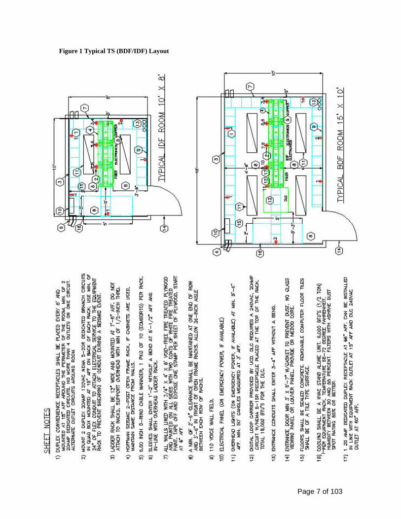
• See Figure 1 for recommended TS Layout
• Lighting shall not receive power from the same electrical distribution panel breaker as the telecommunications equipment in the TS.
• Door shall be fire rated to match the fire rating of the wall in which it is installed as
required by local code requirements. If required, double door 6-feet wide by 7-feet, 5-inches high without a doorsill and center post is recommended. TS doors that open to an outside environment shall be rated for exterior use and shall have a weatherproof gasket to prevent vermin, water, dirt and dust from entering the room. A positive pressure type of HVAC system shall be installed in this type of TS.
• Floor loading capacity in the ER (ADF/BDF) shall be designed for a minimum
distributed load rating of 100 lb/ft² and a minimum concentrated load rating of at least 2000 lb/ft². The floor loading for a TR (IDF) shall be designed for a minimum load rating of 50 lb/ft². If a raised floor system is used, then it is possible the space will have to comply with the requirements of Article 645 Information Technology Equipment of the 2001 California Electrical Code and NFPA 75 Standard for the Protection Information Technology Equipment, 2003 Edition.
• Ceilings are to be open to the underside of the floor above and have a minimum clearance of 9-feet.
• See Figures 1 for equipment and cross-connect field clearances in the Telecommunications Spaces:
• A standalone HVAC unit shall be provided for the telecommunications space.
The filters in the HVAC system should have an ASHRAE dust spot rating of 85% or better.
Page 7 of 103
Figure 1 Typical TS (BDF/IDF) Layout

Page 8 of 103
NOTE: The type and location of the cross-connect fields may influence the optimal placement of pathways. Note: In many cases, equipment and termination hardware may extend beyond racks and backboards. It is important to note that the clearance is measured from the outermost surface of these devices, rather than from the mounting surface of the rack or backboard.
Telecommunications Space (TS) Fire Safety and Protection Requirements
• Portable fire extinguishers shall be provided and maintained within 75-feet or less travel distance from any part of the occupied space within the TS per campus requirements. The size of the fire extinguisher shall be a minimum 2-A, 10-B, C rating.
• Drainage troughs shall be placed under the sprinkler pipes to prevent leakage onto the
electronic equipment within the room. Drain troughs shall be provided with a drain that will route the water outside of the TS. Alternate fire-suppression systems should be considered in these areas.
• If an access raised-floor system is to be installed in any TS and a fire detection system is
required under the floor, the system shall be a cross-zone detection system. In addition, placement of the detector may affect the way cables are routed under a raised floor. If ionization detectors are installed, there is a potential problem with the accumulation of dust under the floor. It is possible during the performance of cable work under the floor that dust could set off the detectors. Provisions shall be made in the fire detection system design to reduce the possibly of false alarms and activation of a fire suppression system.
Telecommunications Space (TS) Electrical Requirements
• A sub-panel or at a minimum, ALL TS’s shall be provided dedicated electrical service in all ADF/BDF/IDF (ER/TR) rooms. The estimated electrical load for the telecommunications space shall not exceed 80% of the panel.
• Dedicated power circuits from shared panel boards shall be provided with both transient
voltage surge suppression and electrical high frequency noise filtering.
• If a low number of telecommunications spaces are planned, one electrical panel may serve multiple telecommunications spaces as a design alternative.
• Sub-panels shall be located to conserve wall space and should be connected to an
emergency power source if available to the building. Emergency power is especially important in the TS’s that house Digital Loop Carrier systems to ensure voice and emergency systems remain operational during power outages that may extend past the systems battery backup capability.
• HVAC systems shall not use the same electrical panel that is used to support
telecommunications spaces.

Page 9 of 103
Equipment Rack and Cabinet Electrical Requirements
• Reference Division 27 11 16, Communications Cabinets, Racks and Enclosures, Figure 24-28.
• Reference Division 27 11 16, Communications Cabinets, Racks and Enclosures, Figure
24-28. • Special considerations:
o ADF equipment racks and cabinets shall have 30 Amp, 120V AC NEMA 5-30R-
spade receptacles in place of the 20 Amp, 120V AC NEMA 5-20R-spade receptacles. o Provide a duplex 20 Amp, 240V NEMA 6-15R receptacle for a DLC cabinet.
Building Design Requirements Work Area Outlets (WAO) A power receptacle should be installed near each WAO location (i.e. within 3-feet). WAO locations are typically at the same height as the power receptacles. WAO locations shall be coordinated with the furniture layout. WAO density: 1. A minimum of one WAO location containing one Voice and Data jack or Network Access
Module (NAM) shall be installed per work area.
2. For building areas where it is difficult to add additional WAO’s at a later date (i.e. private office space), a minimum of two separate WAO locations shall be provided in the initial design for that area, and they shall be located to offer maximum flexibility for change within the work area, (i.e. on opposing walls in private office space).
3. A minimum of one WAO with a minimum of two Voice NAM’s and a Data NAM shall be installed at the Fire Alarm Control Panel (FACP).
4. A minimum of one WAO with one Voice NAM shall be installed for each elevator bay (incl. wheel chair elevator) in the Elevator Control Room within the control panel.
5. A minimum of one WAO of one Voice or Data NAM shall be installed within the Building Environmental Control Panel.
6. A minimum of one WAO of two Data NAMs shall be planned for any Building Access Systems (card and palm readers) that may be installed in the building.
7. Open office area interior design, telecommunications distribution planning, and power system distribution planning should be coordinated to avoid conflicting assignments for pathways or WAO locations, installation sequencing problems, and other difficulties.
Page 10 of 103
Courtesy, Pay, Text, Emergency and Wheel Chair Elevator Telephones In order to comply with the American Disabilities Act (ADA) Accessibility Guidelines: 1. The mounting height of the device box for Wall Mounted Telephones shall be 40-inches
Above the Finished Floor (AFF). Wall-mounted telephones shall not be installed above a counter top.
2. The mounting height of the device box for a wheelchair accessible telephone (to include payphones and wheel chair elevator phones) shall be 40-inches AFF.
3. If a Text Telephone is required, it shall not be mounted to the wheelchair accessible telephone position. The text telephone unit shall require a power receptacle at 18” AFF under the Text Telephone.
Slab on Grade
• If a slab on grade approach is planned for the first floor of newly constructed buildings, then special attention shall be provided to potential communication WAO’s that may be installed in the floor. The following minimum requirements: o Supporting conduits shall run beneath the slab and shall be PVC schedule 40 or
better. o At no time shall the conduit run below the membrane barrier or be placed directly in
the soil. o Conduits shall not contain more than two 90-degree bends and exceed more than
100-feet in length between pulling points.
Tenant Improvement Project
• Abandoned cables, not identified and labeled for future use, increase the fire fuel load
and shall be removed in accordance with the 2002 National Electrical Code.
• CR shall be contacted and requested to survey the existing cable plant. There is a possibility that all or a portion of the existing installed cable may be reused.
Site Work Project Drawings
• Project drawings shall include the following site construction information:
o Details of typical trench cross sections showing conduit locations in the trench, clearances from final grade, backfill materials and depths, pavement cutting information, and compacting requirements for both paved and unpaved areas.
o Construction notes applicable to the work being performed. o A scale drawing showing location ties to existing structures, cable, conduit,
MH/PB’s, and any conflicting substructures. Profile drawings of congested areas where vertical and horizontal separation from other utilities is critical during cutting and placing operations.
Page 11 of 103
o A legend explaining industry standard drawing symbols of all relevant structures and work operations.
o Conduit types, dimensions, and wall-to-wall measurements when used with MH/ PB, pedestals and Equipment and Telecommunications Rooms (ER/TR’s).
Common Work Results For Communications 27 05 00 Site construction includes support structures such as aboveground and underground conduit systems, maintenance holes (MH), pull boxes (PB) and pole lines. Work performed in this segment shall be designed and installed per the California Electrical Code (CEC). Also reference the National Electrical Safety Code (NESC), California PUC General Orders 95 and 128 and the TIA-758-A Specifications for Outside Plant Construction.
Cable Distribution Methods Communications Resources Engineering and Construction Management (ECM) office shall be contacted to determine the best cable distribution method along the proposed cable route. The distribution may be one or a combination of underground, direct-buried, directional boring or aerial methods. Grounding and Bonding for Communications Systems 27 05 26 The following information is intended to act as a guide to assist the designer in planning, designing and installation of a technically sound grounding and bonding solution for Telecommunication Spaces. The following specifications are to be adhered to:
• ANSI J/STD-607-A, Commercial Building Grounding and Bonding Requirements for Telecommunications, National Electrical Code (NEC)
• BICSI guidelines • ANSI-J-STD-607-A Commercial Building Grounding (Earthing) and Bonding
Requirements for Telecommunications • ANSI/TIA/EIA-606-A Administration Standards for the Telecommunications
Infrastructure of Commercial Buildings. • California Electrical Code Article 250 and references therein. • California Electrical Code Article 800.
In the event of conflicting requirements, California Electrical Code requirements shall prevail. Compliance with the National Electrical Code (NEC) and local codes mandated by the authority having jurisdiction (AHJ) is essential for the proper application of this Manual. If the designer finds a conflict between a local safety code, BICSI guidelines and the manufacturer’s requirements, the conflict should be resolved with the authority having jurisdiction (AHJ) before proceeding.

Page 12 of 103
Telecommunications Bonding Infrastructure. In addition to the normal electrical ground system, a Main Telecommunications Ground Busbar (MTGB) and a Telecommunications Ground Busbar (TGB) system are required per ANSI/EIA/TIA-STD-J-607-A. These grounding systems shall be installed to support the telecommunications infrastructure.
• A TMGB shall be located in the ER (ADF/BDF) and is to be bonded to the nearest approved building grounding electrode (e.g., structural steel or ground rod) and.the equipment grounding system (ac branch circuit panel board’s equipment grounding busbar) by conventional welds, exothermic welds, clamp-and-braze method or UL approved compression type connectors where practical. Exothermic welds are the preferred method.
• In each TR (IDF), a TGB shall be installed. The TGB shall be bonded to the electrical
panel serving the area where the TGB is installed, bonded to building steel, whether it is a horizontal or vertical beam, and bonded in series to the main TMGB. The ac grounding panel board, known as a branch circuit panel board, may reside in the ER.
• In a renovation or remodeling project where a suitable ground to the electrical service ground is not available, a grounding electrode shall be installed in accordance with the CEC Section 250-70.
• Bonding conductors shall be installed with the shortest length and routed with minimum
bends or changes in direction.
• Bonding conductors shall be green or marked with a distinctive green color and labeled. If the TBB is insulated, the insulation shall meet the fire ratings of its pathway.
• A grounding equalizer (GE) is not required.
• The sizing of the TBB is not intended to account for the reduction or control of
electromagnetic interference. The TBB should be calculated for a size that conforms to the guidelines set by the NEC. Reference Table 1 Sizing of TBB.
Table 1 Sizing of TBB.
Sizing of the TBB TBB length linear m (ft) TBB Size (AWG)
less than 4 (13) 6 4 – 6 (14 – 20) 4 6 – 8 (21 – 26) 3
8 – 10 (27 – 33) 2 10 – 13 (34 – 41) 1 13 – 16 (42 – 52) 1/0 16 – 20 (53 – 66) 2/0
greater than 20 (66) 3/0
Page 13 of 103
Bonding Connections
• Bonding connections shall be made directly to the points being bonded, avoiding unnecessary connections or splices.
• All grounding and bonding connectors shall be listed by a nationally recognized testing laboratory (NRTL) as required by the NEC.
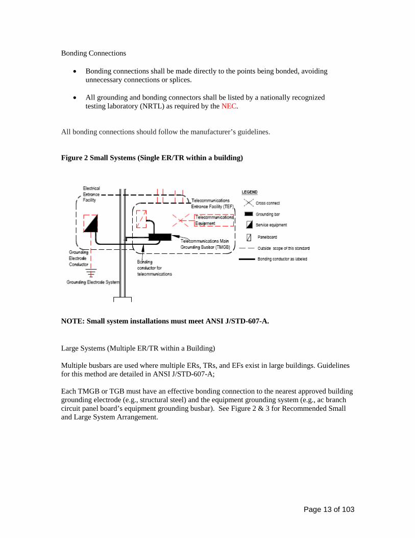
All bonding connections should follow the manufacturer’s guidelines. Figure 2 Small Systems (Single ER/TR within a building)
NOTE: Small system installations must meet ANSI J/STD-607-A. Large Systems (Multiple ER/TR within a Building) Multiple busbars are used where multiple ERs, TRs, and EFs exist in large buildings. Guidelines for this method are detailed in ANSI J/STD-607-A; Each TMGB or TGB must have an effective bonding connection to the nearest approved building grounding electrode (e.g., structural steel) and the equipment grounding system (e.g., ac branch circuit panel board’s equipment grounding busbar). See Figure 2 & 3 for Recommended Small and Large System Arrangement.

Page 14 of 103
Figure 3 Recommended Large System Arrangement (Multiple ER/TR within a Building)
Telecommunications Main Grounding Busbar (TMGB) & Telecommunications Grounding Busbar (TGB)
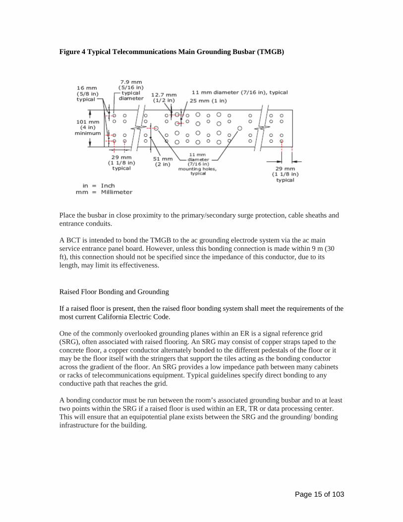
• The TMGB & TGB must be a predrilled copper busbar with holes for use with standard-sized lugs, have minimum dimensions of 6.3 mm (0.25 in) thick by 101 mm (4 in) wide and be minimum 20” (see Figure 4).
Page 15 of 103
Figure 4 Typical Telecommunications Main Grounding Busbar (TMGB)
Place the busbar in close proximity to the primary/secondary surge protection, cable sheaths and entrance conduits. A BCT is intended to bond the TMGB to the ac grounding electrode system via the ac main service entrance panel board. However, unless this bonding connection is made within 9 m (30 ft), this connection should not be specified since the impedance of this conductor, due to its length, may limit its effectiveness. Raised Floor Bonding and Grounding If a raised floor is present, then the raised floor bonding system shall meet the requirements of the most current California Electric Code. One of the commonly overlooked grounding planes within an ER is a signal reference grid (SRG), often associated with raised flooring. An SRG may consist of copper straps taped to the concrete floor, a copper conductor alternately bonded to the different pedestals of the floor or it may be the floor itself with the stringers that support the tiles acting as the bonding conductor across the gradient of the floor. An SRG provides a low impedance path between many cabinets or racks of telecommunications equipment. Typical guidelines specify direct bonding to any conductive path that reaches the grid. A bonding conductor must be run between the room’s associated grounding busbar and to at least two points within the SRG if a raised floor is used within an ER, TR or data processing center. This will ensure that an equipotential plane exists between the SRG and the grounding/ bonding infrastructure for the building.

Page 16 of 103
IMPORTANT: IG systems are not recommended for voice and data equipment, regardless of intent. Though such an equipment grounding system is permitted by the NEC® (e.g., provided it meets stringent wiring requirements), the use of such a system defeats the purpose of an equipotential plane. Labeling All ground attachments shall be properly tagged and labeled in accordance with TIA/EIA-606-A.
Testing The Telecommunications Ground & Bonding System shall be tested with an Earth Ground Resistance Tester used in the Two Point Test Method.
• All testing should be done with the entire building in operation.
• Test using the two point test mode. If the ohmic value is less than 0.1 Ohm between the
two test points the bonding is adequate.
• The installer / technician conducting these tests must be certified level VI by UIC ACCC TED.
These tests shall be recorded on sheets provided for this purpose by UC Davis Pathways for Communications Systems 27 05 28 Communication Pathways Cable Support (General) The main routing and support systems for communication cables on the UC Davis campus are:
• Cable tray system (hallways) • J-hooks and adjustable cable support (bags) (accessible false ceiling areas) • Conduit home runs (hard ceiling areas, inaccessible ceiling areas, in-floor boxes,
masonry walls)The CR standard for a combined system is an overhead distribution method based on the use of a cable tray and J-hook system for routing and an EMT conduit stub-up to the WAO device boxes.
All cable trays and J-hooks shall be dedicated for CR use only. No other building cabling system (800 MHz radio, access control, building automation, etc) is to be installed within the cable tray and J-hooks. Separate cable support shall be supplied.

Page 17 of 103
Hangers and Supports for Communications Systems 27 05 28.29 Communications J-Hooks
• J-hooks shall be spaced at a maximum of 48-inches in the main bundle, 48 to 60-inches apart in the secondary bundles and within 6-inches of an EMT conduit stub-up.
• Main cable bundle will be made up of 4-inch saddle bags and supported on a minimum of
3/8” threaded rod. Ceiling wires or pencil rod is acceptable for secondary cable bundles. Cable supports shall not exceed 40% fill ratio. Refer to manufacturer’s recommendations.
• Location of J-hooks shall be indicated on the Electrical Design and/or
Telecommunications drawings.
• Cables shall not be secured to the J-hook with cable ties or vinyl tape. Conduits and Backboxes for Communications Systems 27 05 28.33 Installed interior conduits shall:
• Be installed in the most direct and accessible route possible (parallel to building lines and located in and above accessible hallways).
• Contain no more than two 90-degree bends in any dimensional plane or exceed 100-feet
in length between pulling points or interior pull boxes. A pull box is not to be used in place of a conduit sweep. See table 2.
• Stub up to an accessible ceiling area and within 6-inches of a J-hook or cable tray from a
device box. • Be reamed at both ends and have a plastic bushing installed on each end to prevent
damage during cable installation.
• Have a pull string (also called a pull cord) installed in all conduits with a minimum test rating of 200 lb.
• Be installed through areas in which flammable materials may be stored or over and
adjacent to boilers, incinerators hot water lines or steam lines. Table 2 Conduit Bend Radiuses
Internal Diameter Minimum Bend Radius 2 inches or less 6 times the internal conduit diameter 2 1/4 inches or more 10 times the internal conduit diameter
Page 18 of 103
• All conduits shall be bonded and grounded in accordance with the CEC and ANSI-J-STD-607-A, where applicable.
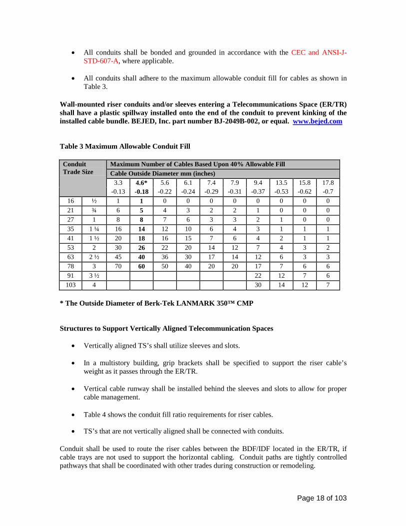
• All conduits shall adhere to the maximum allowable conduit fill for cables as shown in
Table 3.
Wall-mounted riser conduits and/or sleeves entering a Telecommunications Space (ER/TR) shall have a plastic spillway installed onto the end of the conduit to prevent kinking of the installed cable bundle. BEJED, Inc. part number BJ-2049B-002, or equal. www.bejed.com
Table 3 Maximum Allowable Conduit Fill Conduit Trade Size
Maximum Number of Cables Based Upon 40% Allowable Fill Cable Outside Diameter mm (inches)
3.3 4.6* 5.6 6.1 7.4 7.9 9.4 13.5 15.8 17.8 -0.13 -0.18 -0.22 -0.24 -0.29 -0.31 -0.37 -0.53 -0.62 -0.7
16 ½ 1 1 0 0 0 0 0 0 0 0 21 ¾ 6 5 4 3 2 2 1 0 0 0 27 1 8 8 7 6 3 3 2 1 0 0 35 1 ¼ 16 14 12 10 6 4 3 1 1 1 41 1 ½ 20 18 16 15 7 6 4 2 1 1 53 2 30 26 22 20 14 12 7 4 3 2 63 2 ½ 45 40 36 30 17 14 12 6 3 3 78 3 70 60 50 40 20 20 17 7 6 6 91 3 ½ 22 12 7 6
103 4 30 14 12 7 * The Outside Diameter of Berk-Tek LANMARK 350™ CMP Structures to Support Vertically Aligned Telecommunication Spaces
• Vertically aligned TS’s shall utilize sleeves and slots.
• In a multistory building, grip brackets shall be specified to support the riser cable’s weight as it passes through the ER/TR.
• Vertical cable runway shall be installed behind the sleeves and slots to allow for proper
cable management.
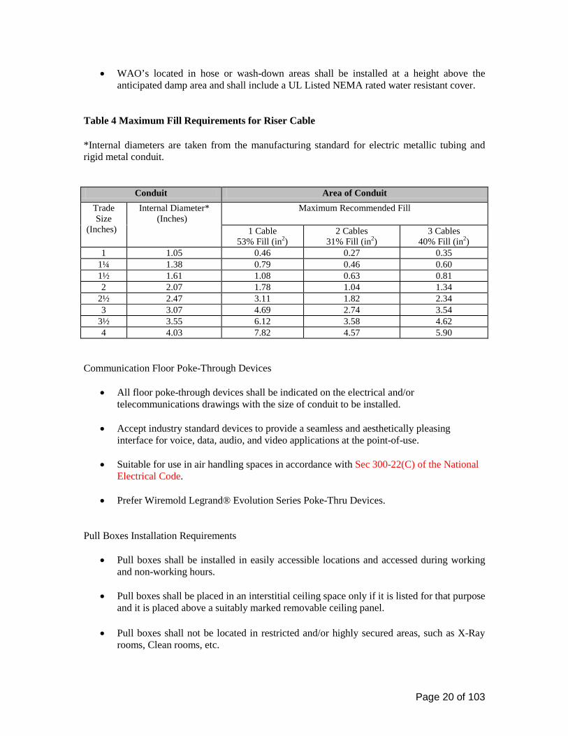
• Table 4 shows the conduit fill ratio requirements for riser cables.
• TS’s that are not vertically aligned shall be connected with conduits. Conduit shall be used to route the riser cables between the BDF/IDF located in the ER/TR, if cable trays are not used to support the horizontal cabling. Conduit paths are tightly controlled pathways that shall be coordinated with other trades during construction or remodeling.
Page 19 of 103
• Each 4-inch conduit shall be installed with a mule tape and contain a bushing with a ground on each end to ground and protect the cable.
• Conduits that enter the ER/TR shall be placed near the corner and as close as possible to
the wall where the backboard is mounted to allow for proper cable racking and to minimize the cable route inside the ER/TR.
• Conduit located in the ceiling shall protrude into the ER/TR 1 to 2 inches and a minimum 7½ feet above the finished floor. Conduit shall not turn down.
• Provide a conduit riser diagram in the contract drawings. Reference Table 4 for details on conduit fill for riser cables.
Note: A 4-inch conduit shall be dedicated from the ER/TR to a sealed junction box on the roof of the building for the installation of an 800 MHz antenna cable. This conduit shall be grounded using a path other than the telecommunications ground provided in the ER/TR. Work Area Outlet (WAO) Conduit and Backbox Size Requirements
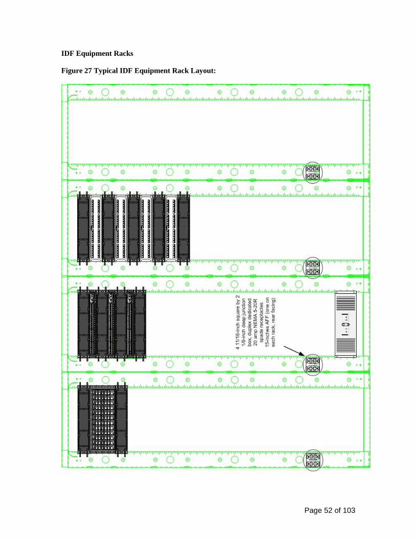
• All WAO’s shall have a minimum of one (1) 1-1/4 inch trade size Electrical Metallic Tubing (EMT) conduit installed from the device box to readily accessible ceiling space within 6-inches of an installed J-hook or cable tray. WAO’s shall have a standard 4-11/16-inch square by 2-1/8-inch deep device box with a single gang mud ring installed flush mounted within the wall, unless otherwise noted.
• All Fiber to the Desktop FTTD WAO’s shall have an additional 1-1/2-inch device box
extension installed in the front of the standard 4-11/16-inch square by 2-1/8-inch deep device box. This extension is required to deepen the device box and maintain the fiber optic bend radius. A dual gang mud ring shall be installed on the front to accommodate an 8-port faceplate if voice, data and/or video NAM’s are planned for the same location.
• Wall-mounted courtesy and public pay telephones device box shall be mounted at +42-
inches AFF for a wall-mounted telephone. An electrical outlet will be provided at +18-inches to accommodate a TTY phone.
• Floor-mounted WAO’s shall have a minimum of one (1) 1-1/4 inch trade size Electrical
Metallic Tubing (EMT) conduit installed from the device box to readily accessible ceiling space within 6-inches of an installed J-hook or cable tray. A minimum of (1) one EMT conduit shall service each individual floor box. Floor boxes shall not
be looped or daisy-chained together with one single conduit, regardless of the size of conduit.
• The maximum allowable conduit fill requirements shown in Table 3 shall be adhered to when designing conduit installations for WAO device box and Wiremold® locations.
• Interior conduits and/or sleeves shall be properly sized in accordance with TIA/EIA 569-
B, Table 3.
• Typical mounting height shall be +18-inches AFF or match the height of new and existing power receptacles, where appropriate.
Page 20 of 103
• WAO’s located in hose or wash-down areas shall be installed at a height above the anticipated damp area and shall include a UL Listed NEMA rated water resistant cover.
Table 4 Maximum Fill Requirements for Riser Cable
*Internal diameters are taken from the manufacturing standard for electric metallic tubing and rigid metal conduit.
Conduit Area of Conduit Trade Size
(Inches)
Internal Diameter* (Inches)
Maximum Recommended Fill
1 Cable 53% Fill (in2)
2 Cables 31% Fill (in2)
3 Cables 40% Fill (in2)
1 1.05 0.46 0.27 0.35 1¼ 1.38 0.79 0.46 0.60 1½ 1.61 1.08 0.63 0.81 2 2.07 1.78 1.04 1.34
2½ 2.47 3.11 1.82 2.34 3 3.07 4.69 2.74 3.54
3½ 3.55 6.12 3.58 4.62 4 4.03 7.82 4.57 5.90
Communication Floor Poke-Through Devices
• All floor poke-through devices shall be indicated on the electrical and/or telecommunications drawings with the size of conduit to be installed.
• Accept industry standard devices to provide a seamless and aesthetically pleasing
interface for voice, data, audio, and video applications at the point-of-use.
• Suitable for use in air handling spaces in accordance with Sec 300-22(C) of the National Electrical Code.
• Prefer Wiremold Legrand® Evolution Series Poke-Thru Devices. Pull Boxes Installation Requirements
• Pull boxes shall be installed in easily accessible locations and accessed during working and non-working hours.
• Pull boxes shall be placed in an interstitial ceiling space only if it is listed for that purpose
and it is placed above a suitably marked removable ceiling panel.
• Pull boxes shall not be located in restricted and/or highly secured areas, such as X-Ray rooms, Clean rooms, etc.
Page 21 of 103
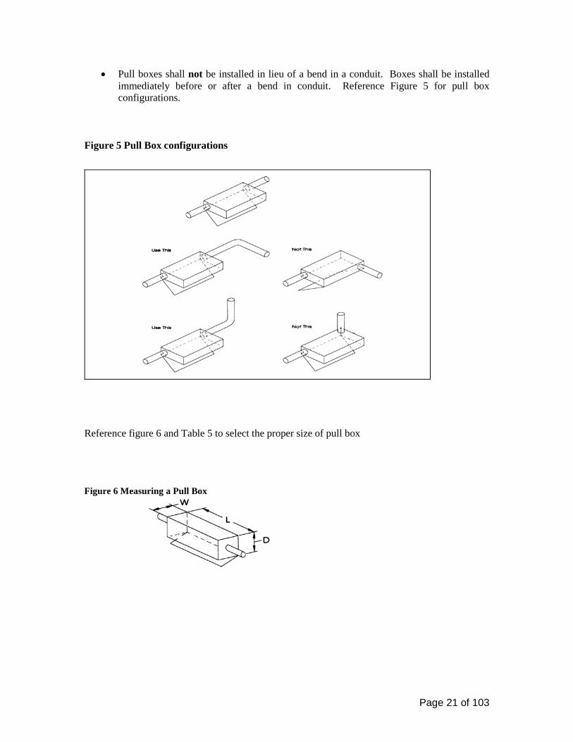
• Pull boxes shall not be installed in lieu of a bend in a conduit. Boxes shall be installed immediately before or after a bend in conduit. Reference Figure 5 for pull box configurations.
Figure 5 Pull Box configurations
Reference figure 6 and Table 5 to select the proper size of pull box Figure 6 Measuring a Pull Box

Page 22 of 103
Table 5 Sizing a Pull Box Maximum Trade Size of Conduit (Inches)
For Each Additional Conduit Increase Width (Inches) Size of Box
Width Length Depth 0.75 4 12 3 2
1 4 16 3 2 1.25 6 20 3 3 1.5 8 27 4 4 2 8 36 4 5
2.5 10 42 5 6 3 12 48 5 6
3.5 12 54 6 6 4 15 60 8 8
Cable Trays for Communications Systems 27 05 28.36 Communications Cable Runway and Trays Cable Runway
• Cable runway shall be used only in Telecommunications Spaces (TS).
• Cable runway shall be secured on 5-foot centers using an angled wall support and standard trapeze type support system in accordance with manufacturer specifications and applicable California Building and Electrical (CBC, CEC) Codes.
• Cable runway shall be aluminum or steel type. All cable runways shall be a minimum
12-inches wide with 9-inch rung spacing.
• Cable runway shall not be placed within 5-inches of any overhead light fixture and within 12-inches of any electrical ballast. A minimum clearance of 12-inches above the cable ladder shall be maintained at all times. All bends and T-joints in the cable ladder shall be fully accessible from above (within one foot).
• Cable runway shall meet the requirements in TIA/EIA 569-B and applicable addendums,
to include the latest Addendum 7, Cable Trays and Wire ways, dated December 2001.
• Cable runway shall be grounded and bonded in accordance with ANSI/TIA/EIA-J-STD-607-A. All splices, T-Sections and bends shall be bonded together. Cable runway and trays shall not
be used as an equipment ground nor seismic support or bracing.
• Cable runway shall meet Zone 4 or higher seismic bracing standards.

Page 23 of 103
Cable Trays
• The use of steel wire basket tray system is the preferred method of cable tray systems within the corridors. Plenum mesh type trays shall be used in plenum ceiling areas. All cable trays shall be a minimum of 12-inches wide and 2-inches deep. Deep aluminum type cable trays shall not be used due to ceiling space and accessibility limitations.
• Cable trays that are used to support horizontal cabling may be used to support riser cables provided the cable trays carrying capacity can accommodate the riser cables
• Cable trays shall be secured on 10-foot centers using an angled wall support or a standard
trapeze type 1/2-inch threaded rod support system in accordance with manufacturer specifications and applicable California Building and Electrical codes. Single center-mounted steel supporting rod and bottom “T” connector style of support shall not be used.
• Cable trays shall be steel wire basket or mesh suitable for hallways and false ceiling
areas.
• Cable trays shall be sized to accommodate future Fiber to the Desktop installations and building growth.
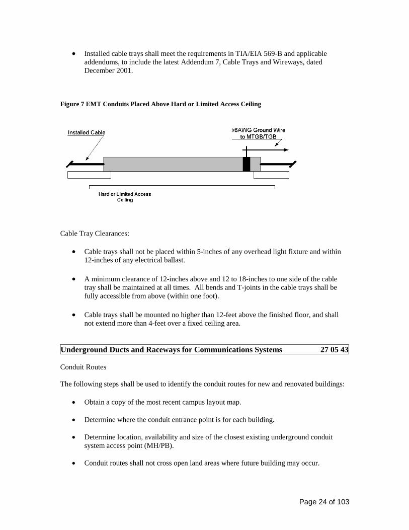
• Cable trays shall be installed in accessible ceiling areas only and shall transition to a
minimum of three 4-inch EMT conduits when routed over fixed, hard and inaccessible ceiling spaces. Reference Figure 7.
• All cable trays shall have seismic bracing as designed by a California licensed structural engineer. Cable trays shall meet Zone 4 or higher seismic bracing standards.
• Cable trays shall extend 6-inches into the TS (ER/TR) then utilize a manufacturer’s
radius drop out (waterfall) to protect station cables from potential damage from the end of the tray. Where conduits used in place of tray provide plastic spillways installed onto the end of the conduit to prevent kinking of the installed cable bundle. BEJED, Inc. part number BJ-2049B-002, or equal. www.bejed.com
• Cable trays shall be grounded and bonded in accordance with ANSI/TIA/EIA-J-STD-
607-A. All splices, T-Sections and bends shall be bonded together. Cable trays shall not be used as an equipment ground nor seismic support or bracing.
• All cable tray penetrations through firewalls shall allow cable installers to firestop around
the cables after they are installed. Tray-based mechanical firestop systems shall be used when a cable tray penetrates a fire barrier. All firestopping installations shall be labeled in accordance with ANSI/TIA/EIA 606-A.
• Cables installed in cable trays shall not contain, nor be fastened with velcro, tape or
plastic type cable ties (tie-wraps).
Page 24 of 103
• Installed cable trays shall meet the requirements in TIA/EIA 569-B and applicable addendums, to include the latest Addendum 7, Cable Trays and Wireways, dated December 2001.
Figure 7 EMT Conduits Placed Above Hard or Limited Access Ceiling
Cable Tray Clearances:
• Cable trays shall not be placed within 5-inches of any overhead light fixture and within 12-inches of any electrical ballast.
• A minimum clearance of 12-inches above and 12 to 18-inches to one side of the cable
tray shall be maintained at all times. All bends and T-joints in the cable trays shall be fully accessible from above (within one foot).
• Cable trays shall be mounted no higher than 12-feet above the finished floor, and shall
not extend more than 4-feet over a fixed ceiling area.
Underground Ducts and Raceways for Communications Systems 27 05 43 Conduit Routes The following steps shall be used to identify the conduit routes for new and renovated buildings:
• Obtain a copy of the most recent campus layout map.
• Determine where the conduit entrance point is for each building.
• Determine location, availability and size of the closest existing underground conduit system access point (MH/PB).
• Conduit routes shall not cross open land areas where future building may occur.

Page 25 of 103
• All branch conduits exiting a MH/PB shall be designed as Subsidiary conduits only (exit from the end wall of the MH/PB, not from the side wall). Lateral conduits entering/exiting MH/PB’s are not allowed.
Underground Conduit Construction General
• Conduit shall be Polyvinyl-Chloride (PVC) Schedule 40 or 80 (dependent upon concrete encasement requirements), corrosion-resistant plastic with a 4-inch inside diameter for underground installations and Galvanized Rigid Steel (GRS) or PVC Externally Coated GRS for riser applications.
• Spacers shall be used in the trench to support the conduits.
• A solid core #10 AWG copper wire shall be installed externally along any conduit run for the purpose of locating and tracing the conduit route.
• Fabric multi-cell type of innerduct shall be considered for conduits planned for fiber optic
cable installations. • All installed conduits shall be cleaned and verified with a flexible mandrel and a stiff
brush. Mandrels shall be 12-inches in length and sized to within ¼-inch of the inside diameter of the conduit.
• All conduits shall be provided with mule tape with a minimum of 200 pound pulling
tension. • All unused entrance conduits shall be capped/plugged with expandable type duct plugs
(i.e. Jackmoon) inside the building to prevent rodents, water or gases from entering the building.
• Conduit stubs entering the building shall extend beyond the foundation and landscaping
to prevent shearing of the conduit and allow for access. Conduit entering from a below grade point shall extend 4-inches above the finished floor in the ER/TR. Conduit entering from ceiling height shall terminate 4 inches below the finished ceiling.
• All future conduit stubs shall be flagged for easy identification and a 3M® electronic ball
marker shall be placed. • All metallic conduit and sleeves shall be reamed, bushed and capped when placed. • The minimum depth of a trench shall allow for 24-inches of cover from the top of the
conduit/cable to final grade. Warning tape containing metallic tracings shall be placed a minimum of 18-inches above the underground conduit/duct structure and direct-buried cable to minimize any chance of an accidental dig-up. Both ends of the metallic warning tape shall be accessible after installation.
Page 26 of 103
• There shall not be more than the equivalent of two (2) 90-degree bends (180-degrees total) between pull points, including offsets and kicks. Back-to-back 90-degree bends shall be avoided. All bends shall be manufactured long sweeping bends with a radius not less than 6 times the internal diameter of conduits 2-inches or smaller or 10 times the internal diameter of conduits larger than 2-inches. Bends made manually shall not reduce the internal diameter of the conduit.
• A university representative will observe and inspect utilities trenching, excavation, backfilling and compaction as appropriate. Contractor shall appropriately schedule all inspections prior to commencing trenching and backfilling operations. All installations are subject to satisfactory inspection by the University’s representative.
• Contractor shall submit a USA ticket to locate and mark all subsurface utilities, such as power, communications, gas, water, outdoor lighting, etc. 48 hours (or in accordance with statutes regulating utilities) prior to any excavation on campus. An Underground Service Alert (USA) call number receipt (ticket) shall be present and on-site and all utilities located and marked before any construction work involving excavation begins.
• Conduits shall be secured with rebar, or equal when covering conduits with concrete.
• Conduit shall be encased in concrete or cement slurry when the following conditions exist:
o Minimum conduit depth cannot be attained. o Conduits pass under sidewalks, roadways, driveways, railroad tracks and at bend
points. o All conduit bends and sweeps shall be concrete encased to prevent movement and
“burn-through” by the pull rope during cable installations. o Concrete encasement shall comply with State of California, Department of
Transportation standard specifications. o An orange colored additive shall be raked or trowel-worked into the wet concrete or
cement slurry to identify the duct structure as communications. o Reinforcing bars within the concrete shall be used at any location subject to extreme
stress. o CR shall inspect and approve all conduits prior to encasement.
Note: The American Public Works Association has adopted the color orange for the telecommunications cables. Directional Boring
• Directional Boring (Horizontal Directional Drilling - HDD) is a trenchless method of installing underground pipes & conduits with minimal surface disruption.
• High-density polyethylene (HDPE) conduit to be used for directional boring.
• A swivel will be used at all times to prevent rotation of the product pipe.
Page 27 of 103
Sizing Underground Conduit
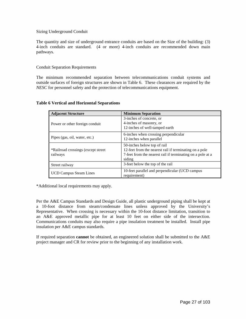
The quantity and size of underground entrance conduits are based on the Size of the building: (3) 4-inch conduits are standard. (4 or more) 4-inch conduits are recommended down main pathways. Conduit Separation Requirements The minimum recommended separation between telecommunications conduit systems and outside surfaces of foreign structures are shown in Table 6. These clearances are required by the NESC for personnel safety and the protection of telecommunications equipment. Table 6 Vertical and Horizontal Separations
Adjacent Structure Minimum Separation
Power or other foreign conduit 3-inches of concrete, or 4-inches of masonry, or 12-inches of well-tamped earth
Pipes (gas, oil, water, etc.) 6-inches when crossing perpendicular 12-inches when parallel
*Railroad crossings (except street railways
50-inches below top of rail 12-feet from the nearest rail if terminating on a pole 7-feet from the nearest rail if terminating on a pole at a siding
Street railway 3-feet below the top of the rail
UCD Campus Steam Lines 10-feet parallel and perpendicular (UCD campus requirement)
*Additional local requirements may apply. Per the A&E Campus Standards and Design Guide, all plastic underground piping shall be kept at a 10-foot distance from steam/condensate lines unless approved by the University’s Representative. When crossing is necessary within the 10-foot distance limitation, transition to an A&E approved metallic pipe for at least 10 feet on either side of the intersection. Communications conduits may also require a pipe insulation treatment be installed. Install pipe insulation per A&E campus standards. If required separation cannot be obtained, an engineered solution shall be submitted to the A&E project manager and CR for review prior to the beginning of any installation work.
Page 28 of 103
Maintenance Holes (MH) and Pull Boxes (PB) General Requirements
• MH/PB’s are required where maximum cable reel lengths are exceeded, at the intersection of main and branch conduit runs and at other locations where access to the cable in a conduit system is required.
• The maximum distance allowed between buildings and MH/PB’s or between two
MH/PBs’ is 600 feet.
• No more than (2) 90 degree bends between MH/PBs’.
• MH’s and PB’s shall be constructed to withstand a minimum of ASSHTO-H20-44 full traffic loading.
• All MH/PB covers shall be rated for heavy and/or constant vehicular traffic, regardless of
placement location.
• All hardware in MH/PB’s shall be galvanized.
• Pulling eyes shall be a minimum of 7/8-inches in diameter and located at opposite ends of each conduit entrance point.
• All MH/PB covers shall be marked for easy identification (Communications) and have a permanently attached label indicating the assigned MH/PB number. (Contact CR Project Engineer for MH/PB number.
• MH locations where the distance between the ceiling of the manhole and the street level
exceeds 24-inches shall require the installation of permanent steps in the neck of the MH. These steps shall be installed in the neck rings at the same time as the MH is being installed, per manufacturer instructions. Steps shall not be cut and cemented in place after the installation of the neck ring.
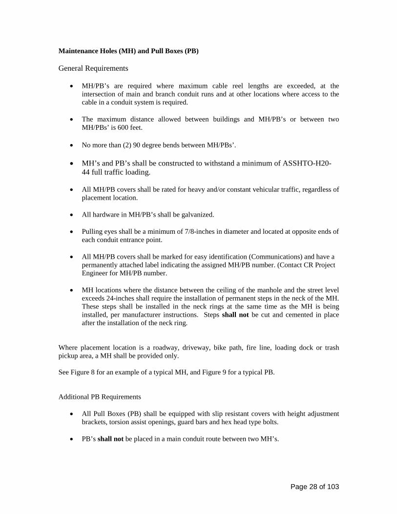
Where placement location is a roadway, driveway, bike path, fire line, loading dock or trash pickup area, a MH shall be provided only. See Figure 8 for an example of a typical MH, and Figure 9 for a typical PB. Additional PB Requirements
• All Pull Boxes (PB) shall be equipped with slip resistant covers with height adjustment brackets, torsion assist openings, guard bars and hex head type bolts.
• PB’s shall not be placed in a main conduit route between two MH’s.

Page 29 of 103
• MH/PB’s shall be placed at strategic locations in a conduit system to allow installers to pull cable through the conduit with minimum difficulty and to protect the cable from excessive tension.
Figure 8 Typical Maintenance Hole
Page 30 of 103
Figure 9 Typical Pull Box

Page 31 of 103
MH/PB Conduit Entry Requirements:
• If the total number of conduits being placed is significantly less than the capacity of the
termination MH or cable entrance, conduit should enter at the lower level. The upper space shall be reserved for future additions.
• Conduit servicing buildings or other MH/PB’s shall be installed using the subsidiary
conduit method. Lateral conduits entering/exiting MH/PB’s are not allowed.
• 45-degree conduit angles are preferred. Regardless of depth, all bends and sweeps shall be concrete encased to prevent movement and “burning through” by the pull rope during cable installations.
• Conduits installed between MH/PB’s and buildings and between other MH/PB’s shall be
sloped per TIA 758-A to ensure proper drainage of water.
• All conduits entering buildings shall be plugged with expandable type duct plugs (i.e. Jackmoon) inside the building to prevent rodents, water or gases from entering the building. MH/PB conduits shall be plugged with duct seal material to prevent the entrance of water and gases.
Utility Poles for Communications Systems 27 05 46 Aerial installations not recommended. Vibration and Seismic Controls for Communications Systems 27 05 48 Specifications for related facilities shall accommodate the applicable seismic zone 4 or higher requirements. All cable trays and ladder racking, equipment racks and cabinets shall have seismic bracing as designed by a California Licensed Structural Engineer. Identification for Communications Systems 27 05 53 Labeling shall meet the requirements in this document and the ANSI/TIA/EIA 606-A, Administration Standard for the Telecommunications Infrastructure of Commercial Buildings, where applicable.
Page 32 of 103
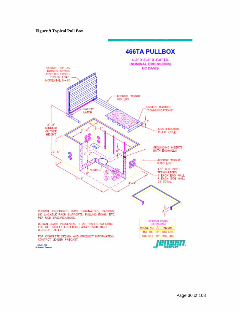
NAM Numbering, Matrix and Labeling Requirements NAM Numbering
• Assign the NAM numbers to the floor plans. Contact the Communication Resources (CR) Project Engineer to obtain blocks of NAM numbers for voice, data, fiber to the desktop (FTTD) and master antenna television (MATV). The A&E Project Manager will provide the name and number of the CR Project Engineer.
NAM Matrices
• The consultant shall provide a NAM Matrix spread sheet (voice, data, MATV and
FTTD), which identifies all NAM locations, TR and cross-connects. • • Reference Tables 6, 7, 8 and 9. • Specify that the contractor shall use and update the NAM Matrices during the project
construction. Table 6 VOICE NAM MATRIX Bldg: CAAN: Zone:
NAM ROOM #
VOICE NAM #
IDF TERM #
BDF/IDF ROOM #
BDF/IDF TERM #
REFERENCE DRAWING #
RISER CABLE #
RISER PAIR #
Table 7 DATA NAM MATRIX
NAM ROOM#
DATA NAM#
OUTLET NO.
BDF/IDF ROOM#
BDF/IDF TERM#
REFERENCE DRAWING#
Table 8 MATV NAM MATRIX
NAM ROOM #
MATV NAM #
OUTLET NO.
BDF/IDF ROOM#
BDF/IDF TERM#
REFERENCE DRAWING#

Page 33 of 103
Table 9 FTTD NAM MATRIX
NAM ROOM
#
FTTD NAM #
BLDG #
CAAN #
IDF ROOM #
FLOOR #
HOUSING #
POSITION NUMBER IN
HOUSING
CABLE I.D. #
NAM TYPE
MEDIA TYPE
REFERENCE DRAWING NUMBER
NAM Labeling
• Each 8-pin, 8-conductor module will be assigned a unique 6-digit (7-digit for FTTD) NAM number. NAM's are to be labeled either on a pre-printed label or using an electronic label maker such as the Brother P-Touch®. The electronic label shall contain black, Helvetica, Size 1 Font, block letters on a white background. When printing labels on a desktop printer, the size and type of font shall be black, Helvetica, size 10, block letters on a white background.
• The NAM number shall be placed in the window area on the faceplate above and below
the NAM in the space provided as shown in Figure 10. • When a surface mounted interface box is used, the top of the box shall be labeled as
shown in Figure 11. • Fiber to the Desktop (FTTD) NAM’s shall be labeled as shown in Figure 12. (Change
picture to an angled conn) Figure 10 Labeling Flush Mounted WAO
2XXXXXX 7XXXXX
2XXXXX 7XXXXX
2XXXXX 7XXXXX
2XXXXX 7XXXXX
2XXXXX 7XXXXX 7XXXXX
2 Port 4 Port 5-6 Ports

Page 34 of 103
Figure 11 Labeling Surface Mounted WAO
Figure 12 Labeling Flush Mounted FTTD WAO
2XXXXXX 7XXXXX F9XXXXX F9XXXXX
Page 35 of 103
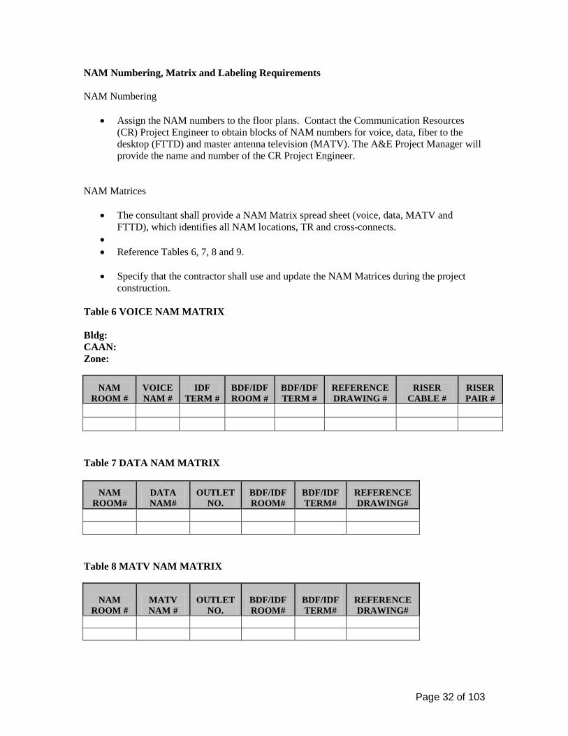
Outside Plant and Riser Cable Labeling Requirements
Fiber Optic Cable Termination Cabinet/Housing Labeling
• Fiber optic termination housings shall be labeled using the metal panel provided by the termination-housing manufacturer. The panel shall be overlaid with one-piece, self-adhesive, full-size, laser printer generated label sheet adhered to the slide out metal panel or inside door of the enclosure, where applicable using an 8.5-inch by 11-inch laser printable adhesive backed sheet, part number Avery 5165 or equal. Reference Figure 13.
• Fiber strand numbering shall be consistent with the Consecutive Fiber Numbering (CFN)
sequence as identified in TIA/EIA 568-B.1. This fiber stand numbering sequence shall be accomplished at each terminated end of the fiber optic cable. The rolling of fiber optic strands, as identified in TIA/EIA 568-B.1 as Reverse Pair Positioning (RPP) shall not be used on the UC Davis campus.
Figure 13 Fiber Optic Closet Connector Housing Labels Example A: 144SM Cable from CAAN: 4881 to CAAN: 4668 & multiple other locations using 568SC Duplex Closet Connector Panel.
CAAN: 4881 BDF 1.1
4668 3845 4719 MH32-160NW
MH32-160NW
MH30-160NW
4861 6F / MH29-
156NW 6F MH29-156NW 4684 4684 4684 4684
IDF 1.1 IDF 1.1 IDF 1.1 IDF 1.1 IDF 1.1 IDF 1.1 IDF 1.1 IDF 1.1 IDF 1.1 IDF 1.1 IDF 1.1 IDF 1.1
1 2 13 14 25 26 37 38 49 50 61 62 73 74 85 86 97 98 109 110 121 122 133 134 3 4 15 16 27 28 39 40 51 52 63 64 75 76 87 88 99 100 111 112 123 124 135 136
5 6 17 18 29 30 41 42 53 54 65 66 77 78 89 90 101 102 113 114 125 126 137 138
7 8 19 20 31 32 43 44 55 56 67 68 79 80 91 92 103 104 115 116 127 128 139 140
9 10 21 22 33 34 45 46 57 58 69 70 81 82 93 94 105 106 117 118 129 130 141 142
11 12 23 24 35 36 47 48 59 60 71 72 83 84 95 96 107 108 119 120 131 132 143 144
Example B: 72SM Cable from CAAN: 4021 ADF 3 to CAAN: 4343 BDF 0.1 using 568SC Duplex Closet Connector Panel.
CAAN: 4021 ADF 3
4343 4343 4343 4343 4343 4343
BDF 0.1 BDF 0.1 BDF 0.1 BDF 0.1 BDF 0.1 BDF 0.1
1 2 13 14 25 26 37 38 49 50 61 62 3 4 15 16 27 28 39 40 51 52 63 64 5 6 17 18 29 30 41 42 53 54 65 66 7 8 19 20 31 32 43 44 55 56 67 68 9 10 21 22 33 34 45 46 57 58 69 70
11 12 23 24 35 36 47 48 59 60 71 72 Example C: 48SM Cable from CAAN: 3843 IDF 1.1 to CAAN: 4881 BDF 1.1 using 568SC Duplex Closet Connector Panel

Page 36 of 103
CAAN: 3843 IDF 1.1
4881
BD
F 1.
1 2 4 6 8 10 12
4881
BD
F 1.
1 26 28 30 32 34 36
1 3 5 7 9 11 25 27 29 31 33 35
4881
BD
F 1.
1 14 16 18 20 22 24
4881
BD
F 1.
1
38 40 42 44 46 48
13 15 17 19 21 23 37 39 41 43 45 47
Source CAAN Number (Beginning of Fiber Strand) Destination CAAN Number (End Point of Fiber Strand) ADF/BDF/IDF Number (opposite terminated location of strand) (where applicable) Fiber optic housings connector panels Labeling
• Fiber strand number 1 (Blue) shall occupy fiber port number 1 in the upper most left position of the first duplex bulkhead connector installed in the connector panel placed in the first slot on the left side of the housing.
• Fiber strand number 2 (Orange) shall occupy fiber port number 2 of the same duplex
bulkhead connector installed in the connector panel. This number 2 port is to the immediate right of fiber port number 1.
• All remaining fiber optic strands shall be number consecutively left to right, top to
bottom. Reference Figure 14.

Page 37 of 103
Figure 14 568SC Duplex Fiber Optic Connector Panel Numbering Sequence
1
2
3
4
5
6
Fiber Optic Splice Shelf Labeling
• Fiber optic splice shelves and drawers shall be labeled sequentially from top to bottom using an adhesive backed, labeling stock type of paper printed on a laser printer. Trim the paper to fit the inside door of the splice housing or shelf.
• Identify in tabular form the splice tray, position number and the fiber strand spliced at
that location. Labeling shall consist of the cable number, the fiber optic strand number and the strand type.
Fiber Optic Cable Sheath Labeling
• Fiber optic cables located inside buildings shall have their sheaths labeled within 12 inches of the fiber termination housing, the point at which the cable enters and/or exits the room and at one mid-point location when the cable is installed in a cable tray or ladder rack, as a minimum.
• Fiber optic cables located in maintenance holes (MH) shall have their sheaths labeled in
at least one location that is visible from grade level. MH’s and PB’s containing splice closures shall be labeled on each side of the splice closure and shall be visible from grade level.
• OSP fiber optic cables shall contain an orange fiber optic warning tag with large black
letters. Panduit type PCV-FOR, or equal. Reference Figure 15.

Page 38 of 103
• The fiber optic cable label shall consist of a plastic yellow and black type tag with a self-
laminating cover for use with pre-printed labels and attaches with a plastic tie wrap. Panduit type PST-FO, self-laminating GMV4 Rigid Vinyl is the preferred manufacturer, or equal. Reference Figure 15.
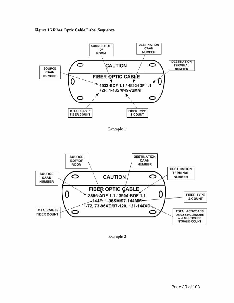
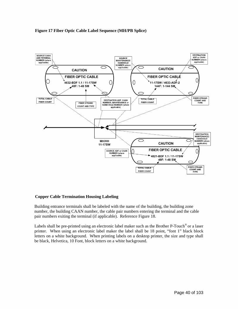
• Reference Figure 16 for cable tag labeling requirements. • See Figure 17 for Fiber Optic Cable Label Sequence (MH/PB Splice)
Figure 15 Fiber Optic Cable Sheath Labels
Page 39 of 103
Figure 16 Fiber Optic Cable Label Sequence
Example 1
Example 2
Page 40 of 103
Figure 17 Fiber Optic Cable Label Sequence (MH/PB Splice)
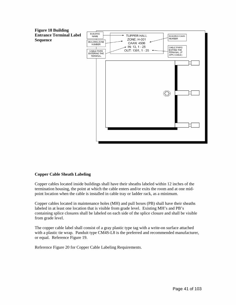
Copper Cable Termination Housing Labeling Building entrance terminals shall be labeled with the name of the building, the building zone number, the building CAAN number, the cable pair numbers entering the terminal and the cable pair numbers exiting the terminal (if applicable). Reference Figure 18.
Labels shall be pre-printed using an electronic label maker such as the Brother P-Touch® or a laser printer. When using an electronic label maker the label shall be 18 point, “font 1” black block letters on a white background. When printing labels on a desktop printer, the size and type shall be black, Helvetica, 10 Font, block letters on a white background.
Page 41 of 103
Figure 18 Building Entrance Terminal Label Sequence
Copper Cable Sheath Labeling Copper cables located inside buildings shall have their sheaths labeled within 12 inches of the termination housing, the point at which the cable enters and/or exits the room and at one mid-point location when the cable is installed in cable tray or ladder rack, as a minimum.
Copper cables located in maintenance holes (MH) and pull boxes (PB) shall have their sheaths labeled in at least one location that is visible from grade level. Existing MH’s and PB’s containing splice closures shall be labeled on each side of the splice closure and shall be visible from grade level.
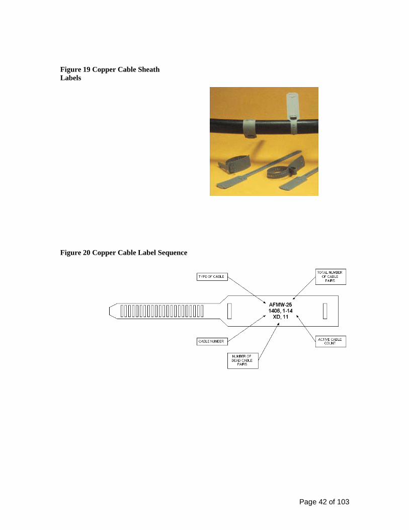
The copper cable label shall consist of a gray plastic type tag with a write-on surface attached with a plastic tie wrap. Panduit type CM4S-L8 is the preferred and recommended manufacturer, or equal. Reference Figure 19. Reference Figure 20 for Copper Cable Labeling Requirements.
Page 42 of 103
Figure 19 Copper Cable Sheath Labels
Figure 20 Copper Cable Label Sequence

Page 43 of 103
Commissioning of Communications 27 08 00 Testing Requirements for Copper and Fiber Optic Horizontal Cables General
• Test and document each horizontal cable segment separately. • Test each end-to-end cable link.
The installation contactor shall perform testing on all installed cabling systems. All documented test results shall be provided to the Communications Resources (CR) representative for review and approval. Prior to testing, the contractor shall notify the CR representative 48 hours in advance and provide a testing schedule. CR has the right to verify the set-up and procedures of testing instruments and be present during cable certification. The contractor shall provide calibration certifications for testing equipment to be used, prior to commencement of testing. All tests conducted before approval will be null and voided. UTP Horizontal Voice and Data Cable Testing
• UC Davis requires all UTP horizontal station cables be Permanent Link tested with a Level III or later tester for full compliance with TIA/EIA 568-B.1 and B.2, ( including addendums) Category 5e specifications. Contractor is required to use Cat 6 test cords, by same manufacturer as test equipment, and save all graphs when testing.
FTTD Horizontal and Riser/Backbone Fiber Cable Testing UC Davis requires that all horizontal single-mode Fiber to the Desktop (FTTD) cables be tested for full compliance with TIA/EIA 568-B.1 and B.3 (including addendums). Field-testing instruments for single-mode fiber optic cabling shall meet the requirements of ANSI/TIA/EIA-526-7 using testing Method A and B. Reference TIA/EIA-568-B.3 for additional test requirements. Fiber optic testing procedures Link attenuation (Power Meter)
• All horizontal single-mode fiber optic cables shall be tested for link attenuation (i.e. power insertion loss) as referenced in TIA/EIA-568-B.1, Section 11.3 and/or University Standards, which is ever more stringent. See Table 10 for proper fiber testing measures.
• All strands shall be tested in a bi-directional method at both wavelengths with a Power
Source and Meter capable of recording and plotting data.
• TIA/EIA 568-B.1 and TIA/EIA 526-7 outlines the steps required to test single-mode fiber optic cable.

Page 44 of 103
• Ensure that all connectors (on both sides of the mating sleeve) are clean prior to testing. Do not use canned air to clean the connectors or mating sleeves. Some can air products can leave a fluid buildup and/or create a static charge.
Optical Time Domain Reflectometer (OTDR)
• Horizontal cables shall be tested bi-directional and at both wave lengths for dB loss and end-to-end total installed distance with an OTDR. Each trace shall indicate the cable length and 2-Point dB loss between the A and B test trace cursors.
• All OTDR traces shall be accomplished using a manufactured and terminated corning
MM/SM, as appropriate, glass launch cable. OTDR traces shall use the Medium Smooth setting and readings taken in feet.
• Cables to be tested at the appropriate pulse width to accommodate short cable lengths
(MM cable at maximum 5 ns/6.6 ft and SM maximum 20 ns/6.6 ft). Table 10 Maximum Loss Measurements
Maximum Loss Measurements for Installed Fiber Optic Cables Mated Connector Loss: 0.5 dB per mated pair Connector Loss: 0.5 dB per connector Splice Loss: Fusion Multimode Fusion Single-mode Mechanical
0.15 dB 0.06 dB 0.3 dB
Fiber loss: Multimode 3.5 dB/km @ 850 nm 1.0 dB/km @ 1300 nm
Fiber loss: Single-mode 0.4 dB/km @ 1310 nm (Outside Plant Cable) 0.3 dB/km @ 1550 nm (Outside Plant Cable) 1.0 dB/km @ 1310 nm (Inside Plant Cable) 0.75 dB/km @ 1550 nm (Inside Plant Cable)
Test Result Documentation Power meter fiber optic test results shall be provided by tester-generated documentation in hard copy (paper copy) and soft copy (CD electronic copy). Provide in manufacturer software format. OTDR fiber optic traces shall be provided in hard copy (paper copy) and soft copy (CD electronic copy) that is readable by Corning Cable Systems, GN Net Test or Fluke LinkWare software. Test results shall be organized by NAM# and closet in an orderly fashion. CD electronic copy shall have the latest version of software burned on it for viewing test results and a copy of the transmittal letter explaining any issues regarding the test results (skipped #’s, cause of failures, etc.). CD shall have a computer generated label with:
• Contractors Name • Date • UC Davis Bldg name, CAAN and project number • Contents (Fiber/copper Test Results, etc.)

Page 45 of 103
Structured Cabling 27 10 00 . Communications Resources shall be consulted early during the utilities planning phase of the project since each site may have technical requirements requiring a modification of these specifications. Communications Equipment Room Fittings 27 11 00
Communications Entrance Protection 27 11 13 Building Entrance Terminals
• Outside Plant copper cables entering the ADF/BDF/IDF shall be terminated on wall-mounted building entrance protector terminal(s) equipped with digital solid state (4B1FS-240) protector modules; 4B1FS-240 includes heat coils for sneak current protection.
• Building entrance terminals shall not be located directly above the room entrance
conduits, slots or sleeves. Terminals shall be mounted in a location on the backboard that shall allow sufficient space for future cable and cross-connect installations.
• Copper entrance cables up to and including 300 pairs shall be terminated on protected
building entrance terminals equipped with a splice chamber and factory installed large 710-type splice modules in the splice chamber (field side) and 110 type terminations on the output (equipment side). Building entrance terminal shall have a lockable cover; Circa model 1880ECS1-100, or equal. Cable shall be blocked with an approved manufactured seal to prevent the gel filled compound from escaping; See Figure 21.
Figure 21 Circa 1880ECS1-100
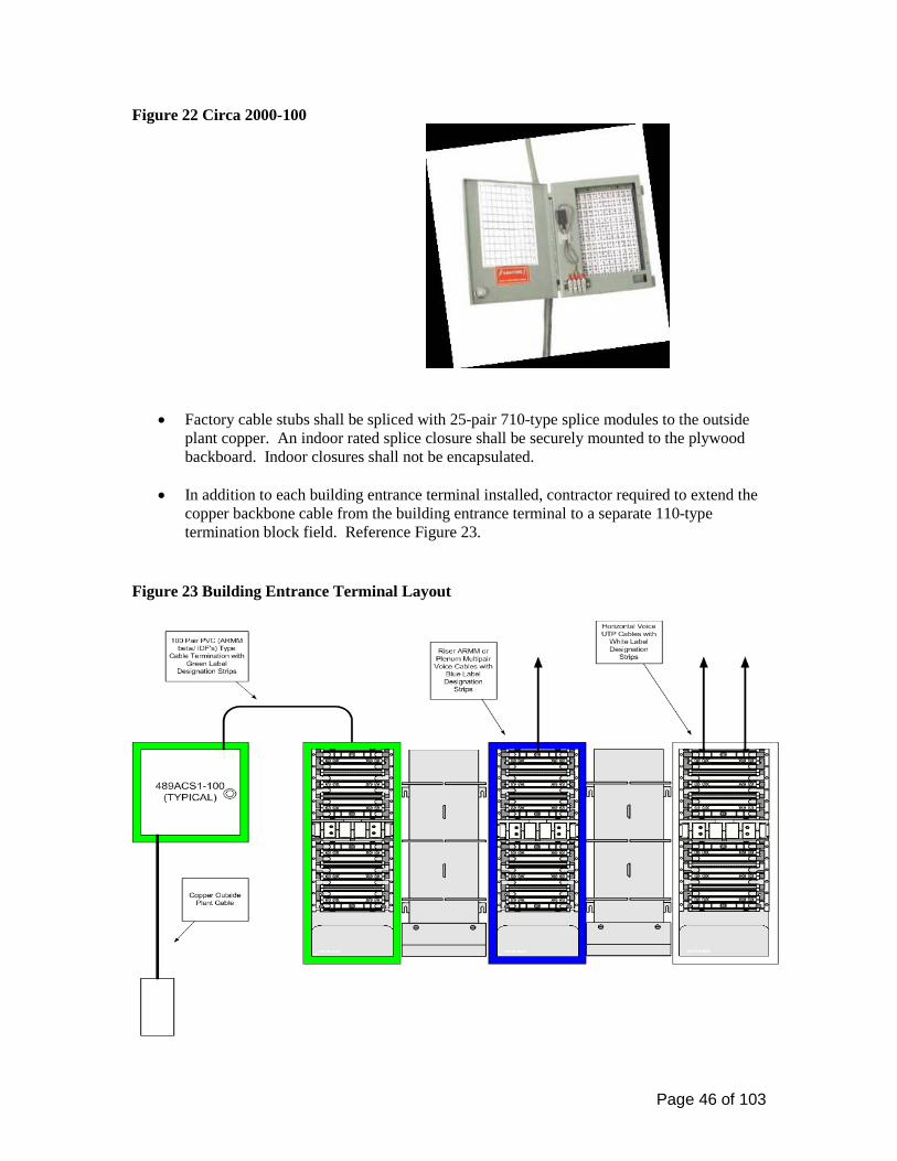
• Copper entrance cables 301 pairs and larger shall be terminated on individual 100 pair protected terminals equipped with a factory installed, 26AWG swivel cable stub in the splice chamber (field side) and on the output (equipment side): stub-in, stub-out configuration. Cable stubs shall be no shorter than 2 feet in length after installation. Circa model 2000-100, or equal; Figure 22
Page 46 of 103
Figure 22 Circa 2000-100
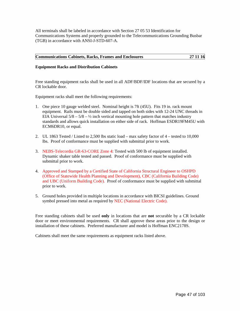
• Factory cable stubs shall be spliced with 25-pair 710-type splice modules to the outside
plant copper. An indoor rated splice closure shall be securely mounted to the plywood backboard. Indoor closures shall not be encapsulated.
• In addition to each building entrance terminal installed, contractor required to extend the
copper backbone cable from the building entrance terminal to a separate 110-type termination block field. Reference Figure 23.
Figure 23 Building Entrance Terminal Layout
Page 47 of 103
All terminals shall be labeled in accordance with Section 27 05 53 Identification for Communications Systems and properly grounded to the Telecommunications Grounding Busbar (TGB) in accordance with ANSI-J-STD-607-A. Communications Cabinets, Racks, Frames and Enclosures 27 11 16 Equipment Racks and Distribution Cabinets Free standing equipment racks shall be used in all ADF/BDF/IDF locations that are secured by a CR lockable door. Equipment racks shall meet the following requirements: 1. One piece 10 gauge welded steel. Nominal height is 7ft (45U). Fits 19 in. rack mount
equipment. Rails must be double sided and tapped on both sides with 12-24 UNC threads in EIA Universal 5/8 – 5/8 – ½ inch vertical mounting hole pattern that matches industry standards and allows quick installation on either side of rack. Hoffman ESDR19FM45U with ECM6DR10, or equal.
2. UL 1863 Tested / Listed to 2,500 lbs static load – max safety factor of 4 – tested to 10,000 lbs. Proof of conformance must be supplied with submittal prior to work.
3. NEBS-Telecordia GR-63-CORE Zone 4: Tested with 500 lb of equipment installed. Dynamic shaker table tested and passed. Proof of conformance must be supplied with submittal prior to work.
4. Approved and Stamped by a Certified State of California Structural Engineer to OSHPD (Office of Statewide Health Planning and Development), CBC (California Building Code) and UBC (Uniform Building Code). Proof of conformance must be supplied with submittal prior to work.
5. Ground holes provided in multiple locations in accordance with BICSI guidelines. Ground symbol pressed into metal as required by NEC (National Electric Code).
Free standing cabinets shall be used only in locations that are not securable by a CR lockable door or meet environmental requirements. CR shall approve these areas prior to the design or installation of these cabinets. Preferred manufacturer and model is Hoffman ENC2178S. Cabinets shall meet the same requirements as equipment racks listed above.

Page 48 of 103
Equipment Rack and Cabinet Dimensions Table 11 Equipment Rack and Cabinet Dimensions
Type of Termination
Equipment Rack
Dimensions (H x W)
Distribution Cabinet
Dimensions (H × W × D)
ADF 84” × 19” (3 each) 84” × 24” × 32” (3 each)
BDF 84” × 19” (5 each) 84” × 24” × 32” (5 each)
IDF 84” × 19” (4 each) 84” × 24” × 32” (4 each)
Note: Overall height of all standing equipment racks and cabinets shall not exceed 84 inches.
Electrical Requirements Refer to Section 27 00 00 Telecommunications Space Electrical Requirements and Figures 24-28.
Equipment Rack and Cabinet Layouts Area Distribution Frame (ADF) ADF cabinets are used only in ADF locations. Planning for a new ADF shall be coordinated with the Communications Resources, Project Engineer.
Page 49 of 103
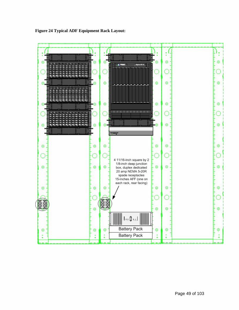
Figure 24 Typical ADF Equipment Rack Layout:

Page 50 of 103
Figure 25 Typical ADF Cabinet Layout:
4 11/16" X 4" 11/16 X 2 1/8" DEEP JUNCTION BOX,
DUPLEX 30 AMPRECEPTACLE
15"
4 11/16" X 4" 11/16 X 2 1/8" DEEP JUNCTION BOX, DUPLEX 30 AMP
RECEPTACLE
84"
24"
SD
5"
SD
Smart-UPS
1 4 0 0
Test
AMERICAN POWER CONVERSION
BATTERY PACK
BATTERY PACK
SD
SD
SD
SD
SD
BigIron 8000FOUNDRYNETWORKS
Page 51 of 103
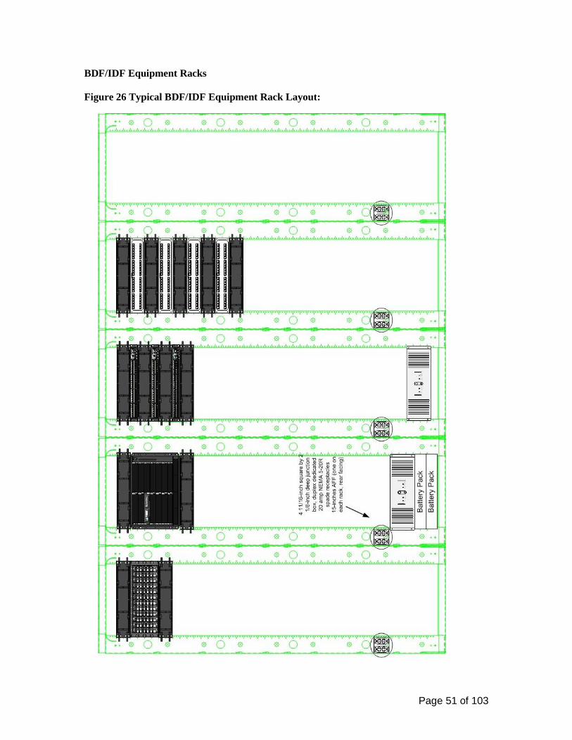
BDF/IDF Equipment Racks Figure 26 Typical BDF/IDF Equipment Rack Layout:
Page 52 of 103
IDF Equipment Racks Figure 27 Typical IDF Equipment Rack Layout:

Page 53 of 103
Communications Termination Blocks and Patch Panels 27 11 19 Data Patch Panels. 1. UTP cable patch panels that provide data service to WAO’s shall meet the following
specifications: o High density, 8 port 8P8C module groupings on the front to 110-type IDC PCB mounted
connectors on the back. Panels shall have front and rear labeling designation strips and rear cable management. Terminate 8P8C modules with universal T568A wiring.
o Ortronics® Clarity5E, Part number OR-PHD5E8U48 (48 port), or equal.
2. Patch Panels shall meet specified performance requirements as listed in Table 12.
3. Patch panels shall be manufactured by an ISO 9001 Certified Manufacturer and be fully compliant with ISO/IEC/DIS-11801 standard and meet FCC specifications where applicable. These products shall also be UL® certified, where applicable.
4. The patch panels shall be labeled below the 8P8C module as shown in Figure 28.
5. Ortronics Cable Management Panel, OR-808044915 or equal is used in conjunction with the Hoffman Vertical D-Ring Cable Manager ECM6DR10.
Table 12 350 MHz Data Patch Panel Specifications (UL certified testing laboratory)
Data Patch Panel Termination Hardware Specifications
Construction (24 and 48 Port Patch Panels)
Category 5e to 110 IDC, 568A wiring, 8P8C, high density, 8 port, rear cable management, front and rear designation strips, 19” (483mm) wide by 1.75” (45mm) high (24 port) and 3.5” (89mm) high (48 port), Low emission IDC contacts, TIA/EIA 568-B.2 compliant and UL Listed
Electrical Data (tested at 250MHz) Return Loss: 21.0 dB Attenuation: 0.4 dB Power Sum-NEXT: 41.0 dB Power Sum-ELFEXT: 34.0 dB Power Sum-ACR Channel: 4.9 dB Active Live Channel Testing 0.17 errors per minute allowable
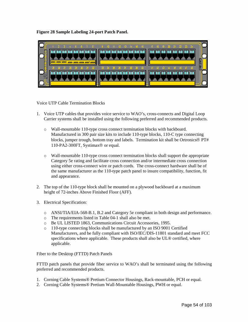
Page 54 of 103
Figure 28 Sample Labeling 24-port Patch Panel.
Voice UTP Cable Termination Blocks 1. Voice UTP cables that provides voice service to WAO’s, cross-connects and Digital Loop
Carrier systems shall be installed using the following preferred and recommended products. o Wall-mountable 110-type cross connect termination blocks with backboard.
Manufactured in 300 pair size kits to include 110-type blocks, 110-C type connecting blocks, jumper trough, bottom tray and labels. Termination kit shall be Ortronics PT# 110-PA2-300FT, Systimax or equal.
o Wall-mountable 110-type cross connect termination blocks shall support the appropriate
Category 5e rating and facilitate cross connection and/or intermediate cross connection using either cross-connect wire or patch cords. The cross-connect hardware shall be of the same manufacturer as the 110-type patch panel to insure compatibility, function, fit and appearance.
2. The top of the 110-type block shall be mounted on a plywood backboard at a maximum
height of 72-inches Above Finished Floor (AFF).
3. Electrical Specification:
o ANSI/TIA/EIA-568-B.1, B.2 and Category 5e compliant in both design and performance. o The requirements listed in Table 04-1 shall also be met. o Be UL LISTED 1863, Communications Circuit Accessories, 1995. o 110-type connecting blocks shall be manufactured by an ISO 9001 Certified
Manufacturers, and be fully compliant with ISO/IEC/DIS-11801 standard and meet FCC specifications where applicable. These products shall also be UL® certified, where applicable.
Fiber to the Desktop (FTTD) Patch Panels FTTD patch panels that provide fiber service to WAO’s shall be terminated using the following preferred and recommended products. 1. Corning Cable Systems® Pretium Connector Housings, Rack-mountable, PCH or equal. 2. Corning Cable Systems® Pretium Wall-Mountable Housings, PWH or equal.
Page 55 of 103
• Corning Cable Systems® Closet Connector Housing Panels, CCH-CP12-A9, Single-mode LC Adapter Duplex, or equal:
3. Corning Cable Systems Unicam® Single-mode LC Ultra Polish connector, Part number 98-
200-98, or equal.
4. All rack and wall-mounted fiber optic closet connector housings shall be labeled in accordance with Figure 15.
5. Housing and connector panels shall be of the same manufacturer as the fiber optic cable and connectors to ensure proper compatibility, fit, function, appearance and the highest campus wide system performance levels and warranty.
Communications Cable Management and Ladder Rack 27 11 23
Communications Rack Mounted Power Protection and Power Strips 27 11 26
Communications Backbone Cabling 27 13 00 A backbone distribution system provides connection between the Telco Central Office (CO), campus Network Operations Center (NOC) and building ADF’s, BDF’s and IDF’s. Campus connection consists of Outside Plant (OSP) copper unshielded twisted pair (UTP) cable and/or single-mode fiber optic cable. Building connection consists of Inside Plant (ISP) copper unshielded twisted pair (UTP) and single-mode fiber cable. Backbone distribution system is to be installed in a star topology. UC Davis recognizes a multiple hierarchical level campus backbone design as illustrated in Figure 29. Communications Copper Backbone Cabling 27 13 13 Building Backbone Inside Plant UTP Copper Cable The building backbone consists of the riser cable and the supporting infrastructure within a building or cluster of buildings that connects the Telecommunications Spaces (ADF/BDF/IDF’s within the ER/TR’s). Table 13 lists the following color codes for cross connect fields. Table 13 shall be used to identify horizontal and riser cables in accordance with TIA/EIA 606-A.

Page 56 of 103
Table 13 Cross Connect Field Color Codes
TERMINATION TYPE COLOR COMMENTS First level backbone
Blue Terminations of building backbone cable
connecting MC to IC’s Horizontal White Terminations of horizontal cable in TS
Campus backbone Green
Termination of backbone cable between buildings
Figure 29 Star building backbone
Copper Riser Cable Specifications Riser cables shall meet the following requirements:
• UL 444 and 1666, ANSI/TIA/EIA 568-B.2, FCC Part 68, Telecordia GR-111, Category 3, listed as CMR or CMP.
• The type of riser cable shall be ARMM. ARMM riser cables shall be grounded and
bonded in accordance with ANSI-J-STD-607-A requirements, as applicable.
• Plenum rated multi-pair copper cables shall be installed in horizontal (cable tray) installations between the BDF and IDF.
Page 57 of 103
• The riser cable is labeled based on a cable number assigned by Communications Resources. The cable pair count shall also be included in the label.
• Reference Division 27 11 19, Communications Termination Blocks and Patch Panels, for
riser cable termination hardware. Size Copper Riser Cable
• The size of the riser cable is a function of the number of WAO’s supported by the IDF.
• The minimum number of copper riser cable pairs required for each voice NAM = 2 pairs, three (3) or more voice NAMs = 1.5 pairs per NAM.
• Riser cables shall be sized to the next larger, even pair size (i.e. 100, 200, 300, etc).
Outside Plant UTP Copper cable
• Filled core (waterproofing compound) cable shall be used for underground cable installations.
o PE-39 refers to filled cable with solid polyolefin insulation and is suitable for
conduit and direct-buried applications. Cable shall meet ANSI ICEA 7CFR-1755-039 and 390 specifications.
o PE-89 refers to filled cable with formed polyolefin insulation and is suitable for
conduit and direct-buried applications. Cable shall meet ANSI ICEA 7CFR-1755-089 and 890 specifications.
• All outside plant cable shall be Plastic Insulated Conductors (PIC) and the cable jacket
shall be marked with the cable length, cable code, date and manufacturer.
• The minimum bend radius during installation is 10 times the outside diameter of the cable and 8 times the outside diameter after installation. Minimum bend radius shall be maintained during and after the installation phase.
• OSP Copper cable shall have a 10’ service loop prior to terminations at the ADF/BDF/IDF location. CR shall approve the location of this service loop prior to cable installation and termination. OSP copper shall have a loop left in each Manhole/pull box.

Page 58 of 103
Communications Copper Cable Splicing and Terminations 27 13 13.13 Cable Splicing Methods and Splice Closures Copper Cable Splice Methods
• Copper telephone cables shall be spliced using a 710-type, 25-pair, large size, gray in color connector (710SC1-25, 710SD1-25, and 710TC1-25) for underground, direct-buried, aerial and building terminal splices. 710-type connectors shall be 3M-type or equal.
• All splices shall be accomplished using the conductor fold-back method to ease future
splicing and maintenance efforts. Copper Cable Splice Closures
• Copper cable splices (Aerial, Underground, and Direct-buried) shall be sealed using a bolt together, washer-less, stainless-steel type of closure with field adaptable/drillable/reusable 1, 2 and 3 section end plates to match the existing cable plant. Closure shall be Preformed Line Products® (PLP) or equal. No known equal.
• The closure shall be sized to allow sufficient interior space for the fold-back method of
splicing and to allow for the addition of future bridge spliced cables.
• The closure shall be air pressure tested (flash-tested) upon installation and shall not be filled with encapsulant.
• All splice closures shall be properly supported, racked and lashed to the MH racks.
Closures shall be supported by their own individual cable steps, in addition to the steps used to support the cable itself.
• All splice closures shall be properly grounded to the MH grounding and bonding system.
• All splices shall be inspected by a Communication Resources designated representative
prior to the completion and sealing of the splice.
• All copper cables shall be labeled in accordance with Division 27 05 53 Identification for Communication Systems, outside plant and riser cable labeling requirements.
Communications Optical Fiber Backbone Cabling 27 13 23 Fiber Optic Riser Cable Riser cables shall meet the following requirements:
• Conform to CEC Article 770 and comply with the State of California fire codes as interpreted by the Campus Fire Marshal’s office.
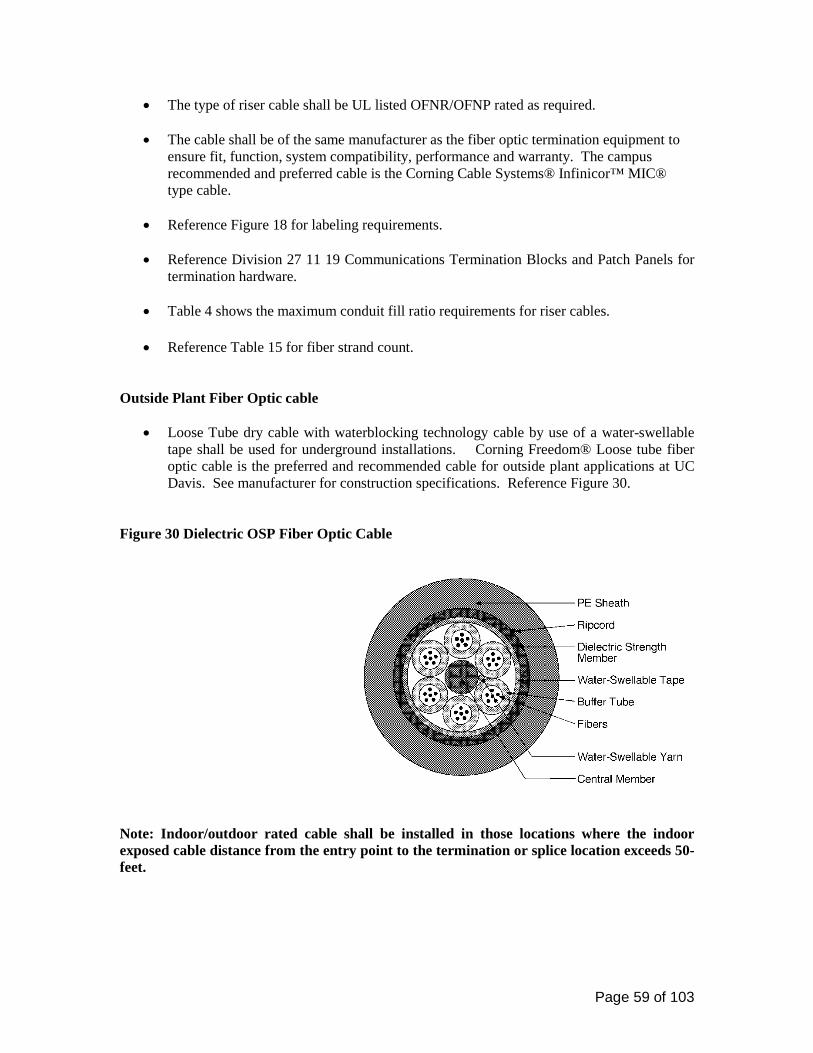
Page 59 of 103
• The type of riser cable shall be UL listed OFNR/OFNP rated as required. • The cable shall be of the same manufacturer as the fiber optic termination equipment to
ensure fit, function, system compatibility, performance and warranty. The campus recommended and preferred cable is the Corning Cable Systems® Infinicor™ MIC® type cable.
• Reference Figure 18 for labeling requirements.
• Reference Division 27 11 19 Communications Termination Blocks and Patch Panels for termination hardware.
• Table 4 shows the maximum conduit fill ratio requirements for riser cables.
• Reference Table 15 for fiber strand count.
Outside Plant Fiber Optic cable
• Loose Tube dry cable with waterblocking technology cable by use of a water-swellable tape shall be used for underground installations. Corning Freedom® Loose tube fiber optic cable is the preferred and recommended cable for outside plant applications at UC Davis. See manufacturer for construction specifications. Reference Figure 30.
Figure 30 Dielectric OSP Fiber Optic Cable
Note: Indoor/outdoor rated cable shall be installed in those locations where the indoor exposed cable distance from the entry point to the termination or splice location exceeds 50-feet.
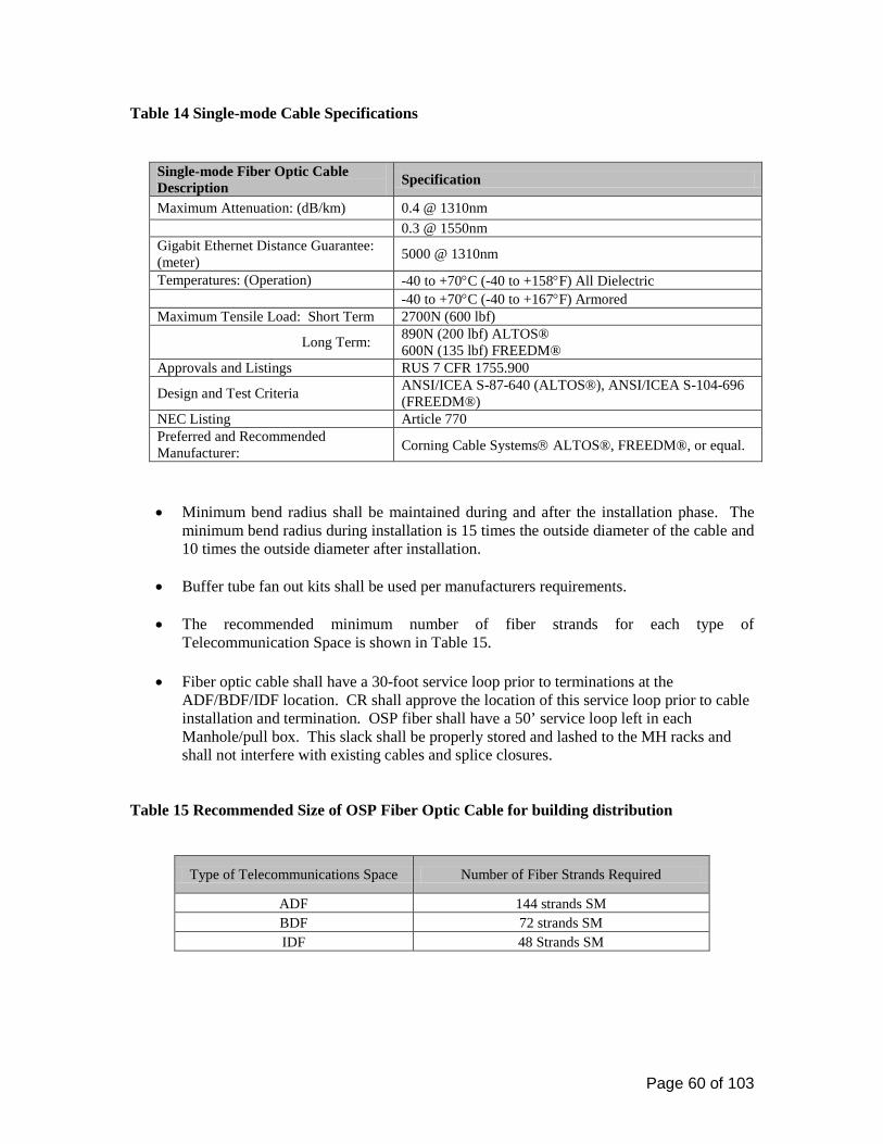
Page 60 of 103
Table 14 Single-mode Cable Specifications
Single-mode Fiber Optic Cable Description Specification
Maximum Attenuation: (dB/km) 0.4 @ 1310nm 0.3 @ 1550nm Gigabit Ethernet Distance Guarantee: (meter) 5000 @ 1310nm
Temperatures: (Operation) -40 to +70°C (-40 to +158°F) All Dielectric -40 to +70°C (-40 to +167°F) Armored Maximum Tensile Load: Short Term 2700N (600 lbf)
Long Term: 890N (200 lbf) ALTOS® 600N (135 lbf) FREEDM®
Approvals and Listings RUS 7 CFR 1755.900
Design and Test Criteria ANSI/ICEA S-87-640 (ALTOS®), ANSI/ICEA S-104-696 (FREEDM®)
NEC Listing Article 770 Preferred and Recommended Manufacturer: Corning Cable Systems ALTOS®, FREEDM®, or equal.
• Minimum bend radius shall be maintained during and after the installation phase. The minimum bend radius during installation is 15 times the outside diameter of the cable and 10 times the outside diameter after installation.
• Buffer tube fan out kits shall be used per manufacturers requirements.
• The recommended minimum number of fiber strands for each type of Telecommunication Space is shown in Table 15.
• Fiber optic cable shall have a 30-foot service loop prior to terminations at the ADF/BDF/IDF location. CR shall approve the location of this service loop prior to cable installation and termination. OSP fiber shall have a 50’ service loop left in each Manhole/pull box. This slack shall be properly stored and lashed to the MH racks and shall not interfere with existing cables and splice closures.
Table 15 Recommended Size of OSP Fiber Optic Cable for building distribution
Type of Telecommunications Space Number of Fiber Strands Required
ADF 144 strands SM BDF 72 strands SM IDF 48 Strands SM
Page 61 of 103
Communications Optical Fiber Splicing and Terminations 27 13 23.13
Fiber Optic Cable Splice Methods
• Confer with Communication Resources when designing the outside plant cable layout.
• Should a field splice be required, single-mode OSP fiber cables shall be fusion spliced only. Mechanical splices shall not be allowed. Heat shrink type fusion protectors with a strength member shall be used for all fusion splices.
• The larger 12-strand 24-inch size splice trays shall be used for single-mode splices to
allow additional space for retaining fiber loops and controlling bend radius.
• All splices shall be inspected by a Communication Resources designated representative prior to sealing the splice.
Fiber Optic Splice Closures:
• Fiber optic cable splices shall be sealed using a hard plastic, bolt together, re-useable/re-sealable type of fiber optic cable closure. Closure shall be Preformed Line Products® Coyote®, Corning Cable Systems, or equal.
• Closure shall allow manufacturer’s recommended slack (typically 8 to 10 ft) within the
closure to facilitate present and future fiber splicing and maintenance activities.
• All splice closures shall be properly supported, racked and lashed to the MH racks. Closures shall be supported by their own individual cable steps, in addition to the steps used to support the cable itself.
• All splice closures shall be properly grounded to the MH grounding system, when
applicable.
• All Fiber Optic cables shall be labeled in accordance with Division 27 05 53 Identification for Communication Systems.
Fiber Optic Connectors Fiber optic cable for outside plant and riser/backbone installations shall be fusion spliced to factory made 568SC Ultra PC Polish type pigtails at the ADF/BDF/IDF:
• Corning Cable Systems® 568SC Ultra PC Polish, 3 meter Single-mode cable assembly, or equal.

Page 62 of 103
Closet Connector and Splice Housings
All fiber optic connectors, termination housings and hardware shall be of the same manufacturer as the installed cable to ensure campus wide network system compatibility, optimum performance, fit, function, appearance and warranty. The preferred and recommended type and manufacturer of fiber optic connectors, termination housings and connector panels shall be Corning Cable Systems, or equal. See manufacturer for specifications. If substitutions are requested by the consultant/contractor, then documented and demonstrated equivalency shall be provided to CR for their review.
1. Corning Cable Systems® Pretium Connector Housings (PCH), Rack-mountable, or equal:
• PCH-02U (up to 72 SC fibers) • PCH-04U (up to 144 SC fibers)
2. Corning Cable Systems® Closet Splice Housings (CSH), Rack-mountable, or equal:
• CSH-03U (288 fibers) • CSH-05U (528 fibers)
3. Corning Cable Systems® Wall-Mountable Closet Housing (WCH), Wall-mountable, or
equal:
• WCH-04P (48 fibers) • WCH-06P (72 fibers)
Rack-mountable Connector Housing Splice Trays, or equal:
• M67-112 (Type 2S, 24 fusion splices) • M67-068 (Type 2R, 6 fusion splices)
Fiber optic cable for outside plant and riser/backbone installations shall be terminated on Duplex 568SC type connector panels at the ADF/BDF/IDF:
• Corning Cable Systems®, CCH-CP12-59 (Preloaded 6 duplex connectors, Single-mode,
Ceramic Insert, Blue, for connecting 12 SC connectors), or equal.
Fiber distribution cabinets (rack and wall-mounted closet connector housings) shall be labeled in accordance with Division 27 05 53 Identification for Communication Systems.

Page 63 of 103
Communications Coaxial Backbone Cabling 27 13 33 Reference MASTER ANTENNA TELEVISION (MATV) SYSTEM Section 27 43 00. Communications Coaxial Splicing and Terminations 27 13 33.13 Communications Horizontal Cabling 27 15 00
UC Davis recognizes two types of cables for use in the horizontal segment: Unshielded Twisted Pair (UTP) and single-mode (SM) fiber optic cable.
1. UTP cable shall be 4-pair, 24 AWG, solid conductor UL Listed Type CMP or OFNP cabling that meets ANSI/TIA/EIA 568-B.1 and B.2 cabling specifications for Category 5e cable, to include any/all current Addendums and Bulletins and shall meet specified specifications and performance requirements.
2. Fiber optic cable shall be a minimum of 4-strands, single-mode, 8.3/125µm, tight-
buffered, indoor cable and meet or exceed OFN-FT6 (Plenum) requirements.
All conductive cable, fiber optic, radio and television, community antenna and network-powered broadband communications systems and associated components shall comply with the following 2001 (or the most current edition at the time of design) California Electric Code (CEC) articles:
• Article 770 Optical Fiber Cables and Raceways • Article 800 Communications Circuits • Article 810 Radio and Television Equipment • Article 820 Community Antenna Television and Radio Distribution • Article 830 Network Powered Broadband Communications Systems
Horizontal cables shall not be spliced, nor will these cables contain manufacturer splices. Cable shall be manufactured, tested, certified and meet the performance requirements listed in Table 16. The maximum total length of horizontal cable from the IDF to WAO not to exceed 295 feet; 328 feet (100 meters) including patch cords (patch panel to equipment and WAO faceplate to workstation). Cable slack shall be provided at the workstation to accommodate future cabling system changes.
1. The minimum amount of slack shall be 6-inches for UTP cables and 36-inches for fiber optic cables at the WAO.
2. Service loops are not recommended in copper cable installation practices. Service loops
placed during the installation of 4-pair horizontal cables were tested and determined to cause Return Loss and NEXT problems on the order of 2-3dB.
Page 64 of 103
Note: These limits apply to all types of horizontal cables. In establishing these limits, a 33-foot allowance was made for the combined length of the manufactured patch cords used to connect equipment at the WAO and IDF locations. Voice Communications Horizontal Cabling 27 15 00.16 WAO Cabling Requirements Work Area Outlets (WAO) providing voice service shall be cabled with a 4-pair, 24AWG, Unshielded Twisted Pair Cable. The following Berk-Tek LANMARK-350 manufacturer part number is the preferred and recommended manufacturer.
1. Berk-Tek LANMARK-350 Plenum, 10032072, White Jacket for voice circuits, or equal.
Data Communications Horizontal Cabling 27 15 00.19 Work Area Outlets (WAO) providing data service shall be cabled with a 4-pair, 24AWG, Unshielded Twisted Pair Cable. The following Berk-Tek LANMARK-350 manufacturer part numbers are the preferred and recommended manufacturer.
1. Berk-Tek LANMARK-350 Plenum, 10032065, Blue Jacket for data circuits, or equal.
2. Berk-Tek LANMARK-350 Plenum, 10032086, Green Jacket for Internal/Local Network connections, or equal.
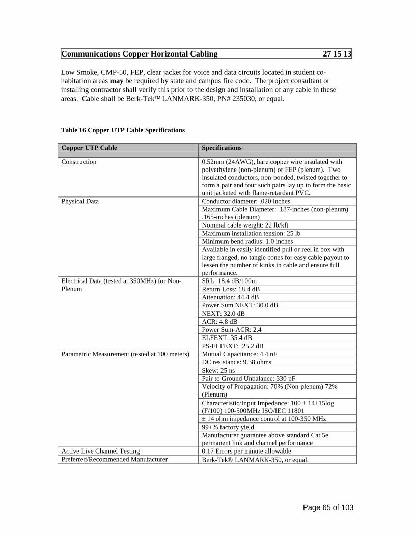
Page 65 of 103
Communications Copper Horizontal Cabling 27 15 13 Low Smoke, CMP-50, FEP, clear jacket for voice and data circuits located in student co-habitation areas may be required by state and campus fire code. The project consultant or installing contractor shall verify this prior to the design and installation of any cable in these areas. Cable shall be Berk-Tek LANMARK-350, PN# 235030, or equal. Table 16 Copper UTP Cable Specifications Copper UTP Cable Specifications
Construction 0.52mm (24AWG), bare copper wire insulated with polyethylene (non-plenum) or FEP (plenum). Two insulated conductors, non-bonded, twisted together to form a pair and four such pairs lay up to form the basic unit jacketed with flame-retardant PVC.
Physical Data Conductor diameter: .020 inches Maximum Cable Diameter: .187-inches (non-plenum) .165-inches (plenum) Nominal cable weight: 22 lb/kft Maximum installation tension: 25 lb Minimum bend radius: 1.0 inches Available in easily identified pull or reel in box with large flanged, no tangle cones for easy cable payout to lessen the number of kinks in cable and ensure full performance.
Electrical Data (tested at 350MHz) for Non-Plenum
SRL: 18.4 dB/100m Return Loss: 18.4 dB Attenuation: 44.4 dB Power Sum NEXT: 30.0 dB NEXT: 32.0 dB ACR: 4.8 dB Power Sum-ACR: 2.4 ELFEXT: 35.4 dB PS-ELFEXT: 25.2 dB
Parametric Measurement (tested at 100 meters) Mutual Capacitance: 4.4 nF DC resistance: 9.38 ohms Skew: 25 ns Pair to Ground Unbalance: 330 pF Velocity of Propagation: 70% (Non-plenum) 72% (Plenum) Characteristic/Input Impedance: 100 ± 14+15log (F/100) 100-500MHz ISO/IEC 11801 ± 14 ohm impedance control at 100-350 MHz 99+% factory yield Manufacturer guarantee above standard Cat 5e permanent link and channel performance
Active Live Channel Testing 0.17 Errors per minute allowable Preferred/Recommended Manufacturer Berk-Tek LANMARK-350, or equal.
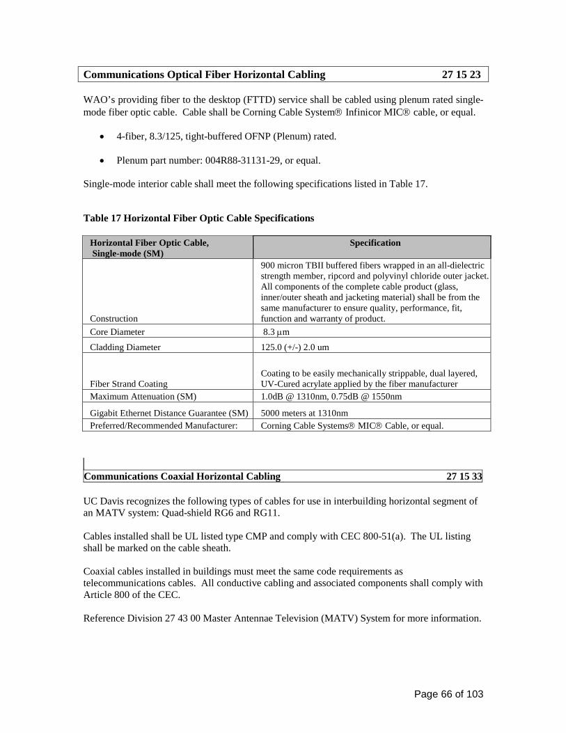
Page 66 of 103
Communications Optical Fiber Horizontal Cabling 27 15 23
WAO’s providing fiber to the desktop (FTTD) service shall be cabled using plenum rated single-mode fiber optic cable. Cable shall be Corning Cable System Infinicor MIC cable, or equal.
• 4-fiber, 8.3/125, tight-buffered OFNP (Plenum) rated.
• Plenum part number: 004R88-31131-29, or equal. Single-mode interior cable shall meet the following specifications listed in Table 17.
Table 17 Horizontal Fiber Optic Cable Specifications
Horizontal Fiber Optic Cable, Single-mode (SM)
Specification
Construction
900 micron TBII buffered fibers wrapped in an all-dielectric strength member, ripcord and polyvinyl chloride outer jacket. All components of the complete cable product (glass, inner/outer sheath and jacketing material) shall be from the same manufacturer to ensure quality, performance, fit, function and warranty of product.
Core Diameter 8.3 µm
Cladding Diameter 125.0 (+/-) 2.0 um
Fiber Strand Coating Coating to be easily mechanically strippable, dual layered, UV-Cured acrylate applied by the fiber manufacturer
Maximum Attenuation (SM) 1.0dB @ 1310nm, 0.75dB @ 1550nm
Gigabit Ethernet Distance Guarantee (SM) 5000 meters at 1310nm Preferred/Recommended Manufacturer: Corning Cable Systems MIC Cable, or equal.
Communications Coaxial Horizontal Cabling 27 15 33 UC Davis recognizes the following types of cables for use in interbuilding horizontal segment of an MATV system: Quad-shield RG6 and RG11. Cables installed shall be UL listed type CMP and comply with CEC 800-51(a). The UL listing shall be marked on the cable sheath. Coaxial cables installed in buildings must meet the same code requirements as telecommunications cables. All conductive cabling and associated components shall comply with Article 800 of the CEC. Reference Division 27 43 00 Master Antennae Television (MATV) System for more information.

Page 67 of 103
Communications Faceplates and Connectors 27 15 43 The Network Access Module (NAM) is the actual connector or jack installed in a faceplate or surface mounted box upon which the UTP, coax and fiber optic cable is terminated on in the work area. The term Work Area Outlet (WAO) refers to the actual faceplate or surface mounted box installed in the work area. Work Area Outlet (WAO) Faceplates, Surface Mount Boxes, Wiremold Adapter and Modules
Faceplates, Surface Mount Interface Boxes and 106-Type Receptacles:
• WAO’s shall be installed using fog white, flush-mounted, front entry, front removable, individual port faceplates and surface mount interface boxes. Faceplate color is recommend to match the décor of the room area and electrical and switch plates where required. Faceplates shall be Ortronics TracJack, or equal. Reference Table 18.
• All voice, data and coax faceplates shall be a minimum of 4-port. Blank modules of the
same color and manufacturer as the faceplate or surface mounted box shall cover all open ports not utilized by a NAM.
o Ortronics TracJack Blank Module, OR-42100002, Fog White, Front Entry/Removable
• FTTD shall be placed in an Ortronics Multimedia Workstation Fib-or-Cop II Outlet. See
manufacturer for specifications.
• Stylistic TracJack Frames, as listed in Table 18, shall be used when installing NAM’s in metallic type surface raceways when a standard type faceplate cannot be used.
• WAO are not to be installed within Modular furniture. WAO to terminate flush on the
wall and extended to the work area with NAM extensions. Coordinate work with furniture installation.
• Angled faceplates are preferred in the Dorm Rooms.
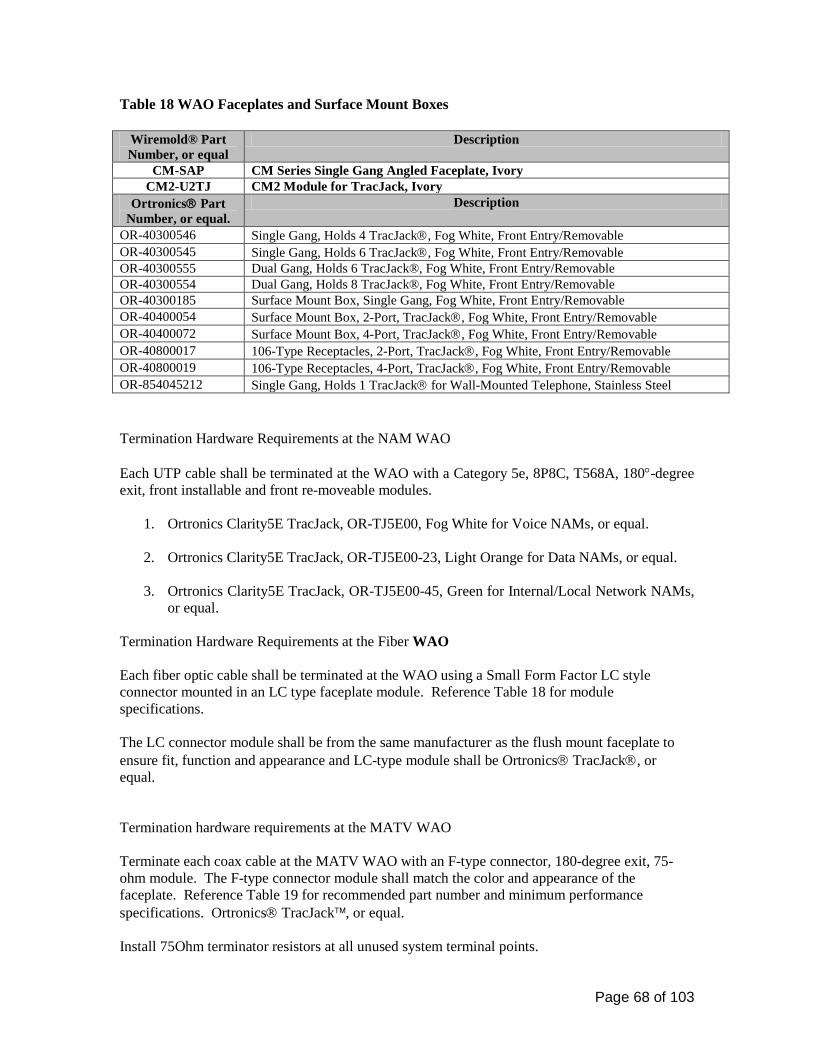
Page 68 of 103
Table 18 WAO Faceplates and Surface Mount Boxes
Wiremold® Part Number, or equal
Description
CM-SAP CM Series Single Gang Angled Faceplate, Ivory CM2-U2TJ CM2 Module for TracJack, Ivory
Ortronics Part Number, or equal.
Description
OR-40300546 Single Gang, Holds 4 TracJack, Fog White, Front Entry/Removable OR-40300545 Single Gang, Holds 6 TracJack, Fog White, Front Entry/Removable OR-40300555 Dual Gang, Holds 6 TracJack®, Fog White, Front Entry/Removable OR-40300554 Dual Gang, Holds 8 TracJack®, Fog White, Front Entry/Removable OR-40300185 Surface Mount Box, Single Gang, Fog White, Front Entry/Removable OR-40400054 Surface Mount Box, 2-Port, TracJack, Fog White, Front Entry/Removable OR-40400072 Surface Mount Box, 4-Port, TracJack, Fog White, Front Entry/Removable OR-40800017 106-Type Receptacles, 2-Port, TracJack, Fog White, Front Entry/Removable OR-40800019 106-Type Receptacles, 4-Port, TracJack, Fog White, Front Entry/Removable OR-854045212 Single Gang, Holds 1 TracJack for Wall-Mounted Telephone, Stainless Steel Termination Hardware Requirements at the NAM WAO Each UTP cable shall be terminated at the WAO with a Category 5e, 8P8C, T568A, 180°-degree exit, front installable and front re-moveable modules.
1. Ortronics Clarity5E TracJack, OR-TJ5E00, Fog White for Voice NAMs, or equal.
2. Ortronics Clarity5E TracJack, OR-TJ5E00-23, Light Orange for Data NAMs, or equal.
3. Ortronics Clarity5E TracJack, OR-TJ5E00-45, Green for Internal/Local Network NAMs, or equal.
Termination Hardware Requirements at the Fiber WAO Each fiber optic cable shall be terminated at the WAO using a Small Form Factor LC style connector mounted in an LC type faceplate module. Reference Table 18 for module specifications. The LC connector module shall be from the same manufacturer as the flush mount faceplate to ensure fit, function and appearance and LC-type module shall be Ortronics TracJack, or equal. Termination hardware requirements at the MATV WAO Terminate each coax cable at the MATV WAO with an F-type connector, 180-degree exit, 75-ohm module. The F-type connector module shall match the color and appearance of the faceplate. Reference Table 19 for recommended part number and minimum performance specifications. Ortronics TracJack, or equal. Install 75Ohm terminator resistors at all unused system terminal points.

Page 69 of 103
Table 19 Coax and Fiber NAM Modules
Ortronics® Part Number, or equal.
Description
OR-63700031 TracJack LC Single-mode, Angled, 45° degree exit, 2 fibers, feed through, Blue, Front Entry/Removable
OR-63700006 TracJack® F-Connector, 180° degree exit, 75 Ohm, Front Entry/Removable Communications Connecting Cords, Devices and Adapters 27 16 00 Communications Patch Cords, Station Cords and Cross Connect Wire 27 16 19 Patch cords shall be from the same manufacturer as the termination hardware to ensure proper compatibility, fit, function, appearance and the highest campus wide system performance levels and warranty. Patch cords shall be manufactured by a TL 9000 and ISO 9001 Certified Manufacturer and be fully compliant with ISO/IEC/DIS-11801 standard and meet FCC specifications where applicable. These products shall also be UL® certified, where applicable. Field fabricated patch cords shall not be used. Patch cords shall be of the same or higher transmission category as the cable system installed. Data Patch Cords: Provided by the University. Voice Cross-Connect Wire Proper selection and installation of cross-connect jumper wire used between cross-connect blocks is essential to the overall performance of the network. The twist shall be maintained to within 0.5 inches of the entry into the cross-connect block. Contractors shall complete the horizontal and riser cross-connections at the IDF location(s). Contractor shall provide sufficient jumper wire (white/blue, 24AWG for voice, white/red, 24AWG for Fire Systems) to complete all identified cross-connects at the IDF locations. Note: Communications Resources to provide the contractor a NAM x-connect assignment spreadsheet.
Fiber Optic Patch Cords: Provided by the University. Note: Generally all patch cords are provided and installed by the university, excluding voice x-connects at the IDF locations. Please contact Communications Resources to determine the need to specify patch cords when designing a project.
Page 70 of 103
Data Communications 27 20 00 Data Communications Wireless Access Points 27 21 33 This chapter establishes the specifications, type, testing and acceptance of a wireless network system. Wireless Access Coverage Adequate provision of wireless NAMs shall be specified in new and remodeled construction projects to provide coverage throughout the area under construction. Wireless Access NAM Wireless access NAM consists of a single data Network Access Module (NAM). The wireless NAM is to be terminated with an 8-position, 8 conductor module and placed into a 2 port surface mount box. Location of the wireless NAM is based on the room design:
1. Standard ceiling height rooms (offices, classrooms, conference rooms, etc.) with drop tile ceiling: leave the NAM, placed within a 2-port surface mount box, concealed above the drop tile ceiling with 10 feet of slack. Place the NAM where it will provide the greatest amount of useable coverage.
2. High ceiling rooms (lecture rooms, auditoriums, etc): depending on the size of the room,
provision for two NAM locations on each side wall at approximately 8’-6” AFF. Install each NAM location with a 4-11/16” square back box flush in the wall with a one port faceplate.
3. Hard cap ceilings: Install the NAM with a 4-11/16” square back box and one port
faceplate on the wall at approximately 8’-6” AFF. Wireless network equipment is university provided and installed.

Page 71 of 103
VOICE COMMUNICATIONS 27 30 00 All campus approved wall phones (with an ADA compliant handset); emergency call boxes and towers shall be installed in accordance with ADA requirements. Installed wall, counter-top and weatherproof telephones, in addition to emergency call boxes and WAO’s, shall meet the requirements of the Americans with Disabilities Act (ADA). This requirement is referenced in ANSI/TIA/EIA 568-B.1. http://www.access-board.gov Voice Communications Telephone Sets, Facsimiles and Modems 27 32 00
Courtesy, Pay, Text, Emergency and Wheel Chair Elevator Telephones shall comply with the American Disabilities Act (ADA) Accessibility Guidelines.
• The mounting height of the device box for Payphone shall be 40-inches Above the Finished Floor (AFF). TTY phone requires a power receptacle at 18” AFF under the Text Telephone.
Note: Wall telephones shall not be installed above or over Laboratory countertops. A standard desktop telephone may be installed in these unique locations. Telephone Sets 27 32 00 Indoor Wall-Mounted Telephone
• A 4-11/16 inch × 2 1/8-inch deep square electrical back box with a single gang plaster ring shall be provided. A minimum 1-inch EMT conduit shall be installed to the cable pathway support system. Place the voice NAM into a single port wall phone plate.
• Provided a 12-inch square clear area around the outlet for the wall phone to be mounted unobstructed.
• See figure 31 for examples.

Page 72 of 103
Figure 31 Wall-mounted Telephone Sets
Elevator Telephone 27 32 00 Ring Down Emergency Telephones 27 32 00 Vandal-resistant Emergency/Information systems provide exceptional clarity, performance and a sense of security. Often used in college campuses, parking facilities, shopping malls, medical centers and industrial campuses. Warranty Equipment shall be warrantied against any defects in material and workmanship, under normal use, for a period of one year from date of installation. In the event system is found by manufacturer to be defective within the warranty period, manufacturer shall repair and/or replace any defective parts, provided the equipment is returned to manufacturer.
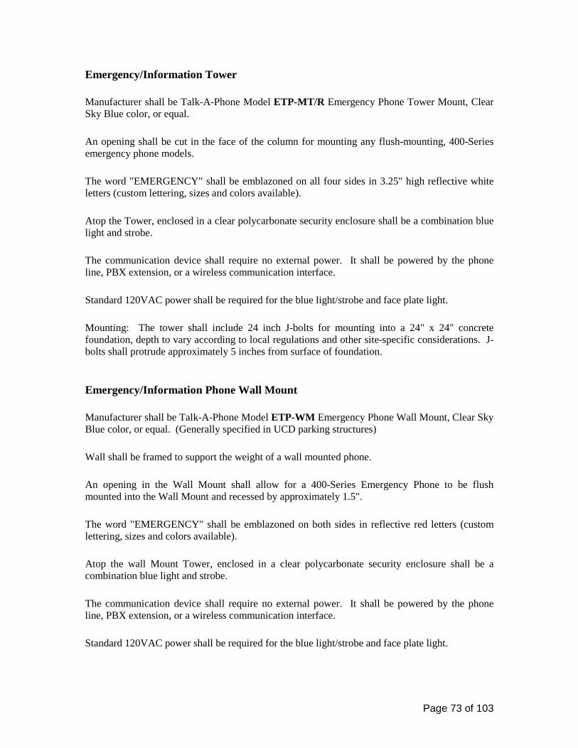
Page 73 of 103
Emergency/Information Tower Manufacturer shall be Talk-A-Phone Model ETP-MT/R Emergency Phone Tower Mount, Clear Sky Blue color, or equal. An opening shall be cut in the face of the column for mounting any flush-mounting, 400-Series emergency phone models. The word "EMERGENCY" shall be emblazoned on all four sides in 3.25" high reflective white letters (custom lettering, sizes and colors available). Atop the Tower, enclosed in a clear polycarbonate security enclosure shall be a combination blue light and strobe. The communication device shall require no external power. It shall be powered by the phone line, PBX extension, or a wireless communication interface. Standard 120VAC power shall be required for the blue light/strobe and face plate light. Mounting: The tower shall include 24 inch J-bolts for mounting into a 24" x 24" concrete foundation, depth to vary according to local regulations and other site-specific considerations. J-bolts shall protrude approximately 5 inches from surface of foundation. Emergency/Information Phone Wall Mount Manufacturer shall be Talk-A-Phone Model ETP-WM Emergency Phone Wall Mount, Clear Sky Blue color, or equal. (Generally specified in UCD parking structures) Wall shall be framed to support the weight of a wall mounted phone. An opening in the Wall Mount shall allow for a 400-Series Emergency Phone to be flush mounted into the Wall Mount and recessed by approximately 1.5". The word "EMERGENCY" shall be emblazoned on both sides in reflective red letters (custom lettering, sizes and colors available). Atop the wall Mount Tower, enclosed in a clear polycarbonate security enclosure shall be a combination blue light and strobe. The communication device shall require no external power. It shall be powered by the phone line, PBX extension, or a wireless communication interface. Standard 120VAC power shall be required for the blue light/strobe and face plate light.
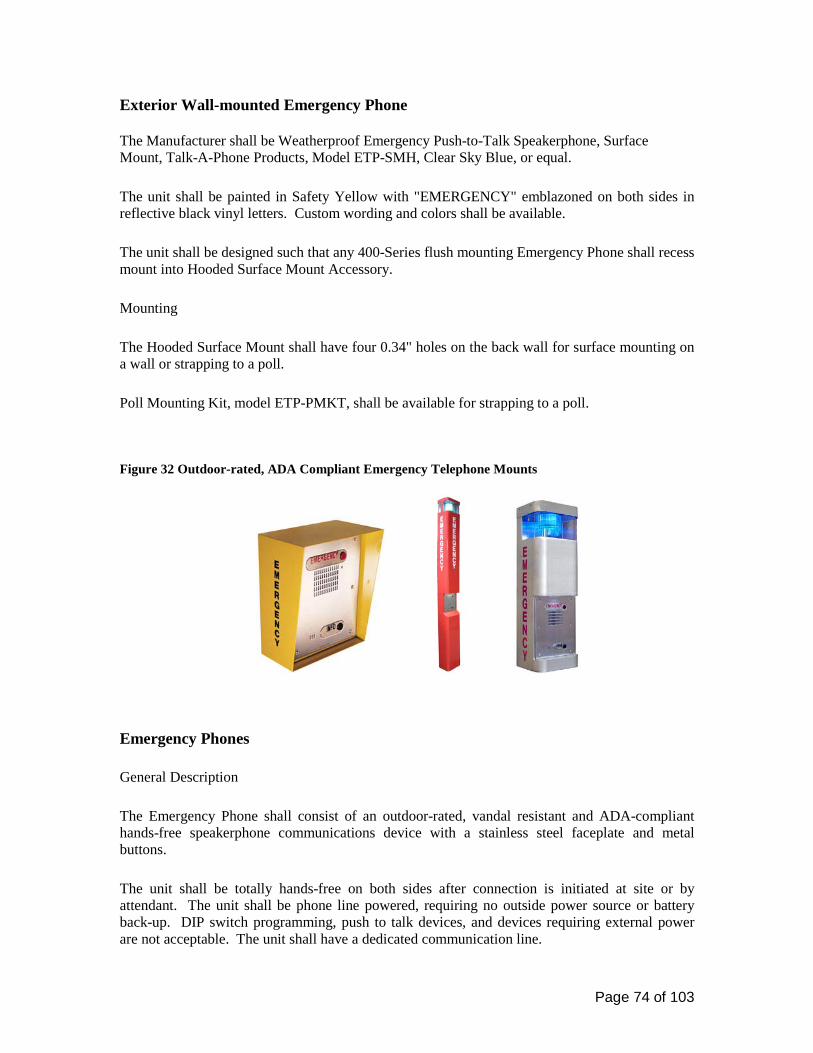
Page 74 of 103
Exterior Wall-mounted Emergency Phone The Manufacturer shall be Weatherproof Emergency Push-to-Talk Speakerphone, Surface Mount, Talk-A-Phone Products, Model ETP-SMH, Clear Sky Blue, or equal. The unit shall be painted in Safety Yellow with "EMERGENCY" emblazoned on both sides in reflective black vinyl letters. Custom wording and colors shall be available. The unit shall be designed such that any 400-Series flush mounting Emergency Phone shall recess mount into Hooded Surface Mount Accessory. Mounting The Hooded Surface Mount shall have four 0.34" holes on the back wall for surface mounting on a wall or strapping to a poll. Poll Mounting Kit, model ETP-PMKT, shall be available for strapping to a poll. Figure 32 Outdoor-rated, ADA Compliant Emergency Telephone Mounts
Emergency Phones General Description The Emergency Phone shall consist of an outdoor-rated, vandal resistant and ADA-compliant hands-free speakerphone communications device with a stainless steel faceplate and metal buttons. The unit shall be totally hands-free on both sides after connection is initiated at site or by attendant. The unit shall be phone line powered, requiring no outside power source or battery back-up. DIP switch programming, push to talk devices, and devices requiring external power are not acceptable. The unit shall have a dedicated communication line.

Page 75 of 103
The Manufacturer shall be Talk-A-Phone Co. (773) 539-1100, 5013 N. Kedzie, Chicago, Illinois 60625, www.talkaphone.com. THERE ARE NO EQUIVALENTS. Options
1. Single Emergency button model ETP-400: The Emergency Phone shall be Talk-A-Phone model ETP-400, or equal and have one red anodized aluminum tactile button labeled "EMERGENCY" and one 0.375" diameter red light emitting diode (LED) labeled "LIGHT ON INDICATES CALL RECEIVED". The unit shall be programmable from a remote location and have a two number dialing capability, reverting to the second number if the first is busy or does not respond.
2. Keypad but no EMERGENCY button model ETP-400KS: The Emergency Phone shall be Talk-A-Phone model ETP-400KS, or equal and have one black anodized aluminum tactile button labeled "CALL", an all metal 12-button keypad and one 0.375" diameter red light emitting diode (LED) labeled "LIGHT ON INDICATES CALL RECEIVED". Using the keypad, the unit shall be capable of dialing any number authorized by the telephone line.
Figure 33 Outdoor-rated, ADA-Compliant Hands-free Emergency Phones
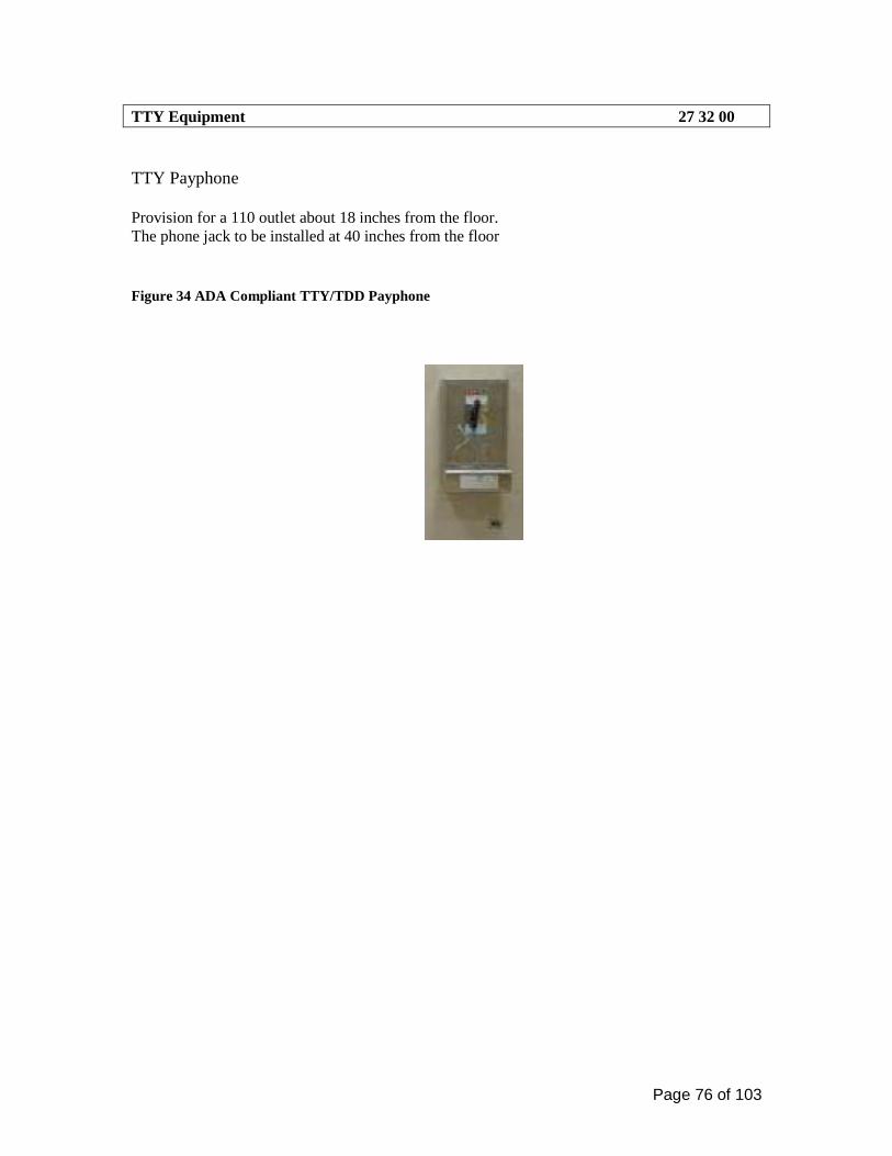
Page 76 of 103
TTY Equipment 27 32 00 TTY Payphone Provision for a 110 outlet about 18 inches from the floor. The phone jack to be installed at 40 inches from the floor
Figure 34 ADA Compliant TTY/TDD Payphone
Page 77 of 103
AUDIO-VISUAL SYSTEMS 27 40 00 The Design Process. UC Davis Audio-Visual (A/V) systems designed and installed in new campus facilities shall consist of one or more of the following three basic elements: • Sound System – A complete sound system meeting the performance standards specified
below to be complimented with an ADA approved assisted listening system.
• Video System – A complete video system consists of various display devices consistent with the intended use of the room and viewable from at least 80% of the room while meeting performance standards listed below.
• Remote Control Systems – A microprocessor controlled audio-visual system provides for the remote control of the various media systems installed in a room. These systems shall follow the standards established by the Classroom committee’s selection of the Smart Panel or equal, which enables a complete room display without extensive operations training.
The design of an A/V system shall be based upon customer requirements, as well as, the intended room function. The electronic equipment and cabling shall be consistent with industry standards. A Communications Resources representative shall have final approval of all A/V systems. All A/V systems designed and installed shall meet the most current Americans with Disabilities Act (ADA) requirements, including assisted listening systems, visual access and accommodations. The design consultant shall ensure all requirements are addressed. Performance Standards All A/V systems shall meet, as a minimum, the following performance standards unless restricted by the published specifications of a specific piece of manufacturer’s equipment. Audio Signal: • Signal-to-Noise Ratio (including cross talk): 55 dB minimum. • Total Harmonic Distortion: 0.1% maximum from 20 Hz to 20,000 Hz. • Frequency Response: +/= -1.0 dB, 20 Hz to 20,000 Hz. Audio Reproduction: • Signal–to–Noise Ratio (including cross talk): 55 dB minimum. • Total Harmonic Distortion: 1% maximum from 30 Hz to 15,000 Hz. • Sound Output Capability: Provide program levels of not less than 95 dB in the seating area
without objectionable distortion, rattle or buzz. Several different samples, such as recorded music and microphones, shall be employed as test signals.
• Hum and Noise: Hum and noise shall be inaudible (below the background noise level of the space) under normal operation and as observed in normal seat locations.
Page 78 of 103
Video Signal: • Signal-to-noise Ratio (peak to RMS) un-weighted DC to 4.2 MHz: 55 dB minimum. • Cross talk: Cross talk (un-weighted DC to 4.2 MHz): 45 dB minimum. • Frequency Response: +/= 0.5 dB to 4.2 MHz. • Line and Field Tilt: 2% minimum. • Differential Gain: 3% maximum. • Differential Phase: 2º-degree maximum. Video Timing: • System Timing: Synchronize coincidence within 50 nanoseconds. • Color Timing: Within 2º-degrees at 3.58 MHz. Optical: • The light fall-off from the center of the projected image to all four corners, as measured at the
projected image plane, shall not exceed 50% for video projector images and 35% from slide projector images.
• Fixed projectors, lenses and cameras shall be solidly mounted and braced so there shall be no observable movement in the image induced by motor vibration or other mechanical operations.
Control System: • Correct functional operation for all specified controls. • Feedback of the active function at operator and wired remote stations. • Wireless systems neither shall be the source of, nor be affected by, radio-frequency
interference to and from any external signal devices.
Integrated Audio-Video Systems and Equipment 27 41 16
MULTIMEDIA CLASSROOMS AND OTHER LEARNING SPACES STANDARDS
The preferred method for A/V installation is a wall mounted media cabinet with all cabling and conduit being routed thru walls and ceilings.
Lighting
Classrooms require lighting that can produce enough brightness for note taking and reading while at the same time is controlled to allow audio-visual projection without washing out the images on a screen or TV monitor. Above all, the lighting controls should be simple to use, totally manually operated, and all pre-set controls eliminated.

Page 79 of 103
Lighting fixtures and lamps: • Provide minimum light intrusion onto projection screens (less than 2 foot candles at the
screen). • Provide 20-35 foot candles of task lighting at student seats. • Provide 20-35 foot candles of light for chalkboard or white board illumination. • Provide energy efficiency, low heat generation, and easy maintenance. • Light fixtures should be fluorescent and include 3”, 1.5”, and .5”, semi-specular parabolic
louvers to minimize audience glare and light spillage on projection screens. • Fluorescent tubes should be 35 degree Kelvin for natural color. • Ballasts should not operate at frequencies greater than 30 KHz in order to eliminate potential
interference with infrared controls. General guidelines for the selection of light fixtures should include: 1. The use of recessed lamps in sharp cutoff luminaries to provide controlled lighting with
minimal light spill on projection screens and to avoid shining light directly in the audience’s view.
2. No incandescent lamps installed in order to reduce maintenance, conserve energy, and reduce heat generation.
3. Carefully planning any use of pendant lighting fixtures to ensure that ambient light at the screen remains within specifications and the fixtures do not invade the light path of projected images or viewer sight lines.
There should be a minimum of 3 lighting zones in each classroom: • Front presentation/blackboard and front seating area. • Center seating area. • Rear seating area. • Lights at the front of the room should illuminate the chalkboard areas to improve readability. • Large lecture halls will have a 4th light zone of just the board area separate from the front
presentation area. Lighting controls 1. Each zone will have a simple on/off switch with a corresponding slider type control for
dimming each zone to desired levels.
2. When the front lights are turned off for screen projection, the remaining illuminated light zones should allow no more than 2 foot candles of ambient room light to fall on the screen.
3. Each light switch control should be clearly labeled to indicate which switch controls which lights.
4. Light control switches should be conveniently located at the front of the room and clustered by the media cabinet so the instructor can control lighting levels during the class presentation.

Page 80 of 103
5. An additional light switch should be located at each door entry to the classroom to control one bank of lights to sufficiently illuminate the room upon entry. This would ideally be the blackboard lights or lighting zone 1. These door light switches should be the illuminated type so they can be easily found in a darkened room.
6. Large lecture halls should have 24/7 safety lighting to allow safe entrance into the hall but shall not intrude onto any projection screen surface.
7. Additionally, signs should be located at all switch locations to remind occupants to turn off lights when vacating the room.
Power Requirements One and Two-gang outlet boxes: 4-11/16” square by 2-1/2” deep box with single-gang and double-gang plaster rings respectively. Three-gang and larger: ganged or masonry boxes, minimum 3” deep. Outlet Boxes Locations: 1. Duplex outlet power box will be installed at each ceiling mounted projector location.
Wherever possible it will be flush mounted to the ceiling and within 2 feet of the projector location.
2. Quad outlet power box will be installed inside the A/V Smart Panel at the designated wall location placement of the media cabinet.
3. Power junction box will be located in the ceiling with flex cable to connect to each electric projection screen. Coordination the exact location with the Communication Resources university representative.
4. Quad outlet power box will be installed on the back wall of the room to allow for auxiliary A/V equipment to be installed as needed. The exact location to be designated by the CR university representative.
5. Duplex outlet power box will be installed at each wall Assistive Listening Device location which will be 96” AFF.
Power outlets for the projector power and the media cabinet power will be on the same circuit with a minimum 20 amp load. No floor mounted outlet boxes to be located in the teaching area unless the university and A/V installation representatives indicate they are needed as part of the A/V installation design. Provide common ground for all A/V power outlet boxes.

Page 81 of 103
Conduit and Backboxes Requirements Several conduits shall be installed in the wall from the A/V Smart Panel located behind the wall mounted or roll up A/V Media Cabinet to: • Projector location – Minimum of 2” conduit. Conduit must run the entire distance to the
projector location. Conduit will not have more than two 90 degree turns within the entire length of the run.
• Wall speaker locations – Minimum of 1” conduit to each wall speaker location. Back boxes shall be a standard size to accommodate 1” conduit.
• Ceiling speaker locations – Stub minimum of 1” conduit above the accessible ceiling. If it is a plenum rated ceiling then conduit must run the entire distance to each ceiling speaker location. Ceiling mounted speakers for drop ceilings shall have model specific plates along with tile rails for support.
• Wall mounted assistive listening device locations – Minimum of 1” conduit to each wall location. Back boxes shall be a standard size to accommodate 1” conduit.
• Rear wall auxiliary equipment location – Minimum of 1” conduit to rear wall location; the exact location to be designated by the CR university representative. Back boxes shall be a standard size to accommodate 1” conduit.
All conduits will not have more than two 90 degree turns within the entire length of the run and include pull wire. Accessible pull boxes are required so that no conduit pull is longer than 100 feet. Install an insulated bushing on each end of all conduits including conduit stubs. Clearly document the exact location of pull boxes, show exact locations on record drawings and provide documentation to the university’s representative. All conduits shall be clear of all debris and have no obstructions to ensure the full inside dimension is available for wire/cables. Bushings required on all conduits. Special Back Boxes Smart Panel back box is located flush mounted within the wall where the media cabinet is located. Preferred size is 12” x 14” x 4” deep junction box. The media cabinet power and NAM boxes are located within the smart panel.

Page 82 of 103
Figure 35 A/V Smart Panel
Floor boxes Floor boxes will not be installed for A/V cabling unless the university representative indicates it is desirable and falls within the installation plans for the room.
Media Cabinet Multimedia electronics, equipment and teacher input are contained within the Media Cabinet. Media cabinet is a 22”W x 30”H x 24”D enclosure. Special heavy duty rotating slide out shelving systems are available when installing audio and video equipment in custom cabinetry, entertainment centers and in walls. Locate media cabinet near light switches and projector screen switch to ease instructor use. Speakers Audio reinforcement in large lecture halls will be via two methods: • Speech presentation will be via ceiling mounted speakers dispersed throughout the room.
The number of speakers required will be determined by the university representative.
Page 83 of 103
• Presentation materials such as video etc will be via front wall mounted speakers. There will be a minimum of two speakers used for this audio reinforcement. Additional speakers will be determined by the university representative. Height for installation points to be determined by size and dimensions of the room and sound dispersal pattern to cover all seating areas.
Audio reinforcement in small classrooms will be via one speaker system. Speech presentation and presentation materials will all be routed through the front wall mounted presentation speakers. A minimum of two speakers will be used for this audio reinforcement.
Wall mounted speakers shall be installed on either side of the projection screen minimally at 84” AFF. Projection Screens Screen placement is critical to ensure proper viewing angles for all seats in a room. The following considerations should be applied to the placement of projection screens. • Most instructors prefer to teach from the center of the room. • Most instructors utilize projected images to augment materials written on the board.
Therefore, it is advantageous to maximize the amount of usable board space that remains available while projection screen is in use.
• Avoid positioning a screen to face uncontrolled light sources such as windows, skylights, exit signs, etc.
Screen placements may therefore be centered in the room, offset to the left or right side of the room or angled in a corner of the room. Exact placement will be determined by the university representative. Locate projection screen switch near Media Cabinet to ease instructor use. Screen Specifications: • Projection screens will be electric and must be tab tensioned unless otherwise determined by
the university representative.
• For low ceiling rooms the projector may be recessed in the ceiling to maximize the viewing surface available for image size.
• It is preferred that screens be wall mounted if possible in the context that it allows a large viewable image for the room.
• Screens shall be mounted to clear any installed writing boards when deployed but not to create any obstacle to egress or a gap larger that 3” between screen and the outmost edge of an installed board.
• Electric screens will have a low voltage control box located at the media cabinet location.
• Screen surface must be seamless, solid vinyl with a matte white surface.
Page 84 of 103
Projector Mounts Preferred method of mounting is in the ceiling in the classroom utilizing drop ceiling plates when a drop ceiling is present.
• Drop ceiling plates should contain knock out plates for power and NAM’s to be installed
flush to the ceiling. • Applicable tile and seismic supports shall be installed for each drop ceiling plate.
Rooms not having drop ceilings such as large lecture halls without a projection booth should utilize unistrut with extension poles and appropriate projector mount. Extension poles shall be anchored with cables to ensure no movement of the projector for a steady image and provide seismic support. University representative shall be consulted prior to finalizing any projector mounting systems.
Data NAM’s Data network NAM’s shall be installed in the following locations:
1. Inside the smart panel junction box at the designated wall location of the media cabinet.
2. At each ceiling mounted projector location, next to the projector power outlet and within 2
feet of the projector location.
3. On the back wall of the classroom to allow for auxiliary A/V equipment to be installed as needed. The exact location to be designated by the university representative.
Assistive Listening Devices All classrooms or lecture halls having 50 or more fixed seats shall have assistive listening devices (ALD’s) installed to accommodate ADA requirements.
Number of ALD’s installed shall be dependent upon the physical size and dimensions of the classroom to ensure complete coverage of all seats.
Each device shall be installed at 96” AFF within 1 foot of power outlet. Identification Label each conduit at each end with the purpose (e.g. “projector”, “speaker”) and destination (e.g. “media cabinet”, “wall speaker”). Label each outlet box, back box and pull box with purpose. Provide labeling which is clear and permanent, such as black permanent ink marker.
Page 85 of 103
MASTER ANTENNA TELEVISION (MATV) SYSTEM 27 32 00 The Design Process The UC Davis MATV system consists of two distinct systems – Baseband and Broadband (RF). In addition, the campus also supports another RF system for student housing known as the Resident Network or ResNet. The Broadband system (and ResNet) uses modulation and radio frequencies to distribute signals to campus locations. The two systems co-exist and provide connectivity to many of the campus general assignment classrooms and auditoriums. Three basic elements:
• Headend – The UC Davis MATV system provides channel operations with a bandwidth up to 1000 MHz.
• Distribution System – A network of distribution media located in the Building
Distribution Frame (BDF) and Intermediate Distribution Frame (IDF). Performance of the broadband distribution system shall meet the forward path bandwidth of 49-1000 MHz (passive components) and a flat gain of no less than 32 dB. Cross modulation, composite triple beat and hum modulation shall be 3 dB or better. Active components shall operate to 1000 MHz.
• Subscriber Drop – The coax cable and MATV Work Area Outlets (WAO) where the
users connect their TV set. In addition to the MATV system, the UC Davis campus employs Moving Picture Experts Group (Mpeg), Video over Internet Protocol (IP) and digital distribution to send sound and images throughout the campus. The hardware segment of the MATV network consists of the following:
• Fiber optics transmitters/receivers
• Fiber optic splitters
• Amplifiers - An amplifier is an electronic device that takes an incoming signal and increases the signal strength so that the signal can transmit a greater distance. An amplifier can be added at any point within a distribution system.
• Coaxial cable - Coaxial cable, commonly called coax, is the most common media used
for distribution of RF signals. A quad-shield type of coax cable is the campus preferred and recommended type.
• Connectors - Connectors are installed on the end of a coaxial cable to provide electrical
and mechanical connection to a system component. The standard connector for use on RG6 and RG11 coax cable is the “F” type connector. The standard connector for semi rigid aluminum coaxial cable is the pin connector.
Page 86 of 103
• Modulators - A modulator is an electronic device that modulates baseband video, audio and data signals to specific carrier frequencies for insertion into the broadband RF distribution system. Modulators are usually located in the Headend.
• Demodulators - A demodulator is an electronic device that removes the modulation from
broadband signals. Demodulators are usually located in the Headend. The output of a demodulator is baseband video and audio.
• Drop Cables - A drop cable is the cable that is connected to a tap at one end and the back
of the MATV WAO at the other end.
• Equalizers - An equalizer is an electronic device with a frequency response that is the opposite of the cable that feeds into it. Equalizers compensate for the non-linear frequency response of the coaxial cable.
• MATV WAO - An MATV WAO outlet is a wall-mounted faceplate with an F-type
Network Access Module (NAM) installed. WAO’s provide the interconnection between the distribution system and the subscribers’ equipment.
The horizontal cable segment consists of the following cable elements:
1. Horizontal cable – Transport cabling between WAO and Intermediate Distribution Frame (IDF).
2. Horizontal cabling pathways – Support structure for the horizontal cable.
This section describes the policies and procedures for the following design activities:
• Determining the type and number of MATV WAO’s in the work area. • Identifying the types and lengths of cable used in the horizontal segment. • Determining termination hardware requirements at the MATV WAO and BDF/IDF. • Designing the structures needed to support the horizontal cabling. • Determining the broadband distribution equipment required. • Assigning the MATV NAM numbers to the appropriate locations. • Cable testing procedures.
The Type and Number of MATV WAO’s The subscriber drop coax cable shall be terminated at the MATV WAO with a standard F type connector inserted in a standard single gang faceplate. Consultation with the building occupant and Communications Resources is required during the design process to identify the number and location of MATV WAO’s to be installed.
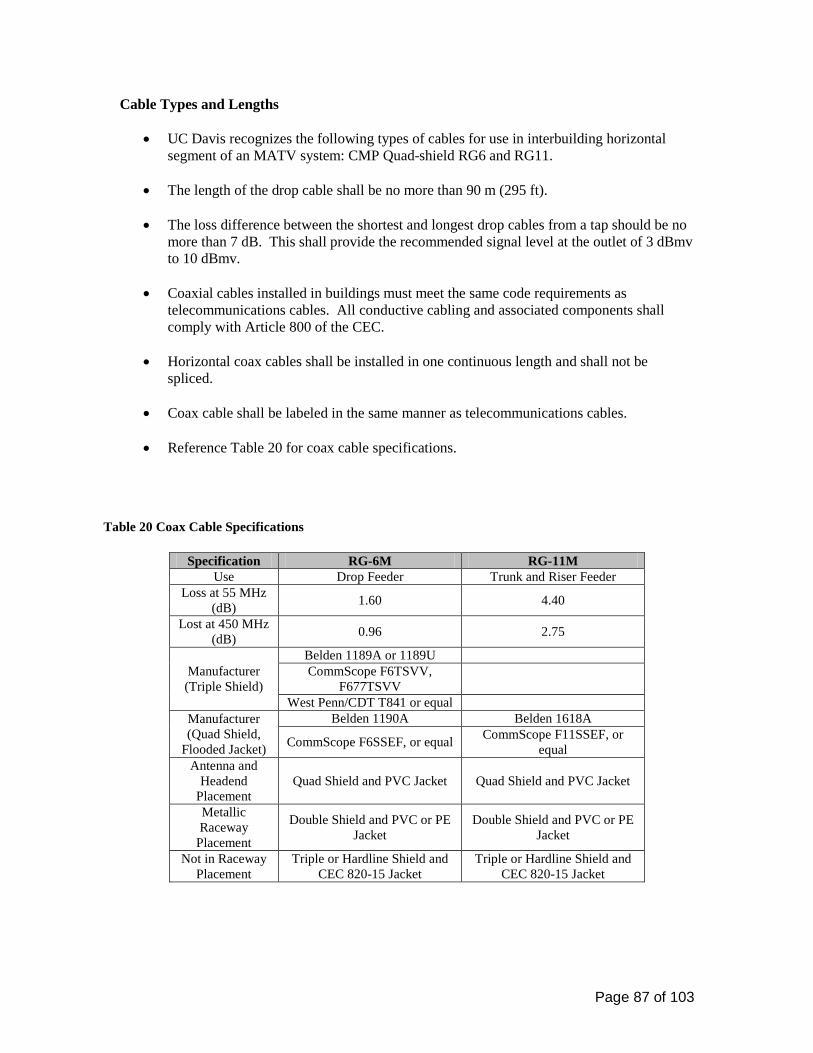
Page 87 of 103
Cable Types and Lengths
• UC Davis recognizes the following types of cables for use in interbuilding horizontal segment of an MATV system: CMP Quad-shield RG6 and RG11.
• The length of the drop cable shall be no more than 90 m (295 ft).
• The loss difference between the shortest and longest drop cables from a tap should be no
more than 7 dB. This shall provide the recommended signal level at the outlet of 3 dBmv to 10 dBmv.
• Coaxial cables installed in buildings must meet the same code requirements as
telecommunications cables. All conductive cabling and associated components shall comply with Article 800 of the CEC.
• Horizontal coax cables shall be installed in one continuous length and shall not be
spliced.
• Coax cable shall be labeled in the same manner as telecommunications cables.
• Reference Table 20 for coax cable specifications.
Table 20 Coax Cable Specifications
Specification RG-6M RG-11M
Use Drop Feeder Trunk and Riser Feeder Loss at 55 MHz
(dB) 1.60 4.40
Lost at 450 MHz (dB) 0.96 2.75
Manufacturer (Triple Shield)
Belden 1189A or 1189U CommScope F6TSVV,
F677TSVV
West Penn/CDT T841 or equal Manufacturer (Quad Shield,
Flooded Jacket)
Belden 1190A Belden 1618A
CommScope F6SSEF, or equal CommScope F11SSEF, or equal
Antenna and Headend
Placement Quad Shield and PVC Jacket Quad Shield and PVC Jacket
Metallic Raceway
Placement
Double Shield and PVC or PE Jacket
Double Shield and PVC or PE Jacket
Not in Raceway Placement
Triple or Hardline Shield and CEC 820-15 Jacket
Triple or Hardline Shield and CEC 820-15 Jacket
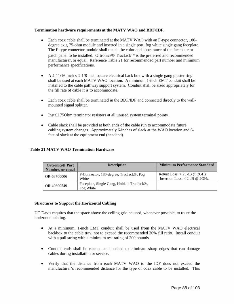
Page 88 of 103
Termination hardware requirements at the MATV WAO and BDF/IDF.
• Each coax cable shall be terminated at the MATV WAO with an F-type connector, 180-degree exit, 75-ohm module and inserted in a single port, fog white single gang faceplate. The F-type connector module shall match the color and appearance of the faceplate or patch panel to be installed. Ortronics TracJack is the preferred and recommended manufacturer, or equal. Reference Table 21 for recommended part number and minimum performance specifications.
• A 4-11/16 inch × 2 1/8-inch square electrical back box with a single gang plaster ring
shall be used at each MATV WAO location. A minimum 1-inch EMT conduit shall be installed to the cable pathway support system. Conduit shall be sized appropriately for the fill rate of cable it is to accommodate.
• Each coax cable shall be terminated in the BDF/IDF and connected directly to the wall-
mounted signal splitter.
• Install 75Ohm terminator resistors at all unused system terminal points.
• Cable slack shall be provided at both ends of the cable run to accommodate future cabling system changes. Approximately 6-inches of slack at the WAO location and 6-feet of slack at the equipment end (headend).
Table 21 MATV WAO Termination Hardware
Ortronics Part Number, or equal
Description Minimum Performance Standard
OR-63700006 F-Connector, 180-degree, TracJack, Fog White
Return Loss: > 25 dB @ 2GHz Insertion Loss: < 2 dB @ 2GHz
OR-40300549 Faceplate, Single Gang, Holds 1 TracJack, Fog White
Structures to Support the Horizontal Cabling UC Davis requires that the space above the ceiling grid be used, whenever possible, to route the horizontal cabling.
• At a minimum, 1-inch EMT conduit shall be used from the MATV WAO electrical backbox to the cable tray, not to exceed the recommended 30% fill ratio. Install conduit with a pull string with a minimum test rating of 200 pounds.
• Conduit ends shall be reamed and bushed to eliminate sharp edges that can damage
cables during installation or service.
• Verify that the distance from each MATV WAO to the IDF does not exceed the manufacturer’s recommended distance for the type of coax cable to be installed. This

Page 89 of 103
distance shall include the planned cable path as well as any vertical transitions and maintenance slack at the termination points.
• Conduits shall be appropriately firestopped in accordance with TIA/EIA 569-B, Annex A, and any/all local fire codes. All firestop installations shall be labeled in accordance with TIA/EIA 606-A.
Broadband Distribution Equipment The following is a list of broadband distribution equipment installed on the UC Davis campus. Broadband indoor distribution amplifier, bi-directional, 1000 MHz Performance, Forward Path,
• Bandwidth: 49-1000 MHz, • Flat Gain: Not less than 32 dB
Performance, Reverse Path:
• Bandwidth: 5-36 MHz • Flat Gain: Not less than 24 dB
Cross modulation, composite triple beat and hum modulation each at least 3 dB better than system specifications herein.
• Manufacturer: Blonder-Tongue BIDA100A with on-board active return amplifiers, scientific-Atlanta, Broadband Engineering, Triple Crown or equal
Blonder Tongue Broadband passive devices, or equal
• Blonder-Tongue SRT Series • Grounding Block: • Blonder-Tongue FA Series, • Blonder-Tongue SXRS • Blonder-Tongue BTF-TP 4670 • F-type Connectors (to match type of cable):
Assigning the MATV NAM numbers
• The Consultant shall obtain MATV NAM numbers from the CR Project Engineer. Contact the A&E project manager for contact information.
• All additional MATV NAM numbers shall be obtained only from CR. MATV NAM
numbers shall not be duplicated. The project consultant or design professional is responsible for the issuing of accurate MATV NAM numbers and drawings.
• After MATV NAM numbers have been assigned to the floor plans, the consultant shall
complete the MATV NAM Matrices. MATV NAM Matrices are to be completed at the

Page 90 of 103
beginning of Construction Document (CD) preparation. A hardcopy of MATV NAM Matrices shall be provided to the A&E Project Manager and a MS-Excel 2000 spreadsheet file to be provided to Communications Resources.
The consultant shall ensure that specifications are placed in the contract documents that inform the cabling contractor regarding use and maintenance of the MATV NAM Matrices for the project. Cable Testing Procedures Four factors that must be considered when calculating losses in a network are cable loss, splitter loss, insertion loss and isolation loss. A properly designed system shall provide a signal level between 3 dBmv and 10 dBmv to every MATV WAO on all channels.
Test and report on each intermediate cabling segment, including BDF/IDF to MATV WAO. Test each end-to-end cable link.
The tests should ensure that the system and its components meet the specifications for:
• Distortion. • Signal Uniformity • Signal-to-Noise Ratio (SNR) • Signal Ingress • Hum Modulation
Performance Requirements The MATV system shall meet the following performance requirements:
1. Compliance with Title 47, Code of Federal Regulations, Part 76, Cable Television Rules
and Regulations.
2. Provide interference-free distribution of any of the scheduled UC Davis channels and allow for future distribution of internally generated forward and reverse channels.
3. Provide CATV compatible adjacent channel operation with bandwidth to at least 1000
MHz. Bandwidth of amplifiers shall be from 49 MHz to 1000 MHz in the forward direction, unless otherwise indicated.
4. Passive elements shall permit upstream (reverse channel) transmission of 5 MHz to 36
MHz sub-low band VHF television channels from the Headend to any MATV WAO.
5. Output levels of +6 to +12 dBmv from 54 MHz to 450 MHz nominal. +3 dBmv at output levels above 450 MHz. Tap off output level shall not exceed +15dBmV.
Page 91 of 103
6. Signal level from any channel to any adjacent channel shall not vary more than 2 dB at the tap off location.
7. Long term variations in amplitude shall not exceed 3 dB.
8. Amplitude response within any channel shall not exceed +1.0 dB. 9. Amplitude response for the entire spectrum sector shall not exceed +/- 2 dB.
10. Visual carrier to noise ration shall not be less than 50 dB.
11. Composite triple beat ratio shall not be less than 55 dB.
12. Cross modulation ratio shall not be less then 57 dB.
13. Visual carrier to hum modulation ratio shall not be less than 63 dB.
14. Visual carrier to reflections ratio shall not be less than 46 dB.

Page 92 of 103
800 MHz IN-BUILDING RADIO SYSTEMS 27 32 00 The Design Process This chapter establishes the policies and procedures regarding 800 MHz in-building amplified radio systems required in new campus buildings. General Radio Communications Coverage All buildings are required to support radio communications from the local public safety entities (Campus Fire, Police etc.) This section provides standards and guidance in support of the 800 MHz in-building radio communications systems. All capitol building projects exceeding 5,000 square feet (to include multi-level structures) are required to install, at a minimum, an amplification system on the first floor and basement. Additional performance coverage tests shall be performed before and during the construction phase to determine if additional in-building amplification is required for adequate coverage throughout the entire building. Evaluation Process The evaluation process for determining the need for additional in-building amplification shall be conducted in a minimum of two phases: Pre-construction and construction.
• Pre-construction Phase: Before the construction of the new building, basic information shall be gathered to begin the process of determining the type and actual implementation of an augmented radio system. In most cases, the following information shall be obtained to properly design and costs estimate an in-building radio system.
• Construction Phase: As the construction progresses, refinements to the initial multi floor
system estimate shall be made to ensure that the proposed IBAS will provide adequate coverage and to re-evaluate the impact on existing structures. A re-evaluation of the initial specifications shall help to fine-tune the proposed system size.
Design Requirement: A 4-inch conduit shall be dedicated from the equipment/telecommunications room (ER/TR), on the highest building level, to a sealed junction box on the roof of the building for use as an antenna access point. This conduit shall be grounded using a path other than the telecommunications ground provided in the ER/TR. The assessment, design and cost shall be performed by an IET-Communications Resources Project Manager. Please contact for more information.
Page 93 of 103
APPENDIX B Reference Materials Following is a list of reference material on telecommunications infrastructure: ANSI/TIA/EIA-526-7 (June 2003), Measurement of Optical Power Loss of Installed Single-mode Fiber Cable Plant. The intent of this procedure is to ensure that meaningful data describing the optical loss performance of installed single-mode cable plant can be obtained. Includes passive components, does not include active components. ANSI/TIA/EIA-526-14A (August 2003), Optical Power Loss Measurements of Installed Multimode Fiber Cable Plant. The intent of this procedure is to ensure that meaningful data describing the optical loss performance of installed multimode cable plant can be obtained. Includes passive components, does not include active components. ANSI/TIA/EIA-568-B-1 (May 2001), Commercial Building Telecommunications Cabling Standard, Part 1: General Requirements. This standard specifies minimum requirements for telecommunications cabling within a commercial building and between buildings in a campus environment. It specifies cabling requirements, cabling distances, telecommunications outlet/connector configurations, and a recommended topology.
• TIA/EIA-568-B.1-1 Addendum 1 – Minimum 4-Pair UTP and ScTP Patch Cable Bend Radius - (May 2001)
• TIA/EIA-568-B.1-2 Addendum 2 – Grounding and Bonding Requirements for Screened Balanced Twisted-Pair Horizontal Cabling - (February 2003)
• TIA/EIA-568-B.1-3 Addendum 3 – Supportable Distances and Channel Attenuation for Optical Fiber Applications by Fiber Type - (February 2003)
• TIA/EIA-568-B.1-4 Addendum 4 – Recognition of Category 6 and 850 nm Laser Optimized 50/125 μm Multimode Optical Fiber Cabling - (February 2003)
• TIA/EIA-568-B.1-5 Addendum 5 – Telecommunications Cabling for Telecommunications Enclosures – (March 2004)
• TIA/EIA-568-B.1-7 Addendum 7 - Guidelines for Maintaining Polarity Using Array Connectors – (January 2006)
TIA/EIA-568-B.2 Commercial Building Telecommunications Cabling Standard Part 2: Balanced Twisted-Pair Cabling Components - (December 2003)
• TIA/EIA-568-B.2-1 Addendum 1 – Transmission Performance Specifications for 4-Pair 100 ohm Category 6 Cabling - (June 2002)
• TIA/EIA-568-B.2-2 Addendum 2 – Revision of Sub-clauses - (December 2001) • TIA/EIA-568-B.2-3 Addendum 3 – Additional Considerations for Insertion Loss &
Return Loss Pass/Fail Determination - (March 2002) • TIA/EIA-568-B.2-4 Addendum 4 – Solderless Connection Reliability Requirements for
Copper Connecting Hardware - (June 2002) • TIA/EIA-568-B.2-5 Addendum 5 – Corrections to TIA/EIA-568-B.2 – (January 2003) • TIA/EIA-568-B.2-6 Addendum 6 – Category 6 Related Component Test Procedures –
(December 2003) • TIA/EIA-568-B.2-11 Addendum 11 - Specification of 4-Pair UTP and SCTP Cabling –
(December 2005)

Page 94 of 103
TIA/EIA-568-3 Optical Fiber Cabling Components Standard - (April 2002)
• TIA/EIA-568-3.1 Addendum 1 – Additional Transmission Performance Specifications for 50/125 μm Optical Fiber Cables – (April 2002)
ANSI/EIA/TIA-569-B (November 2004), Commercial Building Telecommunications Pathways and Spaces, describes design and construction practices for pathways and spaces to support telecommunications media and equipment within and between buildings. Standards are for the design of horizontal and work area pathways, building entrance facilities, telecommunications closets and equipment rooms.
ANSI/TIA/EIA-570-B -2004, Residential Telecommunications Cabling Standard. It standardizes requirements for residential telecommunications cabling based on the facilities that are necessary for existing and emerging telecommunications services including security, home audio and building control cabling systems. ANSI/TIA/EIA–587 (October 1996), Fiber Optic Graphic Symbols. ANSI/TIA/EIA-598-C-2005, Optical Fiber Cable Color Coding defines the recommended identification scheme or system for individual fibers, fiber units or groups of fiber units within a cable structure. ANSI/TIA/EIA-606-A (May 2002), Administration Standard for the Telecommunications Infrastructure of Commercial Buildings. This standard specifies administration systems for commercial telecommunications infrastructure with choices of classes of administration for maintaining telecommunications infrastructure including; existing, renovated and new buildings. ANSI-J-STD-607-A (October 2002), Commercial Building Grounding (Earthing) and Bonding Requirements for Telecommunications. The purpose of this standard is to enable the planning, design, and installation of telecommunications grounding and bonding systems within a building with or without prior knowledge of the telecommunications systems that will subsequently be installed. TIA-758-A (September 2004), Customer-Owned Outside Plant Telecommunications Infrastructure Standard This document provides requirements used in the design of the telecommunication pathways and spaces and the cabling installed between buildings or points in a customer-owned campus environment.
TIA-Telecommunications Systems Bulletin (TSB) 140 (February 2004), Additional Guidelines for Field-Testing Length, Loss and Polarity of Optical Fiber Cabling Systems. This TSB describes field-testing of length, optical attenuation and polarity in optical fiber cabling using an optical loss test set (OLTS), optical time domain reflectometer (OTDR) and a visible light source such as a visual fault locator (VFL). The purpose of this document is to clarify, not replace, ANSI/TIA/EIA-526-7 and ANSI/TIA/EIA-526-14A. CALIFORNIA ELECTRIC CODE (CEC 2001), CODE OF REGULATIONS, TITLE 24, PART 3. This document incorporates, by adoption, the 1999 edition of the National Electrical Code® of the National Fire Protection Association with the California amendments. CALIFORNIA BUILDING CODE (CBC 2001), CODE OF REGULATIONS, TITLE 24, PART 2, VOLUME 1 AND 2. This document incorporates, by adoption, the 1997 edition of the
Page 95 of 103
uniform Building Code® of the International Conference of Building Officials with necessary California amendments. ANSI/NFPA-70: National Electrical Code® (NEC 2005). A set of codes governing items such as voltage limits, transmission media conductor size, over voltage protection requirements, fire resistance of cables and cabling methods. It is important to check with local governing bodies to determine if their codes supersede the NEC articles. IEEE National Electrical Safety Code® (NESC 2002). This standard covers basic provisions for safeguarding of persons from hazards arising from the installation, operation or maintenance of conductors and equipment in electric supply stations and overhead and underground electric supply and communication lines. It also includes work rules for the construction, maintenance and operation of electric supply and communication lines and equipment. Underwriters Laboratories (UL), LAN Cable Certification Program. Test products to verify that performance meets or exceeds industry standards. The UL tests the electrical shock, flame spread and smoke production characteristics of cables. The UL also tests cables for transmission properties. Building Industry Consulting Service International (BICSI) Telecommunications Distribution Methods Manual (TDMM), 11th Edition.
BICSI Customer-Owned Outside Plant (CO-OSP) Design Manual, 4th Edition BICSI Network Design Reference Manual, 6th Edition. BICSI Wireless Design Reference Manual, 3rd Edition. California Public Utilities Commission (CPUC) General Orders 95 and 128.
Page 96 of 103
Appendix C Definitions Access floor: A system consisting of completely removable and interchangeable floor panels that are supported on adjustable pedestals or stringers (or both) to allow access to the area beneath. Administration: The method for labeling, identification, documentation and usage needed to implement moves, additions and changes of the telecommunications infrastructure. Aerial cable: Telecommunications cable installed on aerial supporting structures such as poles, sides of buildings and other structures. Alternate entrance: A supplementary entrance facility into a building using a different routing to provide diversity of service and for assurance of service continuity. Architectural structures: Walls, floors, floor/ceilings and roof/ceilings that are load bearing. Area Distribution Frame (ADF): A Telecommunications Space (Equipment or Telecommunications Room) that houses digital loop carrier, network switching and video electronic equipment, as well as, outside plant cable termination hardware for a specific serving area on the UC Davis campus. Backbone: A facility (e.g., pathway, cable or conductors) between telecommunications closets or floor. Bonding: The permanent joining of metallic parts to form an electrically conductive path that will ensure electrical continuity and the capacity to conduct safely any current likely to be imposed. (TIA) Building core: A three-dimensional space permeating one or more floors of the building and used for the extension and distribution of utility services (e.g., elevators, washrooms, stairwells, mechanical and electrical systems and telecommunications) throughout the building. Building Distribution Frame (BDF): A Telecommunications Space that houses digital loop carrier, network switches, video electronic equipment and cable termination hardware for the building in which the BDF room is located. In addition, a BDF may also serve a number of smaller Intermediate Distribution Frames (IDF’s) located within the same building and/or IDF’s located outside of the building and within the immediate area. Buried cable: A cable installed under the surface of the ground in such a manner, that it cannot be removed without disturbing the soil. Cabinet (telecommunications): A container that may enclose connection devices, terminations, apparatus, wiring and equipment. (TIA) Cable: An assembly of one or more conductors or optical fibers, within an enveloping sheath, constructed so as to permit use of the conductors singly or in groups. Cabling: A combination of all cables, wire, cords and connecting hardware.
Page 97 of 103
Campus: The buildings and grounds having legal contiguous interconnection. Ceiling distribution system: A distribution system that utilizes the space between a suspended or false ceiling and the structural surface above. Closet (telecommunications): A recognized location of the cross-connect between the backbone and horizontal facilities. This term has been replaced with the term Telecommunications Room Conduit: A raceway of circular cross-section. Consolidation point: A location for interconnection between horizontal cables extending from building pathways and horizontal cables extending into furniture pathways. Cross-connect: A frame or space that enables the termination of cable elements and their interconnection or cross-connection of these cable elements, or both, by the use of a patch cord or jumper. Cross-connection: A connection scheme between cable runs, subsystems and equipment using patch cords or jumpers to attach to connecting hardware on each end. Device (as related to a work area): An item such as a telephone, personal computer or a graphic or video terminal. Distribution frame: A structure with terminations for connecting the cabling of a facility in such a manner that interconnections or cross-connections may be readily made. Distribution terminals: The entrance facilities and the equipment rooms within or between buildings. Emergency power: A stand-alone secondary electrical supply source not dependent upon the primary electrical source. End user: The owner or user of the premises cabling system. Entrance point (telecommunications): The point of emergence of telecommunications conductors through an exterior wall, a concrete floor slab or from a rigid metal or intermediate metal conduit. Entrance room or space (telecommunications): A space, wall or location in which public and private service cables, to include antennae, enter a building and continue to the equipment or telecommunications room or space. Equipment room (telecommunications): A centralized space for telecommunications equipment that serves the occupants of the building. Fiber to the desktop: The fiber optic cabling between and including the telecommunications outlet/connector and the horizontal cross-connect. Fire stop: A material, device, or assembly of parts installed in a cable pathway at a fire-rated wall or floor to prevent passage of flame, smoke or gases through the rated barrier (e.g., between cubicles or separated rooms or spaces), fire stop seals: See fire stop system.
Page 98 of 103
Fire stop system: A specific construction consisting of the material(s) (fire stop penetration seals) that fill the opening in the wall or floor assembly and any items that penetrate the wall or floor, such as cables, cable trays, conduit, ducts, pipes and any termination devices, such as electrical outlet boxes, along with their means of support. Fire stopping: The process of installing specialty materials into penetrations in fire-rated barriers to reestablish the integrity of the barrier. Floor slab: That part of a reinforced concrete floor which is carried on beams below, Ground: A conducting connection, whether intentional or accidental, between an electrical circuit (e.g., telecommunications) or equipment and the earth or to some conducting body that serves in place of earth. Grounding conductor: A conductor used to connect the grounding electrode to the building’s main grounding bus bar. Grounding electrode: A conductor, usually a rod, pipe or plate (or group of conductors) in direct contact with the earth for the purpose of providing a low-impedance connection to the earth. Hand hole: A structure similar to a small maintenance hole in which it is expected that a person cannot enter to perform work. Header duct; trench, feeder duct: A raceway of rectangular cross-section placed within the floor to tie distribution duct(s) or cell@) to the telecommunications closet. Home runs: A pathway or cable between two locations without a point of access in between. Horizontal cabling: The cabling between and including the telecommunications outlet/connector and the horizontal cross-connect. Hybrid cable: An assembly of two or more cables, of the same or different types or categories, covered by one overall sheath. Infrastructure (telecommunications): A collection of those telecommunications components, excluding equipment, that together provides the basic support for the distribution of all information within a building or campus. Innerduct: Typically, a nonmetallic pathway within a pathway. Also known as sub duct. Interconnection: A connection scheme that employs connecting hardware for the direct connection of a cable to another cable without a patch cord or jumper. Intermediate cross-connect: A cross-connect between first level and second level backbone cabling. Intermediate Distribution Frame (IDF): A Telecommunications Space (Telecommunications Room) that houses network switching, video electronic equipment, as well as, riser and horizontal cable termination hardware for the building in which the IDF room is located.
Page 99 of 103
Jumper: An assembly of twisted pairs without connectors, used to join telecommunications circuits/links at the cross-connect. Main cross-connect: A cross-connect for first level backbone cables, entrance cables and equipment cables. Main distribution frame: A Telecommunications Space that houses the campus phone switch, network equipment, video electronic equipment and copper and fiber cable terminations for connecting the cabling of a facility in such a manner that interconnections or cross-connections may be readily made for the campus. The MDF serves the ADF’s and BDF’s of the campus Maintenance hole (telecommunications manhole): A vault located in the ground or earth as part of an underground duct system and used to facilitate placing, connectorization and maintenance of cables, in which it is expected that a person will enter to perform work. Membrane penetration: An opening through only one surface or side of the barrier. Minimum Point of Entry (MPOE) The MPOE is the point at which the network facilities provided by the service provider or utility stop, and the property owner’s facilities begin. It also referred to as the Minimum Point of Presence (MPOP). Multi-user telecommunications outlet assembly (MUTOA): A grouping in one location of several telecommunications work area outlets. Network Access Modules (NAM): A UC Davis term to identify a voice, data, FTTD and/or video jack or module. Open office: A floor space division provided by furniture, moveable partitions or other means instead of by building walls. Optical fiber cable: Cable made up of one or more strands of glass consisting of a central core and outer cladding (optical fibers), strength members, and an outer jacket. Outlet box (telecommunications): A metallic or nonmetallic box mounted within a wall, floor or ceiling and used to hold telecommunications outlets/connectors or transition devices. Outlet/connector (telecommunications): See NAM. Patch cord: A length of cable with connectors on one or both ends used to join telecommunications circuits at the cross-connect. Pathway: A facility for the placement of telecommunications cable. Penetration: An opening in a fire-rated barrier. Plenum: A compartment or chamber to which one or more air ducts are connected and that forms part of the air distribution system. Poke-thru system: Penetrations through the fire resistive floor structure to permit the installation of horizontal telecommunications cables.

Page 100 of 103
Pull cord or pull wire: A cord or wire placed within a raceway and used to pull wire and cable through the raceway. Raceway: Any enclosed channel designed-for holding wires or cables. Service loop: A surplus of cable, typically located at or near the point of termination to facilitate potential future changes. Slab on grade: Concrete floor placed directly on soil, without basement or crawlspace. Sleeve: An opening, usually circular, through the wall, ceiling or floor to allow the passage of cables. Slot: An opening through a wall, floor, or ceiling, usually rectangular, to allow the passage of cables. Space (telecommunications): An area used for housing the installation and termination of telecommunications equipment and cable, e.g., equipment and telecommunications room, work areas and maintenance holes/hand holes. Splice: A joining of conductors, generally meant to be permanent, generally from separate sheaths. Splice box: A box, located in a pathway run, intended to house a cable splice. Suspended ceiling: A ceiling that creates an area or space between ceiling material and the structure above. Telecommunications: Any transmission, emission, and reception of signs, signals, writings, images, and sounds, that is information of any nature by cable, radio, optical or other electromagnetic systems, Telecommunications space: See space (telecommunications). Terminal: 1. A point at which information may enter or leave a telecommunications network. 2. A device by means of which wires may be connected to each other.
Termination hardware: This term is outdated. See connecting hardware. Through penetration: A continuous opening that passes through both surfaces of a fire-rated barrier. Topology: The physical or logical arrangement of a telecommunications system. Under floor raceway: A pathway placed within the floor and from which wires and cables emerge to a specific floor area. Usable floor space: Floor space, which is capable of being used as a work area. Work Area Outlet (WAO): A wall-mounted or surface-mounted faceplate or box containing a voice, data, FTTD and/or video NAM or any combination thereof.
Page 101 of 103
Abbreviations A or AMP ampere ac alternating current ADA Americans with Disabilities Act ADF Area Distribution Frame A&E Architects & Engineers AFF above finished floor AHJ authority having jurisdiction AHU air handling unit ALPETH aluminum polyethylene ANSI American National Standards Institute AP access point ASTM American Society for Testing and Materials AWG American wire gauge B or Bur buried BAS building automation systems BC bonding conductor BDF Building Distribution Frame BEF building entrance facility BICSI ® Building Industry Consulting Service International BMS Building Management System Btu British thermal unit CA cable CAD computer- aided design CATV community antenna television (cable television) CBC coupled bonding conductor CBC® California Building Code CEC® California Electrical Code CCTV closed circuit television CD construction documents CEV controlled environment vault CF cellular floor ckt circuit CM construction manager CMP communications plenum cable CMR communications riser cable CO central office coax coaxial cable CP consolidation point CPE customer provided equipment CSI Construction Specifications Institute CT cable tray DB direct- buried DB ductbank DD design development DP demarcation point

Page 102 of 103
EF entrance facility EIA Electronic Industries Alliance EM electromagnetic EMI electromagnetic interference EMS energy management system EMT electrical metallic tubing ENT electrical non-metallic tubing ER equipment room °F degree Fahrenheit FA fire alarm FACP fire alarm control panel FEXT far-end crosstalk FTTD fiber to the desktop Gb/s gigabit per second gnd ground h hour HC horizontal cross-connect HH handhole HVAC heating, ventilating, and air-conditioning Hz hertz IC intermediate cross-connect ID inside diameter IDC insulation displacement connector IDF Intermediate Distribution Frame IEEE ® Institute of Electrical and Electronics Engineers, Inc. IG isolated ground ISP inside plant LAN local area network lbf pound-force LEC local exchange carrier (now service provider [SP]) MAC move, add or change MB megabyte Mb/s megabit per second MC main cross- connect MDF main distribution frame MH maintenance hole MHz megahertz MM multimode MUTO multi-user telecommunications outlet MUTOA multi-user telecommunications outlet assembly N newton NAM Network Access Module NEC ® National Electrical Code ® NEMA ® National Electrical Manufacturers Association ®

Page 103 of 103
NFPA ® National Fire Protection Association ® NIC network interface card OD outside diameter Ohm Ω OSP outside plant OTDR optical time domain reflectometer PB pull box PBX private branch exchange PE polyethylene pr pair PVC polyvinyl chloride RCDD ® Registered Communications Distribution Designer RUS Rural Utilities Services RFI request for information RFP request for proposal RFQ request for quote RNC rigid non-metallic cable ScTP screened twisted- pair SD schematic design SFF small form factor SM single-mode STALPETH steel, aluminum, polyethylene STP shielded twisted- pair TB terminal block TBB telecommunications bonding backbone TBBIBC telecommunications bonding backbone interconnecting bonding conductor TC telecommunications closet (see telecommunications room) TDD telecommunications device for the deaf TEF telecommunications entrance facility TEL telephone TGB telecommunications grounding busbar TIA Telecommunications Industry Association TMGB telecommunications main grounding busbar TR telecommunications room TS telecommunications spaces TTB telephone terminal board TTY teletypewriter/text telephone UBC uniform building code UG underground UL ® Underwriters Laboratories Inc. ® UPS uninterruptible power supply WA work area WAN wide area network WAO work area outlet