Diversity-lock phase demodulator - NASA
19
d NASA TN D-3342 / ~ DIVERSITY-LOCK PHASE DEMODULATOR by V. J. DiLosa
Transcript of Diversity-lock phase demodulator - NASA

d
N A S A TN D-3342 / ~
DIVERSITY-LOCK PHASE DEMODULATOR
by V. J. DiLosa

TECH LIBRARY KAFB, NM
OL30b25
NASA TN 0-3342
DIVERSITY -LOCK PHASE DEMODULATOR
By V. J. DiLosa
Goddard Space Flight Center Greenbelt , Md.
NATIONAL AERONAUTICS AND SPACE ADMINISTRATION
For sale by the Clearinghouse for Federal Scientific and Technical Information Springfield, Virginia 22151 - Price $0.25

ABSTRACT
A synchronous demodulator utilizing the unique principle of diversity-lock has been developed for tracking and de- modulating orthogonally polarized signals transmitted from satellites. For the first time, the well known principles of pre-detection diversity combining are applied to the phase- lock operation of a demodulator. Consequently, with inde- pendently fading signals the phase-lock performance is extended beyond present day carr ier tracking demodulators. This unique feature is achieved by using three phase-lock tracking filters, one independent (primary loop) for tracking the doppler signal and two dependent (auxiliary loops) which provide signal coherence and weighting for combining. Since both auxiliary are automatically controlled by the primary loop, only the primary loop requires operating controls. This principle can be applied to a multi channel system with full diversity improvement and with essentially the same degree of operational simplicity as a two channel system.
i i
CONTENTS
Abstract . . . . . . . . . . . . . . . . . . . . . . . . . . . . . . . i
INTRODUCTION . . . . . . . . . . . . . . . . . . . . . . . . . 1
WEIGHTING FUNCTION . . . . . . . . . . . . . . . . . . . . 4
PHASE LOCK ANALYSIS . . . . . . . . . . . . . . . . . . . 6
DEMODULATOR . . . . . . . . . . . . . . . . . . . . . . . . . 7
CONCLUDING REMARKS . . . . . . . . . . . . . . . . . . . 9
ACKNOWLEDGMENT . . . . . . . . . . . . . . . . . . . . . . 9
References . . . . . . . . . . . . . . . . . . . . . . . . . . . . . 9
Appendix A-Diversity-Lock Phase Demodulator Performance Specifications . . . . . . . . . 11
iii
.

DIVERSITY-LOCK PHASE DEMODULATOR
by V. J. DiLosa
Goddard Space Flight Center
INTRODUCTION
During the past five years a number of small scientific satellites and space probes have been launched that used either pulsed-f requency modulation (PFM) or frequency modulation of a sub- ca r r i e r oscillator to phase modulate the main telemetry carr ier . This type of telemetry has a data bandwidth several orders of magnitude smaller than the receiver noise bandwidth. Consequently the signal-to-noise ratio (S/N) at the demodulator input is often below 0 db. Low level signals buried in noise are demodulated by a synchronous demodulator to preserve the signal-to-noise ratio.
Signals transmitted by means of amplitude modulation or narrow-band phase modulation a r e equally capable of synchronous demodulation. However, phase modulation has an advantage in that the transmitter design is more compact, light and efficient.
Since phase modulation is the preferred form of transmission, it is appropriate to seek an op- timum synchronous phase demodulator. The first phase demodulator used at the STADAN* ground stations was a doppler phase-lock tracking filter modified to include both synchronous amplitude and synchronous phase demodulators. Although this filter operated at a relatively low ca r r i e r frequency, hence low information bandwidths, it w a s used successfully to demodulate data from satellites such as Explorer X, Explorer XI, and Explorer XIV. To supersede this tracking filter a phase demodulator/combiner was developed to operate at a higher ca r r i e r frequency and with a video data bandwidth of 150 kc. This demodulator is presently in use at the STADAN stations.
The introduction of high-bit-rate pulse-code modulation (PCM) and the continued use of PFM/PM in satellite telemetry necessitated the development of a new diversity-telemetry receiver to pro- vide the STADAN stations with envelope detection and frequency demodulation, and also with op- timum post-detection combining. To provide this receiver with synchronous demodulation an advanced phase demodulator was conceived and developed. This demodulator provides STADAN with the new principle of diversity-lock, e.g., phase locking to an optimally combined signal. It is based on well known principles of linear-diversity combiners and phase-lock tracking filters.
*Satellite Tracking and Data Acquisition Network.
1

To illustrate the more significant advantages of the diversity-lock demodulator it might be appropriate to consider briefly the operation of the existing Electrac phase demodulator. The latter was developed primarily to provide the Bendix "Mod. I" telemetry receiver with coherent demodulation and optimum combining for the data channels only; thus the diversity improvement was not realized with respect to the phase-lock operation. Two independent phase-lock tracking filters (PLTF) are used to make the signals phase-coherent and to generate the proper weighting function prior t o combining. Obviously, with independently fading signals resulting from polariza- tion diversity, a channel that drops lock will not necessarily re-lock when the signal regains strength. Under these conditions manual re-locking of each P L T F would be required as the signals fade in and out. Thus, although the Electrac demodulator performs as expected with respect to the data channels, there is an obvious disadvantage with respect to its phase-lock performance and operational simplicity. Both phase-lock performance and simplicity of operation can be greatly improved by utilizing the principle of diversity-lock.
The new diversity-lock demodulator (Figure 1) realizes the full diversity improvement in the phase lock operation as well as in the demodulated signals. Consequently, the probability of the diversity PLTF losing lock is less than the corresponding probability for the stronger channel alone. This new feature not only yields improved performance, but requires only one set of con- trols to lock all three phase-lock loops. Since the diversity P L T F is under the control of the optimally combined signal, it will continue to track the signal even though either polarization channel may independently fade below the level required to maintain phase-lock. As long as the main loop is tracking, the faded signal upon recovering signal strength will automatically re-lock; thus the effects of fading are removed from the data channel as well as from the phase-lock channel. Since the lock of the auxiliary phase-lock loops (PLL's) depends on the lock of the di- versity PLTF, one tuning control is required to adjust the frequency setting of the VCO that tracks the doppler shifts. Upon acquisition of the diversity PLTF, the two auxiliary PLL's automatically acquire lock without the aid of an operator. The diversity phase-lock loop, a third order loop, determines the phase-lock sensitivity, while the second order auxiliary PLL's provide phase co- herence and weighting.
Diversity. reception is a technique used in a receiving system whereby independently fading signals received from spacecraft a r e optimized to yield the best possible output signal-to-noise ratio. The maximum output signal-to-noise ratio realizable from a linear maximal-ratio com- biner has been shown by Brennan (Reference 1) to be the sum of the power signal-to-noise ratios f rom both channels. When the signal-to-noise ratios of both channels a r e equal, the average im- provement in the combined signal-to-noise ratio is 3db better than either channel alone. However, to achieve the optimum improvement in output signal-to-noise ratio, the signals from each channel must be made phase coherent prior to combining and must be weighted according to the quality of their signal-to-noise ratios; furthermore, the noise voltages from each channel must be non-correlated.
2

I
REF OD I kc Bw 8, Mc TO OEMODULATOR - I
27.5Mc I
I A I I
I I I
PHASE
19.5Mc v:o [ ATR ~ { D E E C T O R ~ R E F Q w" I I I I I
11.oMc
AllENUATOR
FREQUENCY I METER D.C. AMPL
1 PHASE
DETECTOR DRIVER
vco 38.5 Mc
CORRELATION AMPLIFIER
CORREL-
CONTROL
Idl I COMBINER
D IFFERENCE D.C. AMPL.
ATTENUATOR DRIVER
ATTENUATOR DRIVER
I AGC i I I I METER I
i I I
I vco
I I 19.5 M c
I t 1 I
I t I I I I
8.0Mc 2.0 M ~ B W I 2.OkcBW TO DEMODULATOR- LREF ! I
""s" PHASE
DEMODULATOR
& LOWPASS
DEMODULATOR
OUTPUT REF 0'
L --___----____________ J
Figure 1-Block diagram of diversity-lock demodulator.
w

W El GHTl NG FUN CTl ON
The requirements of optimum weighting a r e established by generating an AGC voltage that is a linear function of input signal level and then using the difference in the respective AGC voltages
to properly control the weighting circuits. The basic AGC circuit (Figure 2) is a fixed resistance R , and a variable resistance
- w
- - - -
e in
Figure 2-Basic AGC attenuator.
From Figure 2 the network attenuation is
R, ,
- eo 1 R l
a - - = e l +iq
Substituting from Equation 1 gives
R, = the AC resistance for zero control voltage,
K, = diode constant,
E = DC control voltage.
Now if
then
-KIE-log(R1/Ro) a = 10
If, in Equation 3, R, Ro and the attenuation a is expressed in db, then
20 l o g a = -20
4

- B
i 1 10
I I
4 I
?s- B/A -
CALCULATED
I 1
.MEASURED
\\ 15 20 25 : 10 5 0 5
5/N POWER RATIO (db)
Figure 3-Signal-to-noise power ratio.
From Equation 4 it is noted that the attenuation expressed in db is a linear function of AGC control voltage E . If both channels have equal gains, the noise voltages into the auxiliary P L L a r e equal; consequently, the AGC voltages a r e a measure of the input signal-to-noise ratios.
Since the AGC voltages a r e linear functions of signal-to-noise ratios, the time-averaged signal and noise power of the two receiving channels can be expressed* by
- 2 Si N? P, = - I (5)
The difference in coherent AGC voltages is used (Figure 3) to control attenuators A, and A, prior to summing the two signals. This dif- ference is expressed by
E = K, ( l O l o g P , ) - K, ( l O l o g P 1 )
The attenuator weighting circuit is the basic circuit shown in Figure 2 and is expressed by Equa- tion 2. Thus,
.~ . 1 A, =
K l E + l 0 p ( R l / R o ) 1 + 10
By substituting Equation 6 into Equation 7 we get
- . 1 A, = - ~ ~ ~ ~ i 0 i o g ~ 1 ~ / ~ 2 2 + l o g ( ~ ~ / ~ ~ ) (8) AGC,
1 f 10 I:
Let
1 (9) Figure 4-Combining and weighting circuit.
K l = ~ O K , and R, = R,, ;
*Kat+, Louis, "DI- Combining System for NASA Mod I Telemetry Receiver,'' January 1962 (unpublished).
5
l -
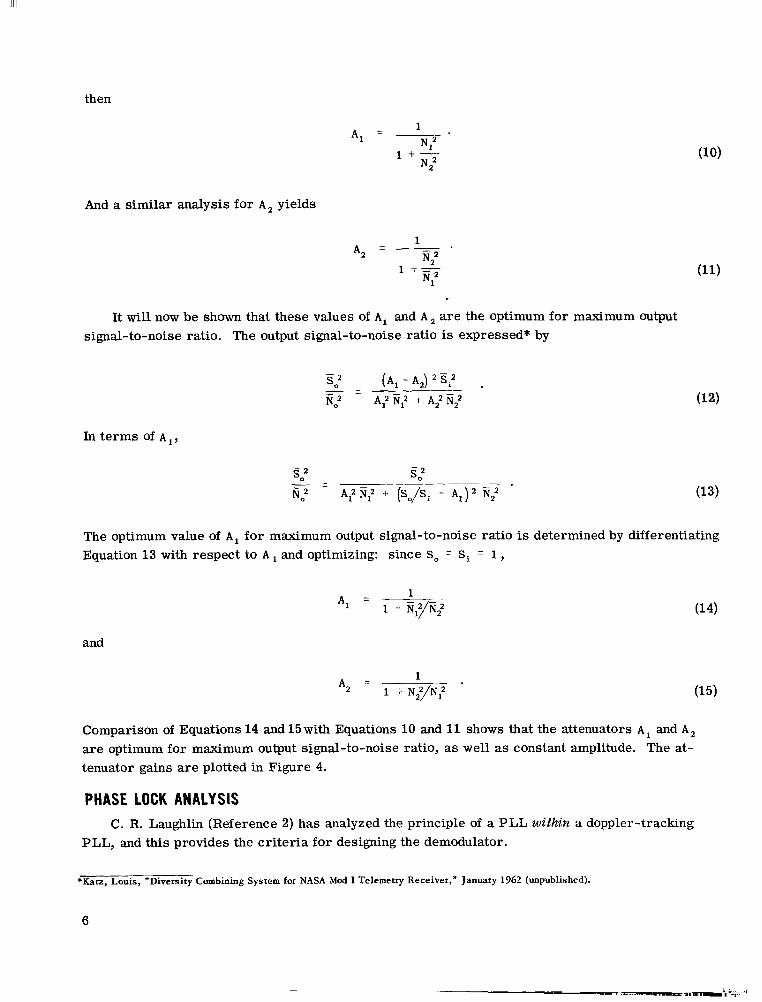
then
And a similar analysis for A, yields
1
1 +r
__=_. N2'
N,2
A, =
It will now be shown that these values of A, and A a r e the optimum for maximum output signal-to-noise ratio. The output signal-to-noise ratio is expressed* by
In te rms of A 1,
- 2 s o
- 2 SO - - fi,2 A: N,2 -t (So/Si - A,), E;
The optimum value of A, for maximum output signal-to-noise ratio is determined by differentiating Equation 13 with respect to A and optimizing: since So = Si = 1,
and
Comparison of Equations 14 and 15 with Equations 10 and 11 shows that the attenuators A , and A,
a r e optimum for maximum output signal-to-noise ratio, as well as constant amplitude. The at- tenuator gains a r e plotted in Figure 4.
PHASE LOCK ANALYSIS C. R. Laughlin (Reference 2) has analyzed the principle of a PLL within a doppler-tracking
PLL, and this provides the cri teria for designing the demodulator.
*Katz, Louis, "Diversity Combining System for NASA Mod I Telemetry Receiver," January 1962 (unpublished).
6

Thus far it has been stated that the signals are made phase coherent by the auxiliary PLL, while the diversity PLL determines the phase-lock sensitivity. Obviously, a PLL within a PLL requires careful design for proper system operation. It has been shown that with a second order loop for both the diversity and auxiliary PLL's, the gain of the diversity loop must be an order of magnitude greater than the auxiliary PLL (Reference 3). This criterion is not critical, but it was easily achieved by making the loop filter bandwidth of the diversity PLL five times that of the auxiliary PLL.
A further design consideration associated with ca r r i e r tracking PLL's is the dynamic range over which they must operate. The phase-lock sensitivity is determined by the heavily filtered output of the phase detector. For a 10 cps tracking noise bandwidth the phase-lock sensitivity is in the order of -155dbm for 20" r m s of phase noise; consequently, for a megacycle of information bandwidth, the noise-to-signal ratio is 44db. The signal plus noise must be amplified at least 160db to give the required phase detector drive; thus, the resulting noise power would exceed the dynamics of the transistor amplifiers as well as the phase detectors. Consequently, narrow-band filters, with 3 kc noise bandwidths, precede the phase detector drivers. Hence the noise-to-signal is reduced to 19db. Even with this noise power reduction, the wideband IF amplifiers and the phase detector drivers must have adequate dynamic range to linearly amplify the signal plus noise.
Careful consideration must be given to the design parameters of the narrow-band crystal f i l ters even though they function solely to limit the noise bandwidth. These filters should be cen- tered at the same frequency and should be phase linear to avoid differential phase shift. Since the data channels are combined independently of the diversity-lock channel, any phase difference between filters results in differential phase shift in the data combiner; and any deviation from phase coherence degrades the expected improvement in output signal-to-noise.
DEMODULATOR
We now consider how to implement these principles in an operational demodulator (Appendix A). The orthogonally polarized signals a r e usually fading, i.e., fluctuating in phase and amplitude as shown (Figure 5). Before they can be combined, both the phase and amplitude disturbances must be resolved. To hold constant the amplitude of the signals to the phase detectors and the com- biner, a coherent AGC is generated by each auxiliary phase detector whose output is a function of the input signal level. If an integrating operational amplifier is employed within the AGC loop, the average signal level change is practically unmeasurable throughout the 40db dynamic operating range. With both signals locked to the common reference oscillator, the IF signals at any point within the auxiliary loops are phase-coherent. Therefore, the signal for the data channel is com- bined separately from the phase-lock signal as shown on the block diagram. With this approach it is more convenient to handle the dynamic range problem associated with the PLL's.
The phase-coherent and weighted signals are so combined that the resultant output is equal to o r better than either channel alone (Figure 5c). It should also be noted that although the average output signal-to-noise ratio varies, the amplitude of the combined signal remains constant. This feature is obtained by the use of the logarithmic attenuator discussed earlier, whose gains a r e plotted in Figure 3.
7

This constant-amplitude combined output signal drives the diversity-lock loop to establish the phase-lock, while the wide-band combined signal drives the demodulator. This data demodu- lator will function as a true phase demodulator o r a synchronous amplitude demodulator by
-0 - -100
3 -110 2 5 -120
Y
0 5; -130h selecting the in-phase or quadrature phase of the
TIME
a - Received signal for channel A.
2 -0 - 9 0 1 load with a 2.0 volt r m s output. Contained in
reference oscillator. Following the demodulator is a video amplifier which will drive a %-ohm
oi -100
F detection filters (Appendix A).
2 -120 (3
the video amplifier module a r e selectable post-
2 -110 _I
The diversity-lock loop is a phase-lock tracking filter with threshold sensitivity de- termined by very narrow effective noise band- widths. Associated with these narrow noise bandwidths a r e small capture ranges. For sig- nal acquisition, the VCO must at all times be within a few cycles of the translated received signal. After phase lock is obtained, the VCO must be able to follow doppler shifts in the re- ceived signal, and with expected doppler shifts in the order of 200 kc the VCO must have a cor- responding deviation. Use of a high deviation VCO to translate the received signal results in a new frequency which is essentially centered within the narrow effective noise bandwidth; thus all doppler shifts are removed. Although
the translated signals a r e centered within these narrow bandwidths, both signals must be made phase-coherent by electronic phase shifters capable of shifting many cycles. These automatic phase shifters are the auxiliary PLL's, each with their own VCO and conversion.
- 130 vl
TIME b - Received signal for channel B.
9 a
5 -110
(3
iL - -100 oi Y
2 5 -120
vl -130
TIME
c - Received signal for combined channels.
Figure %Received signal power determined by measuring the respective AGC voltages.
-9LL Although doppler tracking as well as phase correction can be implemented by converting the
signal once, in this particular demodulator a double conversion was used. A first conversion is required to remove doppler shifts, and a second conversion is required for the auxiliary PLL's.
Since this demodulator is to be used with the 11.0-Mc IF output of the receiver, the latter must be translated via a double conversion. The final IF frequency must be high enough to handle the 2- or 3-Mc R F data bandwidth, while at the same time it is desirable to operate the phase detectors and the VCO's at the lowest possible frequency.
As a result of the double conversion scheme the final IF frequency is centered at some pre- determined frequency; consequently, it is convenient to precede the phase detector drivers with narrow-band filters to band-limit the noise. After bandwidth restraint, the rms noise level is
8

high cnough that a large-signal transistor such as the 2N1506 is used to assure that the signal plus noise is amplified without excessive distortion. For example, if the signal level must be held n t n 0.5 volts rnis for a phase detector sensitivity of 0.5 volt/radian, the noise level will ap- proach 5 volt rnis before the system will lose lock. With the noise level often ten t imes greater than the signal, balanced phase detectors a r e used to minimize any phase detector unbalance in e.\treniely noisy conditions.
The received signals a r e maintained frequency coherent by means of common local oscillators for all conversions. However, the VCO's within the auxiliary PLL a r e independent; hence fre- quency coherence is somewhat imparied. These independent VCO's should be highly stable and should oscillate within a few cycles of one another. As long as this condition is maintained, the final IF frequency in the demodulator will be within the capture range of the auxiliary PLL, and wil l automatically acquire phase-lock. Thus, the IF signal is made frequency and phase-coherent prior to linear combining.
Based on the aforementioned principles, a developmental model of a diversity-lock phase de- modulator was designed and constructed. This dual channel diversity demodulator, with a single tuning control for initial lock, will provide a phase-lock sensitivity better than -150dbm, and an information bandwidth of 2 to 3 Mc.
CONCLUDING REMARKS
Since the demodulator is to be used as an integral part of a diversity telemetry receiver, it was evaluated with this receiver. To simulate the signal fades, the output of a signal generator was equally divided by a hybrid; a phase shifter was used to provide the respective signal nulls. The system performed optimally. The diversity improvement was realized for both the phase-lock channel and the data information channel, demonstrating that the principle of diversity-lock can be realized in a feasible and practical system.
ACKNOWLEDGMENT
The author gratefully acknowledges the technical assistance of John K. Jones and other associates.
REFERENCES
1. Brennan, D. G., "Linear Diversity Combining Techniques," Proc. IRE 47:1075-1102, June 1959.
2. Laughlin, C. R., "The Diversity-Locked Loop-A Coherent Combiner," IEEE Tvans. on Space and Telem. SET-9(3):84-92, September 1963.
9

. ... __. . .

Appendix A
Diversity-Lock Phase Demodulator Performance Specifications
Overall System Requirements
Tuning and Tracking Range - selectable to be either &lo0 kc o r *lo kc.
Tracking Noise Bandwidth - 10, 30, 100 and 300 cycles per second.
Automatic Sweep - The VCO is programmed to give a sweeping center frequency which has a deviation and rate of deviation proportional to the tracking bandwidth according to the following table:
Tracking Bandwidth ~
10 cps 30 cps
100 cps 300 cps
Sweep Range
300 cps 3,000 cps
30,000 cps 100,000 cps
Sweep Time
3.0 sec. 3.0 sec. 3.0 sec. 1.0 sec.
Signal Acquisition Modes - "loop control" shall have four modes of operation designated as follows :
Manual - loop optimized for threshold signal acquisition.
Open - loop is open.
Automatic - loop optimized for automatic acquisition.
Sweep - for automatic sweep and automatic acquisition.
AGC - AGC time constants of 3 sec., 300 ms., 30 ms., 3 ms., shall be selectable by a front panel switch. These times designate the time interval *lo% for the AGC bus voltage to reach 90% of the steady state value for step changes in input level.
Diversity Operation - the signals from both channels a r e combined utilizing maximal-ratio diversity techniques .
Signal Channel Information Bandwidth (IF) - 3.0 Mc. at the ldb point.
Inter-channel Isolation - at least 60db isolation between the separate signal paths.
11

111111.1. 11111.1.. 1 1 . 1 1 1 1 1 , . ._I. .I .. .
Spurious Responses - at least 60db below the desired response, including image, IF rejection, etc.
Radiation - radiated power shall be less than -140dbm when measured with a standard dipole at a distance of 3 feet from the demodulator.
Phase Characteristics of Both Channels - linear *lo". The phase difference between both channels shall be less than 5" over frequency range and dynamic range of the unit.
Oscillator Stability - with a noiseless, perfectly stable input signal the demodulated output residual signal from hum and L. 0. phase instabilities shall be 40db below the maximum output at all tracking bandwidths.
Sensitivity - the threshold sensitivity of the tracking loop is defined as the input signal level at which the output phase noise deviation is equal to or less than 20" r m s for a pure CW signal applied at the input. The following table lists the sensitivity (theoretical, less a 3db practical allowance) based on an effective input noise density of -174dbm in a one cps bandwidth:
Sensitivity* - __-
Tracking Bandwidth -.
300 cps 100 cps 30 cps 10 cps
-140dbm -145dbm -150dbm -155dbm
*Add t5db for automatic sweep control on each bandwidth
Detectors and Video Amplifier
(Used for synchronous detection of phase and amplitude modulated signals, in which a ca r r i e r component is present.)
Frequency Response Including Video Amplifiers - kldb from 3 cycles at the smallest tracking bandwidth to -1db at the following selectable bandwidths: 1.5 Mc., 500 kc, 150 kc, 50 kc, 15 kc, 5 kc, 1.5 kc.
Phase Response Including Video Amplifier - linear 510"
Phase Demodulator Linearity - for an input signal modulated 52 radians, the distortion meas- ured at the output of the video amplifier shall not exceed 3.5% if linear phase demodulators are used. For an input signal modulated *l radian, the distortion measured at the output of the video amplifier shall not exceed 7.5% if phase demodulators with a sinusoidal transfer characteristic are used.
Amplitude Demodulator Distortion - for an amplitude modulated signal applied to the input, the distortion measured at the output of the video amplifier shall not exceed 2.5% at 50% modulation.
12

Inputs
(See Diversity Telemetry Receiver Performance Specifications, Spec. No. 523-202D.)
Information Channel Inputs
Input frequency - 11.0 Mc.
Input level - 70mv rms.
Impedance - 50 ohms.
Reference Oscillator - provisions shall be made for external reference oscillator input.
Input level - 1V rms.
Impedance - 50 ohms.
Output Requirements
VCO Output - Level shall be 0.5 volts rms rt0.2 volts into a load impedance of nominally 50 ohms having a VSWR less than 2:l.
Reference oscillator output - Level shall be 0.5 volts r m s *0.2 volts into a load impedance of nominally 50 ohms having a VSWR less than 2:l.
Demodulator outputs (video amplifier). Two; P M and AM Level - adjustable from 0 to 2V r m s for *l radian of phase deviation, and 0 to 2V r m s for 50% amplitude modulation. The video amplifier shall drive a load impedance of nominally 92 ohms having a VSWR less than 2:l.
Combiner Output (IF Information Channel) Level shall be 0.5 volts r m s rt0.2 volts into a load impedance of nominally 50 ohms having a VSWR less than 2:1.
Analog of Frequency - A dc output voltage proportional to the input frequency.
Level rt5V (nominal) Linearity *5% Impedance less than 1000 ohms
AGC voltage - a dc output voltage proportional to the signal level in each channel with at least a 0 to -lOV change from no signal weighting to maximum weighting. Impedance - less than 1000 ohms.
Power
Phase - This equipment shall operate from a single phase power line.
Voltage range - 105 to 125 VAC.
Line frequency - 48-62 cps
13

Auxiliary Functions
Visual-lock aid - A built-in oscilloscope dc coupled to the main and auxiliary phase detectors for noisy signal acquisition.
Oscilloscope adjustable controls (brightness, focus, etc .) shall be located internally. Oscil- loscope limiting required prior to lock. Switch out oscilloscope limiting during lock mode. Low pass f i l ters on vertical and horizontal plates: variable in steps of 1, 10, 100, 1000 cps.
Memory - In the event of signal loss, a memory circuit which will remember the position of the last signal and allow the Demodulator to search about that position shall be activated. The mode of search, i.e., manual, automatic or sweep, shall be determined by the acquisition mode switch.
Aural-lock aid - built-in audio amplifier with speaker and auxiliary phone jack. Level adjustable by front panel control. Output power shall be 1 watt.
Drop-lock indicator - Three wire single pole double throw contacts, indicating lock and drop- lock for the acquisition mode used, 250V 1 amp contacts. The PM and AM detected outputs shall be open-circuited under drop-lock conditions.
Internal Calibrator with AM, CW o r PM.
Front Panel Displays and Controls
Frequency meter - Zero center scale meter proportional to the frequency of the input signal.
Selectable scales shall be *lo0 kc and *lo kc
Accuracy *2%
Signal level meter - Calibrated in db to indicate input signal level. Push button to read input signal plus noise on same meter.
Lock indicator - To indicate that the "loop" is locked.
Memory indicator - To indicate that the memory circuit is activated.
VCO frequency control - Maximum of 10 kc per revolution.
Tracking loop bandwidth switch
Acquisition switch
Video bandwidth switch - One each for AM and PM
Video amplifier level control - One each for AM and P M
AGC function switch
Aural monitor level control - To vary sound intensity
Oscilloscope low pass filter switch
14 NASA-Langley, 1966 G-684,

WEOE -3-a ‘uoBu!qsDM
NOIlVtllSINIWCIV 33VdS CINV S3flflVNOlf3V IIVNOIIVN
NOISIAI(I NOIlVWlJO4NI 1V3INHXl (INV 314IlN3DS
SNOI,I,V3IXIL16 ’ IV3INHXL CINV 3IdILNaI3S VSVN