DISTRIBUTION SYSTEMS INDEX
23
DISTRIBUTION SYSTEMS INDEX NOV 06 SECTION 2 Kinds and Uses of Service ..................................................................................... 2-1-1 and 2-1-2 Wye Network Area Maps Detroit .............................................................................................................................. 2-1-5 Ann Arbor ........................................................................................................................ 2-1-6 Mt. Clemens ..................................................................................................................... 2-1-7 Port Huron........................................................................................................................ 2-1-8 Transformer Connections and Voltage Relations ................................................... 2-2-3 to 2-2-14 Definitions--Overhead Lines Construction............................................................ 2-3-1 and 2-3-2 Voltage Regulation Standards ............................................................................... 2-4-1 and 2-4-2 SIM-ESIG SIM-ESIG: INDEX-1.S2
Transcript of DISTRIBUTION SYSTEMS INDEX

DISTRIBUTION SYSTEMS INDEX NOV 06 SECTION 2 Kinds and Uses of Service ..................................................................................... 2-1-1 and 2-1-2 Wye Network Area Maps Detroit ..............................................................................................................................2-1-5 Ann Arbor ........................................................................................................................2-1-6 Mt. Clemens.....................................................................................................................2-1-7 Port Huron........................................................................................................................2-1-8 Transformer Connections and Voltage Relations................................................... 2-2-3 to 2-2-14 Definitions--Overhead Lines Construction............................................................ 2-3-1 and 2-3-2 Voltage Regulation Standards ............................................................................... 2-4-1 and 2-4-2 SIM-ESIG SIM-ESIG: INDEX-1.S2
DISTRIBUTION SYSTEMS 2-1-1 NOV 06 USES OF SERVICE 1. Availability of Service or Voltage. While desiring and endeavoring to meet promptly and adequately all requests for service,
the Company does not hold itself out as prepared to furnish any class of service or voltage not specified in its Schedule of Rates. In every case, it is the customer’s responsibility to determine whether his equipment is suitable for the service available.
2. Continuity and Quality of Supply. It is the desire of the Company to furnish continuous and adequate service subject to
interruption by agreement, or upon advance notice or by accident or other causes not under the reasonable control of the Company, and except where limitations or hours for controlled service are shown in the Schedule of Rates. The Company will not be liable for damages caused by an interruption of service, voltage or frequency variations, single-phase supply to three-phase lines, reversal of phase rotation, or carrier-current frequencies imposed by the Company for system operations or equipment control. Therefore, the customer should install suitable protective equipment if such occurrences might damage his apparatus.
3. Misuse of Company Property. The Company’s wires, poles and apparatus, and the interconnections thereof, are the
exclusive property of the Company, and the connection of a customer’s premise thereto does not entitle him to any use thereof except such as is necessary in the delivery of the Company’s service. The use of any part of the Company’s distribution system for carrying foreign electric currents, or for carrier-current transmission or broadcasting, is expressly forbidden unless prior permission has been obtained from the Company.
4. Supply in Excess of 2500 Kilowatts. The Company does not hold itself out as ready to serve at any location the applicant whose
requirements exceed 2500 kilowatts, whether that capacity be installed in one block or arrived at by accretions. Such capacities may require special arrangement by both Company and customer.
5. Low Power Factor. Loads of low, lagging power factor require increased investment by the Company without
adequate compensation and interfere with the voltage regulation of its alternating current circuits. The Company may refuse service to customers whose loads have an average power factor of .70 lagging or less during any one hour. Service shall not be discontinued solely because of low power factor until after sixty days’ notice in writing.
SIM-ESIG SIM-ESIG: 2-1

DISTRIBUTION SYSTEMS 2-1-2 NOV 06
6. Alterations and/or Additions to Customer’s Equipment. In order that the customer may receive adequate service and obtain the proper type of
equipment, the customer or his contractor should notify the Company of any contemplated changes or additions to his installation and/or utilization of equipment.
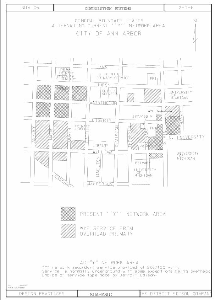
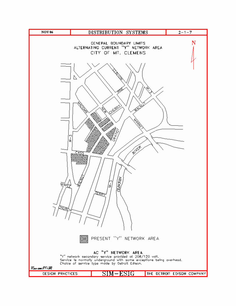
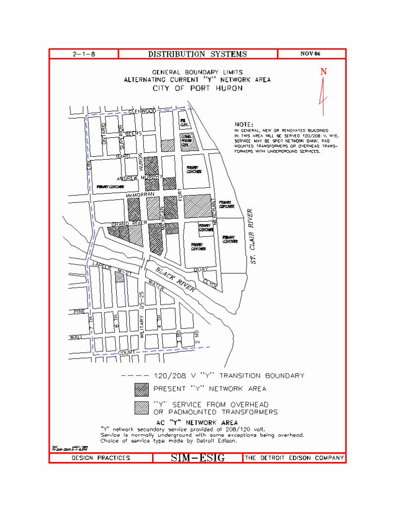
7. “Wye” Network Lighting Load Limits. Customers contemplating a lighting demand of 15 kilowatts or more in the “wye” network
areas (see maps on pages 2-1-5 to 2-1-8) should install a 4-wire service and balance the lighting load on all three phases. Consult the appropriate Company Regional Center.
KINDS OF SERVICE 1. Special Services. Specialized services are offered for street lighting and municipal pumping. Such services
are not available for general use. Consult the Company Regional Center for other special applications.
2. Character of Service. (a) Single Phase. The Company furnishes alternating current service at a nominal
frequency of 60 hertz. For lighting and small single-phase power uses, this service is suitable for 120 volt lamps and for domestic appliances nominally rated at 120 or 240 volts.
(b) Three Phase. Where available, and when the demand justifies, three-phase, four-
wire wye connected service may be had at 120/208 volts. Where this service is supplied, it is suitable for 120 volt lamps and for domestic appliances nominally rated at 120 or 208 volts. At its option, the Company may provide 120/240 volt, three-phase, four-wire delta connected service or 277/480 volt, three-phase, four-wire wye connected service for the customer’s entire requirements. Where 277/480 volt service is supplied, the customer must furnish any transformation to supply his 120/240 volt equipment.
3. Alternating Current Underground Network Service. In certain portions of the central business districts of Ann Arbor, Detroit, Mt. Clemens and
Port Huron, alternating current is usually supplied from a “wye” connected secondary network from which 120/208 volt, three-wire or 120/208 volt, three-phase, four-wire service may be taken. Consult maps on pages 2-1-5 to 2-1-8.
SIM-ESIG SIM-ESIG: 2-1


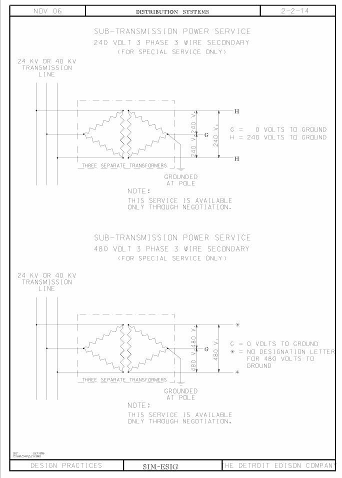

DISTRIBUTION SYSTEMS 2-3-1 NOV 06 DEFINITIONS 1. Transmission. All lines operating at 345, 230 or 120 kV, usually installed on steel towers,
steel poles or wood H-Frames. 2. Subtransmission. 120 kV lines on wood poles and all lines operating at 40 or 24 kV. 3. Distribution. All lines operating at 13.2, 8.3, and 4.8 kV or less, including system data
open wire or cable circuits. 4. Primary. All 13.2 kV, 8.3 kV (Pontiac Area) and 4.8 kV lines. 5. Secondary. Lines operating at 480 V or less, excluding system data circuits. All 480 V
secondaries require that a “DANGER 480 V” sign be installed below the rack or on the climbing side of each service buckarm.
6. Service Drop. Secondary wires going from the last pole to the building being served. For
purposes of identifying wire size, type and construction, one span of wire from a main line feeding one set of drop wires shall be considered as part of the service drop, but shall be reported and shown on facility maps as secondary.
7. Line Secondary. Pole to pole secondary wires, either open wire or multiplex, not
including service drops. 8. System Data Circuit. A Detroit Edison Company owned communication line, either open
wire or cable, used for telephone or signal purposes. 9. Cable Pole. Any pole on which overhead wires connect to underground cables. 10. Street Circuit. A series or multiple circuit that furnishes energy to street lights
exclusively. 11. Open Wire. Individually supported conductors. 12. Multiplex. The assembly of two or more insulated conductors bound to or twisted about a
bare supporting wire. These may be either primary or secondary. 13. Radial Secondary. Secondary fed by a single transformer or transformer bank and not in
parallel with or permanently connected to a second source of voltage. 14. Private Pole. A customer-owned pole. SIM-ESIG SIM-ESIG: 2-3

DISTRIBUTION SYSTEMS 2-3-2 NOV 06
15. Marking Tags. Every wood pole shall be identified with a marking tag. This tag shows
the ownership, age, height, class and species/treatment. Marking tags will be approximately 7 feet above the groundline on the face side of the pole.
16. Transformer Bank. A group of transformers physically arranged together but without
restrictions as to the electrical connections. 17. Secondary Bank. Two or more transformers or transformer banks connected in parallel
along a length of secondary usually, but not necessarily, more than 25 feet apart. There are two types of secondary banks:
(a) Solid Bank. The secondary is in a continuous run without sectionalizing fuses but
with fuses in the connections between the transformer and the line secondary. (b) Sectionalized Bank. The line secondary is sectionalized with fuses between adjacent
transformers at approximately the neutral point of the load. This configuration is sometimes referred to as a “loose bank.”
Reference: Overhead Lines Construction Standards SIM-ESIG SIM-ESIG: 2-3
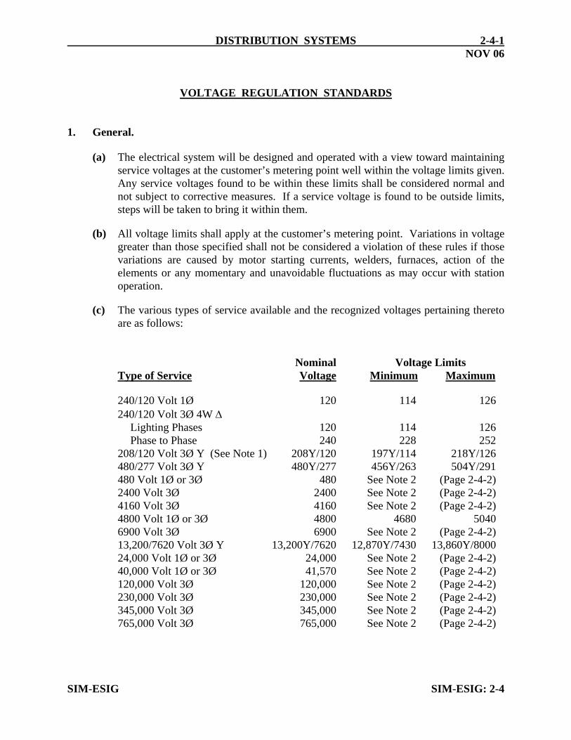
DISTRIBUTION SYSTEMS 2-4-1 NOV 06 VOLTAGE REGULATION STANDARDS 1. General. (a) The electrical system will be designed and operated with a view toward maintaining
service voltages at the customer’s metering point well within the voltage limits given. Any service voltages found to be within these limits shall be considered normal and not subject to corrective measures. If a service voltage is found to be outside limits, steps will be taken to bring it within them.
(b) All voltage limits shall apply at the customer’s metering point. Variations in voltage
greater than those specified shall not be considered a violation of these rules if those variations are caused by motor starting currents, welders, furnaces, action of the elements or any momentary and unavoidable fluctuations as may occur with station operation.
(c) The various types of service available and the recognized voltages pertaining thereto
are as follows: Nominal Voltage Limits Type of Service Voltage Minimum Maximum 240/120 Volt 1Ø 120 114 126 240/120 Volt 3Ø 4W Δ Lighting Phases 120 114 126 Phase to Phase 240 228 252 208/120 Volt 3Ø Y (See Note 1) 208Y/120 197Y/114 218Y/126 480/277 Volt 3Ø Y 480Y/277 456Y/263 504Y/291 480 Volt 1Ø or 3Ø 480 See Note 2 (Page 2-4-2) 2400 Volt 3Ø 2400 See Note 2 (Page 2-4-2) 4160 Volt 3Ø 4160 See Note 2 (Page 2-4-2) 4800 Volt 1Ø or 3Ø 4800 4680 5040 6900 Volt 3Ø 6900 See Note 2 (Page 2-4-2) 13,200/7620 Volt 3Ø Y 13,200Y/7620 12,870Y/7430 13,860Y/8000 24,000 Volt 1Ø or 3Ø 24,000 See Note 2 (Page 2-4-2) 40,000 Volt 1Ø or 3Ø 41,570 See Note 2 (Page 2-4-2) 120,000 Volt 3Ø 120,000 See Note 2 (Page 2-4-2) 230,000 Volt 3Ø 230,000 See Note 2 (Page 2-4-2) 345,000 Volt 3Ø 345,000 See Note 2 (Page 2-4-2) 765,000 Volt 3Ø 765,000 See Note 2 (Page 2-4-2) SIM-ESIG SIM-ESIG: 2-4

DISTRIBUTION SYSTEMS 2-4-2 NOV 06
2. Voltage Unbalance. Difference in phase voltages will cause unbalanced currents in three-phase motors and
raise the operating temperature. If the ratio of the lowest voltage reading to the highest is less than 0.95, corrective steps should be taken.
Notes: 1. The tabulated limits apply to suburban service. Nominal 208Y/120 volt
service for downtown network areas has limits of 200Y/116 volts minimum and 217Y/125 volts maximum.
2. The voltage spread for this type of service, which is usually unregulated, will
depend upon the requirements of the transmission system. Voltage regulators, if required, will be installed after negotiations between the customer and the Company. Voltage values within which electrical equipment should operate satisfactorily are given in the ANSI C84.1 Standard, Voltage Ratings for Electric Power Systems and Equipment (60 Hz).
SIM-ESIG SIM-ESIG: 2-4