Distribution Restriction Statement method for radon control, ... using non-perforated PVC pipe,...
39
DEPARTMENT OF THE ARMY U.S. Army Corps of Engineers CEMP-ET Washington, DC 20314-1000 ETL 1110-3-438 Technical Letter No. 1110-3-438 15 September 1993 Engineering and Design INDOOR RADON PREVENTION AND MITIGATION Distribution Restriction Statement Approved for public release; distribution is unlimited.
Transcript of Distribution Restriction Statement method for radon control, ... using non-perforated PVC pipe,...
DEPARTMENT OF THE ARMYU.S. Army Corps of Engineers
CEMP-ET Washington, DC 20314-1000 ETL 1110-3-438
Technical LetterNo. 1110-3-438 15 September 1993
Engineering and DesignINDOOR RADON PREVENTION AND MITIGATION
Distribution Restriction Statement
Approved for public release; distribution is unlimited.

Report Documentation Page
Report Date 15 Sep 1993
Report Type N/A
Dates Covered (from... to) -
Title and Subtitle Engineering and Design: Indoor Radon Prevention andMitigation
Contract Number
Grant Number
Program Element Number
Author(s) Project Number
Task Number
Work Unit Number
Performing Organization Name(s) and Address(es) Department of the Army U.S. Army Corps of EngineersWashington, DC 20314-1000
Performing Organization Report Number
Sponsoring/Monitoring Agency Name(s) and Address(es)
Sponsor/Monitor’s Acronym(s)
Sponsor/Monitor’s Report Number(s)
Distribution/Availability Statement Approved for public release, distribution unlimited
Supplementary Notes
Abstract
Subject Terms
Report Classification unclassified
Classification of this page unclassified
Classification of Abstract unclassified
Limitation of Abstract UU
Number of Pages 38

DEPARTMENT OF THE ARMY ETL 1110-3-438U.S. Army Corps of Engineers
CEMP-ET Washington, DC 20314-1000
Technical LetterNo. 1110-3-438 15 September 1993
Engineering and DesignINDOOR RADON PREVENTION AND MITIGATION
1. Purpose. This letter provides advance criteria to be usedfor prevention and mitigation in indoor radon in newlyconstructed buildings.
2. Applicability. This letter applies to HQUSACE elements,major subordinate commands, districts, laboratories, and fieldoperating activities (FOA) having military design andconstruction responsibility.
3. Action to be Taken. Pending publication of permanent mediaguidance, the criteria provided in Appendix A will be used asinterim guidance to prevent and mitigate indoor radon in allnewly constructed and substantially altered Army facilities. Thedesign requirements set forth in this letter are mandatory.
4. Implementation. This letter will have routine application asdefined in paragraph 6c, ER 1110-345-100.
FOR THE DIRECTOR OF MILITARY PROGRAMS:
1 APPENDIXAPP A - Indoor RadonPrevention and Mitigation
_________________________________________________This ETL Supersedes ETL 1110-3—427, 15 June 1990

ETL 1110-3-43815 SEP 93
APPENDIX A
US Army Corpsof Engineers
INDOOR RADON PREVENTIONAND MITIGATION

ETL 1110-3-43815 SEP 93
A-1
INDOOR RANDON PREVENTION AND MITIGATION
TABLE OF CONTENTS
1 PURPOSE . . . . . . . . . . . . . . . . . . . . . . . . . . . 1
2. SCOPE . . . . . . . . . . . . . . . . . . . . . . . . . . . . 1
3. REFERENCES . . . . . . . . . . . . . . . . . . . . . . . . . . 1
4. ROPERTIES OF RADON . . . . . . . . . . . . . . . . . . . . . . 1
5. OTHER RISKS . . . . . . . . . . . . . . . . . . . . . . . . . 1
6. PRIORITY OF FACILITY TYPES . . . . . . . . . . . . . . . . . . 2
7. INDOOR RADON CONCENTRATION AND ACTION LEVELS . . . . . . . . . 2
8. DETERMINATION OF RADON POTENT . . . . . . . . . . . . . . . . 3
9. DESIGN REQUIREMENTS . . . . . . . . . . . . . . . . . . . . . 3
10. POST CONSTRUCTION RADON MEASURE . . . . . . . . . . . . . . . 5
11. POST CONSTRUCTION RADON MITIGATION . . . . . . . . . . . . . . 6
12. DESIGN DETAILS . . . . . . . . . . . . . . . . . . . . . . . . 6
i

ETL 1110-3-43815 SEP 93
A-3
INDOOR RADON PREVENTION AND MITIGATION
1. PURPOSE: This letter establishes design criteria for all U.S.Army facilities to eliminate health risks due to indoor radon.
2. SCOPE: The design standards established herein are applicable toall newly constructed and substantially altered Army facilities bothinside and outside the Continental United States.
3. REFERENCES:a. DA Publication.
AR 200-1, Chapter 11, Army Radon Reduction Program.
b. U.S. Environmental Protection Agency (EPA) Publications.
(1) EPA 520/11-87-20, Radon Reference Manual.(2) EPA 600/8-88-087, Radon-Resistant Residential New
Construction.(3) EPA 625/5-87/019, Radon Reduction Techniques for Detached
Houses.(4) EPA 625/5-88/024, Application of Radon Reduction Methods.
(Most of the research work and publications by EPA haveconcentrated on single family, detached dwellings. Militaryfacilities are generally larger and of different constructionmethods than single family residences. The design criteria anddetails contained in this document are selectively adapted fromthe EPA data and recommendations.)
4. PROPERTIES OF RADON: Radon is a naturally occurring, chemicallyinert and water soluble radioactive gas that is undetectable by humansenses. It is formed by the radioactive decay of thorium and uranium. These source elements are found in low, but varying; concentrations insoils and rocks. Radon, being a gas, escapes from the groundfollowing paths of least resistance such as through small fissures,gravel, sand, and other porous soils. Normal subsoil investigationsdo not locate these radon paths with sufficient detail and accuracy toreliably predict points where radon emerges from the earth or probablelevels of concentration. Radon-220, derived from thorium, has a half-life of 55 seconds giving it limited time to enter buildings before itdecays to a nongaseous element. Radon-222, derived from uranium andhaving a halflife of 3.8 days, is the primary source of indoor radon. Refer to EPA 520/1-87-20, Radon Reference Manual for more detailedinformation.
5. OTHER RISKS: Health risks associated with radon are from itsdecay products, not the radon gas. Radon-222 decays in several
1

ETL 1110-3-43815 SEP 93
A-4
steps to form non-gaseous radioactive isotopes with short half-lives. Four of these successive decay products have half lives lessthan 30 minutes. These isotopes are chemically reactive and attachto building surfaces and airborne dust particles. Both attached andunattached decay products can be inhaled and attach to lung tissue.Further radioactive decay of these isotopes releases alpha particlesthat damage lung tissue and leads to lung cancer.
EPA recommends the removal of radon gas rather than removal of decayproducts with high efficiency air filters or air cleaning devices. For more information on the disadvantages of air cleaning as theprimary method for radon control, refer to EPA 625/5-87/019, RadonReduction Techniques for Detached Houses, Paragraph E.2.5. andSection 7.
6. PRIORITY OF FACILITY TYPES: Priorities for designing varioustypes of military facilities to reduce indoor radon are based upon thepriorities contained in AR 200-1, Chapter 11.
a. Priority 1: Day care centers, hospitals, schools, livingquarters including barracks, unaccompanied personnel housing(officers and enlisted) and family housing, and routinelyoccupied spaces below grade.
b. Priority 2: Offices, work areas, and other facilities having24-hour operations.
c. Priority 3: All other routinely occupied structures includingmorale, welfare and recreational facilities.
d. Priority 4: All intermittently occupied structures that areused by any military or civilian employee whose total worktime in those buildings equals or exceeds 80 hours per year.
e. Structures occupied less than 80 hours per year by anyemployee do not require radon preventive measures.
7. INDOOR RADON CONCENTRATION AND ACTION LEVELS: Radon is measuredin picocurries per liter (pCi/l) of air. EPA studies have assignedrelative health risks for various concentration levels of indoor radonbased upon periods of exposure; concentration levels below 4 pCi/l arenegligible.
The action levels given below conform to AR 200-1, Chapter 11:
a. Negligible : 0 to 4 pCi/l.
b. low : 4 to 8 pCi/l.
c. Moderate : 8 to 20 pCi/l.
d. High : 20 to 200 pci/l.
2

ETL 1110-3-43815 SEP 93
A-5
e. Very High Greater than 200 pCi/l.
8. DETERMINATION OF RADON POTENT: AR 200-1, Chapter 11 establishes aprogram for measuring indoor radon in existing buildings on Armyinstallations and buildings owned or leased by the Army (CONUS andOCONUS). The measurements were to be completed by the fourth quarterof FY 91. Each installation is required to maintain records of theradon measurements and to make annual reports on all radon mitigationactivities. The pre-mitigation measurements in existing buildingswill be the basis for potential radon levels for new facilities.
Design criteria will be based upon the highest radon measurements inexisting buildings in close proximity to the new facility. Where thenew facility is in a remote location, the highest measurements on theinstallation will determine the design criteria. In cases whereexisting radon data are not available, soil-based radon and radiummeasurement may provide useful information in evaluating radonpotentials. Procedures for using soil gas measurements to estimateradon potentials are still evolving, contact EPA for the most up-to-date guidance
9. DESIGN REQUIREMENTS:
a. New Construction. Design requirements consist of passivebarriers to seal radon entry routes and active sub-slab suctionsystems to remove radon gas from the soil under floor slabs and around below grade walls. The objective of both passive and activedesign strategies is to prevent radon entry to interior spaces.Specific design requirements, based upon facility priority andpotential radon concentration, are listed in Table 1 by letter codes. The letter codes are described below and indicated on the details inParagraph 12.
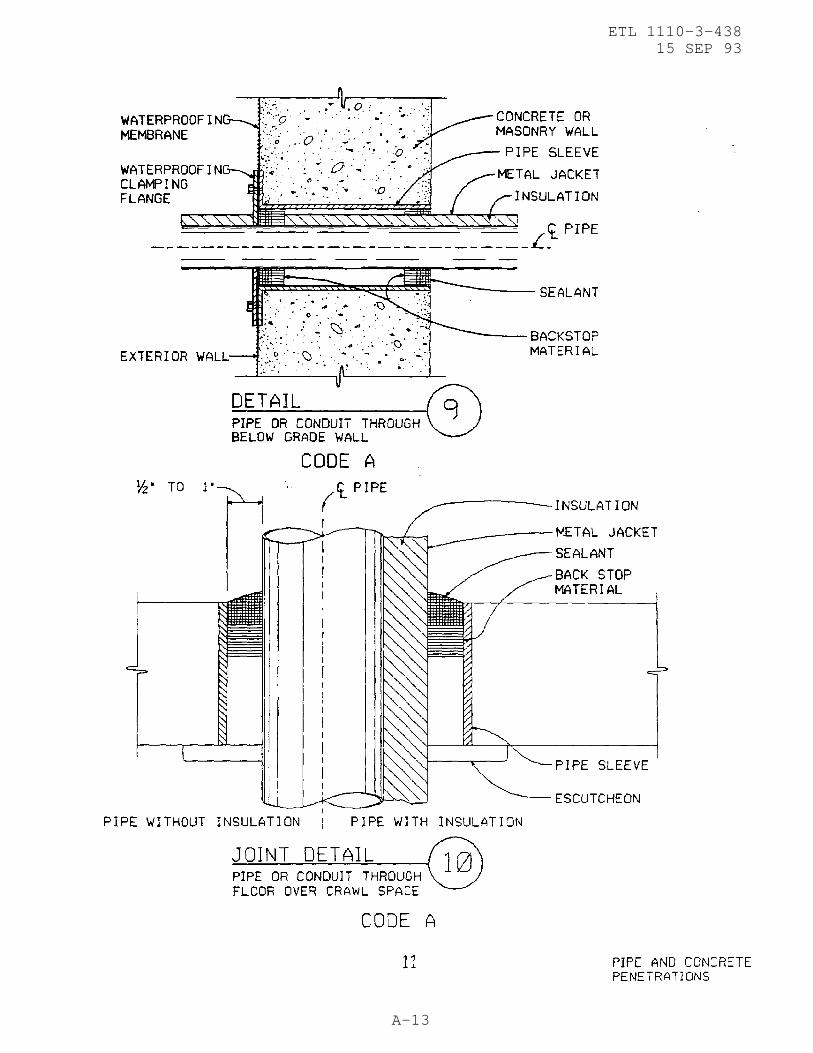
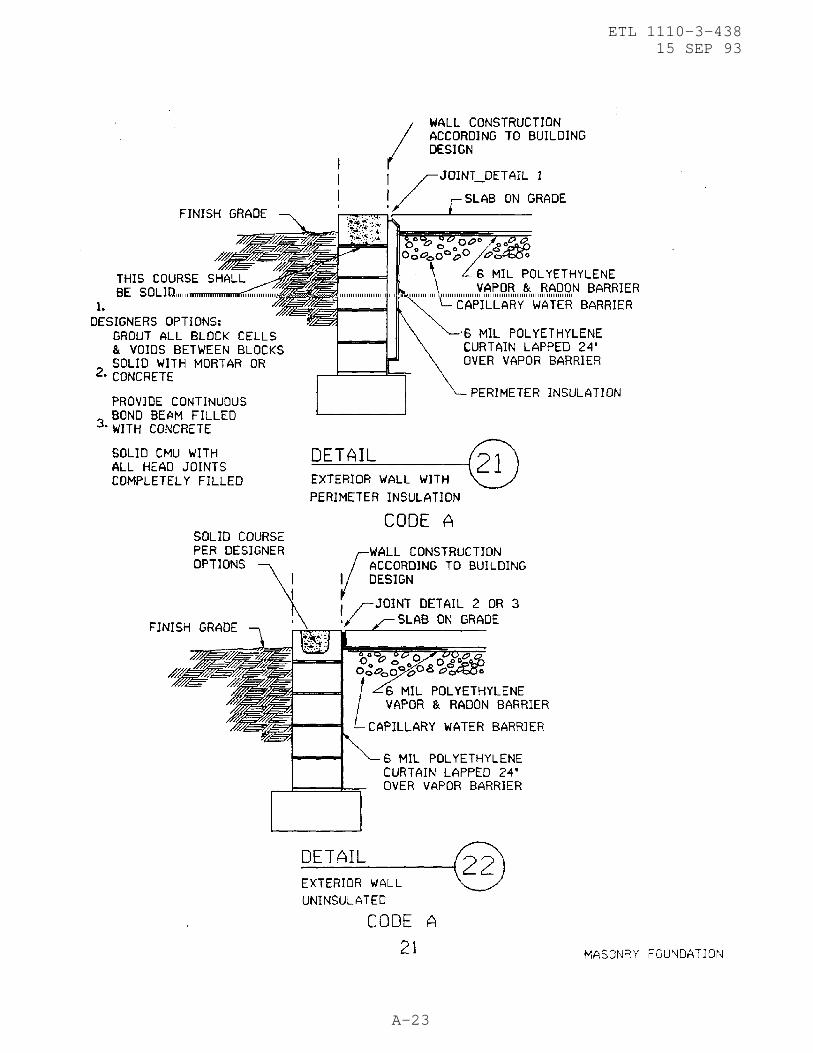
(1) Passive Barriers, Letter Code A. Passive barriers arerequired for facility priorities 1 through 4 and for all potentialradon concentration levels. Passive barriers include 6 milpolyethylene sheet in crawl spaces and under floor slabs on grade,capillary water barrier below floor slabs on grade, dampproofing orwaterproofing and protection board on below grade walls, sealants inall joints in floor slabs, below grade walls and around all pipe andconduit penetrations. Provide solid courses in hollow masonry wallsto prevent gas passage through the internal voids. Joint sealantswill be selected and installed according to TM 5-805-6 and CEGS 07920. Polyethylene sheets will be lapped 12 inches and sealed with adhesivesor pressure sensitive tape and sealed at foundation walls with mastic. Capillary water barrier will be according to CEGS 02221, dated March1991, except the last sentence in the Note under Paragraph 3.16 is notapplicable.
(2) Sub-slab Suction Systems, Letter Codes B, C, and D. Sub-slab suction systems consist of 4 inch diameter perforated PVC pipelaid in the capillary water barrier below floor slabs which are used
3

ETL 1110-3-43815 SEP 93
A-6
to create negative pressure fields under the floor. Provide a suctionstack connection, using non-perforated PVC pipe, stubbed through thefloor slab and capped. The suction stack should be near the middle ofthe under slab pipe run and be located where it can be extendedthrough the building roof with minimum changes of direction. Requirements for letter codes B, C, and D are identical except for thespacing for under slab pipe runs. In structures with basements orother below grade spaces, connect the sub-slab piping to thefoundation drainage system so that the negative pressure field isextended to the earth side of below grade walls. Where the foundationdrainage has gravity outfall, provide an interior suction stack and awater trap as shown in Details 31 and 32. Where foundation drainsdischarge to a sump, seal the sump cover and provide a suction stackconnection to the sump as shown in Detail 33; large buildings willrequire additional suction stacks remote from the sump. Buildingsites with seasonally high ground water may require a high watersensor at the suction stack connection to shut off the suction fan. Radon gas is water soluble. It is reasonable to assume that aproperly designed sub-soil drainage system will remove radon fromsites with severe ground water problems.
(3) Passive Suction Stack, Letter Code E. Extend non-perforatedPVC pipe suction stack through the roof with as few changes indirection as possible. Passive stacks are more effective in colderclimates and during winter months than during warm weather. Duringwarm weather they will be most effective in naturally ventilated, nonair conditioned buildings.
(4) Active Suction Stack, Letter Code F. Extend the suctionstack as described above for the passive stack and install an exhaustfan near the stack discharge. preferred location for the exhaust fanis above the roof. Condensation of moisture in soil gases will beminimized if the fan is located in a heated space, however, any airleakage that may occur at the fan discharge connection will blowconcentrated radon into the building. Any air leakage at the fanintake connection will reduce the suction in the stack.
(5) Design of Sub-Slab Suction System. Pipe sizing for thesuction system should be designed similar to any exhaust systemutilizing round duct. The under slab perforated pipe should be nolarger than 4 inch diameter. In very large structures, do notincrease the pipe diameter in order to increase the length of piperuns, this may reduce uniformity in the pressure field. The quantity of air flow in a sub-slab suction system is effected by anumber of variables. The most significant are porosity of the soil,permeability of the capillary water barrier, and air leakage from the building into the soil. In most locations, the air flow per 1,000 sq. ft. of slab area will be 20 cfm or less. Multiple underslab pipe runs may be cross connected below the floor using non-perforated pipe of sufficient diameter to maintain uniform pressure in all pipe runs. Multiple stacks may be connected to a commonexhaust fan. Pipes for stacks and any manifolds will be sized
4

ETL 1110-3-43815 SEP 93
A-7
according to air flow and pressure losses due to pipe length andnumber of turns.
(6) Fan Selection. The fan selected will have cfm and horsepower ratings adequate to maintain 1 inch wc static pressure at theslab penetration under constant operation. This will be mounteddirectly in or to the vertical riser with air tight connections andwill be of such design that condensation of soil gas moisture willdrain either back down the stack or onto the roof. Fans may be an in-line configuration and installed in the stack or a standard curbmounted exhaust fan.
(7) Naturally Ventilated Buildings. Naturally ventilatedbuildings that are neither heated or cooled by mechanical systems andare in any of the facility priorities 1 through 4 will be designed toinclude passive barriers (letter code A) only.
POTENTIAL RADON CONCENTRATION
PRIORITIESFOR NEGLIGIBLE LOW MODERATE HIGH VERY HIGH
FACILITY 0 TO 4 TO8 8 TO 20 TO OverTYPES 4pCi/1 pCi/l 20 pCi/l 200 pCi/l 200 pCi/l
1 A,D,E A,D,F2 A,D,E A,D,F3 A,C A,D,E4 A,B A,C
A A,B A,CA A,B A,BA A,B A,BA A A
TABLE 1. DESIGN REQUIRMENTS FOR RADON PREVENTION
b. Existing Buildings. Radon mitigation requirementsincorporated into the design of building alterations will be basedupon the facility priority and actual radon measurements in thebuilding. The design requirements in Table 1 will be evaluatedaccording to life cycle cost/benefit analysis and engineeringjudgment. For example, removal of slab-on-grade floors to install asub-slab suction system may not be cost effective when compared tothe differential in equipment and operating costs to increaseinterior air pressure or the outside-air exchange rate.
10. POST CONSTRUCTION RADON MEASURE:
a. After completion of construction, indoor radon measurementswill be made with all HVAC systems operating on normal cycles. Radon detectors and laboratory analytical services will be obtainedthrough U.S. Army Center for Pubilc Works. Ft. Belvoir. Virginia22060-5516.
b. The severity of potential. indoor radon concentration cannotbe accurately predicted. The time duration for post constructionradon measurements and the extent of mitigation work that may be
5

ETL 1110-3-43815 SEP 93
A-8
required is not quantifiable for inclusion in construction contracts. Therefore, the installation or user agency will be responsible forpost construction radon measurement and mitigation.
11. POST CONSTRUCTION RADON MITIGATION: When post construction radonmeasurements are greater than 4 pci/l, mitigation systems designedinto the facility will be activated incrementally until the radonlevel is reduced to less than 4 pci/l. The incremental steps are asfollows:
a. Activate sub-slab suction systems or power ventilate crawlspaces.
(1) Install passive vent stack(s) to sub-slab systems for lowand moderate radon levels. If subsequent radon measurementsare greater than 4 pci/ 1, then install exhaust fans foractive vent stack.
(2) Install active vent stack(s) with exhaust fans for high andvery high radon levels.
b. Increase interior positive air pressure.
c. Increase the outside-air exchange rate.
12. DESIGN DETAILS:
a. The following design details are generic in nature to depicta variety of typical conditions that are adaptable to specificbuilding designs. Some details shown may not be applicable to everybuilding; unique conditions are not included. Each detail and/orportions thereof are identified with letter codes that relate toTable 1. Additional design guidance may be found in the EPApublications listed in Paragraphs 3.a.(2), (3), and (4).
b. Reinforcing for concrete and masonry construction shall beprovided according to specific design requirements and is notindicated in the following details. Minimum reinforcement to controlshrinkage cracks in concrete slabs on grade will be 6x6-wl.4xwl.4welded wire fabric.
6

ETL 1110-3-43815 SEP 93
A-9

ETL 1110-3-43815 SEP 93
A-10

ETL 1110-3-43815 SEP 93
A-11

ETL 1110-3-43815 SEP 93
A-12
ETL 1110-3-43815 SEP 93
A-13

ETL 1110-3-43815 SEP 93
A-14

ETL 1110-3-43815 SEP 93
A-15

ETL 1110-3-43815 SEP 93
A-16

ETL 1110-3-43815 SEP 93
A-17

ETL 1110-3-43815 SEP 93
A-18

ETL 1110-3-43815 SEP 93
A-19

ETL 1110-3-43815 SEP 93
A-20

ETL 1110-3-43815 SEP 93
A-21

ETL 1110-3-43815 SEP 93
A-22
ETL 1110-3-43815 SEP 93
A-23

ETL 1110-3-43815 SEP 93
A-24

ETL 1110-3-43815 SEP 93
A-25

ETL 1110-3-43815 SEP 93
A-26

ETL 1110-3-43815 SEP 93
A-27

ETL 1110-3-43815 SEP 93
A-28

ETL 1110-3-43815 SEP 93
A-29

ETL 1110-3-43815 SEP 93
A-30

ETL 1110-3-43815 SEP 93
A-31

ETL 1110-3-43815 SEP 93
A-32

ETL 1110-3-43815 SEP 93
A-33

ETL 1110-3-43815 SEP 93
A-34

ETL 1110-3-43815 SEP 93
A-35

ETL 1110-3-43815 SEP 93
A-36