Distribution Restriction Statement · Gravity Dam on Pervious Foundation of Finite...
392
CECW-EG Engineer Manual 1110-2-1901 Department of the Army U.S. Army Corps of Engineers Washington, DC 20314-1000 EM 1110-2-1901 30 September 1986 (original) 30 April 1993 (change 1) Engineering and Design SEEPAGE ANALYSIS AND CONTROL FOR DAMS Distribution Restriction Statement Approved for public release; distribution is unlimited.
Transcript of Distribution Restriction Statement · Gravity Dam on Pervious Foundation of Finite...

CECW-EG
Engineer Manual1110-2-1901
Department of the Army
U.S. Army Corps of EngineersWashington, DC 20314-1000
EM 1110-2-1901
30 September 1986(original)
30 April 1993(change 1)
Engineering and Design
SEEPAGE ANALYSIS ANDCONTROL FOR DAMS
Distribution Restriction StatementApproved for public release;
distribution is unlimited.
CECW-EG-S
Engineer Manual
No. 111 O-2-1 901
DEPARTMENT OF THE ARMY U.S. Army Corps of Engineers Washington, DC 20314-1000
EM 1110-2-l 901
Change 1
30 April 1993
Engineering and Design SEEPAGE ANALYSIS AND CONTROL FOR DAMS
1. This change replaces Appendix D, “Filter and Drain Design and Construction” of EM 1110-2-1901, dated 30 September 1986.
2. File this change sheet in front of the publication for reference purposes.
FOR THE COMMANDER:
WILLIAM D. BROWN Colonel, Corps of Engineers
Chief of Staff

ENGINEER MANUAL EM 1110-2-190130 September 1986
ENGINEERING AND DESIGN
SEEPAGE ANALYSIS ANDCONTROL FOR DAMS
DEPARTMENT OF THE ARMYCORPS OF ENGINEERS
OFFICE OF THE CHIEF OF ENGINEERS

DAEN-ECE-G
Engineer ManualNo. 1110-2-1901
30 September 1986
Engineering and DesignSEEPAGE ANALYSIS AND CONTROL FOR DAMS
1. Purpose. This manual presents the fundamental design principles andguidance concerning seepage considerations for design of new dams and theevaluation of existing projects.
2. Applicability. This manual is applicable to all HQUSACE/OCE elements andfield operating activities having responsibility for the design andconstruction of civil works projects.
3. Discussion. All earth and rock-fill dams are subject to seepage throughthe embankment, foundation, and abutments. Concrete gravity and arch dams aresubject to seepage through the foundation and abutments. Seepage control isnecessary to prevent excessive uplift pressures, sloughing of the downstreamslope, piping through the embankment and foundation, and erosion of materialby loss into open joints in the foundation and abutments. The purpose of theproject, i.e., long-term storage, flood control, etc., may impose limitationson the allowable quantity of seepage.
FOR THE COMMANDER:
Chief of Staff
This manual supersedes EM 1110-2-1901 dated February 1952
DEPARTMENT OF THE ARMYUS Army Corps of Engineers
Washington, D. C. 20314-1000
EM-1110-2-1901
30 September 1986
DAEN-ECE-G
Engineer ManualNo. 1110-2-1901
Engineering and DesignSEEPAGE ANALYSIS AND CONTROL FOR DAMS
Table of Contents
PageParagraphSubject
CHAPTER 1. INTRODUCTION
Purpose------------------------------------
Applicability------------------------------References---------------------------------Objective and Scope------------------------General Considerations---------------------
1-11-21-31-41-5
1-11-11-11-11-1
CHAPTER 2. DETERMINATION OF PERMEABILITY OF SOILAND CHEMICAL COMPOSITION OF WATER
Darcy's Law--------------------------------
Range of Validity of Darcy's Law-----------Coefficient of Permeability----------------Factors Influencing Permeability-----------Indirect Methods for Determining
Permeability-----------------------------
Laboratory Methods for DeterminingPermeability-----------------------------
Origin, Occurrence, and Movement ofGround Water-----------------------------
Field Methods for Determiningpermeability-----------------------------
Chemical Composition of Ground Water andRiver (or Reservoir) Water---------------
2-1 2-12-2 2-42-3 2-62-4 2-9
2-5 2-20
2-6 2-28
2-7 2-30
2-8 2-33
2-9 2-34
CHAPTER 3. DETERMINATION OF PERMEABILITY OF ROCK
Permeabilities of Rock Masses--------------Flow Characteristics in Rock Masses--------Methods for Determining Rock Mass
Permeability-----------------------------
Applications of Rock Mass Permeability-----
3-1 3-13-2 3-1
3-33-4
3-33-11
This manual supersedes EM 1110-2-1901, Feb 52
i
EM 1110-2-1901
30 Sep 86
Subject Paragraph P a g e
CHAPTER 4. SEEPAGE PRINCIPLES
General Considerations----------------------Boundary Conditions-------------------------Confined and Unconfined Flow Problems-------Laplace’s Equation------------------------Methods for Solution of Laplace'sEquation------------------------------
Graphical Method for Flow NetConstruction-----------------------------
Flow Net for Anisotropic Soil---------------Flow Net for Composite Sections-------------Determination of Seepage Quantities,Escape Gradients, Seepage Forces, and
Uplift Pressures--------------------------
4-1 4-14-2 4-14-3 4-24-4 4-3
4-5
4-64-74-8
4-5
4-94-144-14
4-9 4-21
CHAPTER 5. CONFINED FLOW PROBLEMS
General Considerations----------------------Gravity Dam on Pervious Foundation of
Finite Depth------------------------------Gravity Dams on Infinitely DeepPervious Foundations------------------------
5-1 5-1
5-2 5-1
5-3 5-1
CHAPTER 6. UNCONFINED FLOW PROBLEMS
Introduction --------------------------------
Homogeneous Earth Dam on ImperviousFoundation --------------------------------
Earth Dam with Horizontal Drain onImpervious Foundation---------------------
Earth Dam with Toe Drain on ImperviousFoundation --------------------------------
Earth Dam with Vertical or near VerticalHorizontal Drains on ImperviousFoundation--------------------------------
Flow Net for a Composite Zoned Dam----------Zoned Earth Dam on Pervious Foundation------
6-1 6-1
6-2 6-1
6-3 6-10
6-4 6-10
6-5 6-106-6 6-106-7 6-17
CHAPTER 7. SEEPAGE TOWARD WELLS
Use of Wells--------------------------------Analysis of Well Problems-------------------Basic Well Equations for Steady State
Flow--------------------------------------Special Conditions--------------------------Nonsteady State Flow------------------------
7-1 7-17-2 7-1
7-3 7-27-4 7-117-5 7-21
ii

EM 1110-2-190130 Sep 86
Subject Paragraph P a g e
CHAPTER 8. SEEPAGE CONTROL IN EMBANKMENTS
CHAPTER 9. SEEPAGE CONTROL IN EARTH FOUNDATIONS
CHAPTER 10.
CHAPTER 11.
CHAPTER 12. REMEDIAL SEEPAGE CONTROL
General-------------------------------------Methods for Seepage Control-----------------Flat Slopes Without Drains------------------Zoning Embankments--------------------------Vertical (or Inclined) and Horizontal
Drains------------------------------------
Seepage Control Against Earthquake
8-18-28-38-4
8-5
8-6
8-18-18-18-1
Effects-----------------------------------
8-8
8-18
General-------------------------------------Selection of Method for Seepage
9-1
9-29-39-49-59-69-79-89-9
9-1
Control-----------------------------------Horizontal Drains---------------------------Cutoffs-------------------------------------Upstream Impervious Blanket-----------------Downstream Seepage Berms--------------------Relief Wells--------------------------------Trench Drain--------------------------------Concrete Galleries--------------------------
9-19-19-19-489-589-629-839-84
SEEPAGE CONTROL THROUGH EARTH ABUTMENTSADJACENT TO STRUCTURES AND BENEATHSPILLWAYS AND STILLING BASINS
Through Earth Abutments---------------------Adjacent to Outlet Conduits-----------------Beneath Spillways and Stilling Basins-------
10-110-210-3
10-110-110-3
SEEPAGE CONTROL IN ROCK FOUNDATIONS ANDABUTMENTS
General Considerations----------------------Cutoff Trenches-----------------------------Abutment Impervious Blankets----------------Drainage and Grouting Galleries and
Tunnels-----------------------------------Grouting of Foundations and Abutments-------Surface Treatment of Foundations andAbutments---------------------------------
11-111-211-3
11-111-111-2
11-411-5
11-211-3
11-6 11-3
General Considerations---------------------- 12-1 12-1Remedial Methods---------------------------- 12-2 12-1Storage Restriction------------------------- 12-3 12-2Grouting ------------------------------------ 12-4 12-2
iii
EM 1110-2-1901
30 Sep 86
Subject
CHAPTER 13.
CHAPTER 14.
APPENDIX A.
APPENDIX B.
APPENDIX C.
Upstream Impervious Blanket----------------- 12-5Downstream Berm----------------------------- 12-6Slurry Trench Cutoff------------------------ 12-7Relief Wells-------------------------------- 12-8Drainage of Downstream Slope---------------- 12-9
P a g e
12-412-612-612-1112-12
MONITORING PERFORMANCE OF SEEPAGE CONTROLMEASURES
General Considerations---------------------- 13-1 13-1Piezometers for Seepage Pressures----------- 13-2 13-1Flow Measurements--------------------------- 13-3 13-12Seepage Water Analysis---------------------- 13-4 13-18Remote Sensing Methods---------------------- 13-5 13-20
INSPECTION, MAINTENANCE, AND REHABILITA-TION OF SEEPAGE CONTROL MEASURES
Introduction -------------------------------- 14-1 14-1Inspection---------------------------------- 14-2 14-1Maintenance--------------------------------- 14-3 14-1Rehabilitation------------------------------ 14-4 14-3
REFERENCESGovernment Publications---------------------Non-Government Publications-----------------
APPROXIMATE METHODS FOR ANALYSIS OF FLOWPROBLEMS
A-1A-11
Introduction--------------------------------Electrical Analogy--------------------------Sand Tank Model-----------------------------Viscous Flow Models-------------------------Method of Fragments-------------------------Finite Difference Method--------------------Finite Element Method-----------------------
B-1 B-1B-2 B-1B-3 B-2B-4 B-5B-5 B-5B-6 B-28B-7 B-29
ANALYSIS OF PRESSURE INJECTION TESTS(Ziegler 1976)
Water pressure Tests------------------------Air pressure Tests--------------------------pressure Holding Testy----------------------
C-1C-2C-3
C-1C-11C-17
Paragraph
iv

EM 1110-2-190130 Sep 86
Subject Paragraph P a g e
APPENDIX D. FILTER AND DRAIN DESIGN AND CONSTRUCTION
General---------------------------------------Stability-------------------------------------Permeability----------------------------------Applicability---------------------------------Perforated Pipe---------------------------Gap-Graded Base---------------------------Gap-Graded Filter-------------------------Broadly-Graded Base-----------------------Graded Filter Design----------------------Geotextiles-----------------------------------Construction----------------------------------Monitoring------------------------------------
D-1D-2D-3D-4D-5D-6D-7D-8D-9D-10D-11D-12
D-1D-1D-2D-2D-3D-3D-5D-5D-5D-6D-6D-8
v
EM 1110-2-190130 Sep 86
CHAPTER 1INTRODUCTION
1-1. Purpose. This manual provides guidance and information concerning seep-age analysis and control for dams.
1-2. Applicability. The provisions of this manual are applicable to allHQUSACE/OCE elements and field operating activities (FOA) having responsibil-ity for seepage analysis and control for dams.
1-3 References. Appendix A contains a list of Government and non-Governmentreferences pertaining to this manual. Each reference is identified in thetext by either the designated publication number or by author and date.Reference to cited material in tables and figures is identified throughout themanual by superscripted numbers (item 1, 2, etc.) that correspond to similarlynumbered items in Appendix A.
1-4. Objective and Scope. The objective of this manual is to provide a guidefor seepage analysis and control for dams.
1-5. General Considerations. All earth and rock-fill dams are subject toseepage through the embankment, foundation, and abutments. Concrete gravityand arch dams are subject to seepage through the foundation and abutments.Seepage control is necessary to prevent excessive uplift pressures, sloughingof the downstream slope, piping through the embankment and foundation, anderosion of material by loss into open joints in the foundation and abutments.The purpose of the project, i.e., long-term storage, flood control, etc., mayimpose limitations on the allowable quantity of seepage (Sowers 1977).
1-1
EM 1110-2-190130 Sep 86
CHAPTER 2DETERMINATION OF PERMEABILITY OF SOIL AND
CHEMICAL COMPOSITION OF WATER
2-1. Darcy's Law.
a. Development of Darcy's Law. Henry Darcy, a French engineer, con-ducted a laboratory experiment to study the flow of water in verticals andfilters which he published in his 1856 treatise. The results of his experimentindicated that (Rouse and Ince 1957)
v = ki (2-1)
or since Q = VA
or using q =
Q = kiAt
q = kiA
(2-2)
(2-3)
\where
v = discharge velocity
k = (1)Darcy's coefficient of permeability
i = hydraulic gradient (head loss/length over which head loss occurs)
Q = quantity of discharge
A = cross-sectional area of flow
t = time of flow
q = rate of discharge
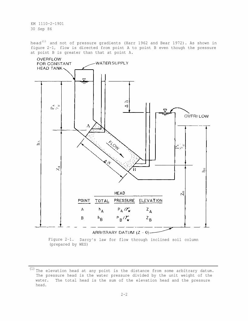
b. Extension to Inclined Soil Column. Darcy's law may be extended toflow through an inclined soil column given in figure 2-1 (Harr 1962). Asindicated in equation 2-1, flow is a consequence of differences in total
(1) Commonly called the coefficient of permeability or the permeability.
2-1
EM 1110-2-190130 Sep 86
head(l) and not of pressure gradients (Harr 1962 and Bear 1972). As shown infigure 2-1, flow is directed from point A to point B even though the pressureat point B is greater than that at point A.
Figure 2-1. Darcy's law for flow through inclined soil column(prepared by WES)
(1) The elevation head at any point is the distance from some arbitrary datum.The pressure head is the water pressure divided by the unit weight of thewater. The total head is the sum of the elevation head and the pressurehead.
2-2
EM 1110-2-1901
30 Sep 86
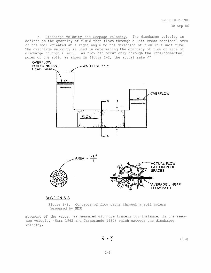
c. Discharge Velocity and Seepage Velocity. The discharge velocity isdefined as the quantity of fluid that flows through a unit cross-sectional areaof the soil oriented at a right angle to the direction of flow in a unit time.The discharge velocity is used in determining the quantity of flow or rate ofdischarge through a soil. As flow can occur only through the interconnectedpores of the soil, as shown in figure 2-2, the actual rate of
Figure 2-2. Concepts of flow paths through a soil column(prepared by WES)
movement of the water, as measured with dye tracers for instance, is the seep-age velocity (Harr 1962 and Casagrande 1937) which exceeds the dischargevelocity.
2-3
(2-4)
EM 1110-2-1901
30 Sep 86
where
seepage velocity
n = porosity (ratio of volume of voids to the total volume of the soilmass)
It follows that
Equation 2-5 is a useful expression in estimating field permeabilities usingdye tracers (Soil Conservation Service 1978).
2-2. Range of Validity of Darcy's Law.
a. Lower Bound. Darcy's law (equations 2-1 through 2-3) applies tolinear flow (adjacent flow lines are locally straight and parallel). For flowsthrough soils, there are two situations where the validity of this linearrelationship may not hold. For highly plastic clays of low permeability, theremay be a threshold hydraulic gradient below which flow does not take place.Such conditions may occur in deeply buried clays and clay shales. For manypractical seepage problems the rate of flow through these soil layers is sosmall that they can be considered to be impervious (Mitchell 1976, Chugaev1971, Basak and Madhav 1979, and Muskat 1946).
b. Upper Bound. Of greater practical importance is the upper limit onthe range of validity of Darcy's law. It has been recognized that, at veryhigh flow rates, Darcy's law does not hold (Chugaev 1971). The upper limit isusually identified using Reynolds number, a dimensionless number that expressesthe ratio of internal to viscous forces during flow. It is often used in fluidmechanics to distinguish between laminar flow (fluid layer flows alongside ofanother at approximately the same velocity with no macroscopic mixing of fluidparticles) at low velocities and turbulent flow (velocity fluctuations, bothparallel and transverse, are imposed upon the mean motion with mixing of thefluid particles) at high velocities. The Reynolds number for flow throughsoils is
(2-6)
where
Reynolds number
D = average diameter of soil particles
2-4
EM 1110-2-190130 Sep 86
= density of fluid
= coefficient of dynamic viscosity of fluid
The critical value-of Reynolds number at which the flow in soils changes fromlaminar to turbulent has been determined experimentally by various investiga-tors to range from 1 to 12 (Harr 1962 and Chugaev 1971). Assuming a water
temperature of 20º C, substituting = 998.2 kg/m3 and µ = 1.002 x 10⁻³
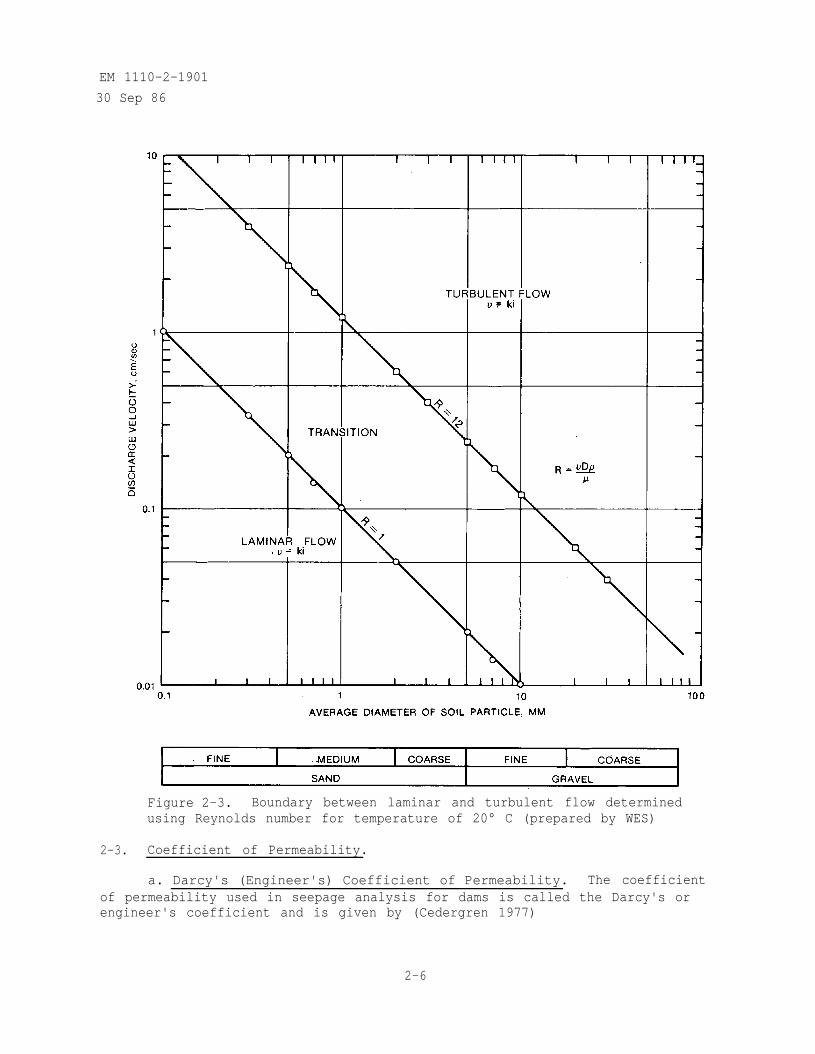
kg/msec into equation 2-6, and assuming values of D and solving for v with= 1 and = 12 gives the relationship shown in figure 2-3 which definesthe upper bound of the validity of Darcy's law. Depending on the dischargevelocity, Darcy's law is generally applicable for silts through medium sands.
c. Turbulent Flow.
(1) Estimating Permeability from Empirical Equation. For flow throughsoils more pervious than medium sands, flow is likely to be turbulent. Underturbulent conditions, the seepage velocity in a material with monosized soilparticles (coarse sands and/or gravels) can be estimated from the followingequation (Wilkins 1956, Leps 1973, and Stephenson 1979).
(2-7)
where
= seepage velocity in inches per second
w = an empirical constant, which depends on the shape and roughness ofthe soil particles and viscosity of water and varies from 33 for
crushed gravel to 46 for polished marbles, in inch 1/2 per second
M = hydraulic mean radius of the rock voids (for a given volume ofparticles equal to the volume of voids divided by the total surfacearea of the particles, or the void ratio divided by the surface areaper unit volume of solids) in inches
i = hydraulic gradient
The coefficient of permeability is obtained from the seepage velocity usingequation 2-5. For well-graded soils, the D50 size (50 percent finer by weight)can be used to calculate the hydraulic mean radius provided that the minus1-in.-size material is less than 30 percent by weight. If there is more than30 percent of minus 1-in .-size material, the permeability should be determinedexperimentally (Leps 1973).
(2) Determining Permeability Experimentally. Alternatively, for flowthrough soils more pervious than medium sands, the relationship betweenhydraulic gradient and discharge velocity can be determined experimentally(Cedergren 1977).
2-5
EM 1110-2-1901
30 Sep 86
Figure 2-3. Boundary between laminar and turbulent flow determinedusing Reynolds number for temperature of 20° C (prepared by WES)
2-3. Coefficient of Permeability.
a. Darcy's (Engineer's) Coefficient of Permeability. The coefficientof permeability used in seepage analysis for dams is called the Darcy's orengineer's coefficient and is given by (Cedergren 1977)
2-6
EM 1110-2-1901
30 Sep 86
(2-8)
or since Q = VA
or using q =
(2-9)
(2-10)
The coefficient of permeability is defined as the rate of discharge-of waterat a temperature of 20º C under conditions of laminar flow through a unitcross-sectional area of a saturated soil medium. The coefficient of perme-ability has the dimensions of a velocity and is usually expressed in centi-meters per second. Permeability computed on the basis of Darcy's law islimited to the conditions of laminar flow and complete saturation of the soil.Under conditions of partial saturation, the flow is in a transient state andis time dependent. To analyze natural flow conditions which depart from theDarcy flow condition, it is sometimes necessary to apply Darcy's law in condi-tions where it is not strictly valid. When this is done, the effects of tur-bulent flow and partial saturation on the permeability must be recognized andtaken into consideration (Cedergren 1975).
b. Intrinsic (Specific) Permeability. The coefficient of permeabilityof a soil material varies for different pore fluids depending upon theirdensity and viscosity as follows:
where
= intrinsic permeability
= unit weight of pore fluid
µ = viscosity of pore fluid
(2-11)
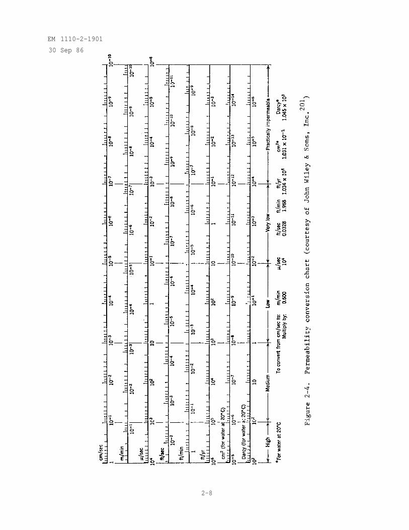
The intrinsic permeability has the dimensions of length squared and isexpressed in square centimeters or Darcy's (equal to 1.01 x 10⁻⁸ cm2). Fig-ure 2-4 is a chart for the conversion of permeability values from one set of
2-7
EM 1110-2-1901
30 Sep 86
2-8
EM 1110-2-1901
30 Sep 86
units to another (Lohman et al. 1972). Substituting equation 2-11 intoequation 2-1
(2-12)
Equation 2-12 may be used when dealing with more than one fluid or with temper-ature variations. This is widely used in the petroleum industry where thepresence of gas, oil, and water occur in multiphase flow systems (Freeze andCherry 1979, and Bureau of Reclamation 1977). In seepage analysis for earthdams where we are primarily interested in the flow of water subject to smallchanges in temperature, this refinement is seldom required.
c. Transmissivity Factor. In order to describe the flow characteris-tics of an aquifer (saturated permeable geologic unit that can transmitsignificant quantities of water under ordinary hydraulic gradients),C. V. Thesis introduced the term transmissivity which is defined as (Bureau ofReclamation 1977)
T = kt (2-13)
where
T = transmissivity factor
k = average permeability
t = aquifer thickness
Transmissivity represents the rate of discharge for a gradient of unitythrough a vertical strip of aquifer one unit wide and has dimensions of lengthsquared per unit time and is usually expressed in square feet per day.
2-4. Factors Influencing Permeability.
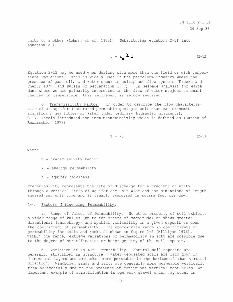
a. Range of Values of Permeability. No other property of soil exhibitsa wider range of values (up to ten orders of magnitude) or shows greaterdirectional (anisotropy) and spatial variability in a given deposit as doesthe coefficient of permeability. The approximate range in coefficients ofpermeability for soils and rocks is shown in figure 2-5 (Milligan 1976).Within the range, extreme variations of permeability in situ are possible dueto the degree of stratification or heterogeneity of the soil deposit.
b. Variation of In Situ Permeability. Natural soil deposits aregenerally stratified in structure. Water-deposited soils are laid down in'horizontal layers and are often more permeable in the horizontal than verticaldirection. Windblown sands and silts are generally more permeable verticallythan horizontally due to the presence of continuous vertical root holes. Animportant example of stratification is openwork gravel which may occur in
2-9
EM 1110-2-1901
30 Sep 86
Figure 2-5. Approximate range in coefficient of
permeability of soils and rocks (from Milligan224
)
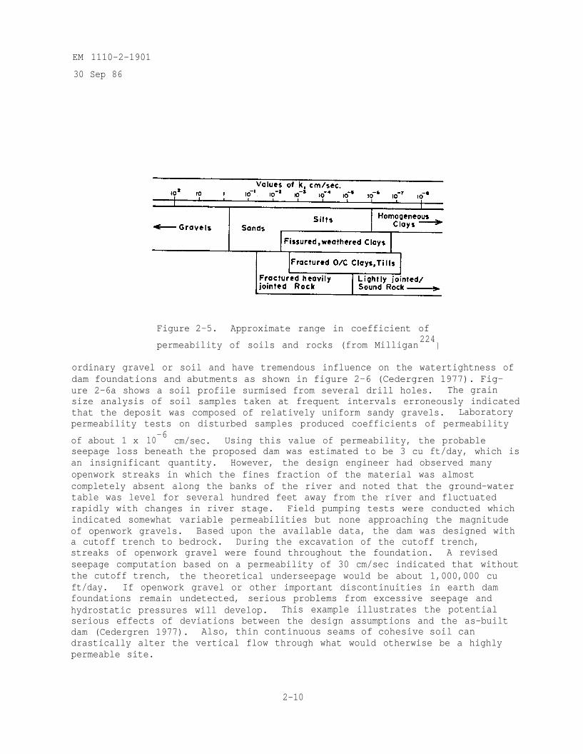
ordinary gravel or soil and have tremendous influence on the watertightness ofdam foundations and abutments as shown in figure 2-6 (Cedergren 1977). Fig-ure 2-6a shows a soil profile surmised from several drill holes. The grainsize analysis of soil samples taken at frequent intervals erroneously indicatedthat the deposit was composed of relatively uniform sandy gravels. Laboratorypermeability tests on disturbed samples produced coefficients of permeability
of about 1 x 10⁻⁶
cm/sec. Using this value of permeability, the probableseepage loss beneath the proposed dam was estimated to be 3 cu ft/day, which isan insignificant quantity. However, the design engineer had observed manyopenwork streaks in which the fines fraction of the material was almostcompletely absent along the banks of the river and noted that the ground-watertable was level for several hundred feet away from the river and fluctuatedrapidly with changes in river stage. Field pumping tests were conducted whichindicated somewhat variable permeabilities but none approaching the magnitudeof openwork gravels. Based upon the available data, the dam was designed witha cutoff trench to bedrock. During the excavation of the cutoff trench,streaks of openwork gravel were found throughout the foundation. A revisedseepage computation based on a permeability of 30 cm/sec indicated that withoutthe cutoff trench, the theoretical underseepage would be about 1,000,000 cuft/day. If openwork gravel or other important discontinuities in earth damfoundations remain undetected, serious problems from excessive seepage andhydrostatic pressures will develop. This example illustrates the potentialserious effects of deviations between the design assumptions and the as-builtdam (Cedergren 1977). Also, thin continuous seams of cohesive soil candrastically alter the vertical flow through what would otherwise be a highlypermeable site.
2-10
EM 1110-2-1901
30 Sep 86
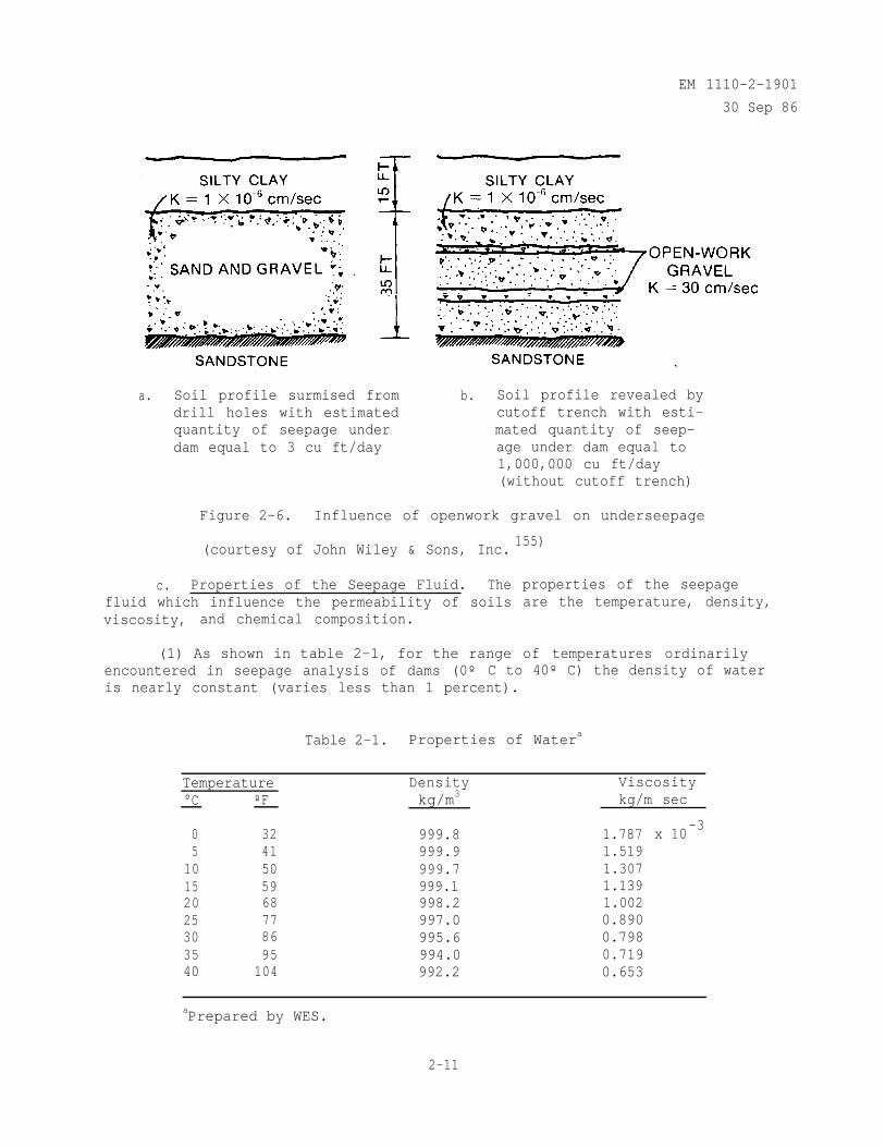
a. Soil profile surmised fromdrill holes with estimatedquantity of seepage underdam equal to 3 cu ft/day
b. Soil profile revealed bycutoff trench with esti-mated quantity of seep-age under dam equal to1,000,000 cu ft/day(without cutoff trench)
Figure 2-6. Influence of openwork gravel on underseepage
(courtesy of John Wiley & Sons, Inc.155)
c. Properties of the Seepage Fluid. Thefluid which influence the permeability of soilsviscosity, and chemical composition.
(1) As shown in table 2-1, for the range
properties of the seepageare the temperature, density,
of temperatures ordinarilyencountered in seepage analysis of dams (0º C to 40º C) the density of wateris nearly constant (varies less than 1 percent).
Table 2-1. Properties of Watera
Temperature°C ºF
Density Viscositykg/m3 kg/m sec
0 32 999.8 1.7875 41 999.9 1.519
10 50 999.7 1.30715 59 999.1 1.13920 68 998.2 1.00225 77 997.0 0.89030 86 995.6 0.79835 95 994.0 0.71940 104 992.2 0.653
x 10-3
aPrepared by WES.
2-11
EM 1110-2-1901
30 Sep 86
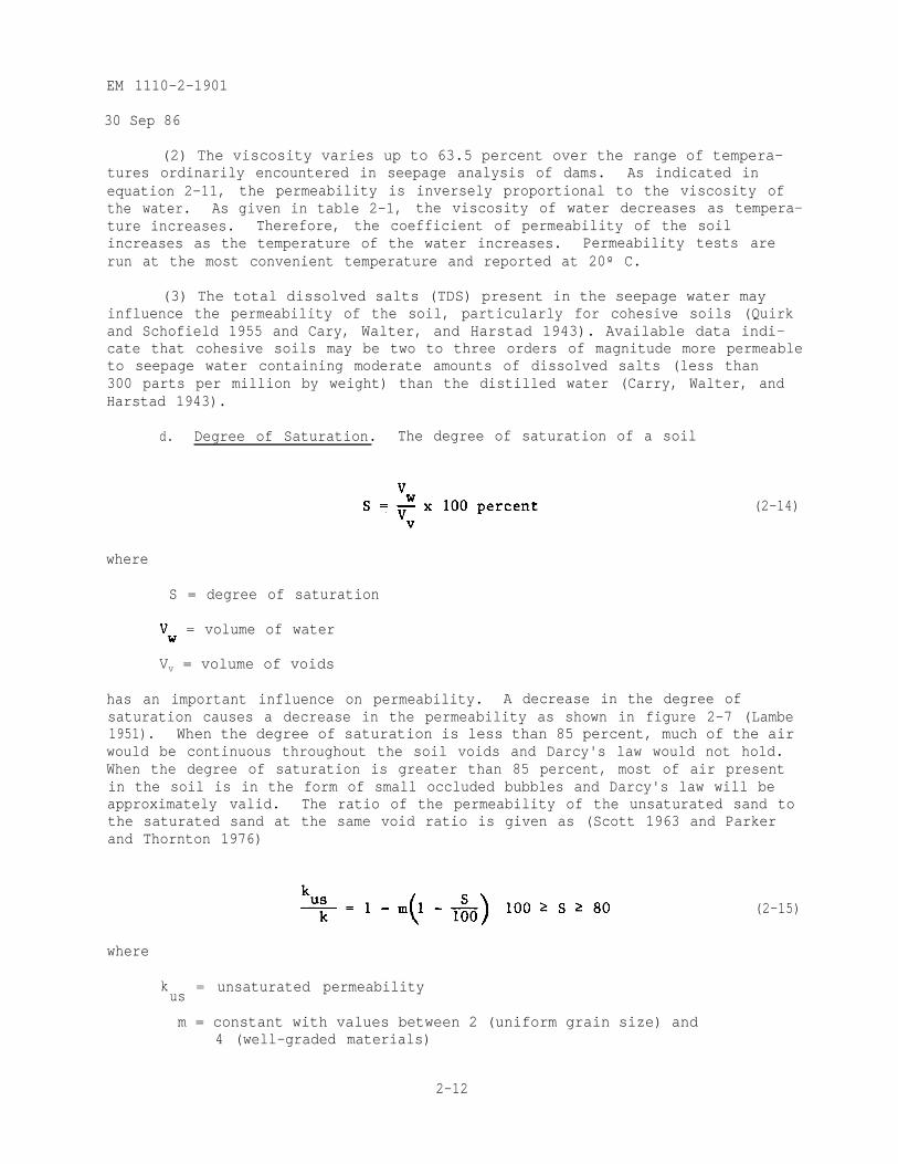
(2) The viscosity varies up to 63.5 percent over the range of tempera-tures ordinarily encountered in seepage analysis of dams. As indicated inequation 2-11, the permeability is inversely proportional to the viscosity ofthe water. As given in table 2-1, the viscosity of water decreases as tempera-ture increases. Therefore, the coefficient of permeability of the soilincreases as the temperature of the water increases. Permeability tests arerun at the most convenient temperature and reported at 20º C.
(3) The total dissolved salts (TDS) present in the seepage water mayinfluence the permeability of the soil, particularly for cohesive soils (Quirkand Schofield 1955 and Cary, Walter, and Harstad 1943). Available data indi-cate that cohesive soils may be two to three orders of magnitude more permeableto seepage water containing moderate amounts of dissolved salts (less than300 parts per million by weight) than the distilled water (Carry, Walter, andHarstad 1943).
d. Degree of Saturation. The degree of saturation of a soil
where
S = degree of saturation
(2-14)
= volume of water
Vv = volume of voids
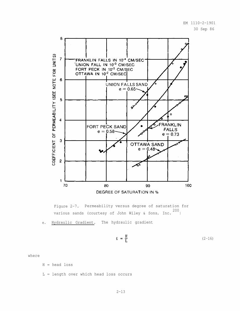
has an important influence on permeability. A decrease in the degree ofsaturation causes a decrease in the permeability as shown in figure 2-7 (Lambe1951). When the degree of saturation is less than 85 percent, much of the airwould be continuous throughout the soil voids and Darcy's law would not hold.When the degree of saturation is greater than 85 percent, most of air presentin the soil is in the form of small occluded bubbles and Darcy's law will beapproximately valid. The ratio of the permeability of the unsaturated sand tothe saturated sand at the same void ratio is given as (Scott 1963 and Parkerand Thornton 1976)
where
kus
= unsaturated permeability
m = constant with values between 2 (uniform grain size) and4 (well-graded materials)
(2-15)
2-12
EM 1110-2-1901
30 Sep 86
Figure 2-7. Permeability versus degree of saturation for
various sands (courtesy of John Wiley & Sons, Inc.200
)
e. Hydraulic Gradient. The hydraulic gradient
(2-16)
where
H = head loss
L = length over which head loss occurs
2-13
EM 1110-2-1901
30 Sep 86
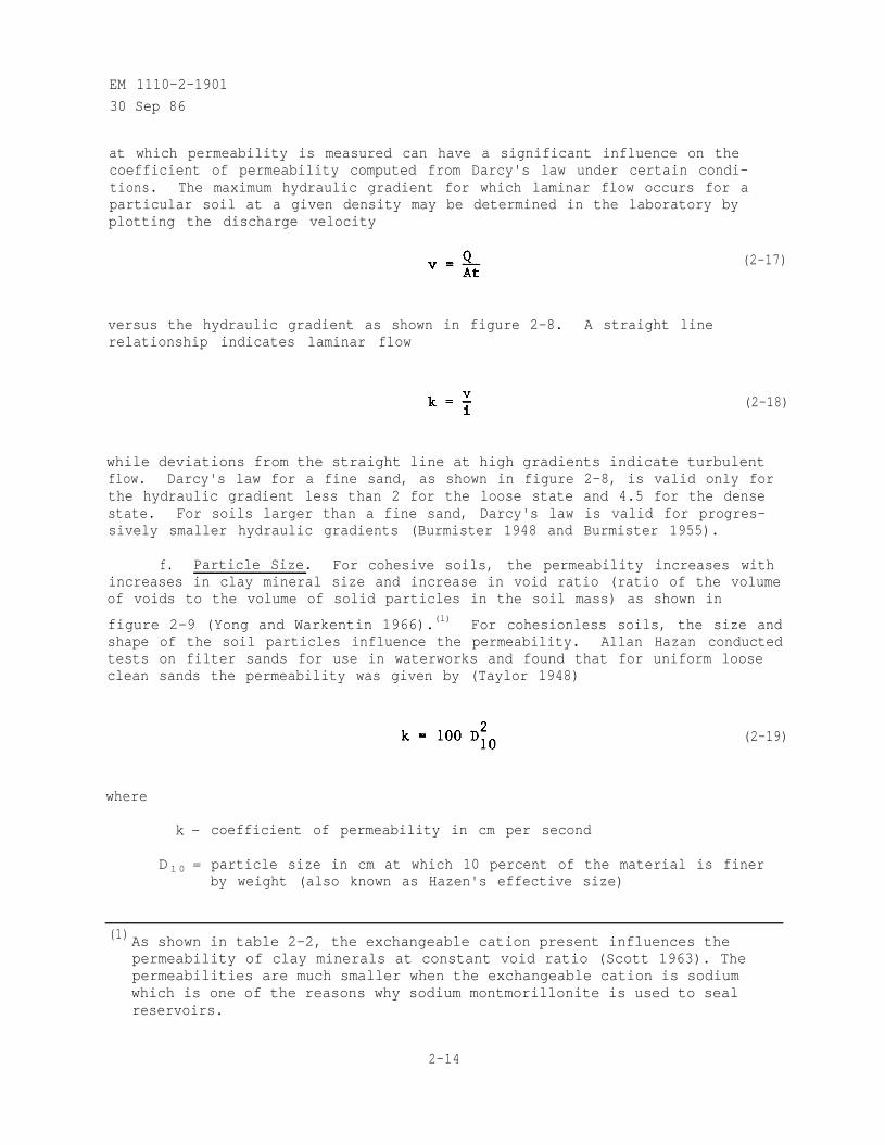
at which permeability is measured can have a significant influence on thecoefficient of permeability computed from Darcy's law under certain condi-tions. The maximum hydraulic gradient for which laminar flow occurs for aparticular soil at a given density may be determined in the laboratory byplotting the discharge velocity
(2-17)
versus the hydraulic gradient as shown in figure 2-8. A straight linerelationship indicates laminar flow
(2-18)
while deviations from the straight line at high gradients indicate turbulentflow. Darcy's law for a fine sand, as shown in figure 2-8, is valid only forthe hydraulic gradient less than 2 for the loose state and 4.5 for the densestate. For soils larger than a fine sand, Darcy's law is valid for progres-sively smaller hydraulic gradients (Burmister 1948 and Burmister 1955).
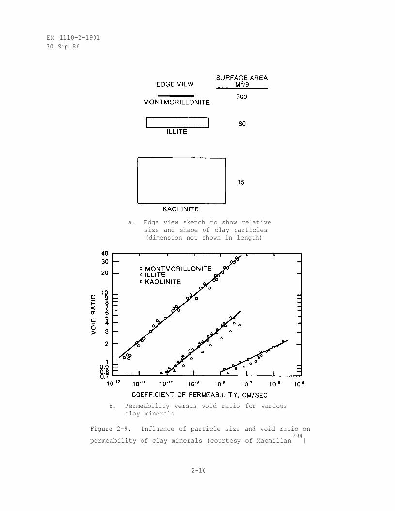
f. Particle Size. For cohesive soils, the permeability increases withincreases in clay mineral size and increase in void ratio (ratio of the volumeof voids to the volume of solid particles in the soil mass) as shown in
figure 2-9 (Yong and Warkentin 1966).(l) For cohesionless soils, the size andshape of the soil particles influence the permeability. Allan Hazan conductedtests on filter sands for use in waterworks and found that for uniform looseclean sands the permeability was given by (Taylor 1948)
(2-19)
where
k - coefficient of permeability in cm per second
D 1 0 = particle size in cm at which 10 percent of the material is finerby weight (also known as Hazen's effective size)
(1) As shown in table 2-2, the exchangeable cation present influences thepermeability of clay minerals at constant void ratio (Scott 1963). Thepermeabilities are much smaller when the exchangeable cation is sodiumwhich is one of the reasons why sodium montmorillonite is used to sealreservoirs.
2-14
EM 1110-2-1901
30 Sep 86
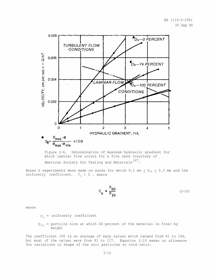
Figure 2-8. Determination of maximum hydraulic gradient forwhich laminar flow occurs for a fine sand (courtesy of
American Society for Testing and Materials147
)
Hazen's experiments were made on sands for which 0.1 mm < D10 < 0.3 mm and theuniformity coefficient, Cu < 5 , where
where
Cu = uniformity coefficient
D 6 0 = particle size at which 60 percent of the material is finer byweight
(2-20)
The coefficient 100 is an average of many values which ranged from 41 to 146,but most of the values were from 81 to 117. Equation 2-19 makes no allowancefor variations in shape of the soil particles or void ratio.
2-15
EM 1110-2-190130 Sep 86
a. Edge view sketch to show relativesize and shape of clay particles(dimension not shown in length)
b. Permeability versus void ratio for variousclay minerals
Figure 2-9. Influence of particle size and void ratio on
permeability of clay minerals (courtesy of Macmillan294
)
2-16
EM 1110-2-1901
30 Sep 86
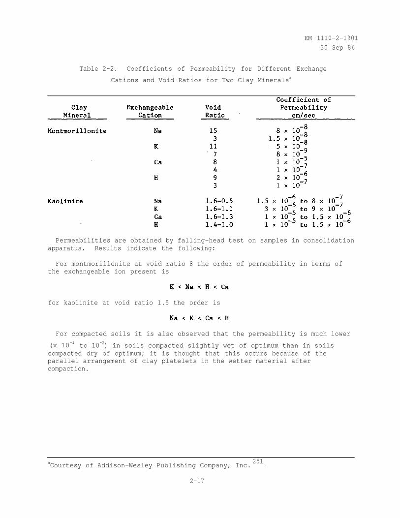
Table 2-2. Coefficients of Permeability for Different Exchange
Cations and Void Ratios for Two Clay Mineralsa
Permeabilities are obtained by falling-head test on samples in consolidationapparatus. Results indicate the following:
For montmorillonite at void ratio 8 the order of permeability in terms ofthe exchangeable ion present is
for kaolinite at void ratio 1.5 the order is
For compacted soils it is also observed that the permeability is much lower
(x 10-l to 10-2) in soils compacted slightly wet of optimum than in soilscompacted dry of optimum; it is thought that this occurs because of theparallel arrangement of clay platelets in the wetter material aftercompaction.
aCourtesy of Addison-Wesley Publishing Company, Inc.251
.
2-17
EM 1110-2-1901
30 Sep 86
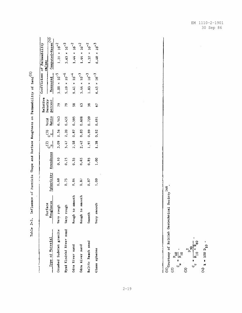
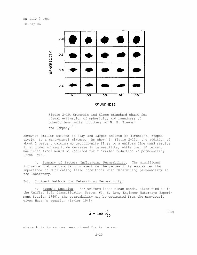
g. Particle Shape and Surface Roughness. Cohesionless soil particleshave different particle shapes and surface roughness dependent on the distancethey have been transported by flowing water from the place of original ero-sion. As shown in table 2-3, the measured permeability is several orders ofmagnitude lower for angular sand particles with rough surfaces than forrounded sand particles with smooth surfaces (Burmister 1948). For uniformcohesionless soils, crushing of particles during compaction with resultingdecrease in permeability occurs to a higher degree in soils with angularshapes and rough surfaces than in soils with rounded shapes and smooth sur-faces. Crushing of particles during compaction leads to an increase in theamount of silt-sized particles (smaller than No. 200 sieve or 0.074 mm) whichresults in lower permeability. For this and other reasons (cementation inlimestones and arching due to particle angularity) crushed rock is generallynot used for filters in earth dams. Also, table 2-3 compares the measuredpermeability with the permeability computed from equation 2-19 developed byHazen for uniform loose clean sands. The agreement between measured andcomputed permeability is within one order of magnitude for uniform sands andglass spheres. Therefore, Hazen's equation should be used only for uniformsands (sphericity and roundness > 0.90). The sphericity and roundness may beestimated for sands using figure 2-10 (Krumbein and Sloss 1951).
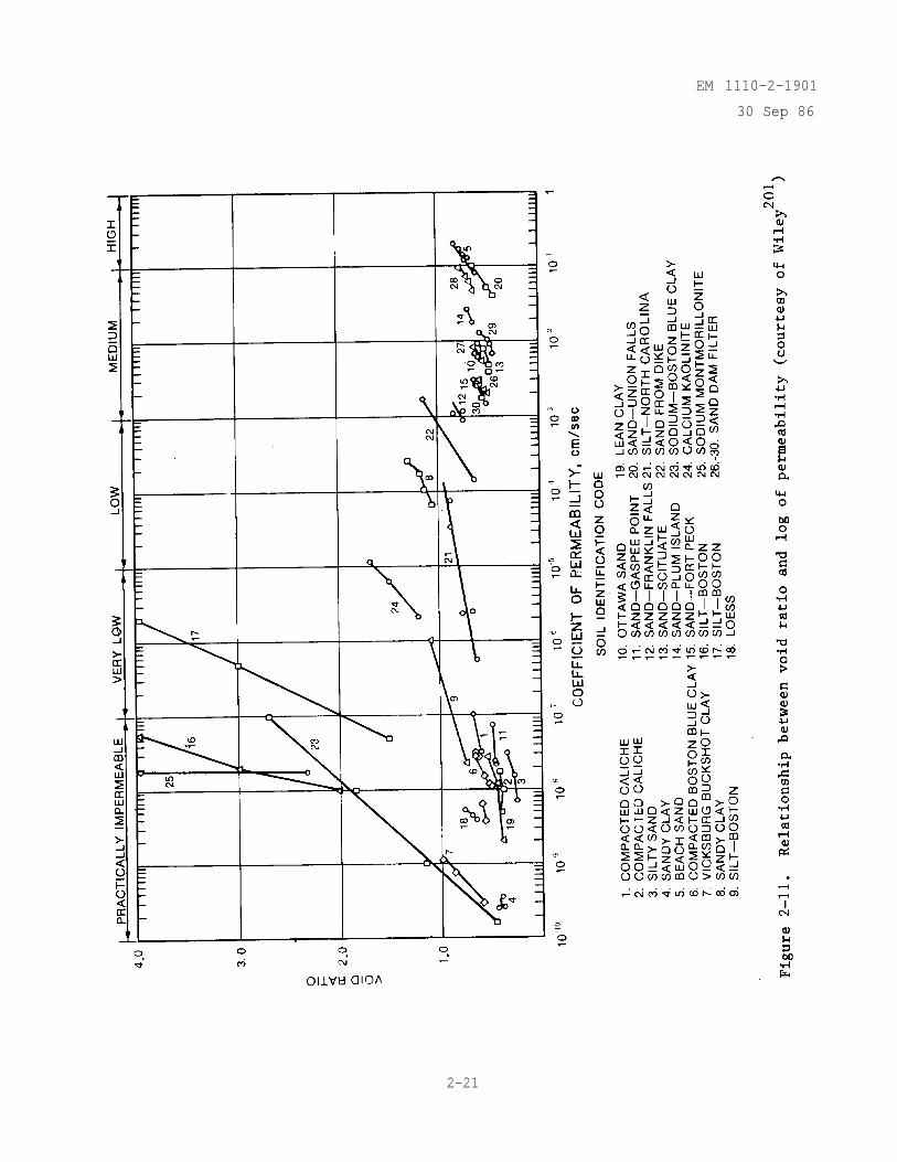
h. Void Ratio. The permeability increases as the void ratio increases.
(2-21)
where
e = void ratio
Vs = volume of solids
There are considerable laboratory test data, shown in figure 2-11, whichindicate that a plot of void ratio versus log of coefficient of permeabilityis frequently a straight line (Lambe and Whitman 1969).
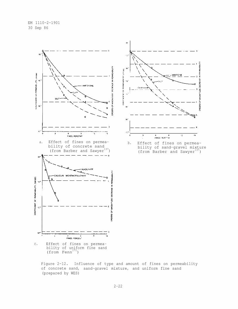
i. Amount and Type of Fines Present. The permeability of sands andgravels varies significantly with the amount and type of fines (materialsmaller than the No. 200 sieve) (Barber and Sawyer 1952; Fenn 1966; Youngerand Lim 1972; Strohm, Nettles, and Calhoun 1967; Nettles and Calhoun 1967, andLoudon 1952). As shown in figure 2-12a, the addition of 2.5 percent, by dryweight, silt fines to concrete sand results in an order of magnitude decreasein permeability (Barber and Sawyer 1952). The addition of 6.5 percent siltfines to concrete sand decreases the permeability two orders of magnitude.Similar results are obtained by the addition of somewhat larger amounts of clayand limestone fines to concrete sand. As shown in figure 2-12b, the additionof 2.0 percent silt fines to a sand-gravel mixture results in an order ofmagnitude decrease in permeability (Barber and Sawyer 1952). The addition of4.2 percent silt fines to sand-gravel mixture decreases the permeabilitytwo orders of magnitude. Similar results are obtained by the addition of
2-18
EM 1110-2-190130 Sep 86
2-19
EN 1110-2-1901
30 Sep 86
Figure 2-10. Krumbein and Sloss standard chart forvisual estimation of sphericity and roundness ofcohesionless soils (courtesy of W. H. Freeman
and Company198)
somewhat smaller amounts of clay and larger amounts of limestone, respec-tively, to a sand-gravel mixture. As shown in figure 2-12c, the addition ofabout 1 percent calcium montmorillonite fines to a uniform fine sand resultsin an order of magnitude decrease in permeability, while over 10 percentkaolinite fines would be required for a similar reduction in permeability(Fenn 1966).
j. Summary of Factors Influencing Permeability. The significantinfluence that various factors exert on the permeability emphasizes theimportance of duplicating field conditions when determining permeability inthe laboratory.
2-5. Indirect Methods for Determining Permeability.
a. Hazen's Equation. For uniform loose clean sands, classified SP inthe Unified Soil Classification System (U. S. Army Engineer Waterways Experi-ment Station 1960), the permeability may be estimated from the previouslygiven Hazen's equation (Taylor 1948)
(2-22)
where k is in cm per second and D10 is in cm.
2-20
EM 1110-2-1901
30 Sep 86
2-21
EM 1110-2-190130 Sep 86
a. Effect of fines on permea-bility of concrete sand(from Barber and Sawyer137)
c. Effect of fines on permea-bility of uniform fine sand(from Fenn171)
b. Effect of fines on permea-bility of sand-gravel mixture(from Barber and Sawyer137)
Figure 2-12. Influence of type and amount of fines on permeabilityof concrete sand, sand-gravel mixture, and uniform fine sand(prepared by WES)
2-22
EM 1110-2-190130 Sep 86
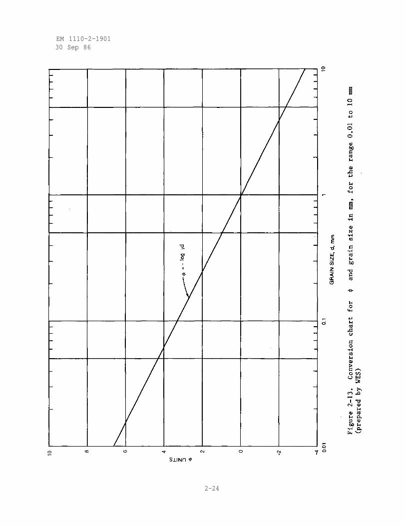
b. Masch and Denny Method. For uniform or nonuniform dense clean sands,classified SP or SW in the Unified Soil Classification System (U. S. ArmyEngineer Waterways Experiment Station 1960), the permeability may be estimatedfrom an empirical method developed by Masch and Denny 1966, and Denny 1965.The gradation curve is plotted in Krumbein 4 units (Krumbein and Pettijohn1938) (using the chart in figure 2-13) as shown in figure 2-14 where
(2-23)
where
= phi scale units used to describe grain size distribution
d = grain size diameter in mm
The inclusive standard deviation is used as a measure of the spread of thegradation curve where (Masch and Denny 1966)
where
= inclusive standard deviation
d16 = grain size in units at which 16 percent is finer
d84 = grain size in units at which 84 percent is finer
d5 = grain size in units at which 5 percent is finer
d95 = grain size in units at which 95 percent is finer
(2-24)
2-23
EM 1110-2-190130 Sep 86
2-24
EM 1110-2-1901
30 Sep 86
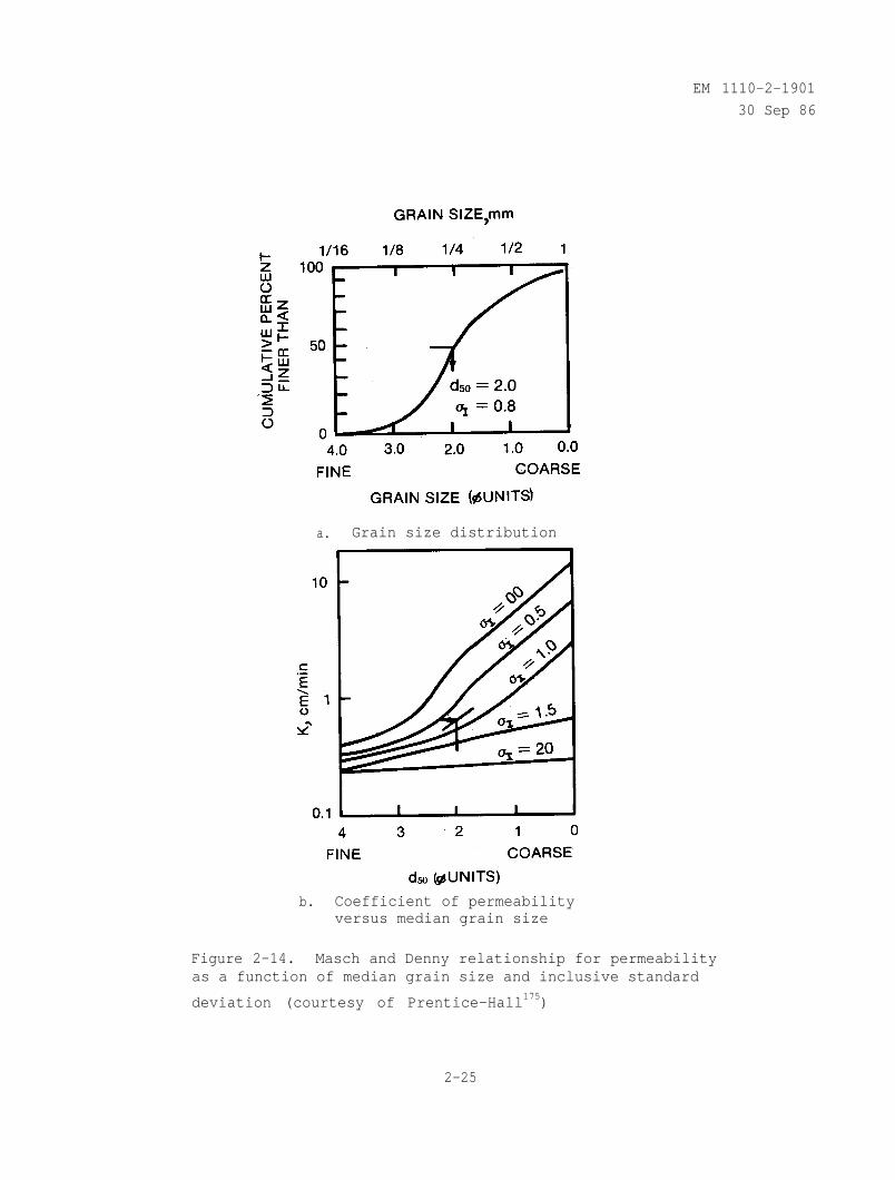
a. Grain size distribution
b. Coefficient of permeabilityversus median grain size
Figure 2-14. Masch and Denny relationship for permeabilityas a function of median grain size and inclusive standard
deviation (courtesy of Prentice-Hall175)
2-25
EM 1110-2-1901
30 Sep 86
The median grain size, d50 in units, is determined from the gradation
curve as shown in figure 2-14a. Then knowing and d50 , the coefficient
of permeability in cm per minute can be obtained from figure 2-14b (Freeze andCherry 1979).
c. Kozeny-Carman Equation. For uniform loose to dense clean sandsclassified SP in the Unified Soil Classification System (U. S. Army EngineerWaterways Experiment Station 1960), the permeability may be estimated usingthe Kozeny-Carman equation (Loudon 1952 and Perloff and Baron 1976)
(2-25)
where
k = coefficient of permeability
= unit weight of fluid
e = void ratio
Cs = shape factor corresponding to a particular flow channel
To = tortuosity factor related to the degree of sinuous flow
sS = specific surface (surface area of solids/volume of solids)
µ = coefficient of viscosity of fluid
For sands and silt-sized (finer than 0.074 mm and coarser than 0.005 mm)
particles CsTo2 = 5 is a good approximation (Perloff and Baron 1976). The
specific surface may be obtained from (Loudon 1952)
(2-26)
where
s s = specific surface
A = angularity factor
X1 = percentage of total soil sample between adjacent sieves expressedas a decimal
sl = specific surface of spheres uniformly distributed in size betweenthe mesh sizes of adjacent sieves
2-26
EM 1110-2-1901
30 Sep 86
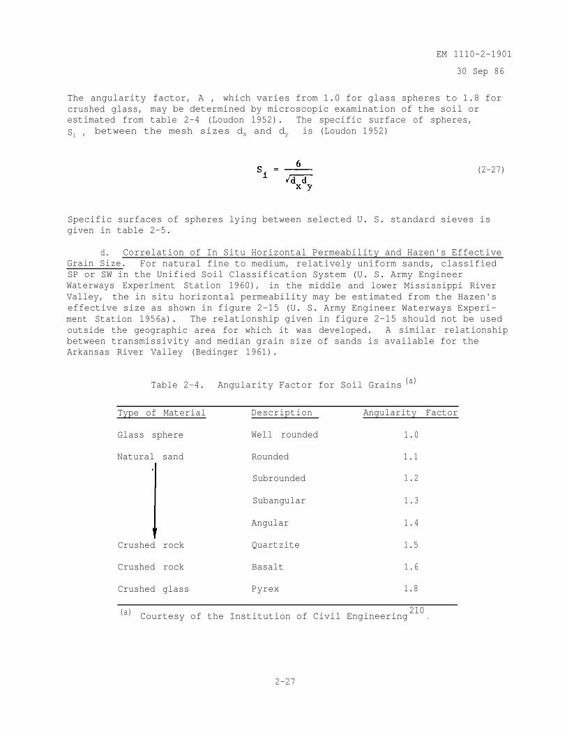
The angularity factor, A , which varies from 1.0 for glass spheres to 1.8 forcrushed glass, may be determined by microscopic examination of the soil orestimated from table 2-4 (Loudon 1952). The specific surface of spheres,Si , between the mesh sizes dx and dy is (Loudon 1952)
(2-27)
Specific surfaces of spheres lying between selected U. S. standard sieves isgiven in table 2-5.
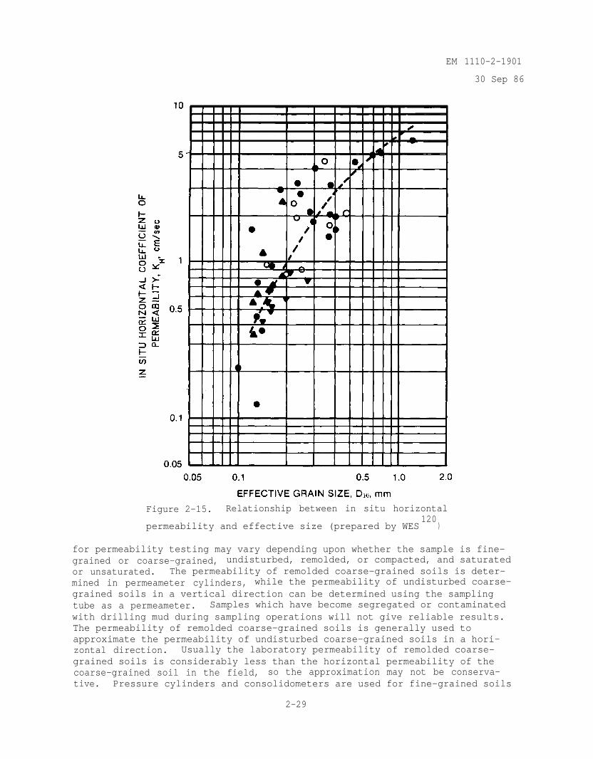
d. Correlation of In Situ Horizontal Permeability and Hazen's EffectiveGrain Size. For natural fine to medium, relatively uniform sands, classifiedSP or SW in the Unified Soil Classification System (U. S. Army EngineerWaterways Experiment Station 1960), in the middle and lower Mississippi RiverValley, the in situ horizontal permeability may be estimated from the Hazen'seffective size as shown in figure 2-15 (U. S. Army Engineer Waterways Experi-ment Station 1956a). The relationship given in figure 2-15 should not be usedoutside the geographic area for which it was developed. A similar relationshipbetween transmissivity and median grain size of sands is available for theArkansas River Valley (Bedinger 1961).
Table 2-4. Angularity Factor for Soil Grains (a)
Type of Material Description Angularity Factor
Glass sphere Well rounded 1.0
Natural sand
Crushed rock
Rounded
Subrounded
Subangular
Angular
Quartzite
1.1
1.2
1.3
1.4
1.5
Crushed rock Basalt 1.6
Crushed glass Pyrex 1.8
(a) Courtesy of the Institution of Civil Engineering210
.
2-27
EM 1110-2-1901
30 Sep 86
Table 2-5. Specific Surface of Spheres Lying Between
Selected U. S. Standard Sieve Sizes (a)
U. S. Standard Sieve Specific Surface (b)
Numbers 1/cm
4 to 6 3826 to 8 5388 to 10 69610 to 16 98516 to 20 152420 to 30 217830 to 40 308040 to 50 431850 to 70 608970 to 100 8574
100 to 140 12199140 to 200 17400
(a) Prepared by WES.(b)
e. Computation of Permeability from Consolidation Test. The coeffi-cient of permeability of normally consolidated clays and silts can be computedfrom the consolidation test using the relationship (Lambe 1951 and Olson andDaniel 1979)
(2-28)
where
cV = coefficient of consolidation
a v = coefficient of compressibility
eo = initial void ratio
2-6. Laboratory Methods for Determining Permeability.
a. General. Laboratory tests described in EM 1110-2-1906 can be usedto determine the coefficient of permeability of a soil, Unless otherwiserequired, the coefficient of permeability shall be determined using deaireddistilled water and completely saturated soil specimens. The apparatus used
2-28
EM 1110-2-1901
30 Sep 86
Figure 2-15. Relationship between in situ horizontal
permeability and effective size (prepared by WES120
)
for permeability testing may vary depending upon whether the sample is fine-grained or coarse-grained, undisturbed, remolded, or compacted, and saturatedor unsaturated. The permeability of remolded coarse-grained soils is deter-mined in permeameter cylinders, while the permeability of undisturbed coarse-grained soils in a vertical direction can be determined using the samplingtube as a permeameter. Samples which have become segregated or contaminatedwith drilling mud during sampling operations will not give reliable results.The permeability of remolded coarse-grained soils is generally used toapproximate the permeability of undisturbed coarse-grained soils in a hori-zontal direction. Usually the laboratory permeability of remolded coarse-grained soils is considerably less than the horizontal permeability of thecoarse-grained soil in the field, so the approximation may not be conserva-tive. Pressure cylinders and consolidometers are used for fine-grained soils
2-29
EM 1110-2-1901
30 Sep 86
in the remolded or undisturbed state. Fine-grained soils can be tested withthe specimen oriented to obtain the permeability in either the vertical orhorizontal direction.
b. Possible Errors. There are several possible errors in determiningpermeability in the laboratory (FM 1110-2-1906; Olson and Daniel 1979;and Mitchell, Guzikowski, and Villet 1978).
(1) Use of samples that are not representative of actual field condi-tions. This can be minimized by thorough field investigation, attention todetails (take undisturbed samples from test fills for determination of perme-ability of embankment materials, sampling along faults, fissures, clay seams,and sand partings for determination of permeability of the dam foundation),and by the use of large samples.
(2) Orientation of the in situ stratum to the direction of seepage flowis seldom duplicated in the laboratory. This can be overcome by obtaining thepermeability of the soil (embankment material and/or foundation) in both thevertical and horizontal direction.
(3) Incorrect hydraulic gradient used in the laboratory test. Thehydraulic gradient used in the laboratory should cover the range of expectedhydraulic gradient in situ. Where possible the hydraulic gradient should beselected so that the flow is laminar (straight line relationship between dis-charge versus hydraulic gradient) and Darcy's law will be applicable. It isusually not practical to achieve laminar flow for coarser soils, and thelaboratory test should be run at the hydraulic gradient anticipated in thefield.
(4) Air dissolved in the water. As water enters the specimen, smallquantities of air dissolved in the water will tend to collect as fine bubblesat the soil-water interface and reduce the permeability with increasing time.Permeability tests on saturated specimens should show no significant decreasein permeability with time if properly deaired distilled water is used. How-ever, if such a decrease in permeability occurs, then a prefilter, consistingof a layer of the same material as the test specimen, should be used betweenthe deaired distilled water reservoir and the test specimen to remove the airremaining in solution.
(5) Leakage along the sides of the permeameter can result in anincreased permeability. One major advantage of the triaxial compressionchamber for permeability tests is that the specimen is confined by a flexiblemembrane which is pressed tightly against the specimen by the chamber pressurethus reducing the possibility for leakage along the sides.
2-7. Origin, Occurrence, and Movement of Ground Water.
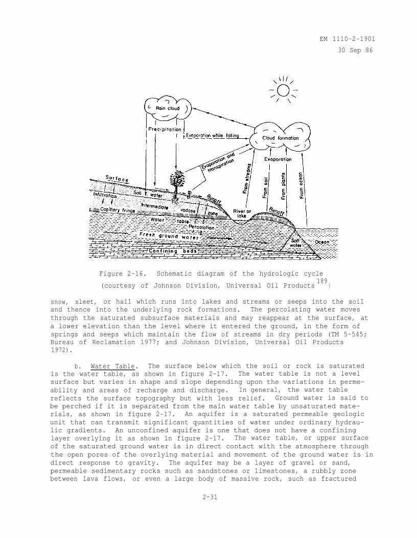
a. Hydrologic Cycle. Precipitation, runoff, storage, and evaporationof the earth's water follow an unending sequence called the hydraulic cycle,as shown in figure 2-16. Radiation from the sun evaporates water from theoceans into the atmosphere. The moisture is condensed and rises to form cloudformations. From these clouds, the earth receives precipitation of rain,
2-30
EM 1110-2-1901
30 Sep 86
Figure 2-16. Schematic diagram of the hydrologic cycle
(courtesy of Johnson Division, Universal Oil Products189
)
snow, sleet, or hail which runs into lakes and streams or seeps into the soiland thence into the underlying rock formations. The percolating water movesthrough the saturated subsurface materials and may reappear at the surface, ata lower elevation than the level where it entered the ground, in the form ofsprings and seeps which maintain the flow of streams in dry periods (TM 5-545;Bureau of Reclamation 1977; and Johnson Division, Universal Oil Products1972).
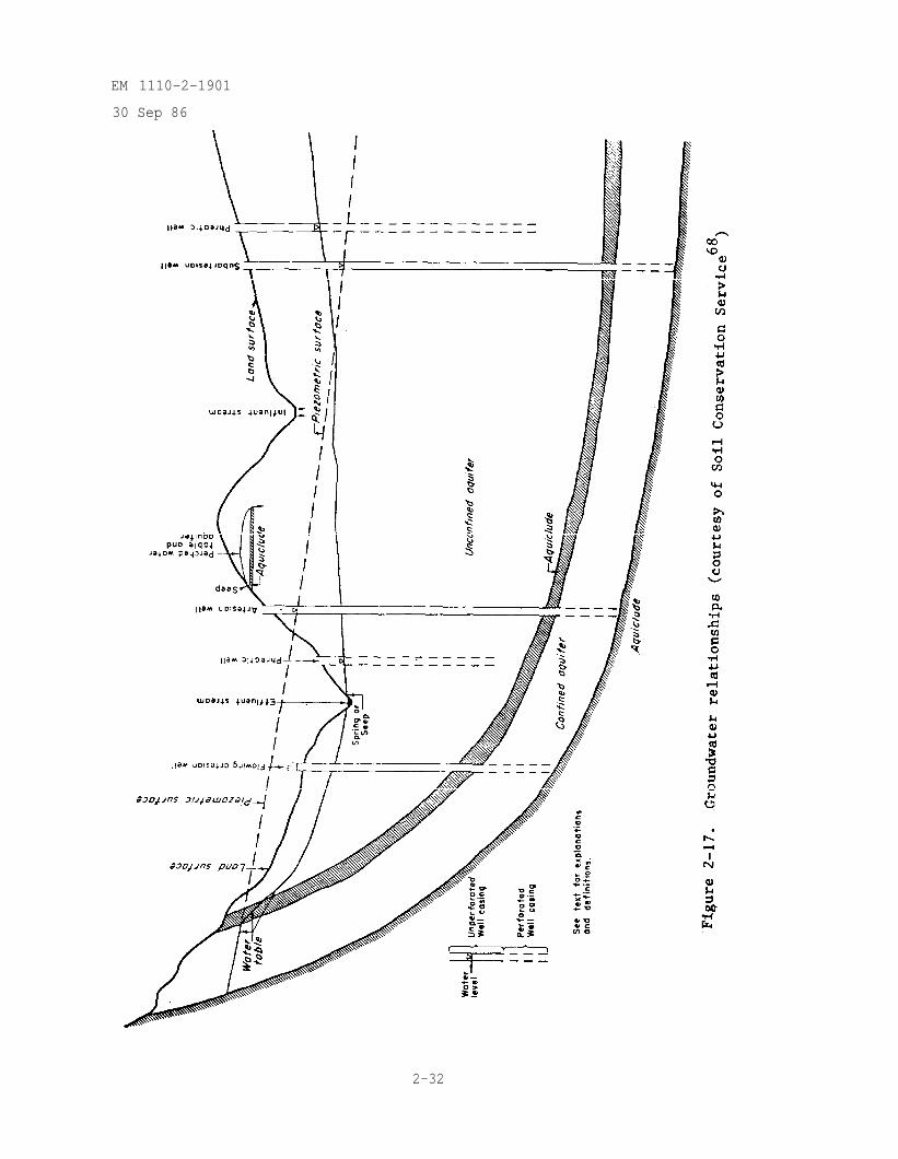
b. Water Table. The surface below which the soil or rock is saturatedis the water table, as shown in figure 2-17. The water table is not a levelsurface but varies in shape and slope depending upon the variations in perme-ability and areas of recharge and discharge. In general, the water tablereflects the surface topography but with less relief. Ground water is said tobe perched if it is separated from the main water table by unsaturated mate-rials, as shown in figure 2-17. An aquifer is a saturated permeable geologicunit that can transmit significant quantities of water under ordinary hydrau-lic gradients. An unconfined aquifer is one that does not have a confininglayer overlying it as shown in figure 2-17. The water table, or upper surfaceof the saturated ground water is in direct contact with the atmosphere throughthe open pores of the overlying material and movement of the ground water is indirect response to gravity. The aquifer may be a layer of gravel or sand,permeable sedimentary rocks such as sandstones or limestones, a rubbly zonebetween lava flows, or even a large body of massive rock, such as fractured
2-31
EM 1110-2-1901
30 Sep 86
2-32
EM 1110-2-1901
30 Sep 86
granite, which has sizable openings. An aquiclude is a saturated geologicunit that is incapable of transmitting significant quantities of water underordinary hydraulic gradients as shown in figure 2-17. A confined or artesianaquifer has an overlying confining layer of lower permeability than the aqui-fer and has only an indirect or distant connection with the atmosphere as.shown in figure 2-17. The water in the artesian aquifer is under pressure andif the aquifer is penetrated by a tightly cased well or a piezometer, thewater will rise above the bottom of the confining layer to an elevation atwhich it is in balance with atmospheric pressure. If this elevation isgreater than that of the land surface at the well, artesian water will flowfrom the well as shown in figure 2-17. The imaginary surface, conforming tothe elevations to which water will rise in wells penetrating an artesianaquifer, is the piezometric surface as shown in figure 2-17 (Soil ConservationService 1978, TM 5-545, Bureau of Reclamation 1977, Freeze and Cherry 1979,and Anonymous 1980).
2-8. Field Methods for Determining Permeability.
a. General. In sands it is difficult to obtain undisturbed soilsamples for laboratory testing and the structure (void ratio, stratification,etc.) has an important influence on-permeability. Therefore, field tests fordetermining permeability are necessary. Because sampling operations do notnecessarily indicate the relative perviousness of foundations containing largeamounts of gravelly materials, field pumping tests are required to determinethe foundation permeability for dams where positive measures are not proposedto completely cut off underseepage in the gravelly formations.
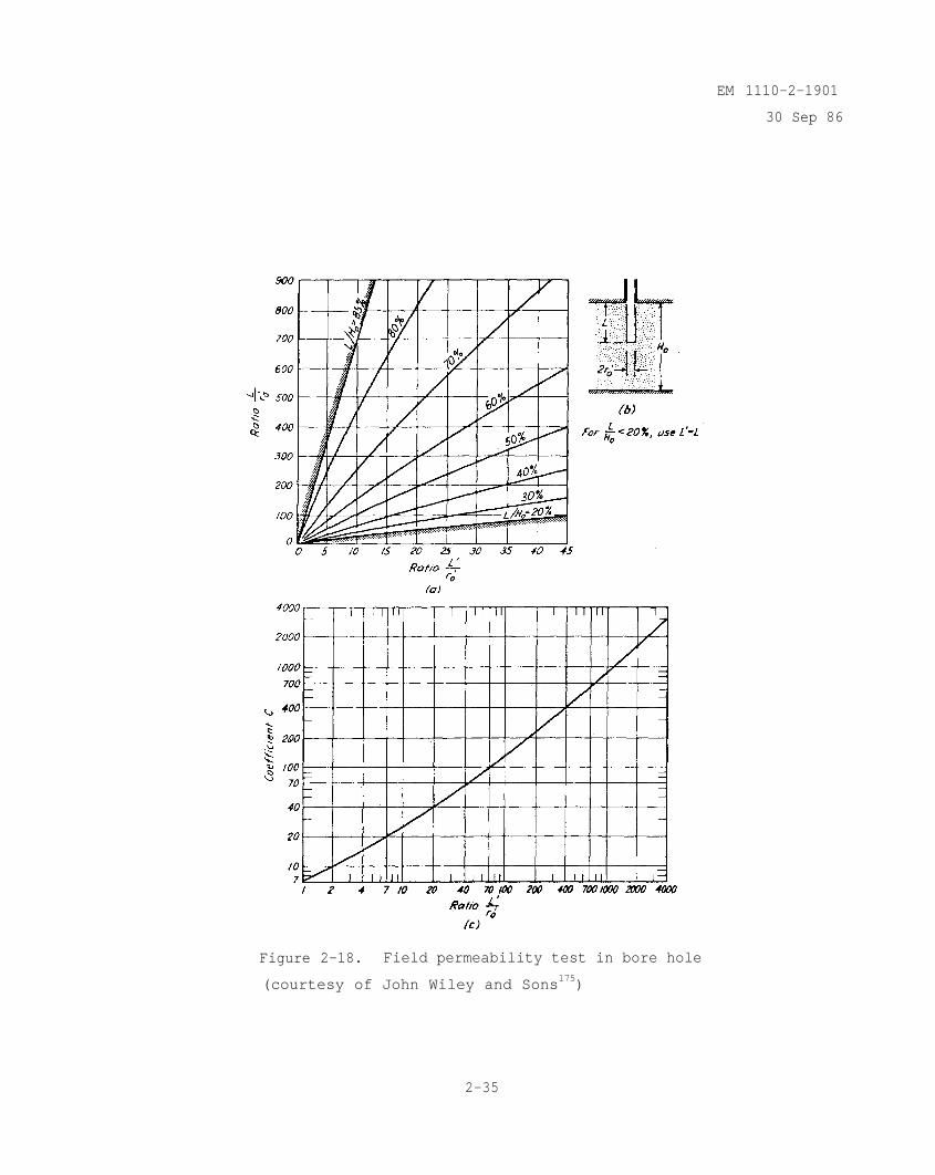
b. Test Pits and Bore Hole Tests.. In sands and gravels above theground-water level, field tests are normally carried out by measuring the down-ward seepage from test pits or shallow boreholes (Cedergren 1977). Below theground-water table information about the order of magnitude and variability ofthe coefficient of permeability may be obtained by conducting falling headpermeability tests in the exploratory boring as drilling proceeds. The holeis cased from the ground surface to the top of the zone to be tested andextends without support for a suitable depth below the casing. If the per-vious stratum is not too thick, the uncased hole is extended throughout thefull thickness, otherwise the uncased hole penetrates only a part of thepervious stratum. Water is added to raise the water level in the casing andthen the water level descends toward its equilibrium position. The elevationof the water level is measured as a function of time and the coefficient ofpermeability is calculated (Terzaghi and Peck 1967).
(2-29)
where
k = coefficient of permeability
2-33
EM 1110-2-1901
30 Sep 86
A = inside cross-sectional area of casing
drop in water level in casing during time interval At
time interval
C = dimensionless quantity depending on shape of cylindrical hole anddepth of penetration into pervious zone (see figure 2-18)
= mean radius of hole below casing
= mean distance during time interval At from water level in casingto equilibrium water level in pervious zone
The falling head field permeability test often gives an observed permeabilitythat is too low because silt particles which are suspended in the water mayform a filter skin over the walls and bottom of the hole in the pervious mate-rial. The results of such tests are little more than an indication of theorder of magnitude of the in situ permeability. More reliable data areobtained from field pumping tests.
c. Field Pumping Tests. The most reliable method for determining insitu permeability is a field pumping test on a test well which fully pene-trates the aquifer. The test procedures for equilibrium (steady-state flow)and nonequilibrium (transient flow) are given in Appendix III to TM 5-818-5and Civil Works Engineer Letter 63-16 (U. S. Army Corps of Engineers 1963).The ratio of the horizontal to vertical permeability can be determined fromspecially conducted field pumping tests (Mansur and Dietrich 1965).
2-9. Chemical Composition of Ground Water and River (or Reservoir) Water.
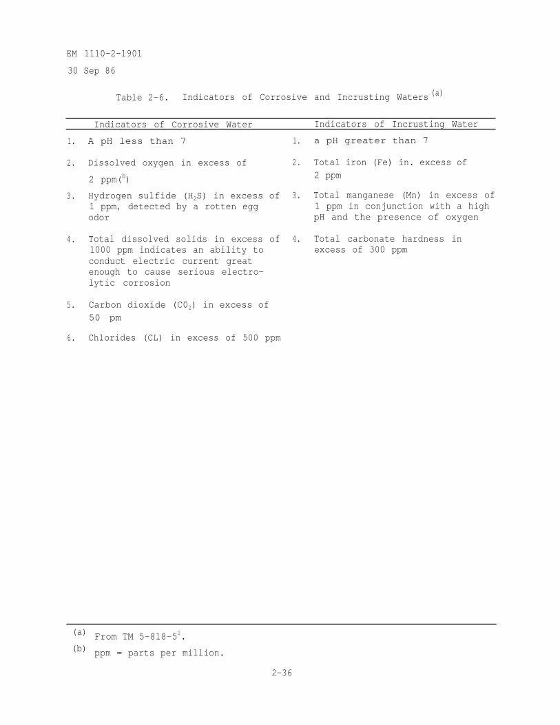
a. Ground Water. The chemical composition of the ground water is impor-tant because some ground waters are highly corrosive to metal screens, pipes,and pumps, or may contain dissolved minerals or carbonates which form incrus-tations in wells or filters and, with time, cause clogging and reduced effi-ciency of the dewatering or drainage system. Indications of corrosive andincrusting waters are given in table 2-6 (TM 5-818-5; and Johnson Division,Universal Oil Products 1972). General information concerning ground-waterproperties is available in an Atlas (Pettyjohn et al. 1979). Sampling, samplepreservation, and chemical analysis of ground water is covered in handbooks(Moser and Huibregtse 1976, and Environmental Protection Agency 1976).
b. River (or Reservoir) Water. The total amount of cations (calcium,magnesium, potassium, and sodium) in the river water (for dams not yet con-structed) and in the reservoir water (for existing dams) significantly influ-ences the erosion through a possible crack in the core of the dam (Perry 1975).Usually, as the total amount of cations in the eroding water decreases, theerodibility of the soil increases. For dams constructed of dispersive clay,the susceptibility of the dam to piping depends, in part, upon the total amountof cations in the seepage water (Perry 1979).
2-34
EM 1110-2-1901
30 Sep 86
Figure 2-18. Field permeability test in bore hole
(courtesy of John Wiley and Sons175)
2-35
EM 1110-2-1901
30 Sep 86
Table 2-6. Indicators of Corrosive and Incrusting Waters (a)
Indicators of Corrosive Water Indicators of Incrusting Water
1.
2.
A pH less than 7 1. a pH greater than 7
Dissolved oxygen in excess of
2 ppm(b)
3. Hydrogen sulfide (H2S) in excess of 3. Total manganese (Mn) in excess of1 ppm, detected by a rotten egg 1 ppm in conjunction with a highodor pH and the presence of oxygen
4. Total dissolved solids in excess of1000 ppm indicates an ability toconduct electric current greatenough to cause serious electro-lytic corrosion
5. Carbon dioxide (C02) in excess of50 pm
6. Chlorides (CL) in excess of 500 ppm
2. Total iron (Fe) in. excess of2 ppm
4. Total carbonate hardness inexcess of 300 ppm
(a) From TM 5-818-51.(b) ppm = parts per million.
2-36
EM 1110-2-1901
30 Sep 86
CHAPTER 3DETERMINATION OF PERMEABILITY OF ROCK
3-1. Permeabilities of Rock Masses. Permeability of rock, as with soil, is ameasure of the ease-with which fluids may travel through a medium under theinfluence of a driving force. The term "permeability," however, has severaldefinitions for describing the flow of water in rock masses.
a. Coefficient of Permeability. The engineer's coefficient, or Darcy'scoefficient, is normally referred to as simply the "coefficient of permeabil-ity." It is defined as the discharge velocity through a unit area under aunit hydraulic gradient and is dependent upon the properties of the medium, aswell as the viscosity and density of the fluid (Section 2-3.a.).
b. Intrinsic Permeability. The physicist's coefficient, or the intrin-sic permeability, is occasionally used in the determination of the hydraulicconductivity of a rock mass. It is defined as the volume of a fluid of unitviscosity passing through a unit cross section of a medium in unit time underthe action of a unit pressure gradient (Section 2-3.b.). The intrinsic perme-ability thus varies with the porosity of the medium and is independent of boththe viscosity and the density of the fluid.
c. Equivalent Permeability. The complex system of interconnected voidspace in a rock mass may be described in terms of an equivalent porous con-tinuum, and the flow assumed to occur uniformly throughout the mass ratherthan within individual passageways. Under these assumptions the term equiva-lent permeability is used to describe the permeability of a rock mass.\
d. Parallel Plate Permeability. The permeability of a fissure or afissure set is occasionally determined by modeling the rock mass conditionswith parallel plates. The parallel plate permeability can be computed fromthe value of the aperture between the plates (Ziegler 1976) and this perme-ability provides inferences for use in thecomputed parallel plate permeabilities haslaboratory tests (Snow 1965).
modeled rock mass. The accuracy ofbeen verified consistently with
e. Fissure Permeability. Fissure permability is the permeability ofan individual fissure or a set of fissures and, whether measured in thelaboratory or in the field, is determined using the parallel plate permeabilitytheory. Fissure permeability is determined using an equivalent parallel plateaperture, rather than the actual fissure aperture. This in effect incor-porates roughness into the parallel plate law.
3-2. Flow Characteristics in Rock Masses. The determination of the perme-ability of a rock mass, whether it be a rock slope, dam foundation, or damabutment, can only be accomplished after certain criteria are defined orspecified.
a. Continuum Approximations. From an overall regional point of view,most rock masses may be treated as continua, for all practical purposes. Oneof the primary considerations in selecting the continuum approach,-for evalu-ating the permeability of a rock mass, is the relative size, frequency, and
3-1
EM 1110-2-1901
30 Sep 86
orientation of the inherent discontinuities in the rock mass, compared withthe size of the area of interest or area under study. If the flow charac-teristics of a rock mass are to be treated as those of continua, the net vari-ation in flow over the study area should be relatively small, and the frequencyand orientation of the discontinuities should be such that they provide anoverall averaging effect on the flow with respect to the area of interest.
b. Discontinuum Approximations. As areas of investigation becomesmaller and smaller, i.e. more specific, the inherent discontinuities in rockmasses start to play larger and larger roles in the interpretation of ground-water flow and its path of movement. The permeabilities or relative perme-abilities of individual fissures and fissure systems are important for esti-mating the amount of seepage into various sections of underground excavationssuch as powerhouse tunnels or diversions , or through specific strata in a damfoundation or abutment. Discontinuum approximations of permeability are nor-mally used when the flow in the area of investigation is governed either by asingle fissure or by a fissure system.
(1) Single Fissure Flow. The permeability of single fissures can bevery important in karstic terrains, basalt, or rhyolite flows, or in areaswhere tunnels are driven through faulted zones. The flow through a singlefissure, under certain geologic conditions, can be the key to estimating theseepage through a dam foundation or abutment, or for determining the bestroute for a proposed tunnel.
(2) Flow Through Fissure Systems. Fissure systems such as joints,fractures, and bedding planes can yield, or contribute to, unpredictable flowpaths, seepage patterns, and uplift pressures. The permeability of fissuresystems should be evaluated by a discontinuum method of analysis when thesize, frequency, and orientation of such systems make a continuum approach tothe area under investigation unrealistic.
c. Ground-water Velocity. Flow of water in rock masses is generallyconsidered to be governed by one of two laws. Under conditions of laminarflow, Darcy's law, previously presented as equation 2-1 in Chapter 2 is assumedto govern the flow. For turbulent flow conditions in rock there is a nonlinearflow velocity versus hydraulic gradient relationship and equations presented byForchheimer (1914) and Missbach (1937) are assumed to govern the flow. TheMissbach law is the most convenient to analyze and it takes either oftwo forms,
(3-1)
or
3-2
(3-2)
EM 1110-2-1901
30 Sep 86
where
m and = degrees of nonlinearity
k' and B' = turbulent coefficients of permeability
Since the two equations are identical, resolving them indicates that m =
and The use of the above laws, however, is usually restrictedto a homogeneous, isotropic, porous continuum. Since in soil and rock massesthere are complex systems of interconnected void spaces, an equivalent ratherthan an absolute permeability should be determined. The coefficient of equiv-alent permeability from the continuum approach assumes that flow occurs uni-formly throughout the mass rather than within individual passageways. There-fore, for equivalent permeability, Darcy's law and Missbach's law are written,respectively,
(3-3)
and
(3-4)
where
ke = laminar equivalent permeability
turbulent equivalent permeability
The continuum approach, in some cases, is not applicable and therefore, thediscontinuum method of analysis for evaluating an equivalent permeabilityshould be used. Formulae for the discontinuum analysis for equivalentpermeability are presented later with various other methods of analysis.
3-3. Methods for Determining Rock Mass Permeability. Numerous methods havebeen developed for determining or estimating rock mass permeabilities. All ofthe available testing, as well as analytical techniques should be consideredand evaluated for each individual study, in order to optimize the advantagesand minimize the disadvantages inherent within each method for determining thepermeability of a rock mass.
a. Laboratory Permeability Tests. Laboratory permeability tests areused for evaluating the permeability of rock cores or samples, determining theflow characteristics of rock fissures, and performing parametric studies ofthe factors affecting the permeability of rock masses. Laboratory testmethods for permeability provide a convenient research and evaluation tool
3-3
EM 1110-2-1901
30 Sep 86
because a variety of parameters may be controlled and varied to yield a broadspectrum of conditions which may be encountered in a rock mass.
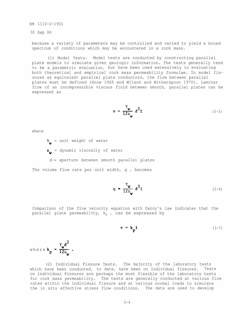
(1) Model Tests. Model tests are conducted by constructing parallelplate models to simulate given geologic information. The tests generally tendto be a parametric evaluation, but have been used extensively in evaluatingboth theoretical and empirical rock mass permeability formulae. To model fis-sures as equivalent parallel plate conductors, the flow between parallelplates must be defined (Snow 1965 and Wilson and Witherspoon 1970). Laminarflow of an incompressible viscous fluid between smooth, parallel plates can beexpressed as
where
= unit weight of water
= dynamic viscosity of water
d = aperture between smooth parallel plates
The volume flow rate per unit width, q , becomes
(3-5)
(3-6)
Comparison of the flow velocity equation with Darcy's law indicates that theparallel plate permeability, kp , can be expressed by
(3-7)
where
(2) Individual Fissure Tests. The majority of the laboratory testswhich have been conducted, to date, have been on individual fissures. Testson individual fissures are perhaps the most flexible of the laboratory testsfor rock mass permeability. The tests are generally conducted at various flowrates within the individual fissure and at various normal loads to simulatethe in situ effective stress flow conditions. The data are used to develop
3-4
EM 1110-2-1901
30 Sep 86
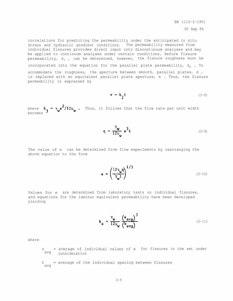
correlations for predicting the permeability under the anticipated in situstress and hydraulic gradient conditions. The permeability measured fromindividual fissures provides direct input into discontinuum analyses and maybe applied to continuum analyses under certain conditions. Before fissurepermeability, kj , can be determined, however, the fissure roughness must be
incorporated into the equation for the parallel plate permeability, kp . To
accommodate the roughness, the aperture between smooth, parallel plates, d ,is replaced with an equivalent parallel plate aperture, e . Thus, the fissurepermeability is expressed by
(3-8)
where Thus, it follows that the flow rate per unit widthbecomes
(3-9)
The value of e can be determined from flow experiments by rearranging theabove equation to the form
(3-10)
Values for e are determined from laboratory tests on individual fissures,and equations for the laminar equivalent permeability have been developedyielding
(3-11)
where
eavg
= average of individual values of e for fissures in the set underconsideration
bavg
= average of the individual spacing between fissures
3-5
EM 1110-2-1901
30 Sep 86
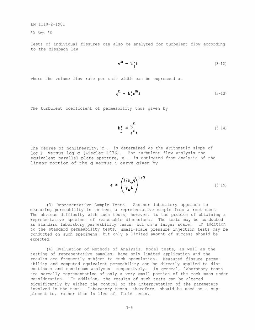
Tests of individual fissures can also be analyzed for turbulent flow accordingto the Missbach law
(3-12)
where the volume flow rate per unit width can be expressed as
The turbulent coefficient of permeability thus given by
(3-13)
(3-14)
The degree of nonlinearity, m , is determined as the arithmetic slope oflog i versus log q (Ziegler 1976). For turbulent flow analysis theequivalent parallel plate aperture, e , is estimated from analysis of thelinear portion of the q versus i curve given by
(3-15)
(3) Representative Sample Tests. Another laboratory approach tomeasuring permeability is to test a representative sample from a rock mass.The obvious difficulty with such tests, however, is the problem of obtaining arepresentative specimen of reasonable dimensions. The tests may be conductedas standard laboratory permeability tests, but on a larger scale. In additionto the standard permeability tests, small-scale pressure injection tests may beconducted on such specimens, but only a limited amount of success should beexpected.
(4) Evaluation of Methods of Analysis. Model tests, as well as thetesting of representative samples, have only limited application and theresults are frequently subject to much speculation. Measured fissure perme-ability and computed equivalent permeability can be directly applied to dis-continuum and continuum analyses, respectively. In general, laboratory testsare normally representative of only a very small portion of the rock mass underconsideration. In addition, the results of such tests can be alteredsignificantly by either the control or the interpretation of the parametersinvolved in the test. Laboratory tests, therefore, should be used as a sup-plement to, rather than in lieu of, field tests.
3-6
EM 1110-2-1901
30 Sep 86
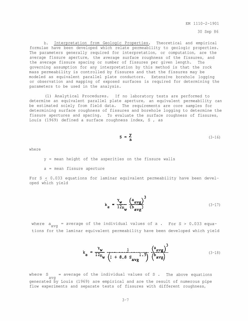
b. Interpretation from Geologic Properties. Theoretical and empiricalformulae have been developed which relate permeability to geologic properties.The parameters generally required for interpretation, or computation, are theaverage fissure aperture, the average surface roughness of the fissures, andthe average fissure spacing or number of fissures per given length. Thegoverning assumption for any interpretation by this method is that the rockmass permeability is controlled by fissures and that the fissures may bemodeled as equivalent parallel plate conductors. Extensive borehole loggingor observation and mapping of exposed surfaces is required for determining theparameters to be used in the analysis.
(1) Analytical Procedures. If no laboratory tests are performed todetermine an equivalent parallel plate aperture, an equivalent permeability canbe estimated solely from field data. The requirements are core samples fordetermining surface roughness of fissures and borehole logging to determine thefissure apertures and spacing. To evaluate the surface roughness of fissures,Louis (1969) defined a surface roughness index, S , as
(3-16)
where
y = mean height of the asperities on the fissure walls
a = mean fissure aperture
For S < 0.033 equations for laminar equivalent permeability have been devel-oped which yield
(3-17)
where aavg= average of the individual values of a . For S > 0.033 equa-
tions for the laminar equivalent permeability have been developed which yield
(3-18)
where Savg
= average of the individual values of S . The above equations
generated by Louis (1969) are empirical and are the result of numerous pipeflow experiments and separate tests of fissures with different roughness,
3-7
EM 1110-2-1901
30 Sep 86
modeled as openings between parallel slabs of concrete. In addition to laminarflow formulae, equations may be developed for turbulent flow for both thehydraulically smooth and the completely rough flow regimes.
(2) Evaluation of Method of Analysis. Comparisons of permeabilityinterpreted from geologic properties with permeability measured by othermethods have indicated the potential for large differences between the com-puted and the actual permeability. Interpretations of permeability from fis-sure properties are made difficult by obvious problems in measuring fissureapertures and roughness.' Natural fissures can have complex surficial geom-etries and can only be observed in boreholes or exposed surfaces, which may bedisturbed during excavation. Potentially large discrepancies are possible, dueto the possibility of many fissures near the borehole being either exaggerated,constricted, or discontinuous, due to the disturbance during drilling. Whileinterpretation of permeability from geologic properties is theoretically pos-sible, the results should be used with caution.
c. Field Measurements. By far the most accurate and most reliabletechnique for determining the permeability of a rock mass is that of fieldtesting. The use of field tests results in larger volumes of the rock massbeing tested and the tests are performed under in situ conditions. Fieldtests have generally been limited to ground-water velocity measurements, pump-ing tests, and injection tests.
(1) Ground-water Velocity Measurements. The equivalent permeability canbe computed for a rock mass by measuring the ground-water velocity and thehydraulic gradient when certain criteria are met. It must be assumed thatsteady-state horizontal flow intersects the well and flow is governed byDarcy's law. There are several techniques available for measuring ground-watervelocity downhole as discussed below.
(a) Temperature Probes. The velocity of ground water moving through aborehole may be determined with the use of temperature probes or sensors. Suchdevices consist of a small heater strip or coil mounted beneath a thermistor.The amount of heat dissipated is a function of the ground-water velocity, andproperly calibrated, the devices can sense very low velocities (below1 ft/min). The directional components of flow may be obtained by rotation ofthe device or by the construction of orthogonal flow channels within the deviceitself.
(b) Flowmeters. When conditions of high ground-water flow rates areencountered, small horizontally mounted commercial flowmeters may be placeddownhole for measuring the velocity. The direction of flow may be determinedby varying the orientation of the flowmeter.
(c) Tracer Tests. Tracer tests involve the injection of an inert solu-tion, or tracer, into an existing flow field via a borehole or well. Tracertests are often desirable because they are passive-type tests and do not placeunnatural stress conditions on the flow system. The dilution rate of thetracer at the injection well or its time of travel to another well can be usedto calculate the ground-water velocity and ultimately the permeability. Detec-tion of the tracer, or concentration measurements, can be made by either
3-8
EM 1110-2-1901
30 Sep 86
manual or probe sampling. Generally, the probe method of sampling is desirableto avoid any disturbance to the flow system due to sample extraction. The"travel time" tracer tests normally involve large portions of the rock mass,and thus have the advantage of averaging the effects of exceptionally high- orlow-permeability zones within the mass. The dilution method of testing isparticularly applicable to determining permeability profiles within a singleborehole by injection of the tracer into borehole sections isolated by packers.Commonly used tracers are radioisotopes, salt solution, and fluorescent dyes.
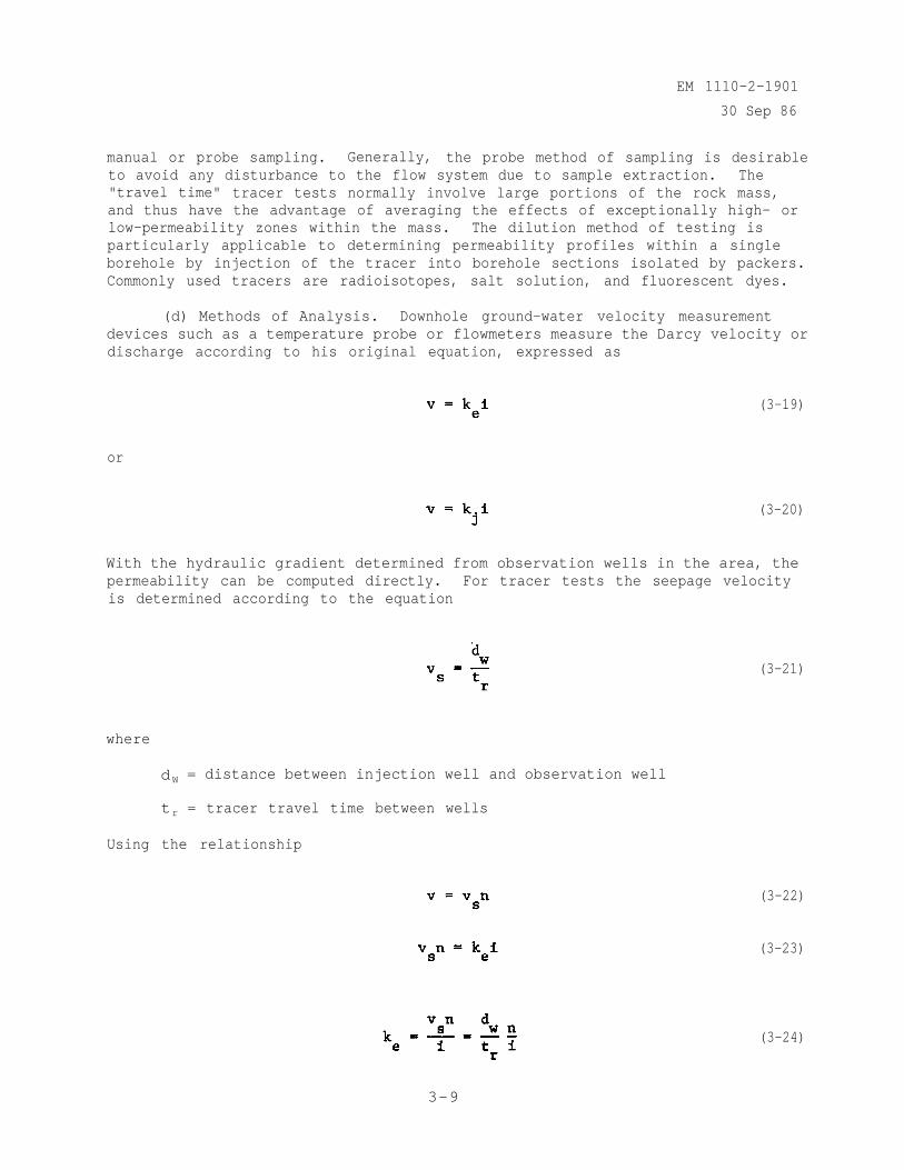
(d) Methods of Analysis. Downhole ground-water velocity measurementdevices such as a temperature probe or flowmeters measure the Darcy velocity ordischarge according to his original equation, expressed as
(3-19)
or
(3-20)
With the hydraulic gradient determined from observation wells in the area, thepermeability can be computed directly. For tracer tests the seepage velocityis determined according to the equation
where
dW = distance between injection well and observation well
tr = tracer travel time between wells
Using the relationship
(3-21)
(3-22)
(3-23)
(3-24)
3-9
EM 1110-2-1901
30 Sep 86
In analyzing a tracer dilution test, the flow velocity, v , is related to therate at which the tracer concentration diminishes within the test section ofthe injection well. For an assumed homogeneous isotropic porous medium, thevelocity is determined from the following equation given by Lewis, Kriz, andBurgy (1966).
(3-25)
where
wd= well diameter
Cr = ratio of the final to the initial tracer concentration
td = dilution time period
Analysis of dilution tests in fractured and fissured rock masses is made byapplying the parallel plate analogy.
(2) Pumping Tests. Pumping tests have become an established means ofdetermining the permeability of hydraulic characteristics of water bearingmaterials. In a pumping test, water is pumped from a well normally at aconstant rate over a certain time period, and the drawdown of the water tableor piezometric head is measured in the well and in piezometers or observationwells in the vicinity. Since pumping tests, as with tracer tests, involvelarge volumes of the rock mass, they have the advantage of averaging theeffects of the inherent discontinuities, such as joints, fissures, fractures,etc. Most classical solutions for pump test data are based on the assumptionsthat the aquifers are homogeneous and isotropic, and that the flow is governedby Darcy's law. Applications of such solutions to interpretation of pumpingtests in rock masses have resulted in varying degrees of success. For caseswhere the normal solutions have proven to be unsuccessful or inadequate,mathematical models have been developed which are capable of modeling the flowregime in various types of rock masses. With pumping tests, the major dis-advantage is the period of time required to perform a test. Test durations ofone week or longer are not unusual when attempting to approach steady-stateflow conditions. Additionally, large diameter boreholes or wells are requiredsince the majority of the conditions encountered require the use of a downholepump. The analysis of pumping test results obtained from rock masses isgenerally completely analogous to the analyses used in classical soilmechanics. Since such analyses are well-documented, they will not be pre-sented here.
(3) Injection Tests. Injection tests, which are the reciprocal ofpumping tests, commonly involve the steady-state transmission of a fluid from aborehole into the surrounding medium. The permeability of a rock mass can berelated to the relationship between the injection pressure and the flow rate.Equations and techniques have been developed for both the steady-state and the
3-10
EM 1110-2-1901
30 Sep 86
unsteady-state conditions and for using either air or water for injection.Methods of analysis of pressure injection tests are presented in Appendix C.
(a) Water Pressure Tests. Water pressure tests, also known as packertests (in Europe they are called Lugeon tests) are normally conducted bypumping water at a constant pressure into a test section of a borehole andmeasuring the flow rate. Borehole test sections are commonly sealed off byone to four packers, with the use of one or two packers being the most widelyused technique. In comparison with a pumping test, a water pressure testaffects a relatively small volume of the surrounding medium, because frictionallosses in the immediate vicinity of the test section are normally extremelylarge. The test, however, is rapid and simple to conduct, and by performingtests within intervals along the entire length of a borehole, a permeabilityprofile can be obtained. Additionally, the water pressure test is normallyconducted in NX boreholes, and has the advantage of being conducted above orbelow the ground-water table.
(b) Air Pressure Tests. Air pressure tests are similar to water pres-sure tests except that air rather than water is used for the testing fluid.The air pressure test was developed for testing above the ground-water tableand has predominantly been used for testing areas of high permeability such asthose characteristic of rubblelike, fallback material adjacent to explosivelyexcavated craters in rock. In such areas, water pressure tests have beeninadequate due to an inability to provide water at a flow rate high enough topressurize the surrounding media. Air pressure tests have an unlimited supplyof testing fluid, as well as the advantage of a wide variety of high capacityair compressors. The disadvantage of such tests is that permeability equationsmust be modified for application to a compressible fluid and a conversion fromthe air permeability to a water permeability must be made to obtain usableresults.
(c) Pressure Holding Tests. Pressure holding or pressure drop tests areusually conducted in conjunction with water pressure tests. The test isanalogous to the falling head test used in soil mechanics; however, in rockthe test section is normally pressurized to a value above that of the statichead of water between the test zone and the ground surface. The pressures arenormally measured in the test section with a transducer, and pressures versustime are recorded. The pressure holding test offers the advantage of beingquick and simple to perform, as well as requiring significantly less waterthan that used in conventional constant pressure tests.
3-4. Applications of Rock Mass Permeability.
a. Assessment of Ground-water Movements. The permeability of a dam'sfoundation or abutments is one of the controlling factors in the movement ofground water; therefore,. a valid assessment is imperative. The rock masspermeability of the dam foundation or abutment has numerous applications, eachhaving potentially significant impact on the design or safety of thestructure.
(1) Seepage Patterns. Seepage patterns which are expected to developafter impoundment of a reservoir should be evaluated during the design phase of
3-11
EM 1110-2-1901
30 Sep 86
a dam. Seepage patterns which do actually develop after a reservoir is inoperation provide valuable data for an evaluation of the as-built performanceof any cutoff or relief measures, sources and exits of seepage, and input forplanning required remedial measures, such as additional cutoffs, drains, etc.In rock masses, generally, the overall trend of the seepage patterns can bedetermined by the continuum approach; however, in some cases, a detailedanalysis of a specific seepage problem requires the use of a discontinuumapproach.
(2) Flow Rates. Given the permeability and gradient, the flow rateacross a given area can be computed. With the effective porosity, the rate ofadvance of a seepage front can be determined. Ground-water flow rates arerequired for determining construction dewatering requirements for both surfaceand subsurface excavations, as well as the seepage losses through dam founda-tions and abutments.
b. Foundation and Abutment Drainage Requirements. The permeability ofa dam's foundation and abutments is the major factor involved in evaluatingdrainage requirements. Accurate and reliable rock mass permeability measure-ments are required in the design phase for determining the necessity for, andextent of, cutoff, vertical drains, drainage blankets, relief wells, etc.Postconstruction problems with leakage, excessive uplift pressures, etc., alsorequire an in-depth evaluation of the flow of the water in a foundation orabutment. Evaluations of drainage or relief requirements are generallydirected toward specific areas and, in most cases, while a continuum approachcan give satisfactory approximations, the discontinuum analysis is requiredfor describing the flow characteristics in details.
c. Grouting Requirements and Effectiveness. Consistent with determiningthe drainage requirements for a structure, the permeability is also useful forestimating the grouting requirements. In the design phase of a dam therequirements for cutoff or grouting, and drainage or relief, compliment eachother and are balanced to obtain a desired seepage pattern and uplift pressuredistribution beneath or within the structure. In foundations, and particularlyin abutments, permeability measurements can indicate possible solution chan-nels, faults, fissures, or other highly permeable zones which require grout-ing. If permeability tests are conducted at a given location, both before andafter a grouting operation, an evaluation of the grouting effectiveness can bemade. Such tests should be conducted as a matter of routine since they willeither establish a confidence level or indicate the need for additionalgrouting.
d. General Considerations. The application of rock mass permeabilityto seepage control methods and evaluations has become increasingly useful asmore complex methods of analysis evolve.
(1) Index Tests. The determination of rock mass permeability for damfoundations and abutments has historically been used more as an index testthan as an absolute test. As the state of the art advances this trend isgradually changing. While index tests are a valuable tool to the experiencedfoundation engineer, more complex methods of analysis are becoming available
3-12

EM 1110-2-1901
30 Sep 86
which allow a complete evaluation of the mechanisms involved as water flowsthrough a fractured or fissured rock mass.
(2) Continuum Analyses. The accuracy of continuum approximations ofpermeability is dependent upon the geology and the size of the area underconsideration. In general, continuum analyses provide average permeabilitiesor regional permeabilities in which the assumptions of isotropy and homogene-ity can be used in a gross sense. From a practical point of view the continuumapproach has been and continues to be a useful tool for evaluating rock masspermeability.
(3) Discontinuum Analyses. Recently the discontinuum approach todetermining permeability has become more and more promising. As techniques fordetermining individual fissure permeabilities advance, the availability ofbetter modeling techniques increases, and understanding of the influences oforientation, spacing, apertures, and surficial geometries of fissures and fis-sure sets increase, the discontinuum approach to determining rock mass perme-ability becomes more reliable.
3-13
EM 1110-2-1901
30 Sep 86
CHAPTER 4SEEPAGE PRINCIPLES
4-1. General Considerations. Seepage as used in this manual is defined asthe flow of water through homogeneous saturated soil under steady-state condi-tions. Additionally, the soil particles, soil structure, and water areassumed incompressible and flow obeys Darcy's law. Thus transient conditionssuch as a wetting front or other movement of water in unsaturated soil, con-solidation, and subsidence are not considered for analysis. Principles whichcharacterize movement of energy through conducting media also apply to themovement of water through soils. Seepage has been modeled for study by usingflow of electricity and heat. Both conditions are governed by Laplace's equa-tion in homogeneous media. As explained in Chapter 2, water moves from ahigher energy state to a lower energy state, and in seepage the difference inenergy states is the amount of energy required to move the water through thesoil, i.e., to overcome the soil's resistance to the flow of water. Chapter 4will consider factors controlling seepage, equations describing seepage,methods of determining pressure distribution and pressures at particular pointsin the soil, and seepage quantities. For example, in figure 4-1(a): What isthe uplift pressure at point 5? How much water will exit at point 8? Howfast? Will the sand at point 8 be eroded? If the sheet pile at point 6 isremoved, how will it affect pressure distribution beneath the dam?
4-2. Boundary Conditions.
a. Basis. The saturated soil which is considered for analysis must bedefined by boundaries, permeability of the soil, and heads imposed upon thewater. This section considers the types of boundaries which may define aparticular porous soil mass considered for analysis. The nature and locationof these boundaries are determined by a soils exploration program, assumptionsbased on engineering judgment and conditions imposed by the proposed design.Normally, simplifying assumptions are required in order to establish boundarieswhich will make analysis feasible. Generally, seepage analysis problemsassociated with dams will involve four possible types of boundaries (Harr1962). Examples of the four general types of boundary conditions are shown infigure 4-1.
b. Impervious Boundaries. The interface between the saturated, per-vious soil mass and adjacent materials such as a very low permeability soil orconcrete is approximated as an impervious boundary. It is assumed that no flowtakes place across this interface, thus flow in the pervious soil next to theimpervious boundary is parallel to that boundary. In figure 4-1, lines AB and1-8 are impervious boundaries.
c. Entrances and Exits. The lines defining the area where water entersor leaves the pervious soil mass are known as entrances or exits, respec-tively. Along these lines (O-l and 8-G in figure 4-1(a) and AD and BE infigure 4-1(b)) are lines of equal potential; that is, the piezometric level isthe same all along the line regardless of its orientation or shape. Flow isperpendicular to an entrance or exit. Entrances and exits are also calledreservoir boundaries (Harr 1962).
4-1
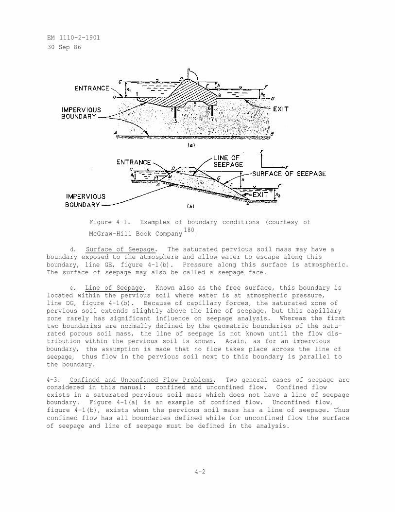
EM 1110-2-1901
30 Sep 86
Figure 4-1. Examples of boundary conditions (courtesy of
McGraw-Hill Book Company180
)
d. Surface of Seepage. The saturated pervious soil mass may have aboundary exposed to the atmosphere and allow water to escape along thisboundary, line GE, figure 4-1(b). Pressure along this surface is atmospheric.The surface of seepage may also be called a seepage face.
e. Line of Seepage. Known also as the free surface, this boundary islocated within the pervious soil where water is at atmospheric pressure,line DG, figure 4-1(b). Because of capillary forces, the saturated zone ofpervious soil extends slightly above the line of seepage, but this capillaryzone rarely has significant influence on seepage analysis. Whereas the firsttwo boundaries are normally defined by the geometric boundaries of the satu-rated porous soil mass, the line of seepage is not known until the flow dis-tribution within the pervious soil is known. Again, as for an imperviousboundary, the assumption is made that no flow takes place across the line ofseepage, thus flow in the pervious soil next to this boundary is parallel tothe boundary.
4-3. Confined and Unconfined Flow Problems. Two general cases of seepage areconsidered in this manual: confined and unconfined flow. Confined flowexists in a saturated pervious soil mass which does not have a line of seepageboundary. Figure 4-1(a) is an example of confined flow. Unconfined flow,figure 4-1(b), exists when the pervious soil mass has a line of seepage. Thusconfined flow has all boundaries defined while for unconfined flow the surfaceof seepage and line of seepage must be defined in the analysis.
4-2
EM 1110-2-1901
30 Sep 86
4-4. Laplace's Equation.
a. Seepage Analysis. In order to do a seepage analysis, a generalmodel describing the phenomena of seepage must be available. Supplied withspecific boundary conditions and soil properties, this model can be used todetermine head and flow distribution and seepage quantities. The Laplaceequation is the mathematical basis for several models or methods used inseepage analysis.
b. Basis of Laplace's Equation. Figure 4-2 shows a general seepagecondition from which an element is taken. Development of Laplace's equationdepends on six assumptions:
(1) Heads h1
and h2
are constant and thus flow is steady state.
(2) Water is incompressible.
(3) Volume of voids does not change--soil is incompressible.
(4) Flow is laminar--Darcy's law applies.
(5) The element has a dimension, dy , into the plane of the figurewhich gives an element volume but no flow takes place perpendicular to theplane of the figure, i.e., the flow is two-dimensional.
(6) The saturated pervious soil stratum is homogeneous. Fromfigure 4-2(b) let:
v ,vx z= components of discharge velocity in x and z directions,
respectively
hydraulic gradient in the x direction
hydraulic gradient in the z direction
(The minus sign indicates that gradient is in a direction opposite increasingpiezometric head.) Assumptions 1, 2, and 3 assure continuity of flow whichmeans that water entering the element per unit of time, q e (where qe = vx
dz dy + vz dx dy) equals water leaving the element per unit of time,
(where Setting
equal to gives:
4-3
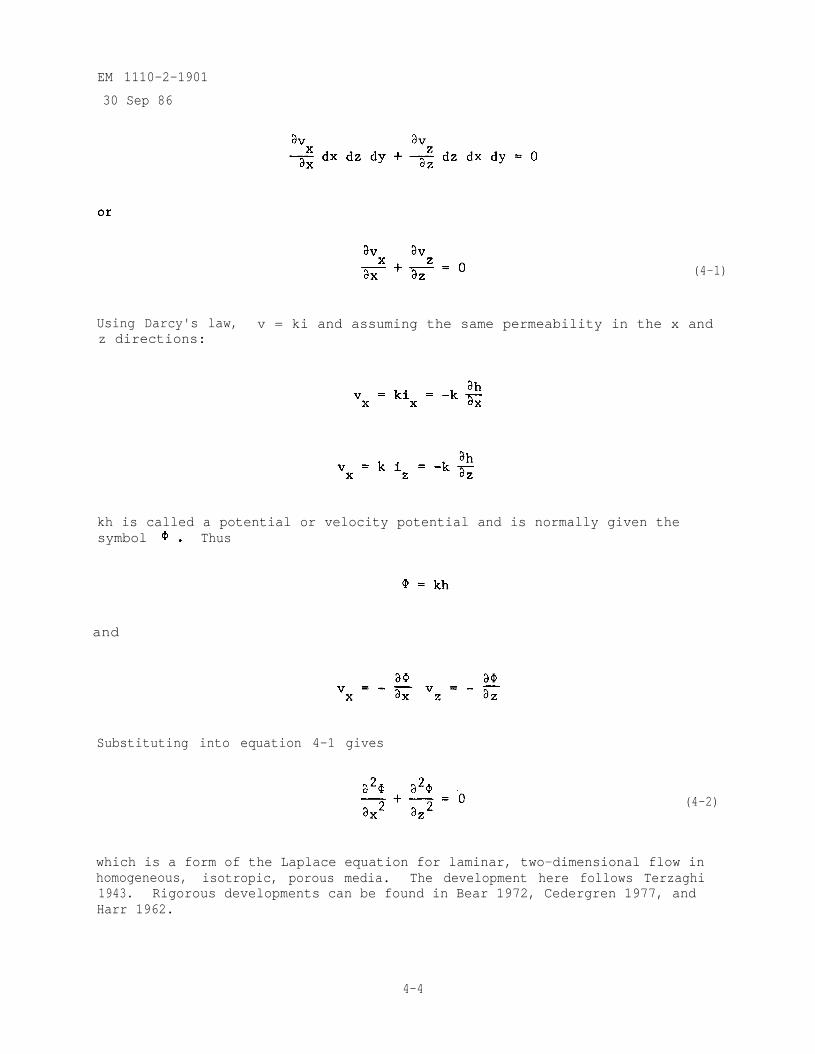
EM 1110-2-1901
30 Sep 86
(4-1)
Using Darcy's law, v = ki and assuming the same permeability in the x andz directions:
kh is called a potential or velocity potential and is normally given thesymbol Thus
and
Substituting into equation 4-1 gives
(4-2)
which is a form of the Laplace equation for laminar, two-dimensional flow inhomogeneous, isotropic, porous media. The development here follows Terzaghi1943. Rigorous developments can be found in Bear 1972, Cedergren 1977, andHarr 1962.
4-4
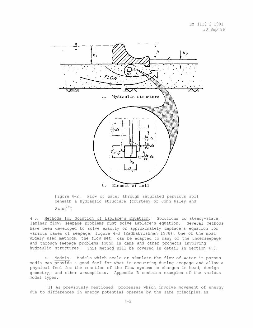
EM 1110-2-190130 Sep 86
Figure 4-2. Flow of water through saturated pervious soilbeneath a hydraulic structure (courtesy of John Wiley and
Sons274)
4-5. Methods for Solution of Laplace's Equation. Solutions to steady-state,laminar flow, seepage problems must solve Laplace's equation. Several methodshave been developed to solve exactly or approximately Laplace's equation forvarious cases of seepage, figure 4-3 (Radhakrishnan 1978). One of the mostwidely used methods, the flow net, can be adapted to many of the underseepageand through-seepage problems found in dams and other projects involvinghydraulic structures. This method will be covered in detail in Section 4.6.
a. Models. Models which scale or simulate the flow of water in porousmedia can provide a good feel for what is occurring during seepage and allow aphysical feel for the reaction of the flow system to changes in head, designgeometry, and other assumptions. Appendix B contains examples of the variousmodel types.
(1) As previously mentioned, processes which involve movement of energydue to differences in energy potential operate by the same principles as
4-5
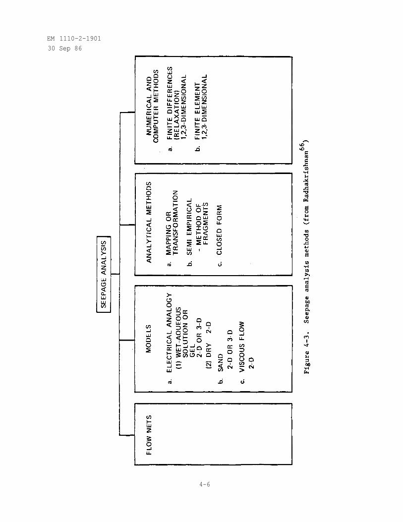
EM 1110-2-1901
30 Sep 86
4-6
EM 1110-2-1901
30 Sep 86
movement of confined ground water. These processes include electricity andheat flow which have been used as seepage analogies. Electrical analogies haveproven particularly useful in the study of three-dimensional problems and inproblems where geometric complexities do not allow adequate simplifyingassumptions for analytical methods. "Wet" electrical analogies normally use aconducting aqueous solution or gel to model the volume of the confined, satu-rated, porous soil. Wet models are well suited to projects where an irregularstructure penetrates a confined aquifer. By probing the gel or solution whena set potential or voltage is applied across it, electrical potential can bedetermined at various points of interest in the model aquifer (McAnear andTrahan 1972, Banks 1963, 1965). When field conditions can be characterized bya two-dimensional plan or section, conducting paper models may be used toinexpensively determine the effect of various configurations on the flow andpressures in the aquifer, figure 4-4 (Todd 1980).
(2) Sand models which may use prototype materials can provide informa-tion about flow paths and head at particular points in the aquifer. The sandor porous material may be placed underwater to provide a homogeneous condi-tion, or layers of different sand sizes may be used to study effects of inter-nal boundaries or layers. If the flow is unconfined and the same material isused for model and prototype, the capillary rise will not be scaled and mustbe compensated for in the model. Flow can be traced by dye injection andheads determined by small piezometers. Disadvantages include effects oflayering when the porous material is placed, difficulty in modeling prototypepermeability and boundary effects. Prickett (1975) provides examples of sandtank models and discusses applications, advantages, and disadvantages.
(3) Viscous flow models have been used to study transient flow (e.g.,sudden drawdown) and effects of drains. This method depends on the flow of aviscous fluid such as oil or glycerin between two parallel plates and is nor-mally used to study two-dimensional flow. As with sand models, dye can beused to trace flow lines.' Construction is normally complicated and operationrequires care since temperature and capillary forces affect the flow. Flowmust be laminar, which can be difficult to achieve at the boundaries or atsharp changes in boundary geometry.
b. Analytical Methods.
(1) Harr (1962) explains the use of transformations and mapping totransfer the geometry of a seepage problem from one complex plane to another.In this manner, the geometry of a problem may be taken from a plane where thesolution is unknown to a plane where the solution is known. While this methodhas been used to obtain solutions to general problems it is not frequentlyused for solutions to site-specific seepage problems since it requires the useof complex variable theory and proper choice of transformation functions.
(2) Pavlovsky (1936, 1956) developed an approximate method which allowsthe piecing together of flow net fragments to develop a flow net for the totalseepage problem. This method, termed the Method of Fragments, allows rathercomplicated seepage problems to be resolved by breaking them into parts,analyzing flow patterns for each, and reassembling the parts to provide an
4-7
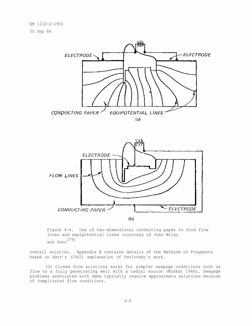
EM 1110-2-1901
30 Sep 86
Figure 4-4. Use of two-dimensional conducting paper to find flowlines and equipotential lines (courtesy of John Wiley
and Sons279)
overall solution. Appendix B contains details of the Methods of Fragmentsbased on Harr's (1962) explanation of Pavlovsky's work.
(3) Closed form solutions exist for simpler seepage conditions such asflow to a fully penetrating well with a radial source (Muskat 1946). Seepageproblems associated with dams typically require approximate solutions becauseof complicated flow conditions.
4-8
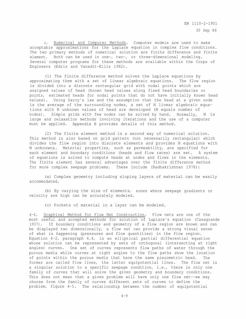
c. Numerical and Computer Methods.acceptable approximations for the Laplace
EM 1110-2-1901
30 Sep 86
Computer models are used to makeequation in complex flow conditions.
The two primary methods of numerical solution are finite difference and finiteelement. Both can be used in one-, two-, or three-dimensional modeling.Several computer programs for these methods are available within the Corps ofEngineers (Edris and Vanadit-Ellis 1982).
(1) The finite difference method solves the Laplace equations byapproximating them with a set of linear algebraic equations. The flow regionis divided into a discrete rectangular grid with nodal points which areassigned values of head (known head values along fixed head boundaries orpoints, estimated heads for nodal points that do not have initially known headvalues). Using Darcy's law and the assumption that the head at a given nodeis the average of the surrounding nodes, a set of N linear algebraic equa-tions with N unknown values of head are developed (N equals number ofnodes). Simple grids with few nodes can be solved by hand. Normally, N islarge and relaxation methods involving iterations and the use of a computermust be applied. Appendix B provides details of this method.
(2) The finite element method is a second way of numerical solution.This method is also based on grid pattern (not necessarily rectangular) whichdivides the flow region into discrete elements and provides N equations withN unknowns. Material properties, such as permeability, are specified foreach element and boundary conditions (heads and flow rates) are set. A systemof equations is solved to compute heads at nodes and flows in the elements.The finite element has several advantages over the finite difference methodfor more complex seepage problems. These include (Radhakrishnan 1978):
(a) Complex geometry including sloping layers of material can be easilyaccommodated.
(b) By varying the size of elements, zones where seepage gradients orvelocity are high can be accurately modeled.
(c) Pockets of material in a layer can be modeled.
4-6. Graphical Method for Flow Net Construction. Flow nets are one of themost useful and accepted methods for solution of Laplace's equation (Casagrande1937). If boundary conditions and geometry of a flow region are known and canbe displayed two dimensionally, a flow net can provide a strong visual senseof what is happening (pressures and flow quantities) in the flow region.Equation 4-2, paragraph 4.4, is an elliptical partial differential equationwhose solution can be represented by sets of orthogonal (intersecting at rightangles) curves. One set of curves represents flow paths of water through theporous media while curves at right angles to the flow paths show the locationof points within the porous media that have the same piezometric head. Theformer are called flow lines, the latter equipotential lines. The flow net isa singular solution to a specific seepage condition, i.e., there is only onefamily of curves that will solve the given geometry and boundary conditions.This does not mean that a given problem will have only one flow net--we maychoose from the family of curves different sets of curves to define theproblem, figure 4-5. The relationship between the number of equipotential
4-9
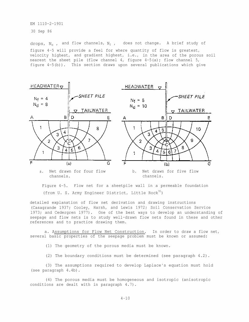
EM 1110-2-1901
30 Sep 86
drops, Nd , and flow channels, Nf , does not change. A brief study of
figure 4-5 will provide a feel for where quantity of flow is greatest,velocity highest, and gradient highest, i.e., in the area of the porous soilnearest the sheet pile (flow channel 4, figure 4-5(a); flow channel 5,figure 4-5(b)). This section draws upon several publications which give
a. Net drawn for four flowchannels.
b. Net drawn for five flowchannels.
Figure 4-5. Flow net for a sheetpile wall in a permeable foundation
(from U. S. Army Engineer District, Little Rock92)
detailed explanation of flow net derivation and drawing instructions(Casagrande 1937; Cooley, Harsh, and Lewis 1972; Soil Conservation Service1973; and Cedergren 1977). One of the best ways to develop an understanding ofseepage and flow nets is to study well-drawn flow nets found in these and otherreferences and to practice drawing them.
a. Assumptions for Flow Net Construction. In order to draw a flow net,several basic properties of the seepage problem must be known or assumed:
(1) The geometry of the porous media must be known.
(2) The boundary conditions must be determined (see paragraph 4.2).
(3) The assumptions required to develop Laplace's equation must hold(see paragraph 4.4b).
(4) The porous media must be homogeneous and isotropic (anisotropicconditions are dealt with in paragraph 4.7).
4-10
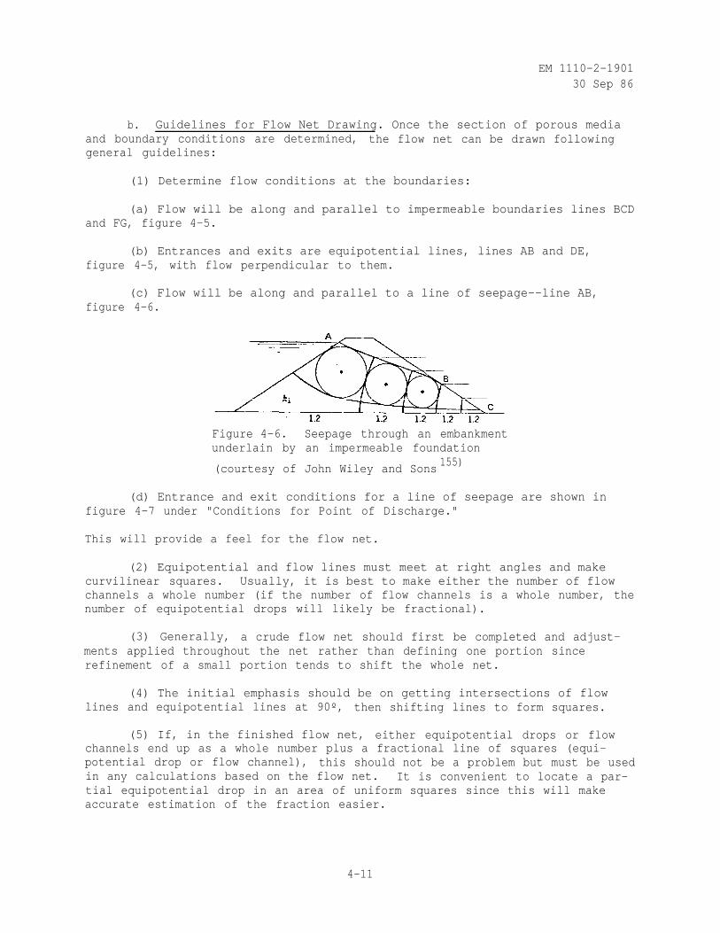
EM 1110-2-190130 Sep 86
b. Guidelines for Flow Net Drawing. Once the section of porous mediaand boundary conditions are determined, the flow net can be drawn followinggeneral guidelines:
(1) Determine flow conditions at the boundaries:
(a) Flow will be along and parallel to impermeable boundaries lines BCDand FG, figure 4-5.
(b) Entrances and exits are equipotential lines, lines AB and DE,figure 4-5, with flow perpendicular to them.
(c) Flow will be along and parallel to a line of seepage--line AB,figure 4-6.
Figure 4-6. Seepage through an embankmentunderlain by an impermeable foundation
(courtesy of John Wiley and Sons155)
(d) Entrance and exit conditions for a line of seepage are shown infigure 4-7 under "Conditions for Point of Discharge."
This will provide a feel for the flow net.
(2) Equipotential and flow lines must meet at right angles and makecurvilinear squares. Usually, it is best to make either the number of flowchannels a whole number (if the number of flow channels is a whole number, thenumber of equipotential drops will likely be fractional).
(3) Generally, a crude flow net should first be completed and adjust-ments applied throughout the net rather than defining one portion sincerefinement of a small portion tends to shift the whole net.
(4) The initial emphasis should be on getting intersections of flowlines and equipotential lines at 90º, then shifting lines to form squares.
(5) If, in the finished flow net, either equipotential drops or flowchannels end up as a whole number plus a fractional line of squares (equi-potential drop or flow channel), this should not be a problem but must be usedin any calculations based on the flow net. It is convenient to locate a par-tial equipotential drop in an area of uniform squares since this will makeaccurate estimation of the fraction easier.
4-11
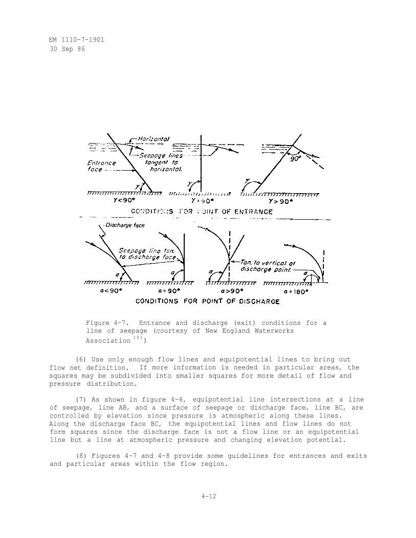
EM 1110-7-190130 Sep 86
Figure 4-7. Entrance and discharge (exit) conditions for aline of seepage (courtesy of New England Waterworks
Association 151)
(6) Use only enough flow lines and equipotential lines to bring outflow net definition. If more information is needed in particular areas, thesquares may be subdivided into smaller squares for more detail of flow andpressure distribution.
(7) As shown in figure 4-6, equipotential line intersections at a lineof seepage, line AB, and a surface of seepage or discharge face, line BC, arecontrolled by elevation since pressure is atmospheric along these lines.Along the discharge face BC, the equipotential lines and flow lines do notform squares since the discharge face is not a flow line or an equipotentialline but a line at atmospheric pressure and changing elevation potential.
(8) Figures 4-7 and 4-8 provide some guidelines for entrances and exitsand particular areas within the flow region.
4-12
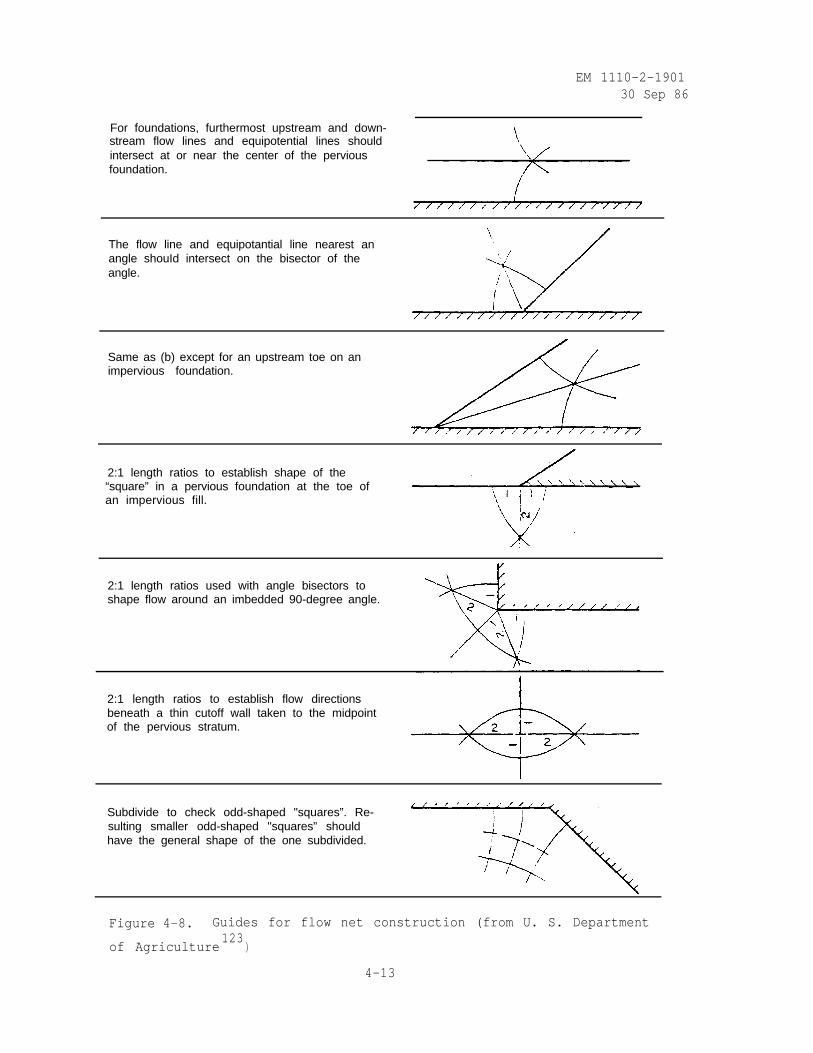
EM 1110-2-190130 Sep 86
For foundations, furthermost upstream and down-stream flow lines and equipotential lines shouldintersect at or near the center of the perviousfoundation.
The flow line and equipotantial line nearest anangle shouId intersect on the bisector of theangle.
Same as (b) except for an upstream toe on animpervious foundation.
2:1 length ratios to establish shape of the“square” in a pervious foundation at the toe ofan impervious fill.
2:1 length ratios used with angle bisectors toshape flow around an imbedded 90-degree angle.
2:1 length ratios to establish flow directionsbeneath a thin cutoff wall taken to the midpointof the pervious stratum.
Subdivide to check odd-shaped "squares”. Re-sulting smaller odd-shaped "squares” shouldhave the general shape of the one subdivided.
Figure 4-8. Guides for flow net construction (from U. S. Department
of Agriculture123
)
4-13
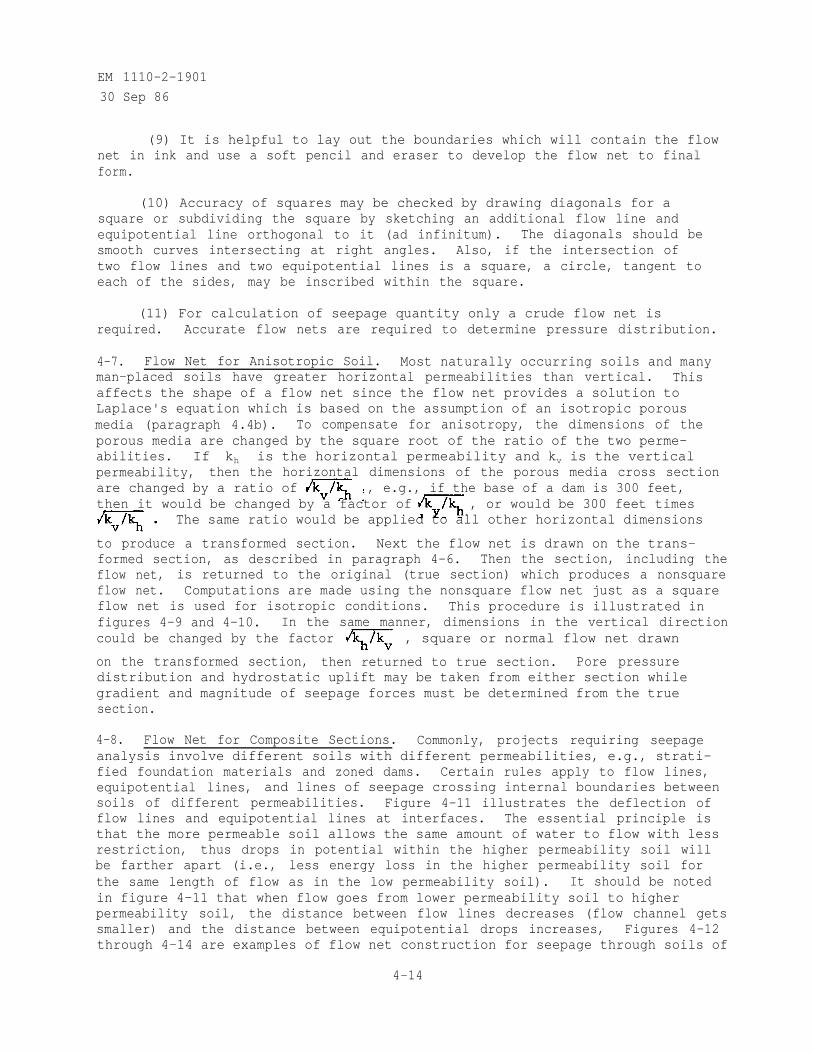
EM 1110-2-1901
30 Sep 86
(9) It is helpful to lay out the boundaries which will contain the flownet in ink and use a soft pencil and eraser to develop the flow net to finalform.
(10) Accuracy of squares may be checked by drawing diagonals for asquare or subdividing the square by sketching an additional flow line andequipotential line orthogonal to it (ad infinitum). The diagonals should besmooth curves intersecting at right angles. Also, if the intersection oftwo flow lines and two equipotential lines is a square, a circle, tangent toeach of the sides, may be inscribed within the square.
(11) For calculation of seepage quantity only a crude flow net isrequired. Accurate flow nets are required to determine pressure distribution.
4-7. Flow Net for Anisotropic Soil. Most naturally occurring soils and manyman-placed soils have greater horizontal permeabilities than vertical. Thisaffects the shape of a flow net since the flow net provides a solution toLaplace's equation which is based on the assumption of an isotropic porousmedia (paragraph 4.4b). To compensate for anisotropy, the dimensions of theporous media are changed by the square root of the ratio of the two perme-abilities. If khpermeability,
is the horizontal permeability and kv is the verticalthen the horizontal dimensions of the porous media cross section
are changed by a ratio of , e.g., if the base of a dam is 300 feet,then it would be changed by a factor of , or would be 300 feet times
The same ratio would be applied to all other horizontal dimensions
to produce a transformed section. Next the flow net is drawn on the trans-formed section, as described in paragraph 4-6. Then the section, including theflow net, is returned to the original (true section) which produces a nonsquareflow net. Computations are made using the nonsquare flow net just as a squareflow net is used for isotropic conditions. This procedure is illustrated infigures 4-9 and 4-10. In the same manner, dimensions in the vertical directioncould be changed by the factor , square or normal flow net drawn
on the transformed section, then returned to true section. Pore pressuredistribution and hydrostatic uplift may be taken from either section whilegradient and magnitude of seepage forces must be determined from the truesection.
4-8. Flow Net for Composite Sections. Commonly, projects requiring seepageanalysis involve different soils with different permeabilities, e.g., strati-fied foundation materials and zoned dams. Certain rules apply to flow lines,equipotential lines, and lines of seepage crossing internal boundaries betweensoils of different permeabilities. Figure 4-11 illustrates the deflection offlow lines and equipotential lines at interfaces. The essential principle isthat the more permeable soil allows the same amount of water to flow with lessrestriction, thus drops in potential within the higher permeability soil willbe farther apart (i.e., less energy loss in the higher permeability soil forthe same length of flow as in the low permeability soil). It should be notedin figure 4-11 that when flow goes from lower permeability soil to higherpermeability soil, the distance between flow lines decreases (flow channel getssmaller) and the distance between equipotential drops increases, Figures 4-12through 4-14 are examples of flow net construction for seepage through soils of
4-14
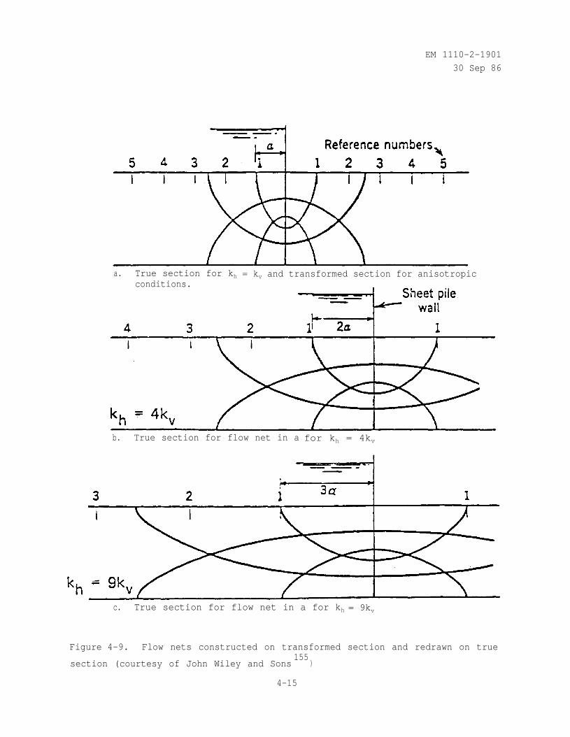
EM 1110-2-1901
30 Sep 86
a. True section for khconditions.
= kv and transformed section for anisotropic
b. True section for flow net in a for kh = 4kv
c. True section for flow net in a for kh = 9kv
Figure 4-9. Flow nets constructed on transformed section and redrawn on true
section (courtesy of John Wiley and Sons155
)
4-15
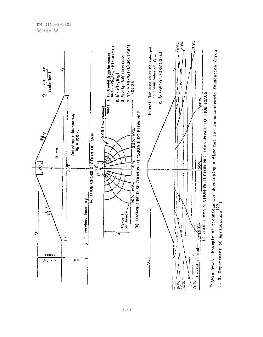
EM 1110-2-1901
30 Sep 86
4-16
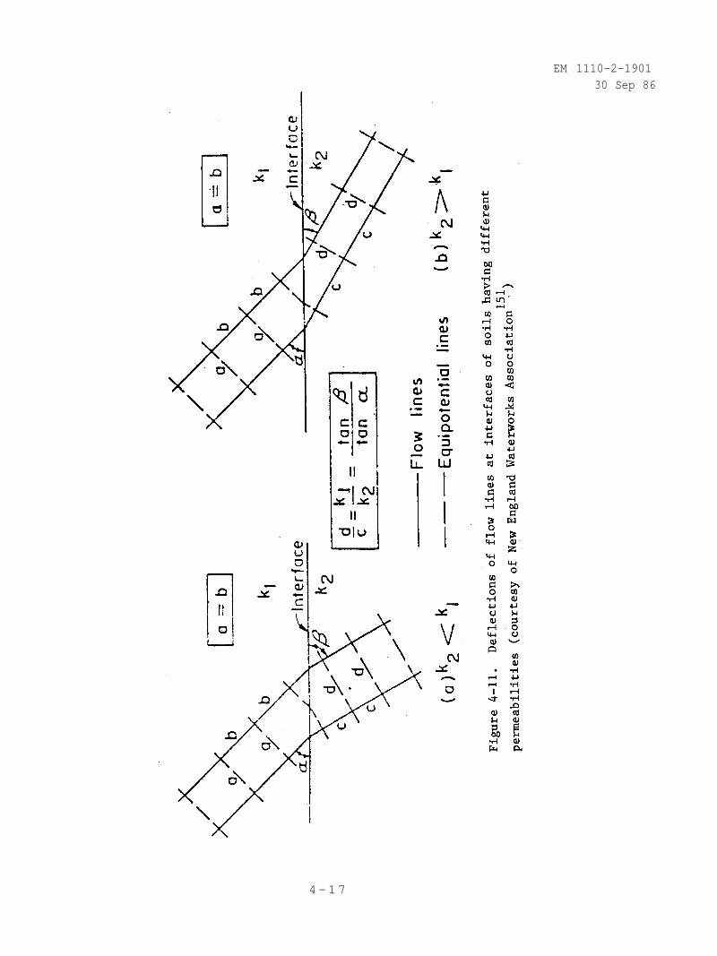
EM 1110-2-190130 Sep 86
4-17
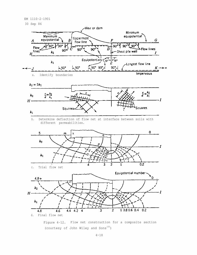
EM 1110-2-1901
30 Sep 86
a. Identify boundaries
b. Determine deflection of flow net at interface between soils withdifferent permeabilities.
flowc. Trial net
d. Final flow net
Figure 4-12. Flow net construction for a composite section
(courtesy of John Wiley and Sons155)
4-18
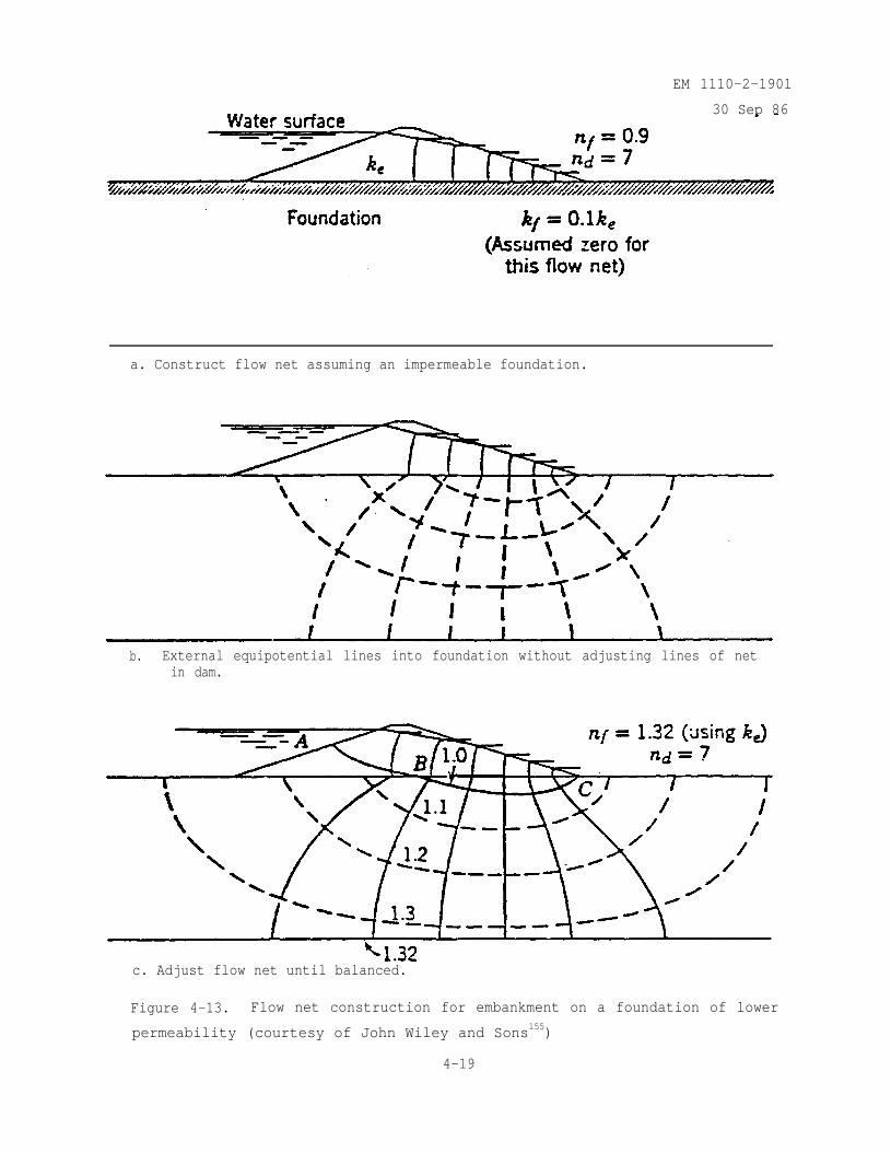
EM 1110-2-1901
30 Sep 86
a. Construct flow net assuming an impermeable foundation.
b. External equipotential lines into foundation without adjusting lines of netin dam.
c. Adjust flow net until balanced.
Figure 4-13. Flow net construction for embankment on a foundation of lower
permeability (courtesy of John Wiley and Sons155)
4-19
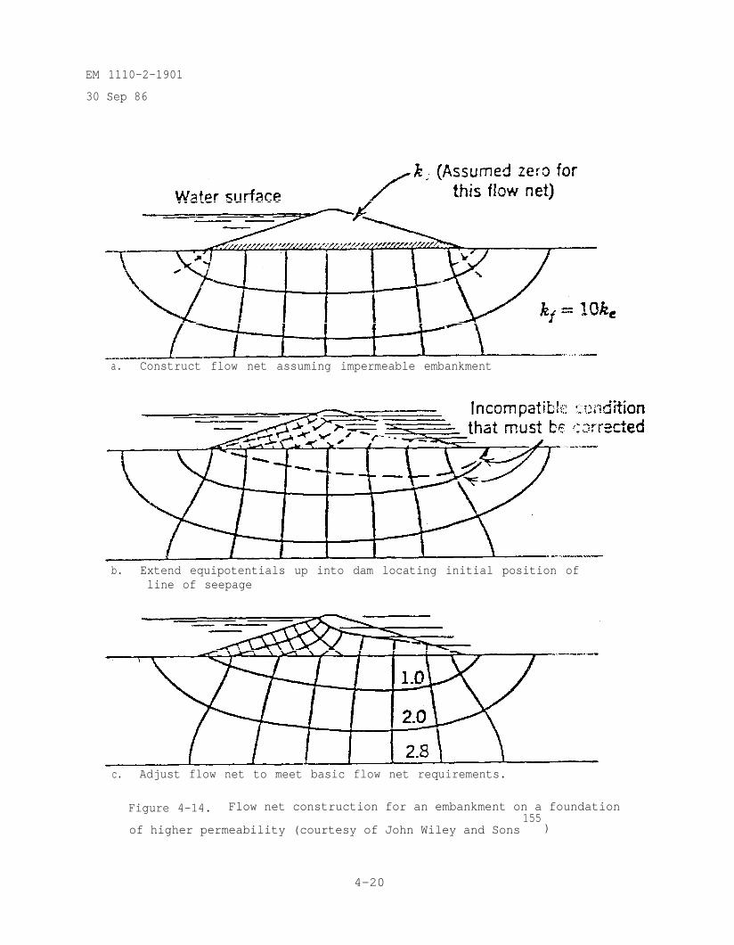
EM 1110-2-1901
30 Sep 86
a. Construct flow net assuming impermeable embankment
b. Extend equipotentials up into dam locating initial position ofline of seepage
c. Adjust flow net to meet basic flow net requirements.
Figure 4-14. Flow net construction for an embankment on a foundation
of higher permeability (courtesy of John Wiley and Sons155
)
4-20
EM 1110-2-1901
30 Sep 86
differing permeabilities. In all cases, flow lines and equipotential linesmaintain continuity across the interface between the soils though directionwill change abruptly. Additionally, the number of flow channels must remainconstant throughout the flow net. For the two examples of embankments withfoundations of differing permeabilities, figures 4-13 and 4-14, the flow ismore or less parallel to the interface, and the more permeable zone willdominate flow location and quantity. Because of this, the flow net can bestarted by assuming all flow goes through the most permeable zone. Once thisflow net is drawn, it is extended into the lower permeability zone and refinedto meet the general flow net criteria of paragraph 4.6. Transferring a line ofseepage across the interface of soils of differing permeability, such as in azoned dam, is more involved than transferring of flow lines and equipotentiallines and will be described in Chapter 6.
4-9. Determination of Seepage Quantities, Escape Gradients, Seepage Forces,and Uplift Pressures. A flow net is a picture of seepage conditions undergiven geometry and boundary conditions. It explains how pressures are dis-tributed and where flow is being directed. Coupled with the knowledge of headimposed on and the permeability of the porous media, the flow net can supplyimportant information about stability and flow quantity in two-dimensionalidealization of the real situation.
a. Seepage Quantities. Each of the complete flow channels passes anequal volume of water per unit of time, while partial channels carry a propor-tional flow. Each of the complete potential drops between equipotential linesis an equal portion of the total head, h , applied across the flow net withpartial drops having a proportionally smaller part. The number of flow chan-nels, including any partial channel, is given the symbol Nf while the number
of equipotential drops, including any partial drops, is given the symbol Nd .
The ratio of Nf/Nd is called the shape factor, , which is a characteristic
of the given geometry and boundary conditions and permeability ratios (k1/k2,
kv/kh). Quantity of flow per unit length through the porous media can be
determined by using Darcy's law, q = kiA and the shape factor. Total flow is
the sum of the flows through each flow channel, i.e., q = where q
is the total flow and is the flow through each complete flow channel. In
figure 4-10, q = Since is the head loss between each
equipotential line (h = is the dimension of a flow net square:
and from the Darcy equation:
4-21
EM 1110-2-1901
30 Sep 86
where a is the area of the rectangle perpendicular to the flow direction.If one side of the rectangle is one unit of length perpendicular of the planeof the flow net, and the other dimension is , thus a = Thisleads to:
Then:
which gives the quantity of seepage flow for each unit of thickness of porousmedia perpendicular to the plane of the flow net. Figure 4-10(b) gives anexample of this calculation for anisotropic seepage conditions in a damfoundation. The permeability, k' , used for anisotropic conditions,k' = is derived by Casagrande (1937).
b. Escape and Critical Gradients. The escape or exit gradient, ie ,is the rate of dissipation of head per unit of length in the area whereseepage is exiting the porous media. For confined flow, the area of concern isusually along the uppermost flow line near the flow exit, e.g., at thedownstream edge of a concrete or other impermeable structure, figure 4-15.Escape gradients for flow through embankments may also be studied by choosingsquares from the area of interest in the flow net (usually at or near the exitface and downstream toe) and calculating gradients. If the gradient is toogreat where seepage is exiting, soil particles may be removed from this area.This phenomenon, called flotation, can cause piping (the removal of soilparticles by moving water) which can lead to undermining and loss of thestructure. The gradient at which flotation of particles begins is termed thecritical gradient, icr . Critical gradient is determined by the in-place
4-22
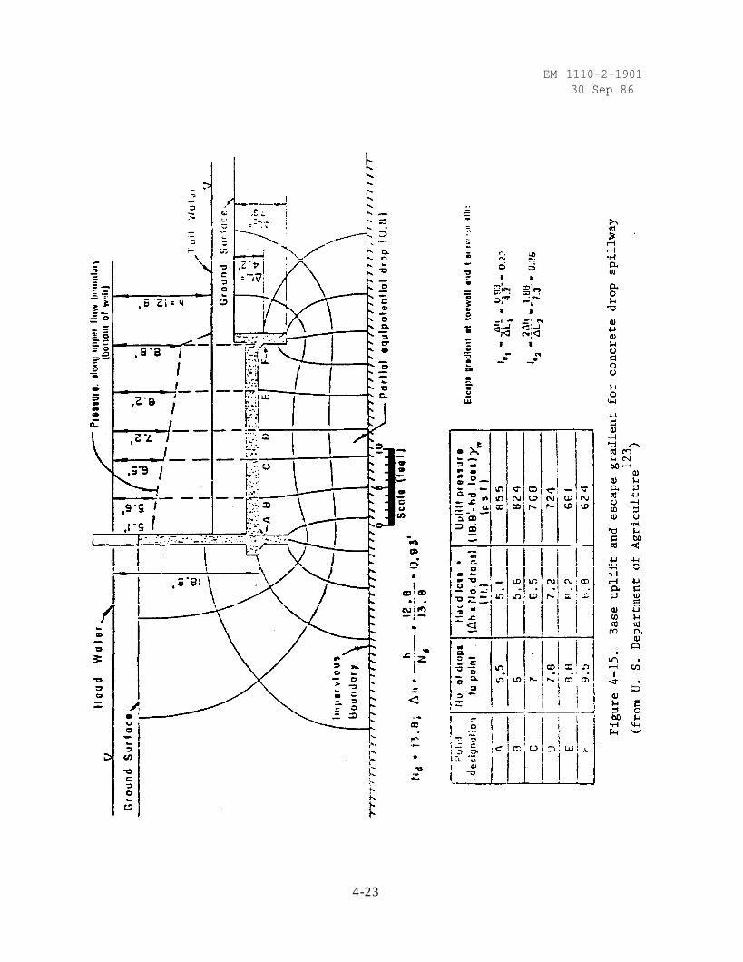
EM 1110-2-190130 Sep 86
4-23
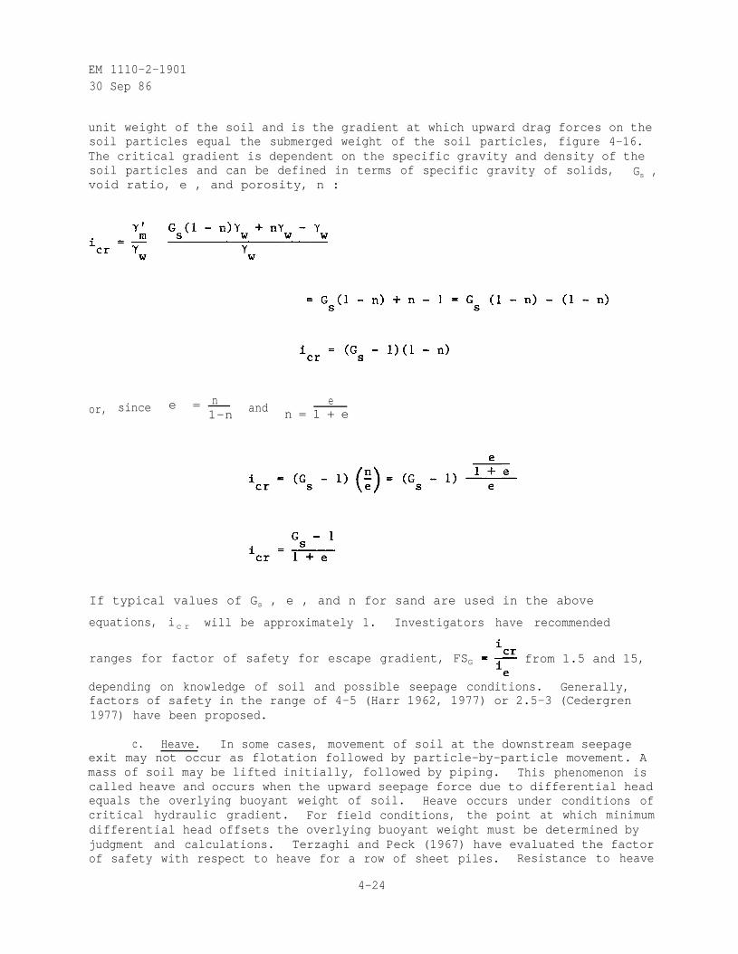
EM 1110-2-190130 Sep 86
unit weight of the soil and is the gradient at which upward drag forces on thesoil particles equal the submerged weight of the soil particles, figure 4-16.The critical gradient is dependent on the specific gravity and density of thesoil particles and can be defined in terms of specific gravity of solids, Gs ,void ratio, e , and porosity, n :
sincen
ande
or, e = 1-n n = 1 + e
If typical values of Gs , e , and n for sand are used in the above
equations, ic r will be approximately 1. Investigators have recommended
ranges for factor of safety for escape gradient, FSG from 1.5 and 15,
depending on knowledge of soil and possible seepage conditions. Generally,factors of safety in the range of 4-5 (Harr 1962, 1977) or 2.5-3 (Cedergren1977) have been proposed.
c. Heave. In some cases, movement of soil at the downstream seepageexit may not occur as flotation followed by particle-by-particle movement. Amass of soil may be lifted initially, followed by piping. This phenomenon iscalled heave and occurs when the upward seepage force due to differential headequals the overlying buoyant weight of soil. Heave occurs under conditions ofcritical hydraulic gradient. For field conditions, the point at which minimumdifferential head offsets the overlying buoyant weight must be determined byjudgment and calculations. Terzaghi and Peck (1967) have evaluated the factorof safety with respect to heave for a row of sheet piles. Resistance to heave
4-24
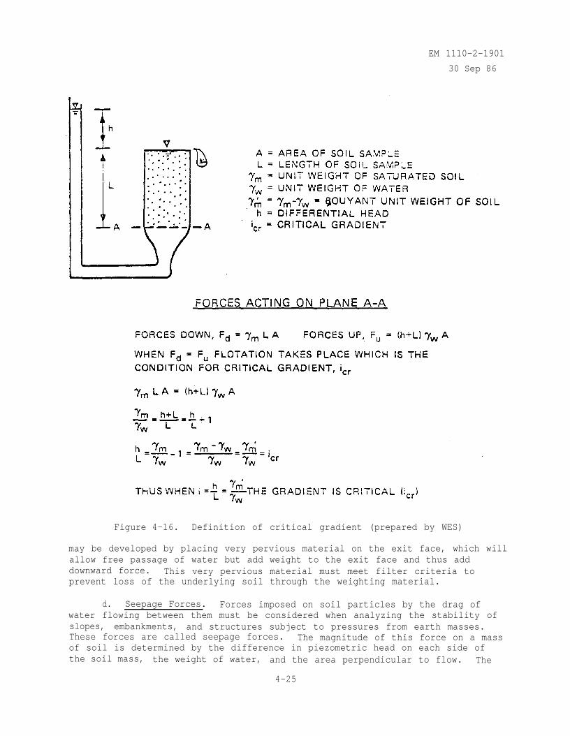
EM 1110-2-1901
30 Sep 86
Figure 4-16. Definition of critical gradient (prepared by WES)
may be developed by placing very pervious material on the exit face, which willallow free passage of water but add weight to the exit face and thus adddownward force. This very pervious material must meet filter criteria toprevent loss of the underlying soil through the weighting material.
d. Seepage Forces. Forces imposed on soil particles by the drag ofwater flowing between them must be considered when analyzing the stability ofslopes, embankments, and structures subject to pressures from earth masses.These forces are called seepage forces. The magnitude of this force on a massof soil is determined by the difference in piezometric head on each side ofthe soil mass, the weight of water, and the area perpendicular to flow. The
4-25
EM 1110-2-1901
30 Sep 86
seepage force acts in the same direction as flow, i.e. along flow lines. Con-sider the seepage force on plane A-A in figure 4-16. Since flow is verticallyupward, the direction of seepage force is up, the difference in piezometrichead is h , and the area perpendicular to flow is A . The seepage force,Fs , is the part of the upward forces due to differential head, h , or:
In terms of gradient and unit volume;
and using fS
as seepage force per unit volume:
Two methods of applying this force to use in stability analysis are describedby Cedergren (1977) and termed the gradient method and boundary pressuremethod. EM 1110-2-1902 gives examples of embankment stability analysesconsidering seepage forces. Additionally, the effect of buoyant forces on soilmass stability must also be considered. The upward or buoyant force, Fb ,causing reduction in effective stress on plane A-A, figure 4-15, is theremainder of the upward forces on plane A-A:
e. Uplift Pressures. When seepage occurs beneath concrete or otherimpermeable structures or strata, the underside of this impermeable barrier issubject to a force which tends to lift the structure upward. The determina-tion of this pressure or force is important in analyzing the stability of thestructure. An example of the analysis is given in figure 4-15. Summing ofthe uplift pressures over the bottom area of the spillway will give the totaluplift force on the structure for a stability analysis. Harr's text (1962)provides methods other than flow net construction to determine upliftpressures.
4-26
EM 1110-2-190130 Sep 86
CHAPTER 5CONFINED FLOW PROBLEMS
5-1. General Considerations. As explained in Chapter 4, confined flow existswhen the saturated pervious soil mass does not have a line of seepage boundary.Impervious weirs or gravity dams on pervious soil or rock are typical projectswhich have confined flow conditions. This chapter will consider two of thesecases. While examples of this chapter use flow nets, other methods for deter-mining uplift and gradient such as the Method of Fragments may be used.
5-2. Gravity Dam on Pervious Foundation of Finite Depth. Figure 5-1, a copyof figure 4-15, provides an example of an impervious structure on a perviousfoundation of finite depth with calculation of uplift and escape gradient.Figure 4-12 illustrates a gravity dam on a composite pervious foundation offinite depth and figure 4-10 shows an example of an impervious dam (though nota gravity dam) on a finite anisotropic foundation. A cross section of aclassical gravity dam/weir, figure 5-2 indicates the effect of a partiallypenetrating cutoff placed beneath the upstream portion of the dam. Comparingfigure 4-10(b) with figures 5-1 and 5-2 will show the reduction in gradient atthe downstream toe caused by embedment of the structure in the perviousfoundation. Embedment provides a longer upper flow line for a given structurewidth and reduces the gradient at the downstream toe of the structure. Othermeasures to reduce uplift and/or high gradients at the downstream toe includecutoffs beneath the downstream portion of the dam and placement of drainsbeneath the downstream portion of the dam.
5-3. Gravity Dam on Infinitely Deep Pervious Foundations. This case, illus-trated by figure 5-3, is symmetrical (if there are no asymmetrical cutoffs ordrains beneath the dam) and at large distances becomes a series of half circlearcs for flow lines and radial lines for equipotential lines. Since the up-stream (entrance) and downstream (exit) boundaries extend to infinity and thefoundation depth is infinite , the flow quantity is infinite. Obviously theanalyst must decide the limits of the problem and calculate flow quantitybased on those limits. The same manipulations and effects of embedment, cut-off, and drain described for the previous case will apply to this case.
5-1
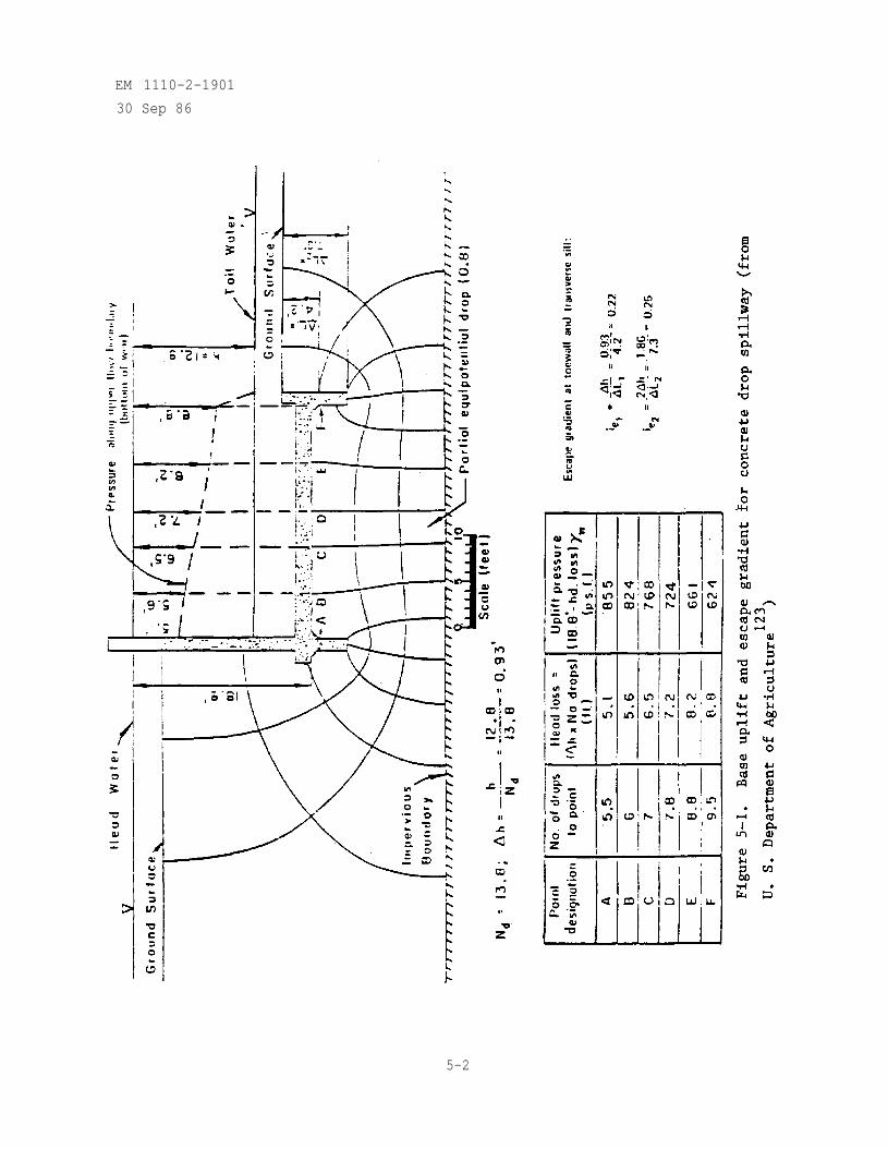
EM 1110-2-1901
30 Sep 86
5-2
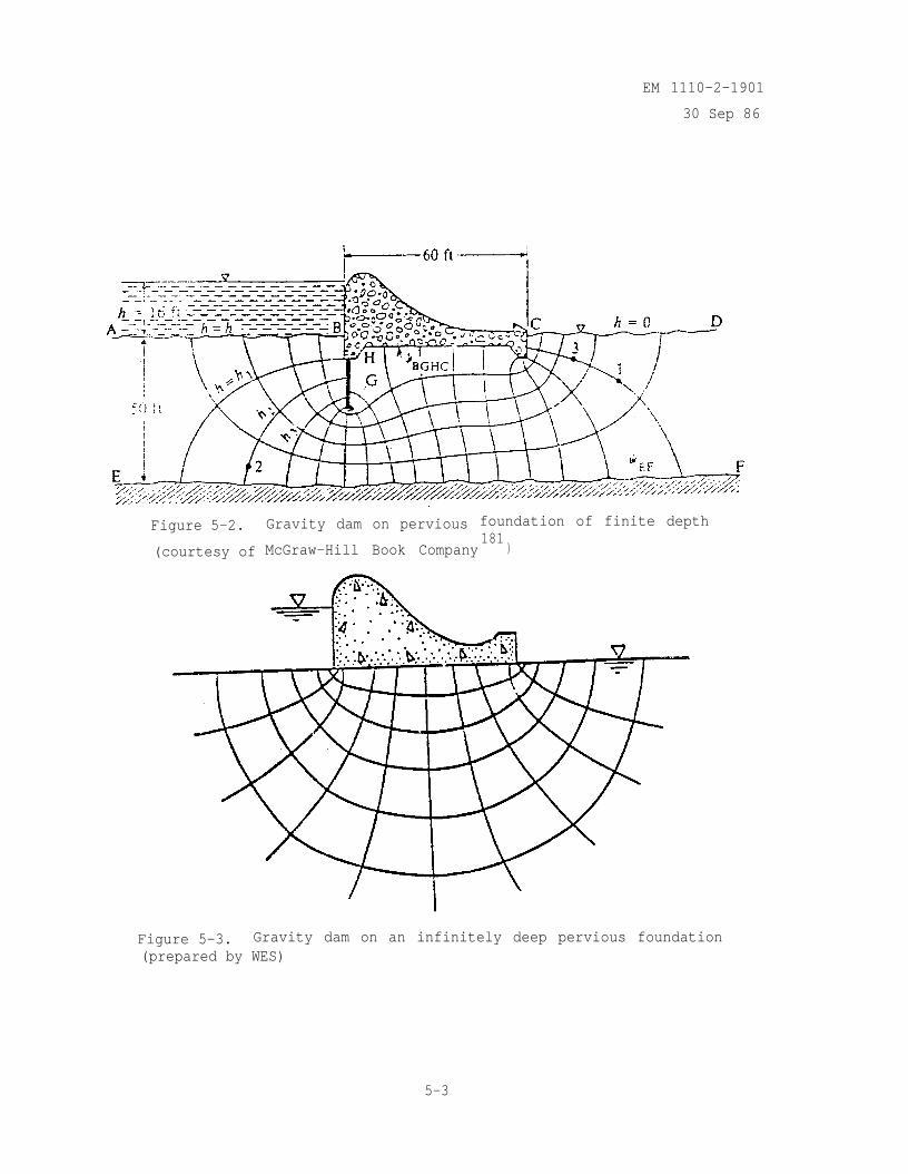
EM 1110-2-1901
30 Sep 86
Figure 5-2.
(courtesy of
Gravity dam on pervious foundation of finite depth
McGraw-Hill Book Company181
)
Figure 5-3. Gravity dam on an infinitely deep pervious foundation(prepared by WES)
5-3
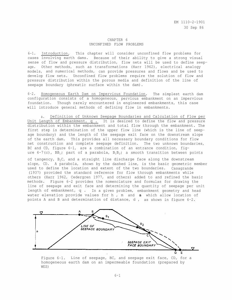
EM 1110-2-1901
30 Sep 86
CHAPTER 6UNCONFINED FLOW PROBLEMS
6-1. Introduction. This chapter will consider unconfined flow problems forcases involving earth dams. Because of their ability to give a strong visualsense of flow and pressure distribution, flow nets will be used to define seep-age. Other methods, such as transformations (Harr 1962), electrical analogymodels, and numerical methods, can provide pressures and flows and be used todevelop flow nets. Unconfined flow problems require the solution of flow andpressure distribution within the porous media and definition of the line ofseepage boundary (phreatic surface within the dam).
6-2. Homogeneous Earth Dam on Impervious Foundation. The simplest earth damconfiguration consists of a homogeneous, pervious embankment on an imperviousfoundation. Though rarely encountered in engineered embankments, this casewill introduce general methods of defining flow in embankments.
a. Definition of Unknown Seepage Boundaries and Calculation of Flow perUnit Length of Embankment, q . It is desired to define the flow and pressuredistribution within the embankment and total flow through the embankment. Thefirst step is determination of the upper flow line (which is the line of seep-age boundary) and the length of the seepage exit face on the downstream slopeof the earth dam. This provides all necessary boundary conditions for flownet construction and complete seepage definition. The two unknown boundaries,BC and CD, figure 6-1, are a combination of an entrance condition, fig-ure 4-7(c), BBl; part of a parabola, B1B2; a smooth transition between points
of tangency, B2C, and a straight line discharge face along the downstreamslope, CD. A parabola, shown by the dashed line, is the basic geometric memberused to define the location and extent of the two boundaries. Casagrande(1937) provided the standard reference for flow through embankments whileothers (Harr 1962, Cedergren 1977, and others) added to and refined the basicmethods. Figure 6-2 provides the nomenclature and formulas for drawing theline of seepage and exit face and determining the quantity of seepage per unitlength of embankment, q . In a given problem, embankment geometry and headwater elevation provide values for h , m and which allow location ofpoints A and B and determination of distance, d , as shown in figure 6-2.
Figure 6-1. Line of seepage, BC, and seepage exit face, CD, for ahomogeneous earth dam on an impermeable foundation (prepared byWES)
6-1
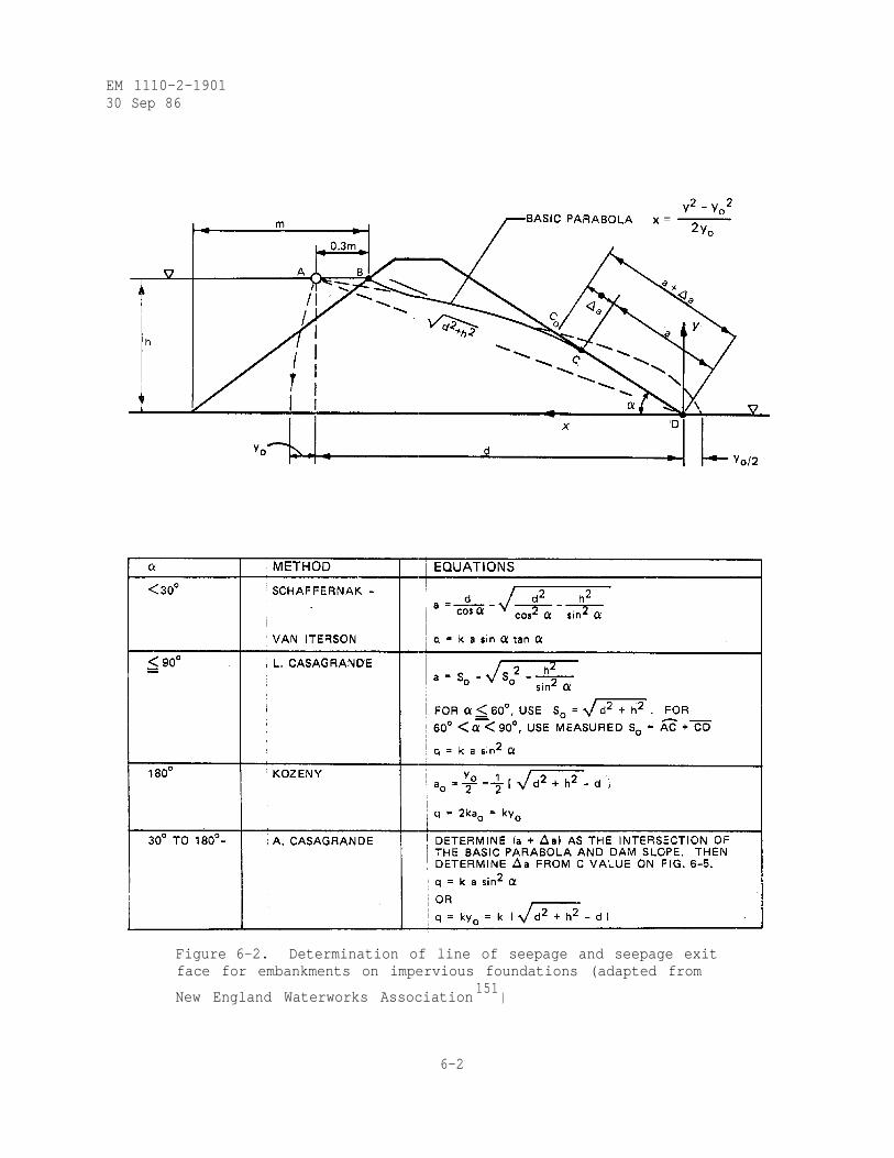
EM 1110-2-190130 Sep 86
Figure 6-2. Determination of line of seepage and seepage exitface for embankments on impervious foundations (adapted from
New England Waterworks Association151
)
6-2
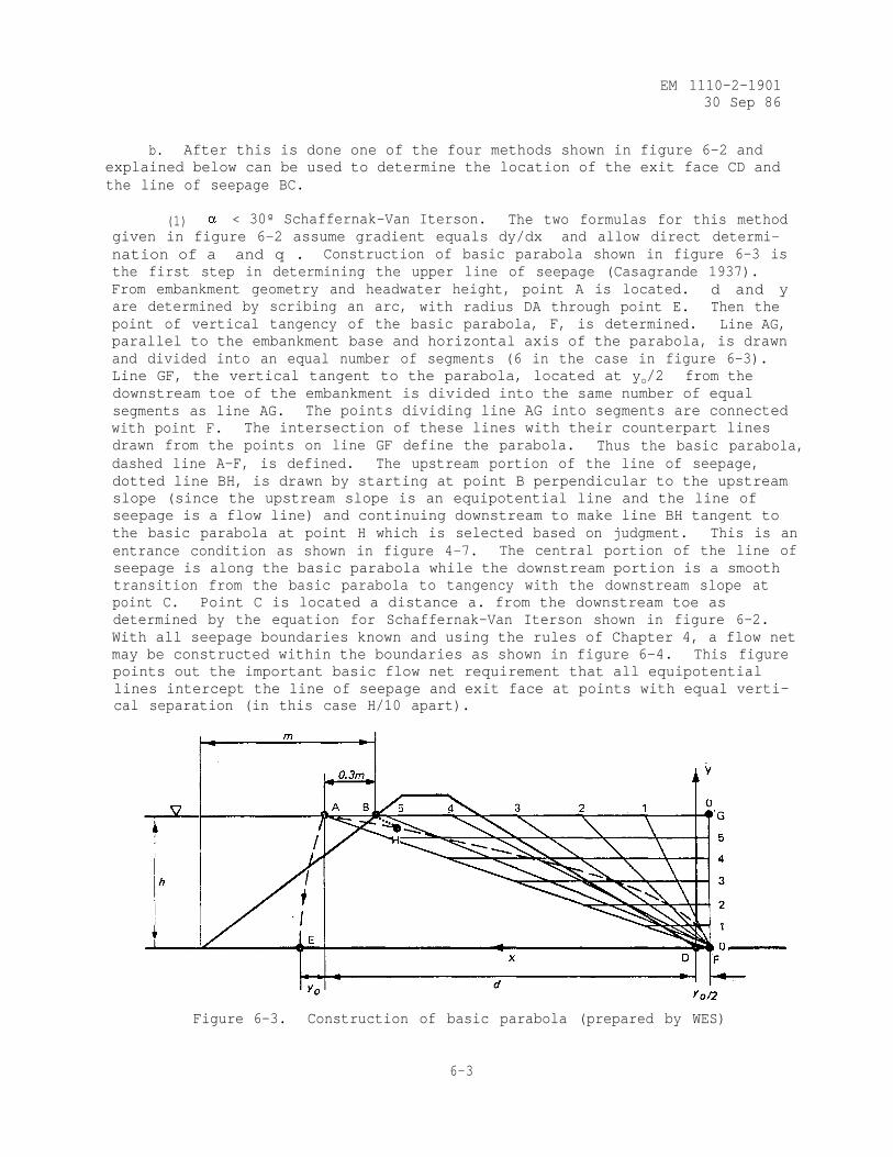
EM 1110-2-190130 Sep 86
b. After this is done one of the four methods shown in figure 6-2 andexplained below can be used to determine the location of the exit face CD andthe line of seepage BC.
(1) < 30º Schaffernak-Van Iterson. The two formulas for this methodgiven in figure 6-2 assume gradient equals dy/dx and allow direct determi-nation of a and q . Construction of basic parabola shown in figure 6-3 isthe first step in determining the upper line of seepage (Casagrande 1937).From embankment geometry and headwater height, point A is located. d and yare determined by scribing an arc, with radius DA through point E. Then thepoint of vertical tangency of the basic parabola, F, is determined. Line AG,parallel to the embankment base and horizontal axis of the parabola, is drawnand divided into an equal number of segments (6 in the case in figure 6-3).Line GF, the vertical tangent to the parabola, located at yo/2 from thedownstream toe of the embankment is divided into the same number of equalsegments as line AG. The points dividing line AG into segments are connectedwith point F. The intersection of these lines with their counterpart linesdrawn from the points on line GF define the parabola. Thus the basic parabola,dashed line A-F, is defined. The upstream portion of the line of seepage,dotted line BH, is drawn by starting at point B perpendicular to the upstreamslope (since the upstream slope is an equipotential line and the line of seepage is a flow line) and continuing downstream to make line BH tangent tothe basic parabola at point H which is selected based on judgment. This is anentrance condition as shown in figure 4-7. The central portion of the line ofseepage is along the basic parabola while the downstream portion is a smoothtransition from the basic parabola to tangency with the downstream slope atpoint C. Point C is located a distance a. from the downstream toe asdetermined by the equation for Schaffernak-Van Iterson shown in figure 6-2.With all seepage boundaries known and using the rules of Chapter 4, a flow netmay be constructed within the boundaries as shown in figure 6-4. This figurepoints out the important basic flow net requirement that all equipotentiallines intercept the line of seepage and exit face at points with equal verti-cal separation (in this case H/10 apart).
Figure 6-3. Construction of basic parabola (prepared by WES)
6-3
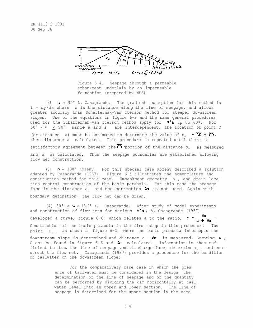
EM 1110-2-190130 Sep 86
Figure 6-4. Seepage through a permeableembankment underlain by an impermeablefoundation (prepared by WES)
(2) < 90° L. Casagrande. The gradient assumption for this method isi = dy/ds where s is the distance along the line of seepage, and allowsgreater accuracy than Schaffernak-Van Iterson method for steeper downstreamslopes. Use of the equations in figure 6-2 and the same general proceduresused for the Schaffernak-Van Iterson method apply for up to 60º. For60° < < 90°, since a and s are interdependent, the location of point C
(or distance a) must be estimated to determine the value of sothen distance a calculated. This procedure is repeated until there is
satisfactory agreement between the portion of the distance so as measured
and a as calculated. Thus the seepage boundaries are established allowingflow net construction.
(3) = 180° Kozeny. For this special case Kozeny described a solutionadapted by Casagrande (1937). Figure 6-5 illustrates the nomenclature andconstruction method for this case. Embankment geometry, h , and drain loca-tion control construction of the basic parabola. For this case the seepageface is the distance a0 and the correction is not used. Again with
boundary definition, the flow net can be drawn.
(4) 30° < < 18.0° A. Casagrande. After study of model experimentsand construction of flow nets for various , A. Casagrande (1937)
developed a curve, figure 6-6, which relates a to the ratio,
Construction of the basic parabola is the first step in this procedure. Thepoint, Co , as shown in figure 6-2, where the basic parabola intercepts the
downstream slope is determined and distance a + is measured. KnowingC can be found in figure 6-6 and calculated. Information is then suf-ficient to draw the line of seepage and discharge face, determine q , and con-struct the flow net. Casagrande (1937) provides a procedure for the conditionof tailwater on the downstream slope:
For the comparatively rare case in which the pres-ence of tailwater must be considered in the design, thedetermination of the line of seepage and of the quantitycan be performed by dividing the dam horizontally at tail-water level into an upper and lower section. The line ofseepage is determined for the upper section in the same
6-4
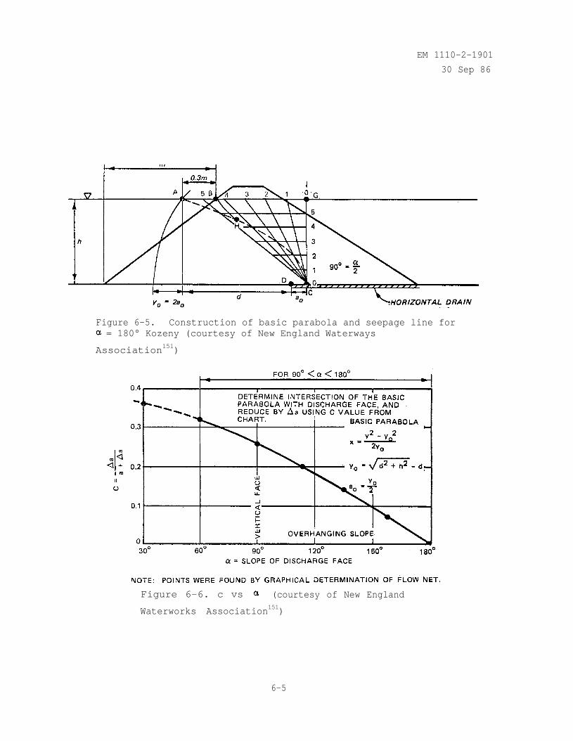
EM 1110-2-1901
30 Sep 86
Figure 6-5. Construction of basic parabola and seepage line for= 180° Kozeny (courtesy of New England Waterways
Association151)
Figure 6-6. c vs (courtesy of New England
Waterworks Association151)
6-5
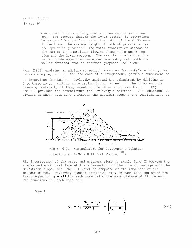
EM 1110-2-1901
30 Sep 86
manner as if the dividing line were an impervious bound-ary. The seepage through the lower section is determinedby means of Darcy's law, using the ratio of the differencein head over the average length of path of percolation asthe hydraulic gradient. The total quantity of seepage isthe sum of the quantities flowing through the upper sec-tion and the lower section. The results obtained by thisrather crude approximation agree remarkably well with thevalues obtained from an accurate graphical solution.
Harr (1962) explains an additional method, known as Pavlovsky's solution, fordetermining a0 and q for the case of a homogeneous, pervious embankment on
an impervious foundation. Pavlovsky analyzed the embankment by dividing itinto three zones, writing an equation for q in each of the zones and, byassuming continuity of flow, equating the three equations for q . Fig-ure 6-7 provides the nomenclature for Pavlovsky's solution. The embankment isdivided as shown with Zone I between the upstream slope and a vertical line at
Figure 6-7. Nomenclature for Pavlovsky's solution
(courtesy of McGraw-Hill Book Company180
)
the intersection of the crest and upstream slope (y axis), Zone II between they axis and a vertical line at the intersection of the line of seepage with thedownstream slope, and Zone III which is composed of the remainder of thedownstream toe. Pavlovsky assumed horizontal flow in each zone and wrote thebasic equation q for each zone using the nomenclature of figure 6-7.The equations for each zone are:
Zone I
(6-1)
6-6
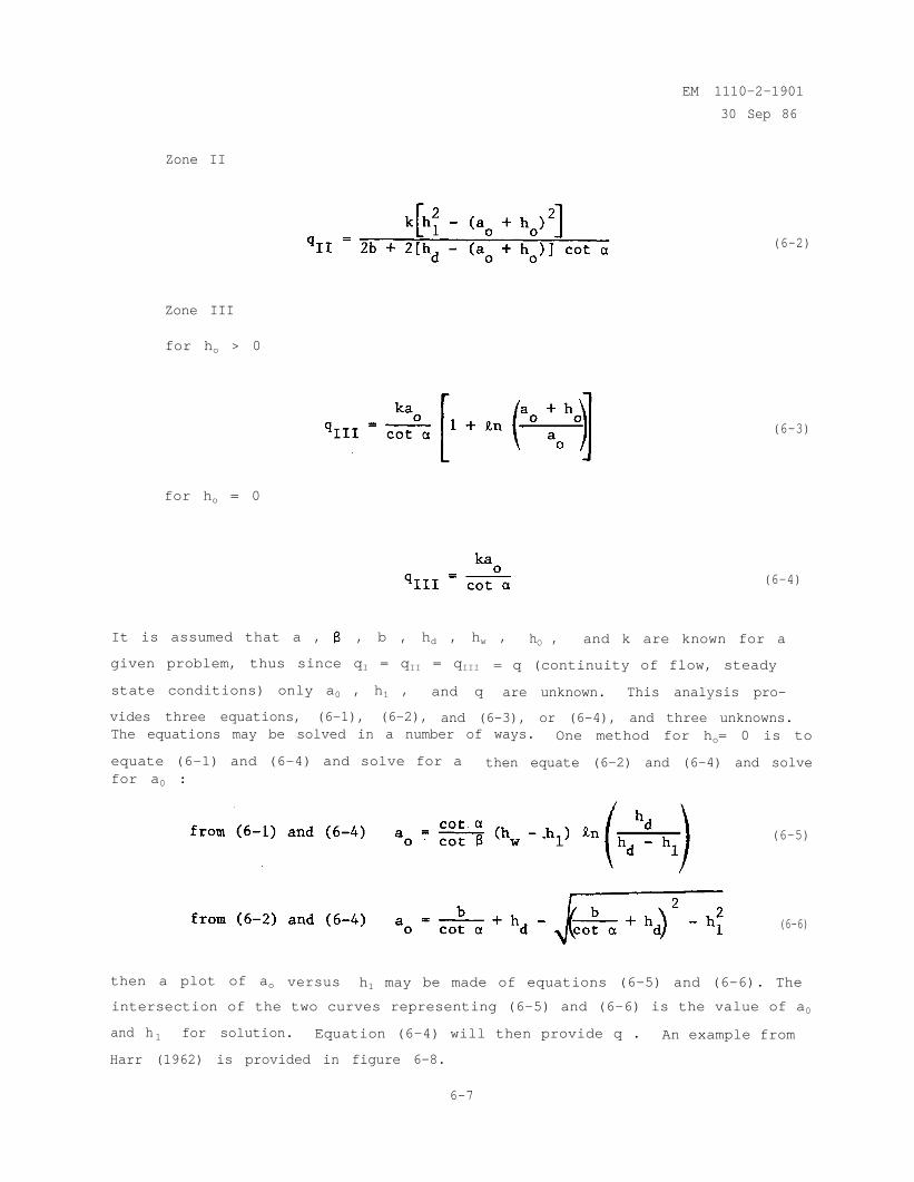
EM 1110-2-1901
30 Sep 86
Zone II
Zone III
for ho > 0
for ho = 0
(6-2)
(6-3)
(6-4)
It is assumed that a , , b , hd , hw , hO , and k are known for a
given problem, thus since qI = qII = qIII = q (continuity of flow, steady
state conditions) only a0 , h1 , and q are unknown. This analysis pro-
vides three equations, (6-1), (6-2), and (6-3), or (6-4), and three unknowns.The equations may be solved in a number of ways. One method for ho= 0 is to
equate (6-1) and (6-4) and solve for a then equate (6-2) and (6-4) and solvefor a0 :
(6-5)
(6-6)
then a plot of ao versus h1 may be made of equations (6-5) and (6-6). The
intersection of the two curves representing (6-5) and (6-6) is the value of a0
and h 1 for solution. Equation (6-4) will then provide q . An example from
Harr (1962) is provided in figure 6-8.
6-7
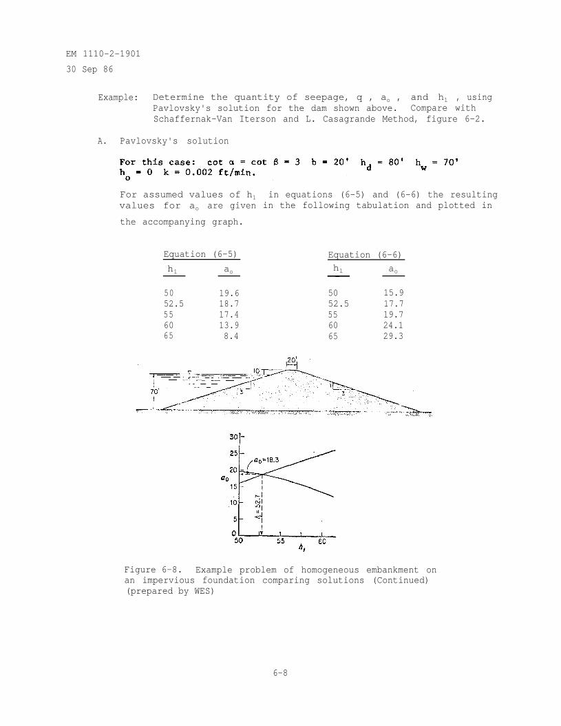
EM 1110-2-1901
30 Sep 86
Example: Determine the quantity of seepage, q , ao ,Pavlovsky's solution for the dam shown above.
and h1 , usingCompare with
Schaffernak-Van Iterson and L. Casagrande Method, figure 6-2.
A. Pavlovsky's solution
For assumed values of h1values for ao are given
the accompanying graph.
in equations (6-5) and (6-6) the resultingin the following tabulation and plotted in
Equation (6-5) Equation (6-6)
h1 ao hl ao
50 19.6 50 15.952.5 18.7 52.5 17.755 17.4 55 19.760 13.9 60 24.165 8.4 65 29.3
Figure 6-8. Example problem of homogeneous embankment onan impervious foundation comparing solutions (Continued)(prepared by WES)
6-8
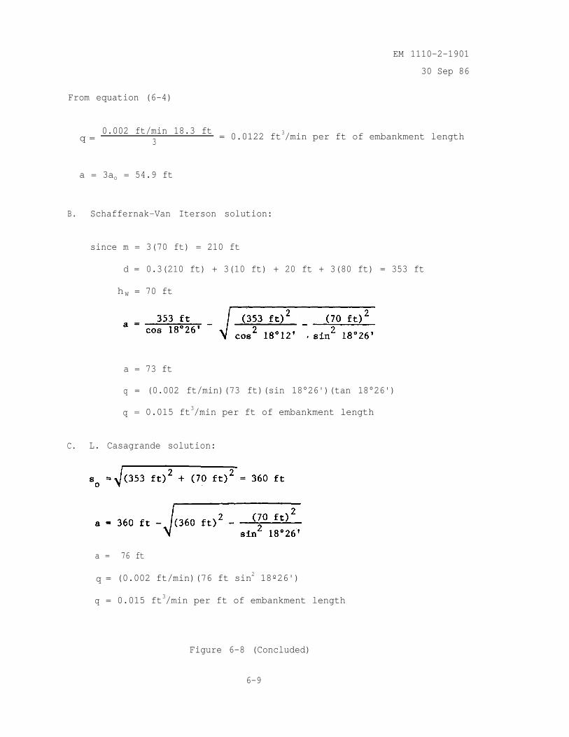
EM 1110-2-1901
30 Sep 86
From equation (6-4)
q =0.002 ft/min 18.3 ft
3= 0.0122 ft3/min per ft of embankment length
a = 3ao = 54.9 ft
B. Schaffernak-Van Iterson solution:
since m = 3(70 ft) = 210 ft
d = 0.3(210 ft) + 3(10 ft) + 20 ft + 3(80 ft) = 353 ft
h W = 70 ft
a = 73 ft
q = (0.002 ft/min)(73 ft)(sin 18°26')(tan 18°26')
q = 0.015 ft3/min per ft of embankment length
C. L. Casagrande solution:
a = 76 ft
q = (0.002 ft/min)(76 ft sin2 18º26')
q = 0.015 ft3/min per ft of embankment length
Figure 6-8 (Concluded)
6-9
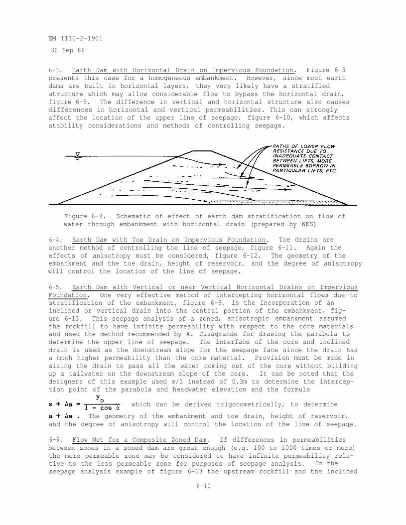
EM 1110-2-1901
30 Sep 86
6-3. Earth Dam with Horizontal Drain on Impervious Foundation. Figure 6-5presents this case for a homogeneous embankment. However, since most earthdams are built in horizontal layers, they very likely have a stratifiedstructure which may allow considerable flow to bypass the horizontal drain,figure 6-9. The difference in vertical and horizontal structure also causesdifferences in horizontal and vertical permeabilities. This can stronglyaffect the location of the upper line of seepage, figure 6-10, which affectsstability considerations and methods of controlling seepage.
Figure 6-9. Schematic of effect of earth dam stratification on flow ofwater through embankment with horizontal drain (prepared by WES)
6-4. Earth Dam with Toe Drain on Impervious Foundation. Toe drains areanother method of controlling the line of seepage, figure 6-11. Again theeffects of anisotropy must be considered, figure 6-12. The geometry of theembankment and the toe drain, height of reservoir, and the degree of anisotropywill control the location of the line of seepage.
6-5. Earth Dam with Vertical or near Vertical Horizontal Drains on ImperviousFoundation. One very effective method of intercepting horizontal flows due tostratification of the embankment, figure 6-9, is the incorporation of aninclined or vertical drain into the central portion of the embankment, fig-ure 6-13. This seepage analysis of a zoned, anisotropic embankment assumedthe rockfill to have infinite permeability with respect to the core materialsand used the method recommended by A. Casagrande for drawing the parabola todetermine the upper line of seepage. The interface of the core and inclineddrain is used as the downstream slope for the seepage face since the drain hasa much higher permeability than the core material. Provision must be made insizing the drain to pass all the water coming out of the core without buildingup a tailwater on the downstream slope of the core. It can be noted that thedesigners of this example used m/3 instead of 0.3m to determine the intercep-tion point of the parabola and headwater elevation and the formula
which can be derived trigonometrically, to determine
The geometry of the embankment and toe drain, height of reservoir,and the degree of anisotropy will control the location of the line of seepage.
6-6. Flow Net for a Composite Zoned Dam. If differences in permeabilitiesbetween zones in a zoned dam are great enough (e.g. 100 to 1000 times or more)the more permeable zone may be considered to have infinite permeability rela-tive to the less permeable zone for purposes of seepage analysis. In theseepage analysis example of figure 6-13 the upstream rockfill and the inclined
6-10
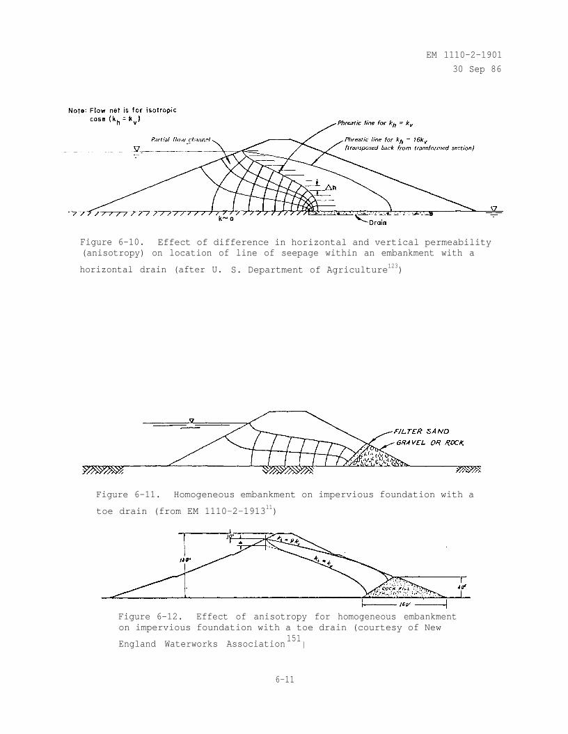
EM 1110-2-1901
30 Sep 86
Figure 6-10. Effect of difference in horizontal and vertical permeability(anisotropy) on location of line of seepage within an embankment with a
horizontal drain (after U. S. Department of Agriculture123)
Figure 6-11. Homogeneous embankment on impervious foundation with a
toe drain (from EM 1110-2-191311)
Figure 6-12. Effect of anisotropy for homogeneous embankmenton impervious foundation with a toe drain (courtesy of New
England Waterworks Association151
)
6-11
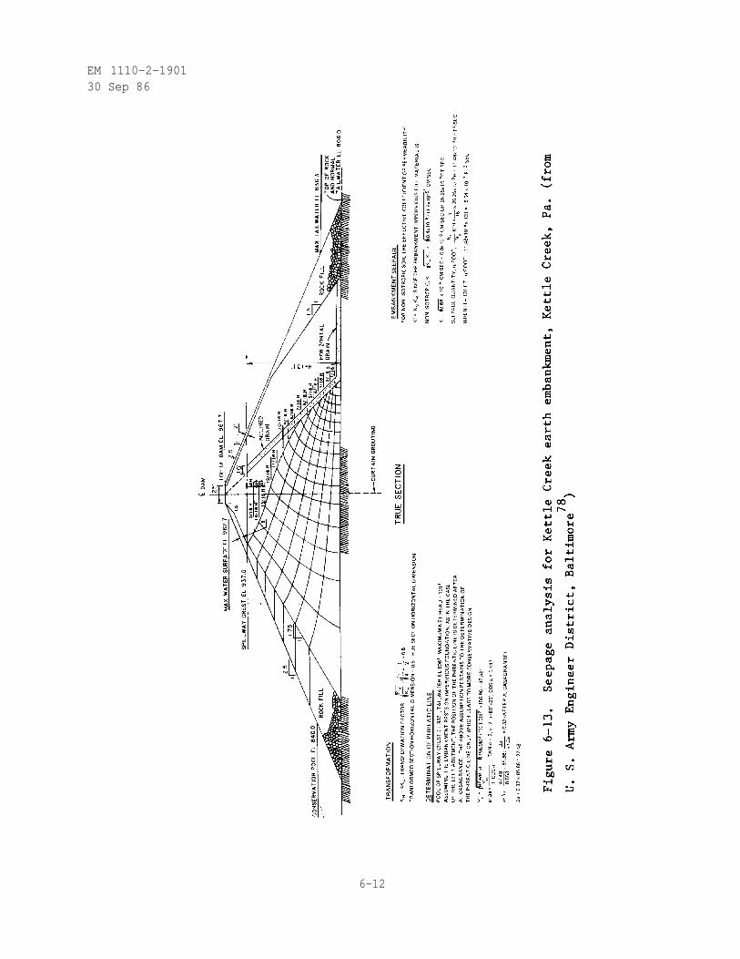
EM 1110-2-190130 Sep 86
6-12
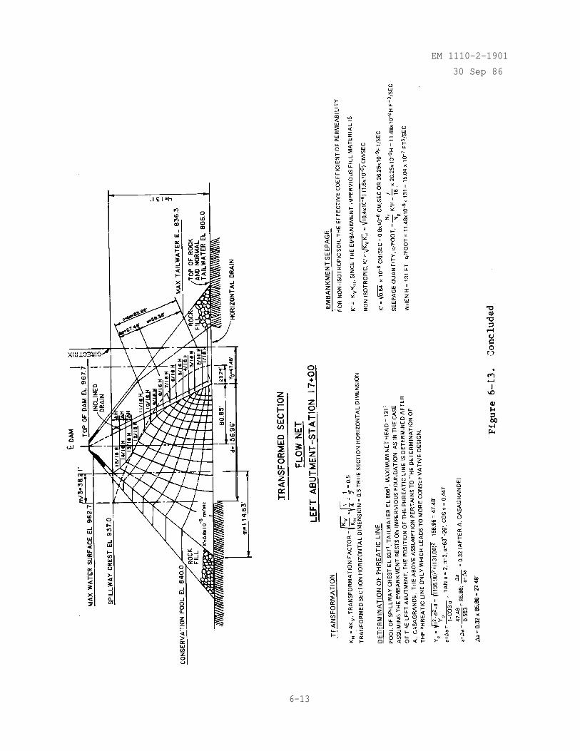
EM 1110-2-1901
30 Sep 86
6-13
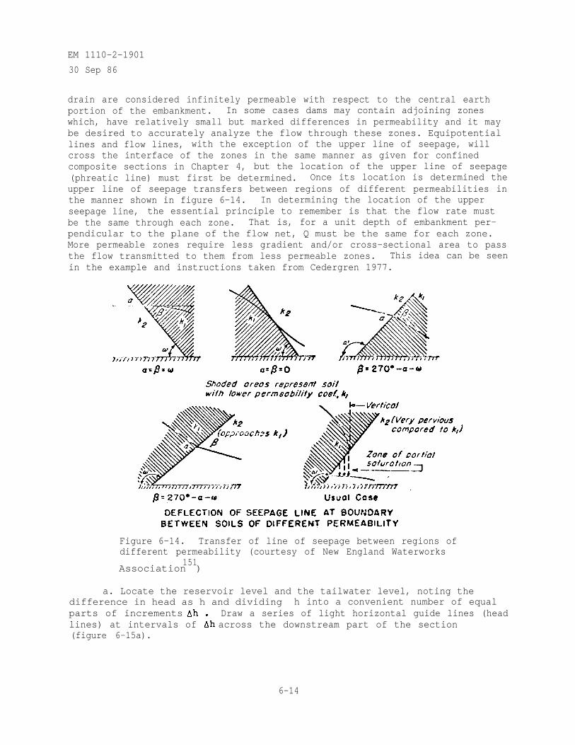
EM 1110-2-1901
30 Sep 86
drain are considered infinitely permeable with respect to the central earthportion of the embankment. In some cases dams may contain adjoining zoneswhich, have relatively small but marked differences in permeability and it maybe desired to accurately analyze the flow through these zones. Equipotentiallines and flow lines, with the exception of the upper line of seepage, willcross the interface of the zones in the same manner as given for confinedcomposite sections in Chapter 4, but the location of the upper line of seepage(phreatic line) must first be determined. Once its location is determined theupper line of seepage transfers between regions of different permeabilities inthe manner shown in figure 6-14. In determining the location of the upperseepage line, the essential principle to remember is that the flow rate mustbe the same through each zone. That is, for a unit depth of embankment per-pendicular to the plane of the flow net, Q must be the same for each zone.More permeable zones require less gradient and/or cross-sectional area to passthe flow transmitted to them from less permeable zones. This idea can be seenin the example and instructions taken from Cedergren 1977.
Figure 6-14. Transfer of line of seepage between regions ofdifferent permeability (courtesy of New England Waterworks
151Association )
a. Locate the reservoir level and the tailwater level, noting thedifference in head as h and dividing h into a convenient number of equalparts of increments Draw a series of light horizontal guide lines (headlines) at intervals of across the downstream part of the section(figure 6-15a).
6-14
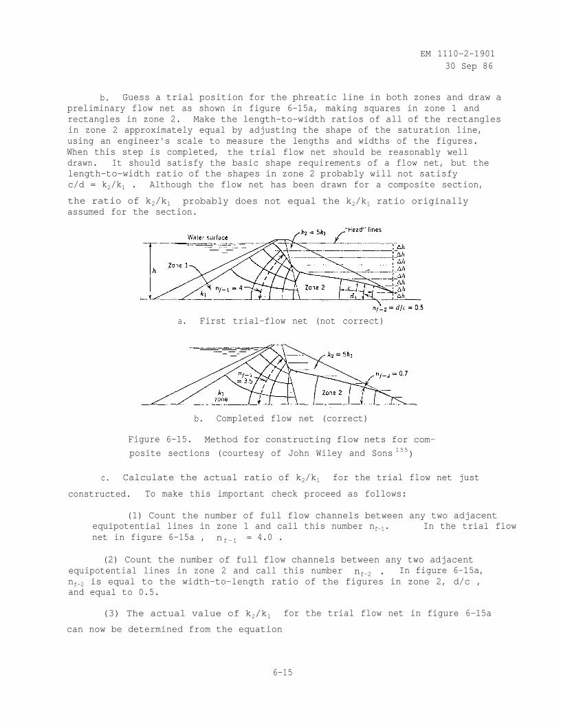
EM 1110-2-190130 Sep 86
b. Guess a trial position for the phreatic line in both zones and draw apreliminary flow net as shown in figure 6-15a, making squares in zone 1 andrectangles in zone 2. Make the length-to-width ratios of all of the rectanglesin zone 2 approximately equal by adjusting the shape of the saturation line,using an engineer's scale to measure the lengths and widths of the figures.When this step is completed, the trial flow net should be reasonably welldrawn. It should satisfy the basic shape requirements of a flow net, but thelength-to-width ratio of the shapes in zone 2 probably will not satisfyc/d = k2/k1 . Although the flow net has been drawn for a composite section,
the ratio of k2/k1 probably does not equal the k2/k1 ratio originallyassumed for the section.
a. First trial-flow net (not correct)
b. Completed flow net (correct)
Figure 6-15. Method for constructing flow nets for com-
posite sections (courtesy of John Wiley and Sons 155)
c. Calculate the actual ratio of k2/k1 for the trial flow net just
constructed. To make this important check proceed as follows:
(1) Count the number of full flow channels between any two adjacentequipotential lines in zone 1 and call this number nf-1. In the trial flownet in figure 6-15a , nf-1 = 4.0 .
(2) Count the number of full flow channels between any two adjacentequipotential lines in zone 2 and call this number nf-2 . In figure 6-15a,nf-2 is equal to the width-to-length ratio of the figures in zone 2, d/c ,and equal to 0.5.
(3) The actual value of k2/k1 for the trial flow net in figure 6-15a
can now be determined from the equation
6-15
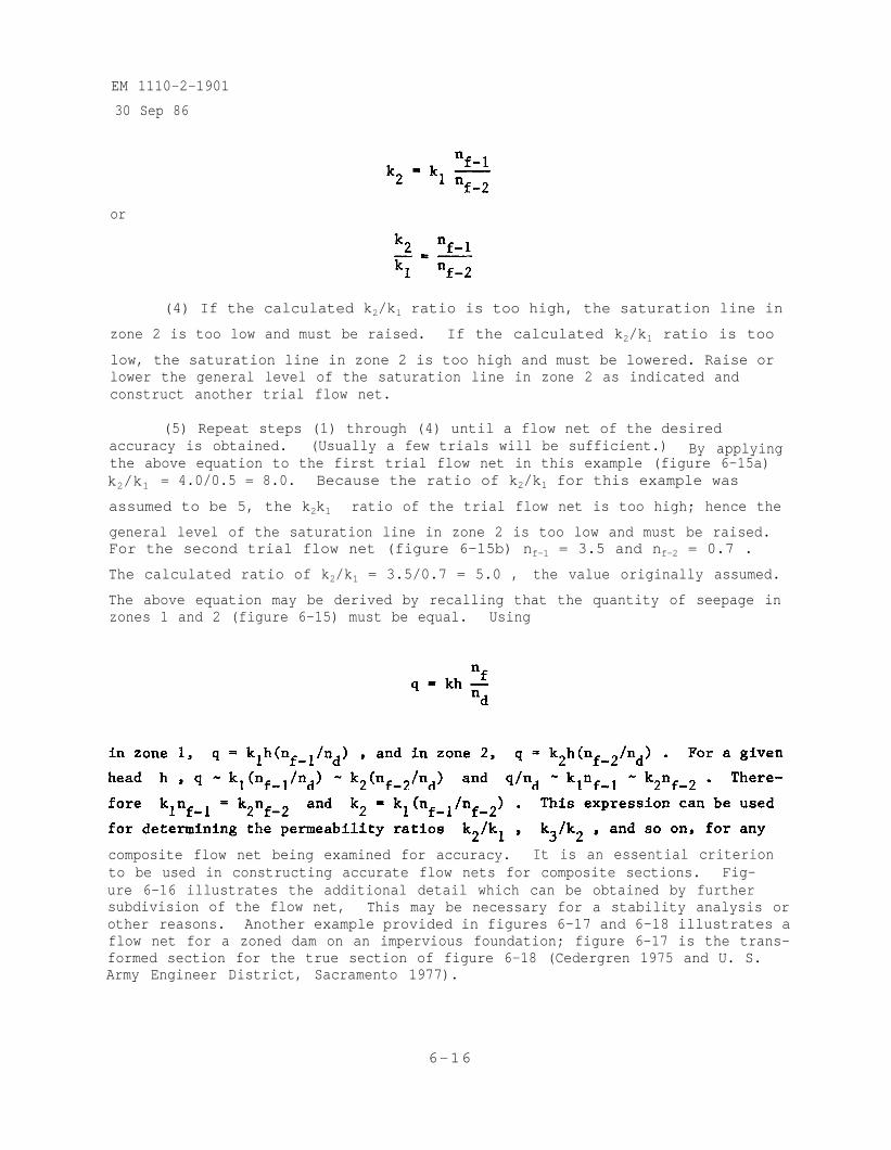
EM 1110-2-1901
30 Sep 86
or
(4) If the calculated k2/k1 ratio is too high, the saturation line in
zone 2 is too low and must be raised. If the calculated k2/k1 ratio is too
low, the saturation line in zone 2 is too high and must be lowered. Raise orlower the general level of the saturation line in zone 2 as indicated andconstruct another trial flow net.
(5) Repeat steps (1) through (4) until a flow net of the desiredaccuracy is obtained. (Usually a few trials will be sufficient.) By applyingthe above equation to the first trial flow net in this example (figure 6-15a)k2/k1 = 4.0/0.5 = 8.0. Because the ratio of k2/k1 for this example was
assumed to be 5, the k2k1 ratio of the trial flow net is too high; hence the
general level of the saturation line in zone 2 is too low and must be raised.For the second trial flow net (figure 6-15b) nf-1 = 3.5 and nf-2 = 0.7 .
The calculated ratio of k2/k1 = 3.5/0.7 = 5.0 , the value originally assumed.
The above equation may be derived by recalling that the quantity of seepage inzones 1 and 2 (figure 6-15) must be equal. Using
composite flow net being examined for accuracy. It is an essential criterionto be used in constructing accurate flow nets for composite sections. Fig-ure 6-16 illustrates the additional detail which can be obtained by furthersubdivision of the flow net, This may be necessary for a stability analysis orother reasons. Another example provided in figures 6-17 and 6-18 illustrates aflow net for a zoned dam on an impervious foundation; figure 6-17 is the trans-formed section for the true section of figure 6-18 (Cedergren 1975 and U. S.Army Engineer District, Sacramento 1977).
6-16
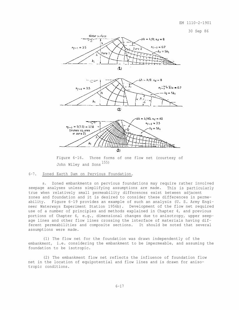
EM 1110-2-1901
30 Sep 86
Figure 6-16. Three forms of one flow net (courtesy of
John Wiley and Sons 155)
6-7. Zoned Earth Dam on Pervious Foundation.
a. Zoned embankments on pervious foundations may require rather involvedseepage analyses unless simplifying assumptions are made. This is particularlytrue when relatively small permeability differences exist between adjacentzones and foundation and it is desired to consider these differences in perme-ability. Figure 6-19 provides an example of such an analysis (U. S. Army Engi-neer Waterways Experiment Station 1956b). Development of the flow net requireduse of a number of principles and methods explained in Chapter 4, and previousportions of Chapter 6, e.g., dimensional changes due to anisotropy, upper seep-age lines and other flow lines crossing the interface of materials having dif-ferent permeabilities and composite sections. It should be noted that severalassumptions were made.
(1) The flow net for the foundation was drawn independently of theembankment, i.e. considering the embankment to be impermeable, and assuming thefoundation to be isotropic.
(2) The embankment flow net reflects the influence of foundation flownet in the location of equipotential and flow lines and is drawn for aniso-tropic conditions.
6-17
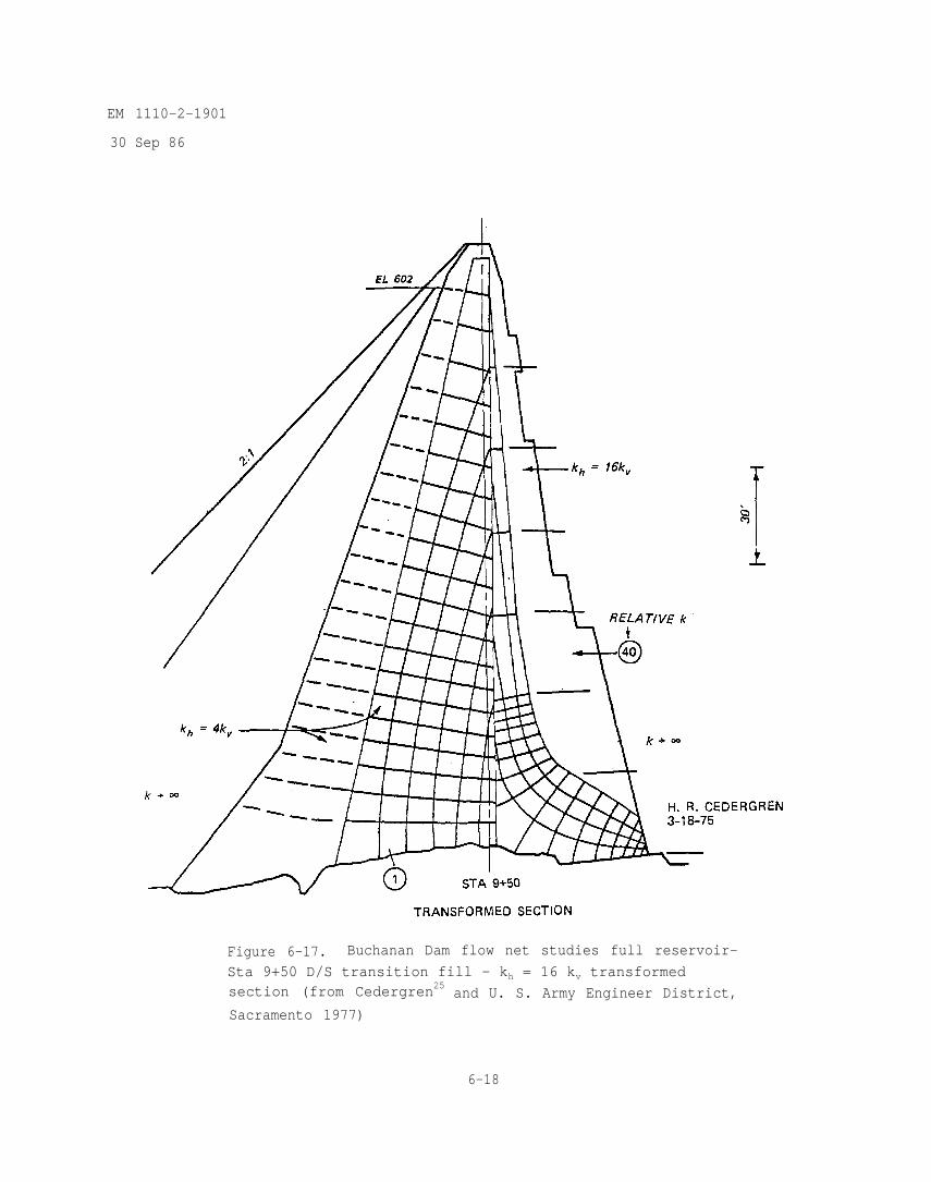
EM 1110-2-1901
30 Sep 86
Figure 6-17. Buchanan Dam flow net studies full reservoir-
Sta 9+50 D/S transition fill - kh = 16 kv transformedsection (from Cedergren25 and U. S. Army Engineer District,
Sacramento 1977)
6-18
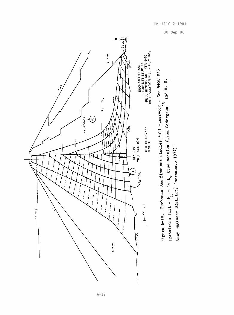
EM 1110-2-1901
30 Sep 86
6-19
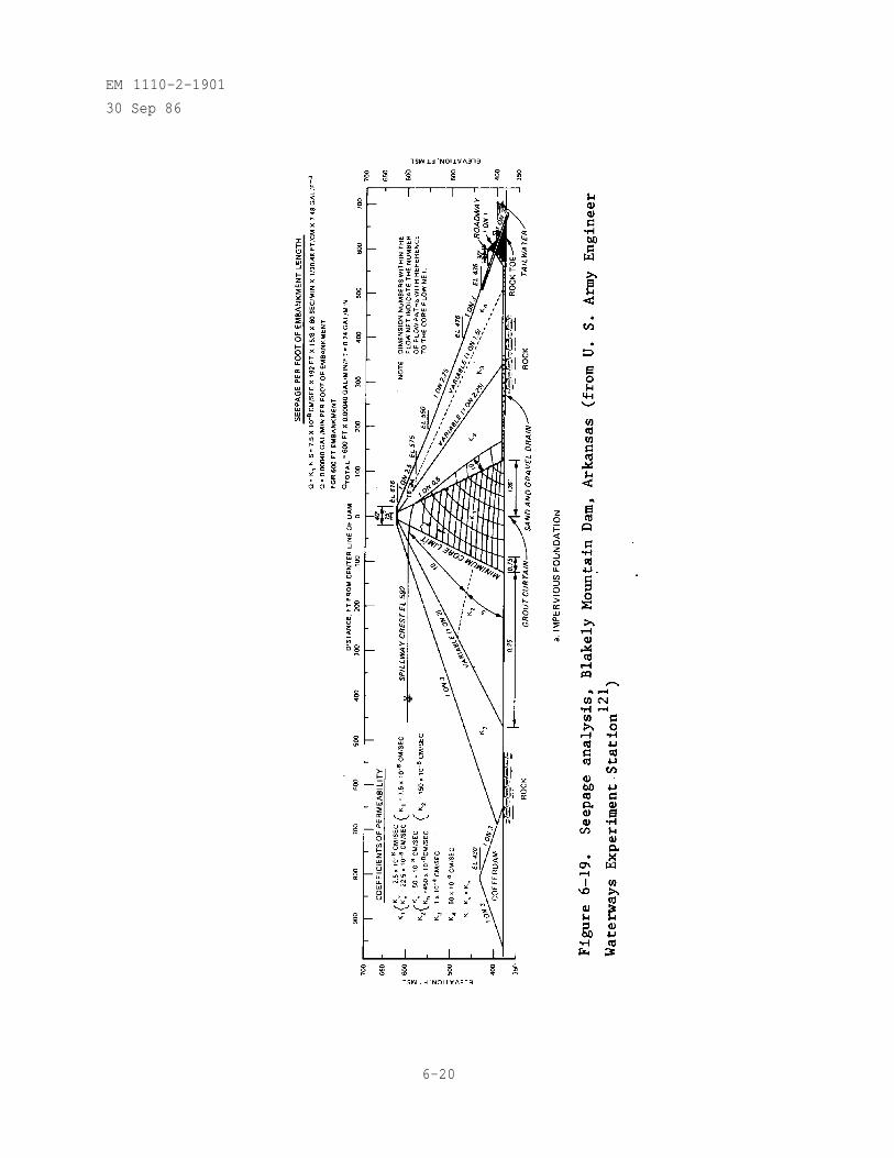
EM 1110-2-1901
30 Sep 86
6-20
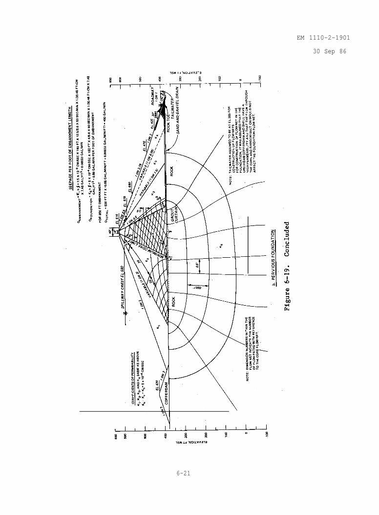
EM 1110-2-1901
30 Sep 86
6-21

EM 1110-2-1901
30 Sep 86
(3) The flow nets were constructed assuming a tailwater elevation of388 ft (approximate elevation of the base of the embankment) while seepagequantities calculations assumed a tailwater elevation of 400 ft as shown onthe cross sections (i.e., h for calculation of Q is 192 ft).
(4) For calculation of Q in figure 6-19(b) the flow nets were con-sidered to be separate but to have the same number of equipotential drops.
b. This example provides evidence that a large permeable member of theembankment-foundation material controls the quantity of flow. In this case therelatively impermeable embankment materials needed to be considered in order todetermine the upper seepage line, the extent of saturated materials, and theexpected pore pressures within the embankment. Seepage for this problem mightalso be evaluated using a finite element computer program.
6-22
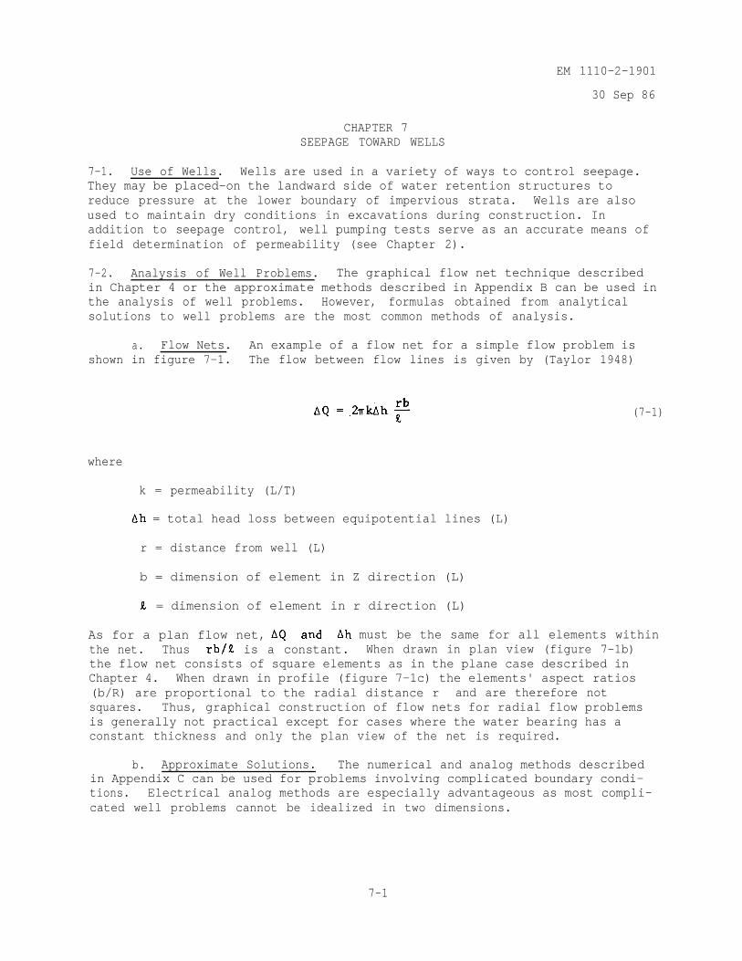
EM 1110-2-1901
30 Sep 86
CHAPTER 7SEEPAGE TOWARD WELLS
7-1. Use of Wells. Wells are used in a variety of ways to control seepage.They may be placed-on the landward side of water retention structures toreduce pressure at the lower boundary of impervious strata. Wells are alsoused to maintain dry conditions in excavations during construction. Inaddition to seepage control, well pumping tests serve as an accurate means offield determination of permeability (see Chapter 2).
7-2. Analysis of Well Problems. The graphical flow net technique describedin Chapter 4 or the approximate methods described in Appendix B can be used inthe analysis of well problems. However, formulas obtained from analyticalsolutions to well problems are the most common methods of analysis.
a. Flow Nets. An example of a flow net for a simple flow problem isshown in figure 7-1. The flow between flow lines is given by (Taylor 1948)
(7-1)
where
k = permeability (L/T)
= total head loss between equipotential lines (L)
r = distance from well (L)
b = dimension of element in Z direction (L)
= dimension of element in r direction (L)
As for a plan flow net, must be the same for all elements withinthe net. Thus is a constant. When drawn in plan view (figure 7-1b)the flow net consists of square elements as in the plane case described inChapter 4. When drawn in profile (figure 7-1c) the elements' aspect ratios(b/R) are proportional to the radial distance r and are therefore notsquares. Thus, graphical construction of flow nets for radial flow problemsis generally not practical except for cases where the water bearing has aconstant thickness and only the plan view of the net is required.
b. Approximate Solutions. The numerical and analog methods describedin Appendix C can be used for problems involving complicated boundary condi-tions. Electrical analog methods are especially advantageous as most compli-cated well problems cannot be idealized in two dimensions.
7-1
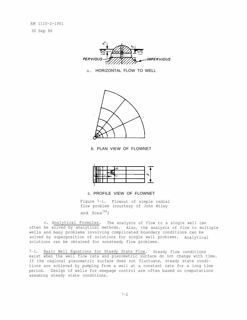
EM 1110-2-1901
30 Sep 86
a. HORIZONTAL FLOW TO WELL
b. PLAN VIEW OF FLOWNET
c. PROFILE VIEW OF FLOWNET
Figure 7-1. Flowout of simple radialflow problem (courtesy of John Wiley
and Sons268)
c. Analytical Formulas. The analysis of flow to a single well canoften be solved by analytical methods. Also, the analysis of flow to multiplewells and many problems involving complicated boundary conditions can besolved by superposition of solutions for single well problems. Analyticalsolutions can be obtained for nonsteady flow problems.
7-3. Basic Well Equations for Steady State Flow. Steady flow conditionsexist when the well flow rate and piezometric surface do not change with time.If the regional piezometric surface does not fluctuate, steady state condi-tions are achieved by pumping from a well at a constant rate for a long timeperiod. Design of wells for seepage control are often based on computationsassuming steady state conditions.
7-2
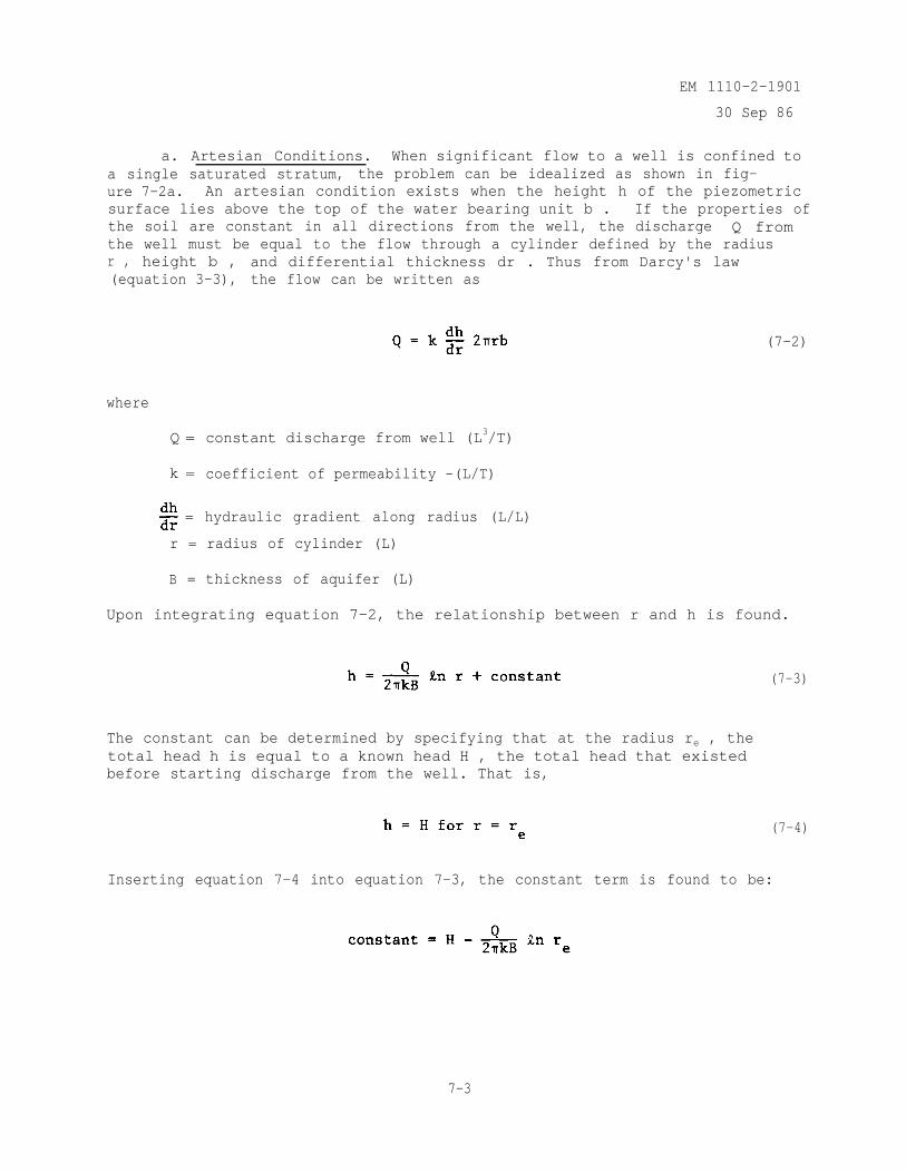
EM 1110-2-1901
30 Sep 86
a. Artesian Conditions. When significant flow to a well is confined toa single saturated stratum, the problem can be idealized as shown in fig-ure 7-2a. An artesian condition exists when the height h of the piezometricsurface lies above the top of the water bearing unit b . If the properties ofthe soil are constant in all directions from the well, the discharge Q fromthe well must be equal to the flow through a cylinder defined by the radiusr , height b , and differential thickness dr . Thus from Darcy's law(equation 3-3), the flow can be written as
(7-2)
where
Q = constant discharge from well (L3/T)
k = coefficient of permeability -(L/T)
= hydraulic gradient along radius (L/L)
r = radius of cylinder (L)
B = thickness of aquifer (L)
Upon integrating equation 7-2, the relationship between r and h is found.
(7-3)
The constant can be determined by specifying that at the radius re , thetotal head h is equal to a known head H , the total head that existedbefore starting discharge from the well. That is,
(7-4)
Inserting equation 7-4 into equation 7-3, the constant term is found to be:
7-3
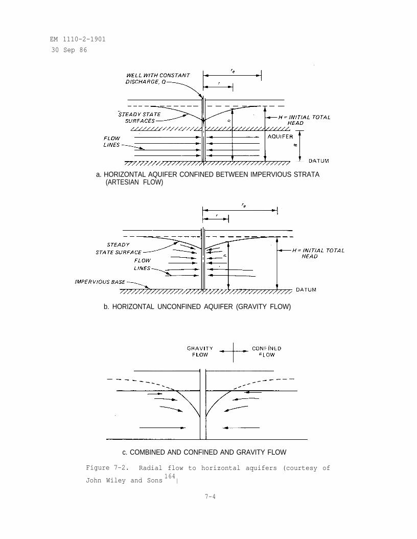
EM 1110-2-1901
30 Sep 86
a. HORIZONTAL AQUIFER CONFINED BETWEEN IMPERVIOUS STRATA(ARTESIAN FLOW)
b. HORIZONTAL UNCONFINED AQUIFER (GRAVITY FLOW)
c. COMBINED AND CONFINED AND GRAVITY FLOW
Figure 7-2. Radial flow to horizontal aquifers (courtesy of
John Wiley and Sons164
)
7-4
EM 1110-2-1901
30 Sep 86
By substituting the constant term into equation 7-3 and combining logarithmicterms, the well equation for confined flow is obtained.
(7-5)
The distance re is often defined as the radius beyond which the well has no
influence or radius of influence.
b. Gravity Flow Conditions. Flow to a well under gravity (figure 7-2b)differs from the confined flow problem in the important aspect that the heightB of the differential cylinder is equal to the variable h . Thus,equation 7-2 must be written as:
(7-6)
which upon integration and substitution of boundary condition gives
(7-7)
The constant term can be evaluated from the condition at the radius of influ-ence r e as was done in equations 7-4 and 7-5. The constant term is givenby:
which when substituted back into equation 7-7 gives the well equation forgravity flow
Development of equation 7-6 is based on the Dupuit assumption (Chapter 4)which limits the applicability of equation 7-7 to those cases where the slopeof the piezometric surface is small (less than 5 percent). The error isgreatest in the vicinity of the well.
7-5
EM 1110-2-190130 Sep 86
c. Combined Artesian and Gravity Flow. When drawdown of the potentio-metric surface becomes large near the well, combined gravity and confined con-ditions can occur (figure 7-2c).
d. Flow to Well Groups (Method of Superposition). The piezometric sur-face h caused by discharge from a group of wells can be determined by super-imposing the solution for the individual wells given by either equation 7-3 or7-6. For multiple wells, flow cannot be idealized by concentric cylinders andthe problem must be stated in terms of the plan coordinates x and y(figure 7-3b). By noting that for a well located at
a general well equation can be written as
(7-8)
where
= potential required at point (x,y) to sustain a discharge Qi froma well at
= hi (confined flow)
= (unconfined or gravity flow)
qi = intensity factor
( confined flow)
(unconfined or gravity flow)
Ci = constant
The head distribution can be determined by summing the individualAs the sum of the constants Ci is a constant, the multiple well
equation can be written as
(7-9)
where n is the number of wells. The constant is determined from a knownvalue of at a specified location. For example, the superposition formula
7-6
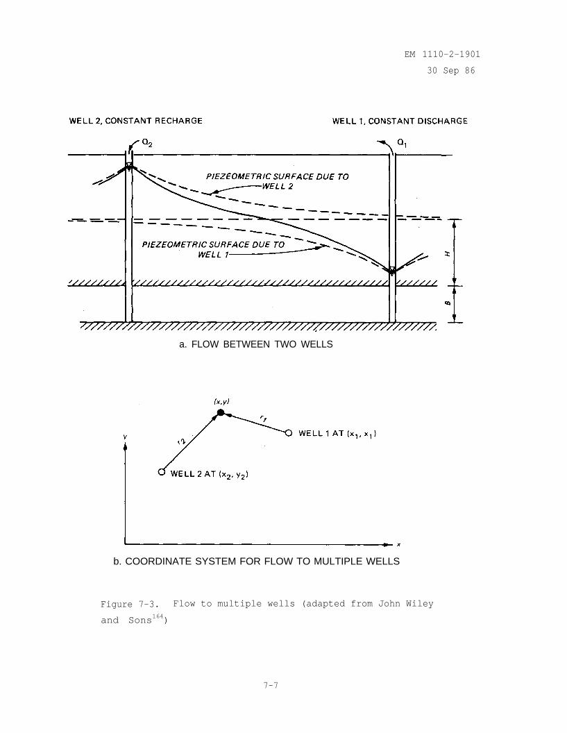
EM 1110-2-1901
30 Sep 86
a. FLOW BETWEEN TWO WELLS
b. COORDINATE SYSTEM FOR FLOW TO MULTIPLE WELLS
Figure 7-3. Flow to multiple wells (adapted from John Wiley
and Sons164)
7-7
EM 1110-7-1901
30 Sep 86
for the wells shown in figure 7-3 would be
At a distance re from both wells h(x,y) = H . The constant term is foundto be
Substituting the above equation into equation 7-9, the well formula for twowells becomes
e. Hydrologic Boundaries (Image Well Method). When there are hydrologicboundaries within the radius of influence of the well, equations 7-3 and 7-7are no longer valid. Examples of boundaries are:
(1) A stream or river which can be idealized as a line source of equalpotential.
(2) A rock bluff line at the edge of an alluvial fill valley which canbe idealized as an impervious boundary.
The superposition of solutions (equation 7-9) can be used to analyze the flownear a boundary by introducing an artificial device called an image well. Animage well is identical to the actual well and located symmetrically on theopposite side of the boundary. The superimposed effect of the real and imagewell for an infinite well is identical to the influence of the real well andboundary. If the real well is a pumping well then a recharging image well isused to represent boundaries such as rivers and a pumping image well is usedto represent an impervious barrier. For either case, the absolute value ofthe flow Q for the image well is equal to that of the real well. For
7-8
EM 1110-2-190130 Sep 86
example, the head distribution created by a discharging well in the vicinity ofa river is identical to that created by the combined influence of a rechargeand discharge well (see figure 7-4). The head distribution created by thedischarge well in an infinite confined aquifer is given by
and by the image recharge well in the infinite aquifer
By superposition, the head distribution for the true actual problem is
(7-10a)
(7-10b)
(7-11)
Note that at the river rI = rR and Thus, constant = H , the
head at the river. Substituting the constant term into equation 7-11, theformula for a single well near a recharge boundary is
To describe the head distribution for confined flow near an impervious boundaryan image discharge well is used (figure 7-4b), By the procedure used above, hwould be obtained as
(7-12)
7-9
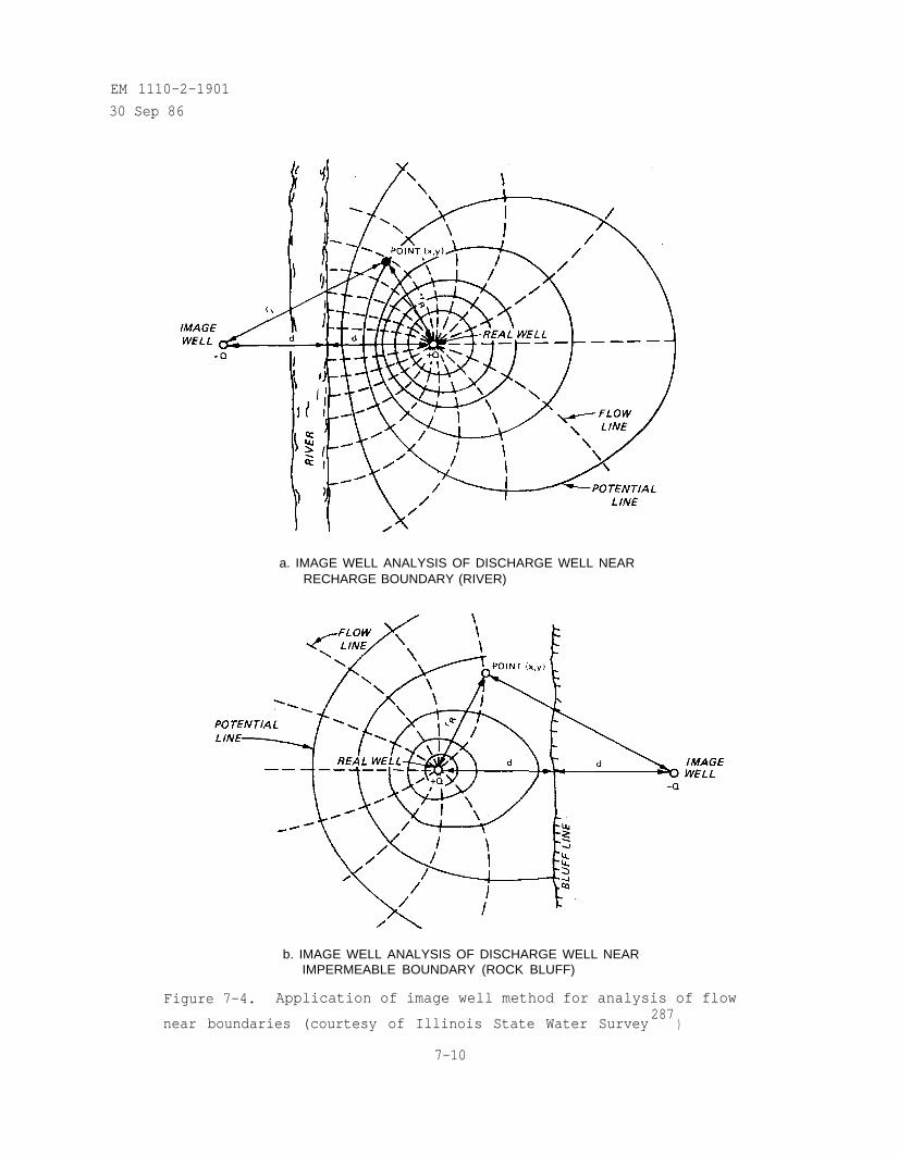
EM 1110-2-1901
30 Sep 86
a. IMAGE WELL ANALYSIS OF DISCHARGE WELL NEARRECHARGE BOUNDARY (RIVER)
b. IMAGE WELL ANALYSIS OF DISCHARGE WELL NEARIMPERMEABLE BOUNDARY (ROCK BLUFF)
Figure 7-4. Application of image well method for analysis of flow
near boundaries (courtesy of Illinois State Water Survey287
)
7-10
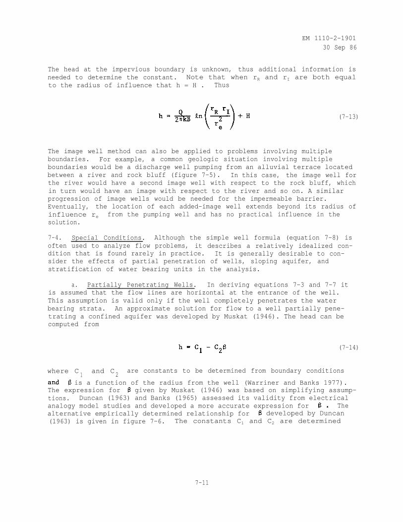
EM 1110-2-190130 Sep 86
The head at the impervious boundary is unknown, thus additional information isneeded to determine the constant. Note that when rR and rI are both equalto the radius of influence that h = H . Thus
(7-13)
The image well method can also be applied to problems involving multipleboundaries. For example, a common geologic situation involving multipleboundaries would be a discharge well pumping from an alluvial terrace locatedbetween a river and rock bluff (figure 7-5). In this case, the image well forthe river would have a second image well with respect to the rock bluff, whichin turn would have an image with respect to the river and so on. A similarprogression of image wells would be needed for the impermeable barrier.Eventually, the location of each added-image well extends beyond its radius ofinfluence re from the pumping well and has no practical influence in thesolution.
7-4. Special Conditions. Although the simple well formula (equation 7-8) isoften used to analyze flow problems, it describes a relatively idealized con-dition that is found rarely in practice. It is generally desirable to con-sider the effects of partial penetration of wells, sloping aquifer, andstratification of water bearing units in the analysis.
a. Partially Penetrating Wells. In deriving equations 7-3 and 7-7 itis assumed that the flow lines are horizontal at the entrance of the well.This assumption is valid only if the well completely penetrates the waterbearing strata. An approximate solution for flow to a well partially pene-trating a confined aquifer was developed by Muskat (1946). The head can becomputed from
(7-14)
where C1
and C2
are constants to be determined from boundary conditions
is a function of the radius from the well (Warriner and Banks 1977).The expression for given by Muskat (1946) was based on simplifying assump-tions. Duncan (1963) and Banks (1965) assessed its validity from electricalanalogy model studies and developed a more accurate expression for Thealternative empirically determined relationship for developed by Duncan(1963) is given in figure 7-6. The constants C1 and C2 are determined
7-11
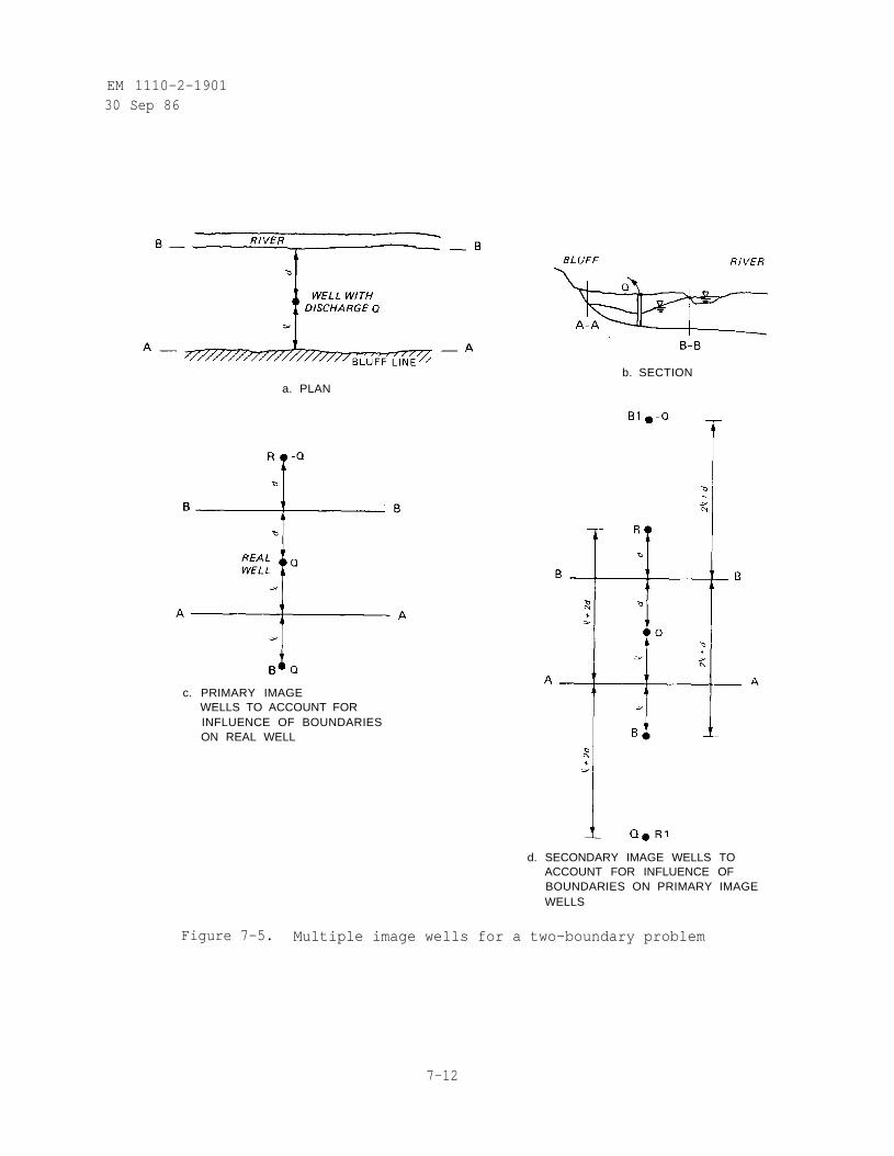
EM 1110-2-190130 Sep 86
b. SECTIONa. PLAN
c. PRIMARY IMAGEWELLS TO ACCOUNT FORINFLUENCE OF BOUNDARIESON REAL WELL
d. SECONDARY IMAGE WELLS TOACCOUNT FOR INFLUENCE OFBOUNDARIES ON PRIMARY IMAGEWELLS
Figure 7-5. Multiple image wells for a two-boundary problem
7-12
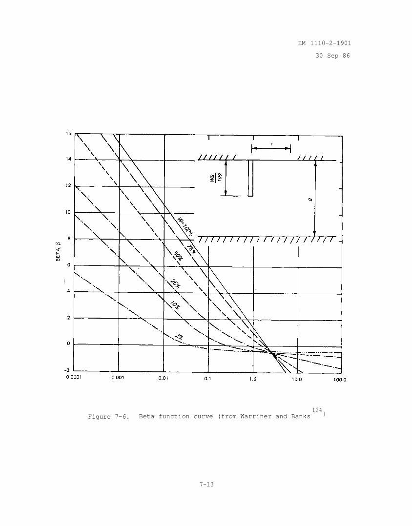
EM 1110-2-1901
30 Sep 86
Figure 7-6. Beta function curve (from Warriner and Banks124
)
7-13
EM 1110-2-1901
30 Sep 86
from the boundary conditions at the well and at the radius of influence as
(7-15)
where
hw = total head at well (L)
= value of at well radius rw (dimensionless)
H = total head at radius of influence re (L)
The well discharge can be determined by using an empirically determined shape
(7-16)
with
where
b. Flows to Groups of Partially Penetrating Wells. An empirical methoddeveloped by Warriner and Banks (1977) provides a means to modify the rela-tionship obtained by superimposing solutions for individual fully penetratingwells for the effects of partial penetration. First, the head at each well iscomputed from the assumption that they fully penetrate the aquifer:
(7-17)
with
7-14
EM 1110-2-1901
30 Sep 86
where
hj = head at well j (L)
c = constant of integration (L)
Qi = discharge from well i (L3/T)
k = coefficient of permeability (L/T)
B = aquifer thickness (L)
a = constant (L)
rij = distance between well i and well j (L)
rwj = radius of well j (L)
N = number of wells in group
In addition, the head at a point on the source boundary is given by:
where H is the head at the source and ris is the distance between
and the source. The drawdown at each well is computed from combiningequations 7-17 and 7-18
well i
with rjj = rwj .
(7-18)
(7-19)
Equation 7-19 gives the drawdown for each well within a group of fullypenetrating wells. The values of Qi required to cause the drawdown
can be determined by solving the system of N equations (7-19) for the Nunknowns Qi . As for the single well, a shape factor can be defined as:
(7-20)
7-15
EM 1110-2-190130 Sep 86
where is the shape factor for each well within a group.factor can be corrected to account for partial penetration by
This shape
(7-21)
By replacing in equation 7-16 with the flow from the well group isgiven as
(7-22)
The computations required to evaluate equations 7-19 through 7-22 are straight-forward though they are time consuming for large well groups. Warriner andBanks (1977) provide a FORTRAN code to compute discharge and drawdowns forpartially penetrating well groups within an arbitrarily shaped source boundary.
c. Wells in Sloping Aquifer. If the regional potentiometric surfacehas a significant slope, the effect of superimposing the initial regionalgradient on the well drawdowns must be considered. For example, when pumpingfrom floodplain locations, the existing piezometric gradient from upland areasto the river may be as great as those caused by pumping from the well. Thesignificant parameters for confined flow to a single well are shown infigure 7-7. At a large distance from the well, the regional flow net wouldnot be affected. All flow into the well would be contained within the streamlines separated by the dimension f . Thus by Darcy's law for one-dimensionalflow
where
Q = discharge from well (L3/T)
k = permeability (L/T)
h1 = total head (L) for regional flow alone
(7-23)
7-16
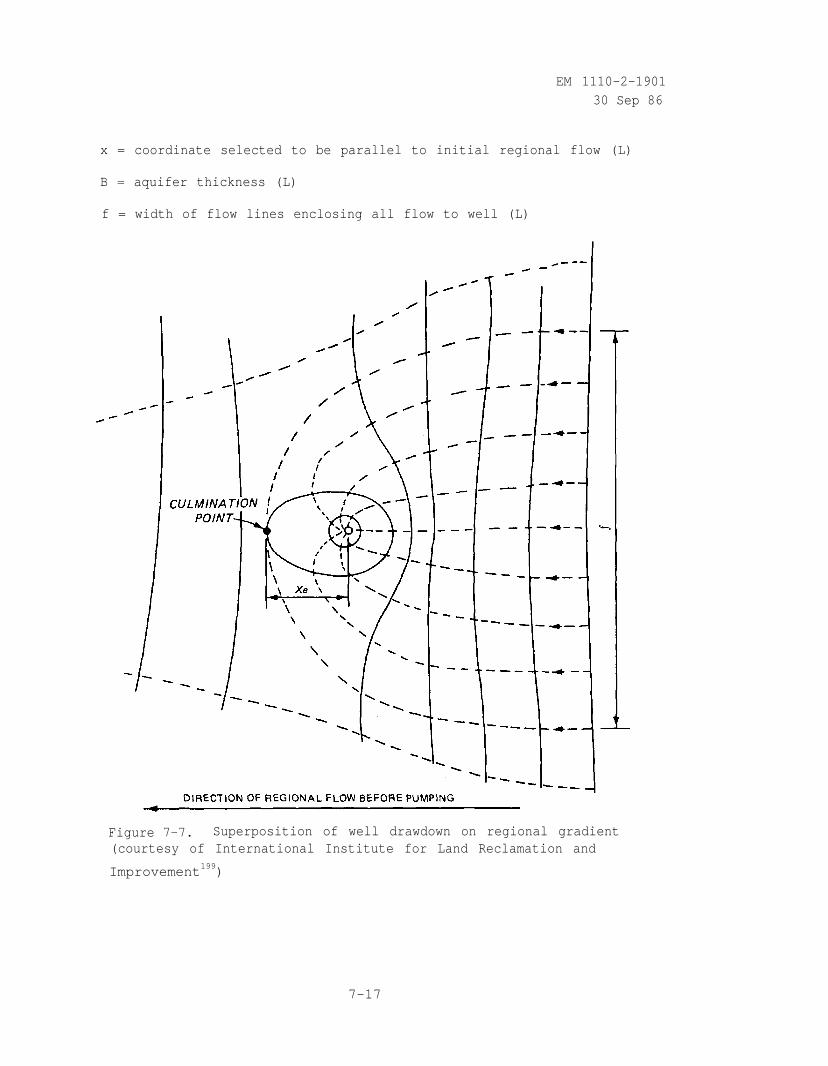
EM 1110-2-190130 Sep 86
x = coordinate selected to be parallel to initial regional flow (L)
B = aquifer thickness (L)
f = width of flow lines enclosing all flow to well (L)
Figure 7-7. Superposition of well drawdown on regional gradient(courtesy of International Institute for Land Reclamation and
Improvement199)
7-17
EM 1110-2-1901
30 Sep 86
The corresponding differential equation for the well would be
(7-24)
where
= total head due to flow to well
At a distance Xe downgradient from the well, a groundwater divide develops
(culmination point) at which
In view of equations 7-23 and 7-24
or
By substitution of equation 7-26 into equation 7-23
(7-25)
(7-26)
(7-27)
By integrating equations 7-24 and 7-27
(7-28)
7-18
EM 1110-2-1901
30 Sep 86
and superimposing the effects
(7-29)
The distance Xe can be removed from the expression by substitution ofequation 7-27
(7-30)
where i = the regional slope of the aquifer.
For conditions of unconfined flow, the regional gradient would be defined by aparabola
which when combined with the well equations for unconfined flow gives
(7-31)
d. Layered Aquifers. Natural soils often occur in layers and a wellmay penetrate units having different permeabilities. If flow to the well ishorizontal, the simple well equations can be used by assigning an averagevalue of permeability given by
where
km = horizontal permeability of layer m
dm = thickness of layer m
d = total thickness of layers
7-19
(7-32)
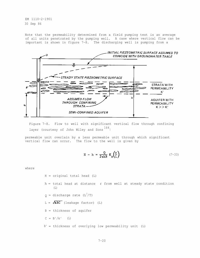
EM 1110-2-1901
30 Sep 86
Note that the permeability determined from a field pumping test is an averageof all units penetrated by the pumping well. A case where vertical flow can beimportant is shown in figure 7-8. The discharging well is pumping from a
Figure 7-8. Flow to well with significant vertical flow through confining
layer (courtesy of John Wiley and Sons164
)
permeable unit overlain by a less permeable unit through which significantvertical flow can occur. The flow to the well is given by
(7-33)
where
H = original total head (L)
h = total head at distance r from well at steady state condition(L)
Q = discharge rate (L3/T)
L = (leakage factor) (L)
B = thickness of aquifer
C = B'/k' (L)
B' = thickness of overlying low permeability unit (L)
7-20
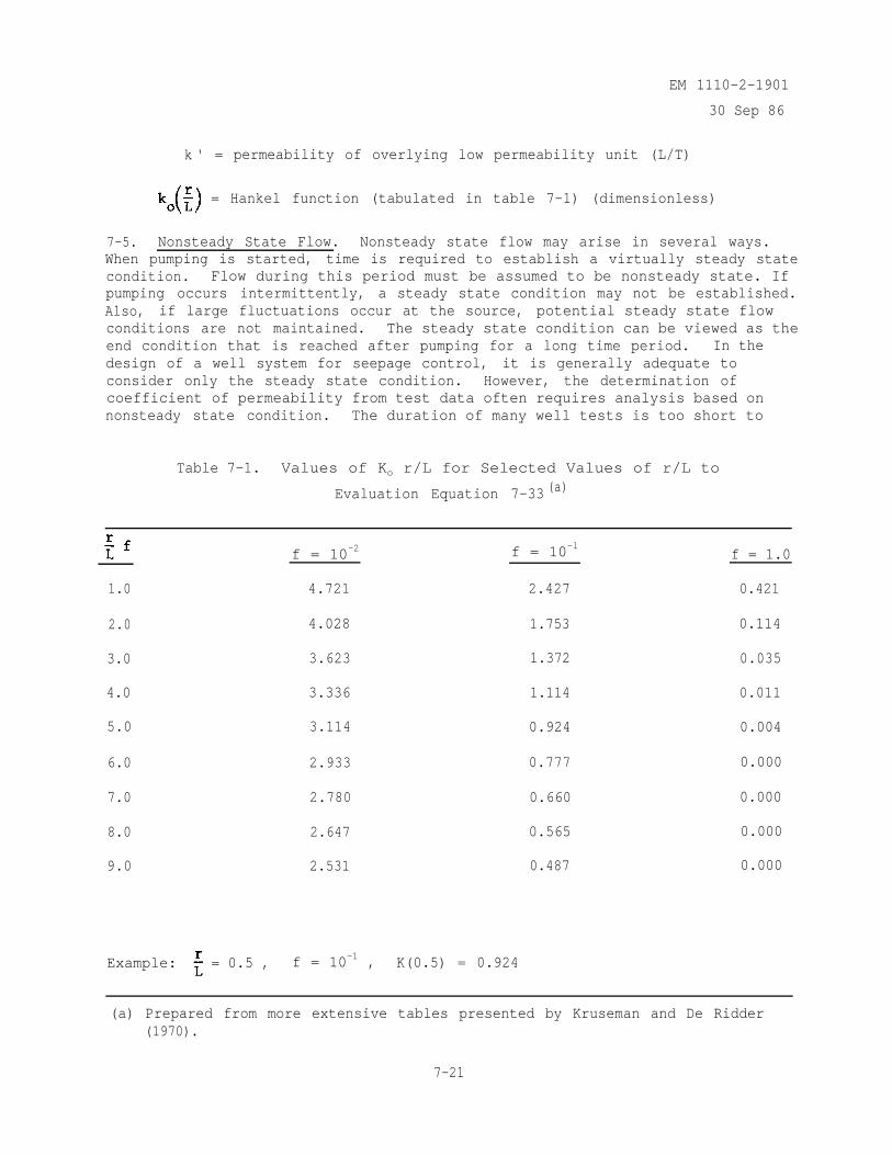
EM 1110-2-1901
30 Sep 86
k ' = permeability of overlying low permeability unit (L/T)
= Hankel function (tabulated in table 7-1) (dimensionless)
7-5. Nonsteady State Flow. Nonsteady state flow may arise in several ways.When pumping is started, time is required to establish a virtually steady statecondition. Flow during this period must be assumed to be nonsteady state. Ifpumping occurs intermittently, a steady state condition may not be established.Also, if large fluctuations occur at the source, potential steady state flowconditions are not maintained. The steady state condition can be viewed as theend condition that is reached after pumping for a long time period. In thedesign of a well system for seepage control, it is generally adequate toconsider only the steady state condition. However, the determination ofcoefficient of permeability from test data often requires analysis based onnonsteady state condition. The duration of many well tests is too short to
Table 7-1. Values of Ko r/L for Selected Values of r/L to
Evaluation Equation 7-33 (a)
1.0
2.0
3.0
4.0
5.0
6.0
7.0
8.0
9.0
4.721
4.028
3.623
3.336
3.114
2.933
2.780
2.647
2.531
2.427 0.421
1.753 0.114
1.372 0.035
1.114 0.011
0.924 0.004
0.777 0.000
0.660 0.000
0.565 0.000
0.487 0.000
f = 10-2 f = 10-l
Example: = 0.5 , f = 10-1 , K(0.5) = 0.924
f = 1.0
(a) Prepared from more extensive tables presented by Kruseman and De Ridder(1970).
7-21
EM 1110-2-1901
30 Sep 86
reliably establish the steady state condition. Also, in practice, hydrologicboundaries may be present within the steady state radius of influence. Ineither case the use of the steady state flow equations could lead to substan-tial error in determining the permeability.
a. Nonsteady State Confined Flow. Theis (1935) developed the followingrelationship for nonsteady state flow in a confined aquifer (Davis and DeWeist1966):
(7-34)
where
Q = constant discharge rate (L3/T)
k = permeability (L/T)
B = thickness of aquifer (L)
W(u) = function given in table 7-2
The parameter u is given by
(7-35)
where
r = radius from well (L)
S = storage coefficient (dimensionless)
t = time from start of pumping (T)
The storage coefficient S represents the amount of water removed from stor-age as a result of consolidation of the aquifer and expansion of water inresponse to the decline in head. Physically S is given by
(7-36)
7-22
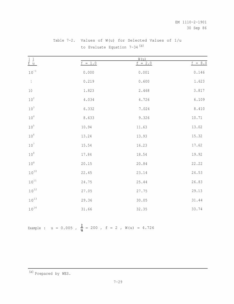
EM 1110-2-1901
30 Sep 86
Table 7-2. Values of W(u) for Selected Values of 1/u
to Evaluate Equation 7-34 (a)
1 1 W(u)f u f = 1.0 f = 2.0 f = 8.0
10-1 0.000 0.001 0.146
1 0.219 0.600 1.623
10 1.823 2.468 3.817
102 4.034 4.726 6.109
103 6.332 7.024 8.410
104 8.633 9.326 10.71
105 10.94 11.63 13.02
106 13.24 13.93 15.32
107 15.54 16.23 17.62
108 17.84 18.54 19.92
10g 20.15 20.84 22.22
1010 22.45 23.14 24.53
1011 24.75 25.44 26.83
1012 27.05 27.75 29.13
1013 29.36 30.05 31.44
1014 31.66 32.35 33.74
Example : u = 0.005 , = 200 , f = 2 , W(u) = 4.726
(a) Prepared by WES.
7-29
EM 1110-2-190130 Sep 86
where
= mass density fluid (m/L3)
g = acceleration of gravity (L/T2)
B = thickness of aquifer
= bulk compressibility of aquifer (LT2/M)
n = porosity (dimensionless)
= bulk compressibility of fluid (LT2/M)
The determination of the aquifer properties kb and S from equation 7-34requires a complete drawdown versus time history for each observationpiezometer. The Theis method for data analysis is based on the logarithmicrepresentation of equations 7-34 and 7-35
From the equations above it is seen that if Q is constant that log(H - h)
varies with log(r2/t) in the same way as log [W(u)] varies with log (u)regardless of the units used. Therefore, it should be possible to superimposethe data curve on the theoretical curve because the two curves are offset fromeach other only by the constant terms log and log S/4kB . By deter-mining the value of the offsets from the superimposed curves, kb and S canbe determined. The computation consists of the following steps:
(1) A plot is made of W(u) (log scale) versus u (log scale). Thisplot is referred to as the type curve.
(2) For each observation well, a plot is made of drawdown H - h (log
scale) versus (log scale).
(3) Superimpose the test data over the type curve in such a way thatthe drawdown data best fit the type curve (figure 7-9). The coordinate axesof the two curves should be kept parallel.
(4) Determine the values W(u) , u , H - h , and r2/t from anarbitrarily chosen matching point on the two curves.
7-24
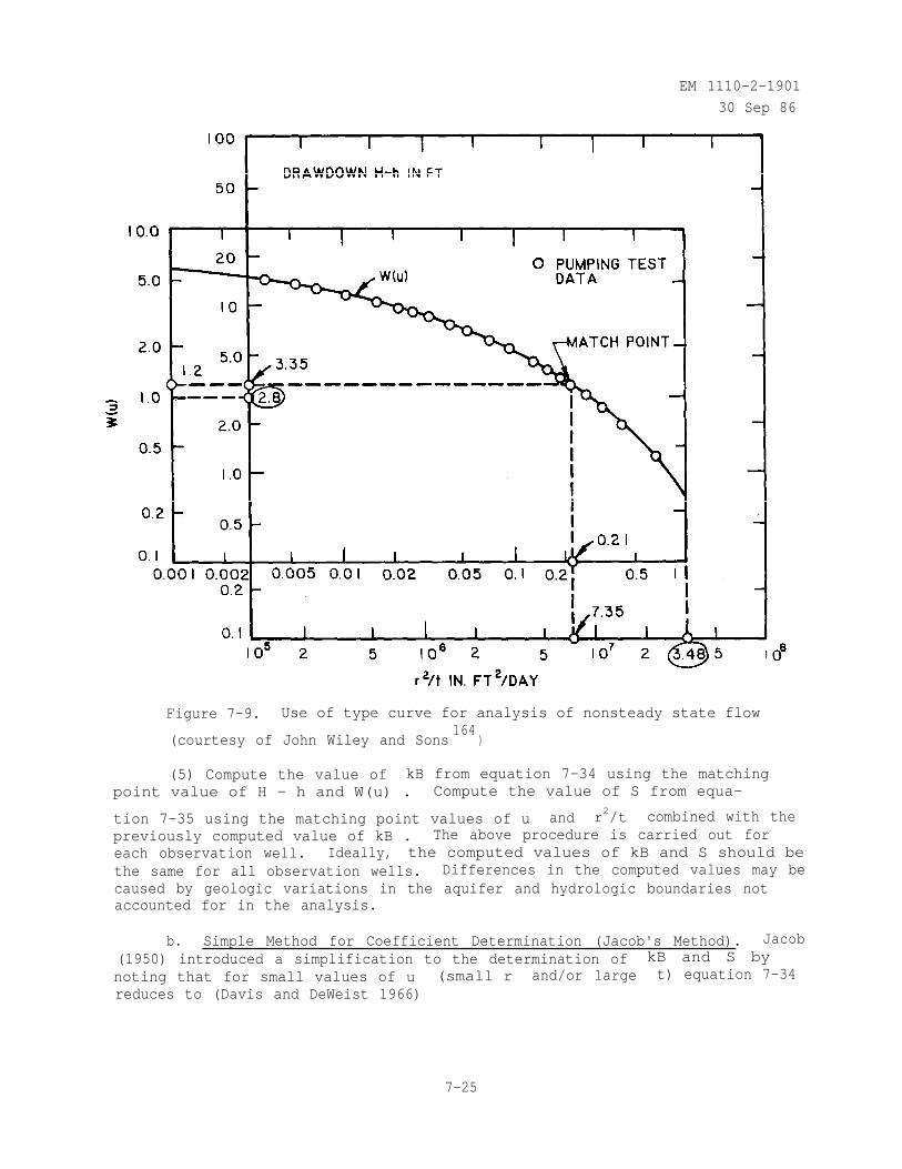
EM 1110-2-1901
30 Sep 86
Figure 7-9. Use of type curve for analysis of nonsteady state flow
(courtesy of John Wiley and Sons164
)
(5) Compute the value of kB from equation 7-34 using the matchingpoint value of H - h and W(u) . Compute the value of S from equa-
tion 7-35 using the matching point values of u and r2/t combined with thepreviously computed value of kB . The above procedure is carried out foreach observation well. Ideally, the computed values of kB and S should bethe same for all observation wells. Differences in the computed values may becaused by geologic variations in the aquifer and hydrologic boundaries notaccounted for in the analysis.
b. Simple Method for Coefficient Determination (Jacob's Method). Jacob(1950) introduced a simplification to the determination of kB and S bynoting that for small values of u (small r and/or large t) equation 7-34reduces to (Davis and DeWeist 1966)
7-25
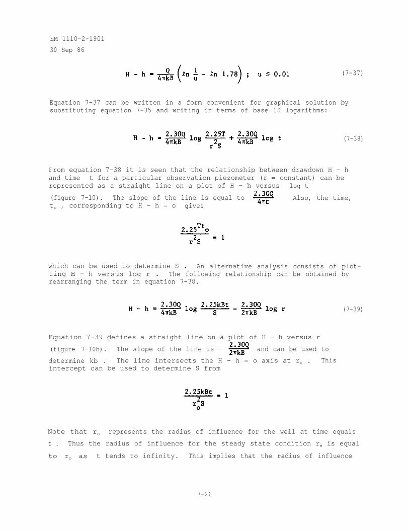
EM 1110-2-1901
30 Sep 86
(7-37)
Equation 7-37 can be written in a form convenient for graphical solution bysubstituting equation 7-35 and writing in terms of base 10 logarithms:
(7-38)
From equation 7-38 it is seen that the relationship between drawdown H - hand time t for a particular observation piezometer (r = constant) can berepresented as a straight line on a plot of H - h versus log t
(figure 7-10). The slope of the line is equal to Also, the time,to , corresponding to H - h = o gives
which can be used to determine S . An alternative analysis consists of plot-ting H - h versus log r . The following relationship can be obtained byrearranging the term in equation 7-38.
Equation 7-39 defines a straight line on a plot of H - h versus r
(figure 7-10b). The slope of the line is - and can be used to
determine kb . The line intersects the H - h = o axis at ro . Thisintercept can be used to determine S from
(7-39)
Note that ro represents the radius of influence for the well at time equals
t . Thus the radius of influence for the steady state condition re is equal
to ro as t tends to infinity. This implies that the radius of influence
7-26
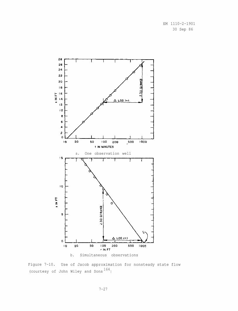
EM 1110-2-1901
30 Sep 86
a. One observation well
b. Simultaneous observations
Figure 7-10. Use of Jacob approximation for nonsteady state flow
(courtesy of John Wiley and Sons 164)
7-27
EM 1110-2-1901
30 Sep 86
expands indefinitely and cannot be defined. However, the value of re
selected has a relatively small influence on computed drawdowns near the welland equation 7-39 can be used to determine reasonable values for re .
Yield).c. Nonsteady Unconfined Flow with Vertical Gravity Drainage (Delayed
Initial response (generally after first few minutes of pumping) isgiven by (Kruseman and DeRidder 1970)
(7-40)
where
SA = storage coefficient for instantaneous release of water fromstorage
W(uA , r/B) = Boulton well function (figure 7-11a)
r/B = formation constant to be determined from piping test data
Later time response is given by
where
Sy = specific yield
W(uy , r/B) = delayed yield well function
The application of equations 7-40 and 7-41 through use of a type-curve issimilar to that of equation 7-34. The following should also be noted:
(7-41)
(1) Type curves for several values of r/B should be plotted. Thecurve giving the best fit to the initial time-drawdown data is used toestimate r/B .
7-28
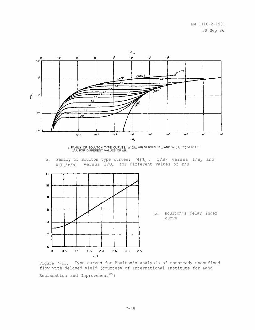
EM 1110-2-1901
30 Sep 86
a FAMILY OF BOULTON TYPE CURVES: W (UA,1/Uy FOR DIFFERENT VALUES OF r/B.
r/B) VERSUS 1/uA AND W (Uy, r/b) VERSUS
a. Family of Boulton type curves:W(Uy/r/b) versus 1/Uy
W(UA , r/B) versus 1/uA andfor different values of r/B
b. Boulton's delay indexcurve
Figure 7-11. Type curves for Boulton's analysis of nonsteady unconfinedflow with delayed yield (courtesy of International Institute for Land
Reclamation and Improvement199)
7-29
EM 1110-2-1901
30 Sep 86
(2) The time-drawdown data overlay may be moved to obtain the best fitfor the latter time-drawdown data. Both initial time and latter time fitsshould give the same value of r/B and kB .
(3) Eventually, the effects of vertical gravity drainage become negli-gible and the latter time curve merges with the Theis curve. The time-coordinate where the two curves merge is determined from Boulton's delay-indexcurve (figure 7-11b).
(4) A number of type-curve solutions to the problem of nonsteady uncon-fined flow to wells have been developed (Fetter 1980). For example, Neuman(1975) presented a type-curve method similar to Boulton's that accounts foranisotropy of the aquifer.
d. Nonsteady Confined Flow with Vertical Drainage Through ConfiningLayer (Leaky Aquifer). The leaky aquifer equation for nonsteady flow is basedon the assumptions that flow to the well is horizontal and vertical flow isrestricted to seepage through the confining layer. These assumptions areidentical to those made for the steady state case described by equation 7-33.The drawdown is given by
where
r2Su=4kBt
r = radius from well (L)
S = storage coefficient (dimensionless)
k = permeability (L/T)
t = time from start of pumping (T)
L = leakage factor (L) =
B = thickness of aquifer (L)
B ' = thickness of confining unit (L)
k' = permeability of confining unit (L/T)
(7-42)
W(u , r/L) = well function given in figure 7-12
7-30
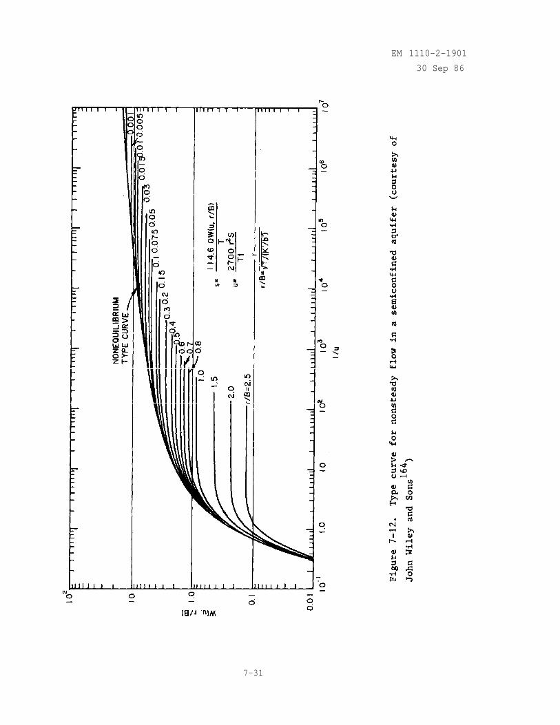
EM 1110-2-1901
30 Sep 86
7-31
EM 1110-2-1901
30 Sep 86
The application of the type curve method for the leaky aquifer problem is simi-lar to the application to the delayed yield problem. The time-drawdown dataare matched to the standard type curve with the curve giving the best fit beingused to estimate r/B .
e. Nonsteady Unconfined Flow with Little Vertical Drainage. If thedelayed response component of the drawdown is small, the Theis equation(equation 7-34) can be used to analyze the flow by inserting a "corrected"drawdown into the flow equation. The corrected drawdown is given by
(7-43)
f. Nonsteady Flow with Hydrologic Boundaries. The method of super-position presented for steady-state flow problems (equation 7-9) is applicableto nonsteady flow problems. Therefore, the image well method can be used toinvestigate the effects of hydrologic boundaries. For example, the image wellanalysis for a discharging well near a river (recharge boundary) is (Davis andDewiest 1966)
where
rR = radius from real well (L)
rI = radius from image well (L)
k = coefficient of permeability (L/T)
S = storage coefficient (dimensionless)
(7-44)
B = aquifer thickness (L)
t = time from start of pumping (T)
7-32
EM 1110-2-1901
30 Sep 86
Note, then, when the function W(u) can be replaced with a logarithmicapproximation, as in the Jacob's method (equation 7-37), equation 7-44 can beapproximated as
(7-45)
From equation 7-45 it is seen that as u becomes small, flow becomes virtuallysteady state (compare equation 7-45 with the steady state case, equation 7-11).Thus the presence of a recharge boundary in an aquifer tends to shorten thetime needed to reach steady state (Davis and Dewiest 1966).
7-33
EM 1110-2-1901
30 Sep 86
CHAPTER 8SEEPAGE CONTROL IN EMBANKMENTS
8-1. General. All earth and rock-fill dams are subject to seepage throughthe embankment, foundation, and abutments. Seepage control is necessary toprevent excessive uplift pressures, instability of the downstream slope, pip-ing through the embankment and/or foundation, and erosion of material bymigration into open joints in the foundation and abutments. The purpose ofthe project, i.e., long-term storage, flood control, etc., may impose limita-tions on the allowable quantity of seepage.
8-2. Methods for Seepage Control. The three methods for seepage control inembankments are flat slopes without drains, embankment zonation, and vertical(or inclined) and horizontal drains.
8-3. Flat Slopes Without Drains. For some dams constructed with impervioussoils having flat embankment slopes and infrequent, short duration, highreservoir levels, the phreatic surface may be contained well within the down-stream slope and escape gradients may be sufficiently low to prevent pipingfailure. For these dams, when it can be assured that variability in thecharacteristics of borrow materials will not result in adverse stratificationin the embankment; no vertical or horizontal drains are required to controlseepage through the embankment. A horizontal drain may still be required forcontrol of underseepage (see Chapter 9). Examples of dams constructed withflat slopes without vertical or horizontal drains are Aquilla Dam, Aubrey Dam,and Lakeview Dam (U. S. Army Engineer District, Fort Worth 1976a, 1976b, 1980).Figure 8-1 shows the analysis of through embankment seepage for Aubrey Dam, Texas (now called Ray Roberts Dam). As shown in figure 8-1a, this is a zonedembankment with relatively flat slopes due to a weak stratum in the founda-tion. The slopes could be steepened from IV:10.6H to lV:8H if the weak foun-dation gains shear strength due to consolidation during construction (the damis scheduled for completion in 1988). A 3-ft-thick horizontal drainage blanketand collector system will be provided under the downstream embankment fromsta 136+00 to sta 142+60 to control any seepage through the foundation. Forthe analysis of through embankment seepage, shown in figure 8-1b, the steadystate phreatic surface was developed graphically for the conservation pool byconsidering a homogeneous nonisotropic embankment and an impervious foundation.Since the escape seepage gradients were computed to be less than 0.3 to 0.4(see paragraph 4.9b), it was concluded that no vertical or horizontal drainswere required.
8-4. Zoning Embankments.
a. General. Embankments are zoned to use as much material as possiblefrom required excavation and from borrow areas with the shortest haul dis-tances and the least wastage and at the same time maintain stability and con-trol seepage. The different zones of an embankment are shown in figure 8-2.For most effective control of through seepage and seepage during reservoirdrawdown, the permeability should progressively increase from the core outtoward each slope as shown in figure 8-2 (EM 1110-2-2300).
8-1
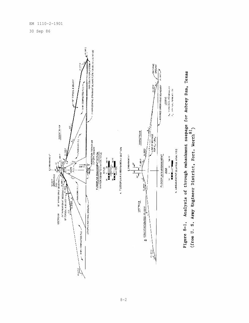
EM 1110-2-1901
30 Sep 86
8-2
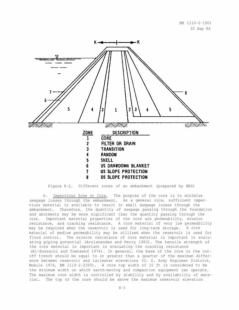
EM 1110-2-1901
30 Sep 86
Figure 8-2. Different zones of an embankment (prepared by WES)
b. Impervious Zone or Core. The purpose of the core is to minimizeseepage losses through the embankment. As a general rule, sufficient imper-vious material is available to result in small seepage losses through theembankment. Therefore, the quantity of seepage passing through the foundationand abutments may be more significant than the quantity passing through thecore. Important material properties of the core are permeability, erosionresistance, and cracking resistance. A core material of very low permeabilitymay be required when the reservoir is used for long-term storage. A corematerial of medium permeability may be utilized when the reservoir is used forflood control. The erosion resistance of core material is important in evalu-ating piping potential (Arulanandan and Perry 1983). The tensile strength ofthe core material is important in evaluating the cracking resistance(Al-Hussaini and Townsend 1974). In general, the base of the core or the cut-off trench should be equal to or greater than a quarter of the maximum differ-ence between reservoir and tailwater elevations (U. S. Army Engineer District,Mobile 1976, EM 1110-2-2300). A core top width of 10 ft is considered to bethe minimum width on which earth-moving and compaction equipment can operate.The maximum core width is controlled by stability and by availability of mate-rial. The top of the core should be above the maximum reservoir elevation
8-3
EM 1110-2-190130 Sep 86
but below the bottom of the frost zone, A vertical core located near thecenter of the dam is performed over an inclined upstream core because theformer provides higher contact pressure between the core and foundation toprevent leakage, greater stability under earthquake loading (Sherad 1966,1967), and better access for remedial seepage control. An inclined upstreamcore allows the downstream portion of the embankment to be placed first and thecore later and reduces the possibility of hydraulic fracturing (Nobari, Lee,and Duncan 1973).
c. Filter Zones. Filters may be required in various locations in earthdams such as vertical (or inclined) and horizontal drains within the down-stream section of the embankment as shown in figure 8-2, around outlet con-duits passing under the downstream portion of the embankment, under concretestructures such as stilling basins, around relief wells, beneath riprap wheredrawdown may occur, and between the embankment and abutment. Important prop-erties of the filter material are gradation, compacted density, and permeabil-ity. Filters are designed to permit free passage of water and prevent migra-tion of fines through the filter as discussed in Appendix D. The averagein-place relative density of the filter should be at least 85 percent and noportion of the filter should have a relative density less than 80 percent(EM 1110-2-2300). This requirement applies to vertical (or inclined) andhorizontal drains and filters under concrete structures but not to beddinglayers under riprap. Special care must be taken to assure that compaction doesnot degrade the filter material (by grain breakage and/or segregation) andreduce its permeability. When the filter material is sand or contains signifi-cant portions of sand sizes, the material should be maintained in as saturateda condition as possible during compaction to prevent bulking. The dischargecapacity of the filter zones should be determined in dimensioning the filters(Cedergren 1977). The filter material should pass the 3-in. screen for mini-mizing particle segregation and bridging during placement. As discussed pre-viously in Chapter 2 (see figure 2-12), the permeability of sands and gravelsvaries significantly with the amount and type of fines (material smaller thanthe No. 200 sieve) present. Also, the amount and type of fines presentinfluence the capacity of a filter to self-heal by collapsing any cracks withinthe filter (see figure 8-3). Therefore, the maximum percent fines and type(silt, clay, etc.) to be allowed in the filter of an earth dam must be shown
to be sufficiently pervious by laboratory filter tests (1) and self healing bycollapse tests (Vaughn 1978). If vibration is present, such as in the vicinityof a stilling basin or powerhouse, the. laboratory filter tests should be con-ducted with vibration effects. If the base material to be protected isdispersive, large-scale box filter tests will be required (McDaniel and Decker1979, Bordeaux and Imaizumi 1977, and Logani and Lhez 1979). The procedure touse in identifying dispersive clays is given in EM 1110-2-1906. Generally, twoor more filter zones, each with a uniform or narrow gradation (sand, peagravel, etc.) are preferable to a single well-graded filter zone which oftenbecomes segregated during processing, stockpiling, and placement. Care must
(1) Laboratory filter tests are not a routine laboratory test. Standard test-ing procedures have not been developed. The conduct of laboratory filtertests should be under the direction of a specialist and should be carriedout in a research laboratory.
8-4
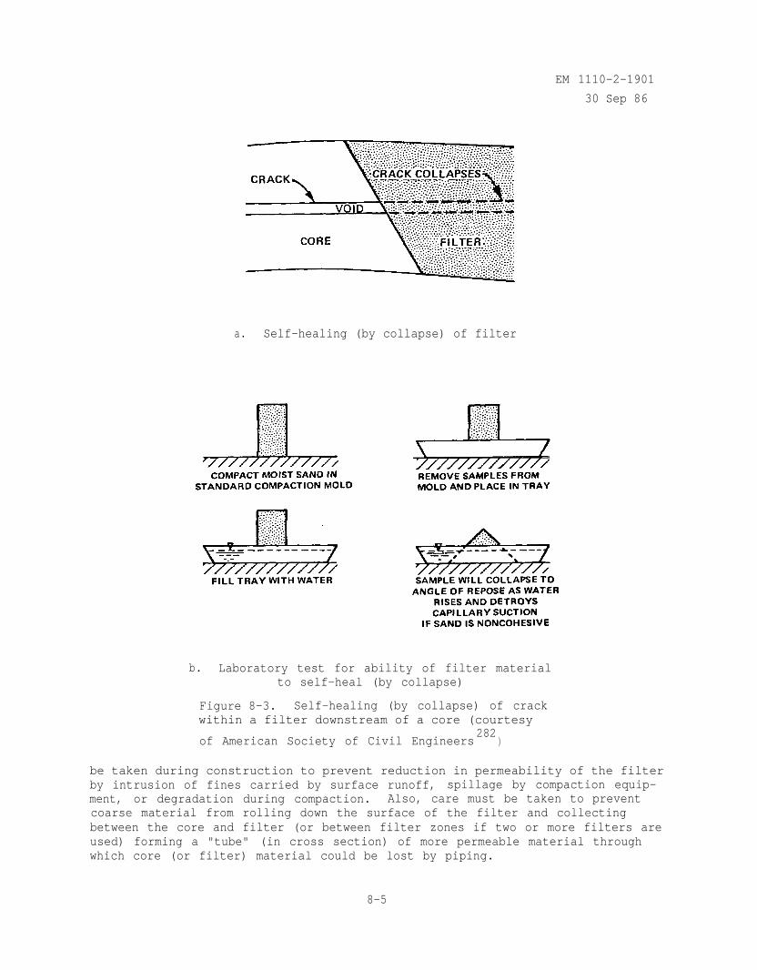
EM 1110-2-1901
30 Sep 86
a. Self-healing (by collapse) of filter
b. Laboratory test for ability of filter materialto self-heal (by collapse)
Figure 8-3. Self-healing (by collapse) of crackwithin a filter downstream of a core (courtesy
of American Society of Civil Engineers282
)
be taken during construction to prevent reduction in permeability of the filterby intrusion of fines carried by surface runoff, spillage by compaction equip-ment, or degradation during compaction. Also, care must be taken to preventcoarse material from rolling down the surface of the filter and collectingbetween the core and filter (or between filter zones if two or more filters areused) forming a "tube" (in cross section) of more permeable material throughwhich core (or filter) material could be lost by piping.
8-5
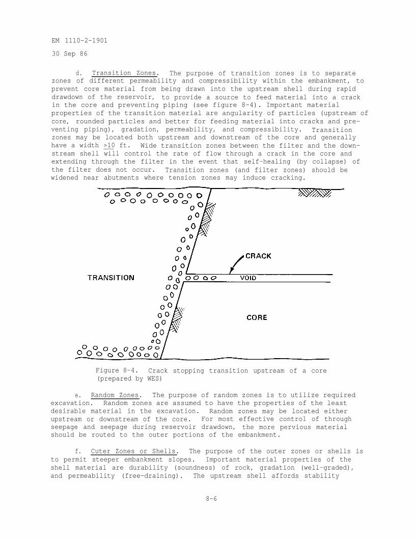
EM 1110-2-1901
30 Sep 86
d. Transition Zones. The purpose of transition zones is to separatezones of different permeability and compressibility within the embankment, toprevent core material from being drawn into the upstream shell during rapiddrawdown of the reservoir, to provide a source to feed material into a crackin the core and preventing piping (see figure 8-4). Important materialproperties of the transition material are angularity of particles (upstream ofcore, rounded particles and better for feeding material into cracks and pre-venting piping), gradation, permeability, and compressibility. Transitionzones may be located both upstream and downstream of the core and generallyhave a width >10 ft. Wide transition zones between the filter and the down-stream shell will control the rate of flow through a crack in the core andextending through the filter in the event that self-healing (by collapse) ofthe filter does not occur. Transition zones (and filter zones) should bewidened near abutments where tension zones may induce cracking.
Figure 8-4. Crack stopping transition upstream of a core(prepared by WES)
e. Random Zones. The purpose of random zones is to utilize requiredexcavation. Random zones are assumed to have the properties of the leastdesirable material in the excavation. Random zones may be located eitherupstream or downstream of the core. For most effective control of throughseepage and seepage during reservoir drawdown, the more pervious materialshould be routed to the outer portions of the embankment.
f. Cuter Zones or Shells. The purpose of the outer zones or shells isto permit steeper embankment slopes. Important material properties of theshell material are durability (soundness) of rock, gradation (well-graded),and permeability (free-draining). The upstream shell affords stability
8-6
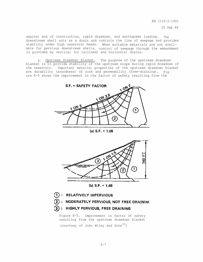
EM 1110-2-1901
30 Sep 86
against end of construction, rapid drawdown, and earthquake loading. Thedownstream shell acts as a drain and controls the line of seepage and providesstability under high reservoir heads. When suitable materials are not avail-able for pervious downstream shells, control of seepage through the embankmentis provided by vertical (or inclined) and horizontal drains.
g. Upstream Drawdown Blanket. The purpose of the upstream drawdownblanket is to provide stability of the upstream slope during rapid drawdown ofthe reservoir. Important material properties of the upstream drawdown blanketare durability (soundness) of rock and permeability (free-draining). Fig-ure 8-5 shows the improvement in the factor of safety resulting from the
Figure 8-5. Improvement in factor of safetyresulting from the upstream drawdown blanket
(courtesy of John Wiley and Sons155)
8-7
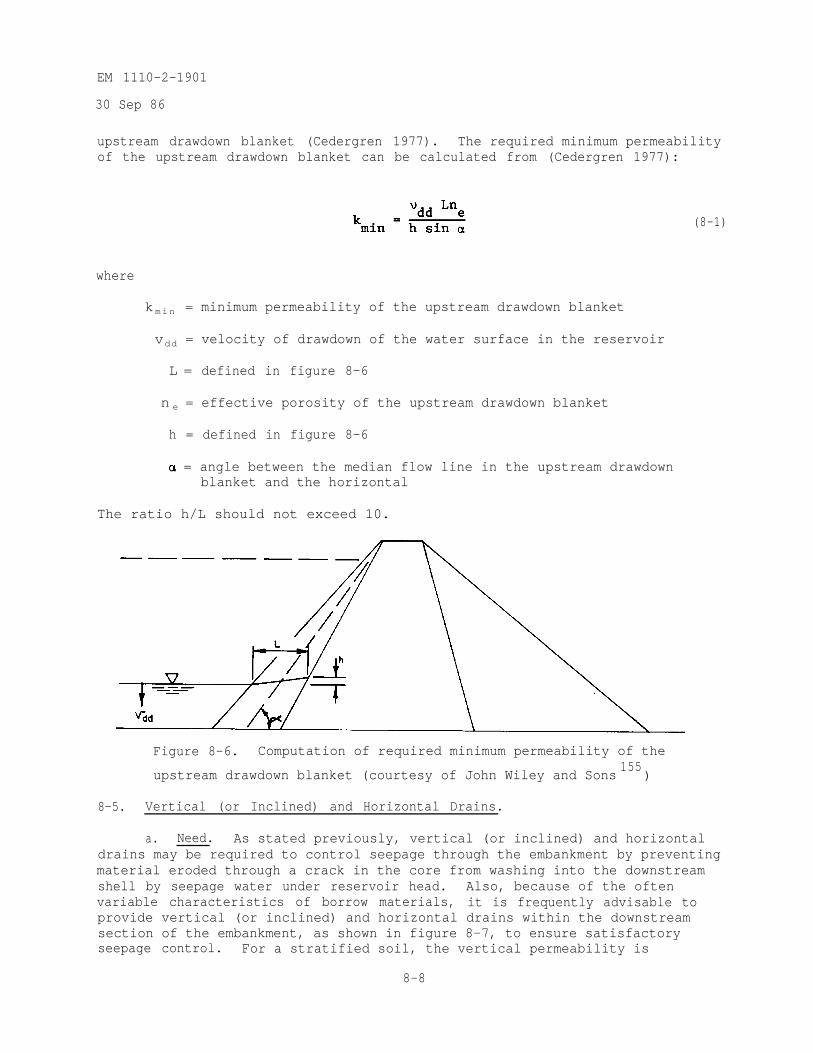
EM 1110-2-1901
30 Sep 86
upstream drawdown blanket (Cedergren 1977). The required minimum permeabilityof the upstream drawdown blanket can be calculated from (Cedergren 1977):
where
kmin = minimum permeability of the upstream drawdown blanket
vdd = velocity of drawdown of the water surface in the reservoir
L = defined in figure 8-6
n e = effective porosity of the upstream drawdown blanket
h = defined in figure 8-6
= angle between the median flow line in the upstream drawdownblanket and the horizontal
The ratio h/L should not exceed 10.
(8-1)
Figure 8-6. Computation of required minimum permeability of the
upstream drawdown blanket (courtesy of John Wiley and Sons155
)
8-5. Vertical (or Inclined) and Horizontal Drains.
a. Need. As stated previously, vertical (or inclined) and horizontaldrains may be required to control seepage through the embankment by preventingmaterial eroded through a crack in the core from washing into the downstreamshell by seepage water under reservoir head. Also, because of the oftenvariable characteristics of borrow materials, it is frequently advisable toprovide vertical (or inclined) and horizontal drains within the downstreamsection of the embankment, as shown in figure 8-7, to ensure satisfactoryseepage control. For a stratified soil, the vertical permeability is
8-8
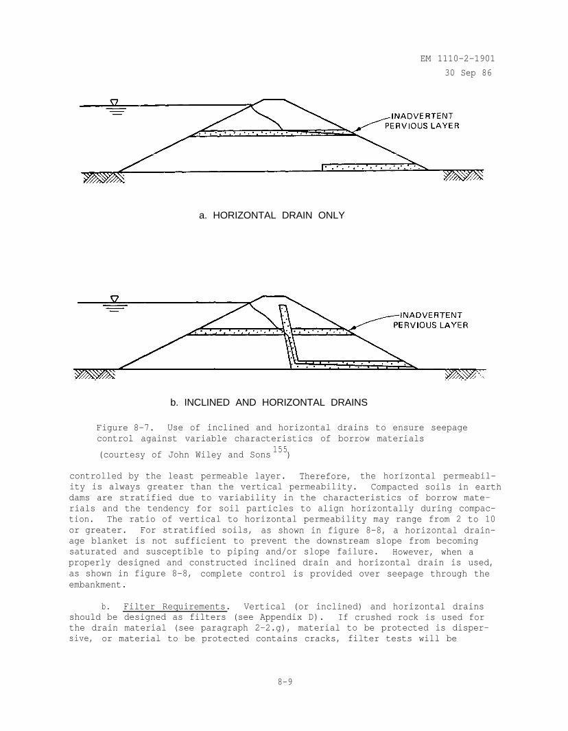
EM 1110-2-1901
30 Sep 86
a. HORIZONTAL DRAIN ONLY
b. INCLINED AND HORIZONTAL DRAINS
Figure 8-7. Use of inclined and horizontal drains to ensure seepagecontrol against variable characteristics of borrow materials
(courtesy of John Wiley and Sons155
)
controlled by the least permeable layer. Therefore, the horizontal permeabil-ity is always greater than the vertical permeability. Compacted soils in earthdams are stratified due to variability in the characteristics of borrow mate-rials and the tendency for soil particles to align horizontally during compac-tion. The ratio of vertical to horizontal permeability may range from 2 to 10or greater. For stratified soils, as shown in figure 8-8, a horizontal drain-age blanket is not sufficient to prevent the downstream slope from becomingsaturated and susceptible to piping and/or slope failure. However, when aproperly designed and constructed inclined drain and horizontal drain is used,as shown in figure 8-8, complete control is provided over seepage through theembankment.
b. Filter Requirements. Vertical (or inclined) and horizontal drainsshould be designed as filters (see Appendix D). If crushed rock is used forthe drain material (see paragraph 2-2.g), material to be protected is disper-sive, or material to be protected contains cracks, filter tests will be
8-9
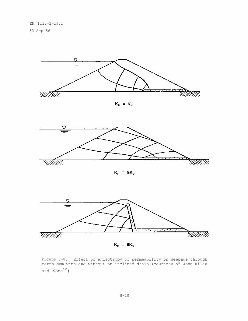
EM 1110-2-1901
30 Sep 86
KH = KV
KH = 9KV
KH = 9KV
Figure 8-8. Effect of anisotropy of permeability on seepage throughearth dam with and without an inclined drain (courtesy of John Wiley
and Sons155)
8-10
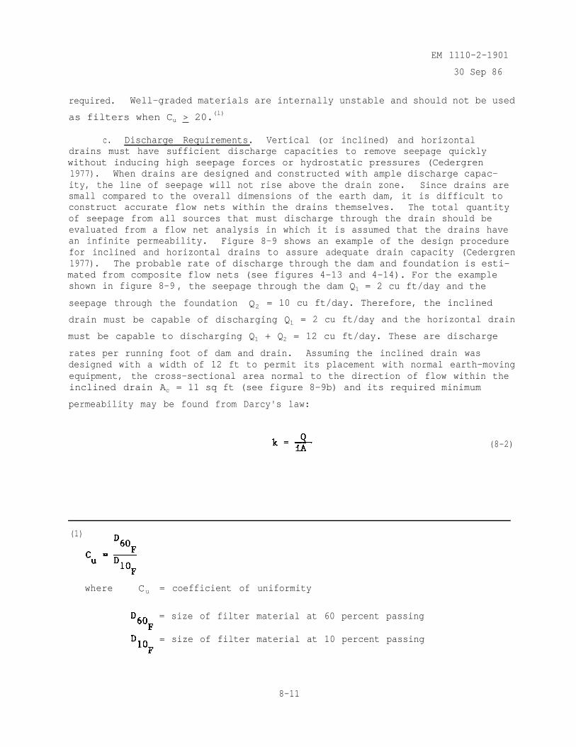
EM 1110-2-1901
30 Sep 86
required. Well-graded materials are internally unstable and should not be used
as filters when Cu > 20.(l)
c. Discharge Requirements. Vertical (or inclined) and horizontaldrains must have sufficient discharge capacities to remove seepage quicklywithout inducing high seepage forces or hydrostatic pressures (Cedergren1977). When drains are designed and constructed with ample discharge capac-ity, the line of seepage will not rise above the drain zone. Since drains aresmall compared to the overall dimensions of the earth dam, it is difficult toconstruct accurate flow nets within the drains themselves. The total quantityof seepage from all sources that must discharge through the drain should beevaluated from a flow net analysis in which it is assumed that the drains havean infinite permeability. Figure 8-9 shows an example of the design procedurefor inclined and horizontal drains to assure adequate drain capacity (Cedergren1977). The probable rate of discharge through the dam and foundation is esti-mated from composite flow nets (see figures 4-13 and 4-14). For the exampleshown in figure 8-9 , the seepage through the dam Q1 = 2 cu ft/day and the
seepage through the foundation Q2 = 10 cu ft/day. Therefore, the inclined
drain must be capable of discharging Q1 = 2 cu ft/day and the horizontal drain
must be capable to discharging Q1 + Q2 = 12 cu ft/day. These are discharge
rates per running foot of dam and drain. Assuming the inclined drain wasdesigned with a width of 12 ft to permit its placement with normal earth-movingequipment, the cross-sectional area normal to the direction of flow within theinclined drain Ac = 11 sq ft (see figure 8-9b) and its required minimum
permeability may be found from Darcy's law:
(8-2)
(1)
where Cu = coefficient of uniformity
= size of filter material at 60 percent passing
= size of filter material at 10 percent passing
8-11
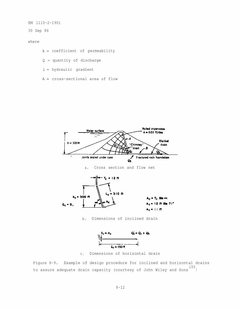
EM 1110-2-1901
30 Sep 86
where
k = coefficient of permeability
Q = quantity of discharge
i = hydraulic gradient
A = cross-sectional area of flow
a. Cross section and flow net
b. Dimensions of inclined drain
c. Dimensions of horizontal drain
Figure 8-9. Example of design procedure for inclined and horizontal drains
to assure adequate drain capacity (courtesy of John Wiley and Sons155
)
8-12
EM 1110-2-1901
30 Sep 86
Substituting for Q , 1 , and A
(8-3)
Every filter must be permeable enough to have a reasonable reserve for higherthan expected flows. The filter should have a minimum permeability afterplacement and compaction of at least 20 times that calculated theoretically.Therefore, the required permeability for the inclined drain is
(8-4)
Clean, washed concrete sand is usually about this permeable. As previouslystated,ft/day.
the horizontal drain must be capable of discharging Q1 + Q2 = 12 cuSince the drain is to be designed so that the line of seepage does
not rise above the drain zone, the allowable maximum head in the horizontaldrain can be no greater than its height. The required minimum permeabilityfrom Darcy's law is
(8-5)
Substituting Ab = hb (width is one running foot of dam and drain)
8-13
EM 1110-2-1901
30 Sep 86
(8-6)
To design the horizontal drain, select a drain height and calculate therequired minimum permeability. Apply a factor of safety of 20 to the calcu-lated permeability and select a drain material from available aggregates.Select a drain height of 4 ft.
The required permeability for design is
This permeability could be obtained by screened fine gravel (3/8-in. to 1/2-in.size) which has a permeability of about 30,000 ft/day or 10.6 cm/sec
8-14
EM 1110-2-1901
30 Sep 86
(Cedergren 1977). Seepage in coarse aggregate is likely to be turbulent and areduction factor should be applied to the permeability. The hydraulic gradientin the horizontal drain is
From figure 8-10, for screened fine gravel (3/8-in. to 1/2-in. size) with1 = 0.007 the reduction factor for permeability is 0.9.
(8-7)
(8-8)
The permeability of the screened fine gravel (3/8-in. to 1/2-in. size) reducedfor turbulence is greater than the required permeability for design:
Therefore, it should be adequate when properly placed and compacted to conductseepage water through the horizontal drain. The screened fine gravel (3/8-in.to 1/2-in. size) will be protected top and bottom with a 1-ft-thick cleanwashed concrete sand filter. Since the seepage from the foundation must flowacross the fine filter to enter the coarse drainage layer, the fine filter mustbe permeable enough to allow the water to enter the coarse drainage layerfreely under only a small hydraulic gradient (0.5 or less). Assume an averagehydraulic gradient of 0.5 across the fine filter layer and Q2 = 10 cu ft/day
for the amount of water that will enter the first (left) 200 ft of the drain.From Darcy's law the required minimum permeability of the fine filter is (seeequation 8-2)
k = 0.1 ft/day
8-15
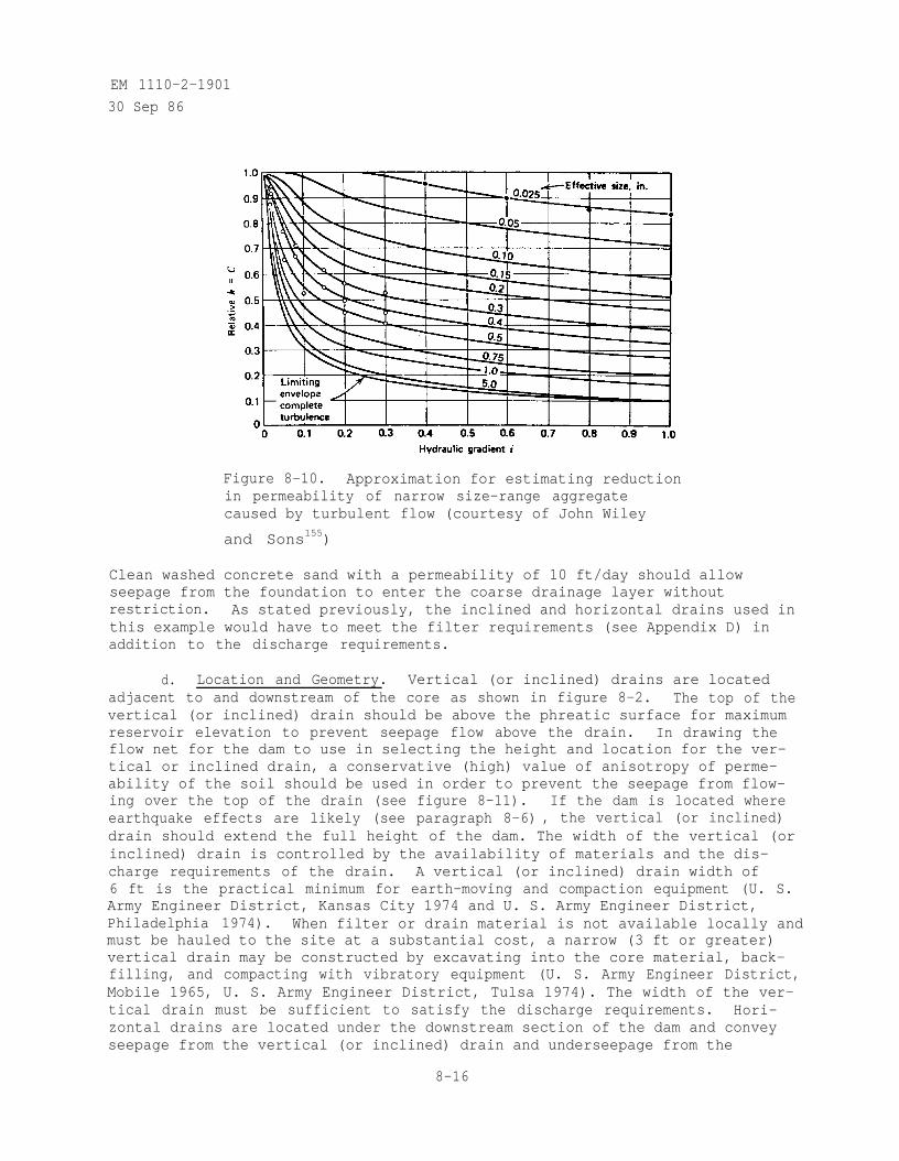
EM 1110-2-1901
30 Sep 86
Figure 8-10. Approximation for estimating reductionin permeability of narrow size-range aggregatecaused by turbulent flow (courtesy of John Wiley
and Sons155)
Clean washed concrete sand with a permeability of 10 ft/day should allowseepage from the foundation to enter the coarse drainage layer withoutrestriction. As stated previously, the inclined and horizontal drains used inthis example would have to meet the filter requirements (see Appendix D) inaddition to the discharge requirements.
d. Location and Geometry. Vertical (or inclined) drains are locatedadjacent to and downstream of the core as shown in figure 8-2. The top of thevertical (or inclined) drain should be above the phreatic surface for maximumreservoir elevation to prevent seepage flow above the drain. In drawing theflow net for the dam to use in selecting the height and location for the ver-tical or inclined drain, a conservative (high) value of anisotropy of perme-ability of the soil should be used in order to prevent the seepage from flow-ing over the top of the drain (see figure 8-11). If the dam is located whereearthquake effects are likely (see paragraph 8-6) , the vertical (or inclined)drain should extend the full height of the dam. The width of the vertical (orinclined) drain is controlled by the availability of materials and the dis-charge requirements of the drain. A vertical (or inclined) drain width of6 ft is the practical minimum for earth-moving and compaction equipment (U. S.Army Engineer District, Kansas City 1974 and U. S. Army Engineer District,Philadelphia 1974). When filter or drain material is not available locally andmust be hauled to the site at a substantial cost, a narrow (3 ft or greater)vertical drain may be constructed by excavating into the core material, back-filling, and compacting with vibratory equipment (U. S. Army Engineer District,Mobile 1965, U. S. Army Engineer District, Tulsa 1974). The width of the ver-tical drain must be sufficient to satisfy the discharge requirements. Hori-zontal drains are located under the downstream section of the dam and conveyseepage from the vertical (or inclined) drain and underseepage from the
8-16
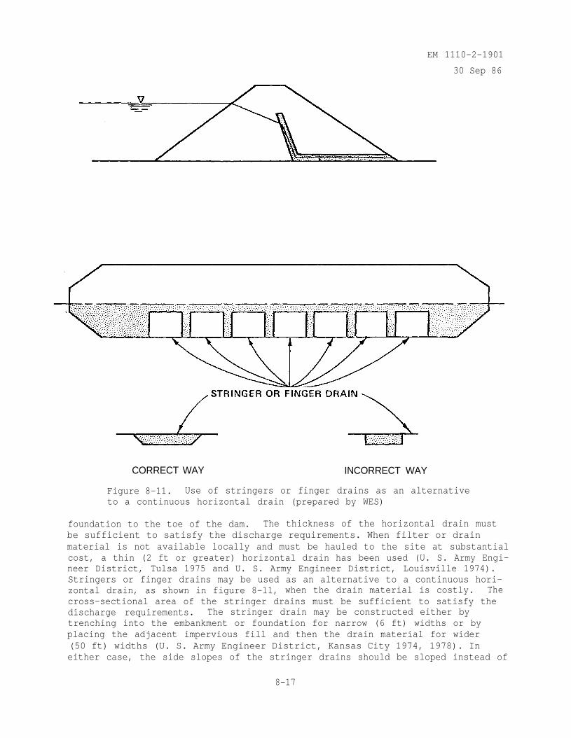
EM 1110-2-1901
30 Sep 86
CORRECT WAY INCORRECT WAY
Figure 8-11. Use of stringers or finger drains as an alternativeto a continuous horizontal drain (prepared by WES)
foundation to the toe of the dam. The thickness of the horizontal drain mustbe sufficient to satisfy the discharge requirements. When filter or drainmaterial is not available locally and must be hauled to the site at substantialcost, a thin (2 ft or greater) horizontal drain has been used (U. S. Army Engi-neer District, Tulsa 1975 and U. S. Army Engineer District, Louisville 1974).Stringers or finger drains may be used as an alternative to a continuous hori-zontal drain, as shown in figure 8-11, when the drain material is costly. Thecross-sectional area of the stringer drains must be sufficient to satisfy thedischarge requirements. The stringer drain may be constructed either bytrenching into the embankment or foundation for narrow (6 ft) widths or byplacing the adjacent impervious fill and then the drain material for wider(50 ft) widths (U. S. Army Engineer District, Kansas City 1974, 1978). Ineither case, the side slopes of the stringer drains should be sloped instead of
8-17
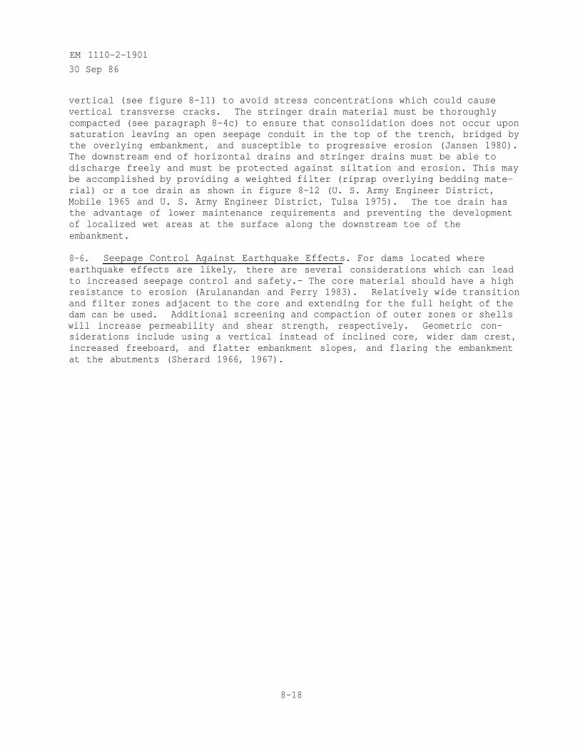
EM 1110-2-1901
30 Sep 86
vertical (see figure 8-11) to avoid stress concentrations which could causevertical transverse cracks. The stringer drain material must be thoroughlycompacted (see paragraph 8-4c) to ensure that consolidation does not occur uponsaturation leaving an open seepage conduit in the top of the trench, bridged bythe overlying embankment, and susceptible to progressive erosion (Jansen 1980).The downstream end of horizontal drains and stringer drains must be able todischarge freely and must be protected against siltation and erosion. This maybe accomplished by providing a weighted filter (riprap overlying bedding mate-rial) or a toe drain as shown in figure 8-12 (U. S. Army Engineer District,Mobile 1965 and U. S. Army Engineer District, Tulsa 1975). The toe drain hasthe advantage of lower maintenance requirements and preventing the developmentof localized wet areas at the surface along the downstream toe of theembankment.
8-6. Seepage Control Against Earthquake Effects. For dams located whereearthquake effects are likely, there are several considerations which can leadto increased seepage control and safety.- The core material should have a highresistance to erosion (Arulanandan and Perry 1983). Relatively wide transitionand filter zones adjacent to the core and extending for the full height of thedam can be used. Additional screening and compaction of outer zones or shellswill increase permeability and shear strength, respectively. Geometric con-siderations include using a vertical instead of inclined core, wider dam crest,increased freeboard, and flatter embankment slopes, and flaring the embankmentat the abutments (Sherard 1966, 1967).
8-18
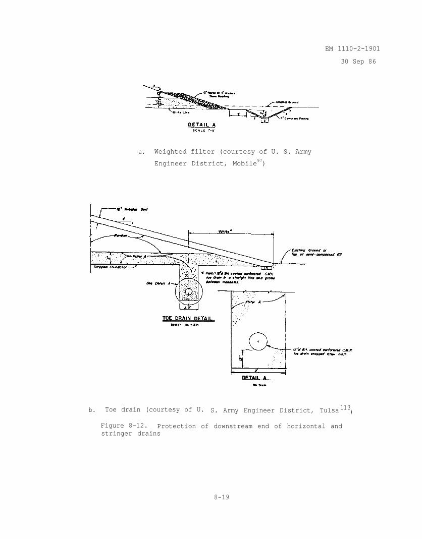
EM 1110-2-1901
30 Sep 86
a. Weighted filter (courtesy of U. S. Army
Engineer District, Mobile97)
b. Toe drain (courtesy of U. S. Army Engineer District, Tulsa 113)
Figure 8-12. Protection of downstream end of horizontal andstringer drains
8-19
EM 1110-2-1901
30 Sep 86
CHAPTER 9SEEPAGE CONTROL IN EARTH FOUNDATIONS
9-1. General. All dams on earth foundations are subject to underseepage.Seepage control in earth foundations is necessary to prevent excessive upliftpressures and piping through the foundation (seepage control in earth abut-ments is given in Chapter 10). The purpose of the project, i.e., long-termstorage, flood control, hydropower, etc., may impose limitations on the allow-able quantity of seepage. Generally, siltation of the reservoir with timewill tend to diminish underseepage (U. S. Army Engineer Division, Ohio River1945). Conversely, the use of some underseepage control methods such as reliefwells and toe drains may increase the quantity of underseepage (Sowers 1962).
9-2. Selection of Method for Seepage Control. The methods for control ofunderseepage in dam foundations are horizontal drains, cutoffs (compacted back-
fill trenches, slurry walls, concrete walls, and steel sheetpiling (1)), up-stream impervious blankets, downstream seepage berms, toe drains, and reliefwells. To select an underseepage control method for a particular dam andfoundation, the relative merits and efficiency of different methods should beevaluated by means of flow nets or approximate methods as described inChapter 4 and Appendix B, respectively. As shown in table 9-1, the changes inthe quantity of underseepage, factor of safety against uplift, and uplift pres-sures at various locations should be determined for each particular dam andfoundation. Since the anisotropy ratio of the foundation has a significantinfluence on the results of the underseepage analysis, this parameter should be
varied as appropriate to cover the possible range of
expected field conditions.
9-3. Horizontal Drains. As mentioned previously in Chapter 8, horizontaldrains are used to control seepage through the embankment and to preventexcessive uplift pressures in the foundation. As shown in figure 9-1, the useof the horizontal drain significantly reduces the uplift pressure in the foun-dation under the downstream portion of the dam. The computation of upliftpressure was illustrated previously in figure 4-15. Figure 9-1 also showsthat the horizontal drain increases the quantity of seepage under the dam.
9-4. Cutoffs.
a. Complete Versus Partial Cutoff. When the dam foundation consists ofa relatively thick deposit of pervious alluvium, the designer must decidewhether to make a complete cutoff (compacted backfill trench, slurry trench,or concrete wall) or allow a certain amount of underseepage to occur undercontrolled conditions (partial cutoff , upstream impervious blanket, downstreamseepage berm, toe trench drain, or relief walls), In some cases, where thealluvium is not very deep or the water is very valuable, it may be obvious
(1) Steel sheetpiling is not recommended to prevent underseepage but is usedto confine the foundation soil and prevent piping.
9-1
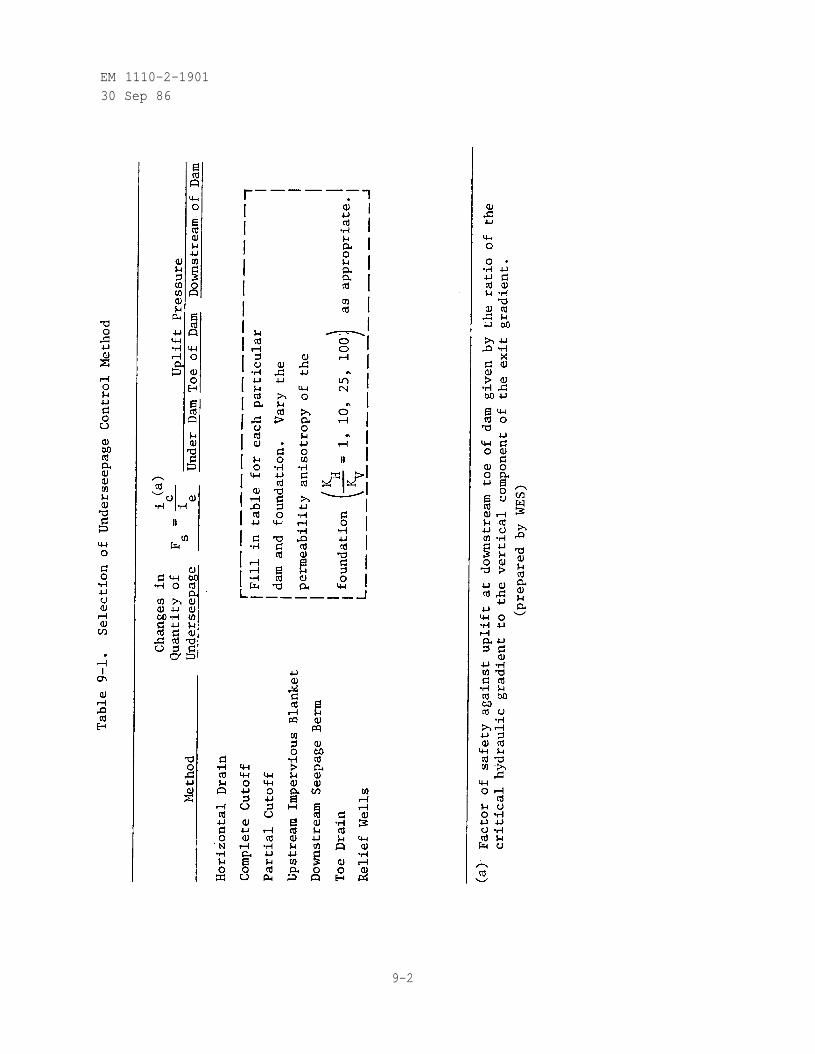
EM 1110-2-190130 Sep 86
9-2
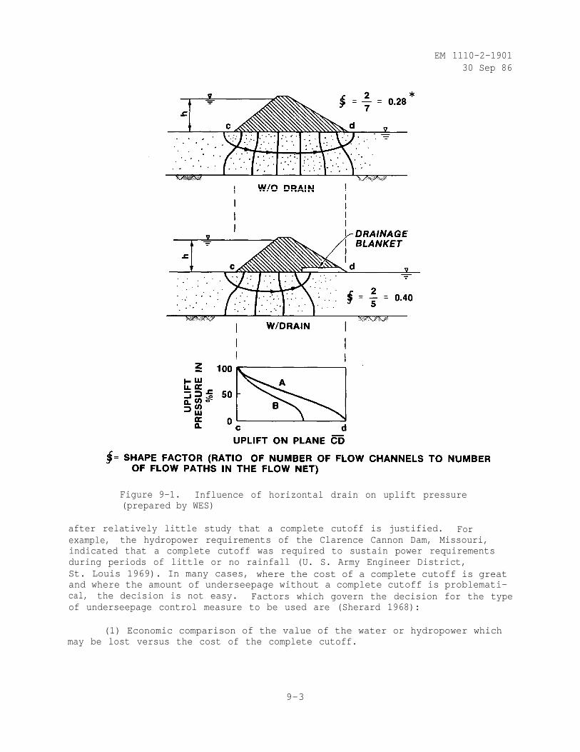
EM 1110-2-190130 Sep 86
Figure 9-1. Influence of horizontal drain on uplift pressure(prepared by WES)
after relatively little study that a complete cutoff is justified. Forexample, the hydropower requirements of the Clarence Cannon Dam, Missouri,indicated that a complete cutoff was required to sustain power requirementsduring periods of little or no rainfall (U. S. Army Engineer District,St. Louis 1969). In many cases, where the cost of a complete cutoff is greatand where the amount of underseepage without a complete cutoff is problemati-cal, the decision is not easy. Factors which govern the decision for the typeof underseepage control measure to be used are (Sherard 1968):
(1) Economic comparison of the value of the water or hydropower whichmay be lost versus the cost of the complete cutoff.
9-3
EM 1110-2-190130 Sep 86
(2) The resistance of the foundation alluvium with respect to potentialprogressive backward erosion of leaks or piping. If the foundation containslayers of fine sand or cohesionless silt, and particularly if these soils areexposed on the surface of the valley floor or walls, a complete cutoff is moredesirable than if the foundation is basically gravelly (or even coarse sand).If a large leak develops in a relatively coarse alluvium, in all probabilityit will be safe against progressive backward erosion, but even a small con-centrated leak emerging below the dam in fine cohesionless soils can behazardous.
(3) If the tailwater conditions are such that ponds of water existdownstream of the dam so that underseepage would emerge underwater and couldnot be observed, it is desirable to be more conservative in evaluating theneed for a complete seepage cutoff.
(4) The amount of silt and clay sized particles in suspension in theriver water which contributes to siltation of the reservoir with time andtends to diminish underseepage.
Theory and model tests indicate that it is necessary for a cutoff to penetratea homogeneous isotropic foundation at least 95 percent of the full depth beforethere is any appreciable reduction in seepage beneath an earth embankment asshown in figure 9-2 (Telling, Menzies, and Coulthord 1978; and Mansur andPerret 1949). The effectiveness of the partial cutoff in reducing the quan-tity of underseepage decreases as the ratio of the width of the dam to thedepth of penetration of the cutoff increases (see figure 9-2). Partial cut-offs are effective only when they extend down into an intermediate stratum oflower permeability. This stratum must be continuous across the valley founda-tion to ensure that three-dimensional seepage around a discontinuous stratumdoes not negate the effectiveness of the partial cutoff.
b. Efficiency of Cutoffs. The effectiveness of the cutoff is assessedeither in terms of the flow efficiency (Casagrande 1961)
(9-1)
where
E q = flow efficiency of cutoff
Qo = rate of underseepage without cutoff
Q = rate of underseepage with cutoff
or head efficiency (Lane and Wohlt 1961)
(9-2)
9-4
EM 1110-2-1901
30 Sep 86
where
EH = head efficiency of cutoff
h = head loss between points immediately upstream and downstream of thecutoff wall at its junction with the base of the dam
H = head loss across the dam
The head efficiency is more widely used because the field performance may beestablished from piezometric data taken during construction, before and duringinitial filling of the reservoir, and subsequently as frequently as necessaryto determine changes that are occurring and to assess their implications withrespect to safety of the dam, as described in Chapter 13. The flow efficiencymay only be approximated since the rate of underseepage without the cutoffcannot be directly established and since it is difficult to measure the rateof underseepage with the cutoff because, except for special cases, only partof the underseepage discharges at the ground surface immediately downstream ofthe dam (Telling, Menzies, and Simons 1978a and Marsal and Resendiz 1971). Theflow efficiency of a compacted backfill partial cutoff in a foundation ofpermeable soils of moderate thickness overlying an impervious rock is shown infigure 9-3. This figure also illustrates the high seepage gradients that occuralong the base of the cutoff and on its downstream face in both the foundationand embankment zones. Suitable filters must be provided to prevent piping ofsoil at faces A-B-C in figure 9-3a and 9-3b (Cedergren 1977 and Klohn 1979).As shown in figure 9-4, a partial cutoff in a homogeneous isotropic foundationwill lower the line of seepage in the downstream embankment somewhat but exitgradients at the downstream toe (as reflected by the distance between theequipotential lines) are reduced only slightly (Cedergren 1973). When the
pervious foundation is cut off by a compacted backfill or slurry trench, (1) therate of underseepage may be estimated by (Ambraseys 1963 and Marsal andResendiz 1971)
where
Qo3
= rate of underseepage in m /set per running meter of dam
K O = permeability of the foundation in m/sec
(9-3)
(1) This approach neglects the contribution of the filter cake that forms onthe trench walls to the overall slurry trench permeability. When thepermeability of the backfill placed in the trench is high, the overallslurry trench permeability will be controlled by the filter cake(D'Appolonia 1980).
9-5
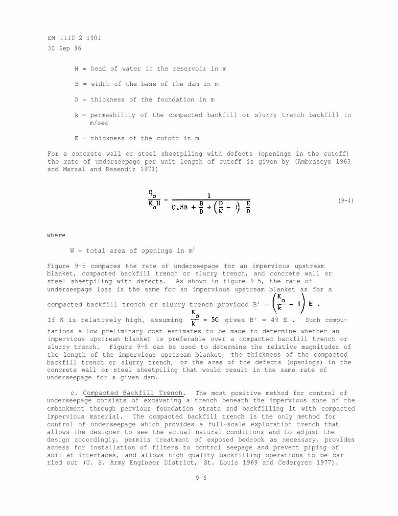
EM 1110-2-1901
30 Sep 86
H = head of water in the reservoir in m
B = width of the base of the dam in m
D = thickness of the foundation in m
k = permeability of the compacted backfill or slurry trench backfill inm/sec
E = thickness of the cutoff in m
For a concrete wall or steel sheetpiling with defects (openings in the cutoff)the rate of underseepage per unit length of cutoff is given by (Ambraseys 1963and Marsal and Resendiz 1971)
(9-4)
where
W = total area of openings in m2
Figure 9-5 compares the rate of underseepage for an impervious upstreamblanket, compacted backfill trench or slurry trench, and concrete wall orsteel sheetpiling with defects. As shown in figure 9-5, the rate ofunderseepage loss is the same for an impervious upstream blanket as for a
compacted backfill trench or slurry trench provided B' =
If K is relatively high, assuming gives B' = 49 E . Such compu-
tations allow preliminary cost estimates to be made to determine whether animpervious upstream blanket is preferable over a compacted backfill trench orslurry trench. Figure 9-6 can be used to determine the relative magnitudes ofthe length of the impervious upstream blanket, the thickness of the compactedbackfill trench or slurry trench, or the area of the defects (openings) in theconcrete wall or steel sheetpiling that would result in the same rate ofunderseepage for a given dam.
c. Compacted Backfill Trench. The most positive method for control ofunderseepage consists of excavating a trench beneath the impervious zone of theembankment through pervious foundation strata and backfilling it with compactedimpervious material. The compacted backfill trench is the only method forcontrol of underseepage which provides a full-scale exploration trench thatallows the designer to see the actual natural conditions and to adjust thedesign accordingly, permits treatment of exposed bedrock as necessary, providesaccess for installation of filters to control seepage and prevent piping ofsoil at interfaces, and allows high quality backfilling operations to be car-ried out (U. S. Army Engineer District, St. Louis 1969 and Cedergren 1977).
9-6
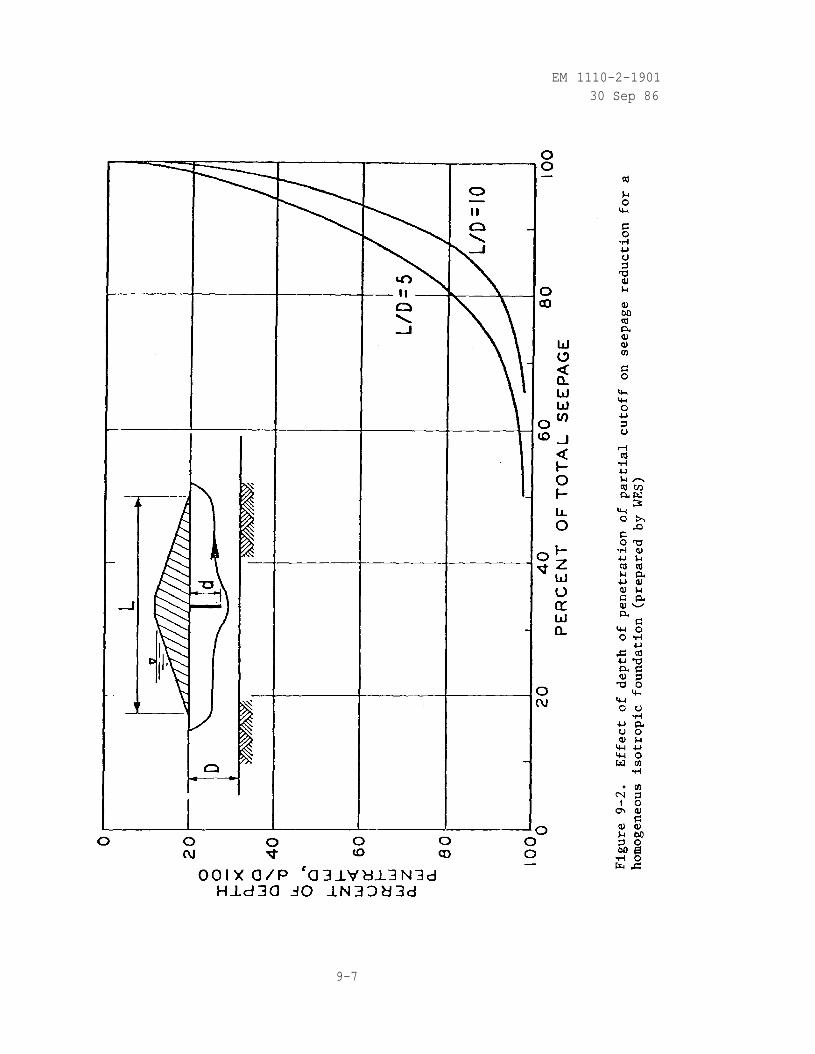
EM 1110-2-190130 Sep 86
9-7
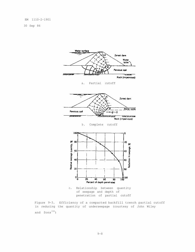
EM 1110-2-1901
30 Sep 86
a. Partial cutoff
b. Complete cutoff
c. Relationship between quantityof seepage and depth ofpenetration of partial cutoff
Figure 9-3. Efficiency of a compacted backfill trench partial cutoffin reducing the quantity of underseepage (courtesy of John Wiley
and Sons155)
9-8
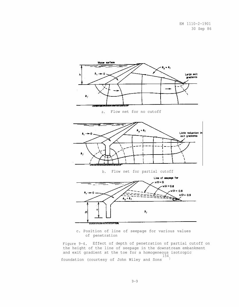
EM 1110-2-190130 Sep 86
a. Flow net for no cutoff
b. Flow net for partial cutoff
c. Position of line of seepage for various valuesof penetration
Figure 9-4. Effect of depth of penetration of partial cutoff onthe height of the line of seepage in the downstream embankmentand exit gradient at the toe for a homogeneous isotropic
foundation (courtesy of John Wiley and Sons154
)
9-9
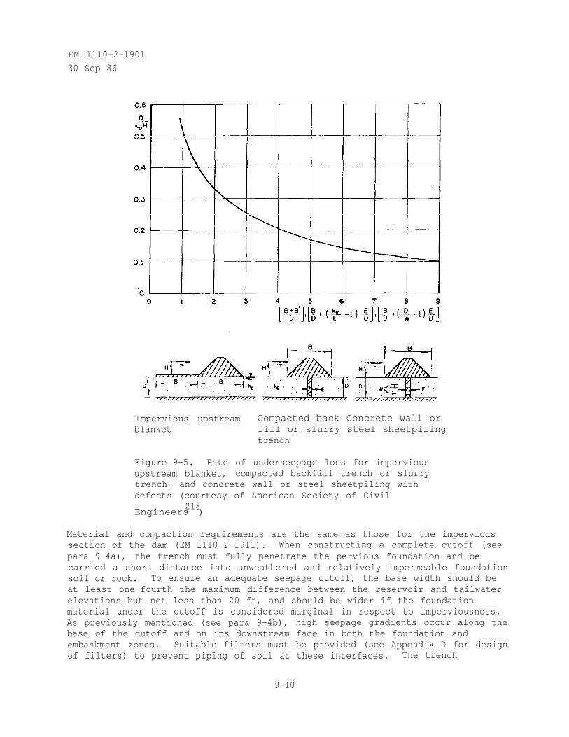
EM 1110-2-1901
30 Sep 86
Impervious upstream Compacted back Concrete wall orblanket fill or slurry steel sheetpiling
trench
Figure 9-5. Rate of underseepage loss for imperviousupstream blanket, compacted backfill trench or slurrytrench, and concrete wall or steel sheetpiling withdefects (courtesy of American Society of Civil
218Engineers )
Material and compaction requirements are the same as those for the impervioussection of the dam (EM 1110-2-1911). When constructing a complete cutoff (seepara 9-4a), the trench must fully penetrate the pervious foundation and becarried a short distance into unweathered and relatively impermeable foundationsoil or rock. To ensure an adequate seepage cutoff, the base width should beat least one-fourth the maximum difference between the reservoir and tailwaterelevations but not less than 20 ft, and should be wider if the foundationmaterial under the cutoff is considered marginal in respect to imperviousness.As previously mentioned (see para 9-4b), high seepage gradients occur along thebase of the cutoff and on its downstream face in both the foundation andembankment zones. Suitable filters must be provided (see Appendix D for designof filters) to prevent piping of soil at these interfaces. The trench
9-10
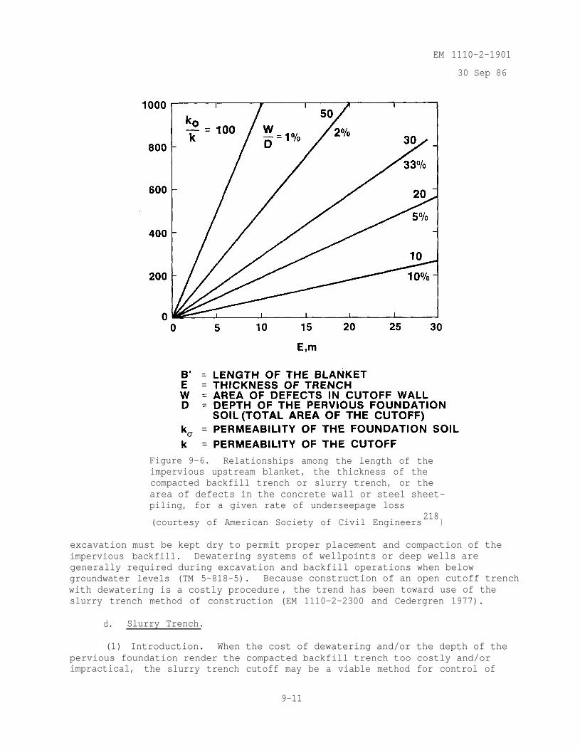
EM 1110-2-1901
30 Sep 86
Figure 9-6. Relationships among the length of theimpervious upstream blanket, the thickness of thecompacted backfill trench or slurry trench, or thearea of defects in the concrete wall or steel sheet-piling, for a given rate of underseepage loss
(courtesy of American Society of Civil Engineers218
)
excavation must be kept dry to permit proper placement and compaction of theimpervious backfill. Dewatering systems of wellpoints or deep wells aregenerally required during excavation and backfill operations when belowgroundwater levels (TM 5-818-5). Because construction of an open cutoff trenchwith dewatering is a costly procedure , the trend has been toward use of theslurry trench method of construction (EM 1110-2-2300 and Cedergren 1977).
d. Slurry Trench.
(1) Introduction. When the cost of dewatering and/or the depth of thepervious foundation render the compacted backfill trench too costly and/orimpractical, the slurry trench cutoff may be a viable method for control of
9-11
EM 1110-2-1901
30 Sep 86
underseepage. Using this method, a trench is excavated through the perviousfoundation using a sodium bentonite clay (or Attapulgite clay in saline water)and water slurry to support the sides. The slurry-filled trench is backfilledby displacing the slurry with a backfill material that contains enough fines(material passing the No. 200 sieve) to make the cutoff relatively imperviousbut sufficient coarse particles to minimize settlement of the trench forming asoil-bentonite cutoff (sometimes called American method). Alternatively,cement may be introduced into the slurry-filled trench which is left to set orharden forming a cement-bentonite cutoff (sometimes called a grouted diaphragmwall or Coulis wall or European method). The slurry trench cutoff is notrecommended when boulders, talus blocks on buried slopes, or open jointed rockexist in the foundation due to difficulties in excavating through the rock andslurry loss through the open joints. Where a slurry trench is relied upon forseepage control, the initial filling of the reservoir must be controlled andpiezometers located both upstream and downstream of the cutoff must be read todetermine if the slurry trench is performing as planned. If the cutoff isineffective, remedial seepage control measures (see Chapter 12) must beinstalled prior to further raising of the reservoir pool (KM 1110-2-2300).
(a) History of Use. The first use of the slurry trench method of con-struction was by the U. S. Army Engineer District, Memphis, in September 1945,to form a partial cutoff along the Mississippi River levee on the Arkansasside of the river just below Memphis, Tennessee (Clay 1976 and Kramer 1946).The idea for the project probably evolved from the use at that time of puddleclay trench cutoffs combined with the use of drilling mud for advancingborings. A paddle wheel mixing device was constructed for making slurry fromnative clays. Trenches were dug to a 20-ft depth using a trenching machine andto a 35-ft depth using a dragline with a 100-ft boom and 2-cu-yd bucket.Backfill was mixed in windrows at the site from hauled-in clay gravel andnative materials and pushed into the trench by a bulldozer when the length ofthe trench was equal to about twice the trench depth. BG Hans Kramer foresawthe use of the slurry trench method for the construction of cutoffs for earthdams. It is amazing that after 38 years, the technique is still about the sameas it was when first developed by the Memphis District. A soil-bentonitecutoff was constructed under the Kennewick Levee adjacent to the Columbia Riveras part of the McNary Dam Project in Washington by the Walla Walla District in1952 (Jones 1961). The first application of a soil-bentonite slurry trenchcutoff for control of underseepage at a major earth dam was at Wanapum Dam onthe Columbia River in Washington in 1959 (La Russo 1963). Subsequently, soil-bentonite cutoffs have been used for control of underseepage at a number ofdams as shown in table 9-2. The cement-bentonite slurry trench cutoff wasfirst used to tie into the abutment zones at the Razaza Dam on the EuphratesRiver in Iraq in 1969 (Soletanche 1969). Subsequently, cement-bentonite cut-offs were installed as remedial seepage control measures through the embank-ment and foundation of four existing dams in Mexico from 1970 to 1972(Soletanche 1970, 1971, 1971-1972, 1972). As shown in table 2, the firstcement-bentonite cutoff in the United States was constructed at the TildenTailings Project to store tailings from the Tilden Mine in Michigan in 1976(Meier and Rettberg 1978). The first cement-bentonite cutoff constructed at adam on a river retaining a reservoir in the United States was completed in1978 at the Elgo Dam (formerly the San Carlos Dam) in Arizona (Anonymous 1978and Miller and Salzman 1980).
9-12
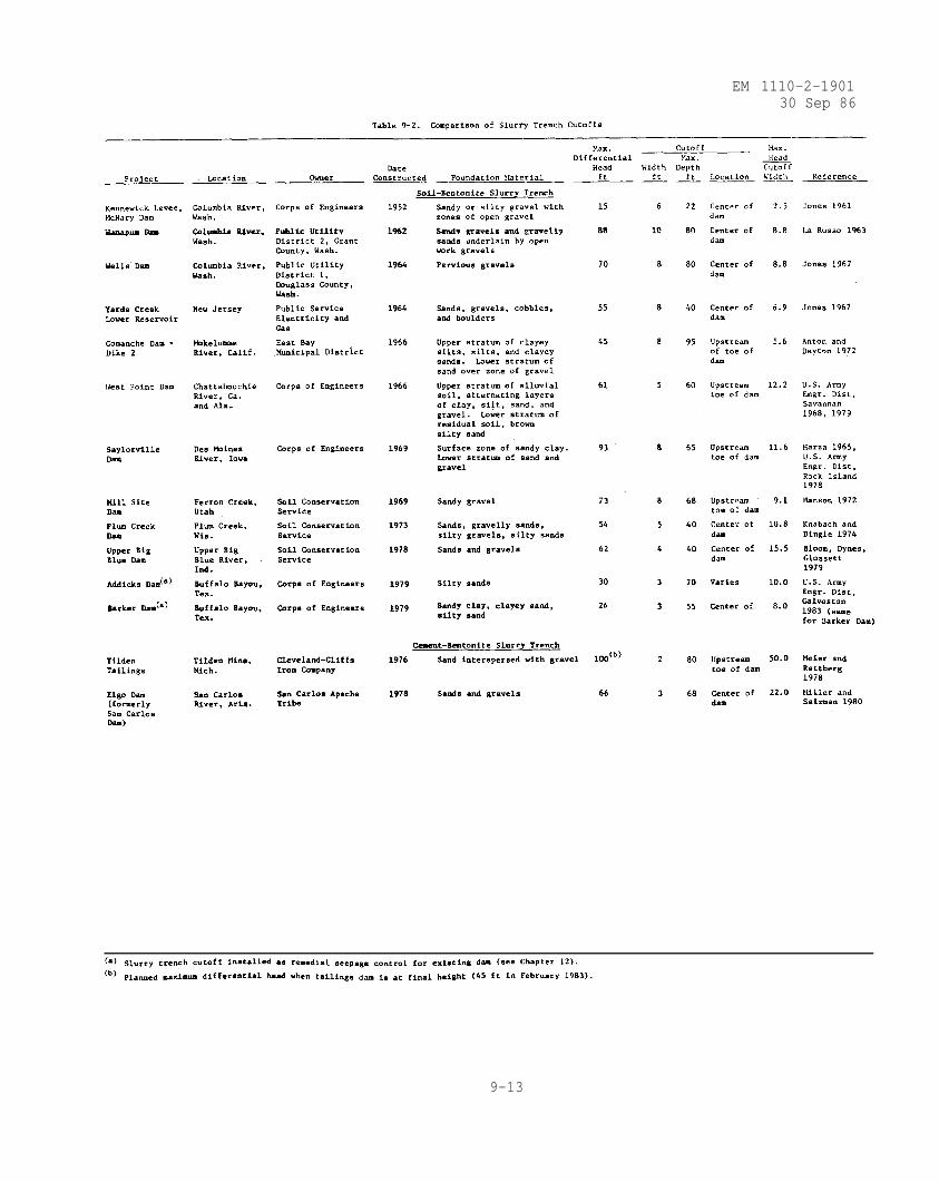
EM 1110-2-190130 Sep 86
9-13
EM 1110-2-1901
30 Sep 86
(b) Patents. The soil-bentonite slurry trench cutoff was covered byUnited States Patent No. 2,757,514 dated August 7, 1956, "Method of Forming anImpermeable Wall in the Terrain," in the name of Harold T. Wyatt. This patentexpired in 1973. The cement-bentonite slurry trench cutoff is covered byUnited States Patent No. 3,759,044 dated September 18, 1973, "Method of EarthWall Construction Using Cementitious Bentonite Mud," in the name of ClaudeCaron and Jean Hurtado, both of France, assignor to Soletanche, Paris, France.
(c) Comparison of Soil-Bentonite and Cement-Bentonite Slurry TrenchCutoffs. A comparison of soil-bentonite and cement-bentonite slurry trenchcutoffs is given in table 9-3. The soil-bentonite slurry trench cutoff isgenerally the most economical if the cost of backfill is not prohibitive. Fordeep cutoffs where the foundation is prone to failure during excavation, thecement-bentonite slurry trench cutoff is more applicable.
(d) Location of Cutoff. Normally, the slurry trench should be locatedunder or near the upstream toe of the dam (EM 1110-2-2300). An upstreamlocation provides access for future treatment provided the reservoir could bedrawn down and facilitates stage construction by permitting placement of adownstream shell followed by an upstream core tied into the slurry trench. Forstability analysis, a soil-bentonite slurry trench cutoff should be consideredto have zero shear strength and exert only a hydrostatic force to resistfailure of the embankment (U. S. Army Engineer District, Savannah 1968). Ifthe slurry trench is located under a central core, consolidation of the slurrytrench backfill combined with arching of the core material immediately abovethe slurry trench may result in the opening of a cavity under the dam withpossible leakage along the contact. If a central location for the slurrytrench is dictated by other factors, some possible benefits are obtained byflaring the top of the trench to provide a transition between the cutoff andthe core. Also, the slurry trench can be constructed and allowed to settlebefore placement of the embankment (Jones 1967 and Jansen 1968). When thegroundwater table is located some distance beneath the ground surface, it isusually more economical to excavate a conventional open trench with stable sideslopes with the trench bottom a few feet above the highest level of groundwater expected during the construction period, as was done at West Point Dam,Alabama and Georgia (U. S. Army Engineer District, Savannah 1968). The bottomof the open trench provides a working level from which the slurry trench may beconstructed. Also, this prevents the problem of significant amounts of slurrybeing lost into the excavated trench above the ground-water table. If theground-water table is located near the ground surface, compacted imperviousfill should be placed in order to raise the level of the slurry trench tomaintain the level of slurry in the trench a sufficient distance above theground-water level (Jones 1967).
(e) Stability of the Trench. In cohesionless soils the penetration ofthe slurry into the wall of the slurry trench excavation forms a relativelyimpervious filter cake on which the hydrostatic pressure of the slurry canact. The depth of penetration ranges from 1 to 3 in. in sand, 3 to 6 in. insand and gravel, and up to 12 in. in gravel, depending on the gradation. Themain stabilizing force supporting the slurry trench excavation is the hydro-static pressure exerted on the trench walls. For a slurry trench excavated ina homogeneous clay, remaining open only for a few days to permit placement of
9-14
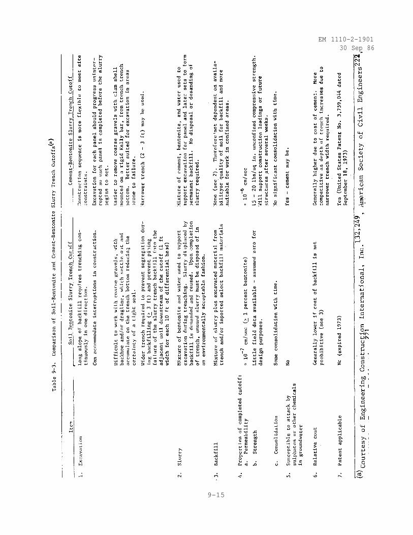
EM 1110-2-190130 Sep 86
9-15
EM 1110-2-1901
30 Sep 86
backfill material, the factor of safety against instability is (Nash and Jones1963)
(9-5)
where
F = factor of safety
Cu = undrained cohesion
H = depth of the trench
= unit weight of the soil
= unit weight of the slurry
For a slurry trench excavated in dry cohesionless soil (Nash and Jones 1963)
where angle of internal friction.
For a slurry trench excavated in a saturated cohesionless soil with theground-water table and slurry level in the excavation both at the groundsurface (Nash and Jones 1963)
where
= effective unit weight of the soil
= effective unit weight of the slurry
= effective angle of internal friction
(9-6)
(9-7)
For arbitrary levels of ground water and slurry in cohesionless soil, as shownin figure 9-7a, a slightly conservative (neglects arching effect of short
9-16
EM 1110-2-190130 Sep 86
trenches and stabilization of the soil adjacent to the trench face due toslurry penetration and gelation) estimate of the slurry density required toensure stability of the trench is (Morgenstern and Amir-Tahmasseb 1965)
(9-8)
where
n = defined in figure 9-7a
= unit weight of the slurry
= unit weight of water
= unit weight of the soil
= angle of inclination of the wedge of soil at the point of slipping,in practice assumed to be equal to 45" +
effective angle of internal friction
m = defined in figure 9-7a
Equation 9-6 may be solved by use of the nomograph shown in figure 9-7b(Duguid et al. 1971).
(2) Slurry. The slurry has three basic functions in slurry trenchconstruction (Ryan 1977):
• To hold the trench open and maintain a stable excavation.
• To be fluid enough to permit passage of the excavating equip-ment and to allow placement of the backfill (for the cement-bentonite slurrytrench, there is no backfill).
• To form a filter cake to enhance the low permeability of thecompleted trench.
(a) Materials. As a general rule sodium montmorillonite in powder form(Wyoming-type bentonite) is used for slurry trench construction. However,when salt water is present Attapulgite clay is used to avoid flocculation(Spooner et al. 1982). Specifications for both bentonite and Attapulgite aregiven by the American Petroleum Institute (American Petroleum Institute 1981).Each shipment of bentonite or Attapulgite should be checked for compliance withthe specifications. At Saylorville Dam, Iowa, changes in slurry propertieswere traced to lower quality bentonite which was mined from different beds(U. S. Army Engineer District, Rock Island 19788). No chemically treated
9-17
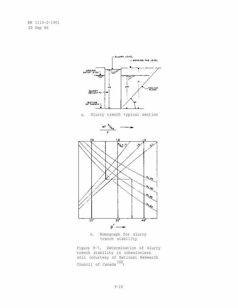
EM 1110-2-190130 Sep 86
a. Slurry trench typical section
b. Nomograph for slurrytrench stability
Figure 9-7. Determination of slurrytrench stability in cohesionlesssoil (courtesy of National Research
Council of Canada168
)
9-18
EM 1110-2-190130 Sep 86
bentonite should be used for slurry trench construction. The pH of the waterused for mixing with the bentonite should equal 7.0 ± 1.0. Water hardnessshould not exceed 50 ppm (parts per million). Total dissolved solids shouldnot exceed 500 ppm. The amount of oil, organics, or other deleterious sub-stances should be limited to no more than 50 ppm each (Stanley Consultants,Inc., and Woodward-Clyde Consultants 1977). If the use of poor quality watercannot be avoided, it will require more bentonite and longer mixing times toachieve the desired properties.
(b) Mixing. The methods used to prepare the hentonite slurry vary withproject size and layout. Always add the bentonite to the water, never thewater to the bentonite. For small jobs the batch system is used wherespecific quantities of water and bentonite are placed in a tank and mixed athigh speeds with a circulationpump or paddle mixer and the slurry is dis-charged into the trench. Mixing is usually complete in a matter of minutesfor the 2- to 5-cu-yd batch produced by this method. The most commonly usedmethod is the flash or Venturi mixer and circulation ponds which is welladapted for bulk handling of large slurry volumes. A flash mixer introducesdry bentonite into a turbulent water jet which discharges into a low speedcirculation pond. When Marsh Funnel viscosity readings stabilize, the slurryis stored in a second pond prior to using the trench (Spooner et al. 1982 andD'Appolonia 1980).
(c) Properties. Tests of bentonite quality must be conducted for eachrail car or truck load delivered. The minimum acceptable viscosity of a slurrymade with the bentonite is 40 seconds Marsh funnel viscosity at 65° F. Thefresh slurry shall have a minimum Marsh funnel viscosity of 40 seconds at 65° Fand a pH of from 7 to 10, a bentonite content of from 3 to 7 percent by dryweight (depending on the grade of bentonite), a unit weight of from 1.0 to1.04 g/cm3 (about 65 lb/ft3), and the filtrate or water loss shall not begreater than 20 at 100 lb/in.2 x cm3 in 30 minutes (Spooner et al. 1982 andU. S. Army Engineer District, Savannah 1968). The slurry in the trench shouldbe sampled at least twice daily with samples taken from the top of the trenchand at 10-ft vertical, 50-ft horizontal intervals along the trench center line.During all stages of construction the minimum acceptable viscosity of theslurry shall be 40 seconds Marsh funnel viscosity at 65° F. The minimumin-trench slurry unit weight is based upon trench stability considerations (seeEquation 9-8 and Figure 9-7). The maximum in-trench slurry density is 85/ft3
to avoid buildup of sediment beyond the slurry capacity to hold it in suspen-sion in the trench during excavation (Clough 1978).
(d) Quality Control Testing. In order to mix and maintain a properslurry to hold the trench open during excavation and form a filter cake forthe soil-bentonite slurry trench, quality control testing must be performed.The property, frequency, standard (if any), and specified value for slurriesand their components are given in table 9-4. The quality of the mixing waterused can influence the slurry trench characteristics. If the specific valuesfor mixing water quality are not met, the bentonite will flocculate and settleout and not form the filter cake on the sides of the trench. Poor qualitymixing water will increase the set time for cement-bentonite slurry trenchcutoffs. The bentonite is tested to be sure it will have the minimum viscos-ity required to keep the soil in suspension. The slurry is tested both after
9-19
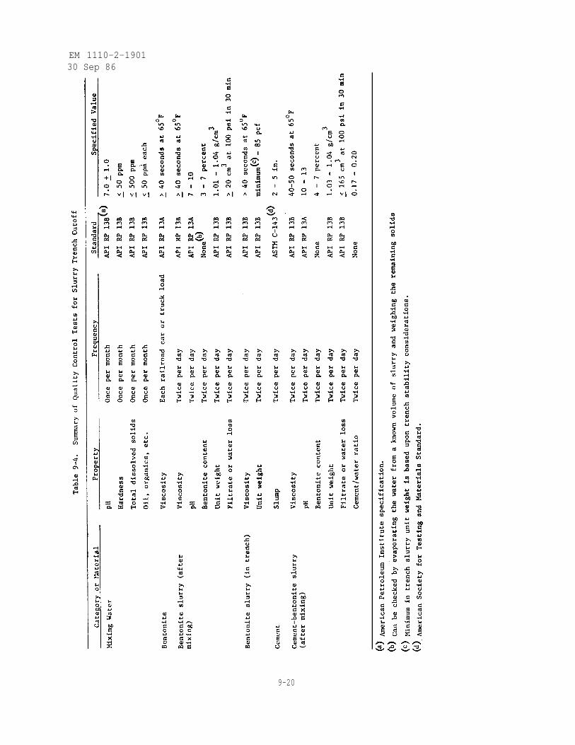
EM 1110-2-190130 Sep 86
9-20
EM 1110-2-190130 Sep 86
mixing and in the trench to determine that it is dense enough to stabilize thetrench, but not so dense as to cause the backfill to settle too loosely, andthat it has sufficient viscosity to maintain cuttings in suspension (StanleyConsultants, Inc., and Woodward-Clyde Consultants 1976).
(3) Excavation, Mixing, and Backfilling.
(a) Excavation. The preferred method of trench excavation depends uponthe required depth of the slurry trench cutoff, the nature of the subsurfacematerials, and access to the trench at the ground surface. It is important toensure that the equipment used can maintain a continuous excavation line tothe total depth required. At depths less than about 50 ft, backhoes are gen-erally the most rapid and least costly excavation method. Modified backhoeswith an extended dipper stick, modified engine, and counter-weighted frame canexcavate to about 80 ft deep. Draglines with weighted (> 10,000 lb) buckets,which have been used in the depth range 60 to 80 ft, have been replaced by moreefficient extended backhoes. The clamshell bucket can excavate to depths inexcess of 150 ft. The clamshell may be mechanically operated attached to acrane or hydraulically operated attached to a Kelly bar. On larger jobs, thebackhoe may be used to excavate the first 50 ft followed by a clamshell bucketto excavate the primary and secondary panels to the impervious zone. Regard-less of the equipment used, it should be capable of excavating a trench of thedesired width in a single pass in order to obtain a fairly consistent trenchwidth. The bucket used should be nonperforated to allow retention and removalof sand particles from the trench. The continuity of the trench is tested bypassing the bucket or clamshell of the excavating tool vertically and horizon-tally along each segment of the trench before it is backfilled. Whateverexcavation method is used, it is important that good communications are main-tained with the operator of the excavation equipment since abnormalities inthe trench excavation are usually noticed first by the equipment operator(D'Appolonia 1980; Spooner et al. 1982; Bloom, Dynes, and Glossett 1979; CaseInternational Company 1982; and Winter 1978). Soil-bentonite slurry trenchcutoffs are excavated in a continuous trench as shown in figure 9-8a, whilecement-bentonite slurry trench cutoffs are excavated in a continuous trench orin short sections or panels as shown in figure 9-8b. The cement-bentoniteslurry begins to harden within 2 to 3 hours after mixing. Alternate panelsare excavated under a cement-bentonite slurry and then allowed to partiallyset. Intervening panels are excavated also under a cement-bentonite slurryand a portion of the initial panel ends are removed to ensure continuitybetween adjacent panels. Construction delays can cause problems in setup ofcement-bentonite slurry trench cutoffs because continued agitation of thecement-bentonite slurry (more than 24 hours) reduces the ability of the cementto set (Spooner et al. 1982).
(b) Bottom Treatment. The aquiclude used for the slurry wall founda-tions should be continuous, and relatively free of fractures and other perviouszones. The cutoff wall should extend a minimum of 2 ft into clay (or 1 ft intorock) to prevent weathered zones, desiccation cracks, or other geologicalfeatures from permitting seepage under the cutoff (Spooner 1982). As thetrench is excavated, heavier soil particles such as sand and gravel fall to thebottom of the trench. The amount of sand accumulation on the trench bottomdepends upon the coarseness of the strata being excavated as well as the
9-21
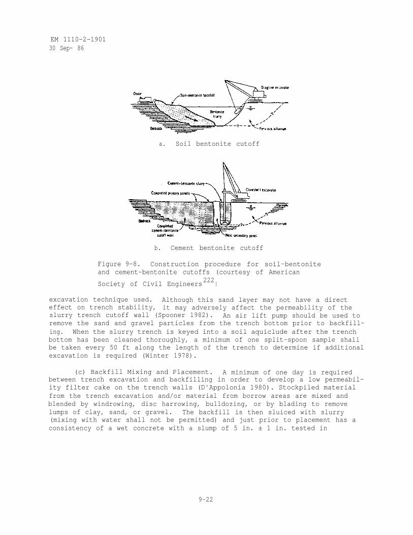
EM 1110-2-190130 Sep- 86
a. Soil bentonite cutoff
b. Cement bentonite cutoff
Figure 9-8. Construction procedure for soil-bentoniteand cement-bentonite cutoffs (courtesy of American
Society of Civil Engineers222 )
excavation technique used. Although this sand layer may not have a directeffect on trench stability, it may adversely affect the permeability of theslurry trench cutoff wall (Spooner 1982). An air lift pump should be used toremove the sand and gravel particles from the trench bottom prior to backfill-ing. When the slurry trench is keyed into a soil aquiclude after the trenchbottom has been cleaned thoroughly, a minimum of one split-spoon sample shallbe taken every 50 ft along the length of the trench to determine if additionalexcavation is required (Winter 1978).
(c) Backfill Mixing and Placement. A minimum of one day is requiredbetween trench excavation and backfilling in order to develop a low permeabil-ity filter cake on the trench walls (D'Appolonia 1980). Stockpiled materialfrom the trench excavation and/or material from borrow areas are mixed andblended by windrowing, disc harrowing, bulldozing, or by blading to removelumps of clay, sand, or gravel. The backfill is then sluiced with slurry(mixing with water shall not be permitted) and just prior to placement has aconsistency of a wet concrete with a slump of 5 in. ± 1 in. tested in
9-22
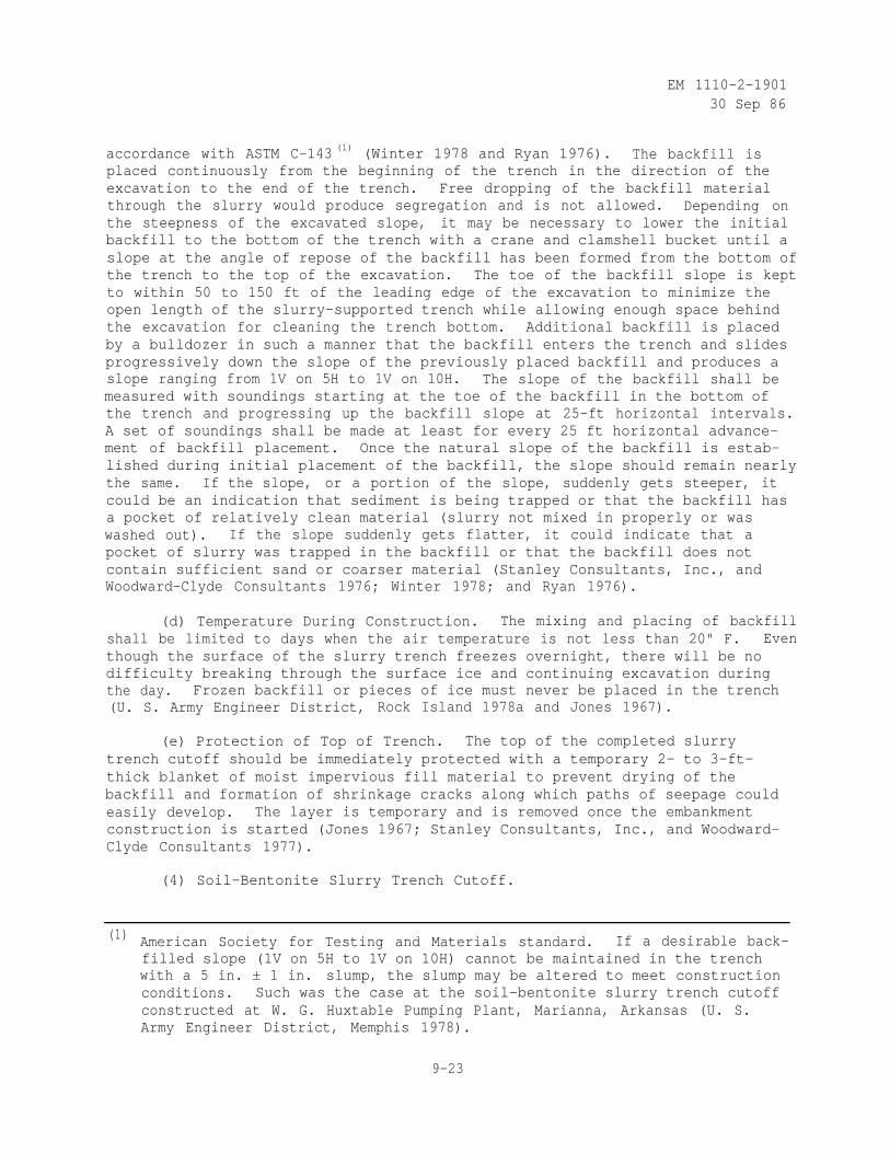
EM 1110-2-190130 Sep 86
accordance with ASTM C-143 (1) (Winter 1978 and Ryan 1976). The backfill isplaced continuously from the beginning of the trench in the direction of theexcavation to the end of the trench. Free dropping of the backfill materialthrough the slurry would produce segregation and is not allowed. Depending onthe steepness of the excavated slope, it may be necessary to lower the initialbackfill to the bottom of the trench with a crane and clamshell bucket until aslope at the angle of repose of the backfill has been formed from the bottom ofthe trench to the top of the excavation. The toe of the backfill slope is keptto within 50 to 150 ft of the leading edge of the excavation to minimize theopen length of the slurry-supported trench while allowing enough space behindthe excavation for cleaning the trench bottom. Additional backfill is placedby a bulldozer in such a manner that the backfill enters the trench and slidesprogressively down the slope of the previously placed backfill and produces aslope ranging from 1V on 5H to 1V on 10H. The slope of the backfill shall bemeasured with soundings starting at the toe of the backfill in the bottom ofthe trench and progressing up the backfill slope at 25-ft horizontal intervals.A set of soundings shall be made at least for every 25 ft horizontal advance-ment of backfill placement. Once the natural slope of the backfill is estab-lished during initial placement of the backfill, the slope should remain nearlythe same. If the slope, or a portion of the slope, suddenly gets steeper, itcould be an indication that sediment is being trapped or that the backfill hasa pocket of relatively clean material (slurry not mixed in properly or waswashed out). If the slope suddenly gets flatter, it could indicate that apocket of slurry was trapped in the backfill or that the backfill does notcontain sufficient sand or coarser material (Stanley Consultants, Inc., andWoodward-Clyde Consultants 1976; Winter 1978; and Ryan 1976).
(d) Temperature During Construction. The mixing and placing of backfillshall be limited to days when the air temperature is not less than 20" F. Eventhough the surface of the slurry trench freezes overnight, there will be nodifficulty breaking through the surface ice and continuing excavation duringthe day. Frozen backfill or pieces of ice must never be placed in the trench(U. S. Army Engineer District, Rock Island 1978a and Jones 1967).
(e) Protection of Top of Trench. The top of the completed slurrytrench cutoff should be immediately protected with a temporary 2- to 3-ft-thick blanket of moist impervious fill material to prevent drying of thebackfill and formation of shrinkage cracks along which paths of seepage couldeasily develop. The layer is temporary and is removed once the embankmentconstruction is started (Jones 1967; Stanley Consultants, Inc., and Woodward-Clyde Consultants 1977).
(4) Soil-Bentonite Slurry Trench Cutoff.
(1) American Society for Testing and Materials standard. If a desirable back-filled slope (1V on 5H to 1V on 10H) cannot be maintained in the trenchwith a 5 in. ± 1 in. slump, the slump may be altered to meet constructionconditions. Such was the case at the soil-bentonite slurry trench cutoffconstructed at W. G. Huxtable Pumping Plant, Marianna, Arkansas (U. S.Army Engineer District, Memphis 1978).
9-23
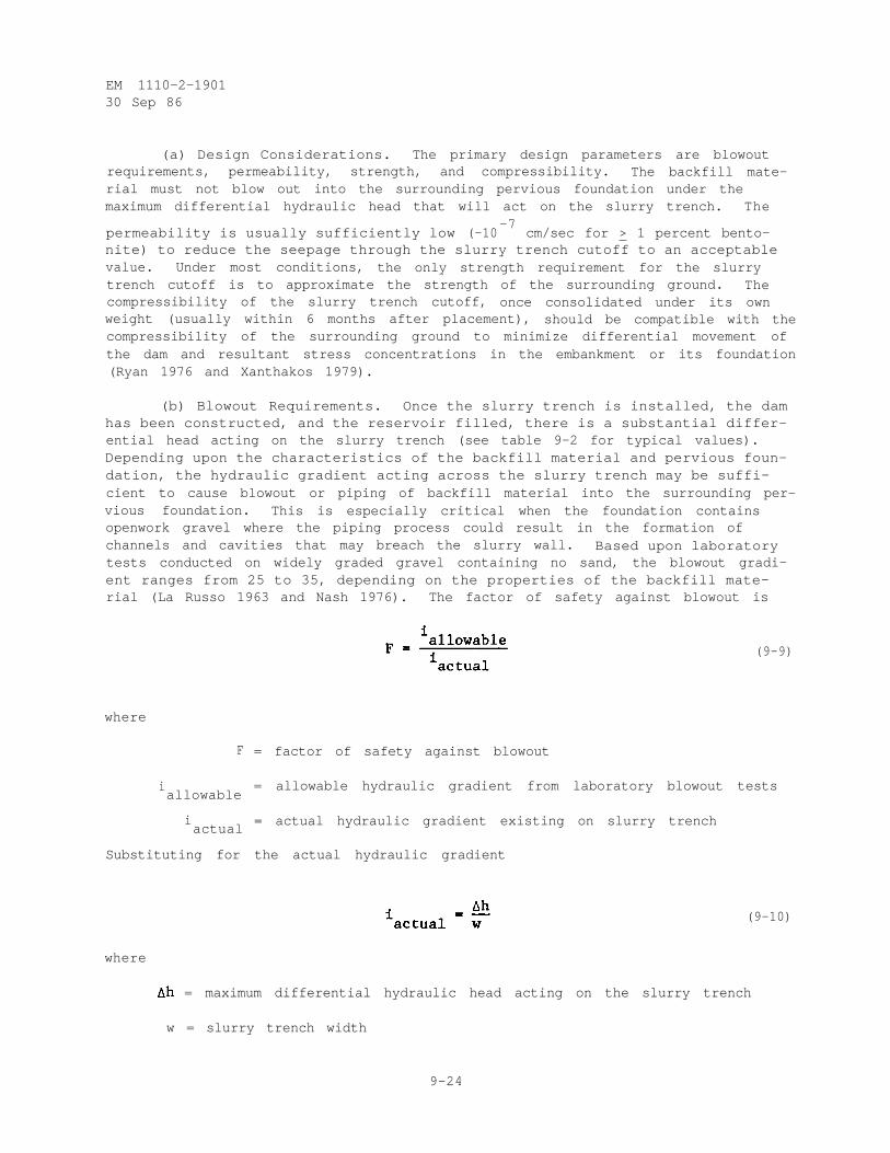
EM 1110-2-190130 Sep 86
(a) Design Considerations. The primary design parameters are blowoutrequirements, permeability, strength, and compressibility. The backfill mate-rial must not blow out into the surrounding pervious foundation under themaximum differential hydraulic head that will act on the slurry trench. The
permeability is usually sufficiently low (-10-7
cm/sec for > 1 percent bento-nite) to reduce the seepage through the slurry trench cutoff to an acceptablevalue. Under most conditions, the only strength requirement for the slurrytrench cutoff is to approximate the strength of the surrounding ground. Thecompressibility of the slurry trench cutoff, once consolidated under its ownweight (usually within 6 months after placement), should be compatible with thecompressibility of the surrounding ground to minimize differential movement ofthe dam and resultant stress concentrations in the embankment or its foundation(Ryan 1976 and Xanthakos 1979).
(b) Blowout Requirements. Once the slurry trench is installed, the damhas been constructed, and the reservoir filled, there is a substantial differ-ential head acting on the slurry trench (see table 9-2 for typical values).Depending upon the characteristics of the backfill material and pervious foun-dation, the hydraulic gradient acting across the slurry trench may be suffi-cient to cause blowout or piping of backfill material into the surrounding per-vious foundation. This is especially critical when the foundation containsopenwork gravel where the piping process could result in the formation ofchannels and cavities that may breach the slurry wall. Based upon laboratorytests conducted on widely graded gravel containing no sand, the blowout gradi-ent ranges from 25 to 35, depending on the properties of the backfill mate-rial (La Russo 1963 and Nash 1976). The factor of safety against blowout is
(9-9)
where
F = factor of safety against blowout
iallowable
= allowable hydraulic gradient from laboratory blowout tests
iactual
= actual hydraulic gradient existing on slurry trench
Substituting for the actual hydraulic gradient
(9-10)
where
= maximum differential hydraulic head acting on the slurry trench
w = slurry trench width
9-24
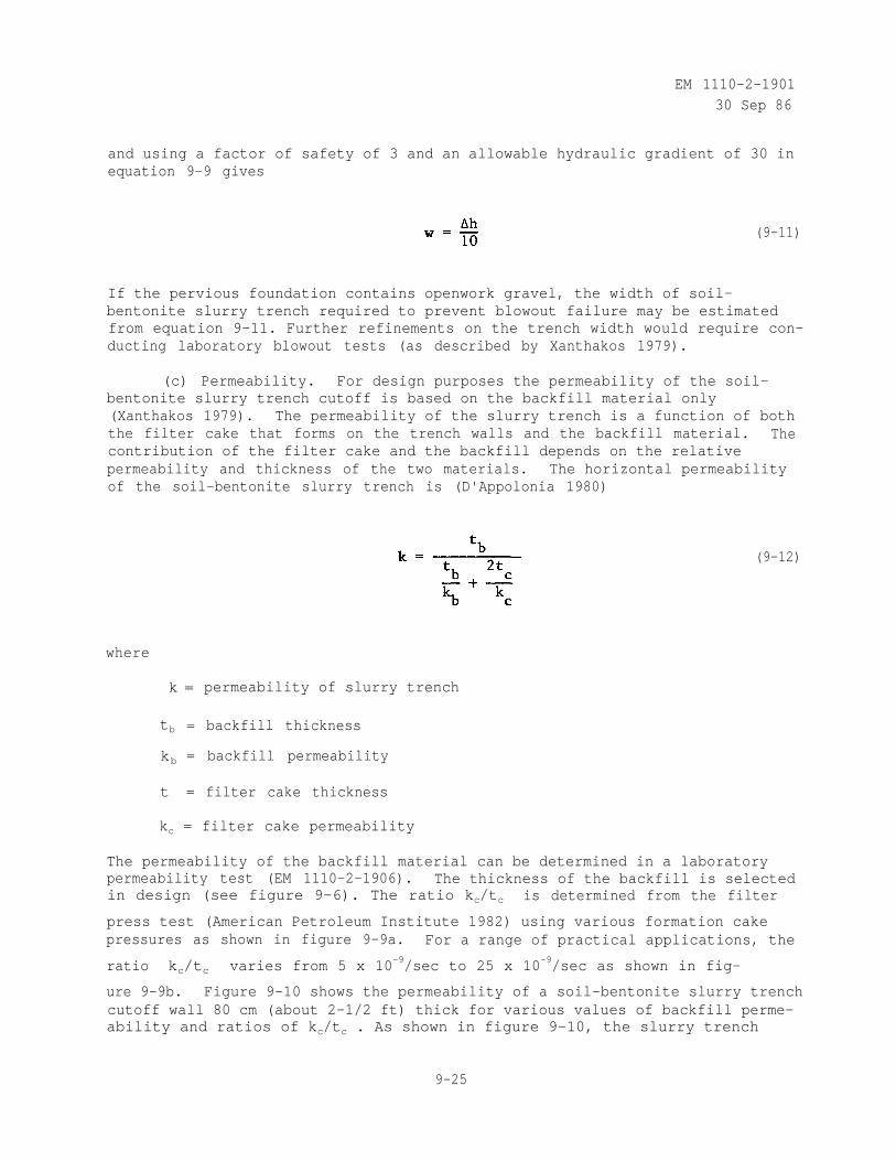
EM 1110-2-190130 Sep 86
and using a factor of safety of 3 and an allowable hydraulic gradient of 30 inequation 9-9 gives
(9-11)
If the pervious foundation contains openwork gravel, the width of soil-bentonite slurry trench required to prevent blowout failure may be estimatedfrom equation 9-11. Further refinements on the trench width would require con-ducting laboratory blowout tests (as described by Xanthakos 1979).
(c) Permeability. For design purposes the permeability of the soil-bentonite slurry trench cutoff is based on the backfill material only(Xanthakos 1979). The permeability of the slurry trench is a function of boththe filter cake that forms on the trench walls and the backfill material. Thecontribution of the filter cake and the backfill depends on the relativepermeability and thickness of the two materials. The horizontal permeabilityof the soil-bentonite slurry trench is (D'Appolonia 1980)
(9-12)
where
k = permeability of slurry trench
tb = backfill thickness
kb = backfill permeability
t = filter cake thickness
kc = filter cake permeability
The permeability of the backfill material can be determined in a laboratorypermeability test (EM 1110-2-1906). The thickness of the backfill is selectedin design (see figure 9-6). The ratio kc/tc is determined from the filter
press test (American Petroleum Institute 1982) using various formation cakepressures as shown in figure 9-9a. For a range of practical applications, the
ratio kc/tc varies from 5 x 10⁻⁹/sec to 25 x 10-9/sec as shown in fig-
ure 9-9b. Figure 9-10 shows the permeability of a soil-bentonite slurry trenchcutoff wall 80 cm (about 2-1/2 ft) thick for various values of backfill perme-ability and ratios of kc/tc . As shown in figure 9-10, the slurry trench
9-25
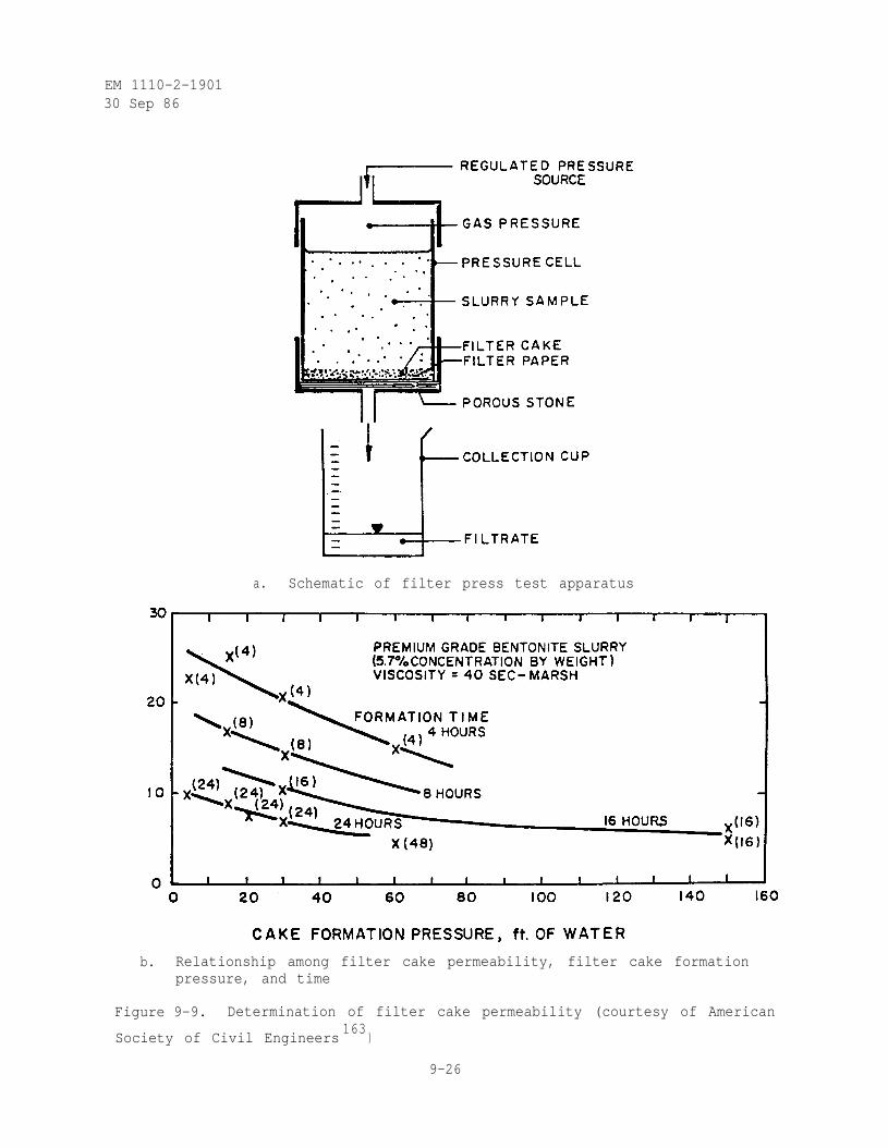
EM 1110-2-190130 Sep 86
a. Schematic of filter press test apparatus
b. Relationship among filter cake permeability, filter cake formationpressure, and time
Figure 9-9. Determination of filter cake permeability (courtesy of American
Society of Civil Engineers163
)
9-26
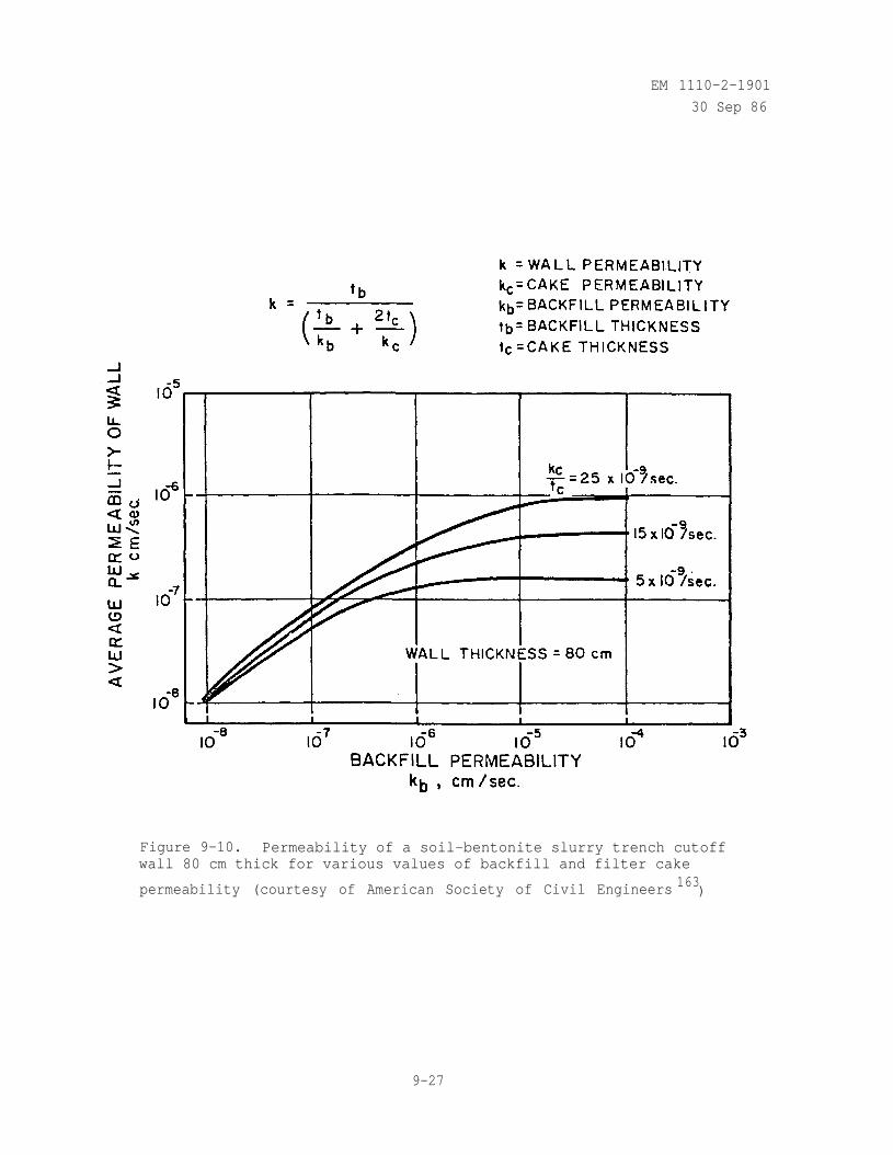
EM 1110-2-1901
30 Sep 86
Figure 9-10. Permeability of a soil-bentonite slurry trench cutoffwall 80 cm thick for various values of backfill and filter cake
permeability (courtesy of American Society of Civil Engineers 163)
9-27
EM 1110-2-190130 Sep 86
permeability is controlled by the backfill when the backfill permeability islow and by the filter cake when the backfill permeability is high. Also, the
slurry trench permeability has an upper limit of about 10-6
cm/sec even forvery permeable backfill due to the thin low permeability filter cake(D'Appolonia 1980).
(d) Shear Strength. Soil-bentonite slurry trench cutoffs are difficultto sample because of their soft nature and very little data are available onthe shear strength of soil-bentonite slurry trench backfill material. Fordesign purposes, in conducting the stability analysis of the embankment andfoundation, the shear strength of the backfill material is assumed, to be zero.However, the shear strength of the backfill material does increase with timedue to consolidation and thixotropy. At time of placement, the backfill mate-rial will stand on a slope ranging from 1V on 5H to 1V on 10H. This improvesto about 1V on 2H with time (Ryan 1976 and D'Appolonia 1980). The results ofshear strength tests (see table 9-5) on undisturbed samples taken from thesoil-bentonite slurry trench at Saylorville Dam, Iowa, show that the undrainedshear strength of the slurry backfill about a year after placement was 0.10 to0.12 tons/sq ft (U. S. Army Engineer District, Rock Island 1978b).
(e) Compressibility. The compressibility of the soil-bentonite slurrytrench backfill material depends primarily on the percentage of granularparticles in the gradation as shown in figure 9-11. Low permeability and lowcompressibility are contradictory requirements because the plastic finesrequired for low permeability result in higher compressibility. Relativelylow compressibility results when there is sufficient granular material in thebackfill to allow grain-to-grain contact between the granular particles(D'Appolonia 1980).
(f) Mix Design. The gradation of the backfill for the soil-bentoniteslurry trench is selected by conducting permeability, shear strength, and com-pressibility tests on a range of materials including soil to be excavated fromthe trench. Such a procedure was followed in the mix design for the backfillof the soil-bentonite slurry trench installed for remedial seepage control atAddicks Dam, Texas (U. S. Army Engineer District, Galveston 1977c). The allow-able range set on the gradation of the backfill should produce a material whichcontains enough fines to reduce the seepage through the slurry trench cutoff toan acceptable level and sufficient coarse particles to approximate the strengthand compressibility of the surrounding ground. If sufficient fines are notpresent in material excavated from the trench, borrow sources should be identi-fied or alternatively a higher bentonite content specified for the backfill.If sufficient coarse particles are not present in material excavated from thetrench, approved sources should be identified for obtaining natural sound,hard, durable sand and gravel. Crushed limestone, dolomite, or other crushedcalcareous materials should not be used. The maximum particle size of thegravel shall be 3 in. and the material should be well graded.
(5) Cement-Bentonite Slurry Trench Cutoff.
9-28
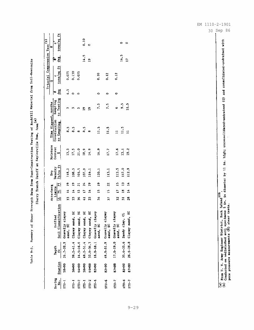
EM 1110
30
-2-1901Sep 86
9-29
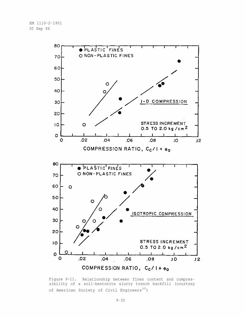
EM 1110-2-190130 Sep 86
Figure 9-11. Relationship between fines content and compres-sibility of a soil-bentonite slurry trench backfill (courtesy
of American Society of Civil Engineers163)
9-30
EM 1110-2-1901
30 Sep 86
(a) General. If backfill for the slurry trench is not available or isprohibitive in cost or if the cutoff is deep and the foundation is prone tofailure during excavation, the cement-bentonite slurry trench cutoff may bemore applicable (see table 9-3).
(b) Design Considerations. The primary design parameters are continu-ity, set time, resistance to hydraulic pressure, permeability, shear strength,and compressibility.
(c) Continuity. When cement-bentonite slurry trench cutoffs are con-structed in panels rather than in a continuous trench, there is a possibilityfor unexcavated portions of the trench to remain between the panels. To pre-vent this the clamshell bucket is moved both vertically and horizontallythroughout each slot at the completion of slot excavation. Also, when theconnecting area between the initial and subsequent panels is excavated, a por-tion of the adjacent set panels is removed to ensure that all intervening soilhas been excavated (Spooner et al. 1982).
(d) Set Time. The set time is important because of the constructiontechnique employed. After the cement-bentonite slurry in the first set ofpanels has set, the areas between them can be excavated. A normal cement-bentonite mixture begins to set after a few hours and has a consistency simi-lar to lard after 12 hours. The second day the cement-bentonite slurry can bewalked on and final set is normally taken at 90 days (Ryan 1977).
(e) Resistance to Hydraulic Pressure. Once the slurry trench has beencompleted, the embankment constructed, and the reservoir filled, there is asubstantial differential head acting on the slurry trench (see table 9-2 fortypical values). The time between completion of the slurry trench and reser-voir filling is generally sufficiently long (> 90 days) to allow the cement-bentonite slurry trench to develop its final set. The resistance of thecement-bentonite material to withstand gradients comparable to those whichwill exist in the field should be tested in the laboratory by subjectingintact specimens which have developed full set to hydraulic pressure andmeasuring the increase (if any) of permeability with time (Spooner et al. 1982and Jefferis 1981).
(f) Permeability. Although there is some buildup of concentration nearthe sides of the cement-bentonite slurry trench, the cement-bentonite does notform a low permeability cake. The permeability of the slurry trench is afunction of the concentrations of cement, bentonite, sand, and gravel (sus-pended during the excavation process) in the completed wall (Ryan 1977). Theamount of sand and gravel in the cement-bentonite trench cutoff may range from10 to 60 percent by dry weight, depending on the foundation material andmethod of construction, and generally increases with depth (Dank 1981). Ifthe trench is excavated under a conventional bentonite slurry which is thenreplaced by a cement-bentonite slurry, the sand and gravel content will be low(10 to 18 percent was measured on undisturbed samples taken from the SanLorenzo Dam, El Salvador; Dank 1981). Alternatively, if the trench is exca-vated under a cement-bentonite slurry which is left in the trench to set up andform the cutoff, the sand and gravel content will be relatively high. Also, ifthe trench is excavated under a cement-bentonite slurry, the slurry loss into
9-31
EM 1110-2-190130 Sep 86
the surrounding ground will be higher than normal and in some instances asgreat as 100 percent of the trench volume (Xanthakos 1979). For designpurposes, specimens should be prepared from the cement-bentonite with varyingpercentages of sand and gravel, cured for 28 days under consolidation pressuresexisting in the field, and laboratory permeability tests conducted(EM 1110-2-1906).
(g) Shear Strength. Cement-bentonite slurry trench cutoffs are moreeasily sampled and tested than are soil-bentonite slurry walls. Also, speci-mens of cement-bentonite may be cast in the laboratory and tested. Theresults of shear strength tests (see table 9-6) on undisturbed samples takenfrom the cement-bentonite slurry trench at Tilden Tailings Project, Michigan,show the unconfined compressive strength about 6 months after placementincreased with depth ranging from 0.88 to 1.43 tons/sq ft (Dank 1981).
(h) Compressibility. Very little data are available on the compres-sibility of cement-bentonite slurry trench material (Millet and Perez 1980).The compressibility should decrease with increase in cement to water ratio(provided the bentonite is fully hydrated with water prior to adding thecement) and with increase in sand content (once the concentration of suspendedsand and gravel is sufficient to allow grain-to-grain contact between thegranular materials).
(i) Mix Design. The cement-bentonite slurry trench mixture consists ofwater, bentonite, cement, set retarders as necessary, and sand and gravelentering the trench as a by-product of the excavation. The bentonite shouldbe fully hydrated with water prior to adding the cement (Millet and Perez1980). A retarder of the lignosulphite group may be added in small amounts(0.1 percent) to delay the initial set to avoid hardening of the mix in thepanel before the excavation is completed (Xanthakos 1979). When low perme-ability is required, the bentonite content of the slurry should be increased(in the range from 3 to 6 percent by dry weight). Increased sand and gravelin the slurry will result in an increase in permeability (Dank 1981). Thecement, sand, and gravel content are the chief factors in controlling thestrength and deformability characteristics of the slurry mix (see table 9-6 andfigure 9-12). Generally, the higher the cement to water ratio, the higher thestrength, and more brittle (lower failure strain) the cement-bentonite slurrymix (Millet and Perez 1980). By varying the bentonite and cement quantities,flexibility can be designed into the cement-bentonite slurry trench cutoff.This is especially important if the dam is located at a site where strongearthquake shocks are likely. The cement-bentonite slurry mix proportionsshould be selected by conducting permeability, shear strength, and compres-sibility tests on a range of materials including soil to be excavated from thetrench. Varying proportions of water, bentonite, cement, sand and gravel(representing aggregate entering the trench during the excavation process)should be tested to select a design mix which will reduce the seepage throughthe slurry trench cutoff to an acceptable level and approximate the strengthand compressibility of the surrounding ground.
(6) Failure Mechanisms of Cutoffs
9-32

EM 1110-2-190130 Sep 86
9-33
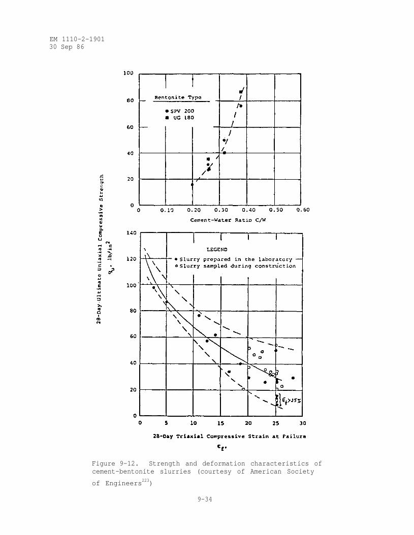
EM 1110-2-190130 Sep 86
Figure 9-12. Strength and deformation characteristics ofcement-bentonite slurries (courtesy of American Society
of Engineers223)
9-34
EM 1110-2-1901
30 Sep 86
(a) Introduction. Several mechanisms can affect the functioning ofslurry walls and cause failure. Failure may occur during excavation of thetrench, upon first filling of the reservoir with the resulting rise in differ-ential head acting across the slurry wall, or at some future time due toadverse chemical substances in the soil and ground water. Specific failuremechanisms include trench collapse, gaps (or windows) in the slurry wall,inadequate aquiclude key-in, blowout or piping of backfill material into thesurrounding pervious foundation, and chemical destruction of the slurry wall(Spooner et al. 1982).
(b) Trench Collapse. Trench collapse is caused by instability of thetrench walls during excavation and before backfilling (for soil-bentoniteslurry trench) or setup (for cement-bentonite slurry trench). Causes of trenchcollapse include failure to maintain the minimum differential head between thetop of the slurry and the top of the ground water and/or too low unit weight ofslurry (see figure 9-7). Drop in the slurry level in the trench may be causedby contact with gravel, fissures, etc., during excavation, while rise in theground-water level may be caused by surface runoff into cracks adjacent to thetrench, particularly following heavy rainfall. Too low unit weight of theslurry may be caused by the cessation of agitation by excavation equipment overthe week end (Spooner et al. 1982). Such a set of circumstances contributed tothe collapse of a portion of one wall of a soil-cement bentonite slurry trenchat Duncan Dam in Canada (Duguid et al. 1971).
(c) Gaps (or Windows) in the Slurry Wall. Trench collapse or improperplacement of backfill can create gaps (or windows) which result in zones ofhigher permeability as well as variations in wall thickness and strength(Spooner et al. 1982). The continuity of the trench should be tested beforebackfilling by passing the bucket or clamshell of the excavating tool verti-cally and horizontally along each segment of the trench. As mentioned pre-viously, for soil-bentonite slurry trenches irregularities in the backfillslope are indications that pockets of clean material (slurry not mixed inproperly or was washed out) or slurry were trapped in the backfill or that thebackfill does not contain sufficient sand or coarse material.
(d) Inadequate Aquiclude Key-In. As discussed previously, inadequateaquiclude key-in will permit seepage under the cutoff. Inadequate key-in canresult from variations in trench depth, insufficient aquiclude penetration,trench collapse, or the presence of boulders (Spooner et al. 1982).
(e) Blowout or Piping of Backfill Material. As mentioned previously,blowout or piping of backfill material into the surrounding pervious founda-tion is especially critical for soil-bentonite slurry trenches when the foun-dation contains openwork gravel. The required width of the slurry trench toprevent blowout (factor of safety of 3) in openwork gravel may be estimatedfrom Equation 9-11.
(f) Chemical Destruction of the Slurry Wall. Chemical substances inthe foundation soil and ground water can affect the durability of the slurrywall once it is constructed. If salt water is present in the constructionarea, appapulgite may be used instead of bentonite. Permeation of a soil-bentonite or cement-bentonite slurry wall by polluted ground water generally
9-35
EM 1110-2-190130 Sep 86
leads to increased permeability. The bentonite may become entrained in thesolution and the cement may become slurry solubilized as a solution channel iscreated through the slurry wall and into the foundation. Chemicals may alsoprevent the slurry from forming an adequate filter cake along the sides of thesoil-bentonite slurry trench (Spooner et al. 1982). Where polluted groundwater is present, long-term permeability tests should be conducted using thespecific soil-bentonite backfill materials or cement-bentonite mix from thesite permeated by the actual pollutant in designing the slurry trench cutoff(Spooner et al. 1982 and D'Appolonia 1980).
(7) Instrumentation and Monitoring.
(a) Introduction. Whenever a slurry trench is used for control ofunderseepage, the initial filling of the reservoir must be controlled andinstrumentation monitored to determine if the slurry trench is performing asplanned. If the slurry trench cutoff is ineffective, remedial seepage controlmeasures must be installed prior to further raising of the reservoir pool(EM 1110-2-2300).
(b) Parameters of Interest. There are two parameters of interest withregard to slurry trench cutoffs for control of underseepage. These are thedrop in piezometric head from upstream to downstream across the trench duringreservoir filling and the differential settlement between the top of theslurry trench and the overlying compacted embankment material.
(c) Efficiency of Slurry Trench Cutoff. To evaluate the head effi-ciency (see equation 2) of the slurry trench cutoff, the head loss is deter-mined between points immediately upstream and downstream of the slurry trenchcutoff wall at its junction with the base of the dam. The head loss isestablished from piezometer readings taken during construction, before andduring initial filling of the reservoir, and subsequently as frequently asnecessary to determine changes that are occurring and to assess their impli-cations with respect to safety of the dam (see Chapter 13). Equal numbers ofpiezometers are normally placed on each side of the slurry trench cutoff.Piezometers should be installed at two or more locations along the length ofthe slurry trench depending upon the foundation conditions at the site.Pneumatic piezometers installed upstream and downstream of the soil-bentoniteslurry trench at West Point Dam, Alabama and Georgia, showed a near-horizontalpiezometric surface existed across the trench prior to filling the reservoir.Piezometer readings taken after reservoir filling indicated a drop in piezom-eter head from upstream to downstream across the slurry trench, confirming theeffectiveness of the cutoff (U. S. Army Engineer District, Savannah 1979).Open-tube piezometers installed upstream and downstream of the soil-bentoniteslurry trench at Addicka Dam, Texas, indicated a drop in piezometric headacross the slurry trench (U. S. Army Engineer District, Galveston 1983).
(d) Differential Settlement. The differential settlement between thetop of the slurry trench and the overlying compacted embankment material isimportant because a separation of materials in this region could result inpiping at the interface between the embankment and the foundation. Settlementplates placed on top of the soil-cement bentonite slurry trench at West PointDam, Alabama and Georgia, indicated a uniform total settlement of approximately
9-36
EM 1110-2-190130 Sep 86
0.5 ft throughout the trench. Excavation of a portion of the trench prior tofilling the reservoir showed no void between the slurry trench backfill and theoverlying compacted fill (U. S. Army Engineer District, Savannah 1968 and1979).
e. Concrete Wall.
(1) Introduction. When the depth of the pervious foundation is exces-sive (< 150 ft) and/or the foundation contains cobbles, boulders, or cavernouslimestone, the concrete cutoff wall may be an effective method for control ofunderseepage. Using this method, a cast-in-place continuous concrete wall isconstructed by tremie placement of concrete in a bentonite slurry supportedtrench. Two general types of concrete cutoff walls, the panel wall and theelement wall have been used, as shown in figures 9-13 and 9-14, respectively.Since the wall in its simpler structural form is a rigid diaphragm, earth-quakes could cause its rupture; therefore, cutoff walls should not be used ata site where strong earthquake shocks are likely (U. S. Army EngineerDistrict, Pittsburgh 1965).
(2) History of Use. Conventional (excavated without bentonite slurry)concrete cutoff walls were widely used prior to 1925. Since they requireabout the same excavation and dewatering as compacted backfill trenches andthe wall itself is far more expensive than compacted soil, the popularity ofconventional concrete cutoff walls has declined (Sowers 1962 and Sherard et al.1963). The method of excavating trenches supported by bentonite for the con-struction of cast-in-place concrete cutoff walls was used for the first timein 1951 at the Volturno-Garigliano hydroelectric plant on the Volturno Riverat Venafro, near Naples, Italy (Veder 1963, Veder 1975 and Franke 1954). Sincethe 1950's, concrete cutoff walls constructed by tremie placement of concretein a bentonite slurry supported trench have been used for projects throughoutthe world. The deepest concrete cutoff wall to date was constructed atManicouagan 3 Dam in Quebec, Canada, in 1972, where two parallel concretewalls, 2 ft thick and 10 ft apart, extended 430 ft deep (Anonymous 1972). Acomparison of concrete cutoff walls constructed at Corps of Engineers dams isgiven in table 9-7.
(3) Sequence of Construction and Location of Wall. Normally theembankment is constructed first, followed by the concrete cutoff wall locatedupstream of the toe of the dam as was done at Kinzua Dam (formerly AlleghenyDam) and tied into the core of the dam with an impervious blanket (U. S. ArmyEngineer District, Pittsburgh 1965). The upstream location minimizes the pos-sibility of compressive failure of the concrete cutoff wall due to negativeskin friction as the foundation settles under the weight of the embankment (aswould occur is the cutoff wall is located under the center of the dam). Con-structing the embankment first, followed by the concrete cutoff wall, minimizesthe possibility of rupture of the concrete cutoff wall due to horizontal move-ment of the foundation as the embankment is constructed. For remedial seepagecontrol of existing dams (see Chapter 12) where it is not practical to drawdown the reservoir and primary consolidation of the foundation has beencomplete, a central location for the concrete cutoff wall may be feasible.
9-37
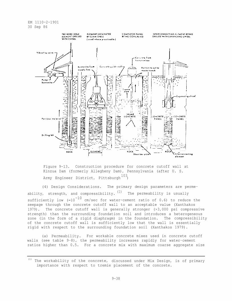
EM 1110-2-190130 Sep 86
Figure 9-13. Construction procedure for concrete cutoff wall atKinzua Dam (formerly Allegheny Dam), Pennsylvania (after U. S.
Army Engineer District, Pittsburgh103
)
(4) Design Considerations. The primary design parameters are perme-
ability, strength, and compressibility. (1) The permeability is usually
sufficiently low (=10-10 cm/sec for water-cement ratio of 0.6) to reduce the
seepage through the concrete cutoff wall to an acceptable value (Xanthakos1979). The concrete cutoff wall is generally stronger (>3,000 psi compressivestrength) than the surrounding foundation soil and introduces a heterogeneouszone (in the form of a rigid diaphragm) in the foundation. The compressibilityof the concrete cutoff wall is sufficiently low that the wall is essentiallyrigid with respect to the surrounding foundation soil (Xanthakos 1979).
(a) Permeability. For workable concrete mixes used in concrete cutoffwalls (see table 9-8), the permeability increases rapidly for water-cementratios higher than 0.5. For a concrete mix with maximum coarse aggregate size
(1) The workability of the concrete, discussed under Mix Design, is of primaryimportance with respect to tremie placement of the concrete.
9-38
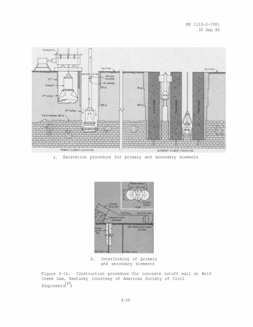
EM 1110-2-190130 Sep 86
a. Excavation procedure for primary and secondary elements
b. Interlocking of primaryand secondary elements
Figure 9-14. Construction procedure for concrete cutoff wall at WolfCreek Dam, Kentucky (courtesy of American Society of Civil
160Engineers )
9-39
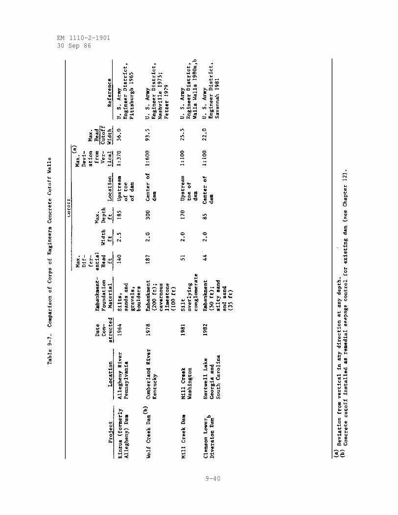
EM 1110-2-190130 Sep 86
9-40
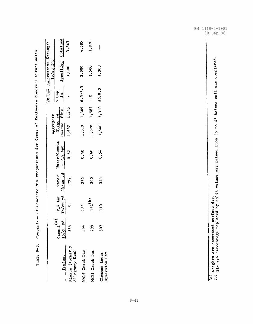
EM 1110-2-190130 Sep 86
9-41
EM 1110-2-190130 Sep 86
of 3/4 in. and a water cement ratio of 0.6, the permeability is usually lower
than 10-10
cm/sec (Xanthakos 1979). The permeability of a concrete cutoffwall is influenced by cracks in the finished structure and/or by void spacesleft in the concrete as a result of honeycombing or segregation (see Equa-tion 9-4 and figure 9-5). The joints between panels are not completelyimpermeable but the penetration of bentonite slurry into the soil in theimmediate vicinity of the joint usually keeps the flow of water very small(Hanna 1978). Measured head efficiency for concrete cutoff walls frompiezometric data generally exceeds 90 percent (Telling, Menzies, and Simons1978b). At Kinzua Dam (formerly Allegheny Dam), the measured head efficiencywas 100 percent, i.e., the head just downstream of the concrete cutoff wall wasof the magnitude established by vertical seepage through the upstreamconnecting blanket (Fuquay 1968).
(b) Strength. The compressive strength for concrete cutoff walls isgenerally specified to exceed 3,000 lb/sq in. (see table 9-8). Therefore, theconcrete cutoff wall is generally stronger than the surrounding foundationsoil. The most important factor influencing the strength of the concrete isthe water-cement ratio. The concrete's fluidity, i.e., ability to travelthrough the tremie and fill the excavation, also depends upon the water-cementratio. Too low a water-cement ratio would decrease flowability and increasecompressive strength. Too high a water-cement ratio would promote segrega-tion. A good balance is achieved with a water-cement ratio near 0.5 whichresults in a 28-day compressive strength exceeding 3,000 lb/sq in. (seetable 9-8). Cement continues to hydrate and concrete continues to increase incompressive strength, at a decreasing rate, long after 28 days (Winter andNilson 1979).
(c) Compressibility. The concrete cutoff wall is essentially rigid andhas low compressibility compared to the surrounding foundation soil. Themodulus of elasticity for concrete cutoff walls may be approximated from(Winter and Nilson 1979)
(9-13)
where
= modulus of elasticity in lb/sq in.
W = unit weight of concrete in lb/cu ft
= compressive strength of concrete in lb/sq in.
(5) Mix Design. In addition to strength, workability is an importantrequirement for the concrete mix. The mix must not segregate during place-ment. Too high a water-cement ratio or too low a cement content (with a goodwater-cement ratio) will tend to segregate. Natural well rounded aggregateincreases flowability and allows the use of less cement than an angular
9-42
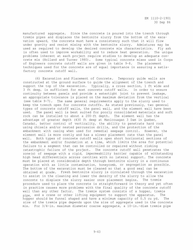
EM 1110-2-190130 Sep 86
manufactured aggregate. Since the concrete is poured into the trench throughtremie pipes and displaces the bentonite slurry from the bottom of the exca-vation upward, the concrete must have a consistency such that it will flowunder gravity and resist mixing with the bentonite slurry. Admixtures may beused as required to develop the desired concrete mix characteristics. Fly ashis often used to improve workability and to reduce heat generation. The uniqueproblems inherent at each project require studies to develop an adequate con-crete mix (Holland and Turner 1980). Some typical concrete mixes used in Corpsof Engineers concrete cutoff walls are given in table 9-8. The placementtechniques used for the concrete are of equal importance in assuring a satis-factory concrete cutoff wall.
(6) Excavation and Placement of Concrete. Temporary guide walls areconstructed at the ground surface to guide the alignment of the trench andsupport the top of the excavation. Typically, a cross section, 1 ft wide and3 ft deep, is sufficient for most concrete cutoff walls. In order to ensurecontinuity between panels and provide a watertight joint to prevent leakage,an appropriate tolerance is placed on the maximum deviation from the vertical(see table 9-7). The same general requirements apply to the slurry used tokeep the trench open for concrete cutoffs. As stated previously, two generaltypes of concrete cutoff walls, the panel wall, and the element wall have beenused. The panel wall is best suited for poorly consolidated materials and softrock can be installed to about a 200-ft depth. The element wall has theadvantage of greater depth (430 ft deep at Manicouagan 3 Dam in Quebec,Canada), better control of verticality, the ability to penetrate hard rockusing chisels and/or nested percussion drills, and the protection of theembankment with casing when used for remedial seepage control. However, theelement wall is more costly and has a slower placement rate than the panelwall. Both types of concrete cutoff walls open short horizontal sections ofthe embankment and/or foundation at a time, which limits the area for potentialfailure to a segment that can be controlled or repaired without riskingcatastrophic failure of the project. The concrete cutoff wall penetrates thezone(s) of seepage with a rigid, impermeability barrier capable of withstandinghigh head differentials across cavities with no lateral support. The concretemust be placed at considerable depth through bentonite slurry in a continuousoperation with as little contamination, honeycomb, or segregation as possible.The bottom of the excavation must be cleaned so that a good seal can beobtained at grade. Fresh bentonite slurry is circulated through the excavationto assist in the cleaning and lower the density of the slurry to allow theconcrete to displace the slurry easier once placement begins. The tremieprocedure used to place the concrete is straightforward in theory and yet oftenin practice causes more problems with the final quality of the concrete cutoffwall than any other factor. The tremie system consists of a hopper, tremiepipe, and a crane or other lifting equipment to support the apparatus. Thehopper should be funnel shaped and have a minimum capacity of 0.5 cu yd. Thesize of the tremie pipe depends upon the size of aggregate used in the concretemix. For 3/4-in. maximum diameter coarse aggregate, a 10-in.-diam tremie pipe
9-43
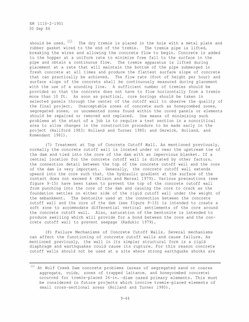
EM 1110-2-190130 Sep 86
should be used. (1) The dry tremie is placed in the hole with a metal plate andrubber gasket wired to the end of the tremie. The tremie pipe is lifted,breaking the wires and allowing the concrete flow to begin. Concrete is addedto the hopper at a uniform rate to minimize free fall to the surface in thepipe and obtain a continuous flow. The tremie apparatus is lifted duringplacement at a rate that will maintain the bottom of the pipe submerged infresh concrete at all times and produce the flattest surface slope of concretethat can practically be achieved. The flow rate (foot of height per hour) andsurface slope of the concrete shall be continuously measured during placementwith the use of a sounding line. A sufficient number of tremies should beprovided so that the concrete does not have to flow horizontally from a tremiemore than 10 ft. As soon as practical, core borings should be taken inselected panels through the center of the cutoff wall to observe the quality ofthe final project. Unacceptable zones of concrete such as honeycombed zones,segregated zones, or uncemented zones found within the cored panels or elementsshould be repaired or removed and replaced. One means of minimizing suchproblems at the start of a job is to require a test section in a noncriticalarea to allow changes in the construction procedure to be made early in theproject (Hallford 1983; Holland and Turner 1980; and Gerwick, Holland, andKomendant 1981).
(7) Treatment at Top of Concrete Cutoff Wall. As mentioned previously,normally the concrete cutoff wall is located under or near the upstream toe ofthe dam and tied into the core of the dam with an impervious blanket. If acentral location for the concrete cutoff wall is dictated by other factors,the connection detail between the top of the concrete cutoff wall and the coreof the dam is very important. Generally, the concrete cutoff wall extendsupward into the core such that, the hydraulic gradient at the surface of thecontact does not exceed 4 (Wilson and Marsal 1979). Various precautions (seefigure 9-15) have been taken to prevent the top of the concrete cutoff wallfrom punching into the core of the dam and causing the core to crack as thefoundation settles on either side of the rigid cutoff wall under the weight ofthe embankment. The bentonite used at the connection between the concretecutoff wall and the core of the dam (see figure 9-15) is intended to create asoft zone to accommodate differential vertical settlements of the core aroundthe concrete cutoff wall. Also, saturation of the bentonite is intended toproduce swelling which will provide for a bond between the core and the con-crete cutoff wall to prevent seepage (Radukic 1979).
(8) Failure Mechanisms of Concrete Cutoff Walls. Several mechanismscan affect the functioning of concrete cutoff walls and cause failure. Asmentioned previously, the wall in its simpler structural form is a rigiddiaphragm and earthquakes could cause its rupture. For this reason concretecutoff walls should not be used at a site where strong earthquake shocks are
(1) At Wolf Creek Dam concrete problems (areas of segregated sand or coarseaggregate, voids, zones of trapped laitance, and honeycombed concrete)occurred for tremie-placed 26-in. -diam cased primary elements. This mustbe considered in future projects which involve tremie-placed elements ofsmall cross-sectional areas (Holland and Turner 1980).
9-44
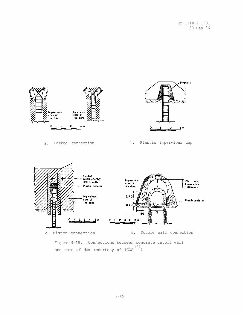
EM 1110-2-190130 Sep 86
a. Forked connection
c. Piston connection
b. Plastic impervious cap
d. Double wall connection
Figure 9-15. Connections between concrete cutoff wall
and core of dam (courtesy of ICOS182
)
9-45
EM 1110-2-1901
30 Sep 86
likely. Concrete cutoff walls located under or near the toe of the dam aresubject to possible rupture from horizontal movements of the foundation soilduring embankment construction. This effect can be minimized by constructingthe dam embankment prior to the concrete cutoff wall. As mentioned previously,concrete cutoff walls located under the center of the dam are subject to pos-sible compressive failure due to negative skin friction as the foundationsettles under the weight of the embankment. The probability of this occurringwould depend upon the magnitude of the negative skin friction developed at theinterface between the concrete cutoff wall and the foundation soil and thestress-strain characteristics of the concrete cutoff wall. Also, as previouslymentioned, a centrally located concrete cutoff wall may punch into and crackthe overlying core material unless an adequate connection is provided betweenthe concrete cutoff wall and the core of the dam.
(9) Instrumentation and Monitoring. Whenever a concrete cutoff wall isused for control of underseepage, the initial filling of the reservoir must becontrolled and instrumentation monitored to determine if the concrete cutoffwall is performing as planned. If the concrete cutoff wall is ineffective,remedial seepage control measures must be installed prior to further raisingthe reservoir pool. When the embankment is constructed first, followed by theconcrete cutoff wall located upstream of the toe of the dam, as was done atKinzua (formerly Allegheny Dam), the parameters of interest are the drop inpiezometric head from upstream to downstream across the concrete cutoff wall,differential vertical settlement between the upstream impervious blanket andthe top of the concrete cutoff wall, and vertical and horizontal movement ofthe concrete cutoff wall due to reservoir filling. If a central location forthe concrete cutoff wall is dictated by others factors, the parameters ofinterest are the drop in piezometric head from upstream to downstream acrossthe cutoff wall, differential vertical settlement between the core of the damand the top of the concrete cutoff wall, and vertical and horizontal movementof the concrete cutoff wall due to construction of the embankment and reser-voir filling. Instrumentation data should be obtained during construction,before and during initial filling of the reservoir, and subsequently as fre-quently as necessary to determine changes that are occurring and to assesstheir implications with respect to the safety of the dam (see Chapter 13).The head efficiency for concrete cutoff walls is evaluated in the same manneras described previously for slurry trench cutoffs. As previously mentioned,measured head efficiency for concrete cutoff walls generally exceeds90 percent.
f. Steel Sheetpiling.
(1) Introduction. Steel sheetpiling is rolled steel members withinterlocking joints along their edges. Sheetpiling is produced in straightweb, arch web, and Z sections in a graduated series of weights joined byinterlocks to form a continuous cutoff wall as shown in figure 9-16. Steelsheetpiling is not recommended for use as a cutoff to prevent underseepagebeneath dams due to the low head efficiency. Steel sheetpiling is frequentlyused in conjunction with concrete flood control and navigation structures toconfine the foundation soil to prevent it from piping out from under thestructure (EM 1110-2-2300 and Greer, Moorhouse, and Millet 1969).
9-46
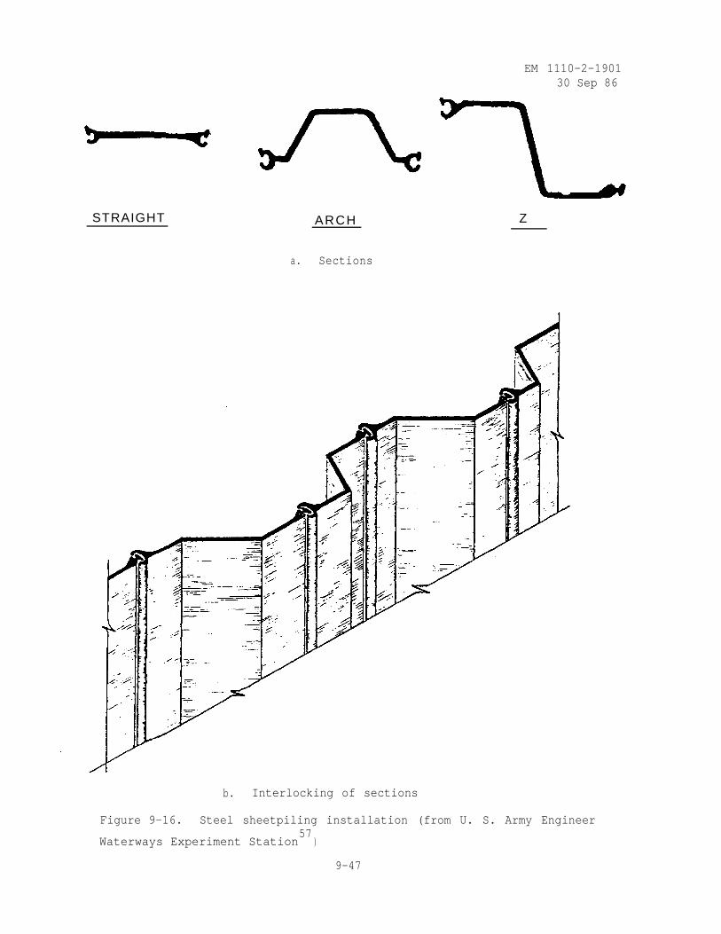
EM 1110-2-190130 Sep 86
STRAIGHT ARCH Z
a. Sections
b. Interlocking of sections
Figure 9-16. Steel sheetpiling installation (from U. S. Army Engineer
Waterways Experiment Station57
)
9-47
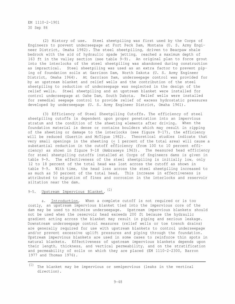
EM 1110-2-190130 Sep 86
(2) History of use. Steel sheetpiling was first used by the Corps ofEngineers to prevent underseepage at Fort Peck Dam, Montana (U. S. Army Engi-neer District, Omaha 1982). The steel sheetpiling, driven to Bearpaw shalebedrock with the aid of hydraulic spade jetting, reached a maximum depth of163 ft in the valley section (see table 9-9). An original plan to force groutinto the interlocks of the steel sheetpiling was abandoned during constructionas impractical. Steel sheetpiling was used as an extra factor to prevent pip-ing of foundation soils at Garrison Dam, North Dakota (U. S. Army EngineerDistrict, Omaha 1964). At Garrison Dam, underseepage control was provided forby an upstream blanket and relief wells and the contribution of the steelsheetpiling to reduction of underseepage was neglected in the design of therelief wells. Steel sheetpiling and an upstream blanket were installed forcontrol underseepage at Oahe Dam, South Dakota. Relief wells were installedfor remedial seepage control to provide relief of excess hydrostatic pressuresdeveloped by underseepage (U. S. Army Engineer District, Omaha 1961).
(3) Efficiency of Steel Sheetpiling Cutoffs. The efficiency of steelsheetpiling cutoffs is dependent upon proper penetration into an imperviousstratum and the condition of the sheeting elements after driving. When thefoundation material is dense or contains boulders which may result in rippingof the sheeting or damage to the interlocks (see figure 9-17), the efficiencywill be reduced (Guertin and McTigue 1982). Theoretical studies indicate thatvery small openings in the sheeting (< 1 percent of the total area) will cause asubstantial reduction in the cutoff efficiency (from 100 to 10 percent effi-ciency) as shown in figure 9-18 (Ambraseys 1963). The measured head efficiencyfor steel sheetpiling cutoffs installed at Corps of Engineers dams is given intable 9-9. The effectiveness of the steel sheetpiling is initially low, only12 to 18 percent of the total head was lost across the cutoff as shown intable 9-9. With time, the head loss across the steel sheetpiling increased toas much as 50 percent of the total head. This increase in effectiveness isattributed to migration of fines and corrosion in the interlocks and reservoirsiltation near the dam.
9-5. Upstream Impervious Blanket. (1)
a. Introduction. When a complete cutoff is not required or is toocostly, an upstream impervious blanket tied into the impervious core of thedam may be used to minimize underseepage. Upstream impervious blankets shouldnot be used when the reservoir head exceeds 200 ft because the hydraulicgradient acting across the blanket may result in piping and serious leakage.Downstream underseepage control measures (relief wells or toe trench drains)are generally required for use with upstream blankets to control underseepageand/or prevent excessive uplift pressures and piping through the foundation.Upstream impervious blankets are used in some cases to reinforce thin spots innatural blankets. Effectiveness of upstream impervious blankets depends upontheir length, thickness, and vertical permeability, and on the stratificationand permeability of soils on which they are placed (EM 1110-2-2300, Barron1977 and Thomas 1976).
(1) The blanket may be impervious or semipervious (leaks in the verticaldirection).
9-48
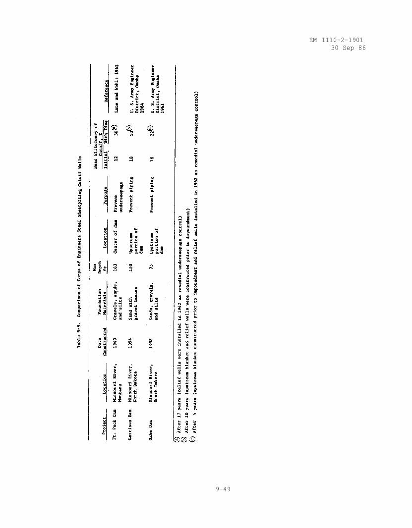
EM 1110-2-190130 Sep 86
9-49
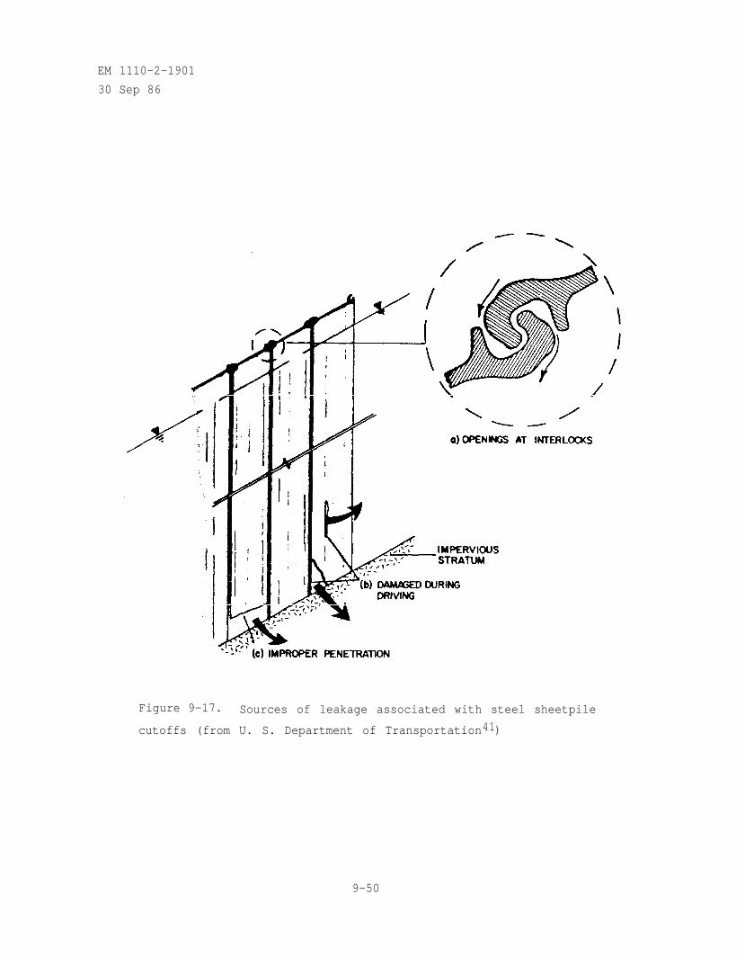
EM 1110-2-1901
30 Sep 86
Figure 9-17. Sources of leakage associated with steel sheetpile
cutoffs (from U. S. Department of Transportation41)
9-50
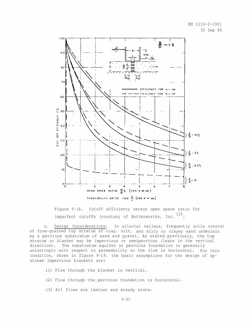
EM 1110-2-1901
30 Sep 86
Figure 9-18. Cutoff efficiency versus open space ratio for
imperfect cutoffs (courtesy of Butterworths, Inc.129
)
b. Design Considerations. In alluvial valleys, frequently soils consistof fine-grained top stratum of clay, silt, and silty or clayey sand underlainby a pervious substratum of sand and gravel. As stated previously, the topstratum or blanket may be impervious or semipervious (leaks in the verticaldirection). The substratum aquifer or pervious foundation is generallyanisotropic with respect to permeability so the flow is horizontal. For thiscondition, shown in figure 9-19, the basic assumptions for the design of up-stream impervious blankets are:
(1) Flow through the blanket is vertical.
(2) Flow through the pervious foundation is horizontal.
(3) All flows are laminar and steady state.
9-51
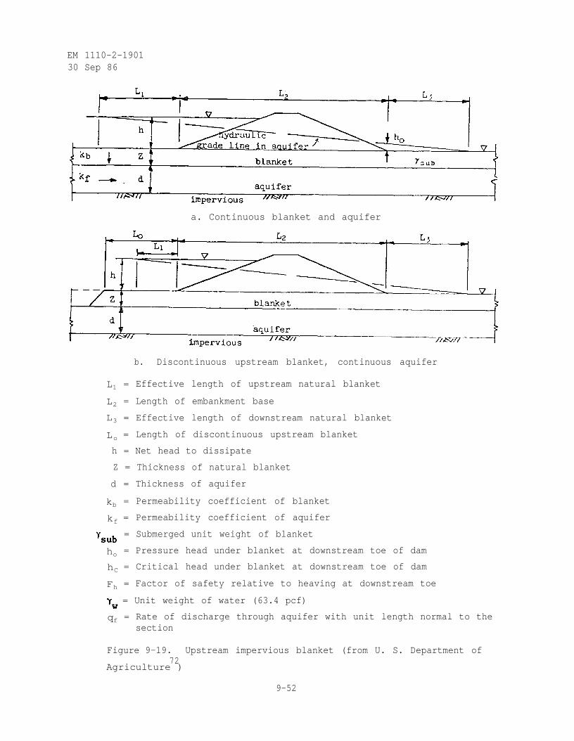
EM 1110-2-190130 Sep 86
a. Continuous blanket and aquifer
b. Discontinuous upstream blanket, continuous aquifer
L1 = Effective length of upstream natural blanket
L2 = Length of embankment base
L3 = Effective length of downstream natural blanket
Lo = Length of discontinuous upstream blanket
h = Net head to dissipate
Z = Thickness of natural blanket
kb
= Thickness of aquifer
= Permeability coefficient of blanket
kf = Permeability coefficient of aquifer
d
= Submerged unit weight of blanket
ho = Pressure head under blanket at downstream toe of dam
hC = Critical head under blanket at downstream toe of dam
Fh = Factor of safety relative to heaving at downstream toe
= Unit weight of water (63.4 pcf)
qf = Rate of discharge through aquifer with unit length normal to thesection
Figure 9-19. Upstream impervious blanket (from U. S. Department of72
Agriculture )
9-52
EM 1110-2-190130 Sep 86
(4) The dam (or core of a zoned embankment) is impervious.
(5) Both the blanket and substratum have a constant thickness and arehorizontal.
When the top stratum or pervious foundation consists of several layers ofdifferent soils, they must be transformed into a single stratum with aneffective thickness and permeability (see procedure given in U. S. ArmyEngineer Waterways Experiment Station 1956a). For the upstream imperviousblanket shown in figure 9-19, the effective length of the upstream blanket is
where
L1 = effective length of upstream blanket
kf = horizontal permeability of pervious foundation
k b R = vertical permeability of upstream blanket
ZbR = thickness of upstream blanket
d = thickness of pervious foundation
The effective length of the downstream blanket is
where
(9-14)
(9-15)
L3 = effective length of downstream blanket
kbL = vertical permeability of downstream blanket
ZbL = thickness of downstream blanket
Upstream blankets should be designed so that under maximum reservoirconditions the pressure head under the blanket at the downstream toe of thedam and the rate of discharge through the pervious foundation are acceptable.The pressure head under the blanket at the downstream toe of the dam (seefigure 9-19) is
9-53
EM 1110-2-1901
30 Sep 86
(9-16)
where
ho = pressure head under the blanket at the downstream toe of the dam
h = net head to dissipate
L2 = length of impervious core or dam base
The critical pressure head under the blanket at the downstream toe of the damis
(9-17)
where
hc = critical pressure head under the blanket at the downstream toe ofthe dam
= submerged unit weight of downstream blanket soil
= unit weight of water
The factor of safety against uplift or heaving at the downstream toe of the damis
(9-18)
where Fh is the factor of safety against uplift or heaving at the downstream
toe of the dam. Generally dams are designed without relying upon naturaldownstream blankets because it is difficult to assure the continuity and theexistence of the blanket throughout the life of the structure. Also, down-stream seepage control measures (relief wells or trench drains) are generallyused with upstream blankets to reduce uplift or heaving at the downstream toeof the dam. However, for the exceptional case where the dam is designed with anatural downstream blanket and with no downstream seepage control measures(relief wells or trench drains), upstream blankets should be designed so thatthe factor of safety against uplift or heaving at the downstream toe of the damis at least 3. The rate of discharge through the pervious foundation per unitlength of dam (see figure 9-19) is
9-54
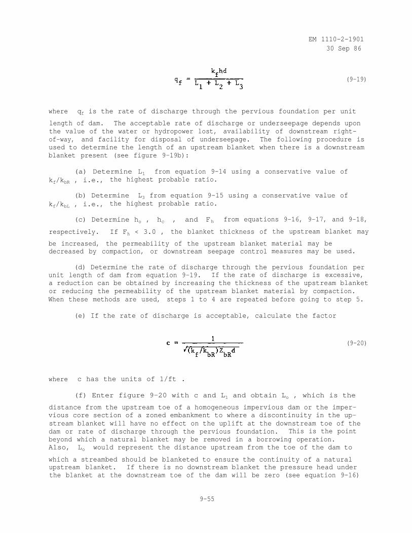
EM 1110-2-190130 Sep 86
(9-19)
where qf is the rate of discharge through the pervious foundation per unit
length of dam. The acceptable rate of discharge or underseepage depends uponthe value of the water or hydropower lost, availability of downstream right-of-way, and facility for disposal of underseepage. The following procedure isused to determine the length of an upstream blanket when there is a downstreamblanket present (see figure 9-19b):
(a) Determine L1 from equation 9-14 using a conservative value ofkf/kbR , i.e., the highest probable ratio.
(b) Determinekf/kbL , i.e.,
L3 from equation 9-15 using a conservative value ofthe highest probable ratio.
(c) Determine ho , hc , and Fh from equations 9-16, 9-17, and 9-18,
respectively. If Fh < 3.0 , the blanket thickness of
be increased, the permeability of the upstream blanketdecreased by compaction, or downstream seepage control
(d) Determine the rate of discharge through theunit length of dam from equation 9-19. If the rate of
the upstream blanket may
material may bemeasures may be used.
pervious foundation perdischarge is excessive,
a reduction can be obtained by increasing the thickness of the upstream blanketor reducing the permeability of the upstream blanket material by compaction.When these methods are used, steps 1 to 4 are repeated before going to step 5.
(e) If the rate of discharge is acceptable, calculate the factor
(9-20)
where c has the units of 1/ft .
(f) Enter figure 9-20 with c and L1 and obtain Lo , which is the
distance from the upstream toe of a homogeneous impervious dam or the imper-vious core section of a zoned embankment to where a discontinuity in the up-stream blanket will have no effect on the uplift at the downstream toe of thedam or rate of discharge through the pervious foundation. This is the pointbeyond which a natural blanket may be removed in a borrowing operation.Also, Lo would represent the distance upstream from the toe of the dam to
which a streambed should be blanketed to ensure the continuity of a naturalupstream blanket. If there is no downstream blanket the pressure head underthe blanket at the downstream toe of the dam will be zero (see equation 9-16)
9-55
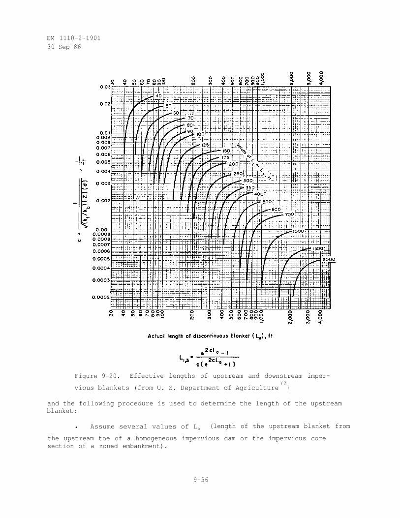
EM 1110-2-190130 Sep 86
Figure 9-20. Effective lengths of upstream and downstream imper-
vious blankets (from U. S. Department of Agriculture72
)
and the following procedure is used to determine the length of the upstreamblanket:
• Assume several values of Lo (length of the upstream blanket from
the upstream toe of a homogeneous impervious dam or the impervious coresection of a zoned embankment).
9-56
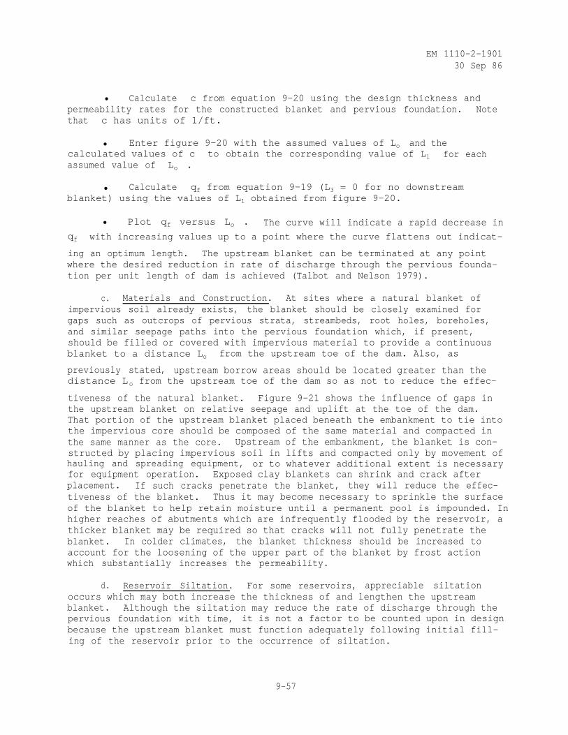
EM 1110-2-190130 Sep 86
• Calculate c from equation 9-20 using the design thickness andpermeability rates for the constructed blanket and pervious foundation. Notethat c has units of 1/ft.
• Enter figure 9-20 with the assumed values of Lo and thecalculated values of c to obtain the corresponding value of Ll for eachassumed value of Lo .
• Calculate qf from equation 9-19 (L3 = 0 for no downstreamblanket) using the values of L1 obtained from figure 9-20.
• Plot qf versus Lo . The curve will indicate a rapid decrease in
qf with increasing values up to a point where the curve flattens out indicat-
ing an optimum length. The upstream blanket can be terminated at any pointwhere the desired reduction in rate of discharge through the pervious founda-tion per unit length of dam is achieved (Talbot and Nelson 1979).
c. Materials and Construction. At sites where a natural blanket ofimpervious soil already exists, the blanket should be closely examined forgaps such as outcrops of pervious strata, streambeds, root holes, boreholes,and similar seepage paths into the pervious foundation which, if present,should be filled or covered with impervious material to provide a continuousblanket to a distance Lo from the upstream toe of the dam. Also, as
previously stated, upstream borrow areas should be located greater than thedistance Lo from the upstream toe of the dam so as not to reduce the effec-
tiveness of the natural blanket. Figure 9-21 shows the influence of gaps inthe upstream blanket on relative seepage and uplift at the toe of the dam.That portion of the upstream blanket placed beneath the embankment to tie intothe impervious core should be composed of the same material and compacted inthe same manner as the core. Upstream of the embankment, the blanket is con-structed by placing impervious soil in lifts and compacted only by movement ofhauling and spreading equipment, or to whatever additional extent is necessaryfor equipment operation. Exposed clay blankets can shrink and crack afterplacement. If such cracks penetrate the blanket, they will reduce the effec-tiveness of the blanket. Thus it may become necessary to sprinkle the surfaceof the blanket to help retain moisture until a permanent pool is impounded. Inhigher reaches of abutments which are infrequently flooded by the reservoir, athicker blanket may be required so that cracks will not fully penetrate theblanket. In colder climates, the blanket thickness should be increased toaccount for the loosening of the upper part of the blanket by frost actionwhich substantially increases the permeability.
d. Reservoir Siltation. For some reservoirs, appreciable siltationoccurs which may both increase the thickness of and lengthen the upstreamblanket. Although the siltation may reduce the rate of discharge through thepervious foundation with time, it is not a factor to be counted upon in designbecause the upstream blanket must function adequately following initial fill-ing of the reservoir prior to the occurrence of siltation.
9-57
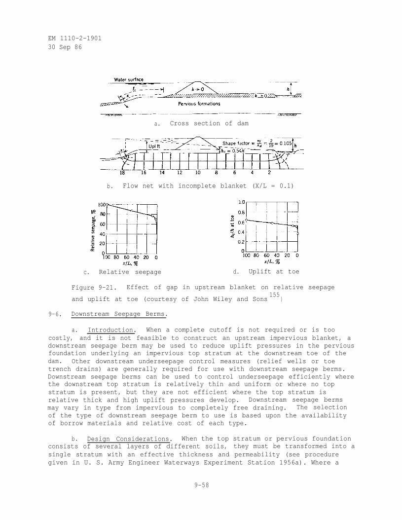
EM 1110-2-190130 Sep 86
c. Relative seepage
a. Cross section of dam
b. Flow net with incomplete blanket (X/L = 0.1)
d. Uplift at toe
Figure 9-21. Effect of gap in upstream blanket on relative seepage
and uplift at toe (courtesy of John Wiley and Sons155
)
9-6. Downstream Seepage Berms.
a. Introduction. When a complete cutoff is not required or is toocostly, and it is not feasible to construct an upstream impervious blanket, adownstream seepage berm may be used to reduce uplift pressures in the perviousfoundation underlying an impervious top stratum at the downstream toe of thedam. Other downstream underseepage control measures (relief wells or toetrench drains) are generally required for use with downstream seepage berms.Downstream seepage berms can be used to control underseepage efficiently wherethe downstream top stratum is relatively thin and uniform or where no topstratum is present, but they are not efficient where the top stratum isrelative thick and high uplift pressures develop. Downstream seepage bermsmay vary in type from impervious to completely free draining. The selectionof the type of downstream seepage berm to use is based upon the availabilityof borrow materials and relative cost of each type.
b. Design Considerations. When the top stratum or pervious foundationconsists of several layers of different soils, they must be transformed into asingle stratum with an effective thickness and permeability (see proceduregiven in U. S. Army Engineer Waterways Experiment Station 1956a). Where a
9-58
EM 1110-2-190130 Sep 86
downstream natural blanket is present, the downstream seepage berm should havea thickness so that the factor of safety against uplift or heaving at the down-stream toe of the dam is at least 3 and width so that the factor of safetyagainst uplift at the downstream toe of the seepage berm is at least 1.5.Formulas for the design of downstream seepage berms where a downstream naturalblanket is present are given in figure 9-22. If there is no downstream naturalblanket present, the need for a downstream seepage berm will be based uponBligh's creep ratio.
(9-21)
where
cB = Bligh's creep ratio
Xl = effective length of upstream blanket
L2 = length of dam base
X = width of downstream seepage berm
h = net head on dam
Minimum acceptable values of Bligh's creep ratio are given in table 9-10. Ifthe creep ratio is greater than the minimum value, a downstream seepage berm is
not required. (1) If the creep ratio is less than the minimum value, the widthof the downstream seepage berm should be made such that the creep ratio isabove the minimum value shown in table 9-10. The thickness of the downstreamseepage berm at the toe of the dam will be determined so that the factor ofsafety against uplift or heaving at the downstream toe of the dam is atleast 3. The pressure head beneath the downstream seepage berm at the landsidetoe of the levee is
(9-22)
where
ho = pressure head under the seepage berm at the downstream toe of thedam
(1) A downstream seepage berm may be required to correct other problems suchas excessive seepage gradients under the dam (could be detected by check-ing the rate of underseepage).
9-59
EM 1110-2-1901
30 Sep 86
d = thickness of pervious foundation
X1 = effective length of upstream natural blanket (taken equal to 0.43dwhere no upstream natural blanket exists)
The rate of discharge through the pervious foundation per unit length of damis
(9-23)
where
qf = rate of discharge through the pervious foundation per unit lengthof dam
kf = horizontal permeability of pervious foundation
As stated previously, the acceptable rate of discharge or underseepage dependsupon the value of the water or hydropower lost, availability of downstreamright-of-way, and facility for disposal of underseepage. Downstream seepageberms should have a minimum thickness of 10 ft at the dam toe and a minimumthickness of 5 ft at the berm toe. The computed thickness of the berm shouldbe increased 25 percent to allow for shrinkage, foundation settlements, andvariations in the design factors. Downstream seepage berms should have aslope of 1V on 50H or steeper to ensure drainage (U. S. Army Engineer WaterwaysExperiment Station 1956a).
c. Materials and Construction. As previously stated, the selection ofthe type of material used to construct the downstream seepage berm is basedupon the availability of borrow materials and relative cost of each type. Aberm constructed of impervious soil should be composed of the same material asthe impervious core. That portion of the downstream impervious seepage bermplaced beneath the embankment to tie into the impervious core should be com-pacted in the same manner as the core. Downstream of the embankment, theimpervious seepage berm is constructed by placing impervious soil in lifts andcompacting only by movement of hauling and spreading equipment, or to whateveradditional extent is necessary for equipment operation. Semipervious materialused to construct downstream seepage berms should have an in-place verticalpermeability equal to or greater than that of the upstream natural blanket andare compacted in the same manner as described previously for impervious mate-rial. Material used in a sand berm should be as pervious as possible, with
a minimum in-place vertical permeability of 100 x 10-4
cm per sec. Downstreamseepage berms constructed of sand should be compacted to an average in-placerelative density of at least 85 percent with no portion of the berm having arelative density less than 80 percent. As proper functioning of a downstreamseepage berm constructed of sand depends upon its continued perviousness, itshould not be constructed until after the downstream slope of the earth dam has
9-60
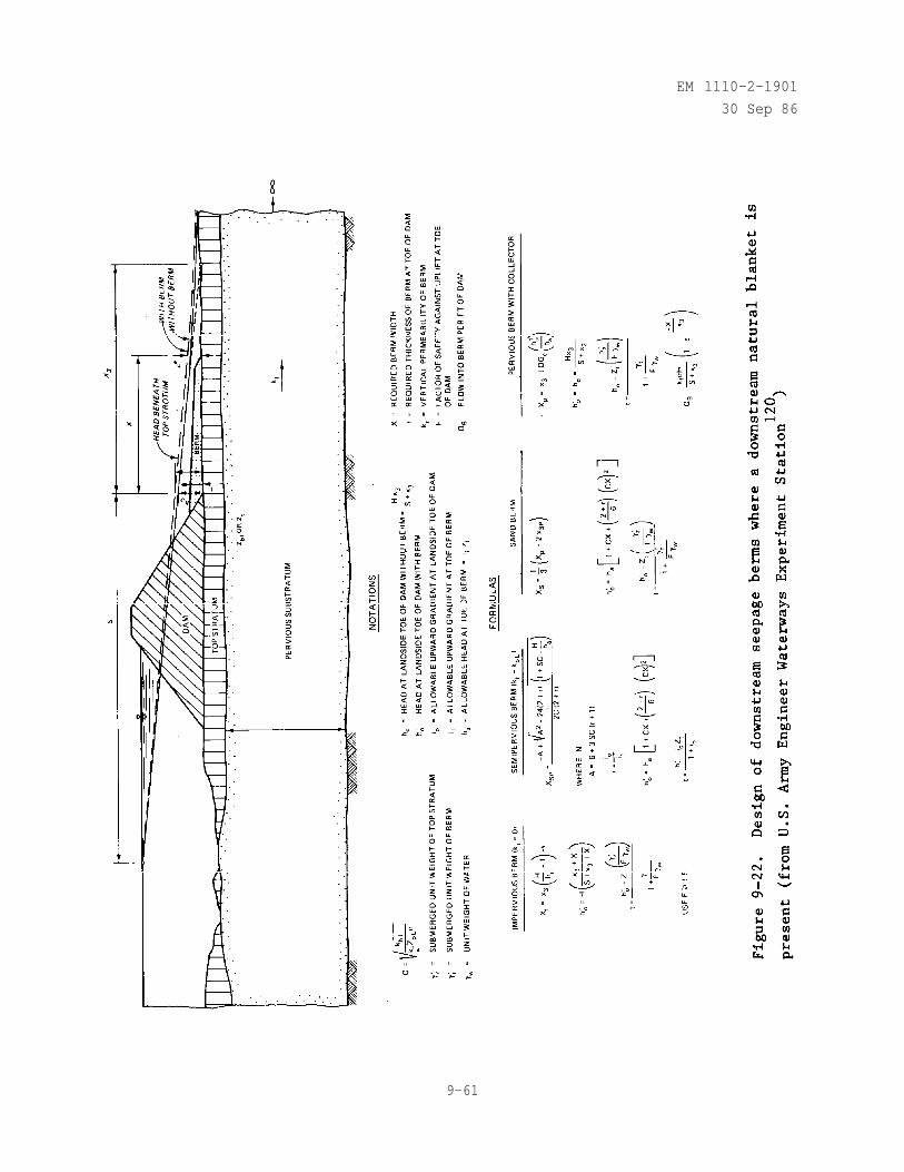
EM 1110-2-1901
30 Sep 86
9-61
EM 1110-2-1901
30 Sep 86
Table 9-10. Minimum Bligh's Creep Ratios for Dams
Founded on Pervious Foundations (a)
Material
Very fine sand or silt
Fine to medium sand
Coarse sand
Fine gravel or sand and gravel
Coarse gravel including cobbles
Minimum Bligh'sCreep Ratio
18
15
12
9
(a) From U. S. Army Engineer Waterways Experiment
Station120
become covered with sod and stabilized so that soil particles carried by sur-face runoff and erosion will not clog the seepage berm. If it is necessary toconstruct the downstream seepage berm at the time the earth dam is built orbefore it has become covered with sod, an interceptor dike should be built atthe intersection of the downstream toe of the dam and the seepage berm to pre-vent surface wash from clogging the seepage berm. A free-draining downstreamseepage berm is one composed or random fill overlying horizontal sand andgravel drainage layers with a terminal perforated collector pipe system (U. S.Army Engineer Waterways Experiment Station 1956a).
9-7. Relief Wells.
a. Introduction. When a complete cutoff is not required or is toocostly, relief wells installed along the downstream toe of the dam may be usedto prevent excessive uplift pressures and piping through the foundation.Relief wells increase the quantity of underseepage from 20 to 40 percentdepending upon the foundation conditions. Relief wells may be used in combi-nation with other underseepage control measures (upstream impervious blanketor downstream seepage berm) to prevent excessive uplift pressures and pipingthrough the foundation. Relief wells are applicable where the pervious foun-dation has a natural impervious cover. The well screen section (see fig-ure 9-23), surrounded by a filter if necessary, should penetrate into theprincipal pervious stratum to obtain pressure relief, especially where thefoundation is stratified. The wells, including screen and riser pipe, shouldhave a diameter which will permit the maximum design flow without excessivehead losses but in no instance should the inside diameter be less than6 in. Filter fabrics should not be used in conjunction with relief wells (seeAppendix D). Even in nearly homogeneous stratum, a penetration of less than50 percent results in significant rise in pressure midway between adjacentwells, or requires close spacing. Relief wells should be located so that
9-62
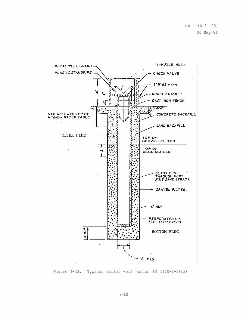
EM 1110-2-1901
30 Sep 86
Figure 9-23. Typical relief well (after EM 1110-2-1913)
9-63
EM 1110-2-190130 Sep 86
their tops are accessible for cleaning, sounding for sand, and pumping todetermine discharge capacity. Relief wells should discharge into open ditchesor into collector systems outside of the dam base which are independent of toedrains or surface drainage systems. Experience with relief wells indicatesthat with the passage of time the discharge of the wells will graduallydecrease due to clogging of the well screen and/or reservoir siltation. Acomprehensive study of the efficiency of relief wells along the MississippiRiver levee showed that the specific yield of 24 test wells decreased 33 per-cent over a 15-year period. Incrustation on well screens and in gravel filterswas believed to be the major cause (Montgomery 1972). Therefore, the amount ofwell screen area should be designed oversized and a piezometer system installedbetween the wells to measure the seepage pressure, and if necessary additionalrelief wells should be installed (EM 1110-2-2300, U. S. Army Engineer WaterwaysExperiment Station 1956a, Singh and Sharma 1976).
b. History of Use. The first use of relief wells to prevent excessiveuplift pressures at a dam was by the U. S. Army Engineer District, Omaha, when21 wells were installed from July 1942 to September 1943 as remedial seepagecontrol at Fort Peck Dam, Montana. The foundation consisted of an imperviousstratum of clay overlying pervious sand and gravel. Although a steel sheetpilecutoff was driven to shale, sufficient leakage occurred to develop high hydro-static pressure at the downstream toe that produced a head of 45 ft above thenatural ground surface. This uplift pressure was first observed in piezometersinstalled in the pervious foundation. The first surface evidence of the highhydrostatic pressure came in the form of discharge from an old well casing thathad been left in place. Since it was important that the installation be madeas quickly as possible, 4- and 6-in. well casings, available at the site, wereslotted with a cutting torch and installed in the pervious stratum with solid(riser) pipe extending to the surface. Wells were first spaced on 250-ftcenters and later intermediate wells were installed making the spacing 125 ft.The hydrostatic pressure at the downstream toe was reduced from 45 to 5 ft andthe total flow from all wells averaged 10 cu ft per sec (U. S. Army EngineerDistrict, Omaha 1982). The first use of relief wells in the original design ofa dam was by the U. S. Army Engineer District, Vicksburg, when wells wereinstalled during construction of Arkabutla Dam, Mississippi, completed in June1943. The foundation consisted of approximately 30 ft of impervious loessunderlain by a pervious stratum of sand and gravel. The relief wells wereinstalled to provide an added measure of safety with respect to uplift andpiping along the downstream toe of the embankment. The relief wells consistedof 2-in. brass wellpoint screens 15 ft long attached to 2-in. galvanizedwrought iron riser pipes spaced at 25-ft intervals located along a line 100 ftupstream of the downstream toe of the dam. The top of the well screens wasinstalled about 10 ft below the bottom of the impervious top stratum. The wellefficiency decreased over a 12-year period to about 25 percent primarily as aresult of clogging of the wells by influx of foundation materials into thescreens and/or the development of corrosion or incrustation. However, thepiezometric head along the downstream toe of the dam, including observationsmade at a time when the spillway was in operation, has not been more than 1 ftabove the ground surface except at sta 190+00 where a maximum excess hydro-static head of 9 ft was observed (U. S. Army Engineer Waterways ExperimentStation 1958). Since these early installations, relief wells have been used at
9-64
EM 1110-2-190130 Sep 86
many dams to prevent excessive uplift pressures and piping through thefoundation.
c. Design Considerations.
(1) General. The factors to be considered in determining the need forand designing a relief well system include characteristics of the landside topstratum; permeability, stratification, and depth of the pervious foundation inwhich. seepage is to be controlled; net head acting on the dam; dimensions ofthe relief well system being considered; allowable factor of safety withrespect to uplift at the downstream toe of the dam; and allowable rate of dis-charge through the pervious foundation. Some factors, like the net head act-ing on the dam, can be determined with good accuracy. Other factors likepermeability and stratification are more difficult to assess. The design ofthe relief wells should be based on the best estimate of permeability valuesand then subjected to a sensitivity analysis using several values of perme-ability to ensure that the adopted design is adequate to intercept seepage andlower uplift pressures to the required extent allowing for the likelihood thatthe values of permeability used in design lake precision (Kaufman 1976). Thearea between the dam abutments is divided into reaches where geologic and soilconditions are assumed uniform within the reach (see figure 9-24). Generally,the design procedure for relief wells consists of determining the head whichwould exist along the downstream toe of the dam without relief wells, compar-ing this head to that desired for a given factor of safety, and designing arelief well system to reduce the head to the desired value. There is nounique solution because there is an infinite number of well systems (radius,penetration, spacing, etc.) which reduce the head to the given value. Theobjective is to select one which is economical, has reasonable dimensions, andcan produce the desired results. Usually the designer selects the radius andpenetration and then determine the required spacing of the well system. Thisbecomes an iterative procedure wherein the designer assumes a value of wellspacing, computes the head between wells and repeats this for several trialspacings until a spacing is found that produces the desired head along thedownstream toe of the dam. The cost of the well system is determined and thena design can be prepared for a different penetration to determine if someeconomy can be achieved by changing the penetration of the system. Fully pene-trating relief wells are often used in aquifers up to about 75 ft thick. Forlarger depths of pervious strata, it is usually more economical to have wellsystems with 50 percent or greater penetration at closer spacing. The equa-tions for relief well design depend upon the values of the source of seepageand seepage exit length as shown in figure 9-25. The source of seepage isassumed to be a line source parallel to the well system and the dam axis. Thelocation of the source of seepage depends upon the thickness and verticalpermeability of any natural top stratum upstream of the dam and any imperviousblanket constructed upstream of the dam, the permeability and thickness of thepervious foundation, and the presence of any borrow pits and/or major erosionfeatures which reduce the thickness of the top stratum (see procedure toevaluate the source of seepage given in U. S. Army Engineer Waterways Experi-ment Station 1956a). The value of the seepage exit (X3 in figure 9-25)
depends upon the thickness and permeability of the top stratum downstream fromthe toe of the dam, the thickness and permeability of the pervious substratum,
9-65
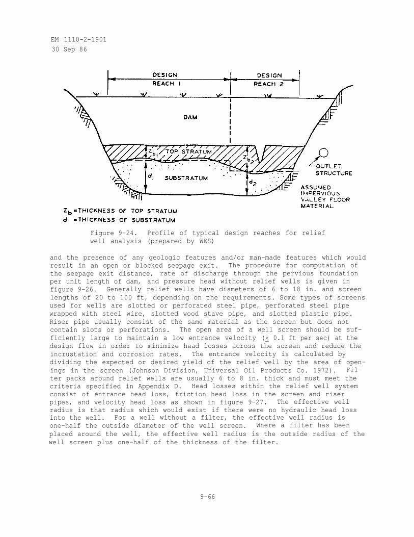
EM 1110-2-1901
30 Sep 86
Figure 9-24. Profile of typical design reaches for reliefwell analysis (prepared by WES)
and the presence of any geologic features and/or man-made features which wouldresult in an open or blocked seepage exit. The procedure for computation ofthe seepage exit distance, rate of discharge through the pervious foundationper unit length of dam, and pressure head without relief wells is given infigure 9-26. Generally relief wells have diameters of 6 to 18 in. and screenlengths of 20 to 100 ft, depending on the requirements. Some types of screensused for wells are slotted or perforated steel pipe, perforated steel pipewrapped with steel wire, slotted wood stave pipe, and slotted plastic pipe.Riser pipe usually consist of the same material as the screen but does notcontain slots or perforations. The open area of a well screen should be suf-ficiently large to maintain a low entrance velocity (< 0.1 ft per sec) at thedesign flow in order to minimize head losses across the screen and reduce theincrustation and corrosion rates. The entrance velocity is calculated bydividing the expected or desired yield of the relief well by the area of open-ings in the screen (Johnson Division, Universal Oil Products Co. 1972). Fil-ter packs around relief wells are usually 6 to 8 in. thick and must meet thecriteria specified in Appendix D. Head losses within the relief well systemconsist of entrance head loss, friction head loss in the screen and riserpipes, and velocity head loss as shown in figure 9-27. The effective wellradius is that radius which would exist if there were no hydraulic head lossinto the well. For a well without a filter, the effective well radius isone-half the outside diameter of the well screen. Where a filter has beenplaced around the well, the effective well radius is the outside radius of thewell screen plus one-half of the thickness of the filter.
9-66
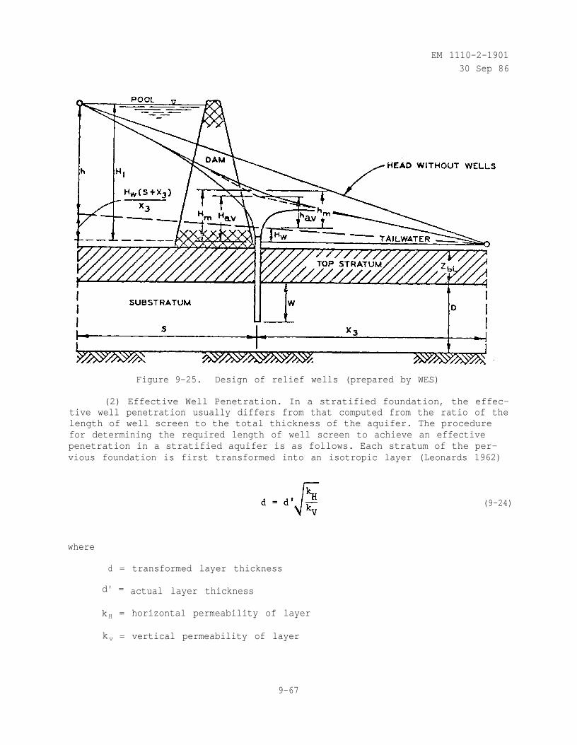
EM 1110-2-190130 Sep 86
Figure 9-25. Design of relief wells (prepared by WES)
(2) Effective Well Penetration. In a stratified foundation, the effec-tive well penetration usually differs from that computed from the ratio of thelength of well screen to the total thickness of the aquifer. The procedurefor determining the required length of well screen to achieve an effectivepenetration in a stratified aquifer is as follows. Each stratum of the per-vious foundation is first transformed into an isotropic layer (Leonards 1962)
where
d = transformed layer thickness
d' = actual layer thickness
kH = horizontal permeability of layer
kv = vertical permeability of layer
(9-24)
9-67
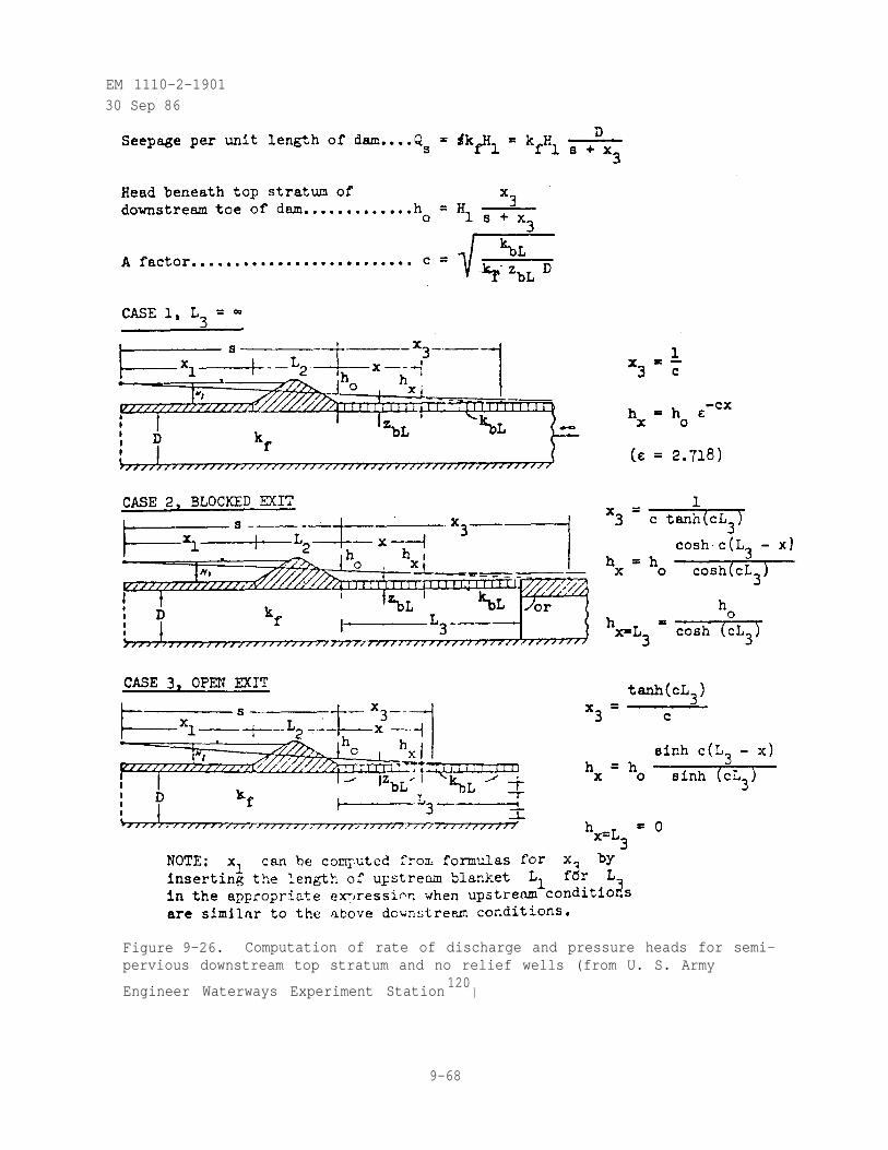
EM 1110-2-1901
30 Sep 86
Figure 9-26. Computation of rate of discharge and pressure heads for semi-pervious downstream top stratum and no relief wells (from U. S. Army
Engineer Waterways Experiment Station120
)
9-68
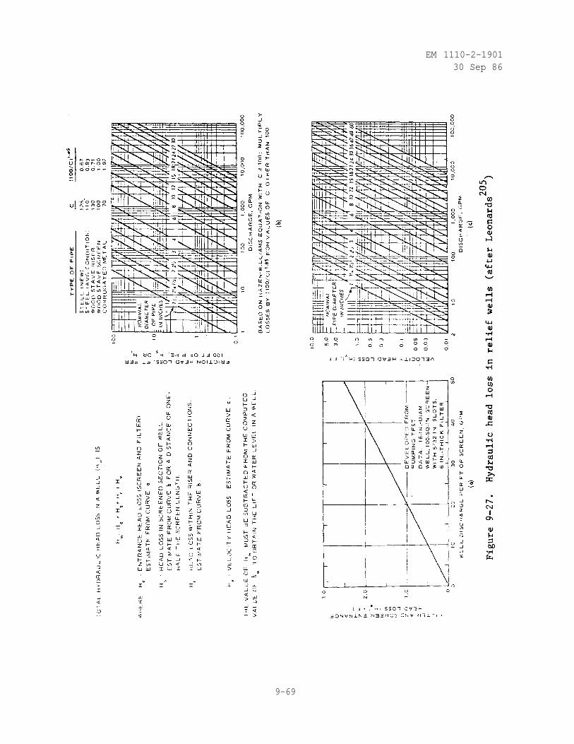
EM 1110-2-190130 Sep 86
9-69
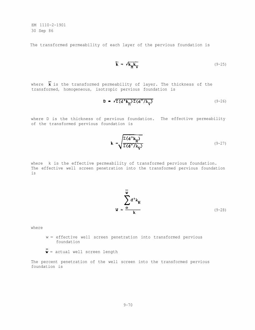
EM 1110-2-190130 Sep 86
The transformed permeability of each layer of the pervious foundation is
(9-25)
where is the transformed permeability of layer. The thickness of thetransformed, homogeneous, isotropic pervious foundation is
(9-26)
where D is the thickness of pervious foundation. The effective permeabilityof the transformed pervious foundation is
(9-27)
where k is the effective permeability of transformed pervious foundation.The effective well screen penetration into the transformed pervious foundationis
where
w = effective well screen penetration into transformed perviousfoundation
= actual well screen length
(9-28)
The percent penetration of the well screen into the transformed perviousfoundation is
9-70
EM 1110-2-1901
30 Sep 86
( 9 -29)
where is the actual pervious foundation thickness.
(3) Factor of Safety. The factor of safety against uplift or heavingat the downstream toe of the ham, based upon the critical gradient, is
(9-30)
where
Fh = factor of safety against uplift or heaving at the downstream toeof the dam
iCR = critical upward hydraulic gradient under the top stratum at thedownstream toe of the dam
iO = allowable upward hydraulic gradient under the top stratum at thedownstream toe of the dam
= submerged unit weight of downstream top stratum soil
ha = allowable pressure head under the top stratum at the downstreamtoe of the dam
ZbL = thickness of downstream top stratum
= unit weight of water
The factor of safety against uplift or heaving at the downstream toe of the dam
provided by the relief well system should be at least 1.5(1)
.
(4) Infinite and Finite Relief Well Systems. Formulas for the designof relief wells are based on the assumption that the flow is laminar,
(1) Relief wells should be designed to reduce the excess head to zero to pre-vent upward seepage from occurring beneath the downstream top stratum.
9-71
EM 1110-2-1901
30 Sep 86
artesian, and continuous and that a steady-state condition exists. Relief wellsystems are considered to be infinite or finite in length. The term infiniteis applied to a system of wells that conforms approximately to the followingidealized conditions:
(a) The wells are equally spaced and identical in dimensions.
(b) The pervious foundation is of uniform depth and permeability alongthe entire length of the system.
(c) The effective source of seepage and the effective line ofdownstream exit are parallel to the line of wells.
(d) The boundaries at the ends of the relief wells are impervious,normal to the line of wells, and at a distance equal to one-half the wellspacing beyond the end wells of the system.
If these conditions exist, the flow to each well and the pressure distributionaround each well are uniform for all wells along the line. Therefore, thereis no flow across planes centered between wells and normal to the line, henceno overall longitudinal component of flow exists anywhere in the system. Theterm infinite is applied to such a system because it may be analyzed mathe-matically by considering an infinite number of wells; the actual number ofwells in the system may be from one to infinity. Normally, a line of reliefwells below a dam extending entirely across a valley and terminating at rela-tively impervious valley walls should be designed as an infinite line. Afinite system of wells in any system that does not approximate the idealizedcondition for the infinite system. Whenever a major and abrupt change in thecharacter of the system such as penetration or well spacing might result inan appreciable component of flow parallel to the line of wells, the use ofdesign procedures for finite systems will be used (see U. S. Army Corps ofEngineers 1963).
(5) Drawdown to Infinite Line of Fully Penetrating Relief Wells withImpervious Top Stratum. Where the flow to an infinite line of fully pene-trating relief wells is from an infinite line source and the top stratum is
assumed to be completely impervious, (1) as shown in figure 9-28. The drawdownproduced by an equivalent continuous slot is
(9-31)
(1) Also applicable-when the top stratum is semipervious provided the wellsystem is located in a drainage ditch and the head is kept below theground surface on the downstream side of the dam to prevent any seepageupward through the top stratum. Under these conditions, the downstreamtop stratum acts as if it is impervious.
9-72
EM 1110-2-190130 Sep 86
where
H - he = drawdown produced by flow from continuous slot
Qw = discharge from equivalent continuous slot
L = distance from line source of seepage to wells
k = effective permeability of transformed pervious foundation
D = thickness of transformed pervious foundation
a = well spacing
However,This head
an additional head occurs because of converging flow at the wells.loss is a function of well flow, well spacing and penetration, well
radius, and thickness and permeability of the pervious foundation. For fullypenetrating wells
(9-32)
where
= head loss at well due to converging flow (see figure 9-28)
r w = effective radius of well (outside radius of well screen plusone-half of the thickness of the filter)
The total drawdown at the well, neglecting hydraulic head losses in the well,is that at the slot plus that due to the well
Substituting equations 9-31 and 9-32 into equation 9-33
(9-33)
(9-34)
9-73
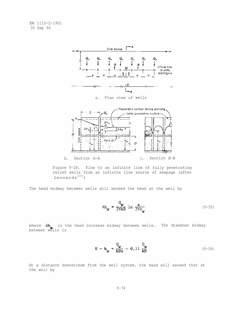
EM 1110-2-190130 Sep 86
a. Plan view of wells
b. Section A-A c. Section B-B
Figure 9-28. Flow to an infinite line of fully penetratingrelief wells from an infinite line source of seepage (afterLeonards205)
The head midway between wells will exceed the head at the well by
(9-35)
where is the head increase midway between wells.between wells is
The drawdown midway
(9-36)
At a distance downstream from the well system, the head will exceed that atthe well by
9-74
EM 1110-2-190130 Sep 86
where is the head increase downstream
of the wells is
of wells. The drawdown downstream
(9-37)
(9-38)
(6) Drawdown to Infinite Line of Partially Penetrating Relief Wellswith Impervious Top Stratum. For an infinite line of partially penetratingrelief wells where the flow is from an infinite line source and the top stratumis assumed to be impervious (or semipervious as previously described) the headloss at the partially penetrating well due to converging flow is
(9-39)
where is the average uplift factor (obtained from figure 9-29). The
total drawdown at the partially penetrating well, neglecting hydraulic headlosses in the well, is that at the slot plus that due to the well
(9-40)
The head midway between partially penetrating wells will exceed the head atthe well by
(9-41)
where
is the midpoint uplift factor (obtained from figure 9-29). The draw-
down midway between partially penetrating wells is
(9-42)
9-75
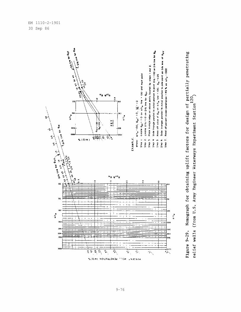
EM 1110-2-190130 Sep 86
9-76
EM 1110-2-190130 Sep 86
(7) Drawdown to Infinite Line of Relief Wells with Semipervious TopStratum. Where the top stratum is semipervious, the need for relief wells isevaluated by determining the piezometric grade line without relief wells usingblanket formulas given in figure 9-26. As stated previously, the factor ofsafety against uplift or heaving at the downstream toe of the dam, as deter-mined from equation 9-30, should be at least 1.5. If relief wells arerequired, the spacing for an infinite line of relief wells for a given pene-tration is determined using a procedure of successive trials and the nomographgiven in figure 9-29. The required well spacing is affected by hydraulic headlosses in the well which are estimated from figure 9-27. The procedure forcomputing the well spacing is as follows:
(a) Compute the allowable pressure head under the top stratum at thedownstream toe of the dam from
(9-43)
where
ha = allowable pressure head under the top stratum at the downstreamtoe of the dam
= submerged unit weight of downstream top stratum soil
Zbl = thickness of downstream top stratum
= unit weight of water
Fh = factor of safety against uplift or heaving at the downstream toeof the dam
(b) Assume that the net head in the plane of the wells equals theallowable pressure head under the top stratum at the downstream toe of the damand compute the net seepage gradient toward the well line
where
net seepage gradient toward the well line
h = net head acting on the dam
Havg = net head in the plane of the wells
9-77
(9-44)
EM 1110-2-1901
30 Sep 86
S = distance from line of relief wells to effective source of seepageentry (see procedure in U. S. Army Engineer Waterways ExperimentStation 1956a)
X3= distance from line of relief wells to effective seepage exit (see
procedure in figure 9-26)
Setting Havg = ha in equation 9-44 gives
(9-45)
(c) Assume a well spacing and compute the flow from a single well
where
(9-46)
Qw = flow from a single well
kf = effective permeability of transformed pervious foundation
D = transformed thickness of pervious foundation
a = well spacing
= average uplift factor (obtained from figure 9-29)
(d) Estimate the total hydraulic head loss in the well fromfigure 9-27.
(e) Compute the net average head in the plane of wells above the totalhead loss in the well including elevation head loss (see figure 9-25) from
(9-47)
where
havg = net average head in the plane of wells above the total head lossin the well including elevation head loss
9-78
EM 1110-2-1901
30 Sep 86
Ha v g = net head in the plane of wells
H W = total head loss in the well including elevation head loss
(f) Substitute values obtained from and ha v g from equation 9-45
and 9-47, respectively, and solve for the average uplift factor
(9-48)
where is the average uplift factor.
(g) Find from figure 9-29 using the values of a used in
equation 9-48 and the corresponding a/rw and D/a values.
(h) The first trial well spacing is that of value a for whichfrom step (f) equals from step (g).
(i) Find from figure 9-29 for the first trial well spacing and thecorresponding values of a/rw and D/a .
(j) If repeat steps (c) to (i) using the first trial well
spacing in lieu of the spacing originally used in step (c), and determine thesecond trial well spacing. This procedure should be repeated until relativelyconsistent values of a are obtained on two successive trials. Usually thesecond trial spacing is sufficiently accurate.
If in step (j), a modified procedure is used for the second trial:
(k) Assume Hm = ha and compute QW from equation 9-46 using the
value of AM obtained in step (b) and the first trial well spacing fromstep (h).
(1) Estimate Hw from Qw of step (k) and figure 9-27.
(m) Compute the net head beneath the top stratum midway between thewells above the total head loss in the well including elevation head loss (seefigure 9-25) from
(9-49)
where
hm = net head beneath the top stratum midway between the wells above thetotal head loss in the well including elevation head loss
9-79
EM 1110-2-1901
30 Sep 86
Hm= net head beneath the top stratum midway between the wells
HW= total head loss in the well including elevation head loss
h(n) Using from steps (h) and (i), respectively, computefroma v g
(9-50)
where h a v g is the net head in the plane of wells.
(o) Using Hw and h from steps (1) and (n), respectively, andcompute H from
a v g
a v g
(9-51)
(p) Compute from equation 9-44 using Ha v g from step (o).
(q) Using hm and from steps (m) and (p), respectively, computefor various values of a from
(9-52)
where is the midpoint uplift factor.
(r) Find from figure 9-29 for the values of a used in step (q)
and the corresponding a/r and D/a values.w
(s) The second trial well spacing is that value of a which fromstep (q) equals from step (r).
(t) Find from figure 9-29 for the second trial well spacing and
the corresponding values of a/rw and D/a .
(u) Determine the third trial well spacing by repeating steps (k) to(t) using the second trial well spacing in lieu of the spacing originallyassumed in step (k), and in step (n) using the values of and from
steps (s) and (t), respectively, instead of those from steps (h) and (i). Thisprocedure should be repeated until relatively consistent values of a areobtained on two successive trials. Normally, the third trial is sufficientlyaccurate.
9-80
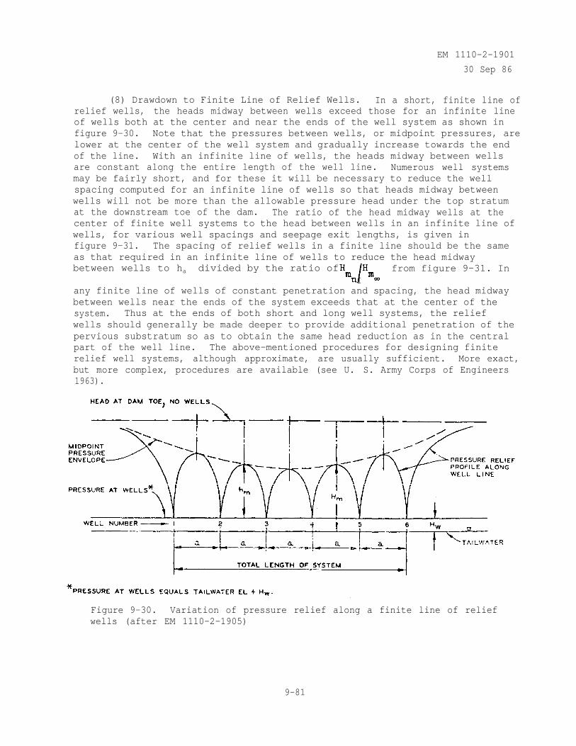
EM 1110-2-1901
30 Sep 86
(8) Drawdown to Finite Line of Relief Wells. In a short, finite line ofrelief wells, the heads midway between wells exceed those for an infinite lineof wells both at the center and near the ends of the well system as shown infigure 9-30. Note that the pressures between wells, or midpoint pressures, arelower at the center of the well system and gradually increase towards the endof the line. With an infinite line of wells, the heads midway between wellsare constant along the entire length of the well line. Numerous well systemsmay be fairly short, and for these it will be necessary to reduce the wellspacing computed for an infinite line of wells so that heads midway betweenwells will not be more than the allowable pressure head under the top stratumat the downstream toe of the dam. The ratio of the head midway wells at thecenter of finite well systems to the head between wells in an infinite line ofwells, for various well spacings and seepage exit lengths, is given infigure 9-31. The spacing of relief wells in a finite line should be the sameas that required in an infinite line of wells to reduce the head midwaybetween wells to ha divided by the ratio of
Ifrom figure 9-31. In
any finite line of wells of constant penetration and spacing, the head midwaybetween wells near the ends of the system exceeds that at the center of thesystem. Thus at the ends of both short and long well systems, the reliefwells should generally be made deeper to provide additional penetration of thepervious substratum so as to obtain the same head reduction as in the centralpart of the well line. The above-mentioned procedures for designing finiterelief well systems, although approximate, are usually sufficient. More exact,but more complex, procedures are available (see U. S. Army Corps of Engineers1963).
Figure 9-30. Variation of pressure relief along a finite line of reliefwells (after EM 1110-2-1905)
9-81
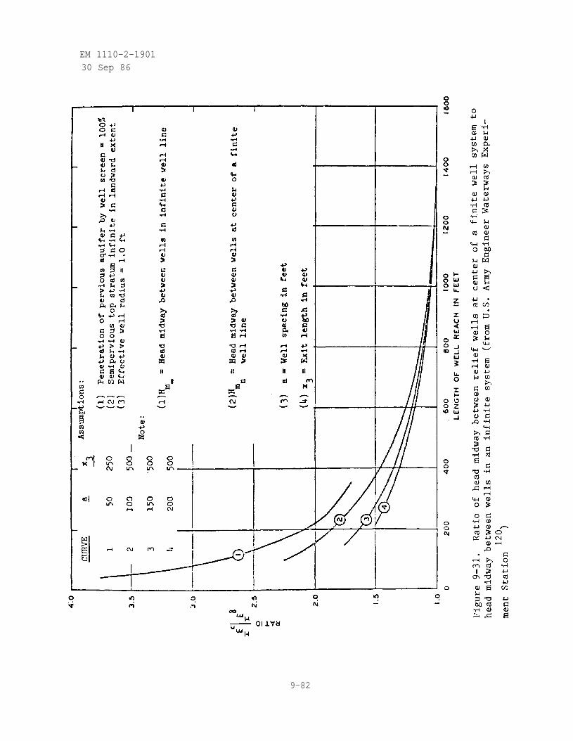
EM 1110-2-190130 Sep 86
9-82
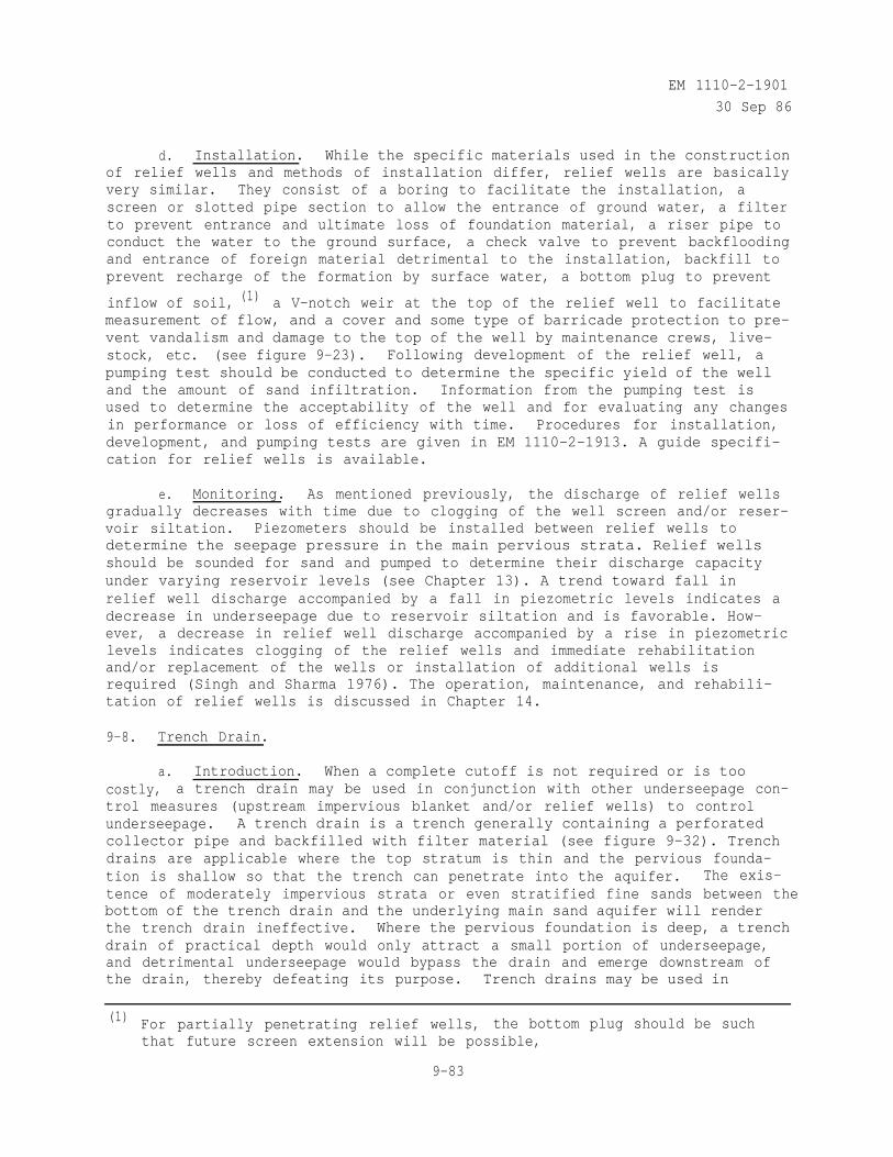
EM 1110-2-1901
30 Sep 86
d. Installation. While the specific materials used in the constructionof relief wells and methods of installation differ, relief wells are basicallyvery similar. They consist of a boring to facilitate the installation, ascreen or slotted pipe section to allow the entrance of ground water, a filterto prevent entrance and ultimate loss of foundation material, a riser pipe toconduct the water to the ground surface, a check valve to prevent backfloodingand entrance of foreign material detrimental to the installation, backfill toprevent recharge of the formation by surface water, a bottom plug to prevent
inflow of soil, (1) a V-notch weir at the top of the relief well to facilitatemeasurement of flow, and a cover and some type of barricade protection to pre-vent vandalism and damage to the top of the well by maintenance crews, live-stock, etc. (see figure 9-23). Following development of the relief well, apumping test should be conducted to determine the specific yield of the welland the amount of sand infiltration. Information from the pumping test isused to determine the acceptability of the well and for evaluating any changesin performance or loss of efficiency with time. Procedures for installation,development, and pumping tests are given in EM 1110-2-1913. A guide specifi-cation for relief wells is available.
e. Monitoring. As mentioned previously, the discharge of relief wellsgradually decreases with time due to clogging of the well screen and/or reser-voir siltation. Piezometers should be installed between relief wells todetermine the seepage pressure in the main pervious strata. Relief wellsshould be sounded for sand and pumped to determine their discharge capacityunder varying reservoir levels (see Chapter 13). A trend toward fall inrelief well discharge accompanied by a fall in piezometric levels indicates adecrease in underseepage due to reservoir siltation and is favorable. How-ever, a decrease in relief well discharge accompanied by a rise in piezometriclevels indicates clogging of the relief wells and immediate rehabilitationand/or replacement of the wells or installation of additional wells isrequired (Singh and Sharma 1976). The operation, maintenance, and rehabili-tation of relief wells is discussed in Chapter 14.
9-8. Trench Drain.
a. Introduction. When a complete cutoff is not required or is toocostly, a trench drain may be used in conjunction with other underseepage con-trol measures (upstream impervious blanket and/or relief wells) to controlunderseepage. A trench drain is a trench generally containing a perforatedcollector pipe and backfilled with filter material (see figure 9-32). Trenchdrains are applicable where the top stratum is thin and the pervious founda-tion is shallow so that the trench can penetrate into the aquifer. The exis-tence of moderately impervious strata or even stratified fine sands between thebottom of the trench drain and the underlying main sand aquifer will renderthe trench drain ineffective. Where the pervious foundation is deep, a trenchdrain of practical depth would only attract a small portion of underseepage,and detrimental underseepage would bypass the drain and emerge downstream ofthe drain, thereby defeating its purpose. Trench drains may be used in
(1) For partially penetrating relief wells, the bottom plug should be suchthat future screen extension will be possible,
9-83
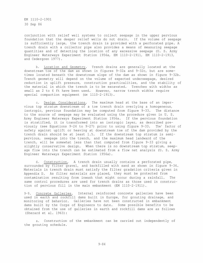
EM 1110-2-1901
30 Sep 86
conjunction with relief well systems to collect seepage in the upper perviousfoundation that the deeper relief wells do not drain. If the volume of seepageis sufficiently large, the trench drain is provided with a perforated pipe. Atrench drain with a collector pipe also provides a means of measuring seepagequantities and of detecting the location of any excessive seepage (U. S. ArmyEngineer Waterways Experiment Station 1956a, EM 1110-2-1911, EM 1110-2-1913,and Cedergren 1977).
b. Location and Geometry. Trench drains are generally located at thedownstream toe of the dam as shown in figures 9-32a and 9-32c, but are some-times located beneath the downstream slope of the dam as shown in figure 9-32b.Trench geometry will depend on the volume of expected underseepage, desiredreduction in uplift pressure, construction practicalities, and the stability ofthe material in which the trench is to be excavated. Trenches with widths assmall as 2 to 6 ft have been used. However, narrow trench widths requirespecial compaction equipment (EM 1110-2-1913).
c. Design Considerations. The maximum head at the base of an imper-vious top stratum downstream of a toe trench drain overlying a homogeneous,isotropic, pervious foundation may be computed from figure 9-33. The distanceto the source of seepage may be evaluated using the procedure given in U. S.Army Engineer Waterways Experiment Station 1956a. If the pervious foundationis stratified, it is transformed into an isotropic layer, as described pre-viously (see Equations 9-24 to 9-27) prior to using figure 9-33. The' factor ofsafety against uplift or heaving at downstream toe of the dam provided by thetrench drain should be at least 1.5. If the downstream top stratum is semi-pervious, seepage into the trench, and the maximum head landward of thetrench, will be somewhat less than that computed from figure 9-33 giving aslightly conservative design. When there is no downstream top stratum, seep-age flow into the trench can be estimated from a flow net analysis (U. S. ArmyEngineer Waterways Experiment Station 1956a).
d. Construction. A trench drain usually contains a perforated pipe,surrounded by filter gravel, and backfilled with sand as shown in figure 9-34.Materials in trench drain must satisfy the filter gradation criteria given inAppendix D. As filter materials are placed, they must be protected fromcontamination resulting from inwash that might occur during a rainfall. Thesame control procedures are used for trench drains as those used in construc-tion of pervious fill in the main embankment (EM 1110-2-1911).
9-9. Concrete Galleries. Internal reinforced concrete galleries have beenused in earth and rockfill dams built in Europe, for grouting drainage, andmonitoring of behavior. Galleries have not been constructed in embankmentdams built by the Corps of Engineers to date. Some possible benefits to beobtained from the use of galleries in earth and rockfill dams are as follows(Sherard et al. 1963):
a. Construction of the embankment can be carried out independently ofthe grouting schedule.
9-84
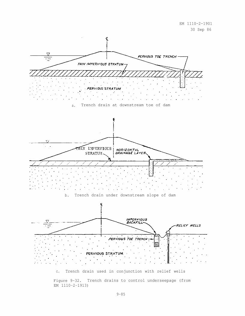
EM 1110-2-1901
30 Sep 86
a. Trench drain at downstream toe of dam
b. Trench drain under downstream slope of dam
c. Trench drain used in conjunction with relief wells
Figure 9-32. Trench drains to control underseepage (fromEM 1110-2-1913)
9-85
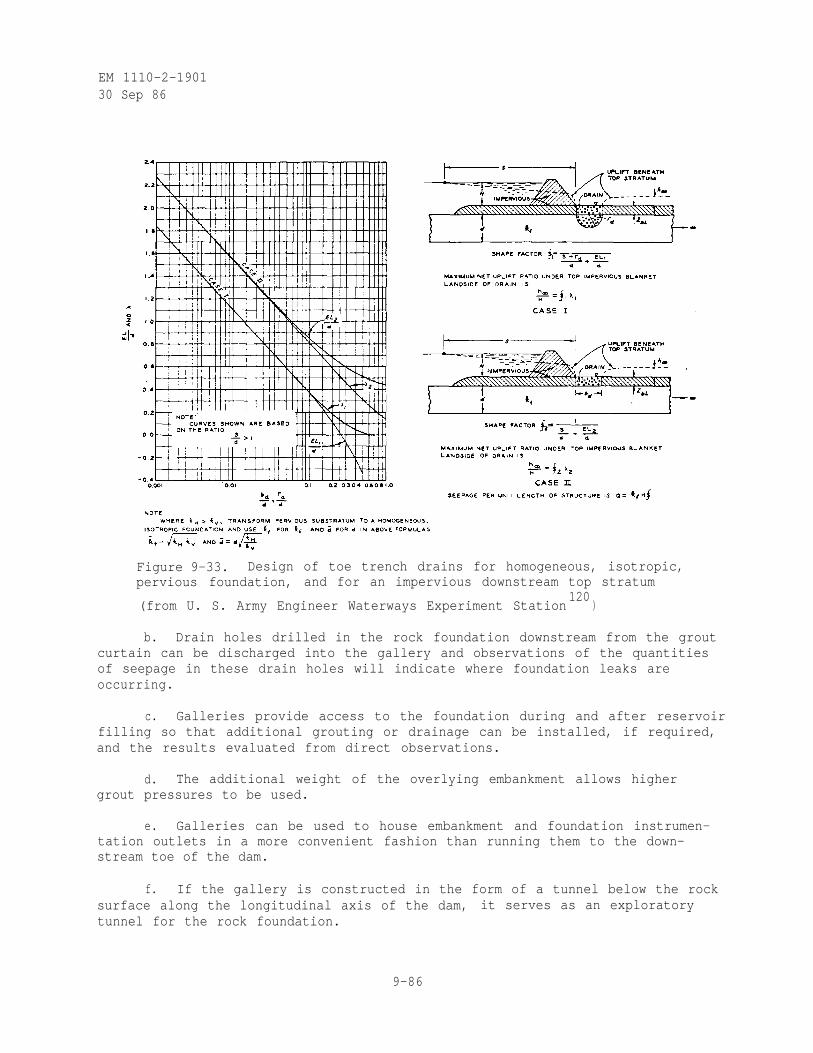
EM 1110-2-190130 Sep 86
Figure 9-33. Design of toe trench drains for homogeneous, isotropic,pervious foundation, and for an impervious downstream top stratum
(from U. S. Army Engineer Waterways Experiment Station120
)
b. Drain holes drilled in the rock foundation downstream from the groutcurtain can be discharged into the gallery and observations of the quantitiesof seepage in these drain holes will indicate where foundation leaks areoccurring.
c. Galleries provide access to the foundation during and after reservoirfilling so that additional grouting or drainage can be installed, if required,and the results evaluated from direct observations.
d. The additional weight of the overlying embankment allows highergrout pressures to be used.
e. Galleries can be used to house embankment and foundation instrumen-tation outlets in a more convenient fashion than running them to the down-stream toe of the dam.
f. If the gallery is constructed in the form of a tunnel below the rocksurface along the longitudinal axis of the dam, it serves as an exploratorytunnel for the rock foundation.
9-86
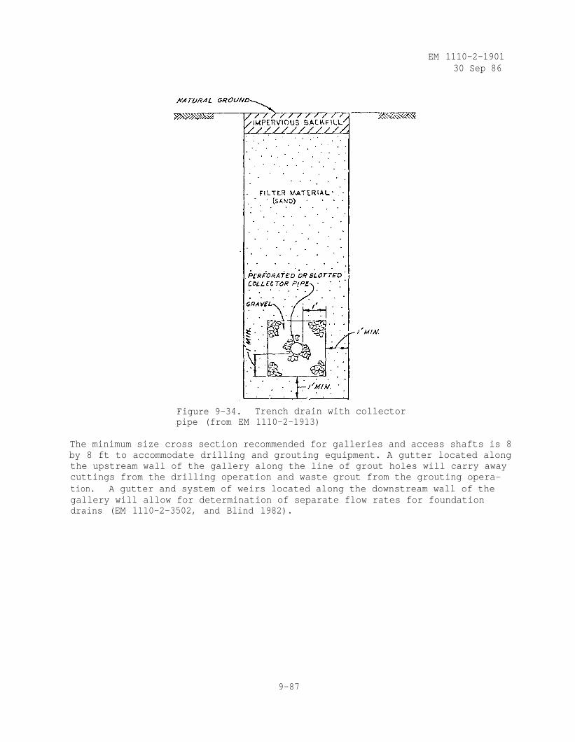
EM 1110-2-190130 Sep 86
Figure 9-34. Trench drain with collectorpipe (from EM 1110-2-1913)
The minimum size cross section recommended for galleries and access shafts is 8by 8 ft to accommodate drilling and grouting equipment. A gutter located alongthe upstream wall of the gallery along the line of grout holes will carry awaycuttings from the drilling operation and waste grout from the grouting opera-tion. A gutter and system of weirs located along the downstream wall of thegallery will allow for determination of separate flow rates for foundationdrains (EM 1110-2-3502, and Blind 1982).
9-87
EM 1110-2-1901
30 Sep 86
CHAPTER 10SEEPAGE CONTROL THROUGH EARTH ABUTMENTS ADJACENT TO STRUCTURES
AND BENEATH SPILLWAYS AND STILLING BASINS
10-1. Through Earth Abutments. Earth and rock-fill dams, particularly inglaciated regions, may have pervious material, resulting from filling of thepreglacial valley with alluvial or morainal deposits followed by the down-cutting of the stream, in one or both abutments (Twelker 1957). Seepagethrough the pervious abutment(s) is combined with through seepage and under-seepage to determine the total seepage loss. As mentioned previously, the pur-pose of the project, i.e., long-term storage, flood control, hydropower, etc.,will determine the allowable seepage loss. Seepage control through earthabutments is provided by extending the upstream impervious blanket in thelateral direction to wrap around the abutment up to the maximum water surfaceelevation, by placing a filter layer between the pervious abutment and the damdownstream of the impervious core section, and, if necessary, by installingrelief wells at the downstream toe of the pervious abutment. At the NorthBranch of Kokosing Dam, Ohio, the left abutment is an outwash terrace consist-ing of sands and gravels with layers of silt and clay as shown in figure 10-1.Seepage control through the pervious abutment was provided by a 5-ft-thickimpervious upstream blanket which wrapped around the left abutment, a filterlayer between the pervious abutment and the dam downstream of the imperviouscore (see figure 10-2), and three fully penetrating relief wells at the down-stream toe of the pervious abutment (U. S. Army Engineer District, Huntington1969).
10-2. Adjacent to Outlet Conduits. When the dam foundation consists of com-pressible soils, the outlet works tower and conduit should be founded upon orin stronger abutment soils or rock. When conduits are laid in excavatedtrenches in soil foundations, concrete seepage cutoff collars shall not beprovided solely for the purpose of increasing seepage resistance since theirpresence often results in poorly compacted backfill around the conduit. Col-lars, with a minimum projection from the conduit surface, will be used overconduit joints to protect against joint displacements resulting from differen-tial movement on yielding foundations. Excavations for outlet conduits insoil foundations shall be wide enough to allow for backfill compactionparallel to the conduit using heavy rolling compaction equipment. Equipmentused to compact along the conduit should be free of framing that prevents itsload transferring wheels or drum from working against the structure. Excavatedslopes in soil for conduits should be no steeper than 1V to 2H to facilitateadequate compaction and bonding of backfill with the sides of the excavation.Drainage layers should be provided around the conduit in the downstream zone ofembankments without pervious shells. A concrete plug shall be used as backfillin rock cuts for cut-and-cover conduits within the core zone to ensure a water-tight bond between the conduit and vertical rock surfaces. The plug, which canbe constructed of lean concrete, should be at least 50 ft long and extend up tothe original rock surface. In embankments having a random or an imperviousdownstream shell, horizontal drainage layers should be placed along the sidesand over the top of conduits downstream of the impervious core. Where outletstructures are to be located in active seismic areas, special attention must begiven to the possibility of movement along-existing or possibly new faults(EM 1110-2-2300).
10-1
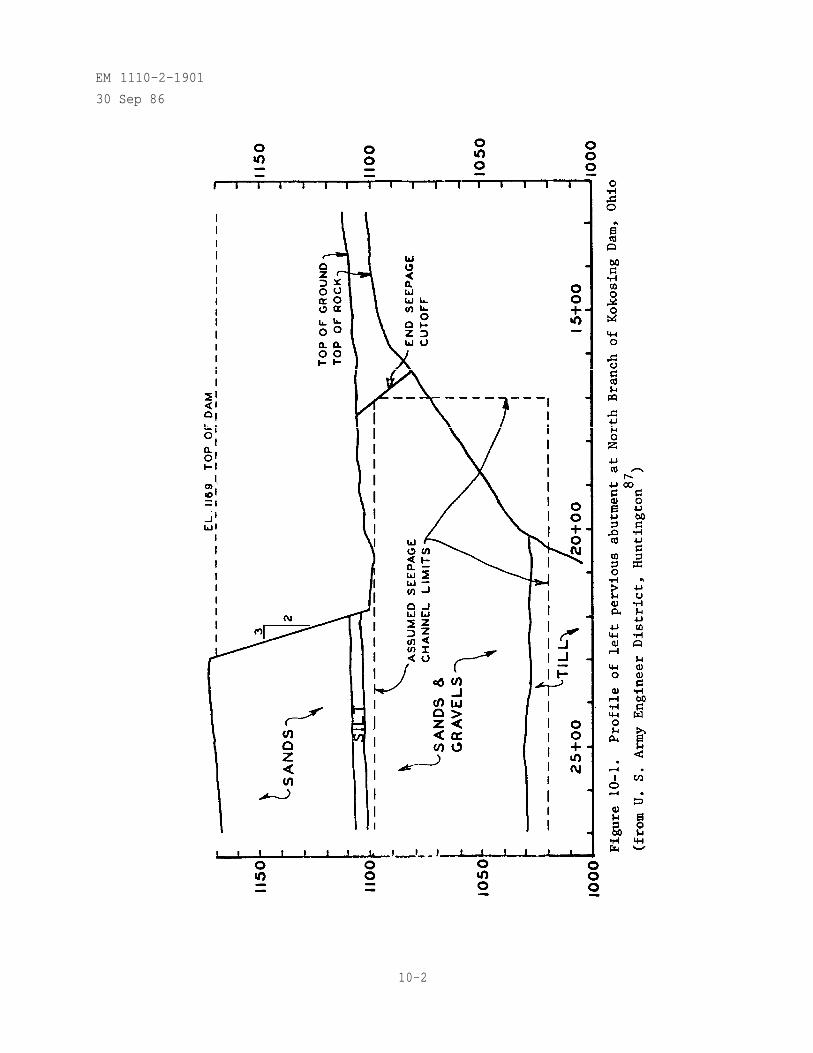
EM 1110-2-1901
30 Sep 86
10-2
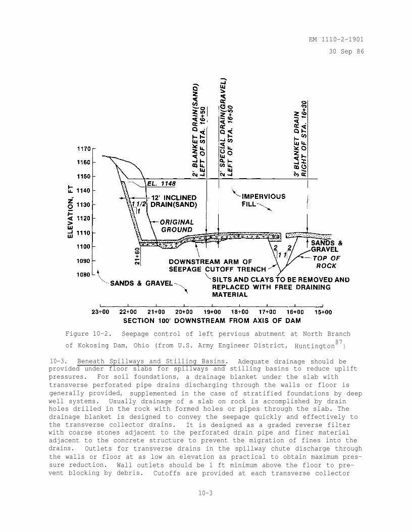
EM 1110-2-1901
30 Sep 86
Figure 10-2. Seepage control of left pervious abutment at North Branch
of Kokosing Dam, Ohio (from U.S. Army Engineer District, Huntington87
)
10-3. Beneath Spillways and Stilling Basins. Adequate drainage should beprovided under floor slabs for spillways and stilling basins to reduce upliftpressures. For soil foundations, a drainage blanket under the slab withtransverse perforated pipe drains discharging through the walls or floor isgenerally provided, supplemented in the case of stratified foundations by deepwell systems. Usually drainage of a slab on rock is accomplished by drainholes drilled in the rock with formed holes or pipes through the slab. Thedrainage blanket is designed to convey the seepage quickly and effectively tothe transverse collector drains. It is designed as a graded reverse filterwith coarse stones adjacent to the perforated drain pipe and finer materialadjacent to the concrete structure to prevent the migration of fines into thedrains. Outlets for transverse drains in the spillway chute discharge throughthe walls or floor at as low an elevation as practical to obtain maximum pres-sure reduction. Wall outlets should be 1 ft minimum above the floor to pre-vent blocking by debris. Cutoffs are provided at each transverse collector
10-3
EM 1110-2-1901
30 Sep 86
pipe to minimize buildup of head in case of malfunction of the pipe drain.Drains should be at least 6 in. in diameter and have at least two outlets tominimize the chance of plugging. Outlets should be provided with flat-typecheck valves to prevent surging and the entrance of foreign matter in thedrainage system. For the stilling basin floor slab, it may be advantageous toplace a connecting header along each wall and discharge all slab drainage intothe stilling basin just upstream from the hydraulic jump at the lowest practi-cal elevation, in order to secure the maximum reduction of uplift for thedownstream portion of the slab. A closer spacing of drains is usuallyrequired than in the spillway chute because of greater head and considerabledifference in water depth in a short distance through the hydraulic jump.Piezometers should be installed in the drainage blanket and deeper strata, ifnecessary, to monitor the performance of the drainage systems. If the drainsor wells become plugged or otherwise noneffective, uplift pressures willincrease which could adversely affect the stability of the structure(EM 1110-2-2400 and EM 1110-2-2300).
10-4
EM 1110-2-1901
30 Sep 86
CHAPTER 11SEEPAGE CONTROL IN ROCK FOUNDATIONS AND ABUTMENTS
11-1. General Considerations.
a. The choice of seepage control methods to use in rock foundations andabutments is dependent on a number of factors. Characterization of the founda-tion or abutment and identification of potential seepage paths is essential.Before any method of seepage control is implemented, the area must bethoroughly explored and tested to assure that the method chosen will apply tothe general conditions as well as the conditions locally encountered and willserve the intended purpose. In many cases, a combination of methods can beused to the best advantage for rock foundations or abutments. The use of dif-ferent control methods becomes particularly important when there is a change inthe character of the foundation from one location to another, or a change inseepage characteristics between the foundation and the abutment.
b. Seepage should be cut off or controlled by drainage whenever economi-cally possible. Safety, however, must be the governing factor for selecting aseepage control method. It should be noted that the possibility exists forcontrol measures to cause substantial increases in seepage rather thandecreases. Such increases are normally accompanied by reductions in upliftpressures and are therefore desirable if the increased seepage produces nodetrimental side effects. In the final choice of a seepage control method, ormethods, economic factors must be recognized and evaluated.
11-2. Cutoff Trenches.
a. No cutoff is 100 percent impervious and therefore the reduction inseepage from cutoff trenches is a relative matter. Cutoff trenches are nor-mally employed where the character of the foundation is such that the con-struction of a satisfactory or effective grout curtain is not practical. Suchtrenches, when constructed, are normally backfilled with compacted imperviousmaterial, bentonite slurry, or neat cement.
b. Construction of trenches in rock foundations and abutments normallyinvolves blasting using the presplit method with primary holes deck-loadedaccording to actual foundation conditions. After blasting, excavation is nor-mally accomplished with a backhoe. Cutoff of seepage within the foundation isobtained by connecting an impervious portion of the foundation to the imper-vious portion of the structure by backfilling the trench with an imperviousmaterial. In rock foundations, as in earth foundations, the impervious layerof the foundation, in some cases, may be sandwiched between an upper and alower pervious layer, and a cutoff to such as impervious layer would reduceseepage only through the upper pervious layer. However, where the thicknessesof the impervious and upper pervious are sufficient, the layers may be able toresist the upward seepage pressures existing in the lower pervious layer andthus remain stable. Cutoff of seepage within the abutment is normallyobtained by extending the cutoff from above the projected seepage line to animpervious layer within the abutment. The type of backfill material is nor-mally dictated by condition of the foundation or abutment, economics, anddegree of cutoff required.
11-1
EM 1110-2-1901
30 Sep 86
11-3. Abutment Impervious Blankets.
a. Impervious blankets overlying the upstream or riverside face of per-vious abutments, or foundations, are effective in reducing the quantity ofseepage and to some extent will reduce uplift pressures and gradients down-stream. An impervious blanket may be used for earthen or rock abutments;however, a filter material is normally required with rock abutments.
b. The construction of impervious blankets is particularly adaptable totreating exposed pervious areas of abutments which are adjacent to the mainstructure. In cases where a natural impervious blanket exists on the abutment,ranging in depth from a few feet to many feet, full advantage should be takenof the existing material. Upstream borrow along the abutment should be con-trolled to prevent excessive excavation of the natural impervious top blanket.Conversely, localized areas which are thin and weak should be reinforced bythe addition of additional impervious material.
c. Blankets may sometimes give adequate control of seepage water for lowhead structures, but for high head structures it is usually necessary to incor-porate a downstream drainage system as a part of the overall seepage-controldesign. The benefits derived from abutment impervious blankets are due to thedissipation of a part of the reservoir head through the blanket. The propor-tion of head dissipated is dependent upon the thickness, length, and effectivepermeability of the blanket in relation to the permeability of the adjacentsoil, or rock.
11-4. Drainage and Grouting Galleries and Tunnels.
a. Foundation galleries and tunnels in concrete gravity dams provide anexit for foundation drains and convenient facilities for rehabilitation work,or supplemental grouting, if required. The depth of drainage galleries, orexit elevation of the drains, with respect to the tailwater, controls theuplift downstream of the drains or wells. Generally, the lower the elevationof the gallery, the more reduction in head, or uplift, is experienced. If thedepth of the drainage gallery is located and the gallery discharges at theelevation of the tailwater, the magnitude of the uplift downstream of the wellsis normally very modest. The uplift, however, is controlled by well spacing,well efficiency, and other seepage control measures, such as grout curtains andcutoffs, in addition to the elevation of the drainage gallery and the elevationat which it discharges. In special cases where the drainage gallery is verydeep, i.e., below tailwater, it is possible to actually create a negative up-lift on the base of a dam. In such cases some of the seepage pumped from thedrainage gallery flows through the foundation to the drains from downstream.
b. Grouting curtains are frequently centered along drainage galleries ortunnels. Remedial or supplemental' grouting may be performed from withindrainage tunnels. The additional grouting may be performed vertically or ininclined, or sloping, boreholes. Also, should excessive uplift pressuresbecome evident, additional grouting to widen or deepen the curtain may beperformed or additional drainage wells may be installed from the gallery torelieve excess pressures.
11-2
EM 1110-2-1901
30 Sep 86
11-5. Grouting of Foundations and Abutments.
a. The Corps‘ grouting methods have become less standardized in recentyears (Albritton, Jackson, and Banget 1984). Typically, however, a combinationof a line of drainage holes and a grout curtain provide an efficient and effec-tive seepage control method. A properly installed grout curtain in the founda-tion of a structure not only provides a substantial reduction in seepage butalso reduces the uplift pressures downstream of the curtain. Conveniently, forthe great majority of dam sites, irrespective of type of rock, strike and dipof strata, and faulting conditions, the pervious zone which requires seepagecontrol is relatively shallow and lends itself readily to control by grouting.A comprehensive coverage of drilling methods, as well as grouting methods, ispresented in EM 1110-2-3506.
b. Grouting operations in foundations and abutments are not limited toconstruction of grout curtains. Grouting may be used for foundation repair andfilling cavities or voids in limestone or carbonate formations. The require-ment for a single- or multiple-line grout curtain is dictated by the conditionand integrity of the foundation as determined from preconstruction exploration.
c. Grouting of steep abutment slopes has the potential for causing dif-ficulties and possibly can do more harm than good. Care must be exercised whengrouting in abutments to avoid displacements within the rock mass. Even rela-tive low grouting pressures can cause joint opening and decrease the integrityof the abutment.
d. In general the efficiency of a grouting operation for controllingseepage in well graded sediments is proportional to the width of the curtain.In rock foundations and abutments the seepage control accomplished by groutingis not a function of width, however, but is dictated by the effectiveness ofsealing seepage paths and open joints identified in the exploration program.The effectiveness of a grouting operation may be evaluated by pre- and post-grouting pressure injection tests for evaluating the water take and the foun-dation or abutment permeability.
11-6. Surface Treatment of Foundations and Abutments.
a. Surface treatment of foundations and abutments is essential to ensureintimate contact of backfill materials with sound rock. Once a foundation isexposed by excavation, the method of treatment and potential protection againstpiping of embankment or abutment materials will be dictated by the conditionsencountered. All cavities, or caves, should be cleaned and plugged with con-crete, both upstream and downstream from the core trench. All openings, fis-sures, joints, etc., should be cleaned after excavation and treated with dentalconcrete, where possible. Treatment with dental concrete stops major deterio-ration of materials that weather rapidly during construction, and helps toprevent lateral piping of the embankment material into the adjacent foundation.
b. If a well-developed, highly solutioned joint system, or similar con-dition is encountered in the abutment, thick concrete walls may be placedagainst the abutment. Prior to placement of concrete walls the abutment facemust be set back and cleaned, with presplitting being occasionally required.
11-3

EM 1110-2-1901
30 Sep 86
Concrete walls offer the advantage of either filling or blocking cavities,affording a reasonable condition for treatment by grouting, and provide anabutment "tie-in" for fill placement with ideal conditions for maximum compac-tion of the adjacent embankment.
11-4
EM 1110-2-1901
30 Sep 86
CHAPTER 12REMEDIAL SEEPAGE CONTROL
12-1. General Considerations. This chapter assumes that a seepage problemwith an existing structure has been identified and defined by methods dis-cussed in Chapter 13, or by other observations. The next step is to decide ona remedy, design and install the remedial measure, and monitor its performanceto determine if the problem has been satisfactorily addressed. Several fac-tors, including consequences of continued detrimental seepage, the geotechnicalenvironment (embankment, foundation, abutment), and economy, will determine thetype and degree of remedial seepage control. Some of the more critical conse-quences include:
a. Breaching of the embankment or loss of support to structural membersdue to piping.
b. Breaching of the embankment from slope instability induced by loss ofmaterial and/or strength due to seepage.
c. Loss of significant amounts of reservoir water.
d. Maintenance problems or loss of useful areas due to seepage on thedownstream slope or areas downstream of the embankment.
12-2. Remedial Methods.
a. Factors Affecting Choice of Methods, Several methods of reducingundesirable seepage are discussed in this chapter; most have been previouslyaddressed in Chapters 8-11, which described methods and appropriate settingsfor each. The remedial designer, while possibly having more advanced technol-ogy available than the original designer, must work with existing conditions.The embankment and its foundation, abutments, and seepage control measures mayform a complicated structure through which seepage occurs. This can make pre-cise detection and remedial control difficult or impossible. Remedial actionmay range from continued or additional monitoring to rebuilding or abandonmentof the dam. Choice of remedial method(s) will depend on several factors, whichinclude:
(1) Geotechnical environment.
(2) Risk.
(3) Degree of correction required.
(4) cost.
b. Effects of Methods on Other Structure Elements. The remedialdesigner must also consider the interplay of the remedial measures with otherdam elements. For example:
(1) Effect of excavation for drains, cutoff trenches, slurry trenches,etc., on embankment stability.
12-1
EM 1110-2-1901
30 Sep 86
(2) Difficulty of tying remedial measure to existing seepage controlelements.
(3) Possibility of hydraulic fracturing when grouting.
c. Monitoring. In all cases, pre- and post-remedial monitoring of seep-age is essential to determine the effectiveness of remedial action. SinceChapters 8-11 describe control measures in detail, this chapter will just pointout primary considerations in the choice of remedial measures and give examplesof their use. These examples are provided for general guidance only, sinceefficient use of remedial measures is very dependent upon geotechnical charac-teristics of the particular site's as-built configuration, reservoir uses, andpool history.
12-3. Storage Restriction. The most direct method to alleviate a seepageproblem is to lower the reservoir and restrict pool levels in order to stop orreduce seepage and its effects. This is often done during problem identifica-tion. If piezometer and seepage quantity measurement devices are in place atthis time, the effect of this remedy will be experimentally determined.Considerations in storage reduction include:
a. Reduction of downstream inundation area and level should breachingoccur.
b. Effects of pool lowering on water supply, flood control, power gen-eration, navigation, recreation, and environment.
Normally, lowering and restriction of the reservoir pool is not an acceptablelong-term solution, but this depends on restriction levels and purpose of thereservoir. Care must be taken in lowering the reservoir since rapid drawdowncan lead to instability of the upstream slope. Of course, risk of upstreamslope failure would normally be a preferred alternative to breaching of the damand release of a full reservoir.
12-4. Grouting. Grouting is a common, long-used remedy for seepage. Itseffectiveness is dependent upon being able to rather specifically locate theleaking area and fill the culprit openings without damage to the embankment.Possible damage includes cracking of impermeable cores or other impermeableareas of the embankment, foundation, or abutments, and clogging of drains. Ifgrouting results in sealing of the foundation just downstream of or beneath thedownstream portion of the dam, uplift pressures may increase beneath theembankment or seepage may be forced up into the downstream portion of theembankment. Pore pressure instrumentation should be in place to monitor suchchanges before grouting begins. This must be considered in design of remedialcontrols. Because of the many variables in grouting, it is highly desirableto have an experienced contractor and field engineer. In many cases, post-grout drilling may be warranted to determine if the grout has thoroughly pene-trated the desired area. Information about grout properties and grouting isgiven in Chapters 9 and 11. Several case histories follow which providegeneral examples.
12-2
EM 1110-2-190130 Sep 86
a. 95-ft-High Earthfill Dam (Ley 1974). Upon initial filling, an earth-fill dam with a foundation and abutments of volcanic tuffs and breccias exhibi-ted leakage at one of the downstream embankment-abutment contacts and out ontothe downstream slope. Inspection revealed leakage from open fractures in thevolcanic rock and drains were installed in the areas of seepage. The seepagewas stable for a number of years. Subsequent evaluation of the embankment forseismic safety resulted in a need to reduce foundation seepage quantities andpiezometric levels within the embankment. A grouting program employed a lowviscosity chemical grout in order to penetrate any permeable layers in theembankment where seepage might be occurring. Grout holes were split-spaced for120 ft along the dam crest from the left abutment. If significant circulationwater was lost during drilling, the hole was grouted. Initial spacing was12 ft with 14 of 23 holes taking low pressure grout (0-5 psi at the collar ofthe hole). This low pressure was to prevent embankment heave. Most of thetake was well into the left abutment with holes spaced as close as 2-1/2 ft andbeing deepened in stages and further grouted. Gel time varied from 2 to18 minutes and final depth of holes varied from 24 to 84 ft. Total take was3,200 gal with seepage being reduced 90 percent, but with little reduction inpiezometric levels. Grouting can reduce seepage quantities significantly butstill not alleviate high piezometric pressures, particularly in tight or fine-grained materials since any continuous void or pore space can transmit upstreamheads.
b. 140-ft-High Earth Dam (Ley 1974). In the left abutment, gypsum hadapparently formed in the bedding planes and fractures of folded and faultedshale and siltstone. After water was impounded, leakage, carrying dissolvedgypsum, occurred from the abutment. Settlement and gradual increase in seep-age also indicated that gypsum was being removed from the formation. Built in1915, the dam underwent a grouting program from 1930-1933, resulting in place-ment of about 35,000 cu ft of grout in a series of holes along the dam crest,the left abutment, and at the bottom of the hill forming the left abutment.This program reduced seepage quantities by 75 percent. Approximately 30 yearslater, over 32,000 cu ft of cement-bentonite grout (colored with iron oxide todistinguish from previously placed grout) was placed in 137 holes to againreduce seepage and replace material removed by solution. Cores indicated goodpenetration with most seams from hairline to 1/8 in. thick. Seepage wasgreatly reduced. Other geologic materials may also be dissolved when subjectedto seepage. In a similar manner, silt and clay in limestone cavities may alsobe removed by seepage. Grouting may only be a temporary solution to a seepageproblem if solution of a soluble foundation continues after grouting.
c. 70-ft-High Earthfill Dam (Ley 1974). Seepage of 130-140 gal/minutewas discovered downstream and attributed to foundation leakage. Installationof drains downstream of the dam allowed collection, metering, and return ofwater to the reservoir. Drilling for a grouting program, undertaken some yearslater to reduce seepage losses, revealed loose, sugarlike, decomposed granite30-40 ft below the dam foundation. The grouting was unsuccessful in reducingseepage. Subsequently, the bottom and right side of the reservoir werecovered with an impervious blanket of 40 tons of bentonite mixed with nativematerial. After mixing of the bentonite with native soil to a depth of 3 in.,the surface was rolled with a rubber-tired roller. Surface drainage provisionsprevented runoff from eroding the blanket during partial pool. Seepage, after
12-3
EM 1110-2-1901
30 Sep 86
blanketing, decreased 50 percent. In this case, attacking the seepage problemfurther upstream (at the reservoir) proved more efficient than trying to sealan underlying seepage path.
d. Fontenelle Dam (Gebhart 1974). A 165-ft zoned embankment, FontenelleDam, almost failed when a leak of up to 20 cu ft/second developed at the down-stream contact with the right abutment. Much of the embankment was erodedbefore drawdown was effective in stabilizing the embankment. Fortunately, out-let capacity allowed lowering the reservoir 3-4 ft per day. The source ofleakage was not specifically determined, but an extensive grouting of founda-tion rock (calcareous sandstone, siltstone, and carbonaceous shale) was suc-cessful in preventing a recurrence of the problem. A 90- by 140-ft cementgrout blanket was placed upstream from the original grout cap. Grout curtainswere extended beneath the dam beyond the abutments. Over 200,000 cu ft ofgrout was used.
e. Hills Creek Dam (Jenkins and Bankofier 1972). Hills Creek Dam, con-structed by the Portland District, has a maximum height of 338 ft and consistsof a central impervious core with gravel and rock shells. Minor seepage occur-red near the left abutment during first filling, but decreased with time.Seepage markedly increased in extent and volume after 6 years of normal opera-tion. Vertical drains placed in the downstream shell as an initial remedialmeasure were not effective in lowering water levels in the downstream shell andseepage continued to increase. An investigation to determine the seepagesource continued during the remedial action. Initially it was thought thatleakage was through the upstream blanket into the foundation and abutment, butfurther observations indicated flow was through the core or core-foundationcontact. Grouting , which injected 4,500 sacks of cement, most in a 1-1/2:1 mixat zero psi, resulted in elimination of almost all seepage. Four 42-in. bucketauger holes, as well as several smaller borings, were drilled to inspectgrouting of the core and foundation. The main source of seepage was at a pointalong the core foundation contact where a haul road had crossed the abutment.Twelve years later, seepage is still negligible. Frequently, the source ofseepage is not obvious. The engineer must consider all possibilities and,after choosing and installing a remedial measure, try to understand what post-remedial monitoring is indicating. The extent of the engineer's knowledge ofthe foundation, embankment materials, and construction history will greatlyinfluence the accuracy of his analysis of the seepage problem. Often availablefoundation and construction information will not be adequate and furthergeotechnical investigation will be required.
12-5. Upstream Impervious Blanket.
a. If it is determined that sealing of the reservoir bottom and sidesimmediately upstream of the embankment will be useful in reducing undesirableseepage quantities and pressures beneath the embankment, an upstream imperviousblanket may be employed. If successful and economically feasible, this is oneof the most efficient measures since the source of water, the reservoir, iscontrolled upstream of the embankment and its foundation. This generallyrequires removal of reservoir water, though some small reservoirs have beensealed by placement of materials through water. Sources of fine-grained mate-rial and, in some cases, filter materials are required. The impervious
12-4
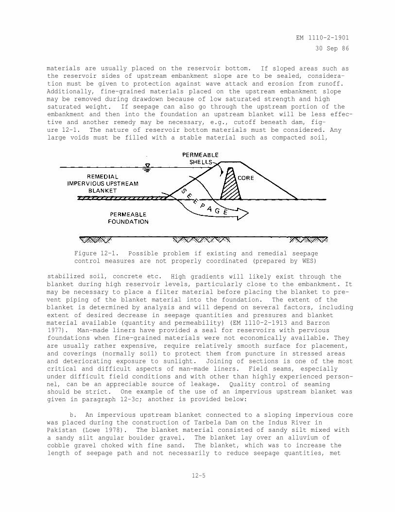
EM 1110-2-1901
30 Sep 86
materials are usually placed on the reservoir bottom. If sloped areas such asthe reservoir sides of upstream embankment slope are to be sealed, considera-tion must be given to protection against wave attack and erosion from runoff.Additionally, fine-grained materials placed on the upstream embankment slopemay be removed during drawdown because of low saturated strength and highsaturated weight. If seepage can also go through the upstream portion of theembankment and then into the foundation an upstream blanket will be less effec-tive and another remedy may be necessary, e.g., cutoff beneath dam, fig-ure 12-1. The nature of reservoir bottom materials must be considered. Anylarge voids must be filled with a stable material such as compacted soil,
Figure 12-1. Possible problem if existing and remedial seepagecontrol measures are not properly coordinated (prepared by WES)
stabilized soil, concrete etc. High gradients will likely exist through theblanket during high reservoir levels, particularly close to the embankment. Itmay be necessary to place a filter material before placing the blanket to pre-vent piping of the blanket material into the foundation. The extent of theblanket is determined by analysis and will depend on several factors, includingextent of desired decrease in seepage quantities and pressures and blanketmaterial available (quantity and permeability) (EM 1110-2-1913 and Barron1977). Man-made liners have provided a seal for reservoirs with perviousfoundations when fine-grained materials were not economically available. Theyare usually rather expensive, require relatively smooth surface for placement,and coverings (normally soil) to protect them from puncture in stressed areasand deteriorating exposure to sunlight. Joining of sections is one of the mostcritical and difficult aspects of man-made liners. Field seams, especiallyunder difficult field conditions and with other than highly experienced person-nel, can be an appreciable source of leakage. Quality control of seamingshould be strict. One example of the use of an impervious upstream blanket wasgiven in paragraph 12-3c; another is provided below:
b. An impervious upstream blanket connected to a sloping impervious corewas placed during the construction of Tarbela Dam on the Indus River inPakistan (Lowe 1978). The blanket material consisted of sandy silt mixed witha sandy silt angular boulder gravel. The blanket lay over an alluvium ofcobble gravel choked with fine sand. The blanket, which was to increase thelength of seepage path and not necessarily to reduce seepage quantities, met
12-5
EM 1110-2-1901
30 Sep 86
the piping criteria, D15 (alluvium) < 5D85 (blanket), Appendix D. As thereservoir emptied after first filling, several sinkholes and cracks were notedin the blanket. Sinkholes ranged from 1 to 15 ft in diameter and 4 to 6 ft indepth. It was felt that uneven settlement during the first reservoir fillingcaused tension and compression cracks in the blanket which allowed considerableseepage into the underlying sand-choked gravel. In areas where the sand wasless dense, the seepage moved the sand down to form a layer in the lower partof the gravel. This created open work gravel just beneath the blanket, andfines from the blanket moved into and through this open layer forming the sink-holes. Sinkholes were filled with filter material and mounded over withblanket material. Typically, the blanket mounds were approximately 15 ft highand extended 30 to 35 ft beyond the sinkhole edge. After filling of the reser-voir, sinkholes were located by side-scan sonar and filled with a mixture offilter material and silt from self-propelled bottom dump barges. Each sinkholegenerally received 50 barge loads of material. Sinkholes continued to be dis-covered and covered over another 3-4 years after the initial remedial action.Siltation on the reservoir blanket and filling of sinkholes have reducedseepage about one half.
12-6. Downstream Berm. Berms control seepage by increasing the weight of thetop stratum so that the weight of the berm plus top stratum is sufficient toresist uplift pressure. If of low permeability, they will reduce seepage, butincrease uplift pressures beneath the downstream toe of the dam since theyforce seepage to exit further downstream of the dam. If pervious, they mustbe designed as a filter or with an underlying filter to prevent upward migra-tion of line particles from the foundation materials beneath them. Again, aseepage analysis must be made to determine the resisting load required of theberm. Downstream slope stability of the embankment will normally increasebecause of the resistance to sliding provided by the berm. Huntington Districthas employed berms as remedial measures at several flood control dams in theMuskingum River flood control system (Coffman and Franks 1982). Similarity ofthe embankments and environments allowed a standard remedial action for severalof the dams at the downstream embankment toe. A 3- to 7-ft-thick perviousblanket of appropriate length is placed over the soft seepage areas at thedownstream toe. This adds weight and provides a working platform for instal-lation of relief wells at points of excessive seepage.. Another example of astability berm is given in the Addicks and Barker Dams example,paragraph 12-7a.
12-7. Slurry Trench Cutoff. Two major technical considerations in the use ofslurry trenches as remedial seepage control measures are (a) the effect onstability of the embankment due to excavation of the trench and the presenceof a vertical plane of relatively weak soil (in the case of a soil-bentonitebackfill) and (b) tying the slurry trench to other existing or proposed seep-age control measures. If a competent upstream blanket exists, the trench maybe placed upstream of the embankment and tied to the blanket or may be placedthrough the dam and any pervious substratum if stability requirements are met.A cement-bentonite backfill may be placed in panels or a concrete wall may beplaced in separately excavated elements if an open trench and the relativelyweak soil-bentonite backfill are unacceptable because of stability risks. Thefollowing experiences with slurry trenches provide general examples of thiscutoff type as a remedial measure.
12-6
EM 1110-2-1901
30 Sep 86
a. Addicks and Barker Dams, Houston, Tex. (U. S. Army Engineer District,Galveston 1977a; U. S. Army Engineer District, Galveston 1977b; U. S. ArmyEngineer District, Galveston 1983). Completed in the late 1940's, Addicks andBarker Dams are rolled earth embankments providing flood control in the Hous-ton, Texas, area, with respective maximum heights of 48.5 and 36.5 ft abovestreambed. Neither normally impound water except in periods of rainfall. Theembankments contain some silts and sands, foundations have silt and sandlayers, and upstream borrow areas expose the foundation permeable layers. Atthe time of construction, these conditions were not considered, significantbecause of the large discharge capability and short detention time of thereservoirs. Residential and commercial development of the downstream localarea caused several changes in operating conditions which increased detentiontime and made the effect of seepage more critical. These included restrictionof discharge rates and construction of drainage channels on non-Federal landwithin 200-300 ft downstream of the center line of the dams which expose thepervious portion of the foundation. Erosion of the drainage channel slopes onthe side of the channel nearest the dam and boils in the channel bottom duringtimes of low reservoir impoundment indicated the potential for dangerous seep-age conditions during high reservoir levels. Downstream piezometers alsoindicated a quick response to changes in reservoir levels. This exampledescribes remedial actions at Addicks Dam; actions at Barker Dam were similar.Several remedial measures were considered:
(1) Downstream drainage blanket and stability berm - rejected due torequirement for additional right-of-way and Government responsibility formaintenance of local interest's drainage ditch.
(2) Downstream drainage blanket, stability berm, and relief well systemand downstream slurry trench - (relief wells between embankment toe and slurrytrench) very positive control (blanket and berm control embankment seepagewhile wells and slurry trench control underseepage), but very costly, long-term well maintenance required, and all seepage forces would be directed atthe embankment toe.
(3) Same plan as (2) except slurry trench replaced with steel sheet pilecutoff - same reasoning as (2) except sheet pile would greatly increase cost.
(4) Slurry trench cutoff through embankment and foundation - a verypositive, controlled cutoff for embankment and foundation; no maintenance; allwork on Government property; less costly and quicker than other alternatives.For most of the remedial work, alternative (4) was chosen, though for selectedlengths of the embankment where they were the best alternative, alterna-tive (1) was used and some relief wells were placed. With a maximum depth of64 ft and width of 3-5 ft, the slurry trench penetrated 2-4 ft into a rela-tively impervious clay underlying the pervious foundation materials. Fig-ure 12-2 provides a general cross section of the design. The trench wasplaced 10-20 ft upstream of the embankment center line with equipment workingfrom a platform established by degrading the upper portion of the embankment.Cemented materials, present in some portions of the excavation, were broken bydropping a 10-ton percussion tool on the cemented layers. Portions of thetrench collapsed but were successfully reexcavated. Additionally, small (3-in.diameter) tunnels were encountered in the upstream side of the trench but were
12-7
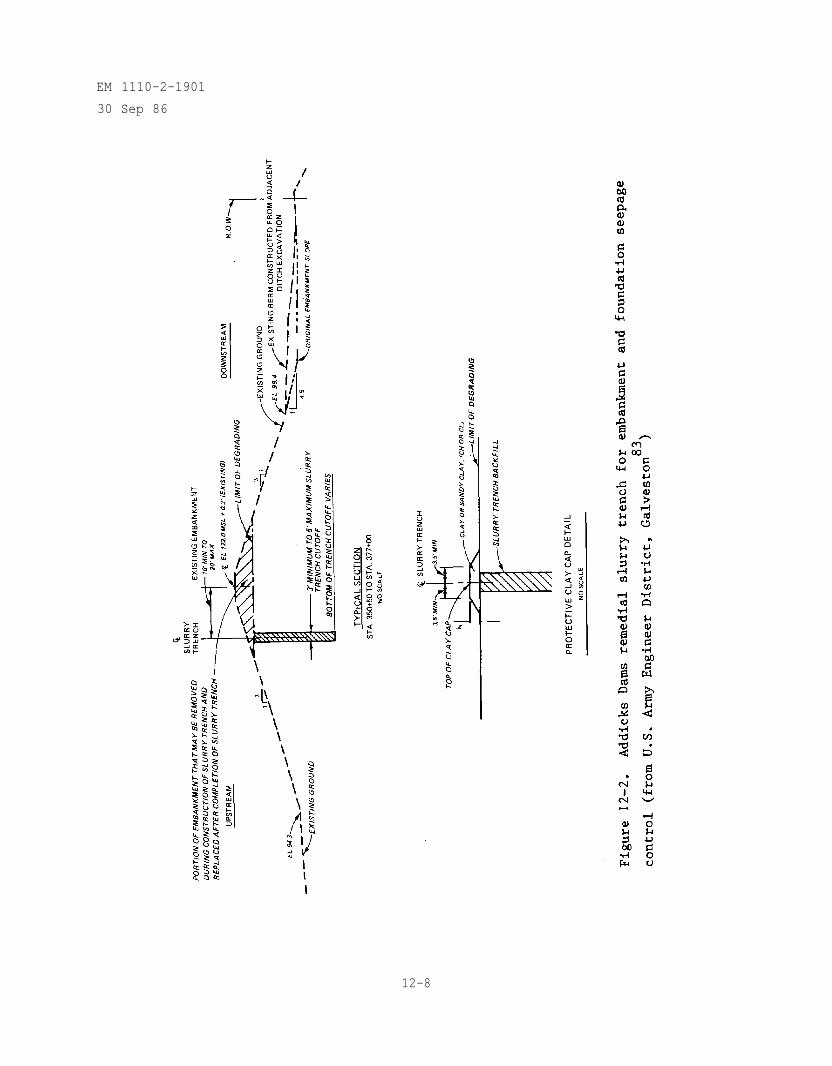
EM 1110-2-1901
30 Sep 86
12-8
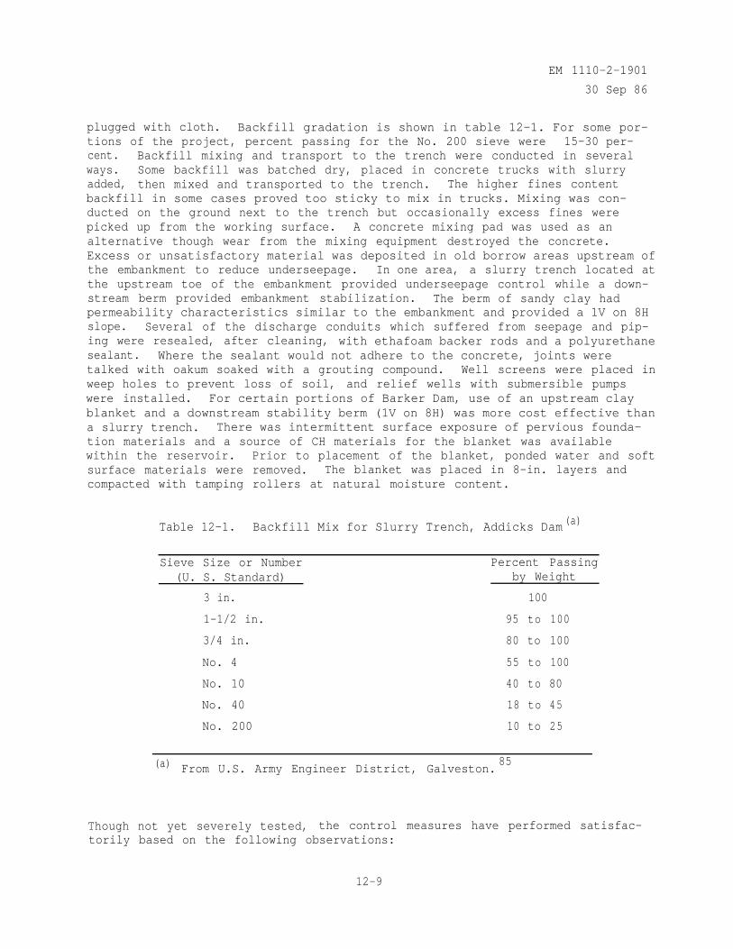
EM 1110-2-1901
30 Sep 86
plugged with cloth. Backfill gradation is shown in table 12-1. For some por-tions of the project, percent passing for the No. 200 sieve were 15-30 per-cent. Backfill mixing and transport to the trench were conducted in severalways. Some backfill was batched dry, placed in concrete trucks with slurryadded, then mixed and transported to the trench. The higher fines contentbackfill in some cases proved too sticky to mix in trucks. Mixing was con-ducted on the ground next to the trench but occasionally excess fines werepicked up from the working surface. A concrete mixing pad was used as analternative though wear from the mixing equipment destroyed the concrete.Excess or unsatisfactory material was deposited in old borrow areas upstream ofthe embankment to reduce underseepage. In one area, a slurry trench located atthe upstream toe of the embankment provided underseepage control while a down-stream berm provided embankment stabilization. The berm of sandy clay hadpermeability characteristics similar to the embankment and provided a 1V on 8Hslope. Several of the discharge conduits which suffered from seepage and pip-ing were resealed, after cleaning, with ethafoam backer rods and a polyurethanesealant. Where the sealant would not adhere to the concrete, joints weretalked with oakum soaked with a grouting compound. Well screens were placed inweep holes to prevent loss of soil, and relief wells with submersible pumpswere installed. For certain portions of Barker Dam, use of an upstream clayblanket and a downstream stability berm (1V on 8H) was more cost effective thana slurry trench. There was intermittent surface exposure of pervious founda-tion materials and a source of CH materials for the blanket was availablewithin the reservoir. Prior to placement of the blanket, ponded water and softsurface materials were removed. The blanket was placed in 8-in. layers andcompacted with tamping rollers at natural moisture content.
Table 12-1. Backfill Mix for Slurry Trench, Addicks Dam (a)
Sieve Size or Number(U. S. Standard)
3 in.
1-1/2 in.
3/4 in.
No. 4
No. 10
No. 40
No. 200
Percent Passingby Weight
100
95 to 100
80 to 100
55 to 100
40 to 80
18 to 45
10 to 25
(a) From U.S. Army Engineer District, Galveston.85
Though not yet severely tested, the control measures have performed satisfac-torily based on the following observations:
12-9
EM 1110-2-190130 Sep 86
(a) Foundation downstream piezometers do not respond to reservoir levelsexperienced so far.
(b) Phreatic surface has been raised upstream of the slurry trench.
(c) No embankment seepage, but there have been no significant pools.
(d) Settlement plates indicate no significant settlement of the slurrytrench. Though the restored embankment has cracked in the area of thetrenches, inadequate compaction of the embankment fill is considered thecause.
b. Wolf Creek Dam, Ky. (Fetzer 1979). Constructed in the 1940's, WolfCreek Dam is a 200-ft-high combination earthfill and concrete dam founded onlimestone containing shale and solution cavities. During excavation of a10-ft-wide cutoff trench, several interconnected solution cavities were dis-covered in the limestone. These were backfilled for a short distance withimpervious material, and a 50-ft-deep single-line grout curtain was placedbeneath the bottom of the cutoff trench. In 1967, muddy flow was observed inthe tailrace, a small sinkhole developed near the downstream toe, and wet areasexisted near the downstream toe. In 1968, a larger sinkhole developed (13 ftwide, 10 ft deep) and drilling revealed solution features running perpendicularand parallel to the dam axis. It was concluded that reservoir water waspassing beneath the cutoff trench. Grout lines were placed along the dam axisnear the embankment-concrete contact and downstream of this area. During1971-1972, an overall assessment of the seepage problem was made since theremedial grouting had only addressed about 200 ft of the 4,000-ft embankmentportion of the dam. A diaphragm concrete cutoff wall was considered the bestsolution because it could be installed without draining the reservoir, a verycostly operation due to reservoir use. Explorations , which included boringsspaced on 3.1-ft centers along the axis of the wall (parallel to the dam axis),defined the depth and length of the wall. Depth was 10 ft below the lowestindication of solution activity (maximum depth 278 ft) and length was 2,239 ft.In 1974, a request for technical proposals resulted in seven proposals with twoacceptable. In the second stage, a bid invitation was issued and an award wasmade for a wall in the area of the switchyard and 989 ft of the wall along thedam axis. The award in 1975 was followed by a second competition and an awardin 1977 for the remaining 1,250 ft of the axis wall. The wall consists ofalternate cylindrical primary elements and connecting secondary elementsinstalled using bentonite slurry, figure 9-14. Primary elements are2.17-ft-diam steel casings filled with tremied concrete (see table 9-8 for mixproportions). Weak cement grout fills the volume between excavation walls andthe casing. A 25-ft-deep core hole was drilled beyond the bottom of each pri-mary element to explore for cavities and was pressure-tested and grouted priorto the placement of a closed-end primary casing. The primary element wasrequired to set for a minimum of 20 days before excavation of the secondaryelement which is also filled with tremied concrete. Frequent piezometerreadings (as often as every 4 hours) were made during construction to determinethe hydraulic condition of the embankment and foundation and warn of anypotentially critical seepage conditions. Excavation and drilling were closelymonitored to observe any drill rod drops or mud losses. Sealers and reservemud, constantly on hand, provided for emergencies. Grout takes around
12-10
EM 1110-2-1901
30 Sep 86
the primary casings and volume of concrete used in the secondary elements wereclosely monitored as was the embankment in general. Efficient management of alarge number of observations was necessary to determine the current conditionof the dam. The lack of major losses of slurry, grout, or concrete duringconstruction was probably due to the densely spaced borings and grouting doneduring the earlier exploration program. Wall construction, completed in 1979,took approximately 4 years and two construction contracts. Subsequentpiezometric levels indicate the wall is a successful seepage barrier.
c. Camanche Dike 2, California (Anton and Dayton 1972). One of severalearthfill dikes containing Camanche Reservoir, Dike 2, is a zoned earth embank-ment about 70 ft high founded on alluvium containing an upper 20-ft strata ofclayey sand underlain by layered silty-to-fine uniform sand stratum. Theunderlying sand stratum varies in permeability with its lower portion contain-ing gravel. Original construction involved extending the core horizontally tothe upstream toe and discing and compacting the top of the alluvium to 1,000 ftupstream of the dike axis. This was expected to provide acceptable underseep-age conditions , while providing the option of tying an upstream cutoff throughthe alluvium to the core if operating underseepage conditions were intolerable.After reservoir filling, underseepage proved extensive and flowed over down-stream property. Lowering of the reservoir reduced the seepage and revealedholes in the compacted alluvium upstream of the embankment. Several seepagecontrol methods, including upstream impervious blanket, grout curtain, reliefwells, downstream drains, sheet piles, and others, were considered. Evaluationof the options resulted in choosing an upstream slurry trench. This methodprovided a positive cutoff, minimized piping potential, allowed retention of apartial reservoir, and was the least expensive of positive cutoff methods.Placed 50 ft upstream of the upstream berm toe, the 1,660-ft-long slurrytrench, 8 ft wide, extended through the alluvial materials to a maximum depthof 95 ft. Backfill specifications required a 4-in. slump and a gradation asshown in Table 12-2. An 8- to 11-ft-deep sandy clay blanket protected by a1-ft-thick cobble and gravel cover connected the slurry trench to the horizon-tal core extension. Excess slurry was blended into the top portion of theblanket to decrease blanket permeability. Since slurry trench placement,downstream piezometers reflect decreased influence of reservoir levels withonly very small seepage flows at high, prolonged reservoir levels. Two poten-tial sources of seepage are the somewhat pervious bedrock formation which theslurry trench is keyed into and the sandy clay blanket connection between theslurry trench and extended core. Connection of the 8- to 11-ft-deep blanket tothe slurry trench after placement of the slurry was difficult and may allowreservoir leakage into the alluvium. Placement of the blanket or a partialthickness prior to slurry trench construction was recommended. This wouldprovide a platform for construction of the slurry trench and allow a moresecure attachment of the trench to the blanket. This procedure has beenstandard practice on many subsequent slurry trench projects.
12-8. Relief Wells. Though Chapter 9 describes design and installation ofrelief wells, additional factors must be considered when relief wells are usedfor remedial seepage control. Relief wells can relieve excessive uplift andpotential piping when pervious layers are overlain by relatively imperviousstrata by providing controlled release of relatively large volumes of water.Relief wells, as compared with cutoffs, allow loss of reservoir water and
12-11
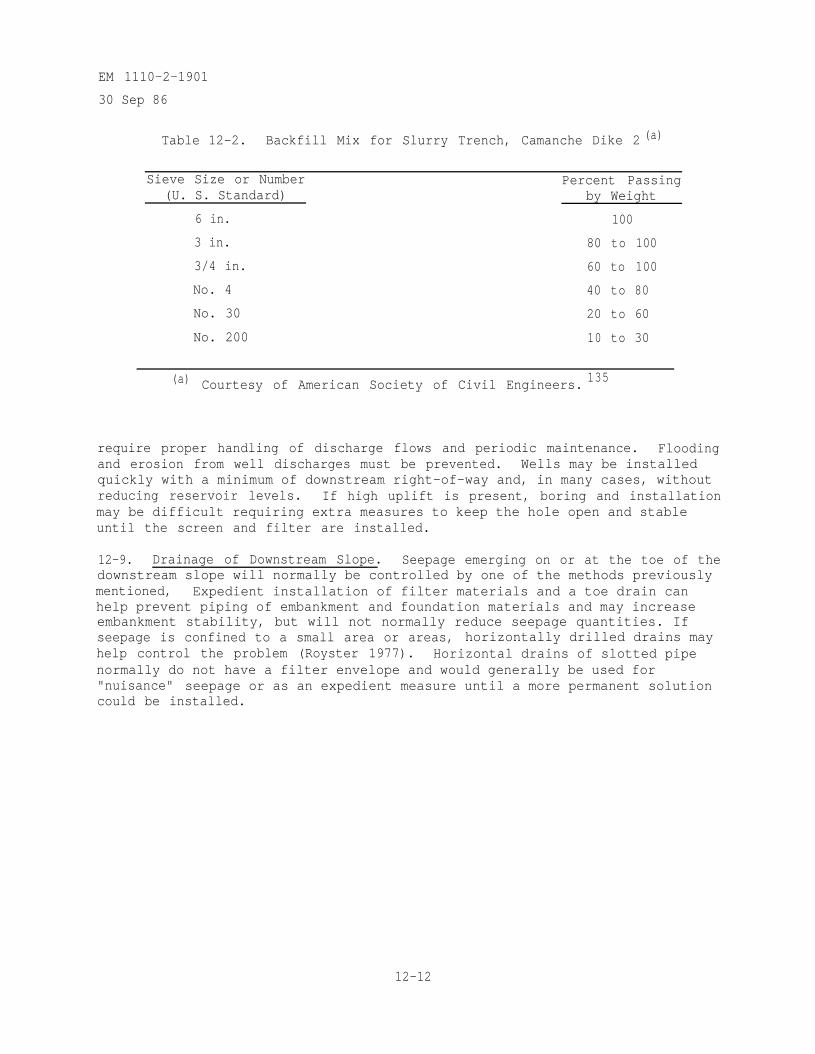
EM 1110-2-1901
30 Sep 86
Table 12-2. Backfill Mix for Slurry Trench, Camanche Dike 2 (a)
Sieve Size or Number(U. S. Standard)
6 in.
3 in.
3/4 in.
No. 4
No. 30
No. 200
Percent Passingby Weight
100
80 to 100
60 to 100
40 to 80
20 to 60
10 to 30
(a) Courtesy of American Society of Civil Engineers. 135
require proper handling of discharge flows and periodic maintenance. Floodingand erosion from well discharges must be prevented. Wells may be installedquickly with a minimum of downstream right-of-way and, in many cases, withoutreducing reservoir levels. If high uplift is present, boring and installationmay be difficult requiring extra measures to keep the hole open and stableuntil the screen and filter are installed.
12-9. Drainage of Downstream Slope. Seepage emerging on or at the toe of thedownstream slope will normally be controlled by one of the methods previouslymentioned, Expedient installation of filter materials and a toe drain canhelp prevent piping of embankment and foundation materials and may increaseembankment stability, but will not normally reduce seepage quantities. Ifseepage is confined to a small area or areas, horizontally drilled drains mayhelp control the problem (Royster 1977). Horizontal drains of slotted pipenormally do not have a filter envelope and would generally be used for"nuisance" seepage or as an expedient measure until a more permanent solutioncould be installed.
12-12

EM 1110-2-1901
30 Sep 86
CHAPTER 13MONITORING PERFORMANCE OF SEEPAGE CONTROL MEASURES
13-1. General Considerations.
a. Before seepage control measures are implemented, site characteriza-tion by thorough exploration and testing is needed to determine if the seepagecontrol measures will serve the intended purpose. Knowledge of the in situsite conditions along with the purpose of the seepage control measure and itsphysical dimensions will help determine' the overall number and the placementof monitoring devices. Several factors which can be monitored that can leadto a conclusion regarding the safety of a dam are: (1) progressive increasein the volume of seepage flow, (2) removal of solids by the seepage,(3) increased uplift pressures or locally depressed gradients, and (4) soft orwet areas on the downstream embankment.
b. Monitoring the performance of seepage control measures can lead to acollective conclusion drawn from several measurements. The most common andeasiest monitoring is to rely on visual observations along with careful sur-face inspections at predetermined intervals. Another type of monitoring whichshould be completed before construction is the installation of piezometers,observation wells, and drainage collection systems to determine a site depen-dent pattern of behavior. Finally, the actual structure should be monitoredby the installation of a site specific network of piezometers, observationwells, and drainage collection systems with flow measurements designed for theanticipated seepage problems. A regular review of the data collected willgenerally detect major changes between subsequent readings but equally asimportant are the long-range trends manifested by steady changes or intermit-tent surges.
c. If it is determined during the monitoring process that a possibleproblem exists, an expanded instrumentation program may be needed. This couldinclude more piezometers, relief wells, etc., and a more extensive analysis ofthe seepage water; i.e., both a physical and chemical analysis of the sedimentand water including temperature, salt content, and resistivity which could becompared with samples from the embankment and possible seepage sources.According to the complexity of the problem and/or the economics versus safetyinvolved a group of other studies could be added including, but not limited to:resistivity and spontaneous potential of the embankment and foundation, dyetracing, infrared (aerial or portable ground based), and seepage acousticemissions. In most cases, the scope of the monitoring program will be deter-mined by the economics involved.
13-2. Piezometers for Seepage Pressures.
a. Foundation. To determine the performance of seepage control measures,a pattern of behavior should be established prior to and during constructionwhere long-term trends can be related to design or seepage conditions. Piezom-eters should generally be installed in all compressible foundation soils, thenumber being dependent on the extent and thickness of the strata. If possible,foundation piezometers should be installed-in the sections selected for embank-ment piezometers and should extend beyond the upstream and downstream toes a
13-1
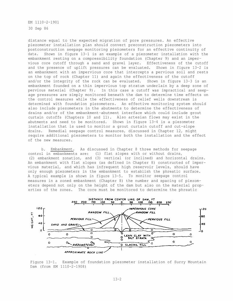
EM 1110-2-1901
30 Sep 86
distance equal to the expected migration of pore pressures. An effectivepiezometer installation plan should convert preconstruction piezometers intopostconstruction seepage monitoring piezometers for an effective continuity ofdata. Shown in figure 13-1 is an example of a piezometer installation with theembankment resting on a compressibility foundation (Chapter 9) and an imper-vious core cutoff through a sand and gravel layer. Effectiveness of the cutoffand the presence of uplift pressures can be evaluated. Shown in figure 13-2 isan embankment with an impervious core that intercepts a pervious soil and restson the top of rock (Chapter 11) and again the effectiveness of the cutoffand/or the integrity of the rock can be evaluated. Shown in figure 13-3 is anembankment founded on a thin impervious top stratum underlain by a deep zone ofpervious material (Chapter 9). In this case a cutoff was impractical and seep-age pressures are simply monitored beneath the dam to determine time effects onthe control measures while the effectiveness of relief wells downstream isdetermined with foundation piezometers. An effective monitoring system shouldalso include piezometers in the abutments to determine the effectiveness ofdrains and/or of the embankment-abutment interface which could include groutcurtain cutoffs (Chapters 10 and 11). Also artesian flows may exist in theabutments and need to be monitored. Shown in figure 13-4 is a piezometerinstallation that is used to monitor a grout curtain cutoff and cut-slopedrains. Remedial seepage control measures, discussed in Chapter 12, mightrequire additional piezometers to monitor both the installation and the effectof the new measures.
b. Embankment. As discussed in Chapter 8 three methods for seepagecontrol in embankments are: (1) flat slopes with or without drains,(2) embankment zonation, and (3) vertical (or inclined) and horizontal drains.An embankment with flat slopes (as defined in Chapter 8) constructed of imper-vious material, and which has infrequent high reservoir levels, should haveonly enough piezometers in the embankment to establish the phreatic surface.A typical example is shown in figure 13-5. To monitor seepage controlmeasures in a zoned embankment (Chapter 8) the number and spacing of piezom-eters depend not only on the height of the dam but also on the material prop-erties of the zones. The core must be monitored to determine the phreatic
Figure 13-1. Example of foundation piezometer installation of Surry MountainDam (from EM 1110-2-1908)
13-2
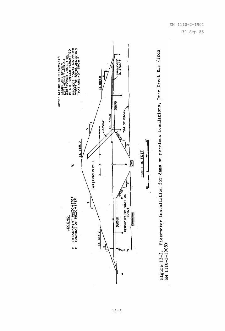
EM 1110-2-1901
30 Sep 86
13-3
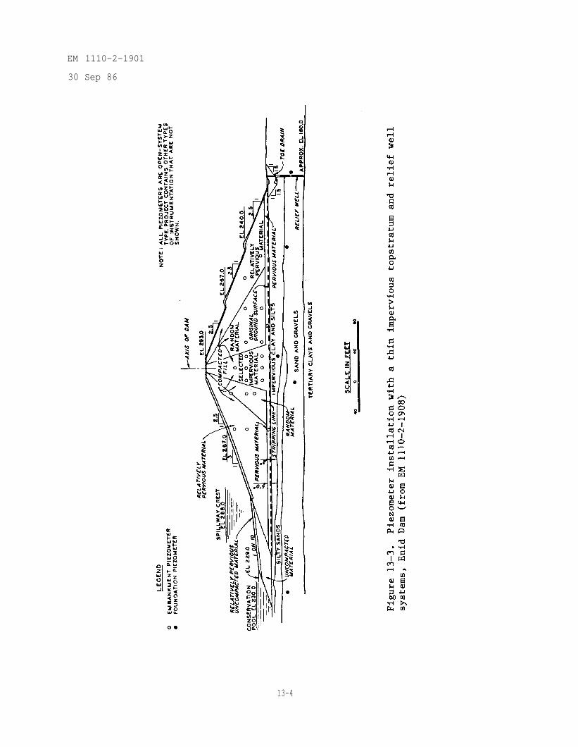
EM 1110-2-1901
30 Sep 86
13-4
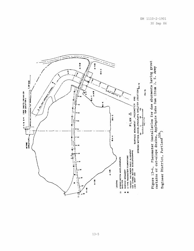
EM 1110-2-1901
30 Sep 86
13-5
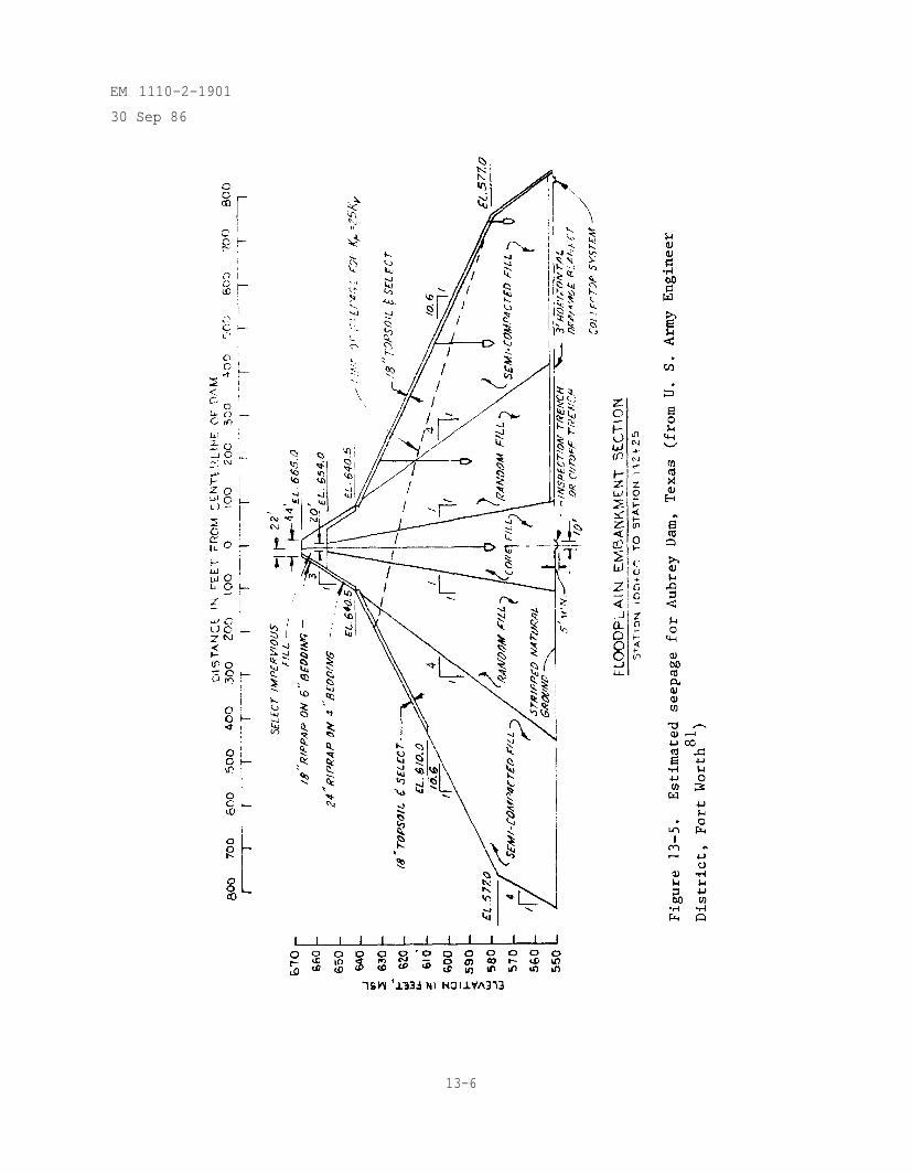
EM 1110-2-1901
30 Sep 86
13-6
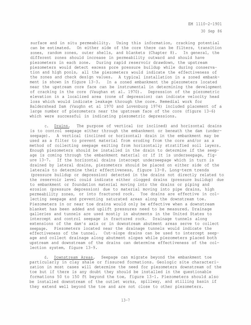
EM 1110-2-1901
30 Sep 86
surface and in situ permeability. Using this information, cracking potentialcan be estimated. On either side of the core there can be filters, transitionzones, random zones, outer shells, and blankets (Chapter 8). In general, thedifferent zones should increase in permeability outward and should havepiezometers in each zone. During rapid reservoir drawdown, the upstreampiezometers would detect excess pore pressure buildup while during conserva-tion and high pools, all the piezometers would indicate the effectiveness ofthe zones and check design values. A typical installation in a zoned embank-ment is shown in figure 13-3. In a zoned embankment the piezometers locatednear the upstream core face can be instrumental in determining the developmentof cracking in the core (Vaughan et al. 1970). Depression of the piezometricelevation in a localized area (cone of depression) can indicate velocity headloss which would indicate leakage through the core. Remedial work forBaldershead Dam (Vaughn et al 1970 and Lovenburg 1974) included placement of alarge number of piezometers near the upstream face of the core (figure 13-6)which were successful in indicating piezometric depressions.
c. Drains. The purpose of vertical (or inclined) and horizontal drainsis to control seepage either through the embankment or beneath the dam (under-seepage). A vertical (inclined or horizontal) drain in the embankment may beused as a filter to prevent material from eroding from the core and/or as amethod of collecting seepage exiting from horizontally stratified soil layers.Enough piezometers should be installed in the drain to determine if the seep-age is coming through the embankment material or if it is underseepage, fig-ure 13-7. If the horizontal drains intercept underseepage which in turn isdrained by lateral drains, piezometers should be placed on either side of thelaterals to determine their effectiveness, figure 13-8. Long-term trends(pressure buildup or depression) detected in the drains not directly related tothe reservoir level could indicate either clogged drains (pressure buildup) dueto embankment or foundation material moving into the drains or piping anderosion (pressure depression) due to material moving into pipe drains, highpermeability zones, or into fractured rock. Toe drains are effective in col-lecting seepage and preventing saturated areas along the downstream toe.Piezometers in or near toe drains would only be effective when a downstreamblanket has been added and uplift pressures need to be measured. Drainagegalleries and tunnels are used mostly in abutments in the United States tointercept and control seepage in fractured rock. Drainage tunnels alongextensions of the dam's axis or in downstream abutment areas serve to collectseepage. Piezometers located near the drainage tunnels would indicate theeffectiveness of the tunnel. Cut-slope drains can be used to intercept seep-age and collect drainage along abutment slopes while piezometers placed bothupstream and downstream of the drains can determine effectiveness of the col-lection system, figure 13-9.
d. Downstream Areas. Seepage can migrate beyond the embankment toeparticularly in clay shale or fissured formations. Geologic site characteri-zation in most cases will determine the need for piezometers downstream of thetoe but if there is any doubt they should be installed in the questionableformations 50 to 150 ft beyond the toe, figure 13-1. Piezometers should alsobe installed downstream of the outlet works, spillway, and stilling basin ifthey extend well beyond the toe and are not close to other piezometers.
13-7
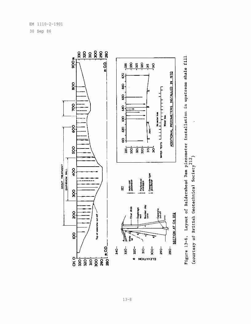
EM 1110-2-1901
30 Sep 86
13-8
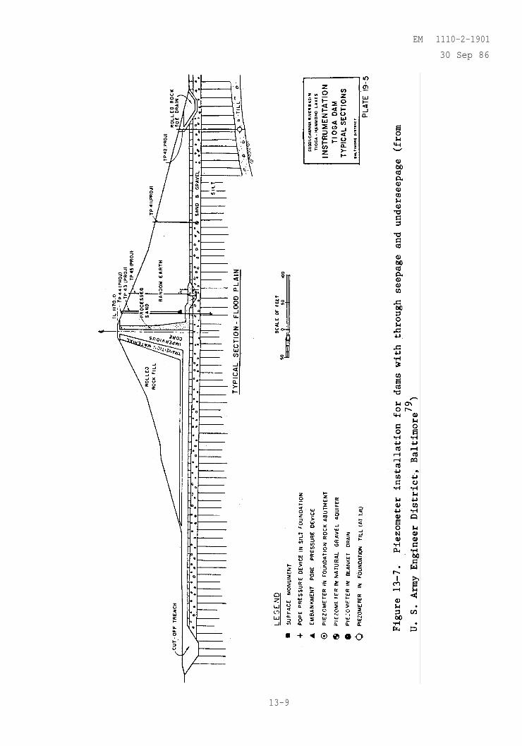
13-9
EM 1110-2-1901
30 Sep 86
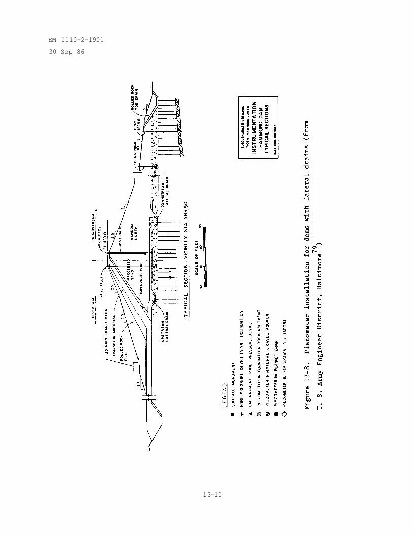
EM 1110-2-1901
30 Sep 86
13-10
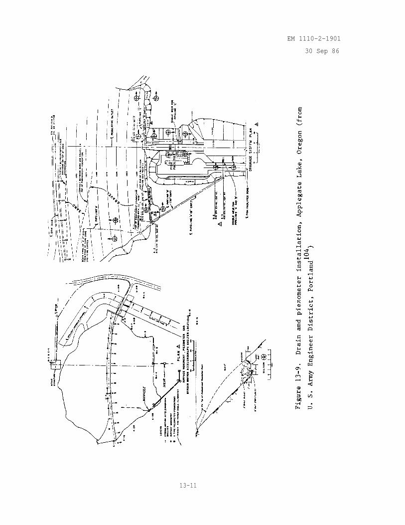
EM 1110-2-1901
30 Sep 86
13-11
EM 1110-2-1901
30 Sep 86
e. Near Relief Wells. If a relief well system has been installed, porepressures should be checked in the vicinity to evaluate the efficiency of thesystem. Piezometers should be located both upstream and downstream of therelief wells and should intercept the stratum being drained, figure 13-3. Ifthere is a line of wells, piezometers should also be installed generally atthe midpoint between the wells or at the point expected to have the highestpore pressures.
f. Spillways, Stilling Basins, and Outlet Works. Underseepage controlbeneath the stilling basins of spillways and outlet structures founded on per-vious foundations is generally provided by drainage blankets supplemented inthe case of stratified foundations by deep well systems (figures 13-10 and13-11). Drainage blankets extend beneath the chute slabs, if necessary. Asshown in figure 13-10, piexometers should be installed to check the effective-ness of the drainage blanket and relief wells, and to check pore pressurebeneath the outlet channel and against the stilling basin walls. Piezometersare used to check pore pressures occurring below the relief well system (fig-ure 13-10). Generally, a sheet pile wall, with a minimum penetration of15 ft, is installed along the downstream toe of the stilling basin to controlpiping and a piezometer installed downstream of the wall is needed to deter-mine the effectiveness of the wall.
13-3. Flow Measurements.
a. Weirs. Seepage flow measurement is an important parameter of damperformance. Most installations have used a relatively simple weir, measuringthe seepage over brass or stainless steel 90-deg V-notches like the collectionsystem shown in figures 13-12 and 13-13. A number of weirs can be installedin drainage galleries to determine flows from different sources, i.e., left orright abutment, dam underseepage, and total seepage. A certain amount ofsediments will settle out just upstream of the weir which is important if thesediment load is not continuous and occurs between visual inspections. If theseepage is exiting downstream of the dam and outside of a drainage collectionsystem, a weir pond can be formed in conjunction with the V-notch weir for thespecific purpose of determining long-term sediment content in the seepage.
b. Flumes. A flume is a short rigid-walled channel designed to con-strict the flow and so give rise to critical velocity. A single measurementof water level is sufficient to measure discharge at critical velocity. Themost commonly used flume for seepage measurements is the Parshall flume asshown in figure 13-14. Empirical charts for flow discharge have been devel-oped for specified flume dimensions (Bureau of Reclamation 1967). The flumecan be fabricated and placed in seepage flow that has been channelized. Thismethod is a relatively rapid and simple way to obtain precise flowmeasurements.
c. Relief Wells. Relief wells, as the name implies, are widely used torelieve pressures and control seepage through pervious strata beneath earthdams, spillways, and outlet works. A thorough knowledge of the geologic con-ditions and characteristics of the soils at the dam must be available todesign a system as part of initial construction or as remedial work. To beeffective, the well must flow but must not allow the loss of foundation
13-12
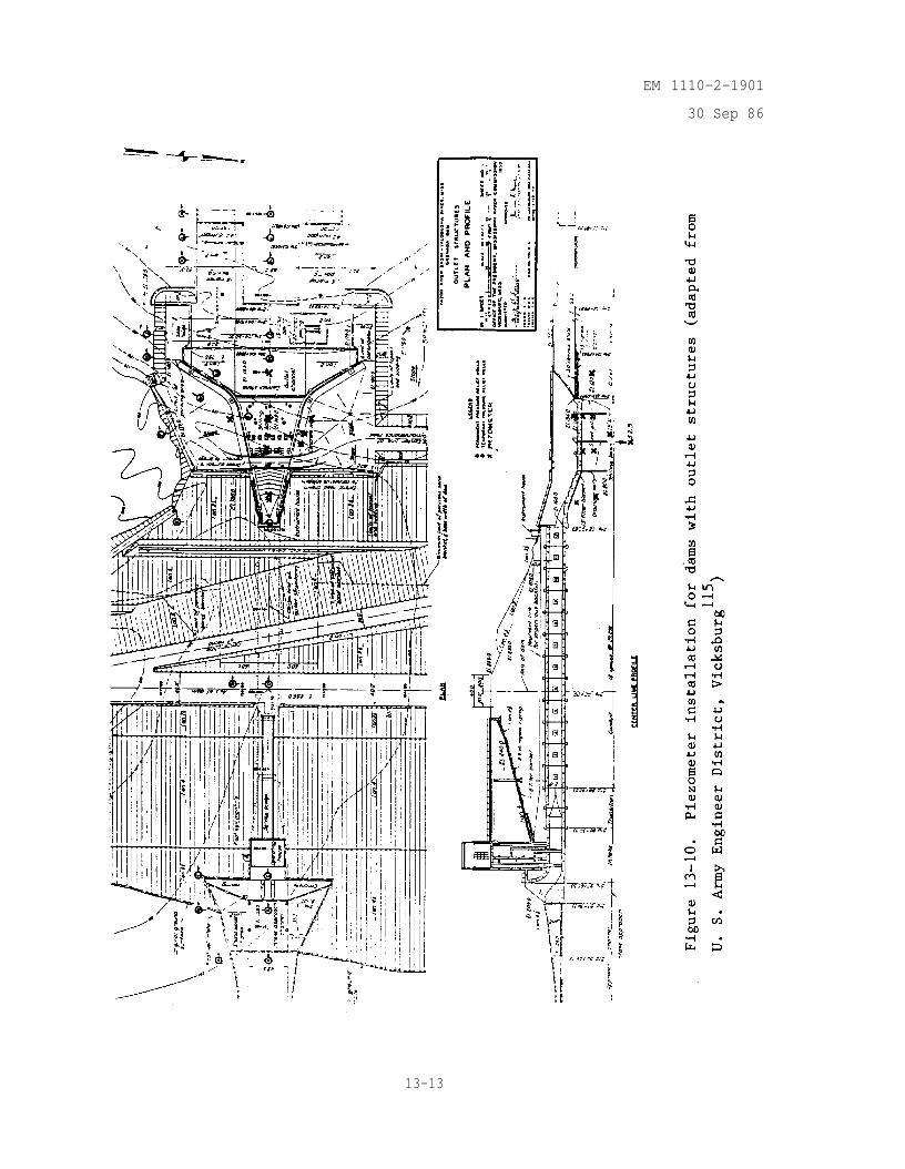
EM 1110-2-1901
30 Sep 86
13-13
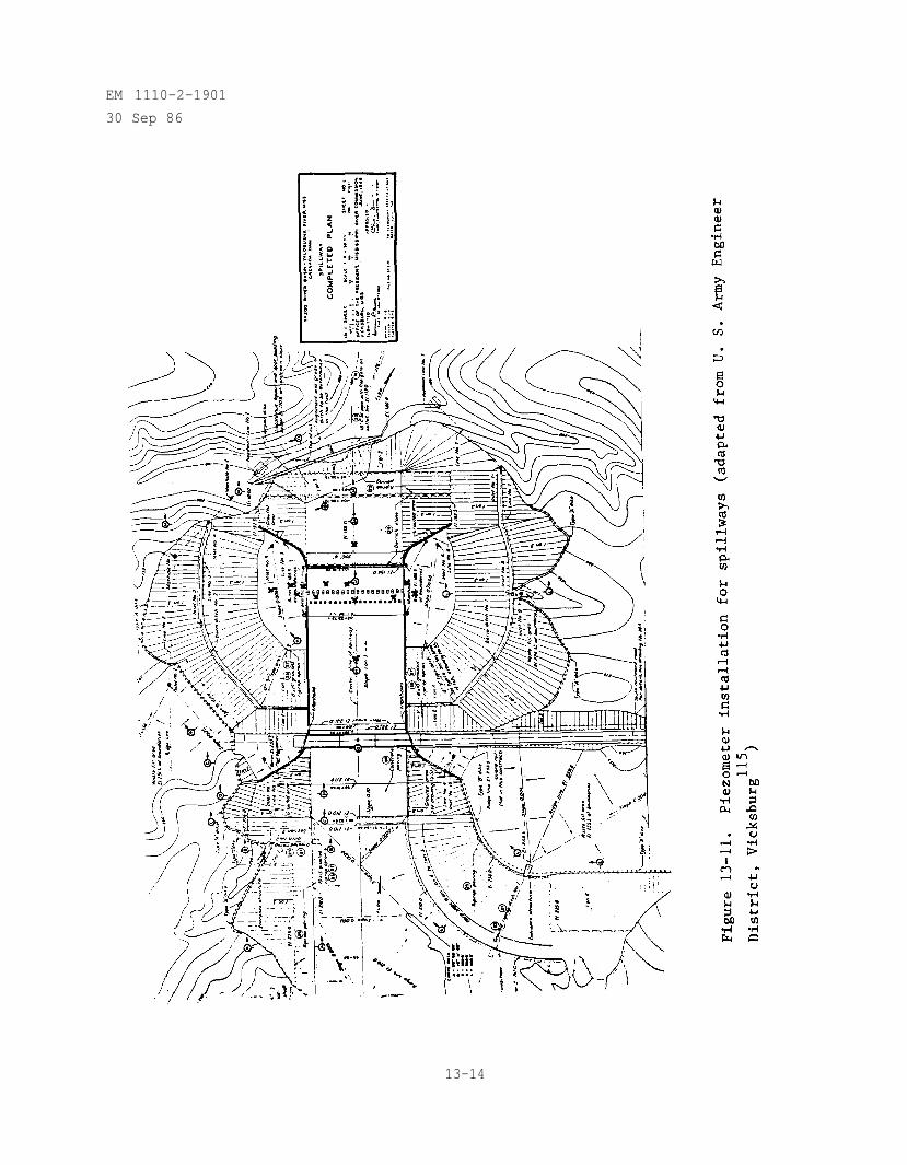
EM 1110-2-1901
30 Sep 86
13-14
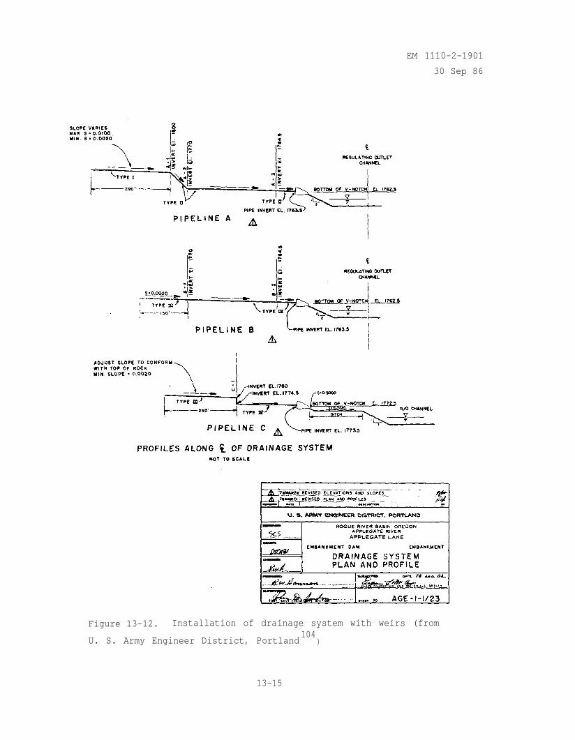
EM 1110-2-1901
30 Sep 86
Figure 13-12. Installation of drainage system with weirs (from
U. S. Army Engineer District, Portland104
)
13-15
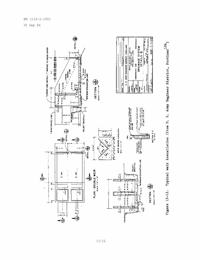
EM 1110-2-1901
30 Sep 86
13-16
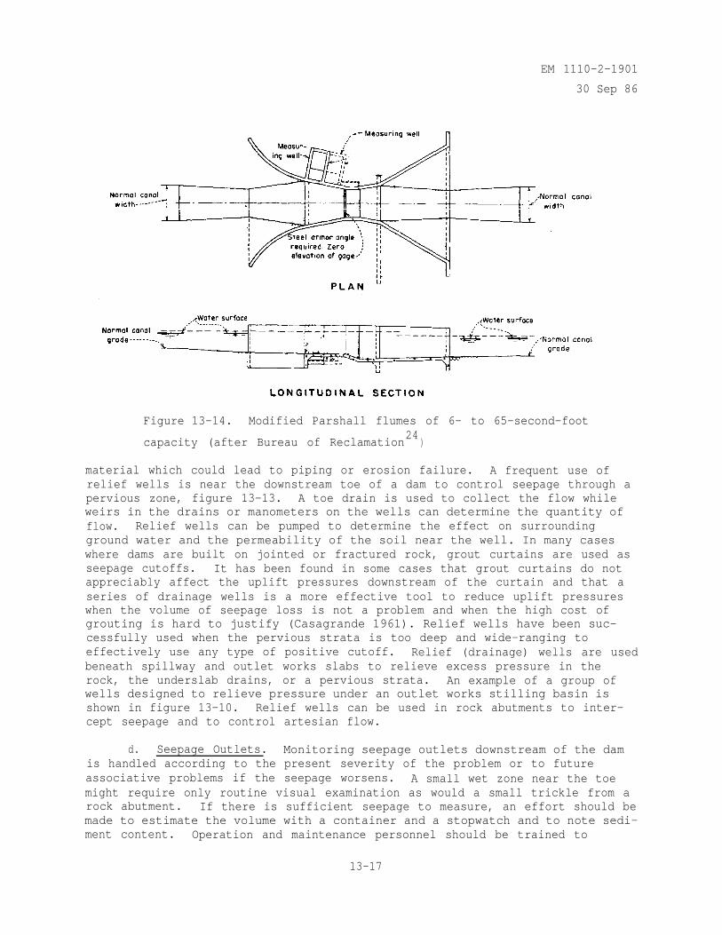
EM 1110-2-1901
30 Sep 86
Figure 13-14. Modified Parshall flumes of 6- to 65-second-foot
capacity (after Bureau of Reclamation24
)
material which could lead to piping or erosion failure. A frequent use ofrelief wells is near the downstream toe of a dam to control seepage through apervious zone, figure 13-13. A toe drain is used to collect the flow whileweirs in the drains or manometers on the wells can determine the quantity offlow. Relief wells can be pumped to determine the effect on surroundingground water and the permeability of the soil near the well. In many caseswhere dams are built on jointed or fractured rock, grout curtains are used asseepage cutoffs. It has been found in some cases that grout curtains do notappreciably affect the uplift pressures downstream of the curtain and that aseries of drainage wells is a more effective tool to reduce uplift pressureswhen the volume of seepage loss is not a problem and when the high cost ofgrouting is hard to justify (Casagrande 1961). Relief wells have been suc-cessfully used when the pervious strata is too deep and wide-ranging toeffectively use any type of positive cutoff. Relief (drainage) wells are usedbeneath spillway and outlet works slabs to relieve excess pressure in therock, the underslab drains, or a pervious strata. An example of a group ofwells designed to relieve pressure under an outlet works stilling basin isshown in figure 13-10. Relief wells can be used in rock abutments to inter-cept seepage and to control artesian flow.
d. Seepage Outlets. Monitoring seepage outlets downstream of the damis handled according to the present severity of the problem or to futureassociative problems if the seepage worsens. A small wet zone near the toemight require only routine visual examination as would a small trickle from arock abutment. If there is sufficient seepage to measure, an effort should bemade to estimate the volume with a container and a stopwatch and to note sedi-ment content. Operation and maintenance personnel should be trained to
13-17
EM 1110-2-1901
30 Sep 86
observe the situation especially during high reservoir levels. All seepageoutlets should be monitored to determine long-term trends. Sand boils devel-oping downstream require immediate attention. An estimate of the pore pres-sure involved can be determined by sandbagging around the boil to measure theheight of water rise. If the seepage exiting at the toe or abutment is severeand will require remedial work but the dam is not in imminent danger of fail-ing, collection systems must be designed as a pattern develops. Temporarycontrol measures such as toe drains and surcharge berms might be installedwith weirs to establish the severity and the trends of the seepage for use indesign of remedial work. Any changes noted during monitoring, i.e., volumechange, sediment load change, etc., should be considered important. After theremedial work has been designed it may include any number of the monitoringsystems discussed previously in this chapter. If the seepage is exiting from adrain system that is not being monitored internally, visual monitoring shouldcontinue at specified intervals and during heavy runoffs and high reservoirlevels.
13-4. Seepage Water Analysis.
a. Physical Analysis. Physical analysis of the seepage could includeinformation on suspended solids, temperature contours, and water resistivityvalues. This information may be obtained from physical testing of samples orby remote testing techniques.
(1) The amount of suspended solids in the seepage is an indication ofmaterial movement and piping. Although there are obvious problems with muddyor turbid flow, seepage which appears clear may often carry small amounts ofsuspended solids that would be detected by occasional samples and analysis.Sediment traps built in conjunction with manholes and weirs can be used toindicate the amount of suspended sediment and to obtain samples for chemicalanalysis.
(2) Several different methods of measuring temperature are designed tohelp locate seepage areas not yet visible and to trace seepage from its originto its exit. One remote sensing method (U.S. Army Engineer District, LosAngeles 1981) is an aerial survey which includes any or all of the following:(a) color photography, (b) color infrared photography, (c) thermal infrared,and (d) color oblique imagery. The basis for the study is that differentmaterials (wet or saturated versus dry) possess different heat absorptionrates; therefore, heat radiation rates will differ. Since the specific heatof water is higher than soil or rock, a warm zone in a known seepage area is asuspected seepage outlet. This method is intended for large areas but smallerareas can be covered by thermal infrared using portable hand-held units (Leach1982). A second method of thermal monitoring (U. S. Army District, LOSAngeles 1981) is to physically place an array of gages in and adjacent to theembankment and measure the diurnal temperature (temperature below the reach ofthe surface but within the annual temperature zone). A temperature fluctua-tion is interpreted as seepage related and becomes the basis for further studyin that zone. A vertical thermal contour can be made in present open systempiezometers or in remedial planned piezometers, again with temperature fluctu-ations or inversions interpreted as seepage related (U. S. Army Engineer Dis-trict, Los Angeles 1981 and Leach 1982). These data are interpreted or
13-18
EM 1110-2-1901
30 Sep 86
expanded by determining the temperature stratification of the reservoir, thetemperature of all known seepage sources, and the temperature at the seepageexits.
(3) Seepage can be monitored by the physical detection of tracer ele-ments such as dye and isotopes that have been introduced upstream of the seep-age exit either in the reservoir or a piezometer close to the suspected seep-age path. The dye selected should have a favorable absorption and decay rateand should meet state water quality control requirements. Samples taken frompiezometers, drains, and downstream exit points are monitored using an instru-ment capable of measuring parts per billion, e.g., a fluorometer for fluores-cein dye. By recording time of arrival and concentrations, interpretationscan be made as to the source of the seepage and the permeability of the strataalong the path of seepage. Environmental isotopes are also traced by obtain-ing samples which can be measured by a mass spectrometer for oxygen -18 anddeuterium and by the low level counting system for tritium.
(4) Another physical property of the seepage that can be measured isits conductance or resistance. Resistance which would be defined in the fieldby a resistivity survey is a measure of the ability to resist current flowthrough the seepage, a factor that is altered by the introduction of salt com-pounds, graphite, etc. A thorough sampling program from all possible sourcesof seepage, all seepage exits, and all available piezometers can produce agroup of resistivity values that is an important tool in defining seepagesources and possible paths. Using the geologic profile for the site, and bycomparing individual resistivity values or by comparison against a range ofknown values (Telford et al. 1976), an interpretation as to the source of theseepage and the strata through which it travels can be made.
b. Chemical Analysis. To monitor and interpret the chemical composi-tion of seepage requires a thorough knowledge of the surrounding geology orchemical analysis of samples in the different strata. If possible, a pre-construction chemical analysis should be conducted on all water sources and onany formation that might contribute minerals or salts or that might affectacidity or alkalinity.
(1) One important chemical property would be the salt concentrations inthe seepage. In this case to determine correlations, reservoir and ground-water concentrations are essential along with the mineral content of the area,e.g., water flowing through limestone would generally increase in chlorideconcentration. Minerals such as feldpoid sodalite and apatite (TurkishNational Committee 1976) or caliche in volcanic regions (U. S. Army EngineerDistrict, Los Angeles 1981) can release chloride ions into the water. Inter-pretation of chloride concentrations and its long-term trends can help deter-mine the relative length of seepage paths (shallow or deep seated), the extentof the leaching of the formation (whether concentrations are constant,increasing, or decreasing), and the source of the seepage (comparable concen-trations). Interpretation is sight-dependent and any of the above or possiblyother conclusions may be reached.
(2) Another chemical property needed for interpretation is the mineralcontent of the seepage. Mineral concentrations of calcium and magnesium
13-19
EM 1110-2-1901
30 Sep 86
bicarbonate containing dissolved carbon monoxide increase with length of flowthrough a limestone formation while flow through some clay minerals mayincrease concentrations of calcium and magnesium. Again, interpretation issite dependent and requires a thorough knowledge of the existing conditions.
(3) Stiff diagrams, as shown in figure 13-15, are a graphical method ofpresenting the anions and cations that are dissolved in the water (Hem 1970).The Stiff method uses ions plotted in the same sequence to give an irregularpolygonal shape or pattern. In tracing the movement of seepage water, theStiff patterns are plotted on a map of the site for various locations down-stream of the dam and the reservoir. The Stiff patterns may yield informationregarding the path(s) of seepage from the reservoir, prior land uses down-stream of the dam (feedlot, septic field, etc.), and type of formation(gypsum, dolomite, etc.).
13-5. Remote Sensing Methods.
a. Resistivity and Spontaneous Potential. As part of a total seepagestudy, resistivity and spontaneous potential methods have been used success-fully for seepage delineation in soil and rock (Cooper and Bieganousky 1978;Cooper, Koester, and Tranklin 1982; and Koester et al. 1984). Resistivitysurveys used as part of a seepage study help identify possible zones of highmoisture as a function of depth and location. After the surveys are correlatedto previous borings or geologic information, new borings are placed in theseepage flows. Spontaneous potential surveys are used to detect negative D. C.voltage anomalies in the surface electrical field which have been found toindicate zones of seepage flow (Cooper, Koester, and Tranklin 1982; andKoester et al. 1984). Although flow is indicated, depth to flow can not bedetermined for a given anomaly.
b. Photography. Methods using color, color infrared, aerial and groundbase thermal infrared, and color oblique photography were discussed previouslyin paragraph 13-4.a.
c. Refraction Seismic Surveys. Seismic surveys can be used indirectlyin a seepage study by providing a bedrock profile that can be used as an aidin determining the location and depths of observation wells, piezometers, andrelief wells. It is a quick and inexpensive method for obtaining subsurfaceprofiles.
d. Seepage Acoustic Vibrations. Acoustic emissions are the noisesgenerated whenever a material deforms or possibly by seepage whenever there isturbulent flow against and around a casing (Koerner, Lord, and McCabe 1977).The technique has been used to detect seepage by placing an accelerometer on awaveguide that extends to the bottom of a borehole and recording the vibrationspresent (Koerner, Lord, and McCabe 1977; and Leach 1982). Increases in emis-sions activity are interpreted as seepage flow. A similar technique thatconsists of lowering an acoustic microphone down into a reservoir has beenused to detect leakage on the upstream asphalt-covered face and in the reser-voir itself (Coxon and Crook 1976). One disadvantage would be high backgroundnoise levels.
13-20
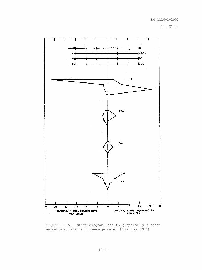
EM 1110-2-1901
30 Sep 86
Figure 13-15. Stiff diagram used to graphically presentanions and cations in seepage water (from Hem 1970)
13-21
EM 1110-2-1901
30 Sep 86
CHAPTER 14INSPECTION, MAINTENANCE, AND REHABILITATION OF
SEEPAGE CONTROL MEASURES
14-1. Introduction. Proper functioning of seepage control features requiresadequate maintenance, inspection, and, if necessary, rehabilitation. Someseepage control methods such as relief wells are in the best condition theywill ever be the day they are installed and developed, while others such assoil-bentonite slurry trench cutoffs may increase in effectiveness with time.All seepage control features must function effectively for the life of the damor be rehabilitated or, if necessary, replaced. The effectiveness of someseepage control methods, such as the toe trench drain, may be directlyobserved. For other seepage control methods, such as cutoffs, performancemonitoring (see Chapter 13) is essentially the only means of determining thedegree of effectiveness.
14-2. Inspection. The procedure for periodic inspection and continuing evalu-ation of dams is given in ER 1110-2-100. Procedures for reporting evidence ofdistress in dams are given in ER 1110-2-101. Procedures in these two ER's areoften supplemented by Division Regulations as well. Details concerning themonitoring performance of seepage control measures are given in Chapter 13.The first general field inspection for new earth and rock-fill dams is carriedout immediately after topping out the embankment. The initial inspection ofconcrete dams is accomplished prior to impoundment of reservoir water. Thesecond inspection for earth and rock-fill and concrete dams is made at areasonable stage of normal operating pool but no later than one year afterinitial impoundment has begun. Subsequent inspections will be made at one-yearintervals for the next four years, at two-year intervals for the followingfour years, and then may be extended to every five years if warranted. Theperiodic inspections provide the opportunity for a group of specialists tocritically examine a project for existing and/or potential problems, to recom-mend remedial action or changes in instrumentation , and to direct the attentionof the operating personnel toward the significant and critical features of aproject. However, the occasional inspection cannot take the place of dailyobservations required to detect potentially dangerous problems at an early andrepairable stage. Table 14-1 outlines the inspection, instrumentation, mainte-nance, and rehabilitation of seepage control facilities. Some seepage controlmethods such as embankment zonation, cutoffs, and upstream impervious blanketsare not amenable to visual inspection. Other methods such as flat slopesdownstream of the dam and downstream seepage berms are most accessible andshould be inspected daily during periods of full reservoir pool to ascertainthat they are functioning properly in controlling seepage. Other seepage con-trol facilities should be inspected on a regular schedule as shown intable 14-1.
14-3. Maintenance. Timely performance of maintenance on seepage controlfacilities is required for the facilities to perform satisfactorily. Someseepage control methods such as flat slopes downstream of the dam and down-stream seepage berms are accessible and require maintenance. Other seepagecontrol methods such as embankment zonation, cutoffs, and upstream imperviousblankets do not require maintenance. However, maintenance is required on theinstrumentation used to evaluate the degree of effectiveness of all seepage
14-1
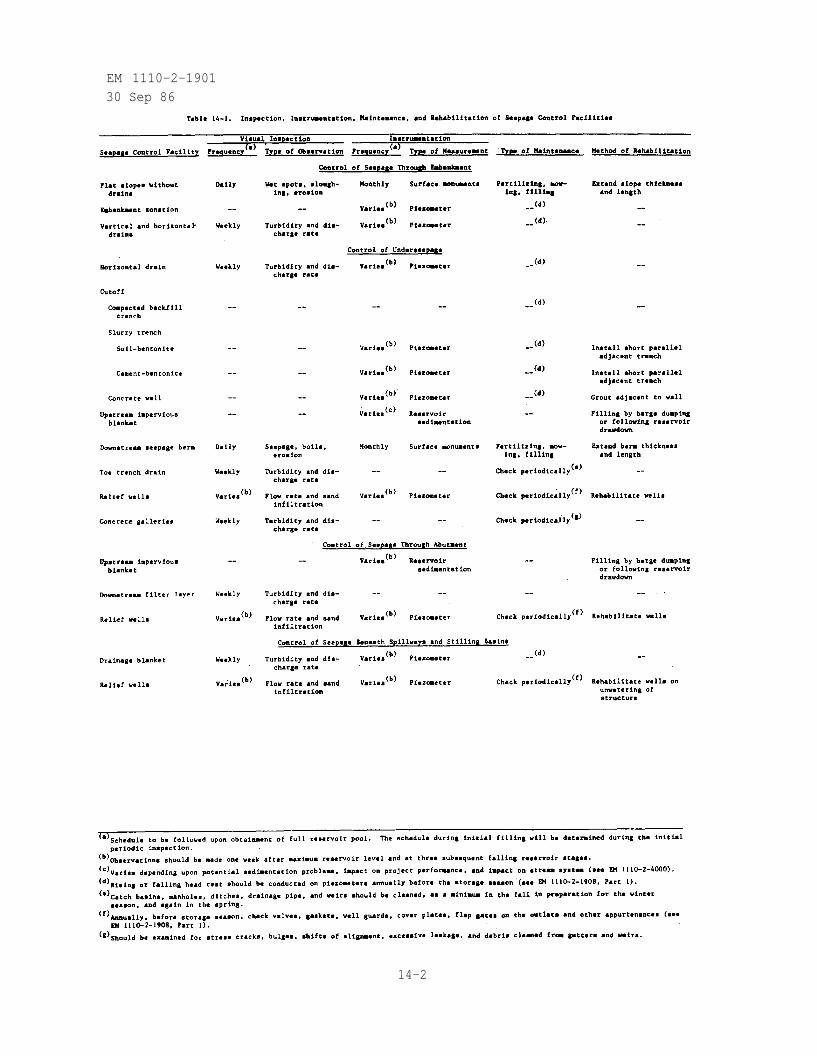
EM 1110-2-190130 Sep 86
14-2
EM 1110-2-1901
30 Sep 86
control methods. The type of maintenance to be conducted on seepage controlfacilities is given in table 14-1.
14-4. Rehabilitation. Inspection and maintenance of seepage control facili-ties may indicate the need for rehabilitation. The type of rehabilitation tobe conducted on various seepage control facilities is shown in table 14-1. Ifthe seepage control facility cannot be satisfactorily rehabilitated, remedialseepage control facilities should be installed (see Chapter 12). The majorityof rehabilitation of seepage control facilities is in connection with reliefwells. Often a relief well does not flow except during high reservoir levels.The water in the well becomes stagnant, various chemicals precipitate, algaegrows, and the efficiency of the well deteriorates. This will be manifestedby a fall in relief well discharge accompanied by a rise in piezometriclevels. Rehabilitation of a relief well is in essence a redevelopment of thewell. In addition to mechanical methods such as water jetting, surging, com-pressed air, and pumping, certain chemicals, detergents, and water softenerscan be used in the rehabilitation process.. Chemical tests on water samplesfrom the wells will indicate if and what chemicals are applicable. An exami-nation of the well screen with a borehole TV camera is recommended, turbidityof the water permitting, to determine the degree of deterloration and/orclogging of the screen. For well screens constructed of metal (no woodenscreens) that will not be damaged by acid, incrustation from calcium carbonatethat has cemented gravel filter particles can be removed by treatment withhydrochloric acid. For well screens constructed of metal, treatment withchlorine can remove bacterial growths of slimes. Iron oxides may be removedby treatment with polyphosphate and surging the well. Calcium hypochloritecan be used with polyphosphates to kill iron bacteria (Johnson Division,Universal Oil Products Co. 1972).
14-3
EM 1110-2-1901
30 Sep 86
APPENDIX AREFERENCES
Government Publications
1.
2.
3.
4.
5.
6.
7.
8.
9.
10.
11.
12.
13.
14.
15.
16.
17.
18.
19.
20.
TM 5-818-5.
TM 5-545.
ER 1110-2-100.
ER 1110-2-101.
EM 1110-2-1901.
EM 1110-2-1902.
EM 1110-2-1905.
EM 1110-2-1906.
EM 1110-2-1908.
EM 1110-2-1911.
EM 1110-2-1913.
EM 1110-2-2300.
EM 1110-2-2400.
EM 1110-2-2501.
EM 1110-2-3501.
EM 1110-2-3506.
EM 1110-2-4000.
Albritton, J., Jackson, L., and Bangert, R., "Foundation Grouting Prac-tices at Corps of Engineers Dams," TR GL-84-13, 1984, U. S. Army EngineerWaterways Experiment Station, P. O. Box 631, Vicksburg, MS 39180-0631.
Al-Hussaini, M., and Townsend, F. C., "Investigation of Tensile Strengthof Compacted Soils," Miscellaneous Paper S-74-10, Jun 1974, U. S. ArmyEngineer Waterways Experiment Station, P. O. Box 631, Vicksburg, MS39180-0631.
Banks, D. C., "Three-Dimensional Electrical Analogy Seepage ModelStudies; Appendix A: Flow to Circular Well Arrays Centered Inside a Cir-cular Source, Series G," Technical Report No. 3-619, Mar 1963, U. S. Army
A-1
EM 1110-2-1901
30 Sep 86
21.
22.
23.
24.
25.
26.
27.
28.
29.
30.
31.
Engineer Waterways Experiment Station, P. O. Box 631, Vicksburg, MS39180-0631.
Banks, D. C. "Three-Dimensional Electrical Analogy Seepage Model Studies;Appendix B: Flow to a Single Well Centered Inside a Circular Source,Series H," Technical Report No. 3-619, Mar 1965, U. S. Army EngineerWaterways Experiment Station, P. O. Box 631, Vicksburg, MS 39180-0631.
Bedinger, M. S., "Relationship Between Median Grain Size and Permeabilityin the Arkansas River Valley, Arkansas," Professional Paper 424-C, 1961,U. S. Department of the Interior, Geological Survey, 1717 H Street N.W.,Washington, DC 20277.
Bureau of Reclamation, Groundwater Manual, Denver, Colo., 1977. Avail-able from: Technical Information Center, U. S. Army Engineer/WaterwaysExperiment Station, P. O. Box 631, Vicksburg, MS 39180-0631.
Bureau of Reclamation, Water Measurement Manual, 2nd ed., 1967, U. S.Department of the Interior, P. O. Box 25007, Denver, CO 80225.
Cedergren, H. R., "Flow Net Studies for Several Dams," for U. S. ArmyEngineer District, Sacramento, Mar 1975, 650 Capitol Mall, Sacramento, CA95814.
Clay, F. M., A Century on the Mississippi, A History of the MemphisDistrict, U. S. Army Corps of Engineers 1876-1876, Jan 1976, U. S. ArmyEngineer District, Clifford Davis Federal Building, Memphis, TN 38103.
Clough, G. W., "An Evaluation of the Technical Feasibility of a SlurryTrench Cutoff for the Excavation for the Tensas-Cocodrie Pumping Plant,and a Review of Slurry Trench Specifications," 1978, report prepared forU. S. Army Engineer District, P. O. Box 60, Vicksburg, MS 39180.
Cobb, J. E., "Seepage Analysis Report - Stage 3, Specifications, CalamusDam, Nebraska," Technical Memorandum No. V-222-B-lg, Jan 1984, Bureau ofReclamation, P. O. Box 25007, Denver, CO 80225.
Cooley, R. L., Harsh, J. F., and Lewis, D. C., "Principles of Ground-Water Hydrology," Hydrologic Engineering Methods for Water ResourcesDevelopment, Vol 10, Apr 1972, U. S. Army Engineer Hydrologic EngineeringCenter, 609 Second Street, Davis, CA 95616.
Cooper, S. S., and Bieganousky, W. A., "Geophysical Survey of CavernousAreas, Patoka, Indiana," Miscellaneous Paper S-78-1, Jan 1978, U. S. ArmyEngineer Waterways Experiment Station, P. O. Box 631, Vicksburg, MS39180-0631.
Cooper, S. S., Koester, J. P., and Franklin, A. G., "Geophysical Investi-gation at Gathwright Dam," Miscellaneous Paper GL-82-2, Mar 1982, U. S.Army Engineer Waterways Experiment Station, P. O. Box 631, Vicksburg, MS39180-0631.
A-2

EM 1110-2-1901
30 Sep 86
32. Desai, C. S., "Seepage in Mississippi River Banks, Analysis of TransientSeepage Using a Viscous-Flow Model and Finite Difference and Finite Ele-ment Methods," Technical Report S-73-S, Report 1, May 1973, U. S. ArmyEngineer Waterways Experiment Station, P. O. Box 631, Vicksburg, MS39180-0631.
33. Desai, C. S., "Seepage in Mississippi River Banks; Analysis of TransientSeepage Using Viscous Flow Model and Numerical Methods," MiscellaneousPaper S-70-3, Report 1, Feb 1970, U. S. Army Engineer Waterways Experi-ment Station, P. O. Box 631, Vicksburg, MS 39180-0631.
34. Desai, C. S., and Kuppusamy, T., "Development of Phreatic Surfaces inEarth Embankments," report prepared for the Bureau of Reclamation, May1980, Department of Civil Engineering, Virginia Polytechnic Institute,Blacksburg, Va. Available from: Technical Information Center, U. S.Army Engineer Waterways Experiment Station, P. O. Box 631, Vicksburg, MS39180-0631.
35. Duncan, J. M., "Seepage Analysis for Columbia Lock and Dam," Miscellane-ous Paper No. 3-503, Jun 1962, U. S. Army Engineer Waterways ExperimentStation, P. O. Box 631, Vicksburg, MS 39180-0631.
36. Duncan, J. M., "Three-Dimensional Electrical Analogy Seepage ModelStudies," Technical Report No. 3-619, Mar 1963, U. S. Army EngineerWaterways Experiment Station, P. O. Box 631, Vicksburg, MS 39180-0631.
37. Edris, E. V., Jr., and Vanadit-Ellis, W., "Geotechnical Computer ProgramSurvey," Miscellaneous Paper GL-82-1, Mar 1982, U. S. Army EngineerWaterways Experiment Station, P. O. Box 631, Vicksburg, MS 39180-0631.
38. Environmental Protection Agency, "Manual of Methods for Chemical Analysisof Water and Wastes," EPA-625-6-76-003a, Jul 1976, 26 W. St. ClairStreet, Cincinnati, OH 45268.
39. Franke, P., "The Concrete-Pile Cutoff Wall According to the I.C.O.S. -Vedner Patent," Translation No. 54-6, Sep 1954, U. S. Army EngineerWaterways Experiment Station, P. O. Box 631, Vicksburg, MS 39180-0631.
40. Gerwick, B. C., Jr., Holland, T. C., and Komendant, G. J., "Tremie Con-crete for Bridge Piers and Other Massive Underwater Placements," ReportNo. FHWA-RD-81-153, Sep 1981, U.S. Department of Transportation, FederalHighway Administration, Washington, D. C. Available from: TechnicalInformation Center, U. S. Army Engineer Waterways Experiment Station,P. O. Box 631, Vicksburg, MS 39180-0631.
41. Guertin, J. D., and McTigue, W. H., "Groundwater Control Systems forUrban Tunneling," Groundwater Control in Tunneling, Vol 1, ReportNo. FHWA-RD-81-073, Apr 1982, U. S. Department of Transportation, FederalHighway Administration, Washington, D. C. Available from: TechnicalInformation Center, U. S. Army Engineer Waterways Experiment Station,P. O. Box 631, Vicksburg, MS 39180-0631.
A-3
EM 1110-2-1901
30 Sep 86
42.
43.
44.
45.
46.
47.
48.
49.
50.
51.
Hall, R. L., Tracy, F. T., and Radhakrishnan, N. "Documentation of Two-and Three-Dimensional Seepage Problems Using the Finite Element Method,"Miscellaneous Paper No. K-75-6, Jun 1975, U. S. Army Engineer WaterwaysExperiment Station, P. O. Box 631, Vicksburg, MS 39180-0631.
Hallford, C. R., "Fluid Trench Construction, Concrete Diaphragm Wall Con-struction," Lecture for Construction of Earth and Rockfill Dams Course,Mar 1983, U. S. Army Engineer Waterways Experiment Station, P. O.Box 631, Vicksburg, MS 39180-0631.
Hanson, J. E., "Impervious Cutoff by Means of Slurry Trench ConstructionMill Site Dam and Reservoir, Ferron Creek, Ferron Utah," 1972, U. S.Department of Agriculture, Soil Conservation Service, P. O. Box 11350,Salt Lake City, UT 84147.
Harza Engineering Company, "Engineering Investigations and Design Studiesfor Underseepage Control (Slurry Trench Cutoff) for Saylorville Dam, DesMoines River, Iowa," Nov 1965, report prepared for U. S. Army EngineerDistrict Clock Tower Building, Rock Island, IL 61201.
Hem, J. D., "Study and Interpretation of the Chemical Characteristics ofNatural Water," Water-Supply Paper No. 1473, 1970, U. S. Department ofInterior Geological Survey, 1717 H Street, Washington, DC 20277.
Holland, T. C., and Turner, J. R., "Construction of Tremie Concrete Cut-off Wall, Wolf Creek Dam, Kentucky," Miscellaneous Paper SL-80-10, Sep1980, U. S. Army Engineer Waterways Experiment Station, P. O. Box 631,Vicksburg, MS 39180-0631.
Jansen, R. B., Dams and Public Safety, 1980, U. S. Department of theInterior, Bureau of Reclamation, Denver Federal Center, Denver, CO80225.
Kealy, C. D., and Busch, R. A., "Determining Seepage Characteristics ofMill-Tailings Dams by the Finite Element Method," Report of Investiga-tions 7477, Jan 1971, U. S. Bureau of Mines, Spokane Mining ResearchCenter, Spokane, Wash. Available from: Technical Information Center,U. S. Army Engineer Waterways Experiment Station, P. O. Box 631,Vicksburg, MS 39180-0631.
Koester, J. P., et al, "Geophysical Investigations in Support of Clear-water Dam Comprehensive Seepage Analysis," Miscellaneous Paper GL-84-3,May 1984, U. S. Army Engineer Waterways Experiment Station, P. O.Box 631, Vicksburg, MS 39180-0631.
Leach, R. E., "Waterbury Dam Seepage Study," draft report prepared forU. S. Army Engineer District, New York, 1982, U. S. Army Engineer Water-ways Experiment Station, P. O. Box 631, Vicksburg, MS 39180-0631.
A-4
EM 1110-2-1901
30 Sep 86
52.
53.
54.
55.
56.
57.
58.
59.
60.
61.
62.
Lohman, S. W., et al., "Definition of Selected Ground-Water Terms -Revisions and Conceptual Refines," Water-Supply Paper 1988, 1972, U. S.Department of the Interior, Geological Survey, 1717 H Street, Washington,DC 20277.
Mansur, C. I., and Perret, W. R., "Efficacy of Partial Cutoffs for Con-trolling Underseepage Beneath Levees," Technical Memorandum No. 3-267,Jan 1949, U. S. Army Engineer Waterways Experiment Station, P. O.Box 631, Vicksburg, MS 39180-0631.
Mantei, C. L., and Cobb, J. E., "Seepage Analysis, Progress Report -Stage 2, Specifications, Calamus Dam, Nebraska," Technical MemorandumNo. V-222-B-1-F, 1981, Bureau of Reclamation, P. O. Box 25007, Denver, CO80225.
Mantei, C. L., Esmiol, E. E., and Cobb, J. E., "Seepage Analysis, CalamusDam - Stage I, Pick-Sloan Missouri River Basin Project, Nebraska,"Technical Memorandum No. V-224-A, Mar 1980, Bureau of Reclamation, P. O.Box 25007, Denver, CO 80225.
McAnear, C. L., and Trahan, C. C., "Three-Dimensional Seepage ModelStudy, Oakley Dam, Sangamon River, Illinois," Miscellaneous Paper S-72-3,Jan 1972, U. S. Army Engineer Waterways Experiment Station, P. O.Box 631, Vicksburg, MS 39180-0631.
Miller, S. P., "Geotechnical Containment Alternatives for IndustrialWaste Basin F Rocky Mountain Arsenal Denver, Colorado; A QuantitativeEvaluation," Technical Report GL-79-23, Sep 1979, U. S. Army EngineerWaterways Experiment Station, P. O. Box 631, Vicksburg, MS 39180-0631.
Montgomery, R. L., "Investigation of Relief Wells, Mississippi RiverLevees, Alton to Gale, Illinois," Miscellaneous Paper S-72-21, Jun 1972,U. S. Army Engineer Waterways Experiment Station, P. O. Box 631,Vicksburg, MS 39180-0631.
Moser, J. H., and Huibregtse, K. R., "Handbook for Sampling and SamplePreservation of Water and Wastewater," EPA-600-4-76-049, Sep 1976,Environmental Protection Agency, 26 W. St. Clair Street, Cincinnati, OH45268.
Nettles, E. H., and Calhoun, C. C., "Drainage Characteristics of BaseCourse Materials, Laboratory Investigation," Technical Report No. 3-786,Jul 1967, U. S. Army Engineer Waterways Experiment Station, P. O.Box 631, Vicksburg, MS 39180-0631.
Nobari, E. S., Lee, K. L., and Duncan, J. M., "Hydraulic Fracturing inZoned Earth and Rockfill Dams," Contract Report CR S-73-2, Jan 1973,U. S. Army Engineer Waterways Experiment Station, P. O. Box 631,Vicksburg, MS 39180-0631.
Pace, M. E., et al., "Seepage Analysis of Confined Flow Problems by theMethod of Fragments," Instruction Report K-84-8, Sep 1984, U. S. Army
A-5
EM 1110-2-1901
30 Sep 86
Engineer Waterways Experiment Station, P. O. Box 631, Vicksburg, MS39180-0631.
63. Perry, E. B., "Laboratory Tests on Granular Filters for Embankment Dams,"Draft Technical Report, 1986, U. S. Army Engineer Waterways ExperimentStation, P. O. Box 631, Vicksburg, MS 39180-0631.
64. Perry, E. B., "Piping in Earth Dams Constructed of Dispersive Clay;Literature Review and Design of Laboratory Tests," Technical ReportNo. S-75-15, Nov 1975, U. S. Army Engineer Waterways Experiment Station,P. O. Box 631, Vicksburg, MS 39180-0631.
65. Perry, E. B., "Susceptibility of Dispersive Clay at Grenada Dam,Mississippi, to Piping and Rainfall Erosion," Technical ReportNo. GL-79-14, Sep 1979, U. S. Army Engineer Waterways Experiment Station,P. O. Box 631, Vicksburg, MS 39180-0631.
66.
67.
68.
69.
70.
71.
72.
73.
Radhakrishnan, N., "Flow Nets and Computer Solutions to SeepageProblems," Seminar on Construction Dewatering and Pressure Relief,Jan-Feb 1978, U. S. Army Engineer Waterways Experiment Station, P. O.Box 631, Vicksburg, MS 39180-0631.
Sherard, J. L., "Filters for Glacial Tills and Other Coarse ImperviousSoils," Memorandum IG, May 1984, Soil Conservation Service Soil MechanicsLaboratory, Lincoln, Nebraska. Available from: Technical InformationCenter, U. S. Army Engineer Waterways Experiment Station, P. O. Box 631,Vicksburg, MS 39180-0631.
Soil Conservation Service, "Ground Water," National Engineering Handbook,Section 18, Jun 1978, U. S. Department of Agriculture, P. O. Box 2890,Washington, DC 20013.
Spooner, P. A., et al., "Technical Handbook on Slurry Trench Constructionfor Pollution Migration Control," EPA draft, Oct 1982, U. S. Environ-mental Protection Agency, 26 W. St. Clair Street, Cincinnati, OH 45268.
Stanley Consultants, Inc., and Woodward-Clyde Consultants, "Lake ChicotPumping Plant, Inspection Guidelines for Slurry Trench Construction," Sep1976, prepared for U. S. Army Engineer District, P. O. Box 60, Vicksburg,MS 39180-0631.
Stanley Consultants, Inc., and Woodward-Clyde Consultants, "Lake ChicotPumping Plant, Letter Report, Slurry Trench," Apr 1977, U. S. ArmyEngineer District, P. O. Box 60, Vicksburg, MS 39180-0631.
Talbot, J. R., and Nelson, R. E., "The Mechanics of Seepage Analysis,"Soil Mechanics Note No. 7, Oct 1979, U. S. Department of Agriculture,Soil Conservation Service, P. O. Box 2890, Washington, DC 20013.
Tracy, F. T., "An Interactive Graphics Finite Element Method Grid Genera-tor for Two-Dimensional Problems," Miscellaneous Paper K-77-5, Aug 1977a,
A-6
EM 1110-2-1901
30 Sep 86
74.
75.
76.
77.
78.
79.
80.
81.
82.
83.
84.
U. S. Army Engineer Waterways Experiment Station, P. O. Box 631,Vicksburg, MS 39180-0631.
Tracy, F. T., "An Interactive Graphics Postprocessor for Finite ElementMethod Results," Miscellaneous Paper K-77-4, Aug 1977b, U. S. Army Engi-neer Waterways Experiment Station, P. O. Box 631, Vicksburg, MS39180-0631.
Tracy, F. T., "A Plane and Axisymmetric Finite Element Program forSteady-State and Transient Seepage Problems," Miscellaneous Paper K-73-4,May 1973a, U. S. Army Engineer Waterways Experiment Station, P. O.Box 631, Vicksburg, MS 39180-0631.
Tracy, F. T., "A Three-Dimensional Finite Element Program for Steady-Stateand Transient Seepage Problems," Miscellaneous Paper K-73-3, May 1973b,U. S. Army Engineer Waterways Experiment Station, P. O. Box 631,Vicksburg, MS 39180-0631.
U. S. Army Corps of Engineers, "Foundation Pumping Tests," Civil WorksEngineer Letter 63-16, 4 Dec 1963, Washington, D. C. Available from:Technical Information Center, U. S. Army Engineer Waterways ExperimentStation, P. O. Box 631, Vicksburg, MS 39180-0631.
U. S. Army Engineer District, Baltimore, "Susquehanna River Basin, KettleCreek, Pennsylvania, Kettle Creek Reservoir, Embankments," DesignMemorandum No. 7, Oct 1958, P. O. Box 1715, Baltimore, MD 21203.
U. S. Army Engineer District, Baltimore, "Susquehanna River Basin, Tioga-Hammond Lakes, Tioga River and Crooked Creek, Pennsylvania, Instrumenta-tion and Inspection," Design Memorandum No. 19, Jun 1973, P. O. Box 1715,Baltimore, MD 21203.
U. S. Army Engineer District, Ft. Worth, "Brazos River Basin, AquillaCreek, Texas, Aquilla Lake, Embankment, Spillway, and Outlet Works,"Design Memorandum No. 7, May 1976a, P. O. Box 17300, Ft. Worth, TX 76102.
U. S. Army Engineer District, Ft. Worth, "Trinity River Basin, Elm Fork,Trinity River, Aubrey Lake, Texas, Embankment and Spillway (Revised),"Design Memorandum No. 5, Jun 1976b, P. O. Box 17300, Ft. Worth, TX 76102.
U. S. Army Engineer District, Ft. Worth, "Trinity River Basin, MountainCreek, Lakeview Lake, Texas, Embankment and Spillway," Design MemorandumNo. 9, Apr 1980, P. O. Box 17300, Ft. Worth, TX 76102.
U. S. Army Engineer District, Galveston, "Buffalo Bayou and Tributaries,Addicks and Barker Dams, Texas, Emergency Seepage Control, ConstructionCompletion Report," Jan 1983, P. O. Box 1229, Galveston, TX 77553.
U. S. Army Engineer District, Galveston, "Buffalo Bayou and Tributaries,Addicks Dam, Texas," Inspection Report No. 3, 1977a, P. O. Box 1229,Galveston, TX 77553.
A-7
EM 1110-2-1901
30 Sep 86
85.
86.
87.
88.
89.
90.
91.
92.
93.
94.
95.
96.
97.
U. S. Army Engineer District, Galveston, "Buffalo Bayou and Tributaries,Texas, Addicks Dam, Letter Report for Emergency Seepage Control," May1977b, P. O. Box 1229, Galveston, TX 77553.
U. S. Army Engineer District, Galveston, "Buffalo Bayou and Tributaries,Texas, Major Rehabilitation, Addicks and Barker Dams," ReconnaissanceReport, 1977c, P. O. Box 1229, Galveston, TX 77553.
U. S. Army Engineer District, Huntington, "Kokosing River Basin, NorthBranch of Kokosing Dam and Reservoir," Design Memorandum No. 5, Vol 1, Feb1969, 502 Eighth Street, Huntington, WV 25701.
U. S. Army Engineer District, Huntington, "Muskingum River Watershed,Bolivar Dam, Sandy Creek/Ohio," Embankment Reanalysis Report, Vol 1, Sep1979a, 502 Eighth Street, WV 25701.
U. S. Army Engineer District, Huntington, "Muskingum River Watershed,Mohawk Dam, Walhonding River, Ohio," Embankment Reanalysis Report, Vol 1,Dec 1979b, 502 Eighth Street, Huntington, WV 25701.
U. S. Army Engineer District, Kansas City, "Hillsdale Lake, Osage RiverBasin, Big Bull Creek, Kansas," Plans for Hillsdale Dam, Apr 1978,601 E. 12th Street, Kansas, City, MO 64106.
U. S. Army Engineer District, Kansas City, "Long Branch Lake, CharitonRiver Basin, East Fork Little Chariton River, Missouri," Jul 1974,601 East 12th Street, Kansas City, MO 64106.
U. S. Army Engineer District, Little Rock, "Laboratory TechnicalMemorandum for Construction and Use of Flow Nets," Sep 1940,P. O. Box 867, Little Rock, AR 72203.
U. S. Army Engineer District, Los Angeles, "Painted Rock Reservoir, GilaRiver, Arizona, Seepage Control Measures," Oct 1981, P. O. Box 2711, LosAngeles, CA 90053.
U. S. Army Engineer District, Louisville, "Taylorsville Lake, Ohio RiverBasin, Salt River, Kentucky, Dam and Spillway," Design Memorandum No. 6,Jan 1974, P. O. Box 59, Louisville, KY 60201.
U. S. Army Engineer District, Memphis, "Foundation Report, Design, Con-struction, and Performance of the Impervious Cutoff at W. G. HuxtablePumping Plant, Marianna, Arkansas," Apr 1978, Clifford Davis FederalBuilding, Memphis, TN 38103.
U. S. Army Engineer District, Mobile, "Carters Dam, Coosawattee River,Georgia, Embankment Criteria and Performance Report," Mar 1976,P. O. Box 2288, Mobile, AL 36628.
U. S. Army Engineer District, Mobile, "Okatibbee Dam, Okatibbee Creek,Mississippi, Main Dam and Spillway," Design Memorandum No. 8, Apr 1965,P. O. Box 2288, Mobile AL 36628.
A-8
EM 1110-2-1901
30 Sep 86
98. U. S. Army Engineer District, Nashville, "Wolf Creek Dam, CumberlandRiver, Kentucky, Concrete Diaphragm Walls, Plans and Specifications,Phase 1," Apr 1975, P. O. Box 1070, Nashville, TN 37202.
99. U. S. Army Engineer District, Omaha, "Embankment Criteria and Perfor-mance Report, Missouri River, Fort Peck Lake, Montana," Vol I, Sep 1982,215 N. 17th Street, Omaha, NE 68102.
100. U. S. Army Engineer District, Omaha, "Missouri River, Oahe Reservoir,South Dakota, Relief Wells," Design Memorandum No. MO-162, Nov 1961,215 N. 17th Street, Omaha, NE 68102.
101. U. S. Army Engineer District, Omaha, "Report on Underseepage Observa-tions, Garrison Dam," May 1964, 215 N. 17th Street, Omaha, NE 68102.
102. U. S. Army Engineer District, Philadelphia, "Lehigh River Basin, JordanCreek, Pennsylvania, Trexler Lake, Embankment, Spillway and OutletWorks," Design Memorandum No. 7, Nov 1974, US Custom House 2nd andChestnut Streets, Philadelphia, PA 19106.
103. U. S. Army Engineer District, Pittsburgh, "Upstream Concrete Cut-OffWall, Allegheny Reservoir Dam," Cut-Off Wall Construction, Part II, Jul1965, 1000 Liberty Avenue, Pittsburgh, PA 15222.
104. U. S. Army Engineer District, Portland, "Applegate Lake, ApplegateRiver, Oregon, Instrumentation, Inspection, and Evaluation," DesignMemorandum No. 15, Apr 1978, P. O. Box 2946, Portland, OR 97208.
105. U. S. Army Engineer District, Rock Island, "Local Flood Protection Proj-ect, Rockford - Stage I, Kent Creek, Winnebago County, Illinois,"Specifications for Page Park Dam, Jun 1978a, Clock Tower Building, RockIsland, IL 61201.
106. U. S. Army Engineer District, Rock Island, "Slurry Trench Cutoff, Dam-Foundation Report, Saylorville Lake, Des Moines River, Iowa," Part VI,Binder 3 of 5, Jan 1978b, Clock Tower Building, Rock Island, IL 61201.
107. U. S. Army Engineer District, Sacramento, "Buchanan Dam, H. V. EastmanLake, Chowchilla River, California, Embankment Criteria and PerformanceReport," Apr 1977, 650 Capitol Mall, Sacramento, CA 95814.
108. U. S. Army Engineer District, Savannah, "Construction of Slurry TrenchCutoff," May 1968, P. O. Box 889, Savannah, GA 31402.
109. U. S. Army Engineer District, Savannah, "Specifications for Rehabilita-tion of Clemson Lower Division Dam, Hartwell Lake, Georgia and SouthCarolina," Oct 1981, P. O. Box 889, Savannah, GA 31402.
110. U. S. Army Engineer District, Savannah, "West Point Dam, ChattahoocheeRiver, Alabama and Georgia, Embankment Criteria and Performance Report,"Oct 1979, P. O. Box 889, Savannah, GA 31402.
A-9
EM 1110-2-1901
30 Sep 86
111. U. S. Army Engineer District, St. Louis, "Clarence Cannon Dam andReservoir, Upper Mississippi River Basin, Salt River, Missouri, Embank-ment Design, Main Dam," Design Memorandum No. 12, Nov 1969, 210 TuckerBoulevard, St. Louis, MO 63101.
112. U. S. Army Engineer District, St. Louis, "John H. Overton Lock and Dam,Red River Waterway," Design Memorandum No. 17, Detail Design, Vol 2,Appendices, Design Computations, Nov 1978, St. Louis, MO. (prepared forU. S. Army Engineer District, New Orleans).
113. U. S. Army Engineer District, Tulsa, "Big Hill Lake, Big Hill Creek,Kansas, Embankment, Outlet Works, and Spillway," Design MemorandumNo. 6, Oct 1975, P. O. Box 61, Tulsa, OK 74121-0061.
114. U. S. Army Engineer District, Tulsa, "El Dorado Lake, Walnut River,Kansas, Embankment and Spillway," Design Memorandum No. 6, Jul 1974,P. O. Box 61, Tulsa, OK 74121-0061.
115. U. S. Army Engineer District, Vicksburg, "Operation and MaintenanceManual, Grenada Dam, Yalobusha River, Mississippi," 1977, P. O. Box 60,Vicksburg MS 39180-0631.
116. U. S. Army Engineer District, Walla Walla, "Mills Creek Lake,Washington, Storage Dam Rehabilitation," Design Memorandum No. 6, Feb1980a, Building 602, City-County Airport, Walla Walla, WA 99362.
117. U. S. Army Engineer District, Walla Walla, "Storage Dam Rehabilitation,Mill Creek Flood Control Project, Walla Walla, Washington, Plans andSpecifications," Sep 1980b, Building 602, City-County Airport, WallaWalla, WA 99362.
118. U. S. Army Engineer Division, Ohio River, "Conference on Control ofUnderseepage," Apr 1945, P. O. Box 1159, Cincinnati, OH 45201.
119. U. S. Army Engineer Waterways Experiment Station, "Analysis ofPiezometer and Relief Well Data, Arkabutla Dam," Technical ReportNo. 3-479, Jun 1958, P. O. Box 631, Vicksburg/MS 39180-0631.
120. U. S. Army Engineer Waterways Experiment Station, "Investigation ofUnderseepage and Its Control, Lower Mississippi River Levees," 2 Vols,Technical Memorandum No. 3-424, Oct 1956a, P. O. Box 631, Vicksburg, MS39180-0631.
121. U. S. Army Engineer Waterways Experiment Station, "Review of SoilsDesign, Construction, and Prototype Analysis, Blakely Mountain Dam,Arkansas," Technical Report No. 3-439, Oct 1956b, P. O. Box 631,Vicksburg, MS 39180-0631.
122. U. S. Army Engineer Waterways Experiment Station, "The Unified SoilClassification System," Technical Memorandum No. 3-357, Apr 1960, P. O.Box 631, Vicksburg, MS 39180-0631.
A-10
123
124
125
EM 1110-2-1901
30 Sep 86
U. S. Department of Agriculture, Soil Conservation Service, "SoilMechanics Note No. 5, Flow Net Construction and Use," Oct 1973, P. O.Box 2890, Washington, DC 20013.
Warriner, J. B., and Banks, D. C., "Numerical Analysis of PartiallyPenetrating Random Well Arrays," Technical Report S-77-5, 1977, U. S.Army Engineer Waterways Experiment Station, P. O. Box 631, Vicksburg, MS39180-0631.
Weeks, E. P., "Field Determination of Vertical Permeability to Air inthe Unsaturated Zone," U.S.G.S. Professional Paper 1051, 1978, U. S.Geological Survey, National Center, 12201 Sunrise Valley Drive, Reston,VA 22092.
126. Winter, C. D., "Design of Slurry Trenches on the Tennessee-TombigbeeWaterway," paper presented at the CE Seminar on Design and Constructionof Slurry Trenches on Tennessee-Tombigbee Waterway, Tupelo, Miss., Aug1978. Available from: Technical Information Center, U. S. Army Engi-neer Waterways Experiment Station, P. O. Box 631, Vicksburg, MS39180-0631.
127. Zangar, C. N., "Theory and Problems of Water Percolation," EngineeringMonograph No. 8, Apr 1953, Bureau of Reclamation, Denver, Colo. Avail-able from: Technical Information Center, U. S. Army Engineer WaterwaysExperiment Station, P. O. Box 631, Vicksburg, MS 39180-0631.
128. Zeigler, T. W., "Determination of Rock Mass Permeability," TechnicalReport S-76-2, Jan 1976, U. S. Army Engineer Waterways ExperimentStation, P. O. Box 631, Vicksburg, MS 39180-0631.
Non-Government Publications
129.
130.
131.
132.
Ambraseys, N. N., "Cut-Off Efficiency of Grout Curtains and SlurryTrenches," Grouts and Drilling Muds in Engineering Practice,Butterworths, London, 1963, pp 43-46. Available from: TechnicalInformation Center, U. S. Army Engineer Waterways Experiment Station,P. O. Box 631, Vicksburg, MS 39180-0631.
American Petroleum Institute, "Oil-Well Drilling Fluid Materials,"Specification No. 13A, 8th ed., Mar 1981, Dallas, Tex. Available from:American Petroleum Institute, 211 North Ervay, Suite 1700, Dallas, TX75201.
American Petroleum Institute, "Standard Procedure for Testing DrillingFluids," Recommended Practice No. 13B, 9th ed., May 1982, Dallas, Tex.Available from: American Petroleum Institute, 211 North Ervay,Suite 1700, Dallas, TX 75201.
Anonymous, "Fast Value Engineering Saves Over Budget Dam," EngineeringNews Record, Vol 201, No. 19, 9 Nov 1978, pp 24-25. Available from:Technical Information Center, U. S. Army Engineer Waterways ExperimentStation, P. O. Box 631, Vicksburg, MS 39180-0631.
A-11
EM 1110-2-1901
30 Sep 86
133.
134.
135.
136.
137.
138.
139.
140.
141.
142.
Anonymous, "Ground Water: Our Priceless Resource," Ground Water Age,Vol 14, No. 8, Apr 1980, pp 33-36, 64-66. Available from: TechnicalInformation Center, U. S. Army Engineer Waterways Experiment Station,P. O. Box 631, Vicksburg, MS 39180-0631.
Anonymous, "World's Deepest Cutoff Wall Reaches 430 Ft," EngineeringNews Record, Vol 188, No. 1, 6 Jan 1972, pp 26-28. Available from:Technical Information Center, U. S. Army Engineer Waterways ExperimentStation, P. O. Box 631, Vicksburg, MS 39180-0631.
Anton, W. F., and Dayton, D. J., "Comanche Dike-2 Slurry Trench SeepageCutoff," Proceedings-of the Conference on Performance of Earth andEarth-Supported Structures, Purdue University, Vol 1, Part 1, 1972,pp 735-749. Available from: Technical Information Center, U. S. ArmyEngineer Waterways Experiment Station, P. O. Box 631, Vicksburg, MS39180-0631.
Arulanandan, K., and Perry, E. B., "Erosion in Relation to Filter DesignCriteria for Earth Dams," Journal of the Geotechnical EngineeringDivision, American Society of Civil Engineers, Vol 109, No. 5, May 1983,pp 682-698. Available from: Technical Information Center, U. S. ArmyEngineer Waterways Experiment Station, P. O. Box 631, Vicksburg, MS39180-0631.
Barber, E. S., and Sawyer, C. L., "Highway Subdrainage," Proceedings,Highway Research Board, 1952, pp 643-666. Available from: TechnicalInformation Center, U. S. Army Engineer Waterways Experiment Station,P. O. Box 631, Vicksburg, MS 39180-0631.
Barron, R. A., "The Design of Earth Dams," Handbook of Dam Engineering,A. R. Golze, ed., Van Nostrand, New York, 1977, pp 291-318. Availablefrom: Technical-Information Center, U. S. Army Engineer WaterwaysExperiment Station, P. O. Box 631, Vicksburg, MS 39180-0631.
Basak, P., and Madhav, M. R., "Upper and Lower Limit of Darcy's Law,"Indian Geotechnical Journal, Vol 9, No. 2, Apr 1979, pp 134-153.Available from: Technical Information Center, U. S. Army EngineerWaterways Experiment Station, P. O. Box 631, Vicksburg, MS 39180-0631.
Bear, J., Dynamics of Fluids in Porous Media, Elsevier, New York, 1972.Available from: Technical Information Center, U. S. Army EngineerWaterways Experiment Station, P. O. Box 631, Vicksburg, MS 39180-0631.
Blind, H., "Inspection Galleries in Earth and Rockfill Dams," WaterPower and Dam Construction, Vol 34, No. 4, Apr 1982, pp 25-31. Avail-able from: Technical Information Center, U. S. Army Engineer WaterwaysExperiment Station, P. O. Box 631, Vicksburg, MS 39180-0631.
Bloom, E., Dynes, S., and Glossett, C., "Soil Bentonite Slurry Trench ina PL-566 Rolled Earth Dam in Indiana," Paper No. 79-2579 presented atAmerican Society of Agricultural Engineers Meeting, New Orleans, La.,
A-12
EM 1110-2-1901
30 Sep 86
143. Boer, S. A. De, and Molen, W. H. Van Der, "Electrical Models: Conduc-tive Sheet Analogies," Drainage Principles and Applications, Interna-tional Institute for Land Reclamation and Improvement, Wageningen,Netherlands, Publication 16, Vol 1, 1972, pp 201-221. Available from:Technical Information Center, U. S. Army Engineer Waterways ExperimentStation, P. O. Box 631, Vicksburg, MS 39180-0631.
144. Bourdeaux, G. and Imaizumi, H., "Dispersive Clay at Sobradinho Dam,"Dispersive Clays, Related Piping, and Erosion in Geotechnical Projects,Special Technical Publication 623, May 1977, pp 13-24. American Societyfor Testing and Materials, Philadelphia, Penn, Available from: Techni-cal Information Center, U. S. Army Engineer Waterways ExperimentStation, P. O. Box 631, Vicksburg, MS 39180-0631.
145. Brand, E. W., and Armstrong, R., "Sand Model Studies of Seepage ThroughEarth Dams," Proceedings, Symposium on Earth and Rockfill Dams, Indiana,Vol 1, 1968, pp 188-196. Available from: Technical Information Center,U. S. Army Engineer Waterways Experiment Station, P. O. Box 631,Vicksburg, MS 39180-0631.
146. Bros, B., and Orzeszyna, H., "The Influence of Particle Angularity andSurface Roughness on Engineering Properties of Sand," Design Parametersin Geotechnical Engineering, British Geotechnical Society, London, 1979,pp 11-14. Available from: Technical Information Center, U. S. ArmyEngineer Waterways Experiment Station, P. O. Box 631, Vicksburg, MS39180-0631.
147. Burmister, D. M., "Principles of Permeability Testing of Soils,"Symposium on Permeability of Soils, ASTM Special Technical PublicationNo. 163, American Society for Testing and Materials, Apr 1955, pp 3-26.Available from: Technical Information Center, U. S. Army EngineerWaterways Experiment Station, P. O. Box 631, Vicksburg, MS 39180-0631.
148. Burmister, D. M., "The Importance and Practical Use of Relative Densityin Soil Mechanics," Proceedings, American Society for Testing andMaterials, Vol 48, 1948, pp 1249-1268. Available from: TechnicalInformation Center, U. S. Army Engineer Waterways Experiment Station,P. O. Box 631, Vicksburg, MS 39180-0631.
149.
150.
Cary, A. S., Walter, B. H., and Horstad, H. T., "Permeability of MudMountain Dam Core Material," Transactions, American Society of CivilEngineers, Vol 108, 1943, pp 719-737. Available from: TechnicalInformation Center, U. S. Army Engineer Waterways Experiment Station,P. O. Box 631, Vicksburg, MS 39180-0631.
Casagrande, A., "Control of Seepage Through Foundations and Abutments ofDams," Geotechnique, Vol 11, No. 3, 1961, pp 161-182. Available from:Technical Information Center, U. S. Army Engineer Waterways ExperimentStation, P. O. Box 631, Vicksburg, MS 39180-0631.
1979. Available from: American Society of Agricultural Engineers, P. O.Box 229, St. Joseph, MI 49085.
A-13
EM 1110-2-1901
30 Sep 86
151. Casagrande, A., "Seepage Through Dams," New England Waterworks Associa-tion, Vol LI, No. 2, Jun 1937, Dedham, Mass. Available from: TechnicalInformation Center, U. S. Army Engineer Waterways Experiment Station,P. O. Box 631, Vicksburg, MS 39180-0631.
152. Case International Company, "Case Slurry Wall Notebook," 1982, Roselle,Ill. Available from: Case International Company, P. O. Box 40,Roselle, IL 60172.
153. Cedergren, H. R., "Drainage and Dewatering," Foundation EngineeringHandbook, H. F. Winterkorn and H.-Y. Fang, eds., Van Nostrand Reinhold,New York, 1975, pp 221-243. Available from: Technical InformationCenter, U. S. Army Engineer Waterways Experiment Station, P. O. Box 631,Vicksburg, MS 39180-0631.
154. Cedergren, H. R., "Seepage Control in Earth Dams," Embankment-DamEngineering, R. C. Hirschfield and S. J. Poulos, eds., Wiley, New York,1973, pp 21-45. Available from: Technical Information Center, U. S.Army Engineer Waterways Experiment Station, P. O. Box 631, Vicksburg, MS39180-0631.
155. Cedergren, H. R., Seepage, Drainage and Flow Nets, 2nd ed., Wiley, NewYork, 1977. Available from: Technical Information Center, U. S. ArmyEngineer Waterways Experiment Station, P. O. Box 631, Vicksburg,MS 39180-0631.
156. Christian, J. T., "Flow Nets by the Finite Element Method," GroundWater, Vol 18, No. 2, Mar-Apr 1980a, pp 178-181. Available from:Technical Information Center, U. S. Army Engineer Waterways ExperimentStation, P. O. Box 631, Vicksburg, MS 39180-0631.
157. Christian, J. T., "Flow Nets from Finite Element Data," InternationalJournal for Numerical and Analytical Methods in Geomechanics, Vol 4,Apr-Jun 1980b, pp 191-196. Available from: Technical InformationCenter, U. S. Army Engineer Waterways Experiment Station, P. O. Box 631,Vicksburg, MS 39180-0631.
158. Chugaev, R. R., "Seepage Through Dams," Advances in Hydroscience,V. T. Chow, ed., Academic Press, New York, Vol 7, 1971, pp 283-325.Available from: Technical Information Center, U. S. Army EngineerWaterways Experiment Station, P. O. Box 631, Vicksburg, MS 39180-0631.
159. Coffman, J. A., Jr., and Franks, L. W., "Rehabilitating the MuskingumRiver System," Transactions of the Fourteenth International Congress onDams, Q52 R.50, Rio de Janeiro, Brazil, 1982, pp 827-845. Availablefrom: Technical Information Center, U. S. Army Engineer WaterwaysExperiment Station, P. O. Box 631, Vicksburg, MS 39180-0631.
160. Couch, F. B., and Ressi deCervia, A. L., "Seepage Cutoff Wall InstalledThrough Dam is Construction First," Civil Engineering, American Societyof Civil Engineers, Vol 49, No. 1, Jan 1979, pp 62-66. Available from:
A-14
EM 1110-2-1901
30 Sep 86
Technical Information Center, U. S. Army Engineer Waterways ExperimentStation, P. O. Box 631, Vicksburg, MS 39180-0631.
161. Coxon, R. E., and Crook, D. E., "Some Simple Approaches to LeakageDetection in Dams," Transactions of the Twelfth International Congresson Large Dams, Vol II, 1976, Mexico City, pp 527-540. Available from:Technical Information Center, U. S. Army Engineer Waterways ExperimentStation, P. O. Box 631, Vicksburg, MS 39180-0631.
162. Dank, A. I., The Influence of Sand on the Engineering Properties ofCement Bentonite Slurry Used for Cut-off Walls, M.S. Thesis, Aug 1981,Northwestern University, Evaston, Ill. Available from: TechnicalInformation Center, U. S. Army Engineer Waterways Experiment Station,P. O. Box 631, Vicksburg, MS 39180-0631.
163. D'Appolonia, D. J., "Soil-Bentonite Slurry Trench Cutoffs," Journal ofthe Geotechnical Engineering Division, Vol 106, No. GT4, Apr 1980,American Society of Civil Engineers, New York. Available from: Techni-cal Information Center, U. S. Army Engineer Waterways Experiment Station,P. O. Box 631, Vicksburg, MS 39180-0631.
164. Davis, S. N., and Dewiest, R. J. M., Hydrogeology, Wiley, New York,1966. Available from: Technical Information Center, U. S. Army Engi-neer Waterways Experiment Station, P. O. Box 631, Vicksburg,MS 39180-0631.
165. Denny, K. J., Grain Size Distribution and Its Effect on the Permeabilityof Unconsolidated Sands, M.S. Thesis, 1965, University of Texas, Austin,Tex. Available from: Technical Information Center, U. S. Army EngineerWaterways Experiment Station, P. O. Box 631, Vicksburg, MS 39180-0631.
166. Desai, C. S., "Flow Through Porous Media," Numerical Methods inGeotechnical Engineering, C. S. Desai, and J. T. Christian, eds.,McGraw-Hill, New York, 1977, pp 458-505. Available from: TechnicalInformation Center, U. S. Army Engineer Waterways Experiment Station,P. O. Box 631, Vicksburg, MS 39180-0631.
167. Desai, C. S., and Abel, J. F., Introduction to the Finite ElementMethod, Van Nostrand Reinhold, New York, 1972. Available from:Technical Information Center, U. S. Army Engineer Waterways ExperimentStation, P. O. Box 631, Vicksburg, MS 39180-0631.
168. Duguid, D. R., et al., "The Slurry Trench Cut-Off for the Duncan Dam,"Canadian Geotechnical Journal, Vol 8, No. 1, Feb 1971, pp 94-108.Available from: Technical Information Center, U. S. Army EngineerWaterways Experiment Station, P. O. Box 631, Vicksburg, MS 39180-0631.
169. Dvinoff, A. H., Response of the Phreatic Surface in Earthen Dams toHeadwater Fluctuations, Ph. D. Thesis, 1970, Purdue University, WestLafayette, Ind. Available from: Technical Information Center, U. S.Army Engineer Waterways Experiment Station, P. O. Box 631, Vicksburg, MS39180-0631.
A-15
EM 1110-2-1901
30 Sep 86
170.
171.
172.
173.
174.
175.
176.
177.
178.
179.
Eisenstein, Z., "Computer Analyses in Earth Dam Engineering," Computersin Soil Mechanics: Present and Future, R. L. Schiffman, ed., MAAPublishing Co., Taipei, 1979, pp 79-122. Available from: TechnicalInformation Center, U. S. Army Engineer Waterways Experiment Station,P. O. Box 631, Vicksburg, MS 39180-0631.
Fenn, C. D., The Effects of Montmorillonite and Kaolinite Dispersions onthe Permeability of a Porous Media, M.S. Thesis, 1966, Mississippi StateUniversity, State College, Miss. Available from: Technical InformationCenter, U. S. Army Engineer Waterways Experiment Station, P. O. Box 631,Vicksburg, MS 39180-0631.
Fetter, C. W., Jr. Applied Hydrology, Charles E. Merrill, Columbus,Ohio, 1980. Available from: Technical Information Center, U. S. ArmyEngineer Waterways Experiment Station, P. O. Box 631, Vicksburg, MS39180-0631.
Fetzer, C. A., "Wolf Creek Dam - Remedial Work, Engineering ConceptsActions, and Results," Transactions of the Thirteenth InternationalCongress on Large Dams, Vol 2, 1979, New Delhi, India, pp 57-82.Available from: Technical Information Center, U. S. Army EngineerWaterways Experiment Station, P. O. Box 631, Vicksburg, MS 39180-0631.
Forcheimer, P. H., Hydraulik, Teubner, Berlin, 1914. Available from:Technical Information Center, U. S. Army Engineer Waterways ExperimentStation, P. O. Box 631, Vicksburg, MS 39180-0631.
Freeze, R. A., and Cherry, J. A., Groundwater, Prentice-Hall, New York,1979. Available from: Technical Information Center, U. S. ArmyEngineer Waterways Experiment Station, P. O. Box 631, Vicksburg, MS39180-0631.
Fuquay, G. A,, "Foundation Cutoff Wall for Allegheny Reservoir Dam,"Closure to discussion, Journal of the Soil Mechanics and FoundationsDivision, pp 1363-1366, American Society of Civil Engineers, New York,Vol 94, No. SM6, Nov 1968. Available from: Technical InformationCenter, U. S. Army Engineer Waterways Experiment Station, P. O. Box 631,Vicksburg, MS 39180-0631.
Gebhart, L. R. "Foundation Seepage Control Options for Existing Dams,"Inspection, Maintenance and Rehabilitation of Old Dams, American Societyof Civil Engineers, New York, 1974, pp 660-676. Available from:Technical Information Center, U. S. Army Engineer Waterways ExperimentStation, P. O. Box 631, Vicksburg, MS 39180-0631.
Greer, D. M., Moorhouse, D. C., and Millet, R. A., "Sheet Pile InterlockSeepage Study," Woodward-Moorhouse & Associates, Inc., New York, 1969.Available from: Woodward-Clyde & Associates, Inc., Two PennsylvaniaPlaza, New York, NY 10001.
Hanna, T. H., "Diaphragm Walls," Developments in Soil Mechanics,C. R. Scott, ed., Applied Science, London, 1978, pp 213-249. Available
A-16
EM 1110-2-1901
30 Sep 86
from: Technical Information Center, U. S. Army Engineer WaterwaysExperiment Station, P. O. Box 631, Vicksburg, MS 39180-0631.
180. Harr, M. E., Groundwater and Seepage, McGraw-Hill Book Company, NewYork, 1962. Available from: Technical Information Center, U. S. ArmyEngineer Waterways Experiment Station, P. O. Box 631, Vicksburg, MS39180-0631.
181. Harr, M. E., Mechanics of Particulate Media, McGraw-Hill, New York,1977. Available from: Technical Information Center, U. S. ArmyEngineer Waterways Experiment Station, P. O. Box 631, Vicksburg, MS39180-0631.
182. ICOS, "The ICOS Company in Underground Works," Vol 3, 1968, Milano,Italy. Available from: ICOS Corporation of America, Four West 58thStreet, New York, NY 10019.
183. Isaacs, L. T., "Adjustment of Phreatic Line in Seepage Analysis by FiniteElement Method," Research Report No. CE2, Mar 1979, Department of CivilEngineering, University of Queensland, Australia. Available from:Technical Information Center, U. S. Army Engineer Waterways ExperimentStation, P. O. Box 631, Vicksburg, MS 39180-0631.
184. Isaacs, L. T., "Location of Seepage Free Surface in Finite ElementAnalyses," Transactions, Institution of Engineers, Australia, Vol CE22,No. 1, Feb 1980, pp 9-16. Available from: Technical InformationCenter, U. S. Army Engineer Waterways Experiment Station, P. O. Box 631,Vicksburg, MS 39180-0631.
185. Jacob, C. E., "Flow of Groundwater," Engineering Hydraulics, H. Rouse,ed., Wiley New York, 1950, p 346. Available from: Technical InformationCenter, U. S. Army Engineer Waterways Experiment Station, P. O. Box 631,Vicksburg, MS 39180-0631.
186. Jansen, R. B., "Engineering of Earth and Rockfill Dams in California,"presented at Recent Developments in the Design and Construction of Earthand Rockfill Dams, Mar 1968, University of California, Berkeley. Avail-able from: Technical Information Center, U. S. Army Engineer WaterwaysExperiment Station, P. O. Box 631, Vicksburg, MS 39180-0631.
187. Jefferis, S. A., "Bentonite-Cement Slurries for Hydraulic Cut-Offs,"Proceedings, Tenth International Conference on Soil Mechanics andFoundation Engineering, Stockholm, Sweden, Vol 1, 1981, pp 435-440.Available from: Technical Information Center, U. S. Army EngineerWaterways Experiment Station, P. O. Box 631, Vicksburg, MS 39180-0631.
188. Jenkins, J. D., and Bankofier, D. E., "Hills Creek Dam Seepage Correc-tion," Performance of Earth and Earth-Supported Structures, AmericanSoceity of Civil Engineers, New York, 1972, pp 723-733. Available from:Technical Information Center, U. S. Army Engineer Waterways ExperimentStation, P. O. Box 631, Vicksburg, MS 39180-0631.
A-17
EM 1110-2-1901
30 Sep 86
189.
190.
191.
192.
193.
194.
195.
196.
197.
Johnson Division, Universal Oil Products Co., Ground Water and Wells,St. Paul, Minn., 1972. Available from: Technical Information Center, U.S. Army Engineer Waterways Experiment Station, P. O. Box 631, Vicksburg,MS 39180-0631.
Jones, J. C., "Deep Cut-Offs in Pervious Alluvium Combining SlurryTrenches and Grouting," Proceedings of the 9th International Congress onLarge Dams, Istanbul, Turkey, Vol 1, 1967, pp 509-524. Available from:Technical Information Center, U. S. Army Engineer Waterways ExperimentStation, P. O. Box 631, Vicksburg, MS 39180-0631.
Jones, L. B., "Reservoir Seepage and Ground Water Control, McNaryReservoirs," paper presented at the American Society of Civil EngineerConvention, Phoenix, Ariz., 1961. Available from: Shannon & Wilson,Inc., 1105 North 38th Street, Seattle, WA 98103.
Kaufman, R. I., "Effect of Top Stratum Permeability on Design of SeepageControl Measures," In Situ Measurement of Soil Properties, NorthCarolina State University, Vol II, 1976, pp 39-45. Available from:Technical Information Center, U. S. Army Engineer Waterways ExperimentStation, P. O. Box 631, Vicksburg, MS 39180-0631.
Klohn, E. J., "Seepage Control for Tailings Dams," Mine Drainage,G. O. Argall, Jr., ed., Miller Freeman Publications, San Francisco, 1979,pp 671-725. Available from: Technical Information Center, U. S. ArmyEngineer Waterways Experiment Station, P. O. Box 631, Vicksburg, MS39180-0631.
Knabach, M. L., and Dingle, S. O., "Slurry Trench Cutoff in DamConstruction," Paper No. 74-2014 presented at American Society ofAgricultural Engineers Meeting, Stillwater, Okla., 1974. Availablefrom: American Society of Agricultural Engineers, P. O. Box 229, St.Joseph, MI 49085.
Koerner, R. M., Lord, A. E., Jr., and McCabe, W. M., "Acoustic Emission(Microseismic) Monitoring of Earth Dams," The Evaluation of Dam Safety,American Society of Civil Engineers, New York, 1977, pp 274-291.Available from: Technical Information Center, U. S. Army EngineerWaterways Experiment Station, P. O. Box 631, Vicksburg, MS 39180-0631.
Kramer, H., "Deep Cutoff Trench of Puddled Clay for Earth Dam and LeveeProtection," Engineering News Record, Vol 136, No. 26, 27 Jun 1946,pp 76-80. Available from: Technical Information Center, U. S. ArmyEngineer Waterways Experiment Station, P. O. Box 631, Vicksburg, MS39180-0631.
Krumbein, W. C., and Pettijohn, F. J., Manual of SedimentaryPetrography, Appleton-Century Crofts, New York, 1938. Available from:Technical Information Center, U. S. Army Engineer Waterways ExperimentStation, P. O. Box 631, Vicksburg, MS 39180-0631.
A-18
198.
199.
200.
201.
202.
203.
204.
205.
206.
207.
Krumbein, W. CW. H. Freeman,
. , and Sloss, LSan Francisco,
EM 1110-2-1901
30 Sep 86
L ., Stratigraphy and Sedimentation,1951. Available from: Technical Informa-
tion Center, U. S. Army Engineer Waterways Experiment Station, P. O.Box 631, Vicksburg, MS 39180-0631.
Kruseman, G. P., and DeRidder, N. A., "Analysis and Evaluation of Pump-ing Test Data," Bulletin 11, 1970, International Institute for LandReclamation and Improvement, Wageningen, Netherlands. Available from:Technical Information Center, U. S. Army Engineer Waterways ExperimentStation, P. O. Box 631, Vicksburg, MS 39180-0631.
Lambe, T. W., Soil Testing for Engineers, Wiley, New York, 1951. Avail-able from: Technical Information Center, U. S. Army Engineer WaterwaysExperiment Station, P. O. Box 631, Vicksburg, MS 39180-0631.
Lambe, T. W., and Whitman, R. V., Soil Mechanics, Wiley, New York, 1969.Available from: Technical Information Center, U. S. Army EngineerWaterways Experiment Station, P. O. Box 631, Vicksburg, MS 39180-0631.
Lane, K. S., and Wohlt, P. E., "Performance of Sheet Piling and Blanketsfor Sealing Missouri River Reservoirs," Transactions of the SeventhInternational Congress on Large Dams, Vol 4, 1961, pp 25, Rome, Italy.Available from: Technical Information Center, U. S. Army EngineerWaterways Experiment Station, P. O. Box 631, Vicksburg, MS 39180-0631.
La Russo, R. S., "Wanapum Development - Slurry Trench and Grouted Cut-Off," Grouts and Drilling Muds in Engineering Practice, 1963,pp 196-201, Butterworths, London. Available from: Technical Informa-tion Center, U. S. Army Engineer Waterways Experiment Station, P. O.Box 631, Vicksburg, MS 39180-0631.
Lefebvre, G. C. L., Pare, J. J., and Tournier, J.-P., "Effectiveness ofSeepage Control Elements for Embankments on Semipervious Foundations,"Canadian Geotechnical Journal, Vol 18, No. 4, Nov 1981, pp 572-576.Available from: Technical Information Center, U. S. Army EngineerWaterways Experiment Station, P. O. Box 631, Vicksburg, MS 39180-0631.
Leonards, G. A., ed., Foundation Engineering, McGraw-Hill, New York,1962. Available from: Technical Information Center, U. S. Army Engi-neer Waterways Experiment Station, P. O. Box 631, Vicksburg,MS 39180-0631.
Leps, T. M., "Flow Through Rockfill," Embankment-Dam Engineering,R. C. Hirschfield and S. J. Poulous, eds., Wiley, New York, 1973,pp 87-107. Available from: Technical Information Center, U. S. ArmyEngineer Waterways Experiment Station, P. O. Box 631, Vicksburg,MS 39180-0631.
Lewis, D. C., Kriz, G. J., and Burgy, R. H., "Tracer Dilution SamplingTechniques to Determine Hydraulic Conductivity of Fractured Rock," WaterResource Research, Vol 2, No. 3, 1966. Available from: Technical
A-19
EM 1110-2-1901
30 Sep 86
208.
209.
210.
211.
212.
213.
214.
215.
216.
Information Center, U. S. Army Engineer Waterways Experiment Station,P. O. Box 631, Vicksburg, MS 39180-0631.
Ley, J. E. "Foundations of Existing Dams - Seepage Control," Inspec-tion, Maintenance and Rehabilitation of Old Dams, American Society ofCivil Engineers, New York, 1974, pp 584-608. Available from: TechnicalInformation Center, U. S. Army Engineer Waterways Experiment Station,P. O. Box 631, Vicksburg, MS 39180-0631.
Logani, K. L., and Lhez, M. H. H., "Dispersive Soils Used in theConstruction of the Ullum Dam in Argentina," Proceedings of the SixthPanamerican Conference on Soil Mechanics and Foundation Engineering,Vol 111, Dec 1979, Lima, Peru, pp 394-411. Available from: TechnicalInformation Center, U. S. Army Engineer Waterways Experiment Station,P. O. Box 631, Vicksburg, MS 39180-0631.
London, A. G., "The Computation of Permeability from Simple Soil Tests,"Geotechnique, Vol 3, No. 4, 1952, pp 165-183. Available from: Techni-cal Information Center, U. S. Army Engineer Waterways ExperimentStation, P. O. Box 631, Vicksburg, MS 39180-0631.
Louis, c., "A Study of Groundwater Flow in Jointed Rock and Its Influenceon the Stability of Rock Masses," Rock Mechanics Research Report No. 10,1969, Imperial College, London, England. Available from: TechnicalInformation Center, U. S. Army Engineer Waterways Experiment Station,P. O. Box 631, Vicksburg, MS 39180-0631.
Lovenbury, H. T., "The Detection of Leakage Through the Core of anExisting Dam," Field Instrumentation in Geotechnical Engineering, Wiley,1974, pp 240-248. Available from: Technical Information Center, U. S.Army Engineer Waterways Experiment Station, P. O. Box 631, Vicksburg, MS39180-0631.
Lowe, J., III. "Foundation Design - Tarbela Dam," The Fourth NaborCarrillo Lecture, Mexican Society for Soil Mechanics, Mexico, 1978.Available from: Technical Information Center, U. S. Army EngineerWaterways Experiment Station, P. O. Box 631, Vicksburg, MS 39180-0631.
Lynch, E. J., Formation Evaluation, Harper and Row, New York, 1962.Available from: Technical Information Center, U. S. Army EngineerWaterways Experiment Station, P. O. Box 631, Vicksburg, MS 39180-0631.
Maini, Y. N. T., In Situ Hydraulic Parameters in Jointed Rock: TheirMeasurement and Interpretation, Ph. D. Dissertation, 1971, ImperialCollege, London, England. Available from: Technical Information Center,U. S. Army Engineer Waterways Experiment Station, P. O. Box 631,Vicksburg, MS 39180-0631.
Mansur, C. I,, and Dietrich, R. J., "Pumping Test to DeterminePermeability Ratio," Journal of the Soil Mechanics and FoundationsDivision, Vol 91, No. SM4, Jul 1965, American Society of Civil Engi-neers, New York, pp 151-183. Available from: Technical Information
A-20
EM 1110-2-1901
30 Sep 86
Center, U. S. Army Engineer Waterways Experiment Station, P. O. Box 631,Vicksburg, MS 39180-0631.
217. Mantei, C. L., and Harris, D. W., "Finite Element Seepage Analysis onReclamation Dams," Preprint 3691, paper presented at American Society ofCivil Engineers Convention and Exposition, Atlanta, Ga., Oct 1979.Available from:. Technical Information Center, U. S. Army EngineerWaterways Experiment Station, P. O. Box 631, Vicksburg, MS 39180-0631.
218. Marsal, R. J., and Resendiz, D., "Effectiveness of Cutoffs in EarthFoundations and Abutments of Dams," Proceedings of the FourthPan-American Conference on Soil Mechanics and Foundation Engineering,Vol 1, Jun 1971, San Juan, Puerto Rico, pp 237-312. Available from:Technical Information Center,, U. S. Army Engineer Waterways ExperimentStation, P. O. Box 631, Vicksburg, MS 39180-0631.
219. Masch, F. D., and Denny, K. J., "Grain Size Distribution and Its Effecton the Permeability of Unconsolidated Sands," Water Resources Research,Vol 2, No. 4, 1966, pp 665-677. Available from: Technical InformationCenter, U. S. Army Engineer Waterways Experiment Station, P. O. Box 631,Vicksburg, MS 39180-0631.
220. McDaniel, T. N., and Decker, R. S., "Dispersive Soil Problem at LosEsteros Dam," Journal of the Geotechnical Engineering Division, Vol 105,No. GT9, Sep 1979, pp 1017-1030, American Society of Civil Engineers,New York. Available from: Technical Information Center, U. S. ArmyEngineer Waterways Experiment Station, P. O. Box 631, Vicksburg,MS 39180-0631.
221. Meier, J. G., and Rettberg, W. Q., "Report on Cement-Bentonite SlurryTrench Cutoff Wall: Filden Tailings Project," Tailings Disposal Today,Vol 2, pp 341-365 , 1978, Miller Freeman Publications, San Francisco.Available from: Technical Information Center, U. S. Army EngineerWaterways Experiment Station, P. O. Box 631, Vicksburg, MS 39180-0631.
222. Miller, E. A., and Salzman, G. S., "Value Engineering Saves Dam Proj-ect," Civil Engineering, American Society of Civil Engineers, Vol 50,No. 8, Aug 1980, pp 51-55. Available from: Technical InformationCenter, U. S. Army Engineer Waterways Experiment Station, P. O. Box 631,Vicksburg, MS 39180-0631.
223. Millet, R. A., and Perez, J.-Y., "Current USA Practice: Slurry WallSpecifications," Journal of the Geotechnical Engineering Division,American Society of Civil Engineers, Vol 107, No. GT8, Aug 1980,pp 1041-1056. Available from: Technical Information Center, U. S. ArmyEngineer Waterways Experiment Station, P. O. Box 631, Vicksburg, MS39180-0631.
224. Milligan, V., "Field Measurement of Permeability in Soil and Rock," InSitu Measurement of Soil Properties, American Society of Civil Engi-neers, New York, Vol 2, 1976, pp 3-36. Available from: Technical
A-21
EM 1110-2-1901
30 Sep 86
225.
226.
227.
228.
229.
230.
231.
232.
233.
Information Center, U. S. Army Engineer Waterways Experiment Station,P. O. Box 631, Vicksburg, MS 39180-0631.
Missbach, A., "Listy Cukrovar," Vol 55, 1937, p 293, Prague,Czechoslovakia. Available from: Technical Information Center, U. S.Army Engineer Waterways Experiment Station, P. O. Box 631, Vicksburg, MS39180-0631.
Mitchell, J. K., Fundamentals of Soil Behavior, Wiley, New York, 1976.Available from: Technical Information Center, U. S. Army EngineerWaterways Experiment Station, P. O. Box 631, Vicksburg, MS 39180-0631.
Mitchell, J. K., Guzikowski, F., and Villet, W. C. B., "The Measurementof Soil Properties In-Situ," Report No. LBL-6363, Mar 1978, Departmentof Civil Engineering, University of California, Berkeley, Calif. Avail-able from: Technical Information Center, U. S. Army Engineer WaterwaysExperiment Station, P. O. Box 631, Vicksburg, MS 39180-0631.
Morgenstern, N., and Amir-Tahmasseb, I., "The Stability of a SlurryTrench in Cohesionless Soils," Geotechnique, Vol 15, No. 1, Dec 1965,pp 387-395. Available from: Technical Information Center, U. S. ArmyEngineer Waterways Experiment Station, P. Q. Box 631, Vicksburg,MS 39180-0631.
Muskat, M., The Flow of Homogeneous Fluids Through Porous Media,J. W. Edwards, Ann Arbor, Mich., 1946. Available from: Technical Infor-mation Center, U. S. Army Engineer Waterways Experiment Station, P. O.Box 631, Vicksburg, MS 39180-0631.
Nash, J. K. T. L., "Slurry Trench Walls, Pile Walls, Trench Bracing,"Proceedings, Sixth European Conference on Soil Mechanics and FoundationEngineering, Vienna, Austria, Vol 2.1, 1976, pp 27-32. Available from:Technical Information Center, U. S. Army Engineer Waterways ExperimentStation, P. O. Box 631, Vicksburg, MS 39180-0631.
Nash, J. K. T. L., and Jones, G. K., "The Support of Trenches UsingFluid Mud," Grouts and Drilling Muds in Engineering Practice, 1963,pp 177-180, Butterworths, London. Available from: Technical Informa-tion Center, U. S. Army Engineer Waterways Experiment Station, P. O.Box 631, Vicksburg, MS 39180-0631.
Neuman, S. P. "Analysis of Pumping Test Data from Anisotropic Uncon-fined Aquifers Considering Delayed Gravity Response," Water ResourceResearch, Vol 11, 1975, pp 329-342. Available from: Technical Informa-tion Center, U. S. Army Engineer Waterways Experiment Station, P. O.Box 631, Vicksburg, MS 39180-0631.
Olson, R. E., and Daniel, D. E., "Field and Laboratory Measurement ofthe Permeability of Saturated and Partially Saturated Fine-GrainedSoils," paper presented at the American Society for Testing andMaterials Symposium on Permeability and Groundwater ContaminantTransport, Philadelphia, Pa., Jun 1979. Available from: Technical
A-22
EM 1110-2-1901
30 Sep 86
Information Center, U. S. Army Engineer Waterways Experiment Station,P. O. Box 631, Vicksburg, MS 39180-0631.
234. Parker, D. G., and Thornton, S. I., "Permeability of Fly Ash and Fly AshStabilized Soils," Dec 1976, Department of Civil Engineering, Universityof Arkansas, Fayetteville, Ark. Available from: Technical InformationCenter, U. S. Army Engineer Waterways Experiment Station, P. O. Box 631,Vicksburg, MS 39180-0631.
235. Pavlovsky, N. M., Collected Works, 1956, Akad. Nauk USSR, Leningrad(cited in Harr 1977). Available from: Technical Information Center,U. S. Army Engineer Waterways Experiment Station, P. O. Box 631,Vicksburg, MS 39180-0631.
236. Pavlovsky, N. M., "Seepage Through Earth Dams," Instit. Gidrotekhniki iMelioratsii, 1931, Leningrad, USSR, translated by U. S. Army Corps ofEngineers. Available from: Technical Information Center, U. S. ArmyEngineer Waterways Experiment Station, P. O. Box 631, Vicksburg,MS 39180-0631.
237. Perloff, W. H., and Baron, W., Soil Mechanics, Ronald Press, New York,1976. Available from: Technical Information Center, U. S. Army Engi-neer Waterways Experiment Station, P. O. Box 631, Vicksburg,MS 39180-0631.
238. Pettyjohn, W. A,., et al., "A Ground-Water Quality Atlas of the UnitedStates," May 1979, National Demonstration Water Project, Washington,D. C. Available from: Technical Information Center, U. S. Army Engi-neer Waterways Experiment Station, P. O. Box 631, Vicksburg,MS 39180-0631.
239. Polubarinova-Kochina, P. Ya., "Concerning Seepage in Heterogeneous(Two-Layered) Media," Inzhenernii Sbornik, Vol 1, No. 2, 1941 (cited inHarr 1977). Available from: Technical Information Center, U. S. ArmyEngineer Waterways Experiment Station, P. O. Box 631, Vicksburg,MS 39180-0631.
240. Prickett, T. A., "Ground-Water Computer Models - State of the Art,"Ground Water, Vol 17, No. 2, Mar-Apr 1979, pp 167-173. Available from:Technical Information Center, U. S. Army Engineer Waterways ExperimentStation, P. O. Box 631, Vicksburg, MS 39180-0631.
241. Prickett, T. A., "Modeling Techniques for Groundwater Evaluation,"Advances in Hydroscience, Vol 10, 1975, V. T. Chow, ed., Academic Press,New York. Available from: Technical Information Center, U. S. ArmyEngineer Waterways Experiment Station, P. O. Box 631, Vicksburg,MS 39180-0631.
242. Prickett, T. A., and Lonnquist, C. G., "Selected Digital ComputerTechniques for Groundwater Resource Evaluation," Bulletin 55, 1971,Illinois State Water Survey, Urbana, Ill. Available from: Technical
A-23
EM 1110-2-1901
30 Sep 86
243.
244.
245.
246.
247.
248.
249.
250.
251.
Information Center, U. S. Army Engineer Waterways Experiment Station,P. O. Box 631, Vicksburg, MS 39180-0631.
Quirk, J. P., and Schofield, R. J., "The Effect of ElectrolyteConcentration on Soil Permeability," Journal of Soil Science, Vol 6,No. 2, 1955, pp 163-178. Available from: Technical Information Center,U. S. Army Engineer Waterways Experiment Station, P. O. Box 631,Vicksburg, MS 39180-0631.
Radukic, V., "Observed Behavior of Embankment Dams at Some TypicalInterfaces," Proceedings, Thirteenth International Congress on LargeDams, India, Vol 1, 1979, pp 1005-1922. Available from: TechnicalInformation Center, U. S. Army Engineer Waterways Experiment Station,P. O. Box 631, Vicksburg, MS 39180-0631.
Rouse, H., and Ince, S., History of Hydraulics, State University ofIowa, Iowa City, 1957. Available from: Technical Information Center,U. S. Army Engineer Waterways Experiment Station, P. O. Box 631,Vicksburg, MS 39180-0631.
Royster, D. L. "Some Observations on the Use of Horizontal Drains inthe Correction and Prevention of Landslides," Tennessee Department ofTransportation, Nashville, Tenn. 1977. Available from: TechnicalInformation Center, U. S. Army Engineer Waterways Experiment Station,P. O. Box 631, Vicksburg, MS 39180-0631.
Rushton, K. R., and Redshaw, S. C., Seepage and Groundwater Flow, Wiley,New York, 1979. Available from: Technical Information Center, U. S.Army Engineer Waterways Experiment Station, P. O. Box 631, Vicksburg,MS 39180-0631.
Ryan, C. R., "Slurry Cut-Off Walls, Design and Construction," paperpresented at Slurry Wall Construction, Design, Techniques, andProcedures Course, Chicago, Ill., Apr 1976. Available from: GO-CON,Inc., P. O. Box 17380, Pittsburgh, PA 15235.
Ryan, C. R., "Slurry Cut-Off Walls, Design Parameters and FinalProperties," paper presented at Slurry Wall Construction, Design,Techniques, and Procedures Course, Miami, Fla., Feb 1977. Availablefrom: GO-CON, Inc., P. O. Box 17380, Pittsburgh, PA 15235.
Schwartz, P. H., Analysis and Performance of Hydraulic Sand-Fill Levees,Ph. D Thesis, University of Iowa City, Iowa, May 1976. Available from:Technical Information Center, U. S. Army Engineer Waterways ExperimentStation, P. O. Box 631, Vicksburg, MS 39180-0631.
Scott, R. F., Principles of Soil Mechanics, Addison-Wesley, Reading,Mass., 1963. Available from: Technical Information Center, U. S. ArmyEngineer Waterways Experiment Station, P. O. Box 631, Vicksburg,MS 39180-0631.
A-24
EM 1110-2-1901
30 Sep 86
252. Sherard, J. L., A Study of the Influence of the Earthquake Hazard on theDesign of Embankment Dams, Jul 1966, Woodward, Clyde, Sherard & Asso-ciates, Oakland, Calif. Available from: Technical Information Center,U. S. Army Engineer Waterways Experiment Station, P. O. Box 631,Vicksburg, MS 39180-0631.
253. Sherard, J. L., "Earthquake Considerations in Earth Dam Design," Journalof the Geotechnical Engineering Division, Vol 93, No. SM4, Jul 1967,American Society of Civil Engineers, New York. Available from: Techni-cal Information Center, U. S. Army Engineer Waterways ExperimentStation, P. O. Box 631, Vicksburg, MS 39180-0631.
254. Sherard, J. L., "Sinkholes in Dams of Coarse, Broadly Graded Soils,"Transactions of the 13th International Congress on Large Dams, NewDelhi, India, Vol 11, 1979, pp 25-35. Available from: TechnicalInformation Center, U. S. Army Engineer Waterways Experiment Station,P. O. Box 631, Vicksburg, MS 39180-0631.
255. Sherard, J. L., "Some Considerations Concerning Underseepage Control forEarth Dams," Proceedings of the Symposium on Earth and Rockfill Dams,India, Vol 1, 1968, pp 204-214. Available from: Technical InformationCenter, U. S. Army Engineer Waterways Experiment Station, P. O. Box 631,Vicksburg, MS 39180-0631.
256. Sherard, J. L., et al., Earth and Earth-Rock Dams, Wiley, New York,1963. Available from: Technical Information Center, U. S. Army Engi-neer Waterways Experiment Station, P. O. Box 631, Vicksburg,MS 39180-0631.
257. Singh, B., and Sharma, H. D., Earth and Rockfill Dams, Sarita Prakashan,India, 1976. Available from: Technical Information Center, U. S. ArmyEngineer Waterways Experiment Station, P. O. Box 631, Vicksburg,MS 39180-0631.
258. Snow, D. T., A Parallel Plate Model of Fractured Permeability Media,Ph. D Dissertation, 1965, University of California, Berkeley, Calif.Available from: Technical Information Center, U. S. Army EngineerWaterways Experiment Station, P. O. Box 631, Vicksburg, MS 39180-0631.
259. Soletanche, "Laguna Dam, Mexico, 1970," Paris, France. Available from:RECOSOL, Rosslyn Center, 1700 North Moore Street, Suite 2200, Arlington,VA 22209.
260. Soletanche, "Los Reyes Dam, Mexico, 1972," Paris, France. Availablefrom: RECOSOL, Rosslyn Center, 1700 North Moore Street, Suite 2200,Arlington, VA 22209.
261. Soletanche, "Nexapa Dam, Mexico, 1971-1972," Paris, France. Availablefrom: RECOSOL, Rosslyn Center, 1700 North Moore Street, Suite 2200,Arlington, VA 22209.
A-25
EM 1110-2-1901
30 Sep 86
262.
263.
264.
265.
266.
267.
268.
269.
270.
271.
Soletanche, "Tenango Dam, Mexico, 1971," Paris, France. Available from:RECOSOL, Rosslyn Center, 1700 North Moore Street, Suite 2200, Arlington,VA 22209.
Soletanche, "The Razaza Dam, Iraq, 1969," Paris, France. Available from:RECOSOL, Rosslyn Center, 1700 North Moore Street, Suite 2200, Arlington,VA 22209.
Sowers, G.House, NewU. S. ArmyVicksburg,
F., Earth and Rockfill Dam Engineering, Asia PublishingYork, 1962. Available from: Technical Information Center,Engineer Waterways Experiment Station, P. O. Box 631,MS 39180-0631.
Sowers, G. F., "Earth Dam Failures," Lectures of the Seminar, Failuresof Large Dams, Reasons and Remedial Measures, W. Wittke, ed., Publica-tion No. 4, 1977, Institute for Foundation Engineering, Soil Mechanics,Rock Mechanics, and Waterways Construction, Aachen, Germany, pp 178-226.Available from: Technical Information Center, U. S. Army EngineerWaterways Experiment Station, P. O. Box 631, Vicksburg, MS 39180-0631.
Stephenson, D., Rockfill Hydraulic Engineering, Elsevier, New York,1979. Available from: Technical Information-Center, U. S. Army Engi-neer Waterways Experiment Station, P. O. Box 631, Vicksburg,MS 39180-0631.
Strohm, W. E., Nettles, E. H., and Calhoun, C. C., "Study of DrainageCharacteristics of Base Course Materials," Symposium on SubsurfaceDrainage, Highway Research Record 203, 1967, pp 8-28, Highway ResearchBoard. Washington. D. C. Available from: Technical Information Center,U. S. Army Engineer Waterways Experiment Station, P. O. Box 631,Vicksburg, MS 39180-0631.
Taylor, D. W., Fundamentals of Soil Mechanics, Wiley, New York, 1948.Available from: Technical Information Center, U. S. Army Engineer Water-ways Experiment Station, P. O. Box 631, Vicksburg, MS 39180-0631.
Taylor, H., and Chow, Y. M., "Design Monitoring, and MaintainingDrainage System of a High Earthfill Dam," Transactions, TwelfthInternational Congress on Large Dams, Mexico, Vol 2, 1976, pp 147-167.Available from: Technical Information Center, U. S. Army EngineerWaterways Experiment Station, P. O. Box 631, Vicksburg, MS 39180-0631.
Telford, W. F., et al., Applied Geophysics, Cambridge University Press,New York, 1976. Available from: Technical Information Center, U. S.Army Engineer Waterways Experiment Station, P. O. Box 631, Vicksburg,MS 39180-0631.
Telling, R. M., Menzies, B. K., and Coulthard, J. M., "A Design Methodfor Assessing the Effectiveness of Partially Penetrating Cut-Off Walls,"Ground Engineering, Vol 11, No. 8, Nov 1978, pp 48-51. Available from:Technical Information Center, U. S. Army Engineer Waterways ExperimentStation, P. O. Box 631, Vicksburg, MS 39180-0631.
A-26
EM 1110-2-1901
30 Sep 86
272. Telling, R. M., Menzies, B. K., and Simons, N. E., "Cut-Off Efficiency,Performance and Design," Ground Engineering, Vol 11, No. 1, Jan 1978a,pp 30-43. Available from: Technical Information Center, U. S. ArmyEngineer Waterways Experiment Station, P. O. Box 631, Vicksburg,MS 39180-0631.
273. Telling, R. M., Menzies, B. K., and Simons, N. E., "The Effectiveness ofJointed Cut-Off Walls Beneath Dams on Pervious Soil Foundations," GroundEngineering, Vol 11, No. 4, May 1978b, pp 27-37. Available from:Technical Information Center, U. S. Army Engineer Waterways ExperimentStation, P. O. Box 631, Vicksburg, MS 39180-0631.
274. Terzaghi, K., Theoretical Soil Mechanics, Wiley, New York, 1943. Avail-able from: Technical Information Center, U. S. Army Engineer WaterwaysExperiment Station, P. O. Box 631, Vicksburg, MS 39180-0631.
275. Terzaghi, K., and Peck, R. B., Soil Mechanics in Engineering Practice,2d ed., Wiley, New York, 1967. Available from: Technical InformationCenter, U. S. Army Engineer Waterways Experiment Station, P. O. Box 631,Vicksburg, MS 39180-0631.
276. Theis, C. V. "The Relation Between the Lowering of the PiezometricSurface and the Rate and Duration of Discharge of a Well UsingGroundwater Storage," Transactions of American Geophysics Union, Vol 16,1935, pp 519-524. Available from: Technical Information Center, U. S.Army Engineer Waterways Experiment Station, P. O. Box 631, Vicksburg,MS 39180-0631.
277. Thomas, H. H., The Engineering of Large Dams, Vol II, Wiley, 1976.Available from: Technical Information Center, U. S. Army EngineerWaterways Experiment Station, P. O. Box 631, Vicksburg, MS 39180-0631.
278; Todd, D. D., and Bear, J., "River Seepage Investigation," Water ResourcesCenter Contribution No. 20, Sep 1959, Hydraulic Laboratory, University ofCalifornia, Berkeley. Available from: Technical Information Center,U. S. Army Engineer Waterways Experiment Station, P. O. Box 631,Vicksburg, MS 39180-0631.
279. Todd, D. K., Groundwater Hydrology, 2nd ed., Wiley, New York, 1980.Available from: Technical Information Center, U. S. Army EngineerWaterways Experiment Station, P. O. Box 631, Vicksburg, MS 39180-0631.
280. Turkish National Committee, "Investigation of Leakages at Keban Dam,"Transactions of the Twelfth International Congress on Large Dams, Vol II,1976, Mexico City, pp 459-483. Available from: Technical InformationCenter, U. S. Army Engineer Waterways Experiment Station, P. O. Box 631,Vicksburg, MS 39180-0631.
281. Twelker, N. H., "Analysis of Seepage in Pervious Abutments of Dams,"Proceedings of the Fourth International Conference on Soil Mechanics andFoundation Engineering, London, England, Vol 2, 1957, pp 389-393.
A-27
EM 1110-2-1901
30 Sep 86
Available from: Technical Information Center, U. S. Army Engineer Water-ways Experiment Station, P. O. Box 631, Vicksburg, MS 39180-0631.
282. Vaughan, P. R., "Design of Filters for the Protection of Cracked DamCores Against Internal Erosion," Preprint 3420, Oct 1978, AmericanSociety of Civil Engineers, New York. Available from: Technical Infor-mation Center, U. S. Army Engineer Waterways Experiment Station, P. O.Box 631, Vicksburg, MS 39180-0631.
283. Vaughan, P. R., et al., "Cracking and Erosion of the Rolled Clay Core ofBalderhead Dam and the Remedial Works Adopted for Its Repair," Transac-tions of the Tenth International Congress on Large Dams, Vol 1, 1970,Montreal, Canada, pp 73-93. Available from: Technical InformationCenter, U. S. Army Engineer Waterways Experiment Station, P. O. Box 631,Vicksburg, MS 39180-0631.
284. Veder, C., "Closing Address," Diaphragm Walls and Anchorages, 1975,pp 221-225, Institution of Civil Engineers, London. Available from:Technical Information Center, U. S. Army Engineer Waterways ExperimentStation, P. O. Box 631, Vicksburg, MS 39180-0631.
285. Veder, C., "Excavation of Trenches in the Presence of BentoniteSuspension for the Construction of Impermeable and Load-BearingDiaphragms," Grouts and Drilling Muds in Engineering Practice,Butterworths, London, 1963, pp 181-188. Available from: TechnicalInformation Center, U. S. Army Engineer Waterways Experiment Station,P. O. Box 631, Vicksburg, MS 39180-0631.
286. Vennard, J. K., Elementary Fluid Mechanics, 4th ed., Wiley, New York,1965. Available from: Technical Information Center, U. S. Army Engi-neer Waterways Experiment Station, P. O. Box 631, Vicksburg,MS 39180-0631.
287. Walton, W. C., "Selected Analytical Methods for Well and Aquifer Evalua-tion," Bulletin 49, 1962, Illinois State Water Survey, Urbana, Ill.Available from: Technical Information Center, U. S. Army EngineerWaterways Experiment Station, P. O. Box 631, Vicksburg, MS 39180-0631.
288. Wei, C.-Y., and Shieh, W. Y. J., "Transient Seepage Analysis of GuriDam," Journal, Technical Councils, American Society of Civil Engineers,Vol 105, No. TCl, Apr 1979, pp 135-147. Available from: TechnicalInformation Center, U. S. Army Engineer Waterways Experiment Station,P. O. Box 631, Vicksburg, MS 39180-0631.
289. Wilkins, J. K., "Flow of Water Through Rockfill and Its Application tothe Design of Dams," Proceedings, Second Australia-New ZealandConference on Soil Mechanics and Foundation Engineering, New Zealand,1956, pp 141-149. Available from: Technical Information Center, U. S.Army Engineer Waterways Experiment Station, P. O. Box 631, Vicksburg,MS 39180-0631.
A-28
EM 1110-2-1901
30 Sep 86
290. Wilson, C. R., and Witherspoon, P. A., "An Investigation of Laminar Flowin Fractured Porous Rocks," 1970, Department of Civil Engineering,University of California, Berkeley, Calif. Available from: TechnicalInformation Center, U. S. Army Engineer Waterways Experiment Station,P. O. Box 631, Vicksburg, MS 39180-0631.
291. Wilson, S. D., and Marsal, R. J., "Current Trends in Design and Con-struction of Embankment Dams," 1979, American Society of Civil Engi-neers. Available from: Technical Information Center, U. S. Army Engi-neer Waterways Experiment Station, P. O. Box 631, Vicksburg,MS 39180-0631.
292. Winter, G., and Nilson, A. H., Design of Concrete Structures, 9th ed.,McGraw-Hill, New York, 1979. Available from: Technical InformationCenter, U. S. Army Engineer Waterways Experiment Station, P. O. Box 631,Vicksburg, MS 39180-0631.
293. Xanthakos, P. P., Slurry Walls, McGraw-Hill, New York, 1979. Availablefrom: Technical Information Center, U. S. Army Engineer WaterwaysExperiment Station, P. O. Box 631, Vicksburg, MS 39180-0631.
294. Yong, R. N., and Warkentin, B. P., Introduction to Soil Behavior,Macmillan, New York, 1966. Available from: Technical InformationCenter, U. S. Army Engineer Waterways Experiment Station, P. O.. Box 631,Vicksburg, MS 39180-0631.
295. Younger, J. S., and Lim, C. I., "An Investigation into the Flow BehaviorThrough Compacted Saturated Fine-Grained Soils with Regard to FinesContent and over a Range of Applied Hydraulic Gradients," Fundamentalsof Transport Phenomena in Porous Media, International Association forHydraulic Research, New York, 1972, pp 312-326. Available from:Technical Information Center, U. S. Army Engineer Waterways ExperimentStation, P. O. Box 631, Vicksburg, MS 39180-0631.
A-29
EM 1110-2-1901
30 Sep 86
APPENDIX BAPPROXIMATE METHODS FOR ANALYSIS OF FLOW PROBLEMS
B-1. Introduction. As previously mentioned in Chapter 4, various methods areavailable, in addition to flow nets, for solving idealization of seepage prob-lems. As shown in figure 4-3, these methods include electrical analogy,hydraulic or sand tank models, viscous flow models, method of fragments, finitedifference method, and finite element method. Prior to conducting an analysis,the problem to be studied must be defined in terms of:
a. Aquifer and embankment dimensions.
b. Coefficients of permeability of the embankment and foundation soils.
c. Horizontal to vertical permeability ratios.
d. Boundary conditions (impermeable and symmetrical).
e. Exits and entrances (fixed potential areas).
f. Head versus time relationships for unsteady flow.
Sensitivity studies may be run to establish the effect of parameters not knownaccurately.
B-2. Electrical Analogy.
a. General. Processes which involve movement of current due to differ-ences in energy potential operate on the same principles as movement of con-fined ground water as shown in table B-l. Therefore, to obtain the pattern ofequipotential lines or flow lines (see figure 4-4), the flow domain is trans-ferred by an electrical conductor of similar geometric form as first proposedby Pavlovsky in 1918 (Harr 1962). Electrical analogies may involve two-dimensional conducting paper models or three-dimensional tanks containingaqueous solution.
b. Two-Dimensional Models. When field conditions can be approximatedby a two-dimensional plan or section, teledeltos conducting paper models maybe used to obtain a flow net. Two-dimensional teledeltos models are simple touse and can accommodate various geometries. However, it is difficult to simu-late varying permeabilities and they are generally restricted to steady stateconfined aquifers (Bear 1972, Boer and Molen 1972).
c. Three-Dimensional Models. The use of electrical analogy models isdescribed by various authors (Zangar 1953, Todd and Bear 1959, and Duncan1963). The three-dimensional electrical analogy model at the U. S. ArmyEngineer Waterways Experiment Station (WES) (see figure B-l) is a plexiglasstank filled with dilute copper sulfate solution and having a calibratedelevated carrier assembly for the accurate placement of a point electrode probe
B-1
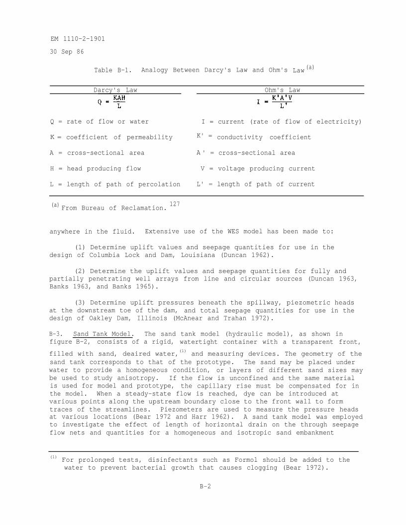
EM 1110-2-1901
30 Sep 86
Table B-1. Analogy Between Darcy's Law and Ohm's Law (a)
Darcy's Law Ohm's Law
Q = rate of flow or water I = current (rate of flow of electricity)
K = coefficient of permeability K' = conductivity coefficient
A = cross-sectional area A ' = cross-sectional area
H = head producing flow V = voltage producing current
L = length of path of percolation L' = length of path of current
(a) From Bureau of Reclamation.127
anywhere in the fluid. Extensive use of the WES model has been made to:
(1) Determine uplift values and seepage quantities for use in thedesign of Columbia Lock and Dam, Louisiana (Duncan 1962).
(2) Determine the uplift values and seepage quantities for fully andpartially penetrating well arrays from line and circular sources (Duncan 1963,Banks 1963, and Banks 1965).
(3) Determine uplift pressures beneath the spillway, piezometric headsat the downstream toe of the dam, and total seepage quantities for use in thedesign of Oakley Dam, Illinois (McAnear and Trahan 1972).
B-3. Sand Tank Model. The sand tank model (hydraulic model), as shown infigure B-2, consists of a rigid, watertight container with a transparent front,
filled with sand, deaired water,(1) and measuring devices. The geometry of thesand tank corresponds to that of the prototype. The sand may be placed underwater to provide a homogeneous condition, or layers of different sand sizes maybe used to study anisotropy. If the flow is unconfined and the same materialis used for model and prototype, the capillary rise must be compensated for inthe model. When a steady-state flow is reached, dye can be introduced atvarious points along the upstream boundary close to the front wall to formtraces of the streamlines. Piezometers are used to measure the pressure headsat various locations (Bear 1972 and Harr 1962). A sand tank model was employedto investigate the effect of length of horizontal drain on the through seepageflow nets and quantities for a homogeneous and isotropic sand embankment
(1) For prolonged tests, disinfectants such as Formol should be added to thewater to prevent bacterial growth that causes clogging (Bear 1972).
B-2
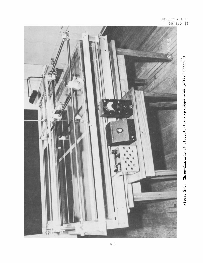
EM 1110-2-190130 Sep 86
B-3
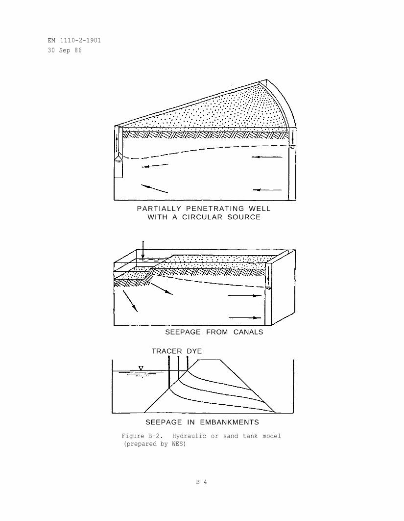
EM 1110-2-1901
30 Sep 86
PARTIALLY PENETRATING WELLWITH A CIRCULAR SOURCE
SEEPAGE FROM CANALS
TRACER DYE
SEEPAGE IN EMBANKMENTS
Figure B-2. Hydraulic or sand tank model(prepared by WES)
B-4
EM 1110-2-1901
30 Sep 86
(Brand and Armstrong 1968). Sand tank models are also used extensively inpetroleum engineering, ground-water quality, and pollution research (Bear 1972and Prickett 1979).
B-4. Viscous Flow Models. The viscous flow model, also called the Hele-Shawor parallel plate model, is based on the similarity between the differentialequations governing saturated flow in a porous medium and those describing theflow of a viscous liquid in the narrow space between two parallel plates. Theviscous flow model contains the shape of the structure to be Investigated andonce a steady-state flow is obtained, colored dyes can be injected along theupstream edge and patterns of streamlines can be observed. A camera (movie orstill) is normally used to record the results of experiments. Inhomogeneoushydraulic conductivity, such as would exist in a zoned earth dam, can be simu-lated by varying the width of the interspace between the parallel plates, asshown in figure B-3. The viscous flow model experiments should be conducted ina temperature-controlled room because viscosity plays an important role inanalog scaling. If this is not feasible, the temperature should be measured atall inflow and outflow points during the test and scales must be recomputedaccording to the varying average temperature of the liquid in the model (Bear1972 and Harr 1962). A viscous flow model was constructed at WES to simulateseepage conditions induced in streambanks by sudden drawdown of the river level.The results from the model study compared favorably with field observations,finite difference, and finite element methods (Desai 1970 and Desai 1973).
B-5. Method of Fragments.
a. General. The method of fragments is an approximate analyticalmethod for the computation of flows and pressure heads for any ground-watersystem. The underlying assumption of this procedure developed by Pavlovsky in1935 (Pavlovsky 1956 and Harr 1962) is that equipotential lines at variouscritical locations in the flow region can be approximated by straight verticallines. These equipotential lines divide the flow region into parts or frag-ments. Other assumptions inherent in the method of fragments procedure are(a) Darcy's law is valid, (b) steady-state flow exists, and (c) the soil mediumis approximated as a single homogeneous and isotropic layer or at series ofsuch layers. The transformation of anisotropic soil to an equivalent isotropicsoil is described in Section 4.7 of this manual.
b. Basic Concepts. The quantity of flow through a single fragment iscomputed as:
(B-1)
where
k - coefficient of permeability
hi = head loss through the fragment
= dimensionless form factor, = Ne/Nf
B-5
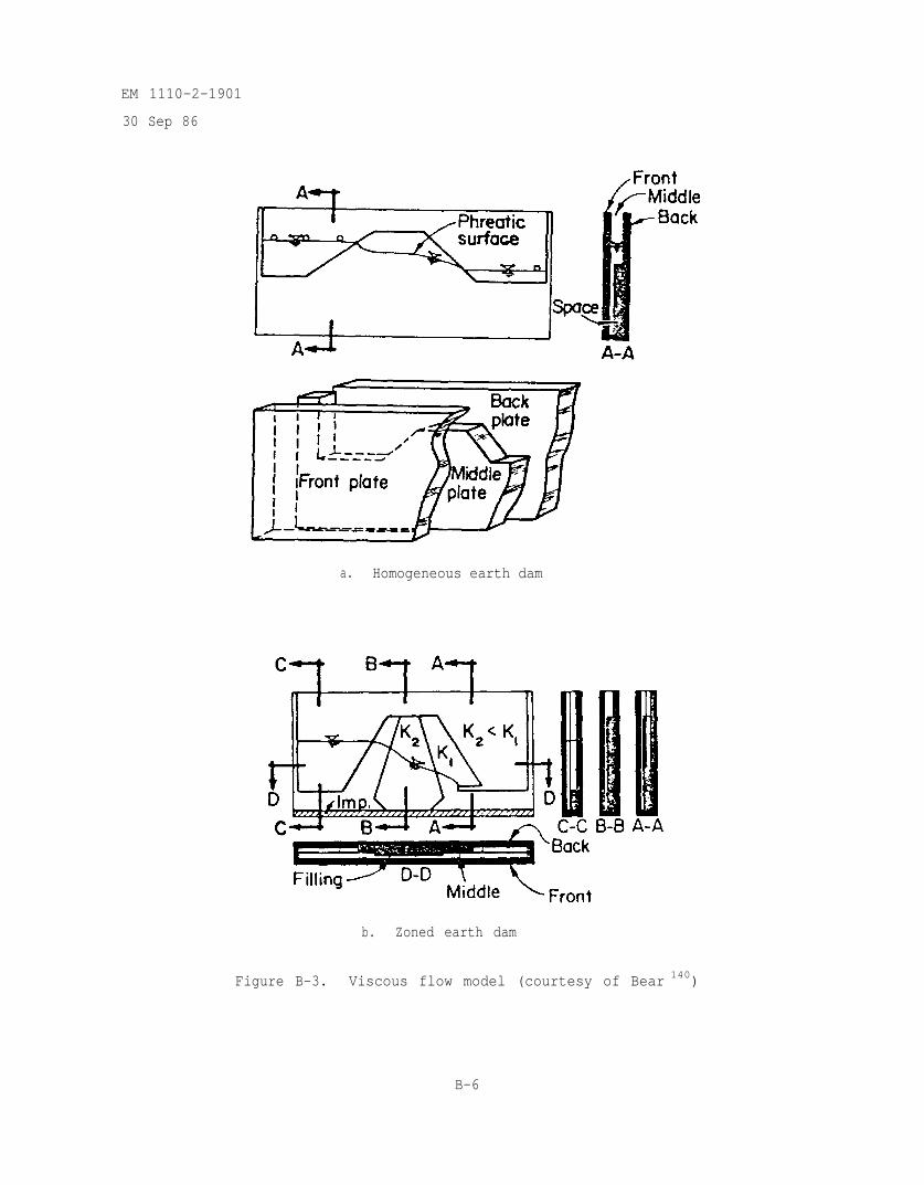
EM 1110-2-1901
30 Sep 86
a. Homogeneous earth dam
b. Zoned earth dam
Figure B-3. Viscous flow model (courtesy of Bear 140)
B-6
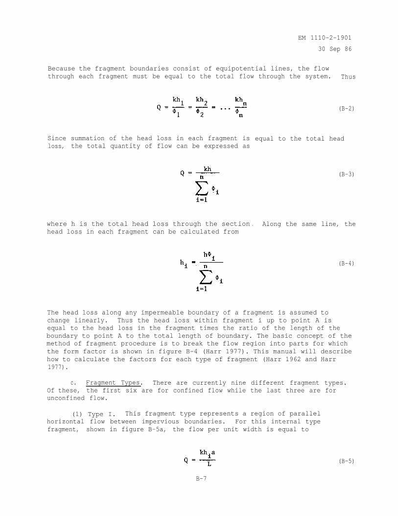
EM 1110-2-1901
30 Sep 86
Because the fragment boundaries consist of equipotential lines, the flowthrough each fragment must be equal to the total flow through the system. Thus
Since summation of the head loss in each fragment isloss, the total quantity of flow can be expressed as
where h is the total head loss through the sectionhead loss in each fragment can be calculated from
. Along the same line, the
(B-2)
equal to the total head
(B-3)
(B-4)
The head loss along any impermeable boundary of a fragment is assumed tochange linearly. Thus the head loss within fragment i up to point A isequal to the head loss in the fragment times the ratio of the length of theboundary to point A to the total length of boundary. The basic concept of themethod of fragment procedure is to break the flow region into parts for whichthe form factor is shown in figure B-4 (Harr 1977). This manual will describehow to calculate the factors for each type of fragment (Harr 1962 and Harr1977).
c. Fragment Types. There are currently nine different fragment types.Of these, the first six are for confined flow while the last three are forunconfined flow.
(1) Type I. This fragment type represents a region of parallelhorizontal flow between impervious boundaries. For this internal typefragment, shown in figure B-5a, the flow per unit width is equal to
(B-5)
B-7
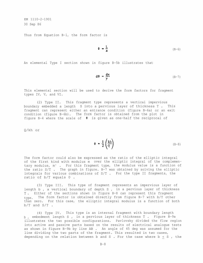
EM 1110-2-1901
30 Sep 86
Thus from Equation B-l, the form factor is
An elemental Type I section shown in figure B-5b illustrates that
(B-6)
(B-7)
This elemental section will be used to derive the form factors for fragmenttypes IV, V, and VI.
(2) Type II. This fragment type represents a vertical imperviousboundary embedded a length S into a pervious layer of thickness T . Thisfragment can represent either an entrance condition (figure B-6a) or an exitcondition (figure B-6b). The form factor is obtained from the plot infigure B-4 where the scale of is given as one-half the reciprocal of
Q/kh or
(B-8)
The form factor could also be expressed as the ratio of the elliptic integralof the first kind with modulus m over the elliptic integral of the complemen-tary modulus, m' . For this fragment type, the modulus value is a function ofthe ratio S/T . The graph in figure. B-7 was obtained by solving the ellipticintegrals for various combinations of S/T . For the type II fragments, theratio of b/T equals 0 .
(3) Type III. This type of fragment represents an impervious layer oflength b , a vertical boundary of depth S , in a pervious layer of thicknessT . Either of the sections shown in figure B-8 can represent this fragmenttype. The form factor is obtained directly from figure B-7 with b/T otherthan zero. For this case, the elliptic integral modulus is a function of bothb/T and S/T .
(4) Type IV. This type is an internal fragment with boundary lengthb , embedment length S , in a pervious layer of thickness T . Figure B-9aillustrates the two possible configurations. Pavlovsky divided the flow regioninto active and passive parts based on the results of electrical analogue testsas shown in figure B-9b by line AB . An angle of 45 deg was assumed for theline dividing the two parts of the fragment. This resulted in two cases,depending on the relation between b and S . For the case where b < S , the
B-8
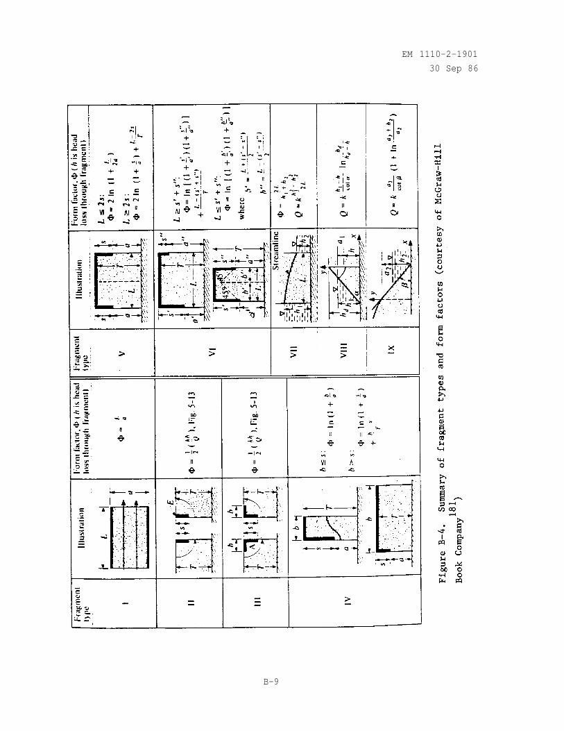
EM 1110-2-1901
30 Sep 86
B-9
EM 1110-2-1901
30 Sep 86
Figure B-5. Type I fragment (courtesy of McGraw-Hill
Book Company181
)
Figure B-6. Type II fragment (courtesy of McGraw-Hill
Book Company181
)
B-10
EM 1110-2-1901
30 Sep 86
Figure B-7. Quantity of discharge for symmetricallyplaced pilings (courtesy of McGraw-Hill Book
181Company )
B-11
EM 1110-2-1901
30 Sep 86
(a) (b)
Figure B-8. Type III fragment (courtesy of McGraw-Hill
Book Company 181 )
active zone is composed of elements of type I fragments of width dx illus-trated in figure B-9c. The form factor is the integral of dx over y from0 to b which results in a form factor of
(B-9)
If b > S, then the fragment can be divided into two fragments as shown infigure B-9e. The first is a type IV with b > S and the second is a type Ifragment with L equal to b - S . Thus the form factor is the sum of theform factors which would be
(B-10)
(5) Type V. This fragment type has two vertical boundaries of equalembedment S in a pervious layer of thickness T . As shown in figure B-10,the form factor for this fragment is twice that for the type IV fragment.
B-12
EM 1110-2-1901
30 Sep 86
Figure B-9. Type IV fragment (courtesy of McGraw-Hill Book181
Company )
B-13
EM 1110-2-1901
30 Sep 86
Figure B-10. Type V fragment (courtesy of McGraw-Hill
Book Company 181)
Since there were two cases of type IV fragment, there are two cases for thetype V fragment. The two cases are for L < 2s and L > 2S . For the firstcase, the form factor is
(B-11)
For the second case which consists of a type I fragment within two type IVfragments, the form factor is
(B-12)
(6) Type VI. This fragment type, illustrated in figure B-11, is thesame as the type V fragment except that the embedment lengths are different.Using the same approximations as in fragment type IV, there are two cases forthe form factor. For the first case where L > (S' + S"), the form factor is
(B-13)
B-14
EM 1110-2-1901
30 Sep 86
Figure B-11. Type VI fragment (courtesy of McGraw-Hill
Book Company 181)
For the second case where L < (S' + S"), the form factor is
(B-14)
where
(7) Type VII. This fragment represents the condition of unconfinedflow. This flow is characterized by having one boundary of the flow domain asa free surface (line AB in figure B-12). This free surface separates thesaturated region from that region where no flow occurs. From Darcy's law andDupuit's assumptions, the hydraulic gradient is (h1 - h2)/L and thecross-sectional area is (h1 + h2)/2 , thus the flow is
(B-15)
B-15
EM 1110-2-1901
30 Sep 86
Figure B-12. Type VII fragment (courtesy of McGraw-Hill
Book Company181
)
From this, the form factor is
(B-16)
(8) Type VIII. This fragment type represents an upstream slopeentrance condition on an earth dam of height hd and is illustrated infigure B-13. It was assumed that the curve streamlines (cd) could beapproximated by horizontal flow channels of length ed (Pavlovsky 1956 andHarr 1977). With this assumption, the hydraulic gradient in each channel is
(B-17)
B-16
EM 1110-2-1901
30 Sep 86
Figure B-13. Type VIII fragment (courtesy of McGraw-Hill
Book Company 181)
Integrating the ratio dy/(hd - y) fromfor the quantity of flow as
0 to h generates the expression
(B-18)
(9) Type IX. This fragment type, shown in figure B-14, represents theexit condition where the surface of seepage exists.(DE) is not an equipotential line or a streamline.
The surface of seepagePavlovsky assumed that the
flow is horizontal. For the portion of the slope between D and E , theflow is the coefficient of permeability times the integral of dy overcot The flow fora2dy over the cot
E to F is the permeability times the integral of
expression for the flow is(a2 + h2 - y) . When the integration is performed, the
(B-19)
B-17
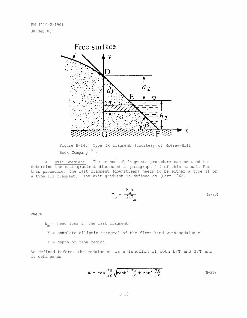
EM 1110-2-1901
30 Sep 86
Figure B-14. Type IX fragment (courtesy of McGraw-Hill
Book Company181
)
d. Exit Gradient. The method of fragments procedure can be used todetermine the exit gradient discussed in paragraph 4.9 of this manual. Forthis procedure, the last fragment (downstream) needs to be either a type II ora type III fragment. The exit gradient is defined as (Harr 1962)
(B-20)
where
hm
= head loss in the last fragment
K = complete elliptic integral of the first kind with modulus m
T = depth of flow region
As defined before, the modulus m is a function of both b/T and S/T andis defined as
(B-21)
B-18
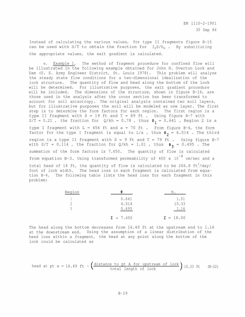
EM 1110-2-1901
30 Sep 86
Instead of calculating the various values, for type II fragments figure B-15can be used with S/T to obtain the fraction for IES/hm . By substituting
the appropriate values, the exit gradient is calculated.
e. Example 1. The method of fragment procedure for confined flow willbe illustrated in the following example obtained for John H. Overton Lock andDam (U. S. Army Engineer District, St. Louis 1978). This problem will analyzethe steady state flow conditions for a two-dimensional idealization of thelock structure. The quantity of flow and head along the bottom of the lockwill be determined. For illustrative purposes, the exit gradient procedurewill be included. The dimensions of the structure, shown in figure B-16, arethose used in the analysis after the cross section has been transformed toaccount for soil anisotropy. The original analysis contained two soil layers,but for illustrative purposes the soil will be modeled as one layer. The firststep is to determine the form factors for each region. The first region is atype II fragment with S = 19 ft and T = 89 ft . Using figure B-7 withS/T = 0.21 , the fraction for Q/kh = 0.78 , thus = 0.641 . Region 2 is a
type I fragment with L = 456 ft and a = 70 ft . From figure B-4, the formfactor for the type I fragment is equal to L/a , thus = 6.514 . The third
region is a type II fragment with S = 9 ft and T = 79 ft . Using figure B-7with S/T = 0.114 , the fraction for Q/kh = 1.01 , thus = 0.495 . The
summation of the form factors is 7.650. The quantity of flow is calculated
from equation B-3. Using transformed permeability of 400 x 10-4
cm/sec and a
total head of 18 ft, the quantity of flow is calculated to be 266.8 ft3/day/foot of lock width. The head loss in each fragment is calculated from equa-tion B-4. The following table lists the head loss for each fragment in thisproblem:
Region hi
1 0.641 1.512 6.514 15.333 0.495 1.16
= 7.650 = 18.00
The head along the bottom decreases from 16.49 ft at the upstream end to 1.16at the downstream end. Using the assumption of a linear distribution of thehead loss within a fragment, the head at any point along the bottom of thelock could be calculated as
head at pt a = 16.49 ft - distance to pt A for upstream of locktotal length of lock 15.33 ft (B-22)
B-19
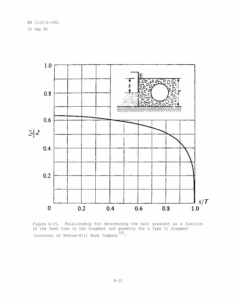
EM 1110-2-1901
30 Sep 86
Figure B-15. Relationship for determining the exit gradient as a functionof the head loss in the fragment and geometry for a Type II fragment
(courtesy of McGraw-Hill Book Company181
)
B-20
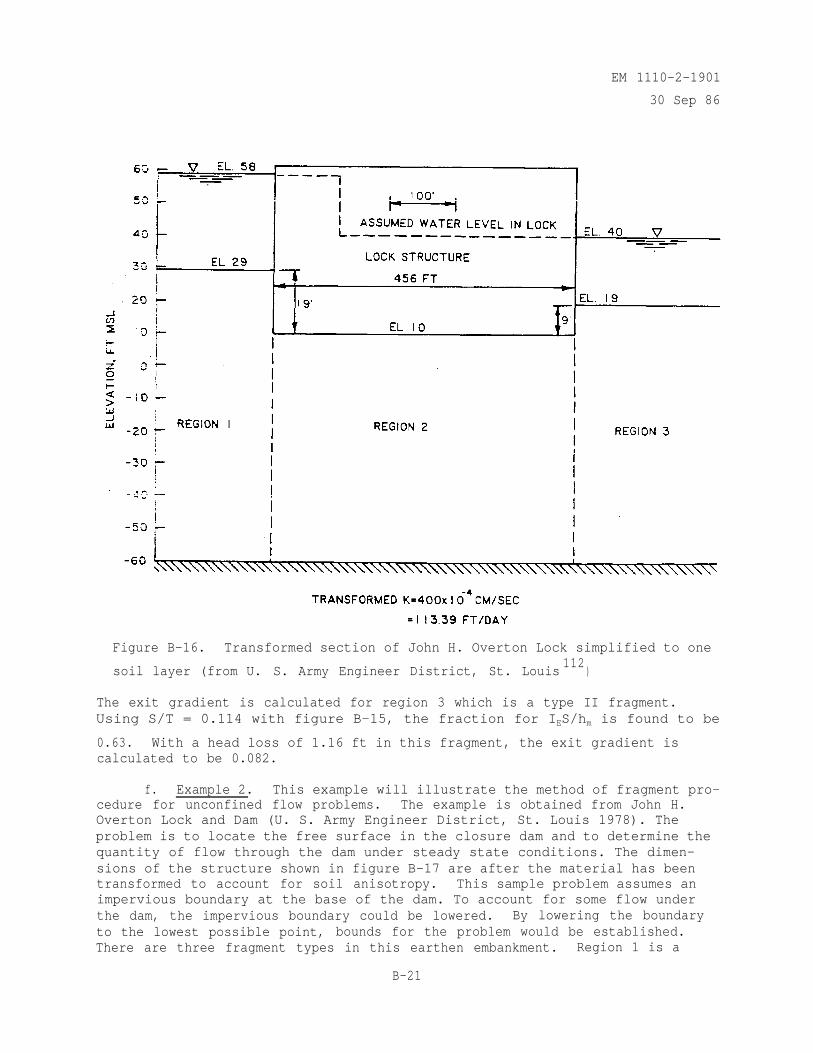
EM 1110-2-1901
30 Sep 86
Figure B-16. Transformed section of John H. Overton Lock simplified to one
soil layer (from U. S. Army Engineer District, St. Louis112
)
The exit gradient is calculated for region 3 which is a type II fragment.Using S/T = 0.114 with figure B-15, the fraction for IES/hm is found to be
0.63. With a head loss of 1.16 ft in this fragment, the exit gradient iscalculated to be 0.082.
f. Example 2. This example will illustrate the method of fragment pro-cedure for unconfined flow problems. The example is obtained from John H.Overton Lock and Dam (U. S. Army Engineer District, St. Louis 1978). Theproblem is to locate the free surface in the closure dam and to determine thequantity of flow through the dam under steady state conditions. The dimen-sions of the structure shown in figure B-17 are after the material has beentransformed to account for soil anisotropy. This sample problem assumes animpervious boundary at the base of the dam. To account for some flow underthe dam, the impervious boundary could be lowered. By lowering the boundaryto the lowest possible point, bounds for the problem would be established.There are three fragment types in this earthen embankment. Region 1 is a
B-21
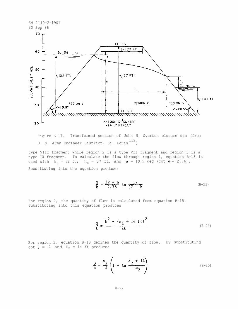
EM 1110-2-190130 Sep 86
Figure B-17. Transformed section of John H. Overton closure dam (from
U. S. Army Engineer District, St. Louis112
)
type VIII fragment while region 2 is a type VII fragment and region 3 is atype IX fragment. To calculate the flow through region 1, equation B-18 isused with h
i= 32 ft; hd = 37 ft, and = 19.9 deg (cot = 2.76).
Substituting into the equation produces
For region 2, the quantity of flow is calculated from equation B-15.Substituting into this equation produces
(B-23)
(B-24)
For region 3, equation B-19 defines the quantity of flow. By substitutingcot = 2 and H2 = 14 ft produces
(B-25)
B-22
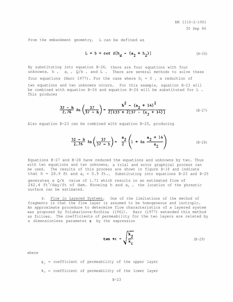
EM 1110-2-1901
30 Sep 86
From the embankment geometry, L can be defined as
(B-26)
By substituting into equation B-26, there are four equations with fourunknowns, h , a2 , Q/k , and L . There are several methods to solve these
four equations (Harr 1977). For the case where h2 = 0 , a reduction of
two equations and two unknowns occurs. For this example, equation B-23 willbe combined with equation B-24 and equation B-26 will be substituted for L .This produces
Also equation B-23 can be combined with equation B-25, producing
(B-27)
(B-28)
Equations B-27 and B-28 have reduced the equations and unknowns by two. Thuswith two equations and two unknowns, a trial and error graphical process canbe used. The results of this process are shown in figure B-18 and indicatethat h = 28.9 ft and a2 = 0.9 ft., Substituting into equations B-23 and B-25
generates a Q/k value of 1.71 which results in an estimated flow of242.4 ft3/day/ft of dam. Knowing h and a2 , the location of the phreaticsurface can be estimated.
g. Flow in Layered Systems. One of the limitations of the method offragments is that the flow layer is assumed to be homogeneous and isotropic.An approximate procedure to determine flow characteristics of a layered systemwas proposed by Polubarinova-Kochina (1941). Harr (1977) extended this methodas follows. The coefficients of permeability for the two layers are related bya dimensionless parameter by the expression
where
(B-29)
k1 = coefficient of permeability of the upper layer
k2 = coefficient of permeability of the lower layer
B-23
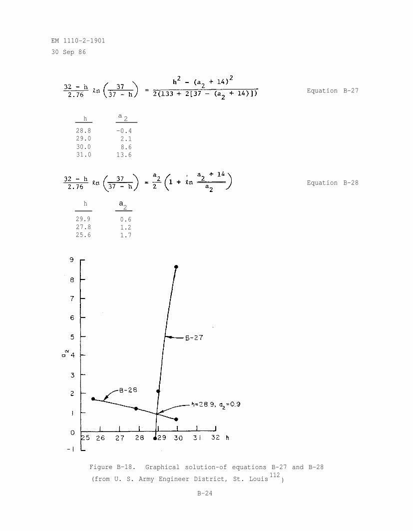
EM 1110-2-1901
30 Sep 86
h a 2
28.8 -0.429.0 2.130.0 8.631.0 13.6
h a2
29.9 0.627.8 1.225.6 1.7
Equation B-27
Equation B-28
Figure B-18. Graphical solution-of equations B-27 and B-28
(from U. S. Army Engineer District, St. Louis112
)
B-24
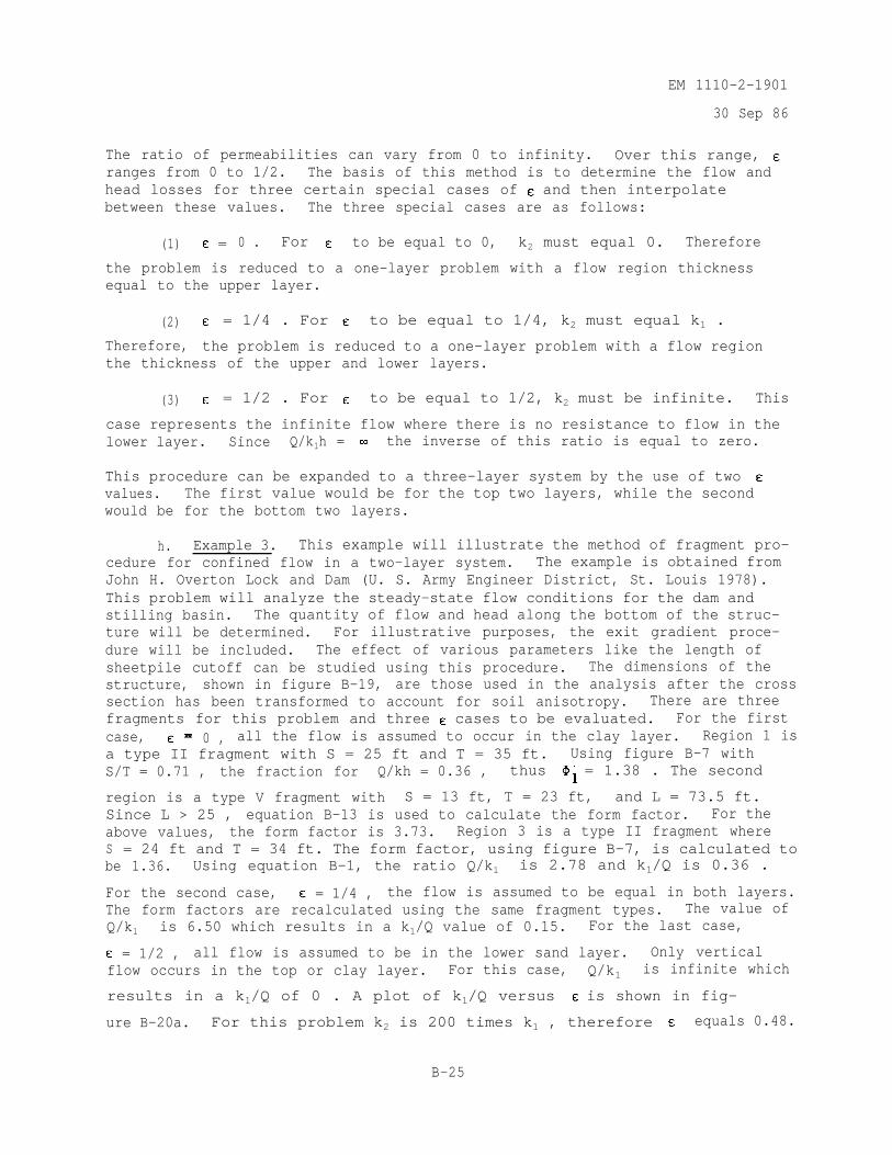
EM 1110-2-1901
30 Sep 86
The ratio of permeabilities can vary from 0 to infinity. Over this range,ranges from 0 to 1/2. The basis of this method is to determine the flow andhead losses for three certain special cases of and then interpolatebetween these values. The three special cases are as follows:
(1) = 0 . For to be equal to 0, k2 must equal 0. Therefore
the problem is reduced to a one-layer problem with a flow region thicknessequal to the upper layer.
(2) = 1/4 . For to be equal to 1/4, k2 must equal k1 .
Therefore, the problem is reduced to a one-layer problem with a flow regionthe thickness of the upper and lower layers.
(3) = 1/2 . For to be equal to 1/2, k2 must be infinite. This
case represents the infinite flow where there is no resistance to flow in thelower layer. Since Q/k1h = the inverse of this ratio is equal to zero.
This procedure can be expanded to a three-layer system by the use of twovalues. The first value would be for the top two layers, while the secondwould be for the bottom two layers.
h. Example 3. This example will illustrate the method of fragment pro-cedure for confined flow in a two-layer system. The example is obtained fromJohn H. Overton Lock and Dam (U. S. Army Engineer District, St. Louis 1978).This problem will analyze the steady-state flow conditions for the dam andstilling basin. The quantity of flow and head along the bottom of the struc-ture will be determined. For illustrative purposes, the exit gradient proce-dure will be included. The effect of various parameters like the length ofsheetpile cutoff can be studied using this procedure. The dimensions of thestructure, shown in figure B-19, are those used in the analysis after the crosssection has been transformed to account for soil anisotropy. There are threefragments for this problem and three cases to be evaluated. For the firstcase, 0 , all the flow is assumed to occur in the clay layer. Region 1 isa type II fragment with S = 25 ft and T = 35 ft. Using figure B-7 withS/T = 0.71 , the fraction for Q/kh = 0.36 , thus = 1.38 . The second
region is a type V fragment with S = 13 ft, T = 23 ft, and L = 73.5 ft.Since L > 25 , equation B-13 is used to calculate the form factor. For theabove values, the form factor is 3.73. Region 3 is a type II fragment whereS = 24 ft and T = 34 ft. The form factor, using figure B-7, is calculated tobe 1.36. Using equation B-1, the ratio Q/k1 is 2.78 and k1/Q is 0.36 .
For the second case, = 1/4 , the flow is assumed to be equal in both layers.The form factors are recalculated using the same fragment types. The value ofQ/k1 is 6.50 which results in a k1/Q value of 0.15. For the last case,
= 1/2 , all flow is assumed to be in the lower sand layer. Only verticalflow occurs in the top or clay layer. For this case, Q/k1 is infinite which
results in a k1/Q of 0 . A plot of k1/Q versus is shown in fig-
ure B-20a. For this problem k2 is 200 times k1 , therefore equals 0.48.
B-25
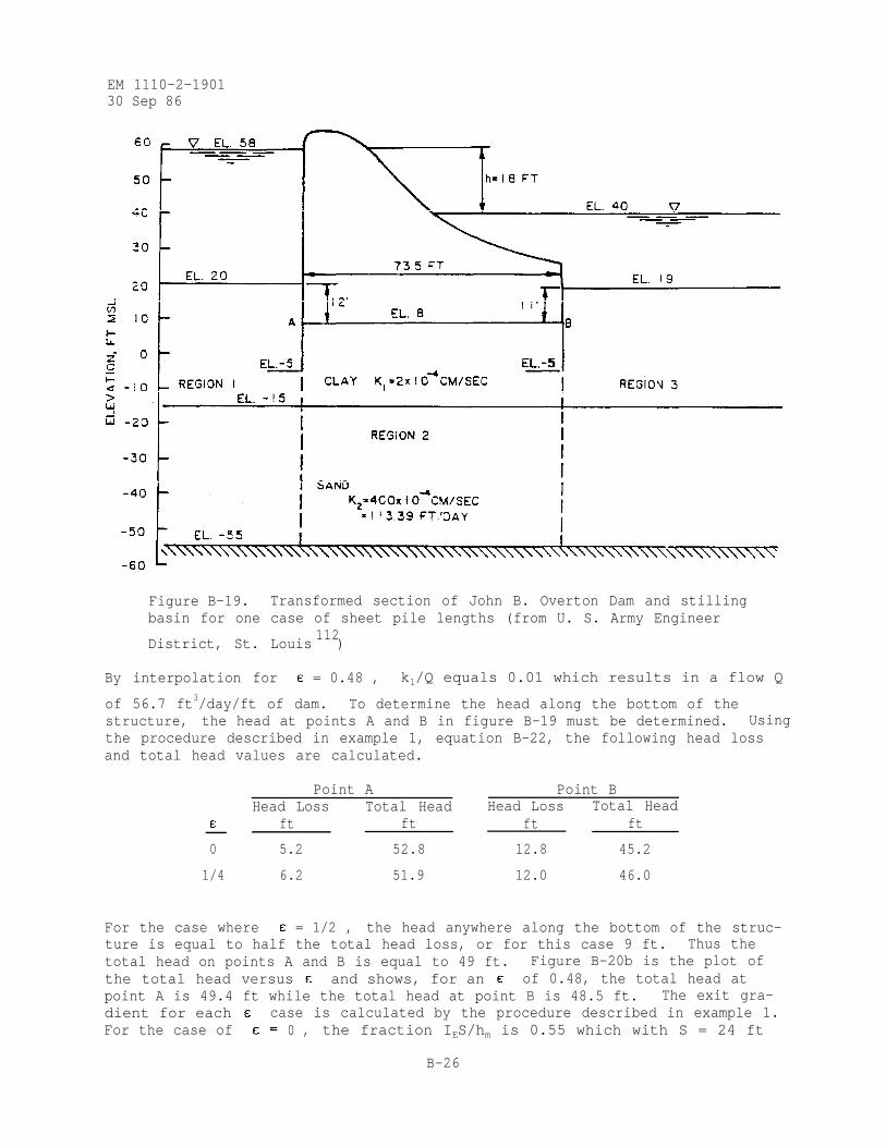
EM 1110-2-190130 Sep 86
Figure B-19. Transformed section of John B. Overton Dam and stillingbasin for one case of sheet pile lengths (from U. S. Army Engineer
District, St. Louis112
)
By interpolation for = 0.48 , k1/Q equals 0.01 which results in a flow Q
of 56.7 ft3/day/ft of dam. To determine the head along the bottom of thestructure, the head at points A and B in figure B-19 must be determined. Usingthe procedure described in example 1, equation B-22, the following head lossand total head values are calculated.
Point A Point BHead Loss Total Head Head Loss Total Head
ft ft ft ft
0 5.2 52.8 12.8 45.2
1/4 6.2 51.9 12.0 46.0
For the case where = 1/2 , the head anywhere along the bottom of the struc-ture is equal to half the total head loss, or for this case 9 ft. Thus thetotal head on points A and B is equal to 49 ft. Figure B-20b is the plot ofthe total head versus and shows, for an of 0.48, the total head atpoint A is 49.4 ft while the total head at point B is 48.5 ft. The exit gra-dient for each case is calculated by the procedure described in example 1.For the case of 0 , the fraction IES/hm is 0.55 which with S = 24 ft
B-26
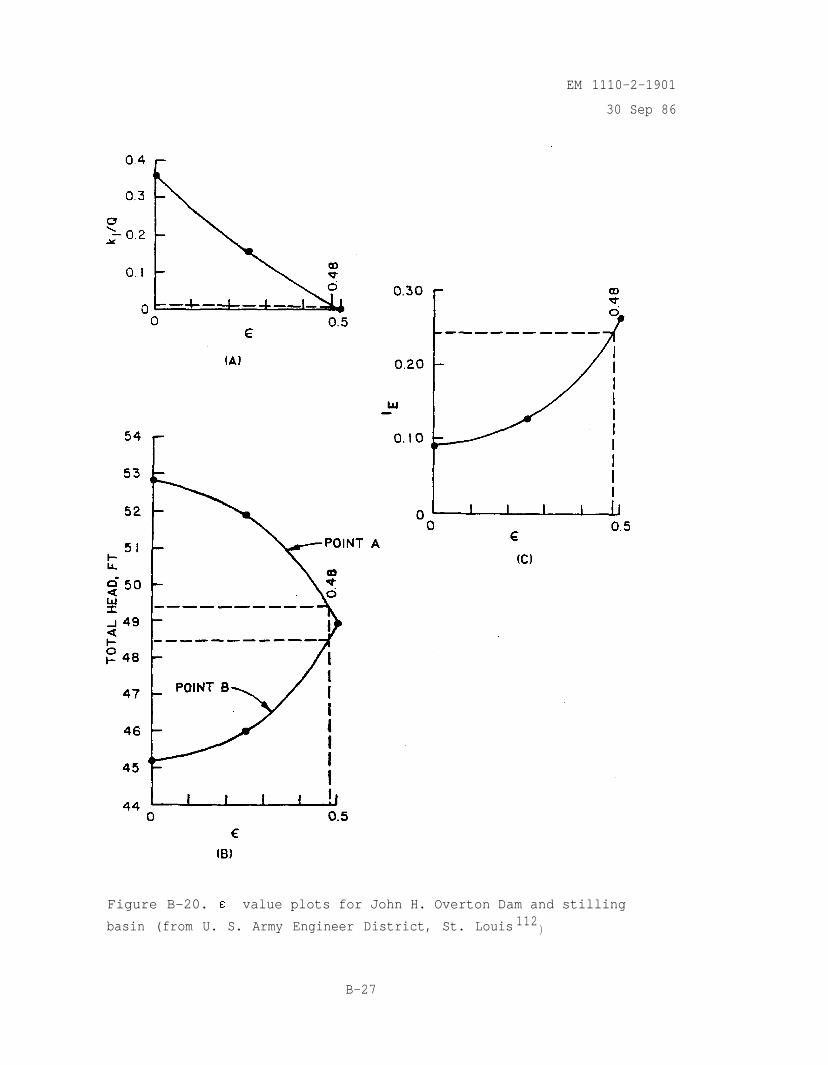
EM 1110-2-1901
30 Sep 86
Figure B-20. value plots for John H. Overton Dam and stilling
basin (from U. S. Army Engineer District, St. Louis 112)
B-27
EM 1110-2-1901
30 Sep 86
and hm
IES/hm
= 3.8 ft produces IE =
is 0.615 which with S =
IE = 0.128 . For the case where
the distance is the thickness of
0.087 . For the = 1/4 case, the fraction
24 ft and hm = 5.0 ft produces
= 1/2 , the head loss is the total head and
the top layer. Using the equation
the exit gradient is 0.265. The exit gradient versus plot is shown infigure B-20c. For an value of 0.48, the exit gradient is 0.245.
(B-30)
i. Uses and Limitations. The method of fragment procedure should beused as a design tool where various factors are changed to evaluate theireffect or as an analytical tool when quick approximate results are needed.When numerous factors are varied, the construction of flow nets becomes verytedious and time consuming. The method of fragment procedure will generatereasonable results for problems where the assumptions are not greatly violated.There are several points the user needs to be aware of when using this proce-dure. The flow region must be generalized so that it consists of horizontaland vertical boundaries. The procedure models the actual flow paths withinthe flow region, thus if there is any doubt as to the direction, a rough flownet should be drawn. This becomes important when a small portion of a struc-ture is modeled with several fragments because the flow could be modeled inunnatural paths. The accuracy of the results is dependent upon how well thefragment boundary actually represents vertical equipotential lines. Thegreater the deviation, the greater the degree of error. However, for manypractical problems reasonable results are generated. Comparison of the methodof fragment results with finite element solutions for a one-layer systemshowed that the quantity of flow values for the fragment procedure are within8 percent of the finite element results, while the uplift values are within38 percent of the finite element results. The Computer-Aided Structural Engi-neering (CASE) project has developed a computer program for the method offragments procedure with a user manual describing the program (Pace et al.1984).
B-6. Finite Difference Method.
a. Method of Solution. As previously mentioned in Chapter 4, thefinite difference method solves the Laplace equations by approximating themwith a set of linear algebraic expressions. The approximation is mathematicalrather than physical. The early methods of solving finite difference expres-sions for Laplace's equation were based upon hand calculations by the relaxa-
tion method(1). However, more recently a wide range of finite differencesolutions suited to the digital computer have been developed. A description of
(1) For example, see Appendix A of EM 1110-2-2501.
B-28
EM 1110-2-1901
30 Sep 86
available methods used to solve finite difference problems including exampleapplications, case studies, and computer program listings is available (Rushtonand Redshaw 1979).
b. Advantages. Use of iterative techniques such as successive over-relaxation which converge to the correct solution allows solution of uncon-fined and transient flow problems, For simple problems, the finite differencemethod is usually more economical than the finite element method (Rushton andRedshaw 1979).
c. Disadvantages. The finite difference method is not suited to com-plex geometry, including sloping layers and pockets of materials of varyingpermeability. Irregular grids are difficult to input. Therefore, zones whereseepage gradients or velocities are high cannot be accurately modeled (Rushtonand Redshaw 1979).
d. Applications. The finite difference method was used at WES to simu-late seepage conditions in streambanks induced by sudden drawdown of the riverlevel. As mentioned previously, this study included a viscous flow model,field observations, and application of the finite element and finite differ-ence methods. The results of the study indicated that the finite differencemethod provided satisfactory and economical solutions for transient unconfinedfluid flow in porous, anisotropic, and nonhomogeneous media (Desai 1970 andDesai 1973). The finite difference method was used to predict the location ofthe phreatic surface within a zoned embankment with arbitrary fluctuations ofthe reservoir (Dvinoff 1970). Generalized digital computer programs have beendeveloped which use the finite difference method to simulate one-, two-, andthree-dimensional nonsteady flow problems in heterogeneous aquifers underwater table and artesian conditions (Prickett and Lonnquist 1971 and Desai1977). The finite difference method has been used to predict unsteady flow ingravity wells. Good agreement was found between computed results andlaboratory test results obtained using a sand tank model (Desai 1977).
B-7. Finite Element Method.
a. Method of Solution. As previously mentioned in Chapter 4, thefinite element method is conceptually a physical rather than a mathematicalapproximation. The flow region is subdivided into a number of elements andpermeabilities are specified for each element. Boundary conditions are speci-fied in terms of heads and flow rates and a system of equations is solved tocompute gradients and velocities in each element (Desai and Abel 1972 and Desai1977). Two- and three-dimensional finite element seepage computer programs forboth confined and unconfined flow problems have been developed at WES. Steady-state and transient problems (that can be treated as a series of steady-stateproblems) can be solved (Tracy 1973a; Tracy 1973b; and Hall, Tracy, andRadhakrishnan 1975). An interactive graphics preprocessor is available togenerate the finite element grid (Tracy 1977a). It is possible to compute thestream function and potential and plot contours of these values to obtain theflow net (Christian 1980 and Christian 1980). Details concerning the selectionof spatial and time meshes, computer time required, convergence, and stabilityare available (Desai 1977). Also, an interactive graphics postprocessor isavailable to assist in the analyses of the finite element results (Tracy
B-29
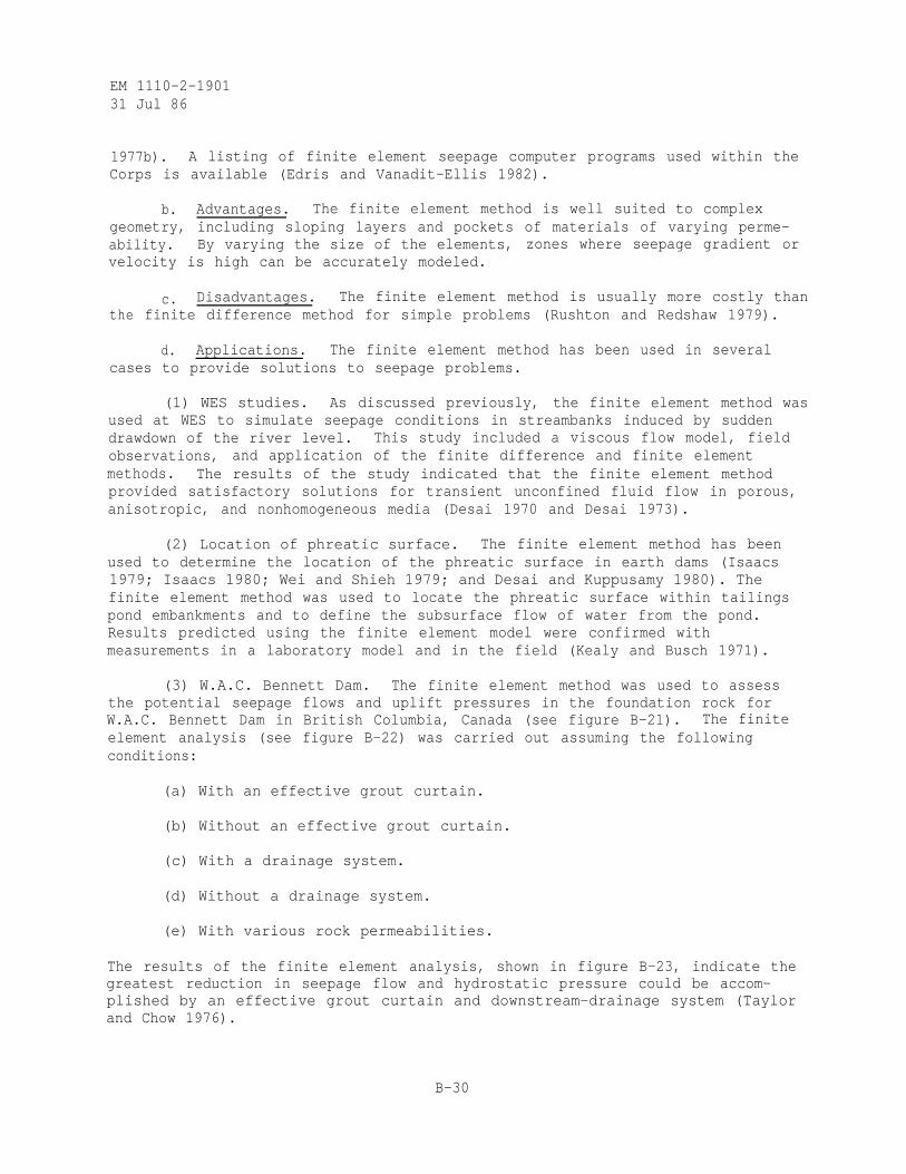
EM 1110-2-190131 Jul 86
1977b). A listing of finite element seepage computer programs used within theCorps is available (Edris and Vanadit-Ellis 1982).
b. Advantages. The finite element method is well suited to complexgeometry, including sloping layers and pockets of materials of varying perme-ability. By varying the size of the elements, zones where seepage gradient orvelocity is high can be accurately modeled.
c. Disadvantages. The finite element method is usually more costly thanthe finite difference method for simple problems (Rushton and Redshaw 1979).
d. Applications. The finite element method has been used in severalcases to provide solutions to seepage problems.
(1) WES studies. As discussed previously, the finite element method wasused at WES to simulate seepage conditions in streambanks induced by suddendrawdown of the river level. This study included a viscous flow model, fieldobservations, and application of the finite difference and finite elementmethods. The results of the study indicated that the finite element methodprovided satisfactory solutions for transient unconfined fluid flow in porous,anisotropic, and nonhomogeneous media (Desai 1970 and Desai 1973).
(2) Location of phreatic surface. The finite element method has beenused to determine the location of the phreatic surface in earth dams (Isaacs1979; Isaacs 1980; Wei and Shieh 1979; and Desai and Kuppusamy 1980). Thefinite element method was used to locate the phreatic surface within tailingspond embankments and to define the subsurface flow of water from the pond.Results predicted using the finite element model were confirmed withmeasurements in a laboratory model and in the field (Kealy and Busch 1971).
(3) W.A.C. Bennett Dam. The finite element method was used to assessthe potential seepage flows and uplift pressures in the foundation rock forW.A.C. Bennett Dam in British Columbia, Canada (see figure B-21). The finiteelement analysis (see figure B-22) was carried out assuming the followingconditions:
(a) With an effective grout curtain.
(b) Without an effective grout curtain.
(c) With a drainage system.
(d) Without a drainage system.
(e) With various rock permeabilities.
The results of the finite element analysis, shown in figure B-23, indicate thegreatest reduction in seepage flow and hydrostatic pressure could be accom-plished by an effective grout curtain and downstream-drainage system (Taylorand Chow 1976).
B-30
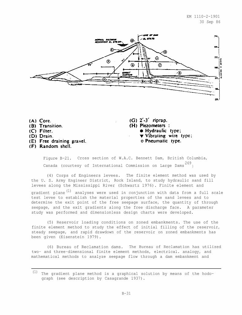
EM 1110-2-190130 Sep 86
Figure B-21. Cross section of W.A.C. Bennett Dam, British Columbia,
Canada (courtesy of International Commission on Large Dams269
)
(4) Corps of Engineers levees. The finite element method was used bythe U. S. Army Engineer District, Rock Island, to study hydraulic sand filllevees along the Mississippi River (Schwartz 1976). Finite element and
gradient plane (1) analyses were used in conjunction with data from a full scaletest levee to establish the material properties of the sand levees and todetermine the exit point of the free seepage surface, the quantity of throughseepage, and the exit gradients along the free discharge face. A parameterstudy was performed and dimensionless design charts were developed.
(5) Reservoir loading conditions on zoned embankments. The use of thefinite element method to study the effect of initial filling of the reservoir,steady seepage, and rapid drawdown of the reservoir on zoned embankments hasbeen given (Eisenstein 1979).
(6) Bureau of Reclamation dams. The Bureau of Reclamation has utilizedtwo- and three-dimensional finite element methods, electrical. analogy, andmathematical methods to analyze seepage flow through a dam embankment and
(1) The gradient plane method is a graphical solution by means of the hodo-graph (see description by Casagrande 1937).
B-31
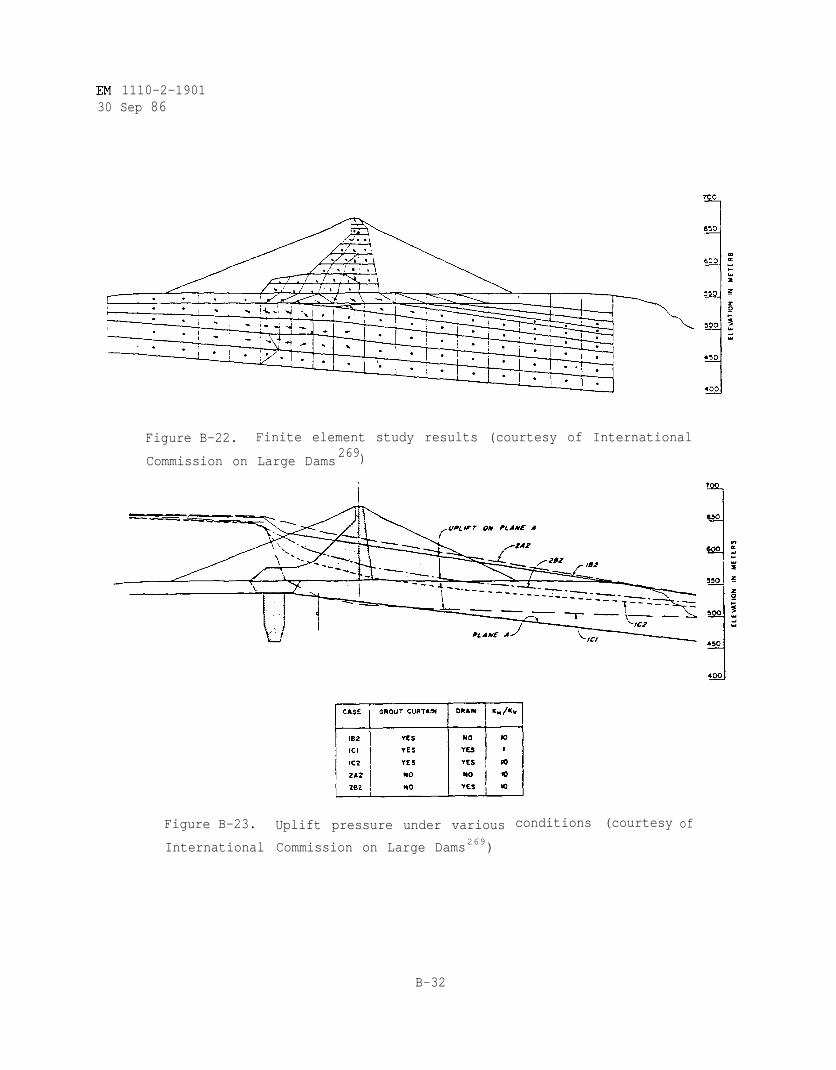
EM 1110-2-190130 Sep 86
Figure B-22. Finite element study results (courtesy of International
Commission on Large Dams269)
Figure B-23.
International
Uplift pressure under various
Commission on Large Dams269)
conditions (courtesy of
B-32
EM 111O-2-190130 Sep 86
foundation (Mantei and Harris 1979). Narrows Dam, Colorado, on the SouthPlatte River, was analyzed for seepage at the feasibility stage. Because of apervious foundation, the planners called for a positive vertical cutoff byconstructing a slurry wall down to the underlying shale. However, near theright abutment the shale drops away to depths too great for economical slurrywall construction. A three-dimensional finite element model (see figure B-24)was used to determine the vertical exit gradients at the downstream toe of thedam. The finite element method was used to study the effect of a toe drain,partial depth slurry trench, partially and fully penetrating relief wells (seefigure B-25). Calamus Dam, Nebraska, on the Calamus River, was also analyzedby the Bureau of Reclamation for seepage at the feasibility stage (Mantei andHarris 1979; Mantei, Esmiol, and Cobb 1980; Mantei and Cobb 1981; and Cobb1984). Calamus Dam has a setting very similar to Narrows Dam in the sense thatit is an earth dam on a pervious foundation. However, the underlying shale atCalamus Dam is at such a great depth that it cannot be used as the base for acutoff wall as it was for Narrows Dam. Early thinking on the project involvedthe use of a slurry trench cutoff down to a pervious sandstone fromation. Athree-dimensional finite element model (see figure B-26) was used to determinethe effects of an embankment toe drain, slurry trench under upstream blanket,and/or relief wells at the downstream toe of the dam on the seepage rates andhydraulic gradients in the dam foundation. Time and expense in operating thelarge three-dimensional finite element models made it necessary thatbe given to studying the various design alternatives using the best estimate
priority
of permeability for each foundation material rather than conducting sensitiv-ity studies to establish the effect of varying the permeability (see para-graph B-l). The three-dimensional finite element models were five elementsdeep, with the bottom layer of elements representing the sandstone, the nextlayer sand and gravel, recent alluvium, interbedded fine sand, and dune sand.A detailed three-dimensional finite element model was made for the outletworks area that defined more of the design details, such as the filter blanketunder the stilling basin and channel and water table elevation controls, tostudy the effectiveness of relief wells around the stilling basin.
(7) Corps of Engineer dams. The finite element method was used by the
U. S. Army Engineer District, Huntington,(1) in a reanalysis of the underseep-age at Bolivar Dam, Ohio, completed in 1938 on Sandy Creek (U. S. Army EngineerDistrict, Huntington 1977a). A two-dimensional finite element model (see fig-ure B-27) was used to determine the effects of an embankment toe drain, up-stream impervious blanket, and proposed relief wells on seepage quantities,exit gradients, and uplift pressures. A sensitivity study was conducted usingthe two-dimensional finite element model to determine the influence of variouspool and rock surface levels, the permeability ratio of foundation soils, theexistence of a downstream gravel layer, and the effective source of seepageentry upon underseepage. Typical test results for one set of boundary condi-tions and permeability values are given in figure B-28. Additional applica-tions of the two-dimensional finite element method to conduct sensitivityanalysis to assess the effect of permeability anisotropy and various seepagecontrol measures was given by Lefebvre and coworkers (Lefebvre, Part, and
(1) Work was performed by Soil Testing Services, Inc., Northbrook, Illinois.
B-33
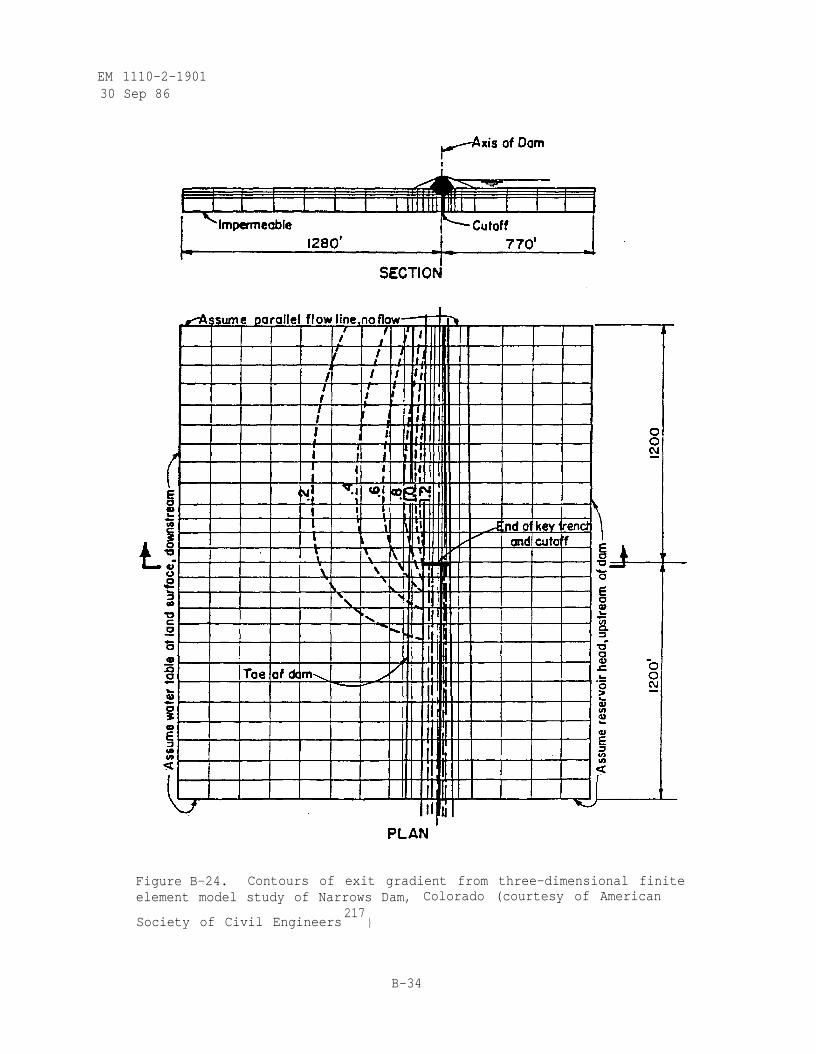
EM 1110-2-190130 Sep 86
Figure B-24. Contours of exit gradient from three-dimensional finiteelement model study of Narrows Dam, Colorado (courtesy of American
Society of Civil Engineers217
)
B-34
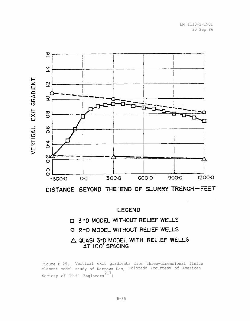
EM 1110-2-190130 Sep 86
Figure B-25. Vertical exit gradients from three-dimensional finiteelement model study of Narrows Dam, Colorado (courtesy of American
Society of Civil Engineers217
)
B-35

EM 1110-2-1901
30 Sep 86
Figure B-26. Grid for three-dimensional finite element modelstudy of Calamus Dam, Nebraska (courtesy of American Society
of Civil Engineers217
)
B-36
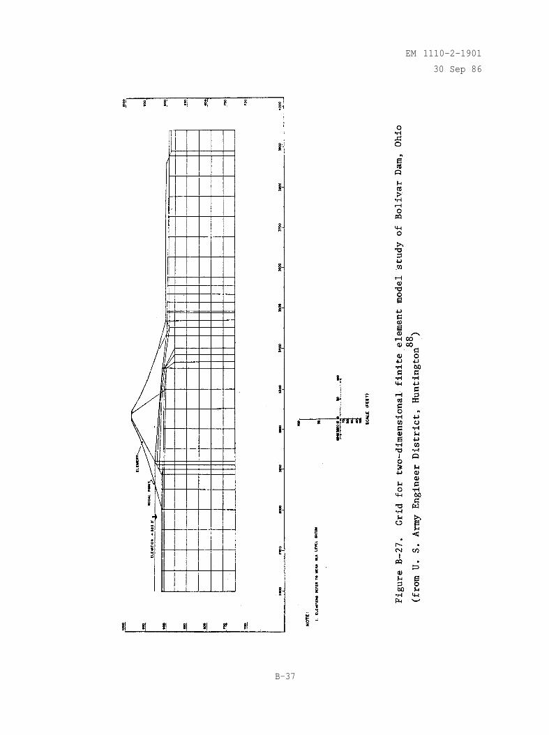
EM 1110-2-1901
30 Sep 86
B-37
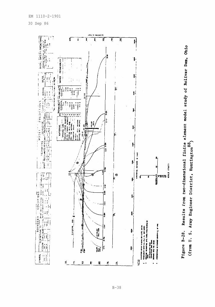
EM 1110-2-1901
30 Sep 86
B-38

EM 1110-2-1901
30 Sep 86
Tournier 1981). The finite element method was used by the U. S. Army Engineer
District, Huntington,(1) in a reanalysis of the underseepage at Mohawk Dam,Ohio, completed in 1937 on the Walhonding River (U. S. Army Engineer District,Huntington 1979b). A three-dimensional finite element model (see figure B-29)was used to study the cause of unusually high relief well flows. Typical testresults for one set of boundary conditions are given in figure B-30.
(1) Work was performed by Soil Testing Services, Inc., Northbrook, Illinois.
B-39
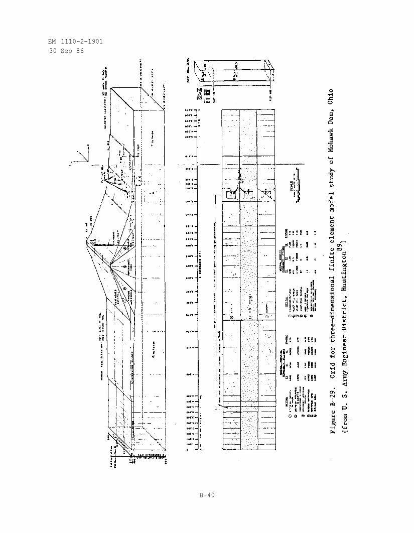
EM 1110-2-190130 Sep 86
B-40
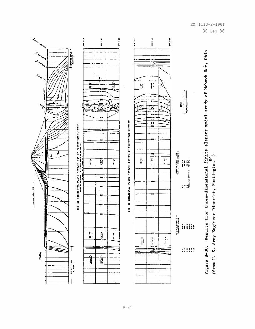
EM 1110-2-1901
30 Sep 86
B-41
EM 1110-2-1901
30 Sep 86
APPENDIX CANALYSIS OF PRESSURE INJECTION TESTS (Ziegler 1976)
C-1. Water Pressure Tests
a. Water pressure tests are conducted by pumping water into a boreholeat a constant pressure and measuring the flow rate. Water enters the rock massalong the entire length of borehole or along a test section (i.e., boreholeinterval) sealed off by one or more packers as shown in figure C-1. The testis rapid and simple to conduct and by conducting tests within intervals alongthe entire length of borehole, a permeability profile can be obtained.
b. In most pressure tests the water injection pressure is limited to avalue which is not expected to produce an increase in the fracture width. Anincrease in the fracture width will cause erroneously high flow rates result-ing in higher permeabilities than actually exist. A common criterion is tolimit the water injection pressure to 1 psi/ft of borehole depth above thewater table and 0.57 psi/ft of borehole depth below the water table. Thiscriterion results in a maximum injection pressure less than the effective over-burden pressure if the overburden has a unit weight greater than 144 lb/ft3.
c. The coefficient of permeability, based upon laminar flow, is com-puted for a vertical test section with the following assumptions:
(1) Medium is homogeneous and isotropic.
(2) Laminar flow governed by Darcy's law.
(3) Radial flow from a cylindrical and vertical borehole test sectionlength, Radial flow implies that the equipotential surfaces formcylinders symmetrical about the axis of the borehole test section.
(4) No inertia effects.
(5) Boundary conditions (fig. C-2).
(a) At r = ro . H = Ho .
(b) At r=R , H=0.
Where
r = radial distance from the test section (L)
ro = radius of borehole (L)
H = excess pressure head (L)
Ho = excess pressure head at the center of the test section (L) (eithermeasured within the test section, or computed allowing for fric-tional head losses within the drill pipe)
C-l
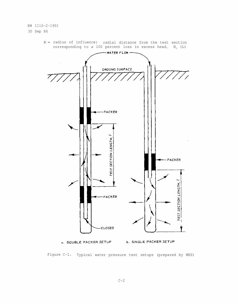
EM 1110-2-1901
30 Sep 86
R = radius of influence: radial distance from the test sectioncorresponding to a 100 percent loss in excess head, Ho (L)
Figure C-1. Typical water pressure test setups (prepared by WES)
C-2
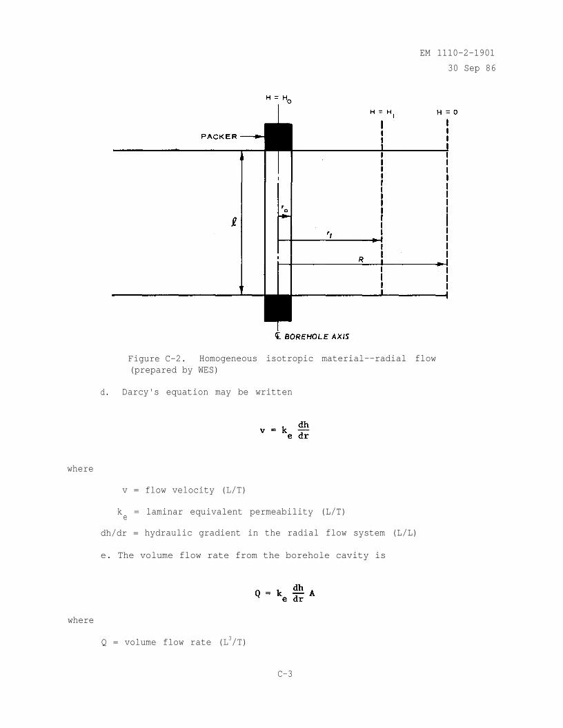
EM 1110-2-1901
30 Sep 86
Figure C-2. Homogeneous isotropic material--radial flow(prepared by WES)
d. Darcy's equation may be written
where
v = flow velocity (L/T)
ke
= laminar equivalent permeability (L/T)
dh/dr = hydraulic gradient in the radial flow system (L/L)
e. The volume flow rate from the borehole cavity is
where
Q = volume flow rate (L3/T)
C-3

EM 1110-2-1901
30 Sep 86
A = area of an equipotential surface (L2)
The area A in the radial system is
Thus
which can be written
and integrated
(C-1)
The negative sign can be dropped by choosing flow away from the borehole aspositive, thus
and the permeability is
C-4
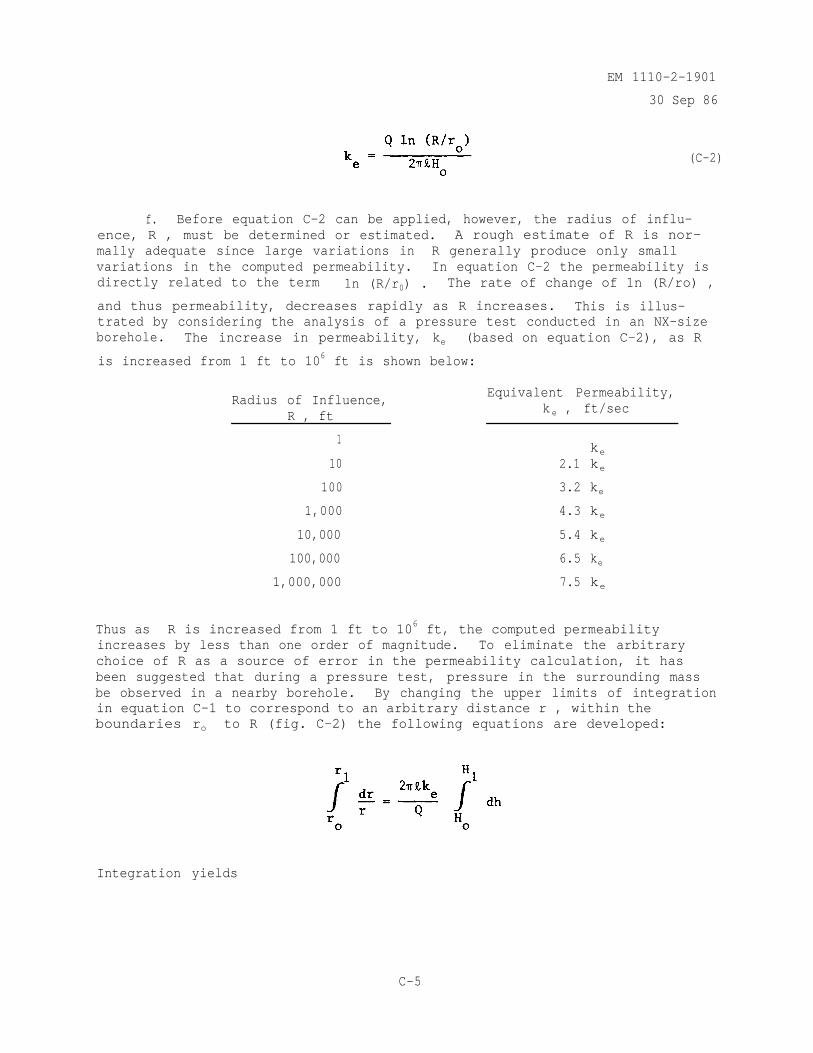
EM 1110-2-1901
30 Sep 86
(C-2)
f. Before equation C-2 can be applied, however, the radius of influ-ence, R , must be determined or estimated. A rough estimate of R is nor-mally adequate since large variations in R generally produce only smallvariations in the computed permeability. In equation C-2 the permeability isdirectly related to the term 1n (R/r0) . The rate of change of 1n (R/ro) ,
and thus permeability, decreases rapidly as R increases. This is illus-trated by considering the analysis of a pressure test conducted in an NX-sizeborehole. The increase in permeability, ke (based on equation C-2), as R
is increased from 1 ft to 106 ft is shown below:
Radius of Influence,R , ft
1
10
100
1,000
10,000
100,000
1,000,000
Equivalent Permeability,k e , ft/sec
ke
2.1 ke
3.2 ke
4.3 ke
5.4 ke
6.5 ke
7.5 ke
Thus as R is increased from 1 ft to 106 ft, the computed permeabilityincreases by less than one order of magnitude. To eliminate the arbitrarychoice of R as a source of error in the permeability calculation, it hasbeen suggested that during a pressure test, pressure in the surrounding massbe observed in a nearby borehole. By changing the upper limits of integrationin equation C-1 to correspond to an arbitrary distance r , within theboundaries ro to R (fig. C-2) the following equations are developed:
Integration yields
C-5
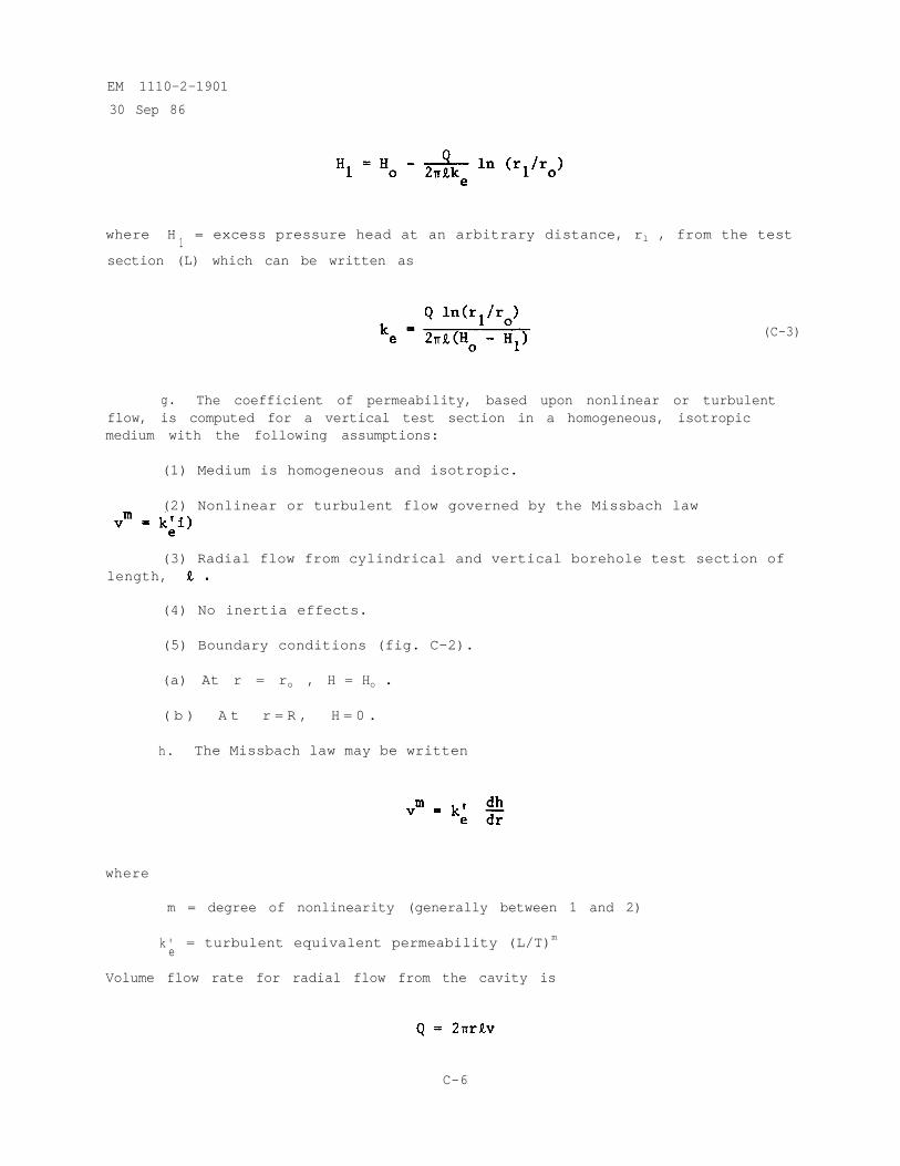
EM 1110-2-1901
30 Sep 86
where H1= excess pressure head at an arbitrary distance, rl , from the test
section (L) which can be written as
(C-3)
g. The coefficient of permeability, based upon nonlinear or turbulentflow, is computed for a vertical test section in a homogeneous, isotropicmedium with the following assumptions:
(1) Medium is homogeneous and isotropic.
(2) Nonlinear or turbulent flow governed by the Missbach law
(3) Radial flow from cylindrical and vertical borehole test section oflength,
(4) No inertia effects.
(5) Boundary conditions (fig. C-2).
(a) At r = ro , H = Ho .
( b ) A t r = R , H = 0 .
h. The Missbach law may be written
where
m = degree of nonlinearity (generally between 1 and 2)
k'e
= turbulent equivalent permeability (L/T)m
Volume flow rate for radial flow from the cavity is
C-6
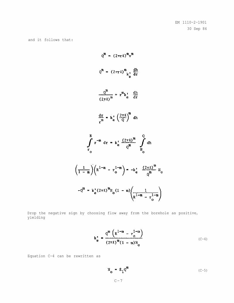
EM 1110-2-1901
30 Sep 86
and it follows that:
Drop the negative sign by choosing flow away from the borehole as positive,yielding
Equation C-4 can be rewritten as
(C-4)
(C-5)
C-7
EM 1110-2-1901
30 Sep 86
where
The logarithms of terms in equation C-5 yield the equation of a straight line:
log Ho = log E1 + m log Q
A plot of log Ho versus log Q will be a straight line with an arithmetic
slope equal to the degree of nonlinearity m .
i. The coefficient of permeability for laminar flow in fissures iscomputed for a vertical test section with the following assumptions:
(1) Vertical borehole test section of length is intersected by anarbitrary number of horizontal fissures.
(2) Fissures are constant aperture openings between smooth parallelplates.
(3) Radial flow occurs within each fissure and is governed by Darcy'slaw. No flow occurs in material between fissures.
(4) Each fissure has the same equivalent parallel plate aperture, e .
(5) No inertia effects.
(6) Boundary conditions (fig. C-3).
(a) At r = ro , H=Ho .
(b) At r = R , H=0.
j. The derivation of equations C-6 and C-7 proceeds in the same fashionas that given above for laminar flow through a homogeneous isotropic medium(equations C-2 and C-3). For the fissured medium the test section length,
is replaced by the quantity (ne) where n is the number of fissuresintersecting the test section and e is the equivalent parallel plateaperture of each fissure. The resulting expression for the flow rate Q is
C-8
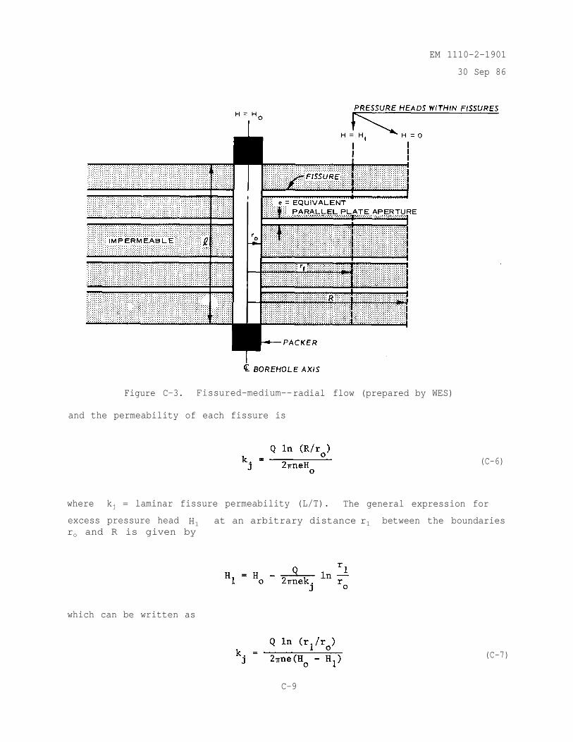
EM 1110-2-1901
30 Sep 86
Figure C-3. Fissured-medium--radial flow (prepared by WES)
and the permeability of each fissure is
(C-6)
where kj = laminar fissure permeability (L/T). The general expression for
excess pressure head H1 at an arbitrary distance r1 between the boundariesro and R is given by
which can be written as
(C-7)
C-9
EM 1110-2-1901
30 Sep 86
From the theory of viscous flow between smooth parallel plates
(C-8)
where
Equation C-8 is substituted into equation C-6 to solve for the equivalentparallel plate aperture, e :
k. The coefficient of permeability for nonlinear or turbulent flow infissures is computed for a vertical test section with the followingassumptions:
(1) Vertical borehole test section of length intersected by anarbitrary number of horizontal fissures.
(2) Fissures are constant aperture openings between smooth parallelplates.
(3) Radial flow occurs within each fissure and is governed by the
Missbach law (vm = k'i).j
No flows occur in material between fissures.
(4) Each fissure has the same equivalent parallel plate aperture, e .
(5) No inertial effects.
(6) Boundary conditions (fig. C-3).
(a) At r = ro , H = Ho .
(b) At r=R, H=0.
1. The derivation of equation C-9 proceeds in the same fashion as thatgiven above for nonlinear flow through a homogeneous isotropic medium (equa-tion C-4). For the fissured medium, the test section length, , is replaced
C-10
EM 1110-2-1901
30 Sep 86
by the quantity ne where n is the number of fissures intersecting the testsection and e is the equivalent parallel plate aperture of each fissure.The resulting equation for the turbulent fissure permeability is
(C-9)
where k'j
= turbulent fissure permeability (L/T)m . Equation C-9 can be
rewritten as
where
(C-10)
The logarithms of terms in equation C-10 yielded the equation of a straightline:
A plot of log Ho versus log Q will be a straight line with an arithmetic
slope equal to the degree of nonlinearity, m .
C-2. Air Pressure Tests.
a. Air pressure tests are conducted similarly to water pressure tests,with the essential difference being the replacement of water with air. Theuse of air, however, requires that permeability equations be modified forapplication to a compressible fluid and a conversion must be made from air towater permeability. To compute the permeability, flow is assumed to belaminar and governed by Darcy's law. The material tested is assumed to be ahomogeneous isotropic porous medium. Darcy's law can be written
v = ki
C-11
EM 1110-2-1901
30 Sep 86
where
v = flow velocity (L/T)
k = coefficient of permeability (L/T)
i = hydraulic gradient (L/L)
b. The coefficient of permeability, k , is dependent on properties ofthe medium and fluid or gas. Since the test involves the flow of air andpermeability relating to the flow of water is desired, it is convenient tosolve for the intrinsic permeability, k , which is characteristic of themedium alone. The coefficient of permeability and intrinsic permeability areinterrelated (Davis and Dewiest 1966, and Muskat 1946). For the flow of water
(C-11)
where
ke
= laminar equivalent permeability (L/T)
= unit weight of water (F/L3)
= dynamic viscosity of water
c. The conversion of intrinsic permeability measured by an air test tothe water permeability can be in error due to differences in gas and fluidflow phenomena i.e., the Klinkenberg Effect (Weeks 1978), or alteration of thematerial's physical properties caused by a chemical reaction with the fluid orgas (Davis and Dewiest 1966, and Lynch 1962). In sediments rich in clayminerals, water permeability calculated from air measurements may be overesti-mated by a factor of 100 (Davis and Dewiest 1966). This overestimation iscaused by a hydration of clays during waterflow which does not occur duringairflow. Test results should be applied with caution as more experience andstudies are needed to determine the limitations of equation C-11.
d. Muskat (1946, p. 679) observed that the flow of incompressibleliquids is easily modified for application to the flow of a compressible gas.Steady-state solutions for analyzing constant water pressure test results aregenerally written in the form
C-12
EM 1110-2-1901
30 Sep 86
where
Q = volume flow rate (L3/T)
= length of test section (L)
Ho = excess pressure head at the center of the test section (L)
The term [C] is dependent on assumed flow and boundary conditions. The follow-ing equation is commonly used in analyzing water pressure test results.
where
R = radius of influence (L)
ro = radius of borehole (L)
After solving for Q and converting to intrinsic permeability, k ,equation C-12 becomes
(C-12)
(C-13)
where Po = excess pressure at the center of test section (F/L2) the
equation (C-13) is based-on the assumption that:
(1) The medium is a homogeneous and isotropic porous continuum.
(2) The flow emitting from a cylindrical section of borehole islaminar, and governed by Darcy's equation.
(3) The flow pattern is ellipsoidal and symmetrical about the axis ofthe borehole test section.
e. Equation C-13 can be modified for analyzing air pressure testresults by making similar assumptions and considering the fluid to becompressible. Before modification, equation C-13 must be written in terms ofabsolute pressures. The pressure, Po , equals the absolute pressure in thetest section, minus atmospheric pressure, Equation C-13 becomes
C-13
EM 1110-2-1901
30 Sep 86
(C-14)
f. Equation C-14 is modified to apply to the flow of gas by replacing
the pressure term by the expression
where
where
is a constant at any point in the flow and defined as
(C-15)
(C-16)
= mass density (F-T2/L)/L3
g = acceleration due to gravity (L/T2)
= absolute pressure (F/L2)
= unit weight of gas (F/L3)
and the exponent, M , determines the thermodynamic nature of the expansion ofa gas as it moves from high- to low-pressure regions. The resulting equation(equation C-18 below) is in terms of weight flow rate rather than volume flowrate. Since gases are highly compressible, the volume flow rate will varywith pressure and temperature along the flow path. However, the weight flowrate can be assumed to remain constant. Weight flow rate,flow rate, Q , at any point in the flow are related by
QWF , and volume
(C-17)
Substitution of expression C-15 into equation C-14 (replace µw with µa)
yields the following expression for the weight flow rate of air:
C-14
EM 1110-2-1901
30 Sep 86
(C-18)
where
Q W F = weight flow rate (F/T)
µa = dynamic viscosity of air (F T/L2)
g. For convenience, the value of M is assumed equal to 1 which cor-responds to isothermal expansion of an ideal gas as it moves from the boreholethrough the medium (for adiabatic expansion, M < 1). Since equation C-16 is
valid at any point in the flow and M + 1 , can be replaced by
where and are the unit weight of air and absolute pressure in the
test section, respectively. By substituting M = 1 and in
equation C-18, the intrinsic permeability, k , can be expressed as
(C-19)
h. Parameters used in equation C-19 are measured or computed from thetest data. The test section length, , and radius of test section, ro ,
are determined from the test setup.
equals 14.7 psi or 2,120 lbF/ft2.
Standard atmospheric pressure,
The absolute pressure in the test section,
is equal to the gage pressure measured in the test section, PO , plus
atmospheric pressure, The dynamic viscosity of air, µa , depends only
on the temperature, and its variation is small over a large range of tempera-
For example, air viscosity increases from approximately 0.035 x 10⁻⁵
tures.
to 0.045 x 10⁻⁵
lbF-sec/ft2 as temperature increases from 0 to 250° F. In
general, the dynamic viscosity of air can be assumed to equal 0.38 x
10-5 lbF-sec/ft2 which is the viscosity of air at 68° F.
i. The weight flow rate from the test section, QWF , is constant along
the flow path and can be determined at the manifold by applying equation C-17:
C-15
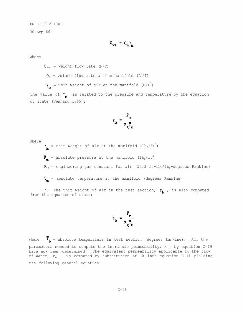
EM 1110-2-1901
30 Sep 86
where
Q W F = weight flow rate (F/T)
Qm = volume flow rate at the manifold (L3/T)
= unit weight of air at the manifold (F/L3)
The value of is related to the pressure and temperature by the equation
of state (Vennard 1965):
where= unit weight of air at the manifold (lbF/ft
3)
absolute pressure at the manifold (lbF/ft2)
R g = engineering gas constant for air (53.3 ft-lbF/lbF-degrees Rankine)
= absolute temperature at the manifold (degrees Rankine)
j. The unit weight of air in the test section, , is also computedfrom the equation of state:
where = absolute temperature in test section (degrees Rankine). All the
parameters needed to compute the intrinsic permeability, k , by equation C-19have now been determined. The equivalent permeability applicable to the flowof water, ke , is computed by substitution of k into equation C-11 yielding
the following general equation:
C-16
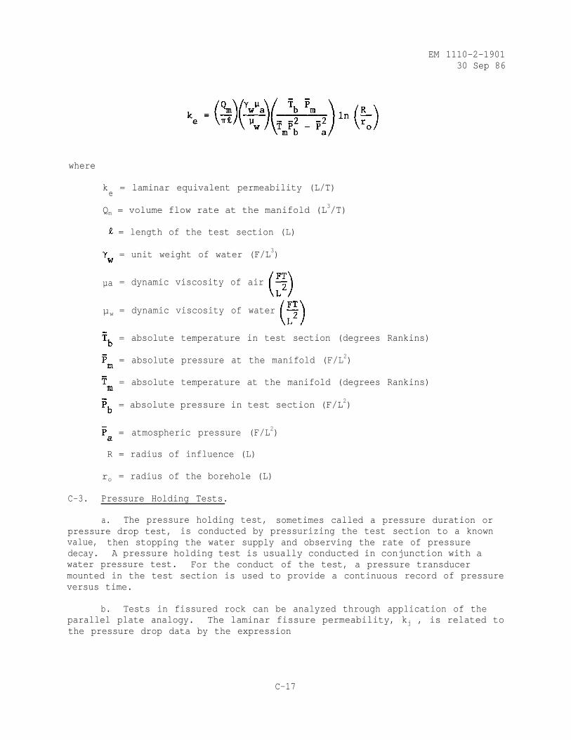
EM 1110-2-190130 Sep 86
where
ke
= laminar equivalent permeability (L/T)
Qm = volume flow rate at the manifold (L3/T)
= length of the test section (L)
= unit weight of water (F/L3)
µa = dynamic viscosity of air
µw = dynamic viscosity of water
= absolute temperature in test section (degrees Rankins)
= absolute pressure at the manifold (F/L2)
= absolute temperature at the manifold (degrees Rankins)
= absolute pressure in test section (F/L2)
= atmospheric pressure (F/L2)
R = radius of influence (L)
ro = radius of the borehole (L)
C-3. Pressure Holding Tests.
a. The pressure holding test, sometimes called a pressure duration orpressure drop test, is conducted by pressurizing the test section to a knownvalue, then stopping the water supply and observing the rate of pressuredecay. A pressure holding test is usually conducted in conjunction with awater pressure test. For the conduct of the test, a pressure transducermounted in the test section is used to provide a continuous record of pressureversus time.
b. Tests in fissured rock can be analyzed through application of theparallel plate analogy. The laminar fissure permeability, kj , is related tothe pressure drop data by the expression
C-17
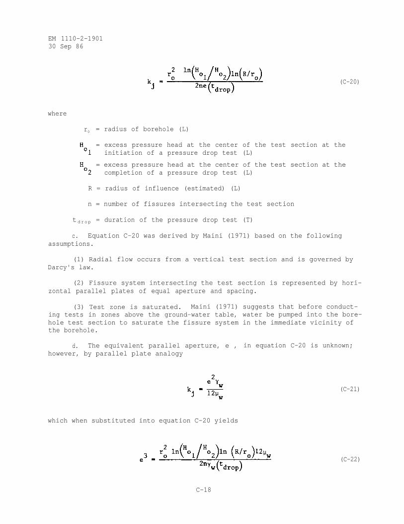
EM 1110-2-190130 Sep 86
(C-20)
where
ro = radius of borehole (L)
= excess pressure head at the center of the test section at theinitiation of a pressure drop test (L)
= excess pressure head at the center of the test section at thecompletion of a pressure drop test (L)
R = radius of influence (estimated) (L)
n = number of fissures intersecting the test section
tdrop = duration of the pressure drop test (T)
c. Equation C-20 was derived by Maini (1971) based on the followingassumptions.
(1) Radial flow occurs from a vertical test section and is governed byDarcy's law.
(2) Fissure system intersecting the test section is represented by hori-zontal parallel plates of equal aperture and spacing.
(3) Test zone is saturated. Maini (1971) suggests that before conduct-ing tests in zones above the ground-water table, water be pumped into the bore-hole test section to saturate the fissure system in the immediate vicinity ofthe borehole.
d. The equivalent parallel aperture, e , in equation C-20 is unknown;however, by parallel plate analogy
which when substituted into equation C-20 yields
(C-21)
(C-22)
C-18
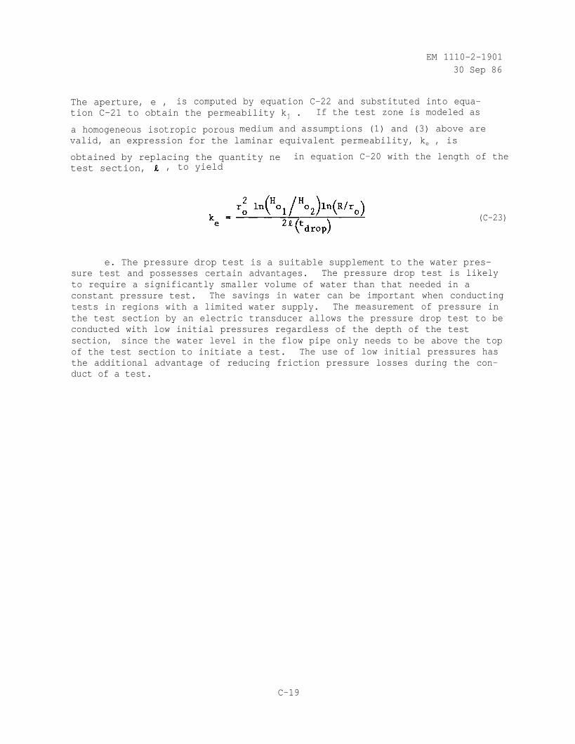
EM 1110-2-190130 Sep 86
The aperture, e , is computed by equation C-22 and substituted into equa-tion C-21 to obtain the permeability kj . If the test zone is modeled as
a homogeneous isotropic porous medium and assumptions (1) and (3) above arevalid, an expression for the laminar equivalent permeability, ke , is
obtained by replacing the quantity ne in equation C-20 with the length of thetest section, , to yield
(C-23)
e. The pressure drop test is a suitable supplement to the water pres-sure test and possesses certain advantages. The pressure drop test is likelyto require a significantly smaller volume of water than that needed in aconstant pressure test. The savings in water can be important when conductingtests in regions with a limited water supply. The measurement of pressure inthe test section by an electric transducer allows the pressure drop test to beconducted with low initial pressures regardless of the depth of the testsection, since the water level in the flow pipe only needs to be above the topof the test section to initiate a test. The use of low initial pressures hasthe additional advantage of reducing friction pressure losses during the con-duct of a test.
C-19
EM 1110-2-1901 30 Apr 93 Change 1
APPENDIX D FILTER DESIGN
D-l. General. The objective of filters and drains used as seepage control measures for embankments is to efficiently control the movement of water within and about the embankment. In order to meet this objective, filters and drains must, for the project life and with minimum maintenance, retain the protected materials, allow relatively free movement of water, and have suffi- cient discharge capacity~. Eor~~design,.these.~three~necessiries. are termed, respectively, piping or stability requirement, permeability requirement, and discharge capacity. This appendix will explain how these requirements are met for cohesionless and cohesive materials, and provide general construction guidance for installation of filters and drains. The terms filters and drains are sometimes used interchangeably. Some definitions classify filters and drains by function. In this case, filters must retain the protected soil and have a permeability greater than the protected soil but do not need to have a particular flow or drainage capacity since flow will be perpendicular to the interface between the protected soil and filter. Drains, however. while meet- ing the requirements of filters, must have an adequate discharge capacity since drains collect seepage and conduct it to a discharge point or area. In practice, the critical element is not definition, but recognition, by the designer, when a drain must collect and conduct water. In this case the drain must be properly designed for the expected flows. Where it is not possible to meet the criteria of this appendix, the design must be cautiously done and based on carefully controlled laboratory filter tests (Perry 1985).
D-2. Stability. Filters and drains(l) allow seepage to move cut of a pro- tected soil more quickly than the seepage moves within the protected soil. Thus, the filter material must be more open and have a larger grain size than the protected soil. Seepage from the finer soil to the filter can cause move- ment of the finer soil particles from the protected soil into and through the filter. This movement will endanger the embankment.(2) Destruction of the protected soil structure may occur due to the loss of material. Also, clog- ging of the filter may occur causing loss of the filter's ability to remove
(1) In paragraphs D-2 and D-3 the criteria apply to drains and filters; for brevity, only the word filter will be used.
(2) In practice, it is normal for a small amount of protected soil to move into the filter upon initiation of seepage. This action should quickly stop and may not be observed when seepage first occurs. This is one
reason that initial operation of embankment seepage control measures
should be closely observed by qualified personnel.
D-l
EM 1110-2-1901 30 Apr 93 Change 1
water from the protected soil. Criteria developed by many years of experience are used to design filters and drains which will prevent the movement of pro- tected soil into the filter. This criterion, called piping or stability cri- terion, is based on the grain-size relationship between the protected soil and the filter. In the following. the small character "d" is used to represent the grain size for the protected (or base) material and the large character "D" the grain size for the filter material.
Determine filter gradation limits using the following steps:'3'
1. Determine the gradation curve (grain-size distribution) of the base soil material. Use enough samples to define the range of grain sizes for the base soil or soils and design the filter gradation based on the base soil that requires the smallest D,, size.
2. Proceed to step 4 if the base soil contains no gravel (material larger than No. 4 sieve).
3. Prepare adjusted gradation curves for base soils with particles larger
than the No. 4 (4.75 mm) sieve.
a. Obtain a correction factor by dividing 100 by the percent passing the No. 4 (4.75 mm) sieve.
b. Multiply the percentage passing each sieve size of the base soil smaller than No. 4 (4.75 mm) by the correction factor from step 3a.
c. Plot these adjusted percentages to obtain a new gradation curve
d. Use the adjusted curve to determine the percent passing the No. 200 (0.075 mm) sieve in step 4.
4. Place the base soil in a category based on the percent passing the No. 200 (0.075 mm) sieve in accordance with Table D-l.
5. Determine the maximum D,, size for the filter in accordance with Table D-2. Note that the maximum D,, is not required to be smaller than 0.20 mm.
6. To en.sure sufficient permeability, set the minimum D,, greater than or equal to 3 to 5 x maximum d,, of the base soil before regrading but no less than 0.1 mm.
(3) Guide for Determining the Gradation of Sand and Gravel Filters, Soil Mechanics Note No. 1, U.S. Department of Agriculture Soil Conservation Services, Engineering Division, Jan 1986.
D-2
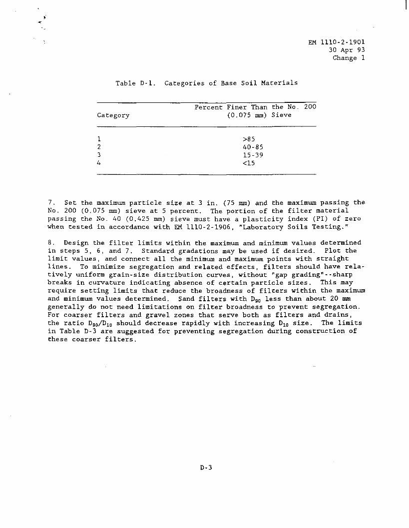
EM 1110-2-1901 30 Apr 93 Change 1
Table D-l. Categories of Base Soil Materials
Category Percent Finer Than the No. 200
(0.075 mm) Sieve
1 X35 2 40-85 3 15-39 4 <15
7. Set the maximum particle size at 3 in. (75 mm) and the maximum passing the No. 200 (0.075 mm) sieve at 5 percent. The portion of the filter material passing the No. 40 (0.425 mm) sieve must have a plasticity index (PI) of zero when tested in accordance with F.M 1110-2-1906, "Laboratory Soils Testing."
8. Design the filter limits within the maximum and minimum values determined in steps 5, 6, and 7. Standard gradations may be used if desired. Plot the limit values, and connect all the minimum and maximum points with straight lines. To minimize segregation and related effects, filters should have rela- tively uniform grain-size distribution curves, without "gap grading"--sharp breaks in curvature indicating absence of certain particle sizes. This may require setting limits that reduce the broadness of filters within the maximum and minimum values determined. Sand filters with D,, less than about 20 mm generally do not need limitations on filter broadness to prevent segregation. For coarser filters and gravel zones that .serve both as filters and drains, the ratio D&D,, should decrease rapidly with increasing D,, size. The limits in Table D-3 are suggested for preventing segregation during construction of these coarser filters.
D-3
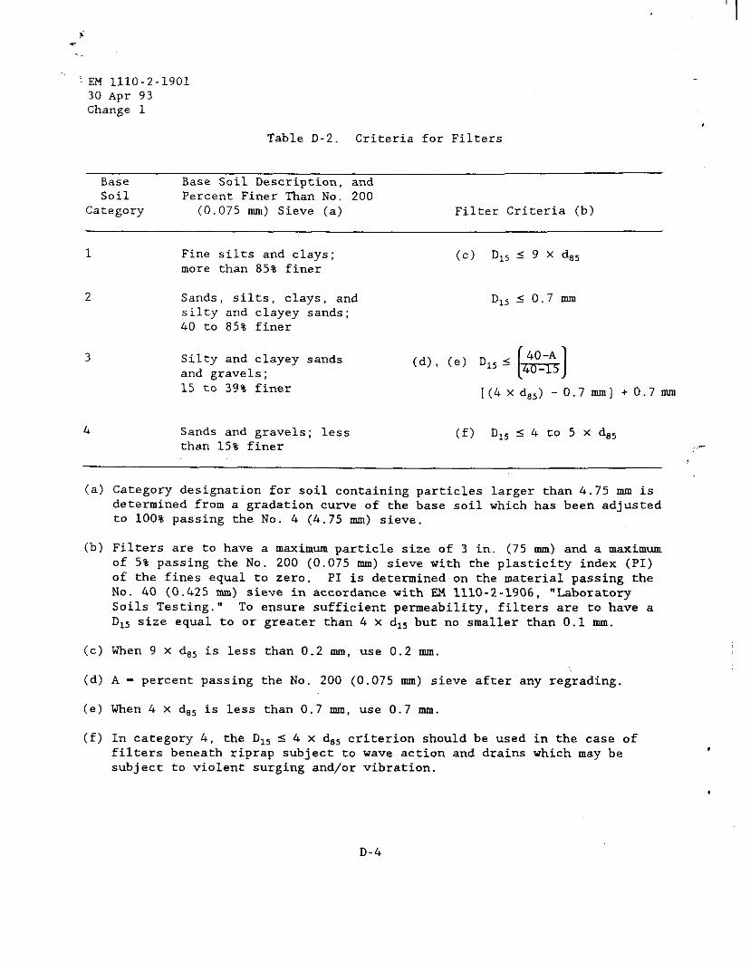
’ I
1 EM 1110-2-1901 30 Apr 93 Change 1
Table D-2. Criteria for Filters
Base Base Soil Description, and Soil Percent Finer Than No. 200
Category (0.075 mm) Sieve (a) Filter Criteria (b)
1 Fine silts and clays; Cc) D,, s 9 X 4, more than 85% finer
2 Sands, silts, clays, and D,, 5 0.7 mm silty and clayey sands; 40 to 85% finer
3 Silty and clayey sands Cd), (=I D,, 5 and gravels; 15 to 39% finer [(4x d,,) - 0.7 mm] + 0.7 mm
4 Sands and gravels; less (f) D,,s4to5xd,, than 15% finer .-
(a) Category designation for soil containing particles larger than 4.75 mm is determined from a gradation curve of the base soil which has been adjusted to 100% passing the No. 4 (4.75 mm) sieve.
(b) Filters are to have a maximum particle size of 3 in. (75 mm) and a maximum of 5% passing the No. 200 (0.075 mm) sieve with the plasticity index (PI) of the fines equal to zero. PI is determined on the material passing the No. 40 (0.425 mm) sieve in accordance with EM 1110-2-1906, "Laboratory Soils Testing." To ensure sufficient permeability, filters are to have a D,, size equal to or greater than 4 x d,, but no smaller than 0.1 mm.
(c) When 9 x d,, is less than 0.2 mm, use 0.2 mm.
Cd) A - percent passing the No. 200 (0.075 mm) sieve after any regrading.
(e) When 4 x d,, is less than 0.7 mm, use 0.7 mm.
(f) In category 4, the D,, 5 4 x d,, criterion should be used in the case of filters beneath riprap subject to wave action and drains which may be subject to violent surging and/or vibration.
D-4
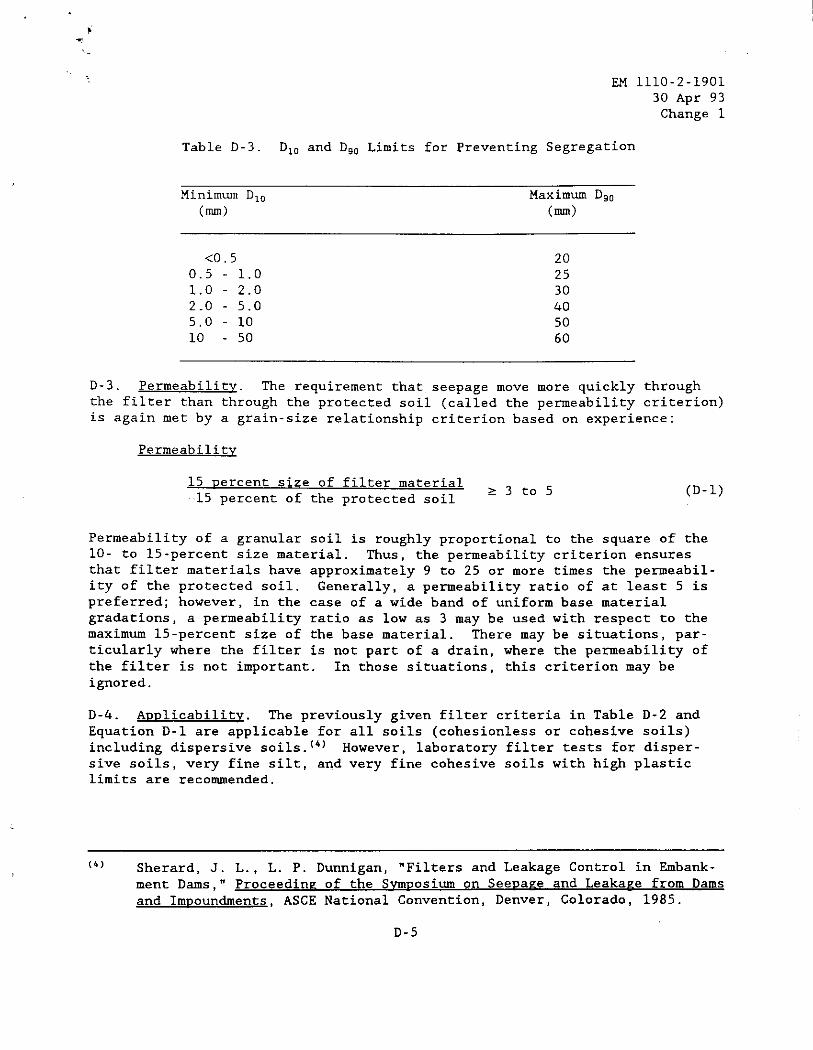
EM 1110-2-1901 30 Apr 93 Change 1
Table D-3. D,, and D,, Limits for Preventing Segregation
Minimum D,, Maximum D,,
(mm) (mm)
<0.5 20 0.5 - 1.0 25 1.0 2.0 30 2.0 - 5.0 40 5.0 10 50 10 - 50 60
D-3. Permeability. The requirement that,seepage move more quickly through the filter than through the protected soil (called the permeability criterion) is again met by a grain-size relationship criterion based on experience:
Permeability
15 percent size of filter material .I5 percent of the protected soil
>3to5 (D-1)
Permeability of a granular soil is roughly proportional to the square of the lo- to 15-percent size material. Thus, the permeability criterion ensures that filter materials have approximately 9 to 25 or more times the permeabil- ity of the protected soil. Generally, a permeability ratio of at least 5 is preferred; however, in the case of a wide band of uniform base material gradations, a permeability ratio as low as 3 may be used with respect to the maximum 15-percent size of the base material. There may be situations, par- ticularly where the filter is not part of a drain, where the permeability of the filter is not important. In those situations, this criterion may be ignored.
D-4. AuDlicabilitu. The previously given filter criteria in Table D-2 and Equation D-l are applicable for all soils (cohesionless or cohesive soils) including dispersive soils."' However, laboratory filter tests for disper- sive soils, very fine silt, and very fine cohesive soils with high plastic limits are recommended.
(4) Sherard, J. L., L. P. Dunnigan, "Filters and Leakage Control in Embank-
ment Dams," Proceedine of the Svmuosium on SeeDaze and LeakaPe from Dams and Impoundments, ASCE National Convention, Denver, Colorado, 1985.
D-5
' EM 1110-2-1901 30 Apr 93 Change 1
D-5. Perforated Piwe."' The following criteria are applicable for prevent- ing infiltration of filter material into perforated pipe, screens, etc.:
Minimum 50 Dercent size of filter material hole diameter or slot width
2 1.0 (D-2)
In many instances a filter material meeting the criteria given by Table D-2 and Equation D-l relative to the material~being drained is too fine to meet the criteria given by Equation D-2. In these instances, multilayered or "graded" filters are required. In a graded filter each layer meets the requirements given by Table D-2 and Equation D-l with respect to the pervious layer with the final layer in which a collector pipe is bedded also meeting the requirements given by Equation D-2. Graded filter systems may also be needed when transitioning from fine to coarse materials in a zoned embankment or where coarse material is required for improving the water-carrying capacity of the system.
D-6. Gau-Graded Base. The preceding criteria cannot, in most instances, be applied directly to protect severely gap- or skip-graded soils. In a gap- graded soil such as that shown in Figure D-l, the coarse material simply floats in the matrix of fines. Consequently, the scattered coarse particles will not defer the migration of fines as they do in a well-graded material. For such gap-graded soils, the filter should be designed to protect the fine a. '-
matrix rather than the total range of particle sizes. This is illustrated in Figure D-l. The 85-percent size of the total sample is 5.2 mm. Considering only the matrix material, the 85-percent size would be 0.1 mm resulting in a much finer filter material being required. This procedure may also be fol- lowed in some instances where the material being drained has a very wide range of particle sizes (e.g., materials graded from coarse gravels to significant percentages of silt or clay). For major structures such a design should be checked with filter tests.
D-7. GaD-Graded Filter. A gap-graded filter material must never be specified or allowed since it will consist of either the coarse particles floating in the finer material or the fine material having no stability within the voids produced by the coarse material. In the former case the material may not be permeable enough to provide adequate drainage. The latter case is particu- larly dangerous since piping of the protected material can easily occur through the relatively large, loosely filled voids provided by the coarse material.
(5) FM 1110-2-2300 states, "Collector pipe should not be placed within the
embankment, except at the downstream toe, because of the danger of either breakage or separation of joints, resulting from fill placement and compaction operations, or settlement, which might result in either
clogging and/or piping."
D-6
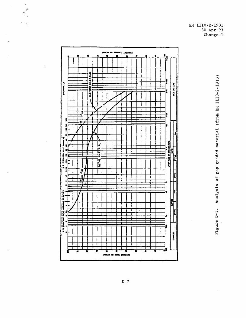
EM 1110-2-1901 30 Apr 93 Change 1
-a---
D-7
EM 1110-2-1901
30 Apr 93 ',... Change 1 ,
D-8. Broadlv Graded Base. One of the more common soils used for embankment
darns is a broadly graded material with particle sizes ranging from clay sizes to coarse gravels and including all intermediate sizes. These soils may be of
glacial, alluvial-colluvial, or weathered rock origin. As noted by Sherard, since the 85-percent size of the soil is commonly on the order of 20 to 30 mm, a direct application of the stability criteria D,,/d,, 5 4 to 5 would allow very coarse uniform gravel without sand sizes as a downstream filter, which would not be satisfactory (Sherard 1979). The typical broadly graded soils fall in Soil Category 2 in Table D-2 and require a sand or gravelly filter
with D,, 5 0.7 mm.
D-9. Example of Graded Filter Desipn for Drain. Seldom, if ever, is a single gradation curve repreSent=tiVe of a given material. A material is generally represented by a gradation band which encompasses all the individual gradation
curves. Likewise, the required gradation for the filter material is also given as a band. The design of a graded filter which shows the application of the filter criteria where the gradations are represented by bands is illus- trated in Figure D-2. A typical two-layer filter for protecting an impervious core of a dam is illustrated. The impervious core is a fat clay (CH) with a trace of sand which falls in Category 1 soil in Table D-2. The criterion D,, 5 9 x d,, is applied and a "point a" is established in Figure D-2. Filter material graded within a band such as that shown for Filter A in Figure D-2 is acceptable based on the stability criteria. The fine limit of the band was c'-
arbitrarily drawn, and in this example, is intended to represent the gradation of a readily available material. A check is then made to ensure that the 15-percent size of the fine limit of the filter material band (point b) is equal to or greater than 3 to 5 times the 15-percent size of the coarse limit of the drained material band (point c). Filter A has a minimum D,, size and a maximum D,, size such that, based on Table D-3, segregation during placement can be prevented. Filter A meets both the stability and permeability require- ments and is a suitable filter material for protecting the impervious core material. The second filter, Filter B. usually is needed to transition from a fine filter (Filter A) to coarse materials in a zoned embankment dam. Filter B must meet the criteria given by Table D-2 with respect to Filter A.
For stability. the 15-percent size of the coarse limit of the gradation band for the second filter (point d) cannot be greater than 4 to 5 times the 85-percent size of the fine limit of the gradation band for Fi1ter.A
(point e). For permeability, the 15-percent size of the fine limit (point f) must be at least 3 to 5 times greater than the 15-percent size of the coarse limit for Filter A (point a). With points d and f established, the fine and coarse limits for Filter B may be established by drawing curves through the points approximately parallel to the respective limits for Filter A. A check is then made to see that the ratio of maximum D,,/minimum D,, size of Filter B is approximately in the range as indicated in Table D-3. A well-graded filter which usually would not meet the requirements in Table D-3 may be used if
segregatzion can be controlled during placement. Figure D-2 is intended to show only the principles of filter design. The design of thickness of a
D-8
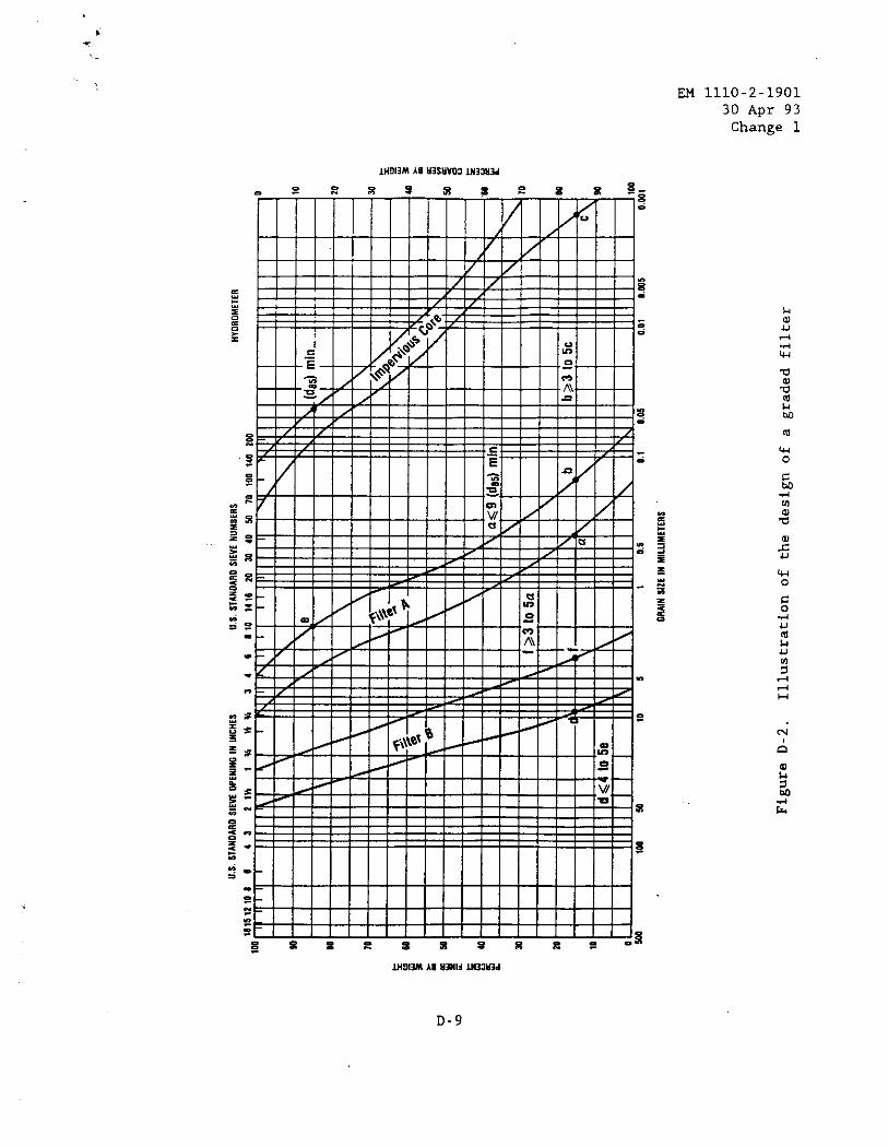
EM 1110-2-1901 30 Apr 93 Change 1
, I
EM 1110-2-1901 30 Apr 93 Change 1
filter for sufficient seepage discharge capacity is done by applying Darcy's
Law, Q - kia, and one example is presented in Chapter 8 of the main text.
D-10. ConstruCtiOn. FN 1110-2-1911 and EM 1110-Z-2300 provide guidance for
construction. Major concerns during construction include:
Prevention of contamination of drains and filters by runoff contain-
ing sekment, dust, construction traffic, and mixing with nearby fine-grained
materials during placement and compaction. Drain and filter material may be kept at an elevation higher than the surrounding fine-grained materials during construction to preventcontamination by sediment-carrying runoff.
b. Prevention of segregation, particularly well-graded filters, during
handling and placement.
c. Proper in-place density is usually required to be an average of 85-percent relative density with no area less than 80-percent relative
density. Granular materials containing little or no fines should be saturated during compaction to prevent "bulking" (low density) which can result in settlement when overburden materials are placed and the drain is subsequently
saturated by seepage flows.
d. Gradation should be monitored closely so that designed filter cri-
teria are met.
e. Thickness of layers should be monitored to ensure designed discharge
capacity and continuity of the filter.
Thus, quality control/assurance is very important during filter construction
because of the critical function of this relatively small part of the embankment.
D-11. Monitoriw. Monitoring of seepage quantity and quality (see Chapter 13 for method of monitoring seepage) once the filter is functioning is very important to the safety of the embankment. An increase in seepage flow may be due to a higher reservoir level,or may be caused by cracking or piping. The
source of the additional seepage should be determined and action taken as required (Chapters 12, 13, and 14). Decreases in seepage flows may also sig-
nal dangers such as clogging of the drain(s) with piped material, iron oxide, calcareous material, and effects of remedial grouting. Again, the cause should be determined and appropriate remedial measures taken. Drain outlets should be kept free of sediment and vegetation. In cold climates, design or maintenance measures should be taken to prevent clogging of drain outlets by
ice.
‘-k..
.
D-10