Distributed Generator Interconnection Relay User’s Guide · The SEL-547 Relay Manual describes...
294
Figure 0.1 SEL-547 Distributed Generator Interconnection Relay User’s Guide 20021206
Transcript of Distributed Generator Interconnection Relay User’s Guide · The SEL-547 Relay Manual describes...

Figure 0.1
SEL-547
Distributed GeneratorInterconnection Relay
User’s Guide
20021206

SEL-547 Relay Date Code 20021206
CAUTION: Equipment components are sensitive to electrostatic discharge (ESD). Undetectable permanent
damage can result if you do not use proper ESD procedures. Ground yourself, your work surface, and this equipment before removing any cover from this equipment. If your facility is not equipped to work with these components, contact SEL about returning this device and related SEL equipment for service.
!
DANGER: Disconnect or de-energize all external connections before opening this device. Contact with
hazardous voltages and currents inside this device can cause electrical shock resulting in injury or death.
!
DANGER: Contact with instrument terminals can cause electrical shock that can result in injury or death.!
WARNING: Have only qualified personnel service this equipment. If you are not qualified to service this
equipment, you can injure yourself or others, or cause equipment damage.
!
WARNING: Use of this equipment in a manner other than specified in this manual can impair operator safety
safeguards provided by this equipment.!
WARNING: This device is shipped with default passwords. Default passwords should be changed to
private passwords at installation. Failure to change each default password to a private password may allow unauthorized access. SEL shall not be responsible for any damage resulting from unauthorized access.
!
ATTENTION: Les composants de cet équipement sont sensibles aux décharges électrostatiques (DES). Des
dommages permanents non-décelables peuvent résulter de l’absence de précautions contre les DES. Raccordez-vous correctement à la terre, ainsi que la surface de travail et l’appareil avant d’en retirer un panneau. Si vous n’êtes pas équipés pour travailler avec ce type de composants, contacter SEL afin de retourner l’appareil pour un service en usine.
!
DANGER: Débrancher tous les raccordements externes avant d’ouvrir cet appareil. Tout contact avec des
tensions ou courants internes à l’appareil peut causer un choc électrique pouvant entraîner des blessures ou la mort.
!
DANGER: Tout contact avec les bornes de l’appareilpeut causer un choc électrique pouvant entraîner des
blessuers ou la mort.!
AVERTISSEMENT: Seules des personnes qualifiées peuvent travailler sur cet appareil. Si vous
n’êtes pas qualifiés pour ce travail, vous pourriez vous blesser avec d’autres personnes ou endommager l’équipement.
!
AVERTISSEMENT: L'utilisation de cet appareil suivant des procédures différentes de celles indiquées
dans ce manuel peut désarmer les dispositifs de protection d'opérateur normalement actifs sur cet équipement.
!
AVERTISSEMENT: Cet appareil est expédié avec des mots de passe par défaut. A l’installation, les mots de
passe par défaut devront être changés pour des mots de passe confidentiels. Dans le cas contraire, un accés non-autorisé á l’équipement peut être possible. SEL décline toute responsabilité pour tout dommage résultant de cet accés non-autorisé.
!
The software (firmware), schematic drawings, relay commands, and relay messages are copyright protected by the United States Copyright Law and International Treaty provisions. All rights are reserved.
You may not copy, alter, disassemble, or reverse-engineer the software. You may not provide the software to any third party.
All brand or product names appearing in this document are the trademark or registered trademark of their respective holders.
ACSELERATOR, Connectorized, CONSELTANT, Job Done, Schweitzer Engineering Laboratories, , SEL-PROFILE, and SELOGIC are registered trademarks of Schweitzer Engineering Laboratories, Inc.
The English language manual is the only approved SEL manual.
� 2002 Schweitzer Engineering Laboratories. All rights reserved.
This product is covered by U.S. Patent(s) Pending, and Foreign Patent(s) Issued and Pending.
This product is covered by the standard SEL 10-year warranty. For warranty details, visit www.selinc.com or contact your customer service representative. PM547-02

Date Code 20021206 SEL-547 Relay
Table of Contents
List of Tables ....................................................................................................................................................... iii
List of Figures .................................................................................................................................................... vii
Preface................................................................................................................................................................... xi
Section 1: Introduction and SpecificationsFeatures........................................................................................................................................................ U.1.2Applications................................................................................................................................................. U.1.5Specifications ............................................................................................................................................ U.1.16
Section 2: InstallationStep 1: Mounting the Relay Enclosure........................................................................................................ U.2.2Step 2: Connecting the Relay ...................................................................................................................... U.2.3
Section 3: Basic Relay OperationsStep 3: Powering the Unit............................................................................................................................ U.3.2Step 4: Establishing Communications......................................................................................................... U.3.3Step 5: Changing the Default Passwords..................................................................................................... U.3.5Step 6: Checking Relay Status .................................................................................................................... U.3.8Step 7: Setting the Date and Time ............................................................................................................... U.3.9Step 8: Understanding and Using EZ Settings .......................................................................................... U.3.10Step 9: Viewing Metering Quantities ........................................................................................................ U.3.25Step 10: Reading SER and Event Reports................................................................................................. U.3.27Step 11: Operating Relay Outputs............................................................................................................. U.3.28Step 12: Checking LEDs ........................................................................................................................... U.3.29
Section 4: Testing and TroubleshootingTesting ......................................................................................................................................................... U.4.2Troubleshooting........................................................................................................................................... U.4.7
Appendix A: Firmware and Manual VersionsFirmware..................................................................................................................................................... U.A.1Instruction Manual...................................................................................................................................... U.A.2
Appendix B: Firmware Upgrade InstructionsFirmware (Flash) Upgrade ..........................................................................................................................U.B.1
Appendix C: SEL-547 Relay EZ Settings SheetEZ Settings (use SHO E and SET E commands) ........................................................................................U.C.1Port Settings (use SHO P n and SET P n commands).................................................................................U.C.3

This page intentionally left blank

Date Code 20021206 SEL-547 Relay
List of TablesSection 1: Introduction and Specifications
Section 2: InstallationTable 2.1 Terminal Wiring Specifications.......................................................................................... U.2.4
Section 3: Basic Relay OperationsTable 3.1 SEL-547 Serial Port Settings.............................................................................................. U.3.4Table 3.2 Access Levels and Passwords ............................................................................................ U.3.5Table 3.3 Available ASCII Commands, by Access Level ................................................................. U.3.6Table 3.4 Actions at Settings Prompts ............................................................................................. U.3.10Table 3.5 EZ Settings for Protection and Control Elements in the SEL-547................................... U.3.11
Section 4: Testing and TroubleshootingTable 4.1 Testing Commands............................................................................................................. U.4.4Table 4.2 Low-Level Test Interface Scale Factors ............................................................................. U.4.4Table 4.3 Relay Self-Tests.................................................................................................................. U.4.6Table 4.4 Troubleshooting Procedures............................................................................................... U.4.7
Appendix A: Firmware and Manual VersionsTable A.1 Firmware Revision History ............................................................................................... U.A.1Table A.2 Instruction Manual Revision History ................................................................................ U.A.2
Appendix B: Firmware Upgrade Instructions
Appendix C: SEL-547 Relay EZ Settings Sheet

This page intentionally left blank

Date Code 20021206 SEL-547 Relay
List of FiguresSection 1: Introduction and Specifications
Figure 1.1 Typical SEL-547 Application (Transfer Switch Site Application). ................................... U.1.2Figure 1.2 Applications for the SEL-547. ........................................................................................... U.1.5Figure 1.3 Utility Normally Serves the Load. ..................................................................................... U.1.6Figure 1.4 SEL-547 Detects a Utility Source Problem........................................................................ U.1.7Figure 1.5 Load Is De-energized and Generator Starts Up.................................................................. U.1.7Figure 1.6 Generator Serves Load (or Partial Load) in Emergency Backup Role. ............................. U.1.8Figure 1.7 SEL-547 Detects Utility Source OK. ................................................................................. U.1.8Figure 1.8 All Load Restored and Temporary Parallel Exists. ............................................................ U.1.9Figure 1.9 Parallel Broken and Generator Turned Off. ....................................................................... U.1.9Figure 1.10 Utility and Customer Generator Normally Paralleled...................................................... U.1.10Figure 1.11 SEL-547 Detects Reverse Power Flow Into Utility. ......................................................... U.1.11Figure 1.12 Parallel Broken and Customer Load and Generator Isolated Together. ........................... U.1.12Figure 1.13 Individual Generator Paralleled With the Greater System. .............................................. U.1.13Figure 1.14 SEL-547 Detects Reverse Power Flow Into Generator. ................................................... U.1.13Figure 1.15 Parallel Broken and Motoring of Generator Stopped....................................................... U.1.14
Section 2: InstallationFigure 2.1 SEL-547 Chassis Dimensions (not to scale). ..................................................................... U.2.2Figure 2.2 SEL-547 Top and Front Views. .......................................................................................... U.2.3Figure 2.3 Alternative Close Supervision Wiring................................................................................ U.2.6Figure 2.4 Connection Details (Transfer Switch Site Application)..................................................... U.2.7Figure 2.5 Voltage and Current Connection Details (Individual Generator Site Application). .......... U.2.7
Section 3: Basic Relay OperationsFigure 3.1 Response Header. ............................................................................................................... U.3.4Figure 3.2 STA Command Response................................................................................................... U.3.8Figure 3.3 Settings RELID and TERMID. ........................................................................................ U.3.12Figure 3.4 Settings CRATIO, 3PCONN, and NOMV. ...................................................................... U.3.13Figure 3.5 Setting FREQ. .................................................................................................................. U.3.14Figure 3.6 Setting ROTATE............................................................................................................... U.3.15Figure 3.7 Setting LEDFL. ................................................................................................................ U.3.15Figure 3.8 Voltage Element Settings—Example 1. ........................................................................... U.3.16Figure 3.9 Voltage Element Settings—Example 2. ........................................................................... U.3.17Figure 3.10 Setting 27BLKP (Undervoltage Block). .......................................................................... U.3.18Figure 3.11 Frequency Element Settings—Example 1........................................................................ U.3.19Figure 3.12 Frequency Element Settings—Example 2........................................................................ U.3.19Figure 3.13 Frequency Element Setting Range Exclusions................................................................. U.3.20Figure 3.14 Directional Power Element Settings. ............................................................................... U.3.21Figure 3.15 Synchronism Check Element Settings. ............................................................................ U.3.23Figure 3.16 Full-Value (100%) Reverse-Phase-Sequence Voltage...................................................... U.3.24Figure 3.17 Reverse-Phase-Sequence Voltage Element. ..................................................................... U.3.24Figure 3.18 SER Command Display.................................................................................................... U.3.27Figure 3.19 Output Contact and Front-Panel LED Logic.................................................................... U.3.31
Section 4: Testing and Troubleshooting
Appendix A: Firmware and Manual Versions
Appendix B: Firmware Upgrade InstructionsFigure B.1 Establishing a Connection. .................................................................................................U.B.2Figure B.2 Selecting the Computer Serial Port. ...................................................................................U.B.3Figure B.3 Determining Communications Parameters for the Computer. ...........................................U.B.3Figure B.4 Setting Terminal Emulation. ..............................................................................................U.B.4

viii List of Figures
SEL-547 Relay Date Code 20021206
Figure B.5 Terminal Emulation Startup Prompt. ................................................................................. U.B.4Figure B.6 Correcting Port Setting. ..................................................................................................... U.B.5Figure B.7 Correcting Communications Parameters. .......................................................................... U.B.5Figure B.8 Commands Available in SELBOOT. ................................................................................... U.B.7Figure B.9 Matching Computer to Relay Parameters.......................................................................... U.B.8Figure B.10 Example Receive File Dialog Box..................................................................................... U.B.8Figure B.11 Example Filename Identifying Old Firmware Version...................................................... U.B.9Figure B.12 Downloading of Old Firmware.......................................................................................... U.B.9Figure B.13 Selecting the New Firmware to Send to the Relay. ......................................................... U.B.10Figure B.14 Transferring New Firmware to the Relay. ....................................................................... U.B.10
Appendix C: SEL-547 Relay EZ Settings Sheet

Date Code 20021206 User’s Guide SEL-547 Relay
PrefaceUUser’s Guide
This manual provides information and instructions for installing and operating the SEL-547 Relay. The two volumes that comprise this manual are for use by those experienced in protective relaying applications. Included are detailed technical descriptions of the relay and application examples.
Manual Overview
The SEL-547 Relay Manual consists of two volumes:
� User’s Guide
� Reference Manual
In addition, the SEL-547 Relay Manual contains a comprehensive index that encompasses both volumes of the manual. The index appears at the end of each printed volume.
The SEL-547 Relay Manual describes common aspects of relay application and use. Read the user’s guide to obtain the necessary information to install, set, test, and operate the relay; refer to the reference manual for more detailed information about settings and commands.
An overview of each manual section and topics follows.
User’s Guide Preface. Describes the manual organization and conventions used to present information.
Section 1: Introduction and Specifications. Introduces the SEL-547 Relay features; summarizes relay functions and applications; lists relay specifications, type tests, and ratings.
Section 2: Installation. Provides instructions and information for mounting and connecting the relay, including top and front views of the SEL-547, wiring connection and detail diagrams, and hardware installation instructions.
Section 3: Basic Relay Operations. Describes how to perform fundamental operations such as applying power and communicating with the relay, setting and viewing passwords, checking relay status, understanding and using EZ settings, viewing metering data, reading event reports and SER (Sequential Events Recorder) data, operating relay control outputs, checking LEDs, and using relay features to make commissioning easier.
Section 4: Testing and Troubleshooting. Describes techniques for testing, troubleshooting, and maintaining the SEL-547; it includes the list of status notification messages and a troubleshooting chart.
Appendix A: Firmware and Manual Versions. Lists the current firmware versions and details differences between the current and previous versions.
Appendix B: Firmware Upgrade Instructions. Provides instructions for upgrading firmware in the SEL-547.
Appendix C: SEL-547 Relay EZ Settings Sheet.

xii Preface
SEL-547 Relay User’s Guide Date Code 20021206
Reference Manual Preface. Describes the manual organization and conventions used to present information.
Section 1: Protection Functions. Describes the function of various relay protection elements, including voltage elements, synchronism check elements, frequency elements, and power elements. This section describes how the relay processes these elements and gives detailed specifics on protection scheme logic.
Section 2: SELOGIC Control Equation Programming. Describes the logic input/output of the relay, including SELOGIC® control equations, optoisolated inputs, remote control and latch control switches, setting groups, output contacts, and front-panel target LEDs.
Section 3: Analyzing Events. Explains how to obtain and interpret filtered event reports, event summaries, history reports, and SER reports.
Section 4: Communications. Explains the physical connection of the SEL-547 to various communications network topologies.
Section 5: SEL Communications Protocols. Describes the hardware and various SEL software protocols and how to apply these protocols; it includes details about SEL ASCII, SEL Compressed ASCII, SEL Distributed Port Switch, SEL Fast Meter, and SEL Fast Operate protocols.
Section 6: Modbus RTU Communications. Describes the Modbus® RTU Communications Protocol and how the SEL-547 supports this protocol.
Section 7: ASCII Commands. Provides information about serial port access levels, an ASCII command summary, and ASCII command explanations.
Section 8: Settings. Provides information about settings changes via the serial port, how EZ settings force global and Group 1 settings, and settings sheets.
Appendix A: Relay Word Bits. Contains a summary table of Relay Word bits.
SEL-547 Relay Command Summary. Contains a summary of relay commands.

xiiiPreface
Date Code 20021206 User’s Guide SEL-547 Relay
Page Numbering This manual shows page identifiers at the top of each page; see the figure below.
Page Number Format.
The page number appears at the outside edge of each page; a vertical bar separates the page number from the page title block. The two volumes of the SEL-547 Relay Manual are represented by the following building blocks:
� page number character string
� U is for User’s Guide
� R is for the Reference Manual.
� section number
� actual page number in the particular section
The section title is at the top of the page title block, with the main subsection reference in bold type underneath the section title.
ASCII Commands
Title Block Page Number
Serial Port Access LevelsR.7.3

xiv Preface
SEL-547 Relay User’s Guide Date Code 20021206
ConventionsTypographic Conventions
This user’s guide shows certain information with specific font and formatting attributes. The following table lists the typographic conventions in this documentation:
Typographic Conventions
Safety Information This manual uses three kinds of hazard statements, formatted as follows:
Indicates a potentially hazardous situation that, if not avoided, may result in minor or moderate injury or equipment damage.
! CAUTION
Indicates a potentially hazardous situation that, if not avoided, could result in death or serious injury.
! WARNING
Indicates an imminently hazardous situation that, if not avoided, will result in death or serious injury.
! DANGER
Example Description
STATUS ASCII and Compressed ASCII commands.
TAR 6 <Enter> Commands/input that you type.
{CLOSE} Relay front-panel pushbuttons.
<Enter> Single keystroke command.
<Ctrl+D> Multiple keystroke command to bring upa control window or activate a control function.
RELAY ELEMENTS Front-panel LCD menu items.
Start Dialog Boxes: Menu titles, options, drop-down or check box menu selections, highlighted options.

Date Code 20021206 User’s Guide SEL-547 Relay
Section 1U.User’s Guide
Introduction and Specifications
The SEL-547 Relay is a utility grade generation protection system relay designed to protect on-site 50–200 kW distributed generators with generated voltages up to 600 V.
The SEL-547 has the following inputs:
� Three phase-to-neutral voltage inputs
� One voltage input used for synchronization
� One phase current input
The SEL-547 has two communications ports:
� One EIA-485 port
This port serves as a connection to a Modbus® RTU communication protocol network.
� One EIA-232 port
This port provides an ASCII user interface and a method for loading firmware upgrades.
The SEL-547 is shipped with EZ settings—settings preset at the factory for basic applications. These settings are based on traditional relay applications and should be modified if you are using the SEL-547 for a custom application. Please refer to the SEL-547 Reference Manual for more details about settings and commands if you are developing a custom application.
This section introduces the SEL-547 and provides information on the following topics:
� Features
� Applications
� Specifications

U.1.2
SEL-547 Relay User’s Guide Date Code 20021206
Introduction and SpecificationsFeatures
Features
The SEL-547 has many protection, automation, and control features. Figure 1.1 depicts a typical SEL-547 application.
Figure 1.1 Typical SEL-547 Application (Transfer Switch Site Application).
Utility
Generator(s)
Load
3
1
VA, VB, VC
VA
Generator ControllerTransfer
Switch
Close
Close
Trip
OUT2
OUT3
59
81
47
27
32OUT1
OUT4
OUT5
1 IA
Close(+)
Close(+)
(+)
Trip
SpareClose
SpareTrip
25
VA, VB, VC, N IA
VS, NS
ENABLED
27
59
81
47
32
25
25VOLTAGEHOT
SEL-547 Relay LEDs
ANSIDev. No. Function
275981473225
UndervoltageOvervoltageOver- and underfrequencyReverse-phase-sequence voltageDirectional powerSynchronism check

U.1.3
Date Code 20021206 User’s Guide SEL-547 Relay
Introduction and SpecificationsFeatures
The SEL-547 features include the following:
Over- and Undervoltage Protection. The SEL-547 has two (2) overvoltage elements (ANSI device 59) and two (2) undervoltage elements (ANSI device 27) for tripping for abnormal system voltage conditions. Each element has an independently set timer.
Over- and Underfrequency Protection. The SEL-547 has four (4) frequency elements (individually configurable as over- or underfrequency elements; ANSI device 81) for tripping for abnormal system frequency conditions. Each element has an independently set timer.
Reverse-Phase-Sequence Voltage Alarming. Front-panel indication of reverse-phase-sequence voltage (ANSI device 47) indicates that the three-phase voltage inputs are wired incorrectly (or there is a wiring error somewhere in the system).
Directional Power Protection. The SEL-547 has one (1) directional power element (ANSI device 32) for tripping for such abnormal system conditions as reverse power and generator motoring. The directional power element derives its power operating quantity from single-phase voltage and current quantities. The element has an independent timer and can be set to detect forward or reverse power flow.
Synchronism Check Close Supervision. The SEL-547 has one (1) synchronism-check element (ANSI device 25) for system restoration supervision. Angle, voltage, and slip frequency settings provide for secure operation.
Front-Panel LEDs. Eight LEDs indicate relay and protection/control element status. The LEDs momentarily flash (if not already illuminated) at intervals from 5 to 60 seconds, indicating the working order of the LED.
Current and Voltage Inputs. The SEL-547 has three-phase (wye-connected) voltage inputs, one synchronism-check voltage input, and one single-phase current input
Inputs/Outputs. The SEL-547 has five (5) output contacts, one (1) alarm contact, and three (3) optoisolated inputs.
Access Levels. The SEL-547 has multiple access levels that are password protected.
Event Reporting and Sequential Events Recorder (SER). The SEL-547 has 15/30/60-cycle event reports, with per quarter cycle analog and digital information. A Sequential Events Recorder (SER) records up to 512 time-stamped and dated sequential events.
Communication. The SEL-547 has two communication ports; one EIA-232 and one EIA-485. It supports Modbus® RTU Protocol. Electronic communication to the relay is not restricted by proprietary software. The SEL-547 can communicate using ASCII commands issued from nonproprietary terminal emulators.
Extended Features. At a higher access level, the following features are available for custom scheme design:
� sixteen (16) timers
� sixteen (16) latches
� sixteen (16) remote control (via serial port) logic points
� two (2) settings groups

U.1.4
SEL-547 Relay User’s Guide Date Code 20021206
Introduction and SpecificationsFeatures
Extra elements listed below also become available at the higher access level:
� two (2) overvoltage elements
� two (2) undervoltage element
� two (2) frequency elements
� one (1) synchronism check element
� three (3) directional power elements
� positive-, negative-, and zero-sequence voltage elements
The three (3) optoisolated inputs, five (5) output contacts, and seven (7) LEDs are programmable at this higher access level.
Operating Temperature and Specification Standards. The SEL-547 has an operating temperature range of –40° to +85°C and is qualified to UL and CSA standards.

U.1.5
Date Code 20021206 User’s Guide SEL-547 Relay
Introduction and SpecificationsApplications
Applications
There are two general applications of the SEL-547 (see Figure 1.2):
� Transfer switch site application: The SEL-547 protects the generator at the interconnection point (transfer switch) between the utility and the customer.
� Individual generator site application: The SEL-547 protects an individual generator at the individual generator site.
Figure 1.2 Applications for the SEL-547.
The top half of Figure 1.2 shows an SEL-547 applied at a transfer switch site—the boundary between the utility and the customer. This is where customer system separation occurs when utility supply problems are detected.
The bottom half of Figure 1.2 shows an SEL-547 applied at an individual generator site—farther away from the boundary between the utility and the customer. This is where individual generator separation occurs when a system problem is detected.
Transfer Switch Site Application
The SEL-547 can be used in a transfer switch site application to protect generators performing an emergency backup role or operating in parallel with a utility supply. Please refer to Section 2: Installation for specific connections for this application.
Generator 1 Generator 2 Generator 8
TransferSwitch
Load SEL-547
SEL-547SEL-547SEL-547
Parallel Bus
Utility
Customer
Transfer switch site application
Individual generator site applications

U.1.6
SEL-547 Relay User’s Guide Date Code 20021206
Introduction and SpecificationsApplications
Protecting Emergency Backup
In a transfer switch site application, the SEL-547 may protect a generator (or generators in aggregate) operating in an emergency backup role (the generator is normally off-line, but provides electrical power for part or all of the customer’s load when the utility supply is lost).
Figure 1.3 through Figure 1.9 depict the sequence of events that occur when the SEL-547 protects a generator in this mode.
Figure 1.3 Utility Normally Serves the Load.
Figure 1.3 depicts the normal operating mode, with the generator contact of the transfer switch open and the utility serving the customer load. The generator is off.
Utility
Generator(s)(Off)
TransferSwitchLoad
Utility Contact(Closed)
Generator Contact(Open)

U.1.7
Date Code 20021206 User’s Guide SEL-547 Relay
Introduction and SpecificationsApplications
Figure 1.4 SEL-547 Detects a Utility Source Problem.
In Figure 1.4 there is a problem in the utility system [over- and undervoltage or over- and underfrequency condition, due to either a system-wide problem or a more local condition (e.g., islanding)]. The SEL-547 over- and undervoltage or over- and underfrequency elements detect the problem and the relay issues a trip to the utility contact of the transfer switch.
Figure 1.5 Load Is De-energized and Generator Starts Up.
Subsequently, the customer’s system is isolated, with the load de-energized (see Figure 1.5). Detecting this condition, another control starts the generator and then in time, issues a close signal to the generator contact.
Utility
Generator(s)
Load
3 VA,VB,VC
Trip 27
59
81
SEL-547 Relay
VA, VB, VC, N
ANSIDev. No. Function
275981
UndervoltageOvervoltageOver- and underfrequency
Problem
Utility
Generator(s)Start Up
De-energized
Load
Control Close

U.1.8
SEL-547 Relay User’s Guide Date Code 20021206
Introduction and SpecificationsApplications
Figure 1.6 Generator Serves Load (or Partial Load) in Emergency Backup Role.
In Figure 1.6, the generator contact of the transfer switch closes and restores part of or all of the load. The generator is operating in its emergency backup role.
Figure 1.7 SEL-547 Detects Utility Source OK.
Eventually, the utility supply voltage and frequency return within normal bounds (see Figure 1.7). The synchronism check element in the SEL-547 detects this (and that the voltage slip and angle across the open utility contact are within respective settings bounds) and supervises the closing of the utility contact of the transfer switch.
Utility
Generator(s)
Partially orAll Restored
Load
Utility
Generator(s)
Load
1 VA
1 VA
Close(Supervision)
25
SEL-547 Relay
VA, N
VS, NS
ANSIDev. No. Function
25 Synchronism Check
OK Again

U.1.9
Date Code 20021206 User’s Guide SEL-547 Relay
Introduction and SpecificationsApplications
Figure 1.8 All Load Restored and Temporary Parallel Exists.
In Figure 1.8, all the load is restored and the temporary parallel between the generator and the utility system is then broken.
Figure 1.9 Parallel Broken and Generator Turned Off.
In Figure 1.9, the system is back to the state it was before the utility system problem. The customer load is entirely served by the utility. The generator can be turned off and await the next time it will be needed for emergency backup power.
Utility
Generator(s)
TemporaryParallel
All Restored
Load
Control Trip
Utility
Generator(s)Turn Off
Break Parallel
Load

U.1.10
SEL-547 Relay User’s Guide Date Code 20021206
Introduction and SpecificationsApplications
Preventing Power Export
In a transfer switch site application, the SEL-547 may also be used to prevent the export of power to the utility when a generator (or generators in aggregate) is operating in a parallel mode (the generator is online and operating in parallel with the utility supply). In this application, the generator cannot export power to the utility.
Figure 1.10 through Figure 1.12 depict the sequence of events for a transfer switch site application protecting a generator operating in parallel with the utility supply.
Figure 1.10 Utility and Customer Generator Normally Paralleled.
In Figure 1.10, both the generator contact and utility contact of the transfer switch are closed, with a net flow of power from the utility to the customer (no power from the generator should flow into the utility).
Utility
Generator(s)(On)
Parallelarrangement . . .but no power into Utility
Load
Utility Contact(Closed)
Generator Contact(Closed)

U.1.11
Date Code 20021206 User’s Guide SEL-547 Relay
Introduction and SpecificationsApplications
Figure 1.11 SEL-547 Detects Reverse Power Flow Into Utility.
Because of reduced on-site customer load, increased generator output, or some other phenomenon, there is a net flow of power into the utility (Figure 1.11). The SEL-547 detects the reverse power flow and issues a trip signal to the utility contact of the transfer switch.
Utility
Generator(s)
Load
1 VA
1 IA
Trip 32
SEL-547 Relay
VA, N IA
ANSIDev. No. Function
32 DirectionalPower
Power Into Utility(reverse power)

U.1.12
SEL-547 Relay User’s Guide Date Code 20021206
Introduction and SpecificationsApplications
Figure 1.12 Parallel Broken and Customer Load and Generator Isolated Together.
Parallel is broken and the customer load (or part of the load) is isolated with the customer-site generation. Eventually, the customer will again be paralleled (via synchronism-check operation, like in Figure 1.7) with the utility supply for normal operation.
Individual GeneratorSite Application
The SEL-547 may also be used to protect an individual generator at the generator site. Please refer to Section 2: Installation for specific connections for this application.
Preventing Generator Motoring
The SEL-547 may be used to prevent the motoring (utility power flowing into the generator) of an individual generator operating in parallel mode.
Figure 1.13 through Figure 1.15 depict the sequence of events that occur when the SEL-547 prevents a generator operating in parallel mode from being motored.
Utility
Generator(s)
BreakParallel
Load

U.1.13
Date Code 20021206 User’s Guide SEL-547 Relay
Introduction and SpecificationsApplications
Figure 1.13 Individual Generator Paralleled With the Greater System.
In Figure 1.13, the generator is operating in parallel with the rest of the greater system and power is flowing out of the generator to the parallel bus and to the customer on-site load.
Figure 1.14 SEL-547 Detects Reverse Power Flow Into Generator.
Generator 1
Parallel
to Parallel Bus
Generator 1
Trip
to Parallel Bus
1 VA
1 IA
32
VA, N IA
SEL-547 Relay
Power intoGenerator 1(Reverse Power)
MOTORING
ANSIDev. No. Function
32 Directional power

U.1.14
SEL-547 Relay User’s Guide Date Code 20021206
Introduction and SpecificationsApplications
For some reason (e.g., the generator loses its prime mover), power from the power system flows into the generator, motoring the generator (see Figure 1.14). Motoring can be damaging to the generator, and the SEL-547 detects the reverse power flow into the generator and issues a trip.
Figure 1.15 Parallel Broken and Motoring of Generator Stopped.
In Figure 1.15, the breaker/switch is tripped, breaking parallel operation of the generator with the rest of the power system.
Using Other Elements for Individual Generator Site Applications
When the SEL-547 is applied at an individual generator site, other protection and control elements are available besides just directional power. Much like Figure 1.3 through Figure 1.9 show the operation of the transfer switch site SEL-547 over- and undervoltage or over- and underfrequency elements, the individual generator site SEL-547 over- and undervoltage or over- and underfrequency elements can likewise operate when the generator is paralleled with the rest of the system.
Synchronism check operation (similar to Figure 1.7 for the transfer switch site application) can also occur with the individual generator site SEL-547—in scenarios where the parallel bus is already hot and a generator is brought online and needs to be paralleled.
Parallel Mode Application Considerations
When a generator is operating in parallel mode (the generator is online and operating in parallel with the utility supply), there are two common approaches to power system protection:
� Get the generators offline as quickly as possible to avoid potential islanding problems.
� Keep the generators online, in hopes that such generation will support system frequency and voltage, helping the system ride through the disturbance.
Generator 1
BreakParallel
to Parallel Bus

U.1.15
Date Code 20021206 User’s Guide SEL-547 Relay
Introduction and SpecificationsApplications
In get offline scenarios, over- and undervoltage and over- and underfrequency element settings in the SEL-547 are set closer to nominal values (e.g., underfrequency element pickup set to 59.5 Hz, as opposed to 58.0 Hz [for a 60 Hz system]) and/or with shorter time delays (e.g.,10 cycles as opposed to 60 cycles). This allows for quicker tripping for system voltage/frequency deviations away from nominal.
Conversely, keep online scenarios lean toward element settings in the SEL-547 being farther away from nominal values and/or with longer time delays. This makes for slower tripping for system voltage/frequency deviations away from nominal.

U.1.16
SEL-547 Relay User’s Guide Date Code 20021206
Introduction and SpecificationsSpecifications
Introduction and Specifications Section 1 U.User’s Guide
Specifications
General
AC Voltage Inputs
Nominal: 208–480 VL-L
Continuous: 600 VL-L
Measurement Range: 50–600 VL-L
Burden: < 0.05 VA at 277 VL-N
AC Current Input
Nominal: 5 A
Continuous: 15 A
1 Second Thermal: 100 A
Measurement Range: 0.1 A–5 A
Burden: < 0.5 VA at 5 A
Frequency and Rotation
System Frequency: 50 or 60 Hz
Phase Rotation: ABC or ACB
Frequency Tracking: 40–70 Hz
Note: VA required for frequency tracking
Power Supply
Input Voltage: 6–32 Vdc
Power Consumption: ≤ 10 W
Output Contacts
Make: 30 A per IEEE C37.90
Carry: 6 A continuous carry at 70°C4 A continuous carry at 85°C
Voltage Rating: 250 Vac/330 Vdc continuous
Pickup Time: 8 ms, resistive load
Dropout Time: 16 ms, resistive load
Interrupt Rating: < 0.1 Adc, resistive
Optoisolated Inputs
Whetting: 6–32 Vdc
Debounce Time: 1 power system cycle
Operating Temperature
–40° to +85°C (–40° to +185°F)
Dimensions
Refer to Figure 2.7 on page R.2.12 for relay dimensions.
Humidity
5% to 95% noncondensing
Weight
2.55 pounds (1.16 kilograms)
Terminal Connections
See Table 2.1 on page U.2.4.
Processing Specifications
AC Voltage and Current Inputs
16 samples per power system cycle
Digital Filtering
One-cycle full cosine after low-pass analog filtering. Net filtering (analog plus digital) rejects dc and all harmonics greater than the fundamental.
Protection and Control Processing
4 times per power system cycle
Relay Element Settings Ranges and Accuracy
Directional Power (device 32)
Setting Range: OFF, 40–900 W (secondary) in 1–W steps
Accuracy: ±3% of setting and ±5 W, power factor >±0.5 at nominal frequency
Time Delay Range: 0–16000 cycles in 0.25-cycle steps
Timer Accuracy: ±2% of setting and ±1 cycle
Note: Up to an 8-cycle delay is noticeable on the directional power element—especially if the power level is just above pickup. This additional delay is due to data averaging for accuracy at low power levels.
Frequency (device 81)
Setting Range: OFF, 40.1–69.9 Hz, 0.1-Hz steps (not settable within 0.2 Hz of nominal frequency)
Accuracy: ±0.1 Hz
Time Delay Range: 5–16000 cycles in 0.25-cycle steps
Timer Accuracy: ±2% of setting and ±1 cycle
Reverse-Phase-Sequence Voltage (device 47)
Threshold: Fixed at 50% of VnomL-N
Accuracy: ±3% of setting and ±2 V at nominal frequency
Time Delay: Fixed at 30 cycles
Timer Accuracy: ±1 cycle
Undervoltage (device 27) and Overvoltage (device 59)
Specifications are at 20°C and at nominal system frequency.
Setting Range:
device 27:device 59:
OFF, 50–100% of VnomL-N, 1% stepsOFF, 50–144% of VnomL-N, 1% steps
Accuracy: ±3% of setting and ±2 V at nominal frequency
Time Delay Range: 0–16000 cycles in 0.25-cycle steps
Timer Accuracy: ±2% of setting and ±1 cycle
Voltage Synchronization (device 25)
Slip Frequency:
Slip Frequency Pickup Range: 0.1–0.5 Hz in 0.1-Hz steps
Slip Frequency Pickup Accuracy: ±0.1 Hz
Close Angle:
Range: 2–60 degrees in 1-degree steps
Accuracy: Greater of:±1 degree or ± (system slip [Hz] • 12 degrees/Hz)

U.1.17
Date Code 20021206 User’s Guide SEL-547 Relay
Introduction and SpecificationsSpecifications
Voltage Difference:
Setting Range: OFF, 1–50% of VnomL-N, 1% steps
Accuracy: ±3% of setting and ±2 V
MeteringAccuracies specified at 20°C and at nominal system frequency
unless otherwise noted.
Voltages (45 VL-N to 440 VL-N)
VA, VB, VC, VS: ±1%
Phase Angle Accuracy: ±1 degree
Current (0.05 A to 6.25 A)
IA: ±1% and ±1 mA
Phase Angle Accuracy: ±1 degree
Frequency Accuracy: ±0.1 Hz (40–70 Hz)
Integration and Automation
Communications Ports
EIA-232: 1 Front, DB 9-pin female receptacle
EIA-485: 1 Side, 5-position terminal block
Data Speed: 300–19200 bps
Type Tests
Electromagnetic Compatibility
Electromagnetic Compatibility Emissions:
IEC 60255-25 (2000) Radiated and conducted emissions
Electromagnetic Compatibility Immunity
Fast Transient Disturbance:
IEC 60255-22-4 (1992) 4 kV at 2.5 kHz
Radiated EMI: IEC 60255-22-3 (2000), 10 V/mIEEE C37.90.2-1995, 35 V/m
Electrostatic Discharge: IEC 60255-22-2 (1996) IEEE C37.90.3-2001, 8 kV contact
Magnetic Field Immunity:
IEC 61000-4-8 (1993)1000 A/m for 3 seconds, 100 A/m for 1 minute
IEC 61000-4-9 (1993)1000 A/m pulse
Surge Withstand Capability Immunity:
IEC 60255-22-1 (1988)All Except Contact Inputs:
2.5 kV peak common mode2.5 kV peak differential mode
Contact Inputs:1 kV peak common mode500 V peak differential mode
IEEE C37.90.1-19893.0 kV oscillatory5.0 kV fast transient
Environmental Tests
Cold: IEC 60068-2-1 (1990)Normal operating status at –40°C for
16 hours
Dry Heat: IEC 60068-2-2 (1974)Normal operating status at +85°C for
16 hours
Damp Heat Cycle: IEC 60068-2-30 (1980)Normal operating status at 55°C,
6 cycles, 95% humidity
Sinusoidal Vibration IEC 60255-21-1 (1988)Vibration endurance, Class 1Vibration response, Class 1
Shock and Bump: IEC 60255-21-2 (1988)Shock withstand and bump, Class 1Shock response, Class 2
IEC 60255-21-3 (1993)Quake response, Class 2
Safety
Dielectric Strength and Impulse
Dielectric (HIPOT): IEEE C37.90-1989
Impulse: IEC 60255-5 (2000)
Certifications
ISO
Relay designed and manufactured using ISO-9001 certified quality program.
UL
UL 508 Industrial Control Equipment.
CSA
CSA C22.2 No. 14-95 Industrial Control Equipment.

This page intentionally left blank

Date Code 20021206 User’s Guide SEL-547 Relay
Section 2U.User’s Guide
Installation
The first steps in applying the SEL-547 Relay are installing and connecting the relay. This section describes common installation features and particular installation requirements for two common applications of the SEL-547.
This section provides basic wiring specifications and details for connecting the SEL-547 to your system. Please review these specifications and choose the wiring and connection diagrams (transfer switch site or individual generator site) appropriate to your application. If you are developing a custom application, please consult the SEL-547 Reference Manual for more detailed information about the settings and commands available with the SEL-547.
This section provides the following information:
� Top and front views of the SEL-547
� Wiring connection detail diagrams
� Hardware installation instructions

U.2.2
SEL-547 Relay User’s Guide Date Code 20021206
InstallationStep 1: Mounting the Relay Enclosure
Step 1: Mounting the Relay Enclosure
1. Mount the SEL-547 in a protected environment where the relay will not be exposed to direct sunlight, precipitation, or full wind pressure.
� The mounting location should not exceed the temperature and humidity ratings for the relay (see Specifications on page U.1.16).
2. Mount the SEL-547 on a panel. See Figure 2.1 for dimensions.
Figure 2.1 SEL-547 Chassis Dimensions (not to scale).

U.2.3
Date Code 20021206 User’s Guide SEL-547 Relay
InstallationStep 2: Connecting the Relay
Step 2: Connecting the RelayGrounding Always attach a safety ground as the first connection you make to the
SEL-547. Connect the grounding terminal labeled GND (terminal 38) to a rack frame ground or earth ground for proper safety and performance.
Wiring Specifications The SEL-547 top view in Figure 2.2 shows all the available connections and terminal position numbers.
The SEL-547 front view in Figure 2.2 shows the front-panel LEDs and serial communications Port F (EIA-232).
Contact with instrument terminals can cause electrical shock that can result in injury or death.
! DANGER
Figure 2.2 SEL-547 Top and Front Views.
Terminals positions 1–23 are compression terminals, where a stripped wire is inserted into the terminal and held in place by tightening a small screw on top of each respective terminal position.
Terminal positions 24–38 are screw terminals, where a wire with a ring terminal is held in place by tightening down the larger screw for each respective terminal position. Note that terminal positions 26–29 are not used—do not make any connections to them.
Table 2.1 lists dimensional and tightening torque information for these terminals.
i3538b
i3539b

U.2.4
SEL-547 Relay User’s Guide Date Code 20021206
InstallationStep 2: Connecting the Relay
Voltage and Current Connections
Figure 2.4 shows wye-connected voltages [208 Vac to 480 Vac line-to-line (corresponding 120 Vac to 277 Vac line-to-neutral)] connect directly to voltage inputs VA, VB, VC, and neutral-point N.
The connection is made directly—there are no interposing voltage transformers. These voltages are used in the following protection and control elements:
� Undervoltage trippng (device 27)
� Overvoltage tripping (device 59)
� Over- and underfrequency tripping (device 81)
� Reverse-phase-sequence (i.e., negative-sequence) alarming (device 47)
� Directional power tripping (device 32)
� Synchronism check close supervision (device 25)
Single-phase voltage (120 Vac to 277 Vac line-to-neutral) connects directly to voltage input VS/NS. The connection is made directly—there are no interposing voltage transformers—and the connection is made to A-phase. This A-phase connection facilitates synchronism check element operation (A-phase voltage on terminals VS/NS is synchronism checked with A-phase voltage on terminals VA/N on the other side of the open breaker/switch—see Synchronism Check Element Settings (device 25) on page U.3.22 for more details).
Single-phase current (A-phase, 5 A secondary nominal) is brought into current input IA. The connection is made to a current transformer on A-phase. This A-phase connection facilitates directional power element operation (A-phase current into the IA terminals is combined with A-phase voltage on terminals VA/N to derive a directional power element—see Directional Power Element Settings (device 32) on page U.3.20 for more details).
Voltage and current input ratings are in Specifications on page U.1.16Section 1.
Control Inputs Figure 2.4 shows optoisolated input connections, but they are not needed to operate the SEL-547 directly from the factory. Thus, you do not need to make connections to terminal positions 6 through 11, unless you are using SELOGIC® control equation programming that makes use of the optoisolated inputs. (See Section 2: SELOGIC Control Equation Programming in the Reference Manual.)
Table 2.1 Terminal Wiring Specifications
Terminals Wire Size or Screw Size / Lug Width Tightening Torque
1–23 24 to 12 AWG (strip 0.3 in [8 mm] and install with a small slotted-tip screwdriver; maxi-mum of two wires per terminal)
Min: 3.5 in-lb (0.4 Nm)
Max: 5.3 in-lb (0.6 Nm)
24–38 Screw size: #6-32Lug width: 0.33 in (8.4 mm)(lug width not a restriction for terminal 38)
Min: 8 in-lb (0.9 Nm)
Max: 12 in-lb (1.4 Nm)
! WARNINGFor personnel safety and equipment protection, ensure that appropriate fuses are installed on the voltage connections to terminal positions 30 (VA), 31 (VB), 32 (VC), and 34 (VS).
U.2.5
Date Code 20021206 User’s Guide SEL-547 Relay
InstallationStep 2: Connecting the Relay
If you use the optoisolated inputs, observe the polarity indicated in the connections in Figure 2.4 (voltage range 6–32 Vdc).
� Note that terminal position 6 makes an internal positive voltage connection to each optoisolated input (IN1–IN3).
� Also, note that terminal positions 7 and 8 are bused together internally, providing an effective negative voltage bus.
Control Outputs The output contacts in Figure 2.4 (OUT1–OUT5 and ALARM) are dry contacts and are not polarity dependent.
Output contacts OUT1 through OUT5 provide tripping and close-supervision functions.
� The trip contacts (e.g., OUT4) trip directly, in parallel with tripping from the generator controller (the generator controller is separate from the SEL-547).
� The close contacts (e.g., OUT1) provide synchronism check close supervision for close signals coming from the generator controller.
The dedicated ALARM output contact comes as a b-type contact (normally closed). Under normal operating conditions (relay powered up and OK), the ALARM output contact is open. If you approve settings changes or change a password, the ALARM output contact closes for one second (see the PAS and SET commands in Section 3: Basic Relay Operations). If a status warning occurs, the ALARM output contact closes for five seconds. For a status failure or loss of power to the SEL-547, the ALARM output contact closes and remains closed.
Alternative Close Supervision Wiring
In Figure 1.1 on page U.1.2, the close supervision output contacts of the SEL-547 (OUT1 and OUT2) are shown wired in series with close output contacts from the separate generator controller. Alternatively (as shown in Figure 2.3), a close supervision output contact of the SEL-547 could be wired to an input on the generator controller—signaling to the generator controller when the SEL-547 sees appropriate synchronism check close conditions. Then the direct close action would be taken just by the close output contacts of the generator controller.
! CAUTIONSEL-547 output contacts are not meant to interrupt substantial currents. See the output contacts interrupt rating in ���������������� � ������

U.2.6
SEL-547 Relay User’s Guide Date Code 20021206
InstallationStep 2: Connecting the Relay
Figure 2.3 Alternative Close Supervision Wiring.
The achieved results in Figure 2.3 (i.e., supervision of closing by the SEL-547 synchronism check element) are effectively the same as the portrayed close circuits in Figure 1.1 on page U.1.2, but without two close output contacts (one from the SEL-547 and one from the generator controller) wired in series for an effective close. The realization of the scheme shown in Figure 2.3 is dependent on the following:
� The nature of the generator controller input (to which the SEL-547 close supervision output contact wires to, if such an input is available)
� The internal close logic in the generator controller (if it is configurable to take in the SEL-547 close supervision signal).
The close circuit wiring in Figure 2.3 would nearly eliminate the possibility of damaging an SEL-547 close supervision output contact (the SEL-547 close supervision output contact asserts a relatively high-impedance input on the generator controller—no high-magnitude current to be interrupted). Any possible close circuit current interruption would be handled by the generator controller close output contacts or by other means.
Connection Diagrams You can apply the SEL-547 in many power system protection schemes. Figure 2.4 and Figure 2.5 show the connection details for two common SEL-547 applications.
Note that only the power system voltage and current connection differences are shown in Figure 2.5, in contrast to Figure 2.4—other connections (e.g., POWER) remain the same.
Generator Controller
SEL-547 Relay
OUT1
(+)
(+)
(–)
(+)
25
ANSIDev. No. Function
25 Synchronism Check
To Close Circuits
Close Supervision Signal
Internal Close Logic

U.2.7
Date Code 20021206 User’s Guide SEL-547 Relay
InstallationStep 2: Connecting the Relay
.
Figure 2.4 Connection Details (Transfer Switch Site Application).
Figure 2.5 Voltage and Current Connection Details (Individual Generator Site Application).
24
25
30
31
32
33
34
35
IA
VA
VS
VB
VC
N
NS
Transfer Switch
A B C
A
B
C
N
Generator(s)
A B C N
N
Utility
Load
OUT1
OUT2
OUT3
OUT4
OUT5
ALARM
12
13
14
15
16
17
18
19
20
21
22
23Alarm to Annunciator, RTU,Controller, or SEL-2020/2030
Output Contacts(factory-programmed functions)
Optoisolated Inputs(not factory-programmed)
OUT1—OUT3 each programmed asa synchronism check close
User-supplied dry contacts
User-supplied dc voltage
OUT4—OUT5 each programmedas a combined trip: • Over- and undervoltage • Over- and underfrequency • Directional (reverse) power
6
(—)
(+)
7
8
9
10
11
38
+/H
—/NPOWER
GND
User-supplieddc Power
36
37
+
—
SEL-547 Relay
Reverse
Forward
IN1
IN2
IN3
24
25
30
31
32
33
34
35
IA
VA
VS
VB
VC
N
NS
A B C
Generator 1
A B C N
N
to Parallel Bus
SEL-547 Relay
Forward
Reverse

This page intentionally left blank

Date Code 20021206 User’s Guide SEL-547 Relay
Section 3U.User’s Guide
Basic Relay Operations
The SEL-547 Relay is a powerful tool for generator protection. Understanding basic relay operation principles and methods will help you use the SEL-547 effectively. This section presents the fundamental knowledge you need to operate the SEL-547, organized by task. These tasks help you become familiar with the relay and include the following:
� Powering the unit
� Establishing communication
� Changing the default passwords
� Checking relay status
� Setting the date and time
� Understanding and using EZ settings
� Viewing metering quantities
� Reading SER and event reports
� Operating relay outputs
� Checking LEDs
Perform these tasks to gain a good understanding of relay operation and to confirm that the relay is properly connected.

U.3.2
SEL-547 Relay User’s Guide Date Code 20021206
Basic Relay OperationsStep 3: Powering the Unit
Step 3: Powering the Unit
Power the SEL-547 with 6 to 32 Vdc (consumption < 10 watts).
� Observe proper polarity, as indicated by the +/H (terminal position 36) and the –/N (terminal position 37) on the POWER connections.
� Upon connecting power, the ENABLED LED should illuminate, after the relay does an internal self check.

U.3.3
Date Code 20021206 User’s Guide SEL-547 Relay
Basic Relay OperationsStep 4: Establishing Communications
Step 4: Establishing CommunicationsMaking a Serial Port Connection
The SEL-547 has two serial communications ports:
� Front-panel Port F (EIA-232)
� Top-side panel Port 1 (EIA-485)
The following steps use any popular computer terminal emulation software and SEL serial cables to connect to the SEL-547. Use an SEL Cable C234A to connect a 9-pin computer serial port to the SEL-547. Use an SEL Cable C227A to connect a 25-pin computer serial port to the relay. See Section 4: Communications in the Reference Manual for further information on serial communications connections. These and other cables are available from SEL. Contact the factory or your local distributor for more information.
1. Connect the computer and the SEL-547 using the serial communications cable.
Use the 9-pin serial port labeled PORT F on the relay front panel.
2. Apply power to both the computer and to the relay.
3. Start the computer terminal emulation program.
4. Set your computer terminal emulation program to the communications port settings listed in the Default Value column of Table 3.1.
Also set the terminal program to emulate either VT100 or VT52 terminals. These terminal emulations work best with SEL relays.

U.3.4
SEL-547 Relay User’s Guide Date Code 20021206
Basic Relay OperationsStep 4: Establishing Communications
5. Check the communications link by pressing the <Enter> key on the computer keyboard to confirm that you can communicate with the relay.
You will see the = action prompt at the left side of your computer screen (column 1). If you do not see the action prompt, check the cable connections and confirm the settings for the default communications parameters of Table 3.1 in your terminal emulation program.
6. View the relay report header. Type QUIT <Enter>. You will see a computer screen display similar to Figure 3.1. (Text that you type is emphasized in bold letters.) If you see jumbled characters, change the terminal emulation type in the computer terminal program.
=QUIT <Enter>
GENERATOR Date: 03/15/2002 Time: 00:01:05.209STATION A=
Figure 3.1 Response Header.
When you communicate with the relay at the = action prompt, you are in security Access Level 0. You cannot control relay functions at this level. Higher access levels are password protected and allow increased control over relay operation.
Table 3.1 SEL-547 Serial Port Settings
DescriptionSetting Label
Default Value
Port F (EIA-232)
Port 1 (EIA-485)
Protocol (SEL, LMD, MOD)a
SEL=SEL ASCII Protocol
LMD=SEL Distributed Port Switch Protocol
MOD=Modbus Protocol
a SEL ASCII protocol (setting PROTO = SEL) allows one to communicate with the SEL-547 by entering the commands listed in Table 3.3.Only one port at a time can be designated as a Modbus® port (setting PROTO = MOD). See ������� ���� ��������������������������������������� for more information on Modbus protocol.Protocol setting selection LMD is not discussed in this manual.
PROTO SEL MOD
Baud Rate (300, 1200, 2400, 4800, 9600, 19200) SPEED 9600 9600
Data Bits (7, 8)b
b The indicated settings are not available on a designated Modbus port (setting PROTO = MOD).
BITS 8
Parity (O, E, N)
O=odd, E=even, N=None
PARITY N N
Stop Bits (1, 2) STOP 1 2
Minutes to Port Time-Out (0–30)b T_OUT 15
Send Auto Messages to Port (Y, N)b AUTO N
Enable Hardware Handshaking (Y, N)c
c The Enable hardware handshaking setting RTSCTS is only available on Port F (EIA-232), when setting PROTO = SEL.
RTSCTS N
Fast Operate Enable (Y, N)b FASTOP N
Modbus Slave ID (1–247)d
d The Modbus slave ID setting MODID is only available on the designated Modbus port (setting PROTO = MOD).
MODID 1

U.3.5
Date Code 20021206 User’s Guide SEL-547 Relay
Basic Relay OperationsStep 5: Changing the Default Passwords
Step 5: Changing the Default PasswordsAccess Levels, Passwords, and ASCII Commands
Table 3.2 and Table 3.3 combined show
� Basic access levels
� Commands and default passwords required to enter those access levels
� Commands available at these basic access levels
At a given access level, you can issue any of the commands that you can issue at a lower access level. For example, the MET command is an Access Level 1 command that also works when the serial port is at higher Access Level B.
Commands are case insensitive; you can enter the command with any combination of upper- and lowercase letters (for example: MET, Met, or met).
Use <Ctrl+X> (hold down the Ctrl key and press the X key on your PC keyboard) to abort any command and get back to the action prompt of the current access level.
Table 3.2 Access Levels and Passwords
Desired Access Level
Access Level Command Factory Default Password
Resulting Prompt
What can I do at this Access Level?
0(lowest)
If at higher access level, enter QUIT command to return to Access Level 0
No password required; This is the access level at initial connection
= Can only go to Access Level 1.
1 ACC (enter at Access Level 0) OTTER => View information (e.g., metering values) and settings (can’t change settings); go to Access Level B.
B BAC (enter at Access Level 1) EDITH ==> Operate output contacts and change settings.

U.3.6
SEL-547 Relay User’s Guide Date Code 20021206
Basic Relay OperationsStep 5: Changing the Default Passwords
PAS (Password Command)
This device is shipped with default passwords. Default passwords should be changed to private passwords at installation. Failure to change each default password to a private password may allow unauthorized access. SEL shall not be responsible for any damage resulting from unauthorized access.
! WARNINGUse the PAS command to view or change existing passwords.
1. After establishing communication with the SEL-547, you should be at Access Level 0. Verify this by pressing the <Enter> key and receiving a relay response of an = action prompt.
2. Enter Access Level 1 with the command and password from Table 3.2.
3. Enter Access Level B with the command and password from Table 3.2.
4. Issue the PAS command at Access Level B.
� The SEL-547 responds with a list of the passwords (factory default passwords shown below—compare to Table 3.2):
1: OTTER
B: EDITH
5. Change the Access Level B password from EDITH to a unique password. For example to change it to tY76r3, enter
PAS B tY76r3
The other access level passwords are similarly changed.
� Passwords may contain up to six (6) characters. Valid characters include
A–Z (uppercase letters)
a–z (lowercase letters)
0–9 (numerals)
- (hyphen)
. (period)
Table 3.3 Available ASCII Commands, by Access Level
Access Level
PromptSerial Port Command
Command Description
0 = ACC Go to Access Level 1 (see Table 3.2)
1 => BAC Go to Access Level B (see Table 3.2)
1 => DAT View/change date
1 => MET View metering data
1 => QUIT Quit and go to Access Level 0 (see Table 3.2)
1 => SER Display Sequential Events Recorder data
1 => SHO E Show/view EZ settings
1 => SHO P n Show/view serial port n settings (n = 1 or F)
1 => STA View relay status/identification information
1 => TIM View/change time
B ==> PUL Pulse output contact
B ==> SET E Change EZ settings
B ==> SET P n Change serial port n settings (n = 1 or F)
B ==> PAS View/change passwords
NOTE: More commands are available for each access level than are listed in ����� ���. There are also more commands available at an additional access level (Access Level 2). See ����� ������������������������������� �!�� for more information on these commands.

U.3.7
Date Code 20021206 User’s Guide SEL-547 Relay
Basic Relay OperationsStep 5: Changing the Default Passwords
� Note above that uppercase and lowercase letters are treated as different characters. Strong passwords (i.e., passwords not easily cracked/broken) consist of
The maximum six (6) characters
Contain at least one special character or numeral and mixed-case letters
Do not form a name, date, acronym, word, or anything intuitive
6. Review and verify your new passwords, by entering the PAS command again.
1: OTTER
B: tY76r3
7. Record the passwords.
After any password change, the ALARM output contact closes for one second.
Disable Passwords1. To disable Access Level 1 password protection, enter
PAS 1 DISABLE
(this must be entered in uppercase letters)
The other access level passwords are similarly disabled.
2. Verify that the Access Level 1 password is disabled by entering the PAS command.
1: DISABLE
B: tY76r3
3. Record the passwords.
Once a password is disabled, you will no longer need a password to enter that Access Level.
After any password change, the ALARM output contact closes for one second.
Passwords Forgotten or Lost?
For the first 60 seconds after power up, the passwords are defeated and you can gain access to whatever desired level (issuing the access commands given in Table 3.2) without having to enter the corresponding password. This is helpful in instances when the password has been forgotten or lost. After gaining such access, you can view or change the passwords by issuing the PAS command at Access Level B.

U.3.8
SEL-547 Relay User’s Guide Date Code 20021206
Basic Relay OperationsStep 6: Checking Relay Status
Step 6: Checking Relay StatusSTA (Status Command)
Use the STA command to view SEL-547 internal self-test status. Numerous channels and components are monitored and the results (offset [OS] voltage values or OK/Fail messages) are listed in Figure 3.2:
=>STA <Enter>
GENERATOR 1 Date: 04/30/02 Time: 00:57:08.742STATION A
FID=SEL-547-R100-V0-Z001001-D20020430 CID=xxxx
SELF TESTS
W=Warn F=Fail
IA VA VB VC VS IA8OS -0 7 7 8 5 4
MOF FREQ RAM ROM A/D CR_RAM EEPROM OK OK OK OK OK OK OK
Relay Enabled
=>
Figure 3.2 STA Command Response.
The following are appended to the offset voltage values in the STA command output, if there is a problem with the components corresponding to these offset voltages:
W—for Warning
F—for Fail
For a W (Warning)
� the ALARM output contact pulses for five seconds
� an automatic message is sent to the port when port setting AUTO = Y
� the relay is not disabled
For a F (Failure)
� the ALARM output contact closes and stays closed
� an automatic message is sent to the port when port setting AUTO = Y
� the relay is disabled
STA Command Helps Uniquely Identify the Relay
The beginning of the status report printout (see Figure 3.2) contains SEL-547 settings RELID (Relay Identifier) and TERMID (Terminal Identifier), the relay firmware identification string (FID), and checksum string (CID). These strings contain information to uniquely identify the relay and the version of firmware that is operating.

U.3.9
Date Code 20021206 User’s Guide SEL-547 Relay
Basic Relay OperationsStep 7: Setting the Date and Time
Step 7: Setting the Date and TimeDAT (Date Command) Use the DAT command to view or change the date stored in the SEL-547.
Viewing the Date
Enter DAT at the action prompt to view the date stored in the SEL-547.
The relay will reply with the stored date. For example, it replies with
4/13/02
If the corresponding DATE setting (see Table 3.5) is set as MDY, then this date is April 13, 2002. If the DATE setting was set as YMD, the SEL-547 would have replied (for April 13, 2002) with
02/4/13
Changing the Date
Enter DAT and the correct date at the action prompt to change the date stored in the SEL-547.
For example, to change the date stored in the SEL-547 to May 2, 2002 (when the DATE setting is set MDY), enter the following at the action prompt:
DAT 5/2/02
To change the date stored in the SEL-547 to November 22, 2002 (when the DATE setting is set YMD), enter the following at the action prompt:
DAT 02/11/22
You can separate the month, day, and year parameters with spaces, commas, slashes (used above), colons, and semicolons.
TIM (Time Command) Use the TIM command to view or change the time stored in the SEL-547.
Viewing the Time
Enter TIM at the action prompt to view the time stored in the SEL-547.
The relay will reply with the stored date. For example, it replies with
2:36:47
This time is 2:36 a.m. (and 47 seconds).
Changing the Time
Enter TIM and the correct time at the action prompt to change the time stored in the SEL-547.
For example, to change the time stored in the SEL-547 to 5:14 p.m., enter the following at the action prompt:
TIM 17:14:00
You can separate the hours, minutes, and seconds parameters with spaces, commas, slashes, colons (used above), and semicolons.

U.3.10
SEL-547 Relay User’s Guide Date Code 20021206
Basic Relay OperationsStep 8: Understanding and Using EZ Settings
Step 8: Understanding and Using EZ Settings
This section describes the SEL-547 EZ settings. These settings are preset for protection and control elements used in either of the common applications (transfer switch or individual generator) and are listed in Table 3.5.
If you are developing a custom application that is beyond the scope of the EZ settings, please refer to Section 8: Settings in the Reference Manual, which discusses additional settings not available in the EZ settings.
Most of the EZ settings are explained in the figures that follow in this section. Some of the settings differences between the applications are explained in the following settings examples text. Variations of settings are possible, depending on local utility practice and interpretation of applicable standards.
An EZ settings sheet is in Appendix C.
Making EZ Settings Changes
EZ settings can be
� Displayed via the SHO E (show EZ settings) command, or
� Set via the SET E (set EZ settings) command.
Table 3.5 lists the EZ settings (protection and control settings) made with the SET E command. To jump directly to a particular setting (e.g., setting 27BLKP), enter the command: SET E 27BLKP. To jump directly to a particular setting (e.g., setting 27BLKP) and not have all the settings scroll by for approval at the end, enter the command: SET E 27BLKP TERSE.
Use the navigation keystrokes listed in Table 3.4 while making settings.
While you are editing settings, the relay remains active with the previous settings (the new, desired settings have not been approved/saved yet). When new EZ settings are approved, the relay will be disabled for a few seconds, while the new EZ settings are being saved. The ALARM output contact also closes for one second.
Table 3.4 Actions at Settings Prompts
Keystrokes SEL-547 Response
<Enter> Accept setting and move to the next setting; if at the last setting, exit settings.
[value] <Enter> Enter the given value, validate it, and move to the next setting if valid; if at the last setting, exit settings.
^ <Enter> Move to the previous setting; if at the top of settings, stay at the present setting.
< <Enter> Move to the top of the previous settings category; if at the top of settings, stay at the present setting.
> <Enter> Move to the top of the next settings category; if in the last category, exit settings.
END <Enter> End the present settings session, so you do not have to scroll through all the remaining settings. Prepare to exit settings via the “Save changes (Y,N) ?” action prompt.
<Ctrl+x> <Enter> Abort settings session without saving changes and get back to the action prompt of the access level you are in.

U.3.11
Date Code 20021206 User’s Guide SEL-547 Relay
Basic Relay OperationsStep 8: Understanding and Using EZ Settings
Set Elements OFF if Not Used
If you are not using an element (e.g., the directional power element), make sure to set the corresponding pickup setting equal to OFF (e.g., 32P = OFF). If the pickup setting for a particular element is set equal to OFF, then the other corresponding settings for the element (e.g., time delay setting 32D) are hidden. Pickup setting 27BLKP (undervoltage block pickup—blocks the operation of the frequency elements) is the only pickup setting that cannot be set equal to OFF.
Table 3.5 EZ Settings for Protection and Control Elements in the SEL-547 (Sheet 1 of 2)
DescriptionSetting Label
Default Value
General Settings
Relay Identifier (30 characters) RELID GENERATOR 1
Terminal Identifier (30 characters) TERMID STATION A
Current Transformer Ratio (1–1000) CRATIO 80
Nominal Voltage, line-to-line (208–480 Vac) NOMV 208
Three-Phase Voltage Connection (WYE)[fixed setting]
3PCONN WYE
Nominal System Frequency (50, 60 Hz) FREQ 60
Phase Rotation (ABC, ACB) ROTATE ABC
Date Format (MDY, YMD) DATE MDY
LED Flash Interval (OFF, 5, 10, 15, 30, 60 s) LEDFL 30
Voltage Element Settings (device 27/59; 4 elements)
Undervoltage 1 Pickup (OFF, 50–100%)a 27UV1P 50
Undervoltage 1 Time Delay (0.00–16000 cyc)b 27UV1D 6.00
Undervoltage 2 Pickup (OFF, 50–100%)a 27UV2P 88
Undervoltage 2 Time Delay (0.00–16000 cyc)b 27UV2D 116.00
Overvoltage 1 Pickup (OFF, 50–144%)a 59OV1P 110
Overvoltage 1 Time Delay (0.00–16000 cyc)b 59OV1D 56.00
Overvoltage 2 Pickup (OFF, 50–144%)a 59OV2P 120
Overvoltage 2 Time Delay (0.00–16000 cyc)b 59OV2D 6.00
Frequency Element Settings (device 81; 4 elements)
Undervoltage Block Pickup (50–100%)a 27BLKP 70
Over- and Underfrequency 1 Pickup (OFF, 40.1–69.9 Hz)
81OU1P 57.0
Over- and Underfrequency 1 Time Delay (5.00–16000 cyc)b
81OU1D 6.00
Over- and Underfrequency 2 Pickup (OFF, 40.1–69.9 Hz)
81OU2P 59.3
Over- and Underfrequency 2 Time Delay (5.00–16000 cyc)b
81OU2D 116.00
Over- and Underfrequency 3 Pickup (OFF, 40.1–69.9 Hz)
81OU3P 60.5
Over- and Underfrequency 3 Time Delay (5.00–16000 cyc)b
81OU3D 6.00
Over- and Underfrequency 4 Pickup (OFF, 40.1–69.9 Hz)
81OU4P OFF

U.3.12
SEL-547 Relay User’s Guide Date Code 20021206
Basic Relay OperationsStep 8: Understanding and Using EZ Settings
Settings Examples and Element Realization
Settings RELID and TERMID
Settings RELID and TERMID are listed as a header in the output response of a number of the serial port commands (see Section 7: ASCII Commands in the Reference Manual). They more readily allow the relay output to be identified, helping answer the question, “Which relay did this information come from?” In Figure 3.3, the SEL-547 of interest is the one on Generator 1 (setting RELID = GENERATOR 1) and the greater facility within which the eight generators reside is called Station A (setting TERMID = STATION A).
For an application at a transfer switch site, as opposed to an individual generator site, setting RELID might be set something like RELID = TRANSFER SWITCH, instead.
Figure 3.3 Settings RELID and TERMID.
Over- and Underfrequency 4 Time Delay (5.00–16000 cyc)b
81OU4D 6.00
Directional Power Element Settings (device 32; 1 element)
Three-Phase Power Pickup (OFF, 40–900 watts, secondary)
32P 60
Power Element, Forward or Reverse (F, R) 32FR R
Power Element Time Delay (0.00–16000 cyc)b 32D 30.00
Synchronism Check Element Settings (device 25; 1 element)
Difference Voltage Pickup (OFF, 1–50%)a 25DIFP 10
Maximum Slip Frequency (0.1–0.5 Hz) 25SLP 0.3
Maximum Angle (2–60 degrees) 25ANG 20
a Voltage pickup settings are in percent of Vnom (see ������ ���).b All time delay settings are set in 0.25-cycle steps.
Table 3.5 EZ Settings for Protection and Control Elements in the SEL-547 (Sheet 2 of 2)
DescriptionSetting Label
Default Value
SEL-547 SEL-547 SEL-547
Generator 1 Generator 2 Generator 8
Station A
Setting TERMID = STATION A(terminal identifier; setting range = 30 characters)
Setting RELID= GENERATOR 1 (relay identifier; setting range = 30 characters)
to Utility

U.3.13
Date Code 20021206 User’s Guide SEL-547 Relay
Basic Relay OperationsStep 8: Understanding and Using EZ Settings
Setting CRATIO
In Figure 3.4, setting CRATIO = 80 (= 400 / 5) is the current transformer ratio setting, corresponding to the current transformer on A-phase, connected to current input IA. Note the polarity indication on terminal position 24 on the relay and the standard polarity indications represented on the current transformer.
Current input IA is used later in Figure 3.14 on page U.3.21 in calculating effective three-phase real power for the directional power element. Current input IA is rated 5 A secondary nominal.
A primary rating of 400 A on the current transformer indicates that the current transformer is most likely on a single generator (e.g., 100 kW generator at 208 V, line-to-line):
(278 A < 400 A)
For a transfer switch site application, the primary rating of the current transformer would likely be considerable larger (because the transfer switch has to handle all the incoming load current).
Figure 3.4 Settings CRATIO, 3PCONN, and NOMV.
Setting NOMV
In Figure 3.4, setting NOMV = 208 Vac is the nominal line-to-line voltage rating of the three-phase voltage connected to voltage inputs VA, VB, VC, and neutral-point N. Note that the derived Vnom (= 120 Vac, line-to-neutral) value is used in voltage element figures that follow in this section (Figure 3.8 through Figure 3.10 and Figure 3.15).
100000 W
208 V 3• ----------------------------- 278 A=
24
25
30
31
32
33
IA
SEL-547 Relay
VA
VB
VC
N
A B C N
Setting 3PCONN = WYE(three-phase voltage connection; fixed setting)
Setting CRATIO = 80 (= 400/5)(current transformer ratio; setting range: 1 to 1000)
Setting NOMV = 208 Vac(nominal voltage, line-to-line;setting range: 208—480 Vac)
Setting NOMV√3
Vnom 208 Vac√3
==
= 120 Vac(line-to-neutral)
Used in followingvoltage elementsettings figures.

U.3.14
SEL-547 Relay User’s Guide Date Code 20021206
Basic Relay OperationsStep 8: Understanding and Using EZ Settings
It is assumed that the voltage connected to voltage inputs VS/NS (see Figure 2.4 and Figure 2.5 on page U.2.7) is also at the Vnom rating (= 120 Vac, line-to-neutral).
Setting 3PCONN
In Figure 3.4, setting 3PCONN = WYE indicates that the three-phase voltage connected to voltage inputs VA, VB, VC, and neutral-point N is wye-connected (i.e., the three-phase voltage has a neutral reference). Note that the voltage is connected directly from the customer’s system—no interposing voltage transformers required, as long as the voltage is 480 Vac line-to-line or less (corresponding 277 Vac line-to-neutral or less).
Setting 3PCONN = WYE is a fixed setting at this time.
Setting FREQ
In Figure 3.5, setting FREQ = 60 Hz is the nominal system frequency, used as a reference in frequency element figures that follow in this section.
Figure 3.5 Setting FREQ.
Setting ROTATE
In Figure 3.6, setting ROTATE = ABC is the system phase rotation, used as a reference in following Figure 3.16, dealing with reverse-phase rotation.
Time Period =1/60 Hz (or 1/50 Hz)
Setting FREQ = 60 Hz(nominal system frequency;setting range: 50, 60 Hz)

U.3.15
Date Code 20021206 User’s Guide SEL-547 Relay
Basic Relay OperationsStep 8: Understanding and Using EZ Settings
Figure 3.6 Setting ROTATE.
Setting DATE
The DATE setting determines whether the date will be entered (via the DAT command—see Step 7: Setting the Date and Time on page U.3.9) and displayed (in relay report headers—see STA command and others in Step 6: Checking Relay Status on page U.3.8) in
� Month/Day/Year format (setting DATE = MDY)
� Year/Month/Day format (setting DATE = YMD)
Setting LEDFL
In Figure 3.7, setting LEDFL is the time interval between the simultaneous flashing of the front-panel LEDs. The SEL-547 does not have a {LAMP TEST} pushbutton, so this automatic flashing of the LEDs indicates that they are in good working order. This flashing function can also be turned off (setting LEDFL = OFF).
If an LED is already illuminated, this flashing is of no effect. Also, the ENABLED LED is not affected by this flashing—it should be illuminated all the time anyway, indicating a functional unit.
Figure 3.7 Setting LEDFL.
C
B
A
B
C
A
ABCRotation
ACBRotation
Setting ROTATE = ABC(phase rotation;setting range: ABC, ACB)
LED flash
Time interval = setting LEDFL
LED flash
Time interval = setting LEDFL
Setting LEDFL = 30 s (LED flash interval; setting range: OFF, 5, 10, 15, 30, 60 s)
LED flash

U.3.16
SEL-547 Relay User’s Guide Date Code 20021206
Basic Relay OperationsStep 8: Understanding and Using EZ Settings
Voltage Element Settings (device 27/59)
In Figure 3.8 and Figure 3.9, voltage element pickup settings are set in terms of percentage of Vnom (= 120 Vac, line-to-neutral, derived default value). See Figure 3.4 for Vnom derivation.
Note that the elements in Figure 3.8 are closer to Vnom than are the elements in Figure 3.9. Correspondingly, the elements in Figure 3.8 are set with more time delay than those in Figure 3.9. In general for any voltage element, if any phase voltage crosses a pickup threshold for the corresponding time delay, a trip is issued (device 27 or device 59 asserts).
Undervoltage conditions are the most common abnormal voltage conditions. But, overvoltage conditions can occur for certain scenarios (e.g., a generator islanding with a small load). Thus, overvoltage elements (device 59) need to be set as well.
Figure 3.8 Voltage Element Settings—Example 1.
NOTE: Consult the IEEE P1547 Standard to make these voltage element settings.
There are two (2) undervoltage and two (2) overvoltage elements available.
110%
% Vnom
105
100%
95
90
88%
Overvoltage trip forhigh phase VA, VB, or VC
Undervoltage trip forlow phase VA, VB, or VC
Setting 590V1D = 56.00 cycles(Overvoltage 1 time delay;setting range: 0.00—16000 cycles)
Setting 59OV1P = 110% (overvoltage 1 pickup;setting range: OFF, 50—144%)
Setting 27UV2P = 88% (undervoltage 2 pickup;setting range: OFF, 50—100%)
Setting 27UV2D = 116.00 cycles(Undervoltage 2 time delay;setting range: 0.00—16000 cycles)
59
dev.
27
dev.
Vnom = 120 Vac(line-to-neutral)
Setting NOMV√3
=

U.3.17
Date Code 20021206 User’s Guide SEL-547 Relay
Basic Relay OperationsStep 8: Understanding and Using EZ Settings
Figure 3.9 Voltage Element Settings—Example 2.
Frequency Element Settings (device 81)Frequency Element Setting 27BLKP
In Figure 3.10 setting 27BLKP is set in terms of percentage of Vnom (= 120 Vac, line-to-neutral, derived default value). See Figure 3.4 for Vnom derivation.
Setting 27BLKP = 70% is the voltage pickup threshold for voltage VA, under which frequency element operation is blocked.
System frequency is derived from voltage VA and there needs to be sufficient voltage signal from which to derive the system frequency—setting 27BLKP helps assure this. In this example, if voltage VA goes below 84 Vac, the operation of all frequency elements is blocked. When voltage VA goes above 84 Vac, there is a 5-cycle fixed dropout time until the frequency elements are enabled again.
Pickup setting 27BLKP is the only pickup setting that cannot be set equal to OFF. It operates only on voltage VA—voltages VB, VC, and VS have no effect.
120%
% Vnom
110
100%
90
80
50%
Overvoltage trip forhigh phase VA, VB, or VC
Undervoltage trip forlow phase VA, VB, or VC
Setting 590V2D = 6.00 cycles(Overvoltage 2 time delay;setting range: 0.00—16000 cycles)
Setting 59OV2P = 120% (overvoltage 2 pickup;setting range: OFF, 50—144%)
Setting 27UV1P = 50% (undervoltage 1 pickup;setting range: OFF, 50—100%)
70
60
Setting 27UV1D = 6.00 cycles(Undervoltage 1 time delay;setting range: 0.00—16000 cycles)
Vnom = 120 Vac(line-to-neutral)
Setting NOMV√3
=
59
dev.
27
dev.
NOTE: Consult the IEEE P1547 Standard to make these frequency element settings.
There are four (4) frequency elements available.
NOTE: This undervoltage element blocks frequency element operation.
0.7 Vnom• 0.7 120 Vac• 84 Vac, line-to-neutral= =

U.3.18
SEL-547 Relay User’s Guide Date Code 20021206
Basic Relay OperationsStep 8: Understanding and Using EZ Settings
Figure 3.10 Setting 27BLKP (Undervoltage Block).
Settings 81OUXX
Note that the underfrequency element in Figure 3.12 is closer to the nominal system frequency (setting FREQ = 60 Hz) than is the underfrequency element in Figure 3.11. Correspondingly, the underfrequency element in Figure 3.12 is set with more time delay than the underfrequency element in Figure 3.11. In general for any frequency element, if the system frequency crosses a pickup threshold for the corresponding time delay, a trip is issued (device 81 asserts).
Underfrequency conditions are the most common abnormal frequency conditions. But, overfrequency conditions can occur for certain scenarios (e.g., a generator islanding with a small load). Thus, an overfrequency element also needs to be set.
Again, the undervoltage frequency block element in Figure 3.10 (resultant device 27BLK) blocks the operation of any of the frequency elements in Figure 3.11 and Figure 3.12. Note that the fourth frequency element is not used in these default settings (pickup 81OU4P = OFF).
Because of element accuracy and practicality, the frequency element pickups cannot be set at or next to the nominal system frequency value, as shown in Figure 3.13.
System frequency for the frequency elements is derived from voltage VA. Voltages VB, VC, and VS have no effect on determining system frequency for the frequency elements.
% Vnom
100%
90
80
70%
Setting 27BLKP = 70% (Undervoltage blockpickup; setting range: 50—100%)
Fixed 5.00 cycle dropout time Block frequencyelement operation for low phase VA
27BLK
dev.
Vnom = 120 Vac(line-to-neutral)
Setting NOMV√3
=

U.3.19
Date Code 20021206 User’s Guide SEL-547 Relay
Basic Relay OperationsStep 8: Understanding and Using EZ Settings
Figure 3.11 Frequency Element Settings—Example 1.
Figure 3.12 Frequency Element Settings—Example 2.
60.0 Hz
57.0 Hz
Underfrequency Trip
Setting 81OU1P = 57.0 Hz (81OU1P < Setting FREQ, thus 81OU1P operates as underfreqency 1 pickup; Setting range = OFF, 40.1—69.9 Hz)
59.0
58.0
Setting 81OU1D = 6.00 cycles(Underfrequency 1 time delay;Setting range: 5.00—16000 cycles)
81
dev.Setting FREQ = 60 Hz
Frequency
60.5 Hz
Frequency
60.0 Hz
59.3 Hz
Overfrequency Trip
Underfrequency Trip
Setting 81OU3D = 6.00 cycles(Overfrequency 3 time delay;Setting range: 5.00—16000 cycles)
Setting 81OU3P = 60.5 Hz (81OU3P ≥ Setting FREQ, thus 81OU3P operates as overfrequency 3 pickup; Setting range = OFF, 40.1—69.9 Hz)
Setting 81OU2P = 59.3 Hz (81OU2P < Setting FREQ, thus 81OU2P operates as underfrequency 2 pickup; Setting range = OFF, 40.1—69.9Hz)
60.4
60.3
60.2
60.1
59.9
59.8
59.7
59.6
59.5
59.4
Setting 81OU2D = 116.00 cycles(Underfrequency 2 time delay;Setting range: 5.00—16000 cycles)
81
dev.Setting FREQ = 60 Hz

U.3.20
SEL-547 Relay User’s Guide Date Code 20021206
Basic Relay OperationsStep 8: Understanding and Using EZ Settings
Figure 3.13 Frequency Element Setting Range Exclusions.
Directional Power Element Settings (device 32)
Figure 3.14 is a plot, in the power plane, of the directional power element default settings. Pickup setting 32P = 60 W, secondary (real power) corresponds to about 10 percent of the rating of a 50 kW generator (interconnected with a 400:5 ratio current transformer; 400/5 = 80):
Take 10 percent of this secondary value:
Pickup setting 32P = 60 W, sec. is an effective three-phase power value, even though only A-phase current is brought into the SEL-547. The relay makes a single-phase power calculation with current IA and line-to-neutral voltage VA (brought into terminals VA/N). This single-phase power value is multiplied by three (• 3) to create an effective three-phase power value. This value is then compared to three-phase power pickup setting 32P.
The above 10 percent of generator nameplate derivation of three-phase power pickup setting 32P would work well for an SEL-547 applied at an individual generator (to prevent motoring), but would not necessarily be applicable at a transfer switch site. At the transfer switch site, the concern is inadvertent power flow into the utility, not individual generator motoring. Thus, the settings for pickup setting 32P and time delay setting 32D would be more of a function of what the utility permits (power level and time duration-wise) for reverse power into the utility.
Frequency
50.0 Hz
50.3
50.2
50.1 Hz
49.9 Hz
49.8
49.7
For nominal systemfrequency setting,FREQ = 50 Hz:
Cannot make frequency element pickup settings (810U_P) in this range.
Frequency
60.0 Hz
60.3
60.2
60.1 Hz
59.9 Hz
59.8
59.7
For nominal systemfrequency setting,FREQ = 60 Hz:
Cannot make frequency element pickup settings (810U_P) in this range.
50000 Watts80
------------------------------ 60 W sec. (three-phase)=
NOTE: There is one (1) directional power element available.
625 W sec. 0.1• 62.5 W sec. 60 W sec. (three-phase)≈=

U.3.21
Date Code 20021206 User’s Guide SEL-547 Relay
Basic Relay OperationsStep 8: Understanding and Using EZ Settings
The actual reverse or forward direction is determined by power element direction setting 32FR, in concert with correct current transformer connection to the relay on A-phase, taking into account proper polarity.
If the derived three-phase power level crosses the pickup threshold 32P (in the designated forward or reverse direction, per setting 32FR) for the set time delay 32D, a trip is issued (device 32 asserts).
To achieve directional power element accuracy (especially for low power levels), 8 cycles of data averaging is performed. This effective 8-cycle delay is in addition to time delay setting 32D—it is especially noticeable for power levels just above pickup (setting 32P).
Figure 3.14 Directional Power Element Settings.
32
dev.
600 120 180 240 300 W sec.
+ P (Forward Real Power)
— P (Reverse
Real Power)
— Q(Reverse Reactive Power)
+ Q(Forward Reactive Power
Setting 32P = 60 W sec.(Three-phase power pickup;setting range = OFF, 40—900 W sec.)
Pickup plotted as negativebecause setting 32FR = R (Forward [F] or reverse [R] power element direction)
Setting 32D = 30.00 cycles (Power element time delay; setting range: 0.00—16000 cycles
–60
Directional (Reverse) Power Trip

U.3.22
SEL-547 Relay User’s Guide Date Code 20021206
Basic Relay OperationsStep 8: Understanding and Using EZ Settings
Synchronism Check Element Settings (device 25)
Figure 3.15 (bottom half) is a plot, in the voltage-phasor plane, of the synchronism check element with factory settings.
In the top half of Figure 3.15, note that the healthy voltage range is derived by applying a percentage difference setting (specifically the difference voltage pickup setting 25DIFP = 10%, default setting) to Vnom = 120 Vac.
The percentage difference is split (10%/2 = 5%) above and below Vnom:
120 Vac • (1.00 + 0.05) = 126 Vac (upper healthy voltage limit)
120 Vac • (1.00 – 0.05) = 114 Vac (lower healthy voltage limit)
In the bottom half of Figure 3.15, note that the voltages compared for synchronism check are both the same phase (voltage VA) on opposite sides of the breaker/switch (see synchronism check scenario in Figure 1.7 on page U.1.8). The bottom half of Figure 3.15 portrays all parameters referenced to VA (on channel VA/N), with VA (on channel VS/NS) slipping by. If all the following are true about both voltages, then the synchronism check element (device 25) asserts, allowing close supervision via programmed output contacts OUT1 through OUT3:
� The voltages are within the healthy voltage range [range derived from the difference voltage pickup setting 25DIFP (= 10%, default setting)].
� The angle difference between the voltages is less than the maximum angle setting 25ANG (= 20°, default setting).
� The slip frequency between the voltages is less than the maximum slip frequency setting 25SLP (= 0.3 Hz, default setting).
NOTE: Consult the IEEE P1547 Standard to make these synchronism check element settings.
There is one (1) synchronism check element available.

U.3.23
Date Code 20021206 User’s Guide SEL-547 Relay
Basic Relay OperationsStep 8: Understanding and Using EZ Settings
Figure 3.15 Synchronism Check Element Settings.
Reverse-Phase-Sequence Voltage Element (device 47)
As shown in Figure 3.16, if two of the three-phase voltage inputs are mistakenly swapped (e.g., VB and VC are swapped), the relay ends up seeing reverse-phase rotation, with resultant full-value (100 percent) reverse-phase-sequence (i.e., negative-sequence) voltage V2:
See Figure 3.4 for Vnom derivation.
To indicate such a condition, a reverse-phase-sequence voltage element (ANSI device number 47) is set to illuminate a front-panel LED (labeled 47, see Figure 2.2 on page U.2.3). Figure 3.17 shows this implementation with the fixed pickup of 50 percent of nominal voltage Vnom:
If reverse-phase-sequence (negative-sequence) voltage V2 exceeds this fixed 50 percent pickup threshold for the fixed 30-cycle time delay, as shown in Figure 3.17, the front-panel 47 LED illuminates, indicating a wiring/phasing problem. No settings are made (pickup threshold and time delay are fixed) and no trip is issued—again, only LED 47 is illuminated as a warning.
Setting 25DIFP2
Setting 25DIFP2
Synchronism Check Close
114 Vac [ = 0.95 • 120 Vac]
Vac (line-to-neutral)126 Vac [ = 1.05 • 120 Vac]
Setting NOMV√3
=
Vnom = 120 Vac
HealthyVoltageRange
105%% Vnom
100%
95%Setting 25DIFP = 10%
(Difference voltage pickup;
setting range: OFF, 1—50%)
Setting 25ANG = 20˚(Maximum angle;
setting range: 2—60˚)
25
dev. (on channelVA/N)
VA
VA (on channel VS/NS)114 Vac
126 Vac Setting 25SLP = 0.3 Hz(Max. slip frequency;setting range: 0.1—0.5 Hz)
20˚ 20˚
V2 100% ( ) Vnom 120 Vac= =
NOTE: This element requires no settings. It illuminates LED 47 as a warning to indicate reverse-phase rotation.
0.5 Vnom• 0.5 120 Vac• 60 Vac= =

U.3.24
SEL-547 Relay User’s Guide Date Code 20021206
Basic Relay OperationsStep 8: Understanding and Using EZ Settings
Figure 3.16 Full-Value (100%) Reverse-Phase-Sequence Voltage.
Figure 3.17 Reverse-Phase-Sequence Voltage Element.
C
B
A
ABC rotation(power system)
VB
VC
VA
ACB rotation(what the relay sees)
Setting ROTATE = ABC. Thus, the SEL-547 Relay sees full-value (100%) reverse-phase-sequence (i.e., negative-sequence) voltage.
Oops! Connections to voltage inputs VB and VC are mistakenly swapped.
30
31
32
33
VASEL-547 Relay
VB
VC
N
A B C N
Setting NOMV
√3V2 (100%) = Vnom =
208 Vac
√3= = 120 Vac
(line-to-neutral)
(% Vnom)
V2
100
75
50%
25
0
Indicate reverse-phase-sequence voltage condition
Fixed pickup value forreverse-phase-sequencevoltage indication
47
dev.
Fixed 30.00 cycle time delay

U.3.25
Date Code 20021206 User’s Guide SEL-547 Relay
Basic Relay OperationsStep 9: Viewing Metering Quantities
Step 9: Viewing Metering QuantitiesMET(Meter Command)
Use the MET command to view instantaneous metering values for the following:
� Current channel IA (primary): measured secondary current into the SEL-547 is adjusted by the current transformer ratio setting CRATIO (see Table 3.5 on page U.3.11) and the resulting primary value is displayed.
� Voltage channels VA, VB, VC, and VS: there is no voltage transformer ratio setting, so these voltage values are not adjusted—most commonly, the voltage channels are connected (line-to-neutral) directly to the system (connected VA/N, VB/N, VC/N, and VS/NS, respectively).
� Voltages VAB, VBC, and VCA: line-to-line voltages derived from voltage channels VA, VB, and VC.
� Three-phase power values (primary): kW (real), kVAR (reactive), power factor (PF), and indication of leading or lagging PF. The relay makes a single-phase power calculation with current IA (primary) and voltage VA. This single-phase power value is multiplied by three (• 3) to create an effective three-phase power value.
� Sequence voltages: all derived from voltage channels VA, VB, and VC.
� V1 = positive-sequence voltage
� V2 = negative-sequence voltage
� 3V0 = zero-sequence voltage
� System frequency: measured on voltage channel VA.
Voltage channel VA is the zero (0) degree reference for all the other voltage and current metering values, as long as VA > 25 Van (otherwise, current channel IA is the zero degree reference).
Metering Values Help in Commissioning
Use the metering values to check that all voltage and current wiring is properly connected (see Figure 2.4 and Figure 2.5 on page U.2.7). If the system is relatively balanced, the following should be apparent in the metering values:
� VA, VB, and VC voltage values are nearly the same in magnitude and 120 degrees apart in angle (see Figure 3.6 on page U.3.15).
� For ABC phase rotation (setting ROTATE = ABC), the angles are (approximately):
� VA: 0 degrees
� VB: –120 degrees
� VC: 120 degrees

U.3.26
SEL-547 Relay User’s Guide Date Code 20021206
Basic Relay OperationsStep 9: Viewing Metering Quantities
� For ACB phase rotation (setting ROTATE = ACB), the angles are (approximately):
� VA: 0 degrees
� VB: 120 degrees
� VC: –120 degrees
� VS (synchronism check voltage) and VA are close in magnitude and angle (if breaker/switch is closed).
� V1 (positive-sequence voltage) magnitude is close to the level of the VA, VB, and VC voltage magnitudes.
� V2 (negative-sequence voltage) and 3V0 (zero-sequence voltage) are quite small in magnitude, compared to the VA, VB, and VC voltage magnitudes.
� Presuming load is not too lagging or leading (power factor [PF] close to 1.00), current IA should be close to voltage VA in angle (if power flow is in the forward direction) or close to 180 degrees away from voltage VA in angle (if power flow is in the reverse direction).
Scrolling Metering
If you want to scroll metering values repeatedly (e.g., for testing), enter the MET command with a number following (for the number of times to scroll the metering values by—set number up to 32767). For example, if you issue the MET 1000 command, the metering report will scroll by 1000 times.

U.3.27
Date Code 20021206 User’s Guide SEL-547 Relay
Basic Relay OperationsStep 10: Reading SER and Event Reports
Step 10: Reading SER and Event ReportsSER (Sequential Events Recorder Command)
The SER command displays the Sequential Events Recorder data. The SER lists date and time stamped lines of information each time a programmed condition changes state, as shown in Figure 3.18:
# Date Time Element State
126 03/30/02 07:15:35.120 OUT4 Asserted125 03/30/02 07:15:35.453 OUT4 Deasserted
Figure 3.18 SER Command Display.
The above example shows two entries, with output contact OUT4 asserting (closing) and then deasserting (opening). From the time difference between the entries (0.333 seconds), we see that OUT4 was closed for 20 cycles (trip operation, containing 15-cycle dropout). Note that the row numbering (left-hand column) decreases for increasing time (the smaller the SER row number, the more recent the entry).
SER Data Helps in Commissioning
Use the SER command to display a log of the operation of inputs (IN1–IN3), output contacts (OUT1–OUT5), and any other elements in a commissioning routine.
For a more detailed explanation of SER data, see Section 3: Analyzing Events in the Reference Manual.
Event Reports The event reports contain date, time, current, voltage, frequency, relay element, optoisolated input and output contact information. The relay generates event reports by fixed and programmable conditions. The relay stores event report data in nonvolatile memory.
Event Report Data Helps in Commissioning
Use the TRI command to automatically generate a standard event report during your commissioning routine. The resultant event report data will help confirm proper installation and application of the SEL-547.
For a more detailed explanation of Event Reports, please see Section 3: Analyzing Events in the Reference Manual.

U.3.28
SEL-547 Relay User’s Guide Date Code 20021206
Basic Relay OperationsStep 11: Operating Relay Outputs
Step 11: Operating Relay OutputsOutput Logic Timing Most of the elements in Figure 3.19 run through independent 15-cycle dropout
timers that extend a signal for 15 cycles after the resultant element drops out. These dropout times reduce the likelihood of output contact chatter for elements operating near pickup points.
In addition, the 15-cycle dropout time guarantees a minimum 15-cycle trip time. Presumably, the trip output contacts (OUT4 and OUT5) are not operating any breaker failure schemes and there is no instantaneous reclosing, so this 15-cycle dropout time should not be a problem.
Independent of timers, a given output contact (OUT1 through OUT5) takes
� 8 ms to pick up/assert
� 16 ms to drop out/deassert
for any logic that is set to operate it. See Specifications on page U.1.16 for other output contact details.
PUL (Pulse Command) Use the PUL command to pulse/energize any of the outputs contacts (OUT1, OUT2, OUT3, OUT4, OUT5, or ALARM) for one second. For example, issuing the PUL OUT1 command causes the OUT1 output contact to close for 1 second.
To lengthen the output contact pulsing (up to 30 seconds maximum), enter a number (in seconds) at the end of the command. For example, issuing the PUL OUT3 22 command causes the OUT3 output contact to close for 22 seconds.
Pulsing Output Contacts Helps in Commissioning
Use the PUL command to check that all output contact wiring is properly connected—effectively closing the identified output contact to make a continuity check.

U.3.29
Date Code 20021206 User’s Guide SEL-547 Relay
Basic Relay OperationsStep 12: Checking LEDs
Step 12: Checking LEDsFront-Panel LED Operation
The front-panel LEDs do not latch in/seal in; they illuminate solely by the logic that drives them, as shown in Figure 3.19.
Check Front-Panel LED 47
Front-panel LED 47 (reverse-phase-sequence voltage) is especially useful in commissioning—it indicates if three-phase voltage (connections VA, VB, VC, and N–see Figure 2.4 and Figure 2.5 on page U.2.7) is
� Connected correctly (LED 47 extinguished)
� Not connected correctly (LED 47 illuminated)
The correct operation of LED 47 presumes correct settings are made—especially those dealing with nominal voltage (setting NOMV) and phase rotation (setting ROTATE). See Figure 3.16 and Figure 3.17 and accompanying text for more information on LED 47 and its operation.
You may want to swap two voltage leads momentarily (e.g., VB and VC, as shown in Figure 3.16; make sure the output contacts are isolated from their trip/control circuits) and see LED 47 illuminate.
Check Other Front-Panel LEDs
LED 27 and LED 59
If three-phase voltage is connected (connections VA, VB, VC, and N) and voltage element settings are made correctly, then both front-panel LED 27 and LED 59 remain extinguished.
You may want to momentarily remove a voltage lead (e.g., remove voltage lead for VA; make sure the output contacts are isolated from their trip/control circuits) and see LED 27 illuminate. Remove any combination of voltage leads for connections VA, VB, and VC, and see LED 27 illuminate. This LED 27 illumination may take a little waiting, depending on the undervoltage element time delay settings (see Figure 3.8 and Figure 3.9).
LED 81
If A-phase voltage is connected (connections VA/N), frequency element settings are made correctly, and no frequency disturbance exists on the system, then front-panel LED 81 remains extinguished.
LED 32
If A-phase voltage and current are connected (connections VA/N and IA), directional power element settings are made correctly, and power flow is opposite of the intended direction of operation for the directional power element (or there is no power flow at all), then front-panel LED 32 remains extinguished.
LED 25 and LED 25 VOLTAGE HOT
If A-phase voltages on opposite sides of a breaker/switch are connected (connections VA/N and VS/NS), the breaker/switch is closed, and synchronism check element settings are made correctly, then both front-panel

U.3.30
SEL-547 Relay User’s Guide Date Code 20021206
Basic Relay OperationsStep 12: Checking LEDs
LED 25 and LED 25 VOLTAGE HOT illuminate. If the breaker/switch is open, but the system is paralleled through another path, these LEDs still illuminate.
You may want to momentarily remove one or the other connected A-phase voltages (make sure the output contacts are isolated from their trip/control circuits) and see both front-panel LED 25 and LED 25 VOLTAGE HOT extinguish.
The 25 VOLTAGE HOT LED is only an indication that voltage VA (on channel VA/N) and voltage VA (on channel VS/NS) are both within the healthy voltage range shown in Figure 3.15. These voltages are used for synchronism check, as also shown in the scenario in Figure 1.7 on page U.1.8. The 25 VOLTAGE HOT LED is not a further indication of anything else (it is not an indication that these voltages also fall within the angle setting 25ANG and maximum slip frequency setting 25SLP parameters).

U.3.31
Date Code 20021206 User’s Guide SEL-547 Relay
Basic Relay OperationsStep 12: Checking LEDs
Figure 3.19 Output Contact and Front-Panel LED Logic.
27
ENABLED
27
59
81
47
32
25
25VOLTAGEHOT
SEL-547 Relay
LEDs
OutputContacts
Protection andControl Elements
OUT5Trip
OUT4Trip
dev. (Undervoltage)
15-Cycle Dropout
59dev. (Overvoltage)
15-Cycle Dropout
81dev. (Over- and Underfrequency)
15-Cycle Dropout
27BLK
dev.
Block
Block
47dev.(Reverse-Phase-Sequence Voltage)
15-Cycle Dropout
32dev. (Directional Power)
15-Cycle Dropout
25dev. (Synchronism Check)
Healthy voltage VAon both channels
VA/N and VS/NS
Relay OK
OUT1Close
OUT3Close
OUT2Close

This page intentionally left blank

Date Code 20021206 User’s Guide SEL-547 Relay
Section 4U.User’s Guide
Testing and Troubleshooting
This section contains guidelines for determining and establishing test routines for the SEL-547 Relay. The relay incorporates self-tests to help you diagnose potential difficulties should these occur. The subsection Troubleshooting on page U.4.7 contains a quick-reference table for common relay operation problems.
This section includes the following information:
� Testing philosophy
� Test methods and tools
� Relay self-tests
� Troubleshooting procedures
The SEL-547 is factory calibrated; this section contains no calibration information. If you suspect that the relay is out of calibration, contact your Technical Service Center or the SEL factory. Factory assistance information is located at the end of this section.

U.4.2
SEL-547 Relay User’s Guide Date Code 20021206
Testing and TroubleshootingTesting
TestingTesting Philosophy Protective relay testing may be divided into three categories:
� Acceptance
� Commissioning
� Maintenance testing
The categories are differentiated according to when they take place in the life cycle of the relay as well as in the test complexity.
The paragraphs below describe when to perform each type of test, the goals of testing at that time, and the relay functions that you need to test at each point. This information is intended as a guideline for testing SEL relays.
Acceptance Testing
When: When qualifying a relay model to be used on the utility system.
Goals: 1. Ensure the relay meets published critical performance specifications, such as operating speed and element accuracy.
2. Ensure that the relay meets the requirements of the intended application.
3. Gain familiarity with the relay settings and capabilities.
What to Test: All protection elements and logic functions critical to the intended application.
SEL performs detailed acceptance testing on all new relay models and versions. We are certain that the relays we ship meet their published specifications. It is important for you to perform acceptance testing on a relay if you are unfamiliar with its operating theory, protection scheme logic, or settings. This helps ensure the accuracy and correctness of the relay settings when you issue them.
Commissioning Testing
When: When installing a new protection system.
Goals: 1. Ensure that all system ac and dc connections are correct.
2. Ensure that the relay functions as intended using your settings.
3. Ensure that all auxiliary equipment operates as intended.
What to Test: All connected or monitored inputs and outputs, polarity and phase rotation of ac connections, simple check of protection elements.
SEL performs a complete functional check and calibration of each relay before it is shipped. This helps ensure that you receive a relay that operates correctly and accurately. Commissioning tests should verify that the relay is properly connected to the power system and all auxiliary equipment. Verify control signal inputs and outputs. Use an ac connection check to verify that the relay current and voltage inputs are of the proper magnitude and phase rotation.

U.4.3
Date Code 20021206 User’s Guide SEL-547 Relay
Testing and TroubleshootingTesting
Brief fault tests ensure that the relay settings are correct. It is not necessary to test every relay element, timer, and function in these tests.
At commissioning time, use the relay METER command to verify the ac current and voltage magnitude and phase rotation. Use the PULSE command to verify relay output contact operation.
Maintenance Testing
When: At regularly scheduled intervals or when there is an indication of a problem with the relay or system.
Goals: 1. Ensure that the relay is measuring ac quantities accurately.
2. Ensure that scheme logic and protection elements are functioning correctly.
3. Ensure that auxiliary equipment is functioning correctly.
What to Test: Anything not shown to have operated during an actual fault within the past maintenance interval.
SEL relays use extensive self-testing capabilities and feature detailed metering and event reporting functions that lower the utility dependence on routine maintenance testing.
Use the SEL relay reporting functions as maintenance tools. Periodically verify that the relay is making correct and accurate current and voltage measurements by comparing the relay METER output to other meter readings on that line. Review relay event reports in detail after each fault. Using the event report current, voltage, and relay element data, you can determine that the relay protection elements are operating properly. Using the event report input and output data, you can determine that the relay is asserting outputs at the correct instants and that auxiliary equipment is operating properly. At the end of your maintenance interval, the only items that need testing are those that have not operated during the maintenance interval.
The basis of this testing philosophy is simple: If the relay is correctly set and connected, is measuring properly, and no self-test has failed, there is no reason to test it further.
Each time a fault occurs the protection system is tested. Use event report data to determine areas requiring attention.
Because SEL relays are microprocessor-based, their operating characteristics do not change over time.
At SEL, we recommend that maintenance tests on SEL relays be limited under the guidelines provided above. The time saved may be spent analyzing event data and thoroughly testing those systems that require more attention.

U.4.4
SEL-547 Relay User’s Guide Date Code 20021206
Testing and TroubleshootingTesting
Testing Methods and Tools
Test Features Provided by the Relay
The following features assist you during relay testing.
Low-Level Test Interface
The SEL-547 has an ordering option for low-level test interface. This option is designated by a part number character, 05470A, where the A represents compatibility with the SEL-AMS. The relay is tested by applying low magnitude ac voltage signals to the relay voltage and current terminals shown in Figure 2.2 on page U.2.3. The processing module of the relay can be tested using signals from the SEL-RTS Low-Level Relay Test System.
Table 4.2 shows the signal scaling factors.
N
Table 4.1 Testing Commands
Command Description
METER Command The METER command shows the ac currents and voltages (magnitude and phase angle) presented to the relay in primary values. In addition, the command shows power system fre-quency (FREQ) and the voltage input to the relay power supply terminals (VDC). Compare these quantities against other devices of known accuracy. (See Section 7: ASCII Commands in the Reference Manual).
EVENT Command The relay generates a 15-, 30-, or 60-cycle event report in response to faults or disturbances. Each report contains current and voltage information, relay element states, and input/output contact information. If you question the relay response or your test method, use the event report for more information. (See Section 3: Analyzing Events in the Reference Manual).
SER Command The relay provides a Sequential Events Recorder (SER) event report that time-tags changes in relay element and input/output contact states. The SER provides a convenient means to verify the pickup/dropout of any element in the relay. (See Sequential Events Recorder (SER) Report on page R.3.12 in the Reference Manual).
TARGET Command Use the TARGET command to view the state of relay control inputs, relay outputs, and relay elements individually during a test. (See Section 7: ASCII Commands in the Reference Man-ual).
PULSE Command Use the PULSE command to test the contact output circuits. (See Section 7: ASCII Commands in the Reference Manual).
Table 4.2 Low-Level Test Interface Scale Factors
Input ChannelsInput Channel
Nominal Rating
Input ValueCorresponding
Low-Level Input Value
Scale Factor (Input/Low Level Input)(V/V or A/V)
VA, VB, VC, VS 300 V 120 V 240 mV 500.00
IA 5 A 5 A 706 mV 7.08
! CAUTIONNever apply voltage signals greater then 9 volts peak-to-peak to a SEL-5470A Relay.

U.4.5
Date Code 20021206 User’s Guide SEL-547 Relay
Testing and TroubleshootingTesting
Test Methods
Test the pickup and dropout of relay elements using one of the following three methods:
NOTE: These test methods are for non-EZ settings. For more information on non-EZ settings, please refer to Section 8: Settings in the SEL-547 Reference Manual.
� Target command indication
� Output contact closure
� Sequential events recorder (SER)
The examples below show the settings necessary to route the phase undervoltage element 27A1 to the output contacts and the SER. The 27A1 element, like many in the SEL-547, is controlled by enable settings (see Section 8: Settings in the Reference Manual). To enable the 27A1 element, set the EVOLT enable setting to the following:
EVOLT = Y (via the SET 1 command)
To view the 27A1 element status from the serial port, issue the TAR 27A1 command. The relay will display the state of all elements in the Relay Word row containing the 27A1 element.
Review the TAR command descriptions in Section 7: ASCII Commands in the Reference Manual for further details on displaying element status via the TAR commands.
Testing Via Output Contacts
You can set the relay to operate an output contact for testing a single element. Use the SET L command (SELOGIC® control equations) to set an output contact (e.g., OUT1 through OUT5) to the element under test. The available elements are the Relay Word bits referenced in Appendix A: Relay Word Bits in the Reference Manual.
For example, to test the phase undervoltage element 27A1 via output contact OUT4, make the following setting:
OUT4 = 27A1
Do not forget to reenter the correct relay settings when you are finished testing and ready to place the relay in service.
Testing Via Sequential Events Recorder
You can set the relay to generate an entry in the Sequential Events Recorder (SER) for testing relay elements. Use the SET R command to include the element(s) under test in any of the SER trigger lists (SER1 through SER3). See Section 3: Analyzing Events in the Reference Manual.
To test the phase undervoltage element 27A1 with the SER, make the following setting:
SER1 = 27A1
Element 27A1 asserts when A-phase voltage is below the pickup of the phase undervoltage pickup setting. The assertion and deassertion of this element is time-stamped in the SER report. Use this method to verify timing. Do not forget to reenter the correct relay settings when you are ready to place the relay in service.

U.4.6
SEL-547 Relay User’s Guide Date Code 20021206
Testing and TroubleshootingTesting
Relay Self-Tests The relay runs a variety of self-tests. It takes the following corrective actions for out-of-tolerance conditions (see Table 4.3):
� Relay Disabled: The relay disables protection elements and logic. All output contacts are de-energized. The EN front-panel LED is extinguished.
� ALARM Output: The ALARM output contact signals an alarm condition by going to its de-energized state. The ALARM output contact is a b contact (normally closed); therefore, it closes for an alarm condition or if the relay is de-energized. Alarm condition signaling can be a single 5-second pulse (Pulsed) or permanent (Latched).
� The relay generates automatic STATUS reports at the serial port for warnings and failures.
Use the serial port STATUS command to view relay self-test status.
Table 4.3 Relay Self-Tests
Self-Test Condition Limits Relay DisabledALARM Output
Description
IA, VA, VB, VC, VS Offset
Warning 50 mV No Pulsed Measures the dc offset at each of the input channels every 10 seconds.
RAM Failure Yes Latched Performs a read/write test on system RAM every 60 seconds.
ROM Failure checksum Yes Latched Performs a checksum test on the relay program memory every 10 seconds.
A/D Failure Yes Latched Validates proper number of conver-sions each 1/4 cycle.
FREQ Failure Yes Latched Validates proper zero crossings for frequency tracking
CR_RAM Failure checksum Yes Latched Performs a checksum test on the active copy of the relay settings every 10 seconds.
EEPROM Failure checksum Yes Latched Performs a checksum test on the nonvolatile copy of the relay set-tings every 10 seconds.
The following self-tests are performed by dedicated circuitry in the microprocessor and the SEL-547 main board. Failures in these tests shut down the microprocessor and are not shown in the STATUS report.
Microprocessor Crystal
Failure Yes Latched The relay monitors the microproces-sor crystal. The test runs continu-ously.
Microprocessor Failure Yes Latched The microprocessor examines each program instruction, memory access, and interrupt. The test runs continuously.

U.4.7
Date Code 20021206 User’s Guide SEL-547 Relay
Testing and TroubleshootingTroubleshooting
Troubleshooting
Troubleshooting procedures for common problems are listed in Table 4.4. The table lists symptoms, possible causes, and corresponding diagnoses/solutions. Related SEL-547 commands are listed in bold capitals.
Table 4.4 Troubleshooting Procedures (Sheet 1 of 2)
Symptoms/Possible Cause Diagnosis/Solution
Front-Panel Dark
Power is off. Verify that battery power is operational.
Input power is not present. Verify that power is present at the SEL-547 terminals 36 and 37.
Blown power supply fuse. Contact the SEL factory or your Technical ServiceCenter.
Status Failure Notice
Self-test failure. Contact the SEL factory or your Technical ServiceCenter.
The ALARM relay output contacts close for a status failure. See Figure 2.4 on page U.2.7.
Alarm Output Asserts
Power is off. Restore power.
Blown power supply fuse. Contact the SEL factory or your Technical ServiceCenter.
Internal component failure. Contact the SEL factory or your Technical ServiceCenter.
Self-test failure (ENABLED LED is not illuminated).
Contact the SEL factory or your Technical ServiceCenter.
System Does Not Respond to Commands
No communication; no = action prompt.
Confirm cable connections and types (see Section 4: Communications in the Reference Manual). If OK, type <Ctrl+X>. This resets the terminal program.
Communications device is not connected to the system.
Connect a communications device.
Incorrect data speed (baud rate) or other communications parameters.
Configure your terminal port parameters to the particu-lar relay port settings. See Table 3.1 on page U.3.4.
Incorrect communications cables.
Use SEL communications cables or cables you build according to SEL specifications. See Figure 4.2 and Figure 4.3 on page R.4.3 in the Reference Manual.
Communications cabling error. Check cable connections.
Terminal Displays Meaningless Characters
Data speed (baud rate) is set incorrectly.
Check the terminal parameters configuration. See Table 3.1 on page U.3.4.
Terminal emulation is not optimal.
Try other terminal types, such as VT-100 and VT-52 terminal emulations.

U.4.8
SEL-547 Relay User’s Guide Date Code 20021206
Testing and TroubleshootingTroubleshooting
Factory Assistance We appreciate your interest in SEL products and services. If you have any questions or comments, please contact us at:
Schweitzer Engineering Laboratories, Inc.2350 NE Hopkins CourtPullman, WA USA 99163-5603Telephone: (509) 332-1890Fax: (509) 332-7990Internet: www.selinc.com
System Does Not Respond to System Disturbances
Relay is set improperly. Review the relay settings. See Step 8: Understanding and Using EZ Settings on page U.3.10.
Improper test settings. Restore operating settings.
Connection wiring error. Confirm wiring (see Figure 2.4 and Figure 2.5 on page U.2.7).
Input voltages and current phasing rotation errors.
Use relay metering and note status of front-panel LED 47. See Check Front-Panel LED 47 on page U.3.29.
Check the relay self-test status. Contact the SEL factory or your Technical Service Center with relay status warning and status failure information. See STA Command Helps Uniquely Iden-tify the Relay on page U.3.8.
Output Remains Closed Following a System Disturbance
Relay output contacts are burned closed.
Remove relay power. Remove the output contact connection. Check continuity; a-type contacts are nor-mally open. Contact the SEL factory or your Technical Service Center if continuity checks fail.
Table 4.4 Troubleshooting Procedures (Sheet 2 of 2)
Symptoms/Possible Cause Diagnosis/Solution

Date Code 20021206 User’s Guide SEL-547 Relay
Appendix AU.User’s Guide
Firmware and Manual Versions
FirmwareDetermining the Firmware Version in Your Relay
To find the firmware version number in your SEL-547 Relay, use the STA command (see STA (Status Command) on page U.3.8 for more information on the STA command). The firmware revision number is after the R and the release date is after the D. For example, the following is firmware revision number 100, release date April 30, 2002.
FID=SEL-547-R100-V0-Z001001-D20020430
Table A.1 lists the firmware versions, a description of modifications, and the instruction manual date code that corresponds to firmware versions. The most recent firmware version is listed first.
Table A.1 Firmware Revision History
Firmware Identification (FID) Number Description of Changes Manual Date Code
This firmware applies to the manual date code listed:
SEL-547-R100-V0-Z001001-D20020430 � Manual update only. See Table A.2 for a summary of manual updates.
20021206
SEL-547-R100-V0-Z001001-D20020430 � Original firmware release. 20020523

U.A.2
SEL-547 Relay User’s Guide Date Code 20021206
Firmware and Manual VersionsInstruction Manual
Instruction Manual
The date code at the bottom of each page of this manual reflects the creation or revision date.
Table A.2 lists the instruction manual release dates and a description of modifications. The most recent instruction manual revisions are listed at the top.
Table A.2 Instruction Manual Revision History
Revision Date Summary of Revisions
This manual differs from the previous versions as follows:
20021206 � Reorganized the previous instruction manual into a user’s guide and combined it with a reference man-ual, in order to provide more information and make the product documentation easier to use.
� Extensively reorganized many sections and rewrote some sections.
� Added section overviews and a comprehensive index.
20020523 Initial Release.

Date Code 20021206 User’s Guide SEL-547 Relay
Appendix BU.User’s Guide
Firmware Upgrade Instructions
Firmware (Flash) Upgrade
SEL occasionally offers firmware upgrades to improve the performance of your relay. Changing physical components to upgrade the relay firmware is unnecessary because the SEL-547 stores firmware in Flash memory.
A firmware loader program called SELBOOT resides in the relay. To upgrade firmware use the SELBOOT program to download an SEL-supplied file from a personal computer to the relay via any communications port. This procedure is described in the following steps.
NOTE: SEL recommends that you perform the firmware upgrade at the location of the relay and with a direct connection from the personal computer to one of the serial ports of the relay. Do not attempt to load firmware from a remote location because problems can arise that you will not be able to address from a distance. When upgrading at the substation, do not attempt to load the firmware into the relay through an SEL-2020 or SEL-2030 Communications Processor.
Perform the firmware upgrade process in the following sequence (these steps are described in detail later in this section):
A. Prepare the Relay
B. Establish a Terminal Connection
C. Save Settings and Other Data
D. Start SELBOOT
E. Download Existing Firmware
F. Upload New Firmware
G. Check Relay Self-Tests
H. Verify Calibration, Status, Breaker Wear, and Metering
I. Return Relay to Service
Required Equipment Gather the following equipment before starting this firmware upgrade.
� Personal computer
� Terminal emulation software that supports the XMODEM/CRC protocol (these instructions use HyperTerminal from a Microsoft® Windows® operating system)
� Serial communications cable (SEL-C234A or equivalent)
� Disk containing firmware upgrade file
� Firmware Upgrade Instructions (included)
Optional Equipment These items help you manage relay settings and understand procedures in the firmware upgrade process:
� SEL-5010 Relay Assistant Software program
� SEL-547 Relay User’s Guide and Reference Manual

U.B.2
SEL-547 Relay User’s Guide Date Code 20021206
Firmware Upgrade InstructionsFirmware (Flash) Upgrade
Upgrade ProcedureA Prepare the Relay
If the relay is in service, follow your company practices for removing a relay from service.
Typically, these include changing settings or disconnecting external voltage sources or output contact wiring to disable relay control functions.
B Establish Terminal Connection
To establish communication between your relay and a personal computer, you must be able to modify your serial communications parameters (i.e., data transmission rate, data bits, parity), disable any hardware or software flow control in your computer terminal emulation software, and transfer files with the 1K XMODEM or XMODEM protocol.
Step 1. Connect a serial communications cable to the computer serial port.
a. Check the back of your computer for a label identifying the serial communications ports.
b. Choose a port and connect an SEL-C234A (or equivalent) serial communications cable to the personal computer serial port.
If there is no identification label, connect the cable to any computer serial port. Note that you might later change this computer serial port selection to establish communication between your relay and your computer if this connection is unsuccessful.
Step 2. Disconnect any other serial port connection.
Step 3. Open HyperTerminal.
On a personal computer running Windows, you would typically click the Start button, point to Programs, and point to Accessories.
Step 4. Enter a name, select any icon, and click OK (Figure B.1).
Figure B.1 Establishing a Connection.
Step 5. Select the computer serial port you are using to communicate with the relay (Figure B.2) and click OK.
This port matches the port connection that you made in Step 1.

U.B.3
Date Code 20021206 User’s Guide SEL-547 Relay
Firmware Upgrade InstructionsFirmware (Flash) Upgrade
Figure B.2 Selecting the Computer Serial Port.
NOTE: The settings for your computer ("� !�� #��) must match the settings for the relay (e.g., hardware and software flow control settings should match).
Step 6. Establish serial port communications parameters.
a. Enter the serial port communications parameters (Figure B.3) that correspond to the relay settings.
These settings are SPEED (Bits per second), BITS, PARITY, STOP (Stop bits), and RTSCTS (Flow control).
If computer settings do not match relay settings, change the computer settings to match relay settings.
b. Click OK and press <Enter>.
Figure B.3 Determining Communications Parameters for the Computer.
Step 7. Set terminal emulation to VT100.
a. From the File menu, choose Properties.
b. Select the Settings tab in the Firmware Upgrade Properties dialog box (Figure B.4).
c. Select VT100 from the Emulation: list box and click OK.

U.B.4
SEL-547 Relay User’s Guide Date Code 20021206
Firmware Upgrade InstructionsFirmware (Flash) Upgrade
Figure B.4 Setting Terminal Emulation.
Step 8. Confirm serial communication.
You should see a screen and the Access Level 0 action prompt similar to that in Figure B.5. The action prompt appears when you press <Enter>.
If this is successful, proceed to Save Settings and Other Data on page U.B.5.
Figure B.5 Terminal Emulation Startup Prompt.
Failure to Connect
If you do not see the = action prompt, press <Enter> again. If you still do not see the = action prompt, you have either selected the incorrect serial communications port on your computer or the computer speed setting does not match the data transmission rate of your relay. Perform the following steps to reattempt a connection.
Step 1. From the Call menu, choose Disconnect to terminate communication.
Step 2. Correct your port setting.
a. From the File menu, choose Properties.
You should see a dialog box similar to Figure B.6.
b. Select a different port in the Connect using: list box.

U.B.5
Date Code 20021206 User’s Guide SEL-547 Relay
Firmware Upgrade InstructionsFirmware (Flash) Upgrade
Figure B.6 Correcting Port Setting.
Step 3. Correct communications parameters.
a. From the SEL Devices Properties dialog box shown in Figure B.6, click Configure.
b. You will see a dialog box similar to Figure B.7.
Step 4. Change settings in the appropriate list boxes to match the relay settings and click OK.
Figure B.7 Correcting Communications Parameters.
Step 5. From the Call menu, choose Connect to reestablish communication with the relay.
Step 6. Press <Enter> to obtain the = action prompt in the terminal emulation window.
C Save Settings and Other Data
If the relay contains History (HIS), Event (EVE), Metering (MET), or Sequential Events Recorder (SER) data that you want to retain, retrieve and record this information prior to performing the firmware upgrade.

U.B.6
SEL-547 Relay User’s Guide Date Code 20021206
Firmware Upgrade InstructionsFirmware (Flash) Upgrade
Enter Access Level 2Step 1. Using the communications terminal, at Access Level 0 type
ACC <Enter>.
Step 2. Type the Access Level 1 password and press <Enter>.
You will see the => action prompt.
Step 3. Type 2AC <Enter>.
Step 4. Type the correct Access Level 2 password.
You will see the =>> action prompt.
View Passwords and FIDStep 1. Type PAS <Enter> at Access Level 2 to view relay passwords.
Make a written record of the original password settings in case you need these passwords later.
Step 2. Type ID <Enter> to view the relay firmware identifier (FID).
Make a written record of the FID identifier number for use in Download Existing Firmware on page U.B.8.
Backup Relay Settings
The relay preserves the settings and passwords during the firmware upgrade process. However, if relay power is interrupted during the firmware upgrade process, the relay can lose the settings. Make a copy of the original relay settings in case you need to reenter settings. If you have SEL-5010 Relay Assistant Software available for your relay, use this software to record existing relay settings and proceed to Start SELBOOT on page U.B.7. Otherwise, perform the following steps.
Step 1. From the Transfer menu in HyperTerminal, select Capture Text.
Step 2. Enter a directory and file name for a text file where you will record existing relay settings.
Step 3. Click Start.
The Capture Text command copies all the information you retrieve and all the key strokes you type until you send the command to stop capturing text. The terminal emulation program stores these data in the text file.
Step 4. Type SHO C <Enter> to retrieve the relay calibration settings.
If you do not already have copies of the Relay, Logic, Port, Text, and SER settings, use the following SHOW commands to retrieve the necessary settings: SHO, SHO L, SHO P 1, SHO P F, and SHO R.
Step 5. From the Transfer menu in HyperTerminal, select Capture Text and click Stop.
Step 6. Print the text file you created in Step 3 through Step 5.
Save this file for later reference.
Step 7. Make a written record of the present relay data transmission setting for later use in the upgrade procedure.
This setting is SPEED in the SHO P relay settings output.

U.B.7
Date Code 20021206 User’s Guide SEL-547 Relay
Firmware Upgrade InstructionsFirmware (Flash) Upgrade
D Start SELBOOT
Step 1. Start the relay SELBOOT program.
a. Type L_D <Enter>.
The relay responds, “Disable relay to send or receive firmware (Y/N)?”
b. Type Y <Enter>.
The relay responds, “Are you sure (Y/N)?”
c. Type Y <Enter>.
The relay responds, “Relay Disabled.”
Step 2. Wait for the SELBOOT program to load.
When finished loading the SELBOOT program, the relay responds to the terminal with the SELBOOT !> action prompt.
Step 3. Press <Enter> to confirm that the relay is in SELBOOT.
You will see another !> action prompt.
Commands Available in SELBOOT
To list the commands available in SELBOOT, type HELP <Enter>. The relay displays a list similar to the following:
!>HELP <Enter>SELboot-5xx-R100
bau "rate" ; Set baud rate to 300, 1200, 2400, 4800, 9600, 19200, or 38400 baudera ; Erase the existing relay firmwareexi ; Exit this program and restart the devicefid ; Print the relays firmware idled : Test the LEDsrec ; Receive new firmware for the relay using xmodemsen ; Send the relays firmware to a pc using xmodemhel ; Print this list
FLASH Type : 040 Checksum = 370E OK!>
Figure B.8 Commands Available in SELBOOT.
Establish a High-Speed Connection
At the !> action prompt, type BAU 38400 <Enter>.
Match Computer Communications Speed to the RelayStep 1. From the Call menu, choose Disconnect to terminate
communication.
Step 2. From the File menu, choose Properties.
Step 3. Choose Configure.
Step 4. Change your computer communications speed to match the new data transmission rate in the relay (Figure B.9).
Step 5. Click OK twice.
You should not have to reestablish communication; HyperTerminal reestablishes communication automatically the second time you click OK.
Step 6. Press <Enter> to check for the !> action prompt indicating that serial communication is successful.

U.B.8
SEL-547 Relay User’s Guide Date Code 20021206
Firmware Upgrade InstructionsFirmware (Flash) Upgrade
Figure B.9 Matching Computer to Relay Parameters.
E Download Existing Firmware
Copy the firmware presently in the relay in case the new firmware upload is unsuccessful. To make a backup of the existing firmware you will need as much as 3 MB of free disk space. This backup procedure takes between 5 and 10 minutes at 38400 bps.
Step 1. Type SEN <Enter> at the !> action prompt to initiate the firmware transfer from the relay to your computer.
Step 2. From the Transfer menu in HyperTerminal, select Receive File.
You should see a dialog box similar to Figure B.10.
NOTE: After beginning the following procedure, you must enter this information quickly before the relay times out.
Step 3. Enter the pathname of a folder on your computer hard drive where you want to record the existing relay firmware
Step 4. Select 1K Xmodem if you have this protocol available on your PC.
If you do not have 1K Xmodem, choose Xmodem.
Step 5. Click Receive.
Figure B.10 Example Receive File Dialog Box.
Step 6. Enter a filename that clearly identifies your existing firmware version (Figure B.11).
SEL lists the firmware revision number first, then the product number. These files have an .s19 extension (e.g., r100547.s19).

U.B.9
Date Code 20021206 User’s Guide SEL-547 Relay
Firmware Upgrade InstructionsFirmware (Flash) Upgrade
Figure B.11 Example Filename Identifying Old Firmware Version.
For a successful download, you should see a dialog box similar to Figure B.12. After the transfer, the relay responds, “Download completed successfully!”
Figure B.12 Downloading of Old Firmware.
F Upload New Firmware
Step 1. Insert the disk containing the new firmware into the appropriate disk drive on your computer.
NOTE: This example shows uploading new firmware directly from the floppy disk. For a faster upload (and less potential for file corruption), copy the new firmware to your local hard drive and upload the new firmware from your hard drive.
Some firmware is in self-extracting compressed files (files with .exe extensions). If you have firmware in such files, from Windows Explorer double-click on the file you want and select a directory on your local hard drive where you want to access the uncompressed files. Be sure that these uncompressed files have an .s19 extension.
Step 2. Type REC <Enter> at the !> action prompt to command the relay to receive new firmware.
The relay responds with the following message to make sure you want to erase the existing firmware.
!>REC <Enter>Caution! - This command erases the relays firmware.If you erase the firmware, new firmware must be loaded into the relaybefore it can be put back into service.
Step 3. Type Y to erase the existing firmware and load new firmware. (To abort, press <Enter>.)
The relay responds, “Erasing,” and erases the existing firmware.
When finished erasing, the relay responds, “Erase successful” and prompts you to press any key to begin transferring the new firmware.

U.B.10
SEL-547 Relay User’s Guide Date Code 20021206
Firmware Upgrade InstructionsFirmware (Flash) Upgrade
Are you sure you wish to erase the existing firmware? (Y/N) Y <Enter>ErasingErase successful Press any key to begin transfer, then start transfer at the PC <Enter>
Step 4. Press any key (<Enter> is sufficient) to start the file transfer routine.
Step 5. Send new firmware to the relay.
a. From the Transfer menu in HyperTerminal, choose Send File (Figure B.13).
b. In the Filename text box, type the location and filename of your new firmware or click the Browse button to select the firmware file.
c. In the Protocol text box, select 1K Xmodem if you have this protocol available.
If you do not have 1K Xmodem, select Xmodem.
d. Click Send to send the file containing the new firmware (e.g., r101547.s19).
You should see a dialog box similar to Figure B.14. Incrementing numbers in the Packet box and a bar advancing from left to right in the File box indicate a transfer in progress.
NOTE: The relay restarts in SELBOOT if relay power fails while receiving new firmware after the firmware is erased. At power up, the relay defaults to a data speed of 9600 bps. Perform the steps beginning at Establish Terminal Connection on page U.B.2 to increase the serial connection data speed. Then resume the firmware upgrade process again at Upload New Firmware on page U.B.9 of this document.
Receiving software takes approximately 10 minutes at 38400 bps. If you click Send and see no indication of a transfer in progress within a few minutes, use the REC command again and reattempt the transfer.
After the transfer completes, the relay displays “Upload completed successfully. Attempting a restart.”
Figure B.13 Selecting the New Firmware to Send to the Relay.
Figure B.14 Transferring New Firmware to the Relay.

U.B.11
Date Code 20021206 User’s Guide SEL-547 Relay
Firmware Upgrade InstructionsFirmware (Flash) Upgrade
G Check Relay Self-Tests
Step 1. View the front-panel EN LED and confirm that the LED is illuminated.
Unless there is a serious problem, the EN LED illuminates without any intervention, and the relay retains all settings. (LED illumination can be delayed for as long as two minutes).
Step 2. Press <Enter> and confirm that the Access Level 0 = action prompt appears on your terminal screen.
If the EN LED is illuminated and the = action prompt is visible, proceed to Verify Calibration, Status, and Metering on page U.B.12. If this is not the case, perform the following steps.
EN LED Illuminated But No Access Level 0 = Action Prompt
If the EN LED is illuminated but the = action prompt does not appear, the relay data transmission rate has reverted to the value used in Step 6 on page U.B.3.
Step 1. Change the computer terminal speed to match the relay data transmission rate.
Step 2. Press <Enter> to check for the = action prompt, indicating that serial communication is successful.
Step 3. Proceed to Verify Calibration, Status, and Metering on page U.B.12.
EN LED Not Illuminated
If the EN LED does not illuminate, the relay data transmission rate has possibly reverted to the factory default of 9600 bps, settings are at the default values, and the relay default passwords are active.
Step 1. Change the computer terminal speed to match the default relay data transmission rate (9600 bps). (See Match Computer Communications Speed to the Relay on page U.B.7.)
a. Terminate relay communication.
b. Change communications software settings to 9600 bps, 8 data bits, 1 stop bit.
c. Reestablish communication.
d. Press <Enter> to check for the = action prompt, indicating that serial communication is successful
Step 2. Issue the ACC and 2AC commands to enter Access Level 2.
The factory default passwords are in effect; use the default relay passwords listed in the PAS command in PAS (Password Command) on page U.3.6.
Step 3. Type R_S <Enter> to restore factory default settings in the relay.
The relay prompts whether to restore default settings. If the relay does not accept the R_S command, contact the factory or your Technical Service Center for assistance.

U.B.12
SEL-547 Relay User’s Guide Date Code 20021206
Firmware Upgrade InstructionsFirmware (Flash) Upgrade
Step 4. Type Y <Enter>.
The relay can take as long as two minutes to restore default settings. The relay then reinitializes, and the EN LED illuminates.
NOTE: If the relay prompts you to enter a part number, use either the number from the label on the disk containing your firmware or the number from the new part number sticker (if supplied).
Step 5. Press <Enter> to check for the = action prompt, indicating that serial communication is successful.
Step 6. Use the ACC and 2AC commands to reenter Access Level 2.
The factory default passwords are in effect; use the default relay passwords listed in the PAS command in PAS (Password Command) on page U.3.6.
Step 7. Restore original settings.
� If you have SEL-5010 software, restore original settings as necessary.
� If you do not have the SEL-5010 software, restore original settings by issuing the necessary SET commands: SET, SET L, SET P 1, SET P F, and SET R.
Step 8. Use the PAS command to set the original relay passwords.
� Type PAS 1: Ot3579 <Enter> to set the Access Level 1 password to Ot3579.
Use a similar format for other password levels. The PAS command is case sensitive, so the relay treats lower-case and upper-case letters differently.
Step 9. If any failure status messages still appear on the relay display, see Section 4: Testing and Troubleshooting. You can also contact the factory or your Technical Service Center for assistance.
H Verify Calibration, Status, and Metering
Step 1. Use the ACC and 2AC commands to reenter Access Level 2.
Step 2. Type SHO C <Enter> to verify the relay calibration settings.
If the settings do not match the settings contained in the text file you recorded in Save Settings and Other Data on page U.B.5, contact the factory or your Technical Service Center for assistance.
Step 3. Type ID <Enter> to display relay firmware information including the relay part number. Confirm that the new firmware revision number appears in the FID string.
Step 4. Reenter Access Level 2 (if necessary).
Step 5. Type STA <Enter> to verify that all relay self-test parameters are within tolerance.
Step 6. Apply current and voltage signals to the relay.
Step 7. Type MET <Enter> to verify that the current and voltage signals are correct.

U.B.13
Date Code 20021206 User’s Guide SEL-547 Relay
Firmware Upgrade InstructionsFirmware (Flash) Upgrade
Step 8. Use the TRI and EVE commands to verify that the magnitudes of the current and voltage signals you applied to the relay match those displayed in the event report.
If these values do not match, check the relay settings and wiring.
I Return the Relay to Service
Step 1. Follow your company procedures for returning a relay to service.
Step 2. Autoconfigure the SEL-20x0 port if you have an SEL-2020 or SEL-2030 Communications Processor connected to the relay.
This step reestablishes automatic data collection between the SEL-20x0 Communications Processor and the SEL-547 Relay. Failure to perform this step can result in automatic data collection failure when cycling communications processor power.
The relay is now ready for your commissioning procedure.
Factory Assistance We appreciate your interest in SEL products and services. If you have questions or comments, please contact us at:
Schweitzer Engineering Laboratories, Inc.2350 NE Hopkins CourtPullman, WA 99163-5603Tel: (509) 332-1890Fax: (509) 332-7990Internet: www.selinc.com

This page intentionally left blank

Date _______________
Date Code 20021206 User’s Guide SEL-547 Relay
1 of 4SEL-547 Relay EZ Settings SheetEZ Settings (use SHO E and SET E commands)
Appendix CUser’s Guide
SEL-547 Relay EZ Settings Sheet
EZ Settings (use SHO E and SET E commands)
General SettingsRelay Identifier (30 characters) RELID =
Terminal Identifier (30 characters) TERMID =
Current Transformer Ratio (1–1000) CRATIO =
Nominal Input Voltage, line-to-line (208–480 Vac) NOMV =
Three-Phase Voltage Connection (WYE); fixed setting 3PCONN =
Nominal System Frequency (50, 60 Hz) FREQ =
Phase Rotation (ABC, ACB) ROTATE =
Date Format (MDY, YMD) DATE =
LED Flash Interval (OFF, 5, 10, 15, 30, 60 sec.) LEDFL =
Voltage Element Settings (device 27/59; 4 elements)
Undervoltage 1 Pickup (OFF, 50–100%); see Note 1 27UV1P =
Undervoltage 1 Time Delay (0.00–16000 cyc) 27UV1D =
Undervoltage 2 Pickup (OFF, 50–100%); see Note 1 27UV2P =
Undervoltage 2 Time Delay (0.00–16000 cyc) 27UV2D =
Overvoltage 1 Pickup (OFF, 50–144%); see Note 1 59OV1P =
Overvoltage 1 Time Delay (0.00–16000 cyc) 59OV1D =
Overvoltage 2 Pickup (OFF, 50–144%); see Note 1 59OV2P =
Overvoltage 2 Time Delay (0.00–16000 cyc) 59OV2D =
Frequency Element Settings (device 81; 4 elements)
Undervoltage Block Pickup (50–100%); see Note 1 27BLKP =
Over- and Underfrequency 1 Pickup (OFF, 40.1–69.9 Hz) 81OU1P =
Over- and Underfrequency 1 Time Delay (5.00–16000 cyc) 81OU1D =
Over- and Underfrequency 2 Pickup (OFF, 40.1–69.9 Hz) 81OU2P =

2 of 4 SEL-547 Relay EZ Settings SheetEZ Settings (use SHO E and SET E commands)
SEL-547 Relay User’s Guide Date Code 20021206
Date________________
Over- and Underfrequency 2 Time Delay (5.00–16000 cyc) 81OU2D =
Over- and Underfrequency 3 Pickup (OFF, 40.1–69.9 Hz) 81OU3P =
Over- and Underfrequency 3 Time Delay (5.00–16000 cyc) 81OU3D =
Over- and Underfrequency 4 Pickup (OFF, 40.1–69.9 Hz) 81OU4P =
Over- and Underfrequency 4 Time Delay (5.00–16000 cyc) 81OU4D =
Directional Power Element Settings (device 32; 1 element)
Three-Phase Power Pickup (OFF, 40–900 Watts, secondary) 32P =
Power Element, Forward or Reverse (F, R) 32FR =
Power Element Time Delay (0.00–16000 cyc) 32D =
Synchronism Check Element Settings (device 25; 1 element)
Difference Voltage Pickup (OFF, 1–50%); see Note 1 25DIFP =
Maximum Slip Frequency (0.1–0.5 Hz) 25SLP =
Maximum Angle (2–60 degrees) 25ANG =

Date _______________
Date Code 20021206 User’s Guide SEL-547 Relay
3 of 4SEL-547 Relay EZ Settings SheetPort Settings (use SHO P n and SET P n commands)
Port Settings (use SHO P n and SET P n commands)
(n=F, for Port F; n=1, for Port 1) Port F Port 1(EIA-232) (EIA-485)
Protocol (SEL, LMD, MOD)
SEL=SEL ASCII Protocol
LMD=SEL Distributed Port Swich Protocol (not discussed in manual)
MOD=Modbus® Protocol (only one port can be a Modbus port)
PROTO =
Baud Rate (300, 1200, 2400, 4800, 9600, 19200) SPEED =
Data Bits (7, 8); see Note 2 BITS =
Parity (O, E, N); O=odd, E=even, N=none PARITY =
Stop Bits (1, 2) STOP =
Minutes to Port Time-Out (0–30); see Note 2 T_OUT =
Send Auto Messages to Port (Y, N); see Note 2 AUTO =
Enable Hardware Handshaking (Y, N); SEL ASCII port only RTSCTS = N/A
Fast Operate Enable (Y, N); see Note 2 FASTOP =
Modbus Slave ID (1–247); Modbus port only MODID =
Note 1All voltage pickup settings are in percent of Vnom (Vnom = setting NOMV/ = nominal input voltage, line-to-neutral).
Note 2These settings are not available on a Modbus port.
3

This page intentionally left blank


Figure 0.1
2350 NE Hopkins Court • Pullman, WA 99163-5603 USAPhone: (509) 332-1890 • Fax: (509) 332-7990
Internet: www.selinc.com • E-mail: [email protected]
Protection, Integration, Automation, and Control by SEL™

Schweitzer Engineering Laboratories2350 NE Hopkins CourtPullman, WA USA 99163-5603Tel: (509) 332-1890 FAX: (509) 332-7990
SEL-547
Distributed GeneratorInterconnection Relay
Reference Manual
20021206

Date Code 20021206 SEL-547 Relay
CAUTION: Equipment components are sensitive to electrostatic discharge (ESD). Undetectable permanent
damage can result if you do not use proper ESD procedures. Ground yourself, your work surface, and this equipment before removing any cover from this equipment. If your facility is not equipped to work with these components, contact SEL about returning this device and related SEL equipment for service.
!
DANGER: Disconnect or de-energize all external connections before opening this device. Contact with
hazardous voltages and currents inside this device can cause electrical shock resulting in injury or death.
!
DANGER: Contact with instrument terminals can cause electrical shock that can result in injury or death.!
WARNING: Have only qualified personnel service this equipment. If you are not qualified to service this
equipment, you can injure yourself or others, or cause equipment damage.
!
WARNING: Use of this equipment in a manner other than specified in this manual can impair operator safety
safeguards provided by this equipment.!
WARNING: This device is shipped with default passwords. Default passwords should be changed to
private passwords at installation. Failure to change each default password to a private password may allow unauthorized access. SEL shall not be responsible for any damage resulting from unauthorized access.
!
ATTENTION: Les composants de cet équipement sont sensibles aux décharges électrostatiques (DES). Des
dommages permanents non-décelables peuvent résulter de l’absence de précautions contre les DES. Raccordez-vous correctement à la terre, ainsi que la surface de travail et l’appareil avant d’en retirer un panneau. Si vous n’êtes pas équipés pour travailler avec ce type de composants, contacter SEL afin de retourner l’appareil pour un service en usine.
!
DANGER: Débrancher tous les raccordements externes avant d’ouvrir cet appareil. Tout contact avec des
tensions ou courants internes à l’appareil peut causer un choc électrique pouvant entraîner des blessures ou la mort.
!
DANGER: Tout contact avec les bornes de l’appareilpeut causer un choc électrique pouvant entraîner des
blessuers ou la mort.!
AVERTISSEMENT: Seules des personnes qualifiées peuvent travailler sur cet appareil. Si vous
n’êtes pas qualifiés pour ce travail, vous pourriez vous blesser avec d’autres personnes ou endommager l’équipement.
!
AVERTISSEMENT: L'utilisation de cet appareil suivant des procédures différentes de celles indiquées
dans ce manuel peut désarmer les dispositifs de protection d'opérateur normalement actifs sur cet équipement.
!
AVERTISSEMENT: Cet appareil est expédié avec des mots de passe par défaut. A l’installation, les mots de
passe par défaut devront être changés pour des mots de passe confidentiels. Dans le cas contraire, un accés non-autorisé á l’équipement peut être possible. SEL décline toute responsabilité pour tout dommage résultant de cet accés non-autorisé.
!
The software (firmware), schematic drawings, relay commands, and relay messages are copyright protected by the United States Copyright Law and International Treaty provisions. All rights are reserved.
You may not copy, alter, disassemble, or reverse-engineer the software. You may not provide the software to any third party.
All brand or product names appearing in this document are the trademark or registered trademark of their respective holders.
ACSELERATOR, Connectorized, CONSELTANT, Job Done, Schweitzer Engineering Laboratories, , SEL-PROFILE, and SELOGIC are registered trademarks of Schweitzer Engineering Laboratories, Inc.
The English language manual is the only approved SEL manual.
� 2002 Schweitzer Engineering Laboratories. All rights reserved.
This product is covered by U.S. Patent(s) Pending, and Foreign Patent(s) Issued and Pending.
This product is covered by the standard SEL 10-year warranty. For warranty details, visit www.selinc.com or contact your customer service representative. PM547-03

Date Code 20021206 SEL-547 Relay
Table of ContentsList of Tables ....................................................................................................................................................... iii
List of Figures .................................................................................................................................................... vii
List of Equations ................................................................................................................................................ iii
List of Examples.................................................................................................................................................. v
Preface ..............................................................................................................................................................ii.vii
Section 1: Protection FunctionsVoltage Elements ..........................................................................................................................................R.1.2Synchronism Check Elements......................................................................................................................R.1.7Frequency Elements ...................................................................................................................................R.1.18Power Elements ..........................................................................................................................................R.1.22
Section 2: SELOGIC Control Equation ProgrammingSELOGIC Control Equations .............................................................................................................................R.2.2Optoisolated Inputs.....................................................................................................................................R.2.12Remote Control Switches (Remote Bits) ...................................................................................................R.2.15Latch Control Switches (Latch Bits) ..........................................................................................................R.2.17Multiple Setting Groups .............................................................................................................................R.2.25Output Contacts ..........................................................................................................................................R.2.30Front-Panel Target LEDs............................................................................................................................R.2.32
Section 3: Analyzing EventsIntroduction ..................................................................................................................................................R.3.2Standard 15-, 30-, or 60-Cycle Event Reports .............................................................................................R.3.3Sequential Events Recorder (SER) Report.................................................................................................R.3.12Example Standard 15-Cycle Event Report.................................................................................................R.3.15Example Sequential Events Recorder (SER) Report..................................................................................R.3.20
Section 4: CommunicationsSerial Communications Ports .......................................................................................................................R.4.2
Section 5: SEL Communications ProtocolsHardware Protocol........................................................................................................................................R.5.2Software Protocols........................................................................................................................................R.5.3Serial Port Automatic Messages.................................................................................................................R.5.18
Section 6: Modbus RTU CommunicationsUsing the Modbus Protocol ..........................................................................................................................R.6.2Modbus Commands......................................................................................................................................R.6.4Modbus Map...............................................................................................................................................R.6.11
Section 7: ASCII CommandsSerial Port Access Levels .............................................................................................................................R.7.2Command Summary.....................................................................................................................................R.7.4Command Explanations................................................................................................................................R.7.6
Section 8: SettingsSettings Changes via the Serial Port.............................................................................................................R.8.2EZ Settings Force Global and Group 1 Settings ..........................................................................................R.8.4SEL-547 Relay Settings Sheets ...............................................................................................................R.SET.1

ii
SEL-547 Relay Date Code 20021206
Table of Contents
Appendix A: Relay Word BitsRelay Word Bits .......................................................................................................................................... R.A.1
Index ...................................................................................................................................................................IN.1
SEL-547 Relay Command Summary

Date Code 20021206 SEL-547 Relay
List of TablesSection 1: Protection Functions
Table 1.1 Voltage Values Used by Voltage Elements..........................................................................R.1.2Table 1.2 Voltage Elements Settings and Settings Ranges .................................................................R.1.3Table 1.3 Relay Word Bits for Undervoltage Element Operation Example .......................................R.1.6Table 1.4 Relay Word Bits for Overvoltage Element Operation Example .........................................R.1.6Table 1.5 Synchronism Check Elements Settings and Settings Ranges .............................................R.1.7Table 1.6 Synchronism Check Elements Voltage Inputs ....................................................................R.1.8Table 1.7 Frequency Elements Settings and Settings Ranges...........................................................R.1.20Table 1.8 Power Element Settings and Setting Ranges.....................................................................R.1.22
Section 2: SELOGIC Control Equation ProgrammingTable 2.1 SELOGIC Control Equation Operators ................................................................................R.2.3Table 2.2 SELOGIC Control Equation Settings Limitations the SEL-547.........................................R.2.10Table 2.3 Processing Order of Relay Elements and Logic (Top to Bottom).....................................R.2.11Table 2.4 Processing Order of Relay Elements and Logic (Top to Bottom).....................................R.2.11Table 2.5 Definitions for Active Setting Group Indication Relay Word Bits SG1 Through SG2 ....R.2.25Table 2.6 Definitions for Active Setting Group
Switching SELOGIC Control Equation Settings SS1 and SS6........................................R.2.25Table 2.7 SELOGIC Control Equation Settings for
Switching Active Setting Group Between Setting Groups 1 and 2 .................................R.2.27Table 2.8 SEL-547 Front-Panel Target LED Definitions .................................................................R.2.32
Section 3: Analyzing EventsTable 3.1 Factory-Setting Example Relay Word Bits .........................................................................R.3.3Table 3.2 Event Types .........................................................................................................................R.3.4Table 3.3 Example EVE Commands...................................................................................................R.3.6Table 3.4 Standard Event Report Current, Voltage, and Frequency Columns ....................................R.3.7Table 3.5 Output, Input, and Protection, and Control Element Event Report Columns .....................R.3.9Table 3.6 SER Reports ......................................................................................................................R.3.13Table 3.7 SER Report Explanations..................................................................................................R.3.20
Section 4: CommunicationsTable 4.1 Pinout Functions for Port F (EIA-232) ...............................................................................R.4.2Table 4.2 Terminal Functions for Port 1 (EIA-485)............................................................................R.4.2Table 4.3 Serial Communications Port Pin/Terminal Function Definitions........................................R.4.4
Section 5: SEL Communications ProtocolsTable 5.1 Compressed ASCII Commands ..........................................................................................R.5.4Table 5.2 Binary Message List..........................................................................................................R.5.11Table 5.3 ASCII Configuration Message List ...................................................................................R.5.11Table 5.4 A5C0 Relay Definition Block ...........................................................................................R.5.11Table 5.5 A5C1 Fast Meter Configuration Block .............................................................................R.5.12Table 5.6 A5D1 Fast Meter Data Block............................................................................................R.5.13Table 5.7 A5CE Fast Operate Configuration Block..........................................................................R.5.14Table 5.8 A5E0 Fast Operate Remote Bit Control............................................................................R.5.15Table 5.9 A5E3 Fast Operate Open/Close Message .........................................................................R.5.16Table 5.10 Serial Port Automatic Messages .......................................................................................R.5.18
Section 6: Modbus RTU CommunicationsTable 6.1 Modbus Query Fields ..........................................................................................................R.6.2Table 6.2 SEL-547 Modbus Function Codes ......................................................................................R.6.3Table 6.3 SEL-547 Modbus Exception Codes ....................................................................................R.6.3Table 6.4 01h Read Coil Status Command .........................................................................................R.6.4Table 6.5 01h Read Coil Status Errors ................................................................................................R.6.4

iv List of Tables
SEL-547 Relay Date Code 20021206
Table 6.6 02h Read Input Status Command ....................................................................................... R.6.5Table 6.7 02h Read Input Numbers .................................................................................................... R.6.5Table 6.8 02h Read Input Errors......................................................................................................... R.6.5Table 6.9 03h Read Holding Register Command ............................................................................... R.6.6Table 6.10 03h Read Holding Register Errors...................................................................................... R.6.6Table 6.11 04h Read Holding Register Command ............................................................................... R.6.6Table 6.12 04h Read Holding Register Errors...................................................................................... R.6.7Table 6.13 05h Force Single Coil Command ....................................................................................... R.6.7Table 6.14 SEL-547 Command Coils................................................................................................... R.6.7Table 6.15 05h Force Single Coil Errors .............................................................................................. R.6.8Table 6.16 06h Preset Single Register Command ................................................................................ R.6.9Table 6.17 06h Preset Singe Register Errors ........................................................................................ R.6.9Table 6.18 08h Loopback Diagnostic Command ................................................................................. R.6.9Table 6.19 08h Loopback Diagnostic Errors ........................................................................................ R.6.9Table 6.20 10h Preset Multiple Registers Command ......................................................................... R.6.10Table 6.21 10h Preset Multiple Registers Errors ................................................................................ R.6.10Table 6.22 Modbus Map..................................................................................................................... R.6.11
Section 7: ASCII CommandsTable 7.1 Serial Port Command Summary ......................................................................................... R.7.4Table 7.2 SEL-547 Control Subcommands ...................................................................................... R.7.16Table 7.3 Factory Default Passwords—Access Levels 1, B, and 2 .................................................. R.7.18
Section 8: SettingsTable 8.1 Serial Port SET Commands................................................................................................ R.8.2Table 8.2 Set Command Editing Keystrokes ...................................................................................... R.8.2Table 8.3 Global Settings and Corresponding EZ Settings ................................................................ R.8.5Table 8.4 Group Settings and Corresponding EZ Settings................................................................. R.8.5Table 8.5 Derivation of Particular Forced Group 1 Settings .............................................................. R.8.8Table 8.6 Global Setting EZSET = Y................................................................................................. R.8.9Table 8.7 Set Global Setting EZSET to EZSET = N.......................................................................... R.8.9Table 8.8 Global Setting EZSET = Y................................................................................................. R.8.9
SET: SEL-547 Relay Settings Sheets
Appendix A: Relay Word BitsTable A.1 SEL-547 Relay Word Bits ................................................................................................. R.A.1Table A.2 Relay Word Bit Definitions for SEL-547 .......................................................................... R.A.2

Date Code 20021206 SEL-547 Relay
List of FiguresSection 1: Protection Functions
Figure 1.1 Single-Phase Voltage Elements. ..........................................................................................R.1.4Figure 1.2 Sequence Voltage Elements.................................................................................................R.1.5Figure 1.3 Channel VS Voltage Elements. ...........................................................................................R.1.5Figure 1.4 Synchronism Check Voltage Window and Slip Frequency Elements. ...............................R.1.9Figure 1.5 Synchronism Check Elements...........................................................................................R.1.10Figure 1.6 Angle Difference Between
VP and VS Compensated by Breaker Close Time. .......................................................R.1.15Figure 1.7 Undervoltage Block for Frequency Elements. ..................................................................R.1.18Figure 1.8 Levels 1 Through 6 Frequency Elements..........................................................................R.1.19Figure 1.9 Single-Phase Power Elements Logic (+VARS Example Shown). ....................................R.1.23Figure 1.10 Power Elements Operation in the Real/Reactive Power Plane. ........................................R.1.24
Section 2: SELOGIC Control Equation ProgrammingFigure 2.1 Result of Rising Edge Operators on Individual Elements in Setting ER. ...........................R.2.5Figure 2.2 Result of Falling Edge Operator on a Deasserting Underfrequency Element.....................R.2.6Figure 2.3 SELOGIC Control Equation Variables/Timers SV1/SV1T Through SV6/SV6T. ................R.2.7Figure 2.4 SELOGIC Control Equation Variables/Timers SV7/SV7T Through SV16/SV16T. ............R.2.7Figure 2.5 Breaker Control With Timer Created
With SELOGIC Control Equation Variables/Timers.........................................................R.2.8Figure 2.6 Seal-in Circuit With Timer Created
With SELOGIC Control Equation Variables/Timers.........................................................R.2.8Figure 2.7 Example Operation of SEL-547 Optoisolated Inputs IN1, IN2, and IN3. ........................R.2.12Figure 2.8 Circuit Breaker Auxiliary Contact and Underfrequency
Element Control Switch Connected to Optoisolated Inputs IN2 and IN3.....................R.2.12Figure 2.9 Breaker Status (52a connected to Input IN2)
Supervises Operation of 25 VOLTAGE HOT LED. ......................................................R.2.13Figure 2.10 Input IN3 Supervises the Operation of Underfrequency Element 81D2T. .......................R.2.14Figure 2.11 Remote Control Switches Drive Remote Bits RB1 Through RB16. ................................R.2.15Figure 2.12 Remote Control Switch Used as an ON/OFF Switch. ......................................................R.2.15Figure 2.13 Remote Control Switch Used as an OFF/MOMENTARY Switch....................................R.2.16Figure 2.14 Traditional Latching Relay. ...............................................................................................R.2.17Figure 2.15 Latch Control Switches Drive Latch Bits LT1 Through LT16..........................................R.2.17Figure 2.16 Separate SCADA Contacts Pulse Inputs IN1 and IN2 to Set/Reset Latch Bit LT1. .........R.2.18Figure 2.17 Latch Bit LT1 is Set/Reset by Separate Inputs..................................................................R.2.18Figure 2.18 Single SCADA Contact Pulses Input IN3 to Set/Reset Latch Bit LT2. ............................R.2.19Figure 2.19 Latch Bit LT2 is Set/Reset by a Single Input. ...................................................................R.2.19Figure 2.20 Latch Control Switch Operation Time Line......................................................................R.2.21Figure 2.21 Latch Bit LT2 is Set/Reset by Remote Bit RB1. ...............................................................R.2.21Figure 2.22 Latch Control Switch (With Time Delay Feedback)
Controlled by a Single Input to Set/Reset Latch Bit LT2. .............................................R.2.23Figure 2.23 Latch Control Switch (With Time Delay Feedback) Operation Time Line. .....................R.2.24Figure 2.24 SCADA Contact Pulses Input IN1
to Switch Active Setting Group Between Setting Groups 1 and 2. ...............................R.2.26Figure 2.25 SELOGIC Control Equation Variable Timer SV8T Used in Setting Group Switching......R.2.27Figure 2.26 Active Setting Group Switching (With Single Input) Time Line......................................R.2.28Figure 2.27 Logic Flow for Example Output Contact Operation. ........................................................R.2.30Figure 2.28 Output Contact Logic. .......................................................................................................R.2.31Figure 2.29 LED Flashing Logic. .........................................................................................................R.2.32Figure 2.30 Front-Panel LED Logic. ....................................................................................................R.2.33Figure 2.31 LED2 Illumination Time Line...........................................................................................R.2.33

viii List of Figures
SEL-547 Relay Date Code 20021206
Section 3: Analyzing EventsFigure 3.1 Example Event Summary. .................................................................................................. R.3.4Figure 3.2 EVE Command Report (Without Variable Scaling). .......................................................... R.3.8Figure 3.3 EVE V Command Report (With Variable Scaling). ........................................................... R.3.8Figure 3.4 Clearing the SER Report. ................................................................................................. R.3.14Figure 3.5 Example Standard 15-Cycle Event Report 1/4-Cycle Resolution.................................... R.3.15Figure 3.6 Derivation of Event Report Voltage Values
and RMS Voltage Values From Sampled Voltage Waveform ....................................... R.3.18Figure 3.7 Derivation of Phasor RMS Voltage Values From Event Report Voltage Values .............. R.3.19Figure 3.8 Example Sequential Events Recorder (SER) Event Report.............................................. R.3.20
Section 4: CommunicationsFigure 4.1 DB-9 Connector Pinout for Port F (EIA-232; female connector) ...................................... R.4.2Figure 4.2 SEL Cable C234A .............................................................................................................. R.4.3Figure 4.3 SEL Cable C227A .............................................................................................................. R.4.3
Section 5: SEL Communications ProtocolsFigure 5.1 SEL ASCII Protocol Transmission Format. ....................................................................... R.5.3
Section 6: Modbus RTU Communications
Section 7: ASCII CommandsFigure 7.1 Entering Access Level 1. .................................................................................................... R.7.6Figure 7.2 Setting the Date With the DAT Command. ........................................................................ R.7.7Figure 7.3 Displaying Event Summaries With the HIS Command...................................................... R.7.8Figure 7.4 SHO 1 Factory Default Settings. ........................................................................................ R.7.9Figure 7.5 SHO L Factory Default Settings....................................................................................... R.7.10Figure 7.6 SHO G Factory Default Settings. ..................................................................................... R.7.11Figure 7.7 SHO P Factory Default Settings. ...................................................................................... R.7.11Figure 7.8 SHO R Factory Default Settings....................................................................................... R.7.11Figure 7.9 STA Command Output. .................................................................................................... R.7.11Figure 7.10 TAR LED1 10 Command Example. ................................................................................. R.7.13Figure 7.11 TAR ROW LIST Command Example. ............................................................................. R.7.14Figure 7.12 Setting the Clock With the TIM Command...................................................................... R.7.14Figure 7.13 Issuing the TRI Command................................................................................................ R.7.14Figure 7.14 Generating an Event Report With the TRI Command...................................................... R.7.15Figure 7.15 Issuing the CLO Command. ............................................................................................. R.7.15Figure 7.16 Issuing the OPE Command............................................................................................... R.7.15Figure 7.17 Issuing the PUL Command............................................................................................... R.7.16Figure 7.18 Issuing the CON Command.............................................................................................. R.7.16Figure 7.19 Copying Settings With the COP m n Command. ............................................................. R.7.17Figure 7.20 Changing the Active Setting Group With the GRO n Command. .................................... R.7.17Figure 7.21 Successful Group Switch Report. ..................................................................................... R.7.17Figure 7.22 Unsuccessful Group Switch Report.................................................................................. R.7.17Figure 7.23 Inspecting Passwords With the PAS Command. .............................................................. R.7.18Figure 7.24 Changing Passwords With the PAS Command................................................................. R.7.18Figure 7.25 VER Command Output. ................................................................................................... R.7.19
Section 8: SettingsFigure 8.1 EZ Settings Relationship With Global and Group Settings. .............................................. R.8.4
SET: SEL-547 Relay Settings Sheets
Appendix A: Relay Word Bits

Date Code 20021206 SEL-547 Relay
List of EquationsSection 1: Protection Functions
Equation 1.1 ............................................................................................................................................R.1.13Equation 1.2 ............................................................................................................................................R.1.13Equation 1.3 ............................................................................................................................................R.1.14Equation 1.4 ............................................................................................................................................R.1.16
Section 2: SELOGIC Control Equation Programming
Section 3: Analyzing Events
Section 4: Communications
Section 5: SEL Communications Protocols
Section 6: Modbus RTU Communications
Section 7: ASCII Commands
Section 8: Settings
Appendix A: Relay Word Bits

This page intentionally left blank

List of ExamplesSection 1: Protection Functions
Example 1.1 Calculating Slip Frequency and Angular Distance ...........................................................R.1.13Example 1.2 Calculating Angle Difference............................................................................................R.1.14Example 1.3 Angle Difference Example (Voltages VP and VS are Slipping) ........................................R.1.16
Section 2: SELOGIC Control Equation ProgrammingExample 2.1 SELOGIC Control Equation Falling Edge Operator.............................................................R.2.6
Section 3: Analyzing Events
Section 4: Communications
Section 5: SEL Communications Protocols
Section 6: Modbus RTU Communications
Section 7: ASCII Commands
Section 8: Settings
Appendix A: Relay Word Bits
Date Code 20021206 SEL-547 Relay

This page intentionally left blank

Date Code 20021206 SEL-547 Relay
Preface
This manual provides information and instructions for installing and operating the SEL-547 Relay. The two volumes that comprise this manual are for use by those experienced in protective relaying applications. Included are detailed technical descriptions of the relay and application examples.
Manual Overview
The SEL-547 Relay Manual consists of two volumes:
� User’s Guide
� Reference Manual
In addition, the SEL-547 Relay Manual contains a comprehensive index that encompasses both volumes of the manual. The index appears at the end of each printed volume.
The SEL-547 Relay Manual describes common aspects of relay application and use. Read the user’s guide to obtain the necessary information to install, set, test, and operate the relay; refer to the reference manual for more detailed information about settings and commands.
An overview of each manual section and topics follows.
User’s Guide Preface. Describes the manual organization and conventions used to present information.
Section 1: Introduction and Specifications. Introduces the SEL-547 Relay features; summarizes relay functions and applications; lists relay specifications, type tests, and ratings.
Section 2: Installation. Provides instructions and information for mounting and connecting the relay, including top and front views of the SEL-547, wiring connection and detail diagrams, and hardware installation instructions.
Section 3: Basic Relay Operations. Describes how to perform fundamental operations such as applying power and communicating with the relay, setting and viewing passwords, checking relay status, understanding and using EZ settings, viewing metering data, reading event reports and SER (Sequential Events Recorder) data, operating relay control outputs, checking LEDs, and using relay features to make commissioning easier.
Section 4: Testing and Troubleshooting. Describes techniques for testing, troubleshooting, and maintaining the SEL-547; it includes the list of status notification messages and a troubleshooting chart.
Appendix A: Firmware and Manual Versions. Lists the current firmware versions and details differences between the current and previous versions.
Appendix B: Firmware Upgrade Instructions. Provides instructions for upgrading firmware in the SEL-547.
Appendix C: SEL-547 Relay EZ Settings Sheet.

viii
SEL-547 Relay Date Code 20021206
Preface
Reference Manual Preface. Describes the manual organization and conventions used to present information.
Section 1: Protection Functions. Describes the function of various relay protection elements, including voltage elements, synchronism check elements, frequency elements, and power elements. This section describes how the relay processes these elements and gives detailed specifics on protection scheme logic.
Section 2: SELOGIC Control Equation Programming. Describes the logic input/output of the relay, including SELOGIC® control equations, optoisolated inputs, remote control and latch control switches, setting groups, output contacts, and front-panel target LEDs.
Section 3: Analyzing Events. Explains how to obtain and interpret filtered event reports, event summaries, history reports, and SER reports.
Section 4: Communications. Explains the physical connection of the SEL-547 to various communications network topologies.
Section 5: SEL Communications Protocols. Describes the hardware and various SEL software protocols and how to apply these protocols; it includes details about SEL ASCII, SEL Compressed ASCII, SEL Distributed Port Switch, SEL Fast Meter, and SEL Fast Operate protocols.
Section 6: Modbus RTU Communications. Describes the Modbus® RTU Communications Protocol and how the SEL-547 supports this protocol.
Section 7: ASCII Commands. Provides information about serial port access levels, an ASCII command summary, and ASCII command explanations.
Section 8: Settings. Provides information about settings changes via the serial port, how EZ settings force global and Group 1 settings, and settings sheets.
Appendix A: Relay Word Bits. Contains a summary table of Relay Word bits.
SEL-547 Relay Command Summary. Contains a summary of relay commands.

ix
Date Code 20021206 SEL-547 Relay
Preface
Page Numbering This manual shows page identifiers at the top of each page; see the figure below.
Page Number Format.
The page number appears at the outside edge of each page; a vertical bar separates the page number from the page title block. The two volumes of the SEL-547 Relay Manual are represented by the following building blocks:
� page number character string
� U is for User’s Guide
� R is for the Reference Manual.
� section number
� actual page number in the particular section
The section title is at the top of the page title block, with the main subsection reference in bold type underneath the section title.
ASCII Commands
Title Block Page Number
Serial Port Access LevelsR.7.3

x
SEL-547 Relay Date Code 20021206
Preface
ConventionsTypographic Conventions
This user’s guide shows certain information with specific font and formatting attributes. The following table lists the typographic conventions in this documentation:
Typographic Conventions
SafetyInformation
This manual uses three kinds of hazard statements, formatted as follows:
Indicates a potentially hazardous situation that, if not avoided, may result in minor or moderate injury or equipment damage.
! CAUTION
Indicates a potentially hazardous situation that, if not avoided, could result in death or serious injury.
! WARNING
Indicates an imminently hazardous situation that, if not avoided, will result in death or serious injury.
! DANGER
Example Description
STATUS ASCII and Compressed ASCII commands.
TAR 6 <Enter> Commands/input that you type.
{CLOSE} Relay front-panel pushbuttons.
<Enter> Single keystroke command.
<Ctrl+D> Multiple keystroke command to bring up acontrol window or activate a control function.
RELAY ELEMENTS Front-panel LCD menu items.
Start Dialog Boxes: Menu titles, options, drop-down or check box menu selections, highlighted options.

Date Code 20021206 Reference Manual SEL-547 Relay
Section 1R.Reference Manual
Protection Functions
This section provides a detailed explanation for each of the SEL-547 Relay protection functions. Each subsection provides an explanation of the function, along with a list of the corresponding settings and Relay Word bits. Logic diagrams and other figures are included.
Functions described in this section are listed below:
� Voltage elements
� Synchronism check elements
� Frequency elements
� Power elements

R.1.2
SEL-547 Relay Reference Manual Date Code 20021206
Protection FunctionsVoltage Elements
Voltage Elements
Enable numerous voltage elements by making the enable setting
EVOLT = Y
Voltage Values The voltage elements operate off of various voltage values, as shown in Table 1.1.
Table 1.1 Voltage Values Used by Voltage Elements
Voltage Description
VA A-phase voltage, from SEL-547 voltage input VA
VB B-phase voltage, from SEL-547 voltage input VB
VC C-phase voltage, from SEL-547 voltage input VC
3V0 Zero-sequence voltage
V2 Negative-sequence voltage
V1 Positive-sequence voltage
VS Synchronism check voltage, from SEL-547 voltage input VS

R.1.3
Date Code 20021206 Reference Manual SEL-547 Relay
Protection FunctionsVoltage Elements
Voltage Element Settings
Table 1.2 lists available voltage elements and the corresponding voltage inputs and settings ranges for the SEL-547.
Table 1.2 Voltage Elements Settings and Settings Ranges
Voltage Element (Relay Word Bits)
Operating Voltage
Pickup Setting/Range See Figure
27A1 VA 27P1P OFF, 55–400 V Figure 1.1
27B1 VB
27C1 VC
27A2 VA 27P2P OFF, 55–400 V
27B2 VB
27C2 VC
27A3 VA 27P3P OFF, 55–400 V
27B3 VB
27C3 VC
27A4 VA 27P4P OFF, 55–400 V
27B4 VB
27C4 VC
59A1 VA 59P1P OFF, 55–400 V
59B1 VB
59C1 VC
59A2 VA 59P2P OFF, 55–400 V
59B2 VB
59C2 VC
59A3 VA 59P3P OFF, 55–400 V
59B3 VB
59C3 VC
59A4 VA 59P4P OFF, 55–400 V
59B4 VB
59C4 VC
59N1 3V0 59N1P OFF, 55–400 V Figure 1.2
59N2 3V0 59N2P OFF, 55–400 V
59Q1 V2 59QP OFF, 55–267 V
59Q2 V2 59Q2P OFF, 55–267 V
59V1 V1 59V1P OFF, 55–400 V
27S VS 27SP OFF, 55–400 V Figure 1.3
59S1 VS 59S1P OFF, 55–400 V
59S2 VS 59S2P OFF, 55–400 V

R.1.4
SEL-547 Relay Reference Manual Date Code 20021206
Protection FunctionsVoltage Elements
Figure 1.1 Single-Phase Voltage Elements.
27P1P
Settings/ Voltages
27C1
27A1
RelayWordBits
27B1
+—
+—
+—
27P2P
27C2
27A2
27B2
+—
+—
+—
27P3P
27C3
27A3
27B3
+—
+—
+—
59PIP59C1
59A1
59B1+—
+—
+—
59P2P59C2
59A2
59B2
+—
+—
+—
59P3P59C3
59A3
59B3
+—
+—
+—
59P4P59C4
59A4
59B4
+—
+—
+—
VC
VB
VA
27P4P
27C4
27A4
27B4
+—
+—
+—

R.1.5
Date Code 20021206 Reference Manual SEL-547 Relay
Protection FunctionsVoltage Elements
Figure 1.2 Sequence Voltage Elements.
Figure 1.3 Channel VS Voltage Elements.
Accuracy
Pickup: ±2 V and ±3% of setting
Voltage Element Operation
Note that the voltage elements in Table 1.2 and Figure 1.1 through Figure 1.3 are a combination of undervoltage (device 27) and overvoltage (device 59) type elements. Undervoltage elements (device 27) assert when the operating voltage goes below the corresponding pickup setting. Overvoltage elements (device 59) assert when the operating voltage goes above the corresponding pickup setting.
—+3V0
59N159N1P
—+
59N259N2P
—+V2
59Q159Q1P
—+V2
59Q259Q2P
—+V1
59V159V1P
Settings/Voltages
RelayWordBits
—+
—+
—+
27SP
VS
27S
59S1
59S2
59S1P
59S2P
RelayWordBits
Settings/ Voltages

R.1.6
SEL-547 Relay Reference Manual Date Code 20021206
Protection FunctionsVoltage Elements
Undervoltage Element Operation Example
Refer to Figure 1.1 (top of the figure).
Pickup setting 27P1P is compared to the magnitudes of the individual phase voltages VA , VB , and VC . The logic outputs in Figure 1.1 are the following Relay Word bits:
Overvoltage Element Operation Example
Refer to Figure 1.1 (bottom of the figure).
Pickup setting 59P1P is compared to the magnitudes of the individual phase voltages VA , VB , and VC . The logic outputs in Figure 1.1 are the following Relay Word bits:
Table 1.3 Relay Word Bits for Undervoltage Element Operation Example
Relay Word Bit Description
27A1 = 1 (logical 1), if VA < pickup setting 27P1P
= 0 (logical 0), if VA ≥ pickup setting 27P1P
27B1 = 1 (logical 1), if VB < pickup setting 27P1P
= 0 (logical 0), if VB ≥ pickup setting 27P1P
27C1 = 1 (logical 1), if VC < pickup setting 27P1P
= 0 (logical 0), if VC ≥ pickup setting 27P1P
Table 1.4 Relay Word Bits for Overvoltage Element Operation Example
Relay Word Bits Description
59A1 = 1 (logical 1), if VA > pickup setting 59P1P
= 0 (logical 0), if VA ≤ pickup setting 59P1P
59B1 = 1 (logical 1), if VB > pickup setting 59P1P
= 0 (logical 0), if VB ≤ pickup setting 59P1P
59C1 = 1 (logical 1), if VC > pickup setting 59P1P
= 0 (logical 0), if VC ≤ pickup setting 59P1P

R.1.7
Date Code 20021206 Reference Manual SEL-547 Relay
Protection FunctionsSynchronism Check Elements
Synchronism Check Elements
Enable the two single-phase synchronism check elements by making the enable setting
E25 = Y
Figure 2.4 and Figure 2.5 on page U.2.7 in the User’s Guide show where synchronism check can be applied. Synchronism check voltage input VS is connected to one side of the circuit breaker, on any desired phase. The other synchronizing phase (VA, VB, or VC voltage inputs) on the other side of the circuit breaker is setting-selected.
The two synchronism check elements use the same voltage window (to assure healthy voltage) and slip frequency settings (see Figure 1.4). They have separate angle settings (see Figure 1.5).
If the voltages are static (voltages not slipping with respect to one another) or setting TCLOSD = 0.00, the two synchronism check elements operate as shown in the top of Figure 1.5. The angle settings are checked for synchronism check closing.
If the voltages are not static (voltages slipping with respect to one another), the two synchronism check elements operate as shown in the bottom of Figure 1.5. The angle difference is compensated by breaker close time, and the breaker is ideally closed at a zero degree phase angle difference to minimize system shock.
These synchronism check elements are explained in detail in the following sections.
Synchronism Check Elements Settings
Setting SYNCP The angle setting choices (0, 30, …, 300, or 330 degrees) for setting SYNCP are referenced to VA , and they indicate how many degrees VS constantly lags VA . In any synchronism check application, voltage input VA-N always has to be connected to determine system frequency on one side of the circuit breaker (to determine the slip between VS and VA). VA always has to meet the healthy voltage criteria (settings 25VHI and 25VLO—see Figure 1.4). Thus, for
Table 1.5 Synchronism Check Elements Settings and Settings Ranges
Setting Definition Range
25VLO Low voltage threshold for healthy voltage window OFF, 55–400 V
25VHI High voltage threshold for healthy voltage window OFF, 55–400 V
25SF Maximum slip frequency 0.1–1.0 Hz
25ANG1 Synchronism check element 25A1 maximum angle 2°–60°
25ANG2 Synchronism check element 25A2 maximum angle 2°–60°
SYNCP Synchronizing phase
or
The number of degrees that synchronism check voltage VS constantly lags voltage VA
VA, VB, or VC
0°–330°, in 30° steps
TCLOSD Breaker close time for angle compensation 0.00–60.00 cycles
BSYNCH SELOGIC® control equation block synchronism check setting
Relay Word bits referenced in Appendix A: Relay Word Bits.

R.1.8
SEL-547 Relay Reference Manual Date Code 20021206
Protection FunctionsSynchronism Check Elements
situations where VS cannot be in phase with VA , VB , or VC , it is most straightforward to have the angle setting choices (0, 30, …, 300, or 330 degrees) referenced to VA .
See the Application Guide AG2002-02 entitled Compensate for Constant Phase Angle Difference in Synchronism Check with the SEL-351 Relay Family for more information on setting SYNCP with an angle setting.
Accuracy
Voltage Pickup: ±2 V and ±3% of setting
Slip Pickup: ±0.1 Hz
Angle Pickup: Greater of ±1° or ±(system slip [Hz] • 12°/Hz)
Voltage Input VS ConnectedPhase-to-Phase or Beyond Delta-Wye Transformer
Sometimes synchronism check voltage VS cannot be in phase with voltage VA , VB , or VC . This happens in applications where voltage input VS is connected:
� Phase-to-phase
� Beyond a delta-wye transformer
For such applications requiring VS to be at a constant phase angle difference from any of the possible synchronizing voltages (VA , VB , or VC ), an angle setting is made with the SYNCP setting.
Synchronism Check Elements Voltage Inputs
The two synchronism check elements are single-phase elements, with single-phase voltage inputs VP and VS used for both elements:
For example, if VP is designated as phase input voltage VA (setting SYNCP = VA), then voltage input VS-NS is connected to A-phase on the other side of the circuit breaker. The voltage across terminals VA-N is synchronism checked with the voltage across terminals VS-NS (see Figure 2.4 and Figure 2.5 on page U.2.7 in the User’s Guide).
NOTE: Settings SYNCP = 0 and SYNCP = VA are effectively the same (voltage VS is directly synchronism checked with voltage VA; VS does not lag VA). The relay will display the setting entered (SYNCP = VA or SYNCP = 0).
Table 1.6 Synchronism Check Elements Voltage Inputs
Voltage Inputs Description
VP Phase input voltage (VA , VB , or VC ), designated by setting SYNCP (e.g., if SYNCP = VA, then VP = VA)
VS Synchronism check voltage, from SEL-547 voltage input VS

R.1.9
Date Code 20021206 Reference Manual SEL-547 Relay
Protection FunctionsSynchronism Check Elements
Figure 1.4 Synchronism Check Voltage Window and Slip Frequency Elements.
� See bottom of Figure 1.5
� to Figure 1.5.
59VP
59VS
59VA
SSLOW
SFAST
SF
�
RelayWordBits
25VLO
Setting
25SF
Setting
BSYNCH
SELOGIC Setting
25VHI
VP
VS
Setting
Select VA, VB, or VC with setting SYNCP;
if SYNCP = 0–330˚, then VP = VA
High Threshold
High Threshold
High Threshold
Low Threshold
Low Threshold
Low Threshold
Block Synchronism Check
VA
VP within healthy voltage window
VS within healthy voltage window
VA within healthy voltage window
Slip Frequency Calculator
Enable
frequency of VP less than or equal to
frequency of VP greater than
frequency of VS (fp ≤ fS)
frequency of VS (fp > fS)
3CYC
0
to Angle Difference Calculator �
Slip Frequency
Maximum Slip Frequency
Absolute ValueSlip Frequency Element
+—
+—
+—
+—
+—
+—
+—

R.1.10
SEL-547 Relay Reference Manual Date Code 20021206
Protection FunctionsSynchronism Check Elements
Figure 1.5 Synchronism Check Elements.
� from Figure 1.4
Select VA, VB, or VC with setting SYNCP;
if SYNCP = 0–330˚, then VP = VA
Select VA, VB, or VC with setting SYNCP;
if SYNCP = 0–330˚, then VP = VA
Angle Difference Calculator
Angle Difference Calculator
Slip Frequency Element
Max Angle 1
Max Angle 2
Max Angle 1
Breaker Close Time
Max Angle 2
Slip Frequency Element
SF
VP
VP
VS
VS
RelayWordBit
SF
Slip Frequency �
0˚
RelayWordBit
25A1
25A2
25A1
25A2
RelayWordBits
RelayWordBits
Angle Difference
Angle Difference
Enable
Enable
(absolute value)
(absolute value—compensated by setting TCLOSD)
Synchronism Check Element 1
Synchronism Check Element
Synchronize at Angle Difference = 0˚
Operation of Synchronism Check Elements if voltages VP and VS are static (not slipping): Slip Frequency ≤ 0.005 Hz or: Setting TCLOSD = 0.00Operation of Synchronism Check Elementsif voltages VP and VS are slipping: 0.005 Hz < slip frequency ≤ setting 25 SF and: Setting TCLOSD ≠ 0.00
25ANG1
25ANG2
Settings
TCLOSD
25ANG1
25ANG2
Angle Difference Increasing
Settings
Synchronism Check Element 1
Synchronism Check Element 2
+—
+—
+—
+—
+—

R.1.11
Date Code 20021206 Reference Manual SEL-547 Relay
Protection FunctionsSynchronism Check Elements
System Frequencies Determined From Voltages VA and VS
To determine slip frequency, first determine the system frequencies on both sides of the circuit breaker. Voltage VS determines the frequency on one side. Voltage VA determines the frequency on the other side. Thus, voltage terminals VA-N have to be connected, even if another voltage (e.g., voltage VB) is to be synchronized with voltage VS .
In most applications, all three voltage inputs (VA, VB, and VC) are connected to the three-phase power system and no additional connection concerns are needed for voltage connection VA-N. The presumption is that the frequency determined for A-phase is also valid for B- and C-phase in a three-phase power system.
However, for example, if voltage VB is to be synchronized with voltage VS and plans were to connect only voltage terminals VB-N and VS-NS, then voltage terminals VA-N will also have to be connected for frequency determination. If desired, voltage terminals VA-N can be connected in parallel with voltage terminals VB-N. In such a nonstandard parallel connection, remember that voltage terminals VA-N are monitoring B-phase. This understanding helps prevent confusion when observing metering and event report information or voltage element operation.
Another possible solution to this example (synchronism check voltage input VS-NS connected to VB) is to make setting SYNCP = 120 (the number of degrees that synchronism check voltage VS constantly lags voltage VA) and connect voltage input VA-N to VA . Voltage inputs VB and VC do not have to be connected.
System Rotation Can Affect Setting SYNCP
The solution in the preceding paragraph (described as follows) presumes the following about ABC system rotation:
� Voltage input VA is connected to A-phase
� Voltage input VS is connected to B-phase
� Setting SYNCP = 120 degrees (VS constantly lags VA by 120°)
If voltage input connections are the same, but system rotation is ACB, then setting SYNCP = 240 degrees (VS constantly lags VA by 240°). For more information on setting SYNCP with an angle setting, see Application Guide AG2002-02 entitled Compensate for Constant Phase Angle Difference in Synchronism Check with the SEL-351 Relay Family.

R.1.12
SEL-547 Relay Reference Manual Date Code 20021206
Protection FunctionsSynchronism Check Elements
Synchronism Check Elements Operation
Voltage Window
Refer to Figure 1.4.
Single-phase voltage inputs VP and VS are compared to a voltage window, to verify that the voltages are healthy and lie within settable voltage limits 25VLO and 25VHI. If both voltages are within the voltage window, the following Relay Word bits assert:
� 59VP indicates that voltage VP is within voltage window setting limits 25VLO and 25VHI
� 59VS indicates that voltage VS is within voltage window setting limits 25VLO and 25VHI
As discussed previously, voltage VA determines the frequency on the voltage VP side of the circuit breaker. Voltage VA is also run through voltage limits 25VLO and 25VHI to assure healthy voltage for frequency determination, with corresponding Relay Word bit output 59VA.
Other Uses for Voltage Window Elements
If voltage limits 25VLO and 25VHI are applicable to other control schemes, Relay Word bits 59VP, 59VS, and 59VA can be used in other logic at the same time they are used in the synchronism check logic.
If synchronism check is not being used, Relay Word bits 59VP, 59VS, and 59VA can still be used in other logic, with voltage limit settings 25VLO and 25VHI set as desired. Enable the synchronism check logic (setting E25 = Y) and make settings 25VLO and 25VHI. Apply Relay Word bits 59VP, 59VS, and 59VA in the desired logic scheme, using SELOGIC control equations. Even though synchronism check logic is enabled, the synchronism check logic outputs (Relay Word bits SF, 25A1, and 25A2) do not need to be used.
Block Synchronism Check Conditions
Refer to Figure 1.4.
The synchronism check element slip frequency calculator runs if both voltages VP and VS are healthy (59VP and 59VS asserted to logical 1) and the SELOGIC control equation setting BSYNCH (Block Synchronism Check) is deasserted (= logical 0). Setting BSYNCH is most commonly set to block synchronism check operation when the circuit breaker is closed (synchronism check is only needed when the circuit breaker is open):
BSYNCH = IN2 (see Figure 2.8 on page R.2.12)
Slip Frequency Calculator
Refer to Figure 1.4.
The synchronism check element Slip Frequency Calculator in Figure 1.4 runs if voltages VP, VS , and VA are healthy (59VP, 59VS, and 59VA asserted to logical 1) and the SELOGIC control equation setting BSYNCH (Block Synchronism Check) is deasserted (= logical 0). The Slip Frequency Calculator output is shown in Equation . All values are shown in units of Hz = slip cycles/second:

R.1.13
Date Code 20021206 Reference Manual SEL-547 Relay
Protection FunctionsSynchronism Check Elements
Equation 1.1
A complete slip cycle is one single 360-degree revolution of one voltage (e.g., VS) by another voltage (e.g., VP). Both voltages are thought of as revolving phasor-wise, so the slipping of VS past VP is the relative revolving of VS past VP. In a time period of one second, the angular distance between voltage VP and VS is shown below:
Equation 1.2
EXAMPLE 1.1 Calculating Slip Frequency and Angular Distance
In Figure 1.4, if voltage VP has a frequency of 59.95 Hz and voltage VS has a frequency of 60.05 Hz, the difference between them is the slip frequency (see Equation ):
The slip frequency in this example is negative, indicating that voltage VS is not slipping behind voltage VP, but in fact slipping ahead of voltage VP. In a time period of one second, the angular distance between voltage VP and voltage VS changes by 0.10 slip cycles, which translates into Equation 1.2:
Thus, in a time period of one second, the angular distance between voltage VP and voltage VS changes by 36 degrees.
The absolute value of the Slip Frequency output is run through a comparator and if the slip frequency is less than the maximum slip frequency setting, 25SF, Relay Word bit SF asserts to logical 1.
Generator Application for SSLOW and SFAST
Relay Word bits SSLOW and SFAST in Figure 1.4 indicate the relative slip of voltages VP and VS :
fP < fS: SSLOW = logical 1, SFAST = logical 0
fP > fS: SSLOW = logical 0, SFAST = logical 1
An application idea for SSLOW and SFAST is a small generator installation: VP is from the generator side and VS is from the system side (other side of the open circuit breaker). With some logic (perhaps to create pulsing signals), SSLOW and SFAST are used as signals (via output contacts) to the generator governor. SSLOW indicates that the generator (VP) is slower than (or equal in frequency to) the system (VS), while SFAST indicates that the generator (VP) is faster than the system (VS). If the enable into the slip frequency calculator in Figure 1.4 is disabled (e.g., SELOGIC setting BSYNCH asserts because the breaker closes; BSYNCH = 52A + …), then both SSLOW = logical 0 and SFAST = logical 0, regardless of slip frequency.
WherefP = frequency of voltage VP (determined from VA)fS = frequency of voltage VS
Slip Freqency fP fS–=
Angular Distance slip cycles/second360°
slip cycle---------------------- 1 second• • =
Slip Frequency 59.95 Hz 60.05 Hz–=
0.10 Hz–=
0.10 slip cycles/second–=
Angular Distance 0.10 slip cyc per s 360°slip cycle------------------------• 1 s• =
36°=

R.1.14
SEL-547 Relay Reference Manual Date Code 20021206
Protection FunctionsSynchronism Check Elements
Angle Difference Calculator
The synchronism check element Angle Difference Calculator in Figure 1.4 runs if the slip frequency is less than the maximum slip frequency setting 25SF (Relay Word bit SF is asserted).
Voltages VP and VS are Static
Refer to the top of Figure 1.5.
If the slip frequency is less than or equal to 0.005 Hz, the Angle Difference Calculator does not take into account breaker close time—it presumes voltages VP and VS are static (not slipping with respect to one another). This would usually be the case for an open breaker with voltages VP and VS that are paralleled via some other electric path in the power system. The Angle Difference Calculator calculates the angle difference between voltages VP and VS (see Equation 1.3):
Equation 1.3
EXAMPLE 1.2 Calculating Angle Difference
If SYNCP = 90 (indicating VS constantly lags VP = VA by 90 degrees), but VS actually lags VA by 100 angular degrees on the power system at a given instant, the Angle Difference Calculator automatically accounts for the 90 degrees:
Also, if breaker close time setting TCLOSD = 0.00, the Angle Difference Calculator does not take into account breaker close time, even if the voltages VP and VS are slipping with respect to one another. Thus, synchronism check elements 25A1 or 25A2 assert to logical 1 if the Angle Difference is less than corresponding maximum angle setting 25ANG1 or 25ANG2.
Angle Difference VP∠ VS∠–( )=
Angle Difference VP∠ VS∠–( )=
10°=

R.1.15
Date Code 20021206 Reference Manual SEL-547 Relay
Protection FunctionsSynchronism Check Elements
Figure 1.6 Angle Difference Between VP and VS Compensated by Breaker Close Time.
(fP < fS and VP shown as referenced in this example)
Angle Difference decreasing(VS* approaching VP)
Angle Difference increasing(VS* moving away from VP)
Angle Difference
Angle Difference
Angle compensation for breaker close time TCLOSD
Angle compensation for breaker close time TCLOSD
Setting 25ANG1
(or 25ANG2)
Setting 25ANG1
(or 25ANG2)
Setting 25ANG1
(or 25ANG2)
Setting 25ANG1
(or 25ANG2)
VP
VS
VS*
VS*
VPVS

R.1.16
SEL-547 Relay Reference Manual Date Code 20021206
Protection FunctionsSynchronism Check Elements
Voltages VP and VS are Slipping
Refer to the bottom of Figure 1.5.
If the slip frequency is greater than 0.005 Hz and breaker close time setting TCLOSD ≠ 0.00, the Angle Difference Calculator takes the breaker close time into account with breaker close time setting TCLOSD (set in cycles; see Figure 1.6). The Angle Difference Calculator calculates the Angle Difference between voltages VP and VS , compensated with the breaker close time:
Equation 1.4
EXAMPLE 1.3 Angle Difference Example (Voltages VP and VS are Slipping)
Refer to the bottom of Figure 1.5.
If the breaker close time is 10 cycles, set TCLOSD = 10. Presume the slip frequency is the example slip frequency calculated previously. The Angle Difference Calculator calculates the angle difference between voltages VP and VS , compensated with the breaker close time:
Intermediate calculations
Results in
NOTE: The angle compensation in Figure 1.6 appears much greater than 6 degrees. Figure 1.6 is for general illustrative purposes only.
During the breaker close time (TCLOSD), the voltage angle difference between voltages VP and VS changes by 6 degrees. This 6-degree angle compensation is applied to voltage VS , resulting in derived voltage VS*, as shown in Figure 1.6.
The top of Figure 1.6 shows the Angle Difference decreasing—VS* is approaching VP. Ideally, circuit breaker closing is initiated when VS* is in phase with VP (Angle Difference = 0 degrees). Then when the circuit breaker main contacts finally close, VS is in phase with VP, minimizing system shock.
The bottom of Figure 1.6 shows the Angle Difference increasing—VS* is moving away from VP. Ideally, circuit breaker closing is initiated when VS* is in phase with VP (Angle Difference = 0 degrees). Then when the circuit breaker main contacts finally close, VS is in phase with VP. But in this case,
Angle Difference VP∠ VS∠–( ) fP fS–( ) TCLOSD1 s
60 cyc---------------- 360°
slip cyc------------------• • •
� �� �+=
Angle Difference VP∠ V∠ S–( ) fP fS–( ) TCLOSD 1 s60 cyc----------------- 360°
slip cyc-------------------• • •
� �� �+=
fP fS– 59.95 Hz 60.05 Hz–=
0.10 Hz–=
0.10 slip cycles per second–=
TCLOSD 1 s60 cyc-----------------• 10 cyc 1 s
60 cyc-----------------• =
0.167 s=
Angle Difference VP– VS––( ) fP fS–( ) TCLOSD 1 s60 cyc----------------- 360°
slip cyc-------------------• • •
� �� �+=
VP– VS––( ) 0.10– 0.167 360°• • ( )+=
VP– VS––( ) 6°+=

R.1.17
Date Code 20021206 Reference Manual SEL-547 Relay
Protection FunctionsSynchronism Check Elements
VS* has already moved past VP. In order to initiate circuit breaker closing when VS* is in phase with VP (Angle Difference = 0 degrees), VS* has to slip around another revolution, relative to VP.
Synchronism Check Element Outputs
Synchronism check element outputs (Relay Word bits 25A1 and 25A2 in Figure 1.5) assert to logical 1 for the conditions explained in the following text.
Voltages VP and VS are Static or Setting TCLOSD = 0.00
Refer to the top of Figure 1.5.
If VP and VS are static (not slipping with respect to one another), the Angle Difference between them remains constant—it is not possible to close the circuit breaker at an ideal zero degree phase angle difference. Thus, synchronism check elements 25A1 or 25A2 assert to logical 1 if the Angle Difference is less than corresponding maximum angle setting 25ANG1 or 25ANG2.
Also, if breaker close time setting TCLOSD = 0.00, the Angle Difference Calculator does not take into account breaker close time, even if the voltages VP and VS are slipping with respect to one another. Thus, synchronism check elements 25A1 or 25A2 assert to logical 1 if the Angle Difference is less than corresponding maximum angle setting 25ANG1 or 25ANG2.
Voltages VP and VS are Slipping and Setting TCLOSD ≠ 0.00
Refer to bottom of Figure 1.5. If VP and VS are slipping with respect to one another and breaker close time setting TCLOSD ≠ 0.00, the Angle Difference (compensated by breaker close time TCLOSD) changes through time. Synchronism check element 25A1 or 25A2 asserts to logical 1 for any one of the following two scenarios.
1. The top of Figure 1.6 shows the Angle Difference decreasing—VS* is approaching VP. When VS* is in phase with VP (Angle Difference = 0 degrees), synchronism check elements 25A1 and 25A2 assert to logical 1.
2. The bottom of Figure 1.6 shows the Angle Difference increasing—VS* is moving away from VP. VS* was in phase with VP (Angle Difference = 0 degrees), but has now moved past VP. If the Angle Difference is increasing, but the Angle Difference is still less than maximum angle settings 25ANG1 or 25ANG2, then corresponding synchronism check elements 25A1 or 25A2 assert to logical 1.
In this scenario of the Angle Difference increasing, but still being less than maximum angle settings 25ANG1 or 25ANG2, the operation of corresponding synchronism check elements 25A1 and 25A2 becomes less restrictive. Synchronism check breaker closing does not have to wait for voltage VS* to slip around again in phase with VP (Angle Difference = 0 degrees). There might not be enough time to wait for this to happen. Thus, the Angle Difference = 0 degrees restriction is eased for this scenario.

R.1.18
SEL-547 Relay Reference Manual Date Code 20021206
Protection FunctionsFrequency Elements
Frequency Elements
Six frequency elements are available. The desired number of frequency elements are enabled with the E81 enable setting as shown in Figure 1.8.
E81 = N (none), 1 through 6
Frequency is determined from the voltage connected to voltage terminals VA-N.
Frequency Element Settings
Figure 1.7 Undervoltage Block for Frequency Elements.
� see Figure 1.8.
0
5 CYC
27B81P
Setting
VA
Voltages Wye
to Frequency Element Logic �
27B81
RelayWordBit
+—

R.1.19
Date Code 20021206 Reference Manual SEL-547 Relay
Protection FunctionsFrequency Elements
Figure 1.8 Levels 1 Through 6 Frequency Elements.
� from Figure 1.7.
* 81D1–81D6 are for testing purposes only
Frequency Element 1(Setting E81 ≥ 1)
81D1P < NFREQ
81D1P ≥ NFREQ
81D4D
81D3D
81D2D
Measured System Frequency (in Hz)
Undervoltage Condition �
81D1T0
81D1DOverfrequency
Underfrequency
+
+
Overfrequency
Underfrequency
+
+
Overfrequency
Underfrequency
+
+
Overfrequency
Underfrequency
+
+
81D2*
81D2T0
81D3*
81D3T0
81D4*
81D4T0
27B81
RelayWordBits
81D1*
RelayWordBits
Enabled FrequencyElements
81D1P
Settings(in Hz)
Frequency Element 2(Setting E81 ≥ 2)
81D2P < NFREQ
81D2P ≥ NFREQ
81D2P
Frequency Element 3(Setting E81 ≥ 3)
81D3P < NFREQ
81D3P ≥ NFREQ
81D3P
Frequency Element 4(Setting E81 ≥ 4)
81D4P < NFREQ
81D4P ≥ NFREQ
81D4P
81D5DOverfrequency
Underfrequency
+
+
81D5*
81D5T0
Frequency Element 5(Setting E81 ≥ 5)
81D5P < NFREQ
81D5P ≥ NFREQ
81D5P
81D6DOverfrequency
Underfrequency
+
+
81D6*
81D6T0
Frequency Element 6(Setting E81 ≥ 6)
81D6P < NFREQ
81D6P ≥ NFREQ
81D6P
—
—
—
—
—
—
—
—
—
—
—
—

R.1.20
SEL-547 Relay Reference Manual Date Code 20021206
Protection FunctionsFrequency Elements
Accuracy
Pickup: ±0.1 Hz
Timer: ±1 cycles and ±2% of setting
Create Over- and Underfrequency Elements
Refer to Figure 1.8.
Note that pickup settings 81D1P through 81D6P are compared to setting NFREQ. NFREQ is the nominal frequency setting (a global setting), set to 50 or 60 Hz.
Overfrequency Element
For example, make the following settings:
NFREQ = 60 Hz (nominal system frequency is 60 Hz)
E81 ≥ 1 (enable frequency element 1)
81D1P = 61.25 Hz (frequency element 1 pickup)
With 81D1P ≥ NFREQ, the overfrequency part of frequency element 1 logic is enabled. 81D1 and 81D1T operate as overfrequency elements. 81D1 is used in testing only.
Underfrequency Element
For example, make the following settings:
NFREQ = 60 Hz (nominal system frequency is 60 Hz)
E81 ≥ 2 (enable frequency element 2)
81D2P = 59.65 Hz (frequency element 2 pickup)
Table 1.7 Frequency Elements Settings and Settings Ranges
Setting Definition Range
27B81P undervoltage frequency element block
OFF, 55–400 V
81D1P frequency element 1 pickup OFF, 40.1–69.9 Hz
81D1D frequency element 1 time delay 5.00–16000.00 cycles, in 0.25-cycle steps
81D2P frequency element 2 pickup OFF, 40.1–69.9 Hz
81D2D frequency element 2 time delay 5.00–16000.00 cycles, in 0.25-cycle steps
81D3P frequency element 3 pickup OFF, 40.1–69.9 Hz
81D3D frequency element 3 time delay 5.00–16000.00 cycles, in 0.25-cycle steps
81D4P frequency element 4 pickup OFF, 40.1–69.9 Hz
81D4D frequency element 4 time delay 5.00–16000.00 cycles, in 0.25-cycle steps
81D5P frequency element 5 pickup OFF, 40.1–69.9 Hz
81D5D frequency element 5 time delay 5.00–16000.00 cycles, in 0.25-cycle steps
81D6P frequency element 6 pickup OFF, 40.1–69.9 Hz
81D6D frequency element 6 time delay 5.00–16000.00 cycles, in 0.25-cycle steps

R.1.21
Date Code 20021206 Reference Manual SEL-547 Relay
Protection FunctionsFrequency Elements
With 81D2P < NFREQ the underfrequency part of frequency element 2 logic is enabled. 81D2 and 81D2T operate as underfrequency elements. 81D2 is used in testing only.
Frequency Element Operation
Refer to Figure 1.8.
Overfrequency Element Operation
With the previous overfrequency element example settings, if system frequency is less than or equal to 61.25 Hz (81D1P = 61.25 Hz), frequency element 1 outputs
81D1 = logical 0 (instantaneous element)
81D1T = logical 0 (time delayed element)
If system frequency is greater than 61.25 Hz (81D1P = 61.25 Hz), frequency element 1 outputs
81D1 = logical 1 (instantaneous element)
81D1T = logical 1 (time delayed element)
Relay Word bit 81D1T asserts to logical 1 only after time delay 81D1D.
Underfrequency Element Operation
With the previous underfrequency element example settings, if system frequency is less than or equal to 59.65 Hz (81D2P = 59.65 Hz), frequency element 2 outputs
81D2 = logical 1 (instantaneous element)
81D2T = logical 1 (time delayed element)
Relay Word bit 81D2T asserts to logical 1 only after time delay 81D2D.
If system frequency is greater than 59.65 Hz (81D2P = 59.65 Hz), frequency element 2 outputs
81D2 = logical 0 (instantaneous element)
81D2T = logical 0 (time delayed element)
Other Uses for Undervoltage Element 27B81
If voltage pickup setting 27B81P is applicable to other control schemes, Relay Word bit 27B81 can be used in other logic at the same time it is used in the frequency element logic.
If frequency elements are not being used, Relay Word bit 27B81 can still be used in other logic with voltage setting 27B81P set as desired. Enable the frequency elements (setting E81 ≥ 1) and make setting 27B81P. Apply Relay Word bit 27B81 in desired logic scheme using SELOGIC control equations. Even though frequency elements are enabled, the frequency element outputs (Relay Word bits 81D1T through 81D6T) do not have to be used.
Frequency Element Uses
The instantaneous frequency elements (81D1 through 81D6) are used in testing only.
The time-delayed frequency elements (81D1T through 81D6T) are used for underfrequency load shedding, frequency restoration, and other schemes.

R.1.22
SEL-547 Relay Reference Manual Date Code 20021206
Protection FunctionsPower Elements
Power Elements
Four independent three-phase power elements are available. The group setting EPWR setting determines how many power elements are enabled:
EPWR = N (none), 1, 2, 3, 4 (single-phase)
Each enabled power element can be set to detect real power or reactive power. With SELOGIC control equations, the power elements provide a wide variety of protection and control applications. The following are examples of typical applications:
� Overpower and/or underpower protection/control
� Reverse power protection/control
Power Elements Settings
The power element type settings are made in reference to the load convention:
+WATTS: positive or forward real power
–WATTS: negative or reverse real power
+VARS: positive or forward reactive power (lagging)
–VARS: negative or reverse reactive power (leading)
Power Element Time Delay Setting Considerations
The four power element time delay settings (PWR1D–PWR4D) can be set to have no intentional delay for testing purposes. For protection applications involving the power element Relay Word bits, SEL recommends a minimum time delay setting of 5.00 cycles for general applications. The classical power calculation is a product of voltage and current, to determine the real and reactive power quantities. During a system disturbance, because of the high sensitivity of the power elements, the changing system phase angles and/or frequency shifts may cause transient errors in the power calculation.
Accuracy
Pickup: ±0.5 W and ±3% of setting, power factor > ±0.5 at nominal frequency
Timer: ±1 cycles and ±2% of setting
Table 1.8 Power Element Settings and Setting Ranges (EPWR = 1, 2, 3, or 4)
Settings Definition Range
PWR1P, PWR2P, PWR3P, PWR4P
Power element pickup OFF, 40–900 VA
PWR1T, PWR2T, PWR3T, PWR4T
Power element type +WATTS, –WATTS, +VARS, –VARS
PWR1D, PWR2D, PWR3D, PWR4D
Power element time delay 0.00–16000 cycles, in 0.25-cycle steps

R.1.23
Date Code 20021206 Reference Manual SEL-547 Relay
Protection FunctionsPower Elements
Three-Phase Power Element Calculations
The relay makes a single-phase power calculation with current IA and line-to-neutral voltage VA (brought into terminals VA/N). This single-phase power value is multiplied by three to create an effective three-phase power value, with the resulting power quantity subject to the minimum voltage and current tests shown in the lower half of Figure 1.9.
Power Elements Logic Operation
In Figure 1.9, an example is shown with setting PWRnT = +VARS. This corresponds to the settings PWR1P (pickup) and PWR1T (type) in Figure 1.10.
In Figure 1.10, if the A-phase reactive power level is above pickup setting PWRnP, Relay Word bit PWRAn asserts (PWRAn = logical 1) after time delay setting PWRnD (n = 1 through 4), subject to the sufficient signal conditions.
The sufficient signal conditions in Figure 1.10 require at least 1 percent nominal current.
Pickup setting PWRnP is always a positive number value (see Table 1.8). Thus, if –WATTS or –VARS are chosen with setting PWRnT, the corresponding real or reactive power values have to be multiplied by –1 so that element PWRAn asserts for negative real or reactive power.
Figure 1.9 Single-Phase Power Elements Logic (+VARS Example Shown).
_+
_+
2-CycleAverage
A-Phase Reactive Power
2-CycleAverage
A-Phase Real Power
Switch in this position if PWRnT = +WATTS, –WATTS
Multiply by 3
• 3
Multiply by 3
• 3
Switch in this position if PWRnT = –WATTS, –VARS
Three-Phase VA Sec
PWRnD
0Sufficient Signal
n = 1, 2, 3, or 4Inom = 5 A sec
Switch in this position if PWRnT = +VARS , –VARS
Switch in this position if PWRnT = +WATTS, +VARS
PWRnP
Setting
|IA|
0.01 • Inom
PWRn
RelayWordBit

R.1.24
SEL-547 Relay Reference Manual Date Code 20021206
Protection FunctionsPower Elements
Figure 1.10 Power Elements Operation in the Real/Reactive Power Plane.
ReactivePower
RealPower
PWR2P(pickup)
PWR1P(pickup)
ReactivePower
PWR3P(pickup)
PWR4P(pickup)
RealPower
Set as Reactive Power Elements
Reverse(leading)
PWR2
Forward(lagging)
PWR1
Set as Real Power Elements
Reverse
PWR4
Forward
PWR3
PWR4T =–WATTS(type)
PWR3T =+WATTS(type)
PWR2T =–VARS(type)
PWR1T =+VARS(type)
SEL-547
52
SEL-547
52

Date Code 20021206 Reference Manual SEL-547 Relay
Section 2R.Reference Manual
SELOGIC Control Equation Programming
This section describes the use of SELOGIC® control equation programming to customize relay operation.
This section explains the settings and operation of the following relay logic inputs/outputs:
� SELOGIC control equations
� Optoisolated inputs (IN1–IN3)
� Remote control switches (remote bits RB1–RB16)
� Latch control switches (latch bits LT1–LT16)
� Multiple setting groups (group switching settings SS1 and SS2)
� Output contacts (OUT1–OUT5 and ALARM)
� Front-panel target LEDs
The above items are combined with the voltage, synchronism check, frequency, and power elements in SELOGIC control equation settings to realize numerous protection and control schemes.
Relay Word bits and SELOGIC control equation setting examples are used throughout this section. See Section 8: Settings for more information on Relay Word bits and SELOGIC control equation settings. See Section 7: ASCII Commands for more information on viewing and making SELOGIC control equation settings (SHO L and SET L commands).

R.2.2
SEL-547 Relay Reference Manual Date Code 20021206
SELOGIC Control Equation ProgrammingSELOGIC Control Equations
SELOGIC Control EquationsRelay Word Bits SELOGIC control equations combine relay protection and control elements
with logic operators to create custom protection and control schemes. This section shows how to set the protection and control elements (Relay Word bits) in the SELOGIC control equations.
Additional SELOGIC control equation setting details are available in SEL-547 Relay Settings Sheets at the end of Section 8: Settings). See the SHO command (Show/View Settings) in Section 7: ASCII Commands for a list of the factory settings the SEL-547 Relay ships with in a standard relay shipment.
Most of the protection and control element logic outputs shown in the various figures in Section 1: Protection Functions and Section 2 are Relay Word bits (labeled as such in the figures). Each Relay Word bit has a label name and can be in either of the following states:
1 (logical 1) or 0 (logical 0)
Logical 1 represents an element being picked up, timed out, or otherwise asserted.
Logical 0 represents an element being dropped out or otherwise deasserted.
A complete listing of Relay Word bits and their descriptions are referenced in Appendix A: Relay Word Bits.
Relay Word Bit Operation Example-Phase Undervoltage Element 27A1
As an example of protection element operation via the logic output of Relay Word bits, a phase undervoltage element is examined. Refer to phase undervoltage element 27A1 in Figure 1.1 on page R.1.4. Read the text that accompanies Figure 1.1 (Table 1.2 and following text). The Relay Word bit 27A1 is the logic output of the phase undervoltage element. It indicates that the A-phase voltage magnitude is below the level of the phase undervoltage pickup setting 27P1P.
Phase Undervoltage Element 27A1 Pickup Indication
If the A-phase current is at or above the level of the phase undervoltage pickup setting 27P1P, Relay Word bit 27A1 is in the following state:
27A1 = 0 (logical 0)
If the A-phase current is below the level of the phase undervoltage pickup setting 27P1P, Relay Word bit 27A1 is in the following state:
27A1 = 1 (logical 1)
Other Relay Word Bits
The preceding example was for a phase undervoltage element, demonstrating Relay Word bit operation for pickup conditions. Other Relay Word bits (e.g., those for overvoltage elements, frequency elements, and power elements) behave similarly in their assertion or deassertion to logical 1 or logical 0, respectively.
Relay Word bits are used in SELOGIC control equations, which are explained in the following subsection.

R.2.3
Date Code 20021206 Reference Manual SEL-547 Relay
SELOGIC Control Equation ProgrammingSELOGIC Control Equations
SELOGIC Control Equations
Many of the protection and control element logic inputs shown in the various figures in Section 1 and Section 2 are SELOGIC control equations (labeled SELOGIC Settings in figures). SELOGIC control equations are set with combinations of Relay Word bits to accomplish such functions as the following:
� Assigning functions to optoisolated inputs
� Operating output contacts
� Switching active setting groups
Traditional or advanced custom schemes can be created with SELOGIC control equations.
SELOGIC Control Equation Operators
SELOGIC control equation settings use logic similar to Boolean algebra logic, combining Relay Word bits together using one or more of the six SELOGIC control equation operators listed in Table 2.1.
SELOGIC Control Equation Parentheses Operator ( )
More than one set of parentheses ( ) can be used in a SELOGIC control equation setting. For example, the following SELOGIC control equation setting has two sets of parentheses:
SV7 = (SV7+IN101)*(27A1+27B1+27C1)
In the above example, the logic within the parentheses is processed first and then the two parentheses resultants are ANDed together. Parentheses cannot be nested (parentheses within parentheses) in a SELOGIC control equation setting.
SELOGIC Control Equation NOT Operator !
The NOT operator ! is applied to a single Relay Word bit and also to multiple elements (within parentheses). Following are examples of both.
Example of NOT Operator ! Applied to Single Element
The internal circuit breaker status logic in the SEL-547 operates on 52a circuit breaker auxiliary contact logic. The SELOGIC control equation circuit breaker status setting is labeled 52A. See Optoisolated Inputs on page R.2.12 for more information on SELOGIC control equation circuit breaker status setting 52A.
When a circuit breaker is closed, the 52a circuit breaker auxiliary contact is closed. When a circuit breaker is open, the 52a contact is open.
Table 2.1 SELOGIC Control Equation Operators
Operatora
a Operators in a SELOGIC control equation setting are processed in the order shown above.
Logic Function
/ rising edge detect
\ falling edge detect
() parentheses
! NOT
* AND
+ OR

R.2.4
SEL-547 Relay Reference Manual Date Code 20021206
SELOGIC Control Equation ProgrammingSELOGIC Control Equations
If a 52a contact is connected to optoisolated input IN101, the SELOGIC control equation circuit breaker status setting 52A is set:
52A = IN101
Conversely, if a 52b contact is connected to optoisolated input IN101, the SELOGIC control equation circuit breaker status setting 52A is set:
52A = !IN101 [=NOT(IN101)]
With a 52b contact connected, if the circuit breaker is closed, the 52b contact is open and input IN101 is de-energized [IN101 = 0 (logical 0)]:
52A = !IN101 = NOT(IN101) = NOT(0) = 1
Thus, the SELOGIC control equation circuit breaker status setting 52A sees a closed circuit breaker.
With a 52b contact connected, if the circuit breaker is open, the 52b contact is closed and input IN101 is energized [IN101 = 1 (logical 1)]:
52A = !IN101 = NOT(IN101) = NOT(1) = 0
Thus, the SELOGIC control equation circuit breaker status setting 52A sees an open circuit breaker.
Example of NOT Operator ! Applied to Multiple Elements (Within Parentheses)
The SELOGIC variable timer input setting SV1 may be set as follows:
SV1 = !(27B1 + 59B1)
Refer also to Output Contacts on page R.2.30.
In this setting example, the variable timer input condition becomes true only when both the 27B1 (B-phase undervoltage element pickup indication) and 59B1 (B-phase overvoltage element pickup indication) Relay Word bits deassert:
SV1 = !(27B1 + 59B1) = NOT(27B1 + 59B1)
As stated previously, the logic within the parentheses is performed first. In this example, the states of Relay Word bits 27B1 and 59B1 are ORed together. Then the NOT operator is applied to the logic resultant from the parentheses.
If either one of 27B1 or 59B1 is still asserted [e.g., 59B1 = 1 (logical 1)], the variable timer input condition is not true:
SV1 = NOT(27B1 + 59B1) = NOT(0 + 1) = NOT(1) = 0
If both 27B1 and 59B1 are deasserted [i.e., 27B1 = 0 and 59B1 = 0 (logical 0)], the variable timer input condition is true:
SV1 = NOT(27B1 + 59B1) = NOT(0 + 0) = NOT(0) = 1
and the variable timer (SV1T) can begin timing, subject to settings SV1PU and SV1DO (see Figure 2.3).

R.2.5
Date Code 20021206 Reference Manual SEL-547 Relay
SELOGIC Control Equation ProgrammingSELOGIC Control Equations
SELOGIC Control Equation Rising Edge Operator /
The rising edge operator / is applied to individual Relay Word bits only—not to groups of elements within parentheses. For example, the SELOGIC control equation event report generation setting can be set to use rising edge operators:
ER = /SV7T + /SV8T
The Relay Word bits in this setting example are listed below:
SV7T. SELOGIC Variable Timer with default value set to level one undervoltage elements with 6-cycle timer (see Figure 1.1 on page R.1.4, Figure 2.3, and Figure 2.4)
SV8T. SELOGIC Variable Timer with default value set to level two undervoltage elements with 116-cycle timer (see Figure 1.1 on page R.1.4, Figure 2.3, and Figure 2.4)
When setting ER sees a logical 0 to logical 1 transition, it generates an event report (if the relay is not already generating a report that encompasses the new transition). The rising edge operators in the above setting example allow setting ER to see each transition individually.
Suppose a prolonged undervoltage event occurs. Figure 2.1 demonstrates the action of the rising edge operator / on the individual elements in setting ER.
Figure 2.1 Result of Rising Edge Operators on Individual Elements in Setting ER.
In Figure 2.1 setting ER sees two separate rising edges because the rising edge operators / are applied. The rising edge operator / in front of a Relay Word bit sees this logical 0 to logical 1 transition as a rising edge and the resultant asserts to logical 1 for one processing interval. The assertion of SV8T is some appreciable time later than the assertion of SV7T and will generate another event report.
If the rising edge operators / were not applied and setting ER was ER = SV7T + SV8T, the ER setting would not see the assertion of SV8T, because SV7T would continue to be asserted at logical 1, as shown in Figure 2.1.
ER=/SV7T+/SV8T
/SV8T
Rising Edge
SV8T
Rising Edge Operator Output
/SV7T
Rising Edge
Undervoltage Timing
SV7T
Rising EdgeOperator Output
Each pulse isone processinginterval width

R.2.6
SEL-547 Relay Reference Manual Date Code 20021206
SELOGIC Control Equation ProgrammingSELOGIC Control Equations
SELOGIC Control Equation Falling Edge Operator \
The falling edge operator \ is applied to individual Relay Word bits only—not to groups of elements within parentheses. The falling edge operator \ operates similar to the rising edge operator, but looks for Relay Word bit deassertion (element going from logical 1 to logical 0). The falling edge operator \ in front of a Relay Word bit sees this logical 1 to logical 0 transition as a falling edge and asserts to logical 1 for one processing interval.
EXAMPLE 2.1 SELOGIC Control Equation Falling Edge Operator
Suppose the SELOGIC control equation event report generation setting is set with the detection of the falling edge of an underfrequency element:
ER = ... + \81D1T
When frequency goes above the corresponding pickup level 81D1P, Relay Word bit 81D1T deasserts and generates an event report (if the relay is not already generating a report that encompasses the new transition). This allows a recovery from an underfrequency condition to be observed.
See Figure 1.8 on page R.1.19 and Table 1.7 on page R.1.20. Figure 2.2 demonstrates the action of the falling edge operator \ on the underfrequency element in setting ER.
Figure 2.2 Result of Falling Edge Operator on a Deasserting Underfrequency Element.
SELOGIC Control Equation Variables/Timers
Sixteen (16) SELOGIC control equation variables/timers are available. Each SELOGIC control equation variable/timer has a SELOGIC control equation setting input and variable/timer outputs as shown in Figure 2.3 and Figure 2.4.
Timers SV1T through SV6T in Figure 2.3 have a setting range of a little over 4.5 hours:
0.00–999999.00 cycles in 0.25-cycle increments
Timers SV7T through SV16T in Figure 2.4 have a setting range of almost 4.5 minutes:
0.00–16000.00 cycles in 0.25-cycle increments
These timer setting ranges apply to both pickup and dropout times (SVnPU and SVnDO, n = 1 through 16).
One processing interval
\81D1T
81D1T
One processing interval

R.2.7
Date Code 20021206 Reference Manual SEL-547 Relay
SELOGIC Control Equation ProgrammingSELOGIC Control Equations
Figure 2.3 SELOGIC Control Equation Variables/Timers SV1/SV1T Through SV6/SV6T.
Figure 2.4 SELOGIC Control Equation Variables/Timers SV7/SV7T Through SV16/SV16T.
SV1T
SV1 SV1
SV2
SV2T
SV2
SV3
SV3T
SV3
SV4
SV4T
SV4
SV5T
SV5 SV5
SV6
SV6T
SV6
SV1PU
SV1D0
SV4PU
SV4D0
SV2PU
SV2D0
SV5PU
SV5D0
SV3PU
SV3D0
SV6PU
SV6D0
RelayWordBits
RelayWordBits
SELOGIC Variable/Timer Input
Settings
SELOGIC Variable/Timer Input
Settings
SV7T
SV7 SV7
SV7PU
SV7D0
SV8
SV8T
SV8
SV8PU
SV8D0
SV9
SV9T
SV9
SV9PU
SV9D0
SV10
SV10T
SV10
SV10PU
SV10D0
SV11
SV11T
SV11
SV11PU
SV11D0
SV12T
SV12 SV12
SV12PU
SV12D0
SV13
SV13T
SV13
SV13PU
SV13D0
SV14
SV14T
SV14
SV14PU
SV14D0
SV15
SV15T
SV15
SV15PU
SV15D0
SV16
SV16T
SV16
SV16PU
SV16D0
RelayWordBits
RelayWordBits
SELOGIC Variable/Timer Input
Settings
SELOGIC Variable/Timer Input
Settings

R.2.8
SEL-547 Relay Reference Manual Date Code 20021206
SELOGIC Control Equation ProgrammingSELOGIC Control Equations
Breaker Control Example
A variable timer enables proper utilization of the OPEN and CLOSE commands (see command explanation in Section 7: ASCII Commands). Issuing these commands from the proper access level asserts the corresponding Relay Word bit (OC or CC) for one processing interval. This assertion would not be long enough to operate a Trip or Close Coil connected to output contacts controlled by these Relay Word bits. Instead, set SELOGIC control equation variable timers equal to the OPEN and CLOSE Relay Word bits. This allows for a sustained assertion tied to a user-settable cycle duration (SV_DO), ensuring proper Trip or Close Coil operation (see Figure 2.5).
SV14 = OC
OUT1 = SV14T
SV15 = CC
OUT2 = SV15T
Figure 2.5 Breaker Control With Timer Created With SELOGIC Control Equation Variables/Timers.
Additional Settings Example
Another application idea is a seal-in circuit with a timer (see Figure 2.6):
SV14 = (SV14 + IN1)*IN2
OUT1 = SV14T
Figure 2.6 Seal-in Circuit With Timer Created With SELOGIC Control Equation Variables/Timers.
CCSV15T
SV14T OUT1(OPEN)
OUT2(CLOSE)
OC
OC
SV14T
OUT1
CC
SV15T
OUT2
RelayWordBits
Relay Word Bit Time Line
SV15PU
SV15D0
SV14PU
SV14D0
IN1
IN2
SV14 SV14T OUT1SV14PU
SV14D0

R.2.9
Date Code 20021206 Reference Manual SEL-547 Relay
SELOGIC Control Equation ProgrammingSELOGIC Control Equations
Note that the above SELOGIC control equation setting SV14 creates a seal-in circuit (as shown in Figure 2.6) by virtue of SELOGIC control equation setting SV14 being set equal to Relay Word bit SV14 (SELOGIC control equation variable SV14):
SV14 = (SV14 + IN1)*IN2
Optoisolated input IN1 functions as an initiate seal-in input, while input IN2 functions as a maintain seal-in input. Input IN1 need only be pulsed (Relay Word bit IN1 = logical 1, momentarily) to initiate the seal-in creation. The seal-in is made and maintained (SV14 = logical 1) if input IN2 continues to be asserted (Relay Word bit IN2 = logical 1).
If the seal-in is maintained for pickup time setting SV14PU, Relay Word bit SV14T asserts to logical 1. Output contact OUT1 then asserts (SELOGIC control equation setting OUT1 = SV14T).
The seal-in circuit in Figure 2.6 is reminiscent of breaker failure circuits, where input IN1 provides the trip initiate input, input IN2 provides the fault detector input, pickup time setting SV14PU provides the breaker failure time, and output contact OUT1 provides the breaker failure trip. Dropout time setting SV14DO could be set for a minimum sustained time for breaker failure tripping.
Timers Reset When Power Lost, Settings Changed, or Active Setting Group Changed
If power is lost to the relay, settings are changed (for the active setting group), or the active setting group is changed, the SELOGIC control equation variables/timers are reset. Relay Word bits SVn and SVnT (n = 1 through 16) are reset to logical 0 and corresponding timer settings SVnPU and SVnDO load up again after power restoration, settings change, or active setting group switch.
Preceding Figure 2.6 is an effective seal-in logic circuit, created by use of Relay Word bit SV14 (SELOGIC control equation variable SV7) in SELOGIC control equation SV7:
SV14 = (SV14 + IN1)*IN2
If power is lost to the relay, settings are changed (for the active setting group), or the active setting group is changed, the seal-in logic circuit is broken by virtue of Relay Word bit SV14 being reset to logical 0 (assuming input IN1 is not asserted). Relay Word bit SV7T is also reset to logical 0, and timer settings SV7PU and SV7DO load up again.
Set All SELOGIC Control Equations
SELOGIC control equations cannot be left blank. Set all SELOGIC control equations in one of the following ways:
� Single Relay Word bit (e.g., SV1 = IN101)
� Combination of Relay Word bits (e.g., SV7 = 27A1+27B1+27C1)
� Directly to logical 1 (e.g., SS1 = 1)
� Directly to logical 0 (e.g., SS2 = 0)

R.2.10
SEL-547 Relay Reference Manual Date Code 20021206
SELOGIC Control Equation ProgrammingSELOGIC Control Equations
Set SELOGIC Control Equations Directly to 1 or 0
SELOGIC control equations can be set directly to 1 (logical 1) or 0 (logical 0) instead of with Relay Word bits. If a SELOGIC control equation setting is set directly to 1, it is always asserted/on/enabled. If a SELOGIC control equation setting is set equal to 0, it is always deasserted/off/disabled.
SELOGIC Control Equation Limitations
Any single SELOGIC control equation setting is limited to 15 Relay Word bits that can be combined together with the SELOGIC control equation operators listed in Table 2.2. If this limit must be exceeded, use a SELOGIC control equation variable (SELOGIC control equation settings SV1–SV12) as an intermediate setting step.
For example, assume that the output contact equation OUT5 needs more than 15 Relay Word bits in its equation setting. Instead of placing all Relay Word bits into OUT5, program some of them into the SELOGIC control equation setting SV1. Next, use the resultant SELOGIC control equation variable output (Relay Word bit SV1) in the SELOGIC control equation trip setting OUT5.
SELOGIC control equation settings that are set directly to 1 (logical 1) or 0 (logical 0) also have to be included in these limitations—each such setting counted as one Relay Word bit.
After SELOGIC control equation settings changes have been made and the settings are saved, the SEL-547 responds with the following message:
xxx Elements and yy Edges remain available
Processing Order and Processing Interval
The relay elements and logic (and corresponding SELOGIC control equation settings and resultant Relay Word bits) are processed in the order shown in Table 2.3 (top to bottom). They are processed every quarter-cycle (1/4-cycle), and the Relay Word bit states (logical 1 or logical 0) are updated with each quarter-cycle pass. Thus, the relay processing interval is 1/4-cycle. Once a Relay Word bit is asserted, it retains the state (logical 1 or logical 0) until it is updated again in the next processing interval.
Table 2.2 SELOGIC Control Equation Settings Limitations the SEL-547
Model NumberSELOGIC Control Equation Settings Limitations per Setting Group
547 Total number of elements ≤ 128
Total number of rising edge or falling edge operators ≤ 22
Wherexxx = Relay Word bits can still be used.
yy = rising or falling edge operators can still be applied in the SELOGIC control equations for the particular settings group.

R.2.11
Date Code 20021206 Reference Manual SEL-547 Relay
SELOGIC Control Equation ProgrammingSELOGIC Control Equations
Asynchronous Processing. The Relay Word bits in Table 2.4 are processed separately from the above list. They can be thought of as being processed just before (or just after) Table 2.3.
Table 2.3 Processing Order of Relay Elements and Logic (Top to Bottom)
Relay Elements and Logic (related SELOGIC Control Equations listed in parentheses)
Order of processing of the SELOGIC Control Equations (listed in parentheses) and Relay Word Bits
Reference Location
Analog and Digital Data Acquisition
IN1–IN3, IAMET Section 2
Remote Control Switches RB8–RB1, RB16–RB9 Section 2
Power Elements PWR1, PWR2, PWR3, PWR4 Section 1
Latch Control Switches (SETn, RSTn, where n = 1 to 16)
[(SETn), (RSTn), where n= 1 to 16], LT1–LT16
Section 2
Frequency Elements 27B81, 81D1, 81D1T, 81D2, 81D2T, 81D3, 81D3T, 81D4, 81D4T, 81D5, 81D5T, 81D6, 81D6T
Section 1
Voltage Elements 59A1, 27A1, 59A2, 27A2, 59B1, 27B1, 59B2, 27B2, 59C1, 27C1, 59C2, 27C2, 59S1, 27S, 59S2, 59V1, 59Q1, 59Q2, 59N1, 59N2
Section 1
Synchronism Check Elements and Vs (BSYNCH)
(BSYNCH), 59VS, 59VP, 59VA, SSLOW, SFAST, SF, 25A1, 25A2,
Section 1
SELOGIC Control Equation Variables/Timers (SV1–SV16)
[(SVn), SVn, SVnT, where n = 1 to 16] Section 2
OUT101–OUT107 OUT1–OUT5 Section 2
Setting Group Control (SS1–SS2) (SS1–SS2) Section 2
Event Report Trigger (ER) (ER) Section 3
Alarm ALARM Section 2
Table 2.4 Processing Order of Relay Elements and Logic (Top to Bottom)
Relay Elements and Logic (related SELOGIC Control Equations listed in parentheses)
Order of processing of the SELOGIC Control Equations (listed in parentheses) and Relay Word Bits
Reference Location
Setting group indication (SS1–SS2)
SG2–SG1 Section 2
Breaker remote control bits CC, OC Section 7

R.2.12
SEL-547 Relay Reference Manual Date Code 20021206
SELOGIC Control Equation ProgrammingOptoisolated Inputs
Optoisolated Inputs
Figure 2.7 shows the resultant Relay Word bits IN1 through IN3 that follow corresponding optoisolated inputs IN1 through IN3 in the SEL-547. The figure shows examples of energized and de-energized optoisolated inputs and corresponding Relay Word bit states. To assert an input, apply rated control voltage to the appropriate terminal pair (see Figure 2.2 on page U.2.3 in the User’s Guide).
Figure 2.7 is used for the following discussion and examples.
Figure 2.7 Example Operation of SEL-547 Optoisolated Inputs IN1, IN2, and IN3.
Input Debounce Timers
Each input has fixed pickup/dropout timers (0.5 cycles pickup and dropout) for input energization/de-energization debounce, as shown in Figure 2.7.
If more than 0.5 cycle of debounce is needed, run Relay Word bit IN1, IN2, or IN3 through a SELOGIC control equation variable timer and use the output of the timer for input functions (see Figure 2.3 and Figure 2.4).
Input Functions There are no optoisolated input settings such as IN1 =, IN2 =, IN3 =.
Optoisolated inputs IN1, IN2, and IN3 receive their function by how their corresponding Relay Word bits IN1, IN2, and IN3 are used in SELOGIC control equations.
Inputs IN1, IN2, and IN3 have no function from the factory—their corresponding Relay Word bits IN1, IN2, and IN3 are not used in any SELOGIC control equations from the factory.
Settings Examples
Figure 2.8 Circuit Breaker Auxiliary Contact and Underfrequency Element Control Switch Connected to Optoisolated Inputs IN2 and IN3.
Open IN1 IN101 Logical 0De-energized
(+)
(–)
0.5CYC
0.5CYC
0.5CYC
0.5CYC
0.5CYC
0.5CYC
Closed IN2 IN102 Logical 1Energized
Closed IN3 IN103 Logical 1Energized
ExampleSwitchStates
OptoisolatedInputs
OptoisolatedInput States
Built-inDebounce
Timers
RelayWordBits
RelayWord BitStates
52a
SEL-547
(+)
IN3
(—)
IN2
81 Enable/Disable(Enable = Open;Disable = Close)

R.2.13
Date Code 20021206 Reference Manual SEL-547 Relay
SELOGIC Control Equation ProgrammingOptoisolated Inputs
Example functions given to inputs IN2 and IN3, as shown in Figure 2.8, are described in the following discussions.
Input IN2
Input IN2 is connected to a 52a circuit breaker auxiliary contact in Figure 2.8. This breaker status information is used to perform the following functions:
� Block the synchronism check function when the breaker is closed (input IN2 is energized and corresponding Relay Word bit IN2 = logical 1)
� Further supervise the operation of the 25 VOLTAGE HOT front-panel LED (require that not only the voltages on both sides of the circuit breaker are hot, but that the circuit breaker is open [input IN2 is de-energized and corresponding Relay Word bit IN2 = logical 0])
The corresponding SELOGIC control equations settings that realize these functions are listed below, respectively:
� BSYNCH—block synchronism check
� LED8—bottom LED [25 VOLTAGE HOT LED]
The settings are preset at the factory as shown below:
� BSYNCH = SV11T
� LED8 = CLKPUL + 59VS * 59VP
Input IN2 (connected to a 52a circuit breaker auxiliary contact) is then added to these settings to realize the above described, desired control:
� BSYNCH = SV11T + IN2
� LED8 = CLKPUL + 59VS * 59VP * !IN2
In the above settings, notice that the addition of Relay Word bit IN2 to setting BSYNCH is an OR operation, while the addition of IN2 to setting LED8 is an AND operation. In the BSYNCH setting, the closed breaker (IN2 = logical 1) is an additional, independent condition that blocks synchronism check. Thus, IN2 is ORed into the BSYNCH setting.
In the LED8 setting, the open breaker [!IN2= NOT(IN2) = logical 1] is an additional supervising condition (along with the voltages on either side of the open breaker) that determines if the 25 VOLTAGE HOT LED illuminates. Thus, !IN2 is ANDed into the LED8 setting, with the two voltage elements—see Figure 2.9:
Figure 2.9 Breaker Status (52a connected to Input IN2) Supervises Operation of 25 VOLTAGE HOT LED.
RelayWordBits
LED 8
SELOGICSetting
Front-PanelLED
CLKPUL
IN259VS59VP
25Voltage
Hot

R.2.14
SEL-547 Relay Reference Manual Date Code 20021206
SELOGIC Control Equation ProgrammingOptoisolated Inputs
If a 52b circuit breaker auxiliary contact (normally closed when the circuit breaker is open) is connected to input IN2 instead of a 52a, the settings are changed as shown below:
� BSYNCH = SV11T + !IN2
� LED8 = CLKPUL + 59VS * 59VP * IN2
Relay Word bit IN2 can be used in other SELOGIC control equations settings as well.
Input IN3
Input IN3 is connected to a switch to enable/disable a level of underfrequency loadshedding in Figure 2.8. The switch function is described below:
� Enable a particular level of underfrequency loadshedding when the switch is open.
(Input IN3 is de-energized and corresponding Relay Word bit IN3 = logical 0)
� Disable a particular level of underfrequency loadshedding when the switch is closed.
(Input IN3 is energized and corresponding Relay Word bit IN3 = logical 1)
From the factory, the frequency elements are set in the following logic:
� SV11 = 81DIT + 81D2T + 81D3T + 81D4T
Frequency element 81D2T is factory set as an underfrequency element. To have frequency element 81D2T supervised by input IN3, with the above described, desired control, add Relay Word bit IN3, as follows:
� SV11 = 81DIT + !IN3 * 81D2T + 81D3T + 81D4T
Figure 2.10 Input IN3 Supervises the Operation of Underfrequency Element 81D2T.
Relay Word bit IN3 can be used in other SELOGIC control equations settings as well.
RelayWordBits
IN3
81D2T
81D1T
SV11S
81D3T81D4T
SELOGICSetting

R.2.15
Date Code 20021206 Reference Manual SEL-547 Relay
SELOGIC Control Equation ProgrammingRemote Control Switches (Remote Bits)
Remote Control Switches (Remote Bits)Remote Bit Operation Remote control switches are operated via a serial communications port only
(see CON Command (Control Remote Bit) on page R.7.16).
Figure 2.11 Remote Control Switches Drive Remote Bits RB1 Through RB16.
The output of the remote control switch in Figure 2.11 is a Relay Word bit RBn (n = 1 through 16), called a remote bit. The remote control switch logic in Figure 2.11 repeats for each remote bit RB1 through RB16. Use these remote bits in SELOGIC control equations.
Any given remote control switch can be put in one of the following three positions:
� ON (remote bit RBn = logical 1)
� OFF (remote bit RBn = logical 0)
� MOMENTARY (remote bit RBn = logical 1 for one processing interval [1/4 cycle])
Figure 2.11 shows the remote control switch as a three-position switch, but most remote bit applications are one of the following:
� ON/OFF Switch
� OFF/MOMENTARY Switch
ON/OFF Switch
Remote control switch is in either the ON (remote bit RBn = logical 1) or OFF (remote bit RBn = logical 0) position.
Figure 2.12 Remote Control Switch Used as an ON/OFF Switch.
Logical 1 RBn (n = 1 through 16)
ON position(maintained
Logical 1 position)
OFF position (maintained
Logical 0position)
MOMENTARY position (Logical 1 for one
processing interval)
RelayWordBit
ONposition
OFF position(Logical 0)
Logical 1 RBn (n=1 through 16)
RelayWord
Bit

R.2.16
SEL-547 Relay Reference Manual Date Code 20021206
SELOGIC Control Equation ProgrammingRemote Control Switches (Remote Bits)
OFF/MOMENTARY Switch
Remote control switch is maintained in the OFF position (remote bit RBn = logical 0) and pulses to the MOMENTARY position (remote bit RBn = logical 1) for one processing interval (1/4 cycle).
Figure 2.13 Remote Control Switch Used as an OFF/MOMENTARY Switch.
Remote Bit States Not Retained When Power Lost
The states of the remote bits (Relay Word bits RB1 through RB16) are not retained if power to the relay is lost and then restored. The remote control switches always come back in the OFF position (corresponding remote bits RBn are deasserted to logical 0) when power is restored to the relay.
Remote Bit States Retained When SettingsChanged or Active Setting Group Changed
The states of the remote bits (Relay Word bits RB1 through RB16) are retained if settings are changed for the active setting group or the active setting group is changed (the relay is momentarily disabled during the actual change process). If a remote control switch is in the ON position (corresponding remote bit RBn is asserted to logical 1) before a setting change or an active setting group change, it comes back in the ON position (corresponding remote bit RBn is still asserted to logical 1) after the change. If a remote control switch is in the OFF position (corresponding remote bit RBn is deasserted to logical 0) before a settings change or an active setting group change, it comes back in the OFF position (corresponding remote bit is still deasserted to logical 0) after the change.
If settings are changed for the nonactive setting group, there is no interruption of the remote bit states (the relay is not disabled, even momentarily).
Remote Bit Applications
See Figure 2.21 and accompanying text for an application that includes remote bits.
Effectively, remote bits are logic inputs into the SEL-547 (like an optoisolated input is a logic input into the SEL-547), but remote bits can only be operated via a serial communications port (see CON Command (Control Remote Bit) on page R.7.16).
Remote bits can also be operated via fast operate commands (see Section 5: SEL Communications Protocols) and Modbus® protocol (see Section 6: Modbus RTU Communications).
MOMENTARYposition
OFF position(Logical 0)
Logical 1 RBn (n=1 through 16)
RelayWord
Bit

R.2.17
Date Code 20021206 Reference Manual SEL-547 Relay
SELOGIC Control Equation ProgrammingLatch Control Switches (Latch Bits)
Latch Control Switches (Latch Bits)Latch Control Switch Operation
The latch control switch feature of this relay replaces latching relays. Traditional latching relays maintain their output contact state when set. An SEL-547 latch control switch retains its state even when control power is lost. If the latch control switch is set to a programmable output contact and control power is lost, the state of the latch control switch is stored in nonvolatile memory, but the output contact will go to its de-energized state. When the control power is applied back to the relay, the programmed output contact will go back to the state of the latch control switch after relay initialization.
The state of a traditional latching relay output contact is changed by pulsing the latching relay inputs (see Figure 2.14). Pulse the set input to close (set) the latching relay output contact. Pulse the reset input to open (reset) the latching relay output contact. Often the external contacts wired to the latching relay inputs are from remote control equipment (e.g., SCADA, RTU).
Figure 2.14 Traditional Latching Relay.
The sixteen (16) latch control switches in the SEL-547 provide latching relay type functions.
Figure 2.15 Latch Control Switches Drive Latch Bits LT1 Through LT16.
The output of the latch control switch in Figure 2.15 is a Relay Word bit LTn (n = 1 through 16), called a latch bit. The latch control switch logic in Figure 2.15 repeats for each latch bit LT1 through LT16. Use these latch bits in SELOGIC control equations.
These latch control switches each have the following SELOGIC control equation settings:
SETn (set latch bit LTn to logical 1; n = 1 through 16)RSTn (reset latch bit LTn to logical 0; n = 1 through 16)
If setting asserts to logical 1, latch bit LTn asserts to logical 1. If setting RSTn asserts to logical 1, latch bit LTn deasserts to logical 0. If both settings SETn and RSTn assert to logical 1 at the same time, setting RSTn has priority and latch bit LTn deasserts to logical 0.
OutputContactTraditional Latching Relay
ResetInput
SetInput
(–)
(+)
LTnSETn
RSTn
(set)
(reset)
SELOGICSettings
(n = 1 through 16)
RelayWordBit

R.2.18
SEL-547 Relay Reference Manual Date Code 20021206
SELOGIC Control Equation ProgrammingLatch Control Switches (Latch Bits)
Operate Latch Control Switch With Two Inputs
Figure 2.14 shows individual contacts asserting separate set and reset inputs of a traditional latching relay. The same can be done with the internal latch control switches in the SEL-547, as shown in Figure 2.16:
Figure 2.16 Separate SCADA Contacts Pulse Inputs IN1 and IN2 to Set/Reset Latch Bit LT1.
In the Figure 2.16 example, separate SCADA contacts are connected to optoisolated inputs IN1 and IN2, respectively. Pulse the appropriate SCADA contact to change the state of latch bit LT1. The SCADA contacts are not maintained, just pulsed to set/reset latch bit LT1 to logical 1 / logical 0.
The following SELOGIC control equations realize the logic in Figure 2.16:
� SET1 = IN1 (input IN1 sets latch bit LT1 to logical 1)
� RST1 = IN2 (input IN2 resets latch bit LT1 to logical 0)
The above SELOGIC control equations are portrayed in the logic in Figure 2.17.
Figure 2.17 Latch Bit LT1 is Set/Reset by Separate Inputs.
SCADA SCADA(SET) (RST)
SEL-547
(+)
IN2RST Latch Bit LT1
(—)
IN1SET Latch Bit LT1
LT2
IN2
IN1 (Set)
(Reset)
Rising EdgeDetect
SET1
RST1
SELOGICSetting
SELOGICSetting
RelayWordBits
RelayWordBit

R.2.19
Date Code 20021206 Reference Manual SEL-547 Relay
SELOGIC Control Equation ProgrammingLatch Control Switches (Latch Bits)
Operate Latch Control Switch With One Input
Alternatively, a single input can set/reset an internal latch control switch in the SEL-547:
Figure 2.18 Single SCADA Contact Pulses Input IN3 to Set/Reset Latch Bit LT2.
In the Figure 2.18 example, a single SCADA contact is connected to optoisolated input IN3. Each pulse of the SCADA contact changes the state of latch bit LT2. The SCADA contact is not maintained, just pulsed to set/rest latch bit LT2 to logical 1 / logical 0.
If latch bit LT2 starts out set to logical 1, and the SCADA contact is pulsed, then latch bit LT2 resets to logical 0. If the SCADA contact is pulsed again, then latch bit LT2 sets back to logical 1. The latch control switch operates in a cyclic manner, with each pulsing of the SCADA contact (and subsequent momentary assertion of input IN3):
pulse to set (LT2 = logical 1) ... pulse to reset (LT2 = logical 0) ... pulse to set (LT2 = logical 1) ... pulse to reset (LT2 = logical 0) ...
The following SELOGIC control equations realize the logic in Figure 2.19:
� SET2 = /IN3 * !LT2
[= (rising edge of input IN3) AND NOT(LT2)]
� RST2 = /IN3 * LT2
[= (rising edge of input IN3) AND LT2]
Figure 2.19 Latch Bit LT2 is Set/Reset by a Single Input.
Feedback Control
Note in Figure 2.19 that the latch control switch output (latch bit LT2) is effectively used as feedback for SELOGIC control equation settings SET2 and RST2. The feedback of latch bit LT2 guides input IN3 to the correct latch control switch input.
(+)
SCADA
(–)
Set/Reset Latch Bit LT2
SEL-547
IN3
LT2
IN3
(Set)
(Reset)
Rising EdgeDetect
SET2
RST2
SELOGICSetting
SELOGICSetting
RelayWordBit
RelayWordBit

R.2.20
SEL-547 Relay Reference Manual Date Code 20021206
SELOGIC Control Equation ProgrammingLatch Control Switches (Latch Bits)
If latch bit LT2 = logical 0, input IN3 is routed to setting SET2 (set latch bit LT2):
SET2 = IN3 * !LT2 = /IN3 * NOT(LT2) = /IN3 * NOT(logical 0)= /IN3 * (logical 1) = /IN3 = rising edge of input IN3
RST2 = /IN3 * LT2 = /IN3 * (logical 0)= logical 0
If latch bit LT2 = logical 1, input IN3 is routed to setting RST2 (reset latch bit LT2):
SET2 = /IN3 * !LT2 = /IN3 * NOT(LT2) = /IN3 * NOT(logical 1) = = /IN3 * (logical 0)= logical 0
RST2 = /IN3 * LT2 = /IN3 * (logical 1)= /IN3 = rising edge of input IN3
Rising Edge Operators
Refer to Figure 2.19 and Figure 2.20.
The rising edge operator in front of Relay Word bit IN3 (/IN3) sees a logical 0 to logical 1 transition as a rising edge, and /IN3 asserts to logical 1 for one processing interval.
The rising edge operator on input IN3 is necessary because any single assertion of optoisolated input IN3 by the SCADA contact will last for at least a few cycles, and each individual assertion of input IN3 should only change the state of the latch control switch once (e.g., latch bit LT2 changes state from logical 0 to logical 1).
For example in Figure 2.19, if latch bit LT2 = logical 0, input IN3 is routed to setting SET2 (as discussed previously):
SET2 = IN3 * !LT2 = /IN3 * NOT(LT2) = /IN3 * NOT(logical 0)= /IN3 * (logical 1) = /IN3 = rising edge of input IN3
If input IN3 is then asserted for a few cycles by the SCADA contact (see Pulse 1 in Figure 2.20), SET2 is asserted to logical 1 for one processing interval. This causes latch bit LT2 to change state to latch bit LT2 = logical 1, the next processing interval.
With latch bit LT2 now at logical 1 for the next processing interval, input IN3 is routed to setting RST2 (as discussed previously):
RST2 = /IN3 * LT2 = /IN3 * (logical 1)= /IN3 = rising edge of input IN3
This would then appear to enable the reset input (setting RST2) the next processing interval. But the rising edge condition occurred the preceding processing interval. /IN3 is now at logical 0, so setting RST2 does not assert, even though input IN3 remains asserted for at least a few cycles by the SCADA contact.
If the SCADA contact deasserts and then asserts again (new rising edge—see Pulse 2 in Figure 2.20), the reset input (setting RST2) asserts and latch bit LT2 deasserts back to logical 0 again. Thus, each individual assertion of input IN3 (Pulse 1, Pulse 2, Pulse 3, and Pulse 4 in Figure 2.20) changes the state of latch control switch just once.

R.2.21
Date Code 20021206 Reference Manual SEL-547 Relay
SELOGIC Control Equation ProgrammingLatch Control Switches (Latch Bits)
Refer to the preceding subsection Optoisolated Inputs on page R.2.12 and Figure 2.7 on page R.2.12. Relay Word bit IN3 shows the state of optoisolated input IN3 after the input pickup/dropout debounce time of 0.5 cycles. Thus, when using Relay Word bit IN3 in Figure 2.19 and Figure 2.20 and associated SELOGIC control equations, keep in mind any time delay produced by the input pickup/dropout debounce time of 0.5 cycles.
Figure 2.20 Latch Control Switch Operation Time Line.
Operate Latch Control Switches With Remote Bits
Use a remote bit to set/reset a latch control switch, instead of an optoisolated input. For example, substitute remote bit RB1 for optoisolated input IN3 in the settings accompanying Figure 2.19 (see resultant Figure 2.21):
� SET2 = /RB1*!LT2
[= (rising edge of remote bit RB1) AND NOT(LT2)]
� RST2 = /RB1*LT2
[= (rising edge of remote bit) AND LT2]
If latch bit LT2 starts out set to logical 1, and remote bit RB1 is pulsed, then latch bit LT2 resets to logical 0. If remote bit RB1 is pulsed again, then latch bit LT2 sets back to logical 1. The latch control switch operates in a cyclic manner, with each pulsing of remote bit RB1:
pulse to set (LT2 = logical 1) ... pulse to reset (LT2 = logical 0) ... pulse to set (LT2 = logical 1) ... pulse to reset (LT2 = logical 0) ...
Figure 2.21 Latch Bit LT2 is Set/Reset by Remote Bit RB1.
RTS1 = /IN3*LT2
/IN3
IN3
SET1 = /IN3*!LT2
RisingEdge
OneProcessingInterval
Pulse 1 Pulse 2 Pulse 3 Pulse 4
RisingEdge
RisingEdge
RisingEdge
LT2
LT2
RB1
(Set)
(Reset)
Rising EdgeDetect
SET2
RST2
SELOGICSetting
SELOGICSetting
RelayWordBit
RelayWordBit

R.2.22
SEL-547 Relay Reference Manual Date Code 20021206
SELOGIC Control Equation ProgrammingLatch Control Switches (Latch Bits)
Remote bits (Relay Word bits RB1 through RB16) are operated through a serial port. See CON Command (Control Remote Bit) on page R.7.16 for more information on remote bits.
Latch Control Switch Applications
Applications for the latch control switches in the SEL-547 are numerous. One application is to supervise an element, without having to maintain a signal on an optoisolated input—just pulse the input, as demonstrated in Figure 2.19 and Figure 2.20. The latch bit output (e.g., LT2) maintains the logic signal (LT2 = logical 1 or logical 0) after the pulse goes away.
For example, substitute latch bit LT2 output from Figure 2.19 in place of input IN3 in Figure 2.10:
SV11 = 81DIT + !LT2 * 81D2T + 81D3T + 81D4T
Then, input IN3 just has to be pulsed (not maintained) to effect a desired logical outcome (i.e., a maintained !LT2 = logical 1 or !LT2 = logical 0 for supervision of frequency element 81D2T).
The above latch bit LT2 substitution could just as well have been
SV11 = 81DIT + LT2 * 81D2T + 81D3T + 81D4T
In the previous example, the NOT (!) in front of input IN3 (see Figure 2.10) was needed because of logic requirements (input IN3 de-energized enables frequency element 81D2T—so, if a wire fell loose on input IN3, frequency element 81D2T would still be enabled). By using latch bit LT2 (instead of input IN3 directly) to supervise frequency element 81D2T, maintaining input IN3 in either an energized or de-energized state is not a concern—input IN3 is just pulsed (not maintained) to affect a change of the state of latch bit LT2.
Latch Control Switch Considerations
Power Loss
The states of the latch bits (LT1 through LT16) are retained if power to the relay is lost and then restored. If a latch bit is asserted (e.g., LT2 = logical 1) when power is lost, it comes back asserted (LT2 = logical 1) when power is restored. If a latch bit is deasserted (e.g., LT3 = logical 0) when power is lost, it comes back deasserted (LT3 = logical 0) when power is restored. This feature makes the latch bit feature behave the same as traditional latching relays. In a traditional installation, if power is lost to the panel, the latching relay output contact position remains unchanged.
If a latch bit is set to a programmable output contact (e.g., OUT3 = LT2) and power to the relay is lost; the state of the latch bit is stored in nonvolatile memory but the output contact will go to its de-energized state. When power to the relay is restored, the programmable output contact will go back to the state of the latch bit after relay initialization.
Settings Change or Active Setting Group Change
If individual settings are changed (for the active setting group or the other setting group) or the active setting group is changed, the states of the latch bits (Relay Word bits LT1 through LT16) are retained, much like in the preceding Power Loss explanation.

R.2.23
Date Code 20021206 Reference Manual SEL-547 Relay
SELOGIC Control Equation ProgrammingLatch Control Switches (Latch Bits)
If individual settings are changed for a setting group (other than the active setting group), there is no interruption of the latch bits (the relay is not momentarily disabled).
If individual settings changes (for the active setting group) or an active setting group change causes a direct or effective change in SELOGIC control equation settings SETn or RSTn (n = 1 through 16), the retained states of the latch bits can be changed, subject to the newly enabled settings.
Nonvolatile Memory Limitation
The latch bit states are stored in nonvolatile memory so they can be retained during power loss, settings change, or active setting group change. The nonvolatile memory is rated for a finite number of writes for all cumulative latch bit state changes. Exceeding the limit can result in an EEPROM self-test failure. An average of 70 cumulative latch bit state changes per day can be made for a 25-year relay service life.
This requires that SELOGIC control equation settings SETn and RSTn for any given latch bit LTn (n = 1 through 16; see Figure 2.15) be set with care. Settings SETn and RSTn cannot result in continuous cyclical operation of latch bit LTn. Use timers to qualify conditions set in settings SETn and RSTn. If any optoisolated inputs IN1 through IN3 are used in settings SETn and RSTn, the inputs have their own debounce timer that can help in providing the necessary time qualification (see Figure 2.7).
In the preceding example (Figure 2.18, Figure 2.19, and Figure 2.20), the SCADA contact cannot be asserting/deasserting continuously, thus causing latch bit LT2 to change state continuously. Note that the rising edge operators in the SET2 and RST2 settings keep latch bit LT2 from cyclically operating for any single assertion of the SCADA contact.
Another variation to the example application in Figure 2.18, Figure 2.19, and Figure 2.20 that adds more security is a timer with pickup/dropout times set the same (see Figure 2.22 and Figure 2.23). Suppose that SV6PU and SV6DO are both set to 300 cycles. Then the SV6T timer keeps the state of latch bit LT2 from being able to be changed at a rate faster than once every 300 cycles (5 seconds).
Figure 2.22 Latch Control Switch (With Time Delay Feedback) Controlled by a Single Input to Set/Reset Latch Bit LT2.
LT2(Set)
(Reset)
Rising EdgeDetect
RST2
SELOGICSetting
SELOGICSetting
SET2
SELOGICSetting
IN3
RelayWordBit
RelayWordBitSV6PU
SV6D0
RelayWordBit
SV6TSV6

R.2.24
SEL-547 Relay Reference Manual Date Code 20021206
SELOGIC Control Equation ProgrammingLatch Control Switches (Latch Bits)
Figure 2.23 Latch Control Switch (With Time Delay Feedback) Operation Time Line.
RTS1 = /IN3*SV6T
/IN3
IN3
SET1 = /IN3*!SV6T
RisingEdge
OneProcessingInterval
SV6DOSV6PU
Pulse 1 Pulse 2 Pulse 3 Pulse 4
RisingEdge
RisingEdge
No Effect
No Effect
RisingEdge
SV6 = LT2
SV6T

R.2.25
Date Code 20021206 Reference Manual SEL-547 Relay
SELOGIC Control Equation ProgrammingMultiple Setting Groups
Multiple Setting Groups
The relay has two (2) independent setting groups. Each setting group has complete relay element (voltage, frequency, synchronism check, etc.) and SELOGIC control equation settings.
Active Setting Group Indication
Only one setting group can be active at a time. Relay Word bits SG1 and SG2 indicate the active setting group.
For example, if setting Group 2 is the active setting group, Relay Word bit SG2 asserts to logical 1, and Relay Word bit SG1 deasserts to logical 0.
Selecting the Active Setting Group
Select the active setting group using one of the following methods:
� SELOGIC control equation settings SS1 and SS2
� Serial port GROUP command (see Section 7: ASCII Commands)
SELOGIC control equation settings SS1 and SS2 have priority over the serial port GROUP command in selecting the active setting group.
Operation of SELOGIC Control Equation Settings SS1 and SS2
Each setting group has its own set of SELOGIC control equation settings SS1 and SS2.
The operation of these settings is explained with the following example:
Assume the active setting group starts out as setting Group 1. Corresponding Relay Word bit SG1 asserts to logical 1 as an indication that setting Group 1 is the active setting group (see Table 2.5).
With setting Group 1 as the active setting group, setting SS1 has priority. If setting SS1 is asserted to logical 1, setting Group 1 remains the active setting group, regardless of the activity of setting SS2. With settings SS1 and SS2 both deasserted to logical 0, setting Group 1 still remains the active setting group.
Table 2.5 Definitions for Active Setting Group Indication Relay Word Bits SG1 Through SG2
Relay Word Bit Definition
SG1 Indication that setting Group 1 is the active setting group
SG2 Indication that setting Group 2 is the active setting group
! CAUTIONIf EZ settings are enabled, some Group 1 settings are overwritten by the EZ settings.
Table 2.6 Definitions for Active Setting Group Switching SELOGIC Control Equation Settings SS1 and SS6
Setting Definition
SS1 Go to (or remain in) setting Group 1
SS2 Go to (or remain in) setting Group 2

R.2.26
SEL-547 Relay Reference Manual Date Code 20021206
SELOGIC Control Equation ProgrammingMultiple Setting Groups
With setting Group 1 as the active setting group, if setting SS1 deasserts to logical 0 and setting SS2 asserts to logical 1, the relay switches from setting Group 1 as the active setting group to setting Group 2 as the active setting group, after qualifying time setting TGR:
Operation of Serial Port GROUP Command
SELOGIC control equation settings SS1 and SS2 have priority over the serial port GROUP command in selecting the active setting group. If either SS1 or SS2 asserts to logical 1, the serial port GROUP command cannot be used to switch the active setting group. But if SS1 and SS2 both deassert to logical 0, the serial port GROUP command can be used to switch the active setting group.
See Section 7: ASCII Commands for more information on the serial port GROUP command.
Relay Disabled Momentarily During Active Setting Group Change
The relay is disabled for a few seconds while the relay is in the process of changing active setting groups. Relay elements, timers, and logic are reset, unless indicated otherwise in specific logic description [e.g., remote bit (RB1 through RB16), and latch bit (LT1 through LT16) states are retained during an active setting group change]. The output contacts do not change state until the relay enables in the new settings group and the SELOGIC control equations are processed to determine the output contact status for the new group. For instance, if setting OUT1 = logical 1 (effectively) in Group 1, and setting OUT1 = logical 1 (effectively) in Group 2, and the relay is switched from Group 1 to Group 2, output contact OUT1 stays energized before, during, and after the group change. However, if the Group 2 setting was OUT1 = logical 0 (effectively) instead, then OUT1 remains energized until the relay enables in Group 2, solves the SELOGIC control equations, and causes OUT1 to deenergize. See Figure 2.27 for examples of output contacts in the de-energized state (i.e., corresponding output contact coils de-energized).
Selecting the Active Setting Group Example
Use a single optoisolated input to switch between the two setting groups in the SEL-547. In this example, optoisolated input IN1 on the relay is connected to a SCADA contact in Figure 2.24. Each pulse of the SCADA contact changes the active setting group from one setting group (e.g., setting Group 1) to another (e.g., setting Group 2). The SCADA contact is not maintained, just pulsed to switch from one active setting group to another.
Figure 2.24 SCADA Contact Pulses Input IN1 to Switch Active Setting Group Between Setting Groups 1 and 2.
If setting Group 1 is the active setting group and the SCADA contact is pulsed, setting Group 2 becomes the active setting group. If the SCADA contact is pulsed again, then setting Group 1 becomes the active setting group
(+)
SCADA
(–)
Change Active Setting Group
SEL-547
IN1

R.2.27
Date Code 20021206 Reference Manual SEL-547 Relay
SELOGIC Control Equation ProgrammingMultiple Setting Groups
again. The setting group control operates in a cyclical manner, with each pulsing of the SCADA contact (and subsequent momentary assertion of input IN1):
pulse to activate setting Group 2 ... pulse to activate setting Group 1 ... pulse to activate setting Group 2 ... pulse to activate setting Group 1 ...
This logic is implemented in the SELOGIC control equation settings in Table 2.7.
SELOGIC control equation timer input setting SV8 in Table 2.7 has logic output SV8T, shown in operation in Figure 2.25 for both setting Groups 1 and 2.
Figure 2.25 SELOGIC Control Equation Variable Timer SV8T Used in Setting Group Switching.
In this example, timer SV8T is used in both setting groups—different timers could have been used with the same operational result. The timers reset during the setting group change, allowing the same timer to be used in both setting groups.
Timer pickup setting SV8PU is set greater than the pulse width of the SCADA contact and less than the Group Change Delay Setting, TGR. (Figure 2.24). This allows only one active setting group change (e.g., from setting Group 1 to 2) for each pulse of the SCADA contact (and subsequent assertion of input IN1). The function of the SELOGIC control equations in Table 2.7 becomes more apparent in the following example scenario.
Table 2.7 SELOGIC Control Equation Settings for Switching Active Setting Group Between Setting Groups 1 and 2
Setting Group 1 Setting Group 2
SV8 = SG1 SV8 = SG2
SS1 = 0 SS1 = IN1*SV8T
SS2 = IN1*SV8T SS2 = 0
SV8 = SG1
SV8T
Setting Group 1 Activated
SV8PU
SV8=SG1 SV8T
SV8PU > SCADA contact pulse widthSV8DO = 0
Setting Group 1
SV8=SG2
SV8 = SG2
Setting Group 2
SV8PU > SCADA contact pulse widthSV8DO = 0
Setting Group 2 Activated
SV8T SV8PU
SV8TSV8PU
SV8D0
SV8PU
SV8D0

R.2.28
SEL-547 Relay Reference Manual Date Code 20021206
SELOGIC Control Equation ProgrammingMultiple Setting Groups
Figure 2.26 Active Setting Group Switching (With Single Input) Time Line.
Step 1. Start Out in Setting Group 1
The relay has been in setting Group 1 for some time, with timer logic output SV8T asserted to logical 1, thus enabling SELOGIC control equation setting SS2 for the assertion of input IN1.
Step 2. Switch to Setting Group 2
The SCADA contact pulses input IN1, and the active setting group changes to setting Group 2 after qualifying time setting TGR (perhaps set at a few cycles to qualify the assertion of setting SS2). Optoisolated input IN1 also has its own built-in debounce time of 0.5 cycles (see Figure 2.7).
Note that Figure 2.26 shows both setting Group 1 and setting Group 2 settings. The setting Group 1 settings (top of Figure 2.26) are enabled only when setting Group 1 is the active setting group and likewise for the setting Group 2 settings at the bottom of the figure.
Setting Group 2 is now the active setting group, and Relay Word bit SG2 asserts to logical 1. After the relay has been in setting Group 2 for a time period equal to SV8PU, the timer logic output SV8T asserts to logical 1, thus enabling SELOGIC control equation setting SS1 for a new assertion of input IN1.
Note that input IN1 is still asserted as setting Group 2 is activated. Pickup time SV8PU keeps the continued assertion of input IN1 from causing the active setting group to revert back again to setting Group 1 for a single assertion of input IN1. This keeps the active setting group from being changed at a time interval less than time SV8PU.
Step 3. Switch Back to Setting Group 1
The SCADA contact pulses input IN1 a second time, and the active setting group changes back to setting Group 1 after qualifying time setting TGR (perhaps set at a few cycles to qualify the assertion of setting SS1). Optoisolated input IN1 also has its own built-in debounce time of 0.5 cycles (see Figure 2.7).
TGR
SV8PU
SV8PU
21
SV8 = SG1
TGR
1
SV8 = SG2
SV8T
SS1 = IN1*SV8T
Active Setting Group
SV8T
SS4 = IN1*SV8T
SettingGroup 1
IN1
SettingGroup 2

R.2.29
Date Code 20021206 Reference Manual SEL-547 Relay
SELOGIC Control Equation ProgrammingMultiple Setting Groups
Active Setting Group Considerations
Power Loss
The active setting group is retained if power to the relay is lost and then restored. If a particular setting group is active (e.g., setting Group 1) when power is lost, it comes back with the same setting group active when power is restored.
Settings Change
If individual settings are changed (for the active setting group or the other setting group), the active setting group is retained, much like in the preceding Power Loss explanation.
If individual settings are changed for a setting group (other than the active setting group), there is no interruption of the active setting group (the relay is not momentarily disabled).
If individual settings changes (for the active setting group) cause a direct or effective change in SELOGIC control equation settings SS1 or SS2, the active setting group can be changed, subject to the newly enabled settings.
Nonvolatile Memory Limitation
The active setting group is stored in nonvolatile memory so it can be retained during power loss or settings change. The nonvolatile memory is rated for a finite number of writes for all setting group changes. Exceeding the limit can result in an EEPROM self-test failure. An average of one (1) setting group change per day can be made for a 25-year relay service life.
This requires that SELOGIC control equation settings SS1 and SS2 (see Table 2.7) be set with care. Settings SS1 and SS2 cannot result in continuous cyclical changing of the active setting group. Time setting TGR qualifies settings SS1 and SS26 before changing the active setting group. If optoisolated inputs IN1 through IN3 are used in settings SS1 and SS2, the inputs have their own built-in debounce times that can help in providing the necessary time qualification (see Figure 2.7).

R.2.30
SEL-547 Relay Reference Manual Date Code 20021206
SELOGIC Control Equation ProgrammingOutput Contacts
Output ContactsOutput Contact Operation
Figure 2.27 shows the example operation of output contact Relay Word bits OUT1 through OUT5 due to the following:
� SELOGIC control equation operation (SELOGIC control equation settings OUT1 through OUT5)
or
� PULSE command execution
The output contact Relay Word bits in turn control the actual output contacts OUT1 through OUT5.
Alarm logic/circuitry controls the dedicated ALARM output contact.
OUT1—OUT5
The execution of the serial port command PUL n (n = OUT1 through OUT5) asserts the corresponding Relay Word bit (OUT1 through OUT5) to logical 1. See Section 7: ASCII Commands for more information on the PUL (Pulse) command.
The assertion of SELOGIC control equation setting OUTm (m = 1 through 5) to logical 1 also asserts the corresponding Relay Word bit OUTm (m = 1 through 5) to logical 1.
The assertion of Relay Word bit OUTm (m = 1 through 5) to logical 1 causes the energization of the corresponding output contact OUTm coil. Output contacts OUT1 through OUT5 are a-type output contacts, so they are open when their respective output contact coil is de-energized and closed when their respective output contact coil is energized.
Other output contact specifications are given in Specifications on page U.1.16 in the User’s Guide.
Figure 2.27 Logic Flow for Example Output Contact Operation.
OpenPULSE OUT101
Serial PortCommands(see Note 1)
OutputContactTerminal
States
ClosedPULSE OUT102
OpenPULSE OUT103
OpenPULSE OUT104
Closed
Logical 0
ExampleRelay
Word BitStates
Logical 1
Logical 0
Logical 0
Logical 1
OUT1
RelayWordBits
OUT2
OUT3
OUT4
OUT5
OUT1
SELOGIC
ControlEquationSettings
OUT2
OUT3
OUT4
OUT5PULSE OUT105
De-energized
OutputContact
Coil States
Energized
De-energized
De-energized
Energized
Energizedor
De-energized
Logical 1 (relay OK)or
Logical 0 (relay failed)
AlarmLogic/
Circuitry
PULSE ALARM
Relay Enters Access Level 2
Active setting group or password change
Open (relay OK) orClosed (relay failed, de-energized, etc.)
OUT101 (a)
Output Contacts
OUT102 (a)
OUT103 (a)
OUT104 (a)
OUT105 (a)
ALARM (b)
ALARM

R.2.31
Date Code 20021206 Reference Manual SEL-547 Relay
SELOGIC Control Equation ProgrammingOutput Contacts
ALARM Output Contact
When the relay is operational, the ALARM output contact coil is energized. The alarm logic/circuitry keeps the ALARM output contact coil energized. The ALARM output contact opens as demonstrated in Figure 2.27. The b-type output contact is closed when the output contact coil is de-energized and open when the output contact coil is energized.
To verify ALARM output contact mechanical integrity, execute the serial port PULSE ALARM command. Execution of this command momentarily de-energizes the ALARM output contact coil.
The Relay Word bit ALARM is deasserted to logical 0 when the relay is operational. When the serial port PULSE ALARM command is executed, the ALARM Relay Word bit momentarily asserts to logical 1. Also, when the relay enters Access Level 2, a password is changed, or an active setting group is changed, the ALARM Relay Word bit momentarily asserts to logical 1 (and the ALARM output contact coil is de-energized momentarily).
Factory Settings Example
In Figure 2.28, three of the output contacts (OUT1, OUT2, and OUT3) are used for close supervision and the other two (OUT4 and OUT5) are used for tripping.
Figure 2.28 Output Contact Logic.
OUT1
OUT225A1Synchronism Check
Close(supervision)
Trip
OUT3
OUT4
OUT5
Undervoltage (1)
Undervoltage (2)
Overvoltage (1)
Overvoltage (2)
Over-/Underfrequency
Directional Power
SV7T
SV8T
SV9T
SV10T
SV11T
SV12T
SettingsSELOGIC
ContactsOutput
RelayWordBits

R.2.32
SEL-547 Relay Reference Manual Date Code 20021206
SELOGIC Control Equation ProgrammingFront-Panel Target LEDs
Front-Panel Target LEDs
Eight (8) programmable front-panel target LEDs are available. Each front-panel target LED has a SELOGIC control equation setting input as shown in Table 2.8:
The front-panel LED illuminates if its corresponding control equation is asserted. The Relay Word bit CLKPUL (see Figure 2.29) asserts at intervals defined by the Clock Pulse Interval Global Setting INTRVL. This allows for regular illumination of the LEDs in lieu of a front-panel lamp test pushbutton.
Figure 2.29 LED Flashing Logic.
Table 2.8 SEL-547 Front-Panel Target LED Definitions
Front-Panel Target LED Label
Relay Word BitDefault Value SELOGIC Control Equation Setting
ENABLED LED1 Controlled by hardware enable logic
27 LED2 LED2 = CLKPUL + SV7T + SV8T
59 LED3 LED3 = CLKPUL + SV9T + SV10T
81 LED4 LED4 = CLKPUL + SV11T
47 LED5 LED5 = CLKPUL + SV13T
32 LED6 LED6 = CLKPUL + SV12T
25 LED7 LED7 = CLKPUL + 25A1
25 VOLTAGE HOT LED8 LED8 = CLKPUL + (59VS * 59VP)
Time Interval =Setting INTRVL
Time Interval = Setting INTRVL
CLKPUL regularlypulses to logic 1
RelayWordBit
CLKPUL

R.2.33
Date Code 20021206 Reference Manual SEL-547 Relay
SELOGIC Control Equation ProgrammingFront-Panel Target LEDs
Factory Settings Example
In Figure 2.30, LED7 will illuminate upon the assertion of any one of two Relay Word bits: CLKPUL and 25A1. CLKPUL is factory set to assert every 30 seconds (INTRVL = 30), causing LED7 to momentarily illuminate every 30 seconds.
25A1 is the Relay Word bit output of the first Synchronism Check Element. Assertion of this output bit will also cause LED7 to illuminate. Deassertion of the corresponding control equation will extinguish the front-panel LED (See Figure 2.31).
Figure 2.30 Front-Panel LED Logic.
Figure 2.31 LED2 Illumination Time Line.
There is no other logic involved in the control of the front-panel LEDs. There is no sealing in of LED illumination (e.g., seal-in on trip), unless a programmable latch is used in custom logic (e.g., LED7 = LT7; see Figure 2.15).
RelayWordBits
SELOGICSettings
Front-PanelLEDs
CLKPUL
Undervoltage
Pulse
Overvoltage
Over- and Underfrequency
Reverse-Phase-Sequence Voltage
Directional Power
Synchronism Check
Both sides of breaker are hot
SV7T LED2
LED3
LED4
LED5
LED6
LED7
LED8
SV8T
SV9T
SV10T
SV11T
SV13T
SV12T
25A1
59VS
59VP
27
59
81
47
32
25
25VOLTAGEHOT
CLKPUL
25A1
LED7=CLKPUL+25A1

This page intentionally left blank

Date Code 20021206 Reference Manual SEL-547 Relay
Section 3R.Reference Manual
Analyzing Events
The SEL-547 Relay features power system data analysis capabilities. It provides the following useful analysis tools:
� Event reporting
� Event reports
� Event summaries
� Event histories
� SER (Sequential Events Recorder)
An event is a representation of the operating conditions of the power system at a specific time. Events include instances such as a relay trip, an abnormal situation in the power system that triggers a relay element, or an event capture command.
Information from relay event reports and SER data is valuable for outage analysis, outage management, or relay settings coordination.

R.3.2
SEL-547 Relay Reference Manual Date Code 20021206
Analyzing EventsIntroduction
Introduction
The SEL-547 offers two styles of event reports:
� Standard 15-, 30- or 60-cycle event reports.
� Sequential events recorder (SER) report.
Resolution: 1 ms
Accuracy: +1/4 cycle
The event reports contain date, time, current, voltage, frequency, relay element, optoisolated input, and output contact information.
The relay generates (triggers) standard 15-, 30- or 60-cycle event reports by fixed and programmable conditions. These reports show information for 15, 30, or 60 continuous cycles, which depends on the LER setting (see the following subsection). The relay stores the most recent event report data in nonvolatile memory. Eight 15-cycle, four 30-cycle, or two 60-cycle reports are maintained; if more reports are triggered, the latest event report overwrites the oldest event report. See Figure 3.5 for an example standard 15-cycle event report.
The relay adds lines in the sequential events recorder (SER) report for a change of state of a programmable condition. The SER lists date and time-stamped lines of information each time a programmed condition changes state. The relay stores the latest 512 lines of the SER report in nonvolatile memory. If the report fills up, newer rows overwrite the oldest rows in the report. See Figure 3.8 for an example SER report.

R.3.3
Date Code 20021206 Reference Manual SEL-547 Relay
Analyzing EventsStandard 15-, 30-, or 60-Cycle Event Reports
Standard 15-, 30-, or 60-Cycle Event ReportsEvent Report Length (Settings LER and PRE)
The SEL-547 provides user-programmable event report length and prefault length. Event report length is 15, 30, or 60 cycles. Prefault length ranges from 1 to 59 cycles. Prefault length is the first part of the event report that precedes the event report triggering point.
Set the event report length with the LER setting. Set the prefault length with the PRE setting. See the SET G command in Section 8: Settings for instructions on setting the LER and PRE settings.
Changing the LER setting will erase all events stored in nonvolatile memory. Changing the PRE setting has no effect on the nonvolatile reports.
Standard Event Report Triggering
The relay triggers (generates) a standard event report when any of the following occur:
� Programmable SELOGIC® control equation setting ER asserts to logical 1
� TRI (Trigger Event Reports) serial port command executed
� Output contacts OUT1–OUT5 pulsed via the serial port PUL (Pulse Output Contact) command
Programmable SELOGIC Control Equation Setting ER
The programmable SELOGIC control equation event report trigger setting ER is set to trigger standard event reports. When setting ER sees a logical 0 to logical 1 transition, it generates an event report (if the SEL-547 is not already generating a report that encompasses the new transition). For example, the SEL-547 may be set as follows:
ER = /27A1 + /59A1 + /OUT4
Note the rising edge operator / in front of each of these elements. See Section 2: SELOGIC Control Equation Programming for more information on rising edge operators and SELOGIC control equations in general.
The Relay Word bits in this factory-setting example are shown in Table 3.1:
TRI (Trigger Event Report) and PUL (Pulse Output Contact) Commands
The sole function of the serial port TRI command is to generate standard event reports, primarily for testing purposes.
Table 3.1 Factory-Setting Example Relay Word Bits
Relay Word Bits Description
27A1 A-phase voltage below phase undervoltage pickup setting 27P1P (see Figure 1.1 on page R.1.4)
59A1 A-phase voltage above phase overvoltage pickup setting 59P1P (see Figure 1.1 on page R.1.4)
OUT4 Output contact OUT4 is set as a trip output (see Output Contacts on page R.2.30)

R.3.4
SEL-547 Relay Reference Manual Date Code 20021206
Analyzing EventsStandard 15-, 30-, or 60-Cycle Event Reports
The PUL command asserts the output contacts for testing purposes or for remote control. If output contact OUT1–OUT5 asserts via the PUL command, the relay triggers a standard event report. The PUL command is available at the serial port.
See Section 7: ASCII Commands for more information on the TRI and PUL commands.
Standard Event Report Summary
Each time the relay generates a standard event report, it also generates a corresponding event summary (see Figure 3.1). Event summaries contain the following information:
� Event type
� System frequency at the front of the event report
� Front-panel fault type targets at the time of trip
� Phase (VA, VB, VC), Sychronism (VS), calculated zero-sequence (3V0), and negative-sequence (V2) voltages
� A-phase current
The relay includes the event summary in the standard event report. The identifiers, date, and time information is at the top of the standard event report, and the other information follows at the end. See Figure 3.5.
The example event summary in Figure 3.1 corresponds to the full-length standard 15-cycle event report in Figure 3.5.
GENERATOR 1 Date: 01/01/02 Time: 00:00:15.718
STATION A
Event: ER Frequency: 60.0
Targets: 11000011 Current IA: 540Voltages VA,VB,VC,VS,V2,3V0: 277 233 277 277 25 74
Figure 3.1 Example Event Summary.
The relay sends event summaries to all serial ports with setting AUTO = Y each time an event triggers.
The latest event summaries are stored in nonvolatile memory and are accessed by the HIS (Event Summaries/History) command.
Event Type
The Event: field shows the event type. The possible event types and their descriptions are shown in the table below. Note the correspondence to the preceding event report triggering conditions (see Standard Event Report Triggering on page R.3.3).
Table 3.2 Event Types
Event Type Description
ER SELOGIC control equation setting ER.
TRIG Execution of TRI command.
PULSE Execution of PUL command.

R.3.5
Date Code 20021206 Reference Manual SEL-547 Relay
Analyzing EventsStandard 15-, 30-, or 60-Cycle Event Reports
Targets
The Targets: field reports the targets at initiation of the event report. Each target is reported as on or off via a 1 or 0. The targets include: ENABLED, 27, 59, 81, 47, 32, 25, and 25 VOLTAGE HOT.
Current
The Current IA: field shows the A-phase current present in the event report trigger row.
Voltages
The Voltages VA, VB, VC, VS, V2, 3V0: field shows the phase voltages present in the event report trigger row. The listed voltages are:
� Phase (A = channel VA, B = channel VB, C = channel VC)
� Sychronism voltage (VS = channel VS)
� Negative-sequence (V2 = V2; calculated from channels VA, VB, and VC)
� Zero-sequence (3V0 = 3V0; calculated from channels VA, VB, and VC)
Retrieving Full-Length Standard Event Reports
The latest event reports are stored in nonvolatile memory. Each event report includes three sections:
� Current, voltage, frequency, contact outputs, optoisolated inputs, and digital values
� Event summary
� Group, SELOGIC control equations, and global settings
Use the EVE command to retrieve the reports. There are several options to customize the report format. The general command format is shown below:
EVE [n Sx Ly L R A V C]
Table 3.3 lists example EVE commands.
Wheren = Event number (1—number of events stored). Defaults to 1
if not listed, where 1 is the most recent event.Sx = Display x samples per cycle (4 or 16); defaults to 4 if not
listed.Ly = Display y cycles of data (1—LER). Defaults to LER value
if not listed. Unfiltered reports (R parameter) display an extra cycle of data.
L = Display 16 samples per cycle; same as the S16 parameter. R = Specifies the unfiltered (raw) event report. Defaults to 16
samples per cycle unless overridden with the Sx parameter.
A = Specifies that only the analog section of the event is displayed (current, voltage, frequency, output contacts, optoisolated inputs).
V = Specifies variable scaling for analog values.C = Display the report in Compressed ASCII format.

R.3.6
SEL-547 Relay Reference Manual Date Code 20021206
Analyzing EventsStandard 15-, 30-, or 60-Cycle Event Reports
If an event report is requested that does not exist, the relay responds with the following message:
Invalid Event
Compressed ASCII Event Reports
The SEL-547 provides compressed ASCII event reports to facilitate event report storage and display. The SEL-2020 Communications Processor and the SEL-5601 Analytic Assistant software take advantage of the compressed ASCII format. Use the EVE C command or CEVENT command to display compressed ASCII event reports. See the CEVENT command discussion in CEVENT Command (SEL-547) on page R.5.8 for further information.
Filtered and Unfiltered Event Reports
The SEL-547 samples the basic power system measurands (ac voltage, ac current, and optoisolated inputs) 16 times per power system cycle. The relay filters the measurands to remove transient signals. The relay operates on the filtered values and reports them in the event report.
To view the raw inputs to the relay, select the unfiltered event report (e.g., EVE R). Use the unfiltered event reports to observe:
� Power system harmonics on channels IA, VA, VB, VC, VS
� Decaying dc offset during fault conditions on IA
� Optoisolated input contact bounce on channels IN1 through IN3
The filters for ac current and voltage and station battery are fixed. You can adjust the optoisolated input debounce via debounce settings (see Figure 2.7 on page R.2.12).
Raw event reports display one extra cycle of data at the beginning of the report.
Clearing Standard Event Report Buffer
The HIS C command clears the event summaries and corresponding standard event reports from nonvolatile memory. See Section 7: ASCII Commands in the Reference Manual for more information on the HIS (Event Summaries/History) command.
Table 3.3 Example EVE Commands
Serial Port Command Description
EVE Display the most recent event report at 1/4-cycle resolution.
EVE 2 Display the second event report at 1/4-cycle resolution.
EVE S16 L10 Display 10 cycles of the most recent report at 1/16-cycle resolu-tion.
EVE C 2 Display the second report in Compressed ASCII format at 1/16-cycle resolution.
EVE L Display most recent report at 1/16-cycle resolution.
EVE R Display most recent report at 1/16-cycle resolution; analog and digital data are unfiltered (raw).
EVE 2 A R S4 V Display the unfiltered analog section of the second event report at 1/4-cycle resolution, with variable scaling of the analog val-ues.

R.3.7
Date Code 20021206 Reference Manual SEL-547 Relay
Analyzing EventsStandard 15-, 30-, or 60-Cycle Event Reports
Standard Event Report Column Definitions
Refer to the example event report in Figure 3.5 to view event report columns.
This example event report displays rows of information each 1/4 cycle and was retrieved with the EVE command.
The columns contain ac current, ac voltage, frequency, output, input, and protection and control element information.
Current, Voltage, and Frequency Columns
Table 3.4 summarizes the event report current, voltage, and frequency columns.
NOTE: The ac values change from plus (+) to minus (–) values in Figure 3.5, indicating the sinusoidal nature of the waveforms.
Other figures help in understanding the information available in the event report current columns:
� Figure 3.6 shows how event report voltage column data relates to the actual sampled voltage waveform and rms voltage values.
� Figure 3.7 shows how event report voltage column data can be converted to phasor rms voltage values.
Variable Scaling for Analog Values
The following example shows the difference between two cycles of the analog values of an event report without variable scaling (EVE command) and with variable scaling (EVE V command). Variable scaling event reports display data for currents less than 10 A with two decimal places and data for voltages less than 10 V with one decimal place.
Table 3.4 Standard Event Report Current, Voltage, and Frequency Columns
Column Heading Definition
IA Current measured by channel IA (primary A)
VA Voltage measured by channel VA (primary V)
VB Voltage measured by channel VB (primary V)
VC Voltage measured by channel VC (primary V)
VS Voltage measured by channel VS (primary V)
Freq Frequency of channel VA (or V1 if VA is not present) (Hz)

R.3.8
SEL-547 Relay Reference Manual Date Code 20021206
Analyzing EventsStandard 15-, 30-, or 60-Cycle Event Reports
Example without variable scaling (EVE):
=>>EVE <Enter> • • • InOut 27 59 81 32 25 SELOGIC Rem 2 5 S Variable Amps Volts 13135 12 12 7135 13 9S1P 1111111 13O IA VA VB VC VS Freq 2 24A 34S34SQN B246 24 VF2E 1234567890123456 24C • • •[5] 116 60 114 -264 60 60.0 ..b3. .B...... .... .. b*bF .......p........ ... -527 -271 21 84 -271 60.0 ..b3. BB...... .... .. b*bF ......pp........ ... -116 -60 -16 264 -60 60.0 ..b3. BB...... .... .. b*bF ......pp........ ... 527 271 -6 -84 271 60.0 ..b3. BB...... .... .. b*bS ......pp........ ...[6] 116 60 7 -264 59 60.0 ..b3. BB...... .... .. b*bS ......pp........ ... -527 -271 6 84 -271 60.0 ..b3. BB...... .... .. b*bS ......pp........ ... -116 -60 -7 264 -59 60.0 ..b3. BB...... .... .. b*bS ......pp........ ... -116 -60 -7 264 -59 60.0 ..b3. BB...... .... .. b*bS ......pp........ ... • • •
Figure 3.2 EVE Command Report (Without Variable Scaling).
Example with variable scaling (EVE V):
NOTE: The V option has no effect for compressed event reports (EVE C) because the analog values automatically have variable scaling.
=>>EVE V <Enter> • • • InOut 27 59 81 32 25 SELOGIC Rem 2 5 S Variable Amps Volts 13135 12 12 7135 13 9S1P 1111111 13O IA VA VB VC VS Freq 2 24A 34S34SQN B246 24 VF2E 1234567890123456 24C • • •[5] 116 60 114 -264 60 60.0 ..b3. .B...... .... .. b*bF .......p........ ... -527 -271 21 84 -271 60.0 ..b3. BB...... .... .. b*bF ......pp........ ... -116 -60 -16 264 -60 60.0 ..b3. BB...... .... .. b*bF ......pp........ ... 527 271 -6.2 -84 271 60.0 ..b3. BB...... .... .. b*bS ......pp........ ...[6] 116 60 6.7 -264 59 60.0 ..b3. BB...... .... .. b*bS ......pp........ ... -527 -271 6.1 84 -271 60.0 ..b3. BB...... .... .. b*bS ......pp........ ... -116 -60 -6.7 264 -59 60.0 ..b3. BB...... .... .. b*bS ......pp........ ... 527 271 -6.1 -84 271 60.0 ..b3. BB...... .... .. b*bF ......pp........ ... • • •
Figure 3.3 EVE V Command Report (With Variable Scaling).
Output, Input, and Protection, and Control Columns
Table 3.5 summarizes the event report output, input, protection and control columns. See Appendix A: Relay Word Bits for more information on the Relay Word bits shown in Table 3.5.

R.3.9
Date Code 20021206 Reference Manual SEL-547 Relay
Analyzing EventsStandard 15-, 30-, or 60-Cycle Event Reports
Table 3.5 Output, Input, and Protection, and Control Element Event Report Columns (Sheet 1 of 3)
Column HeadingCorresponding Elements (Relay Word Bits)
Symbol Definition
All columns . Element/input/output not picked up or not asserted, unless otherwise stated.
In 12 IN1, IN2 1
2
b
Optoisolated input IN1 asserted.
Optoisolated input IN2 asserted.
Both IN1 and IN2 asserted.
In 3 IN3 3 Optoisolated input IN3 asserted.
Out 12 OUT1, OUT2 1
2
b
Output contact OUT1 asserted.
Output contact OUT2 asserted.
Both OUT1 and OUT2 asserted.
Out 34 OUT3, OUT4 3
4
b
Output contact OUT3 asserted.
Output contact OUT4 asserted.
Both OUT3 and OUT4 asserted.
Out 5A OUT5, ALARM 5
6
b
Output contact OUT5 asserted.
Output contact ALARM asserted.
Both OUT5 and ALARM asserted.
27 13 27A1, 27A3, 27B1, 27B3, 27C1, 27C3
A
B
C
a
b
c
3
A-phase undervoltage element 27A1 or 27A3 picked up.
B-phase undervoltage element 27B1 or 27B3 picked up.
C-phase undervoltage element 27C1 or 27C3 picked up.
27A_ and 27B_ elements picked up.
27B_ and 27C_ elements picked up.
27C_ and 27A_ elements picked up.
27A_, 27B_ and 27C_ elements picked up.
27 24 27A2, 27A4, 27B2, 27B4, 27C2, 27C4
A
B
C
a
b
c
3
A-phase undervoltage element 27A2 or 27A4 picked up.
B-phase undervoltage element 27B2 or 27B4 picked up.
C-phase undervoltage element 27C2 or 27C4 picked up.
27A_ and 27B_ elements picked up.
27B_ and 27C_ elements picked up.
27C_ and 27A_ elements picked up.
27A_, 27B_ and 27C_ elements picked up.
27 S 27S * Channel VS instantaneous undervoltage element 27S picked up.
59 13 59A1, 59A3, 59B1, 59B3, 59C1, 59C3
A
B
C
a
b
c
3
A-phase overvoltage element 59A1 or 59A3 picked up.
B-phase overvoltage element 59B1 or 59B3 picked up.
C-phase overvoltage element 59C1 or 59C3 picked up.
59A_ and 59B_ elements picked up.
59B_ and 59C_ elements picked up.
59C_ and 59A_ elements picked up.
59A_, 59B_ and 59C_ elements picked up.
59 24 59A2, 59A4, 59B2, 59B4, 59C2, 59C4
A
B
C
a
b
c
3
A-phase overvoltage element 59A2 or 59A4 picked up.
B-phase overvoltage element 59B2 or 59B4 picked up.
C-phase overvoltage element 59C2 or 59C4 picked up.
59A_ and 59B_ elements picked up.
59B_ and 59C_ elements picked up.
59C_ and 59A_ elements picked up.
59A_, 59B_ and 59C_ elements picked up.

R.3.10
SEL-547 Relay Reference Manual Date Code 20021206
Analyzing EventsStandard 15-, 30-, or 60-Cycle Event Reports
59 S 59S1, 59S2 1 Channel VS instantaneous overvoltage element 59S1 picked up.
2 Channel VS instantaneous overvoltage element 59S2 picked up.
b Both 59S1 and 59S2 picked up.
59 Q 59Q1, 59Q2 1
Q
b
Negative-sequence overvoltage element 59Q1 picked up.
Negative-sequence overvoltage element 59Q2 picked up.
Both 59Q1 and 59Q2 picked up.
59 N 59N1, 59N2 1
2
b
Zero-sequence overvoltage element 59N1 picked up.
Zero-sequence overvoltage element 59N2 picked up.
Both 59N1 and 59N2 picked up.
81 27B 27B81 * Frequency logic instantaneous undervoltage element 27B81 picked up.
81 12 81D1, 81D2 1
2
b
Frequency element 81D1 picked up.
Frequency element 81D2 picked up.
Both 81D1 and 81D2 picked up.
81 34 81D3, 81D4 3
4
b
Frequency element 81D3 picked up.
Frequency element 81D4 picked up.
Both 81D3 and 81D4 picked up.
81 56 81D5, 81D6 5
6
b
Frequency element 81D5 picked up.
Frequency element 81D6 picked up.
Both 81D5 and 81D6 picked up.
32 12 PWR1, PWR2 1
2
b
Level 1 power element PWR1 picked up.
Level 2 power element PWR2 picked up.
Both PWR1 and PWR2 picked up.
32 34 PWR3, PWR4 3
4
b
Level 3 power element PWR3 picked up.
Level 4 power element PWR4 picked up.
Both PWR3 and PWR4 picked up.
25 59V 59VP, 59VS P Phase voltage window element 59VP picked up (used in syn-chronism check.)
S Channel VS voltage window element 59VS picked up (used in synchronism check.)
b Both 59VP and 59VS picked up.
25 SF SF * Slip frequency element SF picked up (used in synchronism check).
25 12 25A1, 25A2
2
b
1
2
b
Synchronism check element 25A1 picked up.
Synchronism check element 25A2 picked up.
Both 25A1 and 25A2 picked up.
25 SPE SFAST, SSLOW F
S
Synchronism check frequency element SFAST picked up.
Synchronism check frequency element SSLOW picked up.
Table 3.5 Output, Input, and Protection, and Control Element Event Report Columns (Sheet 2 of 3)
Column HeadingCorresponding Elements (Relay Word Bits)
Symbol Definition

R.3.11
Date Code 20021206 Reference Manual SEL-547 Relay
Analyzing EventsStandard 15-, 30-, or 60-Cycle Event Reports
SELOGIC Var 1 SV1, SV1T p SELOGIC control equation variable timer input SV_ asserted; timer timing on pickup time; timer output SV_T not asserted.
SELOGIC Var 2 SV2, SV2T
SELOGIC Var 3 SV3, SV3T
SELOGIC Var 4 SV4, SV4T
SELOGIC Var 5 SV5, SV5T T SELOGIC control equation variable timer input SV_ asserted; timer timed out on pickup time; timer output SV_T asserted.
SELOGIC Var 6 SV6, SV6T
SELOGIC Var 7 SV7, SV7T
SELOGIC Var 8 SV8, SV8T
SELOGIC Var 9 SV9, SV9T
SELOGIC Var 10 SV10, SV10T d SELOGIC control equation variable timer input SV_ not asserted; timer previously timed out on pickup time; timer output SV_T remains asserted while timer timing on dropout time.
SELOGIC Var 11 SV11, SV11T
SELOGIC Var 12 SV12, SV12T
SELOGIC Var 13 SV13, SV13T
SELOGIC Var 14 SV14, SV14T
SELOGIC Var 15 SV15, SV15T
SELOGIC Var 16 SV16, SV16T
Rem 12 RB1, RB2 1
2
b
Remote bit RB1 asserted.
Remote bit RB2 asserted.
Both RB1 and RB2 asserted.
Rem 34 RB3, RB4 3
4
b
Remote bit RB3 asserted.
Remote bit RB4 asserted.
Both RB3 and RB4 asserted.
Rem OC OC, CC o
c
OPE (Open) command executed.
CLO (Close) command executed.
Table 3.5 Output, Input, and Protection, and Control Element Event Report Columns (Sheet 3 of 3)
Column HeadingCorresponding Elements (Relay Word Bits)
Symbol Definition

R.3.12
SEL-547 Relay Reference Manual Date Code 20021206
Analyzing EventsSequential Events Recorder (SER) Report
Sequential Events Recorder (SER) Report
See Figure 3.8 for an example SER report.
SER Triggering The relay triggers (generates) an entry in the SER report for a change of state of any one of the elements listed in the SER1, SER2, and SER3 trigger settings. The factory default settings are listed below:
SER1 = SV7T, SV8T, SV9T, SV10T, SV11T, SV12T, SV13T
SER2 = 81D1T, 81D2T, 81D3T, 81D4T, 25A1
SER3 = IN1, IN2, IN3, OUT1, OUT2, OUT3, OUT4, OUT5
The elements are Relay Word bits referenced in Appendix A: Relay Word Bits. The relay monitors each element in the SER lists every 1/4 cycle. If an element changes state, the relay time-tags the changes in the SER. For example, setting SER1 contains the following:
SELOGIC variable timers (SV7T through SV13T)
Thus, any time one of these variable timer elements picks up or drops out, the relay time-tags the change in the SER.
The other two SER factory settings (SER2 and SER3) trigger rows in the SER event report for such things as optoisolated input (IN1), output contact (OUT1), and frequency element timers (81D1T).
The relay adds a message to the SER to indicate power up:
Relay newly powered up
The relay adds a message to the SER to indicate a settings change has been made (to active setting group):
Relay settings changed
Each entry in the SER includes SER row number, date, time, element name, and element state.
Making SER Trigger Settings
Enter up to 24 element names in each of the SER settings via the SET R command. See Appendix A: Relay Word Bits for references to valid relay element (Relay Word bit) names. See the SET R command in Section 7: ASCII Commands and the corresponding settings sheets in Section 8: Settings. Use commas to delimit the elements. For example, if you enter setting SER1 as follows:
SER1 = SV7T,SV8T,SV9T,,SV10T , SV11T, , SV12T
The relay displays the setting as follows:
SER1 = SV7T,SV8T,SV9T,SV10T,SV11T,SV12T
The relay can monitor up to 72 elements in the SER (24 in each of SER1, SER2, and SER3).

R.3.13
Date Code 20021206 Reference Manual SEL-547 Relay
Analyzing EventsSequential Events Recorder (SER) Report
Nonvolatile Memory Limitation
The relay triggers a row in the Sequential Events Recorder (SER) event report for any change of state in any one of the elements listed in the SER1, SER2, or SER3 trigger settings. Nonvolatile memory is used to store the latest 512 rows of the SER event report so they can be retained during power loss. The nonvolatile memory is rated for a finite number of writes. Exceeding the limit can result in an EEPROM self-test failure. An average of one state change every three minutes can be made for a 25-year relay service life.
Retrieving SER Reports
The relay saves the latest 512 rows of the SER in nonvolatile memory. Row 1 is the most recently triggered row, and row 512 is the oldest. View the SER report by date or SER row number as outlined in the examples below.
Table 3.6 SER Reports
Example SER Serial Port Commands
Format
SER If SER is entered with no numbers following it, all available rows are displayed (up to row number 512). They display with the old-est row at the beginning (top) of the report and the latest row (Row 1) at the end (bottom) of the report. Chronological progression through the report is down the page and in descending row number.
SER 17 If SER is entered with a single number following it (17 in this example), the first 17 rows are displayed, if they exist. They dis-play with the oldest row (Row 17) at the beginning (top) of the report and the latest row (Row 1) at the end (bottom) of the report. Chronological progression through the report is down the page and in descending row number.
SER 10 33 If SER is entered with two numbers following it (10 and 33 in this example; 10 < 33), all the rows between (and including) rows 10 and 33 are displayed, if they exist. They display with the old-est row (Row 33) at the beginning (top) of the report and the lat-est row (Row 10) at the end (bottom) of the report. Chronological progression through the report is down the page and in descend-ing row number.
SER 47 22 If SER is entered with two numbers following it (47 and 22 in this example; 47 > 22), all the rows between (and including) rows 47 and 22 are displayed, if they exist. They display with the new-est row (Row 22) at the beginning (top) of the report and the old-est row (Row 47) at the end (bottom) of the report. Reverse chronological progression through the report is down the page and in ascending row number.
SER 3/30/97 If SER is entered with one date following it (date 3/30/97 in this example), all the rows on that date are displayed, if they exist. They display with the oldest row at the beginning (top) of the report and the latest row at the end (bottom) of the report, for the given date. Chronological progression through the report is down the page and in descending row number.

R.3.14
SEL-547 Relay Reference Manual Date Code 20021206
Analyzing EventsSequential Events Recorder (SER) Report
The date entries in the above example SER commands are dependent on the Date Format setting DATE_F. If setting DATE_F = MDY, then the dates are entered as in the above examples (Month/Day/Year). If setting DATE_F = YMD, then the dates are entered Year/Month/Day.
If the requested SER event report rows do not exist, the relay responds as follows:
No SER Data
Clearing the SER Report
Clear the SER report from nonvolatile memory with the SER C command as shown in Figure 3.4:
=>SER C <Enter>
Clear the SER
Are you sure (Y/N) ? Y <Enter>
Clearing Complete
Figure 3.4 Clearing the SER Report.
SER 2/17/97 3/23/97
If SER is entered with two dates following it (date 2/17/97 chro-nologically precedes date 3/23/97 in this example), all the rows between (and including) dates 2/17/97 and 3/23/97 are displayed, if they exist. They display with the oldest row (date 2/17/97) at the beginning (top) of the report and the latest row (date 3/23/97) at the end (bottom) of the report. Chronological progression through the report is down the page and in descending row num-ber.
SER 3/16/97 1/5/97 If SER is entered with two dates following it (date 3/16/97 chro-nologically follows date 1/5/97 in this example), all the rows between (and including) dates 1/5/97 and 3/16/97 are displayed, if they exist. They display with the latest row (date 3/16/97) at the beginning (top) of the report and the oldest row (date 1/5/97) at the end (bottom) of the report. Reverse chronological progression through the report is down the page and in ascending row number.
Table 3.6 SER Reports
Example SER Serial Port Commands
Format

R.3.15
Date Code 20021206 Reference Manual SEL-547 Relay
Analyzing EventsExample Standard 15-Cycle Event Report
Example Standard 15-Cycle Event Report
The following example standard 15-cycle event report in Figure 3.5 also corresponds to the example sequential events recorder (SER) report in Figure 3.8. The callout numbers in Figure 3.5 correspond to the SER row numbers in Figure 3.8. The row explanations follow Figure 3.8.
In Figure 3.5, the arrow (>) in the column following the Freq column identifies the trigger row. This row corresponds to the Date and Time values at the top of the event report.
GENERATOR 1 Date: 01/01/02 Time: 00:00:15.718
STATION A
FID=SEL-547-R100-V0-Z001001-D20020430 CID=B920
InOut 27 59 81 32 25 SELogic Rem 2 5 S Variable Amps Volts 13135 12 12 7135 13 9S1P 1111111 13O
IA VA VB VC VS Freq 2 24A 34S34SQN B246 24 VF2E 1234567890123456 24C[1] 117 60 204 -264 60 60.0 ..b3. ........ .... .. b*bF ................ ... -527 -270 187 83 -271 60.0 ..b3. ........ .... .. b*bF ................ ... -117 -60 -204 264 -60 60.0 ..b3. ........ .... .. b*bF ................ ... 527 270 -187 -83 270 60.0 ..b3. ........ .... .. b*bF ................ ...[2] 117 60 204 -264 60 60.0 ..b3. ........ .... .. b*bF ................ ... -527 -271 187 83 -271 60.0 ..b3. ........ .... .. b*bF ................ ... -117 -60 -204 264 -60 60.0 ..b3. ........ .... .. b*bF ................ ... 527 271 -187 -83 270 60.0 ..b3. ........ .... .. b*bS ................ ...[3] 117 60 204 -264 60 60.0 ..b3. ........ .... .. b*bS ................ ... -527 -271 187 83 -270 60.0 ..b3. ........ .... .. b*bS ................ ... -117 -60 -204 264 -60 60.0 ..b3. ........ .... .. b*bS ................ ... 527 271 -187 -83 270 60.0 ..b3. ........ .... .. b*bF ................ ...[4] 117 60 204 -264 60 60.0 ..b3. ........ .... .. b*bF ................ ... -527 -271 187 83 -271 60.0 ..b3. ........ .... .. b*bF ................ ... -116 -60 -204 264 -60 60.0 ..b3. ........ .... .. b*bF ................ ... 527 271 -111 -84 271 60.0>..b3. .B...... .... .. b*bF .......p........ ...[5] 116 60 114 -264 60 60.0 ..b3. .B...... .... .. b*bF .......p........ ... -527 -271 21 84 -271 60.0 ..b3. BB...... .... .. b*bF ......pp........ ... -116 -60 -16 264 -60 60.0 ..b3. BB...... .... .. b*bF ......pp........ ... 527 271 -6 -84 271 60.0 ..b3. BB...... .... .. b*bS ......pp........ ...[6] 116 60 7 -264 59 60.0 ..b3. BB...... .... .. b*bS ......pp........ ... -527 -271 6 84 -271 60.0 ..b3. BB...... .... .. b*bS ......pp........ ... -116 -60 -7 264 -59 60.0 ..b3. BB...... .... .. b*bS ......pp........ ... 527 271 -6 -84 271 60.0 ..b3. BB...... .... .. b*bF ......pp........ ...[7] 116 60 7 -264 59 60.0 ..b3. BB...... .... .. b*bF ......pp........ ... -527 -271 6 84 -271 60.0 ..b3. BB...... .... .. b*bF ......pp........ ... -116 -60 -7 264 -59 60.0 ..b3. BB...... .... .. b*bF ......pp........ ... 527 271 -6 -84 271 60.0 ..b3. BB...... .... .. b*bS ......pp........ ...[8] 116 59 7 -264 59 60.0 ..b3. BB...... .... .. b*bS ......pp........ ... -527 -271 6 84 -271 60.0 ..b3. BB...... .... .. b*bS ......pp........ ... -116 -59 -7 264 -59 60.0 ..b3. BB...... .... .. b*bS ......pp........ ... 528 271 -6 -84 271 60.0 ..b3. BB...... .... .. b*bS ......pp........ ...[9] 116 59 7 -264 59 60.0 ..b3. BB...... .... .. b*bS ......pp........ ... -528 -271 6 84 -271 60.0 ..b3. BB...... .... .. b*bS ......pp........ ... -116 -59 -7 264 -59 60.0 ..b3. BB...... .... .. b*bS ......pp........ ... 527 271 -6 -84 271 60.0 ..b3. BB...... .... .. b*bS ......pp........ ...
(Continued on next page)
Figure 3.5 Example Standard 15-Cycle Event Report 1/4-Cycle Resolution.
see Figure 3.1
firmware identifier
firmware checksum identifier
one-cycle of data
5
6, 7, 8
see Figure 3.6 and Figure 3.7 for details on this example one cycle C-phase (channel VC) voltage

R.3.16
SEL-547 Relay Reference Manual Date Code 20021206
Analyzing EventsExample Standard 15-Cycle Event Report
(Continued from previous page)
[10] 116 59 7 -264 59 60.0 ..b3. BB...... .... .. b*bS ......pp........ ... -527 -271 6 84 -271 60.0 ..b3. BB...... .... .. b*bS ......pp........ ... -115 -59 -7 264 -59 60.0 ..b3. BB...... .... .. b*bS ......pp........ ... 527 271 -6 -84 271 60.0 ..b3. BB...... .... .. b*bS ......pp........ ...[11] 115 59 7 -264 59 60.0 ..b3. BB...... .... .. b*bS ......pp........ ... -527 -271 6 84 -271 60.0 ..bb5 BB...... .... .. b*bS ......Tp........ ... -115 -59 -7 264 -59 60.0 ..bb5 BB...... .... .. b*bS ......Tp........ ... 527 271 -6 -84 271 60.0 ..bb5 BB...... .... .. b*bS ......Tp........ ...[12] 115 59 7 -264 59 60.0 ..bb5 BB...... .... .. b*bS ......Tp........ ... -528 -271 6 84 -271 60.0 ..bb5 BB...... .... .. b*bS ......Tp........ ... -115 -59 -7 264 -59 60.0 ..bb5 BB...... .... .. b*bS ......Tp........ ... 528 271 -6 -84 271 60.0 ..bb5 BB...... .... .. b*bS ......Tp........ ...[13] 115 59 7 -264 59 60.0 ..bb5 BB...... .... .. b*bS ......Tp........ ... -528 -271 6 84 -271 60.0 ..bb5 BB...... .... .. b*bS ......Tp........ ... -115 -59 -7 264 -59 60.0 ..bb5 BB...... .... .. b*bS ......Tp........ ... 528 271 -6 -85 271 60.0 ..bb5 BB...... .... .. b*bF ......Tp........ ...[14] 115 59 7 -264 59 60.0 ..bb5 BB...... .... .. b*bF ......Tp........ ... -528 -271 6 85 -271 60.0 ..bb5 BB...... .... .. b*bF ......Tp........ ... -115 -59 -7 264 -59 60.0 ..bb5 BB...... .... .. b*bF ......Tp........ ... 528 271 -6 -85 271 60.0 ..bb5 BB...... .... .. b*bS ......Tp........ ...[15] 115 59 7 -264 59 60.0 ..bb5 BB...... .... .. b*bS ......Tp........ ... -528 -271 6 85 -271 60.0 ..bb5 BB...... .... .. b*bS ......Tp........ ... -114 -59 -7 264 -59 60.0 ..bb5 BB...... .... .. b*bS ......Tp........ ... 528 271 -6 -85 271 60.0 ..bb5 BB...... .... .. b*bS ......Tp........ ...
Event: ER Frequency: 60.0Targets: 11000011 Current IA: 540Voltages VA,VB,VC,VS,V2,3V0: 277 233 277 277 25 74
EZ Settings:
RELID =GENERATOR 1 TERMID=STATION ACRATIO= 120 NOMV = 480 3PCONN= WYEFREQ = 60 ROTATE= ABC DATE = MDY LEDFL = 3027UV1P= 50 27UV1D= 6.0027UV2P= 88 27UV2D= 116.0059OV1P= 110 59OV1D= 56.0059OV2P= 120 59OV2D= 6.0027BLKP= 7081OU1P= 57.0 81OU1D= 6.0081OU2P= 59.3 81OU2D= 116.0081OU3P= 60.5 81OU3D= 6.0081OU4P= OFF32P = 60 32FR = R 32D = 30.0025DIFP= 10 25SLP = 0.3 25ANG = 20
Group 1Group Settings:
RID =GENERATOR 1 TID =STATION ACTR = 120EVOLT = Y E25 = Y E81 = 6ESV = 16 EPWR = 4 27P1P = 139 27P2P = 244 27P3P = OFF 27P4P = OFF59P1P = 305 59P2P = 333 59P3P = OFF 59P4P = OFF59N1P = OFF 59N2P = OFF 59Q1P = 139 59Q2P = OFF59V1P = OFF 27SP = OFF 59S1P = OFF 59S2P = OFF27B81P= 194 81D1P = 57.0 81D1D = 6.0081D2P = 59.3 81D2D = 116.00 81D3P = 60.5 81D3D = 6.0081D4P = OFF 81D5P = OFF81D6P = OFF25VLO = 263 25VHI = 291 25SF = 0.325ANG1= 20 25ANG2= 20 SYNCP = VA TCLOSD= 0.00PWR1P = 60 PWR1T = -WATTS PWR1D = 30.00PWR2P = OFFPWR3P = OFFPWR4P = OFFSV1PU = 0.00 SV1DO = 0.00 SV2PU = 0.00 SV2DO = 0.00SV3PU = 0.00 SV3DO = 0.00 SV4PU = 0.00 SV4DO = 0.00SV5PU = 0.00 SV5DO = 0.00 SV6PU = 0.00 SV6DO = 0.00SV7PU = 6.00 SV7DO = 15.00 SV8PU = 116.00 SV8DO = 15.00SV9PU = 56.00 SV9DO = 15.00 SV10PU= 6.00 SV10DO= 15.00SV11PU= 0.00 SV11DO= 15.00 SV12PU= 0.00 SV12DO= 15.00
(Continued on next page)
Figure 3.5 Example Standard 15-Cycle Event Report 1/4-Cycle Resolution (continued).
see Figure 3.1
2

R.3.17
Date Code 20021206 Reference Manual SEL-547 Relay
Analyzing EventsExample Standard 15-Cycle Event Report
(Continued from previous page)
SV13PU= 30.00 SV13DO= 15.00 SV14PU= 0.00 SV14DO= 0.00SV15PU= 0.00 SV15DO= 0.00 SV16PU= 0.00 SV16DO= 0.00
SELogic group 1
SELogic Control Equations:SV1 =0SV2 =0SV3 =0SV4 =0SV5 =0SV6 =0SV7 =27A1 + 27B1 + 27C1SV8 =27A2 + 27B2 + 27C2SV9 =59A1 + 59B1 + 59C1SV10 =59A2 + 59B2 + 59C2SV11 =81D1T + 81D2T + 81D3T + 81D4TSV12 =PWR1SV13 =59Q1SV14 =0SV15 =0SV16 =0OUT1 =25A1OUT2 =25A1OUT3 =25A1OUT4 =SV7T + SV8T + SV9T + SV10T + SV11T + SV12TOUT5 =SV7T + SV8T + SV9T + SV10T + SV11T + SV12TLED2 =CLKPUL + SV7T + SV8TLED3 =CLKPUL + SV9T + SV10TLED4 =CLKPUL + SV11TLED5 =CLKPUL + SV13TLED6 =CLKPUL + SV12TLED7 =CLKPUL + 25A1LED8 =CLKPUL + 59VS + 59VPSS1 =1SS2 =0ER =27B1 + 27B2BSYNCH=SV11TSET1 =0RST1 =0SET2 =0RST2 =0SET3 =0RST3 =0SET4 =0RST4 =0SET5 =0RST5 =0SET6 =0RST6 =0SET7 =0RST7 =0SET8 =0RST8 =0SET9 =0RST9 =0SET10 =0RST10 =0SET11 =0RST11 =0SET12 =0RST12 =0SET13 =0RST13 =0SET14 =0RST14 =0SET15 =0RST15 =0SET16 =0RST16 =0
Global Settings:EZSET = YPCONN = WYE TGR = 0.00NFREQ = 60 PHROT = ABC DATE_F= MDYLER = 15 PRE = 4 INTRVL= 30
PARTNO=05470XXXXXXXXXX
=>>
Figure 3.5 Example Standard 15-Cycle Event Report 1/4-Cycle Resolution (continued).

R.3.18
SEL-547 Relay Reference Manual Date Code 20021206
Analyzing EventsExample Standard 15-Cycle Event Report
Figure 3.6 and Figure 3.7 look in detail at 1 cycle of C-phase voltage (channel VC) identified in Figure 3.5. Figure 3.6 shows how the event report ac voltage column data relates to the actual sampled waveform and rms values. Figure 3.7 shows how the event report voltage column data can be converted to phasor rms values. Current is processed similarly.
Figure 3.6 Derivation of Event Report Voltage Values and RMS Voltage Values From Sampled Voltage Waveform.
In Figure 3.6, note that any two rows of voltage data from the event report in Figure 3.5, 1/4 cycle apart, can be used to calculate rms voltage values.
Event Report Column
264
–83
–264
83
83–264
–83264
VC
122
2
Multiply by1Multiply by
83
–83
–26426
4
–373
–11737
3
117
t
VC
1/4 cyc.VCpeak = 391 Vpeak
391 Vpeak= 277 VRMS
(264)2 + (–83)2
(–83)2 + (–264)2
(–264)2 + (83)2
= 277
= 277
= 277

R.3.19
Date Code 20021206 Reference Manual SEL-547 Relay
Analyzing EventsExample Standard 15-Cycle Event Report
Figure 3.7 Derivation of Phasor RMS Voltage Values From Event Report Voltage Values.
In Figure 3.7, note that two rows of voltage data from the event report in Figure 3.5, 1/4 cycle apart, can be used to calculate phasor rms voltage values. In Figure 3.7, at the present sample, the phasor rms voltage value is:
VC = 277 V ∠–72.5°
The present sample (VC = 83 V) is a real rms voltage value that relates to the phasor rms voltage value:
277 V * cos(–72.5°) = 83 V
VC
t
VC
264–83
–26483
Event Report Column
X = present sample
Magnitude =
X = 83
Y =
–264
Angle = Arctan
= Arctan
YX( )
–26483( )
=–72.5˚
Real Axis
Axis
Imag
inar
y
1/4 cyc.
(–264)2 + (83)2 = 277
Y = previous 1/4 cycle

R.3.20
SEL-547 Relay Reference Manual Date Code 20021206
Analyzing EventsExample Sequential Events Recorder (SER) Report
Example Sequential Events Recorder (SER) Report
The following example sequential events recorder (SER) report in Figure 3.8 also corresponds to the example standard 15-cycle event report in Figure 3.5.
GENERATOR 1 Date: 01/01/02 Time: 00:01:34.781STATION A
FID=SEL-547-R100-V0-Z001001-D20020430 CID=B920
# Date Time Element State
9 01/01/02 00:00:01.270 Relay newly powered up8 01/01/02 00:00:01.354 OUT1 Asserted7 01/01/02 00:00:01.354 OUT2 Asserted6 01/01/02 00:00:01.354 OUT3 Asserted5 01/01/02 00:00:01.354 25A1 Asserted4 01/01/02 00:00:15.826 OUT4 Asserted3 01/01/02 00:00:15.826 OUT5 Asserted2 01/01/02 00:00:15.826 SV7T Asserted1 01/01/02 00:00:17.651 SV8T Asserted
Figure 3.8 Example Sequential Events Recorder (SER) Event Report.
The SER event report rows in Figure 3.8 are explained in the following text, numbered in correspondence to the # column in Figure 3.8. The boxed, numbered comments in Figure 3.5 also correspond to the # column numbers in Figure 3.8. The SER event report in Figure 3.8 contains records of events that occurred before and after the standard event report in Figure 3.5.
Table 3.7 SER Report Explanations
SER Row No. Explanation
9 Relay newly powered up.
8, 7, 6, 5 OUT1, OUT2, OUT3, and 25A1 assert, indicating valid synchronism check (e.g., VA and VS are both within healthy voltage range, maxi-mum angle difference, and maximum slip frequency settings).
Related settings: OUT1 = 25A1
OUT2 = 25A1
OUT3 = 25A1
4, 3, 2 OUT4, OUT5, AND SV7T assert, indicating undervoltage element pickup with 6-cycle delay.
Related settings: OUT4 = SV7T
OUT5 = SV7T
SV7 = 27A1 + 27B1 + 27C1
SV7PU = 6.00
1 SV8T asserts 1.825 seconds later (e.g., 110 cycles), indicating under-voltage element pickup with 116-cycle delay.
Related settings: SV8 = 27A1 + 27B1 + 27C1
SV8PU = 116.00

Date Code 20021206 Reference Manual SEL-547 Relay
Section 4R.Reference Manual
Communications
This section provides information on communications interface options for the SEL-547 Relay. The following are topics are discussed:
� EIA-232 Serial Communications
� EIA-485 Serial Communications
� Fiber-Optic Serial Communications
� Communications Card

R.4.2
SEL-547 Relay Reference Manual Date Code 20021206
CommunicationsSerial Communications Ports
Serial Communications PortsTwo Ports The SEL-547 has two serial communications ports:
� Port F (EIA-232)—located on the front panel
� Port 1 (EIA-485)—located on the top-side panel
From the factory, these ports are set up for:
� Port F (EIA-232)—SEL ASCII protocol
� Port 1 (EIA-485)—Modbus® protocol
SEL ASCII protocol allows you to communicate with the SEL-547 by entering the commands listed in Section 7: ASCII Commands. For more information on Modbus protocol, see Section 6: Modbus RTU Communications.
Serial Port Hardware and Serial Communications Cables
Figure 4.1 and Table 4.1 provide pinout information for Port F (EIA-232). Figure 2.2 on page U.2.3 in the User’s Guide and Table 4.2 provide terminal information for Port 1 (EIA-485).
Figure 4.1 DB-9 Connector Pinout for Port F (EIA-232; female connector)
Table 4.1 Pinout Functions for Port F (EIA-232)
Pin Function
1 N/C
2 RXD
3 TXD
4 N/C
5, 9 GND
6 N/C
7 RTS
8 CTS
Table 4.2 Terminal Functions for Port 1 (EIA-485)
Terminal Function
1 +TX
2 –TX
3 +RX
4 –RX
5 SHIELD
5 4 3 2 1
9 8 7 6

R.4.3
Date Code 20021206 Reference Manual SEL-547 Relay
CommunicationsSerial Communications Ports
Figure 4.2 and Figure 4.3 are schematics of popular SEL-manufactured cables that connect from Port F (EIA-232) to a computer (or other DTE [Data Terminal Equipment]). The male/female references in the cable diagrams refer to the cable connector, not the device/port they are connecting to (which would be the opposite gender).
Figure 4.2 SEL Cable C234A
SEL-547 to Computer/9-pin connector
Figure 4.3 SEL Cable C227A
SEL-547 to Computer/25-pin connector
Table 4.3 provides definitions of all the pins/terminals listed in Table 4.1 and Table 4.2. At the end of Table 4.3, definitions are also given for the additional pins on the DTE devices used in communications, as shown in the bottom parts of Figure 4.2 and Figure 4.3.
DTE* Device
*DTE = Data Terminal Equipment (Computer, Terminal, etc.)
SEL-547 Relay
9-Pin MaleD–Sub Connector
9-Pin FemaleD–Sub Connector
2 3
3
5
8
2
5
7
8
RXD TXD
TXD RXD
GND GND
CTS RTS
CTS
DCD
DTR
DSR
1
4
6
PinFunc.
Pin#
Cable C234A
PinFunc.
Pin#
*DTE = Data Terminal Equipment (Computer, Terminal, etc.)
SEL-547 Relay
9-Pin MaleD–Sub Connector
25-Pin FemaleD–Sub Connector
2 2
3
5
8
3
7
4
5
RXD TXD
TXD RXD
GND GND
CTS RTS
CTS
DSR
DCD
DTR
6
8
20
PinFunc.
PinFunc.
Pin#
Pin#
DTE* Device
Cable C227A
9 1GND GND

R.4.4
SEL-547 Relay Reference Manual Date Code 20021206
CommunicationsSerial Communications Ports
For connecting devices at distances over 100 feet or for electrical isolation, SEL offers fiber-optic transceivers. The SEL-2800 family of transceivers provides fiber-optic links between devices for electrical isolation and long distance signal transmission. Contact SEL for further information on these products.
Table 4.3 Serial Communications Port Pin/Terminal Function Definitions
Pin Function Definition
N/C No Connection
RXD, RX Receive Data
TXD, TX Transmit Data
GND Ground
SHEILD Shielded Ground
RTS Request to Send
CTS Clear to Send
DCD Data Carrier Detect
DTR Data Terminal Ready
DSR Data Set Ready

Date Code 20021206 Reference Manual SEL-547 Relay
Section 5R.Reference Manual
SEL Communications Protocols
This section describes the SEL communications protocols available in the SEL-547 Relay. The following types of protocols are discussed:
� Hardware protocol
� Software protocols
� SEL ASCII protocol
� SEL Compressed ASCII protocol
� SEL Distributed Port Switch protocol
� SEL Fast Meter protocol
� SEL Fast Operate protocol

R.5.2
SEL-547 Relay Reference Manual Date Code 20021206
SEL Communications ProtocolsHardware Protocol
Hardware Protocol
All EIA-232 serial ports support RTS/CTS hardware handshaking. RTS/CTS handshaking is not supported on the EIA-485 Serial Port 1.
To enable hardware handshaking, use the SET P command to set RTSCTS = Y. Disable hardware handshaking by setting RTSCTS = N.
If RTSCTS = N, the relay permanently asserts the RTS line.
If RTSCTS = Y, the relay deasserts RTS when it is unable to receive characters.
If RTSCTS = Y, the relay does not send characters until the CTS input is asserted.

R.5.3
Date Code 20021206 Reference Manual SEL-547 Relay
SEL Communications ProtocolsSoftware Protocols
Software Protocols
The SEL-547 provides standard SEL protocols: SEL ASCII, SEL Compressed ASCII, SEL Distributed Port Switch Protocol (LMD), SEL Fast Meter, and SEL Fast Operate. The relay activates protocols on a per-port basis.
To select SEL ASCII protocol, set the port PROTO setting to SEL.
To select SEL Distributed Port Switch Protocol (LMD), set PROTO = LMD.
SEL Fast Meter, SEL Fast Operate, and SEL Compressed ASCII commands are active when PROTO is set to either SEL or LMD.
SEL ASCII Protocol SEL ASCII protocol is designed for manual and automatic communications.
1. All commands received by the relay must be of the form:
<command><CR> or <command><CRLF>
A command transmitted to the relay should consist of the command followed by either a <CR> (carriage return) or a <CRLF> (carriage return and line feed). You may truncate commands to the first three characters. For example, EVENT 1 <CR> would become EVE 1 <CR>. Upper and lower case characters may be used without distinction, except in passwords.
NOTE: The <Enter> key on most keyboards is configured to send the ASCII character 13 (^M) for a carriage return. This manual instructs you to press the <Enter> key after commands, which should send the proper ASCII code to the relay.
2. The relay transmits all messages in the following format:
<STX><MESSAGE LINE 1><CRLF>
<MESSAGE LINE 2><CRLF>
•
•
•<LAST MESSAGE LINE><CRLF>< ETX>
Figure 5.1 SEL ASCII Protocol Transmission Format.
Each message begins with the start-of-transmission character (ASCII 02) and ends with the end-of-transmission character (ASCII 03). Each line of the message ends with a carriage return and line feed.
3. The relay implements XON/XOFF flow control.
The relay transmits XON (ASCII hex 11) and asserts the RTS output (if hardware handshaking enabled) when the relay input buffer drops below 25 percent full.
The relay transmits XOFF (ASCII hex 13) when the buffer is over 75 percent full. If hardware handshaking is enabled, the relay deasserts the RTS output when the buffer is approximately 95 percent full. Automatic transmission sources should monitor for the XOFF character so they do not overwrite the buffer. Transmission should terminate at the end of the message in progress when XOFF is received and may resume when the relay sends XON.

R.5.4
SEL-547 Relay Reference Manual Date Code 20021206
SEL Communications ProtocolsSoftware Protocols
4. You can use the XON/XOFF protocol to control the relay during data transmission.
When the relay receives XOFF during transmission, it pauses until it receives an XON character. If there is no message in progress when the relay receives XOFF, it blocks transmission of any message presented to its buffer. Messages will be accepted after the relay receives XON.
The CAN character (ASCII hex 18) aborts a pending transmission. This is useful in terminating an unwanted transmission.
Control characters can be sent from most keyboards with the following keystrokes:
XON: <Ctrl+Q> (hold down the Control key and press Q)
XOFF: <Ctrl+S> (hold down the Control key and press S)
CAN: <Ctrl+X> (hold down the Control key and press X)
SEL Compressed ASCII Protocol
The SEL-547 provides compressed ASCII versions of some of the relay ASCII commands. The compressed ASCII commands allow an external device to obtain data from the relay, in a format which directly imports into spreadsheet or database programs, and which can be validated with a checksum.
The SEL-547 provides the following compressed ASCII commands (see Table 5.1):
CASCII Command (General Format)
The compressed ASCII configuration message provides data for an external computer to extract data from other compressed ASCII commands. To obtain the configuration message for the compressed ASCII commands available in an SEL relay, type the following:
CAS <CR>
Table 5.1 Compressed ASCII Commands
Command Description
CASCII Configuration message
CSTATUS Status message
CHISTORY History message
CEVENT Event message

R.5.5
Date Code 20021206 Reference Manual SEL-547 Relay
SEL Communications ProtocolsSoftware Protocols
The relay sends the following:
<STX>"CAS",n,"yyyy"<CR><LF>"COMMAND 1",ll,"yyyy"<CR><LF>"#H","xxxxx","xxxxx",......,"xxxxx","yyyy"<CR><LF>"#D","ddd","ddd","ddd","ddd",......,"ddd","yyyy"<CR><LF>"COMMAND 2",ll,"yyyy"<CR><LF>"#h","ddd","ddd",......,"ddd","yyyy"<CR><LF>"#D","ddd","ddd","ddd","ddd",......,"ddd","yyyy"<CR><LF>•••"COMMAND n",ll,"yyyy"<CR><LF>"#H","xxxxx","xxxxx",......,"xxxxx","yyyy"<CR><LF>"#D","ddd","ddd","ddd","ddd",......,"ddd","yyyy"<CR><LF><ETX>
A compressed ASCII command may require multiple header and data configuration lines.
If a compressed ASCII request is made for data that are not available, (e.g. the history buffer is empty or invalid event request), the relay responds with the following message:
<STX>"No Data Available","yyyy"<CR><LF><ETX>
Wheren is the number of compressed ASCII command
descriptions to follow.COMMAND is the ASCII name for the compressed ASCII command
as sent by the requesting device. The naming convention for the compressed ASCII commands is a ‘C’ preceding the typical command. For example, CSTATUS (abbreviated to CST) is the compressed STATUS command.
ll is the minimum access level at which the command is available.
#H is a header line to precede one or more data lines; ‘#’ is the number of subsequent ASCII names. For example, 21H identifies a header line with 21 ASCII labels.
#h is a header line to precede one or more data lines; ‘#’ is the number of subsequent format fields. For example, ‘8h’ identifies a header line with 8 format fields.
xxxxx is an ASCII name for corresponding data on following data lines. Maximum ASCII name width is 10 characters.
#D is a data format line; ‘#’ is the maximum number of subsequent data lines.
ddd is a format field containing one of the following type designators:
I = Integer data
F = Floating point data
mS = String of maximum m characters (e.g., 10S for a 10-character string)
yyyy is the 4-byte hex ASCII representation of the checksum.

R.5.6
SEL-547 Relay Reference Manual Date Code 20021206
SEL Communications ProtocolsSoftware Protocols
CASCII Command (SEL-547)
Display the SEL-547 compressed ASCII configuration message by sending the following:
CAS <CR>
The relay sends the following:
<STX>"CAS",5,"yyyy"<CR><LF>"CST",1,"yyyy"<CR><LF>"1H","FID","yyyy"<CR><LF>"1D","45S","yyyy"<CR><LF>"7H","MONTH","DAY","YEAR","HOUR","MIN","SEC","MSEC","yyyy"<CR><LF>"1D","I","I","I","I","I","I","I","yyyy"<CR><LF>"13H","IA","VA","VB","VC","VS","IA8","MOF","FREQ","RAM","ROM","A/D","CR_RAM","EEPROM","yyyy"<CR><LF>"1D","9S","9S","9S","9S","9S","9S","9S","9S","9S","9S","9S","9S","9S","9S","9S","9S","9S","9S","9S","9S","9S","9S","9S","yyyy"<CR><LF>"CHI",1,"yyyy"<CR><LF>"1H","FID","yyyy"<CR><LF>"1D","45S","yyyy"<CR><LF>"17H","REC_NUM","MONTH","DAY","YEAR","HOUR","MIN","SEC","MSEC","EVENT","LOCATION","CURR","VA","VB","VC","VS","FREQ","GROUP","TARGETS","yyyy"<CR><LF>"8D","I","I","I","I","I","I","I","I","6S","F","F","F","F","F","F","I","8S","yyyy"<CR
><LF>"CEV",1,"yyyy"<CR><LF>"1H","FID","yyyy"<CR><LF>"1D","45S","yyyy"<CR><LF>"7H","MONTH","DAY","YEAR","HOUR","MIN","SEC","MSEC","yyyy"<CR><LF>"1D","I","I","I","I","I","I","I","yyyy"<CR><LF>"13H","FREQ","SAM/CYC_A","SAM/CYC_D","NUM_OF_CYC","EVENT","TARGETS","IA","VA","VB","VC","VS","V2","3V0","yyyy"<CR><LF>"1D","F","I","I","I","6S","8S","I","I","I","I","I","I","I","yyyy"<CR><LF>"8H","IA","VA","VB","VC","VS","FREQ","TRIG","Names of elements in the relay word Rows 0–19 separated by
spaces","yyyy"<CR><LF>"60D","F","F","F","F","F","F","2S","40S","yyyy"<CR><LF>"CEV C",1,"yyyy"<CR><LF>"1H","FID","yyyy"<CR><LF>"1D","45S","yyyy"<CR><LF>"7H","MONTH","DAY","YEAR","HOUR","MIN","SEC","MSEC","yyyy"<CR><LF>"1D","I","I","I","I","I","I","I","yyyy"<CR><LF>"13H","FREQ","SAM/CYC_A","SAM/CYC_D","NUM_OF_CYC","EVENT","TARGETS","IA","VA","VB","VC","VS","V2","3V0","yyyy"<CR><LF>"1D","F","I","I","I","6S","8S","I","I","I","I","I","I","I","yyyy"<CR><LF>"8H","IA","VA","VB","VC","VS","FREQ","TRIG","Names of elements in the relay word Rows 0–19 separated by
spaces ","yyyy"<CR><LF>"240D","F","F","F","F","F","F","2S","40S","yyyy"<CR><LF>"CEV R",1,"yyyy"<CR><LF>"1H","FID","yyyy"<CR><LF>"1D","45S","yyyy"<CR><LF>"7H","MONTH","DAY","YEAR","HOUR","MIN","SEC","MSEC","yyyy"<CR><LF>"1D","I","I","I","I","I","I","I","yyyy"<CR><LF>"13H","FREQ","SAM/CYC_A","SAM/CYC_D","NUM_OF_CYC","EVENT","TARGETS","IA","VA","VB","VC","VS","V2","3V0","yyyy"<CR><LF>"1D","F","I","I","I","6S","8S","I","I","I","I","I","I","I","yyyy"<CR><LF>"8H","IA","VA","VB","VC","VS","FREQ","TRIG","Names of elements in the relay word Rows 0–19 separated by
spaces ","yyyy"<CR><LF>"256D","F","F","F","F","F","F","2S","40S","yyyy"<CR><LF><ETX>
Whereyyyy is the 4-byte hex ASCII representation of the checksum.
See the CEVENT command for definition of the Names of elements in the relay word Rows 0–19 separated by spaces field.

R.5.7
Date Code 20021206 Reference Manual SEL-547 Relay
SEL Communications ProtocolsSoftware Protocols
CSTATUS Command (SEL-547)
Display status data in compressed ASCII format by sending the following:
CST <CR>
The relay sends the following:
<STX>"FID","yyyy"<CR><LF>"Relay FID string","yyyy"<CR><LF>"MONTH","DAY","YEAR","HOUR","MIN","SEC","MSEC","yyyy"<CR><LF>xxxx,xxxx,xxxx,xxxx,xxxx,xxxx,xxxx,"yyyy"<CR><LF>"IA","VA","VB","VC","VS","IA8","MOF","FREQ","RAM","ROM","A/D","CR_RAM","EEPROM","yyy
y"<CR><LF>"xxxx","xxxx","xxxx","xxxx","xxxx","xxxx","xxxx","xxxx","xxxx","xxxx","xxxx","xxxx",”xxxx”,"yyyy"<CR><LF><ETX>
CHISTORY Command (SEL-547)
Display history data in compressed ASCII format by sending the following:
CHI <CR>
The relay sends the following:
<STX>"FID","yyyy"<CR><LF>"Relay FID string","yyyy"<CR><LF>
"REC_NUM","MONTH","DAY","YEAR","HOUR","MIN","SEC","MSEC","EVENT","CURR","VA","VB","VC","VS","FREQ","GROUP","TARGETS","yyyy"<CR><LF>xxxx,xxxx,xxxx,xxxx,xxxx,xxxx,xxxx,xxxx,"xxxx",xxxx,xxxx,xxxx,xxxx,xxxx, xxxx, xxxx,"xxxx","yyyy"<CR><LF><ETX>
(the last line is then repeated for each record)
If the history buffer is empty, the relay responds as follows:
<STX>"No Data Available","yyyy"<CR><LF><ETX>
Wherexxxx are the data values corresponding to the first line labels.yyyy is the 4-byte hex ASCII representation of the checksum.
Wherexxxx are the data values corresponding to the first line labelsyyyy is the 4-byte hex ASCII representation of the checksum.

R.5.8
SEL-547 Relay Reference Manual Date Code 20021206
SEL Communications ProtocolsSoftware Protocols
CEVENT Command (SEL-547)
Display event report in compressed ASCII format by sending the following:
CEV [n Sx Ly L R C] (parameters in [ ] are optional)
The relay responds to the CEV command with the nth event report as shown below. Items in bold will be replaced with the actual relay data.
<STX>"FID","yyyy"<CR><LF>"Relay FID string","yyyy"<CR><LF>"MONTH","DAY","YEAR","HOUR","MIN","SEC","MSEC","yyyy"<CR><LF>xxxx,xxxx,xxxx,xxxx,xxxx,xxxx,xxxx,"yyyy"<CR><LF>"FREQ","SAM/CYC_A","SAM/CYC_D","NUM_OF_CYC","EVENT","TARGETS","IA","VA","VB","VC","VS","V2","3V0","yyyy"<CR><LF>xxxx,xxxx,xxxx,xxxx,"xxxx","xxxx",xxxx,xxxx,xxxx,xxxx,xxxx,xxxx, xxxx,"yyyy"<CR><LF>"IA","VA","VB","VC","VS","FREQ","TRIG","Names of elements in the Relay Word separated by
spaces","yyyy"<CR><LF>xxxx,xxxx,xxxx,xxxx,xxxx,xxxx,z,"HEX-ASCII Relay Word","yyyy"<CR><LF>Analog and digital data repeated for each row of the event report"SETTINGS","yyyy"<CR><LF>"Relay group, logic, and global settings as displayed with the showset command (surrounded by
quotes)","yyyy"<CR><LF><ETX>
Where
n is the event number (1–8) if LER = 15, (1–4) if LER = 30, (1–2) if LER = 60, defaults to 1.
Sx is x samples per cycle (4 or 16); defaults to 4. If Sx parameter is present, it overrides the L parameter.
Ly y cycles event report length (1–LER) for filtered event reports, (1–LER+1) for raw event reports, defaults to 15 if not specified.
L 16 samples per cycle; overridden by the Sx parameter, if present.
R specifies raw (unfiltered) data; defaults to 16 samples per cycle unless overridden by the Sx parameter. Defaults to 16 cycles in length unless overridden with the Ly parameter.
C specifies 16 samples per cycle, 15-cycle length.
Wherexxxx are the data values corresponding to the line labels.yyyy is the 4-byte hex ASCII representation of the checksum.
FREQ is the power system frequency at the trigger instant.SAM/CYC_A is the number of analog data samples per cycle (4 or 16).SAM/CYC_D is the number of digital data samples per cycle (4 or 16).
NUM_OF_CYC is the number of cycles of data in the event report.EVENT is the event type.
TARGETS are the front-panel tripping targets.IA, VA, VB,VC, VS, V2,
and 3V0
are the current and voltages.
TRIG refers to the trigger record.z is > for the trigger row and empty for all others.
HEX-ASCII Relay Word is the hex ASCII format of the relay word. The first element in the relay word is the most significant bit in the first character.

R.5.9
Date Code 20021206 Reference Manual SEL-547 Relay
SEL Communications ProtocolsSoftware Protocols
If samples per cycle are specified as 16, the analog data are displayed at 1/16-cycle intervals and digital data at 1/4-cycle intervals. The digital data are displayed as a series of hex ASCII characters. The relay displays digital data only when they are available. When no data are available, the relay sends only the comma delimiter in the digital data field.
If the specified event does not exist, the relay responds as follows:
<STX>"No Data Available","yyyy"<CR><LF><ETX>
The Names of elements in the Relay Word separated by spaces field is shown below for the SEL-547.
"LED1 LED2 LED3 LED4 LED5 LED6 LED7 LED8 ∗ ∗ ∗ ∗ ∗ IN3 IN2 IN1 ALARM ∗ ∗ OUT5 OUT4 OUT3 OUT2 OUT1 27A1 27B1 27C1 27A2 27B2 27C2 27A3 27B3 27C3 27A4 27B4 27C4 59A1 59B1 59C1 59A2 59B2 59C2 59A3 59B3 59C3 59A4 59B4 59C4 59N1 59N2 59Q1 59Q2 59V1 27S 59S1 59S2 59VA 59VP 59VS SF 25A1 25A2 SFAST SSLOW 81D1 81D2 81D3 81D4 81D5 81D6 27B81 ∗ 81D1T 81D2T 81D3T 81D4T 81D5T 81D6T ∗ ∗ PWR1 PWR2 PWR3 PWR4 ∗ ∗ ∗ ∗ SV1 SV2 SV3 SV4 SV1T SV2T SV3T SV4T SV5 SV6 SV7 SV8 SV5T SV6T SV7T SV8T SV9 SV10 SV11 SV12 SV9T SV10T SV11T SV12T SV13 SV14 SV15 SV16 SV13T SV14T SV15T SV16T LT1 LT2 LT3 LT4 LT5 LT6 LT7 LT8 LT9 LT10 LT11 LT12 LT13 LT14 LT15 LT16 RB1 RB2 RB3 RB4 RB5 RB6 RB7 RB8 RB9 RB10 RB11 RB12 RB13 RB14 RB15 RB16 SG1 SG2 DELTA OC CC CLKPUL ∗ IAMET"
These names are listed in the Appendix A: Relay Word Bits.
A typical HEX-ASCII Relay Word is shown below:
C00018FC00000000020000003300000000000081
Each bit in the HEX-ASCII Relay Word reflects the status of a Relay Word bit. The order of the labels in the Names of elements in the relay word separated by spaces field matches the order of the HEX-ASCII Relay Word. In the example above, the first two bytes in the HEX-ASCII Relay Word are C0. In binary, this evaluates to 11000000. Mapping the labels to the bits yields:
In this example, the LED1 and LED2 elements are asserted (logical 1); all others are deasserted (logical 0).
SEL Distributed Port Switch Protocol (LMD)
The SEL Distributed Port Switch Protocol (LMD) permits multiple SEL relays to share a common communications channel. It is appropriate for low-cost, low-speed port switching applications where updating a real-time database is not a requirement. The protocol is selected by setting the port setting PROTO = LMD.
SEL Distributed Port Switch Protocol (LMD) permits multiple SEL relays to share a common communications channel.
Labels LED1 LED2 LED3 LED4 LED5 LED6 LED7 LED8
Bits 1 1 0 0 0 0 0 0

R.5.10
SEL-547 Relay Reference Manual Date Code 20021206
SEL Communications ProtocolsSoftware Protocols
Settings
Use the serial port SET P command to activate the LMD protocol. Change the port PROTO setting from the default SEL to LMD to reveal the following settings:
PREFIX. One character to precede the address. This should be a character that does not occur in the course of other communications with the relay. Valid choices are one of the following: @, #, $, %, &. The default is @.
ADDR. Two-character ASCII address. The range is 01 to 99. The default is 01.
SETTLE. Time in seconds that transmission is delayed after the request to send (RTS line) asserts. This delay accommodates transmitters with a slow rise time.
Operation
Step 1. The relay ignores all input from this port until it detects the prefix character and the two-byte address.
Step 2. Upon receipt of the prefix and address, the relay enables echo and message transmission.
Step 3. Wait until you receive a prompt before entering commands to avoid losing echoed characters while the external transmitter is warming up.
Step 4. Until the relay connection terminates, you can use the standard commands that are available when PROTO is set to SEL.
Step 5. The QUIT command terminates the connection. If no data are sent to the relay before the port timeup period, it automatically terminates the connection.
Enter the sequence <Ctrl+X> QUIT <Enter> before entering the prefix character if all relays in the multidrop network do not have the same prefix setting.
SEL Fast Meter Protocol
SEL Fast Meter protocol supports binary messages to transfer metering and control messages.
SEL relays have two separate data streams that share the same serial port. The human data communications with the relay consist of ASCII character commands and reports that are intelligible to humans using a terminal or terminal emulation package. The binary data streams can interrupt the ASCII data stream to obtain information and then allow the ASCII data stream to continue. This mechanism allows a single communications channel to be used for ASCII communications (e.g., transmission of a long event report) interleaved with short bursts of binary data to support fast acquisition of metering data. The device connected to the other end of the link requires software that uses the separate data streams to exploit this feature. The binary commands and ASCII commands can also be accessed by a device that does not interleave the data streams.
SEL Application Guide AG95-10, Configuration and Fast Meter Messages, is a comprehensive description of the SEL binary messages. Below is a description of the messages provided in the SEL-547.

R.5.11
Date Code 20021206 Reference Manual SEL-547 Relay
SEL Communications ProtocolsSoftware Protocols
Message Lists
Message DefinitionsA5C0 Relay Definition Block
In response to the A5C0 request, the relay sends the following block:
Table 5.2 Binary Message List
Request to Relay (hex) Response From Relay
A5C0 Relay Definition Block
A5C1 Fast Meter Configuration Block
A5D1 Fast Meter Data Block
A5B9 Fast Meter Status Acknowledge
Table 5.3 ASCII Configuration Message List
Request to Relay (ASCII) Response From Relay
DNA ASCII Names of Relay Word bits
BNA ASCII Names of bits in the A5B9 Status Byte
Table 5.4 A5C0 Relay Definition Block
Data Description
A5C0 Command
18 Message length
02 Support two protocols: SEL and LMD
01 Support Fast Meter
01 Status flag for Settings change
A5C1 Fast Meter configuration
A5D1 Fast Meter message
0004 Settings change bit
A5C100000000 Reconfigure Fast Meter on settings change
0100 SEL protocol with Fast Operate
0101 LMD protocol with Fast Operate
00 Reserved
xx Checksum

R.5.12
SEL-547 Relay Reference Manual Date Code 20021206
SEL Communications ProtocolsSoftware Protocols
A5C1 Fast Meter Configuration Block
In response to the A5C1 request, the relay sends the following block:
Table 5.5 A5C1 Fast Meter Configuration Block (Sheet 1 of 2)
Data Description
A5C1 Fast Meter command
6A Length
01 One status flag byte
00 Scale factors in Fast Meter message
00 # of scale factors
06 # of analog input channels
02 # of samples per channel
14 # of digital banks
02 Two calculation blocks
0004 Analog channel offset
0034 Time stamp offset
003C Digital offset
494100000000 Analog channel name (IA)
01 Analog channel type
FF Scale factor type
0000 Scale factor offset in Fast Meter message
564100000000 Analog channel name (VA)
01 Analog channel type
FF Scale factor type
0000 Scale factor offset in Fast Meter message
564200000000 Analog channel name (VB)
01 Analog channel type
FF Scale factor type
0000 Scale factor offset in Fast Meter message
564300000000 Analog channel name (VC)
01 Analog channel type
FF Scale factor type
0000 Scale factor offset in Fast Meter message
565300000000 Analog channel name (VS)
01 Analog channel type
FF Scale factor type
0000 Scale factor offset in Fast Meter message
465245510000 Analog channel name (FREQ)
01 Analog channel type
FF Scale factor type
0000 Scale factor offset in Fast Meter message
0x Line Configuration (00-ABC wye, 01-ACB wye)
0x Calculation Block (02-Voltages only, 04-Single phase IA and VA)

R.5.13
Date Code 20021206 Reference Manual SEL-547 Relay
SEL Communications ProtocolsSoftware Protocols
A5D1 Fast Meter Data Block
In response to the A5D1 request, the relay sends the following block:
A5B9 Fast Meter Status Acknowledge Message
In response to the A5B9 request, the relay clears the Fast Meter (message A5D1) Status Byte. The SEL-547 Status Byte contains one active bit, STSET (bit 4). The bit is set on power up and on settings changes. If the STSET bit is set, the external device should request the A5C1, A5C2, and A5C3 messages. The external device can then determine if the scale factors or line configuration parameters have been modified.
FFFF No Deskew angle
FFFF No Rs compensation (–1)
FFFF No Xs compensation (–1)
xx IA channel index (FF if Voltages only, 00 if Single phase IA and VA)
FF IB channel index (not present)
FF IC channel index (not present)
01 VA channel index
xx VB channel index (02 if Voltages only, FF if Single phase IA and VA)
xx VC channel index (03 if Voltages only, FF if Single phase IA and VA)
00 Reserved
checksum 1-byte checksum of all preceding bytes
Table 5.5 A5C1 Fast Meter Configuration Block (Sheet 2 of 2)
Data Description
Table 5.6 A5D1 Fast Meter Data Block
Data Description
A5D1 Command code
1 byte Length
1 byte 1 Status Byte
48 bytes X and Y components of: IA, VA, VB, VC, VS, and Freq in 4-byte IEEE FPS
8 bytes Time stamp
20 bytes 20 Digital banks: TAR0–TAR19
1 byte Reserved
checksum 1-byte checksum of all preceding bytes

R.5.14
SEL-547 Relay Reference Manual Date Code 20021206
SEL Communications ProtocolsSoftware Protocols
SEL Fast Operate Protocol
Message DefinitionA5CE Fast Operate Configuration Block
In response to the A5CE request, the relay sends the following block:
Table 5.7 A5CE Fast Operate Configuration Block (Sheet 1 of 2)
Data Description
A5CE Command
3C Length
01 Support 1 circuit breaker
0010 Support 16 remote bit set/clear commands
0100 Allow remote bit pulse commands
31 Operate code, open breaker 1
11 Operate code, close breaker 1
00 Operate code, clear remote bit RB1
20 Operate code, set remote bit RB1
40 Operate code, pulse remote bit RB1
01 Operate code, clear remote bit RB2
21 Operate code, set remote bit RB2
41 Operate code, pulse remote bit RB2
02 Operate code, clear remote bit RB3
22 Operate code, set remote bit RB3
42 Operate code, pulse remote bit RB3
03 Operate code, clear remote bit RB4
23 Operate code, set remote bit RB4
43 Operate code, pulse remote bit RB4
04 Operate code, clear remote bit RB5
24 Operate code, set remote bit RB5
44 Operate code, pulse remote bit RB5
05 Operate code, clear remote bit RB6
25 Operate code, set remote bit RB6
45 Operate code, pulse remote bit RB6
06 Operate code, clear remote bit RB7
26 Operate code, set remote bit RB7
46 Operate code, pulse remote bit RB7
07 Operate code, clear remote bit RB8
27 Operate code, set remote bit RB8
47 Operate code, pulse remote bit RB8
08 Operate code, clear remote bit RB9
28 Operate code, set remote bit RB9
48 Operate code, pulse remote bit RB9

R.5.15
Date Code 20021206 Reference Manual SEL-547 Relay
SEL Communications ProtocolsSoftware Protocols
A5E0 Fast Operate Remote Bit Control
The external device sends the following message to perform a remote bit operation:
09 Operate code, clear remote bit RB10
29 Operate code, set remote bit RB10
49 Operate code, pulse remote bit RB10
0A Operate code, clear remote bit RB11
2A Operate code, set remote bit RB11
4A Operate code, pulse remote bit RB11
0B Operate code, clear remote bit RB12
2B Operate code, set remote bit RB12
4B Operate code, pulse remote bit RB12
0C Operate code, clear remote bit RB13
2C Operate code, set remote bit RB13
4C Operate code, pulse remote bit RB13
0D Operate code, clear remote bit RB14
2D Operate code, set remote bit RB14
4D Operate code, pulse remote bit RB14
0E Operate code, clear remote bit RB15
2E Operate code, set remote bit RB15
4E Operate code, pulse remote bit RB15
0F Operate code, clear remote bit RB16
2F Operate code, set remote bit RB16
4F Operate code, pulse remote bit RB16
00 Reserved
checksum 1-byte checksum of all preceding bytes
Table 5.7 A5CE Fast Operate Configuration Block (Sheet 2 of 2)
Data Description
Table 5.8 A5E0 Fast Operate Remote Bit Control
Data Description
A5E0 Command
06 Length
1 byte Operate code:00–0F clear remote bit RB1–RB16
20–2F set remote bit RB1–RB16
40–4F pulse remote bit for RB1–RB16 for one processing interval
1 byte Operate validation: 4 • Operate code + 1
checksum 1-byte checksum of preceding bytes

R.5.16
SEL-547 Relay Reference Manual Date Code 20021206
SEL Communications ProtocolsSoftware Protocols
The relay performs the specified remote bit operation if the following conditions are true:
1. The Operate code is valid.
2. The Operate validation = 4 • Operate code + 1.
3. The message checksum is valid.
4. The FASTOP port setting is set to Y.
5. The relay is enabled.
Remote bit set and clear operations are latched by the relay. Remote bit pulse operations assert the remote bit for one processing interval (1/4 cycle).
It is common practice to route remote bits to output contacts to provide remote control of the relay outputs. If you wish to pulse an output contact closed for a specific duration, SEL recommends using the remote bit pulse command and SELOGIC® control equations to provide secure and accurate contact control. The remote device sends the remote bit pulse command; the relay controls the timing of the output contact assertion. You can use any remote bit (RB1–RB16), and any SELOGIC control equation timer (SV1–SV16) to control any of the output contacts (OUT101–OUT107). For example, to pulse output contact OUT104 for 30 cycles with Remote Bit RB4 and SELOGIC control equation timer SV4, issue the following relay settings:
via the SET command
SV4PU = 0
SV4 pickup time = 0
SV4DO = 30
SV4 dropout time is 30 cycles
via the SET L command
SV4 = RB4
SV4 input is RB4
OUT104 = SV4T
route SV4 timer output to OUT104
A5E3 Fast Operate Open / Close Message
To pulse the contact, send the A5E006430DDB command to the relay.
The external device sends the following message to perform a fast open/close:
The relay performs the specified breaker operation if the conditions 1–5 defined in the A5E0 messages are true.
Table 5.9 A5E3 Fast Operate Open/Close Message
Data Description
A5E3 Command
06 Length
1 byte Operate Code31—OPEN breaker
11—CLOSE breaker
1 byte Operate Validation: 4 • Operate code + 1
checksum 1-byte checksum of preceding bytes

R.5.17
Date Code 20021206 Reference Manual SEL-547 Relay
SEL Communications ProtocolsSoftware Protocols
DNA Message
In response to the DNA command, the relay sends names of the Relay Word bits transmitted in the A5D1 message. The first name is associated with the MSB, the last name with the LSB. These names are listed in the Relay Word Bits table in Appendix A: Relay Word Bits. The DNA command is available from Access Level 1 and higher.
<STX>"xxxxx","xxxxx","xxxxx","xxxxx","xxxxx","xxxxx","xxxxx","xxxxx","yyyy"<CR><ETX>
BNA Message
In response to the BNA command, the relay sends names of the bits transmitted in the Status Byte in the A5D1 message. The first name is the MSB, the last name is the LSB. The BNA message is:
<STX>"*","*","*","STSET","*","*","*","*","yyyy"<CR><LF><ETX>
The BNA command is available from Access Level 1 and higher.
Where
<STX> is the STX character (02).<ETX> is the ETX character (03).
xxxxx is each name in ASCII, appearing in order from MSB to LSB.
yyyy is the 4-byte ASCII representation of the checksum.* is an unused bit location.
Where
yyyy is the 4-byte ASCII representation of the checksum.* is an unused bit location.

R.5.18
SEL-547 Relay Reference Manual Date Code 20021206
SEL Communications ProtocolsSerial Port Automatic Messages
Serial Port Automatic Messages
When the serial port AUTO setting is Y, the relay sends automatic messages to indicate specific conditions. The automatic messages are described in Table 5.10.
Table 5.10 Serial Port Automatic Messages
Condition Description
Power Up The relay sends a message containing the present date and time, Relay and Terminal Identifiers, and the Access Level 0 action prompt when the relay is turned on.
Event Trigger The relay sends an event summary each time an event report is trig-gered. See Section 3: Analyzing Events.
Group Switch The relay displays the active settings group after a group switch occurs. See GRO Command (Display Active Setting Group Number) on page R.7.7.
Self-Test Warning or Failure
The relay sends a status report each time a self-test warning or fail-ure condition is detected. See STA Command (Relay Self-Test Status) on page R.7.11.

Date Code 20021206 Reference Manual SEL-547 Relay
Section 6R.Reference Manual
Modbus RTU Communications
This section describes Modbus® RTU communications protocol features supported by the SEL-547 Relay. Complete specifications for the Modbus protocol are available from the Modicon Web site at www.modicon.com.
This section covers the following topics:
� Using the Modbus protocol
� Modbus commands
� Modus map

R.6.2
SEL-547 Relay Reference Manual Date Code 20021206
Modbus RTU CommunicationsUsing the Modbus Protocol
Using the Modbus Protocol
Enable Modbus protocol using the serial port settings. When Modbus protocol is enabled, the relay switches the port to Modbus protocol and deactivates the ASCII protocol.
Modbus RTU is a binary protocol that permits communication between a single master device and multiple slave devices. The communication is half duplex; only one device transmits at a time. The master transmits a binary command that includes the address of the desired slave device. All of the slave devices receive the message, but only the slave device with the matching address responds.
The SEL-547 Modbus communication allows a Modbus master device to:
� Acquire metering data from the relay.
� Control SEL-547 output contacts.
Read the SEL-547 self-test status and learn the present condition of all relay protection elements.
Queries Modbus RTU master devices initiate all exchanges by sending a query. The query consists of the fields shown in Table 6.1.
The SEL-547 SLAVEID setting defines the device address. Set this value to a unique number for each device on the Modbus network. For Modbus communication to operate properly, no two slave devices may have the same address.
Function codes supported by the SEL-547 are described in Table 6.2.
The CRC detects errors in the received data. If an error is detected, the relay discards the packet.
Responses The slave device sends a response message after it performs the action requested in the query. If the slave cannot execute the command for any reason, it sends an error response. Otherwise, the slave device response is formatted similarly to the query including the slave address, function code, data (if applicable), and a cyclical redundancy check value.
Supported Function Codes
The SEL-547 supports the Modbus function codes shown in Table 6.2.
Table 6.1 Modbus Query Fields
Field Number of Bytes
Slave Device Address 1 byte
Function Code 1 byte
Data Region 0–251 bytes
Cyclical Redundancy Check (CRC) 2 bytes

R.6.3
Date Code 20021206 Reference Manual SEL-547 Relay
Modbus RTU CommunicationsUsing the Modbus Protocol
Exception Responses The SEL-547 sends an exception code under the conditions described in Table 6.3.
In the event that any of the errors listed in Table 6.3 occur, the relay assembles a response message that includes the exception code in the data field. The relay sets the most significant bit in the function code field to indicate to the master that the data field contains an error code, instead of the requested data.
Cyclical Redundancy Check (CRC)
The SEL-547 calculates a two-byte CRC value using the device address, function code, and data fields. It appends this value to the end of every Modbus response. When the master device receives the response, it recalculates the CRC. If the calculated CRC matches the CRC sent by the SEL-547, the master device uses the data received. If there is not a match, the check fails and the message is ignored. The devices use a similar process when the master sends queries.
Table 6.2 SEL-547 Modbus Function Codes
Codes Description
01h Read Coil Status
02h Read Input Status
03h Read Holding Registers
04h Read Input Registers
05h Force Single Coil
06h Preset Single Register
08h Loopback Diagnostic
10h Preset Multiple Registers
Table 6.3 SEL-547 Modbus Exception Codes
Exception Code
Error Type Description
01 Illegal Function Code The received function code iseither undefined or unsupported.
02 Illegal Data Address The received command containsan unsupported address in the data field.
03 Illegal Data Value The received commandcontains a value that is out of range.
04 Device Error The SEL-547 is in the wrongstate for the requested function.
06 Busy The SEL-547 is unable to process thecommand at this time due to a busy resource.

R.6.4
SEL-547 Relay Reference Manual Date Code 20021206
Modbus RTU CommunicationsModbus Commands
Modbus Commands01h Read Coil Status Command
Use function code 01h to read the On/Off status of the selected bits (coils). You may read the status of up to 2000 bits per query. Note that the relay coil addresses start at 0 (e.g., Coil 1 is located at address zero). The relay returns 8 bits per byte, most significant bit first, with zeroes padded into incomplete bytes.
To build the response, the relay calculates the number of bytes required to contain the number of bits requested. If the number of bits requested is not evenly divisible by eight, the relay adds one more byte to maintain the balance of bits, padded by zeroes to make an even byte.
The relay responses to errors in the query are shown below:
Please refer to Table 6.14 for coil number assignments.
02h Read Input Status Command
Use function code 02h to read the On/Off status of the selected bits (inputs). You may read the status of up to 2000 bits per query. Note that the input addresses start at 0 (e.g., Input 1 is located at address zero). The input status is packed one input per bit of the data field. The least significant byte (LSB) of the first data byte contains the starting input address in the query. The other inputs follow towards the high order end of this byte, and from low order to high order in subsequent bytes.
Table 6.4 01h Read Coil Status Command
Bytes Field
Requests from the master must have the following format:
1 byte Slave Address
1 byte Function Code (01h)
2 bytes Address of the First Bit
2 bytes Number of Bits to Read
2 bytes CRC-16
A successful response from the slave will have the following format:
1 byte Slave Address
1 byte Function Code (01h)
1 byte Bytes of data (n)
n bytes Data
2 bytes CRC-16
Table 6.5 01h Read Coil Status Errors
Error Error Code ReturnedCommunication Counter Increments
Invalid bit to read Illegal Data Address (02h) Invalid Address
Invalid number of bits to read Illegal Data Value (03h) Illegal Register
Format error Illegal Data Value (03h) Bad Packet Format

R.6.5
Date Code 20021206 Reference Manual SEL-547 Relay
Modbus RTU CommunicationsModbus Commands
To build the response, the relay calculates the number of bytes required to contain the number of bits requested. If the number of bits requested is not evenly divisible by eight, the relay adds one more byte to maintain the balance of bits, padded by zeros to make an even byte.
Input numbers are defined below:
Input addresses start at 0000 (i.e., Input 1 is located at Input Address 0000).
The relay responses to errors in the query are shown below:
03h Read Holding Register Command
Use function code 03h to read directly from the Modbus Register map shown in Table 6.22. You may read a maximum of 125 registers at once with this function code. Most masters use 4X references with this function code. If you are accustomed to 4X references with this function code, for five-digit addressing, add 40001 to the standard database address.
Table 6.6 02h Read Input Status Command
Bytes Field
Requests from the master must have the following format:
1 byte Slave Address
1 byte Function Code (02h)
2 bytes Address of the First Bit
2 bytes Number of Bits to Read
2 bytes CRC-16
A successful response from the slave will have the following format:
1 byte Slave Address
1 byte Function Code (02h)
1 byte Bytes of data (n)
n bytes Data
2 bytes CRC-16
Table 6.7 02h Read Input Numbers
Input Numbers Description
1 Input 1
2 Input 2
3 Input 3
Table 6.8 02h Read Input Errors
Error Error Code ReturnedCommunicationCounter Increments
Invalid bit to read Illegal Data Address (02h) Invalid Address
Invalid number of bits to read Illegal Data Value (03h) Illegal Register
Format error Illegal Data Value (03h) Bad Packet Format

R.6.6
SEL-547 Relay Reference Manual Date Code 20021206
Modbus RTU CommunicationsModbus Commands
The relay responses to errors in the query are shown below:
04h Read Input Registers Command
Use function code 04h to read from the Modbus Register map shown in Table 6.22. You may read a maximum of 125 registers at once with this function code.
Table 6.9 03h Read Holding Register Command
Bytes Field
Requests from the master must have the following format:
1 byte Slave Address
1 byte Function Code (03h)
2 bytes Starting Register Address
2 bytes Number of Registers to Read
2 bytes CRC-16
A successful response from the slave will have the following format:
1 byte Slave Address
1 byte Function Code (03h)
1 byte Bytes of data (n)
n bytes Data
2 bytes CRC-16
Table 6.10 03h Read Holding Register Errors
Error Error Code ReturnedCommunication Counter Increments
Illegal register to read Illegal Data Address (02h) Invalid Address
Illegal number of registers to read Illegal Data Value (03h) Illegal Register
Format error Illegal Data Value (03h) Bad Packet Format
Table 6.11 04h Read Holding Register Command
Bytes Field
Requests from the master must have the following format:
1 byte Slave Address
1 byte Function Code (04h)
2 bytes Starting Register Address
2 bytes Number of Registers to Read
2 bytes CRC-16
A successful response from the slave will have the following format:
1 byte Slave Address
1 byte Function Code (04h)
1 byte Bytes of data (n)
n bytes Data
2 bytes CRC-16

R.6.7
Date Code 20021206 Reference Manual SEL-547 Relay
Modbus RTU CommunicationsModbus Commands
The relay responses to errors in the query are shown below:
O5h Force Single Coil Command
Use function code 05h to set or clear a coil.
The command response is identical to the command request.
The coil numbers supported by the SEL-547 are listed in Table 6.14. The physical coils (Coils 1–6) are self-resetting. If the relay is disabled, it will respond with error code 4 (Device Error). Remote Bit Coils 23–38 return zero when read. Remote Bit Coils 7–22 can be set or cleared and return to the corresponding state when read. Pulsing a remote bit already in the set state clears that remote bit after a one-second delay. The Open/Close Contact Coils 39–40 return zero when read.
Table 6.12 04h Read Holding Register Errors
Error Error Code ReturnedCommunication Counter Increments
Illegal register to read Illegal Data Address (02h) Invalid Address
Illegal number of registers to read Illegal Data Value (03h) Illegal Register
Format error Illegal Data Value (03h) Bad Packet Format
Table 6.13 05h Force Single Coil Command
Bytes Field
Requests from the master must have the following format:
1 byte Slave Address
1 byte Function Code (05h)
2 bytes Coil Reference
1 byte Operation Code(FF for bit set, 00 for bit clear)
1 byte Placeholder (00)
2 bytes CRC-16
Table 6.14 SEL-547 Command Coils (Sheet 1 of 2)
Coil Field
1 OUT1
2 OUT2
3 OUT3
4 OUT4
5 OUT5
6 ALARM
7 RB1
8 RB2
9 RB3
10 RB4
11 RB5
12 RB6
13 RB7
14 RB8

R.6.8
SEL-547 Relay Reference Manual Date Code 20021206
Modbus RTU CommunicationsModbus Commands
The relay responses to errors in the query are shown below:
06h Preset Single Register Command
The SEL-547 uses this function to allow a Modbus master to write directly to a database register. These registers are used to write the command code and parameters for the command region, selecting the event number or channel number for Event data region and setting the Relay Date and Time. If you are accustomed to 4X references with this function code, for six-digit addressing, add 400001 to the standard database addresses.
15 RB9
16 RB10
17 RB11
18 RB12
19 RB13
20 RB14
21 RB15
22 RB16
23 Pulse RB1
24 Pulse RB2
25 Pulse RB3
26 Pulse RB4
27 Pulse RB5
28 Pulse RB6
29 Pulse RB7
30 Pulse RB8
31 Pulse RB9
32 Pulse RB10
33 Pulse RB11
34 Pulse RB12
35 Pulse RB13
36 Pulse RB14
37 Pulse RB15
38 Pulse RB16
39 Pulse OC
40 Pulse CC
Table 6.15 05h Force Single Coil Errors
Error Error Code ReturnedCommunicationCounter Increments
Invalid bit (coil) number Illegal Data Address (02h) Invalid Address
Illegal bit state requested
Illegal Data Value (03h) Illegal Function Code/Op Code
Format error Illegal Data Value (03h) Bad Packet Format
Table 6.14 SEL-547 Command Coils (Sheet 2 of 2)
Coil Field

R.6.9
Date Code 20021206 Reference Manual SEL-547 Relay
Modbus RTU CommunicationsModbus Commands
The command response is identical to the command request.
The relay responses to errors in the query are shown below:
08h Loopback Diagnostic Command
The SEL-547 uses this function to allow a Modbus master to perform a diagnostic test on the Modbus communications channel and relay. When the subfunction field is 0000h, the relay returns a replica of the received message.
The relay responses to errors in the query are shown below:
Table 6.16 06h Preset Single Register Command
Bytes Field
Requests from the master must have the following format:
1 byte Slave Address
1 byte Function Code (06h)
2 bytes Register Address
2 bytes Data
2 bytes CRC-16
Table 6.17 06h Preset Singe Register Errors
Error Error Code ReturnedCommunicationCounter Increments
Illegal register address Illegal Data Address (02h) Invalid Address Illegal Write
Illegal register value Illegal Data Value (03h) Illegal Write
Format error Illegal Data Value (03h) Bad Packet Format
Table 6.18 08h Loopback Diagnostic Command
Bytes Field
Requests from the master must have the following format:
1 byte Slave Address
1 byte Function Code (08h)
2 bytes Subfunction (0000h)
2 bytes Data Field
2 bytes CRC-16
A successful response from the slave will have the following format:
1 byte Slave Address
1 byte Function Code (08h)
2 bytes Subfunction (0000h)
2 bytes Data Field (identical to data in Master request)
2 bytes CRC-16
Table 6.19 08h Loopback Diagnostic Errors
Error Error Code ReturnedCommunicationCounter Increments
Illegal subfunction code Illegal Data Value (03h) Illegal Function Code/Op Code
Format error Illegal Data Value (03h) Bad Packet Format

R.6.10
SEL-547 Relay Reference Manual Date Code 20021206
Modbus RTU CommunicationsModbus Commands
10h Preset Multiple Registers Command
This function code works much like code 06h, except that it allows you to write multiple registers at once, up to 100 per operation. If you are accustomed to 4X references with the function code, for six-digit addressing, simply add 400001 to the standard database addresses.
The relay responses to errors in the query are shown below:
Table 6.20 10h Preset Multiple Registers Command
Bytes Field
Requests from the master must have the following format:
1 byte Slave Address
1 byte Function Code (10h)
2 bytes Starting Address
2 bytes Number of Registers to Write
1 byte Bytes of Data (n)
n bytes Data
2 bytes CRC-16
A successful response from the slave will have the following format:
1 byte Slave Address
1 byte Function Code (10h)
2 bytes Starting Address
2 bytes Number of Registers
2 bytes CRC-16
Table 6.21 10h Preset Multiple Registers Errors
Error Error Code ReturnedCommunicationCounter Increments
Illegal register to set Illegal Data Address (02h) Invalid AddressIllegal Write
Illegal number of registers to set Illegal Data Value (03h) Illegal RegisterIllegal Write
Incorrect number ofbytes in query data region
Illegal Data Value (03h) Bad Packet FormatIllegal Write
Invalid register data value Illegal Data Value (03h) Illegal Write

R.6.11
Date Code 20021206 Reference Manual SEL-547 Relay
Modbus RTU CommunicationsModbus Map
Modbus Map
All registers are 16 bit with bit locations ranging from 0 to 15.
Relay Word bits, targets, and contact status are mapped in bit positions 8–15 in the Register. The 0 bit position of this Register is set equal to 1 if any of the 1–15 positions are set to 1.
Table 6.22 Modbus Map (Sheet 1 of 12)
Address (Hex)
Field UnitsRange Scale
FactorLow High Step
Relay ID
0000–0016 FIDa ASCII String
– – – –
0017–002C Relay IDa ASCII String
– – – –
002D–002F Reserved(see Note 1)
Relay Status
0030 Channel IAstatus messageb
0 = OK1 = Warn
– – – – –
0031 Channel IA8status messageb
0 = OK1 = Warn
– – – – –
0032–0033 Reserved – – – – –
0034 Channel VAstatus messageb
0 = OK1 = Warn
– – – – –
0035 Channel VBstatus messageb
0 = OK1 = Warn
– – – – –
0036 Channel VCstatus messageb
0 = OK1 = Warn
– – – – –
0037 Channel VSstatus messageb
0 = OK1 = Warn
– – – – –
0038 MOF statusmessageb
0 = OK2 = Fail
– – – – –
0039 FREQ statusb
0 = OK2 = Fail
– – – – –
003A RAM statusb
0 = OK2 = Fail
– – – – –

R.6.12
SEL-547 Relay Reference Manual Date Code 20021206
Modbus RTU CommunicationsModbus Map
003B ROM statusb
0 = OK2 = Fail
– – – – –
003C A/D statusb
0 = OK2 = Fail
– – – – –
003D CR_RAM statusb
0 = OK2 = Fail
– – – – –
003E EEPROM statusb
0 = OK2 = Fail
– – – – –
003F Enable statusb
0 = relay enabled,2 = relay disabled
– – – – –
0040–004F Reserved – – – – –
Instantaneous Meter
0050 Instantaneous current A-phaseb
Amps 0 65535 1 0.1
0051 Instantaneous current A-phase anglec
Degrees –1800 1800 1 0.1
0052–0055 Reserved
0056 Instantaneous voltage VAB
bVolts 0 12000 1 0.1
0057 Instantaneous voltage VAB anglec
Degrees –1800 1800 1 0.1
0058 Instantaneous voltage VBC
bVolts 0 12000 1 0.1
0059 Instantaneous voltage VBC anglec
Degrees –1800 1800 1 0.1
005A Instantaneous voltage VCA
bVolts 0 12000 1 0.1
005B Instantaneous voltage VCA anglec
Degrees –1800 1800 1 0.1
005C Instantaneous voltage A-phaseb
Volts 0 6000 1 0.1
005D Instantaneous voltage A-phase anglec
Volts –1800 1800 1 0.1
005E Instantaneous voltage B-phaseb
Volts 0 6000 1 0.1
005F Instantaneous voltage B-phase anglec
Volts –1800 1800 1 0.1
0060 Instantaneous voltage C-phaseb
Volts 0 6000 1 0.1
0061 Instantaneous voltage C-phase anglec
Volts –1800 1800 1 0.1
Table 6.22 Modbus Map (Sheet 2 of 12)
Address (Hex)
Field UnitsRange Scale
FactorLow High Step

R.6.13
Date Code 20021206 Reference Manual SEL-547 Relay
Modbus RTU CommunicationsModbus Map
0062 Instantaneous synchronizing voltage VSb
Volts 0 6000 1 0.1
0063 Instantaneous synchronizing voltage VS anglec
Volts –1800 1800 1 0.1
0064 Instantaneous zero-sequence voltage 3V0
b
Volts 0 18000 1 0.1
0065 Instantaneous zero-sequence voltage 3V0 anglec
Volts –1800 1800 1 0.1
0066 Instantaneous positive-sequence voltage V1
b
Volts 0 6000 1 0.1
0067 Instantaneous positive-sequence voltage V1 anglec
Volts –1800 1800 1 0.1
0068 Instantaneous negative-sequence voltage V2
b
Volts 0 6000 1 0.1
0069 Instantaneous negative-sequence voltage V2 anglec
Volts –1800 1800 1 0.1
006A Instantaneous 3-phase real powerc
kW –32767 32767 1 0.1
006B Instantaneous 3-phase reactive powerc
kVar –32767 32767 1 0.1
006C Instantaneous 3-phase power factorc
– –100 100 1 0.01
006D Instantaneous 3-phase lead/lagb
0 = lag, 1 = lead
– – – – –
006E System frequencyb Hz 40 70 1 0.1
006F–007F Reserved
Relay Time and Date
0080 (RW) (see Note 2)
Timeb ss 0 59 1 1
0081 (RW) b mm 0 59 1 1
0082 (RW) b hh 0 23 1 1
0083 (RW) Dateb dd 1 31 1 1
0084 (RW) b mm 1 12 1 1
0085 (RW) b yyyy 2000 2999 1 1
0086–008F Reserved
Table 6.22 Modbus Map (Sheet 3 of 12)
Address (Hex)
Field UnitsRange Scale
FactorLow High Step

R.6.14
SEL-547 Relay Reference Manual Date Code 20021206
Modbus RTU CommunicationsModbus Map
Relay Word
0090 Row 0
Bit 0 = 1 if any of bits 8–15 are set to 1
Bit 0 = 0 if all of bits 8–15 are set to 0
Bits 1–7 = 0
Bit 8 = LED8
Bit 9 = LED7
Bit 10 = LED6
Bit 11 = LED5
Bit 12 = LED4
Bit 13 = LED3
Bit 14 = LED2
Bit 15 = LED1
0091 Row 1
Bit 0 = 1 if any of bits 8–15 are set to 1
Bit 0 = 0 if all of bits 8–15 are set to 0
Bits 1–7 = 0
Bit 8 = IN1
Bit 9 = IN2
Bit 10 = IN3
Bit 11 = *
Bit 12 = *
Bit 13 = *
Bit 14 = *
Bit 15 = *
0092 Row 2
Bit 0 = 1 if any of bits 8–15 are set to 1
Bit 0 = 0 if all of bits 8–15 are set to 0
Bits 1–7 = 0
Bit 8 = OUT1
Bit 9 = OUT2
Table 6.22 Modbus Map (Sheet 4 of 12)
Address (Hex)
Field UnitsRange Scale
FactorLow High Step

R.6.15
Date Code 20021206 Reference Manual SEL-547 Relay
Modbus RTU CommunicationsModbus Map
Bit 10 = OUT3
Bit 11 = OUT4
Bit 12 = OUT5
Bit 13 = *
Bit 14 = *
Bit 15 = ALARM
0093 Row 3
Bit 0 = 1 if any of bits 8–15 are set to 1
Bit 0 = 0 if all of bits 8–15 are set to 0
Bits 1–7 = 0
Bit 8 = 27B3
Bit 9 = 27A3
Bit 10 = 27C2
Bit 11 = 27B2
Bit 12 = 27A2
Bit 13 = 27C1
Bit 14 = 27B1
Bit 15 = 27A1
0094 Row 4
Bit 0 = 1 if any of bits 8–15 are set to 1
Bit 0 = 0 if all of bits 8–15 are set to 0
Bits 1–7 = 0
Bit 8 = 59A2
Bit 9 = 59C1
Bit 10 = 59B1
Bit 11 = 59A1
Bit 12 = 27C4
Bit 13 = 27B4
Bit 14 = 27A4
Bit 15 = 27C3
Table 6.22 Modbus Map (Sheet 5 of 12)
Address (Hex)
Field UnitsRange Scale
FactorLow High Step

R.6.16
SEL-547 Relay Reference Manual Date Code 20021206
Modbus RTU CommunicationsModbus Map
0095 Row 5
Bit 0 = 1 if any of bits 8–15 are set to 1
Bit 0 = 0 if all of bits 8–15 are set to 0
Bits 1–7 = 0
Bit 8 = 59C4
Bit 9 = 59B4
Bit 10 = 59A4
Bit 11 = 59C3
Bit 12 = 59B3
Bit 13 = 59A3
Bit 14 = 59C2
Bit 15 = 59B2
0096 Row 6
Bit 0 = 1 if any of bits 8–15 are set to 1
Bit 0 = 0 if all of bits 8–15 are set to 0
Bits 1–7 = 0
Bit 8 = 59S2
Bit 9 = 59S1
Bit 10 = 27S
Bit 11 = 59V1
Bit 12 = 59Q2
Bit 13 = 59Q1
Bit 14 = 59N2
Bit 15 = 59N1
0097 Row 7
Bit 0 = 1 if any of bits 8–15 are set to 1
Bit 0 = 0 if all of bits 8–15 are set to 0
Bits 1–7 = 0
Bit 8 = SSLOW
Bit 9 = SFAST
Bit 10 = 25A2
Bit 11 = 25A1
Table 6.22 Modbus Map (Sheet 6 of 12)
Address (Hex)
Field UnitsRange Scale
FactorLow High Step

R.6.17
Date Code 20021206 Reference Manual SEL-547 Relay
Modbus RTU CommunicationsModbus Map
Bit 12 = SF
Bit 13 = 59VS
Bit 14 = 59VP
Bit 15 = 59VA
0098 Row 8
Bit 0 = 1 if any of bits 8–15 are set to 1
Bit 0 = 0 if all of bits 8–15 are set to 0
Bits 1–7 = 0
Bit 8 = *
Bit 9 = 27B81
Bit 10 = 81D6
Bit 11 = 81D5
Bit 12 = 81D4
Bit 13 = 81D3
Bit 14 = 81D2
Bit 15 = 81D1
0099 Row 9
Bit 0 = 1 if any of bits 8–15 are set to 1
Bit 0 = 0 if all of bits 8–15 are set to 0
Bits 1–7 = 0
Bit 8 = *
Bit 9 = *
Bit 10 = 81D6T
Bit 11 = 81D5T
Bit 12 = 81D4T
Bit 13 = 81D3T
Bit 14 = 81D2T
Bit 15 = 81D1T
009A Row 10
Bit 0 = 1 if any of bits 8–15 are set to 1
Bit 0 = 0 if all of bits 8–15 are set to 0
Bits 1–7 = 0
Table 6.22 Modbus Map (Sheet 7 of 12)
Address (Hex)
Field UnitsRange Scale
FactorLow High Step

R.6.18
SEL-547 Relay Reference Manual Date Code 20021206
Modbus RTU CommunicationsModbus Map
Bit 8 = *
Bit 9 = *
Bit 10 = *
Bit 11 = *
Bit 12 = PWR4
Bit 13 = PWR3
Bit 14 = PWR2
Bit 15 = PWR1
009B Row 11
Bit 0 = 1 if any of bits 8–15 are set to 1
Bit 0 = 0 if all of bits 8–15 are set to 0
Bits 1–7 = 0
Bit 8 = SV4T
Bit 9 = SV3T
Bit 10 = SV2T
Bit 11 = SV1T
Bit 12 = SV4
Bit 13 = SV3
Bit 14 = SV2
Bit 15 = SV1
009C Row 12
Bit 0 = 1 if any of bits 8–15 are set to 1
Bit 0 = 0 if all of bits 8–15 are set to 0
Bits 1–7 = 0
Bit 8 = SV8T
Bit 9 = SV7T
Bit 10 = SV6T
Bit 11 = SV5T
Bit 12 = SV8
Bit 13 = SV7
Bit 14 = SV6
Bit 15 = SV5
Table 6.22 Modbus Map (Sheet 8 of 12)
Address (Hex)
Field UnitsRange Scale
FactorLow High Step

R.6.19
Date Code 20021206 Reference Manual SEL-547 Relay
Modbus RTU CommunicationsModbus Map
009D Row 13
Bit 0 = 1 if any of bits 8–15 are set to 1
Bit 0 = 0 if all of bits 8–15 are set to 0
Bits 1–7 = 0
Bit 8 = SV12T
Bit 9 = SV11T
Bit 10 = SV10T
Bit 11 = SV9T
Bit 12 = SV12
Bit 13 = SV11
Bit 14 = SV10
Bit 15 = SV9
009E Row 14
Bit 0 = 1 if any of bits 8–15 are set to 1
Bit 0 = 0 if all of bits 8–15 are set to 0
Bits 1–7 = 0
Bit 8 = SV16T
Bit 9 = SV15T
Bit 10 = SV14T
Bit 11 = SV13T
Bit 12 = SV16
Bit 13 = SV15
Bit 14 = SV14
Bit 15 = SV13
009F Row 15
Bit 0 = 1 if any of bits 8–15 are set to 1
Bit 0 = 0 if all of bits 8–15 are set to 0
Bits 1–7 = 0
Bit 8 = LT8
Bit 9 = LT7
Bit 10 = LT6
Table 6.22 Modbus Map (Sheet 9 of 12)
Address (Hex)
Field UnitsRange Scale
FactorLow High Step

R.6.20
SEL-547 Relay Reference Manual Date Code 20021206
Modbus RTU CommunicationsModbus Map
Bit 11 = LT5
Bit 12 = LT4
Bit 13 = LT3
Bit 14 = LT2
Bit 15 = LT1
00A0 Row 16
Bit 0 = 1 if any of bits 8–15 are set to 1
Bit 0 = 0 if all of bits 8–15 are set to 0
Bits 1–7 = 0
Bit 8 = LT16
Bit 9 = LT15
Bit 10 = LT14
Bit 11 = LT13
Bit 12 = LT12
Bit 13 = LT11
Bit 14 = LT10
Bit 15 = LT9
00A1 Row 17
Bit 0 = 1 if any of bits 8–15 are set to 1
Bit 0 = 0 if all of bits 8–15 are set to 0
Bits 1–7 = 0
Bit 8 = RB8
Bit 9 = RB7
Bit 10 = RB6
Bit 11 = RB5
Bit 12 = RB4
Bit 13 = RB3
Bit 14 = RB2
Bit 15 = RB1
00A2 Row 18
Bit 0 = 1 if any of bits 8–15 are set to 1
Table 6.22 Modbus Map (Sheet 10 of 12)
Address (Hex)
Field UnitsRange Scale
FactorLow High Step

R.6.21
Date Code 20021206 Reference Manual SEL-547 Relay
Modbus RTU CommunicationsModbus Map
Bit 0 = 0 if all of bits 8–15 are set to 0
Bits 1–7 = 0
Bit 8 = RB16
Bit 9 = RB15
Bit 10 = RB14
Bit 11 = RB13
Bit 12 = RB12
Bit 13 = RB11
Bit 14 = RB10
Bit 15 = RB9
00A3 Row 19
Bit 0 = 1 if any of bits 8–15 are set to 1
Bit 0 = 0 if all of bits 8–15 are set to 0
Bits 1–7 = 0
Bit 8 = IAMET
Bit 9 = *
Bit 10 = CLK-PUL
Bit 11 = CC
Bit 12 = OC
Bit 13 = *
Bit 14 = SG2
Bit 15 = SG1
00A4–00BF Reserved
Communication Counter
00C0 Number of mes-sages receivedb
– 0 65535 1 1
00C1 Number of mes-sages sent to other devicesb
– 0 65535 1 1
00C2 Invalid addressb – 0 65535 1 1
00C3 Bad CRCb – 0 65535 1 1
00C4 UART errorb – 0 65535 1 1
00C5 Illegal function code/Op codeb
– 0 65535 1 1
00C6 Illegal registerb – 0 65535 1 1
Table 6.22 Modbus Map (Sheet 11 of 12)
Address (Hex)
Field UnitsRange Scale
FactorLow High Step

R.6.22
SEL-547 Relay Reference Manual Date Code 20021206
Modbus RTU CommunicationsModbus Map
Note 1. Reserved addresses return 8000h.
Note 2. Registers (RW) are read-write registers.Registers (W) are write-only registers. All other registers are read only.
00C7 Illegal writeb – 0 65535 1 1
00C8 Bad packet formatb – 0 65535 1 1
00C9 Bad packet lengthb – 0 65535 1 1
00CA–FFFF Reserved
a Two 8-bit ASCII characters per register.b 16-bit unsigned value.c 16-bit signed value.
Table 6.22 Modbus Map (Sheet 12 of 12)
Address (Hex)
Field UnitsRange Scale
FactorLow High Step

Date Code 20021206 Reference Manual SEL-547 Relay
Section 7R.Reference Manual
ASCII Commands
You can use a communications terminal or a terminal emulation program to set and operate the SEL-547 Relay.
This section provides the following information about ASCII commands:
� Serial port access levels
� Command summary
� Command explanations

R.7.2
SEL-547 Relay Reference Manual Date Code 20021206
ASCII CommandsSerial Port Access Levels
Serial Port Access Levels
Commands can be issued to the relay via the serial port to view metering values, change relay settings, etc. The available serial port commands are listed in Table 7.1. The commands can be accessed only from the corresponding access level as shown in Table 7.1. The SEL-547 has the following access levels:
� Access Level 0 (the lowest access level)
� Access Level 1
� Access Level B
� Access Level 2 (the highest access level)
Access Level 0 Once serial port communications are established with the relay, the relay sends the following action prompt:
=
This is referred to as Access Level 0. The only command that is available at Access Level 0 is the ACC command (see Table 7.1). Enter the ACC command at the Access Level 0 = action prompt:
=ACC <Enter>
The ACC command takes the relay to Access Level 1 [see ACC, BAC, and 2AC Commands (Go To Access Level 1, B, or 2) on page R.7.6 for more detail].
Access Level 1 When the relay is in Access Level 1, the relay sends the following action prompt:
=>
Commands BAC through TRI in Table 7.1 are available from Access Level 1. For example, enter the MET command at the Access Level 1 action prompt to view metering data:
=>MET <Enter>
The BAC command allows the relay to go to Access Level B [see ACC, BAC, and 2AC Commands (Go To Access Level 1, B, or 2) in the Command Explanations subsection for more detail]. Enter the BAC command at the Access Level 1 action prompt:
=>BAC <Enter>

R.7.3
Date Code 20021206 Reference Manual SEL-547 Relay
ASCII CommandsSerial Port Access Levels
Access Level B When the relay is in Access Level B, the relay sends the action prompt:
==>
Commands BRE n through PUL in Table 7.1 are available from Access Level B. For example, enter the CLO command at the Access Level B action prompt to close the circuit breaker:
==>CLO <Enter>
While in Access Level B, any of the Access Level 1 commands are also available (commands BAC through TRI in Table 7.1).
The 2AC command allows the relay to go to Access Level 2 [see ACC, BAC, and 2AC Commands (Go To Access Level 1, B, or 2) on page R.7.6 in this section for more detail]. Enter the 2AC command at the Access Level B action prompt:
==>2AC <Enter>
Access Level 2 When the relay is in Access Level 2, the relay sends the action prompt:
=>>
Commands CON through VER in Table 7.1 are available from Access Level 2. For example, enter the SET command at the Access Level 2 action prompt to make relay settings:
=>>SET <Enter>
Any of the Access Level 1 and Access Level B commands are also available (commands BAC through PUL in Table 7.1) in Access Level 2.

R.7.4
SEL-547 Relay Reference Manual Date Code 20021206
ASCII CommandsCommand Summary
Command Summary
Table 7.1 alphabetically lists the serial port commands within a given access level. The serial port commands at the different access levels offer varying levels of control:
� The Access Level 1 commands primarily allow you to look at information only (settings, metering, etc.), not change it.
� The Access Level B commands primarily allow you to operate output contacts or change the relay EZ settings and port settings.
� The Access Level 2 commands primarily allow you to change additional relay settings restricted in previous access levels (i.e., group, global, logic, report).
A higher access level can access the serial port commands in a lower access level. The commands are shown in uppercase letters, but they can also be entered with lowercase letters.
Table 7.1 Serial Port Command Summary
Access Level
PromptSerial Port Command
Command Description
0 = ACC Go to Access Level 1
1 => BAC Go to Access Level B
1 => 2AC Go to Access Level 2
1 => DAT View/change date
1 => EVE Event reports
1 => GRO Display active setting group number
1 => HIS Event summaries/histories
1 => MET Metering data
1 => QUI Quit access level
1 => SER Sequential Events Recorder
1 => SHO Show/view settings
1 => STA Relay self-test status
1 => TAR Display relay element status
1 => TIM View/change time
1 => TRI Trigger an event report
B ==> CLO Close breaker
B ==> OPE Open breaker
B ==> PUL Pulse output contact
B ==> SET Change settings
2 =>> CON Control remote bit
2 =>> COP Copy setting group
2 ==> GRO n Change active setting group
2 =>> PAS View / change passwords
2 =>> VER Show relay configuration and firmware version

R.7.5
Date Code 20021206 Reference Manual SEL-547 Relay
ASCII CommandsCommand Summary
The relay responds with “Invalid Access Level” if a command is entered from an access level lower than the specified access level for the command. The relay responds as shown below to commands entered incorrectly or not listed in Table 7.1:
Invalid Command
Many of the command responses display the following header at the beginning:
GENERATOR 1 Date: 03/05/01 Time: 17:03:26.484STATION A
The definitions are listed below:
FEEDER 1. This is the RID setting (the relay is shipped with the default setting RID = GENERATOR 1.
STATION A. This is the TID setting (the relay is shipped with the default setting TID = STATION A.
Date. This is the date the command response was given [except for relay response to the EVE command (Event), where it is the date the event occurred]. You can modify the date display format (Month/Day/Year or Year/Month/Day) by changing the DATE_F relay setting.
Time. This is the time the command response was given (except for relay response to the EVE command, where it is the time the event occurred).
The serial port command explanations that follow in the Command Explanations subsection are in the same order as the commands listed in Table 7.1.

R.7.6
SEL-547 Relay Reference Manual Date Code 20021206
ASCII CommandsCommand Explanations
Command ExplanationsAccess Level 0 Commands
ACC, BAC, and 2AC Commands (Go To Access Level 1, B, or 2)
The ACC, BAC, and 2AC commands provide entry to the multiple access levels. Different commands are available at the different access levels as shown in Table 7.1. Commands ACC, BAC, and 2AC are explained together because they operate similarly.
� ACC moves from Access Level 0 to Access Level 1.
� BAC moves from Access Level 1 to Access Level B.
� 2AC moves from Access Level 1 or B to Access Level 2
Access Level Attempt
At the Access Level 0 action prompt, enter the ACC command:
=ACC <Enter>
The relay asks for the Access Level 1 password to be entered:
Password: ? @@@@@@
The relay is shipped with the default Access Level 1 password shown in Table 7.3. At the action prompt above, enter the default password and press the <Enter> key. The relay responds:
GENERATOR 1 Date: 03/05/01 Time: 08:31:10.361STATION A
Level 1=>
Figure 7.1 Entering Access Level 1.
The => action prompt indicates the relay is now in Access Level 1.
If the entered password is incorrect, the relay asks for the password again (Password: ?). The relay will ask up to three times. If the requested password is incorrectly entered three times, the relay closes the ALARM contact for one second and remains at Access Level 0 (= action prompt).
The above example demonstrates how to go from Access Level 0 to Access Level 1. The procedure to go from Access Level 1 to Access Level B, Access Level 1 to Access Level 2, or Access Level B to Access Level 2 is much the same, with command BAC or 2AC entered at the access level screen action prompt. The relay closes the ALARM contact for one second after a successful Level B or Level 2 access. If access is denied, the ALARM contact closes for one second.

R.7.7
Date Code 20021206 Reference Manual SEL-547 Relay
ASCII CommandsCommand Explanations
Access Level 1 Commands
DAT Command (View/Change Date)
DAT displays the date stored by the internal calendar/clock. If the date format setting DATE_F is set to MDY, the date is displayed as month/day/year. If the date format setting DATE_F is set to YMD, the date is displayed as year/month/day.
To set the date, type DATE mm/dd/yy <Enter> if the DATE_F setting is MDY. If the DATE_F is set to YMD, enter DATE yy/mm/dd <Enter>. To set the date to June 1, 2001, enter:
=>DATE 6/1/01 <Enter>6/1/01=>
Figure 7.2 Setting the Date With the DAT Command.
You can separate the month, day, and year parameters with spaces, commas, slashes, colons, and semicolons.
EVE Command (Event Reports)
Use the EVE command to view event reports. See Section 3: Analyzing Events for further details on retrieving event reports.
GRO Command (Display Active Setting Group Number)
Use the GRO command to display the active settings group number. See Multiple Setting Groups on page R.2.25 for further details on settings groups.
HIS Command (Event Summaries/History)
HIS x displays event summaries or allows you to clear event summaries (and corresponding event reports) from nonvolatile memory.
If no parameters are specified with the HIS command, the relay displays the most recent event summaries in reverse chronological order.
=HIS <Enter>
If x is a number, the relay displays the x most recent event summaries. The maximum number of available event summaries is a function of the LER (length of event report) setting.
=HIS x <Enter>
If x is C or c, the relay clears the event summaries and all corresponding event reports from nonvolatile memory.
The event summaries include the date and time the event was triggered, the type of event, the fault location, the maximum phase current in the event, the power system frequency, the number of the active setting group, the reclose shot count, and the front-panel targets.
NOTE: After setting the date, allow at least 60 seconds before powering down the relay or the new setting may be lost.

R.7.8
SEL-547 Relay Reference Manual Date Code 20021206
ASCII CommandsCommand Explanations
To display the relay event summaries, enter the following command:
=>HIS <Enter>GENERATOR 1 Date: 02/01/01 Time: 08:40:16.740STATION A
# DATE TIME EVENT CURR VOLTAGE(VA,VB,VC,VS) FREQ GRP TARGETS
1 02/01/01 08:33:00.365 TRIG 0 0 0 0 0 60.0 1 11000000 2 01/31/01 20:32:58.361 PULSE 0 0 0 0 0 60.0 1 1100000
=>
Figure 7.3 Displaying Event Summaries With the HIS Command.
The event type listed in the EVENT column is one of the following:
ER. Event report generated by assertion of SELOGIC® control equation event report trigger condition setting ER.
PULSE. Event report generated by execution of the PUL (Pulse) command.
TRIG. Event report generated by execution of the TRI (Trigger) command.
The TARGETS column will display any of the following illuminated front-panel target LEDs if the event report is generated by the assertion of the ER Relay Word bit:
ENABLED 27 59 81 47 32 25 25 VOLTAGE HOT
For more information on event reports, see Section 3: Analyzing Events.
MET Command (Metering Data)
The MET commands provide access to the relay metering data. Metered quantities include phase voltages and A-phase current, sequence component voltages, power, and frequency. For more information on the MET command, see Step 9: Viewing Metering Quantities on page U.3.25 in the User’s Guide.
QUI Command (Quit Access Level)
The QUI command returns the relay to Access Level 0.
To return to Access Level 0, enter the following command:
=>QUI <Enter>
The relay sets the port access level to 0 and responds as shown below:
GENERATOR 1 Date: 03/05/01 Time: 08:55:33.986STATION A
=
The = action prompt indicates the relay is back in Access Level 0.
The QUI command terminates the SEL Distributed Port Switch Protocol (LMD) connection if it is established [see Section 5: SEL Communications Protocols for details on SEL Distributed Port Switch Protocol (LMD)].
SER Command (Sequential Events Recorder Report)
Use the SER command to view the Sequential Events Recorder report. For more information on SER reports, see Section 3: Analyzing Events.

R.7.9
Date Code 20021206 Reference Manual SEL-547 Relay
ASCII CommandsCommand Explanations
SHO Command (Show/View Settings)
Use the SHO command to view relay settings, SELOGIC control equations, global settings, serial port settings, sequential events recorder (SER) settings, and text label settings. Below are the SHO command options.
SHO n. Show relay settings. n specifies the setting group (1, 2, 3, 4, 5, or 6); n defaults to the active setting group if not listed.
SHO L n. Show SELOGIC control equation settings. n specifies the setting group (1 or 2); n defaults to the active setting group if not listed.
SHO G. Show global settings.
SHO P n. Show serial port settings. n specifies the port (1 or F); n defaults to the active port if not listed.
SHO R. Show sequential events recorder (SER) settings.
You may append a setting name to each of the commands to specify the first setting to display (e.g., SHO 1 EVOLT displays the setting Group 1 relay settings starting with setting EVOLT). The default is the first setting.
The SHO commands display only the enabled settings. To display all settings, including disabled/hidden settings, append an A to the SHO command (e.g., SHO 1 A).
Below are sample SHOWSET commands for the SEL-547 showing the factory default settings.
=>SHO 1 <Enter>Group 1Group Settings:
RID =GENERATOR 1 TID =STATION ACTR = 80EVOLT = Y E25 = Y E81 = 6ESV = 16 EPWR = 4
27P1P = 60 27P2P = 106 27P3P = OFF 27P4P = OFF59P1P = 132 59P2P = 144 59P3P = OFF 59P4P = OFF59N1P = OFF 59N2P = OFF 59Q1P = 60 59Q2P = OFF59V1P = OFF 27SP = OFF 59S1P = OFF 59S2P = OFF27B81P= 84 81D1P = 57.0 81D1D = 6.0081D2P = 59.3 81D2D = 116.00 81D3P = 60.5 81D3D = 6.0081D4P = OFF 81D5P = OFF81D6P = OFF25VLO = 114 25VHI = 126 25SF = 0.325ANG1= 20 25ANG2= 20 SYNCP = VA TCLOSD= 0.00PWR1P = 60 PWR1T = -WATTS PWR1D = 30.00PWR2P = OFF
Press RETURN to continuePWR3P = OFFPWR4P = OFFSV1PU = 0.00 SV1DO = 0.00 SV2PU = 0.00 SV2DO = 0.00SV3PU = 0.00 SV3DO = 0.00 SV4PU = 0.00 SV4DO = 0.00SV5PU = 0.00 SV5DO = 0.00 SV6PU = 0.00 SV6DO = 0.00SV7PU = 6.00 SV7DO = 15.00 SV8PU = 116.00 SV8DO = 15.00SV9PU = 56.00 SV9DO = 15.00 SV10PU= 6.00 SV10DO= 15.00SV11PU= 0.00 SV11DO= 15.00 SV12PU= 0.00 SV12DO= 15.00SV13PU= 30.00 SV13DO= 15.00 SV14PU= 0.00 SV14DO= 0.00SV15PU= 0.00 SV15DO= 0.00 SV16PU= 0.00 SV16DO= 0.00
=>>
Figure 7.4 SHO 1 Factory Default Settings.

R.7.10
SEL-547 Relay Reference Manual Date Code 20021206
ASCII CommandsCommand Explanations
=>SHO L <Enter>SELogic group 1
SELogic Control Equations:SV1 =0SV2 =0SV3 =0SV4 =0SV5 =0SV6 =0SV7 =27A1 + 27B1 + 27C1SV8 =27A2 + 27B2 + 27C2SV9 =59A1 + 59B1 + 59C1SV10 =59A2 + 59B2 + 59C2SV11 =81D1T + 81D2T + 81D3T + 81D4TSV12 =PWR1SV13 =59Q1SV14 =0SV15 =0SV16 =0OUT1 =25A1
Press RETURN to continueOUT2 =25A1OUT3 =25A1OUT4 =SV7T + SV8T + SV9T + SV10T + SV11T + SV12TOUT5 =SV7T + SV8T + SV9T + SV10T + SV11T + SV12TLED2 =CLKPUL + SV7T + SV8TLED3 =CLKPUL + SV9T + SV10TLED4 =CLKPUL + SV11TLED5 =CLKPUL + SV13TLED6 =CLKPUL + SV12TLED7 =CLKPUL + 25A1LED8 =CLKPUL + 59VS + 59VPSS1 =1SS2 =0ER =0BSYNCH=SV11TSET1 =0RST1 =0SET2 =0RST2 =0SET3 =0
Press RETURN to continueRST3 =0SET4 =0RST4 =0SET5 =0RST5 =0SET6 =0RST6 =0SET7 =0RST7 =0SET8 =0RST8 =0SET9 =0RST9 =0SET10 =0RST10 =0SET11 =0RST11 =0SET12 =0RST12 =0SET13 =0
Press RETURN to continueRST13 =0SET14 =0RST14 =0SET15 =0RST15 =0SET16 =0RST16 =0
=>>
Figure 7.5 SHO L Factory Default Settings.

R.7.11
Date Code 20021206 Reference Manual SEL-547 Relay
ASCII CommandsCommand Explanations
=>>SHO G <Enter>
Global Settings:EZSET = YPCONN = WYE TGR = 0.00NFREQ = 60 PHROT = ABC DATE_F= MDYLER = 15 PRE = 4 INTRVL= 30
=>>
Figure 7.6 SHO G Factory Default Settings.
=>>SHO P <Enter>Port F
PROTO = SELSPEED = 9600 BITS = 8 PARITY= N STOP = 1T_OUT = 15 AUTO = N RTSCTS= N FASTOP= N
=>>
Figure 7.7 SHO P Factory Default Settings.
=>>SHO R <Enter>
Sequential Events Recorder trigger lists:SER1 =SV7T,SV8T,SV9T,SV10T,SV11T,SV12T,SV13TSER2 =81D1T,81D2T,81D3T,81D4T,25A1SER3 =IN1,IN2,IN3,OUT1,OUT2,OUT3,OUT4,OUT5
=>>
Figure 7.8 SHO R Factory Default Settings.
STA Command (Relay Self-Test Status)
The STA command displays the status report, showing the relay self-test information.
To view a status report, enter the command where n is an optional parameter to specify the number of times (1–32767) to repeat the status display. If n is not specified, the status report is displayed once.
=>STA n <Enter>
The output of an SEL-547 is shown in Figure 7.9.
=>STA <Enter>
GENERATOR 1 Date: 01/05/02 Time: 00:01:17.360STATION A
FID=SEL-547-R100-V0-Z001001-D20020430 CID=B920
SELF TESTS
W=Warn F=Fail
IA VA VB VC VS IA8OS 18 17 19 18 16 26
MOF FREQ RAM ROM A/D CR_RAM EEPROM OK OK OK OK OK OK OK
Relay Enabled
=>
Figure 7.9 STA Command Output.

R.7.12
SEL-547 Relay Reference Manual Date Code 20021206
ASCII CommandsCommand Explanations
STA Command Row and Column DefinitionsFID. FID is the firmware identifier string. It identifies the firmware
revision.
CID. CID is the firmware checksum identifier.
OS. OS = Offset; displays measured dc offset voltages in millivolts for the current and voltage channels. The MOF (master) status is the dc offset in the A/D circuit when a grounded input is selected.
RAM, ROM, CR_RAM (critical RAM), and EEPROM. These tests verify the relay memory components. The columns display OK if memory is functioning properly; the columns display FAIL if the memory area has failed.
A/D. Analog to Digital convert status.
W (Warning) or F (Failure). W or F is appended to the values to indicate an out-of-tolerance condition.
The relay latches all self-test warnings and failures in order to capture transient out-of-tolerance conditions. To reset the self-test statuses, use the STA C command from Access Level 2:
=>>STA C <Enter>
The relay responds as follows:
Reboot the relay and clear statusAre you sure (Y/N) ?
If you select N or n, the relay displays the following message and aborts the command:
Canceled
If you select Y, the relay displays the following message:
Rebooting the relay
The relay then restarts (just like powering down, then powering up the relay), and all diagnostics are rerun before the relay is enabled.
Refer to Section 4: Testing and Troubleshooting in the User’s Guide for self-test thresholds and corrective actions.
TAR Command (Display Relay Element Status)
The TAR command displays the status of front-panel target LEDs or relay elements, whether they are asserted or deasserted. The elements are represented as Relay Word bits and are listed in rows of eight, called Relay Word rows. The rows correspond to the Relay Word rows as described in Section 8: Settings.
A Relay Word bit is either at a logical 1 (asserted) or a logical 0 (deasserted). Relay Word bits are used in SELOGIC control equations. See Section 8: Settings and Section 2: SELOGIC Control Equation Programming.

R.7.13
Date Code 20021206 Reference Manual SEL-547 Relay
ASCII CommandsCommand Explanations
The TAR command options are:
TAR n k or TAR ROW n k. Shows Relay Word row number n (0–19). k is an optional parameter to specify the number of times (1–32767) to repeat the Relay Word row display. If k is not specified, the Relay Word row is displayed once. Adding ROW to the command displays the Relay Word Row number at the start of each line.
TAR name k or TAR ROW name k. Shows Relay Word row containing Relay Word bit name (e.g., TAR 27A1 displays Relay Word Row 3). Valid names are shown in Appendix A: Relay Word Bits. k is an optional parameter to specify the number of times (1–32767) to repeat the Relay Word row display. If k is not specified, the Relay Word row is displayed once. Adding ROW to the command displays the Relay Word Row number at the start of each line.
TAR LIST or TAR ROW LIST. Shows all the Relay Word bits in all of the rows. Adding ROW to the command displays the Relay Word Row number at the start of each line.
Command TAR LED1 10 is executed in the following example:
=>TAR LED1 10 <Enter>
LED1 LED2 LED3 LED4 LED5 LED6 LED7 LED81 1 0 0 0 0 0 01 1 0 0 0 0 0 01 1 0 0 0 0 0 01 1 0 0 0 0 0 01 1 0 0 0 0 0 01 1 0 0 0 0 0 01 1 0 0 0 0 0 01 1 0 0 0 0 0 0
LED1 LED2 LED3 LED4 LED5 LED6 LED7 LED81 1 0 0 0 0 0 01 1 0 0 0 0 0 0
=>
Figure 7.10 TAR LED1 10 Command Example.

R.7.14
SEL-547 Relay Reference Manual Date Code 20021206
ASCII CommandsCommand Explanations
NOTE: The Relay Word row containing the LED1 bit is repeated 10 times. Command TAR 0 will report the same data since the LED1 bit is in Row 0 of the Relay Word.
Command TAR ROW LIST is executed in the following example:
=>TAR ROW LIST <Enter>
Row LED1 LED2 LED3 LED4 LED5 LED6 LED7 LED80 1 1 0 0 0 0 0 0
Row * * * * * IN3 IN2 IN11 0 0 0 0 0 0 0 0
Row ALARM * * OUT5 OUT4 OUT3 OUT2 OUT12 0 0 0 1 1 0 0 0
Row 27A1 27B1 27C1 27A2 27B2 27C2 27A3 27B33 1 1 1 1 1 1 0 0
Row 27C3 27A4 27B4 27C4 59A1 59B1 59C1 59A24 0 0 0 0 0 0 0 0 ..(10 rows not shown).Row LT1 LT2 LT3 LT4 LT5 LT6 LT7 LT815 0 0 0 0 0 0 0 0
Row LT9 LT10 LT11 LT12 LT13 LT14 LT15 LT1616 0 0 0 0 0 0 0 0
Row RB1 RB2 RB3 RB4 RB5 RB6 RB7 RB817 0 0 0 0 0 0 0 0
Row RB9 RB10 RB11 RB12 RB13 RB14 RB15 RB1618 0 0 0 0 0 0 0 0
Row SG1 SG2 * OC CC CLKPUL * IAMET19 1 0 0 0 0 0 0 1
=>
Figure 7.11 TAR ROW LIST Command Example.
TIM Command (View/Change Time)
TIM displays the relay clock. To set the clock, type TIM and the desired setting, then press <Enter>. Separate the hours, minutes, and seconds with colons, semicolons, spaces, commas, or slashes. To set the clock to 23:30:00, enter the information shown in the first line below:
=>TIM 23:30:00 <Enter>23:30:00=>
Figure 7.12 Setting the Clock With the TIM Command.
TRI Command (Trigger Event Report)
Issue the TRI command to generate an event report:
=>TRI <Enter>Triggered=>
Figure 7.13 Issuing the TRI Command.
If the serial port AUTO setting = Y, the relay sends the summary event report:
NOTE: After setting the time, allow at least 60 seconds before powering down the relay or the new setting may be lost.

R.7.15
Date Code 20021206 Reference Manual SEL-547 Relay
ASCII CommandsCommand Explanations
GENERATOR 1 Date: 01/05/02 Time: 00:11:06.113STATION A
Event: TRIG Frequency: 60.0Targets: 11000000 Current IA: 0Voltages VA,VB,VC,VS,V2,3V0: 0 0 0 0 0 0=>>
Figure 7.14 Generating an Event Report With the TRI Command.
See Section 3: Analyzing Events for more information on event reports.
Access Level B Commands
CLO Command (Close Breaker)
The CLO (CLOSE) command asserts Relay Word bit CC for 1/4 cycle when it is executed. Relay Word bit CC can then be programmed into SELOGIC control equations in order to assert output contacts (See Breaker Control Example on page R.2.8).
To issue the CLO command, enter the following:
==>CLO <Enter>Close Breaker (Y/N) ? Y <Enter>Are you sure (Y/N) ? Y <Enter>==>
Figure 7.15 Issuing the CLO Command.
Typing N <Enter> after either of the above prompts will abort the command.
OPE Command (Open Breaker)
The OPE (OPEN) command asserts Relay Word bit OC for 1/4 cycle when it is executed. Relay Word bit OC can then be programmed into SELOGIC control equations in order to assert output contacts (See Breaker Control Example on page R.2.8).
To issue the OPE command, enter the following:
==>OPE <Enter>Open Breaker (Y/N) ? Y <Enter>Are you sure (Y/N) ? Y <Enter>==>
Figure 7.16 Issuing the OPE Command.
Typing N <Enter> after either of the above prompts will abort the command.
PUL Command (Pulse Output Contact)
The PUL command allows you to pulse any of the output contacts for a specified length of time. The command format is:
PUL x yWhere
x = the output name (e.g. OUT1, OUT5, ALARM).y = the pulse duration (1–30) in seconds. If y is not specified,
the pulse duration defaults to 1 second.

R.7.16
SEL-547 Relay Reference Manual Date Code 20021206
ASCII CommandsCommand Explanations
To pulse OUT1 for 5 seconds, enter the following:
==>PUL OUT1 5 <Enter>Are you sure (Y/N) ? Y <Enter>==>
Figure 7.17 Issuing the PUL Command.
If the response to the “Are you sure (Y/N) ?” action prompt is N or n, the command is aborted.
The relay generates an event report if any of the OUT1 through OUT5 contacts are pulsed. The PUL command is primarily used for testing purposes.
Access Level 2 Commands
CON Command (Control Remote Bit)
The CON command is a two-step command that allows you to control Relay Word bits RB1 through RB16 (see Rows 17 and 18 in Appendix A: Relay Word Bits). At the Access Level 2 action prompt, type CON, a space, and the number of the remote bit you wish to control (1-16). The relay responds by repeating your command followed by a colon. At the colon, type the Control subcommand you wish to perform.
The following example shows the steps necessary to pulse Remote Bit 5 (RB5):
=>>CON 5 <Enter>CONTROL RB5: PRB 5 <Enter>=>>
Figure 7.18 Issuing the CON Command.
You must enter the same remote bit number in both steps in the command. If the bit numbers do not match, the relay responds as follows:
Invalid Command
See Remote Control Switches (Remote Bits) on page R.2.15 for more information.
COP m n Command (Copy Setting Group)
Copy relay and SELOGIC control equation settings from setting Group m to setting Group n with the COP m n command. Setting group numbers range from 1 to 6. After entering settings into one setting group with the SET and SET L commands, copy them to the other groups with the COP command. Use the SET and SET L commands to modify the copied settings. The relay disables for a few seconds and the ALARM output pulses if you copy settings into the active group. This is similar to a Group Change (see Section 2: SELOGIC Control Equation Programming).
Table 7.2 SEL-547 Control Subcommands
Subcommand Description
SRB n Set Remote Bit n (ON position)
CRB n Clear Remote Bit n (OFF position)
PRB n Pulse Remote Bit n for 1/4 cycle (MOMENTARY position)

R.7.17
Date Code 20021206 Reference Manual SEL-547 Relay
ASCII CommandsCommand Explanations
For example, to copy settings from Group 1 to Group 3 issue the following command:
=>>COP 1 3 <Enter>Copy 1 to 3Are you sure (Y/N) ? Y <Enter>
Please wait...Settings copied=>>
Figure 7.19 Copying Settings With the COP m n Command.
GRO n Command (Change Active Setting Group)
The GRO n command changes the active setting group to setting Group n. To change to settings Group 2, enter the following:
==>GRO 2 <Enter>Change to Group 2Are you sure (Y/N) ? Y <Enter>Active Group = 2==>
Figure 7.20 Changing the Active Setting Group With the GRO n Command.
The relay switches to Group 2 and pulses the ALARM contact. If the serial port AUTO setting = Y, the relay sends the group switch report:
==>FEEDER 1 Date: 02/02/01 Time: 09:40:34.611STATION A
Active Group = 2==>
Figure 7.21 Successful Group Switch Report.
If any of the SELOGIC control equations settings SS1 through SS2 are asserted to logical 1, the active setting group may not be changed with the GRO command; SELOGIC control equations settings SS1 through SS6 have priority over the GRO command in active setting group control.
For example, assume setting Group 1 is the active setting group and the SS1 setting is asserted to logical 1 (e.g., SS1 = IN101 and optoisolated input IN101 is asserted). An attempt to change to setting Group 2 with the GRO 2 command will not be accepted:
==>GRO 2 <Enter>Change to Group 2Are you sure (Y/N) ? Y<Enter> ChangingNo group changeActive Group = 1==>
Figure 7.22 Unsuccessful Group Switch Report.
For more information on setting group selection, see Multiple Setting Groups on page R.2.25.

R.7.18
SEL-547 Relay Reference Manual Date Code 20021206
ASCII CommandsCommand Explanations
PAS Command (View/Change Passwords)
PAS allows you to inspect or change existing passwords (see Table 7.3).
This device is shipped with default passwords. Default passwords should be changed to private passwords at installation. Failure to change each default password to a private password may allow unauthorized access. SEL shall not be responsible for any damage resulting from unauthorized access.
! WARNING
To inspect passwords, type the following:
=>>PAS <Enter>1:OTTERB:EDITH2:TAIL=>>
Figure 7.23 Inspecting Passwords With the PAS Command.
To change the password for Access Level 1 to Ot3579, enter the following:
=>>PAS 1 Ot3579 <Enter>Set=>>
Figure 7.24 Changing Passwords With the PAS Command.
Similarly, PAS B and PAS 2 can be used to change the Level B and Level 2 passwords, respectively.
Passwords may include up to six characters. The following characters are valid:
� A–Z
� a–z
� 0–9
� - (hyphen)
� . (period)
Upper- and lowercase letters are treated as different characters. Strong passwords consist of six characters, with at least one special character or digit and mixed case sensitivity, but do not form a name, date, acronym, or word. Passwords formed in this manner are less susceptible to password guessing and automated attacks.
Examples of valid, distinct strong passwords include the following:
Ot3579 A24.68 Ih2dcs 4u-Iwg .351s.
After entering new passwords, type PAS <Enter> to inspect them. Make sure they are what you intended, and record the new passwords.
If you wish to disable password protection for a specific access level, simply set the password to DISABLE. For example, PAS 1 DISABLE disables password protection for Level 1.
Table 7.3 Factory Default Passwords—Access Levels 1, B, and 2
Access Level Factory Default Password
1 OTTER
B EDITH
2 TAIL

R.7.19
Date Code 20021206 Reference Manual SEL-547 Relay
ASCII CommandsCommand Explanations
SET Command (Change Settings)
The SET command allows you to view or change the relay settings. For more information on relay settings, see Section 8: Settings.
VER Command (Show Relay Configuration and Firmware Version)
The VER command provides relay configuration and information such as nominal current input ratings.
An example printout of the VER command follows:
Level 2=>>VER <Enter>Partnumber: 05470XXXXXXXXXX
Mainboard: 0547Analog Input Voltage (PT): 300 Vac, Wye-connectedAnalog Input Current (CT): 5 AmpExtended Relay Features: Base Model
SELboot checksum 5B90 OKFID=SEL-547-R100-V0-Z001001-D20020430
SELboot-547-R101
If above information is unexpected,contact SEL for assistance=>>
Figure 7.25 VER Command Output.

This page intentionally left blank

Date Code 20021206 Reference Manual SEL-547 Relay
Section 8R.Reference Manual
Settings
This section discusses settings in the following sequence:
� Settings changes via the serial port
� EZ settings force global and Group 1 settings
� Settings sheets

R.8.2
SEL-547 Relay Reference Manual Date Code 20021206
SettingsSettings Changes via the Serial Port
Settings Changes via the Serial Port
Change or view settings with the SET and SHOWSET serial port commands. Table 8.1 lists the serial port SET commands.
The relay hides some settings based upon other settings. If you set an enable setting to OFF, for example, the relay hides all settings associated with that enable setting.
When you issue the SET command, the relay presents a list of settings, one at a time. Enter a new setting, or press <Enter> to accept the existing setting. Editing keystrokes are shown in Table 8.2.
The relay checks each entry to ensure that it is within the setting range. If an entry is not within the setting range, an “Out of Range” message is generated, and the relay prompts for the setting again.
When all the settings are entered, the relay displays the new settings and prompts for approval to enable them. Answer Y <Enter> to enable the new settings. If changes are made to the Global or SER settings (see Table 8.1)—or if changes are made to the Group or SELOGIC settings for the active setting group (see Table 8.1)—the relay is disabled while it saves the new settings. The ALARM contact closes momentarily (see Figure 2.27 on page R.2.30)
Table 8.1 Serial Port SET Commands
Command Settings Type DescriptionSettings Sheetsa
a Settings Sheets are located at the end of this section.
SET n Group n Voltage elements, frequency element, power elements, timers, etc., for settings Group n (n = 1, 2)
1–4
SET L n SELOGIC (Group n) SELOGIC® control equations for settings Group n (n = 1, 2)
5–7
SET G Global Global settings 8
SET R SER Sequential Events Recorder trigger conditions
9
SET P n Port Serial port settings for Serial Port n (n = 1 or F)
10
SET E EZ Reduced set of settings for distributed generator intercon-nections
b
b See the SEL-547 Distributed Generator Interconnection Relay User’s Guide.
Table 8.2 Set Command Editing Keystrokes
Press Key(s) Results
<Enter> Retains setting and moves to the next setting.
^ <Enter> Returns to previous setting.
< <Enter> Returns to previous setting section.
> <Enter> Moves to next setting section.
END <Enter> Exits editing session, then prompts you to save the settings.
<Ctrl+X> Aborts editing session without saving changes.

R.8.3
Date Code 20021206 Reference Manual SEL-547 Relay
SettingsSettings Changes via the Serial Port
and the ENABLED LED extinguishes (see Table 2.8 on page R.2.32) while the relay is disabled. The relay is disabled for about 1 second. If SELOGIC settings are changed for the active group, the relay can be disabled for up to 15 seconds.
If changes are made to the Relay or Logic settings for a setting group other than the active setting group (see Table 8.1), the relay is not disabled while it saves the new settings. The ALARM contact closes momentarily (see Figure 2.27 on page R.2.30), but the ENABLED LED remains on (see Table 2.8 on page R.2.32) while the new settings are saved.
View settings with the respective serial port SHOWSET commands (SHO, SHO L, SHO G, SHO R, SHO P). See SHO Command (Show/View Settings) on page R.7.9.

R.8.4
SEL-547 Relay Reference Manual Date Code 20021206
SettingsEZ Settings Force Global and Group 1 Settings
EZ Settings Force Global and Group 1 Settings
Figure 8.1 shows the overall relationship between EZ settings and the global and group settings. Refer to SEL-547 Relay Settings Sheets on page R.SET.1.
Global setting EZSET (= Y or N) enables the EZ settings when it is set as EZSET = Y. This enabling of the EZ settings causes these EZ settings values to be forced on to their corresponding global and Group 1 settings values (see correspondence in Table 8.3 and Table 8.4, respectively). The Group 1 and global settings then take on the corresponding EZ setting value—they retain no memory of their old values. Not all global and Group 1 settings are forced to these new EZ settings values—just those that have corresponding EZ settings, as indicated in Table 8.3 and Table 8.4.
Figure 8.1 EZ Settings Relationship With Global and Group Settings.
� See ����� ���; � See ����� ��
EZ settings(SHO E and SET E
commands)
Page 9 of 12
Global setting EZSET = Yallows EZ settings toforce certain Global
and Group 1 settings � �Global settings
(SHO G and SET Gcommands) �
Page 9 of 12
SER settings(SHO R and SET R
commands)
Page 10 of 12
Serial Port settings(SHO P n and SET P n
commands; n=F[Port F], n = 1 [Port 1])
Pages 11-12 of 12
Active forboth
settinggroups
Group 1 SELOGIC settings(SHO L1 and SET L1
commands)
Group 1 Relay settings(SHO 1 and SET 1
commands) �
Pages 1–5 of 12
Pages 6-8 of 12
Group 2 SEL settings(SHO L2 and SET L2
commands)
Group 2 Relay settings(SHO 2 and SET 2
(commands)
Pages 6-8 of 12
Group 2settings
notaffected byEZ settings
Pages 1–5 of 12

R.8.5
Date Code 20021206 Reference Manual SEL-547 Relay
SettingsEZ Settings Force Global and Group 1 Settings
Table 8.3 Global Settings and Corresponding EZ Settings
Description Setting Label Default ValueCorresponding EZ
Setting (if any)
Enable EZ Settings(Y,N) EZSET Y
Phase Potential Connection(WYE) PCONN WYE 3PCONN
Group Change Delay(0.00–16000cyc) TGR 0.00
Nominal Frequency(50,60Hz) NFREQ 60 FREQ
Phase Rotation(ABC,ACB) PHROT ABC ROTATE
Date Format(MDY,YMD) DATE_F MDY DATE
Length of Event Report(15,30,60cyc) LER 15
Cycle Length of Prefault in Event Report(1–14)
OR
Cycle Length of Prefault in Event Report(1–29)
OR
Cycle Length of Prefault in Event Report(1–59)
PRE 4
Clock Pulse Interval(OFF,5–3600sec) INTRVL 30 LEDFL
Table 8.4 Group Settings and Corresponding EZ Settings (Sheet 1 of 3)
Description Setting Label Default ValueCorresponding EZ
Setting (if any)
Identifier and Instrument Transformer Settings
Relay Identifier(30characters) RID GENERATOR 1 RELID
Terminal Identifier(30characters) TID STATION A TERMID
Current Transformer Ratio(1–1000) CTR 80 CRATIO
Enable Settings
Voltage Elements(Y,N) EVOLT Y see Table 8.5
Synchronism Check(Y,N) E25 Y 25DIFP—see Table 8.5
Frequency Elements(N,1–6) E81 6 see Table 8.5
SELOGIC Variable Timers(N,1–16) ESV 16 see Table 8.5
Power Elements(N,1–4) EPWR 4 see Table 8.5
Voltage Element Pickup Settings
Phase Undervoltage Pickup(OFF,55–400V,sec) 27P1P 60 27UV1P—see Table 8.5
Phase Undervoltage Pickup(OFF,55–400V,sec) 27P2P 106 27UV2P—see Table 8.5
Phase Undervoltage Pickup(OFF,55–400V,sec) 27P3P OFF
Phase Undervoltage Pickup(OFF,55–400V,sec) 27P4P OFF
Phase Overvoltage Pickup(OFF,55–400V,sec) 59P1P 132 59OV1P—see Table 8.5
Phase Overvoltage Pickup(OFF,55–400V,sec) 59P2P 144 59OV2P—see Table 8.5
Phase Overvoltage Pickup(OFF,55–400V,sec) 59P3P OFF
Phase Overvoltage Pickup(OFF,55–400V,sec) 59P4P OFF
Zero-Seq(3V0) Overvoltage PU(OFF,55–400V,sec) 59N1P OFF
Zero-Seq(3V0) Overvoltage PU(OFF,55–400V,sec) 59N2P OFF

R.8.6
SEL-547 Relay Reference Manual Date Code 20021206
SettingsEZ Settings Force Global and Group 1 Settings
Neg-Seq(V2) Overvoltage PU(OFF,55–267V,sec) 59Q1P 60 see Table 8.5
Neg-Seq(V2) Overvoltage PU(OFF,55–267V,sec 59Q2P OFF
Pos-Seq(V1) Overvoltage PU(OFF,55–400V,sec) 59V1P OFF
Channel VS Undervoltage PU(OFF,55–400V,sec) 27SP OFF
Channel VS Overvoltage PU(OFF,55–400V,sec) 59S1P OFF
Channel VS Overvoltage PU(OFF,55–400V,sec) 59S2P OFF
Frequency Element Settings
Undervoltage Block(55–400V,sec) 27B81P 84 27BLKP
Frequency Pickup(OFF,40.1–69.9Hz) 81D1P 57.0 81OU1P
Frequency Element Time Delay(5.00–16000cyc) 81D1D 6.00 81OU1D
Frequency Pickup(OFF,40.1–69.9Hz) 81D2P 59.3 81OU2P
Frequency Element Time Delay(5.00–16000cyc) 81D2D 116.00 81OU2D
Frequency Pickup(OFF,40.1–69.9Hz) 81D3P 60.5 81OU3P
Frequency Element Time Delay(5.00–16000cyc) 81D3D 6.00 81OU3D
Frequency Pickup(OFF,40.1–69.9Hz) 81D4P OFF 81OU4P
Frequency Element Time Delay(5.00–16000cyc) 81D4D 6.00 81OU4D
Frequency Pickup(OFF,40.1–69.9Hz) 81D5P OFF
Frequency Element Time Delay(5.00–16000cyc) 81D5D 6.00
Frequency Pickup(OFF,40.1–69.9Hz) 81D6P OFF
Frequency Element Time Delay(5.00–16000cyc) 81D6D 6.00
Synchronism Check Element Settings
Voltage Window—Low Threshold(55–400V,sec) 25VLO 114 25DIFP—see Table 8.5
Voltage Window—High Threshold(55–400V,sec) 25VHI 126 25DIFP—see Table 8.5
Maximum Slip Frequency(0.1–1Hz) 25SF 0.3 25SLP
Maximum Angle 1 (2–60deg) 25ANG1 20 25ANG
Maximum Angle 2 (2–60deg) 25ANG2 20
Synch. Phase for Channel VS
(VA,VB,VC or 0–330 deg. lag VA) SYNCP VA
Breaker Close Time for Angle Comp.(0.00–60cyc) TCLOSD 0.00
Power Element Settings
Three-Phase Power Pickup(OFF,40–900VA,sec) PWR1P 60 32P
Power Element Type(+WATTS, –WATTS, +VARS, –VARS) PWR1T –WATTS 32FR—see Table 8.5
Power Element Time Delay(0.00–16000cyc) PWR1D 30.00 32D
Three-Phase Power Pickup(OFF,40–900VA,sec) PWR2P OFF
Power Element Type(+WATTS, –WATTS, +VARS, –VARS) PWR2T –WATTS
Power Element Time Delay(0.00–16000cyc) PWR2D 0.00
Three-Phase Power Pickup(OFF,40–900VA,sec) PWR3P OFF
Power Element Type(+WATTS, –WATTS, +VARS, –VARS) PWR3T –WATTS
Table 8.4 Group Settings and Corresponding EZ Settings (Sheet 2 of 3)
Description Setting Label Default ValueCorresponding EZ
Setting (if any)

R.8.7
Date Code 20021206 Reference Manual SEL-547 Relay
SettingsEZ Settings Force Global and Group 1 Settings
Power Element Time Delay(0.00–16000cyc) PWR3D 0.00
Three-Phase Power Pickup(OFF,40–900VA,sec) PWR4P OFF
Power Element Type(+WATTS, –WATTS, +VARS, –VARS) PWR4T –WATTS
Power Element Time Delay(0.00–16000cyc) PWR4D 0.00
SELOGIC Variable Timer Settings
SV_ Timer Pickup (0.00–999999cyc) SV1PU 0.00
SV_ Timer Dropout(0.00–999999cyc) SV1DO 0.00
SV_ Timer Pickup (0.00–999999cyc) SV2PU 0.00
SV_ Timer Dropout(0.00–999999cyc) SV2DO 0.00
SV_ Timer Pickup (0.00–999999cyc) SV3PU 0.00
SV_ Timer Dropout(0.00–999999cyc) SV3DO 0.00
SV_ Timer Pickup (0.00–999999cyc) SV4PU 0.00
SV_ Timer Dropout(0.00–999999cyc) SV4DO 0.00
SV_ Timer Pickup (0.00–999999cyc) SV5PU 0.00
SV_ Timer Dropout(0.00–999999cyc) SV5DO 0.00
SV_ Timer Pickup (0.00–999999cyc) SV6PU 0.00
SV_ Timer Dropout(0.00–999999cyc) SV6DO 0.00
SV_ Timer Pickup (0.00–16000cyc) SV7PU 6.00 27UV1D
SV_ Timer Dropout(0.00–16000cyc) SV7DO 15.00
SV_ Timer Pickup (0.00–16000cyc) SV8PU 116.00 27UV2D
SV_ Timer Dropout(0.00–16000cyc) SV8DO 15.00
SV_ Timer Pickup (0.00–16000cyc) SV9PU 56.00 59OV1D
SV_ Timer Dropout(0.00–16000cyc) SV9DO 15.00
SV_ Timer Pickup (0.00–16000cyc) SV10PU 6.00 59OV2D
SV_ Timer Dropout(0.00–16000cyc) SV10DO 15.00
SV_ Timer Pickup (0.00–16000cyc) SV11PU 0.00
SV_ Timer Dropout(0.00–16000cyc) SV11DO 15.00
SV_ Timer Pickup (0.00–16000cyc) SV12PU 0.00
SV_ Timer Dropout(0.00–16000cyc) SV12DO 15.00
SV_ Timer Pickup (0.00–16000cyc) SV13PU 30.00
SV_ Timer Dropout(0.00–16000cyc) SV13DO 15.00
SV_ Timer Pickup (0.00–16000cyc) SV14PU 0.00
SV_ Timer Dropout(0.00–16000cyc) SV14DO 0.00
SV_ Timer Pickup (0.00–16000cyc) SV15PU 0.00
SV_ Timer Dropout(0.00–16000cyc) SV15DO 0.00
SV_ Timer Pickup (0.00–16000cyc) SV16PU 0.00
SV_ Timer Dropout(0.00–16000cyc) SV16DO 0.00
Table 8.4 Group Settings and Corresponding EZ Settings (Sheet 3 of 3)
Description Setting Label Default ValueCorresponding EZ
Setting (if any)

R.8.8
SEL-547 Relay Reference Manual Date Code 20021206
SettingsEZ Settings Force Global and Group 1 Settings
For most setting forcing, the EZ setting is directly substituted for the corresponding global or Group 1 setting, when global setting EZSET is changed to EZSET = Y. Some of the Group 1 settings are derived or otherwise forced to some value when global setting EZSET is changed to EZSET = Y, as shown in Table 8.5.
If global setting EZSET is then changed back to EZSET = N, the affected global and Group 1 settings retain the settings they were forced to previously, unless otherwise changed later, via the global setting command SET G and the Group 1 setting command SET 1, respectively.
Settings Forcing Analogy
An analogy for this setting forcing is found in the use of a die in a machine shop:
� The die is the EZ settings.
� The active use of the die is when global setting EZSET is set as EZSET = Y.
� The metal piece is the global and Group 1 settings (that have correspondence to the EZ settings; see Table 8.3 and Table 8.4).
When the metal piece is struck with the die (global setting EZSET = Y), the metal piece (global and Group 1 settings) then takes on the shape of the die (EZ settings). If the metal piece is then set aside and the die is no longer used (global setting EZSET = N), the metal piece still retains the shape of the die (EZ settings). If other machinery is then used on the metal piece (command SET G or command SET 1 make settings changes on the global or Group 1 settings, respectively; still global setting EZSET = N), the metal piece is changed. But, if the metal piece is then struck with the die again (global setting EZSET = Y again), the metal piece (global and group 1 settings) takes on the shape of the die (EZ settings) again.
Table 8.5 Derivation of Particular Forced Group 1 Settings
Group 1 SettingSetting Derivation (when Global Setting EZSET = Y)
EVOLT EVOLT = Y
E25 E25 = Y (if EZ setting 25DIFP ≠ OFF)E25 = N (if EZ setting 25DIFP = OFF)
E81 E81 = 6 (upper limit of setting range)
ESV ESV = 16 (upper limit of setting range)
EPWR EPWR = 4 (upper limit of setting range)
27P1P 27P1P = (27PUV1P/100) • (NOMV/_3)
Group 1 settings 27P2P, 59P1P, and 59P2P are derived similarly, from their corresponding EZ settings
59Q1P 59Q1P = 0.5 • (NOMV/_3)
25VLO 25VLO = (NOMV/_3) – (diff/2)
[diff = (25DIFP/100) • (NOMV/_3)]
25VHI 25VHI = (NOMV/_3) + (diff/2)
[diff = (25DIFP/100) • (NOMV/_3)]
PWR1T PWR1T = +WATTS (if EZ setting 32FR = F)
PWR1T = –WATTS (if EZ setting 32FR = R)

R.8.9
Date Code 20021206 Reference Manual SEL-547 Relay
SettingsEZ Settings Force Global and Group 1 Settings
Settings Forcing Example
Consider Group 1 setting CTR (Current Transformer Ratio; see Table 8.3) and global setting PHROT (Phase Rotation; see Table 8.4). Their corresponding EZ settings are CRATIO and ROTATE, respectively. If global setting EZSET = Y and EZ settings CRATIO = 80 and ROTATE = ABC, then the corresponding global/Group 1 settings are forced to PHROT = ABC and CTR = 80, respectively:
Now change global setting EZSET to EZSET = N. With global setting EZSET = N, global setting PHROT and Group 1 setting CTR are no longer forced by the EZ settings and can be changed with global setting command SET G (e.g., PHROT = ACB) and Group 1 setting command SET 1 (e.g., CTR = 100), respectively:
Change global setting EZSET back to EZSET = Y. Global setting PHROT and Group 1 setting CTR are then forced back to PHROT = ABC and CTR = 80, respectively.
Note that the EZ settings are never directly the active settings—they are effectively active by forcing certain corresponding global settings and Group 1 settings, when global setting EZSET = Y. The global settings are active all the time. The Group 1 settings are active only if settings Group 1 is the active settings group (see subsection Multiple Setting Groups on page R.2.25 for more information).
Group 2 Settings Not Forced
In Figure 8.1, notice that the Group 2 settings are not affected at all by EZ settings—none of the Group 2 settings are forced by the EZ settings.
Global settings are always active. So, even if Group 2 is the active settings group, certain global settings (see Table 8.3) are still forced by the EZ settings, if global setting EZSET = Y. Certain Group 1 settings (see Table 8.4) are also forced by the EZ settings, but these forced Group 1 settings only have effect if settings Group 1 is the active settings group (see subsection Multiple Setting Groups on page R.2.25 for more information).
Table 8.6 Global Setting EZSET = Y
EZ Settings Forced Settings
ROTATE = ABC PHROT = ABC (global setting)
CRATIO = 80 CTR = 80 (Group 1 setting)
Table 8.7 Set Global Setting EZSET to EZSET = N
EZ SettingsSettings Changed With SET G and SET 1 Commands
ROTATE = ABC PHROT = ACB (global setting)
CRATIO = 80 CTR = 100 (Group 1 setting)
Table 8.8 Global Setting EZSET = Y
EZ Settings Forced Settings
ROTATE = ABC PHROT = ABC (global setting)
CRATIO = 80 CTR = 80 (Group 1 setting)

R.8.10
SEL-547 Relay Reference Manual Date Code 20021206
SettingsEZ Settings Force Global and Group 1 Settings
EZ Setting NOMV Notice that EZ setting NOMV (nominal voltage, line-to-line) does not have a corresponding Group 1 or global setting that it forces, but it is used in calculations shown in Table 8.5. It converts the EZ voltage pickup settings (set in terms of percentage of nominal voltage) to actual line-to-neutral voltage values for the corresponding Group 1 voltage element pickup settings.

Date Code 20021206 Reference Manual SEL-547 Relay
Date _______________Group______________
R.SET.1of 12
SEL-547 Relay Settings SheetsGroup n Settings (Serial Port Command SET n, n = 1, 2)
SET R.Reference Manual
SEL-547 Relay Settings SheetsThese settings sheets include the definition and input range for each setting in the relay.
Group n Settings (Serial Port Command SET n, n = 1, 2)
Identifier LabelsRelay Identifier (30 characters)
RID =
Terminal Identifier (30 characters)
TID =
Current Transformer Ratio for Current Channel IA
Current Transformer Ratio (1–1000) CTR =
Enable SettingsVoltage elements (Y, N) (see Figure 1.1, Figure 1.2, and
Figure 1.3)EVOLT =
Synchronism check (Y, N) (see Figure 1.4 and Figure 1.5) E25 =
Frequency elements (N, 1–6) (see Figure 1.8) E81 =
SELOGIC® Control Equation Variable Timers (N, 1–16) (see Figure 2.3 and Figure 2.4)
ESV =
Power element levels (N, 1–4) (see Figure 1.9) EPWR =
Voltage Elements (see Figure 1.1, Figure 1.2, and Figure 1.3)
(Make the following settings if preceding enable setting EVOLT =Y)
Phase undervoltage pickup (OFF, 55–400 V secondary) 27P1P =
Phase undervoltage pickup (OFF, 55–400 V secondary) 27P2P =
Phase undervoltage pickup (OFF, 55–400 V secondary) 27P3P =
Phase undervoltage pickup (OFF, 55–400 V secondary) 27P4P =
Phase overvoltage pickup (OFF, 55–400 V secondary) 59P1P =
Phase overvoltage pickup (OFF, 55–400 V secondary) 59P2P =
Phase overvoltage pickup (OFF, 55–400 V secondary) 59P3P =
Phase overvoltage pickup (OFF, 55–400 V secondary) 59P4P =
Zero-sequence (3V0) overvoltage pickup (OFF, 55–400 V secondary)
59N1P =

R.SET.2of 12
SEL-547 Relay Settings SheetsGroup n Settings (Serial Port Command SET n, n = 1, 2)
SEL-547 Relay Reference Manual Date Code 20021206
Date _______________Group______________
Zero-sequence (3V0) overvoltage pickup(OFF, 55–400 V secondary)
59N2P =
Negative-sequence (V2) overvoltage pickup(OFF, 55–267 V secondary)
59Q1P =
Negative-sequence (V2) overvoltage pickup(OFF, 55–267 V secondary)
59Q2P =
Positive-sequence (V1) overvoltage pickup(OFF, 55–400 V secondary)
59V1P =
Channel VS undervoltage pickup (OFF, 55–400 V secondary) 27SP =
Channel VS overvoltage pickup (OFF, 55–400 V secondary) 59S1P =
Channel VS overvoltage pickup (OFF, 55–400 V secondary) 59S2P =
Frequency Element (see Figure 1.8)
(Make the following settings if preceding enable setting E81 = 1–6)
Phase undervoltage block (OFF, 55–400 V secondary) 27B81P =
Level 1 pickup (OFF, 40.1–69.9 Hz) 81D1P =
Level 1 time delay (5.00–16000.00 cycles in 0.25-cycle steps) 81D1D =
Level 2 pickup (OFF, 40.1–69.9 Hz) 81D2P =
Level 2 time delay (5.00–16000.00 cycles in 0.25-cycle steps) 81D2D =
Level 3 pickup (OFF, 40.1–69.9 Hz) 81D3P =
Level 3 time delay (5.00–16000.00 cycles in 0.25-cycle steps) 81D3D =
Level 4 pickup (OFF, 40.1–69.9 Hz) 81D4P =
Level 4 time delay (5.00–16000.00 cycles in 0.25-cycle steps) 81D4D =
Level 5 pickup (OFF, 40.1–69.9 Hz) 81D5P =
Level 5 time delay (5.00–16000.00 cycles in 0.25-cycle steps) 81D5D =
Level 6 pickup (OFF, 40.1–69.9 Hz) 81D6P =
Level 6 time delay (5.00–16000.00 cycles in 0.25-cycle steps) 81D6D =
Synchronism Check Elements (see Figure 1.4 and Figure 1.5)
(Make the following settings if preceding enable setting E25 = Y)
Voltage window—low threshold (OFF, 55–400 V secondary) 25VLO =
Voltage window—high threshold (OFF, 55–400 V secondary) 25VHI =
Maximum slip frequency (0.1–1.0 Hz) 25SF =
Maximum angle 1 (2°–60°) 25ANG1 =
Maximum angle 2 (2°–60°) 25ANG2 =

Date Code 20021206 Reference Manual SEL-547 Relay
R.SET.3of 12
SEL-547 Relay Settings SheetsGroup n Settings (Serial Port Command SET n, n = 1, 2)
Date _______________Group______________
Synchronizing phase(VA, VB, VC or 0° to 330° in 30° steps; degree option is for VS not in phase with VA, VB, or VC—set with respect to VS constantly lagging VA)
SYNCP =
Breaker close time for angle compensation (0.00–60.00 cycles in 0.25-cycle steps)
TCLOSD =
Power Elements (see Figure 1.9)
(Number of power element settings dependent on preceding enable setting EPWR = 1–4)
Three-Phase Power Element 1 Pickup(OFF, 40–900 VA secondary, three-phase)
PWR1P =
Pwr Ele. 1 Type (+WATTS, -WATTS, +VARS, -VARS)
PWR1T =
Pwr Ele. 1 Time Delay(0.00–16000.00 cyc. in 0.25-cycle steps)
PWR1D =
Three-Phase Power Element 2 Pickup(OFF, 40–900 VA secondary, three-phase)
PWR2P =
Pwr Ele. 2 Type (+WATTS, -WATTS, +VARS, -VARS)
PWR2T =
Pwr Ele. 2 Time Delay (0.00–16000.00 cyc. in 0.25-cycle steps)
PWR2D =
Three-Phase Power Element 3 Pickup(OFF, 40–900 VA secondary, three-phase)
PWR3P =
Pwr Ele. 3 Type (+WATTS, -WATTS, +VARS, -VARS)
PWR3T =
Pwr Ele. 3 Time Delay(0.00–16000.00 cyc. in 0.25-cycle steps)
PWR3D =
Three-Phase Power Element 4 Pickup(OFF, 40–900 VA secondary, three-phase)
PWR4P =
Pwr Ele. 4 Type (+WATTS, -WATTS, +VARS, -VARS)
PWR4T =
Pwr Ele. 4 Time Delay(0.00–16000.00 cyc. in 0.25-cycle steps)
PWR4D =
SELOGIC Control Equation Variable Timers (see Figure 2.3 and Figure 2.4)
(Number of timer pickup/dropout settings dependent on preceding enable setting ESV = 1–16)
SV1 Pickup Time(0.00–999999.00 cycles in 0.25-cycle steps)
SV1PU =
SV1 Dropout Time(0.00–999999.00 cycles in 0.25-cycle steps)
SV1DO =
SV2 Pickup Time(0.00–999999.00 cycles in 0.25-cycle steps)
SV2PU =
SV2 Dropout Time(0.00–999999.00 cycles in 0.25-cycle steps)
SV2DO =

R.SET.4of 12
SEL-547 Relay Settings SheetsGroup n Settings (Serial Port Command SET n, n = 1, 2)
SEL-547 Relay Reference Manual Date Code 20021206
Date _______________Group______________
SV3 Pickup Time(0.00–999999.00 cycles in 0.25-cycle steps)
SV3PU =
SV3 Dropout Time(0.00–999999.00 cycles in 0.25-cycle steps)
SV3DO =
SV4 Pickup Time(0.00–999999.00 cycles in 0.25-cycle steps)
SV4PU =
SV4 Dropout Time(0.00–999999.00 cycles in 0.25-cycle steps)
SV4DO =
SV5 Pickup Time(0.00–999999.00 cycles in 0.25-cycle steps)
SV5PU =
SV5 Dropout Time(0.00–999999.00 cycles in 0.25-cycle steps)
SV5DO =
SV6 Pickup Time(0.00–999999.00 cycles in 0.25-cycle steps)
SV6PU =
SV6 Dropout Time(0.00–999999.00 cycles in 0.25-cycle steps)
SV6DO =
SV7 Pickup Time(0.00–16000.00 cycles in 0.25-cycle steps)
SV7PU =
SV7 Dropout Time(0.00–16000.00 cycles in 0.25-cycle steps)
SV7DO =
SV8 Pickup Time(0.00–16000.00 cycles in 0.25-cycle steps)
SV8PU =
SV8 Dropout Time(0.00–16000.00 cycles in 0.25-cycle steps)
SV8DO =
SV9 Pickup Time(0.00–16000.00 cycles in 0.25-cycle steps)
SV9PU =
SV9 Dropout Time(0.00–16000.00 cycles in 0.25-cycle steps)
SV9DO =
SV10 Pickup Time(0.00–16000.00 cycles in 0.25-cycle steps)
SV10PU =
SV10 Dropout Time(0.00–16000.00 cycles in 0.25-cycle steps)
SV10DO =
SV11 Pickup Time(0.00–16000.00 cycles in 0.25-cycle steps)
SV11PU =
SV11 Dropout Time(0.00–16000.00 cycles in 0.25-cycle steps)
SV11DO =
SV12 Pickup Time(0.00–16000.00 cycles in 0.25-cycle steps)
SV12PU =
SV12 Dropout Time(0.00–16000.00 cycles in 0.25-cycle steps)
SV12DO =
SV13 Pickup Time(0.00–16000.00 cycles in 0.25-cycle steps)
SV13PU =
SV13 Dropout Time(0.00–16000.00 cycles in 0.25-cycle steps)
SV13DO =

Date Code 20021206 Reference Manual SEL-547 Relay
R.SET.5of 12
SEL-547 Relay Settings SheetsGroup n Settings (Serial Port Command SET n, n = 1, 2)
Date _______________Group______________
SV14 Pickup Time(0.00–16000.00 cycles in 0.25-cycle steps)
SV14PU =
SV14 Dropout Time(0.00–16000.00 cycles in 0.25-cycle steps)
SV14DO =
SV15 Pickup Time(0.00–16000.00 cycles in 0.25-cycle steps)
SV15PU =
SV15 Dropout Time(0.00–16000.00 cycles in 0.25-cycle steps)
SV15DO =
SV16 Pickup Time(0.00–16000.00 cycles in 0.25-cycle steps)
SV16PU =
SV16 Dropout Time(0.00–16000.00 cycles in 0.25-cycle steps)
SV16DO =

R.SET.6of 12
SEL-547 Relay Settings SheetsSELOGIC Control Equation (Group n) Settings (Serial Port Command SET L n; n = 1, 2)
SEL-547 Relay Reference Manual Date Code 20021206
Date _______________Group______________
SELOGIC Control Equation (Group n) Settings(Serial Port Command SET L n; n = 1, 2)
SELOGIC control equation settings consist of Relay Word bits (see Table A.1) and SELOGIC control equation operators * (AND), + (OR), ! (NOT), / (rising edge), \ (falling edge), and ( ) (parentheses). Numerous SELOGIC control equation settings examples are given in Section 1 and Section 2. SELOGIC control equation settings can also be set directly to 1 (logical 1) or 0 (logical 0). Section 2: SELOGIC Control Equation Programming gives SELOGIC control equation details, examples, and limitations.
SELOGIC Control Equation Variable Timer Input Equations (see Figure 2.21 and
Figure 2.22)
SELOGIC Control Equation Variable SV1 SV1 =
SELOGIC Control Equation Variable SV2 SV16 =
SELOGIC Control Equation Variable SV3 SV16 =
SELOGIC Control Equation Variable SV4 SV16 =
SELOGIC Control Equation Variable SV5 SV16 =
SELOGIC Control Equation Variable SV6 SV16 =
SELOGIC Control Equation Variable SV7 SV16 =
SELOGIC Control Equation Variable SV8 SV16 =
SELOGIC Control Equation Variable SV9 SV16 =
SELOGIC Control Equation Variable SV10 SV16 =
SELOGIC Control Equation Variable SV11 SV16 =
SELOGIC Control Equation Variable SV12 SV16 =
SELOGIC Control Equation Variable SV13 SV16 =
SELOGIC Control Equation Variable SV14 SV16 =
SELOGIC Control Equation Variable SV15 SV16 =
SELOGIC Control Equation Variable SV16 SV16 =
Front-Panel LED EquationsLED2 (27) LED2 =
LED3 (59) LED3 =
LED4 (81) LED4 =
LED5 (47) LED5 =
LED6 (32) LED6 =
LED7 (25) LED7 =
LED8 (25 Voltage Hot) LED8 =

Date Code 20021206 Reference Manual SEL-547 Relay
R.SET.7of 12
SEL-547 Relay Settings SheetsSELOGIC Control Equation (Group n) Settings (Serial Port Command SET L n; n = 1, 2)
Date _______________Group______________
Output Contact Equations (see Figure 2.27)
Output Contact OUT1 OUT1 =
Output Contact OUT2 OUT2 =
Output Contact OUT3 OUT3 =
Output Contact OUT4 OUT4 =
Output Contact OUT5 OUT5 =
Setting Group Selection Equations (see Figure 2.6)
Select Setting Group 1 SS1 =
Select Setting Group 2 SS2 =
Other Equations
Event report trigger conditions (see Section 3) ER =
Block synchronism check elements (see Figure 1.4) BSYNCH =
Latch Bits Set/Reset Equations (see Figure 2.15)
Set Latch Bit LT1 SET1 =
Reset Latch Bit LT1 RST1 =
Set Latch Bit LT2 SET2 =
Reset Latch Bit LT2 RST2 =
Set Latch Bit LT3 SET3 =
Reset Latch Bit LT3 RST3 =
Set Latch Bit LT4 SET4 =
Reset Latch Bit LT4 RST4 =
Set Latch Bit LT5 SET5 =
Reset Latch Bit LT5 RST5 =
Set Latch Bit LT6 SET6 =
Reset latch Bit LT6 RST6 =
Set Latch Bit LT7 SET7 =
Reset Latch Bit LT7 RST7 =
Set Latch Bit LT8 SET8 =
Reset Latch Bit LT8 RST8 =
Set Latch Bit LT9 SET9 =
Reset Latch Bit LT9 RST9 =

R.SET.8of 12
SEL-547 Relay Settings SheetsSELOGIC Control Equation (Group n) Settings (Serial Port Command SET L n; n = 1, 2)
SEL-547 Relay Reference Manual Date Code 20021206
Date _______________Group______________
Set Latch Bit LT10 SET10 =
Reset Latch Bit LT10 RST10 =
Set Latch Bit LT11 SET11 =
Reset Latch Bit LT11 RST11 =
Set Latch Bit LT12 SET12 =
Reset Latch Bit LT12 RST12 =
Set Latch Bit LT13 SET13 =
Reset Latch Bit LT13 RST13 =
Set Latch Bit LT14 SET14 =
Reset latch Bit LT14 RST14 =
Set Latch Bit LT15 SET15 =
Reset Latch Bit LT15 RST15 =
Set Latch Bit LT16 SET16 =
Reset Latch Bit LT16 RST16 =

Date Code 20021206 Reference Manual SEL-547 Relay
R.SET.9of 12
SEL-547 Relay Settings SheetsGlobal Settings (Serial Port Command SET G)
Date _______________Group______________
Global Settings (Serial Port Command SET G)
EZ Settings Enable (see Section 3: Basic Relay Operations in the User’s Guide)
Enable EZ Settings (Y,N) EZSET =
Fixed SettingPhase Potential Connection (WYE [fixed setting]) PCONN = WYE
Settings Group Change Delay (see Multiple Setting Groups on page R.2.25)
Group change delay (0.00–16000.00 cycles in 0.25-cycle steps)
TGR =
Power System ConfigurationNominal system frequency (50 Hz, 60 Hz) NFREQ =
System phase rotation (ABC, ACB) PHROT =
Date Format
Date format (MDY, YMD) DATE_F =
Event Report Parameters (see Section 3)
Length of event report (15, 30 cycles) LER =
Length of prefault in event report(1 to LER-1 cycles in 1-cycle steps)
PRE =
Clock Pulse Signal Setting (see Front-Panel Target LEDs on page R.2.32)
Clock Pulse Interval (OFF, 5, 10, 15, 30, 60, 300, 600, 900, 1800, 3600 minutes)
INTRVL =

R.SET.10of 12
SEL-547 Relay Settings SheetsSequential Events Recorder Settings (Serial Port Command SET R)
SEL-547 Relay Reference Manual Date Code 20021206
Date _______________Group______________
Sequential Events Recorder Settings (Serial Port Command SET R)
Sequential Events Recorder settings are comprised of three trigger lists. Each trigger list can include up to 24 Relay Word bits delimited by commas. Enter NA to remove a list of these Relay Word bit settings. See Sequential Events Recorder (SER) Report on page R.3.12.
SER Trigger List 1
SER1 =
SER Trigger List 2
SER2 =
SER Trigger List 3
SER3 =

R.SET.11of 12
SEL-547 Relay Settings SheetsSerial Port n Settings (Serial Port Command SET P n; n = 1, F)
SEL-547 Relay Reference Manual Date Code 20021206
Date _______________Group______________
Serial Port n Settings (Serial Port Command SET P n; n = 1, F)
Protocol SettingsProtocol (SEL, LMD, MOD) PROTO =
� For standard SEL ASCII protocol, set PROTO = SEL.
� For SEL Distributed Port Switch Protocol (LMD), set PROTO = LMD.
Refer to Section 5 for details on the LMD protocol.
� For Modbus® RTU Protocol, set PROTO = MOD.
Refer to Section 6 for details on the Modbus protocol. Only one port at a time can be designated as a Modbus port.
The following three extra settings are used if PROTO = LMD.
LMD Prefix (@, #, $, %, &) PREFIX =
LMD Address (01–99) ADDR =
LMD Settling Time (0–30 seconds) SETTLE =
Communications SettingsBaud Rate (300, 1200, 2400, 4800, 9600, 19200) SPEED =
Data Bits (7, 8) [This setting is not available on a designated Modbus port (setting PROTO = MOD)]
BITS =
Parity (O, E, N) {Odd, Even, None} PARITY =
Stop Bits (1, 2) STOP =
Other Port SettingsTime-out (0–30 minutes) T_OUT =
Send Auto Messages to Port (Y, N) AUTO =
Enable Hardware Handshaking (Y, N) RTSCTS =
Fast Operate Enable (Y, N) FASTOP =
Modbus Slave ID (1–247) [This setting is only available on a designated Modbus port (setting PROTO = MOD)]
MODID =
Setting T_OUT
� Set T_OUT to the number of minutes of serial port inactivity for an automatic log out.
� Set T_OUT = 0 for no port time out.
� This setting is not available on a designated Modbus port (setting PROTO = MOD).

R.SET.12of 12
SEL-547 Relay Settings SheetsSerial Port n Settings (Serial Port Command SET P n; n = 1, F)
SEL-547 Relay Reference Manual Date Code 20021206
Date _______________Group______________
Setting AUTO
� Set AUTO = Y to allow automatic messages at the serial port.
� This setting is not available on a designated Modbus port (setting PROTO = MOD).
Setting RTSCTS
� Set RTSCTS = Y to enable hardware handshaking.
� With RTSCTS = Y, the relay will not send characters until the CTS input is asserted. Also, if the relay is unable to receive characters, it deasserts the RTS line.
� Setting RTSCTS is only available for serial Port F (EIA-232), when setting PROTO = SEL (SEL ASCII protocol).
Setting RTSCTS
� Set FASTOP = Y to enable binary Fast Operate messages at the serial port.
� Set FASTOP = N to block binary Fast Operate messages.
� This setting is not available on a designated Modbus port (setting PROTO = MOD).
� Refer to Appendix C for the description of the SEL-547 Fast Operate commands.

Date Code 20021206 Reference Manual SEL-547 Relay
Appendix AR.Reference Manual
Relay Word Bits
This section contains a table of the Relay Word bits available in the SEL-547 Relay.
Relay Word Bits
Relay Word bits are used in SELOGIC® control equation settings. Numerous SELOGIC control equation settings examples are given in Section 1 and Section 2. SELOGIC control equation settings can also be set directly to 1 (logical 1) or 0 (logical 0). Section 2: SELOGIC Control Equation Programming gives SELOGIC control equation details, examples, and limitations.
The Relay Word bit row numbers correspond to the row numbers used in the TAR command [see Section 7: ASCII Commands].
Table A.1 SEL-547 Relay Word Bits
Row Relay Word Bitsa
a Asterisks indicate the Relay Word bit position is not used.
0 LED1 LED2 LED3 LED4 LED5 LED6 LED7 LED8
1 * * * * * IN3 IN2 IN11
2 ALARM * * OUT5 OUT4 OUT3 OUT2 OUT12
3 27A1 27B1 27C1 27A2 27B2 27C2 27A3 27B3
4 27C3 27A4 27B4 27C4 59A1 59B1 59C1 59A2
5 59B2 59C2 59A3 59B3 59C3 59A4 59B4 59C4
6 59N1 59N2 59Q1 59Q2 59V1 27S 59S1 59S2
7 59VA 59VP 59VS SF 25A1 25A2 SFAST SSLOW
8 81D1 81D2 81D3 81D4 81D5 81D6 27B81 *
9 81D1T 81D2T 81D3T 81D4T 81D5T 81D6T * *
10 PWR1 PWR2 PWR3 PWR4 * * * *
11 SV1 SV2 SV3 SV4 SV1T SV2T SV3T SV4T
12 SV5 SV6 SV7 SV8 SV5T SV6T SV7T SV8T
13 SV9 SV10 SV11 SV12 SV9T SV10T SV11T SV12T
14 SV13 SV14 SV15 SV16 SV13T SV14T SV15T SV16T
15 LT1 LT2 LT3 LT4 LT5 LT6 LT7 LT8
16 LT9 LT10 LT11 LT12 LT13 LT14 LT15 LT16
17 RB1 RB2 RB3 RB4 RB5 RB6 RB7 RB8
18 RB9 RB10 RB11 RB12 RB13 RB14 RB15 RB16
19 SG1 SG2 * OC CC CLKPUL * IAMET

R.A.2
SEL-547 Relay Reference Manual Date Code 20021206
Relay Word BitsRelay Word Bits
z
Table A.2 Relay Word Bit Definitions for SEL-547 (Sheet 1 of 5)
Row Bit DefinitionPrimary Application
0 LED1 Front-panel ENABLED LED illuminated Front-panel LED status
LED2 Front-panel 27 LED illuminated
LED3 Front-panel 59 LED illuminated
LED4 Front-panel 81 LED illuminated
LED5 Front-panel 47 LED illuminated
LED6 Front-panel 32 LED illuminated
LED7 Front-panel 25 LED illuminated
LED8 Front-panel 25 VOLTAGE HOT LED illuminated
1 IN3 Optoisolated input IN3 asserted (see Figure 2.7) Circuit breaker status, Control via optoisolated inputsIN2 Optoisolated input IN2 asserted (see Figure 2.7)
IN1 Optoisolated input IN1 asserted (see Figure 2.7)
2 ALARM ALARM output contact indicating that relay failed or PULSE ALARM command executed (see Figure 2.24)
Output contact status
OUT5 Output contact OUT5 asserted (see Figure 2.27)
OUT4 Output contact OUT4 asserted (see Figure 2.27)
OUT3 Output contact OUT3 asserted (see Figure 2.27)
OUT2 Output contact OUT2 asserted (see Figure 2.27)
OUT1 Output contact OUT1 asserted (see Figure 2.27)
3 27A1 A-phase instantaneous undervoltage element (A-phase voltage below pickup setting 27P1P; see Figure 1.1)
Control
27B1 B-phase instantaneous undervoltage element (B-phase voltage below pickup setting 27P1P; see Figure 1.1)
27C1 C-phase instantaneous undervoltage element (C-phase voltage below pickup setting 27P1P; see Figure 1.1)
27A2 A-phase instantaneous undervoltage element (A-phase voltage below pickup setting 27P2P; see Figure 1.1)
27B2 B-phase instantaneous undervoltage element (B-phase voltage below pickup setting 27P2P; see Figure 1.1)
27C2 C-phase instantaneous undervoltage element (C-phase voltage below pickup setting 27P2P; see Figure 1.1)
27A3 A-phase instantaneous undervoltage element (A-phase voltage below pickup setting 27P3P; see Figure 1.1)
Control
27B3 B-phase instantaneous undervoltage element (B-phase voltage below pickup setting 27P3P; see Figure 1.1)
4 27C3 C-phase instantaneous undervoltage element (C-phase voltage below pickup setting 27P3P; see Figure 1.1)
27A4 A-phase instantaneous undervoltage element (A-phase voltage below pickup setting 27P4P; see Figure 1.1)
Control
27B4 B-phase instantaneous undervoltage element (B-phase voltage below pickup setting 27P4P; see Figure 1.1)
27C4 C-phase instantaneous undervoltage element (C-phase voltage below pickup setting 27P4P; see Figure 1.1)
59A1 A-phase instantaneous overvoltage element (A-phase voltage above pickup setting 59P1P; see Figure 1.1)
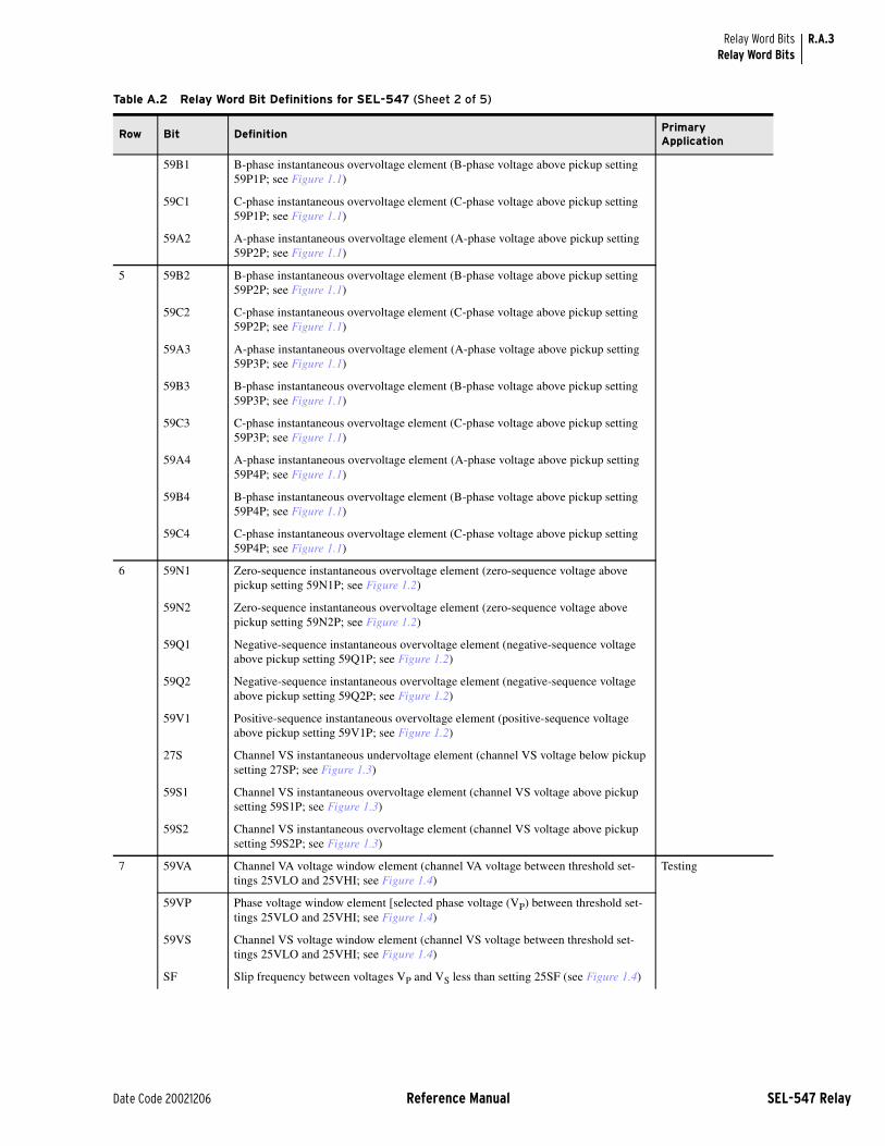
R.A.3
Date Code 20021206 Reference Manual SEL-547 Relay
Relay Word BitsRelay Word Bits
59B1 B-phase instantaneous overvoltage element (B-phase voltage above pickup setting 59P1P; see Figure 1.1)
59C1 C-phase instantaneous overvoltage element (C-phase voltage above pickup setting 59P1P; see Figure 1.1)
59A2 A-phase instantaneous overvoltage element (A-phase voltage above pickup setting 59P2P; see Figure 1.1)
5 59B2 B-phase instantaneous overvoltage element (B-phase voltage above pickup setting 59P2P; see Figure 1.1)
59C2 C-phase instantaneous overvoltage element (C-phase voltage above pickup setting 59P2P; see Figure 1.1)
59A3 A-phase instantaneous overvoltage element (A-phase voltage above pickup setting 59P3P; see Figure 1.1)
59B3 B-phase instantaneous overvoltage element (B-phase voltage above pickup setting 59P3P; see Figure 1.1)
59C3 C-phase instantaneous overvoltage element (C-phase voltage above pickup setting 59P3P; see Figure 1.1)
59A4 A-phase instantaneous overvoltage element (A-phase voltage above pickup setting 59P4P; see Figure 1.1)
59B4 B-phase instantaneous overvoltage element (B-phase voltage above pickup setting 59P4P; see Figure 1.1)
59C4 C-phase instantaneous overvoltage element (C-phase voltage above pickup setting 59P4P; see Figure 1.1)
6 59N1 Zero-sequence instantaneous overvoltage element (zero-sequence voltage above pickup setting 59N1P; see Figure 1.2)
59N2 Zero-sequence instantaneous overvoltage element (zero-sequence voltage above pickup setting 59N2P; see Figure 1.2)
59Q1 Negative-sequence instantaneous overvoltage element (negative-sequence voltage above pickup setting 59Q1P; see Figure 1.2)
59Q2 Negative-sequence instantaneous overvoltage element (negative-sequence voltage above pickup setting 59Q2P; see Figure 1.2)
59V1 Positive-sequence instantaneous overvoltage element (positive-sequence voltage above pickup setting 59V1P; see Figure 1.2)
27S Channel VS instantaneous undervoltage element (channel VS voltage below pickup setting 27SP; see Figure 1.3)
59S1 Channel VS instantaneous overvoltage element (channel VS voltage above pickup setting 59S1P; see Figure 1.3)
59S2 Channel VS instantaneous overvoltage element (channel VS voltage above pickup setting 59S2P; see Figure 1.3)
7 59VA Channel VA voltage window element (channel VA voltage between threshold set-tings 25VLO and 25VHI; see Figure 1.4)
Testing
59VP Phase voltage window element [selected phase voltage (VP) between threshold set-tings 25VLO and 25VHI; see Figure 1.4)
59VS Channel VS voltage window element (channel VS voltage between threshold set-tings 25VLO and 25VHI; see Figure 1.4)
SF Slip frequency between voltages VP and VS less than setting 25SF (see Figure 1.4)
Table A.2 Relay Word Bit Definitions for SEL-547 (Sheet 2 of 5)
Row Bit DefinitionPrimary Application

R.A.4
SEL-547 Relay Reference Manual Date Code 20021206
Relay Word BitsRelay Word Bits
25A1 Synchronism check element (see Figure 1.5) Close supervision
25A2 Synchronism check element (see Figure 1.5)
SFAST fP > fS (frequency VP > frequency VS; see Figure 1.4) Special Control Schemes
SSLOW fP ≤ fS (frequency VP ≤ frequency VS; see Figure 1.4)
8 81D1 Level 1 instantaneous frequency element (with corresponding pickup setting 81D1P; see Figure 1.8)
Testing
81D2 Level 2 instantaneous frequency element (with corresponding pickup setting 81D2P; see Figure 1.8)
81D3 Level 3 instantaneous frequency element (with corresponding pickup setting 81D3P; see Figure 1.8)
81D4 Level 4 instantaneous frequency element (with corresponding pickup setting 81D4P; see Figure 1.8)
81D5 Level 5 instantaneous frequency element (with corresponding pickup setting 81D5P; see Figure 1.8)
81D6 Level 6 instantaneous frequency element (with corresponding pickup setting 81D6P; see Figure 1.8)
27B81 Undervoltage element for frequency element blocking (A-phase voltage below pickup setting 27B81P; see Figure 1.7)
9 81D1T Level 1 definite-time frequency element 81D1T timed out (derived from 81D1; see Figure 1.8)
Tripping, Control
81D2T Level 2 definite-time frequency element 81D2T timed out (derived from 81D2; see Figure 1.8)
81D3T Level 3 definite-time frequency element 81D3T timed out (derived from 81D3; see Figure 1.8)
81D4T Level 4 definite-time frequency element 81D4T timed out (derived from 81D4; see Figure 1.8)
81D5T Level 5 definite-time frequency element 81D5T timed out (derived from 81D5; see Figure 1.8)
81D6T Level 6 definite-time frequency element 81D6T timed out (derived from 81D6; see Figure 1.8)
10 PWR1 Level 1 three-phase power element (see Figure 1.10) Tripping, Control
PWR2 Level 2 three-phase power element
PWR3 Level 3 three-phase power element
PWR4 Level 4 three-phase power element
11 SV1 SELOGIC control equation variable timer input SV1 asserted (see Figure 2.3) Testing, Seal-in functions, etc. (see Figure 2.6)SV2 SELOGIC control equation variable timer input SV2 asserted (see Figure 2.3)
SV3 SELOGIC control equation variable timer input SV3 asserted (see Figure 2.3)
SV4 SELOGIC control equation variable timer input SV4 asserted (see Figure 2.3)
SV1T SELOGIC control equation variable timer output SV1T asserted (see Figure 2.3) Tripping, Control; replacing traditional timersSV2T SELOGIC control equation variable timer output SV2T asserted (see Figure 2.3)
SV3T SELOGIC control equation variable timer output SV3T asserted (see Figure 2.3)
SV4T SELOGIC control equation variable timer output SV4T asserted (see Figure 2.3)
Table A.2 Relay Word Bit Definitions for SEL-547 (Sheet 3 of 5)
Row Bit DefinitionPrimary Application

R.A.5
Date Code 20021206 Reference Manual SEL-547 Relay
Relay Word BitsRelay Word Bits
12 SV5 SELOGIC control equation variable timer input SV5 asserted (see Figure 2.3) Testing, Seal-in functions, etc. (see Figure 2.6)SV6 SELOGIC control equation variable timer input SV6 asserted (see Figure 2.3)
SV7 SELOGIC control equation variable timer input SV7 asserted (see Figure 2.4)
SV8 SELOGIC control equation variable timer input SV8 asserted (see Figure 2.4)
SV5T SELOGIC control equation variable timer output SV5T asserted (see Figure 2.3) Tripping, Control; replacing traditional timersSV6T SELOGIC control equation variable timer output SV6T asserted (see Figure 2.3)
SV7T SELOGIC control equation variable timer output SV7T asserted (see Figure 2.4)
SV8T SELOGIC control equation variable timer output SV8T asserted (see Figure 2.4)
13 SV9 SELOGIC control equation variable timer input SV9 asserted (see Figure 2.4) Testing, Seal-in functions, etc. (see Figure 2.6)SV10 SELOGIC control equation variable timer input SV10 asserted (see Figure 2.4)
SV11 SELOGIC control equation variable timer input SV11 asserted (see Figure 2.4)
SV12 SELOGIC control equation variable timer input SV12 asserted (see Figure 2.4)
SV9T SELOGIC control equation variable timer output SV9T asserted (see Figure 2.4) Tripping, Control; replacing traditional timersSV10T SELOGIC control equation variable timer output SV10T asserted (see Figure 2.4)
SV11T SELOGIC control equation variable timer output SV11T asserted (see Figure 2.4)
SV12T SELOGIC control equation variable timer output SV12T asserted (see Figure 2.4)
14 SV13 SELOGIC control equation variable timer input SV13 asserted (see Figure 2.4) Testing, Seal-in functions, etc. (see Figure 2.6)SV14 SELOGIC control equation variable timer input SV14 asserted (see Figure 2.4)
SV15 SELOGIC control equation variable timer input SV15 asserted (see Figure 2.4)
SV16 SELOGIC control equation variable timer input SV16 asserted (see Figure 2.4)
SV13T SELOGIC control equation variable timer output SV13T asserted (see Figure 2.4) Tripping, Control; replacing traditional timersSV14T SELOGIC control equation variable timer output SV14T asserted (see Figure 2.4)
SV15T SELOGIC control equation variable timer output SV15T asserted (see Figure 2.4)
SV16T SELOGIC control equation variable timer output SV16T asserted (see Figure 2.4)
15 LT1 Latch Bit 1 asserted (see Figure 2.15) Control—replacing traditional latching relaysLT2 Latch Bit 2 asserted (see Figure 2.15)
LT3 Latch Bit 3 asserted (see Figure 2.15)
LT4 Latch Bit 4 asserted (see Figure 2.15)
LT5 Latch Bit 5 asserted (see Figure 2.15)
LT6 Latch Bit 6 asserted (see Figure 2.15)
LT7 Latch Bit 7 asserted (see Figure 2.15)
LT8 Latch Bit 8 asserted (see Figure 2.15)
16 LT9 Latch Bit 9 asserted (see Figure 2.15) Control—replacing traditional latching relaysLT10 Latch Bit 10 asserted (see Figure 2.15)
LT11 Latch Bit 11 asserted (see Figure 2.15)
LT12 Latch Bit 12 asserted (see Figure 2.15)
LT13 Latch Bit 13 asserted (see Figure 2.15)
LT14 Latch Bit 14 asserted (see Figure 2.15)
LT15 Latch Bit 15 asserted (see Figure 2.15)
LT16 Latch Bit 16 asserted (see Figure 2.15)
Table A.2 Relay Word Bit Definitions for SEL-547 (Sheet 4 of 5)
Row Bit DefinitionPrimary Application

R.A.6
SEL-547 Relay Reference Manual Date Code 20021206
Relay Word BitsRelay Word Bits
17 RB1 Remote Bit 1 asserted (see Figure 2.11) Control via serial port
RB2 Remote Bit 3 asserted (see Figure 2.11)
RB3 Remote Bit 4 asserted (see Figure 2.11)
RB4 Remote Bit 5 asserted (see Figure 2.11)
RB5 Remote Bit 6 asserted (see Figure 2.11)
RB6 Remote Bit 7 asserted (see Figure 2.11)
RB7 Remote Bit 8 asserted (see Figure 2.11)
RB8 Remote Bit 8 asserted (see Figure 2.11)
18 RB9 Remote Bit 9 asserted (see Figure 2.11) Control via serial port
RB10 Remote Bit 10 asserted (see Figure 2.11)
RB11 Remote Bit 11 asserted (see Figure 2.11)
RB12 Remote Bit 12 asserted (see Figure 2.11)
RB13 Remote Bit 13 asserted (see Figure 2.11)
RB14 Remote Bit 14 asserted (see Figure 2.11)
RB15 Remote Bit 15 asserted (see Figure 2.11)
RB16 Remote Bit 16 asserted (see Figure 2.11)
19 SG1 Setting Group 1 active (see Table 2.5) Indication
SG2 Setting Group 2 active (see Table 2.5)
OC Asserts 1/4 cycle for Open Command execution Testing, Control
CC Asserts 1/4 cycle for Close Command execution
CLKPUL Asserts momentarily for 16 msec. at regular intervals, corresponding to setting INTRVL (Clock Pulse Interval)
Automatic LED lamp test
IAMET Channel IA high-gain mode active (asserts at threshold just below 0.6A) Embedded in event report logic
Table A.2 Relay Word Bit Definitions for SEL-547 (Sheet 5 of 5)
Row Bit DefinitionPrimary Application

Date Code 20021206 SEL-547 Relay
Index
Page numbers appearing in bold mark the location of the topic’s primary discussion.
U=User’s Guide; R=Reference Manual
Symbols>, trigger row R.3.15
AAcceptance Testing U.4.2
See also Testing
ACCESS Command U.3.5, R.7.2, R.7.3, R.7.6
Access Levels R.7.20, 1, B levels U.3.5
Accuracy
metering U.1.17
ALARM
relay output R.2.31, R.7.6, R.8.3
Applications
generator site U.1.12–U.1.15transfer switch U.1.5–U.1.12
ASCII Commands U.3.5, R.7.1See also Commands
response header U.3.4
ASCII Protocol R.5.3See also Communication
Automatic Messages
serial port R.5.18
CCable, Serial R.4.3
See also Communication
CASCII Command R.5.4
CEVENT Command R.5.8See also Event Report
CHISTORY Command R.5.7See also Event History
CLOSE Command R.7.15
Commands
2ACCESS R.7.3, R.7.6
ACCESS R.7.2, R.7.3, R.7.6
BACCESS R.7.2, R.7.3, R.7.6
CASCII R.5.4–R.5.6CEVENT R.5.8CHISTORY R.5.7CLOSE R.7.15CONTROL R.7.16COPY R.7.16
CSTATUS R.5.7
DATE U.3.9, R.7.7EVENT R.7.7GROUP R.7.17
HISTORY R.7.7METER U.3.25, R.7.8OPEN R.7.15PASSWORD U.3.6, R.7.18PULSE R.7.15QUIT R.7.8SER U.3.27, R.7.8SET R.7.19
SHOWSET R.7.9STATUS R.7.11TARGET R.7.12TIME U.3.9, R.7.14TRIGGER R.7.14VERSION R.7.19
Commission Testing U.4.2See also Testing
Communication
ASCII Commands R.7.1See Commands
cable U.3.3, R.4.3
communications protocols R.5.3–R.5.17
LMD R.5.9See Distributed Port Switch
Modbus RTU R.6.1–R.6.22See also Modbus RTU
pinouts
EIA-232 R.4.2
EIA-485 R.4.2
Compressed ASCII R.5.4See also Commands
Connection
ac/dc diagram U.2.6
alarm output U.2.6
communications ports R.4.2
contact outputs U.2.6
grounding U.2.3optoisolated inputs U.2.6
power U.2.3, U.3.2serial port U.2.3, U.3.3terminal block U.2.3test connections U.4.4wire size U.2.4
Contact Inputs
See Optoisolated Inputs
Contact Outputs U.2.5
connections U.2.6
pulsing U.3.28, R.7.15ratings U.1.16
Control Outputs
See Contact Outputs
Control Switches
See Local Control
COPY Command R.7.16
CSTATUS Command R.5.7
Current Transformer
connection U.2.6
ratio U.3.13
DDATE Command U.3.9, R.7.7
Dimensions U.2.2
Distributed Port Switch R.5.9
EEarthing
See Grounding
EIA-232
See Communication
EIA-485
See Communication
EVE Command R.3.5See also Event
Event R.3.1–R.3.20ER equation R.3.3
EVE Command R.3.5, R.7.7PULSE n initiate R.3.4
trigger, TRI command R.7.14
Event History R.7.7See also Event
CHISTORY Command R.5.7HIS Command R.7.7
Event Report R.3.1–R.3.20>, trigger row R.3.15See also Event
column definitions R.3.7
Compressed ASCII CEVENT R.5.8phasor calculation R.3.19

IN.2 Index
SEL-547 Relay Date Code 20021206
retrieving event data R.3.5
application example R.3.15–R.3.17
summary section R.3.4trigger R.7.14
Event Summary R.3.4See also Event
contents R.3.5
event type R.3.4
EZ Settings U.3.10–U.3.24changing settings U.3.10
default U.3.11
disable U.3.11
relationship to group and global R.8.4–R.8.10
settings sheet U.C.1
FFactory Assistance U.4.8
Fast Meter R.5.10 See also SEL Binary Protocols
Fast Operate R.5.14–R.5.17See also SEL Binary Protocols
Firmware Versions U.A.1upgrading instructions U.B.1
VER command R.7.19
Frequency Elements R.1.18–R.1.21
Front Panel
lamp test R.2.32
layout U.2.3
LEDs U.3.29
GGenerator Site Application U.1.12
Grounding U.2.3
GROUP Command R.7.17
HHelp U.4.8
HIS Command R.7.7See also Event History
II/O
See Input/Output
Input Processing R.2.10
Input/Output R.2.12, R.2.30
Installation U.2.1–U.2.7dimensions U.2.2
LLatch Bits R.2.17–R.2.24
See also Local Control
LEDs
front panel U.3.29, R.2.32targets R.2.32
LMD
See Distributed Port Switch
Local Control R.2.17–R.2.24application example R.2.22
nonvolatile R.2.22
operate control switches R.2.17
Low-Level Test Interface U.4.4
MMaintenance Testing U.4.3
See also Testing
Meter
accuracy U.1.17
view metering U.3.25
METER Command U.3.25, R.7.8
Modbus RTU R.6.1–R.6.22
Multidrop Network
See Modbus RTU
Multiple Settings Groups R.2.25
COPY command R.7.16
GROUP command R.7.17
indication R.2.25
nonvolatile R.2.29
selecting R.2.25
OOPEN Command R.7.15
Optoisolated Inputs U.2.4, R.2.12–R.2.14
connections U.2.6
debounce R.2.12
settings example R.2.12
Output Contacts R.2.30ALARM output R.2.31
PPassword
defaults U.3.5disable U.3.7
PASSWORD Command U.3.6, R.7.18
Power Elements R.1.22–R.1.23
Power Supply U.1.16
Processing Interval R.2.10
PULSE Command R.7.15
QQUIT Command R.7.8
RRelay Word Bits R.A.1–R.A.6
alphanumeric list R.A.2–R.A.6
in SELOGIC control equations R.2.2
Remote Bits R.2.15CON command R.7.16settings change effects R.2.16
states R.2.15
volatile R.2.16
SSchweitzer Engineering Laboratories
contact information U.4.8
SEL Binary Protocols
Fast Meter R.5.10Fast Operate R.5.14
SEL-547 Relay
block diagram U.1.2features U.1.2
Self-Tests U.4.6See also Testing
SELOGIC Control Equations R.2.2–R.2.11
applications examples R.2.8
capacity R.2.10
disabling R.2.10
operators R.2.3
processing R.2.10
Relay Word bits R.2.2
timers R.2.6
variables R.2.6
Sequential Events Recorder
See SER (Sequential Events Recorder)
SER (Sequential Events Recorder) R.3.12–R.3.14
example report R.3.20
SER command R.7.8setting R.3.12
trigger R.3.12
SER Command U.3.27, R.7.8
Serial Port
See Communication
Serial Port Commands
See Communication
Setting
See also EZ Settings
CT ratio U.3.13
date U.3.9
frequency U.3.14
from serial port R.8.2
groups R.2.25–R.2.28
phase rotation U.3.14
relay ID U.3.12

IN.3Index
Date Code 20021206 SEL-547 Relay
SET command R.7.19, R.8.1–R.8.3sheets R.SET.1
terminal ID U.3.12
TERSE U.3.10
time U.3.9
SHO Command R.7.9
Specifications U.1.16
STA Command U.3.8, R.7.11
Status
check relay status U.3.8
Status Failure U.3.8, U.4.6
Status Warning U.3.8, U.4.6
Synchronism Check Elements R.1.7–R.1.17
TTARGET Command R.7.12
Targets
See TARGET Command
Technical Service Center U.4.8
Terminal Blocks
tightening torque U.2.4
Testing U.4.2–U.4.6acceptance testing U.4.2commissioning testing U.4.2low-level test interface U.4.4maintenance testing U.4.3methods U.4.4–U.4.5
self-tests U.4.6with LEDs U.3.29
with output contacts U.4.5
with SER U.4.5
TIME Command R.7.14
Timers
See SELOGIC Control Equations
Transfer Switch Application U.1.5
TRI Command R.7.14
Troubleshooting U.4.7
VVER Command R.7.19
Voltage Elements R.1.2–R.1.6

This page intentionally left blank

Date Code 20021206 SEL-547 Relay
SEL-547 Relay Command Summary
Command Description
Access Level 0 Command
Access Level 0 is the initial relay access level. The relay automatically returns to Access Level 0 when a serial port time-out setting expires or after a QUIT command. The screen action prompt is: =
ACC Enter Access Level 1. The relay prompts the user for the Access Level 1 password in order to enter Access Level 1.
Access Level 1 Commands
The Access Level 1 commands allow the user to look at settings information and not change it, and to retrieve and reset event, recorder, and metering data. The screen action prompt is: =>
2AC Enter Access Level 2. The relay prompts for the entry of the Access Level 2 password in order to enter Access Level 2.
BAC Enter Breaker Access Level (Access Level B). The relay prompts the user for the Access Level B password.
DAT Show date.
DAT mm/dd/yy Enter date in this manner if global Date Format setting, DATE_F, is set to MDY.
DAT yy/mm/dd Enter date in this manner if global Date Format setting, DATE_F, is set to YMD.
EVE n Show event report n with 4 samples per cycle (n = 1 to highest numbered event report, where 1 is the most recent report: see HIS command). If n is omitted, (EVE command) most recent report is displayed.
EVE n R Show event report n in raw (unfiltered) format with 16 samples per cycle resolution.
EVE n C Show event report n in compressed ASCII format for use with the SEL-5601 Analytic Assistant.
EVE n A Show event report n with analog section only.
EVE n Sx Show event report n with x samples per cycle (x = 4 or 16).
EVE n L Show event report n with 16 samples per cycle (similar to EVE n S16).
EVE n Ly Show first y cycles of event report n (y = 1 to global setting LER).
EVE n V Show event report n with variable scaling for analog values.
GRO Display active group number.
HIS n Show brief summary of n latest event reports, where 1 is the most recent entry. If n is not specified, (HIS command) all event summaries are displayed.
HIS C Clear all event reports from nonvolatile memory.
MET k Display instantaneous metering data. Enter k for repeat count (k = 1–32767, if not specified, default is 1).
QUI Quit. Returns to Access Level 0. Terminates SEL Distributed Port Switch Protocol (LMD) connection.
SER Show entire Sequential Events Recorder (SER) report.
SER n Show latest n rows in the SER report (n = 1–512, where 1 is the most recent entry).
SER m n Show rows m through n in the SER report (m = 1–512).
SER d1 Show all rows in the SER report recorded on the specified date (see DAT command for date format).
SER d1 d2 Show all rows in the SER report recorded between dates d1 and d2, inclusive.
SER C Clears SER report from nonvolatile memory.
SHO n Show relay settings (voltage, frequency, timers, etc.) for Group n (n = 1-2, if not specified, default is active setting group).
SHO n L Show SELOGIC® control equation settings for Group n (n = 1-2, if not specified, default is the SELOGIC control equations for the active setting group).
SHO G Show global settings.
SHO R Show SER and settings.
SHO P p Show serial port p settings, (p = 1 or F, if not specified, default is active port).
SHO ... name For all SHO commands, jump ahead to specific setting by entering setting name.

2
SEL-547 Relay Date Code 20021206
SEL-547 Relay Command Summary
STA Show relay self-test status.
TAR n k Display Relay Word row. If n = 0–62, display row n. If n is an element name (e.g., 50A1) display row containing element n. Enter k for repeat count
(k = 1–32767, if not specified, default is 1).
TAR LIST Shows all the Relay Words in all of the rows.
TAR ROW . . . Shows the Relay Word row number at the start of each line, with other selected Target commands as described above, such as n, name, k, and LIST.
TIM Show or set time (24 hour time). Show current relay time by entering TIM. Set the current time by entering TIM followed by the time of day (e.g., set time 22:47:36 by entering TIM 22:47:36).
TRI Trigger an event report.
Access Level B Commands
Access Level B commands primarily allow the user to operate the output contacts and change port and EZ settings. All Access Level 1 commands can also be executed from Access Level B. The screen action prompt is: ==>
CLO Close circuit breaker (assert Relay Word bit CC).
OPE Open circuit breaker (assert Relay Word bit OC).
PUL n k OUT201–OUT212) for k seconds. Specify parameter n; k = 1–30 seconds; if not specified, default is 1.
SET Change relay EZ settings.
SET P p Change serial port p settings, (p = 1 or F, if not specified, default is active port).
Access Level 2 Commands
The Access Level 2 commands allow unlimited access to relay settings, parameters, and output contacts. All Access Level 1 and Access Level B commands are available from Access Level 2. The screen action prompt is: =>>
CON n Control Relay Word bit RBn (Remote Bit n; n = 1–16). Execute CON n and the relay responds: CONTROL RBn. Then reply with one of the following:
SRB n set Remote Bit n (assert RBn).
CRB n clear Remote Bit n (deassert RBn).
PRB n pulse Remote Bit n [assert RBn for 1/4 cycle].
COP m n Copy relay and logic settings from group m to group n (m and n are numbers 1–6).
GRO n Change active group to group n (n = 1–2).
PAS Show existing Access Level 1, Level B, and Level 2 passwords.
PAS 1 xxxxxx Change Access Level 1 password to xxxxxx.
PAS B xxxxxx Change Access Level B password to xxxxxx.
PAS 2 xxxxxx Change Access Level 2 password to xxxxxx.
Entering DISABLE as the password disables the password requirement for the specified access level.
SET n Change relay settings (voltage, frequency, timers, etc.) for group n (n = 1–2, if not specified, default is active setting group).
SET n L Change SELOGIC control equation settings for group n (n = 1–2, if not specified, default is the SELOGIC control equations for the active setting group).
SET G Change global settings.
SET R Change SER settings.
SET ... name For all SET commands, jump ahead to specific setting by entering setting name.
SET ... TERSE For all SET commands, TERSE disables the automatic SHO command after settings entry.
STA C Resets self-test warnings/failures and reboots the relay.
VER Show relay configuration and firmware version.
Command Description

3
Date Code 20021206 SEL-547 Relay
SEL-547 Relay Command Summary
Key Stroke Commands
Ctrl-Q Send XON command to restart communications port output previously halted by XOFF.
Ctrl-S Send XOFF command to pause communications port output.
Ctrl-X Send CANCEL command to abort current command and return to current access level action prompt.
Key Stroke Commands When Using SET Command
<ENTER> Retains setting and moves on to next setting.
^ <ENTER> Returns to previous setting.
< <ENTER> Returns to previous setting section.
> <ENTER> Skips to next setting section.
END <ENTER> Exits setting editing session, then prompts user to save settings.
Ctrl-X Aborts setting editing session without saving changes.
Command Description

This page intentionally left blank