
On Reducing the Global State Graph for Verification of Distributed Computations
ABSTRACTAn effective methodology for design verification and productvalidation is always a key to high quality products. As manybody control applications are currently implemented acrossmultiple ECUs distributed on one or more vehicle networks,verification and validation of vehicle-level user functions willrequire availability of both the vehicle networks and multipleECUs involved in the implementation of the user functions.While the ECUs are usually developed by different suppliersand vehicle networks' infrastructure and communicationprotocols are normally maintained and developed by theOEM, each supplier will be faced with a similar challenge -the ECU being developed cannot be fully verified and testeduntil all other ECUs and their communication networks areavailable in the final development stage. In such cases, manydesign and implementation errors associated with each ECUand their interactive functions cannot be identified prior tovehicle-level integration testing, at which time cost of fixingerrors would be high for each supplier involved. The errorsthat are not discovered during integration testing willconsequently affect product quality and timely delivery. Evenif all the ECUs are available and work for their “happypaths”, it will still be challenging to validate the ECU'scapability of handling fault conditions. Therefore, a faultinsertion testing strategy is essential to fully meet customer'sexpectations and robust design.
This paper describes a methodology for developing bodycontrol applications based on the concept of executablespecification, plant modeling, test case generation usingvarious means, and migration of test cases in the virtual testharness model to ECU-in-the-loop testing environment.Unique aspects of the plant modeling, test case developmentstrategies and their value are discussed in this context. Forexample, behavior models of other ECUs on the vehiclenetwork, fault conditions, and commands from an external
diagnostic device into the plant models are incorporated toenable verification of distributed body control applications.For verification, the use of Stateflow for test casedevelopment and test case reuse for both requirementsverification and ECU in-the-loop testing are also discussed.The methodology described in this paper has beensuccessfully applied to production projects.
INTRODUCTIONAutomotive body-control functions of a modern vehicle arenowadays implemented with multiple ECUs that are logicallyinterconnected through one or more vehicle communicationnetworks [1]. As reducing the number of ECUs utilized in avehicle is a goal, it is becoming a trend to integrate andimplement more user functions into one ECU [2], thanks topowerful multi-core CPUs and large memory space in today'smicrocontrollers. On the other hand, there also exists a trendwhere an increasing number of ECUs are employed, due tothe need of decomposing vehicle-level user functions intomultiple functional blocks which are thus to be implementedand distributed across multiple ECUs. Such a need may beoriginated from both technical and business perspectivesincluding modular architectural design philosophy, visibilityrequirement for interactive signals among ECUs, reusabilityof ECUs for different product lines, protections for OEMs'IPs, vehicle architectural design flexibility, etc. Therefore, theindustry sees such two opposite trends in vehicle architecturaldesign, which may be termed “centralized design” and“distributed design”.
While the total number of body-control ECUs utilized in avehicle does not significantly go up or go down due to theconfluence of two opposite driving forces behind the twotrends, the force driving the number to increase appears to bemore dominant. The only trend that is definitive here is thatthe complexity of interactions among the ECUs on vehiclenetworks has significantly increased in recent years [3].
A Systems Engineering Approach to Verification ofDistributed Body Control Applications Development
2010-01-2328Published
10/19/2010
Jinming Yang, Jason Bauman and Al BeydounLear Corporation
Copyright © 2010 SAE International
Moreover, the distributed design approach requires securitychecks and handshakes between ECUs which further addscomplexity to the vehicle system. Such a trend in vehiclesystem design presents new technical challenges for theverification and validation processes. As a result, to verify thedesigns and validate the user functions, engineers will needall the ECUs involved in implementing the user functions tobe available. While most of the ECUs would be unavailableduring the design and implementation phases because most ofthem are designed and implemented by different suppliers[4], each ECU supplier would be faced with similardifficulties in identifying issues existent in functional designand interactive behaviors among the ECUs and/orsubsystems. Consequently, any potential design andimplementation issues that should have been identified in theindividual ECU development stage would have to beidentified and resolved in the vehicle validation andintegration stages [5]. Undoubtedly, the failure of earlyidentification of design and integration issues will not onlymake the development cost much higher but also inevitablyaffect product quality and timely delivery.
Another dilemma in this respect lies in design verificationand validation of fault handling capability [6]. Due to thedistributed functions across the vehicle networks, each ECUwill have to be capable of handling faults caused by raceconditions, deadlocks, missing messages, etc [7]. Once again,without the availability of its surrounding and workableECUs, the vehicle-level design and fault handling capabilitycannot be fully verified in the early development stages.More importantly, even in the final vehicle-level validationand integration stages, certain fault conditions may not beeasy and/or possible to be created with the ECUs (that mostlikely function properly and without faults), thereforevalidating the fault handling capability still remains achallenge. After all, it is always crucial to fully validate theexception handling capability, which is the key to vehiclereliability and safety.
In this paper, a model-based methodology to address theissues and challenges described above will be presented. Themethods include creating test cases in various developmentstages, using plant models1 [8] to run model-in-the-loopsimulations, inserting faults to plant models, reusing the testcases for hardware-in-the-loop (HIL) testing and validation,and dynamically deploying test cases on the HIL tester. Thenovelty in this work exits in design verification and productvalidation for the distributed type of body-control ECUs byleveraging plant models and the fault insertion method. Theuse of virtual test harness models for test case creation and
reuse are also emphasized in this paper. Other unique aspectsdiscussed in this paper include the following:
• Generate test vectors by collecting simulated data fromvirtual test harness models. Such test vectors are thenconverted into reusable test cases.
• Add fault controls to plant models in order to create faultconditions to the ECU(s) being developed and tested.
• Reuse the plant models for ECU in-the-loop testing byimporting plant models to the HIL tester. The test casescreated in the virtual test harness environment can be reusedfor the HIL testing.
• Resolve test sequence and dependency issues by usingStateflow model to do both test vector generation and resultschecking.
• Project management aspects such as number of reusable testcases, creating test cases for requirement changes, plantmodeling as a new activity in model-based design process,tackling issues for design changes and design variants, andseeking customer support for plant modeling.
In this work, the MathWorks' toolset including Simulink®/Stateflow® and MATLAB programming language was used.The methodology introduced in this paper has beensuccessfully applied to production projects.
A CASE STUDY OF DISTRIBUTEDUSER FUNCTIONSAs stated earlier in this context, there exist valid reasonsincluding both technical reasons and business reasons whyuser functions are implemented across multiple ECUs. Herethe passive start function2 is taken as an example for the saidvehicle user function which has become an important user-convenience feature in recent years. In general, when thedriver presses the vehicle start button trying to start thevehicle, the BCM will send a signal to the ECU responsiblefor the passive functions (i.e., passive entry and passive startor PEPS). The PEPS ECU will then trigger another ECU totransmit wireless LF signals to the vicinity where the passivekey (i.e., a remote keyless entry device) can be located. Afterthe passive key receives the valid challenges, it sends backRF signals to the wireless receiver ECU. If the passive key isauthenticated per its encrypted/decrypted algorithm, the BCMinitiates the authentication with the power-train ECU. At thistime, the BCM ECU may check additional preconditionsrequired for passive start from other ECUs includingtransmission ECU, the cluster instrument ECU, or otherECUs possessing relevant information. Therefore, the passive
1The terms “plant” and “controller” primarily employed in control theory for the closed-loop type of control systems have been adopted in model-based design to refer to surrounding systemsthat interact with the system under developed in a non-strict sense. Both “plant” and “plant models” are used in the references.2Note that all the vehicle functions described here are general information and knowledge which is available in public domains and special care has been taken to ensure no proprietaryinformation to be disclosed in this context.
start user function may involve the BCM ECU, PEPS ECU,receiver ECU, power-train ECU, transmission ECU, clusterECU, and more. In a typical vehicle with the passive startfunction, the feature normally involves sub-functions acrossan average of 5 ECUs, or up to 40 unit models distributed onmultiple ECUs from the modeling perspective. The unitmodels mentioned here that were created according to theadopted modeling guideline, consist of a set of Simulinkblocks or Stateflow models with a defined manageablecomplexity which may generate 50 to 300 lines of code(excluding lines of comments).
Besides the passive start function, the BCM may also need toinclude many other functions such as remote start, locking,wipers, lighting, alarming and warning, battery management,etc. Each of these functions may involve other ECUs on thevehicle network(s) and further complicates the system designfor the ECU being developed.
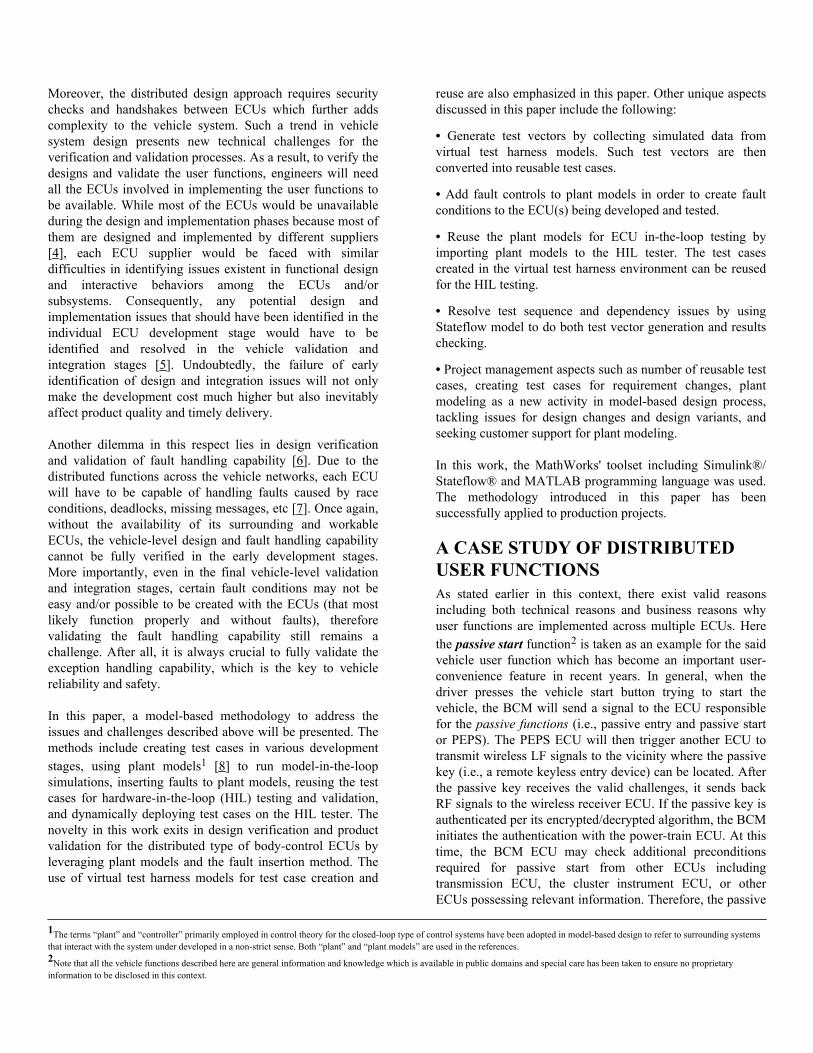
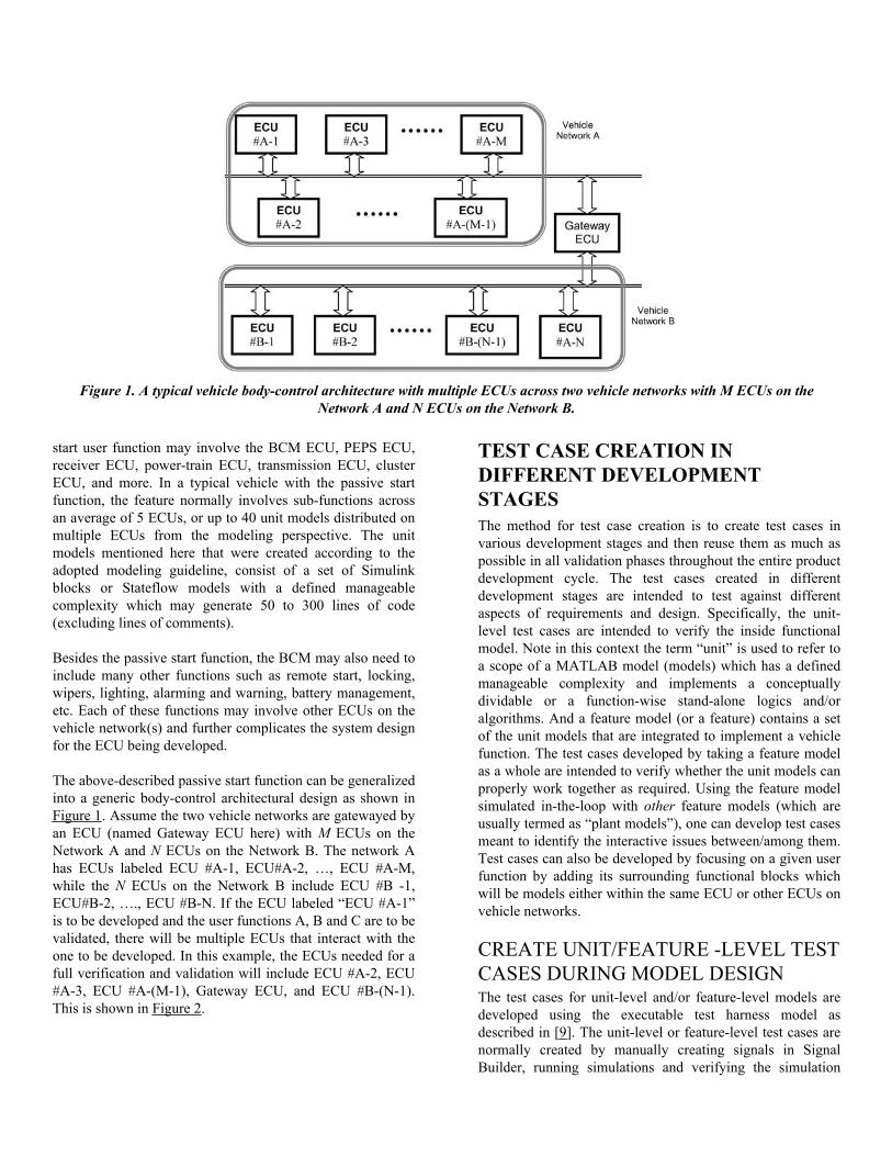
The above-described passive start function can be generalizedinto a generic body-control architectural design as shown inFigure 1. Assume the two vehicle networks are gatewayed byan ECU (named Gateway ECU here) with M ECUs on theNetwork A and N ECUs on the Network B. The network Ahas ECUs labeled ECU #A-1, ECU#A-2, …, ECU #A-M,while the N ECUs on the Network B include ECU #B -1,ECU#B-2, …., ECU #B-N. If the ECU labeled “ECU #A-1”is to be developed and the user functions A, B and C are to bevalidated, there will be multiple ECUs that interact with theone to be developed. In this example, the ECUs needed for afull verification and validation will include ECU #A-2, ECU#A-3, ECU #A-(M-1), Gateway ECU, and ECU #B-(N-1).This is shown in Figure 2.
TEST CASE CREATION INDIFFERENT DEVELOPMENTSTAGESThe method for test case creation is to create test cases invarious development stages and then reuse them as much aspossible in all validation phases throughout the entire productdevelopment cycle. The test cases created in differentdevelopment stages are intended to test against differentaspects of requirements and design. Specifically, the unit-level test cases are intended to verify the inside functionalmodel. Note in this context the term “unit” is used to refer toa scope of a MATLAB model (models) which has a definedmanageable complexity and implements a conceptuallydividable or a function-wise stand-alone logics and/oralgorithms. And a feature model (or a feature) contains a setof the unit models that are integrated to implement a vehiclefunction. The test cases developed by taking a feature modelas a whole are intended to verify whether the unit models canproperly work together as required. Using the feature modelsimulated in-the-loop with other feature models (which areusually termed as “plant models”), one can develop test casesmeant to identify the interactive issues between/among them.Test cases can also be developed by focusing on a given userfunction by adding its surrounding functional blocks whichwill be models either within the same ECU or other ECUs onvehicle networks.
CREATE UNIT/FEATURE -LEVEL TESTCASES DURING MODEL DESIGNThe test cases for unit-level and/or feature-level models aredeveloped using the executable test harness model asdescribed in [9]. The unit-level or feature-level test cases arenormally created by manually creating signals in SignalBuilder, running simulations and verifying the simulation
Figure 1. A typical vehicle body-control architecture with multiple ECUs across two vehicle networks with M ECUs on theNetwork A and N ECUs on the Network B.
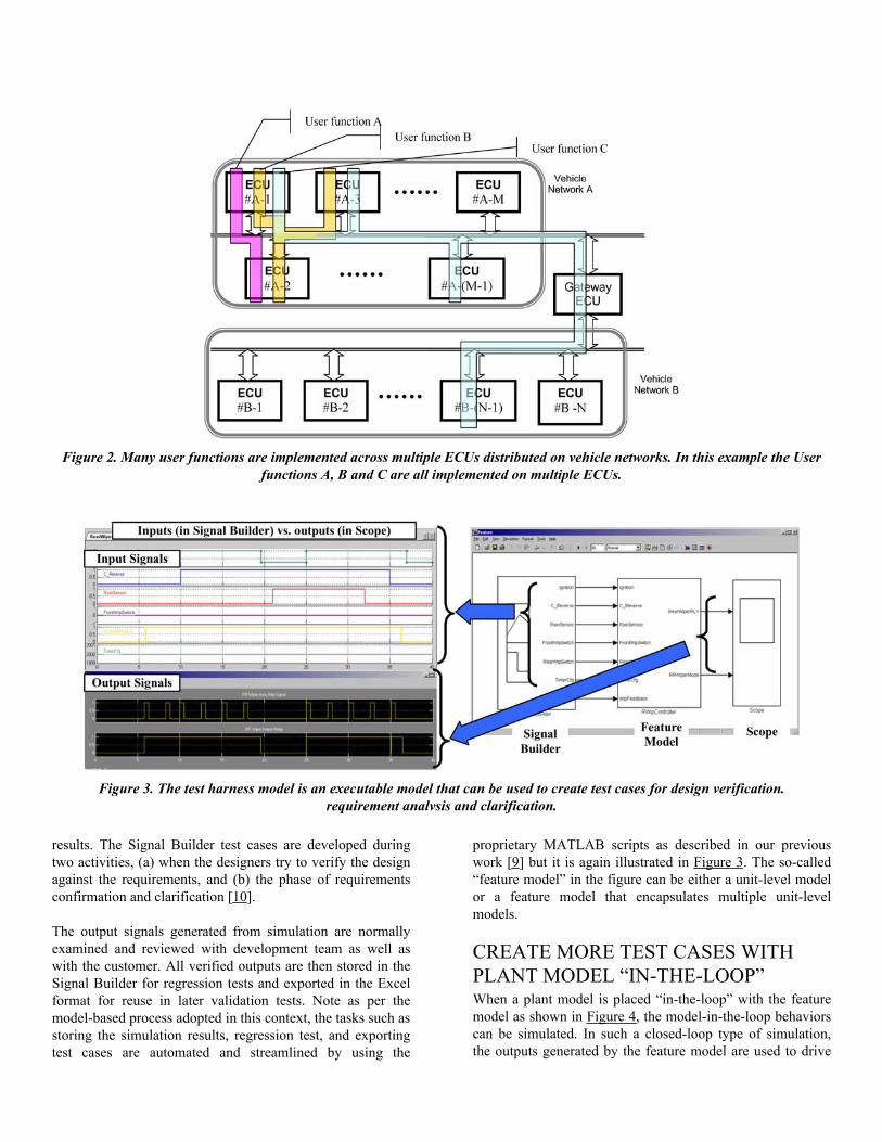
results. The Signal Builder test cases are developed duringtwo activities, (a) when the designers try to verify the designagainst the requirements, and (b) the phase of requirementsconfirmation and clarification [10].
The output signals generated from simulation are normallyexamined and reviewed with development team as well aswith the customer. All verified outputs are then stored in theSignal Builder for regression tests and exported in the Excelformat for reuse in later validation tests. Note as per themodel-based process adopted in this context, the tasks such asstoring the simulation results, regression test, and exportingtest cases are automated and streamlined by using the
proprietary MATLAB scripts as described in our previouswork [9] but it is again illustrated in Figure 3. The so-called“feature model” in the figure can be either a unit-level modelor a feature model that encapsulates multiple unit-levelmodels.
CREATE MORE TEST CASES WITHPLANT MODEL “IN-THE-LOOP”When a plant model is placed “in-the-loop” with the featuremodel as shown in Figure 4, the model-in-the-loop behaviorscan be simulated. In such a closed-loop type of simulation,the outputs generated by the feature model are used to drive
Figure 2. Many user functions are implemented across multiple ECUs distributed on vehicle networks. In this example the Userfunctions A, B and C are all implemented on multiple ECUs.
Figure 3. The test harness model is an executable model that can be used to create test cases for design verification.requirement analvsis and clarification.
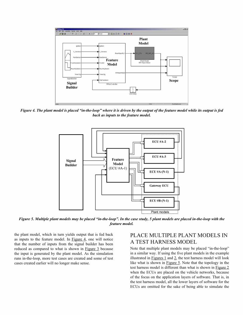
the plant model, which in turn yields output that is fed backas inputs to the feature model. In Figure 4, one will noticethat the number of inputs from the signal builder has beenreduced as compared to what is shown in Figure 3 becausethe input is generated by the plant model. As the simulationruns in-the-loop, more test cases are created and some of testcases created earlier will no longer make sense.
PLACE MULTIPLE PLANT MODELS INA TEST HARNESS MODELNote that multiple plant models may be placed “in-the-loop”in a similar way. If using the five plant models in the exampleillustrated in Figures 1 and 2, the test harness model will looklike what is shown in Figure 5. Note that the topology in thetest harness model is different than what is shown in Figure 2when the ECUs are placed on the vehicle networks, becauseof the focus on the application layers of software. That is, inthe test harness model, all the lower layers of software for theECUs are omitted for the sake of being able to simulate the
Figure 4. The plant model is placed “in-the-loop” where it is driven by the output of the feature model while its output is fedback as inputs to the feature model.
Figure 5. Multiple plant models may be placed “in-the-loop”. In the case study, 5 plant models are placed in-the-loop with thefeature model.
ECUs in the closed loops. Similar to the previous case withonly one plant model being in-the-loop, the number of inputshas been further reduced and some of the inputs are replacedby the outputs from the plant models. Therefore, the testcases created in this test harness will be closer to system-leveltest cases.
Note that the test cases created here may have lower coveragerate for the feature model, however the test cases are moremeaningful to reflect the interactive aspects among the ECUsas well as potential issues associated with the service anddriver layers when they are ported to hardware in-the-looptesting and validation.
FAULT INSERTION USING PLANTMODELSAs described earlier, it is both necessary and beneficial tocreate fault conditions using plant models. The fault controlto the plant models can be added in order to simulate the faultcases for the feature model. When the plant model issimulated in-the-loop and fault control is added, more testcases can be added. Note there will be more implications todesign verification and ECU validation for the followingreasons:• Even if the other ECUs are available in the final validationphase, fault conditions from other ECUs cannot be easilycreated (as the ECUs most likely operate properly), so thecapability of handling fault conditions cannot be validatedwithout simulations in the virtual test harness environment.• Besides fault conditions, race conditions from other ECUsare not easily created.• It is often challenging to duplicate issues found in pre-production - manipulating plant models by controlling theirfault conditions makes it possible/easier to duplicate specificissues.
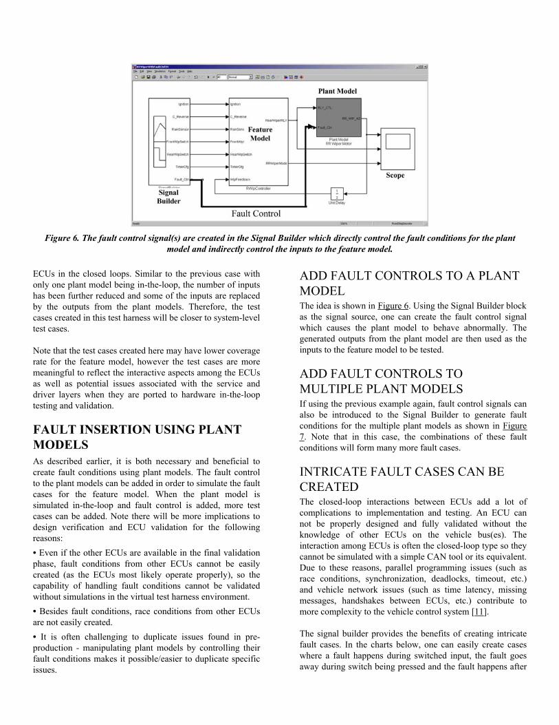
ADD FAULT CONTROLS TO A PLANTMODELThe idea is shown in Figure 6. Using the Signal Builder blockas the signal source, one can create the fault control signalwhich causes the plant model to behave abnormally. Thegenerated outputs from the plant model are then used as theinputs to the feature model to be tested.
ADD FAULT CONTROLS TOMULTIPLE PLANT MODELSIf using the previous example again, fault control signals canalso be introduced to the Signal Builder to generate faultconditions for the multiple plant models as shown in Figure7. Note that in this case, the combinations of these faultconditions will form many more fault cases.
INTRICATE FAULT CASES CAN BECREATEDThe closed-loop interactions between ECUs add a lot ofcomplications to implementation and testing. An ECU cannot be properly designed and fully validated without theknowledge of other ECUs on the vehicle bus(es). Theinteraction among ECUs is often the closed-loop type so theycannot be simulated with a simple CAN tool or its equivalent.Due to these reasons, parallel programming issues (such asrace conditions, synchronization, deadlocks, timeout, etc.)and vehicle network issues (such as time latency, missingmessages, handshakes between ECUs, etc.) contribute tomore complexity to the vehicle control system [11].
The signal builder provides the benefits of creating intricatefault cases. In the charts below, one can easily create caseswhere a fault happens during switched input, the fault goesaway during switch being pressed and the fault happens after
Figure 6. The fault control signal(s) are created in the Signal Builder which directly control the fault conditions for the plantmodel and indirectly control the inputs to the feature model.
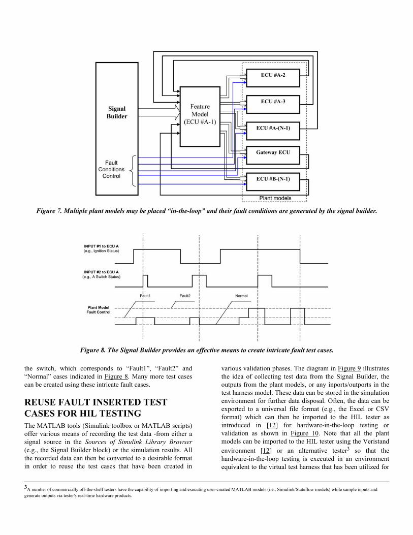
the switch, which corresponds to “Fault1”, “Fault2” and“Normal” cases indicated in Figure 8. Many more test casescan be created using these intricate fault cases.
REUSE FAULT INSERTED TESTCASES FOR HIL TESTINGThe MATLAB tools (Simulink toolbox or MATLAB scripts)offer various means of recording the test data -from either asignal source in the Sources of Simulink Library Browser(e.g., the Signal Builder block) or the simulation results. Allthe recorded data can then be converted to a desirable formatin order to reuse the test cases that have been created in
various validation phases. The diagram in Figure 9 illustratesthe idea of collecting test data from the Signal Builder, theoutputs from the plant models, or any inports/outports in thetest harness model. These data can be stored in the simulationenvironment for further data disposal. Often, the data can beexported to a universal file format (e.g., the Excel or CSVformat) which can then be imported to the HIL tester asintroduced in [12] for hardware-in-the-loop testing orvalidation as shown in Figure 10. Note that all the plantmodels can be imported to the HIL tester using the Veristandenvironment [12] or an alternative tester3 so that thehardware-in-the-loop testing is executed in an environmentequivalent to the virtual test harness that has been utilized for
Figure 7. Multiple plant models may be placed “in-the-loop” and their fault conditions are generated by the signal builder.
Figure 8. The Signal Builder provides an effective means to create intricate fault test cases.
3A number of commercially off-the-shelf testers have the capability of importing and executing user-created MATLAB models (i.e., Simulink/Stateflow models) while sample inputs andgenerate outputs via tester's real-time hardware products.
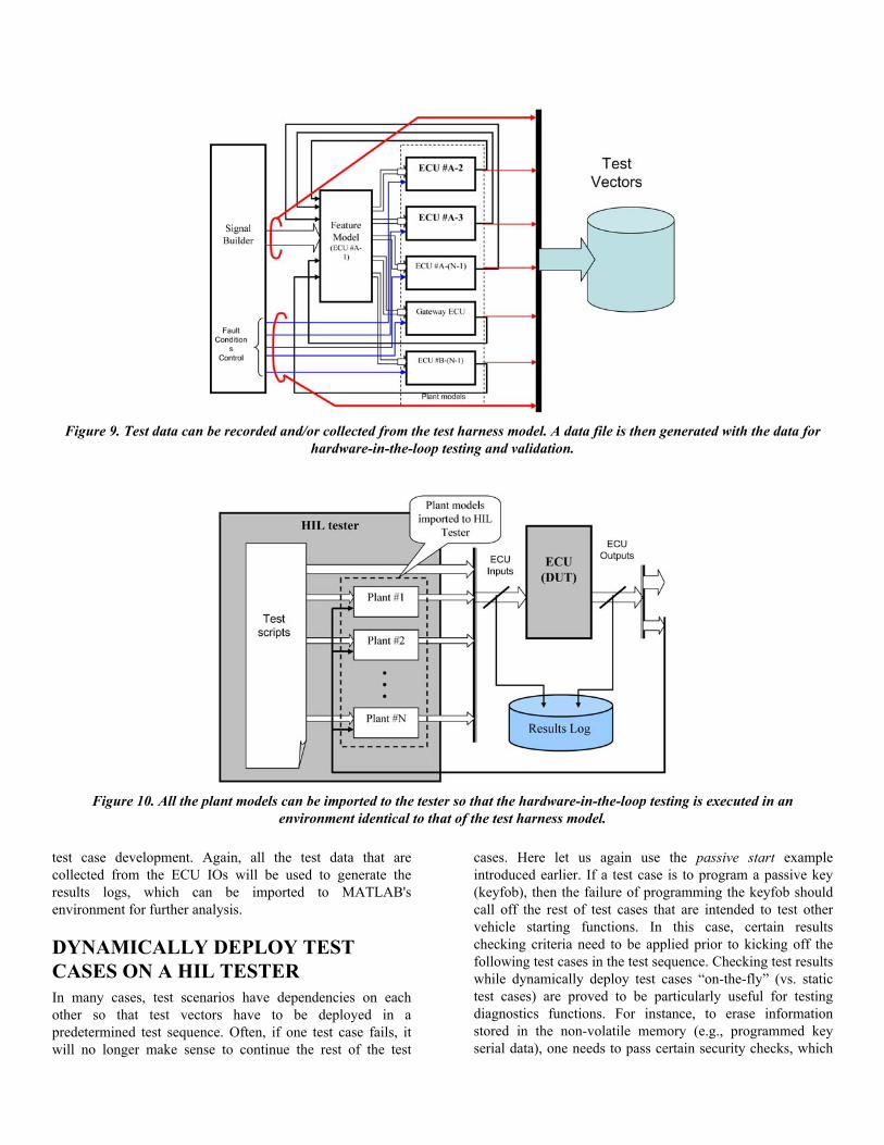
test case development. Again, all the test data that arecollected from the ECU IOs will be used to generate theresults logs, which can be imported to MATLAB'senvironment for further analysis.
DYNAMICALLY DEPLOY TESTCASES ON A HIL TESTERIn many cases, test scenarios have dependencies on eachother so that test vectors have to be deployed in apredetermined test sequence. Often, if one test case fails, itwill no longer make sense to continue the rest of the test
cases. Here let us again use the passive start exampleintroduced earlier. If a test case is to program a passive key(keyfob), then the failure of programming the keyfob shouldcall off the rest of test cases that are intended to test othervehicle starting functions. In this case, certain resultschecking criteria need to be applied prior to kicking off thefollowing test cases in the test sequence. Checking test resultswhile dynamically deploy test cases “on-the-fly” (vs. statictest cases) are proved to be particularly useful for testingdiagnostics functions. For instance, to erase informationstored in the non-volatile memory (e.g., programmed keyserial data), one needs to pass certain security checks, which
Figure 9. Test data can be recorded and/or collected from the test harness model. A data file is then generated with the data forhardware-in-the-loop testing and validation.
Figure 10. All the plant models can be imported to the tester so that the hardware-in-the-loop testing is executed in anenvironment identical to that of the test harness model.
normally involves multiple rounds of seed generation and keysubmittal. As the seed data will be randomly generated andthe key data will be calculated from the seed data, there is noway of using preset test vectors (i.e., static test cases) toaccomplish this task.
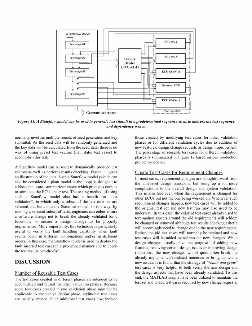
A Stateflow model can be used to dynamically produce testvectors as well as perform results checking. Figure 11 givesan illustration of the idea. Such a Stateflow model (which canalso be considered a plant model in-the-loop) is designed toaddress the issues summarized above which produces outputsto stimulate the ECU under test. The testing method of usingsuch a Stateflow model also has a benefit for “fastvalidation”, in which only a subset of the test case set areselected and built into the Stateflow model. In this way, byrunning a selected subset of tests, engineers can either ensurea software change not to break the already validated basicfunctions, or ensure a design change to be properlyimplemented. More importantly, this technique is particularlyuseful to verify the fault handling capability when faultevents occur in different combinations and/or in differentorders. In this case, the Stateflow model is used to deploy thefault inserted test cases in a predefined manner and to checkthe test results “on-the-fly”.
DISCUSSION
Number of Reusable Test CasesThe test cases created in different phases are intended to beaccumulated and reused for other validation phases. Becausesome test cases created in one validation phase may not beapplicable to another validation phase, additional test casesare usually created. Such additional test cases also include
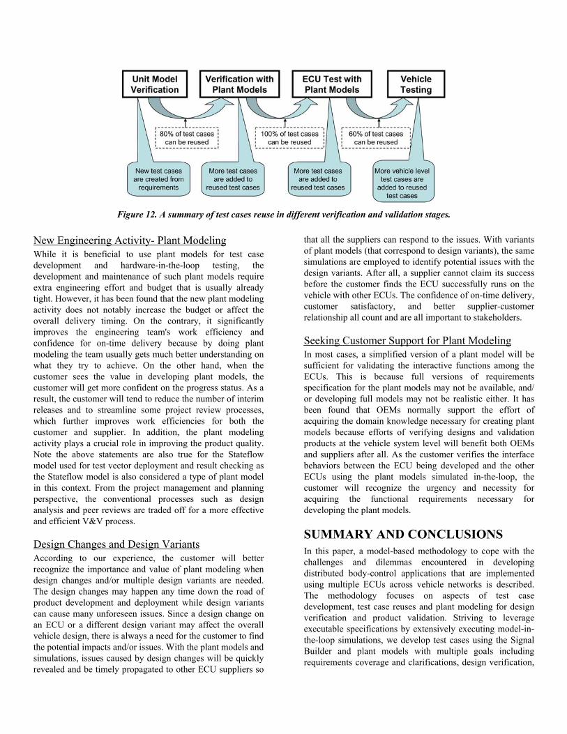
those created by modifying test cases for other validationphases or for different validation cycles due to addition ofnew features, design change requests or design improvement.The percentage of reusable test cases for different validationphases is summarized in Figure 12 based on our productionproject experience.
Create Test Cases for Requirement ChangesIn most cases, requirement changes are straightforward fromthe unit-level design standpoint but bring up a lot morecomplications to the overall design and system validation.This is also true even when the requirement is changed forother ECUs but not the one being worked on. Whenever suchrequirement changes happen, new test cases will be added tothe original test set and new test run may also need to beunderway. In this case, the existent test cases already used totest against aspects around the old requirements will seldombe changed or removed although test results checking criteriawill accordingly need to change due to the new requirements.Rather, the old test cases will normally be retained and newtest cases will be added to address the new changes. Whiledesign changes usually have the purposes of adding newfeatures, resolving certain design issues or improving designrobustness, the new changes would quite often break thealready implemented/validated functions or bring up wholenew issues. It is found that the strategy of “retain and grow”test cases is very helpful to both verify the new design andthe design aspects that have been already validated. To thisend, the MATLAB scripts have been utilized to maintain thetest set and to add test cases required by new change requests.
Figure 11. A Stateflow model can be used to generate test stimuli in a predetermined sequence so as to address the test sequenceand dependency issues.
New Engineering Activity- Plant ModelingWhile it is beneficial to use plant models for test casedevelopment and hardware-in-the-loop testing, thedevelopment and maintenance of such plant models requireextra engineering effort and budget that is usually alreadytight. However, it has been found that the new plant modelingactivity does not notably increase the budget or affect theoverall delivery timing. On the contrary, it significantlyimproves the engineering team's work efficiency andconfidence for on-time delivery because by doing plantmodeling the team usually gets much better understanding onwhat they try to achieve. On the other hand, when thecustomer sees the value in developing plant models, thecustomer will get more confident on the progress status. As aresult, the customer will tend to reduce the number of interimreleases and to streamline some project review processes,which further improves work efficiencies for both thecustomer and supplier. In addition, the plant modelingactivity plays a crucial role in improving the product quality.Note the above statements are also true for the Stateflowmodel used for test vector deployment and result checking asthe Stateflow model is also considered a type of plant modelin this context. From the project management and planningperspective, the conventional processes such as designanalysis and peer reviews are traded off for a more effectiveand efficient V&V process.
Design Changes and Design VariantsAccording to our experience, the customer will betterrecognize the importance and value of plant modeling whendesign changes and/or multiple design variants are needed.The design changes may happen any time down the road ofproduct development and deployment while design variantscan cause many unforeseen issues. Since a design change onan ECU or a different design variant may affect the overallvehicle design, there is always a need for the customer to findthe potential impacts and/or issues. With the plant models andsimulations, issues caused by design changes will be quicklyrevealed and be timely propagated to other ECU suppliers so
that all the suppliers can respond to the issues. With variantsof plant models (that correspond to design variants), the samesimulations are employed to identify potential issues with thedesign variants. After all, a supplier cannot claim its successbefore the customer finds the ECU successfully runs on thevehicle with other ECUs. The confidence of on-time delivery,customer satisfactory, and better supplier-customerrelationship all count and are all important to stakeholders.
Seeking Customer Support for Plant ModelingIn most cases, a simplified version of a plant model will besufficient for validating the interactive functions among theECUs. This is because full versions of requirementsspecification for the plant models may not be available, and/or developing full models may not be realistic either. It hasbeen found that OEMs normally support the effort ofacquiring the domain knowledge necessary for creating plantmodels because efforts of verifying designs and validationproducts at the vehicle system level will benefit both OEMsand suppliers after all. As the customer verifies the interfacebehaviors between the ECU being developed and the otherECUs using the plant models simulated in-the-loop, thecustomer will recognize the urgency and necessity foracquiring the functional requirements necessary fordeveloping the plant models.
SUMMARY AND CONCLUSIONSIn this paper, a model-based methodology to cope with thechallenges and dilemmas encountered in developingdistributed body-control applications that are implementedusing multiple ECUs across vehicle networks is described.The methodology focuses on aspects of test casedevelopment, test case reuses and plant modeling for designverification and product validation. Striving to leverageexecutable specifications by extensively executing model-in-the-loop simulations, we develop test cases using the SignalBuilder and plant models with multiple goals includingrequirements coverage and clarifications, design verification,
Figure 12. A summary of test cases reuse in different verification and validation stages.
hardware-in-the-loop validation, and reusing test casesthroughout the entire development process.
While the role of using plant models is emphasized, we alsostrive to reuse plant models in both virtual test harnessmodels and ECU hardware in-the-loop testing. The plantmodels may have broader implications in this context whichmay be behavioral models for other ECUs on the vehiclenetwork, models for fault insertions for both the ECU underdevelopment and its surrounding ECUs, and models that canissue diagnostic commands. If the feature models in the testharness model have been the core work for implementing theECU under development, then the development of plantmodels has become the focus for verifying and validating theECU. The models imported to the ECU tester can alsoinclude models for test results checking and verification.Moreover, some test vectors that have been designed in thetest harness model can be converted to Stateflow modelswhich can act as a dynamic input vector generator to the ECUunder test. Such test cases in the form of models have beenproved to be a very effective means to duplicate and identifyroot causes for software issues in the pre-production stage.The methodology is also very useful for a large scalemodeling project when multiple large models need to go intoone microcontroller.
The testing method introduced in this work is not intended toreplace the traditional integrated in-the-loop testing methods(such as a plywood buck testboard where all the ECUs areintegrated). Rather, the test method here provides analternative that facilitates fault insertion testing, automatictesting, and reusing test cases created in a virtual model-based testing environment. The future work may includemore study on plant modeling, including methods ofsimplifying plant models, maintaining changes for plantmodels, and strategically getting OEMs involved in theprocess so that MATLAB models with interactive functionscan be shared among suppliers.
REFERENCES1. Amsler, K.-J. Dr., Fetzer, Joachim Dr., Lederer, D. Dr.,Wernicke, M., “Virtual Design of Automotive ElectronicNetworks - From Function to ECU Software”, AutomotiveElectronics I/2004, special issue of ATZ, MTZ andAutomotive Engineering Partners, Vieweg Verlag(Wiesbaden, Germany), p. 2-4.
2. Navet, N., Monot, A., Bavoux, B., Simonot-Lion, F.,“Multi-source and multicore automotive ECUs - OSprotection mechanisms and scheduling”, Invited paper at theIEEE International Symposium on Industrial Electronics (ISI2010), Bari, Italy, July 4-7, 2010.
3. Fürst, Simon, “Challenges in the Design of AutomotiveSoftware”, BMW Group, 80788 Munich, Germany, 2010EDAA.
4. Hegde, Rajeshwari, Gurumurthy, K S, “Model BasedApproach for the Integration of ECUs”, Proceedings of theWorld Congress on Engineering 2008 Vol I, WCE 2008, July2 - 4, 2008, London, U.K.
5. Dillaber, E., Kendrick, L., Jin, W., and Reddy, V.,“Pragmatic Strategies for Adopting Model-Based Design forEmbedded Applications,” SAE Technical Paper2010-01-0935, 2010, doi:10.4271/2010-01-0935.
6. SAKAI, Kunihiro, NISSATO, Yukihiro, and KANEDA,Masahiro, “Comprehensive ECU Testing Using SimulationTools”, Mitsubishi Motors, Technical Review, 2007 No. 19.
7. Mitchell, B., “Characterizing Communication ChannelDeadlocks in Sequence Diagrams”, IEEE Transactions onSoftware Engineering, 2008, 34 (3). pp. 305-320.
8. Williams, B. C., “Model-Based Programming ofIntelligent Embedded Systems and Robotic Space Experts”,Proceedings of IEEE, Vol. 91, No. 1, January 2003.
9. Yang, J., Bauman, J., and Beydoun, A., “An EffectiveModel-Based Development Process Using Simulink/Stateflow for Automotive Body Control Electronics,” SAETechnical Paper 2006-01-3501, 2006, doi:10.4271/2006-01-3501.
10. Yang, J., Bauman, J., and Beydoun, A., “RequirementAnalysis and Development using MATLAB Models,” SAEInt. J. Passeng. Cars - Electron. Elect. Syst. 2(1):430-437,2009, doi:10.4271/2009-01-1548.
11. Lee, Edward A.: “Embedded Software”, Advances inComputers 56: 56-97 (2002).
12. Bauman, Jason G., LaZar, Darryn, “Lear ReducesEmbedded Software Issues Using the NI HIL Platform”,http://sine.ni.com/cs/app/doc/p/id/cs-12710 Accessed06/14/2010.
CONTACT INFORMATIONJinming [email protected]
Jason [email protected]
DEFINITIONS/ABBREVIATIONSECU
Electronic Control Unit
BCMBody-Control Module
PEPSPassive Entry and Passive Start
IO & IOsInput(s) and Output(s)
HILHardware-in-the-loop
IP & IPsIntellectual property/properties
V&VVerification and validation
MATLAB®A modeling environment from The MathWorksconsisting of a suite of software.
Simulink®/Stateflow®The modeling tools in the MATLAB® tool suite.
Signal BuilderA functional block from Simulink® library browser.
The Engineering Meetings Board has approved this paper for publication. It hassuccessfully completed SAE's peer review process under the supervision of the sessionorganizer. This process requires a minimum of three (3) reviews by industry experts.
All rights reserved. No part of this publication may be reproduced, stored in aretrieval system, or transmitted, in any form or by any means, electronic, mechanical,photocopying, recording, or otherwise, without the prior written permission of SAE.
ISSN 0148-7191
doi:10.4271/2010-01-2328
Positions and opinions advanced in this paper are those of the author(s) and notnecessarily those of SAE. The author is solely responsible for the content of the paper.
SAE Customer Service:Tel: 877-606-7323 (inside USA and Canada)Tel: 724-776-4970 (outside USA)Fax: 724-776-0790Email: [email protected] Web Address: http://www.sae.orgPrinted in USA