Distributed Architecture for Intelligent Robotic Assembly
38
401 14 Distributed Architecture for Intelligent Robotic Assembly Part III: Design of the Invariant Object Recognition System Mario Pena-Cabrera and Ismael Lopez-Juarez 1. Introduction In previous chapter it has been described the overall architecture for multimo- dal learning in the robotic assembly domain (Lopez-Juarez & Rios Cabrera, 2006). The acquisition of assembly skills by robots is greatly supported by the effective use of contact force sensing and object recognition. In this chapter we will describe the robot’s ability to invariantly recognise assembly parts at dif- ferent scale, rotation and orientation within the work space. The chapter shows a methodology for on-line recognition and classification of pieces in robotic as- sembly tasks and its application into an intelligent manufacturing cell. The performance of industrial robots working in unstructured environments can be improved using visual perception and learning techniques. In this sense, the described technique for object recognition is accomplished using an Artifi- cial Neural Network (ANN) architecture which receives a descriptive vector called CFD&POSE as the input. This vector represents an innovative method- ology for classification and identification of pieces in robotic tasks, every stage of the methodology is described and the proposed algorithms explained. The vector compresses 3D object data from assembly parts and it is invariant to scale, rotation and orientation, and it also supports a wide range of illumina- tion levels. The approach in combination with the fast learning capability of ART networks indicates the suitability for industrial robot applications as it is demonstrated through experimental results. Robotics field has grown considerably with new technologies, industrial ro- bots today, needs sensorial capabilities to achieve non-structured and more sophisticated tasks; vision systems as a sensorial mode for robots have a grow- ing demand requiring more complex and faster image processing functions in order to implement more sophisticated industrial applications, like assembly automation. Source: Manufacturing the Future, Concepts - Technologies - Visions , ISBN 3-86611-198-3, pp. 908, ARS/plV, Germany, July 2006, Edited by: Kordic, V.; Lazinica, A. & Merdan, M. Open Access Database www.i-techonline.com
Transcript of Distributed Architecture for Intelligent Robotic Assembly

401
14
Distributed Architecture for Intelligent Robotic Assembly
Part III:
Design of the Invariant Object Recognition System
Mario Pena-Cabrera and Ismael Lopez-Juarez
1. Introduction
In previous chapter it has been described the overall architecture for multimo-
dal learning in the robotic assembly domain (Lopez-Juarez & Rios Cabrera,
2006). The acquisition of assembly skills by robots is greatly supported by the
effective use of contact force sensing and object recognition. In this chapter we
will describe the robot’s ability to invariantly recognise assembly parts at dif-
ferent scale, rotation and orientation within the work space. The chapter shows
a methodology for on-line recognition and classification of pieces in robotic as-
sembly tasks and its application into an intelligent manufacturing cell. The
performance of industrial robots working in unstructured environments can
be improved using visual perception and learning techniques. In this sense,
the described technique for object recognition is accomplished using an Artifi-
cial Neural Network (ANN) architecture which receives a descriptive vector
called CFD&POSE as the input. This vector represents an innovative method-
ology for classification and identification of pieces in robotic tasks, every stage
of the methodology is described and the proposed algorithms explained. The
vector compresses 3D object data from assembly parts and it is invariant to
scale, rotation and orientation, and it also supports a wide range of illumina-
tion levels. The approach in combination with the fast learning capability of
ART networks indicates the suitability for industrial robot applications as it is
demonstrated through experimental results.
Robotics field has grown considerably with new technologies, industrial ro-
bots today, needs sensorial capabilities to achieve non-structured and more
sophisticated tasks; vision systems as a sensorial mode for robots have a grow-
ing demand requiring more complex and faster image processing functions in
order to implement more sophisticated industrial applications, like assembly
automation.
Source: Manufacturing the Future, Concepts - Technologies - Visions , ISBN 3-86611-198-3, pp. 908, ARS/plV, Germany, July 2006, Edited by: Kordic, V.; Lazinica, A. & Merdan, M.
Ope
n A
cces
s D
atab
ase
ww
w.i-
tech
onlin
e.co
m

Manufacturing the Future: Concepts, Technologies & Visions 402
In this sense, vision recognition systems must be capable of perceiving and de-
tecting images and objects, as close as the human vision does; this fact has en-
couraged research activity to design artificial vision systems based on the neu-
ral morphology of the biological human vision system. Now scientists
understand better about how computational neural structures and artificial vi-
sion systems must be designed following neural paradigms, mathematical
models and computational architectures. When a system involves these as-
pects, it can be referred to as a “Neuro-Vision System” (Gupta and Knopf,
1993), (Peña, 2004), which can be defined as an artificial machine with ability
to see our environment and provide visual formatted information for real time
applications.
It has been shown by psychological and clinical studies that visual object rec-
ognition involves a large activity area on the cerebral cortex when objects are
seen the first time and the region’s activity is reduced when familiar objects are
perceived (Gupta and Knopf, 1993). New objects can also be learned quickly if
certain clues are given to the learner. Following this psychological evidence a
novel architecture was designed. The architecture is firstly trained with clues
representing different objects that the robot is likely to encounter within the
working space to form its initial knowledge base. This information then trig-
gers the on-line learning subsystem based on an Artificial Neural Network
(ANN), the new image vector descriptors override initial clues, and the robot
learns to identify familiar objects and to learn new ones.
The above ideas suggested that it was possible to get fast and reliable informa-
tion from a simple but focused analysis of what an object might show. The
very important aspects of the scene (we have called “clues”), can be used later
to retrieve memorized aspects of the object without having to recall detailed
features. By using neural networks it is possible to learn manipulative skills
which can be used by an industrial manipulator (Lopez-Juarez and M. How-
arth, 2000). In someway we humans do that process once an object has been
seen and learned for the first time.
The chapter describes a methodology for on-line object recognition, based on
artificial neural networks for identification and classification purposes. Robust
algorithms for perimeter, centroid calculations, object functions and pose esti-
mation are presented.

Distributed Architecture for Intelligent Robotic Assembly, Part III: Design… 403
2. Related work
Intelligent manufacturing cells using robots with sensorial capabilities are be-
ing investigated using Artificial Intelligence techniques like ANN’s and Fuzzy
Logic among others, since mathematical and control models are simplified.
Acquiring information from multiple sensors in manufacturing systems pro-
vides robustness and self-adaptation capabilities, hence improving the per-
formance in industrial robot applications. A few researchers have applied neu-
ral networks to assembly operations with manipulators and force feedback.
(Vijaykumar Gullapalli, 1994), used BackPropagation (BP) and Reinforcement
Learning(RL) to control a Zebra robot, its neural controller was based on the
location error reduction beginning from a known location, (Enric Cervera,
1997), employed Self-Organization Map (SOM) and RL to control a Zebra ro-
bot, the location of the destination piece was unknown, (Martin Howarth,
1998), utilized BP and RL to control a SCARA robot, without knowing the loca-
tion of assembly, (Lopez-Juarez, 2000), implemented FuzzyARTMAP to con-
trol a PUMA robot also with an unknown location. All of the above authors
considered only constraint motion control during assembly; however, to com-
plete the autonomy of the assembly system a machine vision system has also
to be considered. Additionally, a new concept was introduced in 1988 called
“Robotic Fixtureless Assembly” (RFA) (Hoska, 1998), that eliminates the need
of using complex and rigid fixtures, which involves new technical challenges,
but allows very potential solutions. Studies of RFA of flexible parts with a dy-
namic model of two robots which does not require measurements of the part
deflections have been done (W. Ngyuen and J.K. Mills, 1996). (Plut, 1996), and
(Bone, 1997), presented a grasp planning strategy for RFA. The goal of RFA is
to replace these fixtures with sensor-guided robots which can work within
RFA workcells. The development of such vision-guided robots equipped with
programmable grippers might permit holding a wide range of part shapes
without tool changing. Using Artificial Neural Networks, an integrated intelli-
gent vision-guided system can be achieved as it is shown by (Langley et al.,
2003). This job can be achieved by using 2D computer vision in different man-
ner so that 3D invariant object recognition and POSE calculation might be used
for aligning parts in assembly tasks if an –“adequate descriptor vector”- is
used and interfaced in real time to a robot. Many authors had come with de-
scriptor vectors and image transformations, used as general methods for com-
puter vision applications in order to extract invariant features from shapes.

Manufacturing the Future: Concepts, Technologies & Visions 404
(Alberto S. Aguado et al., 2002), developed a new formulation and methodol-
ogy for including invariance in general form of the Hough transform, (Chin-
Hsiung et al., 2001), designed a technique for computing shape moments
based on the quadtree representation of images, (P. J. Best and N. McKay,
1992), describe a method for registration of 3D shapes in minutes, (A. Torralba
and A. Oliva, 2002), present a method to infer the scale of the scene by recog-
nizing properties of the scene structure for depth estimation, (Freeman, 1961),
introduced the first approach for representing digital curves using chain codes,
and showing classical methods for processing chains (Freeman, 1974), (E.
Bribiesca, 1999), developed a new chain code for shapes composed of regular
cells, which has recently evolved even to represent 3D paths and knots.
Some authors use multiple cameras or multiple views to extract information,
performs invariant object recognition and determine object’s position and mo-
tion, (Stephen A. Underwood, 1975), developed a visual learning system using
multiple views which requires deterministic description of the object’s surfaces
like measurements and interconnections, (Yong-Sheng Chen et al., 2001), pro-
pose a method to estimate the three dimensional ego-motion of an observer
moving in a static environment, (Hiroshi Murase and Shree K. Nayar, 1995),
have worked in visual learning and recognition of 3D objects from appearance,
(E. Gonzalez-Galvan et al., 1997), developed a procedure for precision measure
in 3D rigid-body positioning using camera-space manipulation for assembly.
(Dickmanns, 1998), and (Nagel, 1997), have shown solutions to facilitate the
use of vision for real world-interaction, (Hager et al., 1995), and (Papaniko-
lopoulos et al., 1993), use markers on the object to simplify detection and track-
ing of cues.
Some other authors have contributed with techniques for invariant pattern
classification, like classical methods as the universal axis of Lin, and invariant
moments of (Hu, 1962), or artificial intelligence techniques, as used by (Cem
Yüceer and Kemal Oflazer, 1993), which describes an hybrid pattern classifica-
tion system based on a pattern pre-processor and an ANN invariant to rota-
tion, scaling and translation, (Stavros J. and Paulo Lisboa, 1992), developed a
method to reduce and control the number of weights of a third order network
using moment classifiers and (Shingchern D. You and G. Ford, 1994), proposed
a network for invariant object recognition of objects in binary images. Applica-
tions of guided vision used for assembly are well illustrated by (Gary M. Bone
and David Capson, 2003), which developed a vision-guide fixtureless assem-
bly system using a 2D computer vision for robust grasping and a 3D computer

Distributed Architecture for Intelligent Robotic Assembly, Part III: Design… 405
vision to align parts prior to mating, and (Stefan Jörg et al., 2000), designing a
flexible robot-assembly system using a multi-sensory approach and force
feedback in the assembly of moving components.
3. Invariant Object Recognition
Recognising an object using a vision system involves a lot of calculations and
mathematical processes which have to be implemented and tested in order to
be used in a real application. In this way, vision systems and solid state tech-
nologies has been evolved at the same time, the more faster and sophisticated
computers had come with the more complex and better vision systems devel-
oped as well as more sophisticated algorithms implementation had became a
reality.
Basic ideas were established with approximated representations, architectures
and algorithms, which motivated the development of this research area. A
general solution to the recognition problem does not exist (J. L. Mundy, 1998).
Most classical methods to object recognition use shape analysis and metric fea-
ture extraction from digitized images to reach the goal. Recent research, points
to use artificial intelligence techniques to look for invariant recognition solu-
tions using vision. In this way artificial neural networks are a well representa-
tive technique to this purpose
3.1 Learning
For a better understanding of the recognition problem, it is convenient to ex-
plore how humans make the recognition process, sometimes in an automatic
manner and many times in short periods of time, as it is the case of a projected
image in the retina which can be rotated, moved or even scaled when the ob-
ject or eyes are moved. Humans can recognize an object within a complex
scene with overlapped objects.
Most recognition techniques uses indirect mapping between objects and retinal
images, there is a set of object representations in long term memory which
have been associated with object physical representations, and information is
not just a copy of a pattern of retinal stimulus but a set of features representa-
tive of the object with invariant properties, so the object can be recognized
from different views. There must be a criteria to decide which is the best object
representation within the long term memory when an input object representa-

Manufacturing the Future: Concepts, Technologies & Visions 406
tion is not exactly the same to the one already memorized. It is difficult to
know when the perception process ends and when the recognition process be-
gins.
Human visual process can execute a universal set of routines with simple sub-
processes operating with object sketches even in 2 ½ dimensions (S. Ulman,
1984), this activities might involve: contour scanning, region filling and area
marking to obtain as the output, basic features from the most important issues
of a visual scene as shapes and its spatial relation, this goes to the process of
object recognition by way of its parts grouping reconstruction, because objects
can be overlapped or occluded. Assuming that memorized parts corresponds
to previous visual learning processes, a shape can be addressed and recon-
structed with a huge part list, so recognition can be achieved using only the
visible parts within the scene.
3.2 Memory and Recall
There are at least two different processes to storage information in the long
term memory. The first process is to store a list of situations about the objects
including information on how many parts are grouped together, its size, cate-
gory names and so on. The other process is to store the codification of object
appearance. There is evidence that the time a person takes to decide if two 3D
objects have the same shape is a linear function of its orientation difference
(R.N. Shepard and S. Hurwitz, 1984). This information might be understood as
the humans falls in a continuous and smooth rotation mental process which is
achieved until the orientation input shape, matches the correct canonical orien-
tation of shape already stored.
A person cannot see an object in a single view from an arbitrary view angle, in
fact, first the object is visualized with a canonic orientation to be rotated to the
specific orientation, this suggests the idea that long term memory image repre-
sentations are oriented to a primitive and primary observation stored as ca-
nonical shapes, which is an important point to our research inspiration.
3.3 Design considerations and techniques
In order to design and implement a vision system and use the appropriate
techniques in the visual process, three aspects might be considered:
Distributed Architecture for Intelligent Robotic Assembly, Part III: Design… 407
• Vision is a computational process
• Obtained description of object is a function of the observer
• Not used information within the scene has to be eliminated
Because vision is a complex process different vision levels are established for
better methodology directions:
• Low level processing.- pixel direct working is done in this level to
extract properties as: edges, gradients, textures, grey levels, etc.
• Medium level processing.- elements of low level are grouped here to
obtain lines, regions of interest in order to use segmentation tech
niques.
• High level processing.- it is oriented to interpretation of lower levels
Information using models and previous knowledge. It has to deal
with recognition and looks for consistency on feature primitive in
formation interpretation.
Representation is a formal system to specify features of what is seen with a vi-
sion system, two aspects are important:
a) the model representation, is the structure used to model the representation
b) the recognition process is the way the model and representation are used
for recognition.
These aspects have to be generic, time and space efficient, rotation, translation
and scaled invariant, and conform robustness and noise and incomplete in-
formation tolerance. High level vision systems can be classified in:
• Model based vision systems.- use a geometrical representation and
recognition is based on correspondence.
• Knowledge based vision systems.- use a symbolic representation
and recognition is based on inferences.
Model based vision systems use predefined geometrical methods to recognize the
objects whose description has been obtained from images, its principal com-
ponents are: feature extraction, modelling, and matching and can use 2D or 3D

Manufacturing the Future: Concepts, Technologies & Visions 408
models. Because of its robustness and fast processing, manufacturing applica-
tions mostly use binary images, becoming the quantization process an impor-
tant factor because all parametric calculations and description are derived
from it. Shape based human recognition takes the information about perimeter
as fundamental instead of regions, most 2D models used in real implementa-
tions are model and recognition object oriented as a function of its image rep-
resentation as a 2D matrix array.
Knowledge based vision systems use proposal models for representation; they
have a collection set of them representing knowledge about objects and their
relationship. Recognition is achieved by way of inferences, from image data
and domain knowledge, object identity is obtained, its principal components
are:
a) feature extraction, important attributes of the image are obtained to be in-
tegrated in a symbolic image
b) knowledge representation, is constructed with a learning process being
stored in the primitive knowledge data base
c) inference, a deductive process is achieved from the symbolic image and
primitive knowledge data base to get the object identity and location.
4. Visual behaviour
The problems of modelling and understanding visual behaviour and their se-
mantics are often regarded as computationally ill-defined. Cognitive under-
standing cannot adequately explain why we associate particular meanings
with observed behaviours. Interpretation of visual behaviour can rely on sim-
ple mappings from recognized patterns of motion to semantics, but human ac-
tivity is complex, the same behaviour may have several different meanings
depending upon the scene and task context. Behaviour interpretation often
also requires real-time performance if it is to be correct in the relevant dynamic
context, by real time, it is not necessary implied that all computation must be
performed at full video frame-rate, as long as the interpretation of behaviour
proceeds within some required time constraint, (Shaogang et. al., 2002).
Considering that it is estimated that 60% of sensory information in humans is
provided by the visual pathway (Kronauer, 1985), and the biological vision
Distributed Architecture for Intelligent Robotic Assembly, Part III: Design… 409
concerning the pathway is a massively parallel architecture using basic hierar-
chical information processing (Uhr, 1980), it seems logical to look for an alter-
native approach with less computational power to better emulate the human
visual system and it is given by connectionist models of the human cognitive
process, such idea has to be considered to develop machine vision system ap-
plications today, as robotic assembly vision guided manufacturing processes.
4.1 Inspiring Ideas
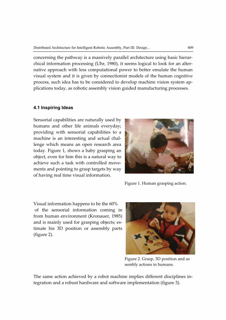
Sensorial capabilities are naturally used by
humans and other life animals everyday;
providing with sensorial capabilities to a
machine is an interesting and actual chal-
lenge which means an open research area
today. Figure 1, shows a baby grasping an
object, even for him this is a natural way to
achieve such a task with controlled move-
ments and pointing to grasp targets by way
of having real time visual information.
Figure 1. Human grasping action.
Visual information happens to be the 60%
of the sensorial information coming in
from human environment (Kronauer, 1985)
and is mainly used for grasping objects; es-
timate his 3D position or assembly parts
(figure 2).
Figure 2. Grasp, 3D position and as
sembly actions in humans.
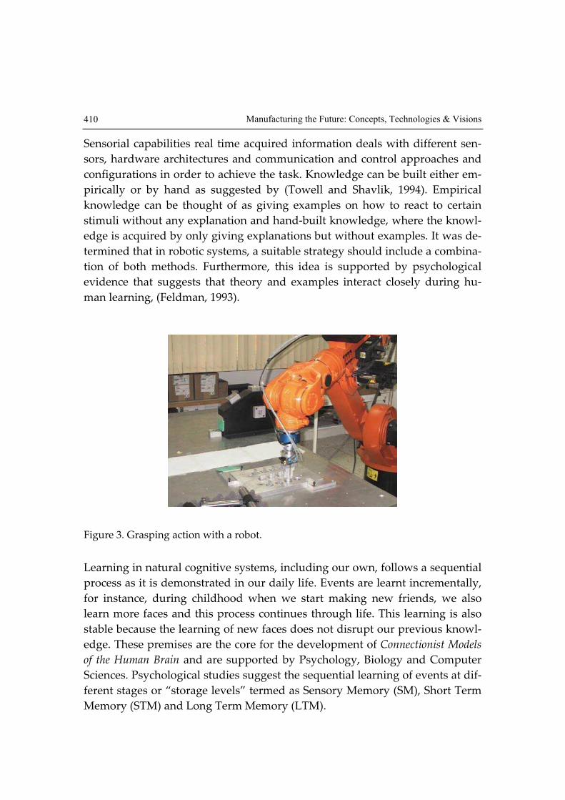
The same action achieved by a robot machine implies different disciplines in-
tegration and a robust hardware and software implementation (figure 3).
Manufacturing the Future: Concepts, Technologies & Visions 410
Sensorial capabilities real time acquired information deals with different sen-
sors, hardware architectures and communication and control approaches and
configurations in order to achieve the task. Knowledge can be built either em-
pirically or by hand as suggested by (Towell and Shavlik, 1994). Empirical
knowledge can be thought of as giving examples on how to react to certain
stimuli without any explanation and hand-built knowledge, where the knowl-
edge is acquired by only giving explanations but without examples. It was de-
termined that in robotic systems, a suitable strategy should include a combina-
tion of both methods. Furthermore, this idea is supported by psychological
evidence that suggests that theory and examples interact closely during hu-
man learning, (Feldman, 1993).
Figure 3. Grasping action with a robot.
Learning in natural cognitive systems, including our own, follows a sequential
process as it is demonstrated in our daily life. Events are learnt incrementally,
for instance, during childhood when we start making new friends, we also
learn more faces and this process continues through life. This learning is also
stable because the learning of new faces does not disrupt our previous knowl-
edge. These premises are the core for the development of Connectionist Models
of the Human Brain and are supported by Psychology, Biology and Computer
Sciences. Psychological studies suggest the sequential learning of events at dif-
ferent stages or “storage levels” termed as Sensory Memory (SM), Short Term
Memory (STM) and Long Term Memory (LTM).

Distributed Architecture for Intelligent Robotic Assembly, Part III: Design… 411
4.2 Artificial Neural Networks
There are different types of ANN, for this research a Fuzzy ARTMAP network
is used, ART stands for Adaptive Resonance Theory, which is a well estab-
lished associative brain and competitive model introduced as a theory of the
human cognitive processing developed by Stephen Grossberg at Boston Uni-
versity. Grossberg resumed the situations mentioned above in what he called
the Stability-Plasticity Dilemma suggesting that connectionist models should be
able to adaptively switch between its plastic and stable modes. That is, a sys-
tem should exhibit plasticity to accommodate new information regarding un-
familiar events. But also, it should remain in a stable condition if familiar or ir-
relevant information is being presented. These features suggested the use of
this network because of its incremental knowledge capabilities and stability,
but mostly because of the fast recognition and clustering responses.
Grossberg identified the problem as due to basic properties of associative
learning and lateral inhibition. An analysis of this instability, together with
data of categorisation, conditioning, and attention led to the introduction of
the ART model that stabilises the memory of self-organising feature maps in
response to an arbitrary stream of input patterns (S. Grossberg, 1976). The core
principles of this theory and how Short Term Memory (STM) and Long Term
Memory (LTM) interact during network processes of activation, associative
learning and recall were published in the scientific literature back in the 60's.
The theory has evolved in a series of real-time architectures for unsupervised
learning, the ART-1 algorithm for binary input patterns (G. Carpenter, 1987),
supervised learning is also possible through ARTMAP (G. Carpenter, 1991),
that uses two ART-1 modules that can be trained to learn the correspondence
between input patterns and desired output classes. Different model variations
have been developed to date based on the original ART-1 algorithm, ART-2,
ART-2a, ART-3, Gaussian ART, EMAP, ViewNET, Fusion ARTMAP,
LaminART just to mention but a few.
5. Manufacturing
5.1 Intelligent manufacturing systems
Different sensors have been used in manufacturing systems to achieve specific
tasks such as robot guiding, soldering, sorting, quality control and inspection.
Manufacturing the Future: Concepts, Technologies & Visions 412
Integration of new architectures and methods using sensorial modalities in
manufacturing cells like vision, force-sensing and voice recognition becomes
an open research field today.
Most automated systems integrators and designers had pushed hard to get
faster and more accurate industrial robot systems but sensorial capabilities
have not been developed completely to provide the required flexibility and
autonomy for manufacturing tasks.
Basic requirements within an industrial production environment have to be
satisfied to guarantee an acceptable manufacturing process; some factors are
the tool or work-piece position uncertainty, which is achieved by using expen-
sive structured manufacturing cells. Other factors are the force-torque and in-
teraction evaluation with the task environment. By using self-adaptive robots
with sensorial capabilities and skill learning on-line, great flexibility and
adaptability is given to manufactured processes, so the idea of giving ma-
chines capabilities like humans in learning and execution tasks becomes real,
(L.Wu, 1996).
These ideas points to use in manufacturing applications today, what is called
Intelligent Manufacturing Systems, and can be thought as a high technology set
of tool devices arranged within a working close ambient called manufacturing
cell, and having an efficient collective team work, to achieve an autonomous
manufacturing process with on line reprogramming facilities and having a
manufactured product as it output. Such an intelligent system then, becomes a
self-adapting and self-learning system (figure 4).
5.2. Assembly
The success of assembly operations using industrial robots is currently based
on the accuracy of the robot itself and the precise knowledge of the environ-
ment, i.e., information about the geometry of the assembly parts and their lo-
calisation in the workspace. Robot manipulators operate in real world situa-
tions with a high degree of uncertainty and require sensing systems to
compensate from potential errors during operations. Uncertainties come from
a wide variety of sources such as robot positioning errors, gear backlash, arm
deflection, ageing of mechanisms and disturbances. Controlling all the above
aspects would certainly be a very difficult task; therefore a simpler approach is
preferred like using vision-guided robots for aligning parts in assembly tasks.

Distributed Architecture for Intelligent Robotic Assembly, Part III: Design… 413
Figure 4. Intelligent Manufacturing System
6. Vision system
Machine Vision systems are mainly used today in applications as inspection,
quality control and assembly tasks, they have been adopted now as a neces-
sary technology in modern automated industries based in functional parame-
ters and can be seen as a technology which is connecting cameras with com-
puters for real-time interpretation of industrial behaviour images to acquire
manufacturing applications. In this chapter a novel method to this purpose is
presented and several tests were carried out to assess a vision-guided assem-
bly process using aluminium pegs with different cross-sectional geometry,
they are named: circular, squared and radiused-square (termed radi-
used-square because it was a square peg with one corner rounded). These
components are shown in Figure 5 as well as the peg-in-hole operation in Fig-
ure 6. The diameter of the circular peg was 25 mm and the side of the square
peg was also 25 mm. The dimensions of the non-symmetric part, the radi-
used-square, was the same as the squared peg with one corner rounded to a
radius of 12.5 mm. Clearances between pegs and mating pairs were 0.1 mm,
chamfers were at 45 degrees with 5 mm width. The assembly was ended when
3/4 of the body of the peg were inside the hole. This represented 140 motion
steps in the -Z assembly direction.
Male
Component

Manufacturing the Future: Concepts, Technologies & Visions 414
Figure 5. Assembly Components
Figure 6. Peg-in-hole operation
In our experiments, the robot grasps pieces from a conveyor belt and performs
an assembly task using a force-sensing system described in (Corona-Castuera
& Lopez-Juarez, 2006), the vision system obtains an image to recognize and
calculates the object’s pose estimation and sends the information to the robot.
6.1 Vision workspace
The vision system was implemented with a high speed camera CCD/B&W,
PULNIX 6710, with 640x480 resolution and a PC dedicated computer, the
Radiused-Square Circular Square
15
25
1515
2512.5R 0
Units in mm

Distributed Architecture for Intelligent Robotic Assembly, Part III: Design… 415
camera movements above the X-Y plane was implemented with a computer
controlled 2D positioning electro-mechanical system (figure 7).
Figure 7. Vision workspace. Overview and 2D close up of positioning system
The vision system interaction schedule is working in a distributed systems as
described in (Lopez-Juarez & Rios-Cabrera, 2006) linked to a robotic assembly
module and a custom interface with a camera positioning system configured
as a monocular dynamic system.
Manufacturing the Future: Concepts, Technologies & Visions 416
The vision system can get visual information from the manufacturing system
workspace. To achieve an assembly task, the robotic assembly system sends
commands to the vision system as follows:
$SENDINF#1 Send Information of Zone 1:
zone 1 is the place where the robot grasps the male components. The robot can
locate different pieces and their characteristics.
$SENDINF#2 Send information of zone 2:
zone 2 is the place where the robot is performing the assembly task. The as-
sembly system can request information about the female component such as
position and shape.
$RESEND#X Resend information of zone X:
This command will be useful when the information received by the assembly
system coming from the vision system is incorrect, due to an error in the check
sum or any other error.
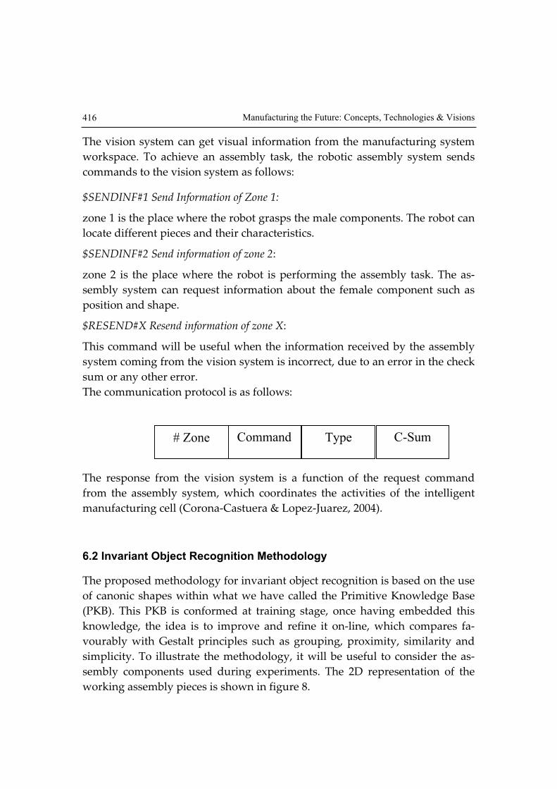
The communication protocol is as follows:
The response from the vision system is a function of the request command
from the assembly system, which coordinates the activities of the intelligent
manufacturing cell (Corona-Castuera & Lopez-Juarez, 2004).
6.2 Invariant Object Recognition Methodology
The proposed methodology for invariant object recognition is based on the use
of canonic shapes within what we have called the Primitive Knowledge Base
(PKB). This PKB is conformed at training stage, once having embedded this
knowledge, the idea is to improve and refine it on-line, which compares fa-
vourably with Gestalt principles such as grouping, proximity, similarity and
simplicity. To illustrate the methodology, it will be useful to consider the as-
sembly components used during experiments. The 2D representation of the
working assembly pieces is shown in figure 8.
Command# Zone Type C-Sum

Distributed Architecture for Intelligent Robotic Assembly, Part III: Design… 417
Figure 8. Assembly pieces
These canonical shapes serve as “clues” inserted initially in the PKB which ini-
tialise the grouping process (clustering). The knowledge is acquired by pre-
senting multiple instances of the object such as those shown in figure 9 where
an example of the circular shape and some of the possible views are illustrated.
The following step is to code the object’s information to get a descriptor vector,
so that its description be invariant to location, scaling and rotation, the algo-
rithm is explained in the following section.
Figure 9. Multiple instances of the circular shape.
Having such a descriptor vector, an ANN can be trained to conform the de-
scriptor vector families which can be generated on-line with the vision system.
Manufacturing the Future: Concepts, Technologies & Visions 418
6.3 Methodology
CFD&POSE methodology steps are:
• Fast acquisition of working visual scene
• Find the region of interest (ROI)
• Calculate the histogram of the image.
• Search for pieces
• Centroid calculation
• Piece orientation
• Calculate boundary object function (BOF)
• Descriptor vector generation and normalization (CFD&POSE).
• Information processing in the neural network
6.3.1 Fast acquisition of working visual scene
Image acquisition is carried out by the vision workspace configuration de-
scribed previously, comprised with a CCD/B&W digital camera, frame grabber
and custom visual C++ based software acquisition.
6.3.2 Finding the region of interest
It is desirable first to segment the region of the whole scene to have only the
workpieces Region of Interest (ROI). There are two defined regions of interest in
the manufacturing cell:
• the assembly workspace (zone 1)
• the identification/grasping workspace (zone 2).
The camera has to be positioned in the vision zone requested by the robot. The
2D positioning system, which uses feedback vision using a searching algo-
rithm, employs two LED’s within the scene as a calibration reference in order
to reach the exact position of the camera vision system (figure 10). The original
image is 480 x 640 pixels, 8-bit greyscale resolution. Image conditioning is car-
ried out avoiding the processing of small objects and finding the initial posi-
tion of the desired zone. The quantized grey level value of the LEDs in the im-
age, is greater than or equal to a specific gray level value GL regardless of the
amount of light in the zone. With this process, most of the objects that can con-
fuse the system are rejected. Then the ROI is first extracted by using the 2D
histogram information and initial position reference.

Distributed Architecture for Intelligent Robotic Assembly, Part III: Design… 419
Figure 10. Zone 1 vision workspace
To determine which are the more approximated white blobs within the image,
it has to be considered the mark using the following criteria:
• colour GL > 245
• 25 Perimeter 35 pixels (i.e., LED measured size)
• Distance between LED’s, must be constant (50 mm ± 3 mm).
In the initial position search, only the objects that fulfil all mentioned charac-
teristics are processed, all others are rejected. In this way, initial position is
found and ROI is defined as it is shown in figure 10.
6.3.3 Image histogram process
An algorithm using 1D and 2D image histograms is used in order to provide
the system of illumination invariance within some specific range. From these
histograms, threshold values are used for image segmentation of the back-
ground and the pieces within the ROI eliminating the noise that may appear.
This dynamic threshold value calculation allows independent light conditions
operation of the system. The 1D histogram normally has the aspect shown in
figure 11.

Manufacturing the Future: Concepts, Technologies & Visions 420
The 2 peaks in the histogram represent the background and the pieces in the
image. After the histogram calculation, an image binarization is performed us-
ing a threshold operator.
0
1000
2000
3000
4000
5000
6000
7000
1 14 27 40 53 66 79 92 105 118 131 144 157 170 183 196 209 222 235 248
Serie1
Figure 11. Histogram of the region of interest (ROI).
6.3.4 Search for pieces
For searching purposes, the system calculates the perimeter obtaining:
• number of points around a piece
• group of points coordinates X&Y, corresponding to the perimeter of the
piece measured clockwise
• boundaries of the piece 2D Bounding Box (2D-BB)
The perimeter calculation for every piece in the ROI is performed after the bi-
narization. Search is always accomplished from left to right and from top to
bottom. Once a white pixel is found, all the perimeter is calculated with a
search function (figure 12).
Background
Assembly pieces

Distributed Architecture for Intelligent Robotic Assembly, Part III: Design… 421
Figure 12. Perimeter calculation of a workpiece
The next definitions are useful to understand the algorithm:
• A nearer pixel to the boundary is any pixel surrounded mostly by black
pixels in connectivity eight.
• A farther pixel to the boundary is any pixel that is not surrounded by black
pixels in connectivity eight.
• The highest and lowest coordinates are the ones that create a rectangle
(Boundary Box).
The search algorithm executes the following procedures once it has found a
white pixel:
1. Searches for the nearer pixel to the boundary that has not been already lo-
cated.
2. Assigns the label of actual pixel to the nearer pixel to the boundary re-
cently found.
3. Paints the last pixel as a visited pixel.
4. If the new coordinates are higher than the last higher coordinates, it is as-
signed the new values to the higher coordinates.
5. If the new coordinates are lower than the last lower coordinates, it is as-
signed the new values to the lower coordinates.
6. Steps 1 to 5 are repeated until the procedure begins to the initial point, or
no other nearer pixel to the boundary is found.
Manufacturing the Future: Concepts, Technologies & Visions 422
This technique will surround any irregular shape, and will not process useless
pixels of the image, therefore this is a fast algorithm that can perform online
classification, and can be classified as linear:
O (N * 8*4)
where N is the size of the perimeter, and 8 & 4 are the number of comparisons
the algorithm needs to find the pixel farer to the boundary, the main difference
with the traditional algorithm consist of making the sweep in an uncertain
area which is always larger than the figure, this turns the algorithm into:
O(N*M)
N*M, is the size of the Boundary Box in use, and it does not obtain the coordi-
nates of the perimeter in the desired order.
6.3.5 Centroid calculation
The proposed procedure for centroid calculation is performed at the same time
that the coordinates of the perimeter are calculated without using the N*M
pixels box, (Boundary Box).
The coordinates of the centroid (Xc, Yc) are calculated with the following pro-
cedure:
1. If a new pixel is found and it has not been added, the value of i, j coordi-
nates from pixel to the left is added, until a new black or visited pixel is
found.
2. While a new pixel is found repeat step 1.
Figure 13 demonstrates how the sum is made from right to left as indicated by
the black arrows.
The equation (1) is used for centroid calculation in binarized images:
A
i
YA
j
Xyx
c
yx
c ==,,
,(1)

Distributed Architecture for Intelligent Robotic Assembly, Part III: Design… 423
Figure 13. Centroid calculation
Where A is the area or number of pixels that composes the piece.
6.3.6 Piece orientation
The projected shadow by the pieces is used to obtain its orientation. Within the
shadow, the largest straight line is used to calculate the orientation angle of the
piece using the slope of this line, see figure 14.
The negative image of the shadow is obtained becoming a white object, from
which, the perimeter is calculated and also the two most distant points (x1 y1,
x2 y2) are determined.
Figure 14. Shadow for the orientation
Manufacturing the Future: Concepts, Technologies & Visions 424
These points define the largest straight line, the equation for the distance be-
tween 2 points is used to verify if it is the largest straight line, and also if it
contains the centroid using equation (2).
YC – y1 = m(XC – x1) (2)
The slope is obtained using equation (3):
12
22
xx
yym
−
−= (3)
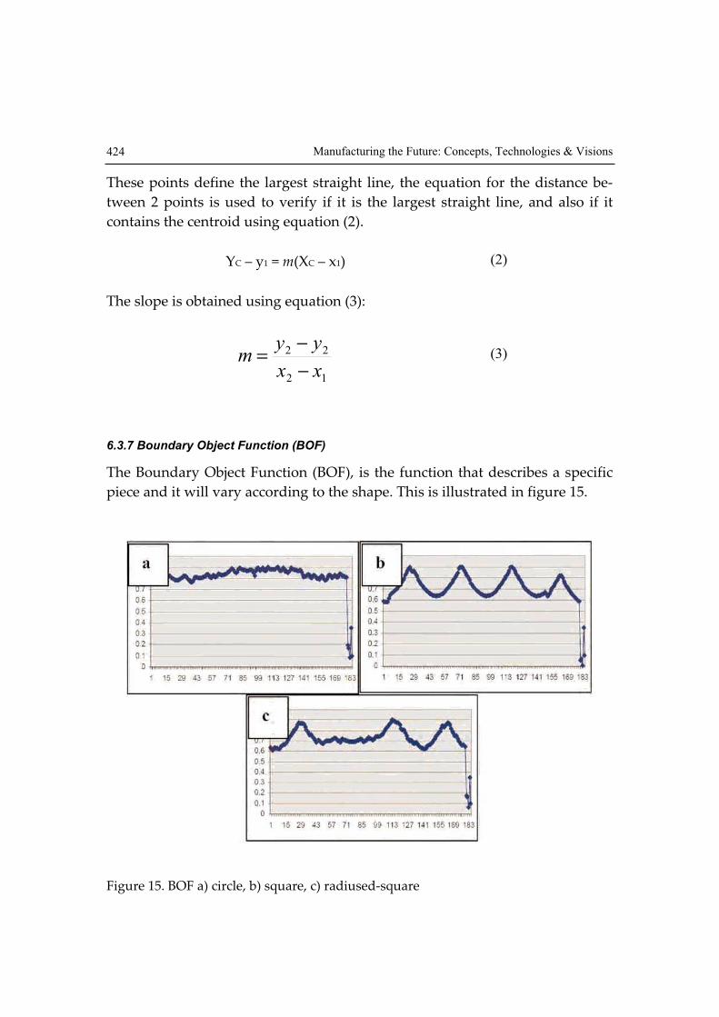
6.3.7 Boundary Object Function (BOF)
The Boundary Object Function (BOF), is the function that describes a specific
piece and it will vary according to the shape. This is illustrated in figure 15.
Figure 15. BOF a) circle, b) square, c) radiused-square

Distributed Architecture for Intelligent Robotic Assembly, Part III: Design… 425
The centroid, the coordinates of the perimeter and the distance from the cen-
troid to the perimeter points are used to calculate the BOF.
With the coordinates P1 (X1, Y1) and P2 (X2, Y2), equation (4) is applied:
2
12
2
1221 )()(),( YYXXPPd −+−= (4)
6.3.8 Descriptive vector generation and normalization
Once the information has been processed, a descriptive vector is generated.
This vector is the input to the neural network. The descriptive vector is called
CFD&POSE and it is conformed by:
=
ID
Z
Y
X
D
D
D
D
POSECFD
c
c
n
φ
3
2
1
]&[(5)
where:
- Di is the distance from the centroid to the object’s perimeter point.
- XC, YC, are the coordinates of the centroid.
- φ, is the orientation angle.
- Z is the height of the object.
- ID is a code number related to the geometry of the components.
6.3.9 Information processing in the neural network
The vision system extends the BOF data vectors to 180, plus 4 more data vec-
tors, centroid (Xc, Yc), orientation, height and ID as showed to conform the de-
scriptor vector which is the input to the FuzzyARTMAP neural network. :
Data
1-180
Centroid
181-182
Orientation
183
Height
184
ID
185

Manufacturing the Future: Concepts, Technologies & Visions 426
7. Experimental Results
7.1 Training and recognition on-line
In order to test the architecture, experimental work was carried out with the
distributed manufacturing sytem using the vision system, to achieve the task
and to test the robustness of the ANN, the Fuzzy ARTMAP Neural Network
was trained first with 2808 different patterns corresponding to the described
working pieces and the learning capability was analyzed. Results regarding
the percentage of recognition and the number of generated neurons are shown
in figure 16. The graph shows how the system learned all patterns in three ep-
ochs, creating only 32 neurons to classify 2808 patterns.
Learning convergence
0
20
40
60
80
100
120
1 2 3 4 5
Epochs
%R
eco
ng
intio
n / #
Ne
uro
ns
%Regcongnition
# Neurons
Figure 16. Learning of the neural network
The average time for training was 4.42 ms, whereas for testing was 1.0 ms.
Later a normalization procedure was applied to the descriptor vector
CFD&POSE so that the experimental work employed only 216 patterns corre-
sponding to 72 square, 72 circle and 72 radiused-square components of the
same size. The orientation values were 0, 45, 90, 135, 180, 215, 270 and 315 de-
grees. With these training patterns set, the system was able to classify correctly

Distributed Architecture for Intelligent Robotic Assembly, Part III: Design… 427
100% of the pieces presented on-line even if they were not of the same size,
orientation or locations and for different light conditions. The pieces used to
train the neural network are shown in figure 17 and figure 18 which show dif-
ferent graphs corresponding to different descriptor vectors for different posi-
tions, sizes and illumination conditions of these components.
Figure 17. Workpieces used to create the initial knowledge base
Figure 18. workpieces used to test the system. a) circle, b) square, c) radiused-square
several tests with different geometry, positions and light conditions, were carried out
on-line.
Manufacturing the Future: Concepts, Technologies & Visions 428
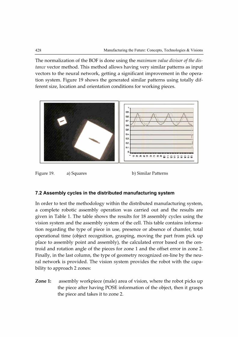
The normalization of the BOF is done using the maximum value divisor of the dis-
tance vector method. This method allows having very similar patterns as input
vectors to the neural network, getting a significant improvement in the opera-
tion system. Figure 19 shows the generated similar patterns using totally dif-
ferent size, location and orientation conditions for working pieces.
Figure 19. a) Squares b) Similar Patterns
7.2 Assembly cycles in the distributed manufacturing system
In order to test the methodology within the distributed manufacturing system,
a complete robotic assembly operation was carried out and the results are
given in Table 1. The table shows the results for 18 assembly cycles using the
vision system and the assembly system of the cell. This table contains informa-
tion regarding the type of piece in use, presence or absence of chamfer, total
operational time (object recognition, grasping, moving the part from pick up
place to assembly point and assembly), the calculated error based on the cen-
troid and rotation angle of the pieces for zone 1 and the offset error in zone 2.
Finally, in the last column, the type of geometry recognized on-line by the neu-
ral network is provided. The vision system provides the robot with the capa-
bility to approach 2 zones:
Zone 1: assembly workpiece (male) area of vision, where the robot picks up
the piece after having POSE information of the object, then it grasps
the piece and takes it to zone 2.

Distributed Architecture for Intelligent Robotic Assembly, Part III: Design… 429
Zone 2: peg-in-hole assembly (female) area of vision, here the visually
guided robot approaches the zone where the female component is
located to achieve the assembly task and releasing the control of the
operation to the SIEM assembly system (Corona-Castuera & Lopez-
Juarez, 2006).
POSE 1 means the location estimation of a workpiece within the zone 1, and
POSE 2 means the location estimation within the zone 2 of the work
piece/counterpart.
Grasp testing (zone 1) was accomplished for each geometry; every one was
placed three times within the vision area, incrementing 10 degrees its orienta-
tion and changing the locations in four defined poses. In the zone 2, the loca-
tion of the female component was fixed, hence the angle. However, It is impor-
tant to mention that the POSE was unknown to the assembly controller.
ZONE 1 Zone 1 Error ZONE 2 Zone 2 Error #IN P Ch
TC
(min)
TA
(s) Xmm Ymm RZ° Xmm Ymm RZ° Xmm Ymm Xmm Ymm NC
1 S Y 1:15 32.5 62.4 144.1 10 0.2 -1.3 0 84.6 102.1 0.3 -1 Y
2 S Y 1:15 30.4 62.4 45.7 12 1.8 0.2 2 85.6 101.1 -0.7 0 Y
3 S Y 1:15 31.8 178.7 47.7 23 0.9 -0.8 3 84.7 100.9 0.2 0.2 Y
4 R Y 1:11 30.1 181.6 147 29 -0.3 -0.7 -1 84.7 100.6 0.2 0.5 Y
5 R Y 1:14 29.4 62.4 145.1 36 0.2 -0.3 -4 84.9 100.7 0 0.4 Y
6 R Y 1:19 29.6 67.3 44.8 48 3.1 -0.7 -2 85.3 101.6 -0.4 -0.5 Y
7 C Y 1:15 29.6 180.6 49.6 57 1 1.1 -3 84.6 102.4 0.3 -1.3 Y
8 C Y 1:13 30.2 180.6 148 77 -0.7 0.3 7 84.3 101 0.6 0.1 Y
9 C Y 1:14 30.2 61.5 146 79 -0.7 0.6 -1 83.9 101.6 1 -0.5 Y
10 S N 1:18 29.9 63.4 45.7 83 -0.8 0.2 -7 85.4 100.5 -0.5 0.6 Y
11 S N 1:19 30.4 179.6 48.6 104 0 0.1 4 83.2 100.8 1.7 0.3 Y
12 S N 1:22 34.6 180.6 147 104 -0.7 -0.7 -6 83.2 101.8 1.7 -0.7 Y
13 R N 1:22 38.3 61.5 146 119 -0.7 0.6 -1 84.8 102.8 0.1 -1.7 Y
14 R N 1:22 36.8 63.4 43.8 126 -0.8 1.7 -4 83.6 101.8 1.6 -0.7 Y
15 R N 1:24 36.6 179.6 47.7 138 0 -0.8 -2 83.2 101.7 1.7 -0.6 Y
16 C N 1:17 30.5 182.6 149 150 1.3 1.3 0 83.7 101.2 1.2 -0.1 Y
17 C N 1:15 28.3 63.4 146 155 1.2 0.6 -5 84.6 100.7 0.3 0.4 Y
18 C N 1:15 29.7 64.4 47.7 174 0.2 2.2 4 83.9 101.1 1 0 Y
Table 1. 18 assembly cycles using the vision system and the assembly system (Eight-
een different assembly cycles, where IN= Insertion, P=piece, Ch=chamfer present,
TC=Assembly cycle time, TA= Insertion time, NC=correct neural classification,
S=square, R=radiused-square, C=circle, N=no and Y=yes).

Manufacturing the Future: Concepts, Technologies & Visions 430
The first 9 assembly cycles were done with female chamfered components and
the last 9 with chamferless components.
The average time of the total cycle is 1:50.6 minutes and the minimum time is
1:46 minutes, the longest time is: 1:58 minutes.
The average of the error made in both zones is: 0.8625 mm, the minimum is: 0
mm while the maximum is 3.4 mm.
The average of the error angle is: 4.27 ° , the minimum is: 0° and the maximum
is 9°.
The figure 20, shows eighteen different X and Y points where the robot might
reach the male component showed as error X(mm) and error Y(mm).
Figure 20. Positional error referenced to real centroid in male component
In the assembly area the robot gets vision guided capabilities to approach the
zone to the centre of the workpiece/counterpart, the figure 22 shows eighteen
different X and Y points where the robot might reach the female and releases
control to force/sensing system.
The 18 assembly cycles were done successfully. The figures 20, 21 y 22 show
that all the poses given by the vision system are inside the error limits in both
areas: zone 1 and zone 2. This permitted to have a 100% of success in the total
assembly cycle operation
Figure 21 shows the angle error for orientation grasping purpose

Distributed Architecture for Intelligent Robotic Assembly, Part III: Design… 431
Figure 21. Rotational error for orientation grasp
Figure 22. Positional error referenced to real centroid in female component.

Manufacturing the Future: Concepts, Technologies & Visions 432
8. Conclusions and future work
A novel methodology for fast object recognition and POSE estimation for as-
sembly components in a distributed manufacturing system has been described.
Experimental results show the methodology. Issues regarding image process-
ing, centroid and perimeter calculation are illustrated. The methodology was
tested on a distributed manufacturing system using an industrial manipulator
to perform assembly operations. Results show the feasibility of the method to
send grasping and morphologic information (coordinates and classification
characteristics) to the robot in real-time. A robust positioning system that cor-
rected errors due to wheel sliding was implemented using visual feedback in-
formation. The overall methodology was implemented and integrated in a
manufacturing cell showing real performance of industrial processes. Accurate
recognition of assembly components and workpieces identification was suc-
cessfully carried out by using a FuzzyARTMAP neural network model. The
performance of this model was satisfactory with recognition times lower than
5 ms and identification rates of 100%. Experimental measurements showed ±3
millimeter of precision error in the information sent to the robot. The orienta-
tion angle error for the pieces was up to ±9 degrees, which was still good
enough for the robot to grasp the pieces. Future work is envisaged using the
intelligent distributed manufacturing system with multimodal and fusion sen-
sor capabilities using the methodology presented in this work. Current work
addresses the use of ANN’s for assembly and object recognition separately;
however work is oriented towards the use of the same neural controller in a
hierarchical form for all other different sensorial modalities (Lopez-Juarez &
Rios-Cabrera, 2006).
9. References
Aguado A., E. Montiel, M. Nixon . Invariant characterization of the Hough
Transform for pose estimation of arbitrary shapes. Pattern Recognition 35
, 1083-1097 , Pergamon, (2002).
Best Paul J.and Neil D. McKay. A Method for Registration of 3-D Shapes. IEEE
Transactions on Pattern Analysis and Machine Intelligence, vol 14 No. 2,
February (1992).
Bribiesca E. A new Chain Code. Pattern Recognition 32 , Pergamon, 235-251 ,
(1999).

Distributed Architecture for Intelligent Robotic Assembly, Part III: Design… 433
Bone Gary M. and David Capson. Vision-guided fixturless assembly of auto-
motive components. Robotics and Computer Integrated Manufacturing
19, 79-87 , (2003).
Carpenter Gail A. and Stephen Grossberg. Computer Vision, Graphics, and
Image Processing. A Massively Parallel Architecture for a Self-
Organizing Neural Pattern Recognition Machine. Academic Press, Inc.
Pp. 54-115. 1987.
Carpenter Gail A. and Stephen Grossberg, John H Reynolds. ARTMAP: Su-
pervised Real-Time Learning and Classification of Nonstationary Data by
Self-Organizing Neural Network. Neural Networks. Pp 565-588. 1991.
Cem Yüceer adn Kema Oflazer, A rotation, scaling and translation invariant
pattern classification system. Pattern Recognition, vol 26, No. 5 pp. 687-
710, (1993).
Cervera Enric and Angel P. del Pobil. Programming and learning in real world
manipulation tasks. Proc. 1997 IEEE/RSJ Int Conf on Inteligent Robot and
Systems, 1:471-476, September (1997).
Chen K., Efficient parallel algorithms for computation of two-dimensional im-
age moments, Pattern Recognition 23, 109-119, (1990).
Chin-Hsiung Wu et al. Anew computation of shape moments via quadtree de-
composition. Pattern Recognition 34 , 1319-1330, Pergamon, (2001).
Corona Castuera J. and Ismael Lopez-Juarez, “Intelligent Task Level Planning
for Robotic Assembly: Issues and Experiments”, Mexican International
Conferences on Artificial Intelligence, México 2004, ISBN 3-540-21459-3,
Springer-Verlag.
Corona Castuera, J; Lopez-Juarez, I. (2006). Distributed Architecture for Intel-
ligent Robotic Assembly, Part II: Design of the task planner.
ADVANCED TECHNOLOGIES: Research-Development-Application.
Submitted for publication.
Dickmanns E. “Vehicles capable of dynamic vision: a new breed of technical
beings?”, Artifical Intelligence, vol 103, pp, 49-76, August (1998).
Freeman H., Computer processing of line drawings images, ACM Comput.
Surveys 6 57-97, (1974).
Freeman H., On the encoding of arbitrary geometric configurations, IRE Trans.
Electron. Comput. EC-10 , 260-268, (1961).
Gupta Madan M., G. Knopf. Neuro-Vision Systems: a tutorial. A selected re-
print Volume IEEE Neural Networks Council Sponsor, IEEE Press, New
York, 1993.

Manufacturing the Future: Concepts, Technologies & Visions 434
Gupta Madan M., G. Knopf. Neuro-Vision Systems: Part 6 Computational Ar-
chitectures and Applications. A selected reprint Volume IEEE Neural
Networks Council Sponsor, IEEE Press, New York, 1993.
Gonzalez-Galvan Emilio J. et al. Application of Precision-Enhancing Measure
in 3D Rigid-Body Positioning using Camera-Space Manipulation, The In-
ternational Journal of Robotics Research, vol 16, No. 2, pp. 240-257, April
(1997).
Geoffrey G. Towell; Jude W. Shavlik. Knowledge-based artificial neural net-
worksArtificial Intelligence. Vol. 70, Issue 1-2, pp. 119-166. 1994
Robert S. Feldman, Understanding Psychology, 3rd edition. Mc Graw-Hill,
Inc., 1993.
Grossberg Stephen, Adaptive Pattern Classification and universal recoding II:
Feedback, expectation, olfaction and illusions. Biological Cybernetics.
Vol. 23, pp. 187-202, 1976.
Gullapalli Vijaykumar; Judy A. Franklin; Hamid Benbrahim. Acquiring robot
skills via reinforcement learning. IEEE Control Systems, pages 13-24, Feb-
ruary (1994).
Hager G., et al, Calibration-free visual control using projective invariance, pro-
ceedings ICCV, pp 1009-1015, (1995).
Hiroshi Murase and Shree K. Nayar, Visual Learning and Recognition of 3-D
Objects from Appearenace. International Journal of Computer Vision, 14,
5-24 (1995).
Hoska DR. Fixturless assembly manufacturing. Manuf Eng , 100:49-54 , April
(1988).
Howarth Martin. An investigation of task level programming for robotic as-
sembly. PhD thesis, The Nottingham Trent University, January 1998.
Hu M.K. Visual pattern recognition by moment invariants, IRE Trans Inform
Theory IT-8, 179-187, (1962).
Jörg Stefan et. al. Flexible Robot-Assembly using a Multi-Sensory Approach. In
Proc. IEEE, Int. Conference on Robotics and Automation, San Fco. Calif,
USA (2000), pp 3687-3694.
Kollnig H. and H. Nagel. 3d pose estimation by directly matching polyhedral
models to gray value gradients. International Journal of Computer Vi-
sion, vol 23, No. 3, pp 282.302, (1997).
Kronauer R.E. , Y. Zeevi . Reorganization and Diversification of Signals in Vi-
sion. IEEE Trans. Syst. Man, Cybern., SMC-15,1,91-101. (1985).

Distributed Architecture for Intelligent Robotic Assembly, Part III: Design… 435
Langley C.S., D. Eleuterio GMT, A memory efficient neural network for robotic
pose estimation, In proceedings of the 2003 IEEE International Sympo-
sium on Computational Intelligence in Robotics and Automation, No. 1 ,
418-423, IEEE CIRA, (2003).
Lopez-Juarez I. Howarth M. “Learning, Manipulative Skills with ART”, Proc
2000 IEEE/RSJ Int. Conf. on Intelligent Robots and Systems. October 2000.
Lopez-Juarez I. On-line learning for robotic assembly using artificial neural
networks and contact force sensing. PhD thesis, The Nottingham Trent
University, (2000).
Lopez-Juarez, I; Rios-Cabrera, R. (2006) Distributed Architecture for Intelligent
Robotic Assembly, Part I: Design and Multimodal Learning.
ADVANCED TECHNOLOGIES: Research-Development-Application.
Submitted for publication.
Mundy J.L. , Object Recognition based on geometry: progres over 3 decades.
Phylosophical Transactions: mathematical, physical and engineering sci-
ences, 356: 1213-1231, 1998.
Ngyuen W. and J.K. Mills. Multirobot control for flexible fixturless assembly of
flexible sheet metal autobody parts. In proceedings of IEEE International
Conference on Robotics and Automation, , pp. 2340-2345, (1996).
Papanikolopoulous N. P. and K. Khosla. Adaptive robotic visual tracking: the-
ory and experiments. IEEE Transactions on Automatic Controller, vol. 38,
No. 3, pp 429-445, (1993).
Peña-Cabrera M. et al, “A Learning Approach for On-Line Object Recognition
in Robotic Tasks”, Mexican International Conference on Computer Sci-
ence ENC 2004, México, IEEE Computer Society Press. (2004).
Peña Cabrera M. et al, “Un Proceso de Aprendizaje para Reconocimiento de
Objetos en Línea en Tareas Robotizadas”, 3ra Conferencia Iberoamerica-
na en Sistemas, Cibernética e Informática CISCI 2004, del 21 al 25 de julio
del 2004, Orlando, Florida EE.UU.
Philips W., A new fast algorithm for moment computation, Pattern Recogni-
tion 26, 1619-1621, (1993).
Plut W.J. and G.M. Bone. Limited mobility grasps for fixturless assembly, In
proceedings of the IEEE International Conference on Robotics and
Automation , Minneapolis, Minn., pp. 1465-1470, (1996).
Plut W.J. and G.M. Bone. 3-d flexible fixturing using multi-degree of freedom
gripper for robotics fixturless assembly. In proceedings of the IIEEE In-

Manufacturing the Future: Concepts, Technologies & Visions 436
ternational Conference on Robotics and Automation, Alburquerque,
NM, pp. 379-384, (1997).
Shaogang Gong, Hilary Buxton, (2002). Understanding Visual Behaviour, Im-
age and Vision Computing, vol 20, No.12, Elsevier Science., (2002).
Shepard R.N. and S Hurwitz. Upwards direction, mental rotation and dis-
crimination of left and right turns in maps. Cognition, 18, 161-193, 1984.
Shingchern D. You , Gary E. Ford, Network model for invariant object recogni-
tion. Pattern Recognition Letters 15, 761-767, (1994).
Stavros J. and Paulo Lisboa. Transltion, Rotation , and Scale Invariant Pattern
Recognition by High-Order Neural networks and Moment Classifiers.,
IEEE Transactions on Neural Networks, vol 3, No. 2 , March (1992).
Stephen A. Underwood et al. Visual Learning from Multiple Views. IEEE
Transactions on Computers, vol c-24, No. 6 , June (1975).
Torralba A. and A. Oliva. Depth Estimation from Image Structure. IEEE Trans-
actions on Pattern Analysis and Machine Intelligence, vol 24, No. 9 Sep-
tember (2002).
Uhr L. Psychological motivation and underlying concepts . Structured Com-
puter Vision, S. Tanimoto, A. Klinger Ed. , 1-30, (1980).
Ulman S., Visual Routines Cognition, 18: 97-159, 1984.
Wu L., S. L. Oviatt, P. R. Cohen, “ Multimodal Integration – A Statical View”,
IEEE Transactions on Multimedia, vol 1 , Num. 4, pp 334-341, (1999).
Yong-Sheng Chen et al. Three dimensional ego-motion estimation from motion
fields observed with multiple cameras. Pattern Recognition 34, 1573-1583,
Pergamon , (2001).

Manufacturing the FutureEdited by Vedran Kordic, Aleksandar Lazinica and Munir Merdan
ISBN 3-86611-198-3Hard cover, 908 pagesPublisher Pro Literatur Verlag, Germany / ARS, Austria Published online 01, July, 2006Published in print edition July, 2006
InTech EuropeUniversity Campus STeP Ri Slavka Krautzeka 83/A 51000 Rijeka, Croatia Phone: +385 (51) 770 447 Fax: +385 (51) 686 166www.intechopen.com
InTech ChinaUnit 405, Office Block, Hotel Equatorial Shanghai No.65, Yan An Road (West), Shanghai, 200040, China
Phone: +86-21-62489820 Fax: +86-21-62489821
The primary goal of this book is to cover the state-of-the-art development and future directions in modernmanufacturing systems. This interdisciplinary and comprehensive volume, consisting of 30 chapters, covers asurvey of trends in distributed manufacturing, modern manufacturing equipment, product design process,rapid prototyping, quality assurance, from technological and organisational point of view and aspects of supplychain management.
How to referenceIn order to correctly reference this scholarly work, feel free to copy and paste the following:
Mario Pena Cabrera and Ismael Lopez Juarez (2006). Distributed Architecture for Intelligent Robotic AssemblyPart III: Design of the Invariant Object Recognition System, Manufacturing the Future, Vedran Kordic,Aleksandar Lazinica and Munir Merdan (Ed.), ISBN: 3-86611-198-3, InTech, Available from:http://www.intechopen.com/books/manufacturing_the_future/distributed_architecture_for_intelligent_robotic_assembly_part_iii__design_of_the_invariant_object_r

© 2006 The Author(s). Licensee IntechOpen. This chapter is distributed under the terms of theCreative Commons Attribution-NonCommercial-ShareAlike-3.0 License, which permits use,distribution and reproduction for non-commercial purposes, provided the original is properly citedand derivative works building on this content are distributed under the same license.