Dispatcher/Operator Board Assembly Instructions · Dispatcher/Operator Board Assembly Instructions...
11
www.modelrailroadcontrolsystems.com/telephone Dispatcher/Operator Board Assembly Instructions Revision v0.1 07/09/2017 Seth Neumann, [email protected] 415-602-1510 Revision History v0.1 07/08/2017 SN Table of Contents 1. INTRODUCTION............................................................................................................................................... 2 2. DISPATCHER/OPERATOR INTERFACE OVERVIEW............................................................................................ 2 3. CONNECTIONS ................................................................................................................................................ 3 3.1. POWER ........................................................................................................................................................... 3 3.2. TIP AND RING (TELEPHONE) ........................................................................................................................... 3 3.3. MICROPHONE ................................................................................................................................................. 4 3.4. SPEAKER ......................................................................................................................................................... 4 3.5. FOOTSWITCH .................................................................................................................................................. 4 3.6. REMOTE VOLUME CONTROLS ........................................................................................................................ 4 4. INSTALLATION AND ADJUSTMENT................................................................................................................... 5 4.1. MOUNTING ..................................................................................................................................................... 5 4.2. INITIAL TEST AND SETUP................................................................................................................................ 6 5. BILL OF MATERIALS ........................................................................................................................................ 7 6. ASSEMBLY ..................................................................................................................................................... 8 7. SCHEMATIC .................................................................................................................................................. 10 8. HISTORY AND BACKGROUND ........................................................................................................................ 11 9. SUBSTITUTION .............................................................................................................................................. 11 10. VARIATIONS ................................................................................................................................................. 11 Table of Figures FIGURE 1 DISPATCHER/OPERATOR TOP VIEW ....................................................................................................................... 3 FIGURE 2 DS/OP BOARD AND EBF31A MOUNTED IN 12" DINRAIL ..................................................................................... 5 FIGURE 3 DS/OP COMPONENT LAYOUT ................................................................................................................................ 8 FIGURE 4 TOP OF BOARD ....................................................................................................................................................... 8 FIGURE 5 DS/OP SCHEMATIC .............................................................................................................................................. 10
-
Upload
hoangduong -
Category
Documents
-
view
237 -
download
0
Transcript of Dispatcher/Operator Board Assembly Instructions · Dispatcher/Operator Board Assembly Instructions...
www.modelrailroadcontrolsystems.com/telephone
Dispatcher/Operator Board
Assembly Instructions
Revision v0.1 07/09/2017
Seth Neumann, [email protected]
415-602-1510
Revision History
v0.1 07/08/2017 SN
Table of Contents 1. INTRODUCTION ............................................................................................................................................... 2
2. DISPATCHER/OPERATOR INTERFACE OVERVIEW ............................................................................................ 2
3. CONNECTIONS ................................................................................................................................................ 3
3.1. POWER ........................................................................................................................................................... 3
3.2. TIP AND RING (TELEPHONE) ........................................................................................................................... 3
3.3. MICROPHONE ................................................................................................................................................. 4
3.4. SPEAKER ......................................................................................................................................................... 4
3.5. FOOTSWITCH .................................................................................................................................................. 4
3.6. REMOTE VOLUME CONTROLS ........................................................................................................................ 4
4. INSTALLATION AND ADJUSTMENT ................................................................................................................... 5
4.1. MOUNTING ..................................................................................................................................................... 5
4.2. INITIAL TEST AND SETUP ................................................................................................................................ 6
5. BILL OF MATERIALS ........................................................................................................................................ 7
6. ASSEMBLY ..................................................................................................................................................... 8
7. SCHEMATIC .................................................................................................................................................. 10
8. HISTORY AND BACKGROUND ........................................................................................................................ 11
9. SUBSTITUTION .............................................................................................................................................. 11
10. VARIATIONS ................................................................................................................................................. 11
Table of Figures FIGURE 1 DISPATCHER/OPERATOR TOP VIEW ....................................................................................................................... 3
FIGURE 2 DS/OP BOARD AND EBF31A MOUNTED IN 12" DINRAIL ..................................................................................... 5
FIGURE 3 DS/OP COMPONENT LAYOUT ................................................................................................................................ 8
FIGURE 4 TOP OF BOARD ....................................................................................................................................................... 8
FIGURE 5 DS/OP SCHEMATIC .............................................................................................................................................. 10

May 9, 2017 www.modelrailroadcontrolsystems.com/telephone Page 2 of 11
1. INTRODUCTION
This document describes the functional blocks of the Dispatcher/Operator interface (Active
Telephone Speech Network) and how to assemble it.
2. DISPATCHER/OPERATOR INTERFACE OVERVIEW
The Dispatcher/Operator interface (DSOP):
• operates on 24 volts, draws about 15 mA (can share a power supply with our EBF31A or
other 24V battery feed arrangement)
• Independent receive, and transmit volume controls to ensure the DS/OP can hear and be
heard
• “break-in” (when a station is trying to talk to the DS/OP while the DS/OP is talking) and
output phase adjustments to control feedback when used with a desk mic (you must use a
directional or cardioid pattern mic for reliable mic/speaker operation)
• Does not draw DC power from the Dispatcher’s “Train Wire”
• Supports “computer” headsets with separate 1/8” (3.5mm) plugs, or free standing
microphone/speaker arrangements, including “candlestick” or “scissor” style telephones
modified for dynamic or electret mics
• Jumpers for tip/ring/sleeve or tip/sleeve plugs on audio inputs and outputs
• Supports dynamic and electret microphones with built in electret power supply (for computer
headsets)
• Push (stomp)-to-talk voice switching with screw terminals for footswitch
• Optional connections for remote volume controls
• 2 RJ11 jacks for connection to Dispatcher’s train line as well as screw terminals
• Uses Regulated 24VDC @ 15 mA on 2.5mm barrel jack, screw terminals, or on pair 3 of the
RJ11
• Hybrid Null adjust to reduce line noise
• 2.75” x 6.5” (10x16 cm) form factor fits in a piece of 12” DINRail next to an EBF31A for a
complete Dispatcher and Battery Feed Solution for a Dispatcher’s Train Line!
The EBF31A consists of three main sections.
• 2-4 wire hybrid matches microphone and speaker to 2 wire phone line with null adjustment
• Microphone control circuit (footswitch) with “talk” indicator LED
• 600 ohm line level output to external amplified speaker
• Adjustable pre-amplifiers for mic level, receive level and break-in
All components are through-hole technology for ease of assembly and repair.
Connectors are provided on RJ11 (for tip, ring – first pair and power on third pair), 2.5mm center
positive barrel connector (for power) and 3.5mm stereo jack for microphone and line level audio.
There is a 5mm 2 position terminal strip for a footswitch. In addition there is a 4 position 0.100”
terminal strip for tip and ring and 24V(+) and ground in parallel with the RJ11. Pads are
provided for a second 4 position 0.100” terminal strip.

May 9, 2017 www.modelrailroadcontrolsystems.com/telephone Page 3 of 11
Figure 1 Dispatcher/Operator Top View
3. CONNECTIONS
3.1. POWER
The DS/OP uses regulated 24V DC. 15 mA is sufficient, although most commercial 24 VDC
supplies start at 1A. Modern “Wall Warts,” open frame power modules, or traditional telephone
supplies may be used. If your supply has a 2.5mm center positive plug, you may plug it in to the
barrel jack, J1. If not use, pins 1 and 2 of SL1 or SL2. Pin 1 is +24V and Pin 2 is ground. Since the
DS/OP draws a maximum of 15mA, you can use wire as small as 24 Ga for the power connections
which will easily fit into the miniature screw terminals. D2 will protect the board if you connect
power upside down, but the circuit will not work until you have polarity correct.
3.2. TIP AND RING (TELEPHONE)
The two sides of a traditional telephone line are called TIP (the more grounded side) and RING (the
side towards supply or “battery”). These terms derive from the Tip/Ring/Sleeve plug (like a modern
stereo plug) used on manual switchboards. Tip and Ring are available on the center pair of the RJ11
jack so you can plug a test phone directly into the DS/OP: if you can hear yourself talk through your
microphone on the handset of the test phone you’re on the air! If you want to distribute signal
through telephone style punch blocks or barrier strips, use pins 3 and 4 of JP3.
Do not plug a 6 wire phone (or DCC command bus) cable from the DS/OP directly into a V2.0N or
earlier EF31A as the auxiliary contact will short out the power. Forthcoming EBF31As will share
power on the third pair and move the “off hook” contact to the second pair.
May 9, 2017 www.modelrailroadcontrolsystems.com/telephone Page 4 of 11
3.3. MICROPHONE
The microphone is connected to JP6, a 3.5mm jack. Adapters are available from all the usual sources
to reduce ¼” phone plugs to 3.5mm. You can either a dynamic or an electret mic with the DS/OP.
There is an internal power supply to drive an electret mic (usually used in “computer” headsets). No
adjustment is required to use an electret mic. If you don’t want the electret power, don’t install R10
and D1.There is a jumper JP4 to short the tip and ring of the mic together if you are using a stereo mic
but that should not be necessary.
3.4. SPEAKER
The speaker is connected to JP7, a 3.5mm jack. As noted above adapters are available to convert
3.5mm to other formats. This jack is for a powered computer speaker or the earphones of a computer
headset. Again, a there is a jumper, JP8, to short the tip and ring of together if you are driving
powered stereo speakers, such as typical computer speakers. You can also drive an amplifier for
larger speakers with this output. There is a phase jumper, JP5, that can be move to change phase of
the output. This is sometimes useful in controlling feedback in a mic/speaker/footswitch installation.
The jumper must be in and connected one way or the other to obtain output.
3.5. FOOTSWITCH
A 5mm screw terminal, JP9, is provided for us with a footswitch. The footswitch should be wired as
normally open (form A) and depressing the pedal should close the switch. The LED above the
connector will illuminate when the contact is closed and the mic is active. In some headset
arrangements the mic may be left on continuously by running a jumper from one terminal of JP9 to
the other. A good noise cancelling headset will provide enough isolation to prevent feedback.
However any station coming off hook will hear the DS/OP talking with anyone in his space.
3.6. REMOTE VOLUME CONTROLS
The three volume controls: microphone, receiver and break-in, may be mounted remotely. In this case
rather than using the screwdriver adjusted potentiometers on the board, 0.100 screw terminal strips or
headers mounted in positions JP 1 through 3 respectively. A suitable cable is then run from the
terminal to the remote pot. MRCS offers the pots as accessories. We recommend you only remote
audio level, JP 2, but if you do remote the break-in and mic pots, remember to shield the mic
connection as it is low-level. Always keep these cables as short as possible and away from possible
sources of interference.
May 9, 2017 www.modelrailroadcontrolsystems.com/telephone Page 5 of 11
4. INSTALLATION AND ADJUSTMENT
4.1. MOUNTING 1. Find a location close to your battery feed source
2. The DS/OP is designed to snap into 70mm DINRail (a plastic track system) and you can cut notches in the
rail to clear the various connectors. You may need to remove one of the “vanes” to allow for easier
installation by scribing it with a hobby knife. Alternately you can use the four holes, I use ¾” pan head
sheet metal screws and ¼” standoffs.
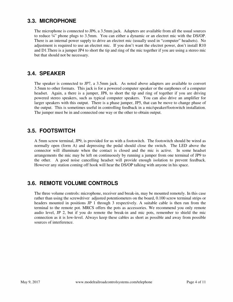
Figure 2 DS/OP board and EBF31A Mounted in 12" DINRail
3. Either plug a 2.5mm 24V wall wart into the power jack or run 24VDC and ground to the marked terminals
on the 4 position green, 0.100” connecting block above the left RJ11 connector. Power can be daisy
chained from the EBF31A. You can’t hurt the DSOP board by connecting upside down, but nothing will
happen. Check with a voltmeter: Black lead to ground, Red lead to 24v (it’s marked on the board).
4. Connect your footswitch to the Blue, 2 position, screw terminal block marked “Push to Talk.” The
footswitch should be normally open and the contacts should close when you stomp down on it.
5. Plug your microphone (mic side of headset) into the 3.5 mm jack marked “Microphone”
6. Plug your powered speaker (earphone side of headset) into the 3.5 mm jack marked “Audio Out”
7. Make sure there is a white jumper on the “Output Phase” header (JP5) above the “Audio Out” jack. The
center and one side or the other should be connected; it isn’t important which side at this point.
8. You don’t need a jumper on either of the headers beside the jacks unless you’ve got a stereo device and
want audio to come out on both channels.
May 9, 2017 www.modelrailroadcontrolsystems.com/telephone Page 6 of 11
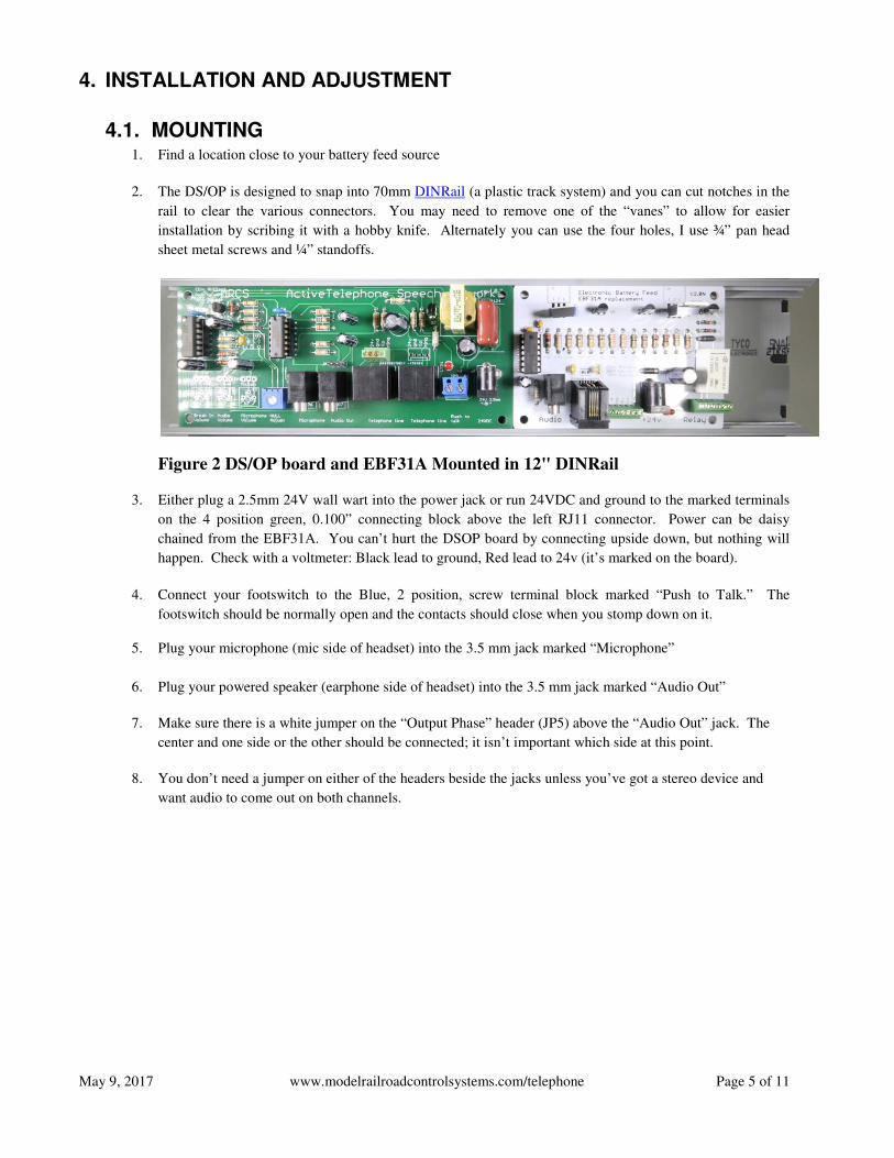
4.2. INITIAL TEST AND SETUP 1. Smoke test: apply power and look for sparks or smoke. If none observed, leave power on for five minutes
and check that nothing (ICs, transistors, resistors) is warm and that nothing smells of burning electronics.
(Note: The electronics Gods can be propitiated by sacrificing a small goat or an old locomotive <g>).
Seriously: check your wiring.
2. Null the hybrid: Have someone take a couple of phones on the line off hook, then while listening through
the headphones or speaker, adjust the “Null Adjust” pot about 1 third from the left on the bottom. There
will be a low level rushing or hissing noise, tweak the pot until the noise is at a minimum.
3. Adjust the transmit volume: stomp on the foot switch and talk in a normal voice: a 10 count or standard text
(recite the Gettysburg address or whatever they made you memorize in school across the border) and have
your helper(s) listen with 1 or 2 phones off hook. You may want to set it a little high as the room will be
noisier during an op session. Use the “Microphone Volume” pot for this adjustment.
4. Adjust the receive volume: have your helper talk to you from one of the stations in a normal voice, Use the
“Audio Volume” pot to make this adjustment. Note that we anticipate that working adjustments during a
session will be made with the volume control on a powered speaker or on the lanyard of the headset but
you can use a remote volume control if you opted for that.
5. Adjust Break-In Volume and Feedback control: In prototypical dispatching party lines, another station
upon hearing something copied incorrectly, is supposed to break in and bring the issue to the DS’ attention.
The break-in Volume pot adjusts how much this audio is muted when the foot switch is active. This helps
prevent feedback in systems with an open Mic and Speaker (generally not a problem with headsets). This
volume should be set as high as is comfortable for the DS without causing feedback. Normal steps to
control feedback are: use a directional or cardioid pattern mic, placement of speaker and mic with respect
to one another (mic not pointing at speaker) and the phase jumper can be changed.

May 9, 2017 www.modelrailroadcontrolsystems.com/telephone Page 7 of 11
5. BILL OF MATERIALS
Part Quan Value Description vendor p/n
BOARD1 1 BOARD69X100
C1,C7,C8,C9 4 10 uf @ 50 Electrolytic CAPACITOR, American symbol Jameco 29891
C2, C6 2 0.1uF (104) CAPACITOR, American symbol Jameco 25523
C3 1 1uF@50V POLARIZED CAPACITOR, American symbol Jameco 29831
C5 1 .33uF CAPACITOR, American symbol Jameco 138237
C10,C11 2 100 uF @ 50V POLARIZED CAPACITOR, American symbol Jameco 29962
C12 1 2.2uF MYLAR_CAP Digikey Digikey P10983-ND
D1 1 1N4734A 5.6 V Zener Diode Jameco 36118
D2 1 1N5819-B 1.0A SCHOTTKY BARRIER RECTIFIER Jameco 177965
IC1, IC2 2 LM324N OP AMP Jameco 23683
J1,J2 2 RJ14 DigikeyWM5431-ND Digikey
WM5431-
ND
JP1,2,3,5 4 Remote POT, Phase
JP4,8 1 PHOENIX CONNECTOR
JP6,7 2 RS 2168149 3.5mm Audio Jack Jameco 2168149
JP9 1 PHOENIX CONNECTOR 2x5mm Jameco 2094485
JP10 1 Jameco 101187-RA DC POWER JACK Jameco 2094485
LED1 1 LEDs eBay 2186603
Q1 1 2N4401/3904/2222 NPN Transistor Jameco 783498
Q2 1 2N4403/3906 PNP Transistor Jameco 38447
R1 1 10K 3386 Series Jameco 43001
R2, R12 2 100K 3386 Series Jameco 43027
R7 1 500K 3386 Series Jameco 63212
R3,13,14,15,17 5 22K Resistor Jameco 691180
R4 1 2.2K Resistor Jameco 690945
R5,6,8,20 4 100K Resistor Jameco 691340
R9,10 2 15K Resistor Jameco 691147
R11,
18,19,22,23 5 10K Resistor Jameco 691104
R16 1 680 Resistor Jameco 690822
R21 1 47K Resistor Jameco 691260
SL1,2 2 4 position 0.100 screw terminal E-Salon
T1 1 TY-145P Jameco 630459
Table 1- Bill of Materials

May 9, 2017 www.modelrailroadcontrolsystems.com/telephone Page 8 of 11
6. ASSEMBLY
Figure 3 DS/OP Component Layout
Figure 4 Top of Board
All of the components are through-hole technology with wire leads. A useful tool is a lead bender
for forming the leads at 90 degrees for easy insertion into the pad holes. Start with inserting the
lower height components. The general rule is to install the lowest components first, working
towards components that are higher off the board. This enables you to support the low components
as you solder them.
May 9, 2017 www.modelrailroadcontrolsystems.com/telephone Page 9 of 11
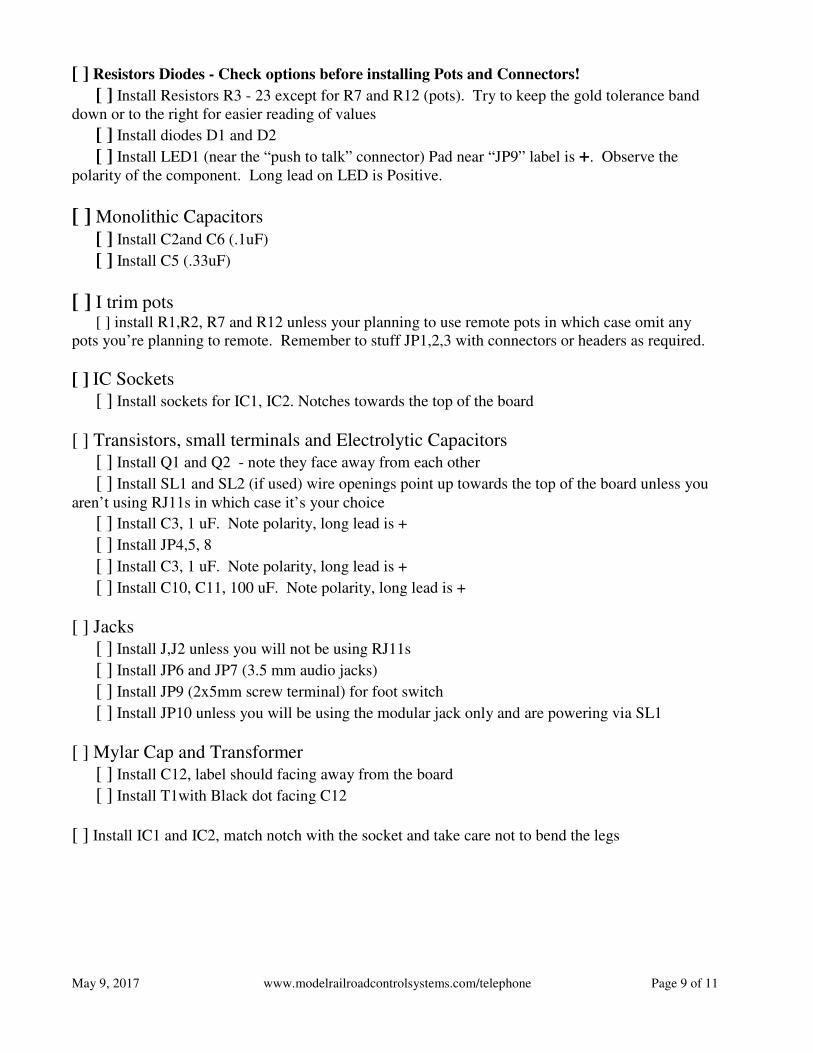
[ ] Resistors Diodes - Check options before installing Pots and Connectors!
[ ] Install Resistors R3 - 23 except for R7 and R12 (pots). Try to keep the gold tolerance band
down or to the right for easier reading of values
[ ] Install diodes D1 and D2
[ ] Install LED1 (near the “push to talk” connector) Pad near “JP9” label is +. Observe the
polarity of the component. Long lead on LED is Positive.
[ ] Monolithic Capacitors
[ ] Install C2and C6 (.1uF)
[ ] Install C5 (.33uF)
[ ] I trim pots [ ] install R1,R2, R7 and R12 unless your planning to use remote pots in which case omit any
pots you’re planning to remote. Remember to stuff JP1,2,3 with connectors or headers as required.
[ ] IC Sockets
[ ] Install sockets for IC1, IC2. Notches towards the top of the board
[ ] Transistors, small terminals and Electrolytic Capacitors
[ ] Install Q1 and Q2 - note they face away from each other
[ ] Install SL1 and SL2 (if used) wire openings point up towards the top of the board unless you
aren’t using RJ11s in which case it’s your choice
[ ] Install C3, 1 uF. Note polarity, long lead is +
[ ] Install JP4,5, 8
[ ] Install C3, 1 uF. Note polarity, long lead is +
[ ] Install C10, C11, 100 uF. Note polarity, long lead is +
[ ] Jacks
[ ] Install J,J2 unless you will not be using RJ11s
[ ] Install JP6 and JP7 (3.5 mm audio jacks)
[ ] Install JP9 (2x5mm screw terminal) for foot switch
[ ] Install JP10 unless you will be using the modular jack only and are powering via SL1
[ ] Mylar Cap and Transformer
[ ] Install C12, label should facing away from the board
[ ] Install T1with Black dot facing C12
[ ] Install IC1 and IC2, match notch with the socket and take care not to bend the legs

May 9, 2017 www.modelrailroadcontrolsystems.com/telephone
7. SCHEMATIC
Figure
www.modelrailroadcontrolsystems.com/telephone
Figure 5 DS/OP Schematic
Page 10 of 11
May 9, 2017 www.modelrailroadcontrolsystems.com/telephone Page 11 of 11
8. HISTORY AND BACKGROUND
The Dispatcher/Operator Interface grew out of a series of clinics I’ve been presenting since 2004 at
various model railroad events on “Communications for Model Railroads” This material has also
appeared as a 3 part series in the Operations SIG’s journal, the “Dispatcher’s Office” and appears as
chapter 9 in the OPSIG book “A Compendium of Model Railroad Operations”. The most recent
version of the clinic is available on the MRCS website at
http://www.modelrailroadcontrolsystems.com/content/Communications%20for%20Model%20Railro
ads%20new%2020160416.pdf I suggest you familiarize yourself with the book chapter or the clinic
before installing a phone system for your model railroad
Almost every model railroad phone system needs a position for a dispatcher. I’ve published a number
of designs which allow the use of standard audio components to support either
microphone/speaker/footswitch or headset (with or without foot switch) operation. The response
from the field has consistently been: make it simpler to assemble, preferably so that everything just
plugs in. The Dispatcher/Operator Interface provides all of the internal functions needed to support
DS/OP operation and has jacks and terminals to connect all of the devices you’ll need.
As with the EBF31A battery feed board, I worked with Clint Gilliland and John Plocher to bring the
board to production quality. Our focus was to build a reliable board using commonly available
components and keeping the cost within reason for model railroad hobbyists.
9. SUBSTITUTION
In the unlikely event you can’t find the transistors, you can substitute pretty freely: almost any small
signal NPN transistor can be used in place of the 2N4401 for Q1, the 2N3904 is almost an exact
match for the specs. For Q2 the 2N4402 can be replaced by 2N3906.
10. VARIATIONS
Most variations on our products are for connector preferences. This makes sense as connectors are
usually the most expensive components (in this case it’s the transformer and mylar cap) you can use
any 0.100 connector for JP1-4 and JP6, as well as SL1 and 2. You can also solder the board directly
to wires if you’re sure you won’t be moving it.
You can substitute a two position 0.100 connector or header for the LED if you’d like to remote the
LED to provide an “On Air” light. You may need to adjust R23 in that case