DISCRETE ELEMENT SIMULATION OF ROCK CUTTING PROCESSES · DISCRETE ELEMENT SIMULATION OF ROCK...
5
1040 DISCRETE ELEMENT SIMULATION OF ROCK CUTTING PROCESSES Jerzy Rojek 1 , Carlos Labra 2 , Eugenio Oñate 2 1 Institute of Fundamental Technological Research, Polish Academy of Sciences, Pawi skiego 5B, 02-106 Warsaw, Poland. E-mail: [email protected] 2 International Center for Numerical Methods in Engineering (CIMNE), Universitat Politècnica de Catalunya, Campus Nord UPC, 08034 Barcelona, Spain. E-mail: onate, [email protected] Abstract. This paper presents numerical modelling and simulation of rock cutting processes. The model considers a tool–rock system. The rock is modelled using spherical discrete elements. Formulation of the discrete element method has been briefly reviewed. The model has been calibrated by simulation of the UCS and Brazilian tests. Simulation of rock cutting with a single point attack pick of a roadheader has been carried out. The 3D analysis al- lowed us to predict three components of cutting forces. The numerical model of rock cutting has been validated using the results of laboratory cutting tests. A good qualitative and quantitative agreement of numerical results with ex- perimental measurements has been found out. Keywords: DEM, rocks, rock cutting, simulation. Introduction Variety of rock-cutting technologies is used in civil as well as in mining engineering. Fig 1 shows a road- header, a machine used in rock excavation works. Fig 1. Rock excavation with a roadheader The basic physical phenomenon occurring during cutting is rock desintegration under mechanical action of a cutting tool. Design of cutting tools and setting parame- ters of cutting operations requires knowledge about the cutting process. Cutting force is one of the main factors characteriz- ing a cutting process. Theoretical evaluation of the cut- ting force is not an easy task. Simple analytical models, like those developed by Evans (1965) or by Nishimatsu (1972), can provide a very approximate estimation of cutting forces only. Numerical methods based on the continuum models, like finite element methods, have serious problems in modelling discontinuities of the ma- terial occuring during rock cutting (Jonak and Podgórski 2001). The present paper presents possibilities of modelling rock cutting using a discrete element model. The discrete element method takes into account all kinds of disconti- nuities and material failure characterized with fracture and is commonly regarded as a suitable tool to study rock cutting (Huang 1999; Stavropoulou 2006; Su et al. 2009). Basic assumptions of the rock cutting model A numerical model of rock cutting has been devel- oped within the authors’ own implementation of the dis- crete element method (Rojek et al. 2001; Oñate and Ro- jek 2004). The system consisting of a tool and rock sample is considered in the model. The rock material is represented as a collection of rigid spherical (in 3D) or cylindrical (in 2D) particles interacting among them- selves with contact forces. The tool is treated as a rigid body with a surface discretized with triangular facets. The tool-rock interaction is modelled assuming Coulomb friction model.
Transcript of DISCRETE ELEMENT SIMULATION OF ROCK CUTTING PROCESSES · DISCRETE ELEMENT SIMULATION OF ROCK...
1040
DISCRETE ELEMENT SIMULATION OF ROCK CUTTING PROCESSES
Jerzy Rojek1, Carlos Labra2, Eugenio Oñate2
1Institute of Fundamental Technological Research, Polish Academy of Sciences, Pawińskiego 5B, 02-106 Warsaw, Poland. E-mail: [email protected]
2International Center for Numerical Methods in Engineering (CIMNE), Universitat Politècnica de Catalunya, Campus Nord UPC, 08034 Barcelona, Spain. E-mail: onate, [email protected]
Abstract. This paper presents numerical modelling and simulation of rock cutting processes. The model considers a tool–rock system. The rock is modelled using spherical discrete elements. Formulation of the discrete element method has been briefly reviewed. The model has been calibrated by simulation of the UCS and Brazilian tests. Simulation of rock cutting with a single point attack pick of a roadheader has been carried out. The 3D analysis al-lowed us to predict three components of cutting forces. The numerical model of rock cutting has been validated using the results of laboratory cutting tests. A good qualitative and quantitative agreement of numerical results with ex-perimental measurements has been found out.
Keywords: DEM, rocks, rock cutting, simulation.
Introduction
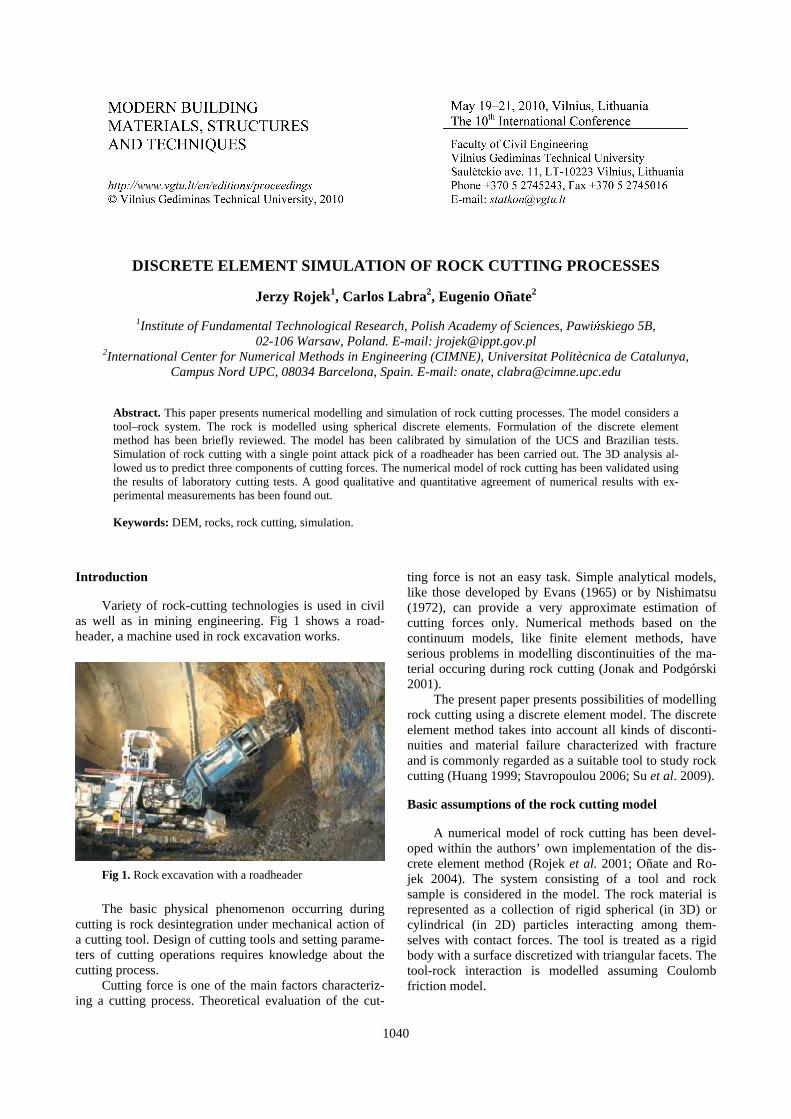
Variety of rock-cutting technologies is used in civil as well as in mining engineering. Fig 1 shows a road-header, a machine used in rock excavation works.
Fig 1. Rock excavation with a roadheader
The basic physical phenomenon occurring during
cutting is rock desintegration under mechanical action of a cutting tool. Design of cutting tools and setting parame-ters of cutting operations requires knowledge about the cutting process.
Cutting force is one of the main factors characteriz-ing a cutting process. Theoretical evaluation of the cut-
ting force is not an easy task. Simple analytical models, like those developed by Evans (1965) or by Nishimatsu (1972), can provide a very approximate estimation of cutting forces only. Numerical methods based on the continuum models, like finite element methods, have serious problems in modelling discontinuities of the ma-terial occuring during rock cutting (Jonak and Podgórski 2001).
The present paper presents possibilities of modelling rock cutting using a discrete element model. The discrete element method takes into account all kinds of disconti-nuities and material failure characterized with fracture and is commonly regarded as a suitable tool to study rock cutting (Huang 1999; Stavropoulou 2006; Su et al. 2009).
Basic assumptions of the rock cutting model
A numerical model of rock cutting has been devel-oped within the authors’ own implementation of the dis-crete element method (Rojek et al. 2001; Oñate and Ro-jek 2004). The system consisting of a tool and rock sample is considered in the model. The rock material is represented as a collection of rigid spherical (in 3D) or cylindrical (in 2D) particles interacting among them-selves with contact forces. The tool is treated as a rigid body with a surface discretized with triangular facets. The tool-rock interaction is modelled assuming Coulomb friction model.
1041
Discrete element method formulation
The translational and rotational motion of the i-th discrete element is governed by the standard equations of the rigid body dynamics:
iiim Fu =&& (1)
iiiJ Mω =& (2)
where u is the element centroid displacement in a fixed (inertial) coordinate frame X, ω– the angular velocity, m– the element mass, J– the moment of inertia, F– the resul-tant force, and M– the resultant moment about the central axes. Vectors F and T are sums of all forces and moments applied to the i-th element due to external load, contact interactions with neighbouring spheres and other obstacles, as well as forces resulting from damping in the system. The form of the rotational equation (2) is valid for spheres and cylinders (in 2D) and is simplified with respect to a general form for an arbitrary rigid body.
Equations of motion (1) and (2) are integrated in time using the central difference scheme. The time inte-gration operator for the translational motion at the n-th time step is as follows:
i
nin
i m
Fu =&& (3)
tni
ni
ni Δ+=
−+ uuu &&&&
2/12/1 (4)
tni
ni
ni Δ+=
+−+ 2/111 uuu & (5)
The first two steps in the integration scheme for the rotational motion are identical to those given by equa-tions (3) and (4):
i
nin
i J
Mω =& (6)
tni
ni
ni Δ+=
−+
ωωω &
2/12/1 (7)
The vector of incremental rotation 1+Δ
niθ is calcu-
lated as:
tni
ni Δ=Δ
++ 2/11ωθ (8)
If necessary it is also possible to track the total change of rotational position of particles.
Explicit integration in time yields high computa-tional efficiency of the solution for a single step. The disadvantage of the explicit integration scheme is its con-ditional numerical stability imposing the limitation on the time step tΔ . The time step tΔ must not be larger than a critical time step crtΔ
crtt Δ≤Δ (9)
determined by the highest natural frequency of the system
maxω
max
cr2
ω
=Δt (10)
Exact determination of the highest frequency ωmax would require solution of the eigenvalue problem defined for the whole system of connected rigid particles. In an approximate solution procedure adopted, the maximum frequency is estimated as the maximum of natural fre-quencies of the mass–spring systems defined for the con-tact pairs of particles.
The overall behaviour of the system is determined by the cohesive/frictional contact models assumed for the interaction between contacting spheres. The contact force between two particles F can be decomposed into the normal and tangential components, Fn and FT , respec-tively
TnTn F FnFFF +=+= (11)
where n is the unit vector normal to the particle surface at the contact point.
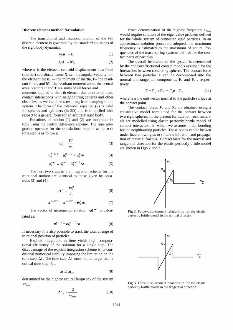
The contact forces Fn and FT are obtained using a constitutive model formulated for the contact between two rigid spheres. In the present formulation rock materi-als are modelled using elastic perfectly brittle model of contact interaction, in which we assume initial bonding for the neighbouring particles. These bonds can be broken under load allowing us to simulate initiation and propaga-tion of material fracture. Contact laws for the normal and tangential direction for the elastic perfectly brittle model are shown in Figs 2 and 3.
Fig 2. Force–displacement relationship for the elastic perfectly brittle model in the normal direction
Fig 3. Force–displacement relationship for the elastic perfectly brittle model in the tangential direction

1042
When two particles are bonded the contact forces in both normal and tangential directions are calculated from the linear constitutive relationships:
nnn ukF = (12)
TTT k uF = (13)
where kn and kT are the interface stiffness in the normal and tangential directions, and un and uT– the normal and tangential relative displacements, respectively.
The tensile and shear contact forces are limited by the tensile and shear interface strengths, Rn and RT, re-spectively:
nn RF ≤ (14)
TT R≤F (15)
Cohesive bonds are broken instantaneously when the interface strength is exceeded either by the tangential contact force or by the tensile contact force. After debonding the elements can interact according to the frictional contact conditions without cohesion. Similarly the fricitional contact is assumed for the tool-rock inter-action
Determination of rock model parameters
Determination of the model parameters is the first step in the discrete element simulation of rock cutting process. A set of micromechanical parameters yielding required macroscopic rock properties has been deter-mined using the methodology developed by Huang (1999) based on the combination of the dimensional analysis with numerical simulation of the standard labora-tory tests for rocks, unconfined compression test (Fig 4) and Brazilian test (Fig 5). The stress-strain relationship obtained in the numerical simulation of the unconfined compression test is shown in Fig 6. It is similar to the stress-strain curves obtained in laboratory. The force–time curve obtained in the simulation of the Brazilian test is plotted in Fig 7. These curves allow us to determine macroscopic properties of the material modelled with the discrete element method.
Fig 4. Results of the numerical simulation of the un-confined compression test
Fig 5. Results of the numerical simulation of the Bra-zilian test
Fig 6. Simulation of the unconfined compression test: stress–strain curve
Fig 7. Simulation of the Brazilian test: force–time curve
Simulation of rock cutting with a roadheader pick
Validation of the rock cutting model has been car-ried using experimental results obtained in a laboratory test performed in the laboratory of Sandvik Mining and Construction (Fig 8). The tests consisted in cutting of a sandstone block with a rotating roadheader pick. Me-chanical properties of the rock have been determined experimentally and are the following: Young modulus E = 18690 MPa, Poisson ratio ν = 0.23, compressive strength σc = 127 MPa and tensile strength σt = 12 MPa.

1043
The test has been analysed using a three dimensional discrete element model. Rock sample has been discre-tized using 71,200 spherical particles. For the rock con-sidered the following set of micromechanical parameters has been found for the DEM model: contact stiffness in the normal direction kn = 5.4·106 N/m, contact stiffness in the tangential direction kT = 2.16·106 N/m, cohesive bond strengths in the normal and tangential direction, Rn = RT = 86 N. The results of numerical simulation are shown in Fig 9. Splitting of chips typical for brittle rock cutting can be seen.
Fig 8. Laboratory rock cutting test (courtesy of Sand-vik Mining and Construction GmbH, Zeltweg, Aus-tria)
Fig 9. Numerical simulation of the rock cutting test
The three components of cutting forces obtained in
simulation are plotted in Fig 10. Numerical forces are compared with experimental average measurements. Quite a good agreement can be observed.
Fig 10. Rock cutting forces– comparison of numerical results with experimental average values
Simulation of rock cutting with a TBM disc cutter
Tunnel Boring Machine (TBM) is used in tunnel ex-cavation. TBMs perform rock cutting with disc cutters mounted on a cutterhead. The linear cutting test has been established to predict TBM performance. The linear cut-ting test has been simulated. Fig 11 shows the simulation results. The granite properties are assumed in the simula-tion, appropriate DEM parameters being evaluated. Fig 12 shows the normal cutting force history. Numerical results have been compared with experimental ones pro-vided by Herrenknecht AG. A good agreement between the numerical and average experimental values is clearly seen.
Fig 11. Simulation of rock cutting with a TBM disc cutter

1044
Fig 12. Simulation of rock cutting with a TBM disc cutter– comparison of numerical
cutting forces with experimental average values
Concluding remarks
The three-dimensional discrete element model of rock cutting is capable to represent correctly complexity of a rock cutting process. A good qualitative and quanti-tative agreement of numerical results with experimental measurements has been found out in the validation of the model developed in the present work. The 3D model developed can be employed in the design of rock cutting tools and processes.
Acknowledgments
The authors acknowledge partial funding by the EU project TUNCONSTRUCT (contract no. IP 011817-2). Special thanks are given to Hubert Kargl and Jan Aker-man from Sandvik Mining and Construction GmbH, Zeltweg, Austria, and Karin Bäppler and Florian Köppl from Herrenknecht AG, for providing experimental re-sults and sharing their engineering experience with the authors.
References
Evans, I. 1965. The force required for pointed attack picks, Int. J. Min. Engng. 2: 63–71. doi:10.1007/BF00880858
Huang, H. 1999. Discrete Element Modeling of Tool-Rock In-teraction. PhD Thesis. University of Minnesota.
Jonak, J.; Podgórski, J. 2001. Mathematical model and results of rock cutting modelling, Journal of Mining Science 37: 615–618. doi:10.1023/A:1016034805831
Nishimatsu, Y. 1972. The mechanics of rock cutting, Int. J. Rock Mech. Mining Sci. 9: 261–270. doi:10.1016/0148-9062(72)90027-7
Oñate, E.; Rojek, J. 2004. Combination of discrete element and finite element methods for dynamic analysis of geome-chanics problems, Comput. Meth. Appl. Mech. Eng. 193: 3087–3128. doi:10.1016/j.cma.2003.12.056
Rojek, J.; Oñate, E.; Zarate, F.; Miquel, J. 2001. Modelling of rock, soil and granular materials using spherical elements, in Proc. of the 2nd European Conference on Computa-tional Mechanics ECCM-2001, Cracow, Poland, 26-29 June 2001.
Stavropoulou, M. 2006. Modeling of small-diameter rotary drilling tests on marbles, Int. J. Rock Mech. Mining Sci. 43: 1034–1051. doi:10.1016/j.ijrmms.2006.03.008
Su, O.; Akcin, N. A.; te Kamp, L. 2009. Modeling of Cutting Forces Acting on a Conical Pick, in Proc. of EURO:TUN 2009 II International Conference on Computational Methods in Tunnelling, Bochum, Germany.