Discrete Component Phono PreAmp - amstzone.org · Discrete Component Phono PreAmp The input is...
7
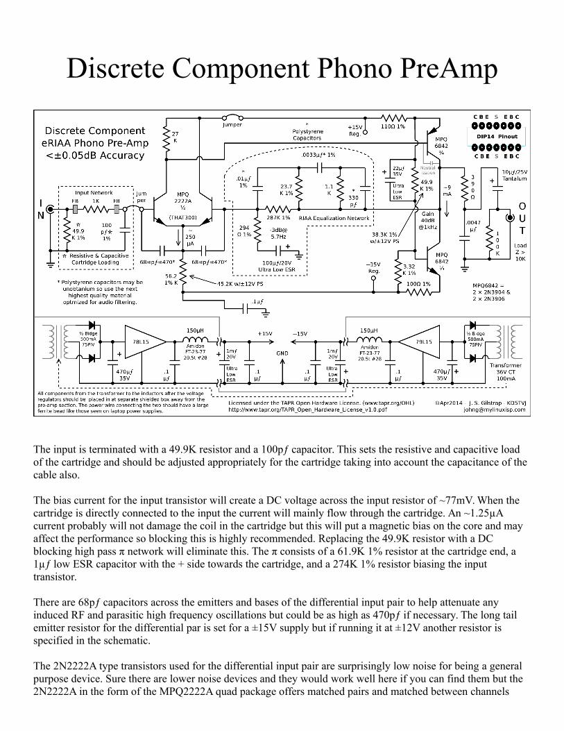
Discrete Component Phono PreAmp The input is terminated with a 49.9K resistor and a 100pƒ capacitor. This sets the resistive and capacitive load of the cartridge and should be adjusted appropriately for the cartridge taking into account the capacitance of the cable also. The bias current for the input transistor will create a DC voltage across the input resistor of ~77mV. When the cartridge is directly connected to the input the current will mainly flow through the cartridge. An ~1.25µA current probably will not damage the coil in the cartridge but this will put a magnetic bias on the core and may affect the performance so blocking this is highly recommended. Replacing the 49.9K resistor with a DC blocking high pass π network will eliminate this. The π consists of a 61.9K 1% resistor at the cartridge end, a 1µƒ low ESR capacitor with the + side towards the cartridge, and a 274K 1% resistor biasing the input transistor. There are 68pƒ capacitors across the emitters and bases of the differential input pair to help attenuate any induced RF and parasitic high frequency oscillations but could be as high as 470pƒ if necessary. The long tail emitter resistor for the differential par is set for a ±15V supply but if running it at ±12V another resistor is specified in the schematic. The 2N2222A type transistors used for the differential input pair are surprisingly low noise for being a general purpose device. Sure there are lower noise devices and they would work well here if you can find them but the 2N2222A in the form of the MPQ2222A quad package offers matched pairs and matched between channels
Transcript of Discrete Component Phono PreAmp - amstzone.org · Discrete Component Phono PreAmp The input is...
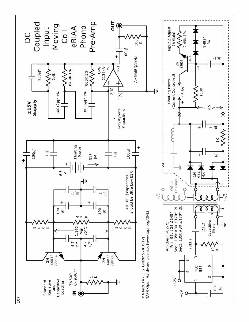
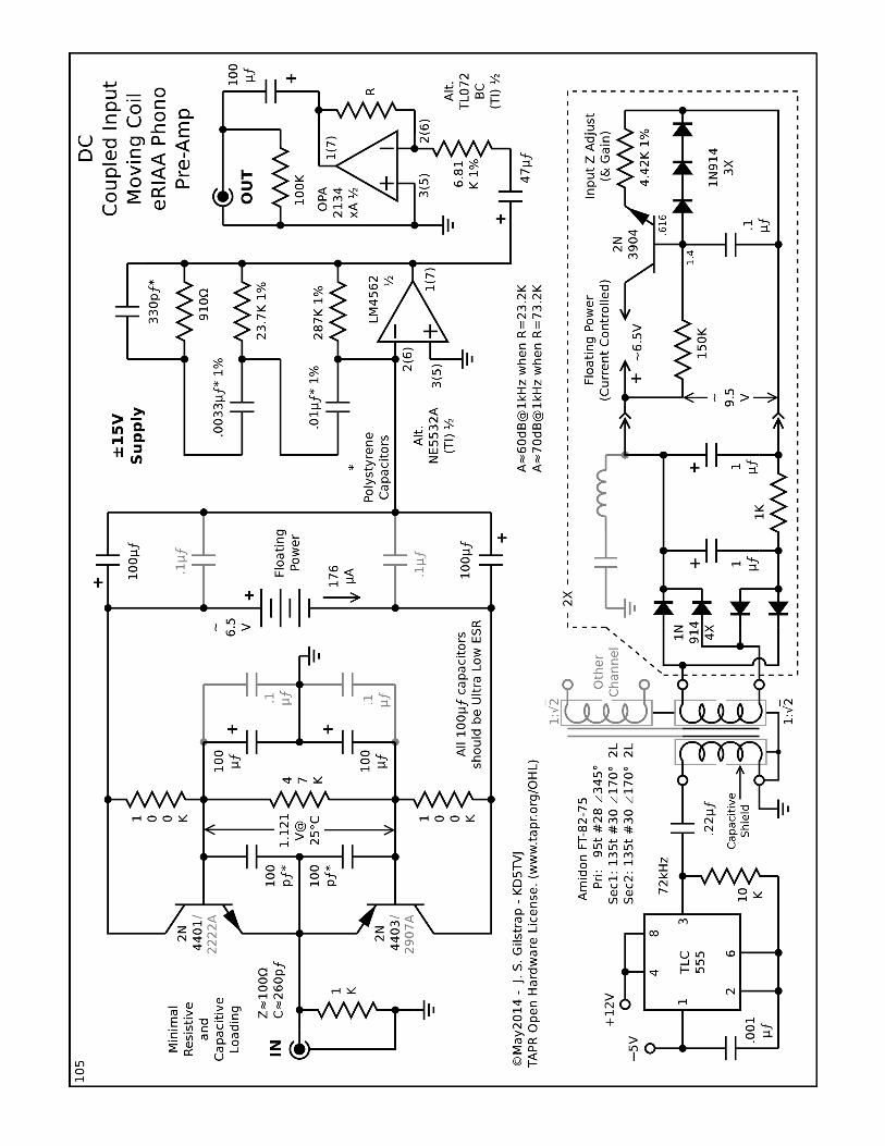
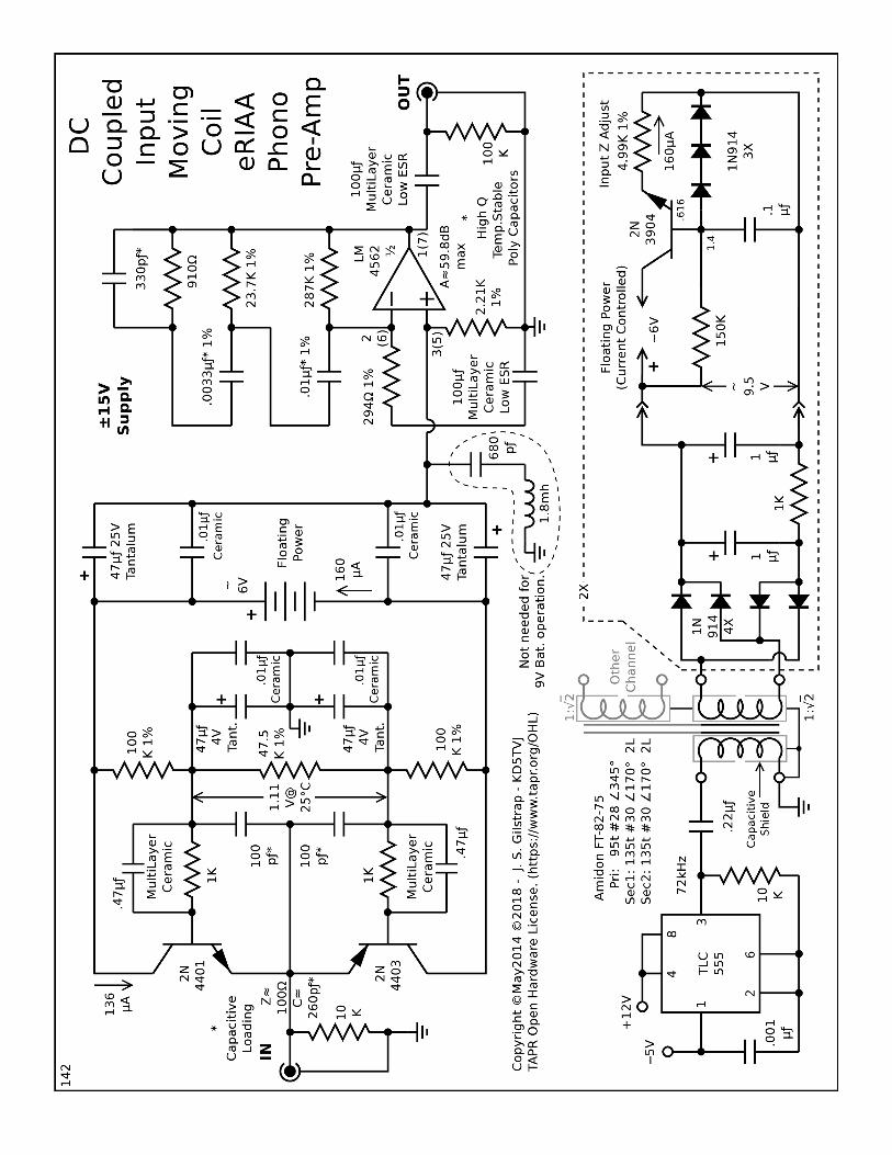
Discrete Component Phono PreAmp
The input is terminated with a 49.9K resistor and a 100pƒ capacitor. This sets the resistive and capacitive load of the cartridge and should be adjusted appropriately for the cartridge taking into account the capacitance of the cable also.
The bias current for the input transistor will create a DC voltage across the input resistor of ~77mV. When the cartridge is directly connected to the input the current will mainly flow through the cartridge. An ~1.25µA current probably will not damage the coil in the cartridge but this will put a magnetic bias on the core and may affect the performance so blocking this is highly recommended. Replacing the 49.9K resistor with a DC blocking high pass π network will eliminate this. The π consists of a 61.9K 1% resistor at the cartridge end, a 1µƒ low ESR capacitor with the + side towards the cartridge, and a 274K 1% resistor biasing the input transistor.
There are 68pƒ capacitors across the emitters and bases of the differential input pair to help attenuate any induced RF and parasitic high frequency oscillations but could be as high as 470pƒ if necessary. The long tail emitter resistor for the differential par is set for a ±15V supply but if running it at ±12V another resistor is specified in the schematic.
The 2N2222A type transistors used for the differential input pair are surprisingly low noise for being a general purpose device. Sure there are lower noise devices and they would work well here if you can find them but the 2N2222A in the form of the MPQ2222A quad package offers matched pairs and matched between channels
also. The 2N2222A has a max noise of 4dB and 0.8nV/√Hz. The MPQ2222A and its generic form NTE2321 arein DIP while the MMPQ2222A is a SMD device. THAT300 is available in both DIP and SMD but is much moreexpensive.
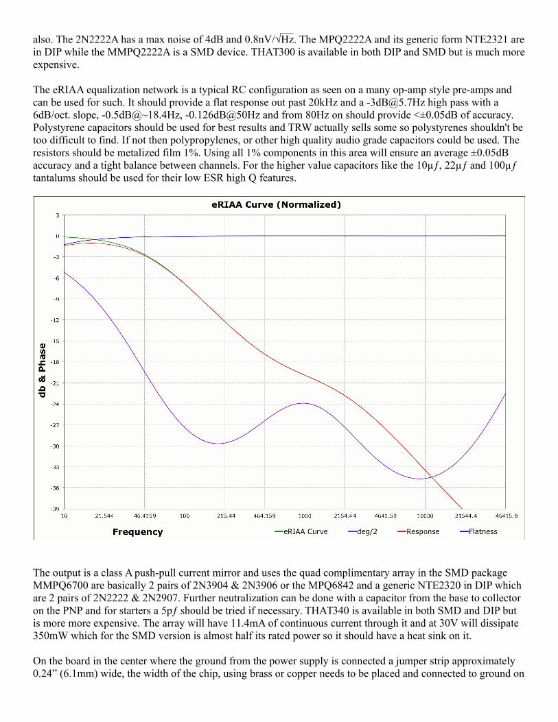
The eRIAA equalization network is a typical RC configuration as seen on a many op-amp style pre-amps and can be used for such. It should provide a flat response out past 20kHz and a [email protected] high pass with a 6dB/oct. slope, -0.5dB@~18.4Hz, -0.126dB@50Hz and from 80Hz on should provide <±0.05dB of accuracy. Polystyrene capacitors should be used for best results and TRW actually sells some so polystyrenes shouldn't be too difficult to find. If not then polypropylenes, or other high quality audio grade capacitors could be used. The resistors should be metalized film 1%. Using all 1% components in this area will ensure an average ±0.05dB accuracy and a tight balance between channels. For the higher value capacitors like the 10µƒ, 22µƒ and 100µƒ tantalums should be used for their low ESR high Q features.
The output is a class A push-pull current mirror and uses the quad complimentary array in the SMD package MMPQ6700 are basically 2 pairs of 2N3904 & 2N3906 or the MPQ6842 and a generic NTE2320 in DIP which are 2 pairs of 2N2222 & 2N2907. Further neutralization can be done with a capacitor from the base to collector on the PNP and for starters a 5pƒ should be tried if necessary. THAT340 is available in both SMD and DIP but is more more expensive. The array will have 11.4mA of continuous current through it and at 30V will dissipate 350mW which for the SMD version is almost half its rated power so it should have a heat sink on it.
On the board in the center where the ground from the power supply is connected a jumper strip approximately 0.24” (6.1mm) wide, the width of the chip, using brass or copper needs to be placed and connected to ground on
the component side running under the complementary output transistor array to the other end of the board to ground. This will provide a short low inductance path for the 100µƒ filter cap on the negative supply voltage to filter out the current modulations produced by the driver output circuit. This leaves the rest of the grounding system free of the heavier current fluctuations produced by the output circuit from being introduced into the input circuit. If the strip is the right thickness, 0.015” (0.4mm), then it will make physical contact with the bottom of the IC and function as a small heat sink.
It is good to keep the power supply separated and away from the pre-amp and placing it in a shielded box is thebest bet. The supply cable from the power supply to the pre-amp should have a large ferrite bead like a laptop supply to eliminate any stray interference from RF or other sources. Pulse Electronics has a 34V CT 125mA transformer part # PC-34-125B22 that could work for the power supply.
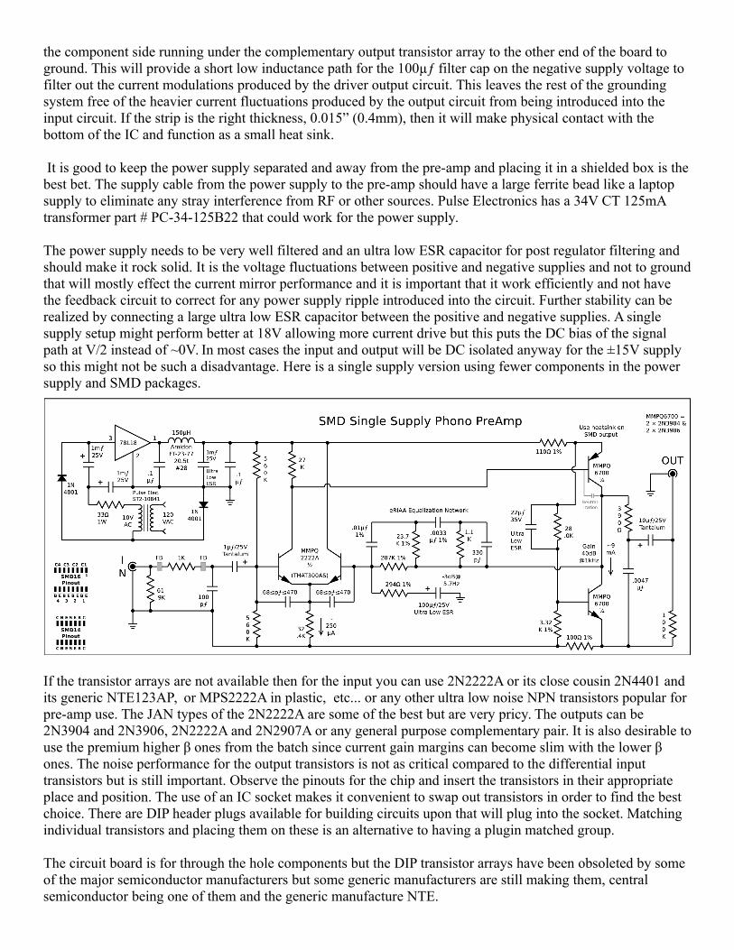
The power supply needs to be very well filtered and an ultra low ESR capacitor for post regulator filtering and should make it rock solid. It is the voltage fluctuations between positive and negative supplies and not to groundthat will mostly effect the current mirror performance and it is important that it work efficiently and not have the feedback circuit to correct for any power supply ripple introduced into the circuit. Further stability can be realized by connecting a large ultra low ESR capacitor between the positive and negative supplies. A single supply setup might perform better at 18V allowing more current drive but this puts the DC bias of the signal path at V/2 instead of ~0V. In most cases the input and output will be DC isolated anyway for the ±15V supply so this might not be such a disadvantage. Here is a single supply version using fewer components in the power supply and SMD packages.
If the transistor arrays are not available then for the input you can use 2N2222A or its close cousin 2N4401 and its generic NTE123AP, or MPS2222A in plastic, etc... or any other ultra low noise NPN transistors popular for pre-amp use. The JAN types of the 2N2222A are some of the best but are very pricy. The outputs can be 2N3904 and 2N3906, 2N2222A and 2N2907A or any general purpose complementary pair. It is also desirable touse the premium higher β ones from the batch since current gain margins can become slim with the lower β ones. The noise performance for the output transistors is not as critical compared to the differential input transistors but is still important. Observe the pinouts for the chip and insert the transistors in their appropriate place and position. The use of an IC socket makes it convenient to swap out transistors in order to find the best choice. There are DIP header plugs available for building circuits upon that will plug into the socket. Matching individual transistors and placing them on these is an alternative to having a plugin matched group.
The circuit board is for through the hole components but the DIP transistor arrays have been obsoleted by some of the major semiconductor manufacturers but some generic manufacturers are still making them, central semiconductor being one of them and the generic manufacture NTE.
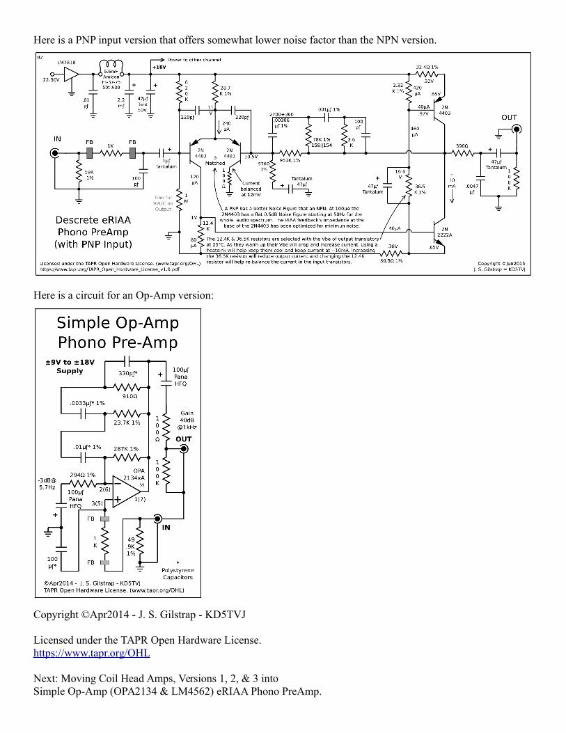
Here is a PNP input version that offers somewhat lower noise factor than the NPN version.
Here is a circuit for an Op-Amp version:
Copyright ©Apr2014 - J. S. Gilstrap - KD5TVJ
Licensed under the TAPR Open Hardware License.http s ://www.tapr.org/OHL
Next: Moving Coil Head Amps, Versions 1, 2, & 3 intoSimple Op-Amp (OPA2134 & LM4562) eRIAA Phono PreAmp.