Discharges to Groundwater - County Roscommon
130
Discharges to Groundwater Application Form Local Authority Services National Training Group (WSTG) August 2011 Revision B
Transcript of Discharges to Groundwater - County Roscommon

Discharges to Groundwater
Application Form
Local Authority Services National Training Group
(WSTG) G
August 2011
Revision B


Doc. Nr. : 252544/N/R/15/B
252544 N R 09 A
P:\Cork\DESIGN\projects\252544 - WSNTG Guidance & Training\Training Course - Task 8\Courseware\Guidance
Manual\Guidance 04.11.03.doc 03 November 2009
Licensing of discharges to Groundwater by Local Authorities
Local Authority Services National Training Group
August 2011
Monastery Road, Roscrea, Co. Tipperary


The complete set of documents in support of the Guidance, Procedures and Training on the Licensing of
Discharges to Surface Waters, Groundwater and to Sewer for Local Authorities consists of two volumes as
follows:
Volume 1 – Technical Guidance Manual:
Provides guidance to local Authorities on the licensing of discharges to surface waters, groundwaters, and
to sewers in accordance with the Local Government (Water Pollution) Acts 1977 - 2007.
Volume 2 – Application Forms & Applicant Guidance:
Provides a template application form to be used when applying for a licence to discharge to surface
waters;
Provides guidance to an applicant on applying for a licence to discharge to surface waters;
Provides a template application form to be used when applying for a licence to discharge to
groundwater;
Provides guidance to an applicant on applying for a licence to discharge to groundwater;
Provides a template application form to be used when applying for a licence to discharge to sewer;
Provides guidance to an applicant on applying for a licence to discharge to sewer;
This document is Volume 2 of the guidance documents.
Electronic copies of the Application forms are available to download from
http://www.wsntg.ie/publications/index.asp


Content Chapter Title Page
Glossary of Terms i
Application Form – Discharge to Groundwater 10

i
The following provides a glossary of terms used in this document. The definitions therein are not to be
taken as comprehensive but solely as an aid to the non-technical reader.
Abstraction
In relation to water contained in any source of water, means the doing of anything whereby any of that
water is removed from that source of water, whether temporarily or permanently, including anything
whereby the water is so removed for the purpose of being transferred to another source of water (Source:
Water Services Act, 2007)
Agreed Limit of Detection
The lowest concentration or quantity of a substance that can be distinguished from the absence of that
substance. It should be agreed between the regulator and the applicant.
Appropriate Assessment
In accordance with Article 6(3) of the Habitats Directive (92/43/EEC), an Appropriate Assessment is an
evaluation of the potential impacts of a plan or project on the conservation objectives of a Natura 2000 site
(European network of special areas of conservation and special protection areas), and the development,
where necessary, of mitigation or avoidance measures to mitigate negative effects.
Aquifer
A subsurface layer or layers of rock, or other geological strata, of sufficient porosity and permeability to
allow either a significant flow of groundwater or the abstraction of significant quantities of groundwater
(Groundwater Regulations, 2010).
Attenuation
A decrease in pollutant concentrations, flux, or toxicity as a function of physical, chemical and/or biological
processes, individually or in combination, in the subsurface environment. Attenuation processes include
dilution, dispersion, filtration, sorption, decay, and retardation.
Authorised person
A person appointed in writing by the Minister or by a Water Services Authority / Local Authority for the
purposes of enforcing the legislation under which they have been appointed.
Capacity
A measure of the ability of groundwater to assimilate or absorb pollutants whilst still maintaining acceptable
water quality in relation to applicable groundwater quality standards. The term relates primarily to the
chemical status of a groundwater body.
Coastal Water
The area of surface water on the landward side of a line, every point of which is at a distance of one
nautical mile on the seaward side from the nearest point of the baseline from which the breadth of territorial
waters is measured, extending where appropriate to the outer limit of transitional waters.
Compliance Point
The point (location, depth) at which a compliance value should be met. Generally it is represented by a
borehole or monitoring well from which representative groundwater samples can be obtained
Glossary of Terms
ii
Compliance Value
The concentration of a substance and associated compliance regime that, when not exceeded at the
compliance point, will prevent pollution and/or achieve water quality objectives at the receptor.
Conceptual Hydrogeological Model
A simplified representation or working description of how a real hydrogeological system is believed to
behave on the basis of qualitative analysis of desk study information, field observations and field data. A
quantitative conceptual model includes preliminary calculations of water balances, including groundwater
flow.
Conservative Pollutants
Pollutants which do not readily or easily react or biodegrade in the subsurface environment.
Contaminant (Chemical) Load
The volume and concentrations of chemical substances (pollutants) discharged to soil or groundwater.
Diffuse Sources
Diffuse sources of pollution are spread over wider geographical areas rather than at individual point
locations. Diffuse sources include general land use activities and landspreading of industrial, municipal
wastes and agricultural organic and inorganic fertilisers.
Direct Input
An input to groundwater that bypasses the unsaturated zone (e.g. direct injection through a borehole) or is
directly in contact with the groundwater table in an aquifer either year round or seasonally.
Domestic Waste Water
Waste water of a composition and concentration (biological and chemical) normally discharged by a
household, and which originates predominantly from the human metabolism or from day to day domestic
type human activities, including washing and sanitation, but does not include fats, oils, grease or food
particles discharged from a premises in the course of, or in preparation for, providing a related service or
carrying on a related trade. (Water Services Act, 2007).
Downgradient
The direction of decreasing groundwater levels, i.e. flow direction. Opposite of upgradient.
Dry Weather Flow (Effluent)
For a waste water treatment plant, the Dry Weather Flow is the average daily flow to the plant without any
contribution from stormwater inflow or infiltration of groundwater into the waste water collection system.
Dry Weather Flow (Receiving Water)
The Dry Weather Flow of a stream or river is the annual minimum daily mean flow rate with a return period
of 50 years. The Dry Weather Flow is a statistical measure of low flow and usually requires reliable long
term low flow data or sufficient information that would allow the estimation of the Dry Weather Flow.
Environmental Quality Standard (EQS)
The concentration of a particular pollutant or group of pollutants in a receiving water which should not be
exceeded in order to protect human health and the environment.
Good Groundwater Chemical Status
The chemical status of a body of groundwater which meets all the conditions for good chemical status set
out in Groundwater Regulations 2010, regulations 39 to 43.
iii
Good Groundwater Status
Achieved when both the quantitative and chemical status of a groundwater body are good.
Good Surface Water Chemical Status
The chemical status of a body of groundwater which meets all the conditions for good chemical status set
out in the Surface Water Regulations 2009, S.I. No. 272 of 2009.
Good Surface Water Status
Achieved when both the quantitative and chemical status of a surface water body are good.
Groundwater
All water which is below the surface of the ground in the saturation zone and in direct contact with the
ground or subsoil (Groundwater Regulations, 2010). The EPA interpretation of the settings in which
groundwater can occur is presented in Section 3.2.1.
Groundwater Body (GWB)
A volume of groundwater defined as a groundwater management unit for the purposes of reporting to the
European Commission under the Water Framework Directive. Groundwater bodies are defined by aquifers
capable of providing more than 10 m3 per day, on average, or serving more than 50 persons.
Groundwater Dependent Terrestrial Ecosystems (GWDTEs)
These are groundwater dependent wetlands, whereby the dependency is either on groundwater flow, level
or chemistry as the controlling factors or qualifying interests of associated habitats. Examples are raised
bogs, alkaline fens and turloughs. Groundwater dependent terrestrial ecosystems are listed on the EPA’s
register of protected areas in accordance with Regulation 8 of the Water Policy Regulations, 2003.
Groundwater Protection Scheme (GWPS)
A scheme comprising two principal components: a land surface zoning map which encompasses the
hydrogeological elements of risk (of pollution); and a groundwater protection response matrix for different
potentially polluting activities (DELG/EPA/GSI, 1999).
Groundwater Protection Responses (GWPR)
Control measures, conditions or precautions recommended as a response to the acceptability of an activity
within a groundwater protection zone.
Groundwater Protection Zone (GPZ)
A zone delineated by integrating aquifer categories or source protection areas and associated vulnerability
ratings. The zones are shown on a map, each zone being identified by a code, e.g. SO/H (outer source
area with a high vulnerability) or Rk/E (regionally important karstified aquifer with an extreme vulnerability).
Groundwater protection responses are assigned to these zones for different potentially polluting activities.
Groundwater Recharge
Two definitions: a) the process of rainwater or surface water infiltrating to the groundwater table; b) the
volume (amount) of water added to a groundwater system.
Groundwater Resource
An aquifer capable of providing a groundwater supply of more than 10 m3 a day as an average or serving
more than 50 persons.
Hazardous Substances
Substances or groups of substances that are toxic, persistent and liable to bio-accumulate, and other
substances or groups of substances which give rise to an equivalent level of concern. A list of hazardous
substances has been published by the EPA (2010a).

iv
Hydraulic Conductivity
The rate at which water can move through a unit volume of geological medium under a potential unit
hydraulic gradient. The hydraulic conductivity can be influenced by the properties of the fluid, including its
density, viscosity and temperature, as well as by the properties of the soil or rock.
Hydraulic Gradient
The change in total head of water with distance; the slope of the groundwater table or the piezometric
surface.
Indirect Input
An input to groundwater where the pollutants infiltrate through soil, subsoil and/or bedrock to the
groundwater table.
Input
The direct or indirect introduction of pollutants into groundwater as a result of human activity.
Integrated Constructed Wetlands (ICWs)
Constructed wetlands are artificially constructed or modified wetland systems supporting vegetation, which
provide secondary treatment, by physical and biological means, to effluent from a primary treatment step.
Constructed wetlands may also be used for tertiary treatment (EPA, 2009a). “Integrated constructed
wetlands” have been developed in Ireland to integrate water quality, management of landscape-fit towards
improving site aesthetics and enhancement of biodiversity. ICWs can primarily treat domestic waste water
and farmyard soiled water. Guidance (DEHLG, 2010) is available that outlines the ICW concept, and
provides information on site assessment, design, construction, operation, maintenance and monitoring.
Integrated Pollution Prevention and Control (IPPC) Licence
A licence for industrial and other activities issued by the EPA under the Environmental Protection
Agency Acts, 1992 to 2011.
Karst
A distinctive landform characterised by features such as surface collapses, sinking streams, swallow holes,
caves, turloughs and dry valleys, and a distinctive groundwater flow regime where drainage is largely
underground in solutionally enlarged fissures and conduits.
Lake
A body of surface water, which may be artificial or natural.
Landfill
A waste disposal site or facility used for the deposit of waste onto or under land.
Licence Application
An application to a Local Authority or a Water Services Authority for a licence to discharge trade or sewage
effluent to waters or to sewer
Licensing Authority
Includes the Water Services Authority (as defined in the Water Services Act, 2007) and the Local Authority
(as defined in the Local Government Act, 2001) which includes County Councils and City Councils.
Limit Objective
This objective requires the implementation of all measures necessary to limit inputs of non-hazardous
substances, into groundwater to ensure that such inputs do not cause deterioration in status or significant
and sustained upward trends in their concentrations in groundwater.

v
Limit Value
The mass, expressed in terms of a specific parameter, concentration or level of an emission, or both a
specific concentration and level of an emission, that may not be exceeded during one or more periods of
time. In this guidance, when not exceeded at the source, the limit value will prevent an unacceptable
release to groundwater.
Minimum Reporting Value (MRV)
The lowest concentration of a substance that can be determined with a given degree of confidence using
commonly available analytical methods, primarily used in the context of hazardous substances. MRVs are
not necessarily equivalent to limits of detection.
Non-hazardous Substances
Pollutants listed in Schedule 2 of the Groundwater Regulations 2010 that are not considered hazardous, as
well as any other non-hazardous pollutants not listed in Schedule 2 but presenting an existing or potential
risk of pollution. Non-hazardous substances are listed in a document by the EPA (2010a).
On-site Waste Water Treatment Systems (OSWTSs)
A generic term for small-scale waste water treatment systems associated with single houses and small
communities or facilities, and mostly associated with septic tanks and intermittent filter systems offering
secondary treatment of raw waste water effluent.
Pathway
The route which a particle of water and/or chemical or biological substance takes through the environment
from a source to a receptor location. Pathways are determined by natural hydrogeological characteristics
and the nature of the contaminant, but can also be influenced by the presence of features resulting from
human activities (e.g., abandoned ungrouted boreholes which can direct surface water and associated
pollutants preferentially to groundwater).
Permeability
A measure of a soil or rock’s ability or capacity to transmit water under a potential hydraulic gradient
(synonymous with hydraulic conductivity).
Point Source
Any discernible, confined or discrete conveyance from which pollutants are or may be discharged. These
may exist in the form of pipes, ditches, channels, tunnels, conduits, containers, and sheds, or may exist as
distinct percolation areas, integrated constructed wetlands, or other surface application of pollutants at
individual locations. Examples are discharges from waste water works and effluent discharges from
industry.
Polluting Matter
Any substance liable to cause pollution, and, for the purpose of this definition, ‘substance’ includes bacteria
and other pathogens, where relevant, and the expression "polluting matter" shall be construed accordingly.
(Source European Communities Environmental Objectives (Surface Waters) Regulations, 2009).
Pollution
The direct or indirect introduction, as a result of human activity, of substances or heat into the air, water or
land which may be harmful to human health or the quality of aquatic ecosystems or terrestrial ecosystems
directly depending on aquatic ecosystems which result in damage to material property, or which impair or
interfere with amenities and other legitimate uses of the environment (Groundwater Regulations, 2010).

vi
Poorly Productive Aquifers (PPAs)
Low-yielding bedrock aquifers that are generally not regarded as important sources of water for public
water supply but that nonetheless may be important in terms of providing domestic and small community
water supplies and of delivering water and associated pollutants to rivers and lakes via shallow
groundwater pathways.
Population Equivalent (p.e.)
A conversion value which aims at evaluating non-domestic pollution in reference to domestic pollution fixed
by EEC directive (Urban Waste Water Treatment Directive 91/271/EEC) at 60 g/day BOD5.
Pore water
Water that occupies void spaces between mineral grains in unlithified (uncemented) sediments.
Preferential Flow
A generic term used to describe water movement along favoured pathways through a geological medium,
bypassing other parts of the medium. Examples include pores formed by soil fauna, plant root channels,
weathering cracks, fissures and/or fractures.
Prevent Objective
Taking all measures necessary and reasonable to avoid the entry of hazardous substances into
groundwater and to avoid any significant increase in their concentration in groundwater.
Priority Substances
Those substances or groups of substances, identified by the Commission in accordance with Article 16(2)
of the Water Framework Directive and listed in Tables 11 and 12 of Schedule 6 of the European
Communities Environmental Objectives (Surface Waters) Regulations, 2009 that have been prioritised for
action by the setting of environmental quality standards at Community level.
Priority Hazardous Substances
Those substances or groups of substances forming a subset of priority substances identified by the
Commission in accordance with Article 16(3) of the Water Framework Directive and for which measures
have to be taken to cease or phase-out discharges, losses and emissions and which are listed in Table 12
of Schedule 6 of the European Communities Environmental Objectives (Surface Waters) Regulations,
2009.
Receptor-based Water Quality Standards
Standards developed to protect receptors, which include drinking water standards, environmental quality
standards for surface waters and minimum reporting values. They are used to develop compliance values
for assessing inputs to groundwater.
Receptors
Receptors are existing and potential future groundwater resources, drinking water supplies (e.g. springs
and abstraction wells), surface water bodies into which groundwater discharges (e.g. streams) and
groundwater dependent terrestrial ecosystems (GWDTEs).
Regulator
In this document, the EPA or the relevant local authority depending on the type of discharge licence and
location.
River
A body of inland water flowing for the most part on the surface of the land but which may flow underground
for part of its course (Groundwater Regulations, 2010). Upland rivers are generally fast flowing and lowland
rivers are generally slow flowing and meandering.

vii
River Basin
The area of land from which all surface water run-off flows, through a sequence of streams, rivers and
lakes, into the sea at a single river mouth, estuary or delta.
River Basin District (RBD)
A group of river basins formally defined by Water Policy (2003) for the purposes of reporting Water
Framework Directive requirements to the European Commission.
River Basin Management Plan (RBMP)
A detailed document describing the characteristics of a river basin district, the environmental objectives
that need to be achieved, and the pollution control measures required to achieve these objectives through
a specified work programme.
Saturated Zone
The zone below the water table in an aquifer in which all pores and fissures and fractures are filled with
water at a pressure that is greater than atmospheric.
Section 4 Licence
A licence to discharge to waters, given by local authorities under the Local Government (Water Pollution)
Acts 1977 to 1990.
Section 16 Licence
A licence to discharge to sewer, given by local authorities under the Local Government (Water Pollution)
Acts 1977 to 1990.
Sewer
Drainage pipes and sewers of every description, including storm water sewers, owned by, vested in or
controlled by a water services authority, an authorised provider of water services or a person providing
water services jointly with or on behalf of a water services authority or an authorised provider of water
services, but does not include a drain or service connection (Source: Water Services Act, 2007)
Sewage Effluent
Effluent from any works, apparatus, plant or drainage pipe used for the disposal to waters of sewage,
whether treated or untreated (Source: Local Government (Water Pollution) Act 1977)
Significant and Sustained Upward Trend
Any statistically and environmentally significant increase in concentration of a pollutant, group of pollutants,
or indicator of pollution in groundwater (EPA, 2010b).
Soil (topsoil)
The uppermost layer of soil in which plants grow.
Source Pathway Receptor (SPR) Model
A SPR model involves identifying whether and how pollution sources are connected to a receptor via a
pathway. A conceptual model provides an understanding of all the relationships between SPR factors in a
particular hydrogeological setting.
Source Protection Area
The catchment area around a groundwater source which contributes water to that source (Zone of
Contribution), divided into two areas; the Inner Protection Area (SI) and the Outer Protection Area (SO).
The SI is designed to protect the source against the effects of human activities that may have an
immediate effect on the source, particularly in relation to microbiological pollution. It is defined by a 100-

viii
day time of travel (TOT) from any point below the water table to the source. The SO covers the remainder
of the zone of contribution of the groundwater source.
Special Areas of Conservation (SACs)
Areas selected and designated under the Natural Habitats Regulations, 1997 (as amended in 1998 and
2005) for the protection of certain habitats and species.
Storm Water
Runoff of rainwater mainly in urban settings during high intensity rainfall events. Stormwater may enter and
discharge to groundwater or other receptors through storm drains.
Subsoil
Unlithified (uncemented) geological strata or materials beneath the topsoil and above bedrock.
Surface Water
A discrete and significant element of surface water such as a lake, reservoir, stream, river or canal, part of
a stream, river or canal, a transitional water or a stretch of coastal water. (European Communities
Environmental Objectives (Surface Waters) Regulations, 2009)
Surface Water Bodies
Inland waters, except groundwater, which are on the land surface (such as reservoirs, lakes, rivers,
transitional waters, coastal waters and, under some circumstances, territorial waters) and which occur
within a WFD River Basin District.
Sustainable Urban Drainage Systems (SuDS)
Generic term used to describe conveyance systems and control structures designed to intercept, manage,
and dispose of surface drainage and stormwater in urban settings and the built environment. Components
of SuDS may include drains, ponds, soakaways, recharge basins, and porous pavements.
Threshold Values (TVs)
Chemical concentration values for substances listed in Schedule 5 of the Groundwater Regulations (2010),
which are used for the purpose of chemical status classification of groundwater bodies.
Trade Effluent
Effluent from any works, apparatus, plant or drainage pipe used for the disposal to a waste water works of
any liquid (whether treated or untreated), either with or without particles of matter in suspension therein,
which is discharged from premises used for carrying on any trade or industry (including mining), but does
not include domestic waste water or storm water (Water Services Act, 2007).
Transitional Waters
Bodies of surface water in the vicinity of river mouths which are partly saline in character as a result of their
proximity to saline coastal waters, and which are substantially influenced by freshwater flows.
Trigger Level
A parameter value specified in a licence or authorisation, the achievement or exceedance of which
requires certain actions to be taken by the licensee.
UK TAG
The United Kingdom Technical Advisory Group, a partnership of UK environment and conservation
agencies set up to interpret and support the implementation of the Water Framework Directive. The EPA is
an invited member of the UK TAG.

ix
Unacceptable Input to Groundwater
An input of hazardous substances to groundwater, or pollution resulting from an input of non-hazardous
substances to groundwater, where these inputs are not exempted by the provisions of Regulation 14 of the
Groundwater Regulations (2010).
Unsaturated Zone
The zone between the land surface and the water table, in which pores, fractures and fissures are only
partially filled with water. Also known as the vadose zone.
Vulnerability
The intrinsic geological and hydrogeological characteristics that determine the ease with which
groundwater may be contaminated by human activities (Fitzsimmons et al, 2003).
Waste Licence
A licence for activities in the waste sector given by the EPA under the Waste Management Acts, 1996 to
2010.
Waste Water Effluent
Any quantity or volume of waste water generated from a domestic, industrial, or commercial facility.
Typically disposed of via an onsite waste water treatment system or a specially designed treatment facility
such as a waste water treatment plant.
Waste Water Discharge Licence or Certificate of Authorisation
Issued by the EPA to sanitary authorities under the Waste water Discharge (Authorisation) Regulations
2007 and 2011.
Water Body
A WFD management unit. It refers to all types of waters, including surface water bodies, transitional and
coastal water bodies, as well as groundwater bodies.
Water Table
The uppermost level of saturation in an aquifer at which the pressure is atmospheric.
Water Pollution
The discharge by man, directly or indirectly, of substances or energy into the aquatic environment, the
results of which are such as to cause hazards to human health, harm to living resources and to aquatic
ecosystems, damage to amenities or interference with other legitimate uses of water.
Water Services Authority
Includes a County Council or a City Council as defined in the Local Government Act, 2001, (sanitary
authority or local authority).
Zone of Contribution (ZOC)
The area surrounding a pumped well or spring that encompasses all areas or features that supply
groundwater to the well or spring. It is defined as the area required to support an abstraction and/or
overflow (in the case of springs) from long-term groundwater recharge

10
Local Government (Water Pollution) Acts,
1977 & 1990
APPLICATION FOR A LICENCE TO DISCHARGE
TRADE AND/ OR DOMESTIC WASTE WATER TO
GROUNDWATER
Your completed application accompanied by all relevant information and payment is
to be sent to the following address:
Address: Director of Services
Environment Section
Áras an Chontae
Roscommon
Co. Roscommon
(The licensing authority is to include the name of the person to which the application is to be sent, the
department to which it is to be sent and the licensing authority address)
Application Form – Discharge to Groundwater

PART I – DECLARATIONS & SIGNATURES
11
PART I - Section 1
A. Guidance on Applying for a Discharge Licence - Groundwaters
Any person who intends to discharge domestic waste water or trade effluent to groundwater
must attain permission to do so from either the Local Authority or the Environmental
Protection Agency (EPA) before the discharge is commenced.
Where the discharge is licensable by the Local Authority, this Application Form is to be
completed and submitted to the Local Authority.
The Applicant is requested to read the “Guidance on Applying for a Discharge Licence -
Groundwaters” before completing this licence application form.

PART I – DECLARATIONS & SIGNATURES
12
B. Completing the Application Form
Guidance on what information is to be included in each Part of the Application Form is
provided in the “Guidance on Applying for a Discharge Licence - Groundwaters”.
The Applicant is asked to contact the Licensing Authority in the event that:
o they are unsure as to whether the discharge is licensable by the Local Authority or the
EPA
o they are having difficulty in providing all the information required in the application form
o they are unsure as to what information they are to provide in the form
o they are unsure as to where to source the information required in the form
o they require any information or guidance on filling out the form
The Licensing Authority WILL NOT be able to process an incomplete application.
Where multiple discharges are proposed, the applicant for a discharge licence must first
contact the Licensing Authority for advice on whether one application form will suffice or
whether multiple forms need to be submitted.
Additional Sheets
Where any part of the Application Form does not afford sufficient space to provide the
required information, the Applicant should attach additional sheets to the form containing
such information.
The additional sheets should be cross-referenced to the appropriate section in the Application
Form. Mark each sheet with the name of the Applicant and the name of the premises from
which the discharge is generated and indicate the section and part of the Application Form to
which the additional sheets relate. An example of an Additional Sheet cross reference is
provided in “Guidance on Applying for a Discharge Licence - Groundwaters”.
Request for Further Information
The Licensing Authority is entitled under Section 7(3) of the Local Government (Water
Pollution) Regulations, 1978 to request the Applicant to submit additional information that
the Licensing Authority deems necessary for the consideration of an application for a
discharge licence.
Where additional information is not provided by the Applicant within a three month period of
receiving such a request then the Licensing Authority may carry out the necessary
investigations to acquire the information, the cost of which is to be borne by the Applicant.
Alternatively the Licensing Authority may proceed to make a determination on the
application in the absence of such information.

PART I – DECLARATIONS & SIGNATURES
13
C. Signatures of the Applicant & Agent
Identify the class of discharge to which this application pertains.
I hereby make an application for a licence to discharge ______________* effluent to
groundwater under the Local Government (Water Pollution) Act 1977 in respect of the
particulars included in this application on behalf of _____________ __________(insert
name of the Applicant).
*indicate whether trade or domestic or both
Where this application is made by an Agent on behalf of an Applicant, the signature of the
Applicant must be provided below confirming the authorisation of the Agent to apply for a
licence on their behalf:
I hereby authorise _____________ (name of Agent) to apply for a discharge licence on
behalf of ________________ (name of Applicant).
Signed: Date:
(provide signature of Applicant)
Print Name:
I hereby declare that I am fully aware of my responsibilities to implement the
conditions of any licence granted on the basis of this application and acknowledge that I
may be subject to criminal liability whereby the terms of the licence are not complied
with.
Signed: Date:
(provide signature of Applicant)
Print Name:
Refer to the “Guidance on Applying for a Discharge Licence - Groundwaters” for
definitions of the Applicant and the Agent.

PART I – DECLARATIONS & SIGNATURES
14
PART I - Section 2
A. Disclosure of Information
The Freedom of Information Act, 1997 (as amended) states that every person has a right to
access any record held by a public body. This includes discharge licenses (and associated
applications) held by the Local Authority. The Local Authority may refuse to provide access
to records held by them where the information was provided to the Local Authority with the
understanding that it is to be treated as confidential. Circumstances under which
confidentiality may apply include where information submitted in the application contains
commercially sensitive information or matters of National security.
The Applicant is requested to identify all information submitted with the application which is
to be treated as confidential and is requested to identify the grounds on which the information
may be categorised as confidential.
B. False or Misleading Information
It is an offence under the Local Government (Water Pollution) Act, 1977 to knowingly
submit false or misleading information in the licence application and an Applicant is liable to
a fine on summary conviction of such an offence.
Please provide signature of the authorised representatives of the Applicant and where
appropriate the Agent confirming that all the information submitted in this application is
correct and also that they have made themselves aware of the provisions of the Freedom of
Information Act.
I/we hereby declare that I/we have made myself/ourselves aware of the provisions of the
Freedom of Information Act and that I/we understand that there is a legal obligation on
the Local Authority to make this discharge licence application available for inspection
by third parties.
I/We hereby declare that to the best of my/our knowledge all of the information
provided in this application is true and correct.
Signed: Date:
(provide signature of the Applicant)
Signed: Date:
(provide signature of the Agent)

PART II – GENERAL DETAILS
15
PART II – Section 1
A. Contact Details – Applicant
A. (i) Provide contact details for the Applicant below
The Applicant is: An Individual
A Group of Individuals
A Corporate Body
Name
(Principal Contact)*
Address
Phone Number (day)
Phone Number (night)
Fax
* Where the Applicant is a group of individuals or a corporate body, provide the name
of one individual to be the principal contact for the purpose of correspondence relating
to a licence granted by the licensing authority.
A. (ii)Where the Applicant is an Individual provide the following details:
Relationship to the
premises from which it
is proposed to
discharge
Owner/occupier
Landowner
Responsible for treatment facility
Other ____________________________(please specify)
A. (iii) Where the Applicant is a Group of Individuals provide the following details:
Type of Group Management Company
Residents Association
Voluntary Group
Club
Other ____________________________(please specify)

PART II – GENERAL DETAILS
16
A. (iv) Where the Applicant is a Corporate Body provide the following details:
Type of Corporate
Body
Limited Company
Public Limited Company
Sole Trader
Co-operative
Partnership
Other ____________________________(please specify)
Certificate of Incorporation must be included with the application listing the names of
Directors.
B. Contact Details – Agent
B. Where an Agent is making this application on behalf of an Applicant the Agent’s
contact details must be provided
Name
Address
Phone Number (day)
Phone Number (night)
Fax
Relationship to the
Applicant e.g.
employee, consultant,
partner.

PART II – GENERAL DETAILS
17
PART II – Section 2
A. Site Details
A. (i) Provide details below of the site / activity from which it is proposed to discharge.
Name of Site
(where applicable)
Address
Site location
(Co-ordinates) Easting Northing
Is the site an existing
development or a new
development?
Existing
New
Is there any existing
discharge license(s)
granted in relation to
the site?
Yes Reference Number ____________________
Reference Number ____________________
No
Is planning permission
granted for any
proposed / existing
development at the
site?
Granted Reference Number ____________________
Pending
Not Applied For
Have copies of the
following maps /
drawings been
included?
Site Location Map
Site Layout Map
Site Drainage System Drawings
None of the above
Refer to “Guidance on Applying for a Discharge Licence -
Groundwaters” for details of what is to be included on the maps.

PART II – GENERAL DETAILS
18
A. (ii) Identify the sector(s) from which the proposed discharge will be generated.
Type of Premises Please tick the box as appropriate √
Accommodation Household / Holiday Home
Hotel / Guesthouse / B&B
Caravan Park / Camp Site
Nursing Home
Education Non-residential facility
Boarding School
College / University
Commercial /
Service
Office
Hairdresser / Beauty Salon
Doctor Surgery
Dentist
Launderettes and Dry Cleaners
Petrol Station
Hospital
Churches, Monasteries etc.
Amenities (golf course, sport facilities etc.)
Food & Drink Public House (with or without food
preparation)
Restaurant / Café / Take Away
Transport Airport
Train station
Bus station
Industrial Dry process industry without canteen
Dry process industry with canteen where
food is prepared
Chemicals industry
Wood, paper, textiles and leather
Food and drink
Minerals and other materials
Energy
Metals
Mineral fibres and glass
Fossil fuels
Cement manufacture
Waste
Surface coatings
Other (Please
specify)
e.g. tourism- heritage centre, quarry
activities.

PART II – GENERAL DETAILS
19
A. (iii) Activities Carried Out on Site.
Provide details of the activities carried out on site. Where this involves a process,
provide an overview of the process. In particular indicate where domestic waste water /
trade effluent is generated.
Provide additional sheets where necessary.
Process Materials &
Waste Disposal
Where applicable, complete Appendix A and Appendix B of
this form.

PART III – EFFLUENT DETAILS
20
PART III – Section 1
A. Effluent Details
PART III – Section 1 A is to be completed by All Applicants.
Type of effluent
Domestic Waste water Only
Trade Effluent Only
Both Domestic and Trade Effluent
Indicate the type of
discharge to which this
application relates.
New Discharge
Existing Discharge
Domestic Waste water
only
(if relevant)
Population Equivalent (p.e.) _______________
Expected Dry Weather Flow (DWF) ________________m3/day.
Provide details of how the P.E. & DWF were calculated.
Trade Effluent only or
Domestic & Trade
(if relevant)
Normal volume of effluent discharged per day is ___________
m3/day.
Maximum volume of effluent discharged in one day is
________m3/day.
Maximum volume of effluent discharged per hour is _______
m3/hour.
Provide details of how the trade effluent flows are calculated.
Effluent
Characteristics.
Complete Appendix C and Appendix D of this form.
Provide additional sheets where necessary.

PART III – EFFLUENT DETAILS
21
B. Effluent Details
PART III – Section 1 B is to be completed by All Applicants.
Provide additional sheets where necessary.
Discharge Variability Briefly identify whether there is likely to be variability in the
discharge flow or characteristics e.g. due to process changes, due
to seasonal variation, due to diurnal changes etc.
Where the discharge shows seasonal or other variation, please
provide details of flow volumes and times of discharge.
Also provide details of varying effluent characteristics in
Appendix C and Appendix D.
Date of Discharge Date:__________________________________
Identify the proposed date for the commencement of the
discharge or where it is an existing discharge identify the date on
which the discharge commenced.
Fats, Oils and Grease
(FOG)
(if relevant)
Provide details of control measures proposed for the removal of
FOG from the effluent prior to discharge. Provide technical data
sheets for any equipment proposed.
Food Waste
(if relevant)
Provide details of provisions for source segregation and disposal
of food waste.
Other Discharges Provide particulars of any other discharges from the premises
(e.g. storm water).
Water Supply Provide details of the source of water that will form part of the
discharge e.g. mains, borehole, river etc.
The estimated volume of water used per day is
_____________m3/day
Other Effluent Details You may be required to furnish such other particulars as the
Licensing Authority may reasonably require for consideration of
the application e.g. effluent toxicity testing, bioaccumulation
testing, biodegradation testing.

PART III – EFFLUENT DETAILS
22
PART III – Section 2
A. Effluent Treatment
PART III – Section 2 A is to be completed where the effluent is to be treated prior to
discharge.
Operator of Treatment
System (where
relevant)
Where the treatment system is to be maintained and operated
by a third part please provide the following:
Contact Name
Company Name
Address
Phone Number (day)
Phone Number (night)
Fax
Registered Company
Details
Waste Water
Treatment System
Overview
Provide particulars of the existing / proposed effluent treatment
system. Provide copies of the treatment system process drawings.
Provide details of performance standards.
Provide additional sheets where necessary.
Is the Discharge a
Direct Discharge or an
Indirect Discharge?
Direct Discharge
Indirect Discharge via Percolation Area, Soakage Pit,
Filter System or Other Method
Where discharge is via a percolation area, soakage pit, filter
system, constructed wetland or other method provide details
of the design and construction of same and include such
drawings as may be relevant.
Hydraulic Loading
Effluent Discharge Rate (maximum) is ____________ m3/day
Recharge Rate is ___________ m3/day
Hydraulic loading rate (volumetric flow rate over a given
percolation area) is __________ m3/day

PART III – EFFLUENT DETAILS
23
B. Effluent Treatment
PART III – Section 2 B is to be completed where the effluent is to be treated prior to
discharge.
Provide additional sheets where necessary.
Treatment System
Maintenance
Provide details of the proposals for the treatment system
maintenance including frequency of inspection and de-sludging.
Plant Failure Identify how any failure of the treatment system will be detected.
Sludge Provide details of proposals for dealing with sludge.
PART III – EFFLUENT DETAILS
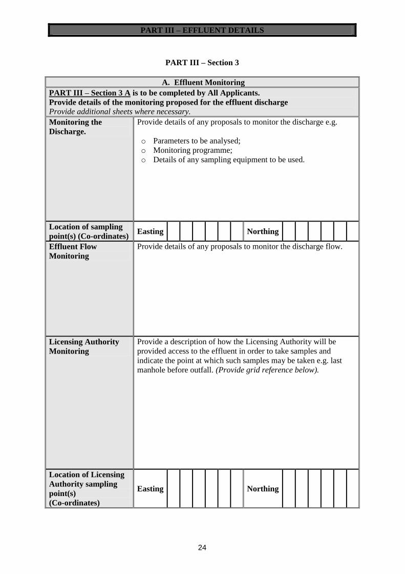
24
PART III – Section 3
A. Effluent Monitoring
PART III – Section 3 A is to be completed by All Applicants.
Provide details of the monitoring proposed for the effluent discharge
Provide additional sheets where necessary.
Monitoring the
Discharge.
Provide details of any proposals to monitor the discharge e.g.
o Parameters to be analysed;
o Monitoring programme;
o Details of any sampling equipment to be used.
Location of sampling
point(s) (Co-ordinates) Easting Northing
Effluent Flow
Monitoring
Provide details of any proposals to monitor the discharge flow.
Licensing Authority
Monitoring
Provide a description of how the Licensing Authority will be
provided access to the effluent in order to take samples and
indicate the point at which such samples may be taken e.g. last
manhole before outfall. (Provide grid reference below).
Location of Licensing
Authority sampling
point(s)
(Co-ordinates)
Easting Northing

PART III – EFFLUENT DETAILS
25
B. Pollution Control
PART III – Section 3 B is to be completed by All Applicants.
Provide details of any pollution control measures proposed.
Provide additional sheets where necessary.
Accidental Discharges Provide details of arrangements to prevent accidental discharges.
Provide below, details of emergency procedures, contact persons and facilities available
to respond to unexpected incidents.
Emergency Response Contact Name
Phone Number (day)
Phone Number (night)
Provide details of any emergency procedure.
Environmental
Management Plan
Is there an Environmental Management Plan in place in respect
of the site?
Yes
No
If ‘Yes’ please submit a copy with this application.

PART IV – DISCHARGE TO GROUNDWATER
26
PART IV – Section 1
A. General Details
Identify why it is not
feasible to discharge to
sewer.
Provide details of the
newspaper notice.
Name of Publication ________________________________
Date of Print ______________________________________
Please include one original plus the required copies of the notice.
PART IV – Section 2
A. Aquifer Characteristics & Receptor Details
Name of Receiving
Water (Waterbody
code)
Location of
Discharge
(Co-ordinates)
Easting Northing
Add additional rows where necessary.
All discharge locations to be indicated clearly on OS Map.
Name of River Basin
District
Provide the name of the River Basin District in which the discharge
is located ________________________.
Water Framework
Directive Waterbody
Status
No Status
Poor Good
Designation* The receiving water is located within the boundary of: (tick as
appropriate)
An SAC, site code _____________.
An SPA, site code _____________.
None of the Above
* Note: Where the discharge is located within the boundary of a
Natura 2000 site (SAC or SPA), or where a discharge is likely to
impact on a nearby SAC / SPA, an Appropriate Assessment (Natura
Impact Statement) must be submitted with this application as
required by Council Directive 92/43/EEC on the Conservation of
Natural Habitats and of Wild Fauna and Flora (Habitats
Directive).

PART IV – DISCHARGE TO GROUNDWATER
27
Is GWDTE Located
within 1km of the
Discharge?
Yes
No
Nearby Surface
Water Features
Show the location of nearby surface waters e.g. rivers, streams,
lakes and field drainage ditches within 250m of the discharge on a
map.
Drinking Water
Abstractions
Provide the name of Public/Group Water Supply Schemes within
1km of the discharge and mark their location on a map.
Mark the location of any domestic wells located within 250m of the
discharge on a map.
Is the discharge located within the Zone of Contribution or Source
Protection Zone of a Groundwater Protection Scheme?
Yes
No
None Delineated
If Yes, provide copy of report and maps.
Soil & Bedrock
Soil type___________________________________________
Subsoil type________________________________________
Bedrock Type_______________________________________
Karst features_______________________________________
Provide copies of reports and maps as relevant.
Aquifer Category
and Vulnerability
Identify Aquifer Category _________________________________
Identify Vulnerability Rating _________________________
Provide copies of reports and maps as relevant.
Topography &
Groundwater Flow
Direction
Identify slope of land at the point of discharge i.e. Steep (>1:5),
Shallow (1:5-1:20), or Relatively Flat (<1:20)_________________
Mark groundwater flow direction on a map.
Depth to Water
Table
Where available provide depth to water table: __________m.
Refer to “Guidance on Applying for a Discharge Licence - Groundwaters” for sources
of information.

PART IV – DISCHARGE TO GROUNDWATER
28
B. Groundwater Background Concentrations
Receiving Water
Background
Concentrations.
Parameter Result (mean)
Total Dissolved Solids mg/l
pH (pH units)
Colour
Temperature ºC
Electrical Conductivity μS/cm
Total Hardness mg/l CaCO3
Total Ammonia as mg/l NH4 – N
Un-ionised Ammonia as mg/l N
Molybdate Reactive Phosphorus as
(unfiltered MRP)
Total Phosphorus as mg/l P
Nitrite as mg/l NO2 – N
Nitrate as mg/l NO3 – N
Total Nitrogen mg/l N
Total organic carbon (TOC)
Chloride mg/l
Sulphate mg/l
Sodium mg/l
Magnesium μg/l
Manganese μg/l
Iron μg/l
Escherichia coli (E.coli) number/100 ml
Total Coliforms number/100 ml
Cryptosproridium number/100 ml
Refer to “Guidance on Applying for a Discharge Licence - Groundwaters” for guidance
on reporting monitoring data and on sampling.

PART IV – DISCHARGE TO GROUNDWATER
29
PART IV – Section 3
A. Impact of Discharge – Site Suitability/Characterisation
Tier 1 Assessment A Tier 1 Assessment must be carried out in support of all
applications to discharge to groundwater.
Tier 2 Assessment
A Tier 2 Assessment must be carried out for the following:
Where the proposed discharge is an input greater than
5 m3/d and less than or equal to 20 m
3/d of domestic waste
water associated with OSWTS and ICWs;
Where the proposed discharge is a trade effluent
(moderate risk);
Where the Tier 1 Assessment indicates uncertainty about
the risk of impact to groundwaters, the Applicant must
proceed to a Tier 2 Assessment.
Note that an Applicant may be requested to conduct a Tier 2
Assessment where the Licensing Authority, following a risk
screening of the discharge, deems that there is a moderate risk of
impact to groundwaters from the discharge.
Tier 3 Assessment
A Tier 3 Assessment must be carried out for applications to
discharge to groundwater that relate to the following activities:
Inputs greater than 20 m3/d of domestic waste water;
Discharges from Landfills;
Where the proposed discharge is a trade effluent (high
risk)
Where the Tier 1 and Tier 2 Assessments indicate
uncertainty about the risk of impact to groundwaters, the
Applicant must proceed to a Tier 3 Assessment.
Note that an Applicant may be requested to conduct a Tier 3
Assessment where the Licensing Authority, following a risk
screening of the discharge, deems that there is a high risk of
impact to groundwaters from the discharge.
Refer to “Guidance on Applying for a Discharge Licence - Groundwaters” for guidance
on Carrying out a Tier 1, Tier 2 and Tier 3 Assessment.
PART IV – DISCHARGE TO GROUNDWATER
30
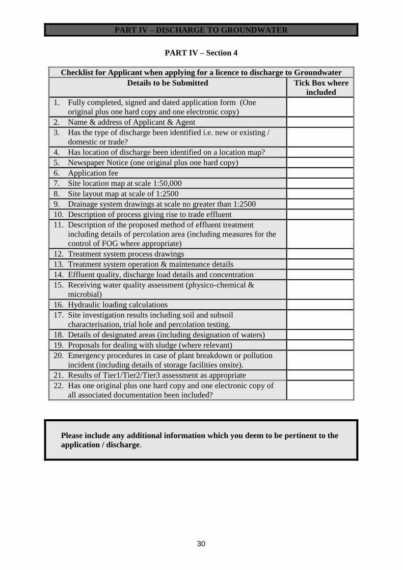
PART IV – Section 4
Checklist for Applicant when applying for a licence to discharge to Groundwater
Details to be Submitted Tick Box where
included
1. Fully completed, signed and dated application form (One
original plus one hard copy and one electronic copy)
2. Name & address of Applicant & Agent
3. Has the type of discharge been identified i.e. new or existing /
domestic or trade?
4. Has location of discharge been identified on a location map?
5. Newspaper Notice (one original plus one hard copy)
6. Application fee
7. Site location map at scale 1:50,000
8. Site layout map at scale of 1:2500
9. Drainage system drawings at scale no greater than 1:2500
10. Description of process giving rise to trade effluent
11. Description of the proposed method of effluent treatment
including details of percolation area (including measures for the
control of FOG where appropriate)
12. Treatment system process drawings
13. Treatment system operation & maintenance details
14. Effluent quality, discharge load details and concentration
15. Receiving water quality assessment (physico-chemical &
microbial)
16. Hydraulic loading calculations
17. Site investigation results including soil and subsoil
characterisation, trial hole and percolation testing.
18. Details of designated areas (including designation of waters)
19. Proposals for dealing with sludge (where relevant)
20. Emergency procedures in case of plant breakdown or pollution
incident (including details of storage facilities onsite).
21. Results of Tier1/Tier2/Tier3 assessment as appropriate
22. Has one original plus one hard copy and one electronic copy of
all associated documentation been included?
Please include any additional information which you deem to be pertinent to the
application / discharge.

APPENDICES
31
Appendix A - Provide details of process related raw materials, products etc. used or generated on site.
Substance EC
Number
Nature of Use Amount
Stored
(tonnes)
Annual Usage
(tonnes)
Danger
Classification
Risk Phrase Safety Phrase
Include copies of Material Safety Data Sheets (MSDS) for materials.
Ref. European Communities (Classification, Packaging, Labelling and Notification of Dangerous Substances) Regulations, 1994
APPENDICES
32
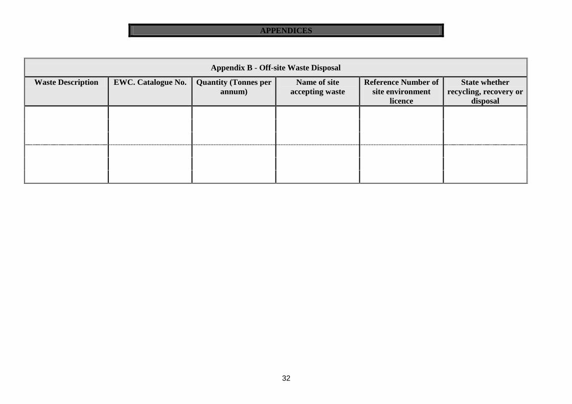
Appendix B - Off-site Waste Disposal
Waste Description EWC. Catalogue No. Quantity (Tonnes per
annum)
Name of site
accepting waste
Reference Number of
site environment
licence
State whether
recycling, recovery or
disposal

APPENDICES
33
Appendix C - Characteristics of Trade and/or Domestic Effluent
The following list of parameters is indicative only. Additional physical, chemical or other characteristics as are pertinent to the effluent in question should
also be identified.
Complete for all applicable sections, giving concentration ranges where available.
Emission Point co-ordinates (One table per emission point):
Parameter
Concentrations in mg/l unless otherwise stated Prior to Treatment (if any) As discharged
Characteristic
Note: Section A = to be completed where discharging
domestic effluent only
Section A-E = to be completed where discharging a trade
effluent.
Max.
Hourly
Max.
Daily Mg/l
Max.
Hourly
Max.
Daily Mg/l % Removal
A Temperature ºC
pH
Biological Oxygen Demand (5 day)
Chemical Oxygen Demand
Suspended Solids
Total Ammonia (as N)
Nitrate (as N)
Total Phosphorus (as P)
Conductivity
Molybdate Reactive Phosphorus (MRP)
Oils, Fats and Greases
Sulphates (as SO4)
Chlorides (as Cl)
Phenols (as C6H5OH)
Detergents (as Lauryl Sulphate)
Escherichia coli (E.coli) number/100
ml
Total Coliforms number/100 ml
Cryptosproridium number/100 ml
B Metals µg/l

APPENDICES
34
Arsenic
Chromium
Copper
Cyanide
Fluoride
Iron
Lead
Magnesium
Manganese
Nickel
Zinc
Other (please specify)
C Pesticides & Solvents:
Atrazine
Dichloromethane µg/l
Simazine µg/l
Toluene µg/l
Xylenes µg/l
D Organohalogen Compounds (Specify)
Organophosphorus Compounds (Specify)
Organotin Compounds (Specify)
Mineral Oils or Hydrocarbons of
petroleum origin
Other toxic substances (Specify)
Colour (degrees hazen)
E Other:
Other relevant characteristics including
fish toxicity data from tests carried out on
all or part of the effluent

APPENDICES
35
Appendix D - Dangerous Substances
Are any of the following chemicals used in the process or stored on
the premises Yes/No
Are residual chemical process materials or chemical
tailings from a process recovered or discharged?
EDC (1, 2 dichloroethane (C2H4C12))
TRI trichloroethylene (C2HC13);
PER perchloroethylene (C2 C14);
TCB trichlorobenzene
Carbon tetrachloride, DDT and pentachlorophenol
Aldrin, dieldrin, isodrin, HCB (hexachlorobenzene), HCBD
(hexachlorobutadiene) and CHCl3 (chloroform)
Cadmium
>100 kg of raw asbestos
Atrazine
Dichloromethane
Simazine
Toluene
Tributyltin
Xylenes
Arsenic
Chromium
Copper
Cyanide
Fluoride
Lead
Nickel
Zinc

Discharges to Groundwater
Guidance to the Applicant
Local Authority Services National Training Group
(WSTG)
August 2011
Revision B

Licensing of discharges to Groundwater by Local Authorities
P:\Cork\DESIGN\projects\252544 - WSNTG Guidance & Training\Training Course - Task 8\Courseware\Guidance
03 November 2009
Local Authority Services National Training Group
August 2011 Monastery Road, Roscrea, Co. Tipperary
Doc. Nr. : 252544/N/R/15/B
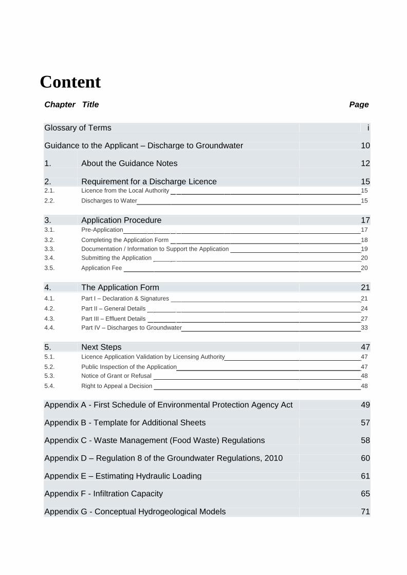
Content
Chapter Title Page
Glossary of Terms i
Guidance to the Applicant – Discharge to Groundwater 10
1. About the Guidance Notes 12
2. Requirement for a Discharge Licence 15 2.1. Licence from the Local Authority 15
2.2. Discharges to Water 15
3. Application Procedure 17 3.1. Pre-Application 17
3.2. Completing the Application Form 18
3.3. Documentation / Information to Support the Application 19
3.4. Submitting the Application 20
3.5. Application Fee 20
4. The Application Form 21
4.1. Part I – Declaration & Signatures 21
4.2. Part II – General Details 24
4.3. Part III – Effluent Details 27
4.4. Part IV – Discharges to Groundwater 33
5. Next Steps 47 5.1. Licence Application Validation by Licensing Authority 47
5.2. Public Inspection of the Application 47
5.3. Notice of Grant or Refusal 48
5.4. Right to Appeal a Decision 48
Appendix A - First Schedule of Environmental Protection Agency Act 49
Appendix B - Template for Additional Sheets 57
Appendix C - Waste Management (Food Waste) Regulations 58
Appendix D – Regulation 8 of the Groundwater Regulations, 2010 60
Appendix E – Estimating Hydraulic Loading 61
Appendix F - Infiltration Capacity 65
Appendix G - Conceptual Hydrogeological Models 71

i
Glossary of Terms The following provides a glossary of terms used in this document. The definitions therein are not to be taken as comprehensive but solely as an aid to the non-technical reader.
Abstraction In relation to water contained in any source of water, means the doing of anything whereby any of
that water is removed from that source of water, whether temporarily or permanently, including
anything whereby the water is so removed for the purpose of being transferred to another source
of water (Source: Water Services Act, 2007)
Agreed Limit of Detection The lowest concentration or quantity of a substance that can be distinguished from the absence of that substance. It should be agreed between the regulator and the applicant.
Appropriate Assessment In accordance with Article 6(3) of the Habitats Directive (92/43/EEC), an Appropriate Assessment
is an evaluation of the potential impacts of a plan or project on the conservation objectives of a
Natura 2000 site (European network of special areas of conservation and special protection
areas), and the development, where necessary, of mitigation or avoidance measures to mitigate
negative effects.
Aquifer A subsurface layer or layers of rock, or other geological strata, of sufficient porosity and
permeability to allow either a significant flow of groundwater or the abstraction of significant
quantities of groundwater (Groundwater Regulations, 2010).
Attenuation A decrease in pollutant concentrations, flux, or toxicity as a function of physical, chemical and/or
biological processes, individually or in combination, in the subsurface environment. Attenuation
processes include dilution, dispersion, filtration, sorption, decay, and retardation.
Authorised person A person appointed in writing by the Minister or by a Water Services Authority / Local Authority for the purposes of enforcing the legislation under which they have been appointed.
Capacity A measure of the ability of groundwater to assimilate or absorb pollutants whilst still maintaining
acceptable water quality in relation to applicable groundwater quality standards. The term relates
primarily to the chemical status of a groundwater body.
Coastal Water The area of surface water on the landward side of a line, every point of which is at a distance of
one nautical mile on the seaward side from the nearest point of the baseline from which the
breadth of territorial waters is measured, extending where appropriate to the outer limit of
transitional waters.

ii
Compliance Point The point (location, depth) at which a compliance value should be met. Generally it is represented by a borehole or monitoring well from which representative groundwater samples can be obtained Compliance Value The concentration of a substance and associated compliance regime that, when not exceeded at the compliance point, will prevent pollution and/or achieve water quality objectives at the receptor.
Conceptual Hydrogeological Model A simplified representation or working description of how a real hydrogeological system is
believed to behave on the basis of qualitative analysis of desk study information, field
observations and field data. A quantitative conceptual model includes preliminary calculations of
water balances, including groundwater flow.
Conservative Pollutants Pollutants which do not readily or easily react or biodegrade in the subsurface environment.
Contaminant (Chemical) Load The volume and concentrations of chemical substances (pollutants) discharged to soil or groundwater.
Diffuse Sources Diffuse sources of pollution are spread over wider geographical areas rather than at individual
point locations. Diffuse sources include general land use activities and landspreading of
industrial, municipal wastes and agricultural organic and inorganic fertilisers.
Direct Input An input to groundwater that bypasses the unsaturated zone (e.g. direct injection through a borehole) or is directly in contact with the groundwater table in an aquifer either year round or seasonally.
Domestic Waste Water Waste water of a composition and concentration (biological and chemical) normally discharged
by a household, and which originates predominantly from the human metabolism or from day to
day domestic type human activities, including washing and sanitation, but does not include fats,
oils, grease or food particles discharged from a premises in the course of, or in preparation for,
providing a related service or carrying on a related trade. (Water Services Act, 2007).
Downgradient The direction of decreasing groundwater levels, i.e. flow direction. Opposite of upgradient.
Dry Weather Flow (Effluent) For a waste water treatment plant, the Dry Weather Flow is the average daily flow to the plant
without any contribution from stormwater inflow or infiltration of groundwater into the waste
water collection system.
Dry Weather Flow (Receiving Water) The Dry Weather Flow of a stream or river is the annual minimum daily mean flow rate with a
return period of 50 years. The Dry Weather Flow is a statistical measure of low flow and usually

iii
requires reliable long term low flow data or sufficient information that would allow the estimation
of the Dry Weather Flow.
Environmental Quality Standard (EQS) The concentration of a particular pollutant or group of pollutants in a receiving water which should not be exceeded in order to protect human health and the environment.
Good Groundwater Chemical Status The chemical status of a body of groundwater which meets all the conditions for good chemical status set out in Groundwater Regulations 2010, regulations 39 to 43. Good Groundwater Status Achieved when both the quantitative and chemical status of a groundwater body are good.
Good Surface Water Chemical Status The chemical status of a body of groundwater which meets all the conditions for good chemical status set out in the Surface Water Regulations 2009, S.I. No. 272 of 2009.
Good Surface Water Status Achieved when both the quantitative and chemical status of a surface water body are good.
Groundwater All water which is below the surface of the ground in the saturation zone and in direct contact with
the ground or subsoil (Groundwater Regulations, 2010). The EPA interpretation of the settings in
which groundwater can occur is presented in Section 3.2.1.
Groundwater Body (GWB) A volume of groundwater defined as a groundwater management unit for the purposes of
reporting to the European Commission under the Water Framework Directive. Groundwater
bodies are defined by aquifers capable of providing more than 10 m3 per day, on average, or
serving more than 50 persons. Groundwater Dependent Terrestrial Ecosystems (GWDTEs) These are groundwater dependent wetlands, whereby the dependency is either on groundwater
flow, level or chemistry as the controlling factors or qualifying interests of associated habitats.
Examples are raised bogs, alkaline fens and turloughs. Groundwater dependent terrestrial
ecosystems are listed on the EPA’s register of protected areas in accordance with Regulation 8
of the Water Policy Regulations, 2003.
Groundwater Protection Scheme (GWPS) A scheme comprising two principal components: a land surface zoning map which encompasses
the hydrogeological elements of risk (of pollution); and a groundwater protection response matrix
for different potentially polluting activities (DELG/EPA/GSI, 1999).
Groundwater Protection Responses (GWPR) Control measures, conditions or precautions recommended as a response to the acceptability of an activity within a groundwater protection zone.
Groundwater Protection Zone (GPZ) A zone delineated by integrating aquifer categories or source protection areas and associated
vulnerability ratings. The zones are shown on a map, each zone being identified by a code, e.g.

iv
SO/H (outer source area with a high vulnerability) or Rk/E (regionally important karstified aquifer
with an extreme vulnerability). Groundwater protection responses are assigned to these zones for
different potentially polluting activities.
Groundwater Recharge Two definitions: a) the process of rainwater or surface water infiltrating to the groundwater table; b) the volume (amount) of water added to a groundwater system.
Groundwater Resource An aquifer capable of providing a groundwater supply of more than 10 m3 a day as an average or serving more than 50 persons.
Hazardous Substances Substances or groups of substances that are toxic, persistent and liable to bio-accumulate, and
other substances or groups of substances which give rise to an equivalent level of concern. A list
of hazardous substances has been published by the EPA (2010a).
Hydraulic Conductivity The rate at which water can move through a unit volume of geological medium under a potential
unit hydraulic gradient. The hydraulic conductivity can be influenced by the properties of the fluid,
including its density, viscosity and temperature, as well as by the properties of the soil or rock.
Hydraulic Gradient The change in total head of water with distance; the slope of the groundwater table or the piezometric surface.
Indirect Input An input to groundwater where the pollutants infiltrate through soil, subsoil and/or bedrock to the groundwater table.
Input The direct or indirect introduction of pollutants into groundwater as a result of human activity.
Integrated Constructed Wetlands (ICWs) Constructed wetlands are artificially constructed or modified wetland systems supporting
vegetation, which provide secondary treatment, by physical and biological means, to effluent from
a primary treatment step. Constructed wetlands may also be used for tertiary treatment (EPA,
2009a). “Integrated constructed wetlands” have been developed in Ireland to integrate water
quality, management of landscape-fit towards improving site aesthetics and enhancement of
biodiversity. ICWs can primarily treat domestic waste water and farmyard soiled water. Guidance
(DEHLG, 2010) is available that outlines the ICW concept, and provides information on site
assessment, design, construction, operation, maintenance and monitoring.
Integrated Pollution Prevention and Control (IPPC) Licence A licence for industrial and other activities issued by the EPA under the Environmental Protection Agency Acts, 1992 to 2011.
Karst A distinctive landform characterised by features such as surface collapses, sinking streams,
swallow holes, caves, turloughs and dry valleys, and a distinctive groundwater flow regime where
drainage is largely underground in solutionally enlarged fissures and conduits.
v
Lake A body of surface water, which may be artificial or natural.
Landfill A waste disposal site or facility used for the deposit of waste onto or under land.
Licence Application An application to a Local Authority or a Water Services Authority for a licence to discharge trade or sewage effluent to waters or to sewer
Licensing Authority Includes the Water Services Authority (as defined in the Water Services Act, 2007) and the
Local Authority (as defined in the Local Government Act, 2001) which includes County Councils
and City Councils.
Limit Objective This objective requires the implementation of all measures necessary to limit inputs of non-
hazardous substances, into groundwater to ensure that such inputs do not cause deterioration in
status or significant and sustained upward trends in their concentrations in groundwater.
Limit Value The mass, expressed in terms of a specific parameter, concentration or level of an emission, or
both a specific concentration and level of an emission, that may not be exceeded during one or
more periods of time. In this guidance, when not exceeded at the source, the limit value will
prevent an unacceptable release to groundwater.
Minimum Reporting Value (MRV) The lowest concentration of a substance that can be determined with a given degree of
confidence using commonly available analytical methods, primarily used in the context of
hazardous substances. MRVs are not necessarily equivalent to limits of detection.
Non-hazardous Substances Pollutants listed in Schedule 2 of the Groundwater Regulations 2010 that are not considered
hazardous, as well as any other non-hazardous pollutants not listed in Schedule 2 but presenting
an existing or potential risk of pollution. Non-hazardous substances are listed in a document by
the EPA (2010a).
On-site Waste Water Treatment Systems (OSWTSs) A generic term for small-scale waste water treatment systems associated with single houses and
small communities or facilities, and mostly associated with septic tanks and intermittent filter
systems offering secondary treatment of raw waste water effluent.
Pathway The route which a particle of water and/or chemical or biological substance takes through the
environment from a source to a receptor location. Pathways are determined by natural
hydrogeological characteristics and the nature of the contaminant, but can also be influenced by
the presence of features resulting from human activities (e.g., abandoned ungrouted boreholes
which can direct surface water and associated pollutants preferentially to groundwater).

vi
Permeability A measure of a soil or rock’s ability or capacity to transmit water under a potential hydraulic gradient (synonymous with hydraulic conductivity).
Point Source Any discernible, confined or discrete conveyance from which pollutants are or may be
discharged. These may exist in the form of pipes, ditches, channels, tunnels, conduits,
containers, and sheds, or may exist as distinct percolation areas, integrated constructed
wetlands, or other surface application of pollutants at individual locations. Examples are
discharges from waste water works and effluent discharges from industry.
Polluting Matter Any substance liable to cause pollution, and, for the purpose of this definition, ‘substance’ includes bacteria and other pathogens, where relevant, and the expression "polluting matter" shall be construed accordingly. (Source European Communities Environmental Objectives (Surface Waters) Regulations, 2009).
Pollution The direct or indirect introduction, as a result of human activity, of substances or heat into the air,
water or land which may be harmful to human health or the quality of aquatic ecosystems or
terrestrial ecosystems directly depending on aquatic ecosystems which result in damage to
material property, or which impair or interfere with amenities and other legitimate uses of the
environment (Groundwater Regulations, 2010). Poorly Productive Aquifers (PPAs) Low-yielding bedrock aquifers that are generally not regarded as important sources of water for
public water supply but that nonetheless may be important in terms of providing domestic and
small community water supplies and of delivering water and associated pollutants to rivers and
lakes via shallow groundwater pathways.
Population Equivalent (p.e.) A conversion value which aims at evaluating non-domestic pollution in reference to domestic pollution fixed by EEC directive (Urban Waste Water Treatment Directive 91/271/EEC) at 60 g/day BOD5.
Pore water Water that occupies void spaces between mineral grains in unlithified (uncemented) sediments.
Preferential Flow A generic term used to describe water movement along favoured pathways through a geological
medium, bypassing other parts of the medium. Examples include pores formed by soil fauna,
plant root channels, weathering cracks, fissures and/or fractures.
Prevent Objective Taking all measures necessary and reasonable to avoid the entry of hazardous substances into groundwater and to avoid any significant increase in their concentration in groundwater.
Priority Substances Those substances or groups of substances, identified by the Commission in accordance with
Article 16(2) of the Water Framework Directive and listed in Tables 11 and 12 of Schedule 6 of

vii
the European Communities Environmental Objectives (Surface Waters) Regulations, 2009 that
have been prioritised for action by the setting of environmental quality standards at Community
level.
Priority Hazardous Substances Those substances or groups of substances forming a subset of priority substances identified by
the Commission in accordance with Article 16(3) of the Water Framework Directive and for which
measures have to be taken to cease or phase-out discharges, losses and emissions and which
are listed in Table 12 of Schedule 6 of the European Communities Environmental Objectives
(Surface Waters) Regulations, 2009.
Receptor-based Water Quality Standards Standards developed to protect receptors, which include drinking water standards, environmental
quality standards for surface waters and minimum reporting values. They are used to develop
compliance values for assessing inputs to groundwater.
Receptors Receptors are existing and potential future groundwater resources, drinking water supplies (e.g.
springs and abstraction wells), surface water bodies into which groundwater discharges (e.g.
streams) and groundwater dependent terrestrial ecosystems (GWDTEs).
Regulator In this document, the EPA or the relevant local authority depending on the type of discharge licence and location.
River A body of inland water flowing for the most part on the surface of the land but which may flow
underground for part of its course (Groundwater Regulations, 2010). Upland rivers are generally
fast flowing and lowland rivers are generally slow flowing and meandering. River Basin The area of land from which all surface water run-off flows, through a sequence of streams, rivers and lakes, into the sea at a single river mouth, estuary or delta.
River Basin District (RBD) A group of river basins formally defined by Water Policy (2003) for the purposes of reporting Water Framework Directive requirements to the European Commission.
River Basin Management Plan (RBMP) A detailed document describing the characteristics of a river basin district, the environmental
objectives that need to be achieved, and the pollution control measures required to achieve
these objectives through a specified work programme.
Saturated Zone The zone below the water table in an aquifer in which all pores and fissures and fractures are filled with water at a pressure that is greater than atmospheric.
Section 4 Licence A licence to discharge to waters, given by local authorities under the Local Government (Water Pollution) Acts 1977 to 1990.

viii
Section 16 Licence A licence to discharge to sewer, given by Irish Water under the Local Government (Water Pollution) Acts 1977 to 1990.
Sewer Drainage pipes and sewers of every description, including storm water sewers, owned by, vested
in or controlled by a water services authority, an authorised provider of water services or a
person providing water services jointly with or on behalf of a water services authority or an
authorised provider of water services, but does not include a drain or service connection (Source:
Water Services Act, 2007)
Sewage Effluent Effluent from any works, apparatus, plant or drainage pipe used for the disposal to waters of sewage, whether treated or untreated (Source: Local Government (Water Pollution) Act 1977)
Significant and Sustained Upward Trend Any statistically and environmentally significant increase in concentration of a pollutant, group of pollutants, or indicator of pollution in groundwater (EPA, 2010b).
Soil (topsoil) The uppermost layer of soil in which plants grow.
Source Pathway Receptor (SPR) Model A SPR model involves identifying whether and how pollution sources are connected to a receptor
via a pathway. A conceptual model provides an understanding of all the relationships between
SPR factors in a particular hydrogeological setting.
Source Protection Area The catchment area around a groundwater source which contributes water to that source (Zone
of Contribution), divided into two areas; the Inner Protection Area (SI) and the Outer Protection
Area (SO). The SI is designed to protect the source against the effects of human activities that
may have an immediate effect on the source, particularly in relation to microbiological pollution. It
is defined by a 100-day time of travel (TOT) from any point below the water table to the source.
The SO covers the remainder of the zone of contribution of the groundwater source.
Special Areas of Conservation (SACs) Areas selected and designated under the Natural Habitats Regulations, 1997 (as amended in 1998 and 2005) for the protection of certain habitats and species.
Storm Water Runoff of rainwater mainly in urban settings during high intensity rainfall events. Stormwater may enter and discharge to groundwater or other receptors through storm drains.
Subsoil Unlithified (uncemented) geological strata or materials beneath the topsoil and above bedrock.
Surface Water A discrete and significant element of surface water such as a lake, reservoir, stream, river or
canal, part of a stream, river or canal, a transitional water or a stretch of coastal water. (European
Communities Environmental Objectives (Surface Waters) Regulations, 2009)

ix
Surface Water Bodies Inland waters, except groundwater, which are on the land surface (such as reservoirs, lakes,
rivers, transitional waters, coastal waters and, under some circumstances, territorial waters) and
which occur within a WFD River Basin District.
Sustainable Urban Drainage Systems (SuDS) Generic term used to describe conveyance systems and control structures designed to intercept,
manage, and dispose of surface drainage and stormwater in urban settings and the built
environment. Components of SuDS may include drains, ponds, soakaways, recharge basins, and
porous pavements.
Threshold Values (TVs) Chemical concentration values for substances listed in Schedule 5 of the Groundwater Regulations (2010), which are used for the purpose of chemical status classification of groundwater bodies.
Trade Effluent Effluent from any works, apparatus, plant or drainage pipe used for the disposal to a waste water
works of any liquid (whether treated or untreated), either with or without particles of matter in
suspension therein, which is discharged from premises used for carrying on any trade or industry
(including mining), but does not include domestic waste water or storm water (Water Services
Act, 2007).
Transitional Waters Bodies of surface water in the vicinity of river mouths which are partly saline in character as a result of their proximity to saline coastal waters, and which are substantially influenced by freshwater flows.
Trigger Level A parameter value specified in a licence or authorisation, the achievement or exceedance of which requires certain actions to be taken by the licensee.
UK TAG The United Kingdom Technical Advisory Group, a partnership of UK environment and
conservation agencies set up to interpret and support the implementation of the Water
Framework Directive. The EPA is an invited member of the UK TAG. Unacceptable Input to Groundwater An input of hazardous substances to groundwater, or pollution resulting from an input of non-
hazardous substances to groundwater, where these inputs are not exempted by the provisions of
Regulation 14 of the Groundwater Regulations (2010).
Unsaturated Zone The zone between the land surface and the water table, in which pores, fractures and fissures are only partially filled with water. Also known as the vadose zone.
Vulnerability The intrinsic geological and hydrogeological characteristics that determine the ease with which groundwater may be contaminated by human activities (Fitzsimmons et al, 2003).

x
Waste Licence A licence for activities in the waste sector given by the EPA under the Waste Management Acts, 1996 to 2010.
Waste Water Effluent Any quantity or volume of waste water generated from a domestic, industrial, or commercial
facility. Typically disposed of via an onsite waste water treatment system or a specially designed
treatment facility such as a waste water treatment plant.
Waste Water Discharge Licence or Certificate of Authorisation Issued by the EPA to sanitary authorities under the Waste water Discharge (Authorisation) Regulations 2007 and 2011.
Water Body A WFD management unit. It refers to all types of waters, including surface water bodies, transitional and coastal water bodies, as well as groundwater bodies.
Water Table The uppermost level of saturation in an aquifer at which the pressure is atmospheric.
Water Pollution The discharge by man, directly or indirectly, of substances or energy into the aquatic
environment, the results of which are such as to cause hazards to human health, harm to living
resources and to aquatic ecosystems, damage to amenities or interference with other legitimate
uses of water.
Water Services Authority Includes a County Council or a City Council as defined in the Local Government Act, 2001, (sanitary authority or local authority).
Zone of Contribution (ZOC) The area surrounding a pumped well or spring that encompasses all areas or features that supply
groundwater to the well or spring. It is defined as the area required to support an abstraction
and/or overflow (in the case of springs) from long-term groundwater recharge.

11
Guidance to the Applicant – Discharge to Groundwater
THESE GUIDANCE NOTES MUST BE READ IN FULL BEFORE THE APPLICATION FORM MAY BE COMPLETED
‘GUIDANCE ON APPLYING FOR
A DISCHARGE LICENCE -
GROUNDWATER’
Application for a Licence to Discharge to Groundwater
The Local Government (Water Pollution) Acts, 1977 & 1990
THESE GUIDANCE NOTES MUST BE READ IN FULL BEFORE THE APPLICATION FORM MAY BE COMPLETED

12
1. About the Guidance Notes
These guidance notes have been prepared to assist persons in the preparation of an application for a licence to discharge effluent to groundwaters. This document should be read with reference to the Groundwater Discharge Application Form available from the licensing authority.
The information contained herein is for guidance only and should not be interpreted as definitive as regards the information a Licensing Authority may seek in respect of a licence application.
These guidance notes have been developed with regard to the Environmental Protection Agency ‘Guidance on the Authorisation of Discharges to Groundwater’, 2011 which was prepared by Henning Moe and Lorraine Gaston, CDM Ireland Ltd. under the guidance of a steering group comprising Donal Daly (EPA) (Chairperson), Colin Byrne (Department of Environment, Heritage and Local Government), Brendan Cooney (Wexford County Council), David Flynn (EPA), Aoife Loughnane (EPA) and Bruce Misstear (Trinity College Dublin) and was reviewed by the following peer review group prior to finalisation: David Ball (Consultant), Jenny Deakin (Trinity College Dublin; formerly Head, Groundwater Section, Department of Primary Industries and Water, Tasmania), Laurence Gill (Trinity College Dublin), Anne Goggin (Limerick County Council), Taly Hunter Williams (Geological Survey of Ireland) and Geoff Wright (formerly Geological Survey of Ireland).
Guidance is provided on the following matters:
Legal obligations to obtain a licence;
General procedures for processing a licence application; Details of a Notice in respect of a licence to discharge to Waters;
Information to be submitted concerning the characteristics of the effluent;
Information required concerning prior treatments;
Information concerning the impact on receiving waters;
Guidance on how to determine the impact of the discharge on the receiving environment;
Section 2 identifies discharges for which a licence to discharge must be held. A licence to discharge to groundwater is required under Sections 4 of the Local Government (Water Pollution) Act, 1977.
This guidance refers to the ‘licensing authority’. In respect of licenses to discharge to groundwaters the licensing authority is the local authority/ sanitary authority / water services authority in whose functional area the discharge is located.
Section 3 provides details of the process involved in making an application to the licensing authority for a licence to discharge effluent to water. The Applicant’s responsibilities in terms of completing the application form and in terms of taking actions as prescribed in legislation are also outlined in this section.

13
Section 4 provides guidance on the completion of the various parts of the application form and on the information to form part of the application. Technical guidance is also provided to assist the applicant in determining the potential impact of the proposed discharge on the environment.
Section 5 refers to the next steps that take place following the making of an application.
Please note that this document does not purport to be and should not be considered a legal interpretation of the provisions and requirements of the Local Government (Water pollution) Acts, 1977 and 1990 and all associated Regulations.
An overview of the procedure involved in licensing of discharges to water is provided hereunder.

14
Process for Licensing Discharges to Water
Applicant determines that a
licence is required
Two Weeks
Valid
Application made available for
public inspection & to Statutory Consultees (water only)
Applicant publishes notice of intention to apply for a discharge licence (discharges to water only)
Applicant submits application to licensing authority
Licensing authority validates application and formally
confirms receipt
Licensing authority assesses application and determines if
‘further information’ is required
Further Further
Information is Information is
not Required Required
Complete
and Resubmit
Application Form
Applicant submits further information
No
Licensee to comply with the conditions of the
licence
Licence Granted
Licensing authority issues decision
Invalid
Yes
or Licensing authority makes decision in absence of further information
Licensing authority obtains further to the cost of the applicant
Yes
No Applicant may appeal decision/conditions to
An Bord Pleanála
Licencsing authority obtains further information to the cost
of the applicant
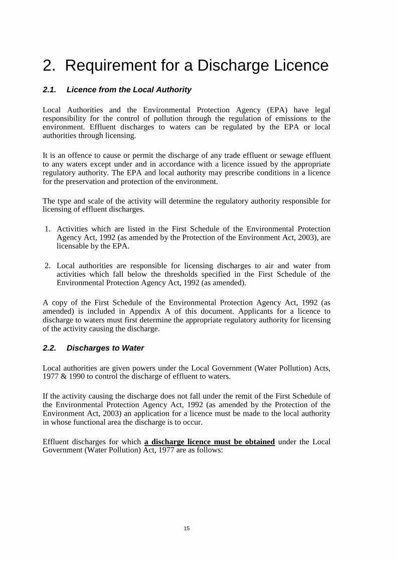
15
Y
2. Requirement for a Discharge Licence
2.1. Licence from the Local Authority
Local Authorities and the Environmental Protection Agency (EPA) have legal responsibility for the control of pollution through the regulation of emissions to the environment. Effluent discharges to waters can be regulated by the EPA or local authorities through licensing.
It is an offence to cause or permit the discharge of any trade effluent or sewage effluent to any waters except under and in accordance with a licence issued by the appropriate regulatory authority. The EPA and local authority may prescribe conditions in a licence for the preservation and protection of the environment.
The type and scale of the activity will determine the regulatory authority responsible for licensing of effluent discharges.
1. Activities which are listed in the First Schedule of the Environmental Protection
Agency Act, 1992 (as amended by the Protection of the Environment Act, 2003), are licensable by the EPA.
2. Local authorities are responsible for licensing discharges to air and water from
activities which fall below the thresholds specified in the First Schedule of the Environmental Protection Agency Act, 1992 (as amended).
A copy of the First Schedule of the Environmental Protection Agency Act, 1992 (as amended) is included in Appendix A of this document. Applicants for a licence to discharge to waters must first determine the appropriate regulatory authority for licensing of the activity causing the discharge.
2.2. Discharges to Water
Local authorities are given powers under the Local Government (Water Pollution) Acts, 1977 & 1990 to control the discharge of effluent to waters.
If the activity causing the discharge does not fall under the remit of the First Schedule of the Environmental Protection Agency Act, 1992 (as amended by the Protection of the Environment Act, 2003) an application for a licence must be made to the local authority in whose functional area the discharge is to occur.
Effluent discharges for which a discharge licence must be obtained under the Local Government (Water Pollution) Act, 1977 are as follows:

16
All domestic wastewater discharges to surface water;
All trade effluent discharges to surface water; All discharges of domestic wastewater greater than 5m
3 in any period of
24 hours which is discharged to an aquifer (groundwater) from a septic tank or other disposal unit by means of a percolation area, soakage pit or other method;
All trade effluent discharges to groundwater;
All trade effluent discharges to sewer.
The following discharges are exempt from having to hold a discharge licence under the Local Government (Water Pollution) Act, 1977:
Discharges to tidal waters from vessels or marine structures;
Discharges from a sewer owned by, vested in or controlled by a Water Services Authority;
Discharges exempted from licensing under Regulations made by the Minister in
accordance with Section 4(10) of the Local Government (Water Pollution) Act, 1977;
Trade effluent discharged by a Water Services Authority in the course of
the performance of its powers and duties, other than from a sewer; Domestic sewage not exceeding in volume 5m
3 in any period of 24 hours which
is discharged to an aquifer from a septic tank or other disposal unit by means of a percolation area, soakage pit or other method (including ICW);
The discharge of domestic-type effluent only to sewer;
The discharge of storm water only to sewer;
Discharges subject to IPPC licensing by the EPA. Such activities are identified in the First Schedule to the Environmental Protection Agency Act, 1992 - 2007

17
3. Application Procedure
3.1 Pre-Application
Initial Consultation with the Licensing Authority
Although not mandatory, it is advisable that applicants make contact with the licensing authority prior to submitting an application for discharges to waters. Prior consultation has the following advantages:
confirmation can be given as to the appropriate licensing authority; information to be submitted with the application can be clarified which may avoid the
possibility of a request for further information and resulting delays in the determination of the licence application;
advice can be sought on any amendments necessary to the existing proposals to allow
an application to be processed ( e.g. the level treatment proposed may not be sufficient); advice on the source of information necessary to complete the application form.
Arrangements for prior consultations should be made by contacting the licensing authority in advance. Contact details are provided on the Application Form.
Notice of Intention to Apply for a Licence to Discharge to Waters
Where a person proposes to submit an application to the licensing authority for a licence to discharge effluent to waters, they must first publish notice of their intention to apply for the licence in a newspaper circulating in the functional area of the licensing authority to which they are applying. This is a legal requirement under the Local Government (Water Pollution) Regulations, 1978.
The requirement to publish such a notice relates to applications for a licence to discharge to waters only i.e. there is no requirement to publish notice of the intention to discharge to sewer.
Applicants should ensure the Notice is placed in a newspaper which is acceptable to the licensing authority. Some licensing authorities have pre-approved lists of acceptable newspapers.
Section 5 of the Local Government (Water Pollution) Regulations, 1978 lists the information that must be contained in the notice as follows:
1. The name of the applicant and the name of the licensing authority to which application is being made;
2. A general description of the effluent; 3. The name and location of the premises from which the effluent is to be discharged; 4. The waters to which the effluent is to be discharged;
5. In the case of the discharge of trade effluent, the nature of the trade or industry from
which the discharge will be generated.

18
The licence application must be submitted to the licensing authority within two weeks of the date of publication of the newspaper notice. A copy of the original newspaper notice must be included with the application form (full page containing the notice showing the date of publication).
Where an application has not been submitted within the two week period following the publication of the notice a further notice may be required. A further notice may also be required where the original notice does not comply with the requirements of the Regulations or is deemed to include inadequate information or is misleading to the public. The costs of all notices are the responsibility of the applicant.
It is important to note that the notice must contain the heading: "Discharge of Effluent to Waters"
The following is the standard template which meets the requirements of the Regulations:
Discharge of Effluent to Waters
Notice is hereby given that Name (insert Applicant’s name) intend to apply to Cavan County Council (insert name of local authority in whose functional
area the discharge is to be located) for a licence to discharge Trade/Sewage/Trade and Sewage (choose relevant option*) effluent from a premises in Location (provide the full address of the premises from which it is intended to discharge) following X Treatment (indicate the level of treatment to be provided to the effluent prior to discharge) to Name (insert the name of the waterbody to which it is intended to discharge the effluent) Groundwater.
* Note: In the case of the discharge of a trade effluent to waters, the newspaper notice is to include a brief description of the nature of the trade / industry from which the effluent is generated.
An application will not be considered by the licensing authority until such time as an appropriate notice has been published in an appropriate newspaper.
3.2 Completing the Application Form
An application for a licence to discharge to water must be made using an application form available from the licensing authority in whose functional area the discharge is proposed.
Multiple discharges from the one premises may require multiple applications. Advice on this matter can be obtained from the licensing authority.
Application forms must be signed and dated by the appropriate person(s) as required in the relevant parts of the form. Failure to provide such signatures will result in the application being deemed incomplete and the licensing authority will be unable to process the application further until such time as the appropriate signatures are provided.

19
Where any part of the application form does not provide sufficient space to supply the information required additional sheets may be attached to the form. A template for additional sheets is provided in Appendix B of this document.
All relevant supporting information must be included with the application form. Such supporting information may include an associated environmental impact statement, a foreshore licence, the results of any investigations carried out, etc. All additional documentation must be complete and include a table of contents. Where the supporting information is related to a particular Part or Section of the application form, this must be referenced on the cover page to the supporting information.
A Checklist is included as part of the application form to ensure that all required information is included with the application.
An application for a licence to discharge to water will be deemed invalid where the applicant fails to provide appropriate signatures, fails to provide appropriate notice of the intention to discharge to waters or fails to provide the appropriate fee in support of the application.
In all other circumstances where a licensing authority identifies that sections of the form have not been completed appropriately, the licensing authority may request further information in accordance with Section 7(3) of the 1978 Regulations.
3.3 Documentation / Information to Support the Application
The Local Government (Water Pollution) Regulations, 1978 require that licence applications must be accompanied by particular information as follows.
1. Plans and other particulars to describe the premises, drainage system and any works, apparatus or plant from which the effluent is to be discharged;
2. Identify the waters to which the discharge is to be made and the point of discharge; 3. Particulars of the nature, chemical composition, anticipated temperature, volume and rate
of discharge; 4. Details of the proposed method of any treatment of the effluent and the period or
periods during which the effluent is to be discharged; 5. A general description of the process or activity giving rise to the discharge;
6. The results of any investigation made into the impact of the discharge on the
receiving waters; 7. Particulars of the quality of the receiving waters. This is to include as a minimum, a
description of the background chemical and bacteriological condition of the receiving water.
8. Details of any potential effects of the discharge on the receiving waters.
The application form includes sections for the insertion of the aforementioned information.
The licensing authority may, in accordance with the Local Government (Water Pollution) Regulations, 1978 request further information as may be reasonably requested to assist them in making a determination on the application such as particulars of the quality and volume of the

20
discharge, the effects of the discharge on the receiving waters and the results of any investigation made.
The Regulations require that additional information requested by the licensing authority should be provided within 3 months of the request. If an applicant fails to submit the requested information within this timeframe the licensing authority may carry out investigations necessary to gather the information requested, the cost of which may be charged to the applicant. Alternatively, the licensing authority may proceed to make a determination of the application in the absence of such information. 3.4 Submitting the Application
Applicants for a licence to discharge effluent to waters, are required to submit one original signed hard copy of the application form and any additional sheets plus three copies and any additional sheets to the licensing authority. An original copy of the newspaper notice and three copies are to be included with the application form. The completed application form, accompanied by all relevant information and payment, is to be sent to the address given on the application form.
3.5 Application Fee
Applications must be accompanied by an application fee. The amount of the fee is prescribed in the Local Government (Water Pollution) (Fees) Regulations, 2001 and currently stands at €380. This fee may be revised at any time by the Minister through the introduction of amendment legislation.
The application will not be processed unless the correct fee has been included.
Payment is to be made by cheque or bank draft made payable to the appropriate licensing authority.

21
4. The Application Form
Part I – Declaration & Signatures This part of the application form is to be completed by all applicants for a licence to discharge to any waterbody. Declarations and signatures are required from the Applicant confirming that they are aware of their legal obligations under the Local Government (Water Pollution) Acts to implement the conditions of any licence granted in terms of the discharge identified in their application.
Part II – General Details This part is to be completed by all applicants for a licence to discharge to any waterbody. This part of the form requires that contact details of the Applicant (and as applicable the Agent making the application on behalf of the Applicant) are provided. Details about the premises and activity from which the effluent discharge relates are also to be provided in this part of the application form.
Part III – Effluent Details This part is to be completed by all applicants for a licence to discharge to any waterbody. Details on the effluent quality and volume must be provided in this part of the application form. Any proposed effluent treatment and pollution control measures are also to be detailed in this part.
Part IV – Discharges to Groundwater This part is to be completed by all applicants where it is proposed to discharge trade effluent or domestic wastewater (or both) to any groundwater. Information on the existing receiving water quality must be provided. Guidance is provided on determining the potential impact of the discharge on the receiving waters.
The applicant is advised to read the entire application form plus these guidance notes before commencing to complete the form. The applicant should first complete Part II through to Part IV before providing the signatures of the applicant and responsible person in Part I.
4.1. Part I – Declaration & Signatures
PART I - Section 1
This section of the application form requires that the signatures of the Applicant and, where applicable, the Agent making the application on behalf of the Applicant.
The Applicant and, where appropriate the Agent must attach duly authorised signatures confirming their respective responsibilities for the preparation of the licence and in respect of the Applicant that they are aware of the legal obligations attaching to compliance with licence conditions.

22
Definitions
Applicant The ‘Applicant’ can be an individual, group of
individuals or corporate body whose activities are responsible for the discharge. The Applicant is legally
responsible for ensuring compliance with the licence
conditions where it is granted.
Agent The ‘Agent’ is nominated by the Applicant to act on their behalf for the purposes of completing the application form. The Agent has no responsibility relating to the
implementation of the licence where it is granted.
Where signatures of the Applicant are sought, they must be provided as follows:
Where the Applicant is an individual – the signature of the individual is required; Where the Applicant is a group of individuals – the signature of one individual in the
group is required; Where the Applicant is a Company – the signature of a duly authorised person
within that Company is required e.g. Director of the Company.
Where a licence is granted, the legal responsibility for ensuring compliance with the licence will rest with the legal entity itself i.e. the individual, Group or Company as the case may be.
Class of Discharge Applicants are required to provide information as to the class of discharge to which the application relates, whether the discharge is a trade effluent, domestic effluent or a combination of both. (Refer to the Glossary of this guidance for definitions of each).
Compliance with Terms of Licence The Applicant is required to declare that they are fully aware of the legal obligations under the Local Government (Water Pollution) Act, 1977 to abide by the conditions of the licence (where it is granted) and acknowledge that they may be subject to criminal liability whereby the terms of the licence are not complied with.
PART I - Section 2
Section 2 of the application form outlines the legal obligations imposed on the local authority (licensing authority) to make licence applications available for inspection by third parties.
Disclosure of Information Under the Freedom of Information Act, 1997 (as amended) the local authority must make any records held by them available to the public. This includes licences granted under the Local Government (Water Pollution) 1977 and associated documentation which may include the completed application form.
There are further legislative obligations on the licensing authority under the Local Government (Water Pollution) Regulations, 1978, to make licence applications available for public inspection where it relates to a discharge to waters. The public may provide submissions or comments in relation to a licence application which the licensing authority must have regard to when making a determination as to whether or not to grant a licence.

23
If an application is for a discharge to waters, the licensing authority is also required to make a copy of it available to the Department of the Marine and the Central Fisheries Board and the Inland Fisheries Ireland. These Bodies have a period of four weeks from the date of receipt of a copy of an application to make submissions or comments in relation to a licence application which the licensing authority must have regard to when making a determination as to whether or not to grant a licence.
The Applicant, and where applicable, the Agent are asked to sign a declaration to confirm that they have made themselves aware of the provisions of the Freedom of Information Act and that they understand that there is a legal obligation on the licensing authority to make the discharge licence application available for inspection by third parties.
Confidentiality When completing an application form, any information which is considered as confidential must be clearly identified. The grounds for which the information is considered confidential must also be clearly stated.
Circumstances under which confidentiality may apply include where the information is commercially sensitive or includes matters of National security for example: trade secrets of a person; financial, commercial, scientific or technical or other information whose disclosure could
reasonably be expected to result in a material financial loss or gain to the person to whom the information relates, or could prejudice the competitive position of that person in the conduct of his or her profession or business or otherwise in his or her occupation;
data whose disclosure could prejudice the conduct or outcome of contractual or other
negotiations of the person to whom the information relates; data on State security or international relations;
Where information is deemed confidential, the licensing authority will remove the information from the application form and/or licence before making the documentation available for inspection by third parties. For this reason it is requested that where feasible, information that is considered to be confidential should be submitted in a manner that will allow it to be easily removed e.g. on an additional sheet. All such information should be clearly marked as ‘Confidential’. The licensing authority will mark in the public file where confidential information has been removed.
The Applicant and as appropriate the Agent acting on behalf of the Applicant are required to sign a declaration acknowledging the obligations of the Licensing Authority in respect of the disclosure of information and confidentiality.
False or Misleading Information Article 6 of the Local Government (Water Pollution) Act, 1977 states that it is an offence to
knowingly or deliberately provide false or misleading information in a licence application. The
Applicant is liable, on summary conviction, to a fine. Any licence granted on the basis of such
false information shall be revoked.

24
The Applicant (and where applicable the Agent acting required to sign a declaration that the information is knowledge of the Applicant and the Agent.
on behalf of the Applicant) is accurate and true to the best
4.2. Part II – General Details
PART II - Section 1
Part II, Section 1 of the application form requires contact details for the Applicant (whose activities are causing the discharge and where applicable the Agent (the person or persons who have prepared the application on behalf of the Applicant).
Both the applicant and (where applicable) the agent will be communicated with during the processing and determination of the licence application. When a licence is granted, further communications will be to the Applicant (who then becomes the licensee).
A. Details of the Applicant
Details must be provided of the Applicant including a named person to whom all correspondence subsequent to the issuance of the licence should be addressed. (Principal Contact).
If a licence is granted it will be granted in the name of the Applicant (which may be an individual, group of individuals or a Company).
Note: Were the Applicant is a group, such as a management group or residents association, and such group ceases to exist or the Principal Contact changes, details should be submitted to the Licensing Authority immediately. Where the Applicant is a Company, any changes in the structure of Company that would result in a change in the principal contact or any sale of the Company must be notified to the Licensing Authority immediately.
Where the Applicant is a Company a Certificate of Incorporation must be included with the application listing the names of Directors.
B. Details of the Agent Where an Agent is making the application on behalf of the Applicant, details must be provided of the Agent including a named person to whom all correspondence concerning the licence application should be addressed (Principal Contact).
PART II - Section 2 Section 2 of Part II requires details about the premises from which the effluent is generated.
A (i) Site Details
Details must be provided concerning the address of the premises from which it is proposed to discharge effluent. A grid reference (Irish Transverse Mercator) for the site must also be

25
provided. This shall comprise six–digit Easting and Northing coordinates. The grid reference should represent the centre point of the site. Where do I get co-ordinates from?
The OSI have developed an interactive mapping system which gives the Irish Transverse Mercator (ITM) co-ordinates i.e. the grid reference http://ims0.osiemaps.ie/website/publicviewer/main.aspx Provide six digit easting and northing co-ordinates.
Existing Permissions/Licenses Information is to be provided of any existing planning permission and/or discharge licenses that are in place for the premises to which the licence application relates. Reference numbers must be provided.
Site Maps/Drawings Applications must be accompanied by a site location map, site layout map and site drainage drawings. The following requirements apply:-
All maps and drawings must be to scale and must indicate the scale on the map/drawing. The scale must be appropriate to the information presented in the map/drawing.
All maps and drawings are to be printed on paper which is not below A3 size or above
A0 size. All maps and drawings must be uniquely numbered and labelled. The map/drawing
label must identify what is shown on the map/drawing. All maps and drawings must refer to the Part of the application form to which they relate
e.g. in this case, the site location map relates to Part II – Section 2. All maps and drawings must have a north arrow. All maps must indicate the relevant Ordnance Survey Ireland licence number and
sheet number. All maps/drawings must show the date of production.
The specific details to be provided in each map are outlined below:
1. Site Location Map
Show clearly, on a Discovery Series Map, the location of the premises from which it is
proposed to discharge. Clearly identify the Townland(s) in which the site is located.
Show clearly the boundaries of the site from which the discharge is generated.
Identify clearly the point of discharge.
Identify any surface water or groundwater abstractions in the area.
Provide the map at a scale of not less than 1:10000.
2. Site Layout Map Show clearly the boundaries of the site from which the discharge is generated.

26
Where the discharge relates to an existing development, provide a footprint of all existing over-ground and underground buildings / structures located within the boundary of the site.
Where the discharge relates to a proposed development, provide a footprint of all proposed over-ground and underground buildings / structures located within the boundary of the site. Identify also any existing structures located within the site boundary.
Where effluent treatment is provided prior to discharge, clearly identify the footprint
of the treatment system and all associated facilities e.g. storage tanks, soakaway areas/percolation areas etc.
Clearly identify the discharge point location(s) on the map i.e. the point(s) at which the
discharge enters the percolation area, soakage pit or other method. Clearly identify the location(s) of any effluent sampling chambers.
Clearly identify the groundwater sampling locations used for the purpose of the
application. Clearly identify areas on the site where raw materials, products and wastes are stored.
Provide the map at a scale of not less than 1:2500.
3. Site Drainage System Drawings
Show clearly the boundaries of the site from which the discharge is generated.
Clearly identify and annotate the existing and proposed foul water and storm water drainage on the site. Indicate the location of any emergency overflows.
Show the location of any existing and proposed treatment facility on site and the
location of all effluent discharge points and associated percolation areas (or other). Provide the map at a scale of not less than 1:500.
Other maps to be submitted with the application form include aquifer vulnerability maps and soil and bedrock maps. Details of where to source these maps is provided hereunder in Part IV – Section 2.
A (ii) Type of Premises
Information must be provided to identify the sector from which the discharge will be generated e.g. from an industrial activity, commercial activity etc. This information will provide the licensing authority with a general indication of the effluent characteristics likely to be encountered at the premises e.g. effluent generated from a facility involved in food preparation is likely to have a greater fats, oils and greases content than a domestic discharge.
A (iii) Activities Carried Out on Site
Details are to be provided of the activities carried out on site in order to provide the licensing authority with information on the potentially polluting material stored, produced and discharged from the site.
Operational Information: Where the effluent is generated from a commercial or industrial activity a brief overview of the primary processes / activities carried out on site is to be provided. This overview should include

27
a schematic process flow diagram of each unit operation and a brief description detailing its purpose. Identify all elements of the process where aqueous emissions to the environment are generated. Identify any sources of contaminated wash water or contaminated drainage from the site. Process Materials, Products & Waste Disposal: Where effluent is generated from a commercial or industrial activity Appendix A and Appendix B of the application form are to be completed.
Appendix A requires that a list of raw materials used/stored on site be provided. This is also to include any cleaning products, any fuels and any thermal control products used/stored on site. Where known, the material’s EC number and classification under the European Communities (Classification, Packaging, Labelling and Notification of Dangerous Substances) Regulations, 1994 should be included. Material Safety Data Sheets should also to be provided.
Appendix B requires details of all wastes generated on site. Applicants are required to identify how these wastes are removed from site. Refer to the European Waste Catalogue and Hazardous Waste List published by the EPA for more information on the European Waste Catalogue Number.
4.3. Part III – Effluent Details
PART III - Section 1 Section 1 of Part III of the application form requires details of the effluent to be discharged.
Were an application refers to a new discharge information must be provided to show how the volume and characteristics of the discharge were determined. If the application refers to an existing discharge the volume and characteristics should be derived from monitoring data.
A. Effluent Details Type of effluent The type of effluent must be defined as domestic, trade or a combination of both. Definitions of domestic and trade effluents are provided in the Glossary of Terms provided at the start of this guidance document.
Population Equivalent The pollution loading should be characterised by measurements or estimates for the various physical and chemical parameters of the effluent.
The pollution loading from domestic effluents should be expressed in terms of the pollution loading generated by an equivalent domestic population, referred to as the population equivalent (p.e.). One population equivalent has a five day biochemical oxygen demand (BOD5) of 60 grams of oxygen per day. Therefore, if the BOD component of the pollution loading is known (kg/day) the p.e. can be calculated by dividing by 60 and multiplying by 1000. Similarly, if the population responsible for a domestic effluent discharge is 500, the p.e is 500 and the pollution loading is 30kg/BOD/day (500x60/1000).

28
For a proposed new discharge, the BOD load in the effluent may be estimated using population data. For an existing discharge, the BOD load in the effluent should be measured based on flow proportional composite sampling.
Dry Weather Flow Applicants must provide information on the rate and volume of the discharge. For domestic effluents flow is expressed in terms of dry weather flow (DWF). DWF is expressed as litres/person/day and can range typically from 110 litres to 180 litres/ person/day (typically taken as 150 l/h/d). Allowance needs to be made for infiltration.
For an existing discharge measured flow monitoring data should be provided.
Applications must include information on the method used to determine the p.e. and the methodology used in establishing DWF.
Note: Flow rates and organic pollution load of domestic effluent from commercial and institutional premises will vary from that of residential premises depending on the activities carried out on the premises. Information on typical flows and loads from different types of commercial premises may be sourced from the EPA Wastewater Treatment Manuals.
Trade Effluent – Flow Data: Trade effluent flows are often influenced by the process / activity from which the effluent is generated. Information on daily variations and seasonal variations must be provided.
Where the effluent discharges from the premises consists of a combination of trade and domestic effluent, the contribution from both categories of effluent must be addressed separately in the sections provided in the application form.
Effluent Characteristics Information must be provided on the characteristics of waste waters / effluents before treatment (where it is provided) and as discharged. The information is to be provided in Appendix C and Appendix D of the application Form.
Appendix C: Details of the physical, chemical and bacteriological components of the effluent are to be identified in Appendix C.
For domestic type effluent, only Section A of Appendix C needs to be completed. Information on the typical characteristics of domestic effluent is provided in EPA Wastewater Treatment Manuals.
For trade effluents all sections must be completed. The characteristics of effluents will be largely determined by the raw materials and the processes that result in effluent discharges. Where treatment is provided prior to discharge the characteristics prior to treatment and as discharged must be provided. Where a parameter is not applicable to the effluent this must be indicated by insertion of N/A in the columns in Appendix C under ‘As discharged’. Failure to indicate thus may result in a request for additional information.
29
It is the responsibility of the Applicant to provide complete information on the full characteristic of the effluent which are known to the Applicant and could be inferred for the raw materials and processes which result in the discharge
For an existing discharge the characteristics of the effluent shall be determined from monitoring and sampling based on 24-hour composite flow proportional samples. Appendix D: Details of dangerous substances stored on the site or used in any industrial / commercial activity shall be provided in Appendix D. In addition, information should be provided concerning the recovery and disposal of dangerous substances, for example:- empty drums which contained dangerous substances are returned to the suppliers
for disposal; washings of vessels or containers containing dangerous substances;
stillings, sludges or residuals from processes.
Effluent Variability: Variations in the volume or characteristics of the effluent should be described. Such variability may be related to inter alia: seasonal activities such as effluents from holiday homes and caravan parks, manufacture
of milk products such as cheese making, discharge of ullage form brewing operations, etc.; batch manufacturing processes resulting in varying effluent types on different
days/weeks/ months; changes in activities carried out within the boundary of the site to which the
discharge relates;
Fats, Oils & Greases: Food preparation activities tend to produce effluents with higher fats, oils and greases (FOG) content than would be expected in a domestic-type effluent discharge only. The typical concentration of FOG in domestic waste water is in the range of 50mg/l to 100mg/l. High FOG concentrations can cause problems in the receiving waters. If the effluent results either wholly or partially through food preparation activities or other such activities which produces an effluent with elevated FOG e.g. dairy process, information must be provided on proposals for recovery, treatment, removal and disposal of FOG prior to discharge.
Food Waste Management: The Waste Management (Food Waste) Regulations, 2009 require that major generators of food waste make provisions for source segregation of food waste and to keep such material separate from non-biodegradable materials, other waste and contaminants for separate disposal. Schedule 1 of the regulations identify the classes of premises to which the Regulations apply (a copy of the Schedule is provided in Appendix C).
The regulations prescribe that where source segregation is to be provided, the producer must not use purpose built mechanical devices to shred or hydrate or otherwise alter the structure of food waste for the purposes of facilitating its discharge in waste water to a service connection, drain or sewer.
A licensing authority may require an applicant to provide evidence of food waste segregation in accordance with the provisions of the Regulations.
30
Other Discharges: Information should be provided of any other discharges from the site which are already subject to a licence or don’t require a licence and which are not the subject of the licence application. Such discharges include storm water. The locations and particulars of other discharges should be provided. Where there are none, this should be stated on the application form.
Water Supply: The source of all water supplies to the site e.g. from a well, public mains, private scheme etc. must be provided including estimations or measurements of the volume of water used per day. PART III - Section 2
Section 2 of Part III refers to on-site treatment facilities. Where effluents are treated prior to discharge details are to be provided concerning the type of treatment and operational arrangements. Where the treatment system is operated and maintained by a third party contact details must be provided.
Waste Water Treatment System Overview
The particulars of the treatment system proposed must be provided. Details to be submitted should include but are not limited to the following:
Level of treatment e.g. primary, secondary, tertiary etc. Type of treatment e.g. septic tank, lamella type primary settlement, activated sludge
secondary treatment, tertiary polishing filter, sludge thickening and dewatering, etc. Details of the treatment system such as the treatment system design, capacity, size of
the various unit processes, facilities for expansion, etc. Schematic process flow diagram. Where the works are a package plant, the type and model are to be detailed and
the manufacturer’s technical information is to be submitted. Details of the percolation area; Site drawing at an appropriate scale identifying points at which the licensing authority
can have access for sampling purposes. Performance guarantees for the various treatment processes e.g. level of reduction of
a parameter (% removal), treated effluent concentrations, limits (ph 6.5 -8.5), etc. Depth below ground of the base of the discharge pipe(s).
Direct / Indirect Discharge
Specify whether the discharge to groundwater will be by direct or indirect discharge.
A direct discharge is one that is discharged to the aquifer without percolation through the ground or subsoil i.e. the unsaturated zone (e.g. through a borehole) or is directly in contact with the groundwater table in an aquifer either year round or seasonally. Note that direct discharges to groundwater are prohibited under Section 8 of the European Communities Environmental Objectives (Groundwater) Regulations 2010. There is however circumstances whereby direct discharges may be permitted subject prior authorisation, as prescribed in the Regulations and reproduced in Appendix D of this guidance for your information.

31
An indirect discharge is one where the pollutants infiltrate through soil, subsoil and/or bedrock to the groundwater table. An indirect discharge may be through a percolation area, soakage pit, filter system, constructed wetland or other method. The Applicant is required to provide design details and construction methodology for the relevant infiltration system. Hydraulic Loading The hydraulic loading is the quantity of water and/or effluent that percolates to groundwater, and is typically expressed as a volumetric flow rate over a given percolation area. Unless capped, natural recharge can be a significant component of the total loading over the input area. Information about the expected hydraulic loading should be provided by the applicant. Hydraulic loading to groundwater has two components:
The effluent;
Natural recharge from rainfall.
Hydraulic loading to groundwater can be estimated using the following equation:
Total hydraulic loading = Effluent discharge rate + Natural recharge rate
The Applicant is required to provide an estimate of the hydraulic loading rate to the infiltration system. Refer to Appendix E of this guidance for the method of calculation the hydraulic loading rate.
Maintenance: Where the effluent is to undergo treatment prior to discharge, details must be provided concerning the arrangements that have been put in place for maintaining the treatment system. Such details should include:
Arrangements for undertaking maintenance required in the manufacturer’s technical
documents; Details of the person/company responsible for the maintenance of the treatment system;
Details of any proposed maintenance programme; Details of any spare parts to be held on site;
Frequency of de-sludging;
The Applicant should be aware that any authorisation to discharge to groundwaters shall be subject to best practice with regard to proper operation and maintenance of any OSWTS, as directed by the DEHLG circular (Reference PSSP 1/10) on performance of OSWTS.
Plant Failure: Information is to be provided concerning measures in place to detect any failure of the treatment system. Such measures may include: Arrangements for inspections and monitoring. The provision of an alarm call-out system or telemetry system;
Sludge: Where sludge is a by-product of the effluent treatment, information must be provided concerning sludge disposal. Such information may comprise:
A copy of a sludge management plan where one has been developed; Details of the volumes of sludge that will be generated;

32
Details of any sludge treatment proposed before removal from site e.g. dewatering; Details of volumes of sludge and where the sludge is to be sent e.g. to agricultural lands or
to a waste recovery / disposal facility; Details the person / company authorised to collect such waste from the premises
(waste collection permit holder);
PART III - Section 3
Section 3 of Part III seeks information on proposals for monitoring the discharge and proposals for controlling accidental discharges and details of emergency procedures.
A. Effluent Monitoring
Information should be provided concerning any proposals to carry out monitoring of effluent volumes and characteristics. Any proposals for providing access to the effluent for the purposes on monitoring must also be provided.
Such information may include the following:
Type of flow equipment to be used; Location of flow monitoring equipment;
Number of sampling events to be undertaken per year and frequency of same;
Parameters to be analysed; Location of sampling point e.g. sample to be taken from manhole located 1m upstream
of the discharge point; Details of sampling equipment to be used e.g. permanent / temporary, time or
flow proportional, composite or grab, make and model of equipment (if any); Accreditation details (if any) of the laboratory undertaking the effluent analysis;
The licensing authority may require access to the site for the purposes of compliance monitoring. Information should be provided concerning arrangements in place to allow for monitoring by the licensing authority. Precise details should be provided including a description of the monitoring point with coordinates defining the location.
B. Pollution Control
Information is required on any arrangements that are in place to prevent accidental discharges and any arrangements to be put in place for emergency responses. Some examples of measures to prevent the accidental discharge of effluent are provided below:
The control of the movement of material on site;
Bunding of areas used for the storage of potentially polluting matter; Alarm system in the event of plant failure;
Provision of storage tanks to hold the effluent where the effluent treatment plant fails;
Contact details are to be provided of the person to be contacted by the licensing authority in the event of an accidental discharge or other event for which the licensing authority may require urgent actions to be taken by the licensee.

33
4.4. Part IV – Discharges to Groundwater Part IV requires information on the body of water into which it is proposed to discharge effluent.
PART IV - Section 1
The application form asks for an explanation as to why it is not feasible to discharge to sewer. Reasons for such should be provided which may include: None available;
Access to same not immediately available;
No capacity in sewer;
No capacity in downstream waste water treatment plant.
Public Notice There is a legal requirement, under the Local Government (Water Pollution) Regulations, 1978, on applicants for a discharge to waters, to publish a Notice of their intention to apply for the licence in a newspaper circulating in the functional area of the local authority in which it is proposed to discharge to waters.
Section 1 of Part IV of the application form concerns information on the Notice published in accordance with the Regulations. Applicants are required to provide details of the publication together with the full page of the newspaper containing the Notice. The newspaper should be one that is circulated in the area of the discharge and has an adequate readership to make the community aware of the proposal. Applicants should contact the licensing authority to ensure that the newspaper intended to contain the Notice is acceptable to the licensing authority. The notice should clearly identify the applicant and the location of the discharge. Where applicable, any local descriptions for the receiving waters should be provided in addition to the recorded name where this would assist in identification.
PART IV - Section 2
Section 2 concerns details of the waters which are to receive the discharge.
A. Aquifer Characteristics & Receptor Details
Name of Receiving Waters (Waterbody Code) Information is required to accurately identify the receiving water body and the location within which the discharge is proposed. Information on the groundwater name and waterbody code can be obtained from the national website www.wfdireland.ie (an example of a groundwater name and code is Abbeyfeale - IE_SH_G_001). The coordinates of the discharge are also to be provided. Where an application refers to multiple discharges (which must firstly be discussed with the licensing authority) each discharge point must be given an individual identification code e.g. point 1, point 2 etc. and an associated grid reference.

34
Status The implementation of the Water Framework Directive (2000/60/EC) has defined the status of all water bodies on a River Basin District basis. Applicants are required to state the River Basin District containing the receiving water body and its status. Information on the boundaries of River Basin Districts and on the status of water bodies can be obtained from the national website www.wfdireland.ie.
River Basin Management Plans have been put in place to achieve Good Status in all water bodies. These River Basin Management Plans contain measures to achieve this objective. Applicants are encouraged to refer to the appropriate River Basin Management Plan prior to submitting an application.
Designation Applicants are required to provide information on the designation and status of the receiving water body. The waterbody to receive the discharge may be designated for a particular use or may be designated as needing protection due to its sensitivity to pollution or because it contains species or habitats of particular importance. Discharges to designated waters may be required to meet more stringent discharge standards.
Designations may include: Special Area of Conservation (SAC) (European Communities (Natural Habitats)
Regulations, 1997) Special Protected Area (SPA) (European Communities (Natural Habitats) Regulations,
1997)
Details of designated areas are held by the EPA (www.epa.ie). Also, the National Parks and Wildlife Services (www.npws.ie) hold datasets on SACs and SPAs.
Where a discharge is located within the boundary of an SAC or SPA (Natura 2000 site) or where a discharge is likely to impact on a nearby SAC / SPA, an Appropriate Assessment (Natura Impact Statement) must be submitted with the discharge licence
application. This requirement is to comply with Council Directive 92/43/EEC on the Conservation of Natural Habitats and of Wild Fauna and Flora (Habitats Directive) [and the European Communities (Natural Habitats) Regulations, 1997]. An Appropriate Assessment is an assessment of the implications of the discharge on the designated site in relation to the conservation objectives of the site. An Appropriate Assessment must be undertaken by a suitably qualified person, i.e. an ecologist.
Groundwater Dependant Terrestrial Ecosystems (GWDTEs) Groundwater dependent terrestrial ecosystems (GWDTEs) are wetlands where the ecology depends on a certain level or range of groundwater flows, water levels, or chemical parameters being maintained. GWDTEs include turloughs, Cladium fen, alkaline fen, petrifying spring habitats. For further information on GWDTEs refer to the Western River Basin District publication, Water Framework Directive Annex IV Protected Areas: Water Dependant Habitats and Species and High Status Sites (December 2008) available to download through the WFDIreland website at: http://www.wfdireland.ie/docs/27_HighStatusSites/.

35
Turlough data is contained in the ‘Karst Features’ database available for download through the Geological Survey of Ireland (GSI) website (www.gsi.ie). Data on Cladium fen, alkaline fen, petrifying spring habitats is available directly from the National Parks and Wildlife Services (NPWS).
Nearby Surface Water Features The Applicant is asked to identify on a Discovery Series Map, the location of streams, rivers, lakes, and field drainage ditches within 250m of the discharge location. A high frequency of surface waters is an indication of a high or perched water table.
Drinking Water Abstractions The Applicant is asked to provide the name of any Public/Group Water Supply Schemes located within 1km of the discharge location and is to show their location clearly on a Discovery Series Map. The Applicant is also asked show the location of any domestic wells within 250m of the discharge on a Discovery Series Map both upgradient and downgradient groundwater abstractions are to be identified.
Groundwater Protection Schemes are county-based projects that are undertaken jointly between the GSI and the respective Local Authority. The overall aim of the groundwater protection scheme is to preserve the quality of groundwater, particularly for drinking water purposes. The location of Groundwater Protection Schemes are provided through the Geological Survey of Ireland website through their Groundwater WebMapping service at: http://www.gsi.ie/Mapping.htm.
The Groundwater Protection Scheme map shows the zone of contribution and source protection zones. The zone of contribution is the area surrounding a pumped well that encompasses all areas or features that supply groundwater recharge to the well. It is defined as the area required to support an abstraction from long-term groundwater recharge. The source protection zone is the catchment area around a groundwater source which contributes water to that source (Zone of Contribution) and is divided into two areas:
Inner Protection Area (SI), designed to give protection from microbial pollution; Outer Protection Area (SO), encompassing the remainder of the zone of
contribution (ZOC) of the well.
Soil & Bedrock Soil and subsoil data may be sourced from Teagasc and the EPA (http://gis.epa.ie/DataDownload.aspx). Much of Ireland’s soil data has been derived from the National Soil Survey of Ireland which was carried out in the ‘70s and ‘80s. Teagasc is currently carrying out further soil mapping work through the Irish Soil Information System (ISIS) and should be contacted for up to date data. Contact details are available through their website: http://www.teagasc.ie/.
Bedrock geology data (1:100,000 scale map) and data on the location of karst features is available for download through the Geological Survey of Ireland (GSI) website (www.gsi.ie). Teagasc subsoil data is also available for download from the GSI website.

36
Aquifer Category and Vulnerability The Applicant is asked to identify the aquifer category and vulnerability rating of the aquifer to which it is proposed to discharge.
All aquifers across Ireland have been classified into one of eight aquifer categories1 under
the headings of regionally important, locally important or poor as follows: Regionally Important (R) Aquifers Karstified bedrock (Rk)
Fissured bedrock (Rf)
Extensive sand & gravel (Rg)
Locally Important (L) Aquifers Bedrock which is Generally Moderately Productive (Lm)
Bedrock which is Moderately Productive only in Local Zones (Ll)
Sand & gravel (Lg)
Poor (P) Aquifers Bedrock which is Generally Unproductive except for Local Zones (Pl)
Bedrock which is Generally Unproductive (Pu)
Vulnerability is a term used to represent the intrinsic geological and hydrogeological characteristics that determine the ease with which groundwater may be contaminated by human activities. Groundwater that readily and quickly receives water (and contaminants) from the land surface is considered to be more vulnerable than groundwater that receives water (and contaminants) more slowly and in lower quantities. The GSI have classified groundwaters in Ireland into four groundwater vulnerability categories - extreme (E) [which may be Extreme (outcrop and shallow (<1m soil/subsoil) and Extreme (1-3 m soil/subsoil)], high (H), moderate (M) and low (L). A fifth category of High-to-Low is used for areas not yet mapped in detail by the GSI.
Aquifer category and vulnerability rating may be identified through the Public Viewer of the Geological Survey of Ireland www.gsi.ie . The Applicant is asked to submit copies of relevant maps and reports with their application form.
Topography & Groundwater Flow Direction
Details of the slope of the land should be provided. Areas with extreme slopes are not suitable for infiltration systems unless it can be demonstrated via on site assessment that the infiltration system will adequately function in these areas. Also sites that are in depressions, or on the bottom of slopes or on concave slopes are less desirable and may be unsuitable.
Groundwater flow direction is to be clearly marked on a Discovery Series map. Groundwater flow direction typically follows land topography. There are exceptions however where:
The bedrock aquifer is a karstified limestone;
The aquifer is highly permeable; and
Groundwater levels at a site are influenced by groundwater abstraction(s) at a nearby location.
1 Refer to Groundwater Protection Schemes (DELG/EPA/GSI, 1999)

37
The Geological Survey of Ireland maintains a Tracer Database for a number of karstified areas of Ireland. This should be referred to for an indication of flow direction in karst areas. Where flow direction cannot be readily determined from topography or from available reported data, the Applicant may be requested to carry out field assessment to determine flow direction.
Depth to Water Table Where data on depth to water table is available, this should be provided. This may have been established during planning.
B. Receiving Water Background Concentrations Information on the background quality of the receiving waters must be submitted with an application for a licence to discharge to groundwaters. The parameters to be reported are listed in the application form. The Applicant is required to indicate the source of data used.
Information on background characteristics of water bodies is record by the EPA as part of national monitoring programmes and published in annual reports. Further information on the EPA groundwater monitoring programme may be obtained from: www.epa.ie.
The results of groundwater quality monitoring, carried out by the EPA under the Water Framework Directive (WFD), is available for download from http://gis.epa.ie/. Pre-WFD monitoring is also available to download. Applicants should determine if a monitoring station is located upgradient of the discharge location and should include a copy of the monitoring data with the application where available. Monitoring results to be reported in the application form are to be mean values. Other potential sources of background concentration are from IPPC licensed activities in the vicinity which may have carried out groundwater sampling, GSI (groundwater section), and the local authority.
Where reported background concentrations are not available you may be requested to quantify up-gradient groundwater concentrations through sampling and analysis. This is unlikely to be
required for inputs less than 5 m3/d of domestic waste water (mainly associated with
OSWTSs), Small SuDS in low risk settings, or discharge of quarry process water (which is collected in engineered holding ponds) however local circumstances will dictate this necessity e.g. close proximity of a GWDTE. The number and location of boreholes required to provide representative samples of groundwater background concentrations will need to be determined by a qualified person (hydrogeologist, geotechnical engineer or geologist). The output of the Tier 1 Assessment should be considered when establishing the sampling requirements. Copies of laboratory analysis results should be included with the discharge licence application.
PART IV - Section 3
A. Site Suitability/ Characterisation
The Applicant is required to demonstrate the suitability of the site to accommodate the groundwater discharge in terms of:
An ability to infiltrate (percolate) the planned or projected quantities of effluent without causing surface ponding; and

38
Attenuation potential so that groundwater quality objectives and standards are likely to
be met.
The ability to infiltrate (percolate) effluent is a function of both subsoil and aquifer characteristics. If subsoil permeability is low (i.e. clay-rich) the site may not be suitable for long-term infiltration of effluent, resulting in surface ponding. Similarly, if subsoil permeability is high but the underlying aquifer permeability is low and the site is relatively flat, water may not readily flow away from the site, resulting in potential ponding.
The attenuation potential of a site is determined by many factors, but subsoil thickness and the relative permeabilities of both subsoils and aquifer materials are key factors. The attenuation potential will be greater where subsoils are thick and relatively permeable. In contrast, a reduced attenuation potential will exist where subsoils are thin.
Varying degrees of technical assessment will be necessary to demonstrate site suitability. The level of technical assessment necessary is proportional to the type, size and complexity of the discharge, the site hydrogeology, and proximity to receptors and important hydrogeological features.
Table 1 provides a summary of the recommended tiers of technical assessment to be carried out for different examples of input types and risk factors.
Where risk is deemed to be negligible or low, a Tier 1 assessment is required; Where risk is deemed to be moderate, a Tier 2 assessment is required;
Where hazardous substances may be involved and/or risk is otherwise deemed to
be high, a Tier 3 assessment is required.

39
Table 1 Recommended Tiers of Assessment
Examples of Threshold Description
Risk of Examples of Risk Factors
Recommended Tier
Input Types Impact
of Assessment
Hazardous
All n/a All effluents involving a hazardous
High Input to groundwater not permitted. n/a substance
Non-Hazardous
Site not suitable for percolation – e.g. low-permeability
subsoil, high groundwater table, underlying aquifer will
Less than or equal
not allow sufficient effluent migration away from site,
Septic tanks, infiltration areas Low
resulting in ponding. Tier 1 to 5 m3/d
Inadequate attenuation potential – thin or absent subsoils,
low degree of mixing/dilution in groundwater.
Minimum separation distances from features of interest.
High chemical load (nutrients).
Moderate
Areas of “High-to-Low” groundwater vulnerability (i.e. Tier 2
area not yet mapped in detail by the GSI).
Greater than 5 and Small housing developments, hotels,
SPZ, ZOC, or GWDTE located within 1 km of discharge.
Domestic waste water
High or extreme groundwater vulnerability.
less than 20 m3/d leisure facilities
effluent High volume and chemical load (nutrients).
High Karst presence, especially where vulnerability is Tier 3
extreme.
Poor (chemical) status groundwater body.
High or extreme groundwater vulnerability.
Areas of “High-to-Low” groundwater vulnerability (i.e.
area not yet mapped in detail by the GSI).
Greater than
Large-scale developments and WWTPs. High
High volume and chemical (nutrient) load.
Tier 3 20 m3/d Sensitive receptors and features such as SPZs, ZOCs, or
SACs within potential groundwater flow path,
irrespective of distance from discharge location.
Poor (chemical) status groundwater body.
Less than or equal
Infiltration from ponds Low
See domestic waste water effluent, less than or equal to
Tier 1 Integrated
to 5 m3/d 5 m
3/d.
See domestic waste water effluent, greater than 5 and less
constructed wetland Moderate Tier 2 3
(ICWs) Greater than 5 m3/d Infiltration from ponds
than or equal to 20 m /d.
High See domestic waste water effluent, greater than 5 m3/d – high Tier 3
risk.
Trade effluent n/a Discharges from premises used for any
trade or industry, and not including Moderate High groundwater vulnerability. Tier 2

40
Examples of Threshold Description
Risk of Examples of Risk Factors
Recommended Tier
Input Types Impact
of Assessment
Industrial-type pollutants.
High chemical load.
SPZ, ZOC, or GWDTE located within 1 km of discharge.
High to extreme groundwater vulnerability.
domestic waste water or storm water. High volume and chemical load.
High
Sensitive receptors and features such as SPZs, ZOCs, or Tier 3
SACs within potential groundwater flow path,
irrespective of distance from discharge location.
Poor (chemical) status groundwater body.
Landfill n/a Leachates High Assessment subject to requirements of existing
Tier 3
regulations and EPA guidance.
Low Low chemical load. Tier 1
Sustainable Urban
n/a Urban stormwater
High to extreme groundwater vulnerability.
Drainage Schemes
Discharge directly to bedrock aquifer.
(SuDS)
High Tier 3
High chemical load.
Inadequate attenuation potential.
Process water, including discharge from
Considered low risk due to general absence of chemicals
Quarries n/a settlement ponds, and accidental (oil) Low Tier 1 from process water. spills

41
The main differences between the tiers of assessment relate to the scope of site investigation
and extent of field testing that may be required, as well as the degree of monitoring that may be
required.
Table 2 provides an overview of the main considerations and levels of assessment associated with each tier of assessment.
Table 2: Examples of Potential Site Investigation Requirements for Different Tiers of Assessment
Level of Examples of Site
Main Considerations Investigation Reference Documents Assessment
Requirements
Infiltration capacity. Infiltration (percolation) EPA Code of Practice:
Chemical and bacteriological testing; Chemical and Waste water Treatment
composition of input. bacteriological composition and Disposal Systems
Tier 1 Minimum separation of input; serving Single Houses
distances Trial hole excavations.
(p.e. <10) (2009).
Simple conceptual model ICW Guidance (DEHLG, (graphic and/or description) 2010). by the assessor. GSI and EPA maps
(Additional to Tier 1) (Additional to Tier 1) EPA Waste water
Groundwater flow direction Subsoil and bedrock
Treatment Manuals – Treatment Systems for
(inferred from topography).
characterisation through
Small Communities,
Subsoil type, texture,
drilling and sampling – e.g.
Business, Leisure Centres
thickness and permeability.
type, variability,
and Hotels.
weathering, structure.
Aquifer type and hydraulic British Standards Code of
properties. Grain size analysis for Practice for Site
subsoil permeability.
Background groundwater
Investigations BS5930. quality. Bedrock permeability IGI Guidelines on Water
Tier 2
testing (rising/falling head Identification of relevant Well Construction. receptors and associated tests). ICW Guidance (DEHLG,
water quality standards. Piezometer and/or 2010).
monitoring well
ZOCs of downgradient
abstraction points/schemes construction.
where these have not yet been Groundwater sampling and
delineated. water level measurement.
Conceptual model described in report and usually
including cross-sections or
block diagrams.
(Additional to Tier 1 and 2) (Additional to Tier 2) (Additional to Tier 2)
Groundwater flow direction More detailed subsoil and Landfill Manual -
and gradients (from site- bedrock characterisation Guidance Note on
specific measurement and (see Section 4.3.3). Investigations for
monitoring). Subsoil permeability from Landfills (EPA, 1995).
Quantification of interaction rising/falling head tests. Landfill Manual -
between groundwater and Where appropriate, Guidance note of Landfill
Tier 3 surface water or GWDTE permeability testing of clays Monitoring (EPA, 2003).
(where appropriate and
using laboratory methods. BAT Guidance Note -
relevant). Surface geophysical surveys Waste Sector (Landfill) -
Detailed conceptual model, (e.g. depth to bedrock April 2003. with cross-sections or block mapping).
diagrams and, where Aquifer test pumping.
appropriate, numerical Where appropriate, detailed modelling. hydrological monitoring,
including stream flow
measurements.

42
Tier 1 Assessment As a minimum a Tier 1 Assessment shall be carried out by all Applicants. The Tier 1 assessment entails desk based and site investigation to determine the ability of the site to accept the planned volume of effluent to be discharged. The site investigation includes visual assessment, trial hole and percolation testing.
• The Tier 1 Assessment must follow the site characterisation procedures described
in the EPA Code of Practice, Wastewater Treatment and Disposal Systems Serving Single Houses (Population Equivalent ≤10) (2009). This code of practice is available to download from the EPA website at: http://www.epa.ie/downloads/advice/water/wastewater/
Appendix C of the EPA Code of Practice includes the ‘Site Characterisation Form’ which must be downloaded from the EPA website and must be completed and must be
submitted with your discharge licence application.
• Where the discharge is to an Integrated Constructed Wetland, the Tier 1 Assessment must follow the site characterisation procedures described in the Integrated Constructed Wetlands, Guidance Document for Farmyard Soiled Water and Domestic Wastewater Applications, DEHLG (November 2010). This guidance is available to download from the DEHLG website at:
http://www.environ.ie/en/Publications/Environment/Water/FileDownLoad,24931,en.pdf
Appendix C of the DEHLG Guidance includes the ‘Site Assessment Form’ which must be downloaded from the DEHLG website and must be completed and must be
submitted with your discharge licence application.
• Where the discharge relates to slurry/effluent storage facilities, the Tier 1 Assessment must follow the site characterisation procedures described in the Guidance Document for the Design, Siting and Operation of Earth-Lined Slurry/Effluent Stores, DAFF. This guidance is available to download from the DAFF website at:
https://www.agriculture.gov.ie/media/migration/farmingschemesandpayments/farmbuildings/farm buildingspecifications/pdfversions/ELS.pdf
Appendix 4 of the DAFF Guidance includes the “Site Assessment Form” which must be downloaded from the DAFF website and must be completed and must be submitted
with your discharge licence application

43
If a Tier 1 assessment cannot demonstrate the hydraulic suitability of a site to accept the discharge, authorisation may not be granted, or if there is uncertainty about results of the tier 1 Assessment, the Applicant should proceed to carry out a Tier 2 Assessment.
Tier 2 Assessment A Tier 2 Assessment must be carried out: Where the proposed discharge is an input greater than 5 m
3/d and less than or equal
to 20 m3/d of domestic waste water associated with OSWTS and ICWs;
Where the proposed discharge is a trade effluent;
Where the Tier 1 Assessment indicates uncertainty about the risk of impact
to groundwaters, the Applicant must proceed to a Tier 2 Assessment. Note that an Applicant may be requested to conduct a Tier 2 Assessment where the Licensing Authority, following a risk screening of the discharge, deems that there is a moderate risk of impact to groundwaters from the discharge.
Site investigations, which are to be undertaken as part of the Tier 2 Assessment, must be conducted by a suitably qualified person. Such investigations are in addition to the investigations required under the Tier 1 Assessment and are as follows:
1. Subsoil Characterisation
A Tier 2 assessment requires a more detailed characterisation of the subsoil, usually of the total depth down to bedrock (i.e. subsoil thickness). To establish depth to bedrock, the drilling of boreholes may be necessary, especially where the depth to bedrock is beyond the safe limit of trial holes or pits. Trial holes are favoured where they can be excavated safely, as they expose a larger area of subsoil and provide a clearer image of subsoil characteristics. However, they can rarely (safely) achieve more than 3 m depth without special design and safety considerations. Useful guides to subsoil permeability estimation from field tests can be found in Fitzsimons, et
al. (2003) and Swartz et al. (2003)2. Where boreholes are drilled, subsoil samples should be
collected every metre of depth and at each change of subsoil type. A reasonable number of samples for particle size distribution should be collected, from which subsoil permeability can be estimated. The subsoil characterisation should include a description of lateral and vertical heterogeneity, including the presence of clay layers, even if these are thin. The subsoil characterisation should also verify the depth of a groundwater table (including any perched water tables above a bedrock aquifer).
Groundwater levels in trial pits and boreholes should be noted as a measurement from the ground surface or other common reference point.
2. Permeability
For Tier 2 Assessments, infiltration capacity (permeability) is estimated from trial hole tests and from calculations using subsoil permeability values derived from subsoil characterisation. Procedures for calculating infiltration capacity on the basis of subsoil permeability are provided in Appendix F of this guidance.
2 Fitzsimons, V., Daly, D. and Deakin, J. (2003). Draft GSI guidelines for assessment and mapping of groundwater vulnerability to contamination. Groundwater Section, Geological Survey of Ireland.
Swartz M., Misstear B., Daly D., Farrell E. (2003). Assessing subsoil permeability for groundwater vulnerability. Q J Eng Geol Hydrogeol 36:173–184

44
If the site is not deemed hydraulically suitable, authorisation should not be granted unless
engineered control measures such as those presented in the EPA CoP3 can be taken to facilitate
infiltration, in which case these have to be designed, constructed and further tested.
3. Groundwater Characterisation Groundwater characterisation is necessary to enable a prediction of impact to groundwater quality beneath a site and the subsequent migration and attenuation of pollutants in groundwater away from the site. The Tier 2 assessment involves:
Establishing a likely groundwater flow direction – this places the site in the context of
potential receptors that are situated hydraulically down-gradient of the site; Verifying aquifer type;
Estimating the hydraulic properties (notably hydraulic conductivity, or permeability) of
the aquifer; and
Establishing the existing groundwater quality, both up-gradient from, and at the site of, the planned discharge location.
Data and information from other nearby studies can and should be used where such information is available.
The flow direction, aquifer type, and hydraulic conductivity are fundamental to: a) examining the natural groundwater flux through the aquifer; and b) evaluating whether the aquifer has the hydraulic ability to transmit the percolating effluent away from the site (without causing excessive mounding and/or ponding of effluent at the surface).
Groundwater flow directions can be inferred from a reading of topography under the assumptions that: a) the groundwater table is a subdued reflection of topography; and b) groundwater flows from higher elevations to lower elevations, eventually discharging into surface waters. Although topography is a good first indicator of flow direction, there are exceptions where:
The bedrock aquifer is a karstified limestone; The aquifer is highly permeable; and
Groundwater levels at a site are influenced by groundwater abstraction(s) at a nearby
location. The Geological Survey of Ireland maintains a Tracer Database for a number of karstified areas of Ireland. This should be referred to for an indication of flow direction in karst areas. Where flow direction cannot be readily determined from topography or from available reported data, the Applicant must carry out field assessment to determine flow direction.
The potential presence of existing groundwater abstraction schemes in the vicinity of a site should be researched and identified. Where groundwater abstraction points, notably public water supplies and group schemes, are located within 1 km of the planned discharge activity, the ZOC of the abstraction point should be defined. The ZOC may already be defined as part of a groundwater protection scheme or source protection zone report (available through the local authority, the EPA, or the GSI). If not, the ZOC should be delineated using a water balance approach using a similar methodology to that adopted for the EPA’s ZOC delineation tool (which is anticipated to be made available through the EPA website shortly).
3 EPA (2009). Code of Practice: Waste Water Treatment and Disposal Systems serving Single Houses (p.e. <10)

45
Describing and establishing the aquifer type involves drilling and lithological description, noting important features such as bedrock material, degree of weathering and fracturing, water strikes, and rock structure.
Estimates of hydraulic conductivity (or permeability), would be derived from hydraulic testing of boreholes and/or monitoring wells. Pumping tests are preferred over any other method of hydraulic testing in bedrock, but for Tier 2 assessment, falling or rising head tests (slug tests) are deemed sufficient, provided these are properly carried out and analysed (and their limitations acknowledged). In poorly productive aquifers, pumping tests may or may not be feasible or meaningful. Where pumping tests are not meaningful, rising or falling head tests should be carried out in boreholes (e.g. during drilling) and/or in monitoring wells following well construction and development.
Establishing the existing groundwater quality requires the sampling of pumping or monitoring well(s) that are open or screened in the aquifer. The chemical analysis of water samples should
be targeted at the key substances of concern4, and depends on the discharge type and the
chemical composition of the effluent. If reliable and relevant groundwater quality data are available from existing wells at nearby sites or locations (e.g. existing EPA monitoring network), such data may be used, provided: a) the data are from the same aquifer that the discharge activity may impact; and b) the data have been obtained from accredited analytical laboratories.
Tier 3 Assessment A Tier 3 Assessment must be carried out for applications to discharge to groundwater that relate to the following activities:
Inputs greater than 20 m3/d of domestic waste water;
Discharges from Landfills;
Where the proposed discharge is a trade effluent (high risk)
Where the Tier 1 and Tier 2 Assessments indicate uncertainty about the risk of impact
to groundwaters, the Applicant must proceed to a Tier 3 Assessment. Note that an Applicant may be requested to conduct a Tier 3 Assessment where the Licensing Authority, following a risk screening of the discharge, deems that there is a high risk of impact to groundwaters from the discharge.
Site investigations, which are to be undertaken as part of the Tier 3 Assessment, must be conducted by a suitably qualified person. Such investigations are in addition to the investigations required under the Tier 2 and tier 2 Assessments and are as follows:
1. Subsoil Characterisation Subsoil characterisation should be carried out as in Tier 2, but with these additional requirements:
Continuous subsoil sampling to bedrock (e.g., split-spoon samples or coring); Grain size analyses, including the clay fraction; and
4The main substances of concern associated with domestic waste water are ammoniacal nitrogen (NH4), phosphorus (P), and
microbiological constituents (pathogens). The chemical composition of trade effluent is a function of the specific industrial or commercial activity with which it is associated. Substances of concern to be monitored in the groundwater are those contained in the specific trade effluent.

46
Estimation of subsoil permeability from field permeability tests or laboratory testing
(e.g. for vertical hydraulic conductivity), the latter being especially important when clays are present.
Cases involving waste disposal facilities should follow existing EPA site investigation guidance for landfills.
2. Permeability
In addition to the Tier 2 site investigations there may be cases where a proposed discharge activity would have to be piloted to verify site suitability. Examples would be very large
discharges (e.g. greater than 50 m3/d) and situations where the input is within the catchment of
a sensitive surface water receptor such as a drinking water reservoir or a GWDTE. 3. Groundwater Characterisation
Groundwater should be characterised as per the Tier 2 assessment, with these additional requirements:
Pumping tests as the preferred and accepted means of estimating hydraulic properties of the aquifer underlying the site.
A detailed conceptual model of the site is required (refer to Appendix G of this document for guidance).
To establish the hydraulic properties of the aquifer, hydraulic testing of onsite wells will be necessary. In poorly productive aquifers, if pumping tests may not be feasible or meaningful, rising or falling head tests should be carried out in all available monitoring wells during drilling and/or following well construction. Where pumping tests can be carried out, these shall be carried out in specially designed and constructed pumping wells. In this case, existing or new monitoring wells in the vicinity of the pumping well(s) shall be used for water level measurements so that aquifer storage properties can be estimated.
The potential presence of existing groundwater abstraction schemes in the vicinity of a site should be researched and identified. Where groundwater abstraction points (including springs) are identified, especially public water supplies and group schemes, the ZOC of the abstraction point should be defined. The ZOC may already be defined as part of a groundwater protection scheme or source protection zone report. If not, the ZOC should be delineated following the methodology adopted for EPA’s ZOC delineation tool. It should be noted that for Tier 3 assessment, no distance limit applies for checking the presence of, or delineating the potential ZOC associated with an abstraction point or scheme. On account of the high risk associated with Tier 3 activities, the distance criterion is judged on a case-by-case basis during the risk screening and subsequent assessment.
PART IV - Section 4
The application checklist is provided for the convenience of the applicant. It should be used to ensure all information required of the application form and guidance has been provided.

47
5. Next Steps
5.1. Licence Application Validation by Licensing Authority
The Local Government (Water Pollution) Regulations, 1978 sets out the steps to be taken by the applicant when submitting a licence application. As part of an initial licence application validation, the licensing authority must, as a first measure, confirm or otherwise that an application has been submitted in accordance with the Regulations e.g. a Notice has been published, the application has been accompanied by the appropriate fee, the required information has been submitted, etc.
On completion of the validation of the licence application the licensing authority will confirm in writing receipt of the application. Where a licence application is considered not to be a valid application the licensing authority will advise the applicant as to the corrective actions that are required. Circumstances under which a licence will be deemed invalid are:
• Where an appropriate fee does not accompany the application. • Where the Applicant and/or Agent has failed to sign and date the appropriate sections of
the application form. • Where an appropriate newspaper notice has not been provided. • Where the application has not been submitted within the appropriate timescale (two weeks)
following the publication of a notice of the intention to apply for a licence.
If the application is valid the licensing authority will proceed to determine the application. During this process a request for additional information may be made by the licensing authority. Circumstances where the licensing authority may request additional information may include where adequate information has not been provided by the applicant to allow the licensing authority to determine impact, insufficient data is available regarding the toxicity of a parameter in the effluent etc.
If requested information is not submitted within three months the licensing authority may carry out the investigation necessary to attain the information the cost of which may be charged to the applicant. 5.2. Public Inspection of the Application
Where an application is for a discharge to waters, the licensing authority must make the application available for public inspection and must send a copy the Department of the Marine, the Central Fisheries Board and the Inland Fisheries Ireland for comment.
The application must also be made available upon request under the Freedom of Information Act.

48
5.3. Notice of Grant or Refusal The licensing authority must take account of all submissions received from the public and from the Department of Department of the Marine, Central Fisheries, and Inland Fisheries Ireland in relation to an application when making a determination on whether to grant or refuse an application. Article 10A of the Local Government (Water Pollution) Regulations 1978 as inserted by the 1992 regulations, requires that a determination to grant or refuse a licence must be made by the licensing authority within two months from the date of all necessary information being provided to the licensing authority.
The licensing authority may attach conditions to a licence (where it is granted) which may relate to, inter alia, emission limit values for the discharge, monitoring requirements, annual charges, management of the site etc.
5.4. Right to Appeal a Decision
The Local Government (Water Pollution) Regulations, 1992 states that:
Any person may appeal a decision by the licensing authority to grant or refuse a licence to discharge to waters to An Bord Pleanála within one month of the licensing authority making their decision.
Procedural matters relating to the making of an appeal are given under Part IV of the Local Government (Water Pollution) Regulations, 1992.
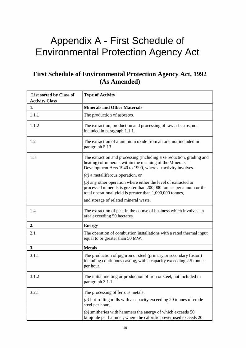
49
Appendix A - First Schedule of Environmental Protection Agency Act
First Schedule of Environmental Protection Agency Act, 1992
(As Amended)
List sorted by Class of Type of Activity
Activity Class
1. Minerals and Other Materials
1.1.1 The production of asbestos.
1.1.2 The extraction, production and processing of raw asbestos, not
included in paragraph 1.1.1.
1.2 The extraction of aluminium oxide from an ore, not included in
paragraph 5.13.
1.3 The extraction and processing (including size reduction, grading and heating) of minerals within the meaning of the Minerals Development Acts 1940 to 1999, where an activity involves-
(a) a metalliferous operation, or
(b) any other operation where either the level of extracted or processed minerals is greater than 200,000 tonnes per annum or the total operational yield is greater than 1,000,000 tonnes,
and storage of related mineral waste.
1.4 The extraction of peat in the course of business which involves an
area exceeding 50 hectares
2. Energy
2.1 The operation of combustion installations with a rated thermal input
equal to or greater than 50 MW.
3. Metals
3.1.1 The production of pig iron or steel (primary or secondary fusion)
including continuous casting, with a capacity exceeding 2.5 tonnes per hour.
3.1.2 The initial melting or production of iron or steel, not included in
paragraph 3.1.1.
3.2.1 The processing of ferrous metals:
(a) hot-rolling mills with a capacity exceeding 20 tonnes of crude
steel per hour,
(b) smitheries with hammers the energy of which exceeds 50
kilojoule per hammer, where the calorific power used exceeds 20

50
List sorted by Class of Type of Activity
Activity Class MW,
(c) application of protective fused metal coats with an input
exceeding 2 tonnes of crude steel per hour.
3.2.2 The processing of iron and steel in forges, drawing plants and rolling
mills where the production area exceeds 500 square metres, not included in paragraph 3.2.1
3.3.1 The operation of ferrous metal foundries with a production capacity
exceeding 20 tonnes per day.
3.3.2 The production, recovery, processing or use of ferrous metals in foundries having melting installations with a total capacity
exceeding 5 tonnes, not included in paragraph 3.3.1.
3.4.1 The-
(a) production of non-ferrous crude metals from ore, concentrates or secondary raw materials by metallurgical, chemical or electrolytic processes,
(b) smelting, including the alloyage, of non-ferrous metals, including
recovered products, (refining, foundry casting, etc.) with a melting
capacity exceeding 4 tonnes per day for lead and cadmium or 20
tonnes per day for all other metals.
3.4.2 The production, recovery or processing of non-ferrous metals, their
compounds or other alloys including antimony, arsenic, beryllium,
chromium, lead, magnesium, manganese, phosphorus, selenium,
cadmium or mercury, by thermal, chemical or electrolytic means in installations with a batch capacity exceeding 0.5 tonnes, not
included in paragraph 3.4.1.
3.5 The reaction of aluminium or its alloys with chlorine or its
compounds, not included in paragraph 5.13.
3.6.1 The roasting or sintering of metal ore (including sulphide ore).
3.6.2 The calcining of metallic ores in plants with a capacity exceeding
1,000 tonnes per year.
3.7 Swaging by explosives where the production area exceeds 100 square metres.
3.8 The pressing, drawing and stamping of large castings where the production area exceeds 500 square metres.
3.9 Boiler making and the manufacture of reservoirs, tanks and other sheet metal containers where the production area exceeds 500 square
metres.
4 Mineral Fibres and Glass
4.1 The processing of asbestos, and the manufacture and processing of
asbestos-based products.

51
List sorted by Class of
Activity Class
Type of Activity
4.2.1 The melting of mineral substances including the production of
mineral fibres with a melting capacity exceeding 20 tonnes per day
4.2.2 The manufacture of glass fibre or mineral fibre, not included in
paragraph 4.2.1 or 4.3
4.3 The manufacture of glass including glass fibre with a melting
capacity exceeding 20 tonnes per day or 5,000 tonnes per year.
4.4 The production of industrial diamonds
5 Chemicals
Production, for the purposes of the activities mentioned in paragraph 5.12 to 5.17, means the
production on an industrial scale by chemical processing of substances or groups of substances
mentioned in any of those paragraphs.
5.1 The manufacture of chemicals in an integrated chemical installation,
not included in paragraphs 5.12 to 5.17.
5.2 The manufacture of olefins and their derivatives or of monomers and
polymers including styrene and vinyl chloride, not included in
paragraphs 512 to 5.17.
5.3 The manufacture, by way of chemical reaction processes, of organic
or organo-metallic chemical products other than those specified in
paragraph 5.2 and not included in paragraphs 5.12 to 5.17.
5.4 The manufacture of inorganic chemicals, not included in paragraphs
5.12 to 5.17.
5.5 The manufacture of artificial fertilisers, not included in paragraphs
5.12 to 5.17.
5.6 The manufacture of pesticides, pharmaceutical or veterinary
products and their intermediates, not included in paragraphs 5.12 to
5.17.
5.7 The manufacture of paints, varnishes, resins, inks, dyes, pigments or
elastomers where the production capacity exceeds 1,000 litres per
week, not included in paragraphs 5.12 to 5.17.
5.8 The formulation of pesticides, not included in paragraphs 5.12 to
5.17.
5.9 The chemical manufacture of glues, bonding agents and adhesives,
not included in paragraphs 5.12 to 5.17.
5.10 The manufacture of vitamins involving the use of heavy metals, not
included in paragraphs 5.12 to 5.17.
5.11 The storage, in quantities exceeding the values shown, of any one or
more of the following chemicals (others than as part of any other
activity) not included in paragraphs 5.12 to 5.17 –
Methyl acrylate (20 tonnes); acrylonitrile (20 tonnes); toluene di-
isocyanate (20 tonnes; anhydrous ammonia (100 tonnes); anhydrous
hydrogen fluoride (1 tonne).

52
List sorted by Class of Type of Activity
Activity Class
5.12 The production of basic organic chemicals, such as:
(a) simple hydrocarbons (linear or cyclic, saturated or unsaturated,
aliphatic or aromatic),
(b) oxygen-containing hydrocarbons such as alcohols, aldehydes,
ketones, carboxylic acids, esters, acetates, ethers, peroxides, epoxy
resins,
(c) sulphurous hydrocarbons,
(d) nitrogenous hydrocarbons such as amines, amides, nitrous
compounds, nitro compounds or nitrate compounds, nitriles, cyanates, isocyanates,
(e) phosphorus-containing hydrocarbons,
(f) halogenic hydrocarbons,
(g) organometallic compounds,
(h) basic plastic materials (polymers, synthetic fibres and cellulose-
based fibres),
(i) synthetic rubbers,
(J) dyes and pigments,
(k) surface-active agents and surfactants.
5.13 The production of basic inorganic chemicals, such as:
(a) gases, such as ammonia, chlorine or hydrogen chloride, fluorine or hydrogen fluoride, carbon oxides, sulphur compounds, nitrogen oxides, hydrogen, sulphur dioxide, carbonyl chloride,
(b) acids, such as chromic acid, hydrofluoric acid, phosphoric acid,
nitric acid, hydrochloric acid, sulphuric acid, oleum, sulphurous
acids,
(c) bases, such as ammonium hydroxide, potassium hydroxide, sodium hydroxide,
(d) salts, such as ammonium chloride, potassium chlorate, potassium
carbonate, sodium carbonate, perborate, silver nitrate,
(e) non-metals, metal oxides or other inorganic compounds such as calcium carbide, silicon, silicon carbide.
5.14 The production of phosphorous-based, nitrogen-based or potassium-
based fertilisers (simple or compound fertilisers).
5.15 The production of basic plant health products and of biocides.
5.16 The use of a chemical or biological process for the production of basic pharmaceutical products.
5.17 The production of explosives.

53
List sorted by Class of Type of Activity
Activity Class
6. Intensive Agriculture
6.1 The rearing of poultry in installations, whether within the same
complex or within 100 metres of the same complex, where the capacity exceeds 40,000 places.
6.2 The rearing of pigs in installations, whether within the same
complex or within 100 metres of the same complex, where the
capacity exceeds-
750 places for sows in a breeding unit, or
285 places for sows in an integrated unit, or
2,000 places for production pigs.
In this paragraph-
'breeding unit' means a piggery in which pigs are bred and reared up
to 30kg in weight;
'integrated unit' means a piggery in which pigs are bred and reared
for slaughter;
'production pig' means any pig over 30kg in weight which is being fattened for slaughter;
'sow' means a female pig after its first farrowing.
7 Food and Drink
7.1 The manufacture of vegetable and animal oils and fats where the
capacity for processing raw materials exceeds 40 tonnes per day, not
included in paragraph 7.8.
7.2.1 The treatment and processing of milk, the quantity of milk received being greater than 200 tonnes per day (average value on a yearly basis).
7.2.2 The manufacture of dairy products where the processing capacity exceeds 50 million gallons of milk equivalent per year, not included in paragraph 7.2.1
7.3.1 Brewing (including cider and perry production) in installations
where the production capacity exceeds 25 million litres per year, not included in paragraph 7.8.
7.3.2 Distilling in installations where the production capacity exceeds the
equivalent of 1,500 tonnes per year measured as pure alcohol, not
included in paragraph 7.8.
7.3.3 Malting in installations where the production capacity exceeds 100,000 tonnes per year, not included in paragraph 7.8.
7.4.1 The operation of slaughterhouses with a carcass production capacity greater than 50 tones per day.

54
List sorted by Class of
Activity Class
Type of Activity
7.4.2 The slaughter of animals in installations where the daily capacity exceeds
1,500 units and where units have the following equivalents –
1 Sheep = 1 unit
1 Pig = 2 units
1 head of cattle = 5 units
and not included in paragraph 7.4.1
7.5 The manufacture of fish-meal and fish-oil, not included in paragraph 7.8
7.6 The manufacture of sugar, not included in paragraph 7.8
7.7.1 The disposal of recycling of animal carcasses and animal waste with a
treatment capacity exceeding 10 tonnes per day
7.7.2 The processing (including rendering) of animal carcasses and by-products,
not included in paragraph 7.7.1
7.8 Treatments or processes for the purposes of the production of food
products from –
(a) Animal raw materials (other than milk) with a finished product
production capacity greater than 75 tonnes per day,
(b) Vegetable raw materials with a finished product production
capacity greater than 300 tonnes per day (average value on a
quarterly basis)
8 Wood, Paper, Textiles and Leather
8.1 The production of paper pulp, paper or board (including fibre-board,
particle board and plywood) with a production capacity exceeding 20
tonnes per day.
8.2 The production of pulp from timber or other fibrous materials.
8.3 The treatment or protection of wood, involving the use of preservatives,
with a capacity exceeding 10 tonnes of wood per day.
8.4 The manufacture of synthetic fibres, not included in paragraph 5.12
8.5.1 The pre-treatment (operations such as washing, bleaching, mercerization)
or dyeing of fibres or textiles where the treatment capacity exceeds 10
tonnes per day.
8.5.2 The dyeing, treatment or finishing (including moth-proofing and
fireproofing) of fibres or textiles (including carpet) where the capacity
exceeds 1 tonne per day of fibre, yarn or textile material, not included in
paragraph 8.5.1.
8.6.1 The tanning of hides and skins where the treatment capacity exceeds 12
tonnes of finished products per day.
8.6.2 The fell-mongering of hides and tanning of leather in installations where
the capacity exceeds 100 skins per day, not included in paragraph 8.6.1.
9 Fossils Fuels

55
List sorted by Class of Type of Activity
Activity Class
9.1 The extraction, other than offshore extraction, of petroleum, natural
gas, coal or bituminous shale.
9.2 The handling or storage of crude petroleum, not included in
paragraph 9.3.1 or 9.3.2.
9.3.1 The operation of mineral oil and gas refineries.
9.3.2 The refining of petroleum or gas, not included in paragraph 9.3.1.
9.4.1 The operation of coke ovens.
9.4.2 The operation of coal gasification and liquefaction plants.
9.4.3 The production of carbon (hard-burnt coal) or electrographite by
means of incineration or graphitization.
9.4 The pyrolysis, carbonisation, gasification, liquefaction, dry
distillation, partial oxidation or heat treatment of coal, lignite, oil or
bituminous shale, other carbonaceous materials or mixtures of any
of these in installations with a processing capacity exceeding 500
tonnes per day, not included in paragraph 9.4.1 or 9.4.3.
10 Cement
10.1 The production of cement.
11 Waste
11.1 The recovery or disposal of waste in a facility, within the meaning of
the Act of 1996, which facility is connected or associated with
another activity specified in this Schedule in respect of which a
licence or revised licence under Part IV is in force or in respect of which a licence under the said Part is or will be required.
12 Surface Coatings
12.1 Operations involving coating with organo-tin compounds, not
included in paragraph 12.2.1 or 12.2.2.
12.2.1 The surface treatment of substances, objects or products using organic solvents, in particular for dressing, printing, coating, degreasing, waterproofing, sizing, painting, cleaning or impregnating, with a consumption capacity of more than 150 kg per
hour or more than 200 tonnes per year.
12.2.2 The manufacture or use of coating materials in processes with a capacity to make or use at least 10 tonnes per year of organic solvents, and powder coating manufacture with a capacity to
produce at least 50 tonnes per year, not included in paragraph 12.2.1.
12.3 The surface treatment of metals and plastic materials using an electrolytic or chemical process where the volume of the treatment 3
vats exceeds 30 m .
13 Other Activities
13.1 The testing of engines, turbines or reactors where the floor area exceeds 500 square metres.
13.2 The manufacture of integrated circuits and printed circuit boards.

56
List sorted by Class of Type of Activity
Activity Class
13.3 The production of lime in a kiln
13.4.1 The manufacture of ceramic products by firing, in particular roofing
tiles, bricks, refractory bricks, tiles, stoneware or porcelain, with a 3
production capacity exceeding 4 m and a setting density per kiln 3
exceeding 300 kg/m .
13.4.2 The manufacture of coarse ceramics including refractory bricks,
stoneware pipes, facing and floor bricks and roof tiles, not included
in paragraph 13.4.1."

57
Appendix B – Template for Additional Sheets
Template for Additional Sheets
Name of Applicant: .
Name of Premises to which Discharge Relates: .
Additional Sheets Relate to Part , Section of the Application
Form.
Total Number of Additional Sheets: .
(Sequential page Numbering Must be Included).
Where Additional Sheets are Maps / Drawings:
Map/Drawing Number , Map/Drawing Title .
Map/Drawing Number , Map/Drawing Title .
Map/Drawing Number , Map/Drawing Title .
Map/Drawing Number , Map/Drawing Title .
(Add Additional Rows as Necessary)
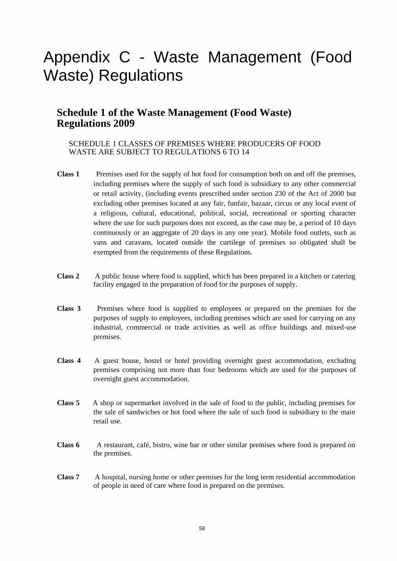
58
Appendix C - Waste Management (Food Waste) Regulations
Schedule 1 of the Waste Management (Food Waste) Regulations 2009
SCHEDULE 1 CLASSES OF PREMISES WHERE PRODUCERS OF FOOD WASTE ARE SUBJECT TO REGULATIONS 6 TO 14
Class 1 Premises used for the supply of hot food for consumption both on and off the premises,
including premises where the supply of such food is subsidiary to any other commercial
or retail activity, (including events prescribed under section 230 of the Act of 2000 but
excluding other premises located at any fair, funfair, bazaar, circus or any local event of
a religious, cultural, educational, political, social, recreational or sporting character
where the use for such purposes does not exceed, as the case may be, a period of 10 days
continuously or an aggregate of 20 days in any one year). Mobile food outlets, such as
vans and caravans, located outside the curtilege of premises so obligated shall be
exempted from the requirements of these Regulations.
Class 2 A public house where food is supplied, which has been prepared in a kitchen or catering
facility engaged in the preparation of food for the purposes of supply.
Class 3 Premises where food is supplied to employees or prepared on the premises for the
purposes of supply to employees, including premises which are used for carrying on any
industrial, commercial or trade activities as well as office buildings and mixed-use
premises.
Class 4 A guest house, hostel or hotel providing overnight guest accommodation, excluding
premises comprising not more than four bedrooms which are used for the purposes of
overnight guest accommodation.
Class 5 A shop or supermarket involved in the sale of food to the public, including premises for
the sale of sandwiches or hot food where the sale of such food is subsidiary to the main
retail use.
Class 6 A restaurant, café, bistro, wine bar or other similar premises where food is prepared on
the premises.
Class 7 A hospital, nursing home or other premises for the long term residential accommodation
of people in need of care where food is prepared on the premises.

59
Class 8 An institution providing adult, continuing or further education, a school, college or training
centre, or a university or any other third-level or higher-level institution, whether or not
supported by public funds, where food is prepared on the premises.
Class 9 State buildings where food is prepared on the premises, including:— (a) Garda stations
and other buildings; (b) Prisons and other places of detention; (c) Barracks, other
buildings and other installations (including airfields and naval yards) used for the
purposes of, or in connection with, the operation of the Defence Forces; (d) Office
buildings or other premises used for the purposes of, or in connection with, the business
of Uachtarán na h-Éireann, Dáil Éireann, Seanad Éireann, the Department of the
Taoiseach, the Office of the Tánaiste, the Department of Defence and other Government
Departments;(e) Office premises and other buildings used by local authorities.
Class 10 Canteen services where food is supplied to employees or prepared on the premises for
the purposes of supply to employees, which—(a) is situated on the site of construction,
development or refurbishment works, and (b) where the duration of such works exceeds
a period of 9 months.
Class 11 Stations, Airports, Ports, Harbours and Marinas where trains, planes, and boats which
engage in the supply of food to the public (other than food waste originating from means
of transport operating internationally) unload food waste from the transportation
medium.

60
Appendix D – Regulation 8 of the Groundwater Regulations, 2010
European Communities Environmental Objectives (Groundwater) Regulations
2010
8. (a) The direct discharge of pollutants into groundwater is prohibited;
(b) The following discharges may be permitted subject to a requirement for prior authorisation provided such discharges, and the conditions imposed, do not compromise the achievement of the environmental objectives established for the body of groundwater into which the discharge is made; (i) injection of water containing substances resulting from the operations for exploration and extraction of hydrocarbons or mining activities, and injection of water for technical reasons, into geological formations from which hydrocarbons or other substances have been extracted or into geological formations which for natural reasons are permanently unsuitable for other purposes. Such injections shall not contain substances other than those resulting from the above operations, (ii) reinjection of pumped groundwater from mines and quarries or associated with the construction or maintenance of civil engineering works, (iii) injection of natural gas or liquefied petroleum gas (LPG) for storage purposes into geological formations which for natural reasons are permanently unsuitable for other purposes, (iv) injection of natural gas or liquefied petroleum gas (LPG) for storage purposes into other geological formations where there is an overriding need for security of gas supply, and where the injection is such as to prevent any present or future danger of deterioration in the quality of any receiving groundwater, (v) discharges resulting from construction, civil engineering and building works and similar activities on, or in the ground which come into contact with groundwater. Such activities may be treated as having been authorised provided that they are conducted in accordance with general binding rules which are applicable to such activities, (vi) small quantities of substances for scientific purposes for characterisation, protection or remediation of water bodies limited to the amount strictly necessary for the purposes concerned;
(c) Reinjection of water used for geothermal purposes into the same aquifer may be permitted subject to a requirement for prior authorisation.

61
Appendix E – Estimating Hydraulic Loading
Natural Recharge from Rainfall
A certain percentage of rainfall infiltrates naturally through soils and subsoils at any given site. This is called recharge, and the fraction (percentage) of rainfall that infiltrates is commonly referred to as a “recharge coefficient” (Rc). The recharge coefficient is site-specific, and is largely dependent on soil and subsoil characteristics. Sites on low-permeability soils and sediments will have lower recharge coefficients than those on more sandy and well draining sites, simply because less rain water is able to percolate/infiltrate.
Useful reference documents for recharge estimation are the existing “Guidance on the Assessment of Impact of Groundwater Abstractions” (Working Group on Groundwater (WGGW) 2005a, 2005b) and Misstear et al. (2009)
5. Prepared in the context of WFD
implementation in Ireland, these documents incorporate tables of recharge coefficients for different hydrogeological settings that are specific to Ireland, and which are rooted in the extensive groundwater vulnerability mapping carried out by the GSI.
The documents also include step-by step methods for determining which recharge coefficient would be appropriate for a given site, using information from these sources:
Rainfall (R) – from Met Éireann (www.met.ie) – 30-year annual average rainfall map for 1961–1990 or 1971–2000. Use the data from the gauging station which is in closest proximity to the site from which the discharge is to take place;
Potential Evapotranspiration (PE) – from Met Éireann – national map; Soil drainage type – from Teagasc – distinguishes between poorly drained and
well drained soils; Groundwater vulnerability – from the GSI – national groundwater vulnerability
map; Subsoil permeability – from the GSI – national map of subsoil permeability.
Table 1 reproduces the recommended recharge coefficients described by the GWWG (2005a,b) and Misstear et al. (2009).
5
WGGW (2005a). Guidance on the Assessment of the Impact of Groundwater Abstractions. Guidance Document No. GW5. Paper by the Working Group on Groundwater. March 2005.
WGGW (2005b). Methodology for Risk Characterisation of Ireland’s Groundwater. Guidance Document No. GW8. Paper by the Working Group on Groundwater. March 2005.
Gill, L.W., O’Luanaigh, N., Johnston, P.M., Misstear, B.D.R, O`Suilleabhain, C. (2009). Nutrient loading on subsoils from on-site wastewater effluent, comparing septic tank and secondary treatment systems. Water Research 43, 2739-2749.

62
Table 1: Recharge Coefficients Used in Recharge Estimation
Vulnerability
Hydrogeological Setting
Recharge Coefficient (Rc)
Category
(references to soils relate to Teagasc soil mapping) Min Inner Max
(%) Range (%)
1.i Areas where rock is at ground surface 60 80-90 100
1.ii Sand/gravel overlain by ‘well drained’ soil 60 80-90 100
Sand/gravel overlain by ‘poorly drained’ (gley) soil
Extreme
1.iii Till overlain by ‘well drained’ soil 45 50-70 80
1.iv Till overlain by ‘poorly drained’ (gley) soil 15 25-40 50
1.v
Sand/ gravel aquifer where the water table is ≤ 3 m below 70 80-90 100 surface
1.vi Peat 15 25-40 50
2.i Sand/gravel aquifer, overlain by ‘well drained’ soil 60 80-90 100
2.ii
High permeability subsoil (sand/gravel) overlain by ‘well 60 80-90 100
drained’ soil
2.iii High permeability subsoil (sand/gravel) overlain by
‘poorly drained’ soil
High 2.iv Moderate permeability subsoil overlain by ‘well drained’ 35 50-70 80
soil
2.v
Moderate permeability subsoil overlain by ‘poorly drained’ 15 25-40 50
(gley) soil
2.vi Low permeability subsoil 10 23-30 40
2.vii Peat 0 5-15 20
3.i
Moderate permeability subsoil and overlain by ‘well drained’ 25 30-40 60 soil
3.ii Moderate permeability subsoil and overlain by ‘poorly
10 20-40 50 Moderate drained’ (gley) soil
3.iii Low permeability subsoil 5 10-20 30
3. iv Basin peat 0 3-5 10
Low 4.i Low permeability subsoil 2 5-15 20
4.ii Basin peat 0 3-5 10
5.i High Permeability Subsoils (Sand & Gravels) 60 90 100
5.ii Moderate Permeability Subsoil overlain by well drained soils 25 60 80
High to Low 5.iii
Moderate Permeability Subsoils overlain by poorly drained 10 30 50
soils
5.iv Low Permeability Subsoil 2 20 40
5.v Peat 0 5 20
Made Ground 6. Disturbed soils in built-up areas 10 20 50

63
An example of recharge estimation is provided below:
Example 1: Site involving an onsite waste water treatment system (OSWTS) with a
percolation area of 1,000 m2.
The site location is checked against information from the above-listed sources of information:
Groundwater vulnerability = high (from GSI vulnerability map);
Subsoil permeability = moderate (from GSI subsoil permeability map);
Soil type = well drained soils (from Teagasc soil type map);
Rainfall (R) = 820 mm/yr (from Met Éireann).
Potential evapotranspiration (PE) = 500 mm/yr (from Met Éireann). Actual
evapotranspiration (AE) = PE x 0.95 = 0.95 x 500 = 475 mm/yr.
From Table 1, the inner range of expected recharge coefficients (Rc) = 50-70%; 60% selected on basis of site (soil/subsoil) characteristics.
Effective Rainfall (ER) = R–AE = 820-475 = 345 mm/yr.
Rc = 60%.
Therefore, recharge = 345 x 0.6 = 207 mm/yr = 0.21 m/yr.
For a percolation area of 1,000 m2, the total estimated recharge (from rainfall)
would be 0.21 m/yr x 1,000 m2 = 210 m
3/yr.
Total Estimated Hydraulic Loading The total estimated hydraulic loading rate is given by the following equation:
Total hydraulic loading = Discharge rate + Natural recharge rate
Example 2: Total Hydraulic Loading combining loading from Examples 1 and 2;
Discharge rate = 4.2 m3/day = 1,533 m
3/yr;
Natural recharge rate = 210 m3/yr (or 0.58 m
3/d);
Total Estimated Hydraulic Loading = 1,533 + 210 = 1,743 m3/yr = 4.77 m
3/d.

64
Hydraulic Loading from Recharge Basins or Ponds Potential infiltration from discharge activities that involve recharge basins or ponds (such as
integrated constructed wetlands - ICWs) have to be estimated slightly differently from above
since there is no treatment system for the effluent per se, but rather, effluent infiltrates
through the base of basins/ponds as a function of:
Vertical gradient (head of water);
Subsoil permeability. In reality, the base of the basins/ponds may develop a lower-permeability “mat” due to
silting, but for initial estimates of infiltration, gradient and subsoil permeability drive the
infiltration capacity.
Hydraulic loading from basin/pond = Area x Vertical gradient x
Subsoil permeability
Example 3: ICW with a one hectare pond. The base of the pond has been lined with a 0.75 m thick clayey subsoil with an average permeability (field-saturated hydraulic
conductivity) of 1x10⁻⁸
m/s.
Average depth (head) of water/waste water in pond = 0.2 m (measured
onsite); Vertical hydraulic gradient = (0.75+0.2)/0.75 = 1.27;
Expected Hydraulic Loading from Pond = 10,000 m2 x 1.27 x 1x10
-8 m/s x 86,400
= 11 m3/d.

65
Appendix F - Infiltration Capacity
Even though a discharge rate or loading can be defined, there is no guarantee that the planned effluent quantities can actually be percolated on account of the hydrogeological characteristics of the site. The quantity that can be physically percolated over a planned area in the long term reflects the site’s inherent “infiltration capacity”. The term “infiltration capacity” is sometimes also referred to as a “long-term acceptance rate”, which is the quantity that can infiltrate from a particular effluent treatment system without clogging of subsoils or water-logging at the surface. One of the goals of a Tier 1, 2 or 3 assessment is to estimate the infiltration capacity of a site, which can be achieved through field testing (e.g. T-tests) or calculations using permeability values of the underlying geological materials. In the context of Irish hydrogeology, the reference to permeability relates to both subsoils and bedrock aquifers. Infiltration capacity at any given site may be compromised if:
Clay layers (even thin clay bands) are present beneath the percolation area;
The groundwater table is naturally shallow (close to the surface), even seasonally;
The subsoils above low-permeability bedrock are very thin; and
In the case of OSWTSs, a biomat is formed due to high BOD of the wastewater (which lowers the permeability of the geological materials surrounding the OSWTS).
The function of the biomat is crucial to the understanding of the design loading rates set out in the EPA CoP, where the loading rates are based on the interaction of the biomat and underlying subsoil hydraulic conductivity.
Regarding the permeability of geological materials, the degree to which permeability has to be quantified or tested (both in subsoils and aquifers) depends on the risk of impact posed by the proposed development, as described in Section 4 of the main report. For Tier 1 assessment, T-tests will mostly be sufficient, using guidance in the EPA CoP on effluent disposal from single houses (EPA, 2009). For Tier 2 assessment, T-tests may be sufficient, although permeability estimation from grain-size distribution and falling/rising head tests may also be required. For Tier 3 assessment, in-situ and/or laboratory testing is likely to be required, as well as test pumping of the aquifer.
A related concept that may be important at some sites is groundwater mounding. When effluent enters groundwater, groundwater levels may rise and develop a mound beneath the percolation area. In broad terms, the height of mounding (and risk of ponding) is a function of the permeability relationships of subsoils and aquifers, the contrast between them, and the effluent percolation rate and volume.
A more permeable or transmissive aquifer has greater capacity to transmit percolating water away from the source of percolation and therefore the maximum height of the mound will be less. Mounds that form beneath a percolation area will change in size and shape with time as a function of seasonal climatic changes and changes in effluent quantities with time. Mounds that intersect ground surface will cause localized ponding or flooding and increased surface runoff.

66
There are few instances where mounding is likely to be a significant concern, however, some Tier 2 and 3 assessments may have to look at the potential for mounding, in which case simple, analytical techniques exist to predict mounding using site specific hydrogeological data, although more detailed investigations may be required in circumstances where the hydraulic loading is high and the infiltration capacity is limited.
Infiltration Capacity and Loading from OSWTS
Sites where the saturated subsoil permeability is estimated to be 1x10⁻⁸
m/s or lower are
unlikely to be suitable for percolation of effluent, even for small-scale OSWTSs, as the effluent cannot physically percolate underground in sufficient quantities to avoid ponding at the surface. As most discharge to groundwater applications are expected to involve OWSTSs, estimates of infiltration capacity will mostly be limited to results from T-tests in trial holes.
From the EPA CoP for OSWTSs for single houses (EPA, 2009), T-values should fall in the range between 3 and 50 for a site to be considered suitable for percolation of septic tank effluent or between 3 and 75 for the discharge of secondary (or tertiary) treated effluent. The
appropriate design hydraulic loading rates in terms of litres per m2 plan area per day (l/m
2/d)
depends upon the quality of effluent discharged to the subsoil (septic tank or secondary treated) and whether the effluent is discharged by gravity to percolation trenches or pumped to a distribution manifold (EPA, 2009a). It should be noted that when effluent is discharged by gravity to the percolation trenches, the CoP states the hydraulic loading rates in terms of the base of the trench (not the overall plan area of the percolation area). The LTARs (Long Term Acceptance Rates) stated in this report have been calculated on the basis of the effluent loading onto the overall plan area of the percolation area. The LTAR is defined as, “the amount of pre-treated effluent which the system can infiltrate during its lifetime without
water logging or clogging” in units, l/m2/d (Gill, 2006).
While T-values remain the primary metric for determining infiltration capacity of sites involving OSWTS, Tier 2 and 3 assessments require hydraulic loading calculations that make use of site-specific subsoil permeability values, as described in Section 4 of the main document. The determination of permeability is a relatively complex field with several different approaches available (e.g., grain size analyses, falling head tests in piezometers, and laboratory techniques). The different methods each express percolation rates with their own unique coefficient of hydraulic conductivity value. The standard falling head T-test carried out on-site in Ireland, however, does not express the percolation value in terms of hydraulic conductivity but the mean time for the water level to drop 25 mm over the test. Research carried out by Mulqueen and Rodgers (2001) on the Irish T-test procedure concluded that it would be more rigorous to convert the T-values into field saturated hydraulic conductivity (kfs) values. This approach was adopted because, while percolation times recorded in consecutive tests in the same hole generally increase, kfs values remain relatively constant. The kfs is then expressed as the inverse of the percolation rate times a constant, thus allowing the percolation rate to be directly related to the kfs of the soil (Mulqueen and Rodgers, 2001). For a 0.3 m x 0.3 m trial hole,
k fs 4.2
(m / d
) tm
where tm is the T-value (i.e. average time to fall 25 mm). Use of this equation for T values outside of the range 3-75 is not recommended.

67
Table E.2 provides a summary of the approximate relationships between T-values, permeability and long-term acceptance rates for small waste water treatment systems, as reported by Gill (2006). As such, Table E.2 is a useful reference, particularly for Tier 1 assessments. Table E3 gives estimated permeability values for the subsoils mapped by the GSI as part of the vulnerability mapping process. Table E.3 Estimated permeability ranges for subsoils
Subsoil type Permeability
m/d (BS5950)
(m/s)
GRAVEL >5
SAND (5x10⁻⁵
)
SILT 1x10
-2 to 5
(1x10⁻⁷
to 5x10⁻⁵
)
5x10⁻³
to 5x10⁻¹
SILT/CLAY
(5x10⁻⁸
to 5x10⁻⁶
)
<5x10⁻³
CLAY
(<5x10⁻⁸
)

68
Table E.2: Approximate Relationships between T-values, Permeability and Long-term Acceptance Rates
T-value 1 Design loading rate for effluent
(LTAR) (l/m2/d)
Kfs
m/d Septic tank Secondary treated Septic tank Secondary Gravity
2 gravity
2 pumped treated
pumped
< 3 > 1.4 Direct infiltration not authorised
3 to 20 1.4 to 0.21 3.33 10 4 20
20 to 40 0.21 to 0.11 3.33 5 4 10
40 to 50 0.11 to 0.08 3.33 5 4 5
50 to 75 0.08 to 0.06 not permitted 3.2 not permitted 3
> 75 < 0.06 Discharge to ground not authorised
1 –T-value ranges converted into equivalent permeabilities using the Mulqueen and Rodgers (2001) equation. 2 - All LTARs are based on plan area of percolation area (i.e. not trench base for effluents discharged by gravity).

69
Spatial Considerations To check the percolation area needed for a given infiltration capacity, the following equation can be applied:
A = Q/Inf
Where,
A = percolation area needed (m2);
Q = total hydraulic loading rate (m3/d);
Inf = infiltration capacity (l/m2/d or m
3/m
2/d).
Alternatively, if the applicant has a limited area available for an infiltration system, the
infiltration capacity that must be verified from field testing or permeability estimates can be
calculated by simply re-arranging the above equation, as follows
Inf = Q/A
Where,
Inf = infiltration rate (m/d) that must be field-tested;
Q = discharge volume/rate (m3/d);
A = area (m2) available for infiltration/percolation.
The latter is not an uncommon situation, particularly for commercial enterprises operating within confined property boundaries.
Example:
Total estimated discharge rate = 39 m3/d;
Land available as a percolation area = 1,200 m2, or 40 m x 30 m;
Therefore, Inf = 39/1200 = 0.032 m/d, 32 mm/d, as the infiltration rate that has to be verified over the planned percolation area. Note – A value of 32 mm/d is very large, but is the required infiltration capacity where there is a constraint that only 1,200 m
2 is available as an infiltration area. Until verified
through field testing, Inf therefore remains theoretical. Field testing may be carried out as T-tests, or calculations made using permeability values.
Preferential Flow Pathways Preferential pathways can be an important site feature that can influence both the hydraulic and chemical loading to groundwater, whereby infiltration capacity is increased and the attenuation potential is reduced. Preferential pathways can be of many different types. They can be macropores formed by root zones or burrows created by fauna, or they can be cracks and fractures in subsoils that result from geological processes (e.g., weathering in glacial tills). They can also represent the inherent heterogeneity (or variability) of subsoil textures, or disturbances caused by tillage or excavation.

70
Any subsoil investigation should include a visual examination for the presence of preferential pathways. This is best accomplished in test trenches where subsoils are exposed. It may not be possible to directly quantify the influence of preferential pathways at any given site, but where they are observed, they should be noted and described in the site conceptual model.
A useful review of preferential pathways in the Irish context is provided by Daly (2002) who concludes that the potential for “bypass flow” would be particularly significant in areas where thickness of soils and subsoils are thin (<2 m) – e.g. in areas of extreme groundwater vulnerability. Additionally, the Irish Soil map of 1980 (Gardiner and Radford, 1980) provides lists of soil associations in which physical characteristics are “conducive to preferential flow”.

71
Appendix G - Conceptual Hydrogeological Models
Introduction
This appendix describes conceptual hydrogeological models and their importance in site assessment. It also highlights two important and specific hydrogeological environments that are common in Ireland; poorly productive aquifers and karstified limestone aquifers. A conceptual hydrogeological model is a simplified representation or working description of how a real hydrogeological system is believed to behave.
A good conceptual model can help to define how pollutants migrate from a source to a receptor. The model can be simple or complex, depending on the site and the discharge activity at hand. It may be purely descriptive in nature or it may incorporate illustrations in the form of geological cross-sections, drawings, maps, photographs, etc. Conceptual models may also include tabulations and basic calculations such as groundwater flow calculations and water balances, in which case they are described as quantitative in nature. An important point to note is that conceptual models only need to be as complex as the site itself or commensurate with the degree of risk of impact on receptors.
Developing a Conceptual Understanding Three simple diagrams have been compiled to illustrate the value and complexity of a site specific conceptual groundwater model.
The beginning of the process of compiling a conceptual model is to gather and correlate the existing information. Figure G1A shows a sketch map of part of a valley. A river flows
along the valley floor. A spring on the edge of the river flood plain feeds water through a small wetland to the river. A group scheme water supply borehole is located adjacent to the
spring just above the flood plain. It is proposed that a farm will discharge wastewater into the ground on the valley sides. The farm has its own water supply borehole. A house above the
farm has another private supply borehole. Groundwater level measurements have been made,
and the levels in metres above datum are shown in red on the map. The groundwater levels are as follows: private borehole is 27 mOD; farm borehole is 21 mOD; group scheme supply
water level is 9 mOD; the spring level is 8 mOD; and the river is 6 mOD. Figure G1B shows the obvious interpretation of this information in plan view or from a surface perspective. The
groundwater gradient, and flow direction is from the valley sides towards the river in the valley floor. The proposed farm discharge to groundwater is directly up-gradient of the group
scheme borehole, the spring and wetland, and the river. Therefore, it appears that there is an obvious potential pathway for flow by gravity underground between the site of the proposed
discharge or ‘Source’, and three receptors, when viewed in a two dimensional plan views, or
from the surface.

72
Figure G1 Plan view of a rural area showing water level contours and a pollution plume (Source: David Ball)
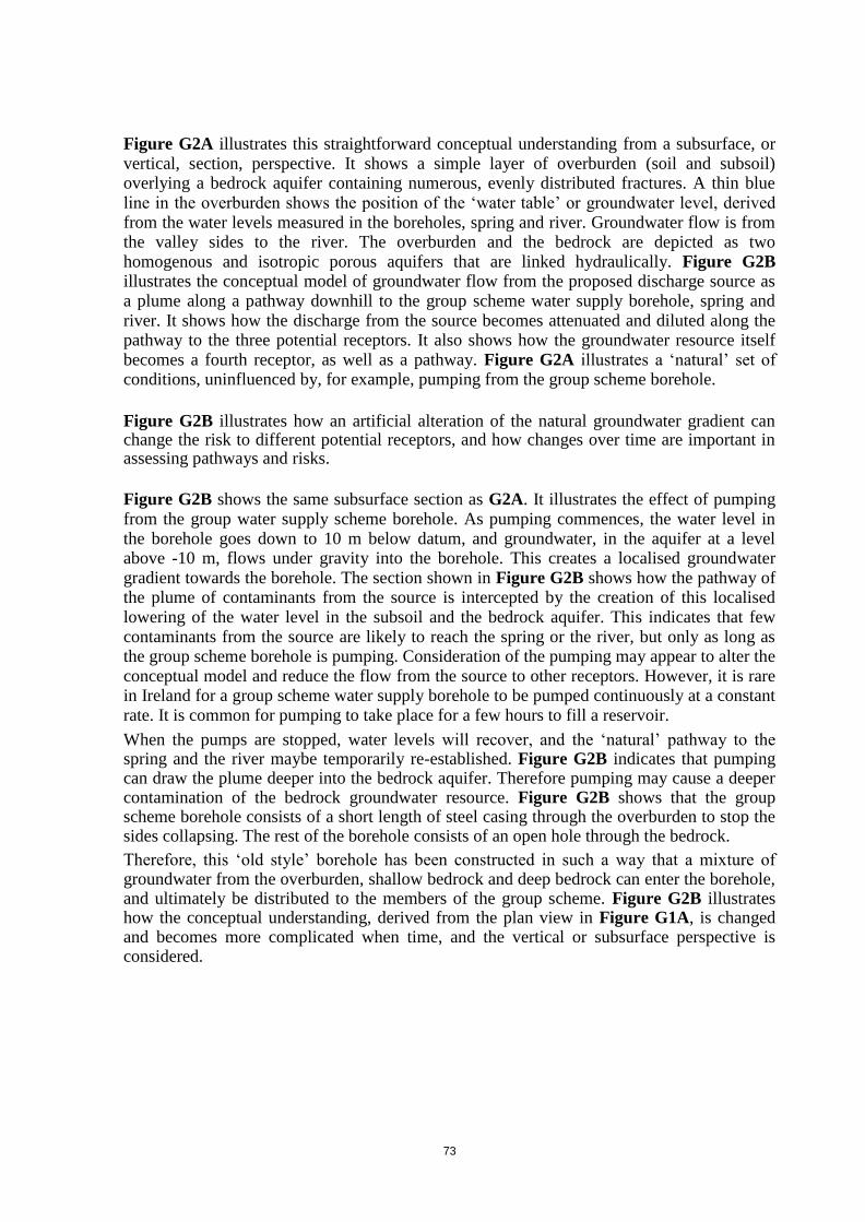
73
Figure G2A illustrates this straightforward conceptual understanding from a subsurface, or vertical, section, perspective. It shows a simple layer of overburden (soil and subsoil) overlying a bedrock aquifer containing numerous, evenly distributed fractures. A thin blue line in the overburden shows the position of the ‘water table’ or groundwater level, derived from the water levels measured in the boreholes, spring and river. Groundwater flow is from the valley sides to the river. The overburden and the bedrock are depicted as two homogenous and isotropic porous aquifers that are linked hydraulically. Figure G2B illustrates the conceptual model of groundwater flow from the proposed discharge source as a plume along a pathway downhill to the group scheme water supply borehole, spring and river. It shows how the discharge from the source becomes attenuated and diluted along the pathway to the three potential receptors. It also shows how the groundwater resource itself becomes a fourth receptor, as well as a pathway. Figure G2A illustrates a ‘natural’ set of conditions, uninfluenced by, for example, pumping from the group scheme borehole.
Figure G2B illustrates how an artificial alteration of the natural groundwater gradient can change the risk to different potential receptors, and how changes over time are important in assessing pathways and risks.
Figure G2B shows the same subsurface section as G2A. It illustrates the effect of pumping
from the group water supply scheme borehole. As pumping commences, the water level in the borehole goes down to 10 m below datum, and groundwater, in the aquifer at a level above -10 m, flows under gravity into the borehole. This creates a localised groundwater gradient towards the borehole. The section shown in Figure G2B shows how the pathway of the plume of contaminants from the source is intercepted by the creation of this localised lowering of the water level in the subsoil and the bedrock aquifer. This indicates that few contaminants from the source are likely to reach the spring or the river, but only as long as the group scheme borehole is pumping. Consideration of the pumping may appear to alter the conceptual model and reduce the flow from the source to other receptors. However, it is rare in Ireland for a group scheme water supply borehole to be pumped continuously at a constant rate. It is common for pumping to take place for a few hours to fill a reservoir. When the pumps are stopped, water levels will recover, and the ‘natural’ pathway to the spring and the river maybe temporarily re-established. Figure G2B indicates that pumping can draw the plume deeper into the bedrock aquifer. Therefore pumping may cause a deeper contamination of the bedrock groundwater resource. Figure G2B shows that the group scheme borehole consists of a short length of steel casing through the overburden to stop the sides collapsing. The rest of the borehole consists of an open hole through the bedrock. Therefore, this ‘old style’ borehole has been constructed in such a way that a mixture of groundwater from the overburden, shallow bedrock and deep bedrock can enter the borehole, and ultimately be distributed to the members of the group scheme. Figure G2B illustrates how the conceptual understanding, derived from the plan view in Figure G1A, is changed and becomes more complicated when time, and the vertical or subsurface perspective is considered.

74
Figure G2 Cross-section showing the effective of pumping well on the development of a pollution plume (Source: David Ball)
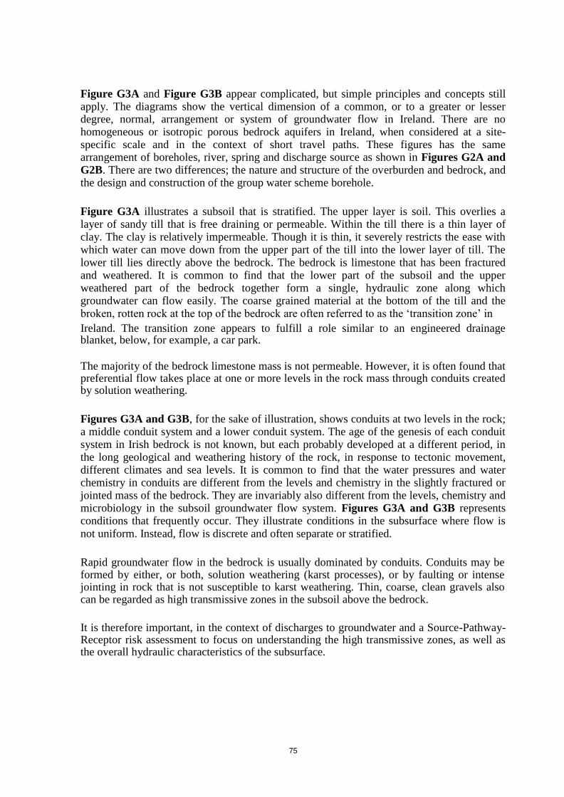
75
Figure G3A and Figure G3B appear complicated, but simple principles and concepts still apply. The diagrams show the vertical dimension of a common, or to a greater or lesser degree, normal, arrangement or system of groundwater flow in Ireland. There are no homogeneous or isotropic porous bedrock aquifers in Ireland, when considered at a site-specific scale and in the context of short travel paths. These figures has the same arrangement of boreholes, river, spring and discharge source as shown in Figures G2A and G2B. There are two differences; the nature and structure of the overburden and bedrock, and
the design and construction of the group water scheme borehole.
Figure G3A illustrates a subsoil that is stratified. The upper layer is soil. This overlies a
layer of sandy till that is free draining or permeable. Within the till there is a thin layer of clay. The clay is relatively impermeable. Though it is thin, it severely restricts the ease with which water can move down from the upper part of the till into the lower layer of till. The lower till lies directly above the bedrock. The bedrock is limestone that has been fractured and weathered. It is common to find that the lower part of the subsoil and the upper weathered part of the bedrock together form a single, hydraulic zone along which groundwater can flow easily. The coarse grained material at the bottom of the till and the broken, rotten rock at the top of the bedrock are often referred to as the ‘transition zone’ in Ireland. The transition zone appears to fulfill a role similar to an engineered drainage blanket, below, for example, a car park.
The majority of the bedrock limestone mass is not permeable. However, it is often found that preferential flow takes place at one or more levels in the rock mass through conduits created by solution weathering.
Figures G3A and G3B, for the sake of illustration, shows conduits at two levels in the rock; a middle conduit system and a lower conduit system. The age of the genesis of each conduit system in Irish bedrock is not known, but each probably developed at a different period, in the long geological and weathering history of the rock, in response to tectonic movement, different climates and sea levels. It is common to find that the water pressures and water chemistry in conduits are different from the levels and chemistry in the slightly fractured or jointed mass of the bedrock. They are invariably also different from the levels, chemistry and microbiology in the subsoil groundwater flow system. Figures G3A and G3B represents conditions that frequently occur. They illustrate conditions in the subsurface where flow is not uniform. Instead, flow is discrete and often separate or stratified.
Rapid groundwater flow in the bedrock is usually dominated by conduits. Conduits may be formed by either, or both, solution weathering (karst processes), or by faulting or intense jointing in rock that is not susceptible to karst weathering. Thin, coarse, clean gravels also can be regarded as high transmissive zones in the subsoil above the bedrock.
It is therefore important, in the context of discharges to groundwater and a Source-Pathway-Receptor risk assessment to focus on understanding the high transmissive zones, as well as the overall hydraulic characteristics of the subsurface.

76
Figure G3 Cross-section in a karstified showing the role of the subsoil and conduits in the limestone (Source: David Ball)

77
Figures G1, G2 and G3 illustrated how the river, spring and the group water supply scheme borehole were each potential specific receptors, and how the groundwater resource was a fourth more general receptor. Figure G2B showed how pumping from the water supply borehole could temporarily or permanently alter the assessment of risk depending upon duration of pumping. Figures G3A and G3B illustrate how the conceptual model shown in Figure G2B is radically altered by a combination of a properly constructed water supply borehole and a heterogeneous aquifer with conduit flow systems.
The EPA supported the publication of the IGI Guidelines on water well construction (IGI,
2007). A proper, modern water supply borehole must be constructed in such a way as to prevent the ingress of shallow groundwater that is either susceptible or potentially vulnerable
to contamination. This is achieved by the installation of a pump chamber casing around which the annulus (the gap between the outside of the casing and the inside of the bored
hole) is fully sealed by an injected cement grout. The group water supply scheme borehole in Figure G3A and Figure G3B is shown with a blue water well grade PVC pump chamber
casing down from the surface to just above the lower conduit system in the limestone
bedrock. The cement grout filled annulus is highlighted in red outside the blue casing. The diagram shows how water can only enter the borehole from below the casing and grout seal.
Figure G3B illustrates the pumping arrangements for the water supply borehole. It shows
the pump inside the pump chamber casing, and, as the water level during pumping cannot be
drawn down below the pump, the pumping water level (given for example as -10 m) is never below the bottom of the casing. It shows how the water pumped from the borehole is drawn
from the lower conduit, and how the water from the overburden, transition zone and middle conduit cannot migrate down to the inflow level at the base of the pump chamber casing.
Figure G3B also goes further to illustrate how pumping, a borehole constructed in this
manner, creates a draw down in the water pressure in the lower conduit system, but does not create a draw down in the water pressure in the middle conduit, and transition zone or the
water table in the till above the clay. Figure G3B illustrates how the Pathway of the plume of contaminants from the Source is not altered by the pumping. Figure G3B has been drawn
to show how a properly constructed water supply borehole, down gradient of a proposed discharge Source, need not be a Receptor, and therefore how a proposed discharge to
groundwater can be permitted above a water supply borehole.
Recommended Approach All site assessments associated with discharge to groundwater activities should be accompanied by conceptual models. Tier 2 and Tier 3 assessments should include the preparation (by the applicant) of a conceptual model report, which would usually be illustrated by cross-sections, such as those exemplified in Figure G.4 (sourced from Conroy, 2010) and Figure G.5 (CDM, 2010).
Cross sections to illustrate a conceptual model are vital to achieve a proper understanding of the risk of impact at a given site. The challenge of drawing a credible cross section emphasizes the need to understand the Pathway linking the Source and the Receptor. It highlights the need to gather appropriate information on groundwater flow above the Source, between the Source and the Receptor and at the Receptor. In other words, a Pathway starts as flow up-gradient of the Source, and not just at the source. Compiling a section also draws

78
attention to how the risk to various receptors may change as a result of natural seasonal variations, or artificial changes induced by human interventions and the adequate or inadequate construction of water supply sources.
The recommended approach is to focus on the Pathway(s).
Examples of important questions, depending on the circumstances, to be addressed are: Is there sufficient information on the hydrogeology, and in particular the Pathway?
What do water levels, or water chemistry/microbiology analyses from
boreholes represent in the vertical dimension?
Is there a temporary or permanent shallow groundwater flow system in the subsoil?
Is there a risk of a direct input occurring?
Can the effluent move away underground without ponding at the surface?
What and where are the potential receptors?
How would pollutants reach a receptor; i.e. the pathways?
Will substances in the effluent be adequately attenuated before reaching a receptor?
How quickly can an impact occur?
What should a groundwater monitoring network look like?
Are the proposed monitoring network boreholes properly designed and constructed to provide accurate, appropriate information?
Are potential seasonal variations sufficiently accounted for?
Site context – are there other nearby pollution sources?
A useful reference document on the development of conceptual models is the EC-published document entitled “Guidance on Risk Assessment and the Use of Conceptual Models for Groundwater” (CIS, 2010).
Conceptual model development is an iterative process as indicated by Figure G.6. Development should start at the planning phase of a discharge activity to ensure that all relevant information is considered and prepared in an application process.

79
Figure G.4 – Example
of a Conceptual Hydrogeological Cross-Section

80
Figure G. 5 – Example of a Conceptual Hydrogeological Cross-section in a Poorly Productive Bedrock Aquifer

81
Figure G.6 – Principles of Conceptual Model Development
As the site assessment is carried out, the conceptual model should be reviewed as new data and information become available, and as the hydrogeological understanding of the site progresses. Its development and refinement is a function of data availability and subsequent findings during field investigations. As much as summarising what is conceptually understood about a site, the conceptual model is equally important in highlighting what is not understood or inadequately quantified. The model therefore serves to steer the site assessment work that may be required.
Poorly Productive Aquifers Specific hydrogeological environments in Ireland that should receive particular attention in conceptual models and site investigations are bedrock aquifers classified by the GSI as “poorly productive”. These are highlighted because they cover nearly two-thirds of the total land area of the republic.
Poorly productive aquifers are bedrock aquifers that exhibit low-permeability characteristics in terms of groundwater flux and hydraulic behaviour. As defined by the GSI, PPAs include aquifer categories Pu, Pl, and Ll (DELG/EPA/GSI, 1999; GSI, 2006), as follows:
Pu – bedrock aquifers which are generally unproductive;
Pl – bedrock aquifers which are generally unproductive except for local zones;
Ll - bedrock aquifers which are moderately productive only in local zones.
Although PPAs are generally not regarded as important sources of water for public water supply (although occasionally high-yielding wells can be drilled in fault zones), they are nonetheless believed to be environmentally significant in terms of delivering water and associated pollutants to rivers and lakes via shallow groundwater pathways (EPA, 2006). For this reason, the EPA has incorporated PPAs into its long-term WFD monitoring programme, but with a focus and means of monitoring which are very different to those in other more regionally important aquifers.

82
Their key hydrogeological characteristics and features, as well as a suggested groundwater monitoring approach, was documented as part of a national study of PPAs (EPA, 2010). As summarised in Figure G.7, PPAs include four potential pathways for groundwater movement:
Subsoils;
A “transition zone” between subsoils and underlying bedrock;
Shallow bedrock;
Deeper bedrock. Figure G.7 Subsurface Pathways and Monitoring Targets

83
Subsoils are represented by lithologies such as glacial till or alluvial sediments along stream courses. The “transition zone” (TZ) is the boundary between subsoils and fractured bedrock. Its physical appearance is often “rubbly”, represented by broken pieces of rock and a dense network of shallow fractures which may be infilled to varying degrees by subsoil and/or weathered bedrock.
The TZ can transmit relatively large quantities of groundwater quickly (driven by physical gradients) and has therefore a particular relevance to a discharge to groundwater activity. Depending on the position within a catchment, the TZ (if present at a site) may or may not be saturated with water. At higher positions within a catchment, the TZ can dry up periodically during periods of no rainfall and, as such, would have greater capacity to move effluent away from a site. In contrast, closer to rivers and streams, the TZ may be filled with water all year around, which in theory would reduce its hydraulic capacity to move percolating effluent away. The latter is a function of the hydraulic conductivity and transmissivity of the TZ which can be field tested as described in Section 4 of this guidance document.
The shallow bedrock zone occurs immediately beneath the TZ. It may or may not be weathered, and the fractures and joints in the rock may or may not be clogged with residual clays. Like the TZ, shallow bedrock may be temporarily (seasonally) dry.
Deep bedrock is conceptually a deeper section in which fractures and fissures transmit groundwater and support baseflow of streams all year around. Conceptually, there are fewer (or less frequent) fractures and fissures with increasing depth, but this is not always the case. Groundwater flow in PPAs takes place through fractures and fissures, and is characterised by low transmissive and storage properties. Groundwater occurrences and flow patterns are determined by heterogeneities associated with the frequency and geometry of related fractures and fissures.
It is important to note that not all pathways may be present or apparent at all locations within a PPA catchment. For this reason, sites that involve PPAs should include site investigation to describe site-specific pathways and permeability of respective pathways (i.e. through hydraulic testing of boreholes and/or wells).
Karstified Limestone Aquifers A second hydrogeological environment in Ireland that merits particular attention is the limestone karst. Karstic limestone aquifers are characterised by groundwater flow through underground solution cavities and cave systems in addition to flow through fissures and along bedding planes. Karstified limestone aquifers have been classified by the GSI as “Rkc” aquifers – regionally important limestone aquifers that are dominated by conduit flow – and as “Rkd” aquifers - regionally important limestone aquifers where flow is more diffuse through fractures and fissures. Both aquifer types serve as important sources of public water supply, in many counties, but principally in central and western parts of the country, including Mayo, Roscommon, Galway, Clare.
Groundwater flow in karstified aquifers is notoriously unpredictable, both in terms of flow rates and directions. Zones of contributions of discharge points such as springs can therefore be difficult to define, and extensive tracer tests may be required to prove hydraulic connections between recharge and discharge points. The input of an experienced karst hydrogeologist is recommended for Tier 2 and 3 site assessments in such aquifers Figure G8 illustrates the underground pathway of a pollution incident on a limestone pavement.

84
Figure G.8 – Pollution Incident on Limestone Pavement
The vertical passage of the pollutant follows larger fissures in the limestone, without the delaying factor and attenuation of the soil, thereby creating more rapid transport of the pollutant to the groundwater and ultimately the spring or stream.

85
MacDonald Ireland Mott MacDonald Ireland 5 Eastgate Avenue South Block Eastgate Rockfield Little Island Dundrum Co.Cork Dublin 16
T: 021 4809800 T: 01 291 6700 F: 021 4809801 F: 01 291 6747