Directory chapter 01 Miniature D connectors, 1.27 mm · PDF fileillings Board dr Male...
24
01 . 01 har·mik Miniature D connectors, 1.27 mm pitch Page I/O connectors . . . . . . . . . . . . . . . . . . . . . . . . . . . . . . . . . . . . . . . . . . . . . . . . . 01.02 Pin and socket Technical characteristics . . . . . . . . . . . . . . . . . . . . . . . . . . . . . . . . . . . . . . . . 01.04 Connectors with straight solder pins . . . . . . . . . . . . . . . . . . . . . . . . . . . . . . . 01.05 Connectors with right angled solder pins . . . . . . . . . . . . . . . . . . . . . . . . . . . 01.07 Connectors with IDC flat cable termination . . . . . . . . . . . . . . . . . . . . . . . . . . 01.09 Connectors with IDC discrete wire termination . . . . . . . . . . . . . . . . . . . . . . . 01.10 Bellows Technical characteristics . . . . . . . . . . . . . . . . . . . . . . . . . . . . . . . . . . . . . . . . 01.12 Connectors with straight solder pins . . . . . . . . . . . . . . . . . . . . . . . . . . . . . . . 01.13 Connectors with right angled solder pins . . . . . . . . . . . . . . . . . . . . . . . . . . . 01.14 Connectors with IDC discrete wire termination . . . . . . . . . . . . . . . . . . . . . . . 01.15 Hoods Technical characteristics . . . . . . . . . . . . . . . . . . . . . . . . . . . . . . . . . . . . . . . . 01.16 Hoods for pin and socket male connectors . . . . . . . . . . . . . . . . . . . . . . . . . . 01.17 Hoods for bellows male connectors . . . . . . . . . . . . . . . . . . . . . . . . . . . . . . . 01.19 Accessories . . . . . . . . . . . . . . . . . . . . . . . . . . . . . . . . . . . . . . . . . . . . . . . . . . . 01.20 Intra cabinet connectors . . . . . . . . . . . . . . . . . . . . . . . . . . . . . . . . . . . . . . . . . 01.21 Pin and socket Technical characteristics . . . . . . . . . . . . . . . . . . . . . . . . . . . . . . . . . . . . . . . . 01.22 Connectors with straight solder pins . . . . . . . . . . . . . . . . . . . . . . . . . . . . . . . 01.23 Connectors with IDC flat cable termination . . . . . . . . . . . . . . . . . . . . . . . . . . 01.24 Directory chapter 01 Tooling see chapters 30 and 32 Cables see chapter 40 Connectors with press-in termination see chapter 20 Connectors for SMC see chapter 22
Transcript of Directory chapter 01 Miniature D connectors, 1.27 mm · PDF fileillings Board dr Male...

01.01
har·m
ik
Miniature D connectors, 1.27 mm pitch Page
I/O connectors . . . . . . . . . . . . . . . . . . . . . . . . . . . . . . . . . . . . . . . . . . . . . . . . . 01.02
Pin and socket
Technical characteristics . . . . . . . . . . . . . . . . . . . . . . . . . . . . . . . . . . . . . . . . 01.04
Connectors with straight solder pins . . . . . . . . . . . . . . . . . . . . . . . . . . . . . . . 01.05
Connectors with right angled solder pins . . . . . . . . . . . . . . . . . . . . . . . . . . . 01.07
Connectors with IDC flat cable termination . . . . . . . . . . . . . . . . . . . . . . . . . . 01.09
Connectors with IDC discrete wire termination . . . . . . . . . . . . . . . . . . . . . . . 01.10
Bellows
Technical characteristics . . . . . . . . . . . . . . . . . . . . . . . . . . . . . . . . . . . . . . . . 01.12
Connectors with straight solder pins . . . . . . . . . . . . . . . . . . . . . . . . . . . . . . . 01.13
Connectors with right angled solder pins . . . . . . . . . . . . . . . . . . . . . . . . . . . 01.14
Connectors with IDC discrete wire termination . . . . . . . . . . . . . . . . . . . . . . . 01.15
Hoods
Technical characteristics . . . . . . . . . . . . . . . . . . . . . . . . . . . . . . . . . . . . . . . . 01.16
Hoods for pin and socket male connectors . . . . . . . . . . . . . . . . . . . . . . . . . . 01.17
Hoods for bellows male connectors . . . . . . . . . . . . . . . . . . . . . . . . . . . . . . . 01.19
Accessories . . . . . . . . . . . . . . . . . . . . . . . . . . . . . . . . . . . . . . . . . . . . . . . . . . . 01.20
Intra cabinet connectors . . . . . . . . . . . . . . . . . . . . . . . . . . . . . . . . . . . . . . . . . 01.21
Pin and socket
Technical characteristics . . . . . . . . . . . . . . . . . . . . . . . . . . . . . . . . . . . . . . . . 01.22
Connectors with straight solder pins . . . . . . . . . . . . . . . . . . . . . . . . . . . . . . . 01.23
Connectors with IDC flat cable termination . . . . . . . . . . . . . . . . . . . . . . . . . . 01.24
Directory chapter 01
Tooling see chapters 30 and 32Cables see chapter 40
Connectors with press-in termination see chapter 20Connectors for SMC see chapter 22

har·m
ik
01.02
Certified according to EN ISO 9001in design/development, production,
installation and servicing
Bellowswith leaf contact design
Pin and socketwith blade and fork contact design
male female male female
I/O connectors
for economical and reliable connections
A comprehensive range of high density interface connectors based on two mating design concepts:
– Blade and fork contact in the Pin/Socket range.
– Leaf contact in the Bellows range.
Available in a various number of contacts with options for secure locking of mated connectors in accordance with the following international standards:
UL recognised
For customer specific applications we can design and manufacture solutions to match your requirement.
Sales departmentHARTING components
Small Computer System Interface SCSI-2 SCSI-2 wide SCSI-3
Intelligent Peripheral Interface IPI
High Performance Peripheral Interface HIPPI
High Speed Serial Interface HSSI
Media Independent Interface MII
Bi-directional Parallel Interface IEEE – 1284-C
EIA – TIA 232-E
IEC 61 076-3-100
for bellows connectors
IEC 61 076-3-101
for pin and socket connectors

01.03
har·m
ik
Notes

01.04
har·m
ik
Technical characteristicsPin and socket
Number of contacts 20, 26, 50, 68, 100
Pitch 1.27 mm
Working current 1 A
Working voltage 240 V ~
Test voltage Ur.m.s. 750 V
Contact resistance ≤ 30 mΩ
Insulation resistance ≥ 103 MΩ
Temperature range -55 OC … + 105 OC
Terminations
Solder pins Straight for pcb holes min. Ø 0.74 mm Angled 90o for pcb holes min. Ø 0.74 mm
Insulation displacement Discrete wire AWG 28 to AWG 30 max. section: 0.089 mm² min. section: 0.050 mm² Insulation Ø min. 0.50 mm Insulation Ø max. 0.88 mm Flat cable AWG 30 pitch 0.635 mm
Materials
Moulding Thermoplastic resin glass-fibre filled UL 94-V0
Contacts Copper alloy
Contact surface
Contact zone Selectively gold plated according to performance level
Metal shell Die cast zamac or stamped steel, nickel-plated
Pin and socketwith blade and fork contact design
male female
har·m
ik
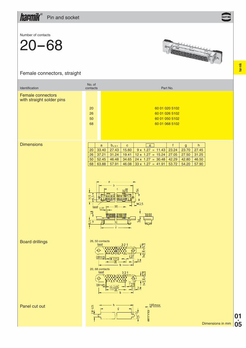
20 60 01 020 5102
26 60 01 026 5102
50 60 01 050 5102
68 60 01 068 5102
01.05
Pin and socket
Female connectors with straight solder pins
Dimensions
Panel cut out
Board drillings
No. ofIdentification contacts Part No.
Female connectors, straight
Number of contacts
20--68
Dimensions in mm
26, 50 contacts
20, 68 contacts
a b± 0.1 c e f g h 20 33.40 27.43 15.60 9 x 1.27 = 11.43 23.24 23.70 27.45 26 37.21 31.24 19.41 12 x 1.27 = 15.24 27.05 27.50 31.25 50 52.45 46.48 34.65 24 x 1.27 = 30.48 42.29 42.80 46.50 68 63.88 57.91 46.08 33 x 1.27 = 41.91 53.72 54.20 57.90
last
last
last
har·m
ik
01.06
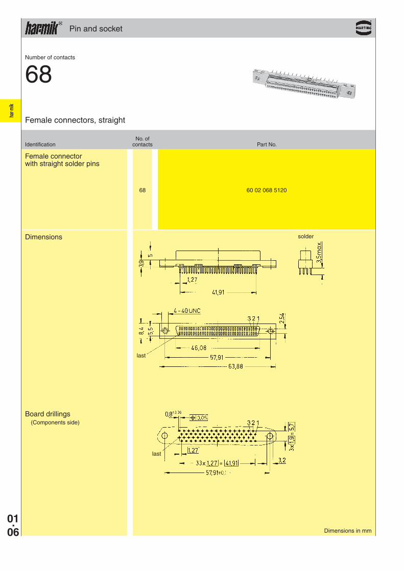
68 60 02 068 5120
Pin and socket
Female connector with straight solder pins
Board drillings(Components side)
Dimensions
No. ofIdentification contacts Part No.
Female connectors, straight
Number of contacts
68
Dimensions in mm
solder
last
last

har·m
ik
20 60 01 020 51 . .
26 60 01 026 51 . .
50 60 01 050 51 . .
68 60 01 068 51 . .
01.07
Pin and socket
Female connectors with angled solder pins
Panel cut out
Board drillings
Dimensions
No. ofIdentification contacts Part No.
Female connectors, angled
Number of contacts
20--68
Dimensions in mm
M 2.5 M 2.5 32M 2.5 Board lock 40
Panel fixing Board fixing
26, 50 contacts
20, 68 contacts
without board lock with board lock
a b± 0.1 c e f g h 20 33.40 27.40 15.60 9 x 1.27 = 11.43 23.24 23.70 27.45 26 37.21 31.24 19.41 12 x 1.27 = 15.24 27.05 27.50 31.25 50 52.45 46.45 34.65 24 x 1.27 = 30.48 42.29 42.80 46.50 68 63.88 57.88 46.08 33 x 1.27 = 41.91 53.72 54.20 57.90
last
last
last

har·m
ik
68 60 02 068 51 . . 100 60 02 100 51 . .
01.08
Pin and socket
Female connectors with angled solder pins
No. ofIdentification contacts Part No.
Female connectors, angled
Dimensions in mm
without screw lock with screw lock
without screw lock
with screw lock
Dimensions
Panel cut out
No. 1 contact
last
Number of contacts
68--100
a1 b e 68 54.22 57.91 33 x 1.27 = 41.91100 74.53 78.23 49 x 1.27 = 62.23
68 contacts, 100 contacts
With female screw lock 41Without female screw lock 50
Board drillings(Components side)
No. 1 contact without screw lock
with screw lock

har·m
ik
50 60 04 050 5343 60 04 050 5344
68 60 04 068 5343 60 04 068 5344
01.09
Pin and socket
Tooling see chapter 32 Cables see chapter 40
Female panel connectors with insulation displacement termination
for IDC flat cable pitch 0.635 mm AWG 30
Dimensions for connectorswith latch system
Panel cut out
Dimensions for connectorswith screw lock system
Panel cut out
with latch system with screw lock system
No. ofIdentification contacts Part No.
Female connectors for IDC flat cable, straight
Number of contacts
50--68
Dimensions in mm
a b c d1 d2 e f 50 52.45 46.48 34.70 42.80 42.30 30.48 42.30 68 63.88 57.91 46.13 54.23 53.72 41.91 53.72
last
last

har·m
ik
20 60 03 020 52 . .
26 60 03 026 52 . .
50 60 03 050 52 . .
68 60 03 068 52 . .
100 60 03 100 52 . .
01.10
Pin and socket
Hoods see pages 01.17, 01.18Tooling see chapter 32Cables see chapter 40
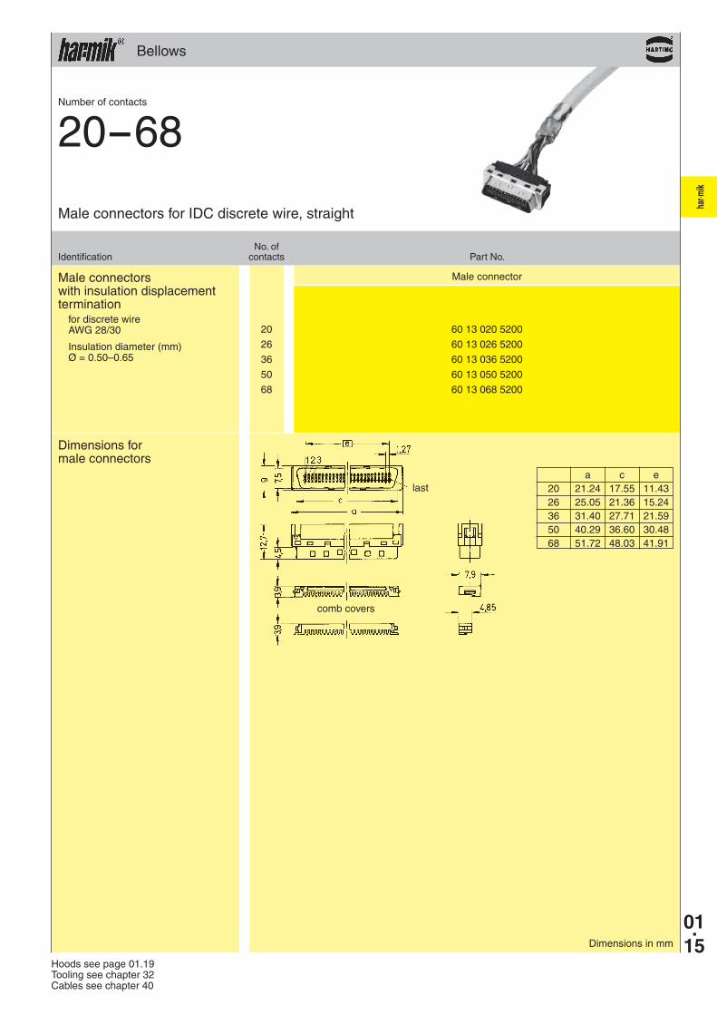
Male connectors with insulation displacement termination
for discrete wire AWG 28/30
Available sizes
No. ofIdentification contacts Part No.
Male connectors for IDC discrete wire, straight
Number of contacts
20--100
Comb cover(delivered with connectors)
Dimensions
Dimensions in mm
Ø = 0.50–0.65 00 Ø = 0.65–0.80 10 Ø = 0.80–0.88 20
Insulation diameter (mm)
= Available sizes
comb covers
last
Part No. Ø 20 26 50 68 100
60 03 . . . 5200 0.50–0.65
Male 60 03 . . . 5210 0.65–0.80
60 03 . . . 5220 0.80–0.88
a c d e 20 21.25 17.00 16.75 11.43 26 25.06 20.81 20.56 15.24 50 40.30 36.05 35.80 30.48 68 51.73 47.48 47.23 41.91 100 72.05 67.80 67.55 62.23

01.11
har·m
ik
Plating – state of the art engineering
High quality contact surfaces require expertise and latest technological equipment.
Technology at HARTING preserves natural resources thus improving the environ-ment

har·m
ik
01.12
Technical characteristicsBellows
Number of contacts 20, 26, 28, 36, 50, 68
Pitch 1.27 mm
Working current 1 A
Working voltage 240 V ~
Test voltage Ur.m.s. 750 V
Contact resistance ≤ 40 mΩ
Insulation resistance ≥ 103 MΩ
Temperature range -55 OC … + 105 OC
Terminations
Solder pins Straight for pcb holes min. Ø 0.74 mm Angled 90o for pcb holes min. Ø 0.74 mm
Insulation displacement AWG 28 to AWG 30 max. section: 0.089 mm² min. section: 0.050 mm² Insulation Ø min. 0.50 mm Ø max. 0.65 mm
Materials
Moulding Thermoplastic resin glass-fibre filled UL 94-V0
Contacts Copper alloy
Contact surface
Contact zone Selectively gold plated according to performance level
Metal shell Die cast zamac or stamped steel, nickel-plated
Bellowswith leaf contact design
male female

har·m
ik
26 60 11 026 5102
36 60 11 036 5202 60 11 036 5102
50 60 11 050 5202 60 11 050 5102
68 60 11 068 5102
01.13
Bellows
Male and female connectors with straight solder pins
Panel cut out
Dimensions for male connectors
Dimensions for female connectors
Board drillings
Male connector Female connector
No. ofIdentification contacts Part No.
Male and female connectors, straight
Number of contacts
26--68
Dimensions in mm
50 contacts
36 contacts
26, 50 contacts
36, 68 contacts
a b± 0.1 c e f g h 26 37.16 31.26 20.26 12 x 1.27 = 15.24 27.11 27.50 31.25 36 43.51 37.61 26.61 17 x 1.27 = 21.59 33.46 33.90 37.60 50 52.40 46.50 35.50 24 x 1.27 = 30.48 42.35 42.80 46.50 68 63.83 57.93 46.93 33 x 1.27 = 41.91 53.78 54.20 57.90
last
last
last
last
last
last

har·m
ik
20 60 11 020 51 . .
26 60 11 026 51 . .
28 60 11 028 5232
36 60 11 036 5232 60 11 036 51 . .
50 60 11 050 5232 60 11 050 51 . .
68 60 11 068 5232 60 11 068 51 . .
01.14 Dimensions in mm
28, 36, 68 contacts
50 contacts
Bellows
Male and female connectors with angled solder pins
Male connector Female connector
No. ofIdentification contacts Part No.
Male and female connectors, angled
Number of contacts
20--68
Without board lock 32With board lock 40
26, 50 contacts
20, 36, 68 contacts
without board lock with board lock
a b± 0.1 c e f g h 20 33.40 27.40 16.45 9 x 1.27 = 11.43 23.30 23.70 27.45 26 37.16 31.26 20.26 12 x 1.27 = 15.24 27.11 27.50 31.25 28 38.48 32.48 – 13 x 1.27 = 16.51 28.38 28.80 32.50 36 43.56 37.56 26.61 17 x 1.27 = 21.59 33.46 33.90 37.60 50 52.45 46.45 35.50 24 x 1.27 = 30.48 42.35 42.80 46.50 68 63.88 57.88 46.93 33 x 1.27 = 41.91 53.78 54.20 57.90
Panel cut out
Dimensions for male connectors
Board drillings
Dimensions for female connectors
last
last
last
last
last
last
har·m
ik
20 60 13 020 5200
26 60 13 026 5200
36 60 13 036 5200
50 60 13 050 5200
68 60 13 068 5200
01.15
Bellows
Hoods see page 01.19Tooling see chapter 32Cables see chapter 40
Male connectors with insulation displacement termination
for discrete wire AWG 28/30
Male connector
No. ofIdentification contacts Part No.
Male connectors for IDC discrete wire, straight
Number of contacts
20--68
Dimensions for male connectors
Dimensions in mm
Insulation diameter (mm)Ø = 0.50–0.65
comb covers
a c e 20 21.24 17.55 11.43 26 25.05 21.36 15.24 36 31.40 27.71 21.59 50 40.29 36.60 30.48 68 51.72 48.03 41.91
last

har·m
ik
01.16
Technical characteristicsHoods
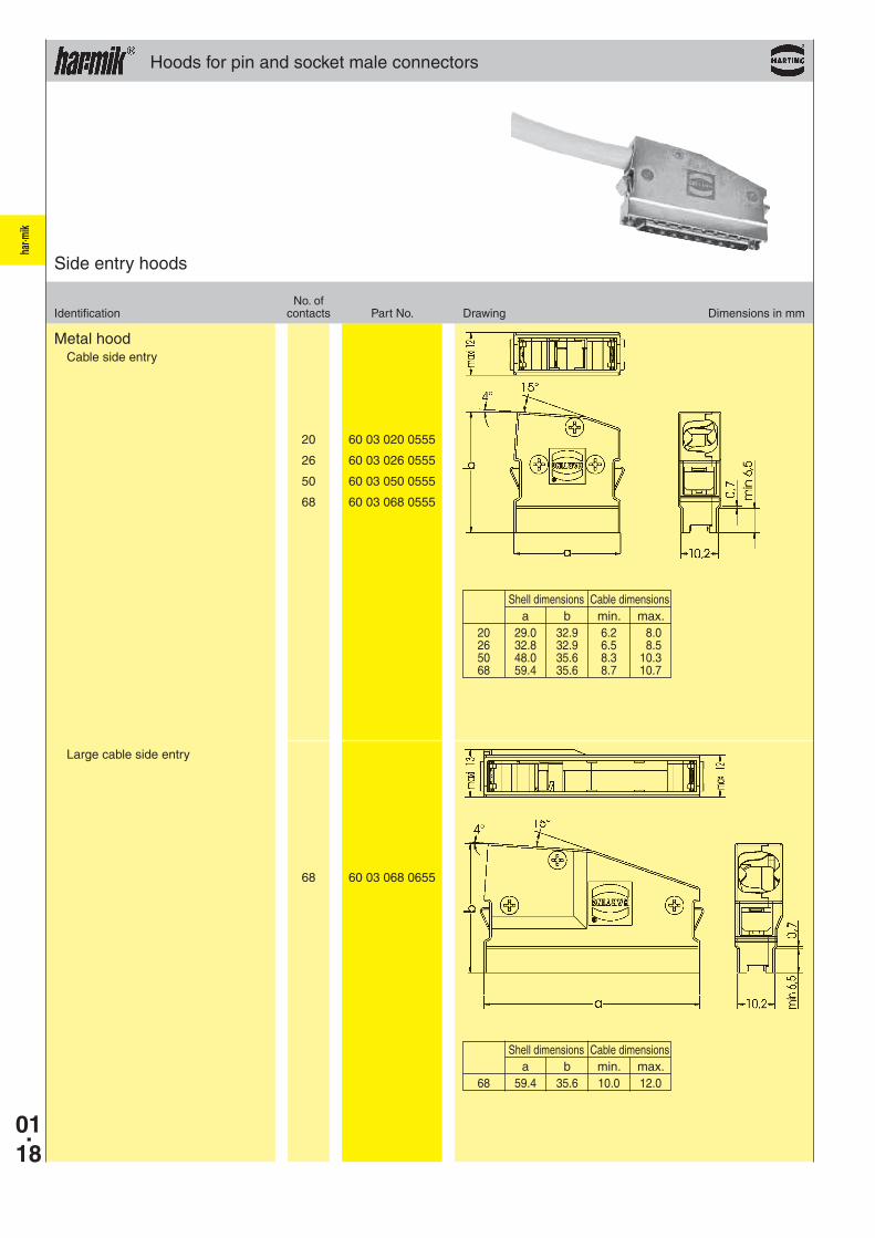
Hoods for pin and socket male connectors
Number of contacts 20, 26, 36, 50, 68, 100
Surface Die cast zamac, nickel-plated Thermoplastic resin, nickel-plated, steel insert
Hoods for bellows male connectors
Number of contacts 20, 26, 36, 50, 68
Surface Die cast zamac, nickel-plated Thermoplastic resin, nickel-plated, steel insert

har·m
ik
20 60 03 020 0255
26 60 03 026 0255
36 60 03 036 0255
50 60 03 050 0255
68 60 03 068 0255
01.17
50 60 03 050 0143
68 60 03 068 0143
100 60 03 100 0143
68 60 03 068 0145
Hoods for pin and socket male connectors
Metal hoodLarge cable entry
No. ofIdentification contacts Part No. Drawing Dimensions in mm
Top entry hoods
For other size, please consult us. 1) Temperature range: - 55 °C ... + 60 °C
a b c20 28.95 21.15 8.00 x 8.5026 32.76 24.96 8.00 x 6.7536 39.11 31.31 9.00 x 10.0050 48.00 40.20 9.00 x 10.0068 59.43 51.63 9.00 x 10.00
Metal hoodTop cable entry
Shell dimensions Cable dimensions a b min. max. 68 65.1 38.2 8.7 10.7
a b c d e 50 54.00 46.48 35.00 10.50 12.00 68 65.41 57.91 38.40 14.00 12.00 100 85.73 78.23 42.00 13.00 12.00
Plastic hood with internal screen1)
har·m
ik
20 60 03 020 0555
26 60 03 026 0555
50 60 03 050 0555
68 60 03 068 0555
68 60 03 068 0655
01.18
Hoods for pin and socket male connectors
Metal hoodCable side entry
No. ofIdentification contacts Part No. Drawing Dimensions in mm
Side entry hoods
Large cable side entry
Shell dimensions Cable dimensions a b min. max. 20 29.0 32.9 6.2 8.0 26 32.8 32.9 6.5 8.5 50 48.0 35.6 8.3 10.3 68 59.4 35.6 8.7 10.7
Shell dimensions Cable dimensions a b min. max. 68 59.4 35.6 10.0 12.0

har·m
ik
20 60 13 020 0153
26 60 13 026 0153
36 60 13 036 0153
50 60 13 050 0153
68 60 13 068 0153
01.19
26 60 13 026 0555
Hoods for bellows male connectors
No. ofIdentification contacts Part No. Drawing Dimensions in mm
Top or side entry hoods
Plastic hood with internal screen1)
a b c d 20 29.65 34.50 19.95 6.80 26 33.46 38.31 23.76 7.10 36 39.81 32.00 30.11 8.20 50 48.70 32.00 39.00 8.70 68 60.13 32.00 50.43 9.10
1) Temperature range: - 55 °C ... + 60 °C
Metal hoodCable side entry
Shell dimensions Cable dimensions a b min. max. 26 33.8 36.8 6.5 8.5

har·m
ik
60 01 000 9013
60 01 000 9018
60 01 000 9019
60 01 000 9020
60 01 000 9021
01.20
Accessories
Screw lockThread: M 2.5 / 2-56 UNCHeight: 2.9 mm
Screw lockThread: 4-40 UNC / 4-40 UNCHeight: 3.99 mm
Screw lockThread: 4-40 UNC / 2-56 UNCHeight: 3.99 mm
Screw lockThread: 4-40 UNC / 2-56 UNCHeight: 5.5 mm
Screw lockThread: 4-40 UNC / 4-40 UNCHeight: 5.5 mm
Identification Part No. Drawing Dimensions in mm
Female screw lock

har·m
ik
01.21
Certified according to EN ISO 9001in design/development, production,
installation and servicing
Intra cabinet connectors
for economical and reliable connections
A comprehensive range of high density intra cabinet connectors based on blade and fork contacts.
Available in a various number of contacts according to the following international standards and applications:
UL recognised
For customer specific applications we can design and manufacture solutions to match your requirement.
Sales department
HARTING components
Small Computer System Interface SCSI-2 SCSI-2 wide SCSI-3
Internal Bus extension through “Daisy chain” inter-linking via 0.635 mm pitch flat cable. The 4-point design of the IDC contact provides accurate and reliable termination even with teflon cable.

har·m
ik
01.22
Technical characteristics
Pitch 1.27 mm
Working current
pcb connector 1 A Flat cable connector 0.5 A
Working voltage
pcb connector 240 V ~ Flat cable connector 100 V ~
Test voltage Ur.m.s.
pcb connector 750 V Flat cable connector 500 V
Contact resistance ≤ 25 mΩ
Insulation resistance ≥ 103 MΩ
Temperature range -55 OC … + 105 OC
Terminations
Solder pins Straight for pcb holes min. Ø 0.74 mm
Insulation displacement Flat cable AWG 30 pitch 0.635 mm
Materials
Moulding Thermoplastic resin glass-fibre filled UL 94-V0
Contacts pcb connector Copper alloy Flat cable connector Nickel
Contact surface
Contact zone Selectively gold plated according to performance level
Pin and socket

har·m
ik
01.23
68 60 05 068 5100
solder
Pin and socket
Female connector with straight solder pins
Dimensions
Board drillings(Components side)
No. ofIdentification contacts Part No.
Female connectors, straight
Number of contacts
68
Dimensions in mm
last
last

har·m
ik
50 60 06 050 5440 60 06 050 9001 68 60 06 068 5440 60 06 068 9001
01.24
Pin and socket
Male connectors with insulation displacement termination
for IDC flat cable pitch 0.635 mm AWG 30 Strain relief order separately
Male connector Strain relief
No. ofIdentification contacts Part No.
Male connectors for IDC flat cable, straight
Number of contacts
50--68
Dimensions
Strain relief
Dimensions in mm
a 50 42.16 68 53.44
Tooling see chapter 32 Cables see chapter 40
a b c e 50 39.75 34.85 36.19 30.48 68 51.26 46.28 47.62 41.91
No. 1 contact