
Directivity of Speaker Arrays AN 70 - klippel.de · Directivity of Speaker Arrays AN 70 ... (e.g....
14
Directivity of Speaker Arrays AN 70 Application Note of the KLIPPEL R&D System (Document Revision 1.4) FEATURES SPL at any point in 3D space in near and far field Sound Power, Sensitivity, Directivity Index Polar Plot, Directivity Balloon, Contour Plot Automatic measurement of multiple transducers Superposition of multiple sound sources Simulation of beam steering and crossover settings APPLICATIONS Line Arrays Sound bars Beam steering Crossover design DESCRIPTION Using traditional far field measurement techniques, determining directivity of large speaker array implicates a lot of difficulties for the data acquisition. Far field conditions cannot be reached because of the limited size of the most anechoic rooms and the very directional radiation pattern requires a time consuming measure- ment with high angular resolution (<2°). The holographic measurement method of the Near Field Scanner can cope with these particularities, but the complex sound field (especially near field effects) requires a high number of expansion terms and a lot of measurement points. Decomposing the speaker into the individual transducers by measuring with a multi- plexer, the sound field of each source becomes relatively simple. Thus, the device can be described with a limited number of multipoles and a minimum number of measurement points. In addition, the acquired source data includes diffraction effects of the loudspeaker cabinet and is an ideal base for further simulation e.g. beam steering. Article number #2520-010, #2520-012, #2520-017, , #2800-102, #2800-104
-
Upload
phunghuong -
Category
Documents
-
view
233 -
download
1
Transcript of Directivity of Speaker Arrays AN 70 - klippel.de · Directivity of Speaker Arrays AN 70 ... (e.g....

Directivity of Speaker Arrays AN 70 Application Note of the KLIPPEL R&D System (Document Revision 1.4)
FEATURES
SPL at any point in 3D space in near and far field
Sound Power, Sensitivity, Directivity Index
Polar Plot, Directivity Balloon, Contour Plot
Automatic measurement of multiple transducers
Superposition of multiple sound sources
Simulation of beam steering and crossover settings
APPLICATIONS
Line Arrays
Sound bars
Beam steering
Crossover design
DESCRIPTION
Using traditional far field measurement techniques, determining directivity of large speaker array implicates a lot of difficulties for the data acquisition. Far field conditions cannot be reached because of the limited size of the most anechoic rooms and the very directional radiation pattern requires a time consuming measure-ment with high angular resolution (<2°).
The holographic measurement method of the Near Field Scanner can cope with these particularities, but the complex sound field (especially near field effects) requires a high number of expansion terms and a lot of measurement points. Decomposing the speaker into the individual transducers by measuring with a multi-plexer, the sound field of each source becomes relatively simple. Thus, the device can be described with a limited number of multipoles and a minimum number of measurement points.
In addition, the acquired source data includes diffraction effects of the loudspeaker cabinet and is an ideal base for further simulation e.g. beam steering.
Article number #2520-010, #2520-012, #2520-017, , #2800-102, #2800-104

Directivity of Speaker Arrays 1 Overview AN 70
KLIPPEL R&D System Page 2 of 14
CONTENT
1 Overview ........................................................................................................................................................ 3
2 Requirements ................................................................................................................................................. 5
3 Performing a measurement ........................................................................................................................... 6
4 Data Processing ............................................................................................................................................ 10
5 References .................................................................................................................................................... 12
6 Trouble Shooting .......................................................................................................................................... 13

Directivity of Speaker Arrays 1 Overview AN 70
KLIPPEL R&D System Page 3 of 14
1 Overview
1.1 Principle
The measurement is based on an elementary characteristic of sound waves, su-perposition. That means the complex sound pressure field of two individual sources (p1 and p2) can be summed to a resultant sound pressure field ptotal.
𝑝𝑡𝑜𝑡𝑎𝑙 = 𝑝1 + 𝑝2
This application note shows how sound wave superposition can be combined with a holographic measurement system (NFS) to determine more accurate, versatile and comprehensive measurement data of large audio de-vices (e.g. Line Arrays, sound bars, etc.)
Step 1: Automatic measurement
At first a near field scan is performed. Using a multiplexer, each transducer is measured separately in only 1 scan. During the measurement the device under test is not moved to avoid positioning mismatches and deter-mining accurate phase data for each transducer.
Step 2: Holographic Field Identification of each source After the measurement, the sound field of each transducer is identified by the spherical wave expansion. Be-cause of the separate measurements, the individual sources are relatively simple and the sound field can be modelled with a relative low number of expansion terms, saving measurement points and time. Step 3: Superposition of sound sources
In the last processing step, the individual sources are superimposed in the visualization software to extrapolate the entire sound pressure output at any position in 3D space. In addition, adding a time delay or complex filter to each sound source the beam steering can be directly simulated based on the measured source data.
Multiplexer
1. Scanning each transducer output
3. Superposition of all sound sources
+
+
+
...
2. Separate wave expansions

Directivity of Speaker Arrays 1 Overview AN 70
KLIPPEL R&D System Page 4 of 14
1.2 Measurement Results
SOUND PRESSURE LEVEL
35
40
45
50
55
60
65
70
75
80
85
On Axis
30° Off Axis
60° Off Axis
100 1k 10kf in Hz
dB
SP
L
Sound Pressure Level over frequency at any position in 3D space.
SOUND POWER
60
65
70
75
80
85
90
95
100
105
110
100 1k 10k
f in Hz
dB
So
un
d P
ow
er
Total radiated Sound Power of the device under test.
Sound power characterizes the inte-grated sound pressure level over all radi-ation angles.
DIRECTIVITY INDEX
0
2
4
6
8
10
12
14
10 2 10 3 10 4
f in Hz
dB
Dire
ctivity In
de
x
The Directivity Index summarizes the re-lation between the sound pressure levels of all radiation angles compared to the On-Axis sound pressure level.
An omnidirectional source has a directiv-ity index of 0.
SENSITIVITY
35
40
45
50
55
60
65
70
75
80
85
100 1k 10kf in Hz
dB
SP
L
On-Axis sound pressure level referenced to 1m distance and 1W electrical input power (2.83V for 8Ω)
CONTOUR PLOT
The contour plot visualizes the radiation behavior over frequency and the polar angle theta. The color scale indicates the Sound Pressure Level.
POLAR PLOT
Polar plots visualize the radiation pattern over the polar angle theta for a specific frequency.
Directivity of Speaker Arrays 2 Requirements AN 70
KLIPPEL R&D System Page 5 of 14
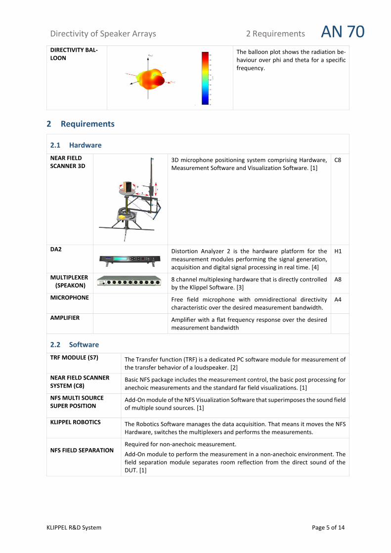
DIRECTIVITY BAL-LOON
The balloon plot shows the radiation be-haviour over phi and theta for a specific frequency.
2 Requirements
2.1 Hardware
NEAR FIELD SCANNER 3D
3D microphone positioning system comprising Hardware, Measurement Software and Visualization Software. [1]
C8
DA2
Distortion Analyzer 2 is the hardware platform for the measurement modules performing the signal generation, acquisition and digital signal processing in real time. [4]
H1
MULTIPLEXER (SPEAKON)
8 channel multiplexing hardware that is directly controlled by the Klippel Software. [3]
A8
MICROPHONE Free field microphone with omnidirectional directivity characteristic over the desired measurement bandwidth.
A4
AMPLIFIER Amplifier with a flat frequency response over the desired measurement bandwidth
2.2 Software
TRF MODULE (S7) The Transfer function (TRF) is a dedicated PC software module for measurement of the transfer behavior of a loudspeaker. [2]
NEAR FIELD SCANNER SYSTEM (C8)
Basic NFS package includes the measurement control, the basic post processing for anechoic measurements and the standard far field visualizations. [1]
NFS MULTI SOURCE SUPER POSITION
Add-On module of the NFS Visualization Software that superimposes the sound field of multiple sound sources. [1]
KLIPPEL ROBOTICS The Robotics Software manages the data acquisition. That means it moves the NFS Hardware, switches the multiplexers and performs the measurements.
NFS FIELD SEPARATION
Required for non-anechoic measurement.
Add-On module to perform the measurement in a non-anechoic environment. The field separation module separates room reflection from the direct sound of the DUT. [1]
Directivity of Speaker Arrays 3 Performing a measurement AN 70
KLIPPEL R&D System Page 6 of 14
3 Performing a measurement
3.1 Introduction
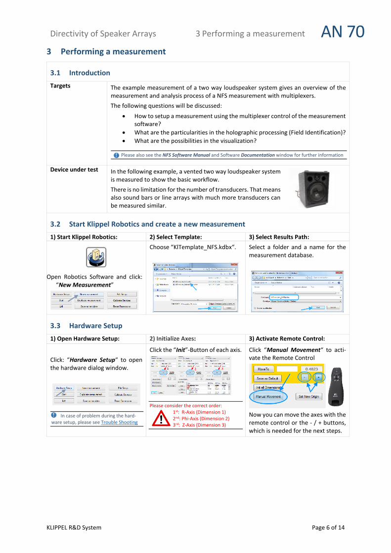
Targets The example measurement of a two way loudspeaker system gives an overview of the measurement and analysis process of a NFS measurement with multiplexers.
The following questions will be discussed:
How to setup a measurement using the multiplexer control of the measurement software?
What are the particularities in the holographic processing (Field Identification)?
What are the possibilities in the visualization?
Please also see the NFS Software Manual and Software Documentation window for further information
Device under test In the following example, a vented two way loudspeaker system is measured to show the basic workflow.
There is no limitation for the number of transducers. That means also sound bars or line arrays with much more transducers can be measured similar.
3.2 Start Klippel Robotics and create a new measurement
1) Start Klippel Robotics: 2) Select Template: 3) Select Results Path:
Open Robotics Software and click: “New Measurement”
Choose “KlTemplate_NFS.kdbx“.
Select a folder and a name for the measurement database.
3.3 Hardware Setup
1) Open Hardware Setup: 2) Initialize Axes: 3) Activate Remote Control:
Click: “Hardware Setup“ to open the hardware dialog window.
In case of problem during the hard-ware setup, please see Trouble Shooting
Click the “Init”-Button of each axis.
Please consider the correct order: 1st: R-Axis (Dimension 1) 2nd: Phi-Axis (Dimension 2) 3rd: Z-Axis (Dimension 3)
Click “Manual Movement“ to acti-vate the Remote Control
Now you can move the axes with the remote control or the - / + buttons, which is needed for the next steps.
Directivity of Speaker Arrays 3 Performing a measurement AN 70
KLIPPEL R&D System Page 7 of 14
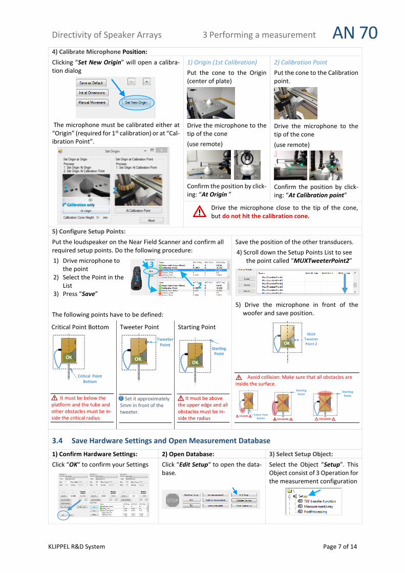
4) Calibrate Microphone Position:
Clicking “Set New Origin” will open a calibra-tion dialog
The microphone must be calibrated either at “Origin” (required for 1st calibration) or at “Cal-ibration Point”.
1) Origin (1st Calibration)
Put the cone to the Origin (center of plate)
Drive the microphone to the tip of the cone
(use remote)
Confirm the position by click-ing: “At Origin ”
2) Calibration Point
Put the cone to the Calibration point.
Drive the microphone to the tip of the cone
(use remote)
Confirm the position by click-ing: “At Calibration point”
Drive the microphone close to the tip of the cone, but do not hit the calibration cone.
5) Configure Setup Points:
Put the loudspeaker on the Near Field Scanner and confirm all required setup points. Do the following procedure:
1) Drive microphone to the point
2) Select the Point in the List
3) Press “Save”
The following points have to be defined:
Critical Point Bottom
Critical Point Bottom
OK
It must be below the platform and the tube and other obstacles must be in-side the critical radius
Tweeter Point
Tweeter Point
OK
Set it approximately 5mm in front of the tweeter.
Starting Point
OK
Starting Point
It must be above the upper edge and all obstacles must be in-side the radius
Save the position of the other transducers.
4) Scroll down the Setup Points List to see the point called “MUXTweeterPoint2”
5) Drive the microphone in front of the woofer and save position.
Avoid collision: Make sure that all obstacles are inside the surface.
Critical Point Bottom
COLLISION
Starting Point
COLLISION
Starting Point
COLLISION
3.4 Save Hardware Settings and Open Measurement Database
1) Confirm Hardware Settings: 2) Open Database: 3) Select Setup Object:
Click “OK“ to confirm your Settings
Click “Edit Setup“ to open the data-base.
Select the Object “Setup”. This Object consist of 3 Operation for the measurement configuration
1st Calibration only
2
3
1

Directivity of Speaker Arrays 3 Performing a measurement AN 70
KLIPPEL R&D System Page 8 of 14
3.5 Measurement operation – TRF transfer function
1) Connect Hardware
2) Select operation 3) Property Page
Select the operation:
“TRF transfer function ”
Open “Property Page” to configure the measurement operation.
4) Configure Stimulus 5) Define Channels and H(f)
Select the “Stimulus“ tab and define:
“Speaker 1 (via OUT1)“
Configure Parameters:
Frequency Range (fmin , fmax)
Frequency Resolution
Input Voltage
1) Select the “Input“ tab and define:
Channel 1 – (Voltage Speaker 1) Us
Channel 2 - IN 2 (Mic)
2) Insert the calibration factor of the mic
3) Select the “Processing „Tab and define: H(f)= IN2 / Us
MUX CH1 → Tweeter
MUX CH2→ Woofer
DA SP1 → BUS A
MIC → IN2
OUT1 → AMP
Distortion Analyzer Multiplexer
1
2

Directivity of Speaker Arrays 3 Performing a measurement AN 70
KLIPPEL R&D System Page 9 of 14
6) Switch Multiplexer and Run Operation 7) Check SNR
1) Click the manual switch button of the MUX. 2) And route “BUS A” to “CH 1” to connect the Tweeter.
If the routing with the manual switch is not possible please see the multiplexer manual [7]
Run the TRF operation by clicking on the green arrow.
The measurement should be performed in front of the loud-speaker. Move the microphone to the On-Axis position.
Open the Result Windows “Y1(f) Spectrum” and “Y2(f) Spectrum”. Check if the microphone signal has a Signal to Noise Ratio (SNR) of at least 40dB in the passband.
If the SNR is less increase the voltage of the Stimulus or apply averaging.
Repeat the same check for the Woofer.
(“BUS A” to “CH2”)
3.6 Measurement Array
1) Select Operation 2) Grid Configuration
Select the operation:
“MeasurementArray ”
and open the Property Page.
Open the “Input” tab to configure the Parameter, listed under “Grid Configuration”. Please define:
Number of Points
Use Field Separation
Reflection Free Distance
Frequency Resolution
See the “Documentation” window, for information about the parameters.
3) Measurement Operation and Multiplexer settings
Step 1: Reset Configuration
1) Open the Category Measurement Operation 2) Click Delete all Operations to reset the Opera-
tion List
Step 2: Select Measurement Module
1) Select “New Operation” in the Operation List 2) Click Update Measurement Modules to refresh,
the list of Measurement Modules 3) Select the Module for the measurement e.g.
“TRF transfer function”
Step 3: Configure Multiplexer Settings
1) To add a switching configuration of a MUX click Use Multiplexer
2) Select in the list the MUX that should be switched or Update List to see all MUXes
3) Click MUX-Activate to activate the multiplexer. 4) Adjust the switching configuration.
For the Tweeter set: Mode: 1x8 ,Ch.: 1 to A/B 5) Click Switch Configuration to switch the MUX and
check your configuration
2 1
1) 2)
3)
1) 2)
3)
5)
4)
1) 2)

Directivity of Speaker Arrays 4 Data Processing AN 70
KLIPPEL R&D System Page 10 of 14
Step 4: Transducer Name + Save Configuration
1) To save the results in a separate data container, set the parameter Transducer Position/Name: E.g. “Tweeter”
2) Click Save in Operation List to store the current Setup
Setup for Woofer
Repeat step 2-4 for the Woofer
Use the following Settings:
MUX – Mode: 1x8
MUX – Channel: 2 > A/B
Transducer Position/Name: Woofer
4) Run Operation
Run the Measurement Array operation by clicking on the green arrow.
After running the Script the measurement points and the multiplexer settings are shown in a table in the Result window Table of Coordinates.
3.7 Start Measurement
Close database to get back to the Robotics and Press “Start”
Press “Continue” to Start the measurement. In the following, the Robotics Software will control the automatic measurement.
4 Data Processing
4.1 Result Database
1) Open Database 2) Database Structure
After the measurement has finished, click Show Result dB to open the Database
Open the Object Processing
After the measurement this Object should contain 2 Data Containers with names of the defined Transducer names. (e.g. “Tweeter” and “Woofer”)
4.2 Measurement Data Containers
1) Select Data Container (Tweeter) 2) Configure Delay Settings
Select Operation: 1 Measurement Data Container (Tweeter)
Open the Property Page
1) Activate the Flag Edit Parameters 2) Apply Minimum Delay = 0
Avoid phase mismatches - Use same delay for all transducers!
2)
1) 2)
1)

Directivity of Speaker Arrays 4 Data Processing AN 70
KLIPPEL R&D System Page 11 of 14
1)
2)
3) Set Tweeter Point and Reference Point 4) Configure Data Container (Woofer)
1) Select from the List of saved Tweeter Points the po-sition that is in front of the tweeter. (e.g. Tweeter Point 1)
2) Set the Reference Point to same position, by copy-ing the coordinates.
3) Run the operation
Repeat 1), 2) and 3) for the Measurement Data Con-tainer of the Woofer
1) Apply same delay 2) Select Tweeter
Point 3) Set Reference
Point 4) Run Operation
4.3 Field Identification
1) Duplicate and rename Field Identification 2) Select Data Containers and Run Operations
1) Right click the Operation “2 Field Identification” and select Duplicate
2) Give both Field Identifications a clear name e.g. use the transducer names “Tweeter” and “Woofer”
Open Property Page of the Field Identification module and make sure the correct Data Container is selected (e.g. Tweeter )
When the configuration is fine, Run module
4.4 Visualization
1) Select Visualization Select Operation: 3 Visualization
Open the Property Page
2) Activate Multiple Source Mode 3) Configure Number of Source
Add-On Module required: NFS Multi Source Superposition
Open the Category “Multi Source – Global settings” and define the number of sources. For this example 2
4) Configure Multi Source - Source Settings Configuration of Tweeter:
1) Select Source 1 2) Choose source data:
2 Field Identification (Tweeter)
3) Click Import Parameter to load Reference Point
Configuration of Woofer: 1) Select Source 2 2) Choose source data:
2 Field Identification (Woofer)
3) Click Import Parameter to load Reference Point
1)
2)
2)
1) 3) 3)
2) 1)
1)
2)
3)

Directivity of Speaker Arrays 5 References AN 70
KLIPPEL R&D System Page 12 of 14
5) Global Reference Point 6) Run Visualization
Define a Global Reference Point. E.g. Set to the Position of the Woofer
Click the green arrow to run the operation. This will show a user interface and the data can be analyzed.
7) Cabinet and transducer Diameter (optional) For a better understanding of the multisource configuration, cabinet information can be added. Define the coordinates of loudspeaker edges either in the NFS coordinate system (x,y,z origin at center of the NFS) or relative to the Reference system (rref≜origin, nref≜ z-axis, oref ≜ x-axis) For example define for the Woofer the following cabinet information: (Coordinates are Related to Reference coordinates Sys-tem)
0.2 0.1 0 //Front-Right-Up
0.2 -0.1 0 //Front-Left -Up
-0.1 0.1 0 //Front-Right-Bottom
-0.1 -0.1 0 //Front-Left -Bottom
0.2 0.1 -0.18 //Back -Right-Up
0.2 -0.1 -0.18 //Back -Left -Up
-0.1 0.1 -0.18 //Back -Right-Bottom
-0.1 -0.1 -0.18 //Back -Left -Bottom
Also define the diameter of the transducers:
e.g. Woofer 18cm / Tweeter 5cm
Click Plot Multi Source Configuration
This will show up a graphic window that visualizes the current configuration
5 References
5.1 Related Modules
[1] Near Field Scanner 3D (NFS), Specification C8, 2016 Klippel GmbH, www.klippel.de
[2] Transfer function (TRF), Specification S7, 2016 Klippel GmbH, www.klippel.de
[3] Multiplexer, Specification A8, 2016 Klippel GmbH, www.klippel.de
[4] Distortion Analyzer 2, Specification H1, 2016 Klippel GmbH, www.klippel.de
5.2 Manuals [5] User Manual Near Field Scanner 3D (NFS), included in NFS Software installation
[6] User Manual TRF Transfer function, included in dB-Lab Software installation
[7] User Manual MUX, included in dB-Lab Software installation
5.3 Publications [8] W. Klippel, C. Bellmann: Holographic Nearfield Measurement of Loudspeaker Di-
rectivity, AES 2016 - 141th Convention, Audio Engineering Society
[9] C. Bellmann, W. Klippel, D. Knobloch: Holographic loudspeaker measurement based
on near field scanning, DAGA 2015 - 41th Convention, DEGA e.V.
5.4 Standards [10] IEC (E) 60268-21: Acoustical (Output based) Measurements, 2015 International Elec-
trotechnical Commission
[11] IEC 62777 Ed.1: Quality Evaluation Method for the Sound Field of Directional Loud-
speaker Array System, 2014 International Electrotechnical Commission
[12] CEA-2034: Standard Method of Measurement for In-Home Loudspeakers, 2013 Con-
sumer Electronics Association
Directivity of Speaker Arrays 6 Trouble Shooting AN 70
KLIPPEL R&D System Page 13 of 14
6 Trouble Shooting
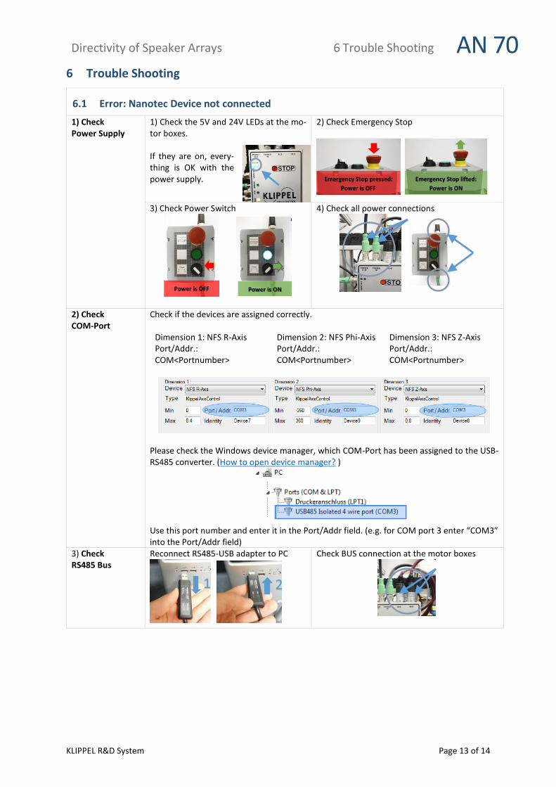
6.1 Error: Nanotec Device not connected
1) Check Power Supply
1) Check the 5V and 24V LEDs at the mo-tor boxes. If they are on, every-thing is OK with the power supply.
2) Check Emergency Stop
3) Check Power Switch
4) Check all power connections
2) Check COM-Port
Check if the devices are assigned correctly.
Dimension 1: NFS R-Axis Port/Addr.: COM<Portnumber>
Dimension 2: NFS Phi-Axis Port/Addr.: COM<Portnumber>
Dimension 3: NFS Z-Axis Port/Addr.: COM<Portnumber>
Please check the Windows device manager, which COM-Port has been assigned to the USB-RS485 converter. (How to open device manager? ) Use this port number and enter it in the Port/Addr field. (e.g. for COM port 3 enter “COM3” into the Port/Addr field)
3) Check RS485 Bus
Reconnect RS485-USB adapter to PC
Check BUS connection at the motor boxes
Emergency Stop lifted:
Power is ON
Emergency Stop pressed:
Power is OFF
Power is ON Power is OFF
2 1
Directivity of Speaker Arrays 6 Trouble Shooting AN 70
KLIPPEL R&D System Page 14 of 14
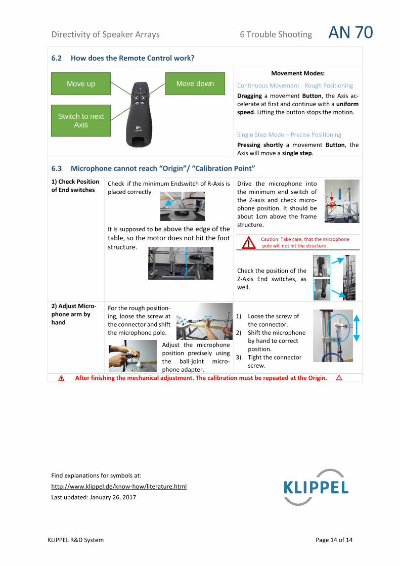
6.2 How does the Remote Control work?
Movement Modes:
Continuous Movement - Rough Positioning
Dragging a movement Button, the Axis ac-celerate at first and continue with a uniform speed. Lifting the button stops the motion.
Single Step Mode – Precise Positioning
Pressing shortly a movement Button, the Axis will move a single step.
6.3 Microphone cannot reach “Origin”/ “Calibration Point”
1) Check Position of End switches
Check if the minimum Endswitch of R-Axis is placed correctly
It is supposed to be above the edge of the table, so the motor does not hit the foot structure.
Drive the microphone into the minimum end switch of the Z-axis and check micro-phone position. It should be about 1cm above the frame structure.
Caution: Take care, that the microphone pole will not hit the structure.
Check the position of the Z-Axis End switches, as well.
2) Adjust Micro-phone arm by hand
For the rough position-ing, loose the screw at the connector and shift the microphone pole.
Adjust the microphone position precisely using the ball-joint micro-phone adapter.
1) Loose the screw of
the connector. 2) Shift the microphone
by hand to correct position.
3) Tight the connector screw.
After finishing the mechanical adjustment. The calibration must be repeated at the Origin.
Find explanations for symbols at:
http://www.klippel.de/know-how/literature.html
Last updated: January 26, 2017
Move down
Switch to next Axis
Move up
1cm


![Fling StepForward Directivity (BRBF)confnews.um.ac.ir/images/41/conferences/5ncce/1399.pdf · Fling StepForward Directivity Forward Directivity . [] g Forward Directivity Fling Step[]](https://static.fdocuments.net/doc/165x107/5ead3a2bf150643e9064f1eb/fling-stepforward-directivity-brbf-fling-stepforward-directivity-forward-directivity.jpg)