phase & residual overcurrent, phase & Ground directional ...

Westinghouse 1. L. 41-131M
INSTALLATION • OPERATION • MAINTENANCE
INSTRUCTIONS DIRECTIONAL OVERCURRENT RELAYS
TYPES: CR, CRC, CRP AND CRD
C A U T I O N Be fore p utting re lays into service , remove all bloc king which may have been inse rted for the p urp ose of sec uring the parts during shipment, make sure that all moving parts ope rate freely, inspect the c ontacts to see that the y a re c lean and c lose p rope rly, and operate the relay to chec k the s E!ttings and e lec trical c onnections.
AP PL ICATION
These induction type directional ove rc urrent relays are use d to disc onnect transmission and feeder circuits when c urrent through them in a given direc tion excee ds a p redete rmined value.
CONTENTS
This instruction leaflet applies to the following types of relays:
T ype CR Voltage P olarize d Phase Relay T ype CRC Current Polarize d Groun d Relay T ype CRP Voltage P olarized G round Rela y T ype CRD D ual Polarized G round Relay
CONST RUCTION AND O P E RATION
The various types of relays as outline d in the contents consist of a directional unit or units , an ove rc urrent unit, an indicating c ontactor switch unit and an indicating instantaneous trip unit when re quired. The type CRP and type CRD re lays a ls o utilize an internal p hase shifting mechanism. The p rincipal c omponent parts of the relay and their locations are shown in Figs. 1, 2, 3 and 4.
A. Ove rc urrent Unit (CO)
The ove rc urrent unit operates on the in duction p rinciple. A main tapped c oil locate d on the cente r leg of an "E" type laminate d structure produces a flux which divides and returns th rough the outer legs. A shading coil causes the flux through the le ft leg to lag the main p ole flux. The out-of-phase fluxes thus p roduced in the air gap cause a c ontac t c losing torque .
B. Indicating Contactor Switch Unit (ICS)
The indicating c ontactor switch is a small d-e operate d c lapper type device. A magnetic armature , to which leaf-spring mounted c ontacts are attache d, is att racted to the magnetic c ore up on ene rgizati on of the switch . When the switch c loses , the m oving
SUPERSEDES I.L. 41-131L *Denotes cha nge from supe rseded 1ssue .
c ontacts bridge two stationary c ontacts, c omp leting the trip circ uit. Als o during this ope ration two finge rs on the armature de flect a spring loc ated on the front of the switch, which a llows the ope ration indicator target to drop . The target is reset from the outside of the case by a p ush rod located at the bottom of the cover.
The front spring , in addition to h olding the target, provides restraint for the armature and thus c ontrols the pickup value of the switch .
C . Indicating Instantaneous Trip Unit (liT)
The instantane ous trip unit is a small a-c ope rate d c lapper type device . A magnetic armature , to which leaf-spring mounted c ontacts a re attached, is attracte d to the magnetic c ore upon ene rgization of the switch. When the switch c loses , the m oving c ontacts bridge two stationary c ontacts c omp leting the trip circuit. Also during the operation two fingers on the armature de flect a spring located on the front of the switch which allows the operation indicator t arget to drop. The target is reset from the outside of the case by a p ush rod loc ated at the bottom of the c over.
A c ore screw accessible from the top of the switch p rovi des the a djustable pickup range.
D. Directional Unit ( D )
The directional unit i s a p roduct induction c ylinde r type unit operating on the inte raction between the p olarizing circ uit flux and the operating circ uit flux.
Mechanically, the directional unit is c omp osed of four basic components: a die-cast aluminum frame an e lect romagnet, a moving e lement assem bly, and � molded bridge.
The frame serves as the m ounting structure for the magnetic c ore . The magnetic c ore which h ouses the lower pin be aring is secure d to the frame by a locking nut. The bearing can be rep lace d, if necessary, with out having to rem ove the magnetic c ore from the frame.
The e lect romagnet has two series-c onnecte d p olarizing c oils m ounte d diametrically opp osite one anothe r; two series-c onnected ope rating c oils m ounte d diametrically opp osite one anothe r; tw o magnetic adj usting p lugs ; upper and lowe r a djusting p lug c lips , and two locating pins . The locating pins are use d to acc urately position the lower pin be aring, which is m ounte d on the frame , with respect to the
EFFECTIVE FEBRUARY 1973 www . El
ectric
alPar
tMan
uals
. com

N
\ I
Fig. 1 Type CR Relay Without Case. (D). 2-0vercurrent Unit (CO),
factor Switch (ICS).
1-Directional Unit 3-lndicating Con-
Fig. 2. Directional Unit. 1-Stationary Contact. 2·
Stationary Contact pressure spring. 3-Magnetic
adjusting plugs. 4-Upper bearing screw. 5-Moving elem�nt assembly. 6-Spring adjuster
clamp. 7-Current Bias Vane.
� -< "'tl m V' (") :::0 (") :::0 n (") :::0 "'tl >-z 0 (") :::0 0 :::0 m r >--< V'
www . El
ectric
alPar
tMan
uals
. com

TYPES CR ,CRC, CRP AND CRD REL AYS _______ _ I.L. 41-131M
Fig. 3. Time Overcurrent Unit (Front View). 1- Tap Block. 2- Time Dial. 3-Control Spring Assembly. 4-Disc. 5-Stationary
Contact Assembly. 6-Magnetic Plugs. 7-Permanent Magnet.
Fig. 4. Indicating Instantaneous Trip Unit (liT).
3 www . El
ectric
alPar
tMan
uals
. com

TYP ES CR, C RC , CRP AND CRD R EL AYS _____________________ _
DIIECTIOIIIALUJIIT
IIIDICATIIG COM-TACTOR SWITCH-
WITH IEUTIYE IIIISTAIITAIIEOUS I'OlAIIITY AS SHOMI THE DIIECTIOifAI. !Mill CC*TACTS CLOSE
INTERNAL SCHEM.ATIC
IIIDUCTIOMIIIIT
REDHAIIOLE
TERMtUL
57-D-4')47
Fig. 5. Internal Schematic of double trip, directional overcurrent relay type CR in type FT21 Case. For the single trip relay the circuits associated with terminal 2 are omitted, 5704549.
uppe r pin be aring, which is th re ade d into the bridge. The e lectromagnet is secure d to the frame by four m ounting screws.
The m oving e lement assembly c onsisl,s of a s piral s pring, c ontact c arrying membe r, an d an aluminum c ylin de r assembled to a m olde d h ub which holds the shaft. The shaft has removable top and bottom jewel bearings. The sh aft rides between the bott om pin bearing and the uppe r pin bearing with the c ylin de r rotating in an air gap forme d by the e lectromagnet and the magnetic c ore. The st ops for the m oving e le ment c ontact arm are an integral part of the bridge.
The bridge is sec ured to the e lectrom agnet an d frame by two m ounting sc rews. In addition to holding the uppe r pin be aring, the bridge is use d for mounting the adjustable stationary c ontact housing. The stationary c ont act h ousing is he ld in . position by a s pring t ype c lamp. The s pring adjuste r is loc ate d on the underside of the bridge an d is attache d to the m oving c ontact arm by a s piral s pring. The s pring adjuster is also he ld in place by a spring type c lamp.
With the c ontacts c lose d, the e lectric al c on nection i s made th rougl"1 the st ationary c ontact h ousing c lamp, to the moving c ontact, th rough the s piral spring out to the s pring adjuste r c lamp.
The c ont acts of the directi or!al unit are c onnected in s e ries with the shading c oil of the ove rcurrent unit , thus giving directional c ontrol of the ove rc urrent unit. This arrangement prevents the relay from ope rating for faults in the non-t ripping direction.
4
DIIUTIIUI. HIT"'
IUICATIRQ CIIITACTDI WI TCtl ---
Wlltl UU.TIVE IISTAIHUEOU NlAIITY AS SltOWI THE DIRECTUIIAI. UIIT COITACTS ClOSE
UHEIUL SCHEMAtiC
57-D-4543
Fig. 6. Internal Schematic of double trip, directional overcurrent relay type CRC in type FT21 Case. For the single trip relay the circuits associated with terminal 2 are omitted, 5704539.
CHARACT ERISTICS
The time characte ristics of the directi onal ove rcurrent relays are designated by s pecific numbers as indic ated in Table I (e .g. CR-8).
TABLE I
Time
Characteristics
Short Time
Long Time
Definite Time Moderately Inverse Time
Inverse Time
Very Inverse Time
Extremely Inverse Time
Designation
2
5 6
7
8 9
11
The re lays are gene rally available in the follow ing ove rc urrent unit c urrent ranges:
Range
0.5- 2.5 2 - 6 4 - 12
Taps
0.5 0.6 0.8 1.0 1.5 2 2.5 3 3.5 4 4 5 6 7 8
2.0 5
10
2.5 6
12
The s e relays may have either single or double c ircuit c losing c ontacts for tri pping eith e r one or two c ircuit breake rs.
The time vs. current characte ristics are shown in Figs. 13 to 19. These characte ri stics give the c ontact closing time for the vari ous time dial settings when the indic ated m ultipl�s of tap value current are applied to the re lay.
www . El
ectric
alPar
tMan
uals
. com

TYP ES CR, CRC, CRP AND CRD R EL AYS _______________ ___ _ I.L. 41·131M
INTERNAL iCHEMUIIC
tiiEcn•AL "I UIIT -,
WITif IEU.TU£ I.JTAITAIEMS Nt.AIITY AI ... TIE tiiECTI•M. IIIIT COIT..CT1 CUIE
fROtH �lEW
57-D-4541
Fig. 7. Internal Schematic of double trip, directional overcurrent relay type CRP in type FT21 Case. For the single trip relay the circuits associated with terminal 2 are omitted, 5704545.
Trip Circuit
The main contacts w ill safely c lose 30 amperes at 250 volts d-e and the seal-in contacts of the indicating contactor switch wi ll safe ly carry this current long enough to trip a circuit breaker.
The indicating instantaneous trip c o ntacts wi ll safely c lose 30 amperes at 250 volts d-e, and wi ll c arry this current long enough to trip a breaker.
The indicating contactor switch has two taps that provide a pickup setting of 0 .2 or 2 amperes . To change taps re quires connecting of lead located in front o f the tap b lock to the desired setting by means of a screw connection.
Trip Circuit Constants
Indicating Contactor Switch -0 . 2 amp tap 6.5 ohms d-e resistance 2.0 amp tap 0 . 1 5 ohms d- e resistance
Type CR Relay
This vo ltage po larized typ e relay is i nten ded for phase fau lt protection an d the directional unit has its maximum torque whe n the current leads the vo ltage by approximately 30 ° . The directional uni t minimum pickup is 1 vo lt and 4 amp eres at its maximum torqu e angle for the 4 to 12 amp ere range relays an d 1 vo lt and 2 amp eres for the 2 to 6 ampere and 0 . 5 to 2 . 5 amp ere range relays.
The directional unit sho u ld be connected u sing the current in o ne-phase wire an d the pote ntial acro ss the other two phase wires. This co nnectio n is com monly
( -�-��EIUULSCHEMA!IC
I , I INDICATING - -���;.,.J COMTACTORSWITCH j ,_1
l'r� !c�rfn t' tJ I I
WITHII:ELATI¥E I IMSTAIIfAMEOUS POLARITY AS SHOWN I TilE Otil:ECTIOfiAl UIIIT; I A CONTACTS CLOSE 1l1-(�
�' FRONT ¥lEW
UPPER DIRECTIONAL UIIIT
LOWER DIRECTIONAL /IJIIIT
UPPER DIRECTIONAL liMIT
LO�R OIRECTIOUL UIIIT
IIIDUCTIOMUIIIT
57-D-4559
Fig. 8. Internal Schematic of double trip, directional overcurrent relay type CRO in type FT31 Case. For the single trip relay the circuits asso ciated with terminal 2 are om itted, 570456 7.
re ferred to as the goo connectio n. Whe n utilizing the go0 co nnectio n the maximum torque o f the re lay occ urs whe n the fault c urre nt lags its 1 00o/c P.F. po sitio n b y appro ximately 600. See Fig. 2 1 .
T ype CRC Relay
The current polarize d typ e relay is inten de d for grou nd fault p ro tection and operates o n residual current. See Fig. 23. The typ e CRC r e lay has i ts maximum torque when the operating cur rent leads the po larizing current by approximately 40°. The direc tional unit minimum pick-up is 0 . 5 ampere in each win ding in phase for the 0 . 5 to 2. 5 ampere and the 2 to 6 ampere range relays.
T ype CRP Re lay
The voltage po larized relay is inte nde d fo r ground fault protection a nd has its maximum to rque when the c urrent lags the voltage by app ro ximately 60o . The shifting of the maximum torque angle has bee n ac compli she d b y the use o f an inte rnally mounte d phase shifter as illu strate d in Fig. 7.
The type CRP relay operates o n resi dual vo ltage
and resi dual current. See Fig. 22.
The direc tio nal unit m in imu m pick-u p is 1 volt and 2 ampe re s at it s maximum torque a ng le fo r the 0.5 to 2 . 5 ampe re and the 2 to 6 ampere ra nge relays.
T ype CRD Relay
The dual polarized type relay is inten de d fo r gro u nd fault prote-ctio n. The relay can be polarized from a p o tent ia l source, fro m a local gro un d source , or
5 www . El
ectric
alPar
tMan
uals
. com

TYPES CR,CRC, CRP AND CRD R EL AYS _________ _ �-----�--------
from both simu ltaneous ly .
The ty pe CRD re lay utilizes the directional unit of the ty pe CRC re lay in conjunction w 1th the directio na l unit and phase shifting mechanism of the ty pe CRP relay . The directional contacts are connecte d in paralle l to torque-control a common overcurrent unit. See Fig . 8.
T he current-po larize d directiona l unit of the ty pe CRD re lay o :nerates on residual currents whi le the
DIRECTIOIULUHJT�
UIOIC4TIN6 COlT ACTOR SWITCH- -
Willi REl.ATIYE IIISTAIITAMEOUS POLARITY AS SHO• HIE DIRECTIONAL UIIIT CONTACTS CLOSE
fRONT VIEIII
NDUCTIOJII UNIT
INDICATING --INSTANTANEOUS UNIT
--TEST SWITCH -CURRENT TEST JAC ..
CHASSIS OPERATED ---- --SHORTIMG SWITCH
TERMINAL
57-D-4520
Fig. 9, Internal Schematic of single trip directional control
relay Type CR with Indicating Instantaneous Trip
Unit, in Type FT2 1 Case,
6
potentia l po larize d directiona l unit of the ty pe C ED re lay operates on residual vo ltage and resi dual current. See Fig. 24.
For the 0 .5 to 2.5 am pere and the 2 to 6 ampere range relays , the minimum pick-u p of the c urrent po larize d unit is 0.5 ampere in each winding in -phase and the minimum pick-up for the voltage po lari ze d unit is 1 volt and 2 amperes with the current lagging voltage by 60°.
WITII RUlli WE I"ST.UITAIIEIUS P'OLAIITY AS litO. TIE DIRECHOIAL UNIT COIITlCTS CI..GSE
57-D-4540
Fig. 10. Internal Schematic of single trip directional con•
trol relay Type CRC with Indicating Instantaneous
Trip Unit, in Type FT21 Case,
www . El
ectric
alPar
tMan
uals
. com

TYPES CR, CRC ,CRP AND CRD REL AYS _______________________ I._L_. 4_1 _-l _Jl_M
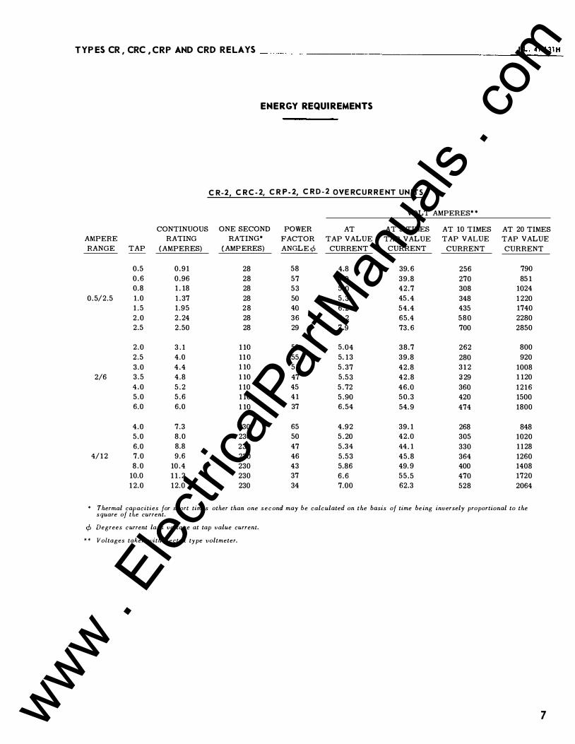
E N E RGY R EQUIR EMENTS
C R-2, C R C-2, C RP-2, C R D-2 OVE R C U R R E NT U N ITS
VOLT AMPERES tt CONTINUOUS ONE SECOND POWER AT AT 3 TIMES AT 10 TIMES AT 20 TIMES
AMPERE RATING RATING t FACTOR TAP VALUE TAP VALUE TAP VALUE TAP VALUE
RANGE TAP (AMPERES) (AMPERES) ANGLE¢ CURRENT CURRENT CURRENT CURRENT -------
0.5 0.91 28 58 4.8 39.6 256 790 0.6 0.96 28 57 4.9 39.8 270 851 0.8 1.18 28 53 5.0 42.7 308 1024
0. 5/2.5 1.0 1.37 28 50 5.3 45.4 348 1220 1.5 1.95 28 40 6.2 54.4 435 1740 2.0 2.24 28 36 7.2 65.4 580 2280 2.5 2.50 28 29 7.9 73.6 700 2850
2.0 3.1 110 59 5.04 38.7 262 800 2.5 4.0 110 55 5.13 39.8 280 920 3.0 4.4 110 51 5.37 42.8 312 1008
2/6 3.5 4.8 110 47 5.53 42.8 329 1120 4.0 5.2 110 45 5.72 46.0 360 1216 5.0 5.6 110 41 5.90 50.3 420 1500 6.0 6.0 110 37 6.54 54.9 474 1800
4.0 7.3 230 65 4.92 39.1 268 848 5.0 8.0 230 50 5.20 42.0 305 1020 6.0 8.8 230 47 5.34 44.1 330 1128
4/12 7.0 9.6 230 46 5.53 45.8 364 1260 8.0 10.4 230 43 5.86 49.9 400 1408
10.0 11.2 230 37 6.6 55.5 470 1720 12.0 12.0 230 34 7.00 62.3 528 2064
t Thermal cafacities for short times other than one second may be calculated on the basis of time being inversely proportional to the
square of t e current.
¢ Degrees current lags voltage at tap value current.
tt Voltages taken with Rectox type voltmeter.
7 www . El
ectric
alPar
tMan
uals
. com

TYPES CR, CRC,CRP AND CRD REL AYS ______________________ _
8
ENE RGY REQUI REMENTS
CR-5, CRC-5, CRP-5, CRD-5, CR-6, CRC-6, CRP-6, CRD-6 OVERCURRENT UN ITS
Ampere Range Tap
( 0.5 ( 0.6 ( 0.8
0.5/2.5 ( 1.0 ( 1.5 ( 2.0 ( 2.5
2/6
2 2.5 3 3.5 4 5 6
4 5 6
4/12 7 8
(10 (12
Continu ous Rating
(Amperes)
2.7 3.1 3.7 4.1 5. 7 6.8 7.7 8 8.8 9.7
·10.4 11.2 12.5 13.7
16 18.8 19.3 20.8 22.5 25 28
One Second Ratind
(Amperes)
88 88 88 88 88 88 88
230 230 230 230 230 230 230
460 460 460 460 460 460 460
Power Factor
Angle¢
69 68 67 66 62 60 58
67 66 64 63 62 59 57
65 63 61 59 56 53 47
At Tap Value
Current
3.92 3.96 3.96 4.07 4.19 4.30 4.37
3.88 3.90 3.93 4.09 4.12 4.20 4.38
4.00 4.15 4.32 4.35 4.40 4.60 4.92
VOLT AMPERES tt At 3 Times Tap Value
Current
20.6 20.7 21 21.4 23.2 24.9 26.2
21 21.6 22.1 23.1 23.5 24.8 26.5
22.4 23.7 25.3 26.4 27.8 30.1 35.6
At 10 Times Tap Value
Current
103 106 114 122 147 168 180
110 118 126 136 144 162 183
126 143 162 183 204 247 288
CR-7, CRC-7, CRP-7 & CRD-7 OVERCURRENT UNITS
Continuous Ampere Rating Range Tap (Amperes)
0.5 2.7 0.6 3.1 0.8 3.7
0.5/2.5 1.0 4.1 1.5 2.0 2.5
( 2 ( 2.5 ( 3
2/6 ( 3.5 ( 4 ( 5 ( 6
4 5
4/12 ( 6 ( 7 ( 8 (10 (12
5.7 6.8 7.7 8 8.8 9.7
10.4 11.2 12.5 13.7
16 18.8 19.3 20.8 22.5 25 28
One Second Rating t
(Amperes)
88 88 88 88 88 88 88
230 230 230 230 230 230 230
460 460 460 460 460 460 460
Power At Factor Tap Value
Angle ¢ Current
68 3.88 67 3.93 66 3.93 64 4.00 61 58 56
66 63 63 62 61 59 58
64 61 60 58 55 51 46
4.08 4.24 4.38
4.06 4.07 4.14 4.34 4.34 4.40 4.62
4.24 4.30 4.62 4.69 4.80 5.20 5.40
VOLT AMPEREStt
At 3 Times Tap Value
Current
20.7 20.9 21.1 21.6 22.9 24.8 25.9
21.3 21.8 22.5 23.4 23.8 25.2 27
22.8 24.2 25.9 27.3 29.8 33 37.5
At 10 Times Tap Value
Current
103 107 114 122 148 174 185
111 120 129 141 149 163 183
129 149 168 187 211 260 308
At 20 Times Tap Value
Current
270 288 325 360 462 548 630
308 342 381 417 448 540 624
376 450 531 611 699 880
1056
At 20 Times Tap Value
Current
278 288 320 356 459 552 640
306 342 366 413 448 530 624
392 460 540 626 688 860
1032
t Thermal capacities for short times other than one second may be calculated on the basis of time being inversely proportional to the square of the current.
¢Degrees current lags voltage at tap value current.
tt Voltages taken with Rectox type voltmeter.
www . El
ectric
alPar
tMan
uals
. com

TYP ES CR, CRC, CRP AND CRD R EL AYS _____________________ I.L _._4 _1- _13 _1_M ENE RGY REQUIREMENTS
CR-8, CRC-8, CRP-8 & CRD-8
CR-9, CRC-9, CRP-9 & CRD-9 OVERCURR ENT UNITS
Ampere
Range Tap
0.5
0.6
0.8
0.5/2.5 1.0
1.5
2.0
2.5
( 2
i 2.5
( 3
2/6 ( 3.5 ( 4
( 5
( 6
( 4
( 5
( 6
4/12 ( 7
( 8
(10
(12
Continuous
Rating (Amperes)
2.7
3.1
3.7
4.1
5.7
6.8
7.7
8
8.8 9.7
10.4
11.2
12.5
13.7
16
18.8 19.3
20.8
22.5
25
28
One Second
Rating t (Amperes)
88
88
88
88
88
88
88
230
230
230
230
230
230
230
460
460 460 460
460
460
460
Power
Factor Angle p
72
71
69 67
62
57
53
70
66
64
62
60
r.s 56
68
63
60
57
54 48
45
CR-11, CRC-11
At Tap Value
Current
2.38
2.38
2.40
2.42
2.51
2.65
2.74
2.38
2.40
2.42
2.48
2.53
2.64
2.75
2.38
2.46 2.54
2.62
2.73
3.00
3.46
VOLT AMPERES tt
At 3 Times Tap Value
Current
21
21
21.1
21.2
22
23.5
24.8
21
21.1
21.5
22
22.7
24
25.2
21.3
21.8 22.6
23.6
24.8
27.8
31.4
At 10 Times Tap Value
Current
132
134
142
150
170
200
228
136
142
149
157 164
180
198
146
158 172
190
207
248
292
At 20 Times Tap Value
Current
350
365
400
440
530
675
800
360
395
430
470
500
580
660
420
480
550
620
700
850
1020
CRP-11 & CRD-11 OVERCURRENT UNITS
CONTINUOUS ONE SECOND AMPERE RATING RATING t RANGE TAP (AMPERES) (AMPERES)
0.5/2.5
2/6
4/12
0.5 0.6 0.8 1.0 1.5 2.0 2.5 2.0 2.5 3.0 3.5 4.0 5.0 6.0 4.0 5.0 6.0 7.0 8.0
10.0 12.0
1.7 1.9 2.2 2.5 3.0 3.5 3.8 7.0 7.8 8.3 9.0
10.0 11.0 12.0 14 16 17 18 20 22 26
56 56 56 56 56 56 56
230 230 230 230 230 230 230 460 460 460 460 460 460 460
POWER AT FACTOR TAP VALUE ANGLE¢ CURRENT
36 34 30 27 22 17 16 32 30 27 24 23 20 20 29 25 22 20 18 17 16
0.72 0.75 0.81 0.89 1.13 1.30 1.48 0.73 0.78 0.83 0.88 0.96 1.07 1.23 0.79 0.89 1.02 1.10 1.23 1.32 1.8
VOLT AMPERES tt AT 3 TIMES TAP VALUE CURRENT
6.54 6.80 7.46 8.30
10.04 11.95 13.95 6.30 7.00 7.74 8.20 9.12 9.80
11.34 7.08 8.00 9.18
10.00 11.1 14.9 16.3
AT 10 TIMES AT 20 TIMES TAP VALUE TAP VALUE CURRENT CURRENT
71.8 75.0 84.0 93.1
115.5 136.3 160.0 74.0 78.5 84.0 89.0
102.0 109.0 129.0 78.4 90.0
101.4 110.0 124.8 131.6 180.0
250 267 298 330 411 502 610 264 285 309 340 372 430 504 296 340 378 �54 480 600 720
t Thermal capacities for short times other than one second may be calculated on the basis of time being inversely proportional to the square of the current.
¢Degrees current lags voltage at tap value current.
tt Voltages taken with Rectox type voltmeter..
9 www . El
ectric
alPar
tMan
uals
. com

TYP ES CR, CRC, CRP AND CRD REL AYS
10
Relay Range
Type Amps
CR { 2-6 4-12 { 0.5-2.5
CRC 2-6
{0.5-2.5 CRP
2-6 {0.5-2.5
CRD 2-6
* DIR E CTIONAL UNIT POLARIZING CIRC UIT B U R D E N
Relay Power Factor Type Rating Volt Amperes L. Angle¢
132* 5g0 Lag CR Volts 11.5
230 * * g0 Lag CRC Amperes 1.45
208* * * CRP Volts 11.2 2g0 Lead
CRD
Current 230** 1.45 g0 Lag
Unit Amperes
CRD 208 * * *
Voltage Volts
11.2 2g0 Lead
Unit
¢Degrees cu"ent leads or lags voltage at 120 volts on voltage polarized units and 5 amperes on cu�ent polarized units.
/':,. Voltages taken with rectox type voltimeter- Burden of Voltage polarized units taken at 120 volts -Burden of current polarized units taken at 5 amperes.
* Continuous rating.
** One second rating. 30 second rating. ***
D I R E C T IO N A L U N IT O P E R ATI N G C I R C U IT B U R D E N
VOLT AMPEREStt
At At 3 Times At 10 Times Continuous One Second Power Minimum Minimum Minimum
Rating Ratingt Fador Tap Value Tap Va lue Tap Value (Amperes) (Amperes) Angle ¢ Current Current Current
10 230 34.5 0.44 4.08 48.0 12 2go 25.0 0.53 5.0 59.2
230 44.0 0.033 0.30 3.3 230 42.5 0.58 5.2g 58.0
10 230 34.5 0.03 0.23 2.8 1 0 230 34.5 0.44 4.og 4g.o 10 230 45.0 0.07 0.59 6.6 10 230 45.0 1.04 9.9 106.0
¢Degrees current lags voltage at tap value current.
At 20 Times Minimum
Tap Value Current
182.0 236.0
14.2 240.0 11.5
182.0 26.0
420.0
� Thermal capacities for short times other than one second may be calculated on the basis of time being inversely 1 proportional to the square of the current.
1-t Voltages taken with Rectox type voltmeter.
www . El
ectric
alPar
tMan
uals
. com

TYPES CR, CRC ,CRP AND CRD REL AYS
r-- --------
liTH RELATIVE INSTANTANEOUS POLARITYAS SIIOWNTHE DIRECTIONALUIIIT COIITACTSCLOSE
FROHT 'v'IEW
57-D-4546
Fig. 1 1 . Internal Sc hematic of single trip directional con
trol relay Type CRP with Indicating Instantaneous
Trip Unit, in Type FT21 Case.
SE TTINGS
A. Overcurrent Unit (CO)
The overcurrent unit settings can be defined either by tap settings and time dial position or by tap setting and a specific time of operation at some current multiple of the tap setting (e.g. 4 tap setting, 2 time dial position or 4 tap setting, 0.6 seconds at 6 times tap value current).
To provide selective circuit b reaker operation, a minimum coordinating time of 0.3 seconds plus breaker time is recommended between the relay being set and the relays with which coordination is to be effected.
The connector screw on the terminal plate above the time dial makes connections to various turns on the operating coil. By placing the screw in the various terminal plate holes, the relay will respond to multiples of tap value currents in accordance with t�e various typical time-current curves.
Caution
Since the tap block connector screw carries operating current, be sure that the screw is turned tight. In order to avoid opening the current transformer circuits when changing taps under load, con
nect the spare tap screw in the desired tap position
before removing the other tap screw from the original
I.L. 41-131M
- -,
� /UPPEJIDIRECTIOUL t UIIIT
I LOWER DIRECTIOIIAl - )- - "1 ""
I"'--r -1-, ! I NDICATING ------COIITACTOR SWITCH
0 [} l_ ,....... � I LL _T, I
FRONT VIEW
�UPPER OIRECTIOIIAL UNIT
lOW£RIHRECTIOIIAl UNIT
IIIOUCTION UIIIT -------
IMOICATIIIG /IIISTAIITAUOUS TRIP
� CHASSIS OPERATED SIIOIITIIIGSWITCH REDHNIOL.E TEST SWITCH CUJIREHT TEST JACK TEIIMUIAL.
57-D-4560
Fig. 12. Internal Schematic of single trip directional control
relay Type CRD with Indicating Instantaneous
Trip Unit, in Type FT31 Case.
tap position.
Instantaneous Reclosing
The factory adjustment of the CO unit contacts provides a contact follow. Where circuit breaker reclosing will be initiated immediately after a trip by the CO contact, the time of the opening of the contacts should be a minimum. This condition is obtained by loosening the stationary contact mounting screw, removing the contact plate and then replacing the plate with the bent end resting against the contact spring.
For double trip relaYs. the upper stationary contact
is adjusted such that the contact spring rests solidly
against the back stop. The lower stationary contact is
then adjusted such that both stationary contacts make
contact simultaneously with their respective moving
contact.
B. Inrlicating Contactor Switch (ICS)
The only setting required on the ICS unit is the
selection of the 0 2 to 2 0 ampere tap setting This
selection is made by connecting the lead located in front of the tap block to the desired setting by means
of the connecting screw.
c. Indic ating Instantaneous :rrip (liT) The core screw must be adjusted to the value of
pick-up desired.
11 www . El
ectric
alPar
tMan
uals
. com

TYP ES CR,CRC, CRP AND CRD RELAYS _____ ______________ ___ _
12
I� 1\1 C U R V E lH8 2lil.i
t---t-------r--+-+--t-+-+--+-1--t+!---JH-++--�+-� �. -++-' f-+H-+++++++++++tN-Jf++-rl�+-t-t-'+'-,-.-ri+-' T Y P I CAL T I M E CU R V E S r-�����-+��������\1+�'H+�rt+H+1,�r�,a+��'�c'��'+'� ����
TYP E C0-
2
r---t-+--+-+-+H�+-+l+-l--!-\--i-,\---4--1\-+-++H+++-++-++++t-4++1++-+�-+---J.-++1 • --+-J-..- 0 V E R CU R R EN T R E L A Y "' � 50-60 CYCLES
�+-+-+-+-�����+,�,,��,�,,�,�����������,-4� 1 \ \ --:--�
�+--+--+--+-+--+-+-+ 1/2 N
ll " 1\ \ '
\ '\I '\ ' '
"""'" I
' '""
'
' .,
,,
I '
I
' ,,
....... I
'
' I I
_,_ . �
--+-...:d-l 1ll
QL-L-����������LU�������������������� 1 2 3 l.i 5 6 7 8 9 10 12 14 16 18 20
MU LTIPL ES OF TAP VA L U E C U R R ENT
Fig. 13. Typical Time Curves For Relays With C0�2 Units.
www . El
ectric
alPar
tMan
uals
. com

TYP ES CR, CRC, CRP AND CRD R EL AYS _______ ______ ________ 1 · L_. _4_l·_IJ_l _M
140
120
100
en 0 z 0 u 141 en
80
60
lJO
20
I
I '
'
I
I
I
___:_______ -+-· -r-
-1--.1 -t _ _ -f--
---} I
=tt --
1-- ---1---
I-
' ' \ \I\ \ ' '
'\ \ \ ' \ \ ' \ '
1\ ll ll _l \ \ \ \ \
1\ 1\ \ \ \ \ \ \
\ \ \ 1\ 1\ \ \ \ \ \ \ \ 1\ \ 1\ \ \ ' 1\. \
' 1\ 1\. \ 1\ \. \.
1\ ' 1'-I\. ' I'-�
' ' I'
.......... r
�1/2 l I
I
I I
'
'
'
� \ -�
1\ ' ' 1\ '
' ' I\ \ '"' �
-�
' r\---\.
""
.... � ... J"oo,
I' 4 3 �
2 I'-
"""
2
I I '
'
I
I I
l I,
I I I I
I
I I
1 ' ' I I I I ' I I
I I ' I
I I jl ' ' , 'I , I I I 1 . 1, '' I I i ' ! '
I l_l i I I I
I jl I
! ' I
I ' i' I
_l , I !
' ! I '
� I N. :" ' I
I " "'
' l 10 .,... 9 '
.... I ... 8 7 I
6 !'r 5 �
·I'-
3
CU R V E 418245 . ' TYP I CAL T I M E cu RVES
I TYPE C0-5
OVER CU RRENT RE L AY I 50-60 CYC L ES
I
l 1, II II I i ' :11:1 I l l I I
_i I J II
I ' I I ' , I' II !II il I I
! I I I 'I ' ' I
: ' I I I I .I
I !'II I II I I I I I II ' I
I i I I I, I ' I I I I
I
ll 1 I '
I I ' Ill I I I I ' I , : ' I 'J _!_ Ill' Ill II l 1 11 , 'Ill • Ill I !
I ! , I I Ill i ' I I
! II I I I J II I l
I
II I ill I I I
T I M E D I AL SETT I N G
1{Y II 1111, "" If
i .,jJ_ o.!o.l.. ,..
:11!1
5 6 7 8 910
MU L TIP L ES OF TAP VAL U E CU RRENT
Fig. 14. Typ ical T ime Curves For Re lays W ith C0-5 Units.
13 www . El
ectric
alPar
tMan
uals
. com

TYPES CR,CRC,CRPANDCRDRELAYS ______________________________________________ _
14
<f) 0 z 0 (..) LLI Cl)
7
6
5
3
2
1
1-ll
\
\I\ \
\ \ 1\
1\ 1\
\ \
\ \ \ I 1\
\ 1\ \ I
\ \
1\ I \ 1'\. I
--�n tt\+, �-�---+ -
-+---
\ ,, -� �- 1\.
1\ ''" 1- ;\ 1-- " �-
I
I I I I
I I I I
I ' I ! I
I I I I
I I 1•1
I I I
,, I
I I I
"'. i N..
TIME " 1'
1"- ..... � I, N..i I fl"ll '� NJI'
' � ;i�f1t f-:" 10..; '
['I ·-r- �r�IS 9 .,.tf - : 1 ' . ....: I '""' ,'1�8 �· ""' ' � rq; :' ' 1"1. ' 7 t -,..j'
,.;;
CURVE lH82�6 I TYPICAL TIME CURVES
TYPE C0-6 i I I O VER CURRENT RELAY II I I !50-60 CYCLES .
--'� I �-,- - r-r--;-I
·-I I ' I ���
I
I I I' I I I
II I
I I I I
I I I I 1
I I I ' I i' I I
I D I AL SETTING
I I' I I � I +-
r-= I I • ""' ., N.;_ l' '__). b,.-�. l'ti' I � I�
!". 1'.. I ' .... ...... I
i'!-1-- t- -t� �-1- ---- -�'i--1"- - .... 1--,
� r 5t'S- - ,...... I , 1+ I 1--
-I ---+-- ---+ --+-
--�-t--4-�-+-
-I -4--+---� -��-+-
'�I H' -., t - " I 3 lli ··- . � ! �t'i JJ_ltf - -i
"'. �� 2 ,...:;.... . I -,...., �jj, l.r- -' d: 1- 1/2... - f - -� I-t- r-rt r-r-· I f-+-
- �
t +
.;j;;
H-: �,li I ' '
� I 'I I
. I I
+ r-1- 1-1-1-l-
2 3 5 6 7 8 9 10 12 1� 16 18 20
MULTIPLES OF TAP VA LUE CURRENT
Fig. 15. Typ i cal time curves for relays with C0- 6 un its.
www . El
ectric
alPar
tMan
uals
. com

TYPES CR,CRC,CRP AND CRD RELAYS ____________________ I_.L_._41_- _13_1 M_
(./) 0 z 8 UJ (./)
7
-
6
5
3
_ _ J
--
2 '
1
0 1
\ \
I l
\
\
'"
.....
'
1\
f \
l '
\
1\
'
T
\
\
\
"
�"'\:
...... 1
f;;' 1/2 _,·
2
CURVE �182�7 i ' TYP I CAL T I ME CURVES ' TYP E C0-7 I '
' O V E R CURRENT R E L AY ' I 50-60 CYCL ES
I
' ' '
' '
' I '
I
'
' I : I I T I ME D I AL SETT I N G
I ' 11
10 9 ........ 18 ........ .I
7 ......._ ...... ....... ...... ...... ....
6 I � ........ ....;; ...... - .... 5 ' -- .... - -;....
� � -� � -;.... . I -3 - -�----r-
- r-2
I---
3 5 6 7 8 9 10 12 1� 16 lB 20 MU L T I P L ES OF TAP VAL U E CU RRENT
Fig. 16. Typ i ca.l t i m e curves for r elays with C0-7 units.
15 www . El
ectric
alPar
tMan
uals
. com

TY P E S CR, CRC, CRP AND CRD RE LAYS· ______________ ----------
1 6
<n 0 z 0 u 1.1.1 <n
7
6 I I
5 I
I
3
1-
2
1
0
1
\
\
� " "
1'-.
\
1 \
1\
' 1
1/2
2
2
CURVE 4 1 92�
I TYP I CAL T I M E CU R V ES · i ' I
co'-8 ' I ' ' TYPE ' ' I OVER CUR R EN T R EL A Y
I
I I I 50- 60 CYCL ES I i '
I '
I I I ' ' '
I '
: ' ' I I
I
1 I ! '
I I I I
I I
' :
T T I ME D I AL SETT I NG I
1 1 I I ; ' , I
10.._ i"'o.· I I ""'-9 I ! !Ill '
8 i : I
N.:· I
7 ,"!.
6 ' i I
I " I I .....
5 .. I I "" ' ....... l.+ N. ' !""'. I'
I [""oo. 1' 3 ......... ,..., : ......... ....,...,
.... I ..... """' ...... --� - r-b r--..
...... r--l"oo. --�--.
' - ,.._
3 l.+ 5 6 7 $ 9 10 12 1l.+ 16 lB 20 MULT I P L ES OF TAP VALUE CURRENT
Fig. 1 7. Typ ical t ime curves for r el ays with C0- 8 units.
www . El
ectric
alPar
tMan
uals
. com
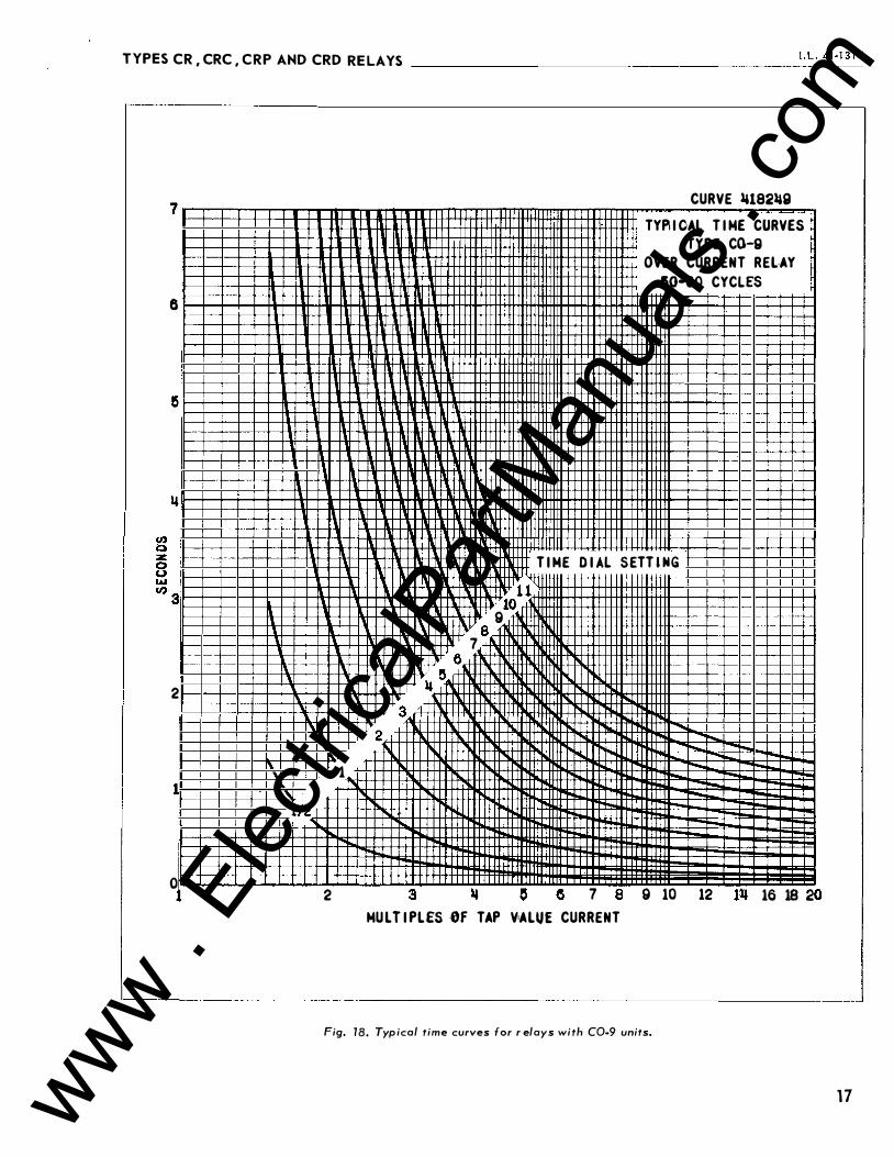
TYPES CR,CRC,C RP AND CRD REL AYS ____________________ ,_. L_. 4_1_-l_J l_M
7 CURVE �1821&9 -. TYP. I OAL T I ME CURVES ·
TYPE C0-9 I OVER CURRENT REL·AY
!50•60 CYCLES
8
:
I
1 \
T I ME D I AL S ETT l NG
tf' 1 \ 10
9 \ 8
7 6
1\ ll 5 2
3 I
2 ....... I .....
"""" -..... - ._...,
i 1 � � - -....
--' ......
1/2 --
0 2 3 1& 0 6 7 8 9 10 12 lll 16 18 2 0
MU L T I PL£5 OF TAP V1ALUE CURRENT
Fig. 18. Typ ical time curves for r elays with C0-9 units.
1 7 www . El
ectric
alPar
tMan
uals
. com

TYPES CR, CRC, C R P A ND CRD RELAYS __________________________________________ __
1 8
R 8
100 90 80 70 60
50 �0
30
20
10 9 8 7 6 & �
3
2
� 1 .0 "' 0.9 - 0. 8 � 0.7 ;:: 0. 6
0.5
0 . 11
o.�
0.2
0.1 0.09 0.08 0.07 0.06
0.05
0.011
0.03
0.02
0.01 1
2 3 II It 6 7 8 9 10
\� .\\\1\\\ \\U\\\\ .\ �\\\\\ \ �\\\� \ �\\� � 1\\\ � � , \
\ \ l\\l\ \ \ \ \ \' l \\ 1.'\ \ \ \ \
\ 1\ \ \ \ \
\
.\ l\' �� \' l\' �\'i\
\I\ .\' l\.\ \ l\.'.W
\ 1\ 1\�\\\ \ ' l\1\ �' � 1\ �I\ � � � \ �I\ � � � � �\
\ 1 '\ l''\ '\. ' 1'\ L'\.
1.\. 1.\. 1\. l'\. \ 1\ \ 1\ � \ I\ i\ \ l'\ '\.
\ 1.\. 1\. " \ '\
I \ i\ " 1\ i\ [\ r'\� '\
' '"
'\. '\
'
2 3 II & tl 7 8 9 10
·' "� l' t"t--
"' r--
' r--,, " r\ '
' '
r--
MULTI PLES Of Tl# VAUI£ CII&REIIT
20 30 110
� :--...: r-... :"'-l'
� !'-...: """ � I" " t.... .......... 1'--"""
1'-- �"-- -......... -
r-...
r-.. r-
......... i'-
20 30 IJO
1 1 10 9 I 7 • !i
3
2
1/2
Fig. 19. Typ i cal time curves fo r relays with CO- 1 1 uni ts.
2988655 TYP I CAL T I ME CURVES
TYPE C0- 1 1 OVER CURRENT RELAY
50-00 CYCUS
T IME DIAL SETIIM&
www . El
ectric
alPar
tMan
uals
. com

TYPES CR, CRC , CR P AND CRD R EL AYS
CR RELAY FROtH VIEW
AMMETER
f - USE DASHEDCOIIMECTION I NSTEAD OFSOLII> OJIE FOR RELAYS WITH 0.5-2.5 Al!tPERE R.I.IIGE Co-5 AIIO C0-6 UNITS.
} TO TIMER !TIMEII STOPS WHEN I STOP AUX.. RELAY COMTACT OPENS )
Sill ITCH .,.
o-i-�-�-�---0--f-�-0 � 120 YOLTS � 60 CYC.
25/S ACT
l 82A873
Fig. 20. Diagram of test connections of the overcurrent unit.
The namepl ate data will furnish the actual current range th at may be obtained from liT unit.
D. Directional Unit ( D)
No setting is re quired.
INSTALLATION
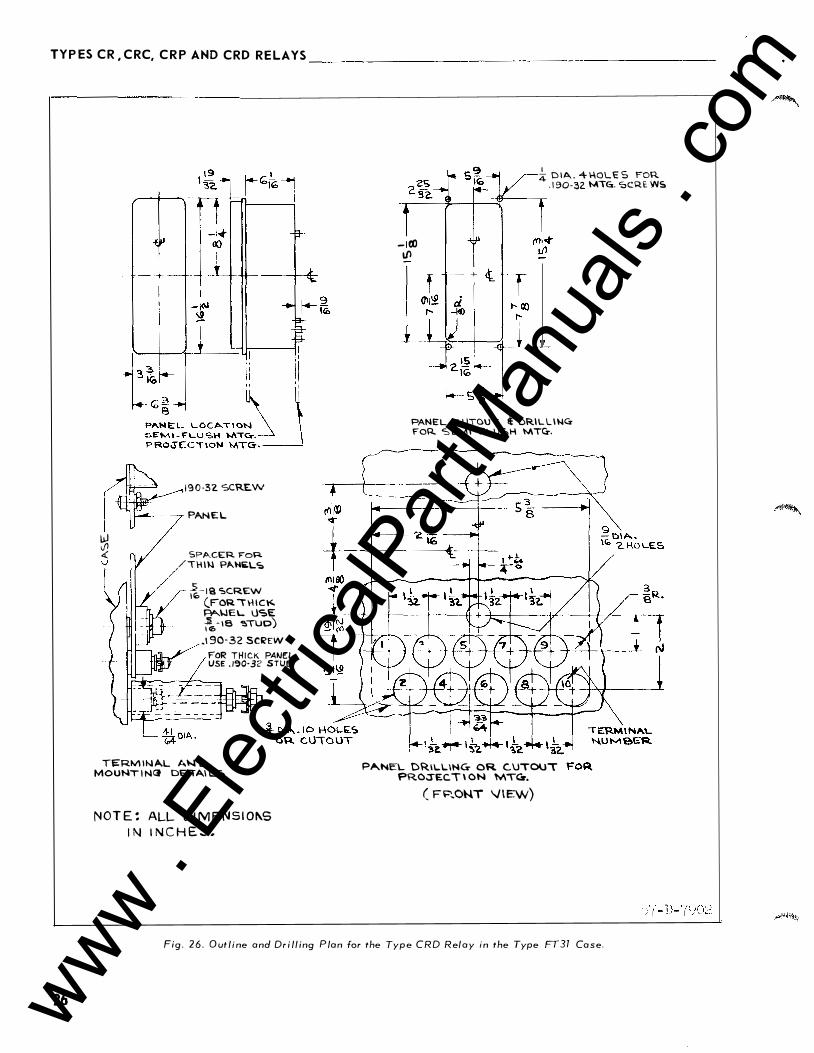
The relays should be mounted on switchboard panels or their equivalent in a location free ftom dirt, moisture, excessive vibration and heat. Mount the relay vertically by means of the two mounting studs for the type FT projection case or by means of the four mounting holes on the flange for the semiflush type FT case. Either of the studs or the mounting screws may be utilized for grounding the relay. The electrical connections may be made directly to the terminals by means of screws for steel panel mounting or to terminal studs furnished with the relay for thick panel mounting. The terminal studs may be easily removed or inserted by locking two nuts on the studs and then turning the proper nut with a wrench.
The external a-c connections of the directional
overcurrent relays are shown in Figs. 2 1 to 24.
ADJUSTMENTS AND MAINTENANCE
The proper adjustments to insure correct operation of this relay have been made at the factory. Upon receipt of the relay, no customer adjustments, other than those covered under "SETTINGS " , should be required.
For relays which include an indicating instantaneous trip unit (liT), the junction of the induction and indicating instantaneous trip coils i s brought out to switch jaw 113. With this arrangement the overcurrent units can be tested separately.
STATIO/II dUS
1 2 3
POS. T R I P !JUS
.. �....::..:.__:.::.;;....:::..__ NEil.
67-J. 67-3
I . L . 4 1 · 1 3 1M
PHASE ROTATION 1-2-J
Pt1-l
PH-2
Pt1-J
'" ::�:.\ ��;r�:" '!_
'J l
�ECTOR$ AT 1� P . F . POWER IH T R I P P I N i:i D I R E C T I ON
D H I C E NUfoldER CHART
67 - D I RE C T I ONAL OVERCURREIIT RELAY-TYPE CR
�2 - POWER C I RCU I T 8REAKER
ICS - IMDICATIHG COJ'ITACTOR SWITCH
a - tiREAKER AUXILIARY CONTACT
TC - BREUER TR I P C O I L
l 82A7 93
Fig. 2 1 . External Schematic of the type CR Relay for phase fault protection.
Acceptance Check The following check is recommended to insure
that the rel ay is in proper working order:
A. Overcurrent Unit (CO) The directional unit contacts must be in the
closed position when checking the operation of the overcurrent unit.
1. Contact a) By turning the time dial, move the moving con
tacts until they deflect the stationary contact to a position where the stationary contact is resting against its backstop. The index mark located on the movement frame should coincide with the "0 " mark on the time dial. For double trip relays, the foll o w on the stationary contacts should be approximately 1/64".
b) For relays identified with a "T", located at lower left of stationary contact block , the index mark on the movement frame will coincide with the "0 " mark on the time dial when the stationary contact has moved through approximately one-half of its normal deflection. Therefore, with the stationary contact resting against the backstop, the index mark is offset to the right
1 9 www . El
ectric
alPar
tMan
uals
. com

TYPES CR , CRC, CRP AND CRD REL AYS-----------------------
STATION !SuS
Of� ICE IIUMBEtt CHART
67M - D I RE�TIOMAL OHRCLJfti(EMT VKOuttD RELAl' TYPE CKP
�� - UYEKCUIIREMT UHI T OF TlPE CliP
� - DIRECTIONAL UM I T Of T'I'PE CRP
�L - PO WElt C I KCU IT dREA.:£�
IC;;. - IMOICATIMU Wr'ITACTUR SWITCH
a - 6REAKER AUXII.. IAIO COdACT
r.; - dltEAJO:EK T R I P COIL
182A792
Fig. 22. External Schemat ic of the type CRP Relay for ground fault protection.
of the "O" mark by approximately . 020 ". The placement of the various time dial positions in line with the index mark will give operating times as shown on the respective time-current curves. For double trip relays, the follow on the stationary contacts should be approximately 1/32".
2. Minimum Trip Current - Set the time dial to position 6. Alternately apply tap value current plus 3o/c and tap value current minus 3o/c . The moving contact should leave the backstop at tap value current plus 3o/c and should return to the backstop at tap value current minus 3o/c .
3 . Time curve - Table 2 shows the time curve calibration points for the various types of relays. With the time dial set to the indicated position , apply the currents specified by Table 2 (e ,g. for the CR-8, 2 and ·20 times tap value current) and measure the operating time of the relay. The operatin g times should e qual those of Table 2 plus or minus 5 percent.
For type CR- 1 1 relay only, the 1. 30 times tap value operating time from the number 6 time dial position is 54.9 ± 5% seconds. It is important that the 1 . 30 times tap value current be maintained accurately. The maintaining of this current accurately is necessary
20
STATION tiUS
1 2 3 DEVICE liUMOER CHART
67ft - OIRECTIOIAL OVERCUII.KENT ijRQUIID RELAY
TYPE CRC w - OVERCURREKT UNIT OF TYPE CRC
6� - DIRECfiOKAL UII I T Of fYPE CRC
52 - POWER C I RCUIT illiEAKEII:
ICS - lltOICATIItG COMTACTOR SWITCri
a - 8REAKER AUX I L IARY CONTACT
TC - BREAKER TRIP COIL
182A790
Fig. 23. External Schematic of the type CRC Relay for ground fault protection.
because of the steepness of the slope of the timecurrent characteristic (Fig . 19). A 1% variation in the 1. 30 times tap value current (including measuring instrument deviation) will change the nominal operating time by approximately 4%.
B. Indicating Contactor Switch (ICS) - Close the main relay contacts and pass sufficient d-e c urrent through the trip circuit to close the contacts of the ICS. This value of current should not be greater than the particular ICS tap setting being used. The indic ator target should drop freely.
The contact gap should b e approximately .047" between the bridging moving contact and the adjust
able stationary contacts. The bridging moving con
tact should touch both stationary contacts simultaneously,
* c. Indicating Instantan eous Trip Uni t ( liT)
The core screw must be adjusted to the value o f
pick-up current desired.
The n ameplate data will furnish the actual c urrent
ran g e that may be obtained from liT uni t .
www . El
ectric
alPar
tMan
uals
. com
TYPES CR ,CRC, CRP AND CRD R E LAYS I . L . 41·131M -------------------------------------------------------------
I 2 3
E
DC TRIP BUS
0 '
2 c
f67K JCS
52 • ·:· 2 "'L
DEVICE NUMBER CtiAU
67H � DIRECTIOJII.l OYERCURII:EU GROUID RELAY TYPE CRD
6�� - OVERCURiEMT UNIT OF TYPE CRD
� - LOWER DLIECTIGII.L. UIIT Of TYP'E CRD
� - llr!J£1 DI RE<:TICIIAL UIIT Of TYftf CiiD
52 .. POW£1 CIRCUIT IIUIEil
ICS • I.ICATIIQ caiTACTGa SII TCM
• • IIIWEI AUXILIAIY COITACT
TC - iiE.AlEII TIIP' COIL
182A791
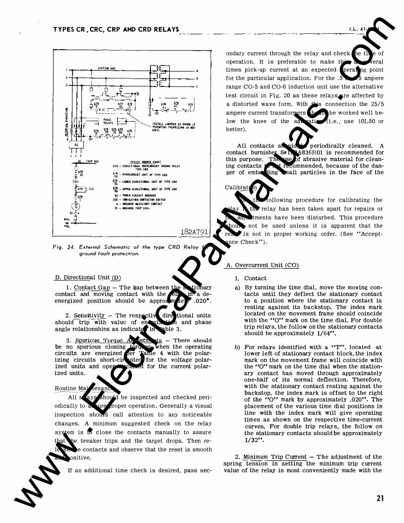
Fig. 24. External Schematic of the type CRD Relay for ground fault protection.
D. Directional Unit (D)
1 . Contact Gap - The gap between the stationary contact and moving contact with the relay in a deenergized position should be approximately . 020".
2 . Sensitivity - The respective directional units should trip with value of energization and phase angle relationshins as indicated in Table 3 .
3 . Spurious Torque Adjustments - There should be no spurious closing torques when the operating circuits are energized per Table 4 with the polarizing circuits short-circuited for the voltage polarized units and open-circuited for the current polarized units.
Routine Maintenance
All relays should be inspected and checked peri
odically to assure proper operation . Generally a visual
inspection should call attention to any noticeable
changes. A minimum suggested check on the relay
system is to close the contacts manually to assur e
that the breaker trips and the target drops. Then re
leas e the contacts and observe that the reset is smooth
and positive.
If an additional time check is desired, pass sec-
ondary current through the relay and check the time of
operation. It is preferable to make this at several
times pick-up current at an expected operating point
for the particular application. For the . 5 to 2. 5 ampere
range C0-5 and C0-6 induction unit use the alternative
test circuit in Fig. 20 as these relays are affected by
a distorted wave form. With this connection the 25/5
ampere current transformers should be worked well be
low the knee of the saturation ( i . e. , use 10L50 or
better).
All contacts should be p eriodically cleaned. A contact burnisher S# 182A836H01 is recommended for this purpose. The use of abrasive material for cleaning contacts is not recommended, because of the danger of embedding small particles in the face of the
Calibration
Use the following procedure for calibrating the
relay if the relay has been taken apart for repairs or
the adj ustments have been disturbed. This procedure
should not be used unless it is apparent that the
relay is not in proper working order. ( See "Accept
ance Chec k " ) .
A. Overcurrent Unit (CO)
1. Contact
a) By turning the time dial , move the moving contacts until they deflect the stationary contact to a position where the stationary contact is resting against its backstop. The index mark located on the movement frame should coincide with the "0" mark on the time dial. For double trip relays, the follow on the stationary contacts should be approximately 1/64".
b) For relays identified with a "T" , located at
lower left of stationary contact block, the index mark on the movement frame will coincide with the "0" mark on the time dial when the stationary contact has moved through approximately one-half of its normal deflection. Therefore, with the stationary contact resting against the backstop, the index mark is offset to the right of the "0" mark by approximately .020". The placement of the various time dial positions in line with the index mark will give operating times as shown on the respective time-current curves. For double trip relays, the follow on the stationary contacts should be approximately 1/32".
2 . Minimum Trip Current - The adjustment of the spring tension in setting the minimum trip current value of the relay is most conveniently made with the
21 www . El
ectric
alPar
tMan
uals
. com
TYP ES CR , CRC, CRP AND CRD RELAYS'------------------------
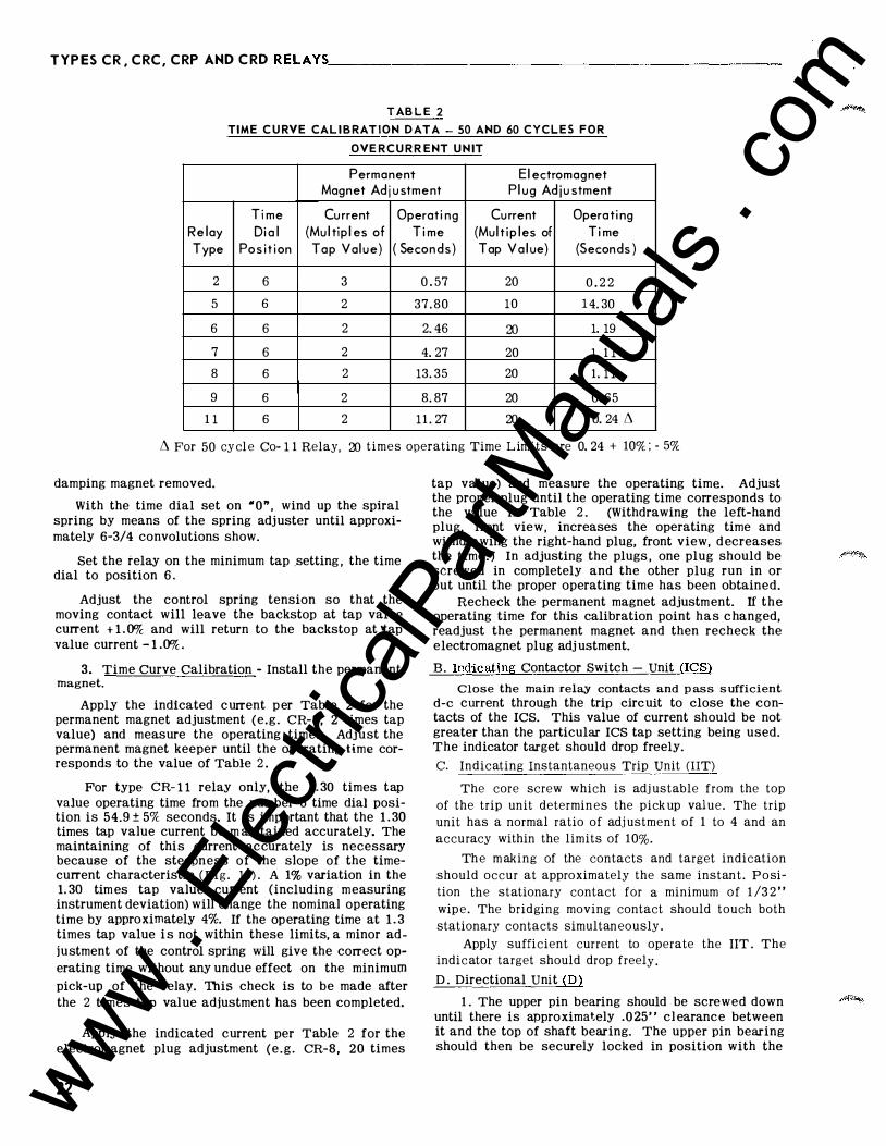
T AB L E 2
TIME C U RVE CAL I B RAT I O N D AT A - 50 AND 60 C Y C L E S F O R
OVE RC U RR E NT U N IT
Permanent Electromagnet Magnet Ad j u stment Plug Ad ju stment
Ti me Current Operati ng Current Operating Relay Dial (Multiples of Ti me (Mult iples of Ti me Type Pos i t ion Tap Value) ( Seconds) Tap Value) (Seconds )
2 6 3 0 . 57 20 0 . 2 2
5 6 2 37. 80 10 1 4. 30
6 6 2 2. 46 20 1. 19
7 6 2 4. 27 20 1. 1 1
8 6 2 13. 35 20 1. 1 1
9 6 2 8. 87 20 0 . 65
1 1 6 2 1 1 . 27 20 0. 24 L'l
L'l For 50 cycle Co- 1 1 Relay, 20 times operating Time Limits are 0. 24 + 10% ; - 5%
damping magnet removed.
With the time dial set on " 0 " , wind up the spiral spring by means of the spring adjuster until approximately 6-3/4 convolutions show.
Set the relay on the minimum tap _setting , the time dial to position 6.
Adjust the control spring tension so that the moving contact will leave the backstop at tap value current + 1 . 0% and will return to the backstop at 'tap value current - 1 .0%.
3. Time Curve Calibration - Install the permanent magnet.
Apply the indicated c urrent p er Table 2 for the permanent magnet adjustment (e.g. CR-8, 2 times tap value) and measure the operating time. Adjust the permanent magnet keeper until the operating time corresponds to the value of Table 2 .
For type CR- 1 1 relay only, the 1 . 30 times tap value operating time from the number 6 time dial position is 54.9 ± 5% seconds. It is important that the 1 . 30 times tap value current be m aintained accurately. The maintaining of this current accurately is necessary because of the steepness of the slope of the timecurrent characteristic ( Fig. 19) . A 1% variation in the 1. 30 tim es tap value current (including measuring instrument deviation) will change the nominal operating time by approximately 4%. If the operating time at 1 . 3 times tap value i s not within these limits, a minor adjustment of the control spring will give the correct operating time without any undue effect on the minimum
pick-up of the relay. This check is to be made after the 2 times tap val ue adjustment has been completed.
Apply the indicated current per Table 2 for the electromagnet plug adjustment ( e . g . CR-8 , 20 times
22
tap value) and measure the operating time. Adjust the proper plug until the operating time corresponds to the value in Table 2 . (Withdrawing the left-hand plug, front view, increases the operating time and withdrawing the right-hand plug, front view, d ecreases the time . ) In adjusting the plugs , one plug should be screwed in completely and the other plug run in or out until the proper operating time has been obtained.
Recheck the permanent magnet adjustment. If the operating time for this calibration point has c hanged, readjust the permanent magnet and then recheck the electromagnet plug adj ustment.
B. Indicating Contactor Switch - Unit (ICS)
Close the main relay contacts and p ass s ufficient
d-e current through the trip circuit to close the contacts of the ICS. This value of current should be not greater than the particular ICS tap setting being used. The indicator target should drop freely.
c. Indicating Instantaneous Trip Unit (liT)
The core screw which is adj ustable from the top
of the trip unit determines the pick up value. The trip
unit has a normal ratio of adj ustment of 1 to 4 and an
accuracy within the limits of 10%.
The m aking of the contacts and target indication
should occur at approximately the same instant . Position the stationary contact for a minimum of 1 /3 2 "
wipe. The bridging moving contact should touch both
stationary contacts simultaneously .
Apply sufficient current to operate the liT . The indicator target should drop freely .
D . Directional Unit (D) 1 . The upper pin bearing should be screwed down
until there is approximat;ely . 025 " cl earanc e between it and the top of shaft bearing. The upper pin bearing should then be securely locked in position with the
www . El
ectric
alPar
tMan
uals
. com
TYPES CR, CRC, CRP AND CRD R ELAYS ____________________ 1_· L_. _4 _1 - _1 3_1 M
lock nut. The lower bearing position is fixed and cannot be adjusted.
2. The contact gap adjustment for the directional unit is made as follows:
With the moving contact in the normally-opened position , i .e . against the right stop on bridge, screw
in the stationary contact until both contacts just
close as indicated by a neon lamp in the contact cir
cuit . Then, scr ew the stationary contact away from
the moving contact 3/4 of a turn. Th e cl amp holding
the stationary contact housing need not be loosened
for the adjustment since the clamp utilizes a spring
type action in holding the stationary contact in
position.
The s et screw in the stationary contacts has
been shop adjusted for optimum follow and this ad
justment should not be disturbed.
The moving contact assembly has been factory
adjusted for low contact bounce performance and
should not be changed.
3 . The sensitivity adjustment is made by varying the tension of the spiral spring attached to the moving element assembly. The spring is adjusted by placing a screwdriver or similar tool into one of the notches located on the periphery of the spring adjuster and rotating it. The spring adjuster is located on the underside of the bridge and is held in place by a spring type clamp that does not have to be loosened prior to making the necessary adjustments.
The spring is to be adjusted such that the contacts will close as indicated by a neon lamp in the contact circuit when energized with the required current and voltage as shown in Table 3 . This table indicates that the spring can be adjusted when the
.phase angle relationship between the operating circuit and the polarizing circuit is at the maximum torque angle or when the circuit relationship has the operating and polarizing circuits in phase. It is recommended that a single phase (in phase relationship) set-up be used as a matter of ease and convenience.
4. The magnetic plugs are used to reverse any unwanted spurious torques that may be present when the relay is energized on current alone .
The reversing of the spurious torques is accomplished by using the adjusting plugs in the following manner:
a) Voltage circuit terminals on the voltage polarized relays (CR , CRP and CRD voltage polarized
unit) are short-circuited.
b ) The polarizing circuit of the current polarized relays (CRC and CRD current polarized unit) are open-circuited.
Upon completion of either "a" or "b", current is applied to the operating circuit terminals as per Table 4.
Plug adjustment is then made per table 4 such that the spurious torques are reversed. The plugs are held in position by upper and lower plug clip s . These clips need not be di sturbed in any manner wh en making the necessary adjustment.
The magnetic plug adjustment may be utilized to positively close the contacts on current alone. This may be desired on some installations in order to insure that the relay will always trip the breaker on zero potential .
R EN EWAL PARTS Repair work can be done most satisfactorily at the
factory. However, interchangeable parts can be furnished to the customers who are equipped for doing repair work . When ordering parts , always give the complete nameplate data.
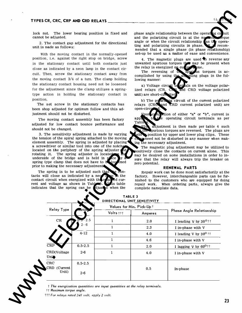
TAB L E 3
Relay Type Rating
CR 0 5 - 2 , 5
2 - 6
4-12
CRP 0.5-2.5 CRD(Voltage 2-6 Unit)
CRC 0.5-2.5 CRD (Current
Unit) 2-6
DIR ECTIO NAL UNIT S E NS ITIVITY
Values for Min. Pick-Up t
Volts ttt
1 1 1 1 1 1
Amperes
2.0 2.3 4.0 4.6 2.0 4.0
0.5
t The energization quantities are input quantities at the relay terminals. tt Maximum torque angle.
ttt For relays rated 240 volt, apply 2 volt.
Phase Angle Relationship
I leading v by 30° tt I in-phase with V
I leading V by 3 0° tt I in-phase with V
I lagging v by 60°tt I in-phase with V
In-phase
23 www . El
ectric
alPar
tMan
uals
. com

T Y P E S CR, CRC, C R P AND CRD RE LAYS _____________________ _
T A B L E 4 D I RECTIONAL U NIT C A L I B R A T I O N
Current Both Pl ugs In Relay Rating Amperes Cond ition Adjustment
0.5 to 2.5 Spurious Torque In Right (Front-View) Plug 2 to 6 40 Contact Closing Screwed Out Until
Direction (Left Spurious Torque is 4 to 12 80 Front View) Reversed
0.5 to 2.5 Spurious Torque In Left (Front View) Plug 2 to 6 40 Contact Opening Screwed Out Until
Direction ( Right Front Spurious Torque is in
View) (Contacts remain Contact Closing Direction,
4 to 12 80 open) Then the plug is screwed in until spurious torque is reversed.
24 www . El
ectric
alPar
tMan
uals
. com

TYPES CR , CRC, CRP AND CRD REL A YS ______________________ 1
·_L_. _41 _· 1_3_1 M_
_j� l i �� " ! I PA:!� LOCA\\O�J 5E.M i -FLUSH M\�.� PRO\iECT \ 0 � MT6.
& _________ . 1'30·32. SCREW � �- P,b.NEL '
w � SPACER FOR v T\-I IN PANELS
� -18 SC.RE.W IE> (FOR. \1-\ICK
PANEL USE fG- 18 STUD) , r qa - 3'2. SCREW
TERMIN�L AN D MOUNT I N G- DE"'IAI LS
NOTE : A L L. D \ M E N� \ O N S I N I N C H E S
l DI,C.... .4- HOLES FO� + . 190·3'2. MTC:r. SCREW$
PANEL CUTOUT .. DRILL\ WGl'"OR. SEMI-FLUS\-1 IIATG:.
I I 13� 13'2. PAWE:\... DR.\LLI NG- OR CUTOUT FOR
?RO;:I'E.C'T\0� MTG. (rR.OHT V\E.W)
57-D- 7901
Fig. 25. Outline and Drill ing Plan for the Type CR, CRC and CRP Relays in the type F T2 1 Case.
25 www . El
ectric
alPar
tMan
uals
. com
TYP ES CR , CRC, CRP AND CRD RELAYS ______________________ _
26
I � v
190·3'2. SCRE.W
PANEL
SPACER FoR /IHI� PA.Ni:LC:.
_5 _ \ Q ':.C.REW '"' (FOR 1 \-I ICt<. ��EL IJSE �- 16 �IUD) .1 90·32 SCREW
y- FOR THICK PAI.JEL T I USE . 190·32 STUD
T�RM INAL AN b MOUNT I NCI DEIAI L'O
NOT E : ALL DI MENSI O�S I N I N C H E 5.
-iCXl til
� D l A . 4- 1-\0LE S FOR . \ 90-32 MIG. �CRE WS
1
PANEL C. UTC\.lT t DRILLING FOR 'S EMI -�LU ':,H 'MTQ-.
PA.NEL CRILLING- OR. C\JTOU'T f>ROJECT I ON MTClr.
( FP.ONT I.J\EW)
Fig . 2 6 . O utline and Drilling P lan for the Type CRD Relay in the Type FT37 Case.
www . El
ectric
alPar
tMan
uals
. com

www . El
ectric
alPar
tMan
uals
. com

W E S T I N G H O U S E E L E C T R I C C O R P O R A T I O N R E LAY- I N STR U M E NT D IVI S I O N N EWAR K, N . J.
Printed i n U.S.A. www . El
ectric
alPar
tMan
uals
. com

Westinghouse I . L . 41 - 131 H
INSTALLATION • OPERATION • MAINTENANCE
INSTRUCTI O NS DIRECTIONAL OVERCURRENT RELAYS
TYPES: CR, CRC, CRP AND CRD
C A U T I O N Before putting relays into service, remove all blocking which may have been inserted for the purpose of securing the parts during shipment, make sure that all moving parts operate freely, inspect the contacts to see that they are clean and close properly , and operate the relay to check the settings and electrical connections.
A P P L ICATION
These induction type directional overcurrent relays are used to disconnect transmission and feeder circuits when current through them in a given direction exceeds a predetermined value.
CONTENTS
This instruction leaflet applie s to the followin g types of relays :
Type CR Voltage Polarized Phase Relay Type CRC Current Polarized Ground Relay Type CRP Voltage Polarized Ground Relay Type CRD Dual Polarized Ground Relay
CONSTRUCTION AND O P E RATION
The various types of relays as outlined in the contents consist of a d irectional unit or uni ts , an overcurrent unit, an indicating contactor switch unit and an indicating instantaneous trip unit when required . The type CRP and type CRD relays also utilize an internal phase · shifting mechanism . The principal component parts of the relay and their locations are shown in Figs. 1 , 2, 3 and 4 .
A . Overcurrent Unit (CO)
The overc urrent unit operates on the induction principle. A main tapped coil located on the center leg of an "E" type laminated structure produces a flux which divides and returns through the outer legs. A shading coil causes the flux through the left leg to lag the main pole flux. The out-of-phase fluxes thus produced in the air gap cause a contac t closing torque.
B . Indicating Contactor Switch Unit (ICS)
The indicating contactor switch is a small d-e operated clapper type device. A magnetic armature , to which leaf-spring mounted contacts are attached, is attracted to the magnetic core upon energization of the switch. When the switch closes, the moving
SUPERSEDES I. L. 41 -1 31 G * Denotes change from s upers eded i s s u e
contacts bridge two stationary contacts, completing the trip circuit. Also during this operation two fingers on the armature deflect a Spring located on the front of the switch, which allows the operation indicator target to drop. The target is reset from the outside of the case by a push rod located at the bottom of the cover.
The front spring, in addition to holding the target, provides restraint for the armature and thus controls the pickup value of the switch.
c. Indicating Instantaneous Trip Unit (liT)
The instantaneous trip unit is a small a-c operated clapper type device. A magnetic armature , to which leaf-spring mounted contacts are attached, is attracted to the magnetic core upon energization of the switch. When the switch closes, the moving contacts bridge two stationary c ontacts completing the trip circuit. Also during the operation two fingers on the armature deflect a spring located on the front of the switch which allows the operation indicator target to drop . The target is reset from the outside of the case by a push rod located at the bottom of the cover.
A core screw accessible from the top of the switch provides the adjustable pickup range.
D. D irectional Unit (D) The directional unit is a product induction cyl
inder type unit operating on the interaction between the polarizing circuit flux and the operating circuit flux.
Mechanically, the directional unit is composed of four basic components: a die-cast aluminum frame, an electromagnet, a moving element assemblY, and a molded bridge.
The frame serves as the mounting structure for the magnetic core. The magnetic core which houses the lower pin bearing is secured to the frame by a locking nut. The bearing can be replaced, if necessary, without having to remove the magnetic core from the frame.
The electromagnet has two series-connected polarizing coils mounted diametrically opposite one another; two series-connected operating coils mounted diametrically opposite one another; two magnetic adjusting plugs; upper and lower adjusting plug clips, and two locating pins. The locating pins are used to accurately position the lower pin bearing, which is mounted on the frame , with respect to the
EF FECTIVE J U LY 1965
www . El
ectric
alPar
tMan
uals
. com

1:'\)
)
Fig. 1 Type CR Relay Without Case. (D). 2-0vercurrent Unit (CO).
foetor Switch (ICS).
1 -Directiono l Unit 3- /ndicoting Con-
)
Fig. 2. Directional Unit, 1-Stotionory Contact, 2·
Stationary Contact pressure spring. 3-Mognetic
adjusting plugs. 4-Upper bearing screw, 5· Moving element assembly. 6-Spring adjuster
clomp, 7-C urrent Bios Vane,
-t -< ., m (1\ n ;::a n ;::a n n ;::a ., )> z 0 n ;::a 0 ;::a m .-)> -< (1\
l �
www . El
ectric
alPar
tMan
uals
. com

TYPES CR ,CRC, CRP AND CRD RELAYS _____ _ l . l . 41-131 H
Fig. 3. Time Overcurrent Unit (Front View). 1· Tap Block. 2· Time Dial. 3-Contro/ Spring Assembly. 4-Disc. S·Stationary
Contact Assembly. 6-Magnetic Plugs. ?-Permanent Magnet.
Fig. 4. Indicating Contactor Switch (ICS).
3 www . El
ectric
alPar
tMan
uals
. com

T Y P ES CR, CRC , CR P AND CRD RELAYS _____________________ _
DIIECTIOUL UIIT
IIDICATIIG COUACTDI hiTCH
•nH IB.ATIVE IUTMITMEOUS POLU:ITY AS IIIOMI TilE DIIECTICNfM. UIII T tciiTACTS WISE
57 -D-4547
Fig. 5. Internal Schematic ol double trip, directional over· current relay type CR in type F T2 l Case. For the single trip relay the circuits associated with ter· minal 2 are omitted.
upper pin bearing, which is threaded into the bridge. The electromagnet is secured to the frame by four mounting screws.
The moving element assembly consists of a spiral spring, contact carrying member, and an aluminum c_y;linder assembled to a molded hub which holds the shaft. The shaft has removable top and bottom jewel bearings. The shaft rides between the bottom pin bearing and the upper pin bearing with the cylinder rotating in an air gap formed by the electromagnet and th� magnetic core. The stops for the moving elernent contact arm are an integral part of the bridge.
The bridge is secured to the electromagnet and frame by two mounting screws. In addition to holding the upper pin bearing, the bridge is used for mounting the adjustable stationary contact housing. The stationary contact housing is held in . position by a spring type clamp. The spring adjuster is located on the underside of the bridge and is attached to the moving contact arm by a spiral spring. The spring adjuster is also held in place by a spring type clamp.
With the contacts closed, the electrical connection is made througli the stationary contact housing clamp, to the moving contact, through the spiral spring out to the spring adjuster clamp.
The contacts of the directional unit are connected in series with the shading coil of the overcurrent unit, thus giving directional control of the overcurrent unit. This arrangement prevents the relay from operating for faults in the non-tripping direction.
4
IIIECTIIIM. lilT
IIIICATIII CIITACTII .. TQI
Will IB.ATI'IE IIITMTAMEOU NUIITY AS - Til£ DIIECTIDIM. UI I T COIITACTS ClOSE
IMTEIIIIAl SCIIEMUIC
57-D-4543
Fig. 6. Internal Schematic ol double trip, directional over· current relay type CRC in type FT2 l Case. For the single trip relay the circuits associated with ter· minal 2 are omitted.
CHARACTERISTICS
The time characteristics of the directional overcurrent relays are designated by specific numbers as indicated in Table I (e.g. CR-8).
TABLE I
Tim e
C h a r a c t e r i s t i c s
Short Time Long Time Definite Time
Moderat ely Inverse Time
Inverse Time Very Inverse Time
Extremely Inverse Time
D e si gnat ion
2
5 6
7 8 9
1 1
The relays are generally available in the following overcurrent unit current ranges:
R ange
0.5 - 2 . 5 2 - 6 4 - 1 2
Tap s
0.5 0 . 6 0.8 1 . 0 1 . 5 2 2 . 5 3 3 . 5 4 4 5 6 7 8
2 . 0 5
1 0
2 . 5 6
12
These relays may have either single or double circuit closing contacts for tripping either one or two circuit breakers.
The time vs. current characteristics are shown in Figs. 13 to 19 . These characteristics give the con· tact closing time for the various time dial settings when the indicated multipl�s of tap value current are applied to the relay.
www . El
ectric
alPar
tMan
uals
. com

TYPES CR, CRC , CRP AND CRD REL A YS ____________________ _:_:_'·=:L -:...::4:..:.1 ·...:.1:.:3 l.:.:.H
Willi IELATUE IIITAITAI£111 I'GUIITY .U ... TIE IIUCTI•M. •n COIITACn CLtK
INTEIUIAL iCHENJ.11C
fROtH .. l E W
118UCTIII IIIIT
- IED IMIIlE
UST JWITtl
CUIIBIT TEIT JACI
CMIII I OI'WTED - -- IIOITIII IWITCH
l£MIIAL.
57-D-4541
Fig. 7. Internal Schematic of double trip, directional overcurrent relay type CRP in type FT21 Case. For the single trip relay the circuits associated with terminal 2 ore omitted.
Trip Circuit The main contacts will safely close 30 amperes
at 250 volts d-e and the seal-in contacts of the indicating contactor switch will safely carry this current long enough to trip a circuit breaker.
The indicating instantaneous trip contacts will safely close 30 amperes at 250 volts d-e , and will carry this current long enough to trip a breaker.
The indicating contactor switch has two taps that provide a pickup setting of 0.2 or 2 amperes. To change taps requires connecting of lead located in front of the tap block to the desired setting by means of a screw connection.
Trip Circuit Constants Indicating Contactor Switch -
0.2 amp tap 6.5 ohms d-e resistance 2.0 amp tap 0 . 1 5 ohms d-e resistance
Typ e CR Relay This voltage polarized typ e relay is intended for
phase fault protection an d the directional unit has its maximum torque when the current leads the voltage by app roximately 30 °. The directional unit minimum pickup is 1 volt and 4 amp eres at its maximum torque angle fo r the 4 to 12 amp ere range relays and 1 volt and 2 amp eres for the 2 to 6 ampere and 0.5 to 2.5 amp ere range relays.
The directional unit should be connected u sing the current in one-phase wire and the potential acro ss the other two phase wires. Thi s connection is commonly
IMDICATIIIG �--COtiTACTOR SWITCH
!tHERMAL SCHEMATIC
FRONT VIEW
UPPER OIIIECTJOIIAL UIIT
IIIOUCTIOM UIIIT
57-D-4559
Fig. 8. Internal Schematic of double trip, directional overcurrent relay type CRD in type FT3 1 Case. For the single trip relay the circuits associated with terminal 2 ore omitted.
referred to as the goo connection. When utilizing the goo connection the maximum torque of the relay occurs when the fault current lags its 100o/c P.F. position by approximatelY 600. See Fig. 21. Type CRC Relay
The current pol arized typ e rel ay is intended for ground fault protection and op erates on residual current. See Fig. 23. The typ e CRC r elay has its maximum torque when the operating current leads the polarizing current by approximately 40°. The directional unit minimum pick-up is 0 . 5 ampere in each winding in phase for the 0.5 to 2. 5 ampere and the 2 to 6 ampere range relays. Type CRP Relay
The voltage polarized relay is intended for ground fault protection and has its maximum torque when the current lags the voltage by approximately 600. The shifting of the maximum torque angle has been accomplished by the use of an internallY mounted phase shifter as illustrated in Fig. 7.
The typ e CRP relay operates on residual voltage and residual current. Se e Fig. 22.
The directional unit minimum pick-up is 1 volt and 2 amperes at its maximum torque angle for the 0.5 to 2.5 ampere and the 2 to 6 ampere range relays.
Type CRD Relay
The dual polarized type relay is intended for ground fault prote-ction. The relay can be polarized from a potential source , from a local ground source , or
5 www . El
ectric
alPar
tMan
uals
. com

TYP ES CR , CRC, CRP AND CRD RE LAYS _______________________ _
from both simultaneously. The type CRD relay utilizes the directional unit
of the type CRC relay in conjunction w1th the directional unit and phase shifting mechanism of the type CRP relay. The directional contacts are connected in parallel to torque-control a common overc urrent unit. See Fig. 8.
The current-polarized directional unit of the type CRD relay operates on residual currents while the
OIRECTIOIAL I.III I T
IMOICATIIQ COITACTOR SWITCH
WITH R£l.ATIVE IIISTAIITANEOUS POL.UITY AS SHO• THE DI RECTIOMAL UIUT COIIUCTS CLOSE
FRONT Y I £W
IIOUCTIOII UIIIT
IIIOICATIIIG IMSTNITAIIEOUS UN I T
REO KMIOLE
TEST SWITCH
CHAS3 1S OPERATED SHOITIIIG SWITCH
TEibU IIAI..
57-D-4520
Fig. 9, Internal Schematic of single trip directional control
relay Type CR with Indicating Instantaneous Trip
Unit, in Type FT2 1 Case.
6
potential polarized directional unit of the type CRD relay operates on residual voltage and residual current. See Fig . 24.
For the 0.5 to 2 . 5 ampere and the 2 to 6 ampere range relays, the minimum pick-up of the current polarized unit is 0.5 ampere in each winding in-phase and the minimum pick-up for the voltage polarized unit is 1 volt and 2 amperes with the current lagging voltage by 60°.
WITI IUATIVE IIISTAIITAIIEOUS POUIITY AS -- TIE DtiECfi.AI. UIIIT COifltTS ClOU
57-D-4540
Fig. 10, Internal Schematic of single trip directional con
trol relay Type CRC with Indicating Instantaneous
Trip Unit, in Type FT2 1 Case,
www . El
ectric
alPar
tMan
uals
. com
TYP ES CR I CRC I CRP AND CRD R E LAYS _____________________ I . L_._4..:._1 -.:...:1 3:...:..:1 H:.:...._
ENERGY REQUIREMENTS
C R-2, C R C - 2, C R P - 2, C R D - 2 OVE RC U R R E NT U N I T S
VOLT AMPERES* •
CONTINUOUS ONE SECOND POWER AT AT 3 TIMES AT 10 TIMES AT 20 TIMES AMPERE RATING RATING* FACTOR TAP VALUE TAP VALUE TAP VALUE TAP VALUE RANGE TAP (AMPERES) (AMPERES) ANGLE ¢ CURRENT CURRENT CURRENT CURRENT
0.5 0 .91 28 58 4.8 39. 6 256 790 0 . 6 0 .96 28 57 4.9 39.8 270 85 1 0.8 1 . 18 28 53 5 .0 42.7 308 1024
0 .5/2.5 1 .0 1 . 37 28 50 5 .3 45 . 4 348 1 220 1 . 5 1 .95 28 40 6 .2 54.4 435 1740 2 .0 2 . 24 28 36 7 . 2 65.4 580 2280 2.5 2.50 28 29 7.9 73. 6 700 2850
2.0 3 . 1 1 10 59 5.04 38.7 262 800 2 .5 4.0 110 55 5. 13 39.8 280 920 3.0 4 .4 1 10 5 1 5 . 37 42.8 3 1 2 1008
2/6 3 .5 4 .8 1 10 47 5.53 42.8 3 29 1 120 4 .0 5 . 2 1 10 45 5 . 72 46.0 360 1216 5 .0 5 .6 1 10 4 1 5 .90 50.3 420 1500 6.0 6.0 1 10 37 6 .54 54. 9 474 1800
4.0 7.3 230 65 4.92 39. 1 268 848 5.0 8 .0 230 50 5 . 20 42.0 305 1020 6.0 8.8 230 47 5.34 44. 1 330 1 128
4/ 1 2 7.0 9.6 230 46 5.53 45.8 364 1260 8 .0 10 .4 230 43 5.86 49. 9 400 1408
10.0 1 1 . 2 230 37 6 .6 55.5 470 1720 1 2.0 12.0 230 34 7.00 62.3 528 2064
* Thermal cafacities for short times other than one s e c ond may be calc ulated on the basis of time be ing inversely proportional to the s quare of t e current.
¢ Degrees current lags voltage at tap value current.
• • Voltages taken with R e ctox type voltmeter .
7 www . El
ectric
alPar
tMan
uals
. com

TYPES CR, CRC , CR P AND CRD R ELAYS __________________________________________ _
8
E N E RGY R EQUI R EMENTS
CR-5, CRC-5, CRP-5, CRD-5, CR-6, CRC-6, CRP-6, CRD-6 OVERC U R R ENT U N I TS
Continuous
Ampere Rating Range Tap (Amperes)
( 0.5 2.7 ( 0.6 3.1 ( 0.8 3.7
0.5/2.5 ( 1.0 4. 1 ( 1.5 5. 7 ( 2.0 6.8 ( 2.5 7.7
2
2.5 ( 3
2/6 ( 3.5
( 4
( 5
( 6
4
5
6
4/12 ( 7 ( 8
(10
(12
8
8.8
9.7
10.4
1 1.2
12.5
13.7
16
18.8
19.3
20.8
22.5
25
28
One Second
Rating •
(Amperes)
88
88
88
88
88
88 88
230
230
230
230
230
230
230
460
460 460
460
460
460
460
Power
Factor
Angle ¢
69
68
67
66
62
60 58
67
66
64
63
62
59
57
65
63 61
59
56
53
47
At Tap Value
Current
3.92
3.96
3.96 4.07
4.19
4.30 4.37
3.88
3.90
3.93
4.09 4. 1 2
4.20
4.38
4.00
4.15 4.32
4.35 4.40 4.60
4.92
VOLT AMPERES* *
At 3 Times
Tap Value
Current
20.6
20.7 21 21.4
23.2
24.9 26.2
2 1
21.6
22.1
23.1
23.5
24.8
26.5
22.4
23.7
25.3
26.4
27.8
30.1
35.6
At 10 Times
Tap Value
Current
103
106
114 122
147
168
180
1 10
118
126
136 144
162
183
126
143 162
183
204 247
288
C R -7, C R C -7, C RP- 7 & C RD-7 OV E R C U R R ENT UNITS
Continuous Ampere Rating Range Tap (Amperes)
( 0.5 2.7 ( 0.6 3. 1 ( 0.8 3.7
0.5/2.5 ( 1.0 4. 1 ( 1.5 5. 7 ( 2.0 6.8
( 2.5 7.7
2 8 ( 2.5 8.8 ( 3 9.7
2/6 ( 3 .. 5 10.4
( 4 11.2
( 5 12.5
( 6 13.7
( 4 16
( 5 18.8
4/12 ( 6 19.3 ( 7 20.8
( 8 22.5
(10 25
(12 28
One Second
Rating•
(Amperes)
88
88
88 88
88
88
88
230
230
230
230
230
230
230
460
460
460
460
460
460
460
Power
Factor Angle ¢
68 67
66 64 6 1
58
56
66
63
63 62
6 1
59
58
64
61
60
58
55
51
46
At
Tap Value
Current
3.88 3.93
3.93 4.00
4.08
4.24
4.38
4.06
4.07
4.14
4.34 4.34 4.40
4.62
4.24
4.30
4.62
4.69
4.80
5.20
5.40
VOLT AMPERES**
At 3 Times
Tap Value
Current
20.7
20.9
21.1 21.6
22.9
24.8
25.9
21.3
21.8
22.5
23.4
23.8
25.2
27
22.8
24.2
25.9 27.3
29.8
33
37.5
At 10 Times
Tap Value
Current
103
107
1 14 122
148 174
185
1 1 1
120
129 141
149
163
183
129
149 168
187
211
260
308
At 20 Times
Tap Value
Current
270
288 325 360
462
548 630
308
342
381 417
448
540
624
376
450 531
611
699
880
1056
At 20 Times
Tap Value
Current
278
288
320 356 459 552
640
306
342
366
4 13
448
530
624
392
460
540
626
688
860
1032
* Thermal capacities for short times other than one second may be calculated on the basis of time being inversely proportional to the square of the current.
¢ Degrees current lags voltage at tap value current.
** Voltages taken with Rectox type voltmeter.
""""""·'
www . El
ectric
alPar
tMan
uals
. com

TYPES CR, CRC, CRP AND CRD R E L AYS ____________________ I ._L_. 4_1_- l_J l_H
Ampere
Range Tap
( 0.5
( 0.6
( 0.8
0.5/2.5 ( 1.0
( 1.5
( 2.0
( 2.5
( 2
( 2.5
( 3
2/6 ( 3.5
( 4
( 5
( 6
( 4
( 5
( 6
4/12 ( 7
( 8
(10
(12
E NERGY REQUIREMENTS
CR-8, CRC-8, C R P-8 & CR D·B
CR-9, C RC-9, CR P-9 & CR D·9 O V E R C U R R E N T U N I T S
VOLT AMPERES* • Continuous
Rating
(Amperes)
2.7
3. 1
3.7
4. 1
5.7
6.8
7.7
8
8.8
9.7
10.4
1 1 . 2
12.5
13.7
16
18.8
19.3
20.8
22.5
25
28
One Second
Rating*
(Amperes)
88
88 88
88
88
88
88
230
230
230
230
230
230
230
460
460
460
460
460
460
460
Power
Factor
Angle p 72
71
69
67
62
57
53
70
66
64
62
60
58
56
68
63
60
57
54
48
45
CR·l l, CRC-1 1
At
Tap Value
Current
2.38
2.38
2.40
2.42
2.51
2.65
2.74
2.38
2.40
2.42
2.48
2.53
2.64
2.75
2.38
2.46
2.54
2.62
2.73
3.00
3.46
At 3 Times
Tap Value
Current
21
21
21.1
21.2
22
23.5
24.8
21
2 1 . 1
2 1 . 5
22
22.7
24
25.2
21.3
21.8
22,6
23.6
24.8
27.8
31.4
CRP-I I & CRD-l l OVERCURRENT UNITS
At 10 Times
Tap Value
Current
132
134
142
150
170
200
228
136
142
149
157
164
180
198
146
158
172
190
207
248
292
VOLT AMPERES"*
At 20 Times
Tap Value
Current
350
365
400
440
530
675
800
360
395
430
470
500
580
660
420
480
550
620
700
850
1020
CONTINUOUS ONE SECOND POWER AT AT 3 TIMES AT 10 TIMES AT 20 TIMES
AMPERE RATING RATING" FACTOR TAP VALUE TAP VALUE TAP VALUE TAP VALUE RANGE TAP (AMPERES) (AMPERES) ANGLE¢ CURRENT CURRENT CURRENT CURRENT
0.5/2.5
2/6
4/12
0.5 0.6 0.8 1.0 1.5 2.0 2.5 2.0 2.5 3.0 3.5 4.0 5.0 6.0 4.0 5.0 6.0 7.0 8.0
10.0 12.0
1.7 1.9 2.2 2.5 3.0 3.5 3.8 7.0 7.8 8.3 9.0
10.0 1 1 .0 12.0 14 16 17 18 20 22 26
56 56 56 56 56 56 56
230 230 230 230 230 230 230 460 460 460 460 460 460 460
36 34 30 27 22 17 16 32 30 27 24 23 20 20 29 25 22 20 18 17 16
0.72 0.75 0.81 0.89 1.13 1.30 1.48 0.73 0.78 0.83 0.88 0.96 1.07 1.23 0.79 0.89 1.02 1 . 10 1.23 1.32 1.8
6.54 6.80 7.46 8.30
10.04 11.95 13.95 6.30 7.00 7.74 8.20 9.12 9.80
11 .34 7.08 8.00 9.18
10.00 11.1 14.9 16.3
71.8 75.0 84.0 93.1
1 15.5 136.3 160.0 74.0 78.5 84.0 89.0
102.0 109.0 129.0 78.4 90.0
101.4 110.0 124.8 131.6 180.0
250 267 298 330 411 502 610 264 285 309 340 372 430 504 296 340 378 "54 480 600 720
* Thermal capacities for short times other than one second may be calculated on the basis of time being inversely proportional to the s quare of the current.
cp Degrees c urrent lags voltage at tap value current.
** Voltages taken with Rectox type voltmeter.
9 www . El
ectric
alPar
tMan
uals
. com

T Y P ES C R , CRC , CRP AND CRD R E LAYS
10
Relay Range Type Amps
CR { 2-6 4-12
{0.5-2.5 CRC
2-6
{0.5-2.5 CRP
2-6
{0.5-2.5 CRD
2-6
D I R ECTIONAL UNIT POLARIZING CIRCUIT BURDEN
Relay Power Factor Type Rating Vol t Amperes � Ang l e ¢
132* 5g0 Lag CR Volts 1 1 .5
230* * g0 Lag CRC Amperes 1 .45
20g* * * 2g0 L ead CRP Volts 1 1 .2
CRD Current 230* * 1 .45 g0 Lag
Unit Amperes
CRD Voltage 20g* ** 1 1 .2 2g0 L ead
Unit Volts
¢D-egrees current leads or lags voltage at 120 volts on voltage polarized units and 5 amperes on cu,.ent polarized units .
� Voltages taken with rectox type voltimeter - Burden of Voltage polarized units taken at 120 volts - Burden of current polarized units taken at 5 amperes.
* Continuous rating. ** One second rating.
*** 30 second rating.
D I R E C T I O N A L U N I T O P E R A T I N G C I R C U I T B U R D E N
VOLT AMPERES**
At At 3 Times At 10 Times Continuous One Second Power Minimum Minimum Minimum
Rating Rating* Factor Tap Value Tap Value Tap Value (Amperes) (Amperes) Angle ¢ Current Current Current
10 230 34.5 0 .44 4 .og 48.0 12 2go 25.0 0.53 5 . 0 59 . 2
230 44 .0 0. 033 0 .30 3 .3 230 42.5 0.5g 5 .2g 58.0
10 230 34.5 0 .03 0.23 2.8 10 230 34 .5 0 .44 4 .08 4g.o 10 230 45.0 0.07 0.59 6.6 10 230 45.0 1 .04 9.9 106 .0
¢ Degrees current lags voltage at tap value current.
At 20 Times Minimum
Tap Value Current
1g2,0 236 .0
14 .2
240.0
1 1 .5
1g2.0
26.0
420.0
* Thermal capacities for short times other than one second may be calculated on the basis of time being inversely proportional to the square of the current.
** Voltages taken with Rectox type voltmeter.
www . El
ectric
alPar
tMan
uals
. com

TYPES CR, CRC ,CRP AND CRD RELAYS
DIRECTIOUL UIIIT
IMOICATIIIG ______,_ COIITACTOR SWITCH
WITH RELATIVE IIISTANTAIIEOUS POLA RITY AS SHOWII THE DIRECTIOHAL UNIT COfHACTS CLOSE
FRONT VIEW
INDICATING -- IIISTAHTAIIEOUS UIIIT
, RED fiANDLE
- TEST SWITCH
- CURREIIT TEST JACK CHASSIS OPEUTEO SHORTING SWITCH
T£1Do41NAL
57-D -4546
Fig. 1 1. Internal Sc hematic of single trip directional con·
trol relay Type CRP with Indicating Instantaneous
Trip Unit, in Type FT21 Case.
SETTINGS
A. Overcurrent Unit (CO) The overcurrent unit settings can be defined
either by tap settings and time dial position or by tap setting and a specific time of operation at some current multiple of the tap setting (e.g. 4 tap setting, 2 time dial position or 4 tap setting, 0.6 seconds at 6 times tap value current).
To provide selective circuit breaker operation, a minimum coordinating time of 0.3 seconds plus breaker time is recommended between the relay being set and the relays with which coordination is to be effected.
The connector screw on the terminal plate above the time dial makes connections to various turns on the operating coil . By placing the screw in the various terminal pl ate hol es, the rel ay will respond to multipl es of tap val ue currents in accordance with t�e various typical time-current curves.
caution Since the tap block connector screw carries
operating current , be sure that the screw is turned tight. In order to avoid opening the current transformer circuits when changing taps under load, connect the spare tap screw in the desired tap position before rem oving the other tap screw from the original
IIIDICATIIIG --- - -COIITACTOR SWITCH
WITH RnATIYE IIISTAIITAIIEOOS POLAIIITY AS SHOI!tt lijE DIRECTIONAL UIIIT CONTACTS CLOSE
FRONT � l EW
I.L. 4 1 - I J I H
LO'If£R OIRECTIOUL UNIT
UPPER OIRECT3:= UIIIT
LOWER OIRECTIOIIAL UIIIT
IIIOICATIM6 /IIISTAIITAIIEOUS TIIP
CHASSIS OPERATED SHOIITIIIG SWITCH RED HAIOLE
-TEST SWITCH WRREMT TEST JACK
57-D-4560
Fig. 12. Internal Schem atic of single trip directional control
relay Type CRD with Indicating Instantaneous
Trip Unit, in Type FT 31 Case.
tap position . Instantaneous Reclosing
The factory adjustment of the CO unit contacts provides a contact follow. Wher� circuit breaker reclosing wil l be initiated immediately after a trip by the CO contact, the time of the opening of the contacts shoul d be a minimum. This condition is obtained by loosening the stationary contact mounting screw, removing the contact plate and then replacing the plate with the bent end resting against the contact spring.
For double trip relays, the upper stationary contact is adjusted such that the contact spring rests solidly against the back stop. The lower stationary contact is then adjusted such that both stationary contacts make contact simultaneously with their respective moving contact.
B. Indicating Contactor Switch (ICS) * The only setting required on the ICS unit is the
selection of the 0 2 to 2 0 amp ere tfl,p setting, This selection is made by connecting the lead located in front of the tap blo ck to the desired setting by means of the connecting screw,
c. Indic ating Instantaneous :rrip (liT ) The core screw must be adjusted to the value of
pick-up desired.
1 1 www . El
ectric
alPar
tMan
uals
. com

TYPES CR , CRC, CRP AND CRD RELAYS ___ _ _ __ _______________ _
1 2
70
f-60 r- 1
..... 50 UJ (f) • co UJ ...J u >-u o ijQ (()
(f) ""' ...J u >u
30
20
1 0
-
-
1--
0 1
c--
' \ SEC .
\
' '
\
1\
1\ \
\ 1\
1\..
'
..... ......
CU RVE l. U 8 2llli
I TYP I CA L TIME CU RVES TYPE C0-2
I I O VE R C U R R E N T RELAY I I
I I I 50-60 CYC L ES I
I
I I I
i : I
I I
' I I I
I
I I : I I I I
l i
' ' I
I I
I
T I ME D I AL SETT I N G I
I 1 1 I
10
' 9 J"oo. I ....... I .......
8 I ...... 7 ....... r-...
I ....... ...... ..,.. l'o 6 l""o.. ' """
1\. I ........ 1--. 5<1,1
I I .,......, """ l'o ....... I ........ !"1-o.' ij I ' ..... ' --
..,.., - 1--. � 3 .... _ :-p-I ..... -
- ..,._.., I"'--!"- 2 I - r---
- � --1 --
I
1/2
2 3 � 5 6 7 8 9 10 12 lli 16 18 20
MU L T I P L ES O F TAP VA L U E C U R REN T
Fig. 13. Typical Time Curves For Relays With C0-2 Units.
www . El
ectric
alPar
tMan
uals
. com

TYPES CR, CRC,CR P AND CRD R E LAYS, ________________________________________ I . L_._4 1_- 1_3 __ 1 H
1110
120
100
Cl) 0 :z: 0 (.J 1.\1 Cl)
eo
60
140
20
!
�--
I-
1---�-
I-� '
CURVE 11182�5
TYP I CAL T l M E CU RVES ' T Y P E C0-5
OVER CURREN T RE L AY 50-60 CYCLES
\ I
' 1\ 1 \ ' ' i ' ' 'i \ \ \ , I I
' \ I \ \ \ \ \ \ ' 1\ I \ 1\ ' ' \ \ \ '
' 1 \ I \ \ \ \ ' 1\ I
1\ ' 1\ ' 1\ 1\ ' 1\ 1 \ \ 1 \ \ " \ 1\ ' 1\ ' 1\ 1\ I' 1\ \ \ 1 \. 1'- T I ME D I AL SETT I NG 1\ '
1\ \ 1\ 1\ I' 11
1 \ .'\. " � 10 1\. " ' r"o 9 'Ill e
' 7 "" � 6 "" l"'oo 5 � "' l+ "
- � 3 � 2
..... ... 1 '
-1/2 ....
I I
2 3 5 6 7 8 9 10
MU L T I P L ES O F TAP VALUE CU RREN T
Fig. 1 4 . Typ ical Time Curves For Relays With C0-5 Units.
1 3 www . El
ectric
alPar
tMan
uals
. com

TYPES CR , CRC, CRP AND CRD RELAYS ______________________ _
1 4
<f) Q z 0 u UJ en
7
6
3
2
1
I
-�
f--f-----
- -
1-- -f-.-----f- ... f-�
f----
>--
-- �----
-- f--f----·-
·-
-�
f--· �� ·�-
\ I \ \
I\ \ \1\ 1\ \
\ 1\ ' '
I \ 1\
1\ 1\ \ \ 1\
I \ \
\ 1\
1 \ 1'-
i�' 1\. - t-1\ I I
1'- N.. "
� ,......, � +- ' I'
1'- r �'- 4 r-"" 3
1"-.r-. 2 . -t �
"' 1 j-
� 1- 1 /2 ... r.-t---1- -�I I + 1- '
2
CU RVE 1U82�6
TYP I CAL T I ME CU RVES TYPE C0-6
OVER CURRENT R E L AY ' I ' I I I I 50- 60 CYC L ES . '
, , I ' ' I ' ' I
I I I I ! ' ' '
i , , I I ' ' I
I
I I
T I ME D I AL SETT I NG l ' '
ll"ll lOr-� I ' 9 ,,
• t !"- 8
I
:"- 7 .... ... 0 5
3 li 5 6 7 8 9 10 12 lli 16 18 20 MULTI PLES OF TAP VALU E CURRENT
Fig. 15. Typ i cal t i m e curves for relays with C0- 6 units.
www . El
ectric
alPar
tMan
uals
. com

TYPES CR I CRC I CRP AND CRD RELAYS _____________________ •:..:..:· L:..:.'_:4_:_1 -_:_1 3::...:...:.1 H
(/) 0 :z 8 ..... (/)
7
-
6
5
3
2
I
1
0 1
·---· ..
\ T
I \
\
T
'\..
.....
r
\ \
\
\
1\
T
\
T ""
'
"
"
1
FO;' 1/2
2
CURVE \1 1 8 2�7 TYP I CAL T I ME CURVES
TYPE C0-7 O V E R CURRENT R E L AY ' i
50-60 CYCL ES
I '
' '
I T I ME D I AL SETT I N G ·
1 1 1 0
9 --e
7 ..... ..... -.;;::: ...... ........ ....
6 I ........ ..... ...... ......
5 ...... . ......... ..... .... - -,.....
� ....... -!.... -. r-3 .....
r-�oo. � """ 2 r-
3 5 6 7 e 9 10 12 1� 16 18 20
MUL T I P L ES OF TAP VAL U E CURRENT
Fig. 16. Typ ica.l time curves fo r r elays with C0- 7 units.
1 5 www . El
ectric
alPar
tMan
uals
. com

TYP ES CR., CRC, CRP AND CRD R E LAYS ______________________ _
1 6
V) 0 z 0 (.) I.LI V)
7
6
5 '
3
2
1
0 1
I \ \
1\
I \
" "
i'"
1\
"
. 1
1/2
2
I
'
'
9 8
7 6
5 "4
3
2
' '
'
' 1 1
10
I
' '
' ' I
' '
T I M E
C U R V E 14 182� TYP I CAL T I ME CURVES �
TYP E Co'-8 O V E R CUR R EN T R EL A Y
!50- 60 CYCL ES
' ' ' I
I
D I AL SETT I NG
I
"' ..... ....... ,.., ....... ,...... ....... r""' ....... ......... ,... .....
!""� --J"'oo. r-. ..... -
r-------Jooo,. -
--r--
3 1; 5 6 7 8 g 10 12 lll 16 lB 3) MUL T I PLES OF TAP VALUE CURRENT
Fig. 1 7. Typical time curves for r el ay s with C0-8 units.
-�-
www . El
ectric
alPar
tMan
uals
. com

TYPES C R , CRC , C R P AND CRD RE LAYS _____________________ I . L_._4�1 -_l J_l H
(/) Q :z 8 w (/)
7
6
15
"
...
.. -
n
\
"
' ' . 1/2�
CURVE �182219 TY� I OAL T I ME CURVES
TYPE CQ-9 OVER CURRENT REL·AY
150•00 CYCLES
T I ME D I AL SETT l NG
.;to t"'
8 7
6 " 15
3 2 .....
-._ -...
1 � I""' !ooo. r-- r""" --
-�
r-
2 3 " � 6 8 g 10 1:� 111 16 18 2 0 MULT I PLES tf TAP ¥ALUf CU RRENT
Fig, 18, Typical time curves for r elays with C0-9 units.
17 www . El
ectric
alPar
tMan
uals
. com

TYPES CR, CRC, C R P AND CRD RELAYS __________________________________________ __
18
!: 8
10 9 8 7 6 � .. 3
2
� 1 . 0 z 0 . 9 - 0. 8 � 0 . 7 ;:: 0. 6
o. s
0. 11
0.�
0.2
2
\ ,, \ \ \ \ '" �\
\ \ l\'��� \ 1 \ 1\ \ •\' \ \ \ 1\ ����
\ '
�· I'\ 1\. 1\ \
1\ 1\ ' \ l'> 1\. I'
\
I\ r\
'\. l'\. l"'-' ·' 0; r.... l'\ � ['. t"t-- ,...... '\. l"".: K
"' :--. :""' t'--"\ r-. r-... I"' t---r-'\I' r-. � �""'-t--. ..... ,, !" ........ ,..... r\ t--. '\ r-.... 1---... ' "
0.02 1-------l-+-+-'--++-+-+--f-+-1-+-+-t-+++-+-+--Pt
0.01 L---...JL.-.+-..L_.L....I..-'----'--1--1-'--L..I.--L-I........L..L..I---L-'--..L..I 1 2 3 " !i 6 7 • 9 10 20 30 ItO
MIILTI I'LES Of Tl# VAUI£ tii&IEJIT
11 10 g I 7 • s
..
Fig. 19-. Typ i cal time cuiVes for relays with CO- 1 7 units.
2888655 TYP I CAL T I ME CURVES
TYPE C0- 1 1 OVER CURRENT REL AY
50-00 CYCLE'S
Ht4E D IAL SETIIIICJ
·�
www . El
ectric
alPar
tMan
uals
. com

TYPES CR, CRC , C R P AND CRD R EL AYS
Cfl ltELAY FRONT VIEW
f - US E DASKED CONNECTIOII IIISTE:AD OF SOLID OIIE FOR RELAYS WITH O.S-2.5 AMPERE RAitdE CG-5 AIID C0-6 UNITS.
} TO TIMER iTINEit STOPS WHEN ) STOP AUX. RELAY CONTACT )
Of'EIIS )
SWITCH .,. o+-----�----0 � 120 VOLTS � 60 CYC.
l82A873
Fig. 20. Diagram of test connections of the overcurrent un it.
The nameplate data will furnish the actual cur
rent range that may be obtained from liT unit.
D. Directional Unit ( D)
No setting is required.
INSTALLATION
The relays should be mounted on switchboard panels or their equivalent in a location free ftom dirt, moisture, excessive vibration and heat. Mount the relay vertically by means of the two mounting .studs for the type FT projection case or by means of the four mounting holes on the flange for the semiflush type FT case. Either of the studs or the mounting screws may be utilized for grounding the relay. The electrical connections may be made directly to the terminals by means of screws for steel panel mounting or to terminal studs furnished with the relay for thick panel mounting. The terminal studs may be easily removed or inserted by locking two nuts on the studs and then turning the proper nut with a wrench.
The external a-c connections of the directional overcurrent relays are shown in Figs. 2 1 to 24.
ADJ USTMENTS AND MAINT ENANCE
The proper adjustments to insure correct operation of this relay have been made at the factory. Upon receipt of the relay, no customer adjustments, other than those covered under "SETTINGs•, should be required.
For relays which include an indicating instantaneous trip unit (ITT), the junction of the induction and indicating instantaneous trip coils is brought out to switch jaw 113. With this arrangement the overcurrent units can be tested separately.
ST.UIOII !IUS
1 2 3
POS. T R I P 8US OR �_.:::.__.::.:.;_::::...._
N[ii,
52 • ·� · -2._ ___ _ POS.
I.L. 4 1 - 1 3 1 H
PHASE ROTATION 1-2-3
DEW ICE MUI'ItlfR CHART
67 - D I RECTIONAL O'IERCURREIIT REI.AY-TYPE CR
!12 - POWER C I R CU I T BREUER
ICS - I N D I CATIIIG COIHACTOR SWI TCH
a - SREAICER AUXILIARY COitTACT TC - 8REUER T R I P COIL
l 82A7 93
Fig. 2 1 . External Schematic of th.e type CR Relay for phase fault protection.
Acceptance Check
The following check is recommended to insure that the relay is in proper working order:
A. Overcurrent Unit (CO)
The directional unit contacts must be in the closed position when checking the operation of the overcurrent unit.
1. Contact
a) By turning the time dial , move the moving contacts until they deflect the stationary contact to a position where the stationary contact is resting against its backstop. The index mark located on the movement frame should coincide with the "0" mark on the time dial . For double trip relays, the follow on the stationary contacts should be approximately 1/64".
b) For relays identified with a "T" , located at lower left of stationary contact block, the index mark on the movement frame will coincide with the "0" mark on the time dial when the stationary contact has moved through approximately one-half of its normal deflection. Therefore, with the stationary contact resting against the backstop , the index mark is offset to the right
1 9 www . El
ectric
alPar
tMan
uals
. com

TYPES C R , CRC , CRP AND CRD RELAYS ____________________________________________ __
STATIOM IWS
1 2 l :*: r-.-DC TRIP BUS
''" to
�'"
@_ .,. _ " 2 . ••
PO$.
DE� ICE liUNBEit CHART 611t • DI REC.TiotiAL OnRCIJMHEIH li!IOUHD RELA'f
TYPE CICP � - I)�ERCURREIIT UIIH OF TYPE CRP
� - DI RECTIOtiAL UIIIT OF TYPE CRP
S:.l - POIEif CIH:CUIT tfREAKE� I C � - IIIDICATIIHI WNfACTI.Hl S•I TCh
• • DREAJ:ER AUXJLIAIU CO.TAC T TC - diU.Ii:ER TltiP COIL
182A792
Fig. 22. External Schemat ic of the type CRP Relay for ground fault protection.
of the "0" mark by approximately . 020". The placement of the various time dial positions in line with the index mark will give operating times as shown on the respective time-current curves. For double trip relays, the follow on the stationary contacts should be approximately 1/32".
2 . Minimum Trip Current - Set the time dial to position 6 . Alternately app!y tap value current plus 3% and tap value current minus 3%. The moving contact should leave the backstop at tap value current plus 3% and should return to the backstop at tap value current minus 3%.
3. Time Curve - Table 2 shows the time curve calibration points for the various types of relays. With the time dial set to the indicated position, applY the currents specified by Table 2 (e,g. for the CR-8, 2 and ·20 times tap value current) and measure the operating time of the relay. The operatin g times should equal those of Table 2 plus or minus 5 percent.
For type CR- 1 1 relay only, the 1 . 30 times tap value operating time from the number 6 time dial position is 54.9 ± 5% seconds. It is important that the 1. 30 times tap value current be maintained accurately. The maintaining of this current accurately is necessary because of the steepness of the slope of the timecurrent characteristic (Fig. 19) . A 1% variation in the 1 .30 times tap value current (including measuring
20
1 2 3
�::·� �---f
iCS: IC
S
"' c ·�:-1' ....
' 1
DEVICE MUMI)£1t CHART 67K - DIRECJIOIAL OVERCUaRDIT iROWID RELAY
TYPE CRC
w - OVERCURREIIIT Ullll OF TYPE CRC
� - DIIECriOMAl UIIIT OF JYP£ CRC
52 - POWER C I ICUIT BRUlU
ICS - J•DICATING COtiTACTOR DITCH
• ... BREAKER AUXIliAiY COITACT TC - BIEAKEI TRIP COIL
182A790
Fig. 23. External Schemat ic of the type CRC Relay for ground fault protection.
instrument deviation) will change the nominal operating time by approximately 4%.
B. Indicating Contactor Switch (ICS) - Close the main relay contacts and pass sufficient d-e current through the trip circuit to close the contacts of the ICS. This value of current should not be greater than the particular ICS tap setting being used. The indicator target should drop freelY.
The contact gap should be approximately .047" between the bridging moving contact and the adjustable stationary contacts. The bridging moving contact should touch both stationary contacts simultaneously.
C. Indicating Instantaneous Trip Unit (liT) - The core screw which is adjustable from the top of the trip unit determines the pickup value. The trip unit has a nominal ratio of adjustment of 1 to 4 and an accuracy within the limits of 10%.
The making of the contacts and target indication should occur at approximately the same instant. Position the stat;onary contact for a minimum of 1/32" wipe. The bridging moving contact should touch both stationary contacts simultaneously.
ApplY sufficient current to operate the liT. The indicator target should drop freelY.
www . El
ectric
alPar
tMan
uals
. com

TYPES CR , CRC, CRP AND CRD R E LA YS _____________________ I ._L_. 4_1_- 1_31_H_
I 2 3
�· �'"0 f67M ICS
2 c .. . ·:· 2
POL
DEVICE IUIMIER CHART
67N - DlRECTI OMAL OVERCURIEIT iRGUID IIEU.Y TYPE CID
� - OVERCUIKEMT UM I T Of TYPE CID
� - LOIIEI DLIGTIGIAL UIH Of TYP£ CID
� - UPPU DtUCTIIIAL UIIT OF TY'£ CID
52 .. POW£1 CIKUH IIUI£1 ICS - llt&eATtU COITACTOI SliT�
• • IIIAIEI AUXILIAIY COITACT
TC • IIEAIO TIIP COIL
182A791
Fig. 24. External Schematic of the type CRD Relay for ground fau lt protection.
D. Directional Unit (D)
1 . Contact Gap - The gap between the stationary contact and moving contact with the relay in a deenergized position should be approximatelY .020".
2. Sensitivity - The respective directional units should trip with value of energization and phase angle relationshins as indicated in Table 3 .
3 . Spurious Torque Adjustments - There should be no spurious closing torques when the operating circuits are energized per Table 4 with the polarizing circuits short-circuited for the voltage polarized units and open-circuited for the current polarized units.
Routine Maintenance
All relays should be inspected and checked peri
odically to assure proper operation . Generally a visual
inspection should call attention to any noticeable
changes. A minimum suggested check on the relay
syst em is to close the contacts manually to assur e
that the breaker trips and the target drops. Then re
lease the contacts and observe that the reset is smooth
and positive.
If an additional time check is desired, pass sec-
ondary current through the relay and check the time of
operation. It is preferable to make this at several
times pick-up current at an expected operating point
for the particular application. For the . 5 to 2. 5 ampere
range C0-5 and C0-6 induction unit use the alternative
test circuit in Fig. 20 as these relays are affected by
a distorted wave form. With this connection the 25/5
ampere current transformers should be worked well be
low the knee of the saturation ( i . e. , use 10L50 or
better).
All contacts should be periodicallY cleaned. A contact burnisher Sit 182A836H01 is recommended for this purpose. The use of abrasive material for cleaning contacts is not recommended, because of the danger of embedding small particles in the face of the
Calibration
Use the following procedure for calibrating the
relay if the relay has been tak en apart for repairs or
the adj ustments have been disturbed. This procedure
should not be used unless it is apparent that the
relay is not in proper working order. (See "Accept
ance Check " ) .
A . Overcurrent Unit (CO)
1. Contact
a) By turning the time dial , move the moving contacts until they deflect the stationary contact to a position where the stationary contact is resting against its backstop. The index mark located on the movement frame should coincide with the "0" mark on the time dial. For double trip relays, the follow on the stationary contacts should be approximately 1/64".
b) For relays identified with a "T", located at lower left of stationary contact block, the index mark on the movement frame will coincide with the "0" mark on the time dial when the stationary contact has moved through approximately one-half of its normal deflection. Therefore, with the stationary contact resting against the backstop, the index mark is offset to the right of the "0" mark by approximately .020". The placement of the various time dial positions in line with the index mark will give operating times as shown on the respective time-current curves. For double trip relays, the follow on the stationary contacts should be approximately 1/32".
2. Minimum Trip Current - The adjustment of the spring tension in setting the minimum trip current value of the relay is most convenientlY made with the
21 www . El
ectric
alPar
tMan
uals
. com

TYP ES CR , CRC , CRP AND CRD R ELAYS'--------------------------------------------
T AB L E 2
TIME C U RVE C AL I B RATION D AT A - 50 AND 60 C Y C L E S F O R
OVE RC U RRENT U N I T
Permanent Electromagnet Magnet Adjustment Plug Ad justment
Ti me Current Operati ng Current Operat ing Relay Dial {Mult i ples of Time {Mult iples of Ti me Type Pos i t i on Tap Value) ( Seconds ) Tap Value) {Seconds )
2 6 3 0 . 57 20 0 . 22
5 6 2 37. 80 10 1 4 . 30
6 6 2 2. 46 20 1. 19
7 6 2 4. 27 20 1. 1 1
8 6 2 13. 35 20 1. 1 1
9 6 2 8. 87 20 0 . 6 5
1 1 6 2 11 . 27 20 0 . 24 � � For 50 cycle Co- 1 1 Relay, 20 times operating Time Limits are 0. 24 + 10o/c ; - 5o/c
damping magnet removed.
With the time dial set on "0", wind up the spiral spring by means of the spring adjuster until approximately 6-3/4 convolutions show.
Set the relay on the minimum tap setting, the time dial to position 6.
Adjust the control spring tension so that the moving contact will leave the backstop at tap value current + l . Oo/c and will return to the backstop at 'tap value current - l .Oo/c.
3. Time Curve Calibration - Install the permanent
magnet.
Apply the indicated current per Table 2 for the permanent magnet adjustment (e.g. CR-8, 2 times tap value) and measure the operating time. Adjust the permanent magnet keeper until the operating time corresponds to the value of Table 2 .
For type CR- 1 1 relay only, the 1 .30 times tap value operating time from the number 6 time dial position is 54.9 ± 5o/c seconds. It is important that the 1 . 30 times tap value current be maintained accurately. The maintaining of this current ac.cur:ately is necessary because of the steepness of the slope of the timecurrent characteristic ( Fig. 19) . A 1% variation in the 1 . 30 times tap value current (including measuring instrument deviation) will change the nominal operating time by approximately 4%. If the operating time at 1 . 3 times tap value i s not within these limits, a minor adjustment of the control spring will give the correct operating time without any undue effect on the minimum
pick-up of the rel ay. This check is to be made after the 2 times tap value adjustment has been completed.
22
Apply the indicated current per Table 2 for the electromagnet plug adjustment (e.g. CR-8, 20 times tap value) and measure the operating time. Adjust the proper plug until the operating time corresponds to the value in Table 2. (Withdrawing the left-hand plug, front view, increases the operating time and withdrawing the right-hand plug, front view, decreases the time. ) In adjusting the plugs , one plug should be screwed in completely and the other plug run in or out until the proper operating time has been obtained.
Recheck the permanent magnet adjustment. If the operating time for this calibration point has changed, readjust the permanent magnet and then recheck the electromagnet plug adjustment.
B. Indicating Contactor Switch - Unit (ICS)
Close the main relay contacts and pass sufficient d-e current through the trip circuit to close the contacts of the ICS. This value of current should be not greater than the particular ICS tap setting being used. The indicator target should drop freely.
C. Indicating Instantaneous Trip Unit (llT)
The core screw must be adjusted to the value of pick-up current desired.
The nameplate data will furnish the actual current range that may be obtained from liT unit.
D . Directional Unit (D)
1. The upper pin bearing should be screwed down until there is approximately .025" cl earance between it and the top of shaft bearing. The upper pin bearing should then be securely locked in position with the lock nut. The lower bearing position is fixed and cannot be adjusted.
2. The contact gap adjustment for the directional unit is made as follows:
With the moving contact in the normally-opened
www . El
ectric
alPar
tMan
uals
. com

TYP ES CR, CRC, CRP AND CRD RELAYS --------------------1 -_L _. 4_1 _· 1 _3 1_H
position , i. e . against the right stop on bridge, screw
in the stationary contact until both contacts just
close as indicated by a neon lamp in the contact cir
cuit . Then, scr ew the stationary contact away from
t he moving contact 3/4 of a turn. The cl amp holding
the stationary contact housing need not be loosened
for the adjustment since the clamp utilizes a spring
type action in holding the stationary contact in
position.
The set screw in the stationary contacts has been shop adjusted for optimum follow and this adjustment should not be disturbed.
The moving contact assembly has been factory adjusted for low contact bounce performance and should not be changed.
3 . The sensitivity adjustment is made by varying the tension of the spiral spring attached to the moving element assemblY. The spring is adjusted by placing a screwdriver or similar tool into one of the notches located on the periphery of the spring adjuster and rotating it. The spring adjuster is located on the underside of the bridge and is held in place by a spring type clamp that does not have to be loosened prior to making the necessary adjustments.
The spring is to be adjusted such that the contacts will close as indicated by a neon lamp in the contact circuit when energized with the required current and voltage as shown in Table 3 . This table indicates that the spring can be adjusted when the phase angle relationship between the operating circuit and the polarizing circuit is at the maximum torque angle or when the circuit relationship has the operating and polarizing circuits in phase. It is recom-
mended that a single phase (in phase relationship) set-up be used as a matter of ease and convenience.
4 . The magnetic plugs are used to reverse any unwanted spurious torques that may be present when the relay is energized on current alone.
The reversing of the spurious torques is accomplished by using the adjusting plugs in the following manner:
a) Voltage circuit terminals on the voltage polarized relays (CR, CRP and CRD voltage polarized
unit) are short-circuited.
b) The polarizing circuit of the current polarized relays (CRC and CRD current polarized unit) are open-circuited.
Upon completion of either "a" or "b", current is applied to the operating circuit terminals as per Table 4.
Plug adjustment is then made per table 4 such that the spurious torques are reversed. The plugs are held in position by upper and lower plug clips. These clips need not be disturbed in any manner when making the necessary adjustment.
The magnetic plug adjustment may be utilized to positively close the contacts on current alone. This may be desired on some installations in order to insure that the relay will always trip the breaker on zero potential .
RENEWAL PARTS
Repair work can be done most satisfactorilY at the factory. However, interchangeable parts can be furnished to the customers who are equipped for doing repair work. When ordering parts, always give the complete nameplate data.
TAB L E 3 DIR ECTIONAL UN IT SENSITIVITY
Relay Type Rating Values for Min. Pick-Up*
Vol ts Amperes
CR * 0 . 5 - 2 . 5 1 2 .0 2- 6 1 2.3
4-12 1 4 .0 1 4.6
CRP 0.5-2.5 1 2.0 CRD(Voltage 2-6 1 4 .0 Unit)
CRC 0.5-2 .5 CRD (Current 0.5
Unit) 2-6
* The energization quantities are input quantities at the relay terminals. ** Maximum torque angle.
Phase Ang l e Relationship
I leading V by 30°** I in-phase with V
I leading V by 30°* * I in-phase with V
I lagging V by 60°* *
I in-phase with V
In-phase
23 www . El
ectric
alPar
tMan
uals
. com

TYPES CR, CRC, CRP AND CRD RELAYS __________________________________________ _
T A B L E 4 D IRECT I O NAL U N I T CAL I B RATION
Current Both P l ug s I n Relay Rating Amperes Cond it ion Ad justment
0.5 to 2 .5 Spurious Torque In Right (Front-View) Plug 2 to 6 40 Contact Closing Screwed Out Until
Direction (Left Spurious Torque is 4 to 12 80 Front View) Reversed
0.5 to 2 .5 Spurious Torque In Left (Front View) Plug 2 to 6 40 Contact Opening Screwed Out Until
Direction (Right Front Spurious Torque is in View) (Contacts remain Contact Closing Direction,
4 to 12 80 open) Then the plug is screwed in
until spurious torque is reversed.
24 www . El
ectric
alPar
tMan
uals
. com

TYPES CR , CRC, CRP AND CRD REL AYS _____________________ r_. L_._4_1 -_1 3_1 _H
� _____ . 1� 0 -32. SCREW � � PANEL i
5PACER FOR THIN PAI-IELc;.
� -IB<;>C.RE.W IG (FOR \1-\IC.� �NEL USE 16- 18 �:iTUD) . r q c - 3'?. SCREW
TERMI NAL AN D MOUNT I N <Oo- Dt:"T�I L 5
N O T E : A L L D I M E N� I O N S I N I N C H E S
l 01""- - 4- I-IOLES FOR 4- . 190·3'2. MTC:r. <;>cREW$
PJ>.NEL CUTOUT .. DR.ILLIWG�OR. SEMI-F LU51-1 MTG.
I '3z.
PANEL. CR\LL\ �Gr OR CUTOUT PRO;rE.CT\ON MTG.
(FROHT V\E.W)
57-D- 7901
Fig. 25. Outl ine and Dr i l l ing Plan for the Type CR, CRC and CRP R e l ays in the t ype FT2 1 Case.
25 www . El
ectric
alPar
tMan
uals
. com

TYP ES CR , C RC, C R P AND CRD REL AYS
� �190·3Z SCRE.W I �-7PANEL w � v
SPA.CER FoR /IHI� PA.N&:L<;.
T�RM I NAL A\.l D MOUNT I N� DEIA.I LS.
N O T E : ALL DI MENSI OI\S I N I N C H E 5.
----------------------------------------
� D I A. . 4- 1-\0LE S FOR . 1 90-32 MIG. <;,Cj:t£ W<:.
PANEL C.UTC\.lT t DRILLI�GFOR 'S EMI -I='LU C:,H MTQ..
P.A\NEL DRILLIN� OR. C.UTOU'T FOR. PROJECT I ON MTClr.
( FRONT \1\EW)
')7-D- 7902
Fig . 26 . O utline and Drilling Plan for the Type CRD Relay in the Type FT31 Case.
26 www . El
ectric
alPar
tMan
uals
. com

www . El
ectric
alPar
tMan
uals
. com

W E S T I N G H O U S E E L E C T R I C C O R P O R A T I O N R E LAY- I N STR U M E N T D IVI S I O N N EWAR K, N . J.
Printed i n U.S.A. www . El
ectric
alPar
tMan
uals
. com
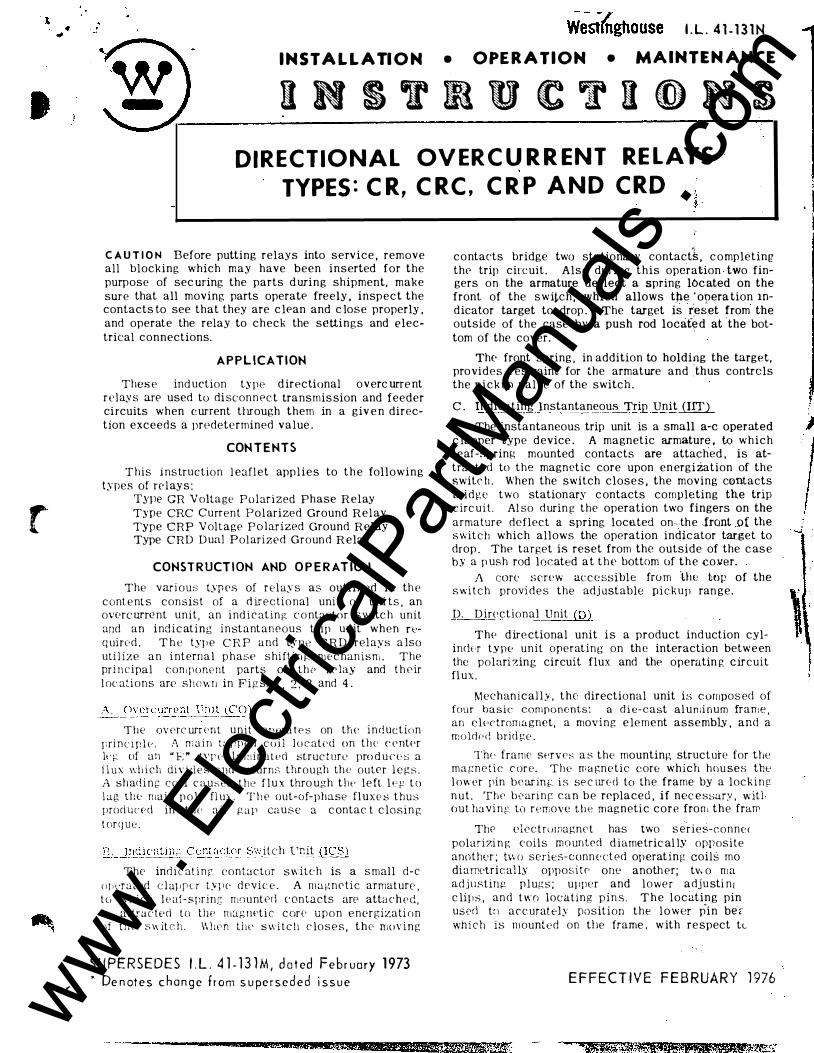
r
,
I . L . 4 1 - 1 3 1 N
I N STA L L A TI O N • OPE R A T I O N • M A I NTEN A NCE
I N S T R U C T I O N S DIRECTIONAL OV ERC U R R ENT RE LAYS
TYPES : C R, C RC , C R P AND C RD
C A U T I O N Before putting relays into service , remove all blocking which may have been inserted for the purpose of sec uring the parts d uring shipment. make sure that all moving parts operatf' freely . inspect the contacts to see that they are c lf'an and c lose properly . and operate the relay to check the settings and electrical connections.
A P P L ICATION
Thes e ind uction type d irectional overc urre nt relay s are used to di sconnec t transmis sion and feeder circuits when c urrent through them in a giv e n direction exceeds a prpdetermined value .
CON T E NTS
This i ns truction l eafl et app l i e s to t h e following types of re J ay s :
T.ype GR V olta ge Polarized Phase Relay Type CRC Current Po l arized Ground Relay Type CRP V oltage P o l arized Ground Relay Type CRD D ual Pol arized Ground R elay
CONST R UCT I ON AND O P E R AT ION
The var i ous typ es of r e l ay s as outlined in th e c onte nt s consist of a d irectio nal unit or uni ts . an overc urre nt u n i t , an i nd i c at i n g c o ntactnr s w itc h unit and an i nd i c ati ng i n stantaneous trip unit when req uirc· d . T h e typ e C R P and ty pe C R D relays a lso uti l i ze a n i nterna l p hase shift i n {'. m e c hanism . The pri n c i pal con,ponent parts of t h e re lay and t h e ir
l oc ations are shewn in Figs. 1 , 2 , 3 and 4 .
!� �· er�_llrrt'nt l' n i tj_5::'�0)
T h e oY erc urr Pnt u n i t opPra t e s on the i n d uction pri n c i p l v . A m a i n t : tpperl c o i l l o c at e d on t h e c entPr lq� of a n " E " t�T l· lamirwtPd struc t ure pro d u cT s a f l u x wh i ch diY i d e s and returns through th e outer l e g s . 1\ sh ad i n g c o i l c a u:-;es the f l u x thro ugh t h e l e ft l t· l-' t o l ag tllt· main p o l e fl ux . T h e out-uf-pha.se fl u xe s thus prod u c e d in the air gap cause a c ontac t c losin g t or q u e .
IL_lfl(!i.c.· atin;: _(:onta(_":_t.CJ.f:__§.l'. i t c h l'nit (ICS)
The ind i c at i n g contactor switch is a s mall d-e u J , vrated c l a! , f' LT type d ev ic e . A magnetic armature , t c, w h i c h l t> af- s pring n ,ount eci c ontacts are atta c h e d , i ;; attracted to the mag rwti c c or e u p o n e nergizati o n of t h (' s 11 it c h . \\ l :en t i l l' s w i t c h c lo s e s , t h e> mo\· i n g
S U P E R S E D E S I . L . 4 1 - 1 3 l M , d a t ed Feb r uary 1973 • De n ot e s c h a n g e f rom s u pe r s e d e d i s s u e
&W&WW4!&
contacts bridge two stationary contact1 , c o mpleting the trip circuit. Also during this operation two fingers on the armature deflect a spring loc ated on the front of the switch , which allows tP.e ' on era tion m� dicator target to drop . The target is r'eset from the outside of the case by a push rod locafe d at the bot-tom of the cover.
.
The front spring , in addition to holding the target, provides restraint for the armature and ·thus contrcls the p i c k up value of the switch .
·
C . Indicating Instantaneous Trip Unit J!ITl.. The instantaneous trip unit is a small a-c operated
c lapper type device . A magnetic armature , to which leaf-spring mounted contacts are attached , is attracted to the magnetic core upon en ergi zation of the switc h . When the switch close s , the moving contacts bri d ge two stationary c ontacts completing the trip c irc uit . Al so d urin g the operation two fingers on the armature deflect a spring loce.ted on -. .the front .ot: the switch which allows the operation indic ator t-arget to drop . The target is reset from the outside of the c as e b y a p ush rod located a t t h e bottom of t h e coYer.
/\ core �;crew ac c e ssi ble fro m Ute lnp of the switch provi d e s the adj ustable pickup ran ge.
D. D irectional llnit (D)
The d ire ctional unit i s a product ind uction cylincit-r t.vpe unit operating on th e interaction betwe en the polari zing circuit flux and the operatin g c ircuit fl ux.
Mechan i c al l y , the directional unit is c ompos ed of four basic components: a d i e-cast al uniinum frame an e lPctrornagnet, a moving e lement assembLY . and -� moldPd brid r:::e .
Tht· frame SPr v e s a s the mounting structure for the ma r::n c t i c c ore. The m a gnetic core which hou ses thP l ower pin bearillf:. is se c ur("d to the frame by a lock i n g
n u t . ThP bearin g c a n b e replaced . i f nec e ssary , w itl · out ha v i n e: to remove the magneti c core fron 1 the frarr
ThP electrurnagnet has two s e"r i e s-connec polarizi n g coils mounted d i ametric al ly opposite anott1er ; l\HJ series-conn e ct Pd op erat ing coils mo di a rretrical ls opposite one anoth er; tv. o n1a adjusting p l ug s ; upper and lower adju sti n t
c lip s , an d t w o locating p i n s . T h e locating pin usprl t�l a r c uratel.v posit i on the l o wer p-in ber whi c h is m ounted on tile frame , w ith re spect tc
E F FECT I V E F E B R UA R Y 1 976 www . El
ectric
alPar
tMan
uals
. com

www . El
ectric
alPar
tMan
uals
. com

t 1
N
r ·
l \
"' '
J
ll
. --- 7;" .. : -,� ., .. __ ij. ·
\ - ��-) j
,_ .. p- ! l ';;; F \ . , . ' I ......., 1
. I t - ... •\1 1. · "' .. �"'-.'_· r1 . . ' " 1 .--,., . .. ' f: '
1 l . • • C [ i._ ' " ' _ t. __ ---�\\1 :._ '
r �� : · ·. '-' T . · .
�-._, , . , .. -· • ../ -J . -r 1
i' · · , ,. ' r · ·
'
---i '?, 1
@___
r .....
f I f': t
�-
-� I / \ )
. t1 J ·--. I . ·- � ' �
• � 1 � d,) ; . . . - r , , '-./'·� • • -._ ·�-� --- I 1 ,!'!"-\ ("') . � ' l ... �-::._;.�_...,-� . : ,. ' . � . ..... . ,..,. . 1 ......... . ..,. ... ,_,
l 1 ,------ (j 4 .,
1) "" � .... -' - - . �4'.· � • ;. v � �-.- ' .. , -. �� '· ' ' ' ' ... . ,, ,_:......�: .1, (!'• -/ � i - r. �,. � t " ...<;\ I
:\;, .. J ' , i \ ! ' t ! \ i l ��l ' 1 I t
� -�. � - ' ......... �-
-I
:-· _---,.:· r.r--l � t. _r- ;.: 1 ' '
,..... '
l ' � \ • • t;- 1 ' ' � I
1 --..:' ,.;-
"""" ' t· ·� ' 1. ·;r�:l
A ; �--i ' ·: -; :'
' j
F i g . 1 Type C R R ,. /ny W i t l• out C n .< <> . 1 - D ire c t i ono . U n it
3 - l n d i c o t i n g C on -( 0 ). l - C v cr c urrcnf U n i t ( C O ) . f a c t or S w i t c h ( I C S ).
� .,
:il'-!· -
-�--�, ���.,(··· . . . '
: � :·
. ""-·.: ;·_ -�·- ' · . . ··· . "� .. · ,
/'/ "'' · · -/· ·....,.
�
·· ··-.
3 ) - · - - - l
Fig. 2. D irectional Unit, 1-Statlonary Contact. 2· Stationary Contact press ure spring, 3-Magnetlc
adiustlng p lugs. 4- Upper bearing screw. 5· Mov i ng elem:tnt assembly. 6-Sprlng adiuster
clamp, 7- C urre nt 13 1as Vane,
I '
�
' -4 \ ' -< "0 m V' ..... n ::tJ n ::tJ n n ::tJ "0 >z 0 n ::tJ 0 ::tJ m r >-< V'
-�.;n. 4 .QQ:p;;p;a .c z ;z:wr •• .; '* ... .....,. . ..... ·*1 u .e. « cx;R "' a . . waue,Q.e • r •• ;: ea ;a e:;. sa J U ¥41WW4#4Ztli#.M s .. JL!L 221 XL .. '
www . El
ectric
alPar
tMan
uals
. com

... .. .....
www . El
ectric
alPar
tMan
uals
. com

f'
T Y P E S C R , C RC, C R P AND C R D R E LAYS ____ �---- - - --
� !
I .L . 4 1 - 1 3 1 N
Fig. 3 . T ime O v erc urrent Un it ( Front V i ew). 1 - 1 ap B lo c k . 2- T ime D i o l . 3- Contro l Sp r ing A s semb ly. 4 - D i s c . 5-Stationary
Co n t a c t A s s embly. 6-il'.ognet i c P l u g s . 7- Perrr.onenf f.1ag n et .
Fi,� . 4 . I n di c at i n g l n stont a •, c cc u s Trir L1r i t ( 1 / T i .
3 www . El
ectric
alPar
tMan
uals
. com

www . El
ectric
alPar
tMan
uals
. com
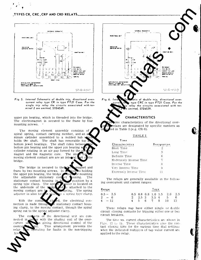
, '
_T Y P ES C R , C RC , CR P AHD CRD R ELAYS ______________________ _
•HII lfi.Allfl !UTMTM[GIIS f'OL M I TT .U _,.. n£ tiiEC!IM• . I T tlalALU tlASi
fROII:T Y ltlll
57 -D -4 ')4 7
F ig. 5 . I nternal S chematic o f do uble trip, di rection al o v e rcu rrent relay type CR in typ e F T 2 1 C ase. For t h e s i n g l e trip relay the c i r c u i t s a s so ci ated with term i nal 2 are o m i tted, 5704549.
upper pin bearin g , w h i c h i s thread e d into the bridge . The electroma gnet is s e c ured to the frame by four mounting scre w s .
T h e moving element assembly c o nsisLs of a spiral spri n g , contact carrying m e mber, and an aluminum cy·linder assembled to a molded hub which holds the shaft. The shaft has removable top and bottom j e w el bearin g s . The shaft ride s betwee n the bottom pin bearing and the upper p i n bearing with the cylinder rotating in an air gap formed by the electromagnet and the magnetic core . The stops for the moving element contact arm are an inte gral part of t h e bri d g e .
The bridge is s e c ured to the e l e ctromagnet and frame by two mounting scre w s . I n addition to hold i n g the upper p i n bearing , t h e brid g e i s used f o r mounti n g t h e adjustable stationary contact housin g . The stati onary contact housing is h e ld i n pos ition by a spring type c l amp. The spring adjuster i s located o n t h e und Prside of t h e bridge a n d is attached to t h e moving contact arm b y a spiral spring. The sprin g adj uster i s also h e l d i n pl a ce by a spring type c l a r : p .
With t h e contacts c lose d , the e l e ctric al connection is made througi·J the stationary c ontact housing c l amp, to t h e moving contac t , through the spiral spring o ut to the sprin g adj uster c lamp.
The contacts of th e directior:al ur:it are c onnected in series with the shad ing coil of the overc urr e r. t uni t , t h us g i v i n g d ir e ctional contro l of the overc urrent unit. T his arran g e ment pre vents t h e relay from operat ing for faults in t h e non-tri ppin g ji; ection.
4
W i lli I�T\1{ iiSTUTAIUMIS ,._.UITt &S ..,. h£ tttt,TIIIItt WIT C�Dt�T&c.u cus;:
F i g. 6 . I nt ernal S ch e m ati c of double trip, directio n al o vercurrent relay typ e C R C in typ e FT2 l C a se. Fo r th e sin g l e trip relay th e circuits a s so ci ated w i th term i n a l 2 are om itted, 5704539.
CHARACT E R ISTICS
T h e t i m e c h aracteristics o f t h e d irecti onal overc urrent relays are d e si gnat e d by spec ific num bers as indicated in Table I ( e . g. CR- 8).
TABLE I
T i m e
C h a r a c t e r i s t i c s Short Ti m e
Lon i' T i nw
D e fi n i t e Ti m e
Moderat ely Inverse Tim e J m· e r s e Ti m e
\"er:; I n v e r s e Ti m P
Exne m e l y ]n\· er s E T i r :: e
D e s i g n a t i o n
') 5 6
8 s
1 1
The relays are generally av ailable in ttw foll ov.
ing overc urrent unit c urrent ran g e s :
R a ng e T o p s 0 .5 - 2 . 5 0 .5 0. 6 0 . 8 1 . 0 1 . 5 2 . 0 2 . 5 2 6 2 2 . 5 3 3 . 5 4 5 6
4 1 2 4 5 6 7 8 1 0 1 :2
The s e relays ma_v have e ither s i n g l c- o r d c; ubl E· c ircuit closing contacts for trippi n g either one or t wo c ircuit bre ak ers .
The time v s . current c h aracter isti c s arc· s howr; i n Pi ;:: s . 1 3 t ll 1 8 . These c har:...cteri sti c s g i v e the contact closing time for th e various t i m e dial settin g s w hen thr- i n d i c ated m ultipl :-> s o f tap value c ur r e nt ar t: app lied t o t h e r e l ay .
www . El
ectric
alPar
tMan
uals
. com

"' ' '·
www . El
ectric
alPar
tMan
uals
. com
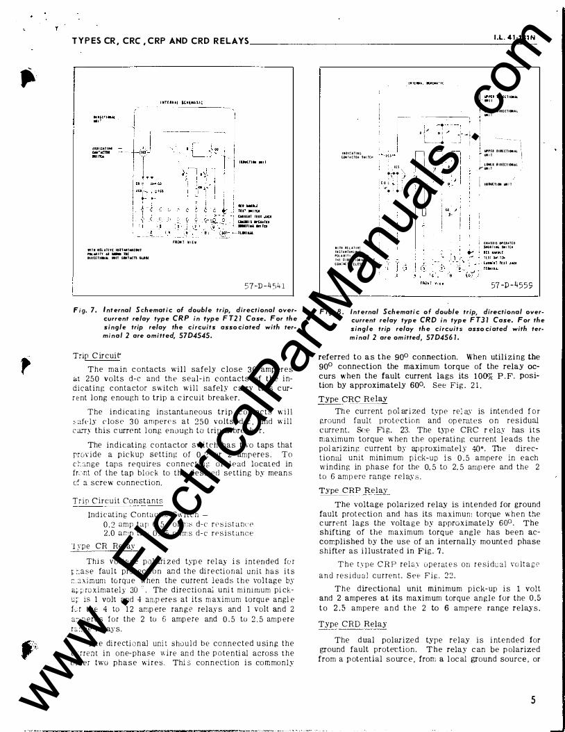
�·· TYPES CR, CRC ,CRP AND CRD REL AYS _____________________ u_._4_1 ·_13_1_N
Will ltlllU( IIITUT.UUIJ ..... M I Tl d - R(
tUUTI.AIL .It tiiTACn CUll
C' ¢ I ( ( • ·� �· 2
riOIT W l E W
57-D -4 54 1
Fig. 7. Int ernal S chemat i c of double trip, directional overcurrent relay type CRP in type F T2 1 Case. For the single trip relay the circuits asso ciated with terminal 2 are omitted, 5704545.
Trip C ir c ui t'
The m a i n c ontacts will safely c lo s e 3 0 amp ere s
at 2 5 0 volts d-e and th e s e al-in c ontacts of t h e i ndicat i n g c ontactor s witch w i l l safeLY c arry this c ur
r e nt l ong e nough to trip a c ircuit break er.
The i n d i c at i n g instantaneous trip c ont act s w i l l
!:c afdy c lose 3 0 ampere s a t 2 5 0 v o lts d-e . and w i ll c a:Ty th is c urre nt l ong e n o ugh to t ri p a bre akPr .
The i n d i c ating c o ntactor s w i t c h has two taps that prov ide a p ic k up setting of 0 . 2 or 2 amp ere s . To c �. ::m ge t aps re quires connecting o f l e ad locat ed in fr,�.nt of the tap block to the d e s ir e d setting by mean s
c: a scre w connection.
Trip Circuit Const ants
Ind i c ating Contactur Sl\ it c h -
0 . 2 amp tap 6 . 5 ohn:::; d-e r e ::; i st anu' 2.0 a r. ! p tal ' 0 . 1 5 oh m s d-e r e s i stance
'l ype CR Rel ay
Thi s voltage p o l ari z ed typ e r e l ay i s i n t en d ed fo r
t: :-.ase fau l t prot ecti o n an d the di r e cti o n al unit has i t s �. c.x im urn to r qLJ e when the current l e a d s t h e vol t ag e by
a;. �' ro ximately 30 ' . The directi o n al u ni t mi mrnum pi cku� is 1 volt and 4 an.p er e s at its m ax i m u m torqu e angl e
f·..:r the 4 to 1 2 amp ere ran g e rela,y s an d 1 volt and 2
a� p er e s for the 2 to 6 amp ere and 0 . 5 to 2 . 5 amp er e
r c. :; g e r el ay s . Th e di r ecti o n al uni t s ho u l d b e c o n n e c t ed u si n g t h e
c.: rrent i n o n e-phase w i r e an d t h e p o t e n ti al across t h e o : h er two p h a s e wi r e s . Thi s con n ection i s co m mo n l y
IIDICJ.Tllc;
UMilACTOQ S.l TCM
I I TM U L H I H
tltST.lliU[OUS
POl A I I T ! AS Si4011'11
TilE D l lii C T t tNI U \Ji l T CO*�AC T! CLOSE
'" .,... '\, : '- : J
: c.o 1 � : � ..,- ' i i . ' ·--'
- ��---; r - � l) j ..,i Jl ; � '· I 1 i "01 - t L.�. �___. · � j j
n ' I �
I I :I ·- · I . . , � ' !
-J '
I , I ; I � .
Ul ' ' f j. I I !
lo-{1 lllllCTIOU.l
.... ,
1 -·-·- - -- ' I ' L wru Otl£tTIOI.tl \1 I i,HI J l I ' . ' LOIIll •IIHl iOI.&l Y 1.11 1 l ,
i IIDU(;TL. III I l
'
J CIIAUtS O"[UT[D
SIIOI T I ... Sifi TCM
57 -P - 4 5 5 9
Fig. 8 . Internal Schemati c o f double trip, directional overcurrent relay type CRO in type F T3 1 Case. For the single trip relay the circuits asso ciated with term inal 2 are om itted, 570456 1 .
referred to a s t h e goo connection. When utilizing the
goo connection the maximum torque of the relay occurs when the fault current lags its l OOo/c P . F. posi
tion by approximately 600. See Fig . 2 1 .
Type CRC Relay
Th e current p ol ari ze d type rel ay is intend ed f o r ground fault p rotection and op e rate s o n r e s i dual c urre nt. See Fi g. 23. The typ e CRC r el ay has i ts m aximum torque w hen t h e operati ng current l eads the pol ari zin r: current by ap p roxi m ately 4{)•. Th e directional unit minimum p i ck-up i s 0 . 5 ampere in e ach winding in phase for the 0. 5 to 2. 5 amp ere and the 2
to 6 am p ere range r e l as s .
Type CRP Relay
The voltage polarized relay is intended for ground
fault prot ec ti o n and has its maximum torque w h e n the c urrent lags the volta g e by approximate ly 60° . The
shifting of the maximum torque angle has been ac
corr.plished by the use of an internally mo unt e d phase
shifter as i l lustrat e d in Fig . 7 . T h e t y p e C R P r e l a.y u p e r at e s o n r e si du a l v o lt a g e
a n d r e s i d u ::J l current. See F i g . 2 :.: .
T h e directional unit minimum p i c k- up i s 1 volt and 2 amperes at its maxi mum torque ang l e for the 0 . 5
t o 2 . 5 ampere a n d t h e 2 to 6 ampere range rela,)· s .
Type C R D Relay
The d ual polar i ze d type relay i s i ntended for ground fault prote-ctio n . T h e relay c an be p olarized
from a p otential somc e , from a l oc al ground source . or
5 www . El
ectric
alPar
tMan
uals
. com

www . El
ectric
alPar
tMan
uals
. com

T Y P E S C R , C R C, C R P AND C R D R E L AY S _
Tl:P type C H D w l ay uti l izes t h e d irect i o n a l tw it
. , f t ht · type CRC rE' ! as i n conjunction w !l h t h e ri in•ct ] ( )nal unit anrl phasP s h ift i n g Tl i P c h a n i s m of Lht • ty p p C H I' rl' by . ThP <lir<·ctional c o nta c t s arP c ·onnP d P rl
i n t 'ara l l t> l to t orquc-c ontrol a c o n · rn o n o v prc urren t u n i t . St·(· F i g . f\ .
T h · c urrent-po l ar i z e rl rl irt'ctional u ni t o f t h e ty pe ' ' H D rd a.v "nPr<l t P s on r e s id ual c urre nts w h i l e t h e
l •l · t;. T I•u tOt.l&UO� S•l TC� · -\!C)- ,
Ill i� li u ;.: I 'l i ll ] i Alol W. � I;> .. :; hH"" . , AS Sit�). 1 � 1
� 1 ., C 1 , ,_ , , � · I I C Olo • ...; 7 � C•u:i!.
f � -" . I I I •
_co
. t: ! - ) . ...... j
• • I ;u ·-
I II !.< I ( A l lll(.. l ll � l ,._ I UlO\JS ij�j l l
HL• �AIItlll HST S II I T ( n C U � k c � T l { S l JACI Ctl;.l S < l OP[UTU) 5�0� l 1 -" S•: H:H
F ig . 9. Internal S c h e m a t i c of s i n g l e trip dire ctional co n tro l
relay T y p e CR w i t h I n d i c at i n g I n s t ant aneous T r ip
Unit, in T yp e F T2 1 C a se.
IND ICAT iNG A - C CONTACT O R
S W I T C H
W : Tti R E L A T I V [ l r>i S T A N TA N E O!.'S
PO�._ A R I T Y A S S H CJ\11' .... T .., E
OIR ( C T I Q N A � UN1T C O "'TACTS c ._ O S E
nute n t i < i l fl < JL!r l / '·r i d irPC' l i . , n a l u n i t of tllP t.Y PP C f� l)
r e l a y o p P r a t e " u:; r!'s irl u a l vo l t ap: e and r e s i d u a l c ur
r e nt . S t · e F 1 r.: . 2 4 .
For t l i t · 0 . :'> t < • :z . :, a n t pert · a r.rj thl· 2 to (i a ! l :pPre
ran f.!, P rl'l <!.\ S , tr, . • n . i n i m U ! " p i c k - u p of tl� t · c urre nt
p< l i ari i':P rl uni t i O' 0 . :> a r1 pPr• · in PaC' l J v. ind i n e: i n-p huse
a nd t i J • · r r , i r l i n lJ ! ; , p i c k - up for tlw volta ;:.;t > p u ! a ri z•�rl
u n i t is 1 \' t i l t anrl 2 a n :pPrPs wit h t h e c urr• ·nt l a g g i n g v o l t a ;:.; • · I J� r;o".
IIDI�l�i•' ( O. ! i t l Di -·H S "' • n Ul
• I l l'! t!l & l l li !ll1U'¥.��� rou t 1 1 T t, � 1'1! DIHt!tGal.i. IIII I ; U. , &. : C l "'"Olt
·--
I II D U C I I OII UI I T
I II D I ( A l ! " G I II S T U TA.l(OU! Ioii i I
U tt M U Ol £
T U ; l • I T ( I' CUII!Jil 1 ( 3 1 J.t.CJ CIIAH i l Q r i l l H O SfiOic l i ll l . 1 T;:.K T f i N I U ...
Fig. 1 0. I n t e r n a l S c h e m at i c of s i ngle t r ip d i r e c t i o n a l c o n
trol relay T yp e C R C w i t h I n d i c at ing I n s t a nt a n e o u s
T r ip Un it, i n T yp e F T 2 1 C a s e .
-------- =-�-----
� - R E C T I O N .G. c
... ... · T
"- - 1' A N T A ,.'[ G J S ._ :-., , ;
* F i g . l O A . I n tern a l S c h em a t i c o f s i n g l e t r i p d : r c c t i o n a l co n t rol r e l ay T yp e C R with l n d. c c r ' n g I n s tantan eo u s Trip U n i t an d AC Sh u n t T ri p i n F T 2 1 C a s e.
6
t
'
• •
www . El
ectric
alPar
tMan
uals
. com

www . El
ectric
alPar
tMan
uals
. com

t
T Y P E S C R , C RC , C R P AND C R D R E L A Y S �------------ -- ---� ---------1 .-L_. _4_1 -_1_3_1 N_
,", \: P E R F
H M \ G E T A P -----
0 . 5
O . G
0 . 8
o . ::l , � _ :) 1 . 0
] . :,
2 . 0 • ) ' - - "
2 . 0 2 . 5 3 . ( 1
" G 3 . 5 -
- L O
: d J r: . o
4 . 0 5 . 0
C . O
4 1 � 7 . 0
8 . 0
l O . C
1 � . 0
COl'iT I 1\ UO C S
!\A 1 11\ L ; ( .1\ l\lPEH ES)
----- - -
--
0 . 9 1
0 . 9 G
1 . 1 8
1 . 37 1 . 9 5
2 . 24
2 . :-,o
3 . 1
· L O
1 . 4 4 . 8
5 . 2 � - (; G . O
- q ' . J 8 . 0
8 . 8
� - (; l fJ . .; 1 1 . 2
L' . O
E N E RGY R EQUIR EMENTS
C R - 2 , C R C - 2, C R P - 2, C R D - 2 O V E R C U R R E N T U N I T S
V O L T ,-\ \1 P E R E5 -1- ->-I ' ---��- ---�----- ---- - --------�----- - ---------
O N E SECOND
R A T l � G t ( t,MP EH ES)
--- -- ------- --·--
28
28
28
28
28
28
28
1 1 0
1 1 0
1 1 0
1 10
1 1 0
1 1 0
1 1 0
2�li 23() 230
230
2 3 0
2 3 0
230
PO WER
FACTOR ANGL E (�
5 8
5 7
5 3
50 40 3C
29
59
55
5 1
4 7 4 5
4 1
:n
65 50
47 < (' ·t el 4 3
31 3-i
AT
TAP V A L V E
CURR EJ\'1 -- - - - ----
4 . 8 4.9 5 . 0
5 . 3
6 . 2
7 . 2
7 . 9
5 . G 4
5. 1 3 5 . 3 7
5 . 5 3
5 . 7 2
5 . !40
G . 5 4
4 . 9 2 5 . 20
5 . 3 -!
5 . 53 5 . 8 f
(i .(i 1 . 00
A T 3 TnlES AT 10 T I M ES AT 20 T I �. :ES
T AP V ALll E TAP V AL L' E T AP V .A L L" E CURRENT C C H R FXf C L H H E :-.:-;·
------- - -
3 9 . G 256 790
3 9 . 8 270 8 5 1
4 2 . 7 3 0 8 1 0 � 4
4 5 . 4 3 4 8 1 2 20
5 4 . 4 4 35 1 74 0
G 5 . 4 5 80 :2�8(• 7 3 . C 7 00 2s :-,c,
3 8 . 7 2 C 2 S O C•
3 9 . 8 280 9 � (\
4 2 . 8 3 1 :2 J O CJc
4 2 . 8 3 29 1 1 ::0
4 6 . 0 3GO 1 2 l f
5 0 . 3 4 20 1 5 0 C '
5 4 . 9 4 7 4 1 8 fi( J
39. J 268 8 4 8
4 2 . 0 3 0 5 1 0 2LI
4 · L 1 330 1 1 ::c:
4 5 . 8 3G4 1 2((1 4 9 . 9 400 l 4 0f,
5 ;) _ 5 4'70 1 7 2(J G:! . 3 �<28 2()(;.;
1 id � ''.<ll C d f · !l : : • · (,_,r ,-, h ( ·'T! t l r; , ( · , u t f�. � - r t hu.n u n �· .-. t' r o n ::' rrd: !! • c o L � u · :� t t· d I ' TI t f. � i.' tl \ l < ( . 1 [ ! 'i , .i .• I T. f · u. � � ·r :- (.<) ;�.r(.; . ." • r t l "n d ! : . :. l� t .\ <;'t..lrl · u f ti.t r :. · · c n : .
7 www . El
ectric
alPar
tMan
uals
. com

www . El
ectric
alPar
tMan
uals
. com

f T Y P E S CR, C R C , C R P AND C R D R E L AY S _______________________ _
8
E H E RGY R E Q UI R EM E HTS
C R -5 C R C-5 C RP-5 C R D-5 CR-6 C R C-6, C R P -6, C R D-6 O V E R C U R R ENT U N I T S
ContlnWJt.;:-:. Ont- St·cuwi An,pere Haling H a t i n r. t Range Tap ( Arr•rPr<·" ) ( Ar •wn·s)
-, 0 . 5 2 . 7 8 8
( 0 . 6 3. 1 8 8
( 0 . 8 3 . 7 8 8
0 . 5 / 2 . 5 1 . 0 4 . 1 88
1 .5 5 . 7 8 8
2 . 0 r..8 88
2 . :) 7 . 7 88
2 8 230
2 . 5 H . H 230
3 9. 7 :..::-HJ 2/6 I 3 . 5 � 0 . 4 2:l0
5
4 I 5
( 8 ( 1 0
( 1 2
1 1 . 2 230
1 :2 . 5 J:l . 7
Pov. t-r At Fat:tor Tar Val m·
Angle (/, CurrPnl
69 3 . 9 2
6 8 3 . 96
67 3.96
GG 4 . 07
62 4 . 1 9
6 0 4 .30
5 8 4 .3 7
6 7 3 . 88
66 3. 90
64 3.93
63 4 .09
6 2 4 . 1 2
5 9
5 7
65 63 6 1 5 9
56 s:J 4 7
4 . 20
4 . 3 8
4 . 00
4 . 1 5
4 . 32
4. 35
4 .4 0
4 . f;[l
4 . 9:::
At 3 T i n r·>· Tal' \'a ! tH ·
CurrPnt
20.f
20.7
2 1
2 1 .4
23.2
24 . 9
2() . :2
2 1 2 l . f> 2 2 . 1
23 . 1
23 . S
24 . h
:!6 . :,
2 2 A
2 5 . :1
2 c . 4 o o ' ..... . . . . 30. 1
3S . �
A t 1 0 · r i rr ; � ·� '1 < t i · \ 'a! U•
Curr• ·Hl
l U:l l OG 1 1 4 1 ') ' 1 14 7 l f>F. I RO
1 1 0 1 1 H 1 .2G
1 3 6
1 4 4
Hi�!
l f U
C R - 7 , C P C - 7 , C R P - 7 & C R D - 7 O V E R C U R R E N T U N I T S
An�pPrP
Hung<' Tap
0 . 5
0 . 6
0 . 8
0 . 5 / 2 . 5 l . 0
( 1 . 5
( 2 . 0
( 2 . 5
2/C
2
2 . 5
3 3 . 5 4
5
( 4
( 5
4 . 1 :: 6
8
( 1 0
0 �
Contmuous Ratn;g
( Arr.pt·n•s}
3. 1
3. 7 4 . 1
5 . 7
G . 8 7. 7
8 . 8
9 . 7
I 0.4
1 1 . 2
1 2 . 5
1 3 . 7
l G I S . f1
1 9 . 3
:2 0 . 5 2 ::! . 5
2 ')
28
One &·e.md
Hating i (AOipPrt·S)
88
88
88
88
88
88
88
230
230
2:1 0
�30
230
230
230
4 f>O
4 fill
4 € 0
46(1
460 460
460
PO'W�.er Factor
Anglt· <!.-
68
67
66
64
6 1
58
56
66
63
63
62
61
59
58
64
6 1
60
5 8
55
5 1
4 6
.'\l Ta;� Valm
Cum·nt
3 . 88
3 . 9 3
3 .93
4 . 00
4 .08
4 . 24
4 . 3 8
4 . 06
4 .07
4 . 1 4
4 . 34
4 . �4
4 . 4 0
4 . 62
4 . 24
4 .3 0
4 . fi 2
4 . 69
4 . 8(\
5 . 20
5 . 4 0
At 3 Tire''"
Tal' ValUt:
CurrPnt
2 0 . 7
20.9
2 1 . 1
2 1 . 6
2 2 . 9
2 4 . 8
2 5 . 9
2 1 .3 2 1 . 8 2 2 . 5
23.4
2 3 . 8
2 5 . 2
2 7
2 2 . S
24 . 2
25 . 9 2 7 . 3
29 . 8
33
3 7 . 5
At 1 0 Tirr,e ;,
Tar1 Val ut·
CUIT!:"'nt
l o:l
I O'i
1 1 4
1 22
1 4 8
j 74
1 85
I l l 1 2(1 1 29 1 4 1
1 4 [1
1 63
1 83
t\t 20 '1 1 T1 ' ( · ;, T<1;· \'aluf·
Current
(i3{!
540
r: ( l ��
At 20 Tlrr . P S
Ta:-' \'&-l i..H-
Ct1!'7ent
278 288 3 20
356
459
552
640
306
36f.
4 13
4 -l 8
530
624
392
4 f>O
688
860
1 032
-+ J Ju r ."; u / capa c l t l c .::. for .s h<Jrt t t m � · . ., utht'r t h u. n ( !n t' ::. t: r: u n d rr.tJ) /,. c c u l c ulatc •i ( I n t h e b a s i .' of t im t• b e int int ·ers e l ) ; • r r •; · � · r t L nnul l t ; t h e s qu u -- c of t h e C L. .7t' n t .
www . El
ectric
alPar
tMan
uals
. com

www . El
ectric
alPar
tMan
uals
. com

TYPES CR, CRC, CRP AND CRD REL AYS _____________________ L_L ._4_1 ·_1 3_1 N E NERGY R EQUI R EMENTS
C R - 8 , C R C-8, C R P - 8 & C R D -8
CR-9 C R C - 9 C R P - 9 & C R D - 9 O V E R C U R R E N T U N I T S
VOLT AMPERES t t
Continuous One Second Power At At 3 Times At 10 Times At 20 Times Ampere Rating Rating t Factor Tap Value Tap Value Tap Value Tap Value
�Ra==n�g�e�-T�a�p--�(�A�m�pe�r�es�) --�(�A�m2pe�re�s�)��A�n�g�l e�¢�_ C�urr�e�n�t� __ �C�urr�e�n�t�--�C�WT��en�t�----�C�urr�e�n�t ---
0.5
0.6
0.8
0.5/2.5 1.0
1 . 5
2 . 0
2 . 5
2
2.5
3
2: 6 ( 3 . 5
( 4
4 / 1 2
AMPUlE
RA�GE
0 . 5 / 2 . 5
2/6
( 5
( 6
4
5
6
7
8
( 1 0
( 1 2
TAP
0 . 5
0 . 6
0 . 8
1 . 0
1 .5
2 . 0
2 . 5
.2 . 0
2 . 5
3 . 0
3.5 4 . 0
5 . 0
6 . 0
4 . 0
5 . 0
6 . 0
7 . 0
8 . 0
1 0 . Q
1 2 . 0
2 . 7
3. 1
3.7
4 . 1
5 . 7
6 . 8
7 . 7
8
8.8
9 . 7
1 0 . 4
1 1 . 2
1 2.5
13.7
16
1 8.8
19.3
20.8
22.5
25
28
C0!\11Nt10t'S
RATINCi
(AMPEHESJ ---------
1 . 7
1 .9
2 . 2
2. 5 3 . 0
3 . 5
3 . 8
7 . 0
7 . 8 8 . 3
9 . 0 1 0. 0
1 1 . 0
1 2 . 0
1 4
1 6
1 7
1 8
20
22
26
88
88
88
88
88
88
88
230
230
230
230
230
230
230
460
460
460
460
460
460
460
72
71
69
67
62
57
53
70
66
64
62
60
:>8
56
68
63
60
57
54
48
45
2 . 38
2 . 3 8
2 .4 0
2 . 4 2
2 . 5 1
2 . 6 5
2 . 74
2 . 3 8
2.40
2.42
2.48
2 . 53
2.64
2 . 75
2.38
2.46
2 . 54
2.62
2 . 73
3 . 00
3 .46
21
21
2 1 . 1
2 1 .2
22
2 3 . 5
24 . 8
2 1
21 . 1
2 1 . 5
22
22.7
24
25.2
2 1 . 3
2 1 . 8
2 2 . 6
2 3 . 6
24.8
27.8
3 1 . 4
CR-1 1, CRC-1 1
C R P . 1 1 & C R D- 1 1 O V E R CU R R E NT UNITS
mil-' SEC'OND HATING ·r
\ A M PJ-;H.ES)
56
56
56
56
56
56
56
230
230
230
230 230
230
230
460
460
460
460
460
460
460
POl\EH FACTO!!
ANGLE¢ 36
34
30
27
22
17
16
32
30
27
24 23
20
20
29
25
22
20
18
1 7
1 6
AT
TAP V A L U E
CUHHENT
0.72
0.75
0 . 8 1
0 . 8 9
1 . 1 3
1 .30
1 .4 8
0 . 7 3
0. 7 8
0 . 8 3
0.88 0 . 96
1 .07
1 . 2:1
0 79
0 . 8 9
1 . 02
1 . 1 0
L 23
1 . 32
1 . 8
A T 3 TIMbS
T A l ' V A Lt'F
Cli!UU'.I'T
6 .54
6.80
7.46
8 . 3 0
1 0 . 04
1 1 .95
1 3 .95
6 .30
7 .00
7 . 14
8 . 20 9 . 1 2
9 . 8 0
1 1 .3 4
7 . 0 S
8 . 00
9 . 1 8
1 0 . 00
1 1 . 1
1 4 . 9
1 6 . 3
132
134
142
150
1 70
200
228
136
142
149
157
164
180
198
146
1 58
1 72
190
207
248
292
AT 1 0 TIMES
TAP V ALliE
Cl'F:RENT
7 1 . 8
75.0
84.0
93 . 1
1 1 5 . 5
1 3 6 . 3
1 6 0 . 0
74 .0
78.5
84 .0
89.0 1 0 2 . 0
10ll .O
1 29 . 0
7 8 4
90.0
1 0 1 . 4
1 1 0.0
1 24 . 8
1 3 1 .6
1 8 0 . 0
350
365
4 00
440
530
675
BOO
360
395
430
470
500
580
660
420
480
550
620
700
850
1020
AT 20 TIMES
TAP VALUE
CURRE�T
250
2€7
298
330
4 1 1
502
6 1 0
264
285
309
340 3 7 2
430
504
296
3 4 0
378
;54
4 8 0
6 0 0
7 2 0
t Thermal capa cities for short times other than one s e cond may b e c al c ulated on the bas i s of time be ing invers e ly proportional to the s quare of the c urrent.
¢ Degre e s c urrent lags voltage at tap Falue c urrent.
tt Voltag e s taken with R e c t ox type voltmeter.
44£& -.QL . WM4 I I t£J&ZW§t£Lt.LW45UI JQ£.4§, t.W £)
9 www . El
ectric
alPar
tMan
uals
. com

www . El
ectric
alPar
tMan
uals
. com

T Y P E S CR I C : K I C R P A N D C R D R E LA Y S
1 0
R l · l a:v Range
Ty pe Amps
e n { 2-6 4 - 1 2 f 0 . 5- 2 . 5
C'RC '- 2-6 r j 0 . 5- 2 . 5
C R P '\ ! 2-f, '-
0 . 5- 2 . �) CJW .,'
2- t':
D I R E C T I O N AL U N I T P O L A R I Z I N G C I R C U I T B U R D E N
Rel ay Power Factor T ype Rating Vo lt Amperes 6 Angle 4!.,
CR
CRC
CRP
CRD Current
U nit
CRD Voltage
Unit
,___________ 1 3 2 *
Vol t s
230 • •
A nqw r c s
20 8 * * *
V ol t s
2 30 * *
A m p e r e s
20 8 * * *
\'o] ( :-; -- -- -
1 1 . 5 5 g0 Lag
1 .45 g0 Lag
1 1 . 2 2 g0 L e a d
1 .45 g0 Lag
1 1 . 2 2 g0 L e a d
- - - - ---
¢ Degre e s current leads or laf?.S voltage at 1 20 volts on voltage pola n ze d units and 5 amperes on cu"e n t polar i z e d unit s .
6 I oltag e s t a k e n wit h re ctox typ e Poltirr. e t c r - B urden of I oltage polar i z e d units taken at 1 20 t·olts - B ur
d en of c urrent polar i z e d units taken at 5 amp e r e s . * C o n t in uous rat ing .
• • On e s e c ond rat ing .
• • • 30 s e cond rat ing.
D I R E C T I O N A L U N I T O P E R A T I N G C I R C U I T B U R D E N
VOLT A!\�PEHES t t ------
At At 3 Time s At 1 0 Tinte::> Conti n uo u s One Second Power !l:i n i rr: u n: lli ini 111 un: M i n i m um
Rating Rating t Fad or Tap Val u e T a p Va lue Tap Val u e·
( Amperes ) ( Ampere s ) Angl e ¢ C urrent C urrent Current
1 0 23 0 34 . 5 0 . 4 4 · L OS 4 8 . 0 1 2 2 g o 2 5 . 0 0 . 53 5 . 0 5 9 . 2
2 3 0 4 4 . 0 0 . 0 3 3 0 . 3 0 3 . 3
2 3 0 4 2 . 5 O . S S 5 . 2 8 .') 8 . 0
1 0 2 3 0 3 4 . 5 0 . 03 0 . 23 2 . 8
1 0 2 3 0 34 . 5 0 . 4 4 · L OS 4 8 . 0
1 0 2 3 0 4 5 . 0 0 . 0 1 0 . 5 9 6 . 6
1 0 2 3 0 4 5 . 0 1 . 04 9 . 9 1 0 6 . 0
c!J / ) t 'f. .... t ' t ' S C U T r t u t lu;:, ,-, l l l i.. ! tl f!. C at t ap t uf u c c urre n t .
At 2 0 Titue s !l:i n i n t urr:
Tap V al ue
C urrent
1 8 2 . 0 23G . O
1 4 . 2 2 4 0 . 0
1 1 . 5
1 8 2 . 0
26 . 0
4 2 0 . 0
] lo r .F .'tw. l C U[H! C l ! L C .\ for \ h 1 ! r lr t i nif· 5 o t h (' r t h an one S (' C und nw ' be c a l : u / :; t e d on l /, t f,as l s of t i m t� lu · iug L·r. : r .r s c l; J • T t 'f ' ( � r t l url dl l \J thr S iji.H1 ... t ( l _f t h e c ur ren t .
· · I u l l d f!. t ' S t u f. t' n u L t h H. e c t uJ. l )pc y_ ·o l t m c · t e r.
www . El
ectric
alPar
tMan
uals
. com

www . El
ectric
alPar
tMan
uals
. com

T Y P E S C R , C R C , C R P A N D C R D R E L A Y S
tU[CttOIAI. 1.11 1 1 ·•
I I I P • a J I IHo
(�;o\( 1(11 ,...,," , .
I 1 I l l
CC : · -i t tS
i •
I I W C l i O II .- 1 1
!lVI C A i I � � lltSI .t.IIUIH.OUS Ult i T
I i I � RUJrj T 'I' l l •
Jr... - '
Cl!Ulll' TlST JACI ( M A S � I S Ol'iUT{(, S>tQii I I -� $111 1(11
H illol t M l ,
I lit ill H l l ' I Yl I I S l .t.k l U [ Cl U S I' Oul � ; 1 A� S..OWII Tl'li O t t : :. i t .)lo. .co. Ull l l CQIII U { ! l ClCSl
L�
F ig. 1 1 . Internal S c h e m at ic of single t r ip dire c t i o n a l c o n
trol r e l a y Type C R P with Indicat ing Instant aneous
Trip Unit, in T yp e F T 2 1 Case.
S E TT I NGS
A. Overc urre nt Unit (CO)
The over c urre nt unit sett i n g s can b e d <'f i n e c l
e J t her by t a p s ettings and time d i :. d p o s i t i o n o r tJy tap s etting and a sp e c i fie time of operuti o n at some
c urrent multiple of th e t ap s e t t i n g ( e . g . 4 tap s e tt i n g ,
2 tin ,e d i al position o r 4 tap sett i n g , 0 . 6 seconds at 6
tin ,c-s tap val ue c une nt ) .
To provide se lective circ uit breakcr operation . a
rni n i r::urr, c oordinat i n g time of 0.3 seconds p l u s break
c-r t i m L' is r e c omn,ended betw e e n the relay bein g S E't
and t h e relay s w i t h wh ic h coordination is to be
e ffected .
The c on n ector screw on th r· t err� i n al pl ate abovC' th e t iJT: e d i al makes conn ections to vari ou s tur n s on
the ont>rat i ng c o i l . By p l ac i n g the s crt> w i n the vari ous
t e rm i n i! pl ate h o l e s . the rel a_v w i l l re spond to m u l ti
pl e s o f tap val u e c u rrents in ac corrl a.n c e w i th U1 e vario u s ty p i c al t i me-current curves.
c a ut i on
Si n c e the tap b l o c k c o n n e c tor sere\\ c a rri l, s
operat ing c urre nt , b e sure that th ? screw i s turned
t i g h t . In order to avoid openint:. t h e c urr e n t tra n s
for mer c ircuits when changing tars und er l oad , con
n ect the spare tap scre w i n th e de si re d tap posi tion
before rem ov in g th e other tap s crew from th e ori ginal
I I I
I l L> I ( A l l · �
(!:*UCTOI S•rrv ,...._I t S ..
l l T K l tfl A T I H I I 5 T.I.Jt. l t.l { Oc �
1'0! 41i. t TI A: Soi:JWk TIH O l lt C 1 J (•�•' COtOl•U:C. CLJH
; ' , ,.
i 1
; � '· .
i
I .L . 4 1 - 1 3 1 N
U,...{l D i ii { C T itMU., "'" '
lOIIll O I I ( C l iOa lo.. oJ• r l
I IJPI'IIi O I I ! C T I Otu ... "'"
� ! I I O I C. .& l l l � j l t n u tufous u r ,
tuSl l � Of'[UTli SMOii T I I" S I I I C "
u c I!U.(Jl[
H�T s w r n 11
L_� �- -· -· --- ------------
Fig. 12. Internal S c he m at i c of s ingle t r ip directional cor.fr o l
r e l a y T ype C R D with Indicat ing I n s t ant aneo u s
Trip Un it, i n T yp e F T 3 1 Case.
tap P• Jsi t i o n . Insta m a ne o u s H P c l os i n g
Tll r f a c t c>ry a rl j u s t n : ent of t h e CO un i t c o n : ::. � : s n r " 1· i · ! · · s : 1 c r , n t c.w t fo i l [ > I': . \\'he r'· c irc ui t IJr('al\ e r > c 1 r J :c: in� '.': i 1 l b t · i n i t i at I 'd i m m e d i a t e l y after a t r i r =-:· t h f · CO G <Hl ! : tct , the t i m e of th e o p e n i n g of t h P c o n t ..:; :· : s shc •ul · l be a !'l i n i m u m . T h i s con d i tio n i s obtain e ·: : y ] o( )s r_. n i ng t h e stati onary con t act m o un t i n g s c:-o= ·-'· .
rH't u v i n g t h e c o n t ac t p l at e an d t h e n rep l ac i n � : :-: t> pl at e ll' i t h t h e bent f• n d resting a g ai n st the cor. : :.: :: �
st>r i n g .
Fr1 r • l r,u hl c t r i p r e l a y s , the u p p e r stationary con: c. : t i s a ' ! i u s t e r! s u c- b that t h e contact s p r i n g re st s s o L : : '
af.': t inst t h e b a c h st op . The low er stat i o nary cont a c : : s tlwn : l ' l i ust e ·i su l' 11 that both s t �1 t i onary contacts :: ..:;> c·
cDnL<·:· t s i rn u l tanl·ousl y with th e i r resr e c t i v P m o \- : :: ;
c n n t :1 c t .
B . l r : ri J c at i m· C Ci n t a c· t"r S\1 i t r-i 1 (!CS 1 -r � : ( · : J l :. s t · t t 1 : ; � r�__· qu l r t· d l 1 : 1 t i H-- lC'S L: n i t i s : : . ·, ·
:--:. e l � , , · t i 1 !: ·. J f t L t� 0 2 tu :2 0 :lJLp c· r e t al \ s t· t t i i J b T : . _ :-·
� e l :. i , i J i � : : , �1 d c l) \ C \ ) !H! E->Ct i n � t l i l ' l t-- ad l u c a t (< � _ : . fr · J ! J l 1 , j t L ll l � i Ll i \ ! c i\ t ( J t h t> d e :; � red S L· t t i n g lJy r ; ! l) :;. �::-u! t ! , t ' C : '• ! : ! i P C � i :1 f.: � C f P \\'
r • , _ . l nc ! ic at i n t: J r ; s t :i n l a n ·�:_u s �rri r ( liT )
Thr· c>rt · s e n · \'. :-r : u s t ht' ad jus ted t o the c1 l t.: c
J' i c k - u p dr ' s i red.
1 1 www . El
ectric
alPar
tMan
uals
. com

www . El
ectric
alPar
tMan
uals
. com
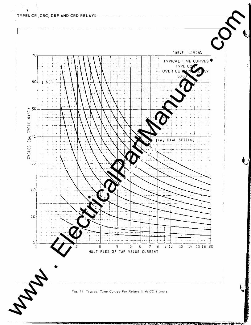
., T Y P E S C R , C R C, C R P AND C R D R E L A Y S ___ _
----���- ��- � ---- �
1 2
...u _.J u >u
T Y P I CA L T I M E CU R V E S
T Y P E C0-2
- OV E R C U R R E N T R E LA Y
50�60 HZ
J � c �, --------������r+������--�rt-��--�--��-4---------+----� <D I D I A L S E T T I N G Vl w _.J u >u
I I - • . . � - -
. . . . - - l/2 ------- -�-- --�
+ l
-� ·----· --- �j - - j -
1 0 1�c- : _
� � �� . I
- - - - _, - - - . . - - �- · - -- - ��33---+�==+=�== = � .
- - -· + - .. - . J - . (; '--f ----:-------"--------L-----L-'---"-----'----l-------'-L-.L__ ___ -'----
1 2 3 5 6 7 8 1 2 1 4 1 6 1 8 2 0 MU L T I P L E S O F T A P V A L U E CU R R E N T
Fig � 1 3 T)•p i c c l T i me C u r v e s Fo r R e i C )' S W r t h C 0 - 2 Lm ; ! s .
m
www . El
ectric
alPar
tMan
uals
. com

www . El
ectric
alPar
tMan
uals
. com

1 T Y P E S C R , C R C , C R P A N D C R D R E L A YS ________________________ ,..:.:. L:..:.._4_:_1 ·..:.:1 3:...:1.:..:...N
----
- --
--- ---
------- -
C U R V E l.i 1 8 2l.i 5 1 40�--����.--.----�--�--,--.--��������� - � . t - - - . . . t .
• - . . . f . • • . T Y P I CA L T I M E C U R V E S
T YP E C O 5
OV E R C U R R E NT R E LAY
50 60 HZ
1 20 �------��---+----�--r-�.--+-�-r�-r--+--+--� - � . ' . . . . . . . . l . .,. __ . . . . +• • • •
j • • • -
L : : : r � . . ; � . . : : : : : --- - L----t. _ ::__ �� � - . � - �·�� � ·-==: �·.:.:� -�t-----+---t---+----l . - ,- - . . .. . - - - --� - -- · 1. • : : : : : - . . : : · - . : : · : ; : : : . 1 . . i . . - . . . - � . .
1 0 0 '� ------��4---�--�---r--�-r--�r-�r--+--+--r�
r.n a ;z 0 u i..IJ ;j)
- ·- -·
-- +- - ·- · - · . ' j : � : : �� : : :
• �rl· · -�:- ::::�� :-
--:_
. t - -
I
2
I • • • + - • . • � . . --- - f .. - - � - - . . . . . . .. . . . . . . .. . . - . . .
- - .
- - o-- �- • - -
- I"-
--. . '
' -.
• . - I I
3
• · • · t . i ---- . : · .! - · . . . -- + · .,__ . . - - . . .
. - - - t · · - -
---- - +----- ---� -- -----+---+-t---1 • - - - +- - - - - -! . i - . . - - - t . • . . . j . . . . . L . . .
----- l- - - ---
. . . j . . . .
T .
. . . · t · · - - . .. . - - -
--- --
-- -
- � -
·- - -- - - - - - � -
7 8 ° 10 MU L T I P L E S O f T A P V A L U E CU R R E N T
- . ,__ I �; ; \ ::_
1 3 www . El
ectric
alPar
tMan
uals
. com

www . El
ectric
alPar
tMan
uals
. com

T Y P E S C R , C R C , C R P A N D C R D R E L A Y S
J) 0 z 8 \.._) u.J J)
1 4
l CU R V E � 1 82ij6 7 r-------�rr-<,��-----r,--�r-�---r--r,-.----.---.-�--�-r--------�----�
, � . : = :: ! - . : : : : �: 1 · : : : · - ·r : T Y P I C A L T I M E C U R V E S
I I
5
l,
..:0
2
j.-----�--1 i I i i I
I " L__ ��---v 1
---�------+ -l .
l - ·• . .. � . - . I
r c
. . . . J . . . . . . J . . . . T Y P E CO 6
I - ·-·--t·- - ··--· · ·· OV E R C U R R E N T R E LA Y
. . j �
� � j . 1 : : : · r · . . .
50 60 H Z
I . : - -1
I
1
I
5 6 7 8 9 10 12 14 1(, 18 2 0 M J L T I P L l S O F T A P V A L U E CU R R E N T
' i
- -� -- �-- . � - - ��- ____]
F 1 s; . ! 5 . Typ i ca l f J m t c ur v e s fo r re! u y s 1.-v d h CO· 6 Lt ri / 1 � .
www . El
ectric
alPar
tMan
uals
. com

www . El
ectric
alPar
tMan
uals
. com

,
T Y P E S C R , C R C , C R P A N D C R D R E L A Y S I . L . 4 1 � 1 3 1 N
r---���-��--�- ����� ��� I
C/J Cl z 0 u I.J.J C/J
T Y P I CA L T I M E CU R V ES
T Y P E C0 � 7 O V E R C U R R E N T R E LA Y
50-60 H Z
j I ���--�---� t�-�� -
. - - · -- � . i . ... . ' ' � j
-- ·--� 5 r-------����r--t--ir--�-f�--\t--��--t------1---,-1----1---�--4---��--------�'--------�
[ -- �� �--+ • �_r-- �-
[ -
-=
�
--"-
=-�
---=---'
: -c�
1 . :
�
� �:��� �� � -1 �:- : :� : -____ ..)._._ _____ _ _ _ f -
t��-==fu�:
f . · ; -- 112 ��§§El�+�t:�i:J�SS;;;;;;;;; t � ----------+--. �-t-- _ , � J '
- · � · t - -� - - - "" - ---- -� - - � -- - - � ' - -+--•--+ f . � --�����-- �> ' - � • ' -�� � - ·> · � - ---�-i -'- - -
G ' . . I --�j_------k-�--L--L-L---L---L--�-L--��--�-------2 3 5 6 7 8 9 10 1 2 1 4 16 18 20
M U L T I P L ES OF T AP V A L U E CU R R E N T
F1 9. 76 . Typ • co l l 1 m e c u r v e s fo r r el a y s w i th C0- 7 u n i ts .
1 5 www . El
ectric
alPar
tMan
uals
. com

www . El
ectric
alPar
tMan
uals
. com
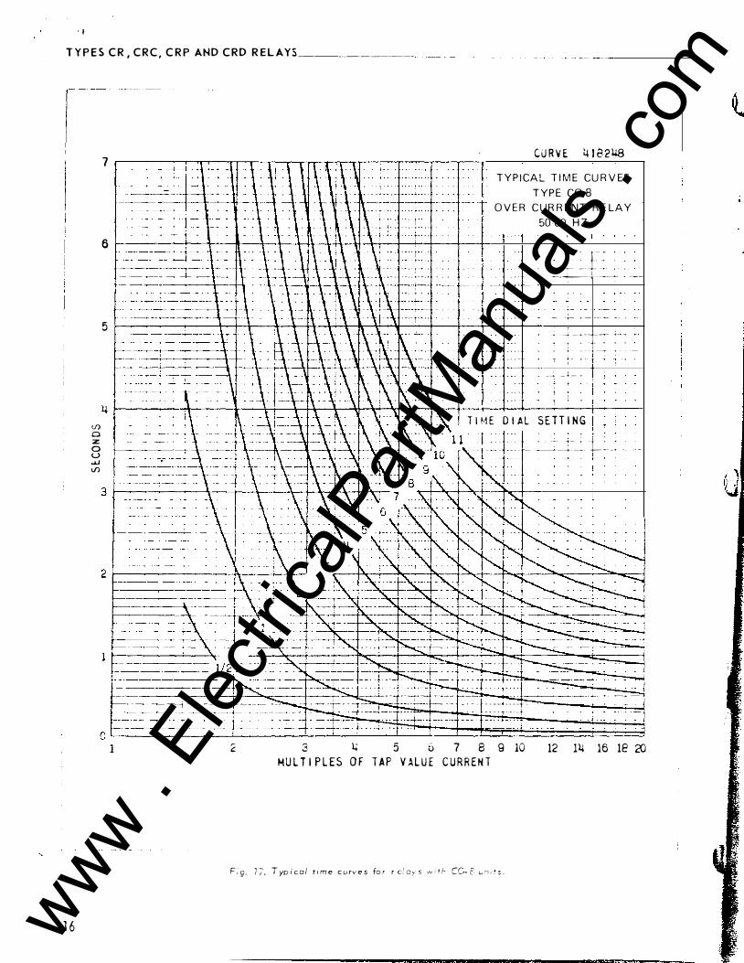
. I
T Y P E S C R , C R C , C R P AHD C R D R E L AY S �--�-�--------
1 6
(f) 0 :z 0 u � (f)
7
6
5
CU R V E 4 1 8 2 U8 T Y P I CA L T I M E CU R V ES
T Y P E C0�8
O V E R C U R R E N T R E LA Y
50 60 H Z
l�� . � -
-+-----�--�------ - ---
: --: �� -+-� :- : . 4- ---+ •
-� - l � -
� 1 . T I �� E D I A L S E T T I N G
� _ _ �-
�- -- �
�-'-- _·_ L:. _: - 1 '
- � -- � � � -t � - - - - �
�- �
-t
o L---------�------L----------L--�--I��j��f:j��f:::t=:�-�-��-���::�:r�;;�;;;;���� 1 2 3 l.+ 5 6 7 8 9 10 12 14 16 1E 2()
MU L T I P L ES O F T A P V AL U E C U R R E N T
F. g . 7 7 . T yp i c a l t i m e c u rv e s fo r r c.l o,-.• s ·,.., ; r t- CC- E G 'l i f s .
www . El
ectric
alPar
tMan
uals
. com

\ •
www . El
ectric
alPar
tMan
uals
. com

T Y P E S C R , C R C , C R P A N D C R D R E L A Y S l . l . 4 1 - 1 3 1 �.
U) 0
7
6
' ------ -+ �-t • �-+ �+
' +-
CURVE � 18:2ijQ T Y P I C A L T I M E C U R V E S
T Y P E C O 9 O V E R C U R R E N T R E LA Y
50 6 0 H Z
� �=��_:.�t� � �-------�i+ .. � . . �����-r����-+-t�-+--1--+�r-�������
� . -�� ..!. . c-·f· --'·
� ---- =j� f i
_... -t- --- -
\ · · · -- � - + -- · - � - � --. - - . - 4 -
� I -� 1/2 _
i L I
o�l· �· �7 ' ���� . . ���� 1 2 3 ),j !5 6 7 8 9 10 12 1� 16 18 20
M U L T I P L ES OF T AP V A L U E CU R R E N T
F i g . 18 . T yp i c o :' t i r.-: e c u r v e s f o r r e l c ,- � .-.- 1 1 h CO� � t. '�l r f s .
1 7 www . El
ectric
alPar
tMan
uals
. com

www . El
ectric
alPar
tMan
uals
. com

� Y P E S C R , C R C , C R P A ND C R D R E L A Y S _______ _
s � u "' "' "' -... " ....
2 .. ' 6 7 8 9 10 20 lO �0 100 --�-����������·���--
:g �--�-+-+-+--++-+-+--1f-+-+-+-+-+-+++--+l i- � �j 7 0 ---+-+-- f--� i � � � �---��+-+-+--++-+-���+-+-+++-+' -+--' � .. o �----�� ��+-+-+--++-+-��+-+-+-t+++-+1 �: -� . \ l \\\ ;
1 0 9 8 7
1 . 0 0 . 9 0 . 8 0 . 7 0. 6 0. 5 0 . � O . J
0 . 2
l-I . I
2
\ \ 1\ \
\
� ) 6 7 8 9 1 0
L-------------------------··
F i g. 7 S . Typ i ca l t J rn e C U rV' I? S fo r rf:: 1 U Y 5 ,·. � ; c--:. 7 7 u n l f s .
1 8
288 8655 T Y P I CA L T I M E C U R V ES
T Y P E C0 1 1
O V E R C U R R E NT R E L A Y
50 6 0 H Z
f l 14f D I U S l T T I M u
I i _j
. \ I '<i;-�
www . El
ectric
alPar
tMan
uals
. com

www . El
ectric
alPar
tMan
uals
. com

T Y P E S C R , C R C , C R P AND C R D R E LA Y S
I � USf OAS"Et' COU! C l l O � !ISTUO 0 � S O L I ll 011! ' 01 IELAf$ W I T � C . S-2. � lN•{I[ u•.c c�� .U!I co-� IJII i l L
Fig. 20. Diagram o f test connect ions of the over c ur rent un i t.
The namepl at e data will furnish the ac tual cur
rent ran g e th at m ay be obt ained fro m IIT unit.
D. Directional Unit ( D)
No setting is re quired.
I NSTALLATION
The relays shoul d be mounted on switchboard panels or their e q ui valent i n a location free from d irt , moisture, excessive vibratio n and h e at . Mount the rel ay v erti c ally by means of the two mounting st uds for the type FT projection case or by m e ans of the four mounting hole s on the flange for the semifl ush type FT case. Either of the studs or the mounting scre ws may be utilized for groundi n g the relay . The e l ectri cal connections m ay be m ad e directly to the terminals by m e ans of scre ws for ste el panel mounting or to terminal studs furnish ed with the relay for thick panel mounting. The terminal studs m a..v be easily removed or inserted by locking two nuts on the studs and then turning the proper nut with a wrench.
The external a- c con n e ct i o n s of t h e dir e c t i on'":
c . e r c u r r e n t r e l ay s are s h o w n in Fi g s . 2 1 t o 2-t.
ADJ USTM E N T S AND MA I N T E N A N C E
The proper adj ustments to insure correct operatio:of this relay have been made at the factory. Upon n·ceipt of the relay , no c ustomer adjustme nts , oth er than those c overed under "SETTINGs • , should be re quired_
For relay s which include an indi c a ti n g instantar.
e ous trip unit (liT) , th e junction of the inducti on and
i n di cati n g instantaneous trip coils i s brought out to
s v.i tc h jaw 11'3 . With thi s arran gement the overcurren t
uni ts can be tested separately.
,------------------
' J
, .. J;• II ( ,; . ,_,, "" POS.
I .L . 4 1 - 1 3 1 N
r [ : ; " � � A " ;OOi P . l . •C·r!.io 1� 1� 1 1>1' ; � ., "' I � L . : 0�
1 � !:. - I M , · I � � · ' • � c�·� u c r v • sr1 ;:r • • d�t:J.•L� .t � c � , , � , co.�� a c ;
' � . L r-. -' �
'--�-�------------------- - --
Fig. 2 1 . External S c h e m at i c of the type CR Relay for phose fault protect i o n ,
A cc eptance Check
The foll owing c h e c k is recomm end ed to i n s ure that the relay is in proper working ord er:
A. Overc urrent 'l'nit (CO)
The directional unit contac ts m ust be in the closed p o sition when c hecking the operati c,n of th e overcurrent unit .
1. Contact
a) By turni n g the time dial , move the moYing contacts until they d e fl e c t the stationary contact
to a position where the stati onary contact is resting against i t s bac k stop . The index mark l ocated on the m ovement fram e shou l d coincide
with the " 0 " m ark on the time dial . For doubl e
tri p r e l ay s , th e fol l o w on the stationary contacts shou l d be approxi mately 1/64 " .
b ) For rel ays identifi e d w i th a "T" , located at lower l eft of stationary c ontact block , the i n d e x
mark on t h e moveme nt frame w i l l coin c i d e wi th the "0" mark on th e time dial when the stationary c ontac t has moved through approx i m at e l y
one-ha l f of i t s normal defl ec t i o n . Th erefor e ,
w ith the stationary contact resting agai nst the
backstop, the i n d ex m ark i s offset to the right
1 9
JiiA&C&iL&J&ZL!L!!liiiJiliZL&Wi&£
www . El
ectric
alPar
tMan
uals
. com

www . El
ectric
alPar
tMan
uals
. com

TYP ES CR, CRC, CRP AND CRD REL AYS
i ,c� ,-===1 :;:!:. f + - -�
� " ·:· w '!' - �:-J l!l t • • -;r-v-r--rv-\ j{ - -+- .
�' !
Tr l 1 t ' l
T
l
1'\i�. " TIIIP MU!I _!.l_�!_I_C_�__!!I_�--���4111 "' "" 61A • ti i Rl � T IOU.l 0¥U.C!JJ(I<[IIl liKOI.III:l lEU' �16711 >t "
1C�
�bf;�� �6711 I T
" �� '
" -' . J,
Uio. • . i "'
POS.
10
T I PL C.r<P �!11 - lli liiCvliJClltl UMI T Of h P !. C�P " ���� • D I.HCT U)AAL Ull l l Of hPl CAP
)• - PQJbl C l lti:.IJ I ! llll.lAlt.<( r:� • I II � I C A I I I "' WII I AI.T""II �II TC.n
a - �lllUlK 1..-l H .. lA.ll l COIITA,CT l . · .:illlA�tc h: I P CO ll
l 82A 7 92
Fig. 22_ External Schemat i c of t h e type C R P Relay for gro�nd fa u lt protect i o n .
of th e "0 " m ark by approximately .020 " . The placeme nt of the vario u s time d i al positions in line with the index m ark will g i v e operating times as shown on the respective time-current curves. For doubl e trip relay s , the fol lo w on the stationary contacts should b e approximately 1/32".
2 . Minimum Trip Current - Set the time dial to position 6 . Alternately apply tap v al ue c urr e nt plus 3'r, and tap val ue c urrent minus 3o/c . The movin g c ontact should leave the backstop at tap val ue current plus 3o/c and should return to the backstop at tap val ue c urrent minus 3o/c .
3 . Time Curve - Table 2 shows the tim e c urve
c alibration points for the various types of relay s . With t h e t i m e d i al s e t t o t h e i n d i c at e d p o s iti o n , apply the c urrents specified by Tabl e 2 ( e , g . for the CR-8, 2 and -20 times tap v al ue c urrent) and measure the operating time o f the relay . The operatin g times should e qual those of Tabl e 2 p l us or minus 5 percent.
For type CR- 1 1 relay only, the 1 . 30 times tap value operating time from the number 6 time dial position is 54.9 ± 5o/c seconds. It is i mportant that the 1. 30 times tap value current be maintai n e d accurat elY. The maint aini ng of thi s c urrent a c c ur at ely is necessary
20
�e==·
�------------+�� ' 1-�----------------+�� '
�I f-1. I �-- --l :;�;�, t=_�-l �: Q• 6711 §1_11 6711
'l ' � � ·� ',.. 'k:-c-Yv- �:� I 5�· I
Tnj l 1 '
_!E� IlU�E � CIIU1
6711 · I H R E C J i r. A\.. OVlRCLJiiEIIT .. lr:OUIIV llH .. U
(IC;) :
·-1-6-��--J 1 c� ,: 67� !' l " rc
, - . ,1
·�=- ----''"-
TlPl CRC 6711 • O�UCI.IRIIllll l.l li i T Of TYPl Ck� co ���� - DIIHC I I O.... I. IJII I T Of rYPt CRC
!li - POWER C l llCU i r iiRU&.£11 I C S - l ll l:I I C A T I II oi COIIl.I.CTO., S•tTCii
.a - IU.UE� AUl l l l lil l COitlACT TC - iiE.U:i:il TII: I P t O l l.
l 8 2 A 7 9 C
Fig. 2 3 _ External S c h ema t ic of the type C R C R e l a y for ground fa ult protect ion.
hecause o f the steepness of the slope of the timecurrent c haracteristic ( F i g . l !:J ) . A 1% variation i n th e 1. 30 tim es tap value current ( inc! uding me asuring
instrument deviati on) will change the nominal operati ng time by appro x imately 4%.
B. Ind i c ating Contactor Switch (ICS) - C l o s e t h e main relay contacts and p as s s ufficient d-e c urrent through the trip c ircuit to c l o s e the contacts o f the IC S. This value of current s hould not be greater th an the partic ular ICS tap s etting being used . The in dic ator target should drop free ly .
The contact gap s ho uld b e approx imately . 0 ·17 �
betwee n t h e bri d g i ng moving contact and t h e adj ust
able stationary contacts. The bridging moving con
tact should touch both stationary contacts s i multan
e o usl y .
C - I n el i c � t i n i-__l_:l:-;t :_ll1_!:_arl_£C2_liC)_I��l_ l:n_i_t � I I}� ' T h • - C C> ! l' s c· r e \\ n , u s t h (· adj u s t (' cl t o t fl '' y � ) c ,
p i c k - u p c-u r r L n! d c si rr- d .
Th ( n ar. , '' l ' i a : o dat a \\'i l l fu rn i s h t h e- a ( ' t u :_il c u r ; - �: :
r an � E· t rw! m c:,Y k o b t ai n e d fro n , ! I T u n i t .
www . El
ectric
alPar
tMan
uals
. com

www . El
ectric
alPar
tMan
uals
. com

T Y P E S C R , C RC, C R P AHD C R D R E LAYS
• J
167111 � �1(• 1::s JG7-;--� I�� l---.J A' • 6711 -i·
/ " i" IL'-. qJ
IISU.ll ..II.Jiii" U S .I S S11.)r1 If
I"OTEITU.L 'OI..it i Z l l' I S 10�
uu:.
_ _![ W ! C t_�&t_K_ CIIIAIT 6711 - [HU\; i i iJit� O'l'[iCUkktiT iolo:;iVIo� �-:.LA�
1Jf'l CIP �� - 0Yilt\,lhi..lll 7 Ul / 1 Of HP£ tiL: ��i - L.OWU D�iEC T H iiiAl UI I T Of Tfll•t tiC ��t - Ufi'U: lllllCTIOIJ.O. "I l l Of TH'i ClD
i2 - P'OW£.1 CiUI.II T ULliU JU • t•;u.l th C41U.CTOC Srt TC..
• • JIU.&U I.;JJ.au.&� COITACT TC - iU.UU TIIP' Cl>ll..
'
i I
I
I .. ---'""'- 182.4791 1 F i g . 2_. Ex!ernol S c h emat i c of the type CRD Relay far
ground fault protect ion.
L>� Directi onal lJnit (D )
1 . Contact G ap - The gap betw een the stationary contacta-nd moving contact with the relay in a d eenergized position should b e approximat elv .020 • .
2 . Sensitivity - The respecti v e d irectional units should trip witt1 value of energization and phase angle relationshins as i ndicated i n Tabl e 3 .
3 . Spurious Torque Adjustments - There should be no spurio us closing torqu e s when the operating circ uits are energized per Table 4 with th e polarizing c irc uit s short-c irc uited for the voltage polari z Ec d urJts and open-circuited for th e c urrent polar
i zt>d ur.its .
cre <, ; ;,: e c- . A n : i n i n,�m: S ll i' i! P Sc t> d c h ec i'. o r. t h e r e l a y
�.y :·< t< : . :s tu c l o s e t !H· C l � n t �,:. c t ;; r r ;an t la l l y t ._.\ (.! .s s u r L' t n ;,t t !Y b r e a k e r t r i p s a n d t ll �:c t u rg e t d rc;p ::: . Tr, e: : re-
I f c. r; a d di t i unal t i n : e check i s d e s ired , pass s e C'-
I .L . 4 1 · 1 3 1 N
o n d a ry c u r r e n t t h ru uf',h t h e rel ay a n d c h e c k t l l l0 t i ru·
op e r at i on . It i s preferab l e to m a h e th i s at s e r e : c.. ti mE ·s p i c k - up c u r r e n t at an e x p e c t e d up e r at i n t: pc) : �. : for t h e par t i c u l ar app l i ca t i o n . For t h e . 5 tu 2 . 5 a r: . J.. e : crang r C0- 5 a n d C0-6 i n d u ction u n i t u se t h e a l t e r n a: i ". ,::
t e st c i rc ui t i n Fig . 20 a s t h e s e r e l ay s a r e affe c t ed t:: a di stort ed w av e for rr ; . Wi t h t h i s c o n n e cti o n t h E; 25 5 a m p n l' c u r rr· n t t r ::J n s fo r rn ers s h o u l d b e \HHk e d w e l l L t-] r J \1. t l r (; h rw P of t l J (' sat ur a t i o n ( i . e . , u s e 1 0 L 5 0 � :
b et t er ) .
A l l c ontacts should be p eriodicallY clean e d . A contact burnisher SII 1 8 2A 8 3 6 H 0 1 is recommended fer this purpose . The ust> of abrasive m aterial for c l e ar.
ing c ontacts i s not rec ommended , because of tht> d ar.
ger of e mbedding small particles i n t h e face of th e
U :o e t h t� fr,J l o wi n g proced u r e for c al i brat i n g tf. 1::
r el ay i f t h e r e l ay h a :-; b e e n t ak en apart for r ep ai r s u :
t h e ad.i u st rrJ e r ; t s h a n; b e e n d1 sturbed . T h i s p r o c e d u r tshould n o t be · u sed u n l es s i t i s app arent t h a t t �, e r el ay i s n o t i n prop e r w o r k i n g or de r . ( S ee " A c c e p :
a n c e C h ec k " ) .
A . Overc urrent Unit (CO )
1. Contact
a) By turning th e time dial , move the moving contacts until they d e fl ect the stationary contact to a position wh ere the stationary contact is resting ag ainst its backstop. Th e i nd ex marl-: located on the movement frame should coincide wi th th e "0" m ark on the time dial . For double trip rel a_y s , the follow on the stationary contac t s should be approximately 1/64 " .
b) For rel ays i dentified wi th a " T " . located at lower l eft of stati on ary contact block , the i nd e x m ark o n t h e movement frame w i l l coincide with th e "0" mark on the time d i al wh en the stationary c ontact has moved throu gh approxirnatdy one-hal f o f its normal defl ection . Th erefore. , with the stationary contact resting a gainst the back stop , th e index mark is offset to the right o f th e "0" mark by approximately . 0 20 " . The plac ement of th e v arious time di al positions in
line \\1 th th e index mark wil l gi ve op erating times as s hown on th e respecti ve tim e-curren t curves. For double trip rel ay s , the fol l o w on th e stationary cont acts should be approximately 1/32" 0
2. Mini rr. urr. Trip Curr e nt - The adj ustm ent of t h e
spring tension in setting th e minimum trip c urren: val ue of the rel a,.v is most conveniently made with t h e
2 1 www . El
ectric
alPar
tMan
uals
. com

www . El
ectric
alPar
tMan
uals
. com

·' T Y P E S C R , C R C , C R P A N D C R D R E L A Y S���
T A B L E 2 T I M E C U R V E C A L I B R A T I O N D AT A - 50 A N D 60 C Y C L E S F O R
O V E R C U R R E N T U N I T
P ermanent E l e c t ramagnet Magnet Ad j u s tment P l u g A d j u s tment
T i me Current Opera t i n g Current Opera t i ng R e l a y D i a l (Mu l t i p l e s o f T i m e (Mu l t i p l e s of T i me T yp e Pc s i t i on T a p V a l u e ) ( Secon d s ) Tap Va l ue ) (Secon ds )
2 (j 3 O . ;il 20 0 . 2 2
5 G 2 3 7 . 8 0 1 0 J.i . 30
l c G 2 2 . .:tr' :) I l . ! �l 7 (' _) 2 4 C) -. - ' 20 ] . 1 j
: 8 G 2 1 3 . 3:-l 20 ] . 1 1
I g 6 2 8. 8 1 20 I 0. 6 ;) I 1 1 6 2 1 ] . 2� :XI 0 . 2 -l _\
* 6 Fur 5 0 h<' r l /' \' u- 1 1 , :20 t i m, •s o p t · ra t i n r: T i rr"' Li n1 i t s a r • · 0 . 2 4 : 1 (fX - - 5':;
dar; •p i n g magn e t r r% o v e d .
\\ i t h the t i m e d i al s e t o n " 0 " , w i n d u p t h e s piral
spring by m e ans oi t h e s p r i n g adj uster u n t i l approxi
mately 6- 3 / 4 c o n v o l u t i o n s s h o w .
Set t h e r e l ay o n t llP rni n i m un: tap s e tt i ng , t h e time
d i a l to position 6 .
Adj ust the control spring t e n s i o n s o t h at t h f'
mov i n g contact w i l l l e avt! t h e bac k stop at tap v a l u t>
c urrent + l . CY;; and w il l r e t ur n to the back stop at ·tap v al ue c urre n t - l . OS .
3 . T i m e C urve Cal i brat i o n - Install the perman e n t ma g n e t .
AppLY t L e i n d i c at e d c urre nt p er Table 2 for t h e perman e nt m a g n e t adj ustment (e . g . CR- 8 , 2 t i m e s ta p val ue ) and measure t h e operat i n g t i rn P . Adj u st t h e perm a n e nt magrwt k e e p er u nt i l t li t · o pera t i n g t i m e· c orr t: s pund s to t h P ;-al ue of Tabh- 2 .
For typE> CI-:- 1 1 r e l ay o n l y , t h P 1 . 30 t i m e s t ap
v :l.l u • · oper atir;r t i � e from t h P n u m ber G t i m e rl i al p o s i t i , , :, i s 5 4 . 9 :c 5� s t- c n;, rl s . I t i s i r : p ortant th at t h e 1 . 30 t i r . • · !-i tap v a l u P c llr...r ; t be rr; a.i n t ai n Pd a c c ur at e l y . TL r r . :d n t a i n i n r o f t � ! i :- c u rr e nt a c c u ratP l:V i s n ( ' c e s s an h• ·cau s•' o f t h �· s: · · ·nm· ss o f t tJ , . �; ! o p p o f th e t i r: ; ,·C l l iT f!!1t c h a.r a c t c ri � � i c '1 F1 ;: . 1 � · , /\ 1 c� Y a.r i at in n i n t h � · 1 . :30 tir: es t ::l r • ·.- .: : ' 1 " c urr P n t ( i n cl ur!J n g rr; P a s u ri n i;
i n st rurr e n t rlc-\·Lt i ; ·�- · \'. i l l c h :m g e t h e n om i n al op erati n g
t i :· , by a ; T ru '. i r: a t · ly y; . I f t h e opera t i n g t i m e at 1 . 3
t i n r L' S tap v a l u e i s :kJt w i t h i n t h P s P l i m i ts . a m i nur a'i
j u strnent o f t h e c.:-.tr--' 1 s r r i n g w i l l gi ve t h e c o rr e c t oper :l t i n g t i m e wi tt, :> � ; [ any u n d u e· effect o n t h e m i n i m u m
p i c k - u p of th r reJ :i·, . T n i s c h ec k i s t o b e n: arle after
t � 1e ::; times t af• \' :: : � ,. a d j u s t m e n t h as be P n compl e t e ri .
:\; • p ly t lH· l T> · : i z · :ttl 'd c urr t: nt 1 w r T a b l e 2 for t tJ , . , . : . · c t r o m a g n d p l l L. a;l j us t m e n t ( P . g . C H- 8 , 20 t i nH· s
22
t a p v a l u e ) and m r · ast!fr ' t l ll' opl'rat i n ;.� t i m e . Adj u st t h e proper p l uf' unt i l tlw operat i n g t i m e c o rr p sponds to the v a l u(· in Tabl e 2. ( \\ ithdra w i n g t h p ! l' ft-h and
pl u.L� , fr( lnt v i e w , i ncTPasPs the o p erati n g t i m e and \\ it l ! r lral\ i n g the r i g ht - h and p l ug , front v i e w , d <· crr•as c s t h e t i n : P . ) I n adj u sti n g t h e p l u g s , o n e p i u g sl10ulci b e
SCfP\\ l'rl i n c u m p l etdy and ttJP other p l u g run i n or out u nt i l the proper o perat i n g t i m e has been obtain e d .
H e c tw c k the perman e n t m a g n et adju s tm e n t . If th e
opl:rat i n g t i me fur t h i s cal i brati o n p o i n t has c hanged ,
readjust t h e permanent magnet and then r e c h e c k the
e l PctromagnPt p l u g adj ustment.
D. l : : d i c at i ng Contactor S w i t c h - lJn i t (ICS}
C l o s p the m a i n r e l ay contact,; and pass s uffi c i e n t d-e c urnc i ! l t hroug h t ht· trip c ir c uit t o c l o s e thl· con
tacts c ,f t lH' ICS. This v al ue o f c urrent should L r· not
grE'atl ·r than thr · part i c u l ar ICS tap sf'tt i r J g tw i n r used .
ThE' i n'i i c a t m t ar g e t should drop fre l ' !_v .
:--., r · · \'. l.': l : i 1 · h i -..; t 1 d : u :-; t ;_! ! l l t · f ; · : : 1 . t L • t r � ; l ! · : r i ! · ' l ' · ! i · f ! : , i rJ ' · . ....:. t : J , J • i " · h u ; l \ :J J � · . ' I I � · t ; J ;
j : . . : : ' 1 f l , : � � ' • :- l J I ' U ; · j ' i ! ', 1 : l f ' • I ' J ·, .
l l . l l ir • · c· u " n :! ! l. n i t ( ]) ) 1 . T l: • · : : ! ' l ' E 'r p i n h r · a n ! l g shr, L: ) d t , , . S( 'fr · w • · c : ; J r , \I ! J
! J .i t i i t !wn i s at'Pro x i m at f ') y . 0 25 " c l l-ar:tn c r · i " · t '.\ ( · ( ·li
it and t l l \ ' t 1 1 ; . . ;f s h aft hr · ;u i n r; . T l i (· upp er p i ! : h•· a.r i n r
s h u u l d t h t · n i • r · s r · c ur d_y loc k e d i n pus i t i o n ·,•, i L h u, , .
www . El
ectric
alPar
tMan
uals
. com

i. ,
)
www . El
ectric
alPar
tMan
uals
. com

... TYPES CR, CRC, C R P AND CRD RELAYS _ ____________________ L_L_. 4_1_- 1_3_1 N
lock nut. The lower b earing position i s fi xed and
cannot be adj usted .
2 . The contact gap adjustment for the directional
unit i s mad e as fol l o w s :
W i t h t h e m o v i n g cont a c t in t he normal ly-open ed
p o s i t i o n , i . e . a g a i n s t t h e ri g ht s t op on bri d g e , sc rew
1 n t he 'it a t i on ary con t a c t unt i l bot h contact s just
c l " s e a s i ndi c at ed by a n eo n lamp in t h e con t a c t cir
c u i t . T h e n , screw the s t a t i o n ar y cont act a w ay from
t he m o vin g c on tact 3 . " 4 of a t urn . The cl amp holdi n g
the s t at i on ar y c o n t a c t lw u s i n g n e ed not be loos e n e d
I< > r t h e adj u s t m en t s i n c e t h e c l amp u t i l i z e s a spri ng
t y p e a c t i o n i n ho l d i ng t h e s t a t i o n ary c o n t a c t in
p : si t i o n .
The s et scre w i n the stati onary c ontacts has
been shop adj usted for opti mum follow and this ad
just ment should not be di sturbed.
The moving contact as sembly h as been factory
adjusted for low contact bounce performance an d
should not b e chang ed.
3. The sen sitivity adjustment is made by varyin g t h e tension of the spir al sprin g attached to the moving
element assembly . The spring is adjusted by placing
a screwdriver or similar tool into one of th e n otches located Qn the periphery of the spri n g adjuster and
rotating it. The spring adjuster is located on the underside of the brid g e and is held in place by a spring type clamp that does not have to be loosened prior to making the necessary adj ustments .
The spring is to be adjusted such that the con
tacts will c lose as indicated by a neon lamp in the cont act circuit when energized w ith the required c ur
rent and voltage as shown in Table 3 . This table
indicates that the spring can be adj usted w hen the
.phase angle relationship between the operating c ircuit
and the polarizing circ uit i s at the maxi m um torque angle or when the c ircuit relationship has the o perating and polarizing circuits in phas e . It is recom
mended that a single phase (in phase relationship) set-up be used as a matter of ease and c onvenience.
4. The magnetic plugs are used to rev e rse any unwanted spurious torques that may be present when the relay is energized on current alone .
The reversing of the spurious torques is ac
complis hed by using the adjusting plugs in th e fol
lowing manner:
a) Voltage circuit terminals on th e voltage polar
ized relays (CR , CRP and CRD voltage polarized
unit) are short-circuited.
b) The polarizing eire uit of the c urrent polarized
rel ays (CRC and CRD c urrent polarized unit) are open-circuited .
Upon completion of either M a " or " b " , current i s applied t o t h e operating circuit terminals a s per Table 4 .
P l u g adj u stment i s then made per tabl e 4 such
that the spurious torques are reversed . The plugs are
held in position by upper and lower plug c l ips. These
c lips need not be di sturbed in any manner wh en mak
ing the necessary adjustment.
The magnetic plug adjustment may be utilized to positively close the contacts on c urrent alone . This
may b e d esired on some installations in order to insure that the relay will always trip the breaker on
zero potential .
RENEWAL PARTS Repair work c an be done most satisfactorily at the
factory. However, interchangeable p arts c.an b e furnished to the customers who are e quipped for d oin g repair work . When ordering parts , always give th E
comp lete nameplate data.
lf. T A B L E 3 D I R E C T I O NA L U N I T S E N S I T I V I T Y
R e i o y T ype
en
C H ! '
C E D 1 \" u l ta g t t · r ' 1 r 1
c n c C H ! l 1 C t;rw n �
l " n l t )
R a t i n g
4 - 1 2
2-C 4 - 1 2
2-fi
__ T______ -- ----- -- -- ------- --- - --- - -- ---- --- -V a l u e s for M i n . P i ck - Up -V 1--�-�
---1- - - -- - -- -��Pha
.
s e Ang l e R e l a t i on s h i p o t s Amperes
- --� ----- -- - - ----
1 2 . 0 1 1e ad l n g V b� 3 0° • -- -- - �- -- - - - -- - -- -i 1 2 . 3 I J n - p h a s e \� i t h v
- -r -- 1-- - - - - - 4-(;------- -I I eactwr.: v t.v 3 o0 - -
1 -= -i -- . +- - -
4 ,
- --I
_i n-12_����� i t h \'___ _ ____ _
2 . 0 I la�c; g i n g V by 6 0°
· 1 --- ------ - - - - - - ---------- - ----- � 4 . 0 I in-phase with V i . O :-: . o
0 . 5
] . (1
I la n.: i ! : ,.: V !Jy (i O i :
l n- p h a s t·
7 h ( · ('IU' rf.!.. ; :::: u. l l url (!lJ • ;n z i t u · ., t lf ( ' Hij ' l. / liUi l rd : : u · s ut t h e r( /,J .., tc rnn n u. f.\ . �!tn . l rrJt.u:. lor (i U. C (I.f;,L' L ' . �
f ' , , ,.t I 1J \ " r 1 J f ( ,/ ,:}_ -+ ( ,• ' , f : . i (/ tf ·/ \ ;} 1 '( ,f t
O:!IU4i¥11i4i§&IACU
2 3 www . El
ectric
alPar
tMan
uals
. com

�. )
. ...
www . El
ectric
alPar
tMan
uals
. com

TYPES CR, CRC, CRP AND CRD RELAYS ______________________ _
24
Relay Rat ing
0 . 5 to :?..5
2 to 6
4 to 1 2
0 . 5 to 2 . 5
2 to 6
4 to 1 2
Current Amperes
4 0
80
4 0
80
T A B L E 4 D I R E CT IO NAL U N IT C A L I B R A T I O N
Both Pl ugs In Cond i t i on
Spurious Torque In Contact Closing Direction (Left Front View)
Spurious Torque In Contact Opening Direction ( Right Front View) ( Contacts remain open)
Ad j ustment
Right (Front-View) Plug Screwed Out Until Spurious Torque is Reversed
Left (Front View) Plug Screwed Out Until Spurious Torque is in Contact Closing Direction, Then the plug is screwed in until spurious torque is reversed.
www . El
ectric
alPar
tMan
uals
. com

..
'
www . El
ectric
alPar
tMan
uals
. com