Directional Control Valves - Vektek · 2020-02-17 · Directional Control Valves Manual Seat Valve...
7
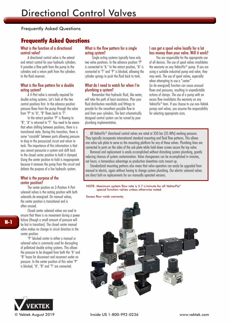
© Vektek August 2019 Inside US 1-800-992-0236 www.vektek.com What is the function of a directional control valve? A directional control valve is the extend and retract control for your hydraulic cylinders. It provides a flow path from the pump to the cylinders and a return path from the cylinders to the fluid reservoir. What is the flow pattern for a double acting system? A 4-Port valve is normally required for double acting systems. Let’s look at the two control positions first. In the advance position pressure flows from the pump through the valve from "P" to "A", "B" flows back to "T". In the retract position "P" is flowing to "B", "A" is returned to "T". You need to be aware that when shifting between positions, there is a transitional state. During this transition, there is some "crosstalk" between ports allowing pressure to drop in the pressurized circuit and return to tank. The importance of this information is that you cannot pressurize a system and shift back to the closed center position to hold it clamped. Using the center position to hold is inappropriate because it removes the pump from the circuit and defeats the purpose of a live hydraulic system. What is the purpose of the center position? The center position on 3-Position 4-Port solenoid valves is the resting position with both solenoids de-energized. On manual valves, the center position is transitional and is often unused. Closed center solenoid valves are used to ensure that there is no movement during a power failure (though a small amount of pressure will be lost in transition). The closed center manual valve makes no change in circuit direction in the center position. "P" blocked center in either a manual or solenoid valve is commonly used for decoupling of palletized double acting systems. This allows the pressure to be dropped from both the "A" and "B" hoses for disconnect and reconnect under no pressure. In the center position of this valve "P" is blocked, "A", "B" and "T" are connected. What is the flow pattern for a single acting system? Single acting systems typically have only two valve positions. In the advance position "P" is connected to "A." In the retract position, "A" is connected to "T" and "P" is blocked, allowing the cylinder springs to push the fluid back to tank. What do I need to watch for when I’m plumbing a system? Remember that hydraulic fluid, like water, will take the path of least resistance. Plan your fluid distribution manifolds and fittings to provide for the smoothest possible flow to and from your cylinders. The best schematically designed control system can be ruined by poor plumbing implementation. I can get a spool valve locally for a lot less money than your valve. Will it work? You are responsible for the appropriate use of all devices. The use of spool valves invalidates the warranty on any VektorFlo ® pump. If you are using a suitable industrial pump and valve, they may work. The use of spool valves, especially when attempting to use a “center” (or de-energized) function can cause unusual flows and pressures, resulting in unpredictable actions of clamps. The use of a pump with an excess flow invalidates the warranty on any VektorFlo ® item. If you choose to use non-Vektek pumps and valves, you assume the responsibility for selecting appropriate sizes. All VektorFlo ® directional control valves are rated at 350 bar (35 MPa) working pressure. They typically incorporate international standard mounting and fluid flow patterns. This allows one valve sub-plate to serve as the mounting platform for any of these valves. Plumbing lines are connected to ports on the sides of the sub-plate while hold-down screws secure the top valve. Removal and replacement is easily accomplished without disturbing system plumbing, greatly reducing chances of system contamination. Valve changeovers can be accomplished in minutes, not hours: a tremendous advantage as production downtime costs mount up. Standardized mounting patterns also mean that valve operation can easily be upgraded from manual to electric, again without having to change system plumbing. Our electric solenoid valves are direct bolt-on replacements for our manually operated versions. Frequently Asked Questions NOTE: Maximum system flow rate is 5.7 L/minute for all VektorFlo ® special function valves unless otherwise noted. Excess flow voids warranty. Directional Control Valves Frequently Asked Questions N-1
Transcript of Directional Control Valves - Vektek · 2020-02-17 · Directional Control Valves Manual Seat Valve...
© Vektek August 2019 Inside US 1-800-992-0236 www.vektek.com
What is the function of a directional control valve? A directional control valve is the extend and retract control for your hydraulic cylinders. It provides a flow path from the pump to the cylinders and a return path from the cylinders to the fluid reservoir.
What is the flow pattern for a double acting system? A 4-Port valve is normally required for double acting systems. Let’s look at the two control positions first. In the advance position pressure flows from the pump through the valve from "P" to "A", "B" flows back to "T". In the retract position "P" is flowing to "B", "A" is returned to "T". You need to be aware that when shifting between po si tions, there is a transitional state. During this transition, there is some "crosstalk" between ports al low ing pressure to drop in the pres sur ized circuit and return to tank. The importance of this information is that you cannot pres sur ize a system and shift back to the closed center position to hold it clamped. Using the center position to hold is inappropriate because it removes the pump from the circuit and defeats the purpose of a live hy drau lic system.
What is the purpose of the center position? The center position on 3-Position 4-Port solenoid valves is the resting position with both solenoids de-energized. On manual valves, the center position is transitional and is often unused. Closed center solenoid valves are used to ensure that there is no movement during a power failure (though a small amount of pressure will be lost in transition). The closed center manual valve makes no change in circuit direction in the center position. "P" blocked center in either a manual or solenoid valve is commonly used for decoupling of palletized double acting systems. This allows the pressure to be dropped from both the "A" and "B" hoses for disconnect and reconnect under no pressure. In the center position of this valve "P" is blocked, "A", "B" and "T" are connected.
What is the flow pattern for a single acting system? Single acting systems typically have only two valve positions. In the advance position "P" is connected to "A." In the retract position, "A" is connected to "T" and "P" is blocked, allowing the cylinder springs to push the fluid back to tank.
What do I need to watch for when I’m plumbing a system? Remember that hydraulic fluid, like water, will take the path of least re sis tance. Plan your fluid distribution manifolds and fittings to provide for the smoothest possible flow to and from your cylinders. The best schematically designed control system can be ruined by poor plumbing im ple men ta tion.
I can get a spool valve locally for a lot less money than your valve. Will it work? You are responsible for the appropriate use of all devices. The use of spool valves invalidates the warranty on any VektorFlo® pump. If you are using a suitable industrial pump and valve, they may work. The use of spool valves, especially when attempting to use a “center” (or de-energized) function can cause unusual flows and pressures, resulting in unpredictable actions of clamps. The use of a pump with an excess flow invalidates the warranty on any VektorFlo® item. If you choose to use non-Vektek pumps and valves, you assume the responsibility for selecting appropriate sizes.
All VektorFlo® directional control valves are rated at 350 bar (35 MPa) working pressure. They typically incorporate international standard mounting and fluid flow pat terns. This allows one valve sub-plate to serve as the mounting platform for any of these valves. Plumbing lines are connected to ports on the sides of the sub-plate while hold-down screws secure the top valve.
Removal and replacement is easily ac com plished without disturbing system plumbing, greatly reducing chances of system contamination. Valve change overs can be accomplished in minutes, not hours: a tremendous advantage as production downtime costs mount up.
Standardized mounting patterns also mean that valve operation can easily be upgraded from manual to electric, again without having to change system plumb ing. Our electric solenoid valves are direct bolt-on replacements for our manually operated versions.
Frequently Asked Questions
NOTE: Maximum system flow rate is 5.7 L/minute for all VektorFlo® special function valves unless otherwise noted.
Excess flow voids warranty.
Directional Control Valves
Frequently Asked Questions
N-1

© Vektek August 2019Outside US+1-913-365-1045www.vektek.com
Single and Double ActingMaximum Operating Pressure 500 bar (50 MPa).Minimum Operating Pressure 10 bar (1 MPa).CETOP 3 adaptation.
SpecificationsModel No.
Nominal Size Type Nominal
FlowWeight
(g)
47-0301-55 6 Seat Valve 12 L/m 444
Model No. 47-0301-55 2-Position, 3-Port
Seat Valve - Manually Operated - For Single Acting cylinders
Model No. 47-0301-55
ATP
Model No. 47-0331-55 2-Position, 3-Port
Seat Valve - Solenoid Operated - For Single Acting cylinders - 24 VDC
Model No. 47-0341-55 2-Position, 3-Port
Seat Valve - Pneumatically Operated - For Single Acting cylinders
Model No. 47-0341-55
ATP
ATP
Model No. 47-0331-55
CETOP Sub-plate
Model No.47-0941-10
SpecificationsModel No.
Nominal Size Type Nominal
FlowWeight
(g)
47-0331-55 6 Seat Valve 12 L/m 740
SpecificationsModel No.
Nominal Size Type Nominal
FlowWeight
(g)
47-0341-55 6 Seat Valve 12 L/m 459
85.9102
44
25.4
35
8
8
11 11
51
25.4
22
44
4.1 4.1 Locating Hole
9.1
32.9
ILMV709400 REV D
B
A
P
T
G1/4 Tank Port
Pressure Port G1/4Auxiliary "A" Port(With G1/8 Plug)
Auxiliary "B" Port(With G1/8 Plug)
M5 X 12 deep (4X) For CETOP 3 Valve Mounting Pattern
Mounting Holes for M5 Socket Head Cap Screwfour places
"A" PortG1/8
"B" PortG1/8
Directional Control Valves
CETOP 3 Valves
N-2

© Vektek August 2019 Inside US 1-800-992-0236 www.vektek.com
15
8
TA
P
40
22
30 ±0,1 5
35 ±
0,15
25,5
17,5
45
9,5
Ø40 8113
M6 6
84
Model No. 47-1112-53
TP
A
Seat Valve 2-Position 3-Port Valve Solenoids work with or without a shift lever and are designed and checked to VDE 0580. Seat valve has a manual emergency actuator. A check valve is incorporated in channel "P". Seat valve has complete hydraulic pressure compensation and negative switching. Position of installation is optional.
Diagram:
2-Position 3-Port seat valve nom. size 5Characteristic ∆p=f(Q)
Q( /min)
Insert check valve
2 4 6 8 10 120
∆ p (bar)
10
20
30
40
50
A T
P A
NOTE: The flow direction must be the direction of the arrow according to the symbol. The position of installation is optional.
Model No. 47-1112-52
APT
Specifications
Model No. Nominal Size Valve Type Connection
Maximum Operating Pressure(bar) (MPa)
Nominal Flow
(l/min.)
Viscosity(c St)
Ambient Temp.
(C°)
47-1112-525
Normally Opened/Normally Closed
Manifold500 bar
(50 MPa)12 10-500
-40 to +80°47-1112-53
Actuating Element
Model No. VDC P(VA)
Switch Time(ms)
RelativeDuty Cycle
(%)
Switching (Freq/ Hr.)
CodeClass
Weight(g)
47-1112-5224 20
100 on50 off
100(to 35° C)
2000 IP 54 71047-1112-53
Directional Control Valves
Seat Valve 2-Position 3-Port
N-3

© Vektek August 2019Outside US+1-913-365-1045www.vektek.com
Model No. 47-0301-56
Port AUnused
Model No. 47-0301-57
9
SpecificationsModel No.
NominalSize
Valve Type Connection
MaximumOper. Pressure
(bar) (MPa)
NominalFlow(l/min.)
Viscosity(cSt)
47-0301-565 Seat Manifold
500 bar (50 MPa)
12 10-50047-0301-57
Model No.
AmbientTemp.
(C°)
ActuationType
SwitchingTorque(N cm)
Switching Stroke(mm)
SwitchingAngle
Weight(g)
47-0301-56 -40 to +80°
ControlKnob
63 3.5 90° 40047-0301-57
Manual 2-Position2-Port Seat Valve
Manual 2-Position3-Port Seat Valve Oil channel can be closed or open by means of a manual 2-Position 2-Port seat valve. Manual 2-Position 3-Port seat valve allows determination of oil flow direction. Seat valve has complete hydraulic pressure compensation and negative switching. Position of installation is optional.
NOTE: The flow direction must be the direction of the arrow accordingto the symbol. The position ofinstallation is optional.
Model No. 47-0301-57Model No. 47-0301-56
T
P
50
A
T
P
10 30±0,1
2215
8
35±
0,1
25,5 9,5
17,5
5
1119
45
20
30M6 x 10Depth
G1/4
A
A
SpecificationsModel No. Dimensions Connection Weight
(g)
47-0941-57 50 x 45 x 30 3 x G 1/4 450
For pipe connection in combination with:
- 3/2-way Seat Valve Model No. 47-1112-52 - 2/2-way Manual Seat Valve Model No. 47-0301-56 - 3/2-way Manual Seat Valve Model No. 47-0301-57
Directional Control Valves
Manual Seat Valve 2-Position 2-Port / 2-Position 3-Port
N-4

© Vektek August 2019 Inside US 1-800-992-0236 www.vektek.com
88.9
50.8 Sq
40.5
32.5
50.8
31
77.5
24.4
31 32.5
40.5
50.8 Sq
90.7
12.7
7.9 MaximumPanel Thickness
90 90
ILMV711105 REV A
Long optional handle shipped with all models.
CETOP 3 Mount Panel Mount
Shown in pressurized position
M5 MountingScrews Included
G1/4 Port Locations Shown In Top View
Lock NutIncluded
M5 Threaded Mounting Holes
B PortPlugged
P
A
T
Manual Control Valve: 2-Position, 3-PortFor use with single acting systems.Heat treated rotor and poppets provide positive fluid control. Detented internal rotor.All valves ship with short and long handles. Handle orientation can be adjusted in 45° increments.
NOTE: Maximum system flow rate is 5.7 L/m for all VektorFlo® metric valves unless otherwise noted.
Excess flow voids warranty.
Model No. Valve Configuration47-1142-21 CETOP 3 Mount47-1142-25 Panel Mount
88.9
50.8 Sq
40.5
32.5
50.8
31
77.5
24.4
31 32.5
40.5
50.8 Sq
90.7
12.7
7.9 MaximumPanel Thickness
90 90
ILMV711105 REV A
Long optional handle shipped with all models.
CETOP 3 Mount Panel Mount
Shown in pressurized position
M5 MountingScrews Included
G1/4 Port Locations Shown In Top View
Lock NutIncluded
M5 Threaded Mounting Holes
B PortPlugged
P
A
T
CETOP 3 Mounted PressureCheck Valve Sandwich PlateP-Check Valve prevents pressure drop in the pressure line of the valve.Valve plate is installed between the valve and the supply manifold.
Model No. Contents47-0347-41 Contains P-Check Valve Plate
50.8 Sq
32.531
40.5
9.65
P-Check
ILMV711107 REV A
Directional Control Valves
Manual Seat Valve 2-Position 3-Port
N-5

© Vektek August 2019Outside US+1-913-365-1045www.vektek.com
Manual Control Valve: 3-Position, 4-PortThese valves can be used to control a double acting workholding system. (May also be used to control single acting systems)Rotary handle motion uses a rotary bearing.Heat treated rotor and poppets are spring and pressure loaded against each other to provide positive fluid control for hundreds of thousands of cycles.All valves ship with short and long handles.Handle orientation can be adjusted in 45° increments.
SpecificationsModel No.
Valve Configuration
Fluid Flow Maximum
Tank Port Pressure
CETOP 3 Mount43-1147-21 Closed Center
5.7 l/min17 Bar
(1.7 MPa)43-1147-41 P-Blocked CenterPanel Mount
43-1347-21 Closed Center5.7 l/min
17 Bar (1.7 MPa)43-1347-41 P-Blocked Center
50.8 Sq
40.5
31
32.5
50.8
50.8 Sq40.5
31 32.5
7.9 MaximumPanel Thickness
12.7
90.7
88.9
77.5
24.4
45
45
45
45
ILMV711403 REV A
43-1147-21 Closed Center 41-1147-41 P-Blocked Center
Handle shown in A-side position.
Long optional handle shipped with all models.
CETOP 3 Mount Panel Mount
43-1347-21 Closed Center 43-1347-41 P-Blocked Center
M5 Cap ScrewsIncluded
Lock NutIncluded
G1/4 Port Locations Shown In Top View
M5 Threaded Mounting Holes
A
T
B
P
Directional Control Valves
Manual Seat Valve 3 Position 4-Port
N-6
© Vektek August 2019 Inside US 1-800-992-0236 www.vektek.com
Solenoid
Model No. FunctionValve
Connector Part No.
SolenoidVoltage
Power Usage(watts)
DutyRating
47-1123-21 Closed Center 85-5342-91 24 VDC 27.6100%
47-1123-40 P-Blocked Center 85-5342-91 24 VDC 27.6
231 50.8
50.847.8
ILMV471100 REV D
PBC CC
DIN 43650Solenoid ValveConnectors- Included
CETOP 3 Mounting Pattern
SolenoidModel No.
FunctionReplacement
Valve ConnectorSolenoidVoltage
Power Consumption
Duty Rating
Maximum Cycle Rate
47-1112-54Normally
Open85-5342-91 24VDC 28 Watts
100% 2000/hr47-1112-13
Normally Open
87-1123-00 115VAC* 29 Watts
47-1115-03Normally Closed
85-5342-91 24VDC 28 Watts
47-1115-05Normally Closed
87-1123-00 115VAC* 29 Watts
45
13745 21.8
ILMV711103 REV E
includedValve Connector
DIN 43 650Design A
NC NO
CETOP 3Mounting Pattern
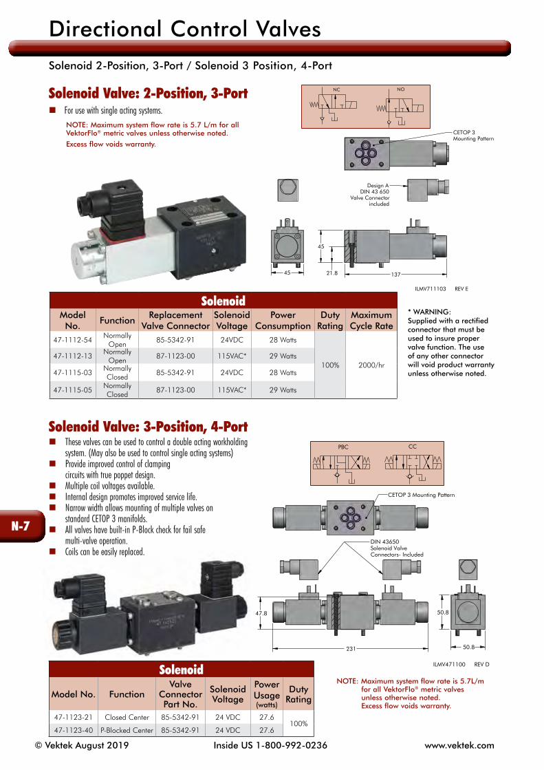
Solenoid Valve: 2-Position, 3-Port For use with single acting systems. NOTE: Maximum system flow rate is 5.7 L/m for all VektorFlo® metric valves unless otherwise noted.
Excess flow voids warranty.
Solenoid Valve: 3-Position, 4-Port These valves can be used to control a double acting workholding system. (May also be used to control single acting systems) Provide improved control of clamping circuits with true poppet design. Multiple coil voltages available. Internal design promotes improved service life. Narrow width allows mounting of multiple valves on standard CETOP 3 manifolds. All valves have built-in P-Block check for fail safe multi-valve operation. Coils can be easily replaced.
* WARNING: Supplied with a rectified connector that must be used to insure proper valve function. The use of any other connector will void product warranty unless otherwise noted.
NOTE: Maximum system flow rate is 5.7L/m for all VektorFlo® metric valves unless otherwise noted. Excess flow voids warranty.
Directional Con trol Valves
Solenoid 2-Position, 3-Port / Solenoid 3 Position, 4-Port
N-7