Direction Changes of Isothermal Remanent Magnetization...
8
Pertanika 13(2), 247-254 (1990) Direction Changes of Isothermal Remanent Magnetization (IRM) for Multidomain Particles Produced by Stationary Alternating Field Demagnetization SAHAT SADIKUN and AlAN STEPHENSON* Department of Earth Service, UKM Sabah Campus Locked Bag 62, 88996 Kota Kinabalu, Sabah Key words: Direction changes, IRM, multidomain particles, stationary alternating field demagnetization. ABSTRAK Pengawamagnetan ulang-alik (a.j) satu-paksi dan tiga-paksi ke atas remanen pemagnetan isoterma (IRM) untuk zarah magnetit beraneka saiz telah dikaji. Pengawamagnetan satu-paksi he atas IRM mengalihkan vektor remanen tegak lurus terhadap paksi a.f sejurus sebelum semua remanen dinyahkan. Peralihan sudut apabila dilakarkan terhadap pecahan remanen dinyahkan, tidak menunjukkan sebarang pergantungan terhadap saiz zarah. Pengawamagnetan tiga-paksi terhadap IRM pula menghasilkan perubahan arah secara progresif ABSTRACT Single-axis and three-axis alternating field (a.j) demagnetizations of isothermal remanent magnetization (IRM) for magnetitie particles of various sizes have been investigated. Single-axis demagnetization of IRM shifted the remanent vector perpendicular to the a.faxis just before the remanence was completely removed. The angular shift when plotted against the fraction of remanence lost, did not show any dependence on particle size. Three-axis demagnetization of IRM produced progressive direction changes. INTRODUCTION The angle between the a.f. axis and the mag- netization vector is important in the stationary aJ. demagnetization process. Its role signi- ficance was investigated as early as 1937 by Schmidlin (1937). Stephenson (1983) showed theoretical and experimental results of single- axis demagnetization at various angles to the remanence i.e. isothermal remanent mag- netization (IRM) and anhysteretic remenent magnetization (ARM) or thermo-remanent magnetization (TRM). The demagnetization was most effective when the a.f. was parallel to the remanence vector and least effective when the a.f. was perpendicular to the remanence vector. In other cases, it produced an angular shift and the remanence moved to a direction normal to the a.f. axis. Stephenson also (1983) showed theoretical and experimental results of three-axis demagnetization of ARM and IRM. Three-axis demagnetization of ARM did not produce any angular shift. Three-axis demagnetization of IRM caused the remanence vector to move towards the nearest direction which made an angle of cos- 1 (1/;/3) with the a.f. axes unless the initial IRM was in the plane of two of the a.f. axes, in which case it moved to an orientation which lay at 45° to the two a.f. axes defining that plane. * Department of Geophysics, School of Physics, University of Newcastle upon Tyne, Newcastle upon Tyne, NE2 7RU, United Kingdom.
Transcript of Direction Changes of Isothermal Remanent Magnetization...
Pertanika 13(2), 247-254 (1990)
Direction Changes of Isothermal Remanent Magnetization (IRM)for Multidomain Particles Produced by Stationary
Alternating Field Demagnetization
SAHAT SADIKUN and AlAN STEPHENSON*
Department of Earth Service, UKM Sabah Campus Locked Bag62, 88996 Kota Kinabalu, Sabah
Key words: Direction changes, IRM, multidomain particles, stationary alternating fielddemagnetization.
ABSTRAK
Pengawamagnetan ulang-alik (a.j) satu-paksi dan tiga-paksi ke atas remanen pemagnetan isoterma (IRM)untuk zarah magnetit beraneka saiz telah dikaji. Pengawamagnetan satu-paksi he atas IRM mengalihkanvektor remanen tegak lurus terhadap paksi a.f sejurus sebelum semua remanen dinyahkan. Peralihansudut apabila dilakarkan terhadap pecahan remanen dinyahkan, tidak menunjukkan sebarang pergantunganterhadap saiz zarah. Pengawamagnetan tiga-paksi terhadap IRM pula menghasilkan perubahan arah secaraprogresif
ABSTRACT
Single-axis and three-axis alternating field (a.j) demagnetizations of isothermal remanent magnetization(IRM) for magnetitie particles of various sizes have been investigated. Single-axis demagnetization of IRMshifted the remanent vector perpendicular to the a.faxis just before the remanence was completely removed.The angular shift when plotted against the fraction of remanence lost, did not show any dependence onparticle size. Three-axis demagnetization of IRM produced progressive direction changes.
INTRODUCTION
The angle between the a.f. axis and the magnetization vector is important in the stationaryaJ. demagnetization process. Its role significance was investigated as early as 1937 bySchmidlin (1937). Stephenson (1983) showedtheoretical and experimental results of singleaxis demagnetization at various angles to theremanence i.e. isothermal remanent magnetization (IRM) and anhysteretic remenentmagnetization (ARM) or thermo-remanentmagnetization (TRM). The demagnetizationwas most effective when the a.f. was parallelto the remanence vector and least effectivewhen the a.f. was perpendicular to the
remanence vector. In other cases, it producedan angular shift and the remanence moved toa direction normal to the a.f. axis.
Stephenson also (1983) showed theoreticaland experimental results of three-axisdemagnetization of ARM and IRM. Three-axisdemagnetization of ARM did not produce anyangular shift. Three-axis demagnetization ofIRM caused the remanence vector to movetowards the nearest direction which made anangle of cos-1 (1/;/3) with the a.f. axes unlessthe initial IRM was in the plane of two of thea.f. axes, in which case it moved to anorientation which lay at 45° to the two a.f. axesdefining that plane.
* Department of Geophysics, School of Physics, University of Newcastle upon Tyne, Newcastle upon Tyne, NE2 7RU, UnitedKingdom.
SAHAT SADIKUN AND AlAN STEPHENSO
MATERIALS AND METHODS
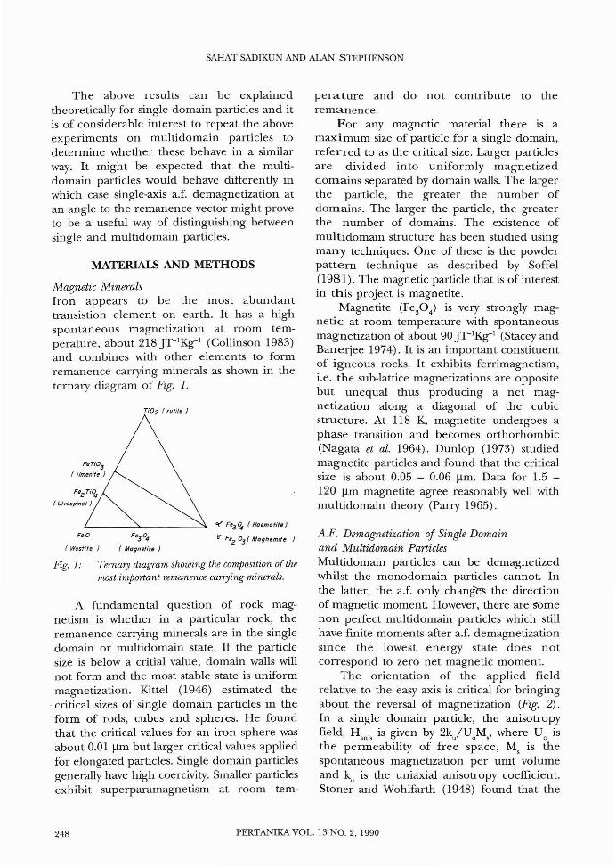
Fig. 1: 'Fernary diagram showing the composition of themost important remanence carrying minerals.
Magnetic MineralsIron appears to be the most abundanttransistion element on earth. It has a highspontaneous magnetization at room temperature, about 218 Jr-1Kg-l (Collinson 1983)and combines with other elements to formremanence carrying minerals as shown in theternary diagram of Fig. 1.
perature and do not contribute to theremanence.
For any magnetic material there is amaximum size of particle for a single domain,referred to as the critical size. Larger particlesare divided in to uniformly magnetizeddomains separated by domain walls. The largerthe particle, the greater the number ofdomains. The larger the particle, the greaterthe number of domains. The existence ofmultidomain structure has been studied usingmany techniques. One of these is the powderpattern technique as described by Soffel(1981). The magnetic particle that is of interestin this project is magnetite.
Magnetite (Fe30 4 ) is very strongly magnetic at room temperature with spontaneousmagnetization of about 90 JT-1Kg-l (Stacey andBanerjee 1974). It is an important constituentof igneous rocks. It exhibits ferrimagnetism,i.e. the sub-lattice magnetizations are oppositebut unequal thus producing a net magnetization along a diagonal of the cubicstructure. At 118 K, magnetite undergoes aphase transition and becomes orthorhombic(Nagata et al. 1964). Dunlop (1973) studiedmagnetite particles and found that the criticalsize is about 0.05 - 0.06 11m. Data for 1.5 120 11m magnetite agree reasonably well withmultidomain theory (Parry 1965).
A.F. Demagnetization of Single Domainand Multidomain ParticlesMultidomain particles can be demagnetizedwhilst the monodomain particles cannot. Inthe latter, the a.f. only changes the directionof magnetic moment. However, there are somenon perfect multidomain particles which stillhave finite moments after a.f. demagnetizationsince the lowest energy state does notcorrespond to zero net magnetic moment.
The orientation of the applied fieldrelative to the easy axis is critical for bringingabout the reversal of magnetization (Fig. 2) .In a single domain particle, the anisotropyfield, H anis is given by 2kjUoMs' where U 0 isthe permeability of free space, Ms is thespontaneous magnetization per unit volumeand kn is the uniaxial anisotropy coefficient.Stoner and Wohlfarth (1948) found that the
ct' Fe3 q, (Haemofife)
r FeZ OJ (Moghe mite )
Ti02 (rutile)
Fe3
04
( Magnetite )
FeO
(Wustite )
The above results can be explainedtheoretically for single domain particles and itis of considerable interest to repeat the aboveexperiments on multidomain particles todetermine whether these behave in a similarway. It might be expected that the multidomain particles would behave differently inwhich case single-axis a.f. demagnetization atan angle to the remanence vector might proveto be a useful way of distinguishing betweensingle and multidomain particles.
A fundamental question of rock magnetism is whether in a particular rock, theremanence carrying minerals are in the singledomain or multidomain state. If the particlesize is below a critial value, domain walls willnot form and the most stable state is uniformmagnetization. Kittel (1946) estimated the
. critical sizes of single domain particles in theform of rods, cubes and spheres. He foundthat the critical values for an iron sphere wasabout 0.01 11m but larger critical values appliedfor elongated particles. Single domain particlesgenerally have high coercivity. Smaller particlesexhibit superparamagnetism at room tem-
248 PERTANlKA VOL. 13 NO.2, 1990
DIRECTION CHANGES OF IRM FOR MULTIDOMAIN PARTICLES
.... Easy axis
H
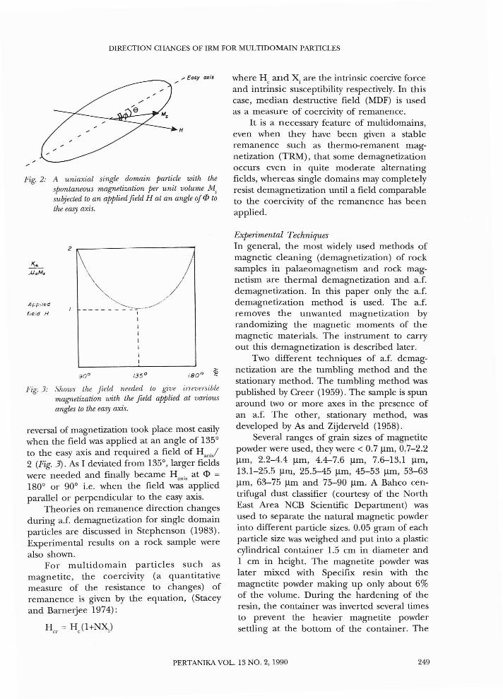
Fig. 2: A uniaxial single domain particle with thespontaneous magnetization per unit volume M,subjected to an applied field H at an angle ofep tothe easy axis.
2 .-------------~
App,ied
fie;d H
Fig. 3: Shows the Jield needed to give irreversiblemagnetization with the field applied at variousangles to the easy axis.
reversal of magnetization took place most easilywhen the field was applied at an angle of 135°to the easy axis and required a field of H . /2 (Fig. 3). As I deviated from 135°, larger fi~'idswere needed and finally became H anis at <I> =
180° or 90° i.e. when the field was appliedparallel or perpendicular to the easy axis.
Theories on remanence direction changesduring a.f. demagnetization for single domainparticles are discussed in Stephenson (1983).Experimental results on a rock sample werealso shown.
For multidomain particles such asmagnetite, the coercivity (a quantitativemeasure of the resistance to changes) ofremanence is given by the equation, (Staceyand Barnerjee 1974):
Her = He(I+NX)
where He and Xi are the intrinsic coercive forceand intrinsic susceptibility respectively. In thiscase, median destructive field (MDF) is usedas a measure of coercivity of remanence.
It is a necessary feature of multidomains,even when they have been given a stableremanence such as thermo-remanent magnetization (TRM), that some demagnetizationoccurs even in quite moderate alternatingfields, whereas single domains may completelyresist demagnetization until a field comparableto the coercivity of the remanence has beenapplied.
Experimental TechniquesIn general, the most widely used methods ofmagnetic cleaning (demagnetization) of rocksamples in palaeomagnetism and rock magnetism are thermal demagnetization and a.f.demagnetization. In this paper only the a.f.demagnetization method is used. The a.f.removes the unwanted magnetization byrandomizing the magnetic moments of themagnetic materials. The instrument to carryout this demagnetization is described later.
Two different techniques of a.f. demagnetization are the tumbling method and thestationary method. The tumbling method waspublished by Creer (1959). The sample is spunaround two or more axes in the pres~nce ofan a.f. The other, stationary method, wasdeveloped by As and Zijderveld (1958).
Several ranges of grain sizes of magpetitepowder were used, they were < 0.7 !lm, 0,7-2.2!lm, 2.2-4.4 !lm, 4.4-7.6 !lm, 7.6--13.1 !lm,13.1-25.5 !lm, 25.5-45 !lm, 45-53 !lm, 53-63!lm, 63-75 !lm and 75-90 !lm. A Bahco centrifugal dust classifier (courtesy of the NorthEast Area NCB Scientific Department) wasused to separate the natural magnetic powderinto different particle sizes. 0.05 gram of eachparticle size was weighed and put into a plasticcylindrical container 1.5 em in diameter and1 em in height. The magnetite powder waslater mixed with Specifix resin with themagnetite powder making up only about 6%of the volume. During the hardening of theresin, the container was inverted several timesto prevent the heavier magnetite powdersettling at the bottom of the container. The
PERTANIKA VOL. 13 NO.2, 1990 249
SABAT SADIKUN AND AlAN STEPHENSON
container was then put into a perspex sampleholder making the size of the sample 2.54 cmini diameter and 2.54 cm in height.
The measurement of remanent magnetizations were made using the Molspinmagnetometer which is based on the spinnermagnetometer design of Mlyneux (1971). Inmeasuring the magnetization of a specimen,the specimen is rotated within a ring fluxgate.The signal is then read 128 times perrevolution of the sample and is passed to acomputer which stores and processes the data.The specimen is rotated twice about eachprincipal axis to reduce the effect ofinhomogenity of the remanence of thespecimen. It takes about 2 min to obtain thedirection and intensity of the magnetizationof each sample from all the six rotations.
The limit of measurement of weakspecimens is set by the noise level of theinstrument and can be determined by doingthe same measurement procedure without asample present. The noise level decreases withthe square root of the rotation time and isabout 2.5xl0-5 A/m for 24 revolutions. Thecalibration of the instrument is done using astandard sample.
The demagnetization process was carriedout using an a.f. demagnetizer. The maximumfield of the demagnetizer is 100 mT at 200Hz. Two types of demagnetization can becarried out using this instrument. For tumblingdemagnetization, the sample is put in atumbler container and tumbled about twoperpendicular axes. For stationary demagnetization, the sample is simply placed at arequired orientation to the axis of the demagnetization coil. Demagnetization is carried outby the demagnetization coil which producesan a.f. along its axis. The field in the coil isthen slowly returned to zero. The sample isshielded from the earth's magnetic field by adouble-walled Mu metal bucket shield.
A pulse magnetizer was used in. theapplication of IRM to samples. The instrumentwhich is portable, produces a pulse magneticfield of width 10 msec and of variable heightup to 300 mT. The pulse is produced bydischarging a bank of capacitors through acoil.
Before the experiment, the magnetitesamples were demagnetized by tumbling to themaximum field of the demagnetizationinstrument (100 mT). The samples were thengiven an IRM in 40 mT along their Z axes.For constancy, all samples were oriented in thesame position (i.e. the x axis of every samplein a particular direction) in the pulsemagnetizer for every IRM application. Thenthe static single-axis demagnetization wascarried out by mounting the sample on a nonmagnetic orientation device. The Z axis of thesample was set at 15° to the a.f. axis, i.e. thea.f. was at (0°,45°) (declination, inclination).The demagnetization was done stepwise up tothe peak field of 80 mT for all the samples.
RESULTS AND DISCUSSION
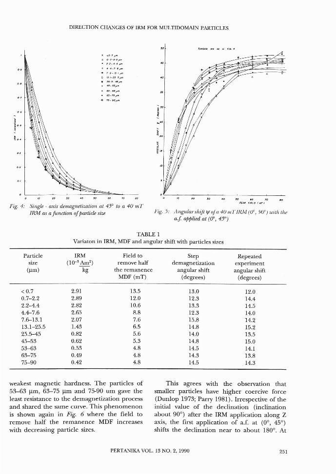
Fig. 4 shows the variation of intensity of themagnetization of the sample as the peak fieldis increased. According to Stephenson (1983),the application of IRM along the Z axis withthe a.f. at (0°, 45°) for single domain particleswould change the inclination without affectingthe declination. During this demagnetizationprocess, there was, however, also a slightchange in the declination due to theorientation of the IRM being slightlymisaligned with the Z axis. Hence, the angularchange lfI, of the IRM vector for eachdemagnetization field was calculated using acomputer. Fig. 5 shows this angular changewith increasing peak field.
The demagnetization field needed toremove half the remanence MDF (mediandestructive field) of each sample wasdetermined from Fig. 4 and is listed in Table1. Parry (1981) used MDF as an index ofstability. The angular shift for each MDF forthe step demagnetization was determined fromFig. 5 and is listed in Table 1.
The experiment was repeated with eachsample demagnetized at each MDF and theangular shift lfI calculated and listed in Table1. Table 1 shows that the remanence acquiredin a 40 mT IRM decreases with decreasingparticle size. The intensity graphs in Fig. 4 showthat the resistance to the demagnetizationprocess increases with decreasing particle size.The particle of 75-90 11m exhibited the
250 PERTANIKA VOL. 13 NO.2, 1990
DIRECTION CHANGES OF IRM FOR MULTIDOMAlN PARTICLES
'0 Symbon ~. .u i" FIG."
IC <0' 7 1"111
.0 Q. 7*2·2 /"111
• 2-2-"''',o "." .7· f,..,.+ 7 f - 13-/1"'"
o IJ /-Z,-,,'"• 2$-'· "'..-'".. "'·'S,,,.0 "-6S ..
• n." ........ 75_ .0,..",
Fig. 4: Single - axis demagnetization at 45° to a 40 11ITIBM as a function ofparticle size
50 60 70 aoPEAl< FIEL 0 ( lilT J
Fig.5: Angularsltiji 'IIuJa4UmFlluH (if, Yif) witlttltea.f applied at ((J', 4jO)
TABLE 1Variaton in IRM, MDF and angular shift with particles sizes
Particle IRM Field to Step Repeatedsize (10-3 Am2 ) remove half demagnetization experiment
(Ilm ) kg the remanence angular shift angular shiftMDF (mT) (degrees) (degrees)
< 0.7 2.91 13.5 13.0 12.00.7-2.2 2.89 12.0 12.3 14.42.2-4.4 2.82 10.6 13.3 14.54.4-7.6 2.65 8.8 12.3 14.07.6-13.1 2.07 7.6 15.8 14.213.1-25.5 1.43 6.5 14.8 15.225.5-45 0.82 5.6 14.0 13.545-53 0.62 5.3 14.8 15.053-63 0.53 4.8 14.5 14.163-75 0.49 4.8 14.3 13.875-90 0.42 4.8 14.5 14.3
weakest magnetic hardness. The particles of53-63 j.lm, 63-75 j.lm and 75-90 urn gave theleast resistance to the demagnetization processand shared the same curve. This phenomenonis shown again in Fig. 6 where the field toremove half the remanence MDF increaseswith decreasing particle sizes.
This agrees with the observation thatsmaller particles have higher coercive force(Dunlop 1973; Parry 1981). Irrespective of theinitial value of the declination (inclinationabout 90°) after the IRM application along Zaxis, the first application of a.f. at (0°, 45°)shifts the declination near to about 180°. At
PERTANlKA VOL. 13 NO.2, 1990 251

SAHAT SADIKUN AND AlAN STEPHENSON
16
12
:~ 30;
10 IUO
GRAIN SIZE (pm )
Fig. 0: .\/lJFjlllilll·sil/glp-axisr/(,lIIagnptiwtiol/ at 45° toa -If! IIII' IIL\1 as a jlll/rtiol/ o/jHIl·tidf'siZ('
Z axis
+
0+, .
Fig. 8: Angularshiftlflfor the single -axis demagnetizationat 45° to a 40 mTJRM as afunction offraction ofJR1V1 removed
IRM of fhe end
of the demognefirofion
prOctlSS {180~450J
// 0.1. axis/ {OO 45 0 J
/ J J
/
lL..._+--~,---->7' X axis
0.2
+
0.4 06 08
FRACTION OF IRM REMOVEO
~ Y oxis
Fig. 7: The diratiDn of the remanence vector at the end ofsi IIgh' - axis r/f'lllagnptization
the end of the a.f. demagnetization when mostof the remanence has been removed, it alwayslies at about (180°, 45°), which is perpendicular to the a.f. axis (see Fig. 7).
Fig. 5 shows that at the early stage ofthe demagnetization process, the largestparticles (75-90 flm) gave the greatestangular shift and the smallest particles « 0.7flm) gave the smallest angular shift. However,as the demagnetization proceeded, theangular shift for all the particle sizereached a limit of about 45°. Above 30 mT,the angular shift was more scattered as morethan 80% of the remanence had beenremoved.
The angular shift If! as a function of thefraction of the IRM removed is plotted in Fig.8. This plot allows for different magnetichardness of different particle sizes. The angularshift If! for all the particle sizes is a function ofthe IRM removed, i.e.
[IRMHJ
If! = f IRMo
where IRMH is the remanence (IRM) at aparticular a.f. and IRM
ois the initial
remanence (IRM) at zero a.f.The angular shift when half the
remanence was removed (MDF) during thestep demagnetization and the repeated
16
10
GI?AIN SLZE {pm}
Fig. 9: Angular shift for the single - axis demagnetizationat 45° to a 40 mT JRM at MDF as afunction ofpaTtiele size
252 PERTANlKA VOL. 13 NO.2, 1990
DIRECTION CHANGES OF IRM FOR MULTIDOMAIN PARTICLES
b <'0.7;Jm
.. 75- 90"um
40PEAK FIELD (mT)
40 50OECLINAnON (dlg,,.s}
A <O.7jJm
'" 75-90jlm
• Fit/ol up.cl.d dlT.Cfiof
30
30
20
20
,"t-fl..,," I' :,,'
~. ., ?II'
.~//
10
10
o
10
20
30
1.0
OL---__'----""""""'=-&_---:--=::==~_
multidomain particles increase with decreasingparticle size as can be seen from the result ofsingle-and three-axis demagnetization. Threeaxis demangnetization of IRM at (15°, 15°)showed a general migration towards (45°,35.3°) as found by Stephenson (1983) for arock sample.
ACKNOWLEDGEMENTS
The experiments were carried out at TheSchool of Physics, University of Newcastle uponTyne, England. I would like to thank the SabahFoundation and Universiti KebangsaanMalaysia for the financial support.
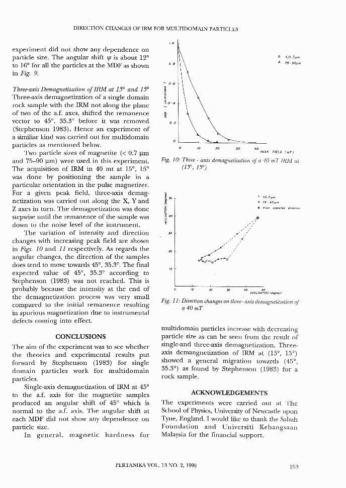
Fig. 11: Direction changes on three- axis demagnetization ofa40mT
Fig. 10: Three - axis demagnetization of a 40 mT IRJv1 at(1:;0,15")
Three-axis Demagnetization of IRM at 15° and 15°Three-axis demagnetization of a single domainrock sample with the IRM not along the planeof two of the a.f. axes, shifted the remanencevector to 45°, 35.3° before it was removed(Stephenson 1983). Hence an experiment ofa similiar kind was carried out for multidomainparticles as mentioned below.
Two particle sizes of magnetite « 0.7 !lmand 75-90 !lm) were used in this experiment.The acquisition of IRM in 40 mt at 15°, 15°was done by positioning the sample in aparticular orientation in the pulse magnetizer.For a given peak field, three-axis demagnetization was carried out along the X, Y andZ axes in turn. The demagnetization was donestepwise until the remanence of the sample wasdown to the noise level of the instrument.
The variation of intensity and directionchanges with increasing peak field are shownin Figs. 10 and 11 respectively. As regards theangular changes, the direction of the samplesdoes tend to move towards 45°,35.3°. The finalexpected value of 45°, 35.3° according toStephenson (1983) was not reached. This isprobably because the intensity at the end ofthe demagnetization process was very smallcompared to the initial remanence resultingin spurious magnetization due to instrumentaldefects coming into effect.
CONCLUSIONS
experiment did not show any dependence onparticle size. The angular shift lfI is about 12°to 16° for all the particles at the MDF as shownin Fig. 9.
The aim of the experiment was to see whetherthe theories and experimental results putforward by Stephenson (1983) for singledomain particles work for multidomainparticles.
Single-axis demagnetization of IRM at 45°to the a.f. axis for the magnetite samplesproduced an angular shift of 45° which isnormal to the a.f. axis. The angular shift ateach MDF did not show any dependence onparticle size.
In general, magnetic hardness for
PERTANlKA VOL. 13 NO.2, 1990 253

SABAT SADIKUN AND ALAN STEPHENSON
REFERENCES
As, J.A. and J.DA ZIJDERVELD. 1958. MagneticCleaning of Rocks in Palaeomagnetic Research.Geophys. JR Astron. Soc. 1: 308-19.
COLLINSON, D.W. 1983. Methods in Rock Magnetismand Palaeomagnetism: Techniques and Instrumentation. London, New York: Chapman &Hall.
CREER, KM. 1959. A.C. Demagnetization of UnstableTriassic Keuper Marls from S.W. England. Geophys. JR. Astron. Soc. 2: 261-75.
DUNLOP, DJ. 1973. Superparamagnetic and Singledomain Threshold Sizes in Magnetite. JGeophys. Res. 78: 1780-93.
KITTEL, C. 1946. Theory and Structure of Ferromagnetic Domains in Film and Small Particles.Phys. Rev. 70: 965-71.
MOLYNEUX, L. 1971. A Complete Result Magnetometer for Measuring the Remanent Magnetization of Rocks. Geophys. JR. Astron. Soc. 42933.
NAGATA, T.K KOBAYASHI and M.D. FULLER. 1964.Identification of Magnetite and Haematite inRocks by Magnetic Observation at Low Temperature. J Geophys. Res. 69: 2111-20.
PARRY, L.G. 1965. Magnetic Properties of DispersedMagnetic Powders. Philo. Mag. 11: 303-12.
PARRY, L.G. 1981. The Influence of Fine Structureson the Remanence of Multidomain Particles ofMagnetite and Titanomagnetite. Earth Planet.Int. 26: 63-71.
SCHMIDLIN, H. 1937. Uber entmagnetisierendeWirkung der Anderungen des magnetishenErdfeldes. Eeitr. Angew. Geophys. 7: 94-111.
SOFFEL, H.C. 1981. Domain Structure of NaturalFine Grained Pyrrhotite in Rock Matrix (diabase). Phys. Earth Planet. Int. 98: 106.
STACEY, F.D. and S.K BANERJEE. 1974. The PhysicalPrinciples of Rock Magnetism. Amsterdam:Elsevien.
STEPHENSON, A. 1983. Changes in Direction ofRemanence of Rocks Produced by StationaryAlternating Field Demagnetization. Geophys. JRAstron. Soc. 73: 213-39.
STONER, E.C. and E.P. WOLFARTH. 1948. AMechanism of Magnetic Hysteresis inHetereogenous Alloys. Philos. Trans. Roy. Soc(London). A240: 599-644.
(Received 20 January, 1989)
254 PERTANlKA VOL. 13 NO.2, 1990