Direct torque control of dual star induction motor using a ...
16
Direct torque control of dual star induction motor using a fuzzy-PSO hybrid approach Ghoulemallah Boukhalfa, Sebti Belkacem, Abdesselem Chikhi and Said Benaggoune Department of Electrical Engineering, Faculty of Technology, University of Batna2, Fesdis, Algeria Abstract This paper presents the particle swarm optimization (PSO) algorithm in conjuction with the fuzzy logic method in order to achieve an optimized tuning of a proportional integral derivative controller (PID) in the DTC control loops of dual star induction motor (DSIM). The fuzzy controller is insensitive to parametric variations, however, with the PSO-based optimization approach we obtain a judicious choice of the gains to make the system more robust. According to Matlab simulation, the results demonstrate that the hybrid DTC of DSIM improves the speed loop response, ensures the system stability, reduces the steady state error and enhances the rising time. Moreover, with this controller, the disturbances do not affect the motor performances. Keywords Dual stator induction motor (DSIM), Direct torque control (DTC), Speed control, particle swarm optimization (PSO), Fuzzy logic control (FLC) Paper type Review Article Nomenclature P Number of pole pairs J The moment of inertia f r The friction coefficient T em The electromagnetic torque T r The load torque Ω r is the mechanical rotation speed of the rotor R s1 ,R s2 Stators resistances R r Rotor resistance L s1 ,L s2 Stators inductances L r Rotor Inductance L m Mutual inductance n number of particles in the group d dimension index t pointer of iterations (generations) Direct torque control of dual star induction motor © Ghoulemallah Boukhalfa, Sebti Belkacem, Abdesselem Chikhi and Said Benaggoune. Published in Applied Computing and Informatics. Published by Emerald Publishing Limited. This article is published under the Creative Commons Attribution (CC BY 4.0) license. Anyone may reproduce, distribute, translate and create derivative works of this article (for both commercial and non-commercial purposes), subject to full attribution to the original publication and authors. The full terms of this license may be seen at http://creativecommons.org/licences/by/4.0/legalcode Publishers note: The publisher wishes to inform readers that the article “Direct torque control of dual star induction motor using a fuzzy-PSO hybrid approach” was originally published by the previous publisher of Applied Computing and Informatics and the pagination of this article has been subsequently changed. There has been no change to the content of the article. This change was necessary for the journal to transition from the previous publisher to the new one. The publisher sincerely apologises for any inconvenience caused. To access and cite this article, please use Boukhalfa, G., Belkacem, S., Chikhi, A., Benaggoune, S. (2020), “Direct torque control of dual star induction motor using a fuzzy-PSO hybrid approach”, New England Journal of Entrepreneurship, Vol. ahead-of-print No. ahead-of-print. https://10.1016/j.aci.2018.09.001. The original publication date for this paper was 06/09/2018. The current issue and full text archive of this journal is available on Emerald Insight at: https://www.emerald.com/insight/2210-8327.htm Received 15 April 2018 Revised 19 August 2018 Accepted 2 September 2018 Applied Computing and Informatics Emerald Publishing Limited 2210-8327 DOI 10.1016/j.aci.2018.09.001
Transcript of Direct torque control of dual star induction motor using a ...
Direct torque control of dual starinduction motor using a fuzzy-PSO
hybrid approachGhoulemallah Boukhalfa, Sebti Belkacem, Abdesselem Chikhi and
Said BenaggouneDepartment of Electrical Engineering, Faculty of Technology, University of Batna2,
Fesdis, Algeria
AbstractThis paper presents the particle swarm optimization (PSO) algorithm in conjuctionwith the fuzzy logic methodin order to achieve an optimized tuning of a proportional integral derivative controller (PID) in the DTC controlloops of dual star inductionmotor (DSIM). The fuzzy controller is insensitive to parametric variations, however,with the PSO-based optimization approach we obtain a judicious choice of the gains to make the system morerobust. According to Matlab simulation, the results demonstrate that the hybrid DTC of DSIM improves thespeed loop response, ensures the system stability, reduces the steady state error and enhances the rising time.Moreover, with this controller, the disturbances do not affect the motor performances.
Keywords Dual stator induction motor (DSIM), Direct torque control (DTC), Speed control, particle swarm
optimization (PSO), Fuzzy logic control (FLC)
Paper type Review Article
NomenclatureP Number of pole pairsJ The moment of inertiafr The friction coefficientTem The electromagnetic
torqueTr The load torqueΩr is the mechanical
rotation speed ofthe rotor
Rs1, Rs2 Stators resistances
Rr Rotor resistanceLs1, Ls2 Stators inductancesLr Rotor InductanceLm Mutual inductancen number of particles in
the groupd dimension indext pointer of iterations
(generations)
Direct torquecontrol of dualstar induction
motor
© Ghoulemallah Boukhalfa, Sebti Belkacem, Abdesselem Chikhi and Said Benaggoune. Published inApplied Computing and Informatics. Published by Emerald Publishing Limited. This article is publishedunder the Creative Commons Attribution (CC BY 4.0) license. Anyone may reproduce, distribute,translate and create derivative works of this article (for both commercial and non-commercial purposes),subject to full attribution to the original publication and authors. The full terms of this license may beseen at http://creativecommons.org/licences/by/4.0/legalcode
Publishers note: The publisher wishes to inform readers that the article “Direct torque control ofdual star induction motor using a fuzzy-PSO hybrid approach” was originally published by theprevious publisher of Applied Computing and Informatics and the pagination of this article has beensubsequently changed. There has been no change to the content of the article. This change wasnecessary for the journal to transition from the previous publisher to the new one. The publishersincerely apologises for any inconvenience caused. To access and cite this article, please useBoukhalfa, G., Belkacem, S., Chikhi, A., Benaggoune, S. (2020), “Direct torque control of dual starinduction motor using a fuzzy-PSO hybrid approach”, New England Journal of Entrepreneurship, Vol.ahead-of-print No. ahead-of-print. https://10.1016/j.aci.2018.09.001. The original publication date forthis paper was 06/09/2018.
The current issue and full text archive of this journal is available on Emerald Insight at:
https://www.emerald.com/insight/2210-8327.htm
Received 15 April 2018Revised 19 August 2018
Accepted 2 September 2018
Applied Computing andInformatics
Emerald Publishing Limited2210-8327
DOI 10.1016/j.aci.2018.09.001
vti,m velocity of particle atiteration I
w inertia weight factorrand ( ) randomnumber between
0 and 1
pbesti best previous position ofthe ith particle
gbest best particle among allthe particles inthe population
C1,C2 acceleration constantsubscripts s, r indicate the variables
and parameters of
stators and rotor,respectively
subscripts 1, 2 denote variables andparameters of stator 1and 2 respectively
Vds1, Vqs1, Vds2, Vqs2 respectively statorvoltages in the d-q axis
Ids1, Iqs1, Ids2, Iqs2 components of the statorcurrents in the d - q axis
Idr, Iqr the rotor currentsψds1, ψqs1, ψds2, ψqs2 components of the stator
flux linkage vectors ind-q axis
ψdr, ψqr respectively rotor fluxes
1. IntroductionIn high-power applications, the dual star induction motor has largely replaced the inductionmachines whose roles were predominant in the industry [1–5]. The dual star induction motoris constituted of two windings with phases shifted from one another by an angle of 30electrical degrees. These windings are usually powered by a six-phase inverter fed byvariable speed drives. The main advantages of the DSIM are: [6] their higher torque density,reduced harmonic content of the DC link current and the reliability of this machine whichallows a functioning with one or several phases of defective motor. However the control ofDSIM is considered to be complicated because the difficulty of obtaining the decoupling of thetorque and the flux. To overcome these difficulties, high-performance algorithms have beendeveloped [7–14].
To satisfy the performance of an electromechanical system drive, the generally usedstrategy consists in controlling the speed by a PID controller to cancel the static error andreduce the response time. This speed is often characterized by an overshoot at startup anddepends on the parameters of the machine. In order to overcome these complications, severalmethods have been developed to adjust the PID regulator.
Auto-tuning is one of these methods, which is used in PID controllers [15]. Theperformance of the control loops is improved by automatically adjusting the PID gainparameters of the conventional controllers.
The self-tuning method has been suggested by many researchers [16,17]. A self-adjusting mechanism has been set up to adapt the PID regulator in case of anydisturbances.
The use of optimization algorithms as alternative methods for tuning PID controllershas been a recent topic of research in electric machines control. New optimizationtechniques are proposed, for instance, the Imperialist Competitive Algorithm (ICA) [18],evolutionary algorithm [19], Genetic Algorithm (GA) [20–21], BAT algorithm [22],Particle Swarm Optimization (PSO) [23–26], and Ant Colony Optimization (ACO)algorithm [27], Harmony Search (HS) [28], hybrid GA [29–30], adaptive Cuckoo Searchalgorithm (CS) [31].
PSO was first used by Eberhart and Kennedy in 1995 [32]. This approach isinspired by the social behavior shown by the natural species. In recent years, particleswarm optimization has appeared as a new and popular optimization algorithm dueto its simplicity and efficiency. The role of the PSO in this study is to suggest anadequate adjustment of the parameters (kp, Ki, Kd) to satisfy some drive systemrequirements.
ACI
In last years, the FLC has improved results of nonlinear and complex processes [33]. Themain idea of this approach is that it does not need a precise mathematical model of the electricmachine, FLCs are robust and their performance is insensitive to parameter variations. Withthe increasing evolution of approximation theory, the adaptive control methods have beenpresented to cope with the nonlinear systems with parametric uncertainty based on fuzzylogic system (FLS) [34], neural networks (NNs) [35], adaptive fuzzy and NN controlapproaches via backstepping methods [36,37].
There are two disadvantages in the conception of a FLC. The first one is the obtaining of asuitable rule-base for the application, while the second is the selection of scaling factors priorto fuzzification and after defuzzification, in order to overwhelm these drawbacks andexpedite the determination of the design parameters and to reduce the time consumption.Several solutions are adapted to remedy these problems. In [38,39] the authors presents an online method for adapting the scaling factors of the FLC, the authors suggest a solution todesign an adaptive fuzzy controller. The objective of the proposed form is to adapt onlinescaling factors according to a performance measure in order to refine the controller andincrease the performance of the drive system.
In this paper, we investigate the performance of PSO for optimizing the gains of the fuzzy-PID speed controller of the DSIM.
2. Modeling of the dual star induction motorThe DSIM dynamic equations in the reference d-q can be reported as follow [4]:8>>>>>>>>>>>>>>>>>>>>>><
>>>>>>>>>>>>>>>>>>>>>>:
Vds1 ¼ Rs1ids1 þ d ψds1
dt� ωsψqs1
Vqs1 ¼ Rs1iqs1 þd ψqs1
dtþ ωsψds1
Vds2 ¼ Rs2ids2 þ d ψds2
dt� ωsψqs2
Vqs2 ¼ Rs2iqs2 þd ψqs2
dtþ ωsψds2
Vdr ¼ 0 ¼ Rridr þ d ψdr
dt� ðωs � ωrÞψqr
Vqr ¼ 0 ¼ Rriqr þd wqr
dtþ ðωs � ωrÞwdr
(1)
where the fluxes equations are:8>>>>>><>>>>>>:
ψds1 ¼ Ls1ids1 þ Lmðids1 þ ids2 þ idrÞψqs1 ¼ Ls1iqs1 þ Lmðiqs1 þ iqs2 þ iqrÞψds2 ¼ Ls2ids2 þ Lmðids1 þ ids2 þ idrÞψqs1 ¼ Ls1iqs1 þ Lmðiqs1 þ iqs2 þ iqrÞψdr ¼ Lridr þ Lmðids1 þ ids2 þ idrÞψqr ¼ Lriqr þ Lmðiqs1 þ iqs2 þ iqrÞ
(2)
For studying the dynamic behavior, the following equation of motion was added:
JdΩr
dt¼ Tem � Tr � frΩr (3)
Direct torquecontrol of dualstar induction
motor
The model of the DSIM has been completed by the expression of the electromagnetic torqueTem given below:
Tem ¼ pLm
Lm þ Lr
ðψdrðiqs1 þ iqs2Þ � ψqrðids1 þ ids2ÞÞ (4)
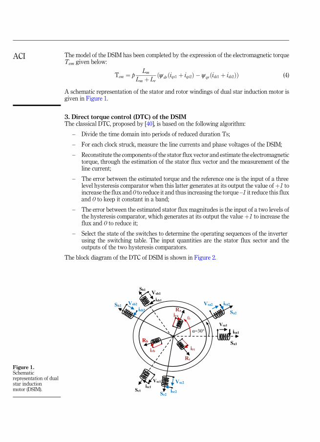
A schematic representation of the stator and rotor windings of dual star induction motor isgiven in Figure 1.
3. Direct torque control (DTC) of the DSIMThe classical DTC, proposed by [40], is based on the following algorithm:
– Divide the time domain into periods of reduced duration Ts;
– For each clock struck, measure the line currents and phase voltages of the DSIM;
– Reconstitute the components of the stator flux vector and estimate the electromagnetictorque, through the estimation of the stator flux vector and the measurement of theline current;
– The error between the estimated torque and the reference one is the input of a threelevel hysteresis comparator when this latter generates at its output the value ofþ1 toincrease the flux and 0 to reduce it and thus increasing the torque –1 it reduce this fluxand 0 to keep it constant in a band;
– The error between the estimated stator flux magnitudes is the input of a two levels ofthe hysteresis comparator, which generates at its output the valueþ1 to increase theflux and 0 to reduce it;
– Select the state of the switches to determine the operating sequences of the inverterusing the switching table. The input quantities are the stator flux sector and theoutputs of the two hysteresis comparators.
The block diagram of the DTC of DSIM is shown in Figure 2.
Vsb1Sb1
Sc2isc2Sc1
Sa2
Sb2
α=30°
θr
Ra
Rb
Rc
Vsa1
Vsa2 isa2isb1Vsb2
isb2
Vsc1isc1
Vsc2
ira
irb ircSa1
isa1
Figure 1.Schematicrepresentation of dualstar inductionmotor (DSIM).
ACI
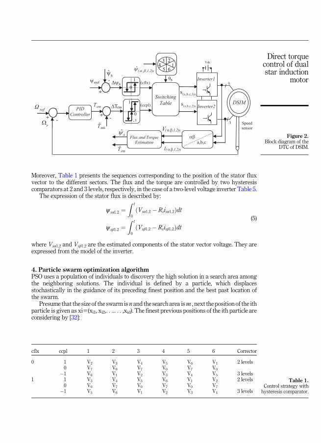
Moreover, Table 1 presents the sequences corresponding to the position of the stator fluxvector to the different sectors. The flux and the torque are controlled by two hysteresiscomparators at 2 and 3 levels, respectively, in the case of a two-level voltage inverter Table 5.
The expression of the stator flux is described by:
ψ sα1:2 ¼Z t
0
ðVsα1;2 � Rsisα1;2Þdt
ψ sβ1:2 ¼Z t
0
ðVsβ1;2 � Rsisβ1;2Þdt(5)
where Vsα1;2 and Vsβ1;2 are the estimated components of the stator vector voltage. They areexpressed from the model of the inverter.
4. Particle swarm optimization algorithmPSO uses a population of individuals to discovery the high solution in a search area amongthe neighboring solutions. The individual is defined by a particle, which displacesstochastically in the guidance of its preceding finest position and the best past location ofthe swarm.
Presume that the size of the swarm is n and the search area ism , next the position of the ithparticle is given as xi5(xi1, xi2,. . ... . . ,xid). The finest previous positions of the ith particle areconsidering by [32]:
cflx ccpl 1 2 3 4 5 6 Corrector
0 1 V2 V3 V4 V5 V6 V1 2 levels0 V7 V0 V7 V0 V7 V0
�1 V6 V1 V2 V3 V4 V5 3 levels1 1 V3 V4 V5 V6 V1 V2 2 levels
0 V0 V7 V0 V7 V0 V7
�1 V5 V6 V1 V2 V3 V4 3 levels
Speed
sensor
3
3
(a,b,c,1)ss
Flux and Torque Estimation
ˆ s
s
DSIM Switching
Table (ccpl)
1
0 +
- (cflx) sref
+-
Inverter2
s
( , ,1,2)sI
sψ̂ˆ( , ,1,2)s
(a,b,c,2)ss
Inverter1
Vdc
( , ,1,2)sV
a,b,c
refΩ
r
+ -
PID Controller
1 2 3
4 5 6
1
-1
0
emT
emΤ̂
ˆem Τ
em Τ
Table 1.Control strategy with
hysteresis comparator.
Figure 2.Block diagram of the
DTC of DSIM.
Direct torquecontrol of dualstar induction
motor
pbesti ¼ ðpbesti1; pbesti2; :::; pbestidÞ (6)
The index of the best particle amongst the group is gbestd. The velocity of particle ith isrepresented as:
vi ¼ ðvi1; vi2; ::::; vidÞ (7)
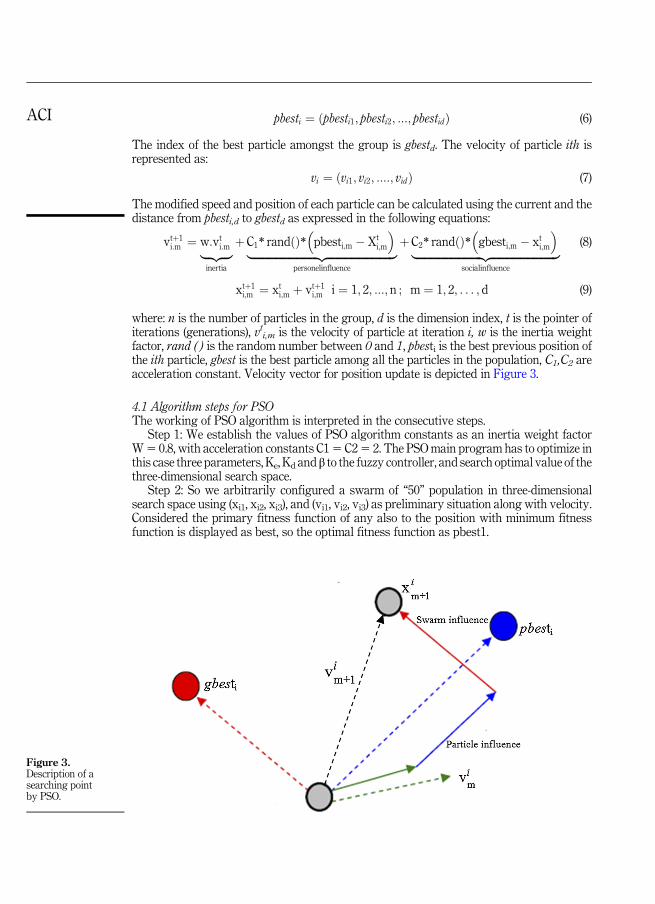
The modified speed and position of each particle can be calculated using the current and thedistance from pbesti,d to gbestd as expressed in the following equations:
vtþ1i:m ¼ w:vti:m|fflffl{zfflffl}
inertia
þC1* randðÞ*�pbesti;m � Xt
i;m
�|fflfflfflfflfflfflfflfflfflfflfflfflfflfflfflfflfflfflfflfflfflfflfflfflffl{zfflfflfflfflfflfflfflfflfflfflfflfflfflfflfflfflfflfflfflfflfflfflfflfflffl}
personelinfluence
þC2* randðÞ*�gbesti;m � xti;m
�|fflfflfflfflfflfflfflfflfflfflfflfflfflfflfflfflfflfflfflfflfflfflfflfflffl{zfflfflfflfflfflfflfflfflfflfflfflfflfflfflfflfflfflfflfflfflfflfflfflfflffl}
socialinfluence
(8)
xtþ1i;m ¼ xti;m þ vtþ1
i;m i ¼ 1; 2; :::; n ; m ¼ 1; 2; . . . ; d (9)
where: n is the number of particles in the group, d is the dimension index, t is the pointer ofiterations (generations), vti,m is the velocity of particle at iteration i, w is the inertia weightfactor, rand ( ) is the random number between 0 and 1, pbesti is the best previous position ofthe ith particle, gbest is the best particle among all the particles in the population, C1,C2 areacceleration constant. Velocity vector for position update is depicted in Figure 3.
4.1 Algorithm steps for PSOThe working of PSO algorithm is interpreted in the consecutive steps.
Step 1: We establish the values of PSO algorithm constants as an inertia weight factorW5 0.8, with acceleration constants C15 C25 2. The PSOmain program has to optimize inthis case three parameters, Ke, Kd and β to the fuzzy controller, and search optimal value of thethree-dimensional search space.
Step 2: So we arbitrarily configured a swarm of “50” population in three-dimensionalsearch space using (xi1, xi2, xi3), and (vi1, vi2, vi3) as preliminary situation along with velocity.Considered the primary fitness function of any also to the position with minimum fitnessfunction is displayed as best, so the optimal fitness function as pbest1.
Figure 3.Description of asearching pointby PSO.
ACI
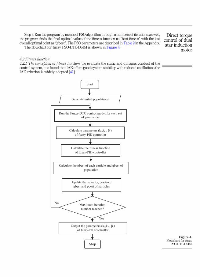
Step 3: Run theprogrambymeans of PSOalgorithm throughn numbers of iterations, aswell,the program finds the final optimal value of the fitness function as “best fitness” with the lastoverall optimal point as “gbest”. The PSO parameters are described in Table 2 in the Appendix.
The flowchart for fuzzy PSO-DTC-DSIM is shown in Figure 4.
4.2 Fitness function4.2.1 The conception of fitness function. To evaluate the static and dynamic conduct of thecontrol system, it is found that IAE offers good system stability with reduced oscillations theIAE criterion is widely adopted [41]:
Yes
No
Run the Fuzzy-DTC control model for each set
of parameters
Start
Generate initial populations
Calculate parameters (ke,kd , β )
of fuzzy-PID controller
Calculate the fitness function
of fuzzy-PID controller
Calculate the pbest of each particle and gbest of
population
Update the velocity, position,
gbest and pbest of particles
Stop
Maximum iteration
number reached?
Output the parameters (ke,kd , β )
of fuzzy-PID controller
Figure 4.Flowchart for fuzzy
PSO-DTC-DSIM.
Direct torquecontrol of dualstar induction
motor
IAE ¼Z
∞
0
jeðtÞjdt (10)
5. Design of PID-PSO controller type FLC for the DSIMThe optimization of the FLC gains using PSO can be given by the input variable {e}, and theerror change {ec} as follows:
eðtÞ ¼ Ωref �ΩrðtÞ (11)
ecðtÞ ¼ deðtÞdt
(12)
Table 3 illustrated the performance of PID controller in the AppendixThe fuzzy PI controller is the commonly used because the PD one encounters difficulties in
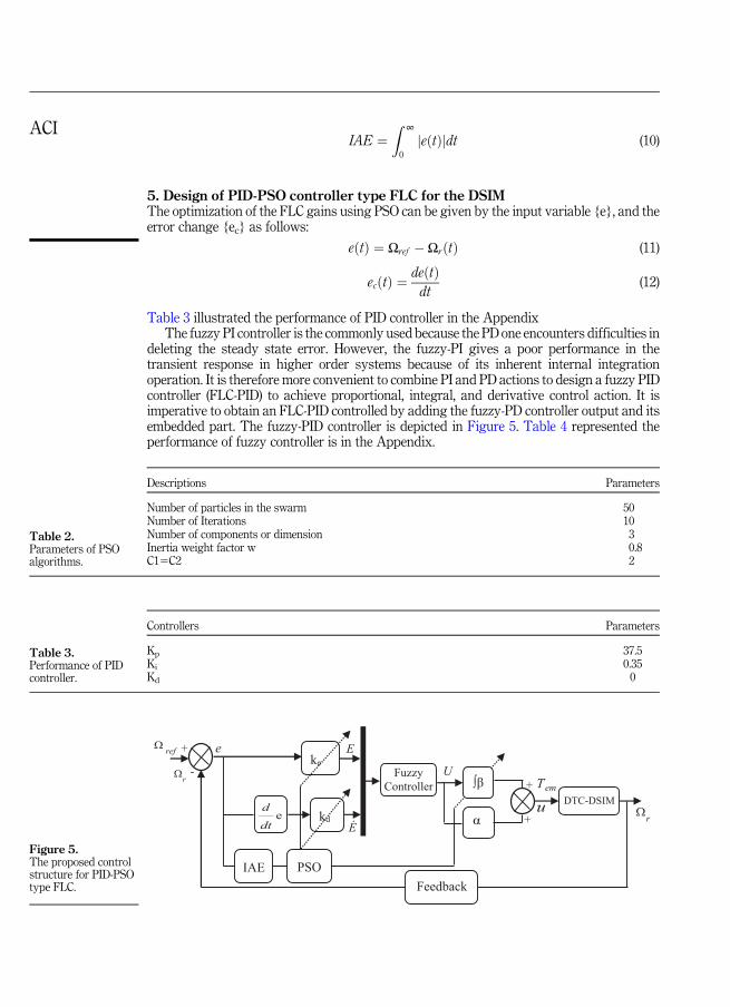
deleting the steady state error. However, the fuzzy-PI gives a poor performance in thetransient response in higher order systems because of its inherent internal integrationoperation. It is therefore more convenient to combine PI and PD actions to design a fuzzy PIDcontroller (FLC-PID) to achieve proportional, integral, and derivative control action. It isimperative to obtain an FLC-PID controlled by adding the fuzzy-PD controller output and itsembedded part. The fuzzy-PID controller is depicted in Figure 5. Table 4 represented theperformance of fuzzy controller is in the Appendix.
Controllers Parameters
Kp 37.5Ki 0.35Kd 0
Descriptions Parameters
Number of particles in the swarm 50Number of Iterations 10Number of components or dimension 3Inertia weight factor w 0.8C15C2 2
ke
kdeddt α
PSO IAE
e
Fuzzy
Controller em Τ-
+
r
Feedback
u
U
E
E
ref
DTC-DSIM
+
+
r
Table 3.Performance of PIDcontroller.
Table 2.Parameters of PSOalgorithms.
Figure 5.The proposed controlstructure for PID-PSOtype FLC.
ACI
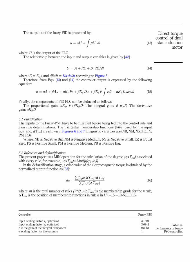
The output u of the fuzzy PID is presented by:
u ¼ αU þZ
βU dt (13)
where: U is the output of the FLC.The relationship between the input and output variables is given by [42]:
U ¼ Aþ PE þ D dE=dt (14)
where: E 5 Ke.e and dE/dt 5 Kd.de/dt according to Figure 5.Therefore, from Eqs. (13) and (14) the controller output is expressed by the following
equation:
u ¼ αAþ βA:t þ αKe:Peþ βKd:D:eþ βKe:P
Zedt þ αKd:D:de=dt (15)
Finally, the components of PID-FLC can be deducted as follows:The proportional gain: αKe. PþβKd.D; The integral gain: β Ke.P; The derivative
gain: αKd.D.
5.1 FuzzificationThe inputs to the Fuzzy-PSO have to be fuzzified before being fed into the control rule andgain rule determinations. The triangular membership functions (MFs) used for the input(e, ec and, ΔTem) are shown in Figures 6 and 7. Linguistic variables are (NB, NM, NS, ZE, PS,PM, PB).
Where: NB is Negative Big, NM is Negative Medium, NS is Negative Small, EZ is EqualZero, PS is Positive Small, PM is Positive Medium, PB is Positive Big.
5.2 Inference and defuzzificationThe present paper uses MIN operation for the calculation of the degree m(ΔTem) associatedwith every rule, for example, m(ΔTem)5Min[m(e),m(ec)].
In the defuzzification stage, a crisp value of the electromagnetic torque is obtained by thenormalized output function as [33]:
du ¼Pm
j¼1μðΔTemjÞΔTemjPm
j¼1μðΔTemjÞ (16)
where: m is the total number of rules (7*7), m(ΔTem) is the membership grade for the n rule,ΔTem is the position of membership functions in rule n in U (�15,�10,-5,0,10,15).
Controller Fuzzy-PSO
Input scaling factor ke optimized 3.1604Input scaling factor kd optimized 3.6741β is the gain of the integral component 0.8081α scaling factor for the output u 1
Table 4.Performance of fuzzy-
PSO controller.
Direct torquecontrol of dualstar induction
motor
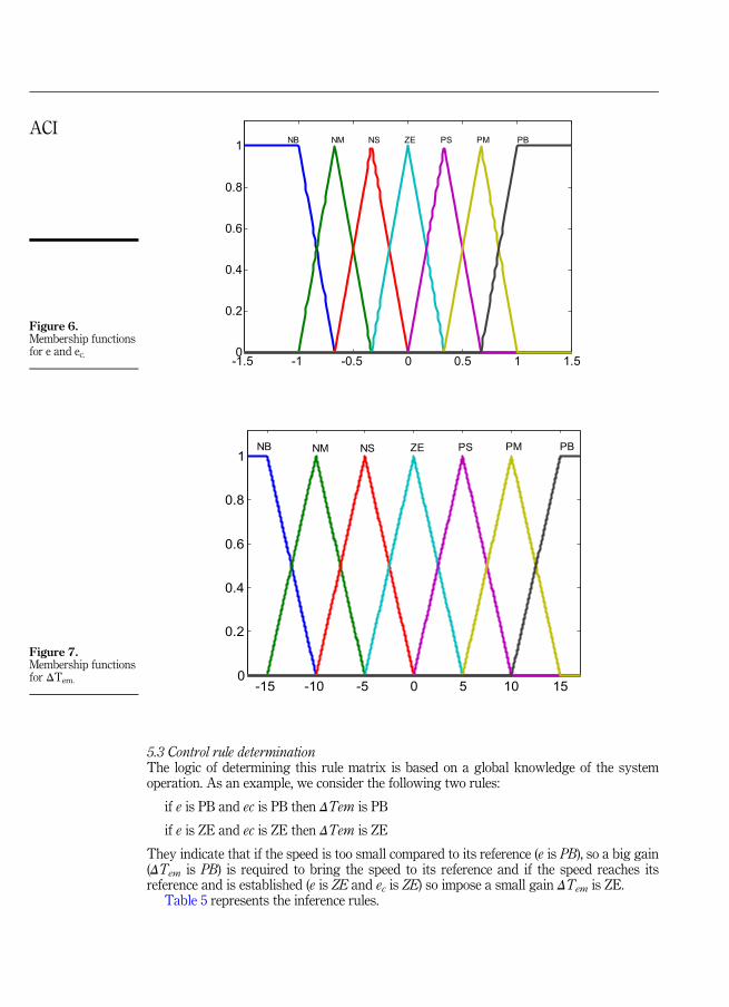
5.3 Control rule determinationThe logic of determining this rule matrix is based on a global knowledge of the systemoperation. As an example, we consider the following two rules:
if e is PB and ec is PB then ΔTem is PB
if e is ZE and ec is ZE then ΔTem is ZE
They indicate that if the speed is too small compared to its reference (e is PB), so a big gain(ΔTem is PB) is required to bring the speed to its reference and if the speed reaches itsreference and is established (e is ZE and ec is ZE) so impose a small gain ΔTem is ZE.
Table 5 represents the inference rules.
-15 -10 -5 0 5 10 150
0.2
0.4
0.6
0.8
1ZE PS PM PBNSNMNB
-1.5 -1 -0.5 0 0.5 1 1.50
0.2
0.4
0.6
0.8
1 ZE PS PM PBNSNMNB
Figure 7.Membership functionsfor ΔTem.
Figure 6.Membership functionsfor e and ec.
ACI
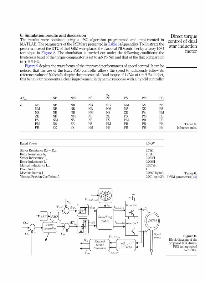
6. Simulation results and discussionThe results were obtained using a PSO algorithm programmed and implemented inMATLAB. The parameters of the DSIM are presented in Table 6 (Appendix). To illustrate theperformances of the DTC of the DSIMwe replaced the classical PID controller by a fuzzy-PSOtechnique in Figure 8. The simulation is carried out under the following conditions: thehysteresis band of the torque comparator is set to ±0.25 Nm and that of the flux comparatorto ± 0.5 Wb.
Figure 9 depicts the waveforms of the improved performances of speed control. It can benoticed that the use of the fuzzy-PSO controller allows the speed to judiciously follow itsreference value of 100 rad/s despite the presence of a load torque of 14Nm at t5 0.6 s. In fact,this behaviour represents a clear improvement in dynamic response with a hybrid controller
Rated Power 4.5KW
Stator Resistance Rs15 Rs2 3.72URotor Resistance Rr 2.12UStator Inductance Ls 0.022HRotor Inductance Lr 0.006HMutual Inductance Lm 0.3672HPole Pairs P 1Machine Inertia J 0.0662 kg.m2Viscous Friction Coefficient fr 0.001 kg.m2/s
Ωref
Speed
sensor
3
3
(a,b,c,1)ss
Flux and Torque
Estimation
s
DSIM Switching
Table (ccpl)
1
0 +
- (cflx) sref
+-
Inverter2
s
( , ,1,2)sI
sψˆ ( , ,1,2)s
(a,b,c,2)ss
Inverter1
Vdc
( , ,1,2)sV
a,b,c
+ -
Fuzzy controller
PSO IAE
1 2 3
4 5 6
sψ̂
1
-1
0
Ωr emT̂
emT
ˆem Τ
emT
ecΔTem NB NM NS ZE PS PM PB
E NB NB NB NB NB NM NS ZENM NB NB NB NM NS ZE PSNS NB NB NM NS ZE PS PMZE NB NM NS ZE PS PM PBPS NM NS ZE PS PM PB PBPM NS ZE PS PM PB PB PBPB ZE PS PM PB PB PB PB
Table 6.DSIM parameters [12].
Figure 8.Block diagram of theproposed DTC-fuzzy-
PSO tuning speedcontroller.
Table 5.Inference rules.
Direct torquecontrol of dualstar induction
motor
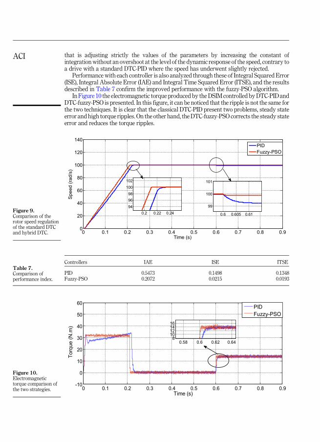
that is adjusting strictly the values of the parameters by increasing the constant ofintegrationwithout an overshoot at the level of the dynamic response of the speed, contrary toa drive with a standard DTC-PID where the speed has underwent slightly rejected.
Performance with each controller is also analyzed through these of Integral Squared Error(ISE), Integral Absolute Error (IAE) and Integral Time Squared Error (ITSE), and the resultsdescribed in Table 7 confirm the improved performance with the fuzzy-PSO algorithm.
In Figure 10 the electromagnetic torque produced by theDSIM controlled byDTC-PID andDTC-fuzzy-PSO is presented. In this figure, it can be noticed that the ripple is not the same forthe two techniques. It is clear that the classical DTC-PID present two problems, steady stateerror and high torque ripples. On the other hand, the DTC-fuzzy-PSO corrects the steady stateerror and reduces the torque ripples.
Controllers IAE ISE ITSE
PID 0.5473 0.1498 0.1348Fuzzy-PSO 0.2072 0.0215 0.0193
0 0.1 0.2 0.3 0.4 0.5 0.6 0.7 0.8 0.9-10
0
10
20
30
40
50
60
Time (s)
Tor
que
(N.m
)
PIDFuzzy-PSO
0.58 0.6 0.62 0.648
10121416
0 0.1 0.2 0.3 0.4 0.5 0.6 0.7 0.8 0.90
20
40
60
80
100
120
140
Time (s)
Spee
d (ra
d/s)
0.2 0.22 0.24949698
100102
0.6 0.605 0.61
99
100
101
PIDFuzzy-PSO
Table 7.Comparison ofperformance index.
Figure 10.Electromagnetictorque comparison ofthe two strategies.
Figure 9.Comparison of therotor speed regulationof the standard DTCand hybrid DTC.
ACI
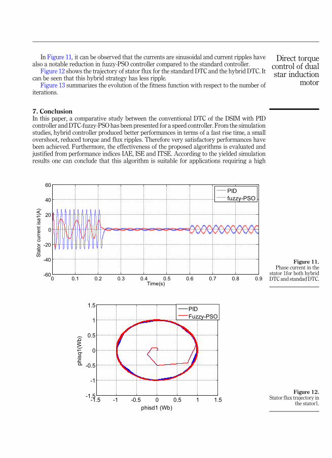
In Figure 11, it can be observed that the currents are sinusoidal and current ripples havealso a notable reduction in fuzzy-PSO controller compared to the standard controller.
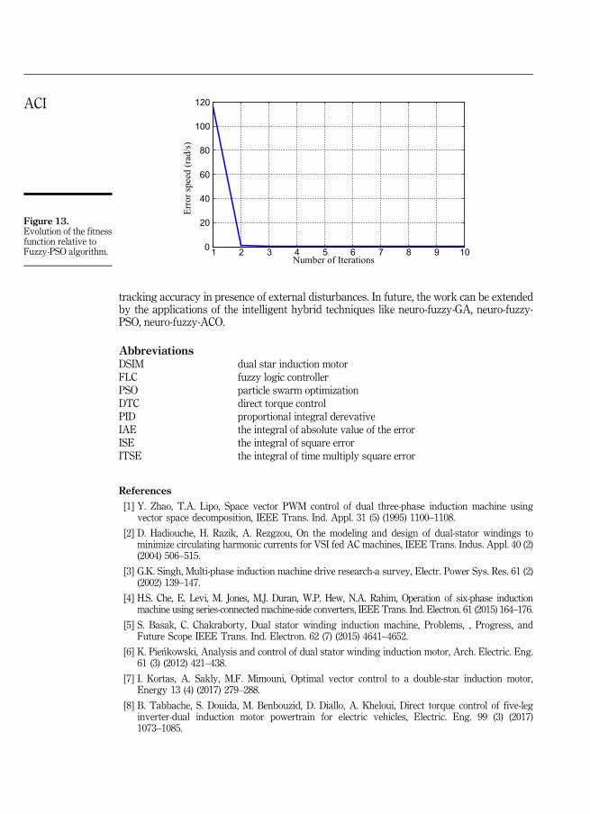
Figure 12 shows the trajectory of stator flux for the standard DTC and the hybrid DTC. Itcan be seen that this hybrid strategy has less ripple.
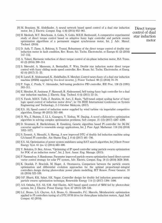
Figure 13 summarizes the evolution of the fitness function with respect to the number ofiterations.
7. ConclusionIn this paper, a comparative study between the conventional DTC of the DSIM with PIDcontroller andDTC-fuzzy-PSO has been presented for a speed controller. From the simulationstudies, hybrid controller produced better performances in terms of a fast rise time, a smallovershoot, reduced torque and flux ripples. Therefore very satisfactory performances havebeen achieved. Furthermore, the effectiveness of the proposed algorithms is evaluated andjustified from performance indices IAE, ISE and ITSE. According to the yielded simulationresults one can conclude that this algorithm is suitable for applications requiring a high
-1.5 -1 -0.5 0 0.5 1 1.5-1.5
-1
-0.5
0
0.5
1
1.5
phisd1 (Wb)
phis
q1(W
b)
PIDFuzzy-PSO
0 0.1 0.2 0.3 0.4 0.5 0.6 0.7 0.8 0.9-60
-40
-20
0
20
40
60
Time(s)
Stat
or c
urre
nt is
a1(A
)
PIDfuzzy-PSO
Figure 12.Stator flux trajectory in
the stator1.
Figure 11.Phase current in the
stator 1for both hybridDTC and standadDTC.
Direct torquecontrol of dualstar induction
motor
tracking accuracy in presence of external disturbances. In future, the work can be extendedby the applications of the intelligent hybrid techniques like neuro-fuzzy-GA, neuro-fuzzy-PSO, neuro-fuzzy-ACO.
AbbreviationsDSIM dual star induction motorFLC fuzzy logic controllerPSO particle swarm optimizationDTC direct torque controlPID proportional integral derevativeIAE the integral of absolute value of the errorISE the integral of square errorITSE the integral of time multiply square error
References
[1] Y. Zhao, T.A. Lipo, Space vector PWM control of dual three-phase induction machine usingvector space decomposition, IEEE Trans. Ind. Appl. 31 (5) (1995) 1100–1108.
[2] D. Hadiouche, H. Razik, A. Rezgzou, On the modeling and design of dual-stator windings tominimize circulating harmonic currents for VSI fed AC machines, IEEE Trans. Indus. Appl. 40 (2)(2004) 506–515.
[3] G.K. Singh, Multi-phase induction machine drive research-a survey, Electr. Power Sys. Res. 61 (2)(2002) 139–147.
[4] H.S. Che, E. Levi, M. Jones, M.J. Duran, W.P. Hew, N.A. Rahim, Operation of six-phase inductionmachine using series-connected machine-side converters, IEEE Trans. Ind. Electron. 61 (2015) 164–176.
[5] S. Basak, C. Chakraborty, Dual stator winding induction machine, Problems, , Progress, andFuture Scope IEEE Trans. Ind. Electron. 62 (7) (2015) 4641–4652.
[6] K. Pie�nkowski, Analysis and control of dual stator winding induction motor, Arch. Electric. Eng.61 (3) (2012) 421–438.
[7] I. Kortas, A. Sakly, M.F. Mimouni, Optimal vector control to a double-star induction motor,Energy 13 (4) (2017) 279–288.
[8] B. Tabbache, S. Douida, M. Benbouzid, D. Diallo, A. Kheloui, Direct torque control of five-leginverter-dual induction motor powertrain for electric vehicles, Electric. Eng. 99 (3) (2017)1073–1085.
1 2 3 4 5 6 7 8 9 100
20
40
60
80
100
120
Err
or
spee
d (
rad/s
)
Number of Iterations
Figure 13.Evolution of the fitnessfunction relative toFuzzy-PSO algorithm.
ACI
[9] M. Bouziane, M. Abdelkader, A neural network based speed control of a dual star inductionmotor, Int. J. Electric. Comput. Eng. 4 (6) (2014) 952–961.
[10] H. Mesloub, M.T. Benchouia, A. Gol�ea, N. Gol�ea, M.E.H. Benbouzid, A comparative experimentalstudy of direct torque control based on adaptive fuzzy logic controller and particle swarmoptimization algorithms of a permanent magnet synchronous motor, Int. J. Adv. Manuf.Technol. (2016).
[11] D. Azib, T. Ziane, A. Rekioua, S. Tounzi, Robustness of the direct torque control of double starinduction motor in fault condition, Rev. Roum. Sci. Techn. �Electrotechn. et �Energn 61 (2) (2016)147–152.
[12] A. Taheri, Harmonic reduction of direct torque control of six-phase induction motor, ISA Trans.63 (2) (2016) 299–314.
[13] S. Meroufel, A. Massoum, A. Bentaallah, P. Wira, Double star induction motor direct torquecontrol with fuzzy sliding mode speed controller, Rev. Roum. Sci. Techn. Electrotechn. et Energ.62 (4) (2017) 31–35.
[14] B. Larafi, R. Abdessemed, K. Abdelhalim, E. Merabet, Control neuro-fuzzy of a dual star inductionmachine (DSIM) supplied by five-level inverter, J. Power Technol. 98 (1) (2018) 70–79.
[15] P. Vega, C. Prada, V. Aleixander, Self-tuning predictive PID controller, IEE Proc. 138 (3) (1991)303–311.
[16] E. Merabet, H. Amimeur, F. Hamoudi, R. Abdessemed, Self tuning fuzzy logic controller for a dualstar induction machine, J. Electric. Eng. Technol. 6 (4) (2011) 33–54.
[17] N. Farah, M.H.N. Talib, Z. Ibrahim, M. Azri, Z. Rasin, “Self-tuned output scaling factor of fuzzylogic speed control of induction motor drive”, in: 7th IEEE International Conference on SystemEngineering and Technology, 2–3 October Malaysia, (2017).
[18] E.S. Ali, Speed control of induction motor supplied by wind turbine via imperialist competitivealgorithm, Energy 89 (2015) 593–600.
[19] D. Wu, Z. Huimin, Z. LI, L. Guangyu, Y. Xinhua, W. Daqing, A novel collaborative optimizationalgorithm in solving complex optimization problems, Soft comput. 21 (15) (2017) 4387–4398.
[20] D. Sivamani, R. Harikrishnan, R. Essakiraj, Genetic algorithm based PI controller for DC-DCconverter applied to renewable energy applications, Int. J. Pure Appl. Mathemat. 118 (16) (2018)1053–1071.
[21] S. Zemmit, A. Messalti, A. Harrag, A new improved DTC of doubly fed induction machine usingGA-based PI controller, Ain Shams Eng. J. 8 (4) (2017) 481–706.
[22] E.S. Ali, Optimization of power system stabilizers using BAT search algorithm, Int J Electr PowerEnergy Syst. 61 (no. C) (2014) 683–690.
[23] Y. Bekakra, D. Ben, Attous, “Optimizing of IP speed controller using particle swarm optimizationfor FOC of an induction motor”, Int. J. Syst. Assur. Eng. Manage. (2015).
[24] P. Nammalvar, S. Ramkumar, Parameter improved particle swarm optimization based direct-currentvector control strategy for solar PV system, Adv. Electric. Comput. Eng. 18 (1) (2018) 3628–3648.
[25] K. Dezelak, P. Bracinik, M. Hoger, A. Otcenasova, Comparison between the particle swarmoptimisation and differential evolution approaches for the optimal proportional–integralcontrollers design during photovoltaic power plants modelling, IET Renew. Power Generat. 10(4) (2016) 522–530.
[26] O.P. Bharti, R.K. Saket, S.K. Nagar, Controller design for doubly fed induction generator usingparticle swarm optimization technique, Renewable Energy 114 (1) (2017) 1394–1406.
[27] A.S. Oshaba, E.S. Ali, S.M. Abd Elazim, ACO based speed control of SRM fed by photovoltaicsystem, Int. J. Electric. Power Energy Syst. 67 (2015) 529–536.
[28] L.C. Bruno, L.G. Clayton, A.A. Bruno, G. Alessandro, F.C. Marcelo, Metaheuristic optimizationapplied to PI controllers tuning of a DTC-SVM drive for three-phase induction motors, Appl. SoftComput. 62 (2018).
Direct torquecontrol of dualstar induction
motor
[29] H. Garg, A hybrid PSO-GA algorithm for constrained optimization problems, Appl. Mathemat.Comput. 274 (2) (2016) 1292–1305.
[30] A. Gacem, D. Benattous, Hybrid GA–PSO for optimal placement of static VAR compensators inpower system, Int. J. Syst. Assur. Eng. Manage. (2015).
[31] M. Mareli, B. Twala, An adaptive Cuckoo search algorithm for optimisation, Appl. Comput.Informat. 14 (2) (2018) 107–115.
[32] R. Eberhart, J. Kennedy, A new optimizer using particles warm theory”, Proceedings of the SixthInternational Symposium on Micro Machine and Human Science, Japan (1995) 39–43.
[33] Z. Tir, O.P. Malik, A.M. Eltamaly, Fuzzy logic based speed control of indirect field orientedcontrolled double star induction motors“ connected in parallel to a single six-phase inverter,Electric Power Syst. Res. 134 (1) (2016) 126–133.
[34] J.P. Yu, P. Shi, W. Dong, C. Lin, Command filtering-based fuzzy control for nonlinear systemswith saturation input, IEEE Trans. Cybernet. 47 (9) (2017).
[35] J.P. Yu, B. Chen, H. Yu, C. Lin, L. Zhao, Neural networks-based command filtering control ofnonlinear systems with uncertain disturbance, Informat. Sci. 426 (2018) 50–60.
[36] J.P. Yu, P. Shi, W. Dong, C. Lin, Adaptive fuzzy control of nonlinear systems with unknown deadzones based on command filtering, IEEE Trans. Fuzzy Syst. 26 (1) (2018).
[37] Z. Zhou, J.P. Yu, H. Yu, C. Lin, Neural network-based discrete-time command filtered adaptiveposition tracking control for induction motors via backstepping, Neurocomputing 260 (2017) 203–210.
[38] J. Huang, J. Wang, H. Fang, An anti-windup self-tuning fuzzy PID controller for speed control ofbrushless DC motor, , Automatika, J. Control Measure. 58 (3) (2018) 321–335.
[39] O. Karasakal, E. Yesil, M. Guzelkaya, I. Eksin, Implementation of a new self-tuning fuzzy PIDcontroller on PLC, Turk. J. Elec. Eng. 13 (2) (2005).
[40] I. Takahashi, T. Noguchi, A new quick-response and high-efficiency control strategy of aninduction motor, IEEE Trans. Indust. Appl. 22 (5) (1986) 820–827.
[41] S. Kavita, C. Varsha, S. Harish, C.B. Jagdish, Fitness based particle swarm optimization, Int. J.Syst. Assur. Eng. Manage. 6 (3) (2015) 319–329.
[42] W.Z. Qiao, M. Mizumoto, PID type fuzzy controller and parameters adaptive method, Fuzzy SetsSyst. 78 (2) (1996) 23–35.
AppendixSee.
Corresponding authorSebti Belkacem can be contacted at: [email protected]
For instructions on how to order reprints of this article, please visit our website:www.emeraldgrouppublishing.com/licensing/reprints.htmOr contact us for further details: [email protected]
ACI