Direct nanoimprinting of metal oxides by in situ thermal co-polymerization of their methacrylates
9
Direct nanoimprinting of metal oxides by in situ thermal co-polymerization of their methacrylates† Ramakrishnan Ganesan, * a Su Hui Lim, a M. S. M. Saifullah, * a Hazrat Hussain, a John X. Q. Kwok, b Ryan L. X. Tse, b Htoo A. P. Bo b and Hong Yee Low a Received 26th November 2010, Accepted 21st January 2011 DOI: 10.1039/c0jm04105j The use of polymerization to solidify, strengthen and imprint liquid organic materials is the basis of ultraviolet (UV) nanoimprint lithography. In spite of these advantages, the use of polymerization to pattern materials in thermal nanoimprint lithography is almost non-existent. In this study, we demonstrate a facile and general method to directly imprint a host of unary metal oxides (Fe 2 O 3 , ZrO 2 , TiO 2 , Nb 2 O 5 and Ta 2 O 5 ) at a very high resolution via in situ thermal free radical co-polymerization of various metal methacrylates in the presence of cross-linker ethylene glycol dimethacrylate using a silicon mold. Polymerization during nanoimprinting rigidly shapes the patterns, traps the metal atoms, reduces the surface energy and strengthens the structures, thereby giving 100% yield after demolding. It was found that the higher oxidation state of metal resulted in excessive cracking of imprinted structures. This could be due to a higher degree of cross-linking of the precursor leading to shrinkage-related stress. Optimization of the resin composition by partially replacing ethylene glycol dimethacrylate with methyl methacrylate alleviated this problem. Heat-treatment of the imprinted structures resulted in the loss of organics, their subsequent shrinkage and converted the patterns to their corresponding metal oxides with line-widths as small as 25 nm. 1. Introduction With the inherent advantages of low-cost and high-throughput, nanoimprint lithography is emerging as an alternative patterning technique to optical lithography that not only enables patterning of resists, but also is capable of imprinting functional device structures, which can lead to a wide range of applications in electronics, photonics, data storage and biology. 1 Nano- imprinting involves pressing of a mold that contains surface relief features onto a film on a substrate at a controlled temperature and pressure. For obtaining a good imprint, it is desirable to have a film with low viscosity and good adhesion on the surface. The common polymeric materials used in nanoimprint lithography are thermoplastics, thermosets and UV-curable polymers. In order to directly imprint functional materials such as oxides, sol– gel films and metal–organic materials are being increasingly used. 2–14 Sol–gel techniques with their low-temperature characteristics, good film quality, and as an economical way to obtain engi- neered ceramics have attracted great deal of attention in patterning technologies. Alkoxide-based sol–gel chemistry has been extensively used to pattern oxides using optical litho- graphy, 15–21 electron beam nanolithography, 21–27 electro- hydrodynamic lithography 28 and, more recently, it has been embraced by nanoimprinting as well. 2,5–7 However, direct imprinting of oxides via the sol–gel route faces two major chal- lenges. Firstly, due to their high surface energy, the sol–gel imprinting requires a good mold release system preferably con- taining long chain silanes and, secondly, the solvent in the sol–gel film, which helps to ‘soften’ it for imprint process, gets trapped in the imprinted structures resulting in poor demolding and incomplete filling of the precursor material inside the mold. These problems have been partly alleviated by using soft molds with low surface energies such as polydimethylsiloxane (PDMS), 4–6,8–10 and perfluoropolyether (PFPE) 7 to imprint oxides. Soft molds absorb the solvent in the films, thus giving the imprint its strength to withstand demolding forces and conse- quently reducing the severity of temperature requirement as required in the case of a silicon mold. 2 However, soft molds are amenable to deformation, especially when sub-100 nm features are desired. Polymerization of liquid resist is used extensively in UV nanoimprint lithography to imprint liquid organic materials as a Institute of Materials Research and Engineering, A*STAR (Agency for Science Technology and Research), 3 Research Link, Singapore, 117602, Republic of Singapore. E-mail: [email protected]; [email protected] b NUS High School of Mathematics and Science, 20 Clementi Avenue 1, Singapore, 129957, Republic of Singapore † Electronic supplementary information (ESI) available. See DOI: 10.1039/c0jm04105j 4484 | J. Mater. Chem., 2011, 21, 4484–4492 This journal is ª The Royal Society of Chemistry 2011 Dynamic Article Links C < Journal of Materials Chemistry Cite this: J. Mater. Chem., 2011, 21, 4484 www.rsc.org/materials PAPER Published on 15 February 2011. Downloaded by University of California - Irvine on 25/10/2014 21:29:04. View Article Online / Journal Homepage / Table of Contents for this issue
Transcript of Direct nanoimprinting of metal oxides by in situ thermal co-polymerization of their methacrylates

Dynamic Article LinksC<Journal ofMaterials Chemistry
Cite this: J. Mater. Chem., 2011, 21, 4484
www.rsc.org/materials PAPER
Publ
ishe
d on
15
Febr
uary
201
1. D
ownl
oade
d by
Uni
vers
ity o
f C
alif
orni
a -
Irvi
ne o
n 25
/10/
2014
21:
29:0
4.
View Article Online / Journal Homepage / Table of Contents for this issue
Direct nanoimprinting of metal oxides by in situ thermal co-polymerizationof their methacrylates†
Ramakrishnan Ganesan,*a Su Hui Lim,a M. S. M. Saifullah,*a Hazrat Hussain,a John X. Q. Kwok,b
Ryan L. X. Tse,b Htoo A. P. Bob and Hong Yee Lowa
Received 26th November 2010, Accepted 21st January 2011
DOI: 10.1039/c0jm04105j
The use of polymerization to solidify, strengthen and imprint liquid organic materials is the basis of
ultraviolet (UV) nanoimprint lithography. In spite of these advantages, the use of polymerization to
pattern materials in thermal nanoimprint lithography is almost non-existent. In this study, we
demonstrate a facile and general method to directly imprint a host of unary metal oxides (Fe2O3, ZrO2,
TiO2, Nb2O5 and Ta2O5) at a very high resolution via in situ thermal free radical co-polymerization of
various metal methacrylates in the presence of cross-linker ethylene glycol dimethacrylate using
a silicon mold. Polymerization during nanoimprinting rigidly shapes the patterns, traps the metal
atoms, reduces the surface energy and strengthens the structures, thereby giving �100% yield after
demolding. It was found that the higher oxidation state of metal resulted in excessive cracking of
imprinted structures. This could be due to a higher degree of cross-linking of the precursor leading to
shrinkage-related stress. Optimization of the resin composition by partially replacing ethylene glycol
dimethacrylate with methyl methacrylate alleviated this problem. Heat-treatment of the imprinted
structures resulted in the loss of organics, their subsequent shrinkage and converted the patterns to their
corresponding metal oxides with line-widths as small as 25 nm.
1. Introduction
With the inherent advantages of low-cost and high-throughput,
nanoimprint lithography is emerging as an alternative patterning
technique to optical lithography that not only enables patterning
of resists, but also is capable of imprinting functional device
structures, which can lead to a wide range of applications in
electronics, photonics, data storage and biology.1 Nano-
imprinting involves pressing of a mold that contains surface relief
features onto a film on a substrate at a controlled temperature
and pressure. For obtaining a good imprint, it is desirable to have
a film with low viscosity and good adhesion on the surface. The
common polymeric materials used in nanoimprint lithography
are thermoplastics, thermosets and UV-curable polymers. In
order to directly imprint functional materials such as oxides, sol–
gel films and metal–organic materials are being increasingly
used.2–14
aInstitute of Materials Research and Engineering, A*STAR (Agency forScience Technology and Research), 3 Research Link, Singapore, 117602,Republic of Singapore. E-mail: [email protected];[email protected] High School of Mathematics and Science, 20 Clementi Avenue 1,Singapore, 129957, Republic of Singapore
† Electronic supplementary information (ESI) available. See DOI:10.1039/c0jm04105j
4484 | J. Mater. Chem., 2011, 21, 4484–4492
Sol–gel techniques with their low-temperature characteristics,
good film quality, and as an economical way to obtain engi-
neered ceramics have attracted great deal of attention in
patterning technologies. Alkoxide-based sol–gel chemistry has
been extensively used to pattern oxides using optical litho-
graphy,15–21 electron beam nanolithography,21–27 electro-
hydrodynamic lithography28 and, more recently, it has been
embraced by nanoimprinting as well.2,5–7 However, direct
imprinting of oxides via the sol–gel route faces two major chal-
lenges. Firstly, due to their high surface energy, the sol–gel
imprinting requires a good mold release system preferably con-
taining long chain silanes and, secondly, the solvent in the sol–gel
film, which helps to ‘soften’ it for imprint process, gets trapped in
the imprinted structures resulting in poor demolding and
incomplete filling of the precursor material inside the mold.
These problems have been partly alleviated by using soft molds
with low surface energies such as polydimethylsiloxane
(PDMS),4–6,8–10 and perfluoropolyether (PFPE)7 to imprint
oxides. Soft molds absorb the solvent in the films, thus giving the
imprint its strength to withstand demolding forces and conse-
quently reducing the severity of temperature requirement as
required in the case of a silicon mold.2 However, soft molds are
amenable to deformation, especially when sub-100 nm features
are desired.
Polymerization of liquid resist is used extensively in UV
nanoimprint lithography to imprint liquid organic materials as
This journal is ª The Royal Society of Chemistry 2011

Publ
ishe
d on
15
Febr
uary
201
1. D
ownl
oade
d by
Uni
vers
ity o
f C
alif
orni
a -
Irvi
ne o
n 25
/10/
2014
21:
29:0
4.
View Article Online
well as oxides.1,4,13 The liquid resist used for UV imprinting has
low viscosity, enhances wider resist redistribution and flow
during the process, giving rise to printing uniformity and in some
cases almost a near-zero residual layer at the bottom of the
pattern. In spite of these advantages of liquid resists, there is
hardly any work in using them to pattern materials using thermal
nanoimprint lithography.29,30 To fill this gap, in this work we
propose to combine alkoxide-based chemistry with methacrylate
chemistry to form liquid metal methacrylate resins capable of
undergoing in situ thermal free radical co-polymerization to
directly pattern oxides using silicon molds. Our preliminary work
on imprinting of TiO2 via this route has shown considerable
amount of promise.14 In this work we demonstrate a facile and
general method to directly imprint a host of unary metal oxides,
viz., Fe2O3, ZrO2, TiO2, Nb2O5 and Ta2O5 from their respective
metal methacrylates. Except for iron methacrylate, all others
were prepared by reacting their respective metal alkoxides with
methacrylic acid. Our approach incorporates the benefits of
a rigid mold and liquid precursor to achieve very high resolution
over areas >1 cm� 1 cm but at a lower temperature and pressure
to obtain yields of almost 100% after imprinting. It was observed
that the quality of imprint was dependent on the oxidation state
of the metal atom in metal methacrylate resins. Therefore, in this
paper we will only discuss the imprinting of representative resins
corresponding to the oxidation states +3 (Fe), +4 (Zr), and +5
(Ta).
2. Experimental details
Materials
Aluminium(III) tert-butoxide (97%, Aldrich), yttrium(III) n-but-
oxide (99.9+%, 0.5 M in toluene, Sigma Aldrich), zirconium(IV)
n-butoxide (80 wt% in 1-butanol, Sigma Aldrich), titanium(IV)
n-butoxide (97%, Sigma Aldrich), hafnium(IV) tert-butoxide
(99.9%, Alfa Aesar), tin(IV) tert-butoxide (99.99%, Aldrich),
niobium(V) ethoxide (99.5%, Sigma Aldrich), vanadium(V) trii-
sopropoxide oxide (95–99%, Alfa Aesar), tantalum(V) n-but-
oxide (98%, Sigma Aldrich), iron(III) chloride (anhydrous, 98%,
Alfa Aesar) and sodium methacrylate (98%, Sigma Aldrich)
were used without purification.
Ethylene glycol dimethacrylate (EDMA), methacrylic acid
(MAA) and methyl methacrylate (MMA) were purchased from
Sigma Aldrich, and were used after removing the stabilizer using
an alumina column. Azobisisobutyronitrile (AIBN) was purified
by recrystallization in methanol. 1H,1H,2H,2H-Per-
fluorodecyltrichlorosilane (96%, Alfa Aesar) was used as
received.
This journal is ª The Royal Society of Chemistry 2011
Preparation of metal methacrylates
Iron(III) methacrylate was prepared by double decomposition of
iron(III) chloride and sodium methacrylate in an aqueous
medium. The product formed was deep brown in colour. It was
washed a few times in water and dried overnight in a vacuum
oven. The dried product was purified by dissolving it in
dichloromethane and the solution was filtered to remove any
unreacted material. Iron(III) methacrylate was obtained by
removing the solvent under reduced pressure in a rotary evapo-
rator.
Rest of the metal methacrylate derivatives were prepared
inside a glove box (<5% relative humidity) by mixing the corre-
sponding metal alkoxides with stoichiometric quantity of MAA
needed to remove all the alkoxy groups. Instantaneous charac-
teristic colour change was observed, indicating formation of the
metal methacrylates.
Resin formulation
Resin formulation of each metal methacrylate was prepared by
mixing it with a known amount of EDMA and 2 wt% of AIBN,
the latter corresponding to the total amount of EDMA and
MAA. All the formulations were purged with argon gas for 2–3
minutes to remove dissolved oxygen. Hereafter, the formulations
will be referred to as their corresponding metal oxide resins. For
example, zirconium methacrylate, EDMA and AIBN mixture
will be designated as ZrO2 resin.
Imprint lithography
Silicon substrates and silicon molds were cleaned using hot
piranha solution (3 : 7 by volume of 30% H2O2 and H2SO4.
Caution: Piranha solution reacts violently with most organic
materials and must be handled with extreme care!) for 2 hours,
followed by washing with deionized water and blow drying using
a nitrogen gun. The molds were silanized with 1H,1H,2H,2H-
perfluorodecyltrichlorosilane for 5 hours to decrease their
surface energy, which in turn facilitates a clean demolding after
imprinting.
The metal oxide resins were spin-coated onto the pre-cleaned
silicon substrates at two spin speeds, 3000 and 6000 rpm, in order
to control the film thickness. Imprint lithography was carried out
in an Obducat imprinter (Obducat, Sweden). Imprinting condi-
tions for various resins were determined using differential scan-
ning calorimetry (DSC, TA Instruments Q100). A Nicolet� 6700
Fourier transform infrared (FTIR) spectroscope was used to
analyze the change in structure of the resin during polymeriza-
tion. Thermogravimetric analysis (TGA, TA Instruments Q500)
J. Mater. Chem., 2011, 21, 4484–4492 | 4485

Publ
ishe
d on
15
Febr
uary
201
1. D
ownl
oade
d by
Uni
vers
ity o
f C
alif
orni
a -
Irvi
ne o
n 25
/10/
2014
21:
29:0
4.
View Article Online
was used to determine the degradation temperature of organic
constituents and formation of oxide. This information was used
for the heat-treatment of imprinted samples in a furnace heated
at the rate of 10 �C min�1.
Characterization of imprints
Scanning electron and atomic force microscopies were used to
study the topography and morphology of imprinted features
before and after heat-treatment. High resolution images of as-
imprinted as well as heat-treated imprinted structures were
acquired using a JEOL JSM6700F field-emission scanning elec-
tron microscope (FE-SEM). For X-ray diffraction (XRD)
analysis, imprinting of metal oxide resins was done using a blank
silicon substrate as the mold, followed by the heat-treatment at
different temperatures. A Bruker D8 General Area Detector
Diffraction System (GADDS) equipped with a Cu-Ka source
was used to do XRD analysis of heat-treated metal oxide films.
3. Results and discussion
Metal methacrylates are either insoluble or sparingly soluble in
organic solvents. Earlier studies have suggested that when they
are formed by reacting stoichiometric amounts of their respective
alkoxides with MAA, their solubility seems to increase enor-
mously and the product formed is a clear solution.14,31 Metal
alkoxides are strong bases and may rapidly react with MAA, an
acidic monomer, and are neutralized. At [MAA]/[Mx+] ¼ 1 the
following reaction proceeds rapidly, and an Mx+ complex and
alcohol are generated.
M(OR)x + MAA / M(OR)x�1(MA) + ROH
R and MA denote alkyl group and deprotonated MAA, i.e.,
methacrylate, respectively. Furthermore, this reaction is
exothermic and is accompanied by a colour change of the solu-
tion. Complexes of the metal ions with methacrylate are gener-
ated with alcohols as byproducts.31 Table 1 gives
a comprehensive listing of reaction between liquid metal alk-
oxides and MAA, and the potential usefulness of the obtained
product in direct imprinting of oxides. It was found that
alkoxides of aluminium, yttrium, tin, hafnium and vanadium
either precipitated or formed gels when reacted with MAA. On
the other hand, reaction between MAA and alkoxides of
Table 1 Imprintability of various metal methacrylates formed by reacting th
AlkoxideColour chacid addi
Aluminium(III) tert-butoxide TransparYttrium(III) n-butoxide TransluceTitanium(IV) n-butoxide Dark broTin(IV) tert-butoxide White prZirconium(IV) n-butoxide Pale yelloHafnium(IV) tert-butoxide Pinkish, b
minuteNiobium(V) ethoxide YellowTantalum(V) n-butoxide Faint yelVanadium(V) triisopropoxide oxide Faint yel
when e
4486 | J. Mater. Chem., 2011, 21, 4484–4492
titanium, zirconium, niobium and tantalum gave clear solutions.
These liquid solutions were found to be very stable, with no
precipitate generated during several weeks of storage. They were
chosen for further studies involving direct imprinting of oxides.
As iron methacrylate was difficult to prepare via the reaction of
its alkoxide with MAA, it was made as described in the earlier
section.
For high resolution nanoimprinting, low viscosity liquid
precursors are preferable since they fill into the mold cavities
easily upon applied pressure and enable printing uniformity. In
this work, nanoimprinting was performed in a two-step process
by placing the mold on a thin film of metal methacrylate con-
taining metal oxide resin spin-coated onto a silicon substrate: (i)
applying pressure to fill the monomers into the mold cavities, and
(ii) heating the set-up to the polymerization temperature, whilst
the applied pressure was kept constant. After imprinting, the
assembly was cooled down to 65 �C before releasing the pressure,
followed by demolding. We have successfully applied this
method to the resins of five different metal oxides of iron, tita-
nium, zirconium, niobium and tantalum, and demonstrated the
ability of imprinting their oxides on a sub-50 nm scale. Fig. 1
depicts the steps involved in direct nanoimprint lithography of
oxides. It was observed that the group of metal oxide resins
containing same oxidation state of metal behaves in a similar
way. Therefore, we will only discuss the imprinting of represen-
tative metal methacrylates corresponding to the oxidation states
of +3 (Fe), +4 (Zr), and +5 (Ta).
Fe2O3 resin
Iron was chosen as a trivalent candidate and its methacrylate
derivative, iron methacrylate, was synthesized from double
decomposition of iron(III) chloride and sodium methacrylate in
an aqueous medium. The FTIR spectrum of the final product
resembled that of sodium methacrylate, since the organic part
remained unchanged. Iron methacrylate (3 mmol) was dissolved
in a 1 : 1 mixture of iso-propanol–butanol (1 ml). To this,
4.5 mmol of EDMA (ideally to saturate all the iron methacrylate
double bonds) and 2 wt% of AIBN were added to give Fe2O3
resin.
The TGA and DSC studies of Fe2O3 resin were done in order
to understand its mass loss behaviour and to identify the poly-
merization exotherm, respectively. The TGA measurement in air
showed a two step mass loss: evaporation of the solvent from
eir respective alkoxides with methacrylic acid
ange after methacryliction Imprintability
ent gel Nont, turbid yellow gel Nown Yesecipitate Now Yesut precipitated in a fews
No
Yeslow Yeslow, solution turns turbidxposed to air
No
This journal is ª The Royal Society of Chemistry 2011
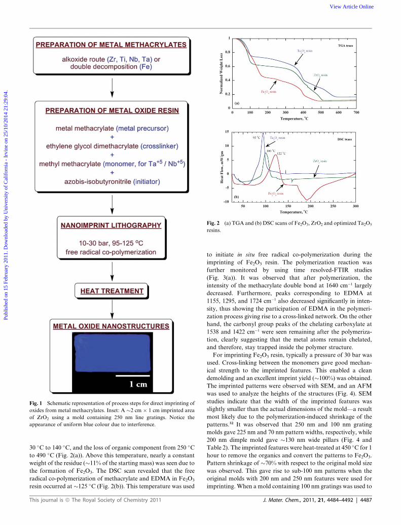
Fig. 1 Schematic representation of process steps for direct imprinting of
oxides from metal methacrylates. Inset: A �2 cm � 1 cm imprinted area
of ZrO2 using a mold containing 250 nm line gratings. Notice the
appearance of uniform blue colour due to interference.
Fig. 2 (a) TGA and (b) DSC scans of Fe2O3, ZrO2 and optimized Ta2O5
resins.
Publ
ishe
d on
15
Febr
uary
201
1. D
ownl
oade
d by
Uni
vers
ity o
f C
alif
orni
a -
Irvi
ne o
n 25
/10/
2014
21:
29:0
4.
View Article Online
30 �C to 140 �C, and the loss of organic component from 250 �C
to 490 �C (Fig. 2(a)). Above this temperature, nearly a constant
weight of the residue (�11% of the starting mass) was seen due to
the formation of Fe2O3. The DSC scan revealed that the free
radical co-polymerization of methacrylate and EDMA in Fe2O3
resin occurred at �125 �C (Fig. 2(b)). This temperature was used
This journal is ª The Royal Society of Chemistry 2011
to initiate in situ free radical co-polymerization during the
imprinting of Fe2O3 resin. The polymerization reaction was
further monitored by using time resolved-FTIR studies
(Fig. 3(a)). It was observed that after polymerization, the
intensity of the methacrylate double bond at 1640 cm�1 largely
decreased. Furthermore, peaks corresponding to EDMA at
1155, 1295, and 1724 cm�1 also decreased significantly in inten-
sity, thus showing the participation of EDMA in the polymeri-
zation process giving rise to a cross-linked network. On the other
hand, the carbonyl group peaks of the chelating carboxylate at
1538 and 1422 cm�1 were seen remaining after the polymeriza-
tion, clearly suggesting that the metal atoms remain chelated,
and therefore, stay trapped inside the polymer structure.
For imprinting Fe2O3 resin, typically a pressure of 30 bar was
used. Cross-linking between the monomers gave good mechan-
ical strength to the imprinted features. This enabled a clean
demolding and an excellent imprint yield (�100%) was obtained.
The imprinted patterns were observed with SEM, and an AFM
was used to analyze the heights of the structures (Fig. 4). SEM
studies indicate that the width of the imprinted features was
slightly smaller than the actual dimensions of the mold—a result
most likely due to the polymerization-induced shrinkage of the
patterns.32 It was observed that 250 nm and 100 nm grating
molds gave 225 nm and 70 nm pattern widths, respectively, while
200 nm dimple mold gave �130 nm wide pillars (Fig. 4 and
Table 2). The imprinted features were heat-treated at 450 �C for 1
hour to remove the organics and convert the patterns to Fe2O3.
Pattern shrinkage of �70% with respect to the original mold size
was observed. This gave rise to sub-100 nm patterns when the
original molds with 200 nm and 250 nm features were used for
imprinting. When a mold containing 100 nm gratings was used to
J. Mater. Chem., 2011, 21, 4484–4492 | 4487
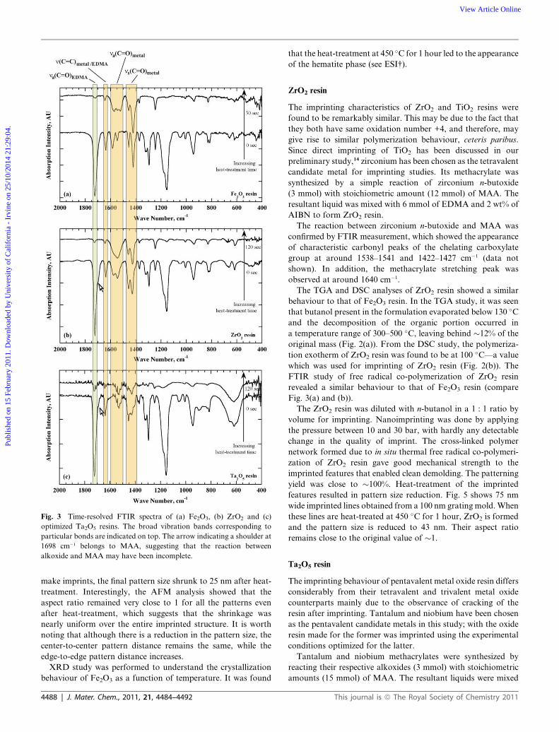
Fig. 3 Time-resolved FTIR spectra of (a) Fe2O3, (b) ZrO2 and (c)
optimized Ta2O5 resins. The broad vibration bands corresponding to
particular bonds are indicated on top. The arrow indicating a shoulder at
1698 cm�1 belongs to MAA, suggesting that the reaction between
alkoxide and MAA may have been incomplete.
Publ
ishe
d on
15
Febr
uary
201
1. D
ownl
oade
d by
Uni
vers
ity o
f C
alif
orni
a -
Irvi
ne o
n 25
/10/
2014
21:
29:0
4.
View Article Online
make imprints, the final pattern size shrunk to 25 nm after heat-
treatment. Interestingly, the AFM analysis showed that the
aspect ratio remained very close to 1 for all the patterns even
after heat-treatment, which suggests that the shrinkage was
nearly uniform over the entire imprinted structure. It is worth
noting that although there is a reduction in the pattern size, the
center-to-center pattern distance remains the same, while the
edge-to-edge pattern distance increases.
XRD study was performed to understand the crystallization
behaviour of Fe2O3 as a function of temperature. It was found
4488 | J. Mater. Chem., 2011, 21, 4484–4492
that the heat-treatment at 450 �C for 1 hour led to the appearance
of the hematite phase (see ESI†).
ZrO2 resin
The imprinting characteristics of ZrO2 and TiO2 resins were
found to be remarkably similar. This may be due to the fact that
they both have same oxidation number +4, and therefore, may
give rise to similar polymerization behaviour, ceteris paribus.
Since direct imprinting of TiO2 has been discussed in our
preliminary study,14 zirconium has been chosen as the tetravalent
candidate metal for imprinting studies. Its methacrylate was
synthesized by a simple reaction of zirconium n-butoxide
(3 mmol) with stoichiometric amount (12 mmol) of MAA. The
resultant liquid was mixed with 6 mmol of EDMA and 2 wt% of
AIBN to form ZrO2 resin.
The reaction between zirconium n-butoxide and MAA was
confirmed by FTIR measurement, which showed the appearance
of characteristic carbonyl peaks of the chelating carboxylate
group at around 1538–1541 and 1422–1427 cm�1 (data not
shown). In addition, the methacrylate stretching peak was
observed at around 1640 cm�1.
The TGA and DSC analyses of ZrO2 resin showed a similar
behaviour to that of Fe2O3 resin. In the TGA study, it was seen
that butanol present in the formulation evaporated below 130 �C
and the decomposition of the organic portion occurred in
a temperature range of 300–500 �C, leaving behind �12% of the
original mass (Fig. 2(a)). From the DSC study, the polymeriza-
tion exotherm of ZrO2 resin was found to be at 100 �C—a value
which was used for imprinting of ZrO2 resin (Fig. 2(b)). The
FTIR study of free radical co-polymerization of ZrO2 resin
revealed a similar behaviour to that of Fe2O3 resin (compare
Fig. 3(a) and (b)).
The ZrO2 resin was diluted with n-butanol in a 1 : 1 ratio by
volume for imprinting. Nanoimprinting was done by applying
the pressure between 10 and 30 bar, with hardly any detectable
change in the quality of imprint. The cross-linked polymer
network formed due to in situ thermal free radical co-polymeri-
zation of ZrO2 resin gave good mechanical strength to the
imprinted features that enabled clean demolding. The patterning
yield was close to �100%. Heat-treatment of the imprinted
features resulted in pattern size reduction. Fig. 5 shows 75 nm
wide imprinted lines obtained from a 100 nm grating mold. When
these lines are heat-treated at 450 �C for 1 hour, ZrO2 is formed
and the pattern size is reduced to 43 nm. Their aspect ratio
remains close to the original value of �1.
Ta2O5 resin
The imprinting behaviour of pentavalent metal oxide resin differs
considerably from their tetravalent and trivalent metal oxide
counterparts mainly due to the observance of cracking of the
resin after imprinting. Tantalum and niobium have been chosen
as the pentavalent candidate metals in this study; with the oxide
resin made for the former was imprinted using the experimental
conditions optimized for the latter.
Tantalum and niobium methacrylates were synthesized by
reacting their respective alkoxides (3 mmol) with stoichiometric
amounts (15 mmol) of MAA. The resultant liquids were mixed
This journal is ª The Royal Society of Chemistry 2011

Fig. 4 Composite SEM images of various as-imprinted and heat-treated structures of Fe2O3 using different molds. The insets show the structures at
higher magnification. The AFM line traces of the corresponding heat-treated imprinted structures are shown on the right.
Table 2 Summary of the approximate feature size reduction at every step of the Fe2O3 resin patterning using imprint lithography
Moldshape/size
Feature size of the imprint afterfree radical polymerization
Metal oxide feature size after the heat-treatment of imprinted structures
Total feature size reduction withrespect to mold feature size (%)
Width ofimprint/nm
Feature sizereduction (%)
Width of the metaloxide feature/nm
Feature sizereduction (%)
Dimples, 200 nm 130 35 65 50 68Lines, 250 nm 225 10 60 73 76Lines, 100 nm 70 30 25 64 75
Fig. 5 Composite SEM images of as-imprinted and heat-treated structures of ZrO2 using 100 nm line and space grating mold. Structures at higher
magnification are shown as insets. The AFM line trace of the heat-treated imprinted structures is shown on the right.
Publ
ishe
d on
15
Febr
uary
201
1. D
ownl
oade
d by
Uni
vers
ity o
f C
alif
orni
a -
Irvi
ne o
n 25
/10/
2014
21:
29:0
4.
View Article Online
with 7.5 mmol of EDMA (ideally to saturate all the methacrylate
double bonds) and 2 wt% of AIBN to give Ta2O5 and Nb2O5
resins, respectively. The formation of methacrylates was
confirmed by the FTIR spectroscopy and they were found to be
similar to that of Fe2O3, ZrO2 and TiO2 resins.
Nanoimprint lithography carried out with this formulation
of Nb2O5 resin film showed excessive cracking in the residual
layer (Fig. 6(a)). We speculate that this behaviour could be due
This journal is ª The Royal Society of Chemistry 2011
to the higher degree of cross-linking. In the cases of Fe2O3
resin, which has three methacrylate arms, and ZrO2 and
TiO2 resins, which have four methacrylate arms, the degree of
cross-linking should be lower than the pentavalent metal atom
containing Nb2O5 resin. Since the methacrylates are known to
shrink during polymerization,32 the cracking could be due to
excessive stress caused by the shrinkage along five
directions.
J. Mater. Chem., 2011, 21, 4484–4492 | 4489

Fig. 6 (a) Optimization of Nb2O5 resin by changing the amounts of EDMA and MMA with respect to Nb(OEt)5 to give a good quality imprint without
cracks. It was noticed that the ratios of Nb(OEt)5 : EDMA : MMA corresponding to 1 : 1.0 : 2 gave the best quality of imprint using a 250 nm line and
space grating mold. (b) The data from optimization of Nb2O5 resin were also used to imprint pentavalent metal containing Ta2O5 resin. The insets show
structures at higher magnification. The AFM line trace of the heat-treated imprinted structures is shown on the right.
Publ
ishe
d on
15
Febr
uary
201
1. D
ownl
oade
d by
Uni
vers
ity o
f C
alif
orni
a -
Irvi
ne o
n 25
/10/
2014
21:
29:0
4.
View Article Online
To circumvent this problem, we replaced part of cross-linker
EDMA with MMA, a monomer with one unsaturated –C]C, to
reduce the degree of cross-linking. The results of optimization
are shown as ratios between niobium ethoxide (Nb(OEt)5),
EDMA and MMA (Fig. 6(a)). When the molar amount of
EDMA is reduced by 1 and instead replaced by the same amount
of MMA, the cracking in the residual layer showed noticeable
reduction. However, further replacement of EDMA with MMA
(Nb(OEt)5 : EDMA : MMA ¼ 1 : 0.5 : 2) resulted in excessive
cracking. This may be due to higher degree of cross-linking
within methacrylate arms of niobium methacrylate in the absence
of sufficient monomeric cross-linkers to cushion the stress arising
due to shrinkage. Now when the amount of MMA is increased to
give a composition ratio Nb(OEt)5 : EDMA : MMA ¼1 : 0.5 : 3, the quality of the imprint increased dramatically with
cracks visible only close to the imprinted lines. The best
composition was found to be Nb(OEt)5 : EDMA : MMA ¼1 : 1.0 : 2, which was devoid of cracks after imprinting.
Similar trend was also seen in the imprinting characteristics
of Ta2O5 resin as tantalum is a pentavalent atom (see ESI†).
Unsurprisingly, Ta2O5 resin gave best imprints for the same
4490 | J. Mater. Chem., 2011, 21, 4484–4492
composition as used for Nb2O5 resin (Fig. 6(b)). SEM images
of the heat-treated samples also showed shrinkage of the
imprinted material, but to a lesser degree than what has been
seen for Fe2O3 and ZrO2 resins. For example, Ta2O5 resin
imprinted by 250 nm line and space mold gave 210 nm line-
widths, which on heat-treatment at 550 �C for 1 hour gave
�100 nm lines. AFM measurements revealed that the aspect
ratio of these lines was close to 1.5, unlike �1 obtained for
Fe2O3 and ZrO2 lines.
The TGA of optimized composition of Ta2O5 resin showed
similar behaviour to that of the other metal methacrylates
described earlier. The organics were completely degraded at
about 580–590 �C, leaving behind the metal oxide residue.
Compared to the other metal oxide resins, the pentavalent resins
required higher temperature to completely decompose the
organics, which may be due to the higher degree of cross-linking
between five-armed methacrylate and EDMA (Fig. 2(a)). DSC
analysis of this composition showed that the polymerization
took place at about 95 �C (Fig. 2(b)). The polymerization
behaviour, studied using the FTIR, was consistent with previ-
ously described metal oxide resins (Fig. 3(c)).
This journal is ª The Royal Society of Chemistry 2011

Publ
ishe
d on
15
Febr
uary
201
1. D
ownl
oade
d by
Uni
vers
ity o
f C
alif
orni
a -
Irvi
ne o
n 25
/10/
2014
21:
29:0
4.
View Article Online
4. General remarks
Direct imprinting of metal oxides by in situ thermal free radical
co-polymerization of their respective metal methacrylates with
EDMA has remarkable similarities. They all use liquid mono-
mers which undergo co-polymerization during imprinting.
Polymerization rigidly shapes the imprinted patterns, traps the
metal atoms, reduces the surface energy and strengthens the
structures, thereby giving �100% yield after demolding. Ther-
molysis of the imprinted patterns converts them to their corre-
sponding oxides with much smaller feature size than what was on
the original mold. There are, however, some significant differ-
ences as well. It was observed that the quality of an imprint and
its subsequent conversion to oxide varies with spin-coating
speed. In the case of Fe2O3 resin, after coating at 3000 rpm, an
imprint with a residual layer as thick as �600 nm showed no
cracking even after heat-treatment (see ESI†). Similar observa-
tion was also made for TiO2 resin which had a residual layer
thickness of �1200 nm. However, in the case of ZrO2 resin,
although the imprint with residual layer thickness of �1800 nm
did not show any cracking, fine cracks were seen after heat-
treatment, most likely arising due to thermal stresses. When ZrO2
resin was spin-coated at 6000 rpm and imprinted (residual layer
thickness �900 nm), the problem of cracking was somewhat
alleviated after heat-treatment (see ESI†). Not surprisingly,
crack-free imprints after heat-treatment were seen when ZrO2
resin was diluted with n-butanol in a 1 : 1 ratio to give even
thinner residual layer, slightly less than half the thickness of what
was obtained at 6000 rpm without dilution (Fig. 5). Likewise, in
the case of Ta2O5 and Nb2O5 resins, the optimized composition
gave good imprint at 3000 rpm, and the quality was improved
further at 6000 rpm.
Metal methacrylates used in this work are multi-functional
and can act as cross-linkers. So, why use another cross-linker like
EDMA as well? It was observed that metal methacrylates have
poor film forming ability, and when imprinted, they showed a lot
of cracking as well as poor adhesion to the silicon substrate.
However, with the addition of EDMA, not only better film
adhesion to substrate was observed but also the quality of
imprint improved substantially. Furthermore, EDMA is miscible
in metal methacrylates prepared in this study and this helped in
optimization of metal oxide resins. The content of EDMA in the
resin affects the imprint quality. In most cases, the best
imprinting results were achieved when the content of EDMA was
just enough to ideally saturate all the –C]C bonds in metal
methacrylate during polymerization.
Direct imprinting of metal oxides by the metal methacrylate
route offers significant advantages over the sol–gel-based route
which mainly uses a soft mold for nanoimprint lithography.
Unlike the critical requirement of solvent in the sol–gel material
for imprinting, metal methacrylates can be dissolved in liquid
monomers which can then be imprinted at lower pressures
without worrying about the removal of solvent. In fact, presence
of small amount of solvent left over in the spin-coated film aids in
imprinting at lower pressures and its presence does not seem to
hinder polymerization. The polymerization in this system is
comparable to bulk polymerization (without solvent), which
gives rise to hardened pattern features and thus facilitates clean
demolding with�100% yield over large areas. This approach has
This journal is ª The Royal Society of Chemistry 2011
the capability of producing high-throughput at a very high
resolution, which is not possible when a soft mold is used. Using
our approach, one could make sub-100 nm imprints over >2 cm
� 1 cm by using molds containing sub-micron pattern features,
which can translate into huge cost savings (Fig. 1, inset).
Furthermore, by adjusting the metal content in the overall
formulation, one should be able to control the degree of pattern
shrinkage after heat-treatment.
Unlike the conventional nanoimprint lithography using an
organic resist, where the residual layer can be easily removed by
reactive ion etching, it is difficult to remove the residual layer by
such techniques when the resin is composed of organometallics.
However, a physical bombardment method was demonstrated to
be useful to remove poly(ferrocenylmethylphenylsilane) residual
layer.33 Using this method, it may be possible to obtain isolated
patterns of metal oxides. Furthermore, our method also has the
potential to fabricate metal lines by hydrogen reduction of metal
oxides which reside above the water formation line (i.e., H2 +
½O2 ¼ H2O line) in the Ellingham diagram. In other words,
imprinted patterns containing metal oxides such as NiO, CuO,
PbO, CoO, etc., which are thermodynamically less stable than
water, can be reduced by hydrogen to their respective metals.34
5. Conclusions
Using in situ thermal co-polymerization of the metal methacry-
lates with cross-linker EDMA during imprinting and their
subsequent thermolysis, we have demonstrated a facile and
general route to direct imprint lithography of various metal
oxides. This approach enabled us to fabricate large area nano-
scale patterns of various metal oxides such as Fe2O3, TiO2, ZrO2,
Nb2O5, and Ta2O5. Resin formulations were made by mixing
individual metal methacrylates with EDMA and AIBN. All the
metal oxide resins underwent thermally initiated free radical co-
polymerization, leading to lowering of surface energy and
strengthening of the imprint, which enabled easy and clean
demolding. Since the metal atoms remain trapped inside the
polymer matrix, subsequent thermolysis in air yielded the cor-
responding metal oxide patterns. Shrinkage of pattern size was
observed in all the metal oxide resin imprints due to the loss of
organics giving rise to oxide feature sizes as small as 25 nm. While
the imprint characteristics of Fe2O3, TiO2 and ZrO2 resins were
similar, optimization of the resin composition was necessary in
the case of Nb2O5 and Ta2O5 resins to reduce the cross-linking
density in order to obtain crack-free residual layer. This was
achieved by suitably adjusting the amounts of EDMA and
MMA. By tweaking the chemistry of metal oxide resins, our
technique can potentially be extended to UV nanoimprinting of
oxides as well as to pattern multi-component oxide systems.
Acknowledgements
The authors would like to thank Lim Poh Chong of Institute of
Materials Research and Engineering for his assistance in XRD.
This work was supported by the IMRE-funded core project no.
IMRE/09-1C0319.
J. Mater. Chem., 2011, 21, 4484–4492 | 4491

Publ
ishe
d on
15
Febr
uary
201
1. D
ownl
oade
d by
Uni
vers
ity o
f C
alif
orni
a -
Irvi
ne o
n 25
/10/
2014
21:
29:0
4.
View Article Online
References
1 For recent comprehensive reviews on nanoimprint lithography see:H. Schrift, J. Vac. Sci. Technol., B, 2008, 26, 458; E. A. Costner,M. W. Lin, W.-L. Jen and C. G. Willson, Annu. Rev. Mater. Res.,2009, 39, 155. They should be read in conjunction with anotherreview by L. J. Guo, Adv. Mater., 2007, 19, 495. For a recentreview and examples of micromolding/wet lithography techniquessee: M. Cavallini, C. Albonetti and F. Biscarini, Adv. Mater., 2009,21, 1043; M. Cavallini, M. Murgia and F. Biscarini, Nano Lett.,2001, 1, 193.
2 M. Li, H. Tan, L. Chen, J. Wan and S. Y. Chou, J. Vac. Sci. Technol.,B, 2003, 21, 660.
3 S. Matsui, Y. Igaku, H. Ishigaki, J. Fujita, M. Ishida, Y. Ochiai,H. Namatsu and M. Komuro, J. Vac. Sci. Technol., B, 2003, 21, 688.
4 W. S. Kim, K. B. Yoon and B. S. Bae, J. Mater. Chem., 2005, 15,4535.
5 O. F. G€obel, M. Nedelcu and U. Steiner, Adv. Funct. Mater., 2007, 17,1131.
6 S. J. Kwon, J. H. Park and J. G. Park, J. Electroceram., 2006, 17, 455.7 M. J. Hampton, S. S. Williams, Z. Zhou, J. Nunes, D. H. Ko,
J. L. Templeton, E. T. Samulski and J. M. DeSimone, Adv. Mater.,2008, 20, 2667.
8 K.-Y. Yang, K.-M. Yoon, K. W. Choi and H. Lee, Microelectron.Eng., 2009, 86, 2228.
9 K.-Y. Yang, K.-M. Yoon, S. Lim and H. Lee, J. Vac. Sci. Technol., B,2009, 27, 2786.
10 K.-M. Yoon, K.-Y. Yang, H. Lee and H.-S. Kim, J. Vac. Sci.Technol., B, 2009, 27, 2810.
11 Y. Kang, M. Okada, K.-I. Nakamatsu, K. Kanda, Y. Haruyama andS. Matsui, J. Vac. Sci. Technol., B, 2009, 27, 2805.
12 H. Han, A. Bhushan, F. Yaghmaie and C. E. Davis, J. Vac. Sci.Technol., B, 2010, 28, 78.
13 H.-H. Park, D.-G. Choi, X. Zhang, S. Jeon, S.-J. Park, S.-W. Lee,S. Kim, K.-D. Kim, J.-H. Choi, J. Lee, D. K. Yun, K. J. Lee, H.-H. Park, R. H. Hill and J.-H. Jeong, J. Mater. Chem., 2010, 20, 1921.
14 S. H. Lim, M. S. M. Saifullah, H. Hussain, W. W. Loh andH. Y. Low, Nanotechnology, 2010, 21, 285303.
4492 | J. Mater. Chem., 2011, 21, 4484–4492
15 N. Tohge, K. Shinmou and T. Minami, Proc. SPIE Sol-Gel Optics III,1994, vol. 2288, p. 589.
16 N. Tohge, K. Shinmou and T. Minami, J. Sol-Gel Sci. Technol., 1994,2, 581.
17 K. Shinmou, N. Tohge and T. Minami, Jpn. J. Appl. Phys., 1994, 33,L1181.
18 G. Zhao and N. Tohge, J. Ceram. Soc. Jpn., 1995, 103, 1293.19 G. Zhao and N. Tohge, Kobunshi Ronbunshu, 1996, 53, 253.20 G. Zhao, N. Tohge and J. Nishii, Jpn. J. Appl. Phys., 1998, 37,
1842.21 M. S. M. Saifullah, M. Z. R. Khan, D. Hasko, E. S. P. Leong,
X. L. Neo, E. T. L. Goh, D. Anderson, G. A. C. Jones andM. E. Welland, J. Vac. Sci. Technol., B, 2010, 28, 90.
22 M. S. M. Saifullah, D. J. Kang, K. R. V. Subramanian,M. E. Welland, K. Yamazaki and K. Kurihara, J. Sol-Gel Sci.Technol., 2004, 29, 5.
23 K. R. V. Subramanian, M. S. M. Saifullah, E. Tapley, D. J. Kang,M. E. Welland and M. Butler, Nanotechnology, 2004, 15, 158.
24 M. S. M. Saifullah, K. R. V. Subramanian, E. Tapley, D. J. Kang,M. E. Welland and M. Butler, Nano Lett., 2003, 3, 1587.
25 K. R. V. Subramanian, PhD thesis, University of Cambridge, 2006.26 B. Y. Liu and S. T. Ho, J. Electrochem. Soc., 2008, 155, P57.27 B. Y. Liu, Y. Y. Huang, G. Y. Xu and S. T. Ho, Nanotechnology,
2008, 19, 155303.28 N. E. Voicu, M. S. M. Saifullah, K. R. V. Subramanian,
M. E. Welland and U. Steiner, Soft Matter, 2007, 3, 554.29 W.-C. Liao and S. L.-C. Hsu, Nanotechnology, 2007, 18, 065303.30 M. Zelsmann, K. Perez Toralla, J. De Girolamo, D. Boutry and
C. Gourgon, J. Vac. Sci. Technol., B, 2008, 26, 2430.31 Y. Gotoh, J. Imakita, Y. Ohkoshi and M. Nagura, Polym. J., 2000,
32, 838.32 M. P. Patel, M. Braden and K. W. Davy, Biomaterials, 1987, 8,
53.33 C. Acikgoz, M. A. Hempenius, G. J. Vancso and J. Huskens,
Nanotechnology, 2009, 20, 135304.34 M. Nedelcu, M. S. M. Saifullah, D. G. Hasko, A. Jang, D. Anderson,
W. T. S. Huck, G. A. C. Jones, M. E. Welland, D. J. Kang andU. Steiner, Adv. Funct. Mater., 2010, 20, 2317.
This journal is ª The Royal Society of Chemistry 2011